chapter comm 43 anhydrous ammonia - wisconsin · chapter comm 43 anhydrous ammonia ... 45 are not...
TRANSCRIPT
DEPARTMENT OF COMMERCE Comm 43.02
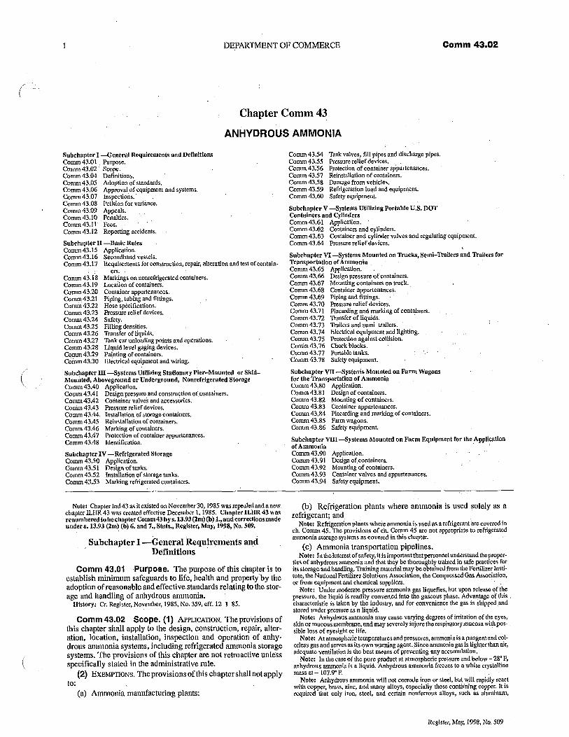
Chapter Comm 43
ANHYDROUS AMMONIA
Subchapter I -General Requirements and DefinitionsComm 43.01 Purpose,Comm 43.02 Scope.Comm 43.04 Definitions.Comm 43.05 Adoption of standards.Comm 43.06 Approval of equipment and systems.Comm 43.07 Inspections.Comm 43.08 Petition for variance.Comm 43.09 Appeals.Comm 43.10 _Penalties,Comm43.11 Fees.Comm 43.12 Reporting accidents.
Subchapter H -Basle RulesComm 43.15 Application.Comm 43.16 Secondhand vessels.Comm 43.17 Requirements for construction, repair, alteration and test of contain-
ers.Comm 43.18 Markings on nonrefrigeratedcontainers.Comm 43.19 location of containers.Comm 43.20 Container appurtenances.Comm 43.21 Piping, tubing and fittings.Comm 43.22 Hose specifications,Comm 43.23 Pressure relief devices.Comm43.24 Safety.Comm 43.25 Filling densities.Comm 43.26 Transfer of liquids.Comm 43.27 Tank car unloading points and operations.Comm 43.28 liquid level gaging devices.Comm 43.29 Painting of containers.Comm 43.30 Electrical equipment and wiring.
Suhchapter III -SystemsiltillzingStationaryPier-dltounted orSk[d-Mounted, Aboveground or Underground, Nourefrlgerated StorageComm 43.40 Application.Copim 43A I Design pressure and construction of wntainefs.Comm43A2 Container valves and accessories.Comm 43.43 Pressure relief devices.Comm 43.44 Installation of storage containers,Comm 43.45 Reinstallation of containers.Comm 43.46 Marking of containers.Comm 43.47 Protection of container appurtenances.Comm 43A8 Identification.
Subchapter IV -Refrigerated StorageComm 43.50 Application.Comm 43.51 Design of tanks.Comma 43.52 Installation of storage tanks.Conan 43.53 Marking refrigerated containers.
Note. Chapterind 43 as it existed on November30, 1985 was repealed and anewchapter ILHR 43 was created effective December 1, 1985. Chapter IL1IR 43 Hasrenumbered lobe chapter Comm 43 by s. 13,93 (2m) (b) I., and corrections madeunder s. 13.93 (2m) (b) 6. and 7., Stats., Register, May, 1998, No. 509.
Subehapter I -General Requirements andDefinitions
Comm 43.01 Purpose. The purpose of this chapter is toestablish minimum safeguards to life, health and property by theadoption of reasonable and effective standards relating to the stor-age and handling of anhydrous ammonia.
History: Cr. Register, November, 1985, No. 359, elf. 12-1-85.
Comm 43.02 Scope. (1) APPUCAT10N, The provisions ofthis chapter shall apply to the design, construction, repair, alter-ation, location, installation, inspection and operation of anhy-drous ammonia systems, including refrigerated ammonia storagesystems. The provisions of this chapter are not retroactive unlessspecifically stated in the administrative rule.
(2) ExnMPTfoNs. The provisions of this chapter shall not applyto:
(a) Ammonia manufacturing plants:
Comm 43.54 Tank valves, fill pipes and discharge pipes.Comm 43.55 Pressure relief devices. .Comm 43.56 Protection of container appurtenances.Comm 43.57 Reinstallation of containers.Comm 43.58 Damage from vehicles.Comm 43.59 Refrigeration load and equipment.Comm 43.60 Safety equipment.
Subchapter V -Systems Utilizing Portable U.S. DOTConlainers and CylindersComm43.61 Application.Comm 43.62 Containers and cylinders.Comm 43.63 Container and cylinder valves and regulating equipment.Comm 43.64 Pressure relief devices.
Subchapter VI--Systems Mounted on Trucks, Senti-Tbailers and Trailers forTransportation of AmmoniaComm 43.65 Application.Comm 43.66 Design pressure of containers.Comm 43.67 Mounting containers on truck.Comm 43.68 Container appurtenances.Comm 43.69 Piping and fittings.Comm 43.70 Pressure relief devices.Comm 43.71 Placarding and marking of containers.Comm 43.72 Transfer of liquids.Comm 43.73 'hailers and semi-Arailers.Comm 43.74 Electrical equipment and lighting.Comm 43.75 Protection against collision.Comm 43.76 Chock blocks.Comm 43.77 Portable tanks.Comm 43.78 Safety equipment.
Subchapter VII --Systems Mounted on Farm Wagonsfor the Transportation of AmmoniaComm 43.80 Application.Comm 43.81 Design of containers.Comm 43.82 Mounting of containers.Comm 43.83 Container appurtenances.Comet 43.84 Placarding and marking of containers.Comm 43-85 Farm wagons.Comm 43.86 Safety equipment,
Subchapter VIII --Systems Mounted on Farm Equipment for the Applicationof AmmoniaComm 43.90 Applicadon.Comm 43.91 Design of.comainers,Comm 43.92 Mounting of containers.Comm 43.93 Container valves and appurtenances.Comm 43.94 Safety equipment.
(b) Refrigeration plants where ammonia is used solely as arefrigerant; and
Note: Refrigeration plants where ammonia is used as a refrigerant arecovered inch. Comm 45. The provisions of ch. Comm 45 are not appropriate to refrigeratedammonia storage systems as covered in this chapter,
(c) Ammonia transportation pipelines.Note: In theinterest of safety, it is important that personnel understand the proper-
des of anhydrous ammonia and that they be thoroughly trained in safe practices forits storage and bandling. Training material maybe obtained from the Ferlilizer Insti-tute, the National Fertilizer Solutions Association, the Compressed Gas Association,or from equipment and chemical suppliers.
Note; Under moderate pressure ammonia gas liquefies, but upon release of thepressure, the liquid is readily converted into the gaseous phase. Advantage of thischaracteristic is taken by the industry, and for convenience the gas is shipped,andstored under pressure as a liquid.
Note: Anhydrous ammonia may cause varying degrees of irritation of the eyes,Skin or mucous membrane, and may severely injure therespiratorymucosa with pos-sible loss of eyesight or life.
Note: At atmospheric terriperaluresand pressures, ammonia is a pungent and col-orless gas and serves as its own warning agent. Since ammonia gas is lighter than air,adequate ventilation is the best means of preventing any accumulation,
Note: In the case of the pure product at atmospheric pressure and below - 28° P,anhydrous ammonia is a liquid. Anhydrous ammonia freezes to a white crystallinemass at -107.9° F.
Note: Anhydrous ammonia will not corrode iron or steel, but will rapidly reactwith copper, brass, zinc, and many alloys, especially those containing copper. It isrequired that only iron, steel, and certain nonferrous alloys, such as aluminum,
Register, May, 1998, No. 509
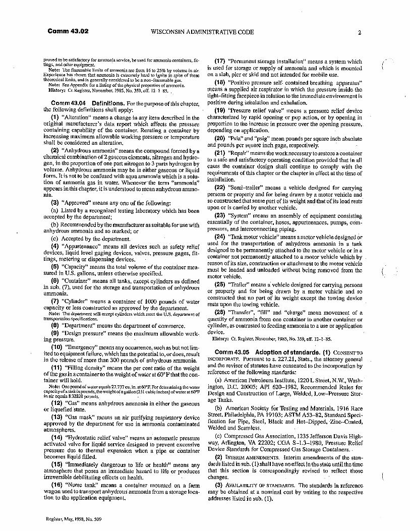
Comm 43.02 WISCONSIN ADMINISTRATIVE CODE 2
proved to be satisfactory for ammonia service, be used for anucwnia containers, fit-tings, and other equipment.
Note: The flanunable limits of amn onia are from 16 to 25% by volume in air.Experience has shown that ammonia is extremely hard to ignite in spite of thesetheoretical limits, and is generally considered to he a non-flammable gas.
Note; Sec Appendix for a listing of the physical properties of ammonia.History. Cr. Register, November, 1985, No, 359, off. 12-1-85,
Comm43.04 Definitions. Forthe purpose of this chapter,the following definitions shall apply:
(1) "Alteration" nicans a change in any item described in theorigiftal manufacturer's data report which affects the pressurecontaining capability of the container. Rerating a container byincreasing maximum allowable working pressure or temperatureshall be considered an alteration.
(2) "Anhydrous ammonia" means the compound formed by achemical combination of 2 gaseous elements, nitrogen and hydro-gen, in the proportion of one part nitrogen to 3 parts hydrogen byvolume, Anhydrous ammonia may be in either gaseous or liquidform. It is not to be confused with aqua ammonia which is a solu-tion of ammonia gas in water. Whenever the term "ammonia"appears in this chapter, it is understood to mean anhydrous ammo-nia.
(3) "Approved" means any one of the following:(a) Listed by a recognized testing laboratory which has been
accepted by the department;(b) Recommended by the manufacturer as suitable for use with
anhydrous ammonia and so marked; or(c) Accepted by the department.(4) "Appurtenance" means all devices such as safety relief
devices, Iiquid level gaging devices, valves, pressure gages, fit-tings, metering or dispensing devices.
(5) "Capacity" means the total volume of the container mea-sured in U.S. gallons, unless otherwise specified.
(6) "Container" means all tanks, except cylinders as definedin sub. (7), used for the storage and transportation of anhydrousammonia.
(7) "Cylinder" means a container of 1000 pounds of watercapacity or less constructed as approved by the department.
Note: The department will accept cylinders which meet the U.S. department oftransportation specifications.
(8) "Department" means the department of commerce.(9) "Design pressure" means the maximum allowable work-.
ing pressure.(10) "Emergency" means any occurrence, such as but not lim-
ited to equipment failure, which has the potential to, or does, resultin the release of more than 300 pounds of anhydrous ammonia.
(11) "Filling density" means the per cent ratio of the weightof the gas in a container to the weight of water at 60'F that the con-tainer will hold,
Note: One pound of water equals 27.737 cu. in. at WE For determining the watercapacity of a tank in pounds, the weight of a gallon (231 cubic inches) of water at 60"Fin air equals 8.32828 pounds.
(12) "Gas" means anhydrous ammonia in either the gaseousor liquefied state.
(13) "Gas mask" means an air purifying respiratory deviceapproved by the department for use in ammonia contaminatedatmospheres.
(14) "Hydrostatic relief valve" means an automatic pressureactivated valve for liquid service designed to prevent excessivepressure due to thermal expansion when a pipe or containerbecomes liquid filled.
(15) "Immediately dangerous to life or health" means anyatmosphere that poses an immediate hazard to fife or producesirreversible debilitating effects on health.
(16) "Nurse tank" means a container mounted on a farmwagon used to transport anhydrous ammonia from a storage loca-tion to the application equipment.
(17) "Permanent storage installation" means a system whichis used for storage or supply of ammonia and which is mountedon a slab, pier or skid and not intended for mobile use.
(18) "Positive pressure self--contained breathing apparatus"means a supplied air respirator in which the pressure inside thetight—fitting facepiece in relation to the immediate environment ispositive during inhalation and exhalation.
(19) "Pressure relief valve" means a pressure relief devicecharacterized by rapid opening or pop action, or by opening inproportion to the increase in pressure over the opening pressure,depending on application,
(20) "Psia" and "psig" mean pounds per square inch absoluteand pounds per square inch gage, respectively.
(21) "Repair" means the work necessary to restore a containerto a safe and satisfactory operating condition provided that in allcases the container design shall continue to comply with therequirements of this chapter or the chapter in effect at the time ofinstallation.
(22) "Semi—trailer" means a vehicle designed for carryingpersons or property and for being drawn by a motor vehicle andso constructed that some patt of its weight and that of its load restsupon or is carried by another vehicle.
(23) "System" means an assembly of equipment consistingessentially of the container, hoses, appurtenances, pumps, com-pressors, and interconnecting piping.
(24) "Tank motor vehicle" means a motor vehicle designed orused for the transportation of anhydrous ammonia in a tankdesigned to be permanently attached to the motor vehicle or in acontainer not permanently attached to a motor vehicle which by .reason of its size, construction or attachment to the motor vehiclemust be loaded and unloaded without being removed from themotor vehicle.
(25) "Trailer" means a vehicle designed for carrying personsor property and for being drawn by a motor vehicle and soconstructed that no part of its weight except the towing devicerests upon the towing vehicle.
(26) "Transfer", "fill" and "charge" mean movement of aquantity of atnmonia from one container to another container orcylinder, as contrasted to feeding ammonia to a use or applicationdevice.
History. Cr. Register, November, 1985, No. 359, eff. 12-1-85.
Comm 43,05 Adoption of standards. (1) CONS13NTTO
INCORPORATE. PUrSUant to s. 227.21, Stats., the attorney generaland the revisor of statutes have consented to the incorporation byreference of the following standards:
(a) American Petroleum Institute, 1220 L Street, N.W., Wash-ington, D.C. 20005; API 620-1982, Recommended Rules forDesign and Construction of Large, Welded, Low—Pressure Stor-age Tanks.
(b) American Society for Testing and Materials, 1916 RaceStreet, Philadelphia, PA 19103; ASTM A53-82, Standard Speci-fication for Pipe, Steel, Black and Hot—Dipped, Zinc—Coated,Welded and Seamless.
(c) Compressed Gas Association, 1235 Jefferson Davis High-way, Arlington, VA 22202; CGA S-13-1980, Pressure ReliefDevice Standards for Compressed Gas Storage Containers.
(2) INTERIAI A-MENDMENTS. Interim amendments of the stan-dards listed in sub. (1) shall have no effect in the state until the timethat this section is correspondingly revised to reflect thosechanges.
(3) AvA1LABILITY OF STANDARDS. The standards in referencemay be obtained at a nominal cost by writing to the respectiveaddresses listed in sub. (1).
Register, May, 1998, No. 509
DEPARTMENT OF COMMERCE
Comm 43.12
(4) FILING of STANDARDS. Copies of the standards in referenceare on file in the offices of the department, the secretary of stateand the revisor of statutes.
History: Cr. Register, November, 1985, No. 359, eff. 12-1-85; correction in (1)(intro.) made under s. 13.93 (2m) (b) 7., Slats., Register, June, 1995, No. 474.
Comm 43.06 Approval of equipment and systems.(1) DEPARTMENT APPRovAL. Before construction of any new oradditional permanent storage installation for the storage or han-dling of anhydrous ammonia is undertaken, approval of thedepartment shall be obtained. The department shall review andmake a determination on an application for installation approvalwithin 15 business days of receiving complete information as spe-cified in sub. (2).
(2) REQUIRED INFORMATION. In applying for departmentapproval, the following information shall be submitted in writingtogether with at least 2 prints of scaled engineering plans of theproposed construction or installation:
(a) The name of the person, firm or corporation proposing theconstruction or installation;
(b) The location of the proposed construction or installationshowing the property lines on all sides and adjacent railways,streets and highways;
(c) A plot of the area to be utilized showing location of build-ings, tanks, loading and unloading points and clearances as cov-ered in s. Comm 43.19;
(d) A plot plan showing the land use of the area surroundingthe proposed site for a distance of 2000 feet;
(e) The capacity and outside surface area of each tank; and(f) The size, manufacturer, catalog number and capacity of
safety relief valves.(3) LOCAL APPROVAL. Approval of a permanent storage instal-
lation site shall be obtained from the local fire department andshall be verified at the time of plan submittal.
History: Cr. Register, November, 1985, No. 359, eff. 12-1-S5.
Comm 43.07 Inspections. (1) GENERALREQUIREMENTS.The authorized inspectors of the department, upon presentingappropriate credentials to the owner, operator or agent in charge,may:
(a) Enter without delay and at reasonable times any factory,plant, establishment, construction site or other area, workplace orenvironment where work is performed by an employe of anemployer; and
(b) Inspect and investigate during regular working hours andat other reasonable times, and within reasonable limits and in areasonable manner, any place of employment and all pertinentconditions, structures, machines, apparatus, devices, equipmentand materials therein, and to question privately any employer,owner, operator, agent or employe.
(2) REPRESENTATION. The inspector, before making an inspec-tion, shall contact the employer or employer's representative.whoshall be given an opportunity to accompany the inspector duringthe physical inspection of any workplace under sub. (1).
Note: The department procedure is not to give advance notice. In the schedulingand in the act of inspecting it may not always be possible to avoid advance notice orto obtain accompaniment, but otherwise these rules will be diligently observed.
(3) INITIAL INSPECTIONS. Anhydrous ammonia systems whichrequire approval under s. Comm 43.06 shall be inspected by thedepartment before the systems are placed in operation. Thedepartment shall conduct the inspection within 15 business daysof receiving the request for inspection.
(4) PERIODIC INSPECTIONS. Permanent storage tanks exceed-ing 2000 gallons water capacity and all anhydrous ammonia nursetanks located at storage facilities shall be subject to an inspectionby the department at least once every 3 years.
_History: Cr. Register, November, 1985, No. 359, eff, 12-145.
Comm 43.08 .Petition for variance. (1) PROCEDURE.The department shall consider and may grant a variance to anadministrative rule upon receipt of a fee, a completed petition forvariance form from the owner and, where applicable, a completedposition statement from the chief of the local fire department, pro-vided an equivalency is established in the petition for variancewhich meets the intent of the rule being petitioned. The depart-ment may impose specific conditions in granting a variance topromote the protection of the health, safety or welfare of theemployes or the public, Violation of those conditions under whichthe variance is granted shall constitute a violation of the rules ofthis chapter.
Note: Copies of the petition for variance application form (SBD,-9890) are avail-able at no charge from thaDivisionof Safety and Buildings, P.O. Box 7152, Madison,Wisconsin 53707.
Note: Section 101.02(6),Stats,andch.ILHR3 outline the procedure for submit-ting petitions to the department and the department procedures forbearing petitions.
(2) PETITION PROCESSING TIME. Except for priority petitions,the department shall review and make a determination on a peti-tion for variance within 30 business days of receipt of ail calcula-tions, documents and fees required to complete the review, Thedepartment shall process priority petitions within 10 businessdays of receipt of the required items.
Il story: Cr. Register, November, 1985, No. 359, eff. 12-145.
Comm 43.09 Appeals. (1) APPEAL OF LOCAL ORDER.Any person affected by a local order which may be in conflict witha rule of the department may petition the department for a hearingon the grounds that the local order is unreasonable and in conflictwith the rule of the department.
Note: Section 101.01 (8), Slats., defines "local order" as any ordinance, order, ruleor determination of any common council, board of alderpersons, board of trustees orthe village board, or any village or city, or the board of health of any municipality,or an order or d irection of any official of such municipality, upon any matter overwhich the department has jurisdiction.
(2) PETITION OF ADMINISTRAnVE RULE. Pursuant to s. 227.12,Stats., any municipality, corporation or any 5 or more persons hav-ing an interest in an administrative rule may petition the depart-ment requesting the adoption, amendment or repeal of the rule.
History: Cr. Register, November, 1985, No. 359, eff. 12-1-85; correction madeunder . s. 13.93 (2m) (b) 7., Stats., Register, June, 1995, No. 474.
Comm 43.10 Penalties. Penalties for violation of anyrule in this chapter shall be assessed in accordance with s. 10 1,02,Stats,
Note: Section 101.02 (13) (a), Slats., indicates penalties will be assessed againstany employer, employe, owner or other person who fails or refuses to perform anyduty lawfully enjoined, within the time prescribed by the department, for which nopenalty has been specifically provided, or who fails, neglects or refuses to complywith any lawful order made by the department, or any judgment or decree made byany court in connectionwith ss.101.01 to 101.25, Stats.Foreaeb such violation, "l-ure or refusal, such employe, owneror other person must forfeit and pay into the statetreasury a sum not less than $10 nor more than $100 for each violation.
Note: Section 101.02 (12), Slats., indicates that every day during which any per-son, parsons, corporation or, any officer, agent or employe thereof, fails to obsme andcomply with an order of the department will constitute a separate and distinct viola-tion of such order.
History; a. Register, November, 1985, No. 359, eff, 12-1--85,
Comm 43.11 Fees. Fees for the plan examination, regis-tration and inspection of anhydrous ammonia systems shall besubmitted as specified in ch. Comm 2.
History: Cr. Register, Novembe,1985, No. 359, eff. 12-1-85; correction mad-,under s. 13.93 (2m) (b) 7., Slats., Register, June, 1995, No. 474.
Comm 43.12 Reporting accidents. Whenever an acci-dent occurs at an anhydrous ammonia installation and causes per-sonal injury requiring professional medical attention, the owneror operator shall report the facts involved to the department within2 business days.
History: Cr. Register, November, 1985, No. 359, eff. 12-1-85.
Register, May, 1998, No. 509
Comm 43.12
WISCONSIN ADMINISTRATIVE CODE
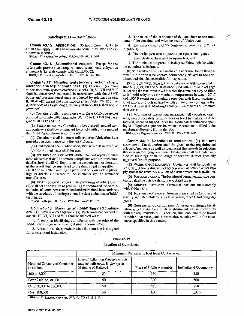
Subchapter 11 —Basic Rules 3. The name of the fabricator of the container or the tradename of the container and with the year of fabrication;
Comm 43:15 Application. Sections Comm 43.15 to 4. The water capacity of the container in pounds at 60° F or43.30 shall apply to all anhydrous ammonia installations unless in gallons;otherwise specified.
History: Cr. Register, November, 1985, No. 359, eff.5. The design pressure in pounds per square inch gage;6. The outside surface area in square feet; and
Comm 43.16 Secondhand vessels, Except for thehydrostatic pressure test requirements, secondhand anhydrousammonia tanks shall comply with ch. ILHR 42.
History: Cr. Register, November, 1985, N11). 359, eff. 12-1-85.
Comm43.17 Requlrements for construction, repair,alteration and test of containers. (1) GENERAL. (a) Con-tainers used with systems covered in subchs.111, VI, VII and VIIIshall be constructed and tested in accordance with the ASMEboiler and pressure vessel code as adopted by reference in chs.ILHR 41-42, except that construction under Table UW 12 of theASME code at a basic joint efficiency of under 80% shall not bepermitted.
(b) Containers built in accordance with the ASME code are notrequired to comply with paragraphs UG 125 to UG 128 and para-graphs UG 132 and 133.
(2) STRESS RELIEVING. Containers other than refrigerated stor-age containers shall be constructed to comply with one or more ofthe following additional requirements:
(a) Containers shall be stress relieved after fabrication by aprocedure in accordance with the ASME code;
(b) Cold formed heads, when used, shall be stress relieved; or(c) Hot formed heads shall be used.(3) WELDED REPAIR OR ALTERATION. Welded repair or alter-
ation of the vessel shall be done in compliance with the proceduresdetailed in ch. ILHR 42, Reports for the welded repair or alterationof the vessel shall be submitted to the department as specified inch. ILHR 42. Other welding is permitted only on saddle plates,lugs or ,brackets attached to the container by the containermanufacturer.
(4) EXISTING 1NSTALLAT1oNS. The provisions of subs. (1) and(2) shall not be construed as prohibiting the continued use or rein-stallation of containers constructed and maintained in accordancewith the standards of the department in effect at the time of initialinstallation.
History: Cr. Register, November, 1985, No. 359, eff. 12-1 85.
Comm 43.18 Markings on nonrefrlgerated contain-ers. (1) 1NFoRAiATEON REQUIRED. (a) Each container covered insubchs. III, VI, VII and VIII shall be marked with:
1. A marking identifying compliance with the rules of theASME code under which the container is constructed;
2. A notation on the container when the container is designedfor underground installation;
7. The minimum temperature in degrees Fahrenheit for whichthe container is designed.
(b) The marking specified on the container shall be on the con-tainer itself or on a nameplate permanently affixed to the con-tainer, and shall be accessible for inspection.
(2) L1QUip LRVEL GAGES. Each container or system covered insubchs. III, VI, VII and VIII shall be fitted with a liquid level gageindicating the maximum level to which the container may be filledwith liquid anhydrous ammonia at temperatures between 20° Fand 100° F except on containers provided with fixed maximumlevel indicators, such as fixed length dip tubes, or containers thatare filled by weight. Markings shall be in increments of not morethan 20° R
(3) MARKING OF corrrAmER OPENiNGs. All container open-ings, except for safety relief devices or level indicators, shall bemarked, stenciled, tagged or decaled to indicate whether the open-ing is in liquid or vapor service when the container is filled to themaximum allowable filling density.
History: Cr. Register, November, 1985, A'o. 359, eff. 12-1-55.
Comm 43.19 Location of containers. (1) BUILDINGLocATim4s. Consideration shall be given to the physiologicaleffects of ammonia as well as to adjacent fire hazards in selecting
, the location for storage container. Containers shall be located out-side of buildings or in buildings or sections thereof speciallyapproved for this purpose.
(2) WATER SUPPLY LOCATIONS. Containers shall be located atleast 50 feet from a dug well or other sources of potable water sup=ply, unless the container is a part of a water treatment installation.
(3) POPULATED AREAS. The location of permanent storage con-tainers shalt be outside densely populated areas.
(4) MINIMUM DISTANCES. Container locations shall complywith Table 43.19,
(5) IGNITABLE MATERIALS. Storage areas shall be kept free ofreadily ignitable materials such as waste, weeds and long drygrass.
(6) SUBSHQUSNT CONSTRUCTEOU. A permanent storage instal-lation which at the time of its establishment was in conformitywith the requirements of this section, shall continue to be lawfulprovided that subsequent construction remains within the clear-ances specified in this section.
Table 43.19
Location of Containers
Minimum Distances in Feet from Container to:
Nominal Capacity of Containerin Gallons
Line of Adjoining Property whichmay be built upon, Highways &Mainline of Railroad Place of Public Assembly Institutional Occupancy
500 to 2,000 25 150 250
Over 2,000 to 30,000 50 300 500
Over 30,000 to 100,000 50 450 750
Over 100,000 50 600 1,000History: Cr, Register, November, 1985, No. 359, eff. 12- 1--85.
Register, May, 1998, No. 509
DEPARTMENT OF COMMERCE
Comm 43.23
Comm 43,20 Container appurtenances. (1) PREs-SURE AND mmERIAm, All appurtenances shall be designed for notless than the maximum allowable working pressure of that portionof the systein on which they are installed. All appurtenances shallbe fabricated from materials proved suitable for anhydrousammonia service.
(2) SHUT-OFF vALvEs. All connections to containers exceptthose for safety relief devices, gaging devices, or those fitted witha No. 54 drill size orifice or those plugged, shall have shut-offvalves Iocated as close to the container as practicable.
(3) EXCESS-FLOW VALVES. Excess- flow valves, whererequired by this chapter, shall close automatically at the ratedflows of vapor or liquid as specified by the manufacturer. The con-nections and line, including valves and fittings, being protected byan excess-flow valve shall have a greater capacity than the ratedflow of the excess-flow valve.
(4) LIQUID LEVEL DEVICES. Liquid level gaging devices thatrequire bleeding of the product to the atmosphere and which areso constructed that outward flow will not exceed that passed by aNo. 54 drill size opening need not be equipped with excess-flowvalves.
(5) OPENINGS AND THROUGH FITTINGS. Openings from con-tainers or through fittings attached d irectly on containers to whichpressure gage connections are made need not be equipped withexcess flow valves if these openings are not larger than No. 54 drillsize.
(6) EXCESS-FLOW AND CHECK VALVE LOCATION. EXCCSS-flOWand back-pressure check valves, where required by this chapter,shall be located inside of the container or at a point outside wherethe line enters the container. In the latter case, installation shall bemade in such a manner that any undue stress beyond the excess-flow or back-pressure check valve will not cause breakagebetween the container and the valve,
(7) EXCESS-Flow VALVE BYPASS. Excess-flow valves shall bedesigned with a bypass, not to exceed a No. 60 drill size openingto allow equalization of pressures.
(8) SHUT-OFF VALVE DESIGN, Shut-off valves provided with anexcess-flow valve shall be designed for proper installation in acontainer connection so that the excess-flow valve will closeshould the shut-off valve break.
(9) EXCESS-FLOW VALVE MARKINGS. All excess-flow valvesshall be plainly and permanently marked with the name or trade-mark of the manufacturer, the catalog number and the rated capac-ity.
(10) FILLING CONNECTION VALVE. The filling connection shallconsist of a positive shut-off valve in conjunction with either aback-pressure check valve or an excess-flow valve.
(11) QUICK OPENING VALVES. Unless equipped with anapproved safety catch, quick opening, 114 -turn valves shall notbe used on the end of a filler hose line.
History: Cr. RegIster, November, 1985, No. 359, eff. 12-1-85.
Comm 43.21 Piping, tubing and fittings. (1) MATERI-ALS. All piping, tubing and fittings shall be, made of material suit-able for anhydrous ammonia service.
(2) DESIGN PRESSURE. All piping, tubing and fittings shall bedesigned for a pressure. not less than the maximum pressure towhich they may be subjected in service.
(3) PIPING supPORTs. All piping, tubing and fittings shall bewell supported to prevent sagging and possible breakage becauseof gravity, vibration and other forces which may be encounteredin the ordinary course of operations,
(4) NONREFFRIGERATED SYSTEM PIPING. Piping used on nonre-frigerated systems shall be at least ASTM A--53 Grade B ElectricResistance Welded Pipe or equal. The pipe shall be at least Sched-ule 40 when joints are welded, or welded and flanged. The pipeshall be at least Schedule 80 when joints are threaded. Brass, cop-per, or galvanized steel pipe or tubing shall not be used.
Note: See clr. Comm 45 for refrigerated system piping requirements.
(5) FLuxIBLE coNNECRONS. All metal flexible connections forpermanent installations shall have a minimum design pressure of250 psig and a maximum length of 36 inches. Metal flexible con-nections for permanent installations shall not be used for align-ment, For temporary installations, hose meeting the requirementsof s. Comm 43.22 may be used.
(6) IRON FIMNG5. Cast iron fittings shall not be used forammonia service. Properly identified malleable or nodular ironfittings may be used for ammonia service.
(7) PROTECTION OF PIPING, Adequate provisions shall be madeto protect all piping from physical damage that might result frommoving machinery, the presence of automobiles or trucks, or anyother undue strain that may be placed upon the piping.
(8) JOINT coMpouNDs. Joint compounds shall be resistant toammonia at the maximum pressure and temperature to which theymay be subjected in service. .
(9) TESTING, After assembly, all piping and tubing shall betested and proved to be free from leaks at a pressure not less thanthe normal operating pressure of the system.
History: Cr. Register, November, 1985, No. 359, eff. 12-1-85,
Comm 43,22 Hose specifications. (1) MATERIALS.Hose subject to container pressure shall he designed and fabri-cated of material suitable for anhydrous ammonia service.
(2) PRESSURES. Hose subject to container pressure shall beconstructed for a minimum design pressure of 350 psig and aminimum burst pressure of 1750 psig. (lose assemblies, whenmade up, shall be capable of withstanding a test pressure of 500psig.
(3) CONNECTIONS. Hose and hose connections located on ElieIow pressure side of flow control or pressure reducing valves ondevices discharging to atmospheric pressure shall be constructedfor the maximum low side design pressure. All connections shallbe designed, constructed and in stalled so that there will be no leak-age when connected.
(4) SHUT-OFF VALVE. Where liquid transfer hose is not drainedof liquid upon completion of transfer operations, the hose shall beequipped with an approved shut-off valve at the discharge end.Provision shall be made to prevent excessive hydrostatic pressurein the hose.
Note: See s. Comm 43.23 (10).
(5) MARKINGS. On all hose one-half inch outside diameterand larger, used in ammonia service and subject to container pres-sure, there shall be etched, cast, or impressed at 5 footintervals thefollowing information:
Anhydrous AmmoniaXXX psig (Maximum Allowable Working Pressure)
Manufacturer's Name or TrademarkYear of Manufacture
History: Cr. Register, November, 1985, No. 359, eff. 12-1-85.
Comm 43.23 Pressure relief devices. (1) GENERAL
REQUIREMENTS. Every container used in systems covered insubchs, III, VI, VII and VIII shall be provided with one or morepressure relief valves of the spring-loaded or equivalent type con-forming to the following:
(a) The discharge from pressure relief valves shall be ventedaway from the container, upward and unobstructed to the atmo-sphere.
(b) All pressure relief valve discharge openings shall haveraincaps that will allow free discharge of the vapor and prevent theentrance of water. Provision shall be made for draining conden-sate which may accumulate.
(c) The minimum rate of the discharge of pressure relief valvesshall be in accordance with the provisions of Table 43.23.
Register, May, 1998, No. 509
Comm 43.23 WISCONSIN ADMINISTRATIVE CODE 6
Uble 43.23Pressure Relief Valve Rate of Discharge
(CF\I Air) (Sq. Ft.) (CFN1 Air) (Sq, fit.) (CFM Air)20 .......1111 .:................. 258 185 .111......................... 1,600 900 ............................. 5,85025 .............................. 310 190 .............................. 1,640 950 ............................. 6,12030 ............................... 360 195 .................. 1111. 1,670 i,400..,......................... 6>38035 .............................. 408 200 ....1111. ............ . . ...... 1,7I0 1,050............................ 6,64040 .............................. 455 210 ......... .................... 1,780 1,100 ........... . . ........... ... . 6, 90045 ......1.........1...........11. 541 220 ............................. 1,850 1,1511............................ 7,16050 .............................. 547 230 .111......................... 1,920 1,200............................ 7,41055 .............................. 591 240 ......... ............. 1,250............... .......... 7.66060 .............................. 635 250 ....:........................ 2,050 1,300........ I...... 7.91065.....................:........ 678 260 ......... ....1111 2,120 1,350................ ......... 8,16070 ............I......I.......... 720 270 .................. ....... 2,180 1,400..............,..........,.. 8,41075 .............................. 762 , 280 ...... 2,250 1,45 11 ............................ 8,65080
................804290 ......... .'2,320 1,500............................ 8,900
85 .............................. 845 300 .... I ...................... .. 2,380 1,550..... .................... 9,14090 111..........1 ................ 885 310 ............................. 2,450 1,600..... .......... ... 9,38095 ............. I ................. 925 320 ............................ 2,510 1,650............................ 9.620100 ...........111.1 ............. 965 330 ................ ............. 2,570 17(10 ............................ 9 860,105 ............................. 1,010 340 ............... ........... 2,640 1,750............................ 10,090110 ............................. 1,050 350 ............................. 2,700 1,800...:........................ 10,330115 ........ .................. - I,090 360 1111.. ............... 2,760 1,850........... ........ 10,560120 ......................:...... I,120 370 ............................. 2,830 1,900............................ 10,800125 .............................. 1,160 380 ............................. 2,890 1,950............................ 11,030130 ............................ 1,200 390 ............................. 2,950 2,000 ..................... ....... 11,260135 ................1......111... 1,2A0 400 ............................. 3,010 2,050............................ 11,490140 ............................. 1,280 450 1111 ....... 3,320 2,100. ........... ,............... 11,720145 ............................. 1,310 Soo .... I........................ 3,620 2,150............................ 11,950150 ............................. 1,350 550 . . ........................... 3,910 2,200............................ 12.180155 11.........11 ..:1111.......... 1,390 600.... .... 4,200 2,250 ............................ 12,400160 .................1.........111 1,420 650 ............................. 4,480 2,300............................ 12,630165 ....... , .... 11.1.1 ........ .... 1,460 700 ............................. 4,760 2,350............................ 12,850170 ............................. 1,500 750 ............................. 5,040 2,400............................ 13,080175 ........................... 1,530 800 ............................. 5.300 2,450........................ . . . . 13,300180 ............................. 1,570 850 1........................ .... 5590, 2500 . . . .. ... . 1 1 1 1...... . . . . ..., 13,520
Surface Area = Total outside surface area of container in square feet.Note: Table 43.23 gives the minimum required rate of discbarge in cubic feet per minute of air at 120% of the maximum permitted start-to-discharge pressure for safety
relief valves to be used on containers other than those constructed in accordance with United States Department of Transportation cylinder specifications.Note: When the surface area is not stamped on the nameplate or when the marking is not legible, the area can he calculated by using one of the following formulas:
(1) Cylindrical container with hemispherical heads:
Area = overall length in feet times outside diameter in feet times 3.1416(2) Cylindrical container with se"--ellipwidal heads:
Area = (overall length in feet plus 0.3 outside diameter in feet) times outside diameter in feet times 3,1416(3) Spherical container:
Area = outside diameter in feet squared times 3.1416Note: Flow Rate CFM Air = cubic feet per minute of air required at standard conditions, 60° F and atmospheric pressure.Note: The rate of discharge may be interpolated for intermediate values of surface area, For containers with total outside surface area greater than 2,500 sq. ft., the required
flow rate can be calculated using the fornula:Flaw Rate CFM Air = 22.11 A 0.82 when: A = outside surface area of the container in square feel.
Register, May, 1998, No. 509
DEPARTMENT OF COMMERCE
Comm 43.24
. (2) RELIEF VALVE SETTINGS. Container pressure relief valvesshall be set to start-to-discharge as follows, with relation to thedesign pressure of the container:
Containers Stamped Minimum Maximum*
ASME U-68, U-69 110% 125%
ASME U-200, U-201 95% 100%'0
ASME U 95% 100%
API-ASME 95% 100%
U.S. Coast Guard (As approved by the department)
DOT (As approved by the department)*A relief valve manufacturer's tolerance ofplus 10% is permitted..
(3) RELIEF VALVE DISCHARGE PRESSURE. PreSSUre reliefdevices used in systems covered in subchs. III, VI, VII and VIIIshall be constructed to discharge at not less than the rates requiredin sub, (1) before the pressure is in excess of 120% of the maxi-mum permitted start-to-discharge pressure setting of the device.
(4) RELIEF VALVE PROTECTION. Pressure reliefvalves shall beso arranged that the possibility of tampering will be minimized.If the pressure setting adjustment is external, the relief valves shallhave the adjustment sealed.
(5) SiiuT-oFP vALvvs. Shut-off valves shall not, be installedbetween the pressure relief valves and the containers or systemsdescribed in subchs: III, VI, VII and Vlll, except that a shut--offvalve may be used where the arrangement of this valve is such asalways to afford required capacity flow through the relief valves.
Note: The above exception is made to cover such cases as a threcway valveinstalled under 2 pressure relief valves, each of which has the required rate of dis-charge and is so installed as to allow either of the pressure relief valves to be closedoff, but does not allow both pressure relief valves to be closed off at the same time.Another exception to this may be where 2 separate pressure relief valves are installedwith individual shut-off valves. in this case, the 2 shutoff valve stems are mechani-cally interconnected in a manner which will allow full required flow of one pressure'relief valve at all times. Still another exception is a pressure relief valve manifoldwhich allows one valve of 2, 3, 4 or more to be closed off and the remaining valveor valves will provide not less than the rate ofdischarge shown on the manifold name-plate.
(6) VAPOR sPAcE. coAIMUNicAnoN. Pressure relief valves shallhave direct communication with the vapor space of the container.
(7) RELIEF VALVE AfARKINGS. Each pressure relief valve usedwith systems described in subchs. III, VI, VII and VIII shall beplainly and permanently marked with:
(a) The letters "AA" or the symbol "1113'
(b) The pressure in pounds per square inch gage at which thevalve is set to start--to-discharge;
(c) The rate of discharge of the valve in cubic feet per minuteof air at 60° F and atmospheric pressure; and
(d) The manufacturer's name and catalog number,Mote: A pressure relief valve marked "AA-250-4200 (airy'would mean that this
valve is suitable for use on an anhydrous ammonia container, that itis set to start-to-discharge at 250 psig; and that its rate of discharge is 4200 cubic feet per minute ofal r.
(8) FLOW RESTRICTION. The flow capacity of the pressurerelief valve shall not be restricted by any connection to it on eitherthe upstream or downstream side.
(S) RELIEF VALVE MANIFOLDS. The manufacturer or supplier ofa pressure relief valve manifold shall publish complete data show-ing the flow rating through the combined assembly of the man-ifold with pressure relief valves installed. The manifold flow rat-ing shall be determined by testing the manifold with all but onevalve discharging. If one or more openings have restrictions notpresent in the remaining openings, the restricted opening or open-ings or those having the lowest flow shall be used to establish theflow rate marked on the manifold nameplate. The marking shallbe similar to that required in sub. (7) for individual valves.
(10) HYDROSTATIC RELIEF vALVB. A hydrostatic relief valve orequivalent shall be installed in each section of piping, includinghose, in which liquid ammonia can be isolated between shut-offvalves so as to relieve the pressure which could develop from the
trapped ammonia. If an equivalent pressure relieving device isused, the maximum accumulative pressure possible within thesystem shall not exceed the limits of the system,
(11) DISCHARGE LocATfoN. Discharge from pressure reliefvalves shall lead to a safe place and shall not terminate in orbeneath any building.
History: Cr. Register, November, 1985, No. 359, eft. 12-145,
Comm 43.24 Safety. (1) PERSONNEL TRAINING. Person-nel required to handle ammonia shall be trained in safe operatingpractices and file proper action to take in emergencies.
(2) EMERGENCY PROCEDURES. If a leak occurs in a permanentstorage installation, the personnel trained for and designated to actin the emergencies shall:
(a) See that persons not required to deal with an emergency areevacuated from the contaminated areas;
(b) Put on suitable respiratory protection;(c) Wear gauntlet-type plastic or rubber gloves, plastic or rub-
ber suits and protective boots in heavily contaminated areas;(d) Shut--off the appropriate valves; and(e) Notify local, state or federal emergency governmental reg-
ulatory authorities as may be appropriate.(3) EMERGENCY EQUIPMENT FOR LARGE SYSTEMS. All perma-
nent storage installations of 500 gallons water capacity or greatershall have on hand, as a minimum, for emergency and rescue pur-poses the following equipment:
(a) Two full face gas masks with industrial size ammonia can-isters and at least 2 spare ammonia canisters in a readily accessiblelocation. Positive pressure self-contained breathing apparatus isnot required to be on hand but shall be used in ammonia contami-nated atmospheres that are immediately dangerous to life orhealth. Gas masks and self-contained breathing apparatus shall beapproved by the department;
Note: Gas masks approved by NIOSIIAISHA will be acceptable.Note: An ammonia gas mask will provide effective respiratory protection in con-
centrations of ammonia in air that are not immediately dangerous to life or health forshort periods of time. A gas mask is not recommended for respiratory protection inconcentrations exceeding this amount. Facepiecefitting should be used to determinethe ability of each individual gas mask wearer to obtain a satisfactory fit. If ammoniavapor is detected within the gas mask facepiece, the facepiece fit is improper, theambient concentration is excessive, or the canister is exhausted. The wearer shouldreturn to fresh air immediately to take appropriate corrective measures. The life ofa canisterin serviceis controlled by the concentration of ammonia vapor to which itis exposed. Canisters should not be opened until ready for use and should be. dis-carded after use. Unopened canisters should be discarded after the expiration datestamped on the canister by the manufacturer. In addition to this protection, an inde-pendently supplied, positive pressure, self-contained breathing apparatus approvedby NIOSt31MSIIA should be used for entry into concentrations of ammonia vaporthat are immediately dangerous to life or health, The American National Standard,Practices for Respiratory Protection, M8.2, should be referred to whenever respira-tors may be used.
(b) One pair of protective' gauntlet--type gloves, one pair ofprotective boots, and one protective slicker or protective pants andjacket. Gloves, boots, slickers, jackets and pants shall be made ofrubber or other material impervious to ammonia;
(c) Easily accessible shower or at least 100 gallons of cleanwater in an open top container; and
(d) Flexible fitting, hooded ventilation goggles.(4) EMPLOYE PRoTEcT1vii EQUIPMENT. Each employe shall be
provided with suitable gloves and a pair of flexible fitting, hoodedventilation goggles and, as an option, a full face shield worn overthe goggles, when making, breaking or testing any ammonia con-nection, transferring ammonia or performing maintenance on anammonia system under pressure.
(5) MOTOR VEHICLE EQUIPMENT. Each tank motor vehicletransporting anhydrous ammonia, except farm applicatorvehicles, shall carry a container of at least 5 gallons of water andshall be equipped with one pair of protective gauntlet-typegloves, a full face gas mask, a pair of flexible fitting hooded ven-tilation goggles and, as an option, one full face shield to be wornover the goggles. The driver shall be instructed in their use and theproper action to take to provide for driver safety.
Register, Afay, 1998, No. 509
Comm 43.24
WISCONSIN ADMINISTRATIVE CODE
(6) Es7ERGENCY EQUIPMENT FOP SMALL SYS -MMS. Atanammo-nia installation of less than 500 gallons water capacity, theemployer shall provide a container holding at least 5 gallons ofclean water or ready access to a running water supply for emer-gency use by employes. The water container shall have an open-ing suitable to permit flushing the eyes in the event of contact withammonia.
Note: If liquid ammonia contacts the skin or eyes, the affected area should bepromptly and thoroughly flushed %vithwater for at least 15 minutes. Neutralizingsolutions or ointments should not be used on the affected areas. A physician shouldtreat all cases of eye exposure to liquid ammonia.
Note: The concentration of ammonia vapor in air can effectively be reduced bythe use of adequate volumes of water applied through spray or fog nozzles. .
Dote: Water should be used on liquid ammonia spills only if sufficient water isavailable and the spill has not refrigerated. Sufficient water may be taken to be 100parts of water to one part of ammonia.
Note: If an ammonia container is exposed to fire and cannot be removed, watershould be used to cool it.
Note: Under somecircumstanecs ammonia ina container is colder than the avail-able water supply. Under these circumstances water should not be sprayedon the con-tainer walls since it would heat the ammonia and aggravate any gas leak. -
Note: If it is found necessary to dispose of ammonia, as from a leaking container,ammonia should be discharged into a vessel containing water sufficient to absorb it:Sufficient water may betaken to be 10parts orwater per part o£ammonia. The ammo-Aa should be. injected into the water as near the bottom of the vessel as practical.
(7) LEAKS IN TRANSPORTATION EQUIP1,1ENrl: If a leak occurs intransportation equipment and it is not practical to stop the leafs, thedriver shall move the vehicle to an isolated location downwindfrom populated communities or heavily traveled highways.
History: Cr. Register, November, 1985, No. 359, eff. 12-1 -85.
Comm 43.25 Filling densities. (1) NONREFRIGHBATEDcONTA1NERs. The filling densities for nonrefrigerated containersshall not exceed the following:
Aboveground UndergroundUninsulated 56%* 58%Insulated 57%DOT containers and cylinders (As Approved by the depart-ment)*This corresponds to 82% by volume at - 28*F. 85% by volume at YE 87.5%by volume at 30°F, and 90.6% by volume at 60°N
Note- The department will accept filling densities in accordance with U.S. DOTregulations.
(2) REFRIGERATED STORAGE TANKS. The filling density forrefrigerated storage tanks shall be such that the tanks will not beliquid full at a liquid temperature corresponding to the vapor pres-sure at the start-to-discharge pressure setting of the pressurerelief valve.
(3) THERMOME-MR WELL Ifcontainers are tobe filled toalevelgreater than 85% by volume, each container shall have a ther-mometer well so that the internal liquid temperature can be easilydetermined and the amount of liquid and vapor in the containercorrected to a 60°F basis.
History; Cr. Register, November, 1985, No. 359, eff. 12-145.
Comm 43.26 Transfer of liquids. (1) RECEIVING CON-TAINER MATERIAL. Anhydrous ammonia shall always be at a tem-perature suitable for the material of construction and the design ofthe receiving containers. Ordinary steels shall not be suitable forrefrigerated ammonia.
(2) SUPERVISION OF TRANSFER. At least one attendant shallsupervise the transferof liquids from the time the connections arefirst made until they are finally disconnected.
(3) USE OF GASES. Flammable gases or gases which will reactwith ammonia, such as air, shall not be used to unload tank carsor transport trucks. The unloading of tank cars or transport truckswith gas pressure other than ammonia is not recommended. If dueto special operating circumstances, pressure unloading with othergases is necessary, the owner shall be consulted and permissionobtained.
(4) PFRbIISSION To DILL, Containers and cylinders shall befilled or used only upon authorization of the owner.
(5) PROPER LOCATION. Containers and cylinders shall be gagedand charged only in the open atmosphere or in buildings providedfor that purpose.
(6) PUMPS. (a) Pumps used for transferring ammonia shall berecommended and labeled for ammonia service by the manufac-turer. ,
(b) Positive displacement pumps shall be equipped with a pres-sure actuated bypass valve on the discharge side of the pump. Pip-ing or tubing sized to carry the full capacity of the pump at theactuation pressure of this valve shall connect the discharge of thisvalve with the container from which ammonia is being pumped.If this line is capable of being valved closed, an additional bypassdevice shall be incorporated in the pump to bypass back to the suc-tion port. The pressure actuated bypass valve and the return pipingor tubing shall be installed in accordance with the pump manufac-turer's recommendations.
(c) On the discharge side of the pump, before the relief valveline, 'a pressure gage graduated from 0 to 400 psig shall beinstalled.
(d) Plant piping shall contain shut-off valves located as closeas practical to pump connections.
(7) CompRmsoRs. (a) Compressors used for transferring orrefrigerating ammonia shall be recommended and labeled forammonia service by the manufacturer.
(b) Compressors, except those used for refrigeration, shall beconstructed for at Ieast 250 psig design pressure. Crankcases ofcompressors not designed to withstand system pressure shall beprotected with a suitable pressure relief valve.
(c) Plant piping shall contain shut-off valves located as closeas practical to compressor connections.
(d) A pressure relief valve lafge enough to discharge the fullcapacity of the compressor shall be connected to the dischargebefore any shut--off valve.
(e) Compressors shall have pressure gages at suction and dis-charge graduated to at least one and one--half tin ges the maximumpressure that can be developed.
(f) Adequate means, such as a drainable liquid trap, shall beprovided on the compressor suction to minimize the entry of liq-uid into the compressor.
(g) Where necessary to prevent contamination, an oil separatorshall be provided on the discharge side of the compressor.
(8) EXCESS-FLOW PROTECTION, Excess-flow valves or otherprotective devices shall be installed to prevent discharge of thecontents of containers if loading or unloading connectors orvalves are cleanly broken. Piping shall be sized so as not to restrictflow to rates such that the protective devices will not function.. Ifexcess-flow valves cannot be installed to provide adequateprotection, remotely operated internal or external shut-off valvesshall be installed.
(9) METERS. (a) Meters used for the measurement of liquidanhydrous ammonia shall be recommended and labeled forammonia service by the manufacturer.
(b) Liquid meters shall be constructed for a minimum designpressure of 254 psig.
(c) Liquid metering systems shall incorporate devices that willprevent the inadvertent measurement of vapor. -
History; Cr. Register, November, 1985, No. 359, eff. 12-1-85.
Comm 43.27 Tank car unloading points and opera-tions. (1) REQUIR13D PERSONNEL. Unloading operations shall beperformed by reliable persons properly instructed and maderesponsible for careful compliance with all applicable procedures.
(2) SIGNS. Caution signs shall he so placed on the track or caras to give necessary warning to persons approaching the car fromthe open end of the siding. The signs shall remain in place until thecar is unloaded and disconnected from the discharge connections.
Register, May, 1998, No. 509

DEPARTMENT OF COMMERCE
Comm 43.43
(3) BRADS AND BLOCKING. Brakes shall be set and wheelsblocked on all cars being unloaded.
(4) APPROVED LOCATIONS. Tank cars of anhydrous ammoniashall be unloaded only at approved locations meeting the require-ments of ss. Comm 43.24 (3) and 43.26 (8).
(5) PROHIBITED STORAGE. (a) Except as provided as par, (b),railway tank cars shall not be used as a permanent storage installa-tion for anhydrous ammonia.
(b) Where anhydrous ammonia is used directly in a chemicalprocess, tank cars may be connected directly to the plant facilitiesif the tank cars are on a railway spur.
history: Cr. Register, November, 1985, No. 359, eff. 12--145.
Comm 43.28 Liquid level gaging devices. (1) GEN-ERAL. Each container, except those filled by weight, shall beequipped with an approved liquid level gaging device.
(2) DEVICE ARRANGEMENT. All gaging devices shall bearranged so that the maximum liquid level to which the containeris filled is readily determined:
(3) BLEED VALVE. Gaging devices that require bleeding of theproduct to the atmosphere such as the rotary tube, fixed tube, andslip tube devices, shall be designed so that the maximum openingof the bleed valve is not larger than No. 54 drill size unless pro-vided with an excess-flow valve. This subsection does not applyto farm vehicles used for the application of ammonia as .coveredin subch. VIII.
(4) DESIGN PRESSURE, Gaging devices shall have a .designpressure equal to or greater than the design pressure of the con-tainer on which they are installed.
(5) MAxlbmuM voLu mE. Fixed liquid level gages shall be sodesigned that the maximum volume of the container filled by liq-uid shall not exceed 85% of its water capacity. The coupling intowhich the fixed liquid level gage is threaded shall be placed at the85% level of the container. If located elsewhere, the dip tube ofthis gage shall be installed in such a manner that it cannot bereadily removed. This subsection does not apply to refrigeratedstorage as covered in subch. IV.
(6) COLUMNAR TYPE GAGE GLASSES. Gage ,glasses of thecolumnar type shall be restricted to stationary storage installa-tions, They shall be equipped with shut-off valves having hand-wbeels, with excess-flow vatves, and with extra heavy glass ade-quately,protected with a metal housing applied by the gagemanufacturer. They shall be shielded against the direct rays of thesun.
History: Cr. Register, November, 1985, No. 359, eff. 12-1-85.
Comm 43.29 Painting of containers. Abovegrounduninsulated containers shall have a reflective surface maintainedin good condition. White is recommended for painted surfaces,but other light reflecting colors shall be acceptable.
history: Cr. Register, November, 1985, No. 359, eff. 12-1-85.
Comm 43.30 Electrical equipment and wiring.(1) GENERAL. Electrical equipment and wiring for use in ammo-nia installations shall be general purpose or weather resistant asappropriate.
(2) SPECIAL REQUIREMENTS. Where concentrations of ammo-nia in air in excess of 16% by volume are likely to be encountered,electrical equipment and wiringshall be of a type specified by andbe installed in accordance with ch. Comm 16 for Class I, GroupD locations.
History: Cr. Register, November, 1985, No. 359, eff. 12— m-85.
Subchapter III --,Systems Utilizing StationaryPier-Mounted or Skid-Mounted, Aboveground or
Underground, Nonrefrigerated Storage
Comm 43.40 Application. Sections Comm 43.40 to43.48 shall apply to stationary, pier-mounted, skid-mounted,aboveground or underground, nonrefrigerated storage installa-tions utilizing containers constructed in accordance with chs.ILHR 41--42. All basic rules of subch. II shall apply to this sub-chapter unless otherwise specified.
History: Cr. Register, November, 1985, No. 359, eff. 12--145.
Comm 43.41 Design pressure and construction ofcontainers. The minimum design pressure for nonrefrigeratedaboveground containers shall be 250 psig. U-68 and U-69 ASMECode containers with a design pressure of 200 psig are acceptableif equipped with pressure relief valves as permitted in s. Comm43.23(2).
History: Cr. Register, November, 1985, No. 359, eff. 12-1-85.
Comm 43.42 Container valves and accessories.(1) FILLB.G CONNECTION. Each filling connection shall be pro-vided with a combination back-pressure check valve and excess---flow valve, one double or 2 single back-pressure check valves; ora positive shut-off valve in conjunction with either a back-pres-sure check valve or an excess-flow valve.
(2) VAPOR AND LIQUID CONNECTIONS. All vapor and Iiquidconnections, except pressure relief valves and those specificallyexempt in s. Comm 43.20 (4) and (5); shall be equipped withapproved excess-flow valves; or in lieu thereof, maybe fitted withapproved quick-closing internal valves which, except duringoperating periods, shall remain closed.
(3) PRESSURE GAGE. Each storage container shall be providedwith a pressure gage graduated from 0 to 400 psig. Gages shall bedesignated for use in ammonia service.
(4) VAPOR RETURN vALvs. All containers shall be equippedwith an approved vapor return valve,
(5) LIQUID LEVEL GAGE, All containers shall be equipped witha fixed maximum liquid level gage.
History: Cr. Register, November, 1985, No. 359, eff. 12--145.
Comm 43.43 Pressure relief devices. (1) GENERALREQUIREMPN s. Every container shall be provided with one ormore pressure relief valves of springloaded or equivalent type andshalt comply with pars. (a) and (b).
(a) The discharge from pressure relief valves shall be directedaway from the container upward and unobstructed to the open air.Vent pipes shall not be restrictive or smaller in size than the pres-sure relief valve outlet connection. All pressure relief valve dis-charges shall have rain caps that will allow free discharge of thevapor and prevent the entrance of water. Provision shall be madefor draining condensate which may accumulate.
(b) Vent pipes from 2 or more pressure relief devices locatedon the same unit, or similar lines from 2 or more different units,may be run into a common header, provided the cross-sectionalarea of the header is at least equal to the sum of the cross-sectionalareas of the individual vent pipes.
(2) RATE of DISCHARGE. The rate of discharge of spring-loaded pressure relief valves installed on underground containersmay be reduced to a minimum of 30% of the rate of discharge spe-cified in Table 43.23. Containers so protected shall not be uncov-ered after installation until the liquid ammonia has been removed.Containers which may contain liquid ammonia before beinginstalled underground and before being completely covered with
Register, May, 1998, No. 509

Comm 43.43 WISCONSIN ADMINISTRATIVE CODE 10
earth shall be considered aboveground containers when detennin-ing the rate of discharge requirements of the pressure relief valves,
(3) DISCHARGE LOCATION. On underground installationswhere there is a probability of the manhole or housing becomingflooded, the discharge from vent Iines shall be located above thehigh water level. All manholes or housings shall be provided withventilated louvres or their equivalent, the area of the openingsequalling or exceeding the combined discharge areas of pressurerelief valves and vent lines which discharge their content into themanhole housing,
History: Cr Register, November, 1985, No, 359, eff. 12--1-55.
Comm 43.44 Installation of storage containers.(1) . FOOTINGS AND FOUNDATIONS. Containers installed above-ground shall be provided with substantial reinforced concretefootings 'and foundations or structural steel supports mounted onreinforced concrete foundations. In either case, the reinforcedconcrete foundations or footings shall extend below the estab-lished frost line and shall be of sufficient width and thickness tosupport the total weight of the containers and contents. Thefoundation shall maintain the lowest point of the tank at not lessthan 18 inches above the ground. Floating type foundations shallalso be acceptable providing the foundations are designed to ade-quately support the tank, contents and pumping equipment.
(2) BEARING SUPPORTS. Horizontal aboveground containersshall be mounted on foundations in such a manner as to permitexpansion and contraction. Every container shall be supported soas to prevent the concentration of excessive loads on the support-ing portion of the shell. The bearing afforded by the saddles shallextend over at least one third of the circumference of the shell.Means for preventing corrosion shall be provided on that portionof the container in contact with the foundations or saddles.
(3) COVERING UNDERGROUND TANKS. Containers buriedunderground shall be placed so that the top of the container is atleast one foot below the surface of the ground, Should groundconditions make compliance with these requirements impractica-ble, precautions shall be taken to prevent physical damage to thecontainer. It is not necessary to cover the portion of the containerto which a manhole and other connections are affixed. When nec-essary to prevent floating, containers shall be securely anchoredor weighted:
. (4) CORROSION PROTECTION. Underground containers shall beset on firm foundations and surrounded with soft earth or sandwell tamped in place. As a further means ofresisting corrosion, thecontainer, prior to being placed underground, shalt be given a pro-tective coating, The protective coating shall be equivalent to hotdip galvanizing, or to 2 preliminary coatings of red lead followedby a heavy coating of coal tar or asphalt. The container thus coatedshall be lowered into place in such a manner as to prevent abrasionor other damage to the coating.
Note: Firm earth may be used to meet the firm foundation requirement.
(5) GROUNDWATER PROTECTION, (a) Liners. Undergroundcontainers shall be enclosed within a secondary containment pro-vided with a liner conforming to one of the following standards:
1. `Asphalt or concrete liners'. Asphalt or concrete linersshall be designed according to good engineering practice to with-stand any foreseeable loading conditions, including a full hydro-static head of discharged liquid. Cracks and seams shall be sealedto prevent leakage.
2. 'Synthetic liners'. Synthetic liners shall be approved by thedepartment. Synthetic liners shall have a minimum thickness of0.8 millimeters (30 mils), and be installed under the supervisionof a qualified representative of the manufacturer. Synthetic linersshall be protected by an inorganic soil layer at least 12 inchesthick. The soil layer shall be free of large rocks, angular stones,sticks, and other material that may puncture the liner.
3. `Clay soil liners'. A liner may be constructed of existingsoil, or of existing soil treated with bentonite clay, provided that
the liner meets the requirements of this paragraph. The liner shallbe designed and constructed according to good engineering prac-tices, to achieve a coefficient of permeability not to exceed I x10-6 cm/sec, with a thickness of not less than 6 inches. The linermay be less than 6 inches thickif a correspondingly smallercoeffi-cient of permeability is achieved, but the liner shall in no case beless than 4 inches thick. The liner shall be covered by an inorganicsoil layer not less than 4 inches thick, and shall be maintained, asnecessary, to prevent cracking. Liners shall not be constructed offrost-susceptible soils, which include soils primarily composedof silt, silty sand, or lean clay having a plasticity index of less than12.
4. `Other liners'. Other liners may be acceptable if approvedby the department. .
(b)Monitoring, A groundwater monitoring program approvedby the department shall be established by the owner at the storagesite.
(6) DisTANcEEETwaENcoNTAINERS. Distance between above-ground and underground containers of over 1,200 gallons capac-ity shall be at least 5 feet.
(7) PROTECTION AGAINST FLOTATION. Secure anchorage oradequate pier height shall be provided against container flotationwherever sufficiently high flood water might occur.
History: Cr. Register, November, 1985, No. 359, eff. 12--145.
Comm 43.45 Reinstallation of containers. (1) PRM-SURE RETESTS. Containers once installed underground shall notlater be reinstalled aboveground or underground, unless they suc-cessfully withstand hydrostatic pressure retests at the pressurespecified for the original hydrostatic test as required by the codeunder which the tank was constructed and show no evidence of .serious corrosion:
(2) UNDERGROUND REINSTALLATION, Where containers arereinstalled underground, the corrosion resistant coating shall be ingood condition.
(3) AROVECROUND RE.iNSTALLATION. Where containers arereinstalled aboveground, pressure relief devices or gaging devicesshall comply with ss. Comm 43.23 and 43.43 respectively for abo-veground containers.
History: Cr. Register, November, 1985, No. 359, eff. 12-1-85.
Comm 43.46 Marking of containers, Each containershall be marked on at least 2 sides with the words "ANHYDROUSAMMONIA" or "CAUTION =AMMONIA" in sharply contrast-ing colors with letters not less than 4 inches in height and 1/2 inch
stroke.History: Cr. Register, November, 1985, No. 359, eff. 12-1-85.
Comm 43.47 Protection of container appurte-nances. (1) PROTECTION AGAINST DAMAGE AND TAMPERING.Valves and other appurtenances shall be protected against physi-cal damage. Manually controlled valves which, if open, wouldallow gas to discharge into the atmosphere, shall be kept closedand locked when the installation is unattended. If the facility: isprotected against tampering by fencing or other means, valvelocks are not required.
(2) CONNECTIONS To UNDERGROUND CONTAINERS. All connec-tions to underground containers shall be, located within a substan-tial dome, housing or manhole fitted with a substantial removablecover. Appurtenances shall also be protected during the transit ofcontainers intended for installation underground.
(3) ELECTRICAL GROUNDING. Storage containers need not heelectrically grounded.
History: Cr. Register, November, 1985, No. 359, eff. 12-1-85.
Comm 43.48 Identification. A sign shall be displayed ina conspicuous place stating the name, address and phone numberof the nearest representative, agent or owner of the storage system.
History: Cr. Register, November, 1985, No. 359, eff. I2-1-85.
Register, May, 1998, No, 509
11 DEPARTMENT OF COMMERCE Comm 43.57
Suhchapter IV —Refrigerated Storage
Comm 43.50. Application. Sections Comm 43.50 to43.60 shall apply to systems utilizing tanks for the storage ofanhydrous ammonia under refrigerated conditions. All basic ridesof subeh. II shall apply to this subchapter unless inconsistent withthe requirements of this subchapter.
History: Cr. Register, November, 1985, No. 359, eff. 12-1-85.
Comm 43.51 Design of tanks. (1) STORAGE PRESSURE.
Tanks may be designed for any storage pressure desired as deter-mined by economical design of the refrigerated system.
(2) DESIGN TEMPERATURE. The design temperature shall be theminimum temperature to which the container will be refrigeratedand shall be so designated.
(3) HIGH PRESSURE TANKS. Containers with a design pressureexceeding 15 psig shall be constructed in accordance with s.Comm 43.17.
(4) Low PRESSURE TANKS. Tanks with a design pressure of 15psig and less shall be constructed in accordance with the generalrequirements of API Standard 620, including Appendix R.
(6) OTHER MATERIALS. When austenitic steels or nonferrousmaterials are used, the ASME code shall be used as a guide inselection of materials for use at the design temperature.
History: Cr, Register, November, 1985, No. 359, eff, 12-1-85.
Comm 43.52 Installation of storage tanks.(1) FOUNDATIONS. Tanks shall be supported on suitable noncom-bustible foundations designed to accommodate the type of tankbeing used.
(2) WATER PROTECTION. Adequate protection against flotationor other water damage shall be provided whenever high floodwater might occur.
(3) FROST PROTECTioN. Tanks for product storage at less than32°F shall be supported in such a way, or heat shall be supplied,to prevent the effects of freezing and consequent frost heaving.
(4) AREA AROUND TANKS. The area surrounding a refrigeratedtank or group of tanks shall be provided with drainage, or shall bediked to prevent accidental discharge of liquid from spreading touncontrolled areas.
(a) When drainage is employed, a slope of not less than onepercent shall be provided. The drainage system shall terminate inan impounding basin having a capacity as large as the largest tankserved.
(b) Provision shall be made for drainage of rain water from thediked or 'impounding area. The drainage shall not permit therelease of ammonia.
(c) When a dike surrounding the tank is employed, the capacityof the diked enclosure shall be as large as the largest tank served.
(d) The walls of a diked enclosure or the wall of an impoundingbasin used in a drainage system shall be of earth, steel or concretedesigned to be liquid tight and to withstand the hydrostatic pres-sure and the temperature. Earth walls shall have a flat top at least2 feet wide. The slopeshall be stable and consistent with the angleof repose of the earth used.
Note: The ground in an impounding basin or within a diked enclosure, should begraded so that small spills, or the early part of a large spilt, will accumulate at one sideor corner contacting arelatively small area of ground and exposing a relatively smallsurface area for heat gain. Shallow channels in the ground surface or tow curbs ofearth can help guide the liquid to these low areas without contacting a large groundarea.
History: Cr. Register, November, 1985, No. 359, eff, 12-1-85.
Comm 43.53 Marking refrigerated containers. Eachrefrigerated container shall be marked with a nameplate on theouter covering in an accessible place with:
(1) The name and address of the builder and the date of fab-rication;
(2) The maximum volume or weight of the product, which-ever is most meaningful to the user; .. .
(3) The design pressure;(4) The minimum temperature in degrees Fahrenheit for
which the container was designed;(5) The maximum allowable water level to which the con-
tainer may be filled for the test purposes;(B) The density of the product in pounds per cubic foot for
which the container was designed; and(7) The maximum level to which the container may be filled
with liquid anhydrous ammonia.History; Cr. Register, November, 1985, No. 359, eff. 12-1-85.
Comm 43.54 Tank valves, fill pipes and dischargepipes. (1) SHUT-OF F VALVES. Shut-off valves shall be:
(a) Provided for all connections except those with a No. 54 drillsize restriction, plugs, safety valves and thermometer wells; and
(b) Located as close to the tank as practicable.(2) CONNECTION VALVES,. When operating conditions make it
advisable, a check valve shall be installed on the fill connectionand a remotely operated shut-off valve shall be installed on otherconnections located below the maximum liquid level.
History: Cn Register, November, 1985, No. 359, cff. 12-1-85.
Comm 43.55 Pressure relief devices. (1) SETTINGAND CAPACITY Pressure relief valves shall be set to start-to-dis-charge at a pressure not in excess of the design pressure of the tankand shall have a total relieving capacity sufficient to prevent amaximum pressure in a tank of more than 120% of the design pres-sure.
(2) TOTAL RELIEVING CAPACITY. The total relieving capacity ofpressure relief devices shall be in accordance with applicable sec-tions of CGA Pamphlet 8-1.3, Pressure Relief Device Standardsfor Compressed Gas Storage Containers.
(3) SHUT-OFF VALVES. Shut-off valves of adequate flowcapacity may be provided and used to facilitate inspection andrepair of pressure relief valves. When a shut-off valve is provided,it shall be so arranged that it can be locked or scaled open, and itshall not be closed except by an authorized person who shallremain stationed there while the valve remains closed, and whoshall again lock or seal the valve open when leaving the station.
(4) STACKS AND DISCHARGE LINES. Pressure relief devices shallcomply with the following:
(a) If stacks are used, they shall be designed to prevent obstruc-tion by rain, snow, ice or condensate, The outlet size shall not besmaller than the nominal size of the pressure relief valve outletconnection.
(b) Discharge lines may be used if desired. Multiple pressurerelief valves on the same storage unit may be run into a commondischarge header. The discharge line and header shall be designedto accommodate the maximum flow and a back pressure notexceeding 10% of the design pressure of the storage container.This back pressure shall be included in the 120% total maximumpressure given in sub. (1). No other container or system mayexhaust into this discharge line or header. The vent lines shall beinstalled to prevent accumulation of liquid in the lines.
(5) VACULA,1 ]BREAKERS. Atmospheric storage shall be pro-vided with vacuum breakers. Ammonia gas may he used to pro-vide a pad.
History: Cr, Register, November, 19x5, No. 359, eff. 12-1-85.
Comm 43.55 Protection of container appurte-nances. Refrigerated storage containers shall comply with theprovisions of s. Comm 43.47.
History: Cr. Register, November, 1985, No. 359, eff. 12-1-85.
Comm 43.57 Reinstallation of containers. Containersof such size as to require field fabrication shall, when moved andreinstalled, be reconstructed and reinspected in complete accor-dance with the code under which they were constructed. The con-tainers shall be subjected to a pressure retest, and if rerating is nec-
Register, lMay, 1998, No. 509
Comm 43.57 WISCONSIN ADMINISTRATIVE CODE 12
essary, it shall be done in accordance with the applicable codepressures.
History[ Cr. Register, November, 1985, No. 359, eff. 12-1-85.
Comm 43.58 Damage from vehicles. Precaution shallbe taken to avoid any damage by trucks, tractors or other vehicles.
Note: Properly located bumper posts or guardrails provide good protection fromvehicles.
History: Cr. Register, November, 1985, No. 359, eff. 12-1-85.
Comm 43.59 Refrigeration load and equipment.(1) TOTAL, LOAD. The total refrigeration load shall be computedas the sum of the following;
(a) load imposed by heat flow into the container caused by thetemperature differential between the ambient temperature and thestorage temperature;
(b) Load imposed by heat flow into the tank caused by maxi-mum sun radiation; and
(c) Maximum load imposed by filling the tank with ammoniawarmer than the design storage temperature.
(2) MULTIPLETANKS. More than one storage tank may be han-dled by the same refrigeration system.
(3) COMPRESSORS. (a) A minimum of 2 compressors shall beprovided, either of which is of sufficient size to handle the loadslisted in sub. (1) (a) and (b). Where more than 2 compressors areprovided, minimum standby equipment equal to the largest nor-mally operating equipment shall be installed. Compressorsrequired for the load specified in sub. (1) (c) may be used asstandby equipment for compressors required for the loads speci-fied in sub. (1) (a) and (b).
(b) Compressors shall be, sized to operate with a suction pres-sure at least 109o' below the minimum setting of the pressure reliefvalve on the storage tank and shall withstand a suction pressure atleast equal to 120% of the design pressure of the lank. Dischargepressure will be governed by condensing conditions.
(4) COMPRESSOR DRIVES. (a) Each compressor shall have itsindividual driving unit.
(b) Any standard drive consistent with good design may be.used.
(c) An emergency source of power of sufficient capacity tohandle the loads Isted in sub. (1) (a) and (b) shall be provided,unless facilities are provided to safely dispose of vented vaporswhile the refrigeration system is not operating.
(5) AuTommic CONTROL EQUIPMENT. (a) The refrigerationsystem shall be arranged with controls to govern the compressoroperation in accordance with the load as evidenced by the pressurein the container.
.(b) An emergency alarm system shall be installed to functionin the event the pressure in the container rises to the maximum orfalls to the minimum allowable operating pressure.
(c) An emergency alarm and shut--off shall be located in thecondenser system to respond to excess discharge pressure causedby failure of the cooling medium.
(d) All automatic controls shall be installed in a manner to pre-clude operation of alternate compressors unless the controls willfunction with the alternate compressors.
(6) SEPARATORS. (a) An entrainment separator shall beinstalled in the compressor suction line. The separator shall beequipped with a drain and gaging device, and shall be capable ofwithstanding the design pressure.
(b) An oil separator shall be installed in the compressor dis-charge line. It shall be designed for at least 250 psig operatingpressure and shall be equipped with a gaging device and drainvalve.
(7) CONDENSERS. The condenser system may be cooled by airor water or both. The condenser shall be designed for at least 250psig operating pressure. Provision shall be made for purging non-condensibles either manually or automatically,
(8) RECEIVI3R AND LIQUID DRAIN. A receiver shall be providedwhich is equipped with an automatic float valve to discharge theliquid ammonia to storage or with a high pressure liquid drain trapof suitable capacity. The receiver shall be designed for at least 250psig operating pressure and be equipped with the necessary con-nections, pressure relief valves and gaging device,
(9) INSULATION. Refrigerated containers and pipe lines whichare insulated shall be covered with a material of suitable qualityand thickness for the temperatures encountered. Insulation shallbe supported and protected against the weather. Weatherproofingshall be of a type which will not support flame propagation.
History: Cr, Register, November, 1985, No. 359, eff. 12-1-85,
Comm 43.60 Safety equipments All refrigerated stor-age plants shall have on hand the minimum safety equipmentrequired under s. Comm 43.24 (3).
History: Cr. Register, November, 1985, No. 359, eff. 12-1-85.
Subchapter V ---Systems Utilizing :Portable U.S. DOTContainers and Cylinders
Comm 43.61 Application. .Sections Comm 43.61 to43.64 shall apply to systems utilizing cylinders, portable tanks and"ton containers" marked DOT-51, DOT-106A or DOT---110A,and constructed in accordance whit U.S. department of trans-portation specifications. All basic rules of subeh. II shall apply tothis subchapter unless otherwise noted.
History: Cr. Register, November, 1985, No. 359, eff. I2-1-85.
Comm 43.62 Containers and cylinders. (1) GEN-ERAL... Containers and cylinders shall comply with U.S. depart-ment of transportation regulations.
(2) STORAGE. Containers and cylinders shall be stored in anarea free from ignitable debris and in a manner to prevent externalcorrosion. Storage may be indoors or outdoors.
(3) PROHIBITED LOCATION. Containers and cylinders shall notbe buried below ground.
(4) FOUNDATIONS. Containers and cylinders shall be set uponfirm foundations or otherwise firmly secured. The possible effectof settling on the outlet piping shall be guarded against by a flex-ible connection or special fitting,
(5) PROTEC'17IO r FROM HEAT. Containers and cylinders shall beprotected from heat sources such as radiant flame and steam pipes.Heat shall not be applied directly to containers or cylinders to raisethe pressure.
(6) PROTECTION lRoM DAMAGE. Containers and . cylindersshall be stored in a manner to protect them from moving vehiclesor external damage,
(7) VALVE PROTECTION. Any container or cylinder which isdesigned to have a valve protection cap or device shall have thecap or device securely in place when the container or cylinder isnot in service.
History: Cr. Register, November, 1985, No. 359, eff. 12-I-85.
Comm43.63 Container and cylinder valves and reg-ulating equipment. (1) PROTECTION AGAINST TAMPERING.Container and cylinder valves and pressure regulating equipmentshall be protected against tampering when installed for use.
(2) PROTECTION DURINO TRANSIT. Container and cylindervalves shall be protected while in transit, in storage, and whilebeing moved into final utilizations:
(a) By setting them into a recess of the container, or(b) By ventilated cap or collar, fastened to the container, capa-
ble of withstanding a blow from any direction equivalent to thatof a 30—pound weight dropped 4 feet. Construction shall be suchthat a blow will not be transmitted to the valves or other connec-tions,
(3) PROTECTION WHEN NOT IN SERVICE. When containers orcylinders are not connected for service, the outlet valves shall be
Register, May, 199a, No. 509
13
DEPARTMENT OF COMMERCE
Comm 43.71
kept tightly closed and protected even though containers are con-sidered empty.
History: Cr. Register, November, 19a5, No. 359, eff. 12-1-85.
Comm 43.64 Pressure relief devices. Containers shallbe provided with pressure relief devices as required by U.S.department of transportation regulations.
History: Cr. Register, November, 1985, No. 359, eff. 12-1-85.
Subchapter Vd —Systems Mounted on Trucks,Semi-Trailers and Trailers for Transportation of
Ammonia
Comm43.65 Application. Sections Comm 43.65 to43.78 shall apply to systems mounted on trucks, semi-trailers andtrailers, other than those covered under subchs. VII and VIII, usedfor the tran sportation of ammonia. All basic rules of subch. II shallapply to this subchapter unless otherwise noted.
Note: Systems for trucks and trailers for transportation of anhydrous ammonia arealso required to comply evith the applicable regulations of the U.S. department oftransportation.
History. Cr. Register, November, 1985, No. 359, eff. I2-1-85.
Comm 43.66 Design pressure of containers,(1) Mllq] fUM PRESSURE. Containers used in intrastate commerceshall be constructed in accordance with s. Comm 43.17 with aminimum design pressure of 265 psig.
(2) THICKNESS. The shell or head thickness of any containershall not be less than 3116 inch.
(3) LABELS. All container openings, except pressure reliefvalves; liquid level gaging devices and pressure gages, shall belabeled to designate whether they communicate with liquid orvapor space. Labels may be on valves.
History: Cr. Register, November, 1985, No. 359, eff. 12-1-85.
Comm 43.67 Mounting containers on truck.(1) MEANS OFATTACHb1ENT. The means of attachment of any con-tainer to the cradle, frame or chassis of a vehicle shall be designedon a basis of 2 "g" loading in either direction, using a safety factorof not less than 4, based on the ultimate strength of the materialused. For purposes of this requirement, 2 , "g" of load support isequivalent to 3 times the static weight of te articles supported, 2"g" of loading and bending, acceleration, and torsion is equivalentto twice the static weight support applied horizontally at the roadsurface.
(2) HOLD-DOWN DEVICFs. Hold-down devices, when used,shall anchor the container to the cradle, frame or chassis in a safemanner that will not introduce undue concentration of stresses.These devices shall incorporate positive means for drawing thecontainer down tight. Stops or anchors shall be provided to pre-vent relative movement between container and framing due tostopping, starting or changes in direction.
(3) CRADLES. Vehicles designed and constructed so that thecargo tanks constitute in whole or in part the stress member usedin lieu of the frame shall be supported by external cradles suspend-ing atleast 120° of the shell circumference. The design calculationshall include beam stress, shear stress, torsion stress, bendingmoment and acceleration stress, in addition to those requirementsunder which the cargo tank was designed.
(4) LIQUID WITHDRAWAL LINP. (a) If a liquid withdrawal lineis installed in the bottom of a container, the connections thereto,including hose, shall not be lower than the lower horizontal edgeof the trailer axle.
(b) Provisions shall be made to secure both ends of the hosewhile in transit.
(5) CRADLE ATTACHMENT, When the cradle and the containerare not welded together, proper material shall be used betweenthem to eliminate metal-to-metal friction.
History: Cr. Register, November, 1985, No. 359, eff.
Comm 43.68 Container appurtenances. (1) PRoTEc-TION AGAINST DAMAGE. Nonrecessed container fittings and appur-tenances shall be protected against physical damage by either aprotected location, the vehicle frame or bumper, or a protectivehousing.
(a) The protective housing, if used, shall comply with therequirements under which the containers are fabricated withrespect to design and construction, and shall be designed to with-stand static loadings in any direction equal to twice the weight ofthe container and attachments when filled with the lading using asafety factor of not less than 4, based on the ultimate strength ofthe material to be used.
(b) The protective housing, if used, shall be protected with aweather cover, if necessary, to insure proper operation of valvesand pressure relief devices.
(2) Excess-mow VALVES. All connections to containers,except filling connections, pressure relief devices, and liquid leveland pressure gage connections, shall be, provided with automaticexcess-flow valves, or in lieu thereof, may be fitted with quick-closing internal valves, which shall remain closed except duringdelivery operations. The control mechanism for the valves may beprovided with a fusible section with a melting point of 208°F to220°F, which will permit the internal valve to close automaticallyin case of fire.
(3) BACK-FLOW PREVENTION. Filling connections shall be pro-vided with automatic back-pressure check valves, excess-flowcheck valves or quick-closing internal valves, to prevent back-flow in case the filling connection is broken. Where the filling anddischarge connect to a common opening in the container shell andthat opening is fitted with a quick-closing internal valve as speci-fied in sub. (2), the automatic valve shall not be required.
(4) SPRAY LOADING. All containers shall be equipped for sprayloading or with an approved vapor return valve.
(5) LIQUID LEVEL GAGE. All containers shall be equipped witha fixed maximum liquid level gage.
(6) PR13SSURE GAGE. All containers shall be equipped with apressure-indicating gage having a dial graduated from 0-400psig.
History: Cr. Register, November, 1985, No. 359, eff. 12-1-85.
Comm 43.69 Piping and fittings. (1) MDUNTTNG. Allpiping, tubing and fittings shall be securely mounted and pro-tected against physical damage.
(2) PIPE TYPE AND MATERIAL. Piping used on nonrefrigeratedsystems shall be at least ASTM A-53 Grade B Electric ResistanceWelded Pipe or equal. The pipe shall be at least Schedule 40 whenjoints are welded, or welded and flanged. The pipe shall be at leastSchedule 80 when joints are threaded. Brass, copper or galvanizedsteel pipe or tubing shall not be used.
(3) Excess-FLow vAlvE. The truck unloading line shall beprovided with an excess-flow valve at the hose connection unlessan approved quick-closing internal valve is provided in the con-tainer unloading connection.
History. Cr. Register, November, 1985, No. 359, eff. 12-145.
Comm 43.74 Pressure relief devices, (1) DISCHARGEVENT. The discharge from container pressure reliefvalves shall bevented away front the container upward and unobstructed to theopen air in a manner to prevent any impingement of escaping gasupon the container. Loose fitting rain caps shall be used.
(2) DISCHARGE LINE SIZE. Size of discharge lines from pres-sure relief valves shall not be smaller than the nominal size of thepressure relief valve outlet connection. .
(3) CONDENSATE DRAIN. Provision shall be made for drainingcondensate which may accumulate in the discharge pipe.
History: Cr. Register, November, 1985, No. 359, eff. 12-1-85.
Comm 43.71 Placarding and marking of containers.Every container, whether loaded or empty, shall be conspicuously
Register, May, 1998, No. 509
Comm 43.71 WISCONSIN ADMINISTRATIVE CODE 14
and legibly marked on each side and each end thereof on a back-ground of sharply contrasting color with the words, "ANHY-DROUS AMMONIA" in letters at least 2 inches in height and 114inch in stroke and U.S. department of transportation "NON-FLAMMABLE GAS" placards.
History: Cr.. Register, November, 1985, No. 359, eff. 12-1--85.
. Comm 43.72 Transfer of liquids. (1) CoNTENTDETER-MINATIoN. (a) The content of tank motor vehicle.contaitlers shallbe determined by weight, by liquid level gaging devices, meters,or other approved methods.
(b) If the content of a container is to be determined by liquidlevel measurement, the container shall have a thermometer wellso that the internal liquid temperature can be easily determined.The volume, when converted to weight, shall not exceed the fill-ing density specified by the U.S. department of transportation reg-ulations.
(2) PUh1PS AND COMPRESSORS. Pumps and compressors shallbe designed and installed in accordance with s. Comm 43.26 andprotected . against physical damage when mounted on ammoniatank trucks and trailers.
(3) UNLOADING LOCATTONs. Tank motor vehicles of greaterthan 3500 gallons water capacity shall be unloaded onlyatapproved locations meeting the requirements of ss. Comm 43.24(3) and 43.26 (8).
History: Cr. Register, November, 1985, No. 359, eff. 12--1-85.
Comm 43.73 Trailers and semi-trailers. (1) TRAILERA'iTrlcmim— . Trailers shall be firmly and securely attached to thevehicle drawing them by means of drawbars, supplemented bysafety chains or safety cables.
(2) BRAKING sysTEm. Every trailer and semi-trailer shall beequipped with an emergency braking system to be activated iii theevent of hitch failure.
(3) TRAILER CONSTRUCTION. Trailers shall be of the type ofconstruction which will prevent the towed vehicle from whippingor swerving dangerously from side to side and which will causeit to follow substantially in the path of the towing vehicle.
(4) FIFTH WHEEL REQUIREMENTS. Where a fifth wheel isemployed on a semi-trailer, it shall be ruggedly designed,securely fastened to both units, and equipped with a positive lock-ing mechanism which will prevent separation of the 2 units exceptby manual release.
(5) LIGHTS. Every trailer or semi-trailer shall be providedwith side lights and tail lights.
Historyt Cr. Register, November, 1985, No. 359, eff. 12--1-85.
Comm 43.74 Electrical equipment and . lighting.Tank trucks, tank trailers and tank semi-trailers shall not beequipped with any artificial light other than electric light. Electriclighting circuits shall have overcurrent protection such as fuses orautomatic circuit breakers. The wiring shall have sufficient cur-rent-carrying capacity and mechanical strength, and shall besecured, insulated and protected against physical damage.
History; Cr. Register, November, 1985, No. 359, eff. 12-1-85.
Comm 43.75 Protection against collision. Each tankmotor vehicle shall be provided with properly attached bumpersor chassis extensions arranged to protect the tank, piping, valvesand fittings from physical damage in case of collision.
History: Cr. Register, November, 1985, No. 359, eff. 12-1-55.
Comm 43.76 Chock blocks. At least 2 chock blocksshall be provided. These blocks shall be placed to prevent rollingof the vehicle whenever it is parked during loading and unloadingoperations.
History; Cr, Register, November, 1985, No. 359, eff. 12-1-85.
Comm 43.77 Portable tanks. When portable tanks,including skid tanks, are used in lieu of cargo tanks and are perma-
nently mounted on tank motor vehicles for the transportation ofammonia, they shall comply with the requirements of this sub-chapter. Where portable tanks, including Chose built to DOT Spec-ification 51, 106A or 110A, are used for farm storage, they shallcomply with subch. III.
History: Cr. Register, November, 1985, No. 359, eff. 12-1-85.
Comm 43.78 Safety equipment. All tank trucks, trailersand semi-trailers shall be equipped for emergency and rescue pur-poses with:
(1) One full-face gas mask with an anhydrous ammonia can-ister and at least one spare anhydrous ammonia canister;
(2) One pair of protective gauntlet-type gloves made of rub-ber or other material impervious to amtnonia;
(3) One pair of flexible fitting, hooded ventilation goggles;and .
(4) A container of not less than 5 gallons of readily availableclean water.
History; Cr. Register, November, 1985, No. 359, eff. 12-1-85.
Subehapter VII —Systems Mounted on Farm Wagonsfor the Transportation of Ammonia
Comm 43.80 Application. ' Sections Comm 43.80 to43.86 shall apply to containers of 36W gallons water capacity or.less and pertinent equipment mounted on farm wagons and usedfor the transportation of ammonia. All basic rules of subch. H shallapply to this subchapter unless otherwise noted.
History; Cr. Register, November, 1985, No. 359, eff. 12-145.
Comm 43.81 Design of containers. Containers shall beconstructed in accordance with s. Comm 43.17.
History: Cr. Register, November, 1985, No. 359, eff. 12-145.
Comm 43.82 Mounting of containers. (1) STOPS. Astop shall be mounted on the farm wagon or on the container insuch a way that the container shall not be dislodged frontmounting due to the farm wagon coming to a sudden stop. Backslippage shall also be prevented,
(2) HOLD-DOWN DEVICE. A hold-down device shall be pro-vided which will anchor the container to the farm wagon at one ormore places on each side of the container.
(3) WEIGHT DISTRI11UMN. When containers are mounted onfour-wheel farm wagons, care shall be taken to insure that theweight is distributed evenly over both axles.
(4) CRADLE ATrAcHMENT. When the cradle and the containerare not welded together, proper material shall be used betweenthem to eliminate metal-to-metal friction.
History: Cr. Register, November, 1985, No. 359, eff. 12-1-85.
Comm 43.83 Container appurtenances. (1) LIQUIDLEVEL GAGE. All containers shall be equipped with a fixed maxi-mum liquid level gage.
(2) PRESSURE GAGE, All containers exceeding 250 gallonswater capacity shall be equipped with a pressure gage having adial graduated from 0-100 psig.
(3) SHUT-OFF VALVE. The filling connection shall consist of apositive shut-off valve in conjunction with either a back-pressurecheck valve or an excess--flow valve.
(4) SPRAY LOADING. All containers exceeding 250 gallonswater capacity shall be equipped for spray loading or with anapproved vapor return valve.
(5) EXCESS-Flow VALVE. All vapor and liquid connections,except pressure relief valves and those specifically exempt in s.Comm 43.20 (5), shall be equipped with approved excess--flowvalves or may be fitted with quick-closing internal valves which,except during operating periods, shall remain closed.
(6) DAMAGE PROTF(MON. Fittings shall be protected fromphysical damage by means of a rigid guard designed to withstandstatic loading in any direction equal to twice the weight of the con-
Register, May, 1998, No. 509
15
DEPARTMENT OF COMMERCE
Comm 43.94
tainer and lading using a safety factor of 4 based upon the ultimatestrength of the material used. If the guard is fully enclosed, thepressure relief valves shall be properly vented through the guard.
(7) LIQtnD WITHDRAWAL LINE. (a) If a liquid withdrawal lineis installed in the bottom of It container, the connection thereto,including hose, shall not be lower than the lowest horizontal edgeof the farm wagon axle.
(b) Provision shall be made to secure both ends of the hosewhile in transit.
History: Cr. Register, November, 1985, No. 359, eff: 12--145.
Comm 43.84 Placarding and marking of containers.(1) PLACARDS. There shall appear on each side and on each endof the container in letters at least 2 inches in height and 114 inchin stroke, the words, "ANHYDROUS AMMONIA" and U.S.department of transportation"NONFLAMMABLE. GAS" plac-ards.
(2) SLOW MOVING EMBLEM. Slow moving farm wagons oper-ating on public roads shall be provided with an emblem consistingof a fluorescent yellow--orange triangle with a dark red reflectiveborder.
History: Cr. Register, November, 1985, No. 359, eff. 12 1--85.
Comm 43,85 Farm wagons. (1) WAGON ATTACHMENT.All farm wagons shall be securely attached to the vehicle drawingthem by means of drawbars supplemented by safety chains.
(2) WAGON CONSTRUCTION. A farm wagon shall be of a typeof construction which wilt cause it to follow substantially in thepath of the towing vehicle and which will prevent the towed farmwagon from whipping or swerving dangerously from side to side.
History; Cr. Register, November, 1985, No. 359, eff. 12-I-85.
Comm43.86 Safety equipment. All nurse tanks shall beequipped for safety purposes with the following equipment:
(1) One pair of flexible fitting, hooded ventilation goggles;(2) One pair of protective gauntlet-type gloves made of rub-
ber or other material impervious to ammonia;(3) A container of not less than 5 gallons of readily available
clean water;(4) An eye wash bottle filled with not less than 112 pint of
clean water;(5) Decals depicting step-by-step ammonia transfer instruc-
tions and connecting/disconnecting instructions for quick cou-plers; and
(6) One decal listing first aid procedures to use when contami-nated with ammonia.
History. Cr. Register, November, 1985, No. 359, eff. 12-1-85.
Subchapter VIII —Systems Mounted on FarmEquipment for the Application of Ammonia
Comm 43.90 Application. Sections Comm 43.90 to
43.94 shall apply to systems mounted on farm equipment and usedfor the field application of ammonia. All basic rules of subch. IIshall apply to this subchapter unless otherwise noted.
History: Cr. Register, November, 1985, No. 359, elf, 12--1-85.
Comm 43.91 Design of containers. Containers shall beconstructed in accordance with s. Comm 43.17.
History: Cr. Register, November, 1985, No. 359, eff. I2-145.
Comm 43,92 Mounting of containers. All containersshall be securely mounted on the application vehicle.
History: Cr. Register, November, 1985, No. 359, eff. 12-1-85.
Comm 43.93 Container vales and appurtenances.(1) LIQUID LEVEL GA(;R. Fixed maximum liquid level gages shallbe designed to indicate when the container has been filled to 85%of its water capacity. The dip tube of this gage shall be installedin such a manner that it cannot be readily removed. .
(2) SHu T-oFr vALvF, The filling connection shall consist of apositive shut-off valve in conjunction with either a back-pressurecheck valve or an excess-flow valve.
(3) EXCEss -Flow VALVE. (a) An excess-flow valve is notrequired in the vapor connection, provided the controlling orificeis not in excess of 7116 of an inch in diameter and the valve is ahand-operated shut-off valve. To assist in filling applicator tanks,it is permissible to bleed vapors to the open air, provided therequirements of this paragraph are met.
(b) No excess-flow valve is required in the liquid withdrawalline provided the controlling orifice between the contents of thecontainer and the outlet of the shut-off valve does not exceed 7116inch in diameter.
(4) METERING DEVICES, Metering devices may be connecteddirectly to the tank withdrawal valve, A union type connection ispermissible between the tank valve and metering device. Remotemounting of metering devices is permissible using hose whichmeets the requirements of s. Comm 43.22. When the applicatortank is trailed and the metering device is remotely moulted, suchas on the tractor tool bar, an automatic break-a-way type, self--closing coupling shall be used. Hydrostatic pressure relief shall beprovided between the applicator tank and the metering device.
History: Cr. Register, November, 1985, No. 359, eff. 12-I-95.
Comm 43.94 Safety equipment. All applicator tanksshall be equipped for safety purposes with the following equip-ment:
(1) One pair of flexible fitting, hooded ventilation goggles;(2) One pair of protective gauntlet-type gloves made of rub-
ber or other material impervious to ammonia;(3) A container of not less than 5 gallons of readily available
clean water, and(4) An eye wash bottle filled with not less than 112 pint of
clean water.History: Cr. Register, November, 1985, No. 359, en: 12-1-85.
Register, May, 1998, No. 509