chapter 8 folding - nchu.edu.twsocdsp.ee.nchu.edu.tw/.../vlsi_dsp_101/night/dsp/ch8_folding.pdf ·...
TRANSCRIPT
VLSI DSP 2008 Y.T. Hwang 8-1
Chapter 8 Folding
VLSI DSP 2008 Y.T. Hwang 8-2
Introduction (1)
foldingDSP architecture where multiple operations are multiplexed to a single function unit
Trading area for time in a DSP architecture
Reduce the number of function units by a factor of N at the expense of increasing the computing time by a factor of N
N: folding factor
Present a systematic way to derive the folded DSP architecture
VLSI DSP 2008 Y.T. Hwang 8-3
Introduction (2)
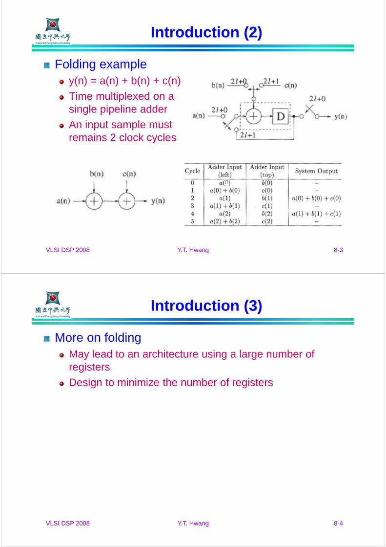
Folding exampley(n) = a(n) + b(n) + c(n)
Time multiplexed on a single pipeline adder
An input sample must remains 2 clock cycles
VLSI DSP 2008 Y.T. Hwang 8-4
Introduction (3)
More on foldingMay lead to an architecture using a large number of registers
Design to minimize the number of registers

VLSI DSP 2008 Y.T. Hwang 8-5
Folding transformation (1)
PreliminaryConsider a DFG
An edge e connecting nodes U and V with w(e) delays
Executions of the l-th iterations of U and V at time units Nl+u and Nl+v
u and v: folding orders and 0 ≤ u,v ≤ N-1
N: folding factor, the number of operations folded to a single function unit
HU and HV: function units to execute nodes U and V
HU is pipelined by PU stages
VLSI DSP 2008 Y.T. Hwang 8-6
Folding transformation (2)
Folding an edgehas w(e) delays
l-th iteration of node U is available at time Nl + u + PU
Generated data is used by the (l+w(e))-th iteration of V
The result must be stored for
VU e
uvPeNwuPNlvewlNVUD UUe
F )(][]))(([)(
Folding factor = N
VLSI DSP 2008 Y.T. Hwang 8-7
Folding transformation (3)
Folding setAn order of operations executed by the same hardware
Example: S1 = {A1,Ø ,A2}
A1: (S1|0), A2: (S1|2)
Biquad filter exampleAddition : 1 u.t. and 1-stage pipelining, PA = 1
Multiplication: 2 u.t. and 2-stage pipelining, PM = 2
Folding factor N = 4
Assume folding set S1 = {4, 2, 3, 1}, S2 = {5, 8, 6, 7}
VLSI DSP 2008 Y.T. Hwang 8-8
Folding transformation (4)
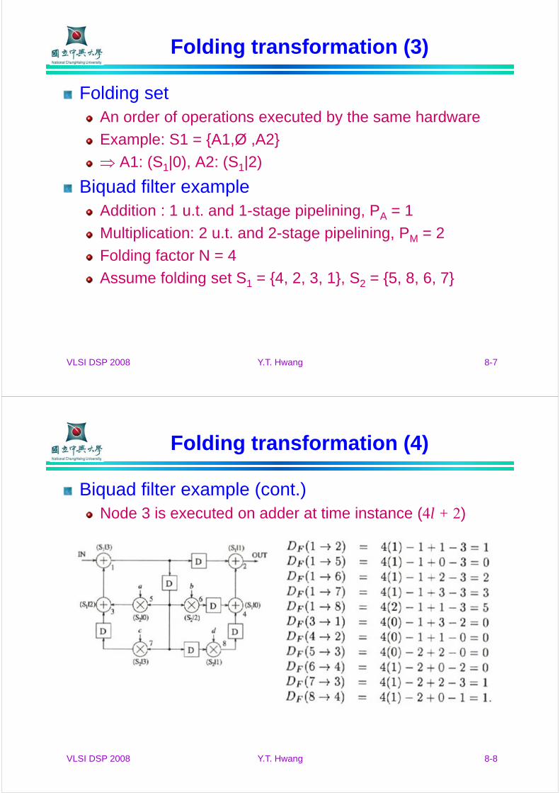
Biquad filter example (cont.)Node 3 is executed on adder at time instance (4l + 2)
VLSI DSP 2008 Y.T. Hwang 8-9
Folding transformation (5)
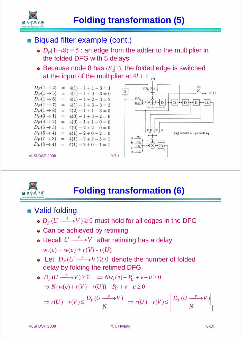
Biquad filter example (cont.)DF(1→8) = 5 : an edge from the adder to the multiplier in the folded DFG with 5 delays
Because node 8 has (S2|1), the folded edge is switched at the input of the multiplier at 4l + 1
VLSI DSP 2008 Y.T. Hwang 8-10
Folding transformation (6)
Valid foldingmust hold for all edges in the DFG
Can be achieved by retiming
Recall after retiming has a delay
wr(e) = w(e) + r(V) - r(U)
Let denote the number of folded delay by folding the retimed DFG
0)( VUD eF
VU e
0)(' VUD eF
N
VUDVrUr
N
VUDVrUr
uvPUrVrewN
uvPeNwVUD
eF
eF
U
Ure
F
)()()(
)()()(
0))()()((
0)( 0)('
VLSI DSP 2008 Y.T. Hwang 8-11
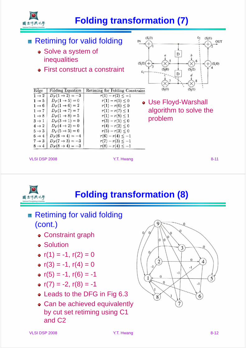
Folding transformation (7)
Retiming for valid foldingSolve a system of inequalities
First construct a constraint
Use Floyd-Warshall algorithm to solve the problem
VLSI DSP 2008 Y.T. Hwang 8-12
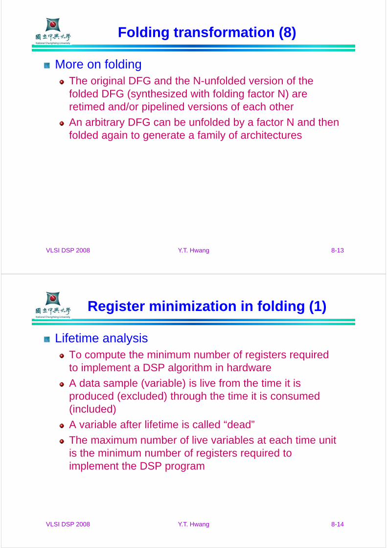
Folding transformation (8)
Retiming for valid folding (cont.)
Constraint graph
Solution
r(1) = -1, r(2) = 0
r(3) = -1, r(4) = 0
r(5) = -1, r(6) = -1
r(7) = -2, r(8) = -1
Leads to the DFG in Fig 6.3
Can be achieved equivalently by cut set retiming using C1 and C2
VLSI DSP 2008 Y.T. Hwang 8-13
Folding transformation (8)
More on foldingThe original DFG and the N-unfolded version of the folded DFG (synthesized with folding factor N) are retimed and/or pipelined versions of each other
An arbitrary DFG can be unfolded by a factor N and then folded again to generate a family of architectures
VLSI DSP 2008 Y.T. Hwang 8-14
Register minimization in folding (1)
Lifetime analysisTo compute the minimum number of registers required to implement a DSP algorithm in hardware
A data sample (variable) is live from the time it is produced (excluded) through the time it is consumed (included)
A variable after lifetime is called “dead”
The maximum number of live variables at each time unit is the minimum number of registers required to implement the DSP program
VLSI DSP 2008 Y.T. Hwang 8-15
Register minimization in folding (2)
ExampleAssume 3 variables a, b, c
Life time of variable a: {1,2,3,4}
Life time of variable b: {2,3,4,5,6,7}
Life time of variable c: {5,6,7}
Number of live variables {1,2,2,2,2,2,2}
2 registers are needed to implement the DSP program
VLSI DSP 2008 Y.T. Hwang 8-16
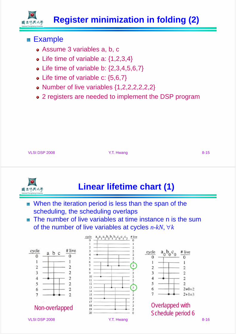
Linear lifetime chart (1)
When the iteration period is less than the span of the scheduling, the scheduling overlapsThe number of live variables at time instance n is the sum of the number of live variables at cycles n-kN, k
Non-overlapped Overlapped withSchedule period 6

VLSI DSP 2008 Y.T. Hwang 8-17
Linear lifetime chart (2)
Matrix transpose example
Assume row-wise access
Input time: Tinput
Zero latency output time: Tzlout
Tdiff = Tzlout – Tinput
Required latency Tlat = magnitude of the most negative value of Tdiff
Toutput = Tzlout + Tlat
ifc
heb
gda
ihg
fed
cba
VLSI DSP 2008 Y.T. Hwang 8-18
Linear lifetime chart (3)
Matrix transpose example (cont.)Assume iteration period of the DSP program is N = 9
VLSI DSP 2008 Y.T. Hwang 8-19
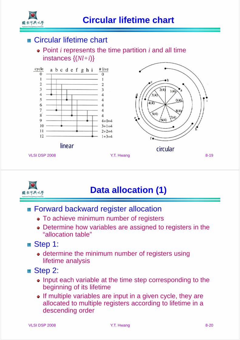
Circular lifetime chart
Circular lifetime chartPoint i represents the time partition i and all time instances {(Nl+i)}
linear circular
VLSI DSP 2008 Y.T. Hwang 8-20
Data allocation (1)
Forward backward register allocationTo achieve minimum number of registersDetermine how variables are assigned to registers in the “allocation table”
Step 1: determine the minimum number of registers using lifetime analysis
Step 2: Input each variable at the time step corresponding to the beginning of its lifetimeIf multiple variables are input in a given cycle, they are allocated to multiple registers according to lifetime in a descending order
VLSI DSP 2008 Y.T. Hwang 8-21
Data allocation (2)
Forward allocationIf register i holds the variable in the current cycle, then register i+1 holds the same variable in the next cycleIf the register i+1 is not available, then the variable is allocated to the first available forward register
Step 3:Each register is allocated in a forward manner until it is dead or reaches the last register
Step 4:In periodic scheduling, the allocation of current iteration also repeats itself in subsequent iterationsIf Rj is occupied by a variable in cycle l, hash the position for Rj at time unit l+N
VLSI DSP 2008 Y.T. Hwang 8-22
Data allocation (3)
Step 5:For a variable that reaches the last register and is not yet dead, allocate it in backward manner
If multiple registers available, choose the one with least but sufficient number of forward registers capable of completing the allocation
After a variable has been allocated backward, allocate it in a forward manner until it is dead or again reaches the last register
Step 6:Repeat step 4 and 5 as required until the allocation is complete

VLSI DSP 2008 Y.T. Hwang 8-23
Data allocation (4)
3X3 matrix transpose example with N = 9
After steps 1~4 completion
hashing
VLSI DSP 2008 Y.T. Hwang 8-24
Data allocation (5)
Another example
Linear lifetime chart
Step 1~4 completion
VLSI DSP 2008 Y.T. Hwang 8-25
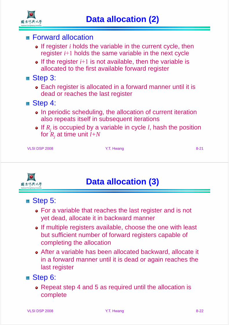
Data allocation (6)
architecture design after register allocation
VLSI DSP 2008 Y.T. Hwang 8-26
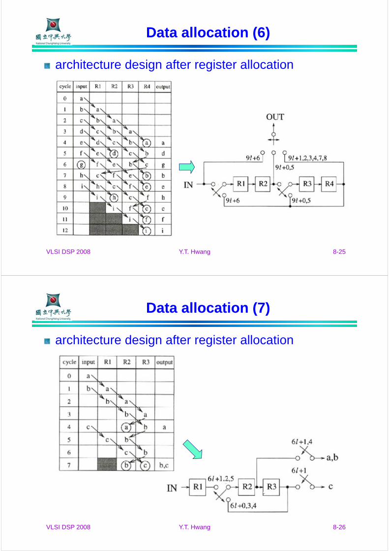
Data allocation (7)
architecture design after register allocation
VLSI DSP 2008 Y.T. Hwang 8-27
Register minimization in folding
GoalTo synthesize control circuits in folded architectures with minimum number of registers
ProceduresPerform retiming for folding
Write folding equations
Use the folding equations to construct a lifetime table
Draw the lifetime chart and determine the required number of registers
Perform forward-backward register allocation
Draw the folded architecture that uses the minimum number of registers
VLSI DSP 2008 Y.T. Hwang 8-28
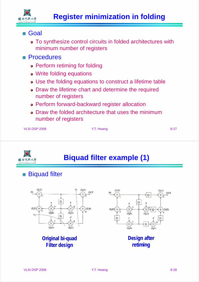
Biquad filter example (1)
Biquad filter
Original bi-quadFilter design
Design afterretiming
VLSI DSP 2008 Y.T. Hwang 8-29
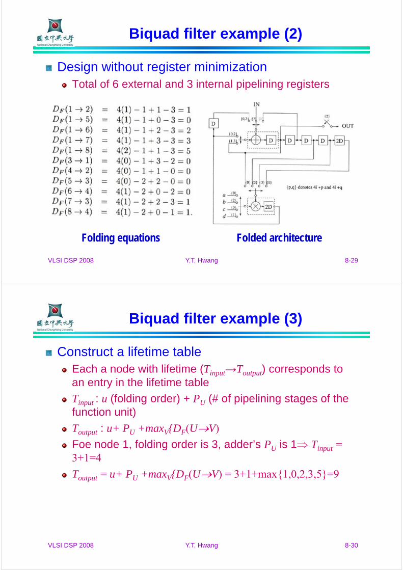
Biquad filter example (2)
Design without register minimizationTotal of 6 external and 3 internal pipelining registers
Folding equations Folded architecture
VLSI DSP 2008 Y.T. Hwang 8-30
Biquad filter example (3)
Construct a lifetime tableEach a node with lifetime (Tinput→Toutput) corresponds to an entry in the lifetime table
Tinput : u (folding order) + PU (# of pipelining stages of the function unit)
Toutput : u+ PU +maxV{DF(UV)
Foe node 1, folding order is 3, adder’s PU is 1 Tinput = 3+1=4
Toutput = u+ PU +maxV{DF(UV) = 3+1+max{1,0,2,3,5}=9
VLSI DSP 2008 Y.T. Hwang 8-31
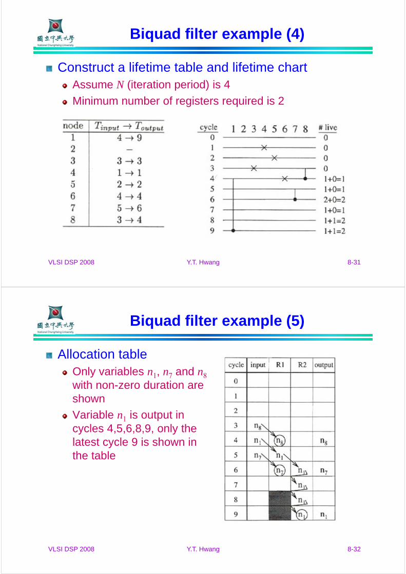
Biquad filter example (4)
Construct a lifetime table and lifetime chartAssume N (iteration period) is 4
Minimum number of registers required is 2
VLSI DSP 2008 Y.T. Hwang 8-32
Biquad filter example (5)
Allocation tableOnly variables n1, n7 and n8
with non-zero duration are shown
Variable n1 is output in cycles 4,5,6,8,9, only the latest cycle 9 is shown in the table
VLSI DSP 2008 Y.T. Hwang 8-33
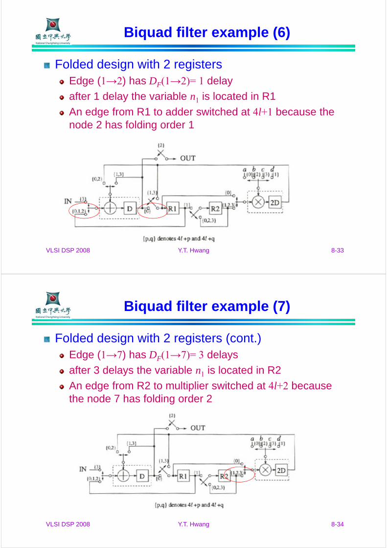
Biquad filter example (6)
Folded design with 2 registersEdge (1→2) has DF(1→2)= 1 delay
after 1 delay the variable n1 is located in R1
An edge from R1 to adder switched at 4l+1 because the node 2 has folding order 1
VLSI DSP 2008 Y.T. Hwang 8-34
Biquad filter example (7)
Folded design with 2 registers (cont.)Edge (1→7) has DF(1→7)= 3 delays
after 3 delays the variable n1 is located in R2
An edge from R2 to multiplier switched at 4l+2 because the node 7 has folding order 2

VLSI DSP 2008 Y.T. Hwang 8-35
IIR filter example (1)
IIR filter before retimingy(n) = ay(n-3) + by(n-5) + x(n)
Folding factor = 2
Folding set: ADD S1 = {1,2}, MPY S2 = {4,3}
Retiming solution
r(1) = 0, r(2) = 0, r(3) = -2, r(4) = -1
VLSI DSP 2008 Y.T. Hwang 8-36
IIR filter example (2)
IIR filter after retiming
Folding equations for the retimed DFG
DF(1→2)= 2(0) − 1 + 1 − 0 = 0
DF(2→3)= 2(3) − 1 + 1 − 1 = 5
DF(2→4)= 2(2) − 1 + 0 − 1 = 2
DF(3→1)= 2(2) − 2 + 0 − 1 = 1
DF(4→1)= 2(1) − 2 + 0 − 0 = 0
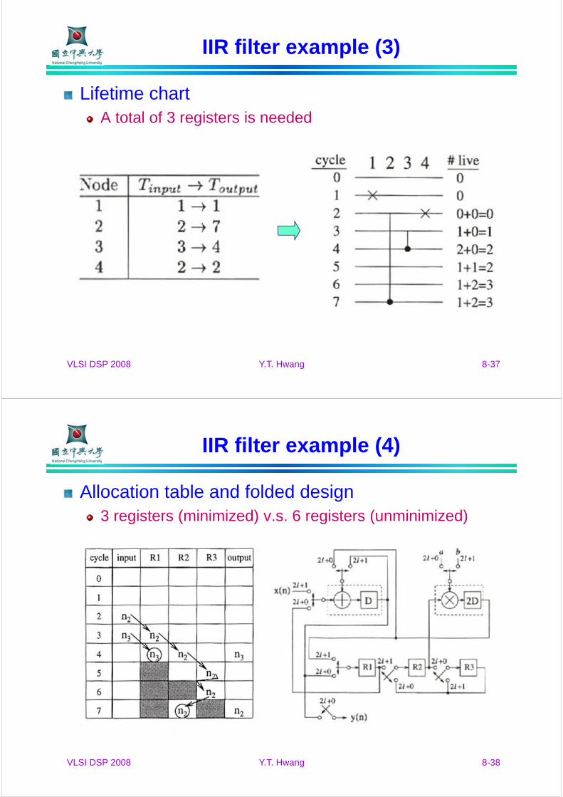
Lifetime table
VLSI DSP 2008 Y.T. Hwang 8-37
IIR filter example (3)
Lifetime chartA total of 3 registers is needed
VLSI DSP 2008 Y.T. Hwang 8-38
IIR filter example (4)
Allocation table and folded design3 registers (minimized) v.s. 6 registers (unminimized)
VLSI DSP 2008 Y.T. Hwang 8-39
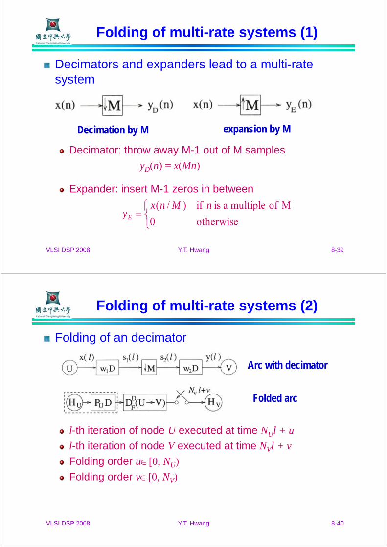
Folding of multi-rate systems (1)
Decimators and expanders lead to a multi-rate system
Decimator: throw away M-1 out of M samples
yD(n) = x(Mn)
Expander: insert M-1 zeros in between
Decimation by M expansion by M
otherwise0
M of multiple a is if)/( nMnxyE
VLSI DSP 2008 Y.T. Hwang 8-40
Folding of multi-rate systems (2)
Folding of an decimator
l-th iteration of node U executed at time NUl + u
l-th iteration of node V executed at time NVl + v
Folding order u[0, NU)
Folding order v[0, NV)
Arc with decimator
Folded arc

VLSI DSP 2008 Y.T. Hwang 8-41
Folding of multi-rate systems (3)
Folding of an decimator (cont.)Sample y(l) consumed during the l-th iteration of V is produced during the (Ml−(Mw2+w1))-th iteration of U
y(l) is consumed by HV in time unit NVl + v
generated by HU in time unit NU(Ml−(Mw2+w1))+u+PU
y(l) must be stored for
))(()()(
)()()(
)()(
1222
112
11
wwlMxwlsly
wMlxMlsls
wlxls
uvPwMwNlMNN
PuwMwMlNvlNVUD
UUUV
UUVDF
)()(
]))(([][)(
12
12
VLSI DSP 2008 Y.T. Hwang 8-42
Folding of multi-rate systems (4)
Folding of an decimator (cont.)In a decimator, NV = MNU
Node U executes M times for each execution of node V
uvPwMwNVUD UUDF )()( 12
VLSI DSP 2008 Y.T. Hwang 8-43
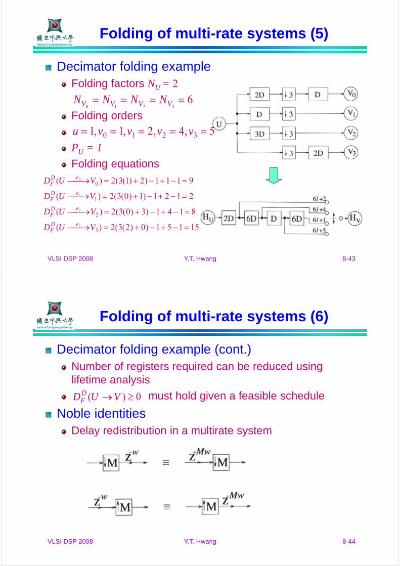
Folding of multi-rate systems (5)
Decimator folding exampleFolding factors NU = 2
Folding orders
PU = 1
Folding equations
63210 VVVV NNNN
5,4,2,1,1 3210 vvvvu
15151)0)2(3(2)(
8141)3)0(3(2)(
2121)1)0(3(2)(
9111)2)1(3(2)(
3
2
1
0
3
2
1
0
VUD
VUD
VUD
VUD
eDF
eDF
eDF
eDF
VLSI DSP 2008 Y.T. Hwang 8-44
Folding of multi-rate systems (6)
Decimator folding example (cont.)Number of registers required can be reduced using lifetime analysis
must hold given a feasible schedule
Noble identitiesDelay redistribution in a multirate system
0)( VUDDF
VLSI DSP 2008 Y.T. Hwang 8-45
Folding of multi-rate systems (7)
Retiming of multi-rate DFGLet w’1 and w’2 be the number of delays on arc U→Vafter retiming
r(u), r(v): retiming values of nodes U and V, respectively
r(Duv): number of times one delays removed from its output, and M delays are added to its input
U
DF
U
DF
UDF
UuvuvUD
F
uv
uv
UUD
F
N
VUDVMrUr
N
VUDVMrUr
UrVMrNVUD
uvPUrDMrwDrVrwMNVUD
DrVrww
UrDMrww
uvPwMwNVUD
)()()(
)()()(
0))()(()(
)]()())()(([)(
)()(
)()( where
)()(
12'
2'2
1'1
'1
'2
'
VLSI DSP 2008 Y.T. Hwang 8-46
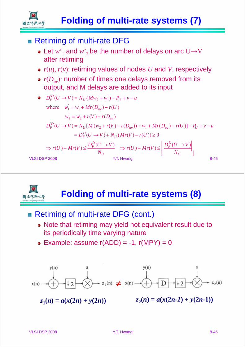
Folding of multi-rate systems (8)
Retiming of multi-rate DFG (cont.)Note that retiming may yield not equivalent result due to its periodically time varying nature
Example: assume r(ADD) = -1, r(MPY) = 0
z1(n) = a(x(2n) + y(2n)) z2(n) = a(x(2n-1) + y(2n-1))