chapter 7: unplanted drying beds
TRANSCRIPT
Tech
nolo
gy
141
Chapter 7
Unplanted Drying BedsPierre-Henri Dodane and Mariska Ronteltap
Learning Objectives
• Have an understanding of an unplanted drying bed for sludge dewatering.
• Have an overview of the main components of unplanted drying beds, their characteristics and their effect on the performance of the beds.
• Know the appropriate level of operational and maintenance monitoring necessary for the operation of unplanted drying beds.
• Be able to design an unplanted drying bed to achieve the desired treatment objectives.
7.1 INTRODUCTION
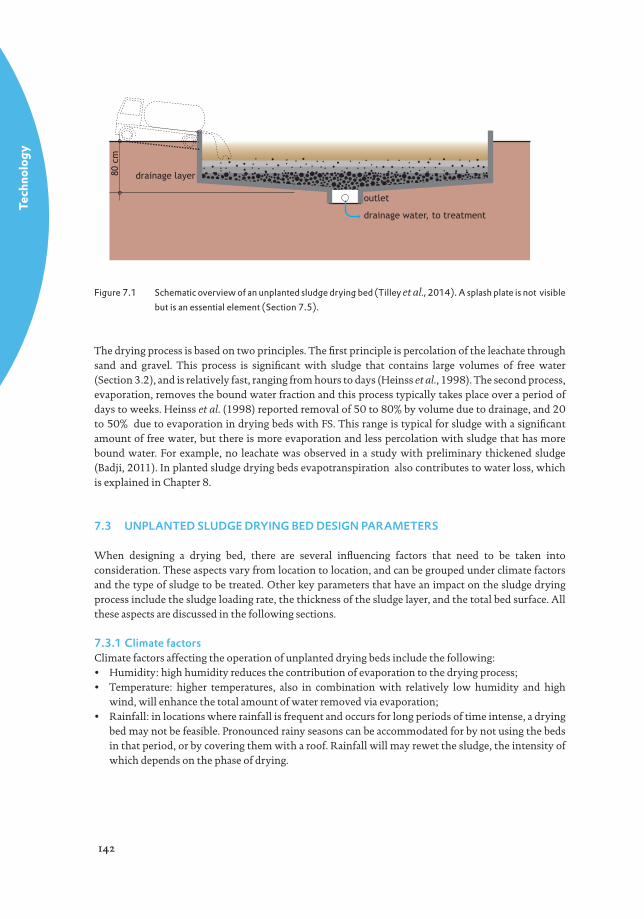
Unplanted sludge drying beds are shallow fi lters fi lled with sand and gravel with an under-drain at the bottom to collect leachate. Sludge is discharged onto the surface for dewatering (Figure 7.1). The drying process in a drying bed is based on drainage of liquid through the sand and gravel to the bottom of the bed, and evaporation of water from the surface of the sludge to the air. The design as well as the operation of the drying bed is fairly straightforward, provided the sludge loading rate is well selected and the inlet points for depositing the sludge onto the bed are properly designed. Depending on the faecal sludge (FS) characteristics, a variable fraction of approximately 50-80% of the sludge volume drains off as a liquid (or leachate), which needs to be collected and treated prior to discharge (Tilley et al., 2014). After reaching the desired dryness, the sludge is removed from the bed manually or mechanically. Further processing for stabilisation and pathogen reduction may be required depending on the intended enduse option. When considering the installation of a drying bed, the ease of operation and low cost needs to be considered against the relatively large footprint and odour potential.
7.2 TREATMENT PRINCIPLE
A FS treatment plant (FSTP) consists of several drying beds in one location. Sludge is deposited on each of these drying beds where it remains until the desired moisture content is achieved. It is subsequently mechanically or manually removed for disposal or further treatment and reuse.
Tech
nolo
gy
142
drainage water, to treatment
outlet
drainage layer80 c
m
Figure 7.1 Schematic overview of an unplanted sludge drying bed (Tilley et al., 2014). A splash plate is not visible but is an essential element (Section 7.5).
The drying process is based on two principles. The fi rst principle is percolation of the leachate through sand and gravel. This process is signifi cant with sludge that contains large volumes of free water (Section 3.2), and is relatively fast, ranging from hours to days (Heinss et al., 1998). The second process, evaporation, removes the bound water fraction and this process typically takes place over a period of days to weeks. Heinss et al. (1998) reported removal of 50 to 80% by volume due to drainage, and 20 to 50% due to evaporation in drying beds with FS. This range is typical for sludge with a signifi cant amount of free water, but there is more evaporation and less percolation with sludge that has more bound water. For example, no leachate was observed in a study with preliminary thickened sludge (Badji, 2011). In planted sludge drying beds evapotranspiration also contributes to water loss, which is explained in Chapter 8.
7.3 UNPLANTED SLUDGE DRYING BED DESIGN PARAMETERS
When designing a drying bed, there are several infl uencing factors that need to be taken into consideration. These aspects vary from location to location, and can be grouped under climate factors and the type of sludge to be treated. Other key parameters that have an impact on the sludge drying process include the sludge loading rate, the thickness of the sludge layer, and the total bed surface. All these aspects are discussed in the following sections.
7.3.1 Climate factorsClimate factors affecting the operation of unplanted drying beds include the following:• Humidity: high humidity reduces the contribution of evaporation to the drying process;• Temperature: higher temperatures, also in combination with relatively low humidity and high
wind, will enhance the total amount of water removed via evaporation;• Rainfall: in locations where rainfall is frequent and occurs for long periods of time intense, a drying
bed may not be feasible. Pronounced rainy seasons can be accommodated for by not using the beds in that period, or by covering them with a roof. Rainfall will may rewet the sludge, the intensity of which depends on the phase of drying.
Tech
nolo
gy
143
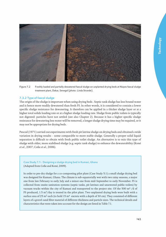
Figure 7.2 Freshly loaded and partially dewatered faecal sludge on unplanted drying beds at Niayes faecal sludge treatment plant, Dakar, Senegal (photo: Linda Strande).
7.3.2 Type of faecal sludgeThe origin of the sludge is important when using drying beds . Septic tank sludge has less bound water and is hence more readily dewatered than fresh FS. In other words, it is considered to contain a lower specifi c sludge resistance for dewatering. It therefore can be applied in a thicker sludge layer or at a higher total solids loading rate or at a higher sludge loading rate. Sludge from public toilets is typically not digested: particles have not settled (see also Chapter 2). Because it has a higher specifi c sludge resistance for dewatering less water will be removed, a longer sludge drying time may be required, or it may not be appropriate for drying beds.
Pescod (1971) carried out experiments with fresh pit latrine sludge on drying beds and obtained a wide variation in drying results – some comparable to more stable sludge. Generally a proper solid liquid separation is diffi cult to obtain with fresh public toilet sludge. An alternative is to mix this type of sludge with older, more stabilised sludge (e.g. septic tank sludge) to enhance the dewaterability (Koné et al., 2007; Cofi e et al., 2006).
Case Study 7.1: Designing a sludge drying bed in Kumasi, Ghana(Adapted from Cofi e and Koné, 2009).
In order to pre-dry sludge for a co-composting pilot plant (Case Study 5.1) a small sludge drying bed
was designed for Kumasi, Ghana. The climate is sub-equatorially wet with two rainy seasons, a major
one from late February to early July and a minor one from mid-September to early November. FS is
collected from onsite sanitation systems (septic tanks, pit latrines and unsewered public-toilets) by
vacuum trucks within the city of Kumasi and transported to the project site. Of the 500 m³/d of
FS produced, 1.5 m3/day is treated in the pilot plant. Two unplanted drying beds were built with a
surface area of 25 m2 each (to hold 15 m³ excreta with a depth of 30 cm). They consisted of different
layers of a gravel-sand fi lter material of different thickness and particle sizes. The technical details and
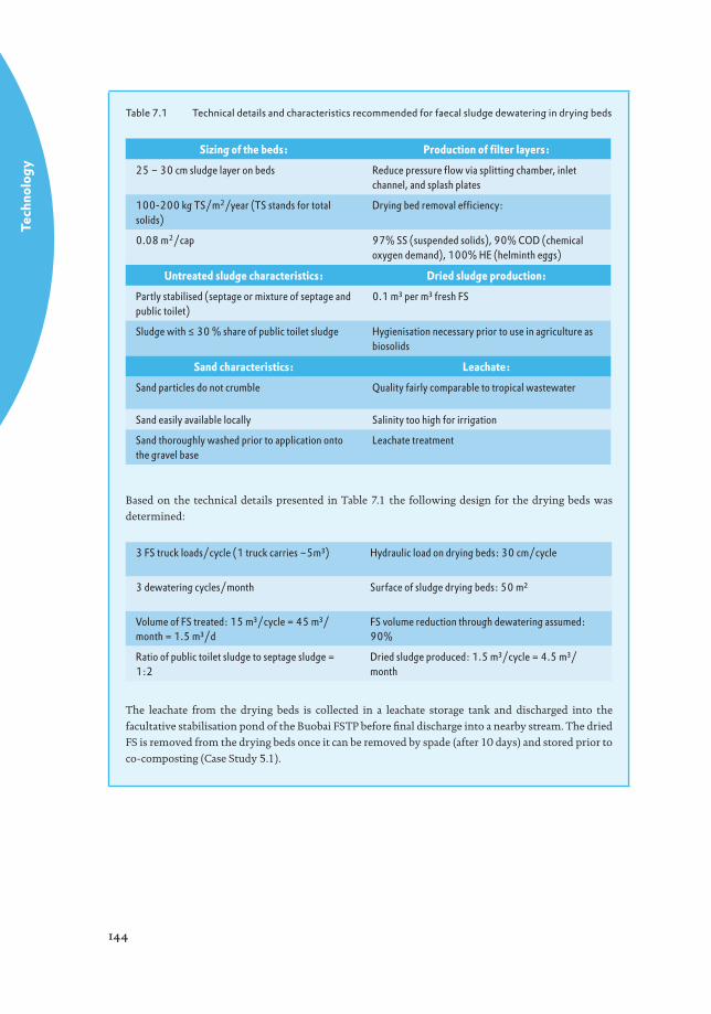
characteristics that were taken into account for the design are listed in Table 7.1.
Tech
nolo
gy
144
Table 7.1 Technical details and characteristics recommended for faecal sludge dewatering in drying beds
Sizing of the beds: Production of fi lter layers:
25 – 30 cm sludge layer on beds Reduce pressure fl ow via splitting chamber, inlet channel, and splash plates
100-200 kg TS/m2/year (TS stands for total solids)
Drying bed removal effi ciency:
0.08 m2/cap 97% SS (suspended solids), 90% COD (chemical oxygen demand), 100% HE (helminth eggs)
Untreated sludge characteristics: Dried sludge production:
Partly stabilised (septage or mixture of septage and public toilet)
0.1 m³ per m³ fresh FS
Sludge with ≤ 30 % share of public toilet sludge Hygienisation necessary prior to use in agriculture as biosolids
Sand characteristics: Leachate:
Sand particles do not crumble Quality fairly comparable to tropical wastewater
Sand easily available locally Salinity too high for irrigation
Sand thoroughly washed prior to application onto the gravel base
Leachate treatment
Based on the technical details presented in Table 7.1 the following design for the drying beds was
determined:
3 FS truck loads/cycle (1 truck carries ~5m³) Hydraulic load on drying beds: 30 cm/cycle
3 dewatering cycles/month Surface of sludge drying beds: 50 m²
Volume of FS treated: 15 m³/cycle = 45 m³/month = 1.5 m³/d
FS volume reduction through dewatering assumed: 90%
Ratio of public toilet sludge to septage sludge = 1:2
Dried sludge produced: 1.5 m³/cycle = 4.5 m³/month
The leachate from the drying beds is collected in a leachate storage tank and discharged into the
facultative stabilisation pond of the Buobai FSTP before fi nal discharge into a nearby stream. The dried
FS is removed from the drying beds once it can be removed by spade (after 10 days) and stored prior to
co-composting (Case Study 5.1).
Tech
nolo
gy
145
7.3.3 Sludge loading rateThe sludge loading rate (SLR) is expressed in kg TS/ m2/year. It represents the mass of solids dried on one m2 of bed in one year. Pescod (1971) states that any general number linking the total amount of sludge to be dried to a sludge loading rate, bed surface area and loading depth can only be an estimate, as the local conditions vary greatly. However, it is possible to indicate a range of sludge loading rates which typically vary between 100 and 200 kg TS/m2/year in tropical climates, with 100 for poorer conditions and 200 for optimal conditions, while approximately 50 kg SS/m2/year is commonly used in temperate climates in Europe (Duchêne, 1990). Poor conditions entail high humidity, low temperature, long periods of rainfall, and/or a large proportion of fresh FS. Optimal conditions comprise a low humidity, high temperature, a low amount of precipitation, and stabilised sludge. It may be possible in some cases to achieve an even higher sludge loading rate. Cofi e et al. (2006) for example applied sludge at a loading rate of up to 300 kg TS/m2/year. Badji (2011) also found a SLR of 300 kg TS/m2/year to be effective for dewatering thickened FS with 60 g TS/L, while about 150 kg TS/m2/year was estimated to be an effective rate for a FS with 5 g TS/L in the same climatic conditions. Optimal local operating conditions need to be determined through pilot-scale experiments.
7.3.4 Thickness of the sludge layerA review of the literature shows that sludge is typically applied in a layer of 20 to 30 cm in depth, with a preference for 20 cm. It may seem a better option to apply a thicker sludge layer as more sludge can be applied to one bed; however, this will result in an increased drying time, and a reduction in the number of times the bed can be used per year. For any particular sludge dried under the same weather conditions, Pescod (1971) found that an increase in the sludge layer of only 10 cm prolonged the necessary drying time by 50 to 100%.
It is also important that the sidewalls of the drying beds are high enough to accommodate different loadings. For example, if a layer of 20 cm is applied with a water content of 90%, the initial height before the water is drained-off will be much greater than 20 cm. If the beds receive sludge discharged from a truck as opposed to settling tanks, the walls need to be higher than the planned 20 to 30 cm of sludge layer to allow for the increased volume of liquid.
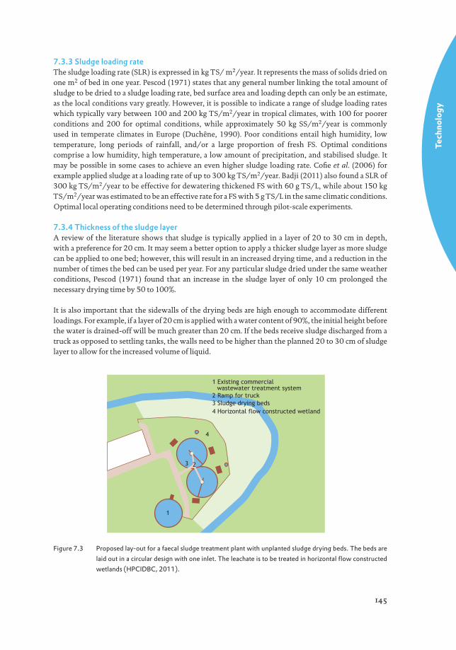
1 Existing commercial wastewater treatment system2 Ramp for truck3 Sludge drying beds4 Horizontal flow constructed wetland
1
23
4
Figure 7.3 Proposed lay-out for a faecal sludge treatment plant with unplanted sludge drying beds. The beds are laid out in a circular design with one inlet. The leachate is to be treated in horizontal fl ow constructed wetlands (HPCIDBC, 2011).
Tech
nolo
gy
146
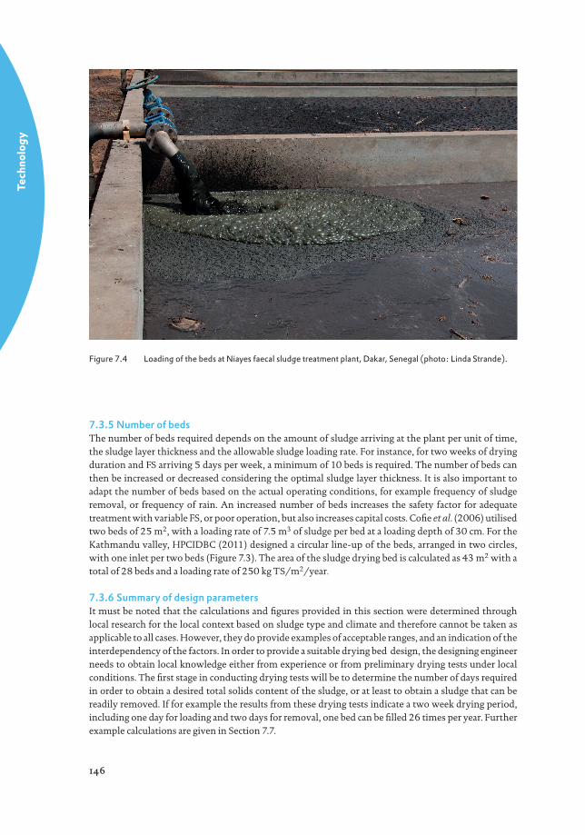
Figure 7.4 Loading of the beds at Niayes faecal sludge treatment plant, Dakar, Senegal (photo: Linda Strande).
7.3.5 Number of bedsThe number of beds required depends on the amount of sludge arriving at the plant per unit of time, the sludge layer thickness and the allowable sludge loading rate. For instance, for two weeks of drying duration and FS arriving 5 days per week, a minimum of 10 beds is required. The number of beds can then be increased or decreased considering the optimal sludge layer thickness. It is also important to adapt the number of beds based on the actual operating conditions, for example frequency of sludge removal, or frequency of rain. An increased number of beds increases the safety factor for adequate treatment with variable FS, or poor operation, but also increases capital costs. Cofi e et al. (2006) utilised two beds of 25 m2, with a loading rate of 7.5 m3 of sludge per bed at a loading depth of 30 cm. For the Kathmandu valley, HPCIDBC (2011) designed a circular line-up of the beds, arranged in two circles, with one inlet per two beds (Figure 7.3). The area of the sludge drying bed is calculated as 43 m2 with a total of 28 beds and a loading rate of 250 kg TS/m2/year.
7.3.6 Summary of design parametersIt must be noted that the calculations and fi gures provided in this section were determined through local research for the local context based on sludge type and climate and therefore cannot be taken as applicable to all cases. However, they do provide examples of acceptable ranges, and an indication of the interdependency of the factors. In order to provide a suitable drying bed design, the designing engineer needs to obtain local knowledge either from experience or from preliminary drying tests under local conditions. The fi rst stage in conducting drying tests will be to determine the number of days required in order to obtain a desired total solids content of the sludge, or at least to obtain a sludge that can be readily removed. If for example the results from these drying tests indicate a two week drying period, including one day for loading and two days for removal, one bed can be fi lled 26 times per year. Further example calculations are given in Section 7.7.
Tech
nolo
gy
147
7.4 CONSTRUCTION OF AN UNPLANTED SLUDGE DRYING BED
A drying bed treatment facility consists of the beds with an inlet and an outlet, a leachate collection and drainage system, a designated area outside of the beds for storage and continued drying of the sludge, and potentially settling-thickening tanks. Sludge can be loaded directly from trucks onto the beds. In this case, various confi gurations exist such as creating one inlet for two beds, with a splitter to divide the sludge between the beds (Cofi e et al., 2006), by designing the bed with a ramp for the inlet of the sludge. Alternatively, a holding or settling tank can be installed into which the sludge is fi rst discharged before being pumped into the drying beds. A splash plate must be used to prevent erosion of the sand layer and to allow even distribution of the sludge (Tilley et al., 2008). This is crucial, as without a splash plate, the sand layer would be destroyed during the very fi rst loading operation. Bar screens at the inlet are essential to keep rubble and trash present in the sludge from entering the bed. This is important to allow for proper use or disposal of the sludge after drying. The drying bed is typically a rectangular shape excavated from the soil, with a sealed bottom. As was shown in Figure 7.1, the bottom of the bed slopes downwards towards where the drainage system is is installed such that the leachate can drain to the discharging point or further treatment. As the leachate is high in suspended solids, organic material, and nutrients, it needs to be treated before it can be discharged to the environment, according to the quality required for reclamation or for receiving water bodies (see Chapter 10 for further details).
7.4.1 Gravel and sandLayers of gravel and sand are applied on top of the drainage system. When constructing drying beds, it is essential to use washed sand and gravel in order to prevent clogging of the bed from fi ne particles. This is important both for the initial construction, and for further supplemental additions of sand. The gravel layers function as a support and there are typically two or three layers with two different diameters of gravel (Figure 7.1). The distribution of diameter size in the layers is based on avoiding clogging from small particles washing into the drain. The lower layer usually contains coarser gravel with a diameter of around 20-40 mm and the intermediate layer contains fi ner gravel with a diameter between the coarse gravel and the upper sand layer, for example 5-15 mm. Locally available materials will also have an infl uence on the design. For example, Cofi e et al. (2006) made use of gravel with a diameter of 19 mm applied in a 15 cm supporting layer underneath 10 cm of gravel with a 10 mm diameter. To avoid the migration of particles from the sand layer into the gravel layers, a third layer of small gravel can also be used according to what is locally available, for example 2-6 mm.
A sand layer is placed on top of the gravel. The sand layer enhances drainage and prevents clogging, as it keeps the sludge from lodging in the pore spaces of the gravel. The diameter of the sand is crucial as sand with a larger diameter (1.0-1.5 mm) can result in the relatively fast accumulation of organic matter, thereby increasing the risk of clogging, This risk is reduced if sand with a smaller diameter (0.1-0.5 mm) is used (Kuffour et al., 2009).
When selecting sand for the bed, it is important to note that the sand will need to be replaced occasionally, as a certain amount of the sand is bound to the sludge and will therefore be removed when the sludge is removed. It is therefore recommended that the sand that is chosen is easily obtained. Duchène (1990) reported a loss of a few centimetres of sand for each 5-10 drying sequences, whereas at the Cambérène FSTP in Dakar 5 cm is lost after 25 drying sequences (Badji, 2008).
The sand also needs to be replaced when there is a build-up of organic matter and the bed starts to clog. Kuffour et al. (2009) observed a link between the rate of clogging and the rate of organic matter build-up on the sand. As organic matter builds up faster on sand with larger particles, a bed fi lled with larger diameter sand is more likely to clog. Cofi e et al. (2006) had to replace the sand twice in a series of 8 dewatering cycles over 10 months due to clogging in a pilot scale implementation. For a full scale
Tech
nolo
gy
148
application, HPCIDBC (2011) estimated a sand exchange period of three years at a sludge loading rate of 250 kg TS/m2/year, a sludge fi lling height of 20 cm and a one week drying period (applicable to Nepali conditions).
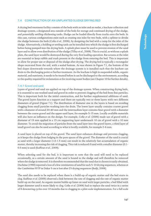
7.4.2 Sludge removalIn order for the sludge to be removed properly, it needs to be dry enough that it can be shovelled. Pescod (1971) carried out experiments with different types of sludge and treatment technologies, including lagoons and drying beds, and found sludge with a TS content of at least 25% fi t for removal. The drying time of a specifi c sludge type depends on a number of factors, one of which is the sludge dewatering resistance. The higher the sludge dewatering resistance, the lower the drainage rate which leads to a prolonged drainage time. Sludge is removed mechanically or manually, with shovels and wheel barrows being the most common manual method (Figure 7.5).
In order to remove the sludge, a ramp must be provided to allow wheel barrows or other equipment to access the bed. If a drier sludge is required, this can be achieved by evaporation after it is removed from the drying bed. The dried sludge is frequently stored in heaps for periods of up to one year, during which time pathogen reduction can occur. It is however, recommended that a more controlled treatment is employed in order to produce reliable and consistent endproducts.
Rewetting of the sludge is considered problematic if rainfall occurs before the free water of the sludge is completely drained. In this case, the moisture content of the sludge increases again and the drying period is prolonged. When the sludge is already dry enough to expose the sand layer through the cracks in the sludge, rain water can pass straight through the sludge and drains through the drying bed.
Figure 7.5 Removing sludge from unplanted drying beds at Cambérène treatment plant, Dakar, Senegal (photo: Linda Strande).
Tech
nolo
gy
149
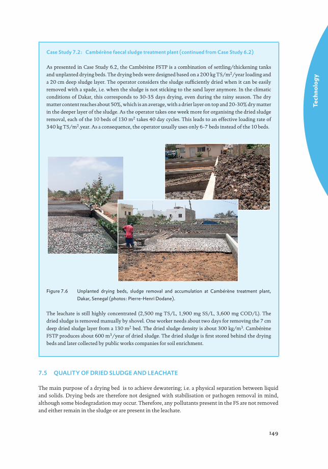
Case Study 7.2: Cambérène faecal sludge treatment plant (continued from Case Study 6.2)
As presented in Case Study 6.2, the Cambérène FSTP is a combination of settling/thickening tanks
and unplanted drying beds. The drying beds were designed based on a 200 kg TS/m2/year loading and
a 20 cm deep sludge layer. The operator considers the sludge suffi ciently dried when it can be easily
removed with a spade, i.e. when the sludge is not sticking to the sand layer anymore. In the climatic
conditions of Dakar, this corresponds to 30-35 days drying, even during the rainy season. The dry
matter content reaches about 50%, which is an average, with a drier layer on top and 20-30% dry matter
in the deeper layer of the sludge. As the operator takes one week more for organising the dried sludge
removal, each of the 10 beds of 130 m2 takes 40 day cycles. This leads to an effective loading rate of
340 kg TS/m2.year. As a consequence, the operator usually uses only 6-7 beds instead of the 10 beds.
Figure 7.6 Unplanted drying beds, sludge removal and accumulation at Cambérène treatment plant, Dakar, Senegal (photos: Pierre-Henri Dodane).
The leachate is still highly concentrated (2,500 mg TS/L, 1,900 mg SS/L, 3,600 mg COD/L). The
dried sludge is removed manually by shovel. One worker needs about two days for removing the 7 cm
deep dried sludge layer from a 130 m2 bed. The dried sludge density is about 300 kg/m3. Cambérène
FSTP produces about 600 m3/year of dried sludge. The dried sludge is fi rst stored behind the drying
beds and later collected by public works companies for soil enrichment.
7.5 QUALITY OF DRIED SLUDGE AND LEACHATE
The main purpose of a drying bed is to achieve dewatering; i.e. a physical separation between liquid and solids. Drying beds are therefore not designed with stabilisation or pathogen removal in mind, although some biodegradation may occur. Therefore, any pollutants present in the FS are not removed and either remain in the sludge or are present in the leachate.
Tech
nolo
gy
150
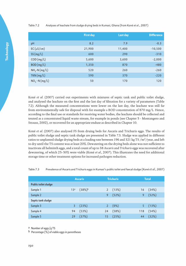
Table 7.2 Analyses of leachate from sludge drying beds in Kumasi, Ghana (from Koné et al., 2007)
First day Last day Difference
pH 8.2 7.9 -0.3
EC (µS/cm) 21,900 11,400 -10,500
SS (mg/L) 600 290 -310
COD (mg/L) 5,600 3,600 -2,000
BOD (mg/L) 1,350 870 -480
NH3-N (mg/L) 520 260 -260
TKN (mg/L) 590 370 -220
NO3--N (mg/L) 50 170 120
Koné et al. (2007) carried out experiments with mixtures of septic tank and public toilet sludge, and analysed the leachate on the fi rst and the last day of fi ltration for a variety of parameters (Table 7.2). Although the measured concentrations were lower on the last day, the leachate was still far from environmentally safe for disposal with for example a BOD concentration of 870 mg/L. Hence, according to the fi nal use or standards for receiving water bodies, the leachate should be collected and treated as a concentrated liquid waste stream, for example in ponds (see Chapter 5 - Montangero and Strauss, 2002), or recovered for an appropriate enduse as described in Chapter 10.
Koné et al. (2007) also analysed FS from druing beds for Ascaris and Trichuris eggs. The results of public toilet sludge and septic tank sludge are presented in Table 7.3. Sludge was applied in different ratios to unplanted sludge drying beds at a loading rate between 196 and 321 kg TS /m2/year, and left to dry until the TS content was at least 20%. Dewatering on the drying beds alone was not suffi cient to inactivate all helminth eggs, and a total count of up to 38 Ascaris and Trichuris eggs was recovered after dewatering, of which 25–50% were viable (Koné et al., 2007). This illustrates the need for additional storage time or other treatment options for increased pathogen reduction.
Table 7.3 Prevalence of Ascaris and Trichuris eggs in Kumasi’s public toilet and faecal sludge (Koné et al., 2007)
Ascaris Trichuris Total
Public toilet sludge
Sample 1 13a (38%)b 2 (13%) 16 (34%)
Sample 2 9 (52%) 9 (52%)
Septic tank sludge
Sample 3 3 (23%) 2 (0%) 5 (13%)
Sample 4 94 (53%) 24 (58%) 118 (54%)
Sample 5 29 (37%) 15 (25%) 44 (32%)
a Number of eggs/g TSb Percentage (%) of viable eggs in parentheses
Tech
nolo
gy
151
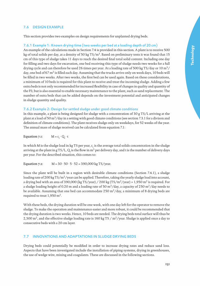
7.6 DESIGN EXAMPLE
This section provides two examples on design requirements for unplanted drying beds.
7.6.1 Example 1: Known drying time (two weeks per bed at a loading depth of 20 cm)An example of the calculations made in Section 7.4 is provided in this section. A plant is to receive 500 kg of total solids per day, at a density of 50 kg TS/m3. Based on preliminary tests it was found that 15 cm of this type of sludge takes 11 days to reach the desired fi nal total solid content. Including one day for fi lling and two days for excavation, one bed receiving this type of sludge needs two weeks for a full drying cycle and can therefore be used 26 times per year. At a loading rate of 500 kg TS/day or 10 m3/day, one bed of 67 m2 is fi lled each day. Assuming that the trucks arrive only on week days, 10 beds will be fi lled in two weeks. After two weeks, the fi rst bed can be used again. Based on these considerations, a minimum of 10 beds is required for this plant to receive and treat the incoming sludge. Adding a few extra beds is not only recommended for increased fl exibility in case of changes in quality and quantity of the FS; but is also essential to enable necessary maintenance to the plant, such as sand replacement. The number of extra beds that can be added depends on the investment potential and anticipated changes in sludge quantity and quality.
7.6.2 Example 2: Design for settled sludge under good climate conditions In this example, a plant is being designed for sludge with a concentration of 30 g TS/L arriving at the plant at a load of 50 m3/day in a setting with good climate conditions (see section 7.3.1 for a divison and defi nition of climate conditions). The plant receives sludge only on weekdays, for 52 weeks of the year. The annual mass of sludge received can be calculated from equation 7.1: Equation 7.1: M = ci . Qi . t
In which M is the sludge load in kg TS per year, ci is the average total solids concentration in the sludge arriving at the plant in g TS/L, Qi is the fl ow in m3 per delivery day, and t is the number of delivery days per year. For the described situation, this comes to:
Equation 7.2: M = 30 . 50 . 5 . 52 = 390,000 kg TS/year.
Since the plant will be built in a region with desirable climate conditions (Section 7.4.1), a sludge loading rate of 200 kg TS/m2/year can be applied. Therefore, taking the yearly sludge load into account, a drying bed with an area of 390,000 (kg TS/year) / 200 kg (TS/m2/year) = 1,950 m2 is required. For a sludge loading height of 0.20 m and a loading rate of 50 m3/day, a capacity of 250 m2/day needs to be available. Assuming that one bed can accommodate 250 m2/day, a minimum of 8 drying beds are required to treat 1,950 m2.
With these beds, the drying duration will be one week, with one day left for the operator to remove the sludge. To make the operation and maintenance easier and more robust, it could be recommended that the drying duration is two weeks. Hence, 10 beds are needed. The drying beds total surface will thus be 2,500 m2, and the effective sludge loading rate is 160 kg TS / m2/year. Sludge is applied once a day to consecutive beds with a 20 cm layer.
7.7 INNOVATIONS AND ADAPTATIONS IN SLUDGE DRYING BEDS
Drying beds could potentially be modifi ed in order to increase drying rates and reduce sand loss. Aspects that have been investigated include the installation of piping systems, drying in greenhouses, the use of wedge wire, mixing and coagulants. These are discussed in the following sections.
Tech
nolo
gy
152
7.7.1 Piping systemsRadaidah and Al-Zboon (2011) investigated the modifi cation of a wastewater sludge drying bed whereby solar heating was used to heat up water prior to circulating it through the sludge drying bed in order to enhance the drying process. It was found that wastewater sludge treated on a standard bed dried from 96% to 33% moisture over a period of 18 days, but when dried on this modifi ed bed using water heated to 70°C, the same result could be achieved after only 10 days of drying. After an 18 day period the sludge was further dried to achieve 8% moisture. This modifi ed system would be most suitable for areas with limited space and where there is suffi cient sun light. This type of system would be more expensive, but it does offer an interesting modifi cation of the standard drying bed. This could also be achieved with recovery of industrial waste heat (Diener et al., 2012)
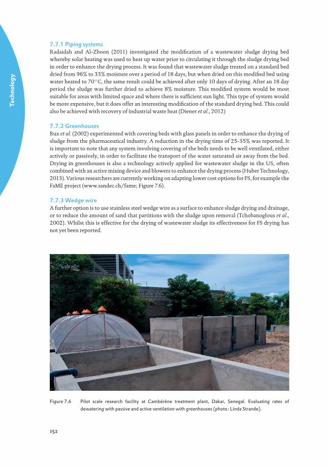
7.7.2 GreenhousesBux et al. (2002) experimented with covering beds with glass panels in order to enhance the drying of sludge from the pharmaceutical industry. A reduction in the drying time of 25-35% was reported. It is important to note that any system involving covering of the beds needs to be well ventilated, either actively or passively, in order to facilitate the transport of the water saturated air away from the bed. Drying in greenhouses is also a technology actively applied for wastewater sludge in the US, often combined with an active mixing device and blowers to enhance the drying process (Huber Technology, 2013). Various researchers are currently working on adapting lower cost options for FS, for example the FaME project (www.sandec.ch/fame; Figure 7.6).
7.7.3 Wedge wireA further option is to use stainless steel wedge wire as a surface to enhance sludge drying and drainage, or to reduce the amount of sand that partitions with the sludge upon removal (Tchobanoglous et al., 2002). Whilst this is effective for the drying of wastewater sludge its effectiveness for FS drying has not yet been reported.
Figure 7.6 Pilot scale research facility at Cambérène treatment plant, Dakar, Senegal. Evaluating rates of
dewatering with passive and active ventilation with greenhouses (photo: Linda Strande).
Tech
nolo
gy
153
7.7.4 Additives to the sludge to enhance dryingPescod (1971) makes reference to a study conducted by Luong in Bangkok, Thailand where alum (potassium aluminium sulphate) was added to the FS in order to increase the rate of drying. This study found that conditioning with alum should only be carried out during the wet season, as there was no signifi cant advantage in conditioning the sludge during the dry season. Research on coagulants for FS treatment is also being conducted as part of the FaME project.
7.8 CONCLUSIONS
Based on the information provided in this chapter, it can be concluded that while some knowledge on the use of unplanted sludge drying beds for FS treatment exists, more detailed research is required in order to provide clear guidelines on their design and operation, and to assist in understanding and overcoming problems.
7.9 REFERENCES
Badji, K., 2008. Traitement des boues de vidange : éléments affectant la performance des lits de séchage non plantés en
taille réelle et les mécanismes de séchage (Faecal sludge treatment: parameters affecting the unplanted drying
beds effi ciency and drying mechanism at real scale). Engineer degree, Génie des Procédés, Ecole Supérieure
Polytechnique, Dakar, Senegal.
Badji K., Dodane P.H., Mbéguéré, M., Kone D., (2011), Traitement des boues de vidange : éléments affectant la
performance des lits de séchage non plantés en taille réelle et les mécanismes de séchage. Actes du symposium
international sur la Gestion des Boues de Vidange, Dakar, 30 juin – 1er juillet 2009, EAWAG/SANDEC.
Bux, M., Baumann, R., Quadt, S., Pinnekamp, J., Mühlbauer, W. (2002). Volume reduction and biological stabilization
of sludge in small sewage plants by solar drying. Drying Technology 20 (4-5), p. 829-837.
Cofi e, O., Agbottah, S., Strauss, M., Esseku, H., Montangero, A. (2006). Solid- liquid separation of faecal sludge using
drying beds in Ghana: implications for nutrient recycling in urban agriculture. Water Research 40(1), p. 75-82.
Cofi e, O., Koné, D. (2009). Case study of sustainable sanitation projects: Co-composting of faecal sludge & organic
solid waste. Kumasi, Ghana. Available from www.susana.org. Accessed September 2013.
Diener, S., Reiser, J.C., Murray, A., Mbéguéré, M., Strande, L. (2012). Recovery of industrial waste heat for faecal sludge
drying. SANDEC News no. 13, p.16.
Duchène, P. (1990). Les systèmes de traitement des boues des stations d’épuration des petites collectivités.
Documentation technique FNDAE 09, Ministère de l’Agriculture et de la Forêt, France, in French. Available
from www.fndae.fr/archive/PDF/fndae09-a.pdf.
HPCIDBC (2011). Status and Strategy for Faecal Sludge Management in the Kathmandu Valley, High Powered
Committee for Integrated Development of the Bagmati Civilization, Kathmandu, Nepal.
Heinss U., Larmie S.A., Strauss, M. (1998). Solids Separation and Pond Systems for the Treatment of Faecal Sludges in
the Tropics. SANDEC Report No.5/98 Second Edition, EAWAG/SANDEC, Duebendorf Switzerland.
Huber Technology (2013). Huber Solar Active Dryer SRT (PDF). Website www.huber-technology.com, accessed May
21, 2013.
Koné, D., Cofi e, O., Zurbrügg, C., Gallizzi, K., Moser, D., Drescher, S., Strauss, M. (2007). Helminth eggs inactivation
effi ciency by faecal sludge dewatering and co-composting in tropical climates. Water Research 41(19), p.
4397-4402.
Kuffour, A. R., Awuah, E., Anyemedu, F.O.K., Strauss, M., Koné, D., Cofi e, E. (2009). Effect of using different particle
sizes of sand as fi lter media for dewatering faecal sludge. Desalination 248, p. 308-314.
Montangero, A., Strauss, M. (2002). Faecal Sludge Management, SANDEC/EAWAG Lecture Notes.
Pescod, M. B. (1971). Sludge handling and disposal in tropical developing countries. Journal of Water Pollution and
Control Federation 43(4), p. 555-570.
Tech
nolo
gy
154
Radaidah, J. A., Al-Zboon, K. K. (2011). Increase the effi ciency of conventional sand drying beds by using intensive
solar energy: a case study from Jordan. Presented at the 2011 2nd International conference on environmental
science and technology. IPCBEE vol. 6, IACSIT Press, Singapore.
Strauss, M., Montangero, A. (2002). FS Management – Review of Practices, Problems and Initiatives. DFID Engineering
Knowledge and Research Project - R8056. Consultancy report to GHK, the United Kingdom, 73 p.
Tchobanoglous, G., Burton, F.L., Stensel, H.D. (2002). Wastewater Engineering: Treatment and Reuse, 4th edition /
revised. McGraw-Hill Engineering and Computer Science Books.
Tilley, E., Lüthi, C., Morel, A., Zurbrügg, C., Schertenleib, R. (2014). Compendium of Sanitation Systems and
Technologies. Swiss Federal Institute of Aquatic Science and Technology (EAWAG) and WSSCC. Dübendorf,
Switzerland. 2nd revised edition. Available from www. sandec.ch.
End of Chapter Study Questions
1. Describe the main components of unplanted drying beds, and the basic fundamentals of their operation.
2. Name two key mechanisms for the dewatering of sludge with unplanted drying beds uPDBs.
3. List four critical factors that need to be taken into consideration when designing unplanted drying beds.
4. Describe what types of treatment objectives can be met with unplanted drying beds.