chapter 6 counters. overview ripple counter ripple counter synchronous binary counters synchronous...
TRANSCRIPT

CHAPTER 6CHAPTER 6
CountersCounters
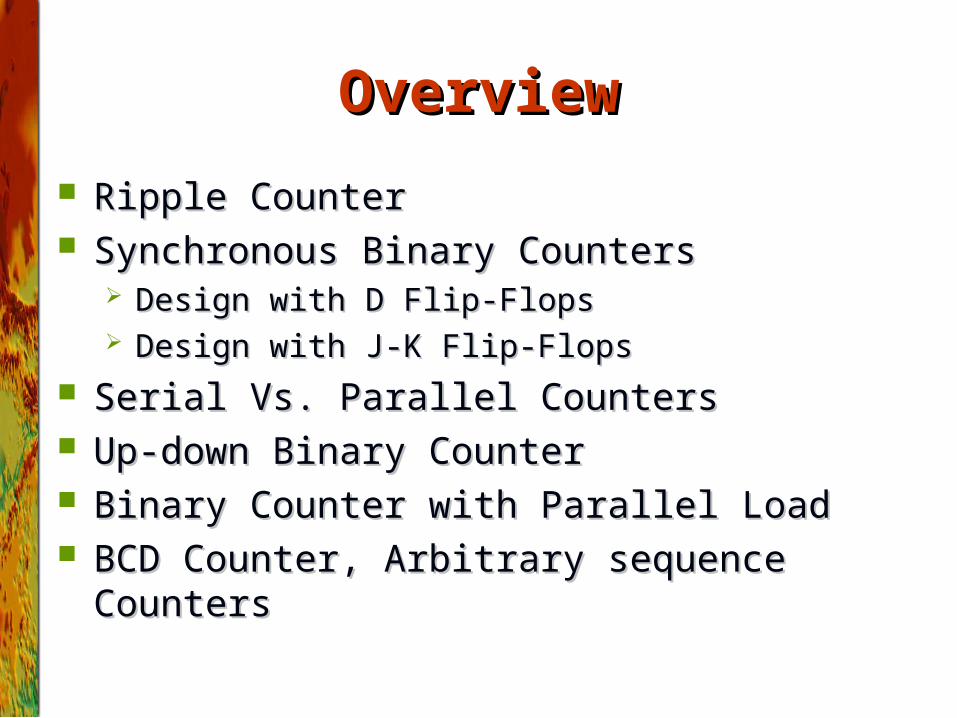
OverviewOverview
Ripple CounterRipple Counter Synchronous Binary CountersSynchronous Binary Counters
Design with D Flip-FlopsDesign with D Flip-Flops Design with J-K Flip-FlopsDesign with J-K Flip-Flops
Serial Vs. Parallel CountersSerial Vs. Parallel Counters Up-down Binary CounterUp-down Binary Counter Binary Counter with Parallel LoadBinary Counter with Parallel Load BCD Counter, Arbitrary sequence CountersBCD Counter, Arbitrary sequence Counters
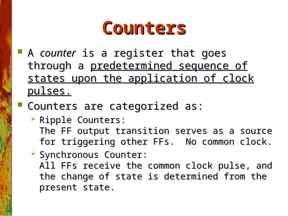
CountersCounters A A countercounter is a register that goes through a is a register that goes through a
predetermined sequence of states upon the application predetermined sequence of states upon the application of clock pulses.of clock pulses.
Counters are categorized as: Counters are categorized as: Ripple Counters: Ripple Counters:
The FF output transition serves as a source for triggering The FF output transition serves as a source for triggering other FFs. No common clock.other FFs. No common clock.
Synchronous Counter:Synchronous Counter:All FFs receive the common clock pulse, and the change of All FFs receive the common clock pulse, and the change of state is determined from the present state.state is determined from the present state.
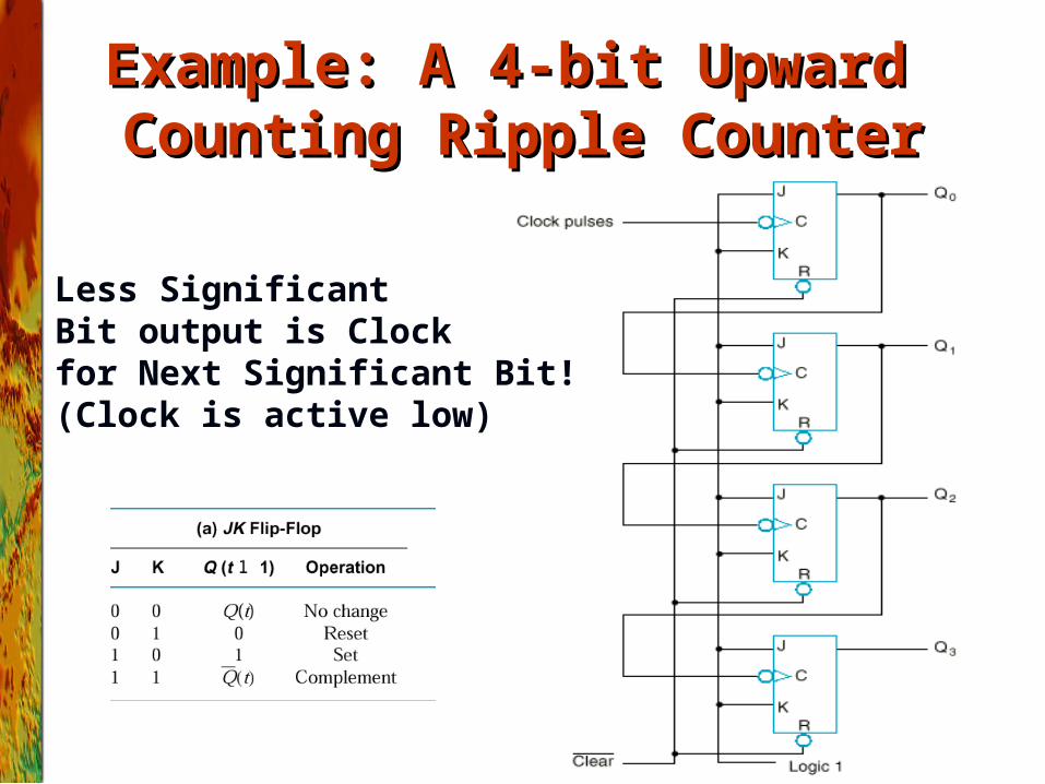
Example: A 4-bit Upward Example: A 4-bit Upward Counting Ripple CounterCounting Ripple Counter
Recall...
Less SignificantBit output is Clockfor Next Significant Bit!(Clock is active low)
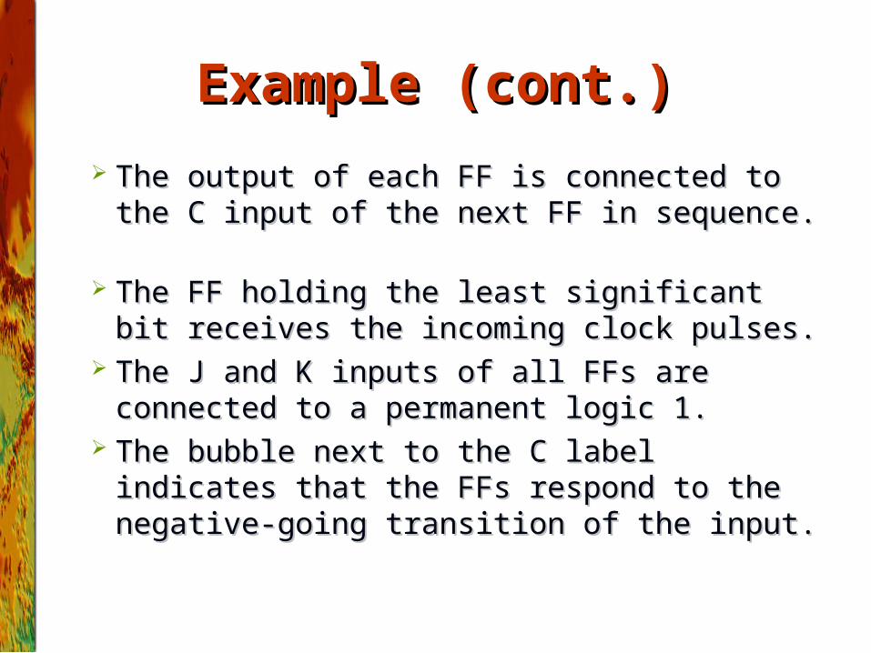
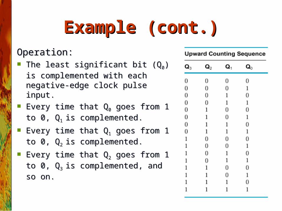
Example (cont.)Example (cont.)
The output of each FF is connected to the C input The output of each FF is connected to the C input of the next FF in sequence. of the next FF in sequence.
The FF holding the least significant bit receives The FF holding the least significant bit receives the incoming clock pulses.the incoming clock pulses.
The J and K inputs of all FFs are connected to a The J and K inputs of all FFs are connected to a permanent logic 1.permanent logic 1.
The bubble next to the C label indicates that the The bubble next to the C label indicates that the FFs respond to the negative-going transition of the FFs respond to the negative-going transition of the input.input.
Example (cont.)Example (cont.)
Operation:Operation: The least significant bit (QThe least significant bit (Q00) is ) is
complemented with each negative-complemented with each negative-edge clock pulse input. edge clock pulse input.
Every time that QEvery time that Q00 goes from 1 to 0, goes from 1 to 0,
QQ1 1 is complemented.is complemented.
Every time that QEvery time that Q11 goes from 1 to 0, goes from 1 to 0,
QQ2 2 is complemented.is complemented.
Every time that QEvery time that Q22 goes from 1 to 0, goes from 1 to 0,
QQ3 3 is complemented, and so on.is complemented, and so on.
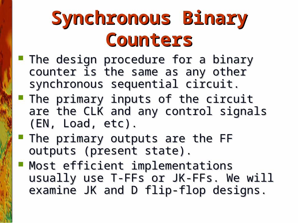
Synchronous Binary CountersSynchronous Binary Counters
The design procedure for a binary counter is the same The design procedure for a binary counter is the same as any other synchronous sequential circuit. as any other synchronous sequential circuit.
The primary inputs of the circuit are the CLK and any The primary inputs of the circuit are the CLK and any control signals (EN, Load, etc).control signals (EN, Load, etc).
The primary outputs are the FF outputs (present The primary outputs are the FF outputs (present state).state).
Most efficient implementations usually use T-FFs or Most efficient implementations usually use T-FFs or JK-FFs. We will examine JK and D flip-flop designs.JK-FFs. We will examine JK and D flip-flop designs.
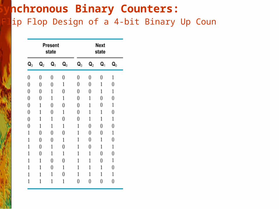
J-K Flip Flop Design of a 4-bit Binary Up Counter Synchronous Binary Counters:
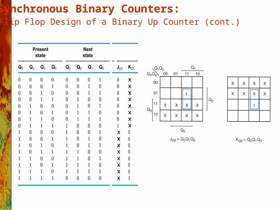
J-K Flip Flop Design of a Binary Up Counter (cont.) Synchronous Binary Counters:
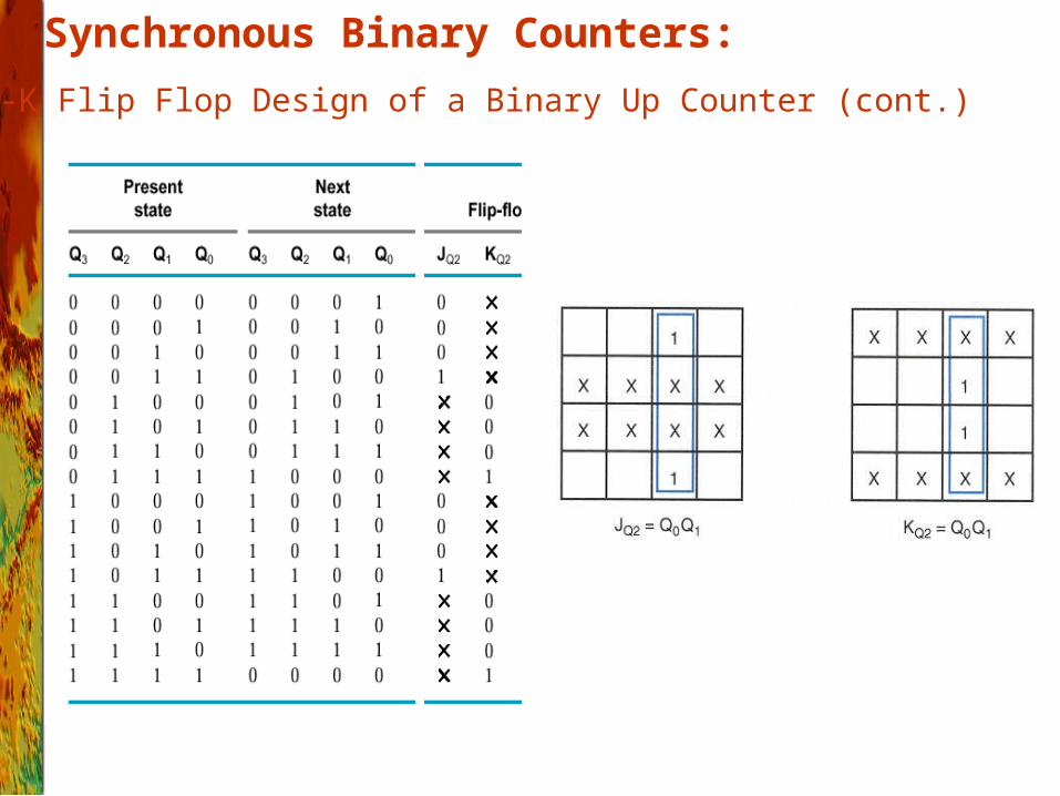
J-K Flip Flop Design of a Binary Up Counter (cont.)
Synchronous Binary Counters:
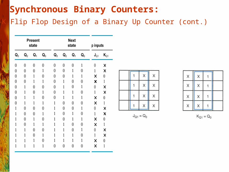
J-K Flip Flop Design of a Binary Up Counter (cont.)
Synchronous Binary Counters:
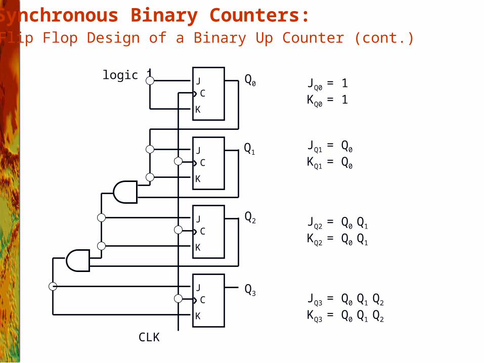
J-K Flip Flop Design of a Binary Up Counter (cont.) Synchronous Binary Counters:
JQ0 = 1KQ0 = 1
JQ1 = Q0
KQ1 = Q0
JQ2 = Q0 Q1
KQ2 = Q0 Q1
JQ3 = Q0 Q1 Q2
KQ3 = Q0 Q1 Q2
J
K
C
J
K
C
J
K
C
J
K
C
CLK
logic 1 Q0
Q1
Q2
Q3
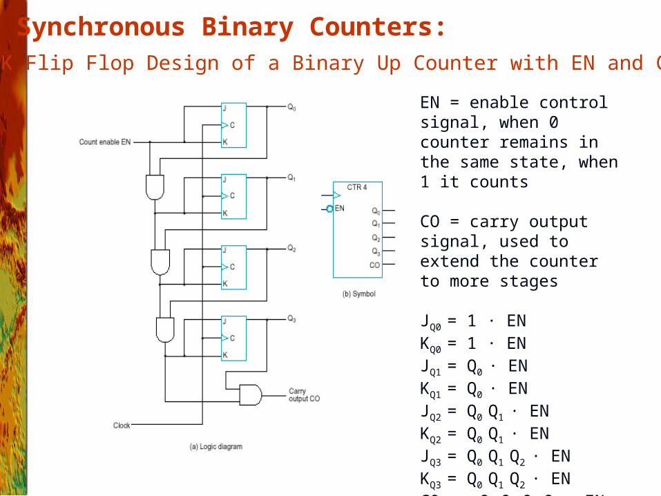
J-K Flip Flop Design of a Binary Up Counter with EN and CO
Synchronous Binary Counters:
EN = enable control signal, when 0 counter remains in the same state, when 1 it counts
CO = carry output signal, used to extend the counter to more stages
JQ0 = 1 · ENKQ0 = 1 · ENJQ1 = Q0 · ENKQ1 = Q0 · ENJQ2 = Q0 Q1 · ENKQ2 = Q0 Q1 · ENJQ3 = Q0 Q1 Q2 · ENKQ3 = Q0 Q1 Q2 · ENC0 = Q0 Q1 Q2 Q3 · EN
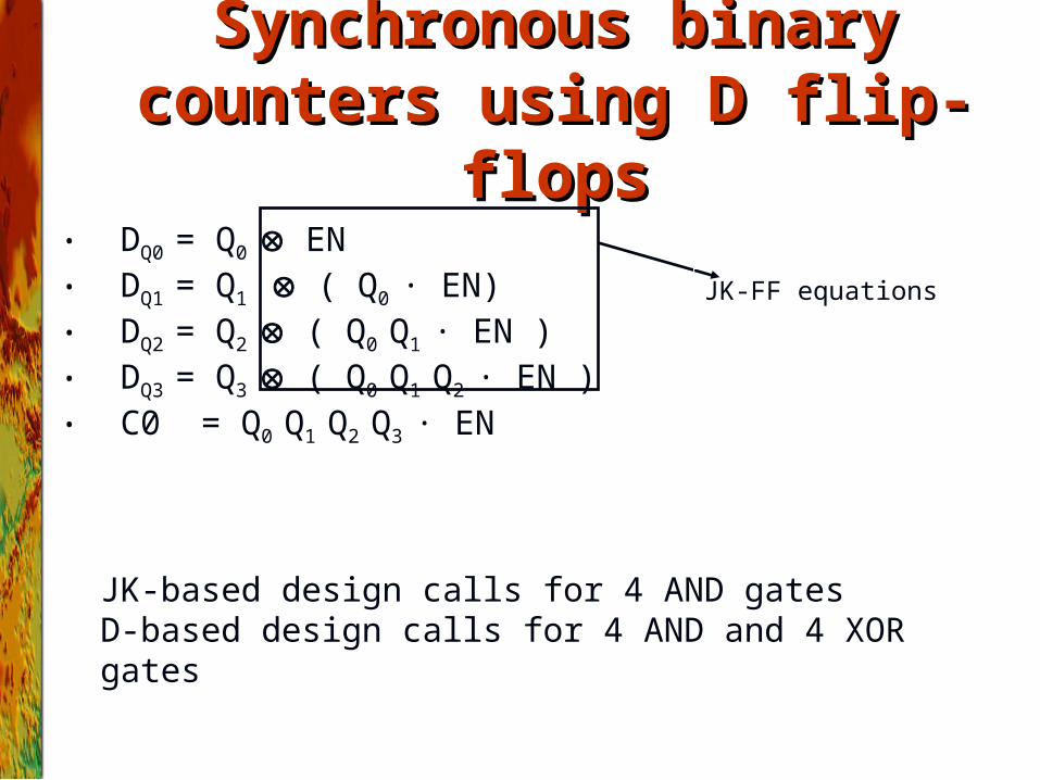
• DQ0 = Q0 EN• DQ1 = Q1 ( Q0 · EN)• DQ2 = Q2 ( Q0 Q1 · EN )• DQ3 = Q3 ( Q0 Q1 Q2 · EN )• C0 = Q0 Q1 Q2 Q3 · EN
JK-based design calls for 4 AND gates D-based design calls for 4 AND and 4 XOR gates
Synchronous binary counters Synchronous binary counters using D flip-flopsusing D flip-flops
JK-FF equations
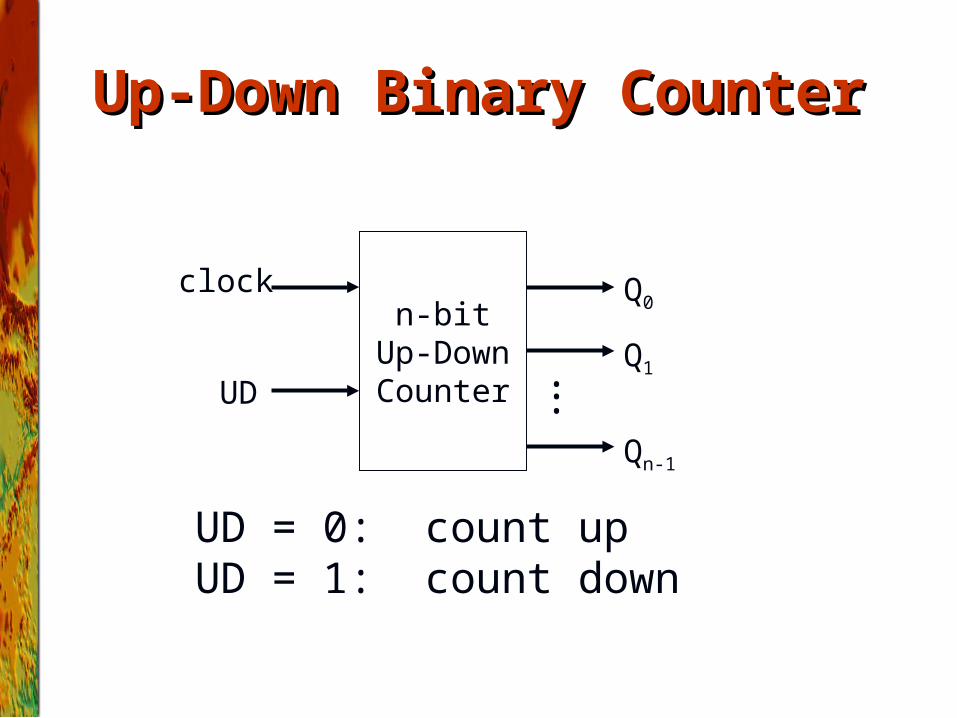
Up-Down Binary CounterUp-Down Binary Counter
n-bitUp-DownCounter
Q0
Q1
Qn-1
clock
UD
UD = 0: count upUD = 1: count down
•••
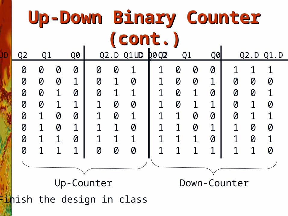
1 0 0 0 1 1 11 0 0 1 0 0 01 0 1 0 0 0 11 0 1 1 0 1 01 1 0 0 0 1 11 1 0 1 1 0 01 1 1 0 1 0 11 1 1 1 1 1 0
UD Q2 Q1 Q0 Q2.D Q1.D Q0.D
0 0 0 0 0 0 10 0 0 1 0 1 00 0 1 0 0 1 10 0 1 1 1 0 00 1 0 0 1 0 10 1 0 1 1 1 00 1 1 0 1 1 10 1 1 1 0 0 0
UD Q2 Q1 Q0 Q2.D Q1.D Q0.D
Up-Counter Down-Counter
Up-Down Binary Counter (cont.)Up-Down Binary Counter (cont.)
Finish the design in class
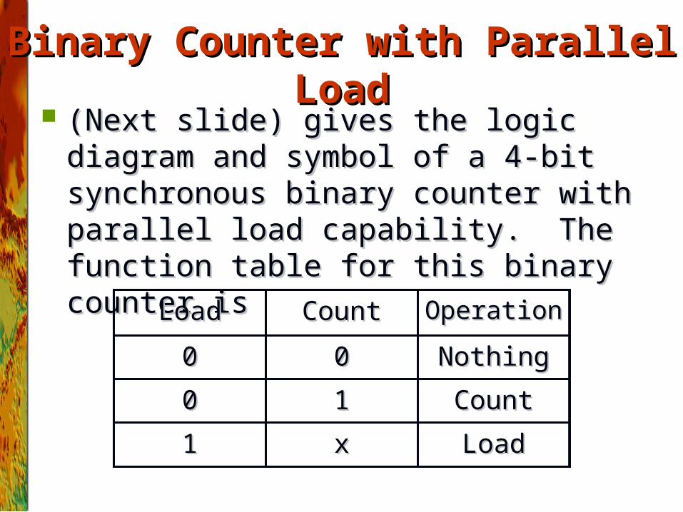
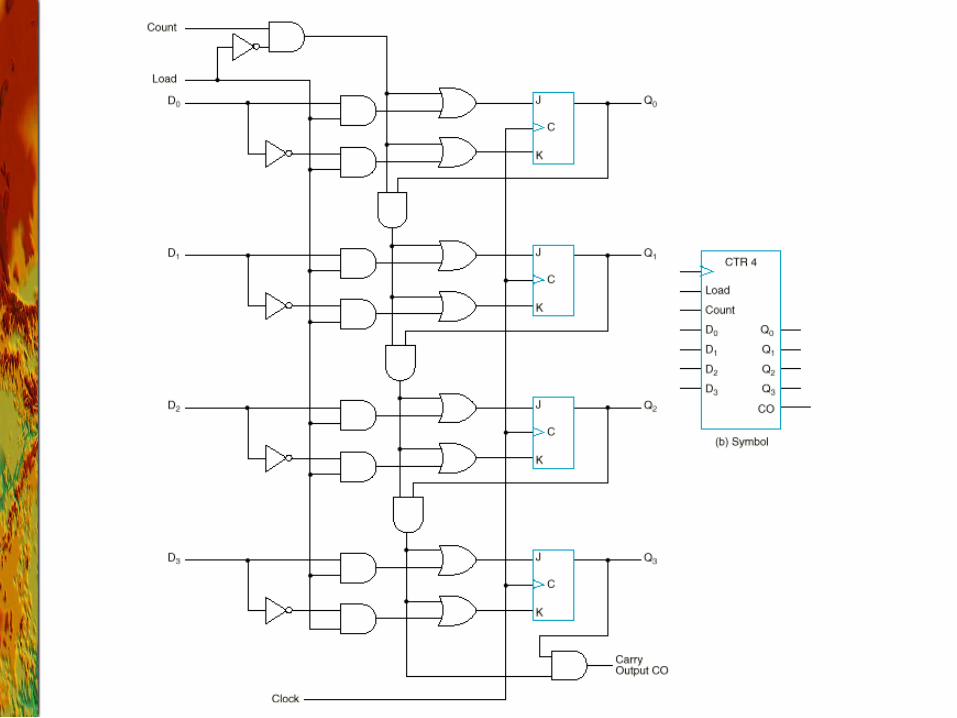
Binary Counter with Parallel LoadBinary Counter with Parallel Load ((Next slide) gives the logic diagram and Next slide) gives the logic diagram and
symbol of a 4-bit synchronous binary counter symbol of a 4-bit synchronous binary counter with parallel load capability. The function with parallel load capability. The function table for this binary counter istable for this binary counter is
LoadLoadxx11
CountCount1100
NothingNothing0000
OperationOperationCountCountLoadLoad
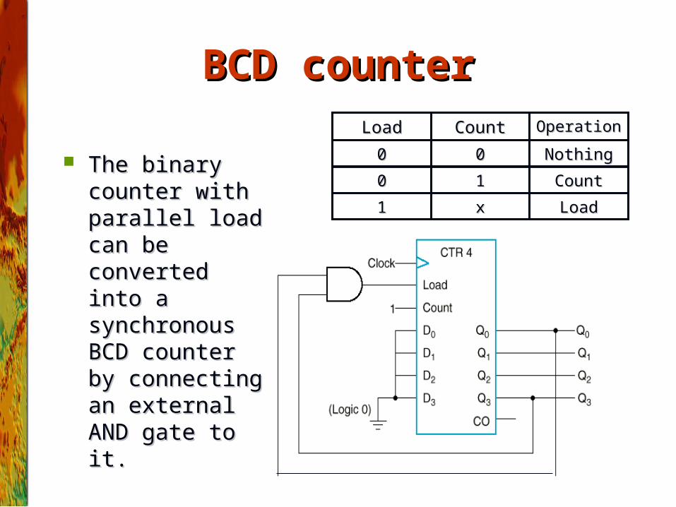
BCD counterBCD counter
The binary counter The binary counter with parallel load with parallel load can be converted can be converted into a synchronous into a synchronous BCD counter by BCD counter by connecting an connecting an external AND gate external AND gate to it.to it.
LoadLoadxx11
CountCount1100
NothingNothing0000
OperationOperationCountCountLoadLoad
BCD counter (cont.)BCD counter (cont.)
The counter starts with an all-zero output.The counter starts with an all-zero output. As long as the output of the AND gate is 0, each positive clock As long as the output of the AND gate is 0, each positive clock
pulse transition increments the counter by one.pulse transition increments the counter by one. When the output reaches the count of When the output reaches the count of 10011001, both Q, both Q00 and Q and Q3 3
become 1, making the output of the AND gate equal to 1. This become 1, making the output of the AND gate equal to 1. This condition makes Load active, so on the next clock transition, condition makes Load active, so on the next clock transition, the counter does not count, but is loaded from its four inputs.the counter does not count, but is loaded from its four inputs.
The value loaded then is 0000.The value loaded then is 0000.
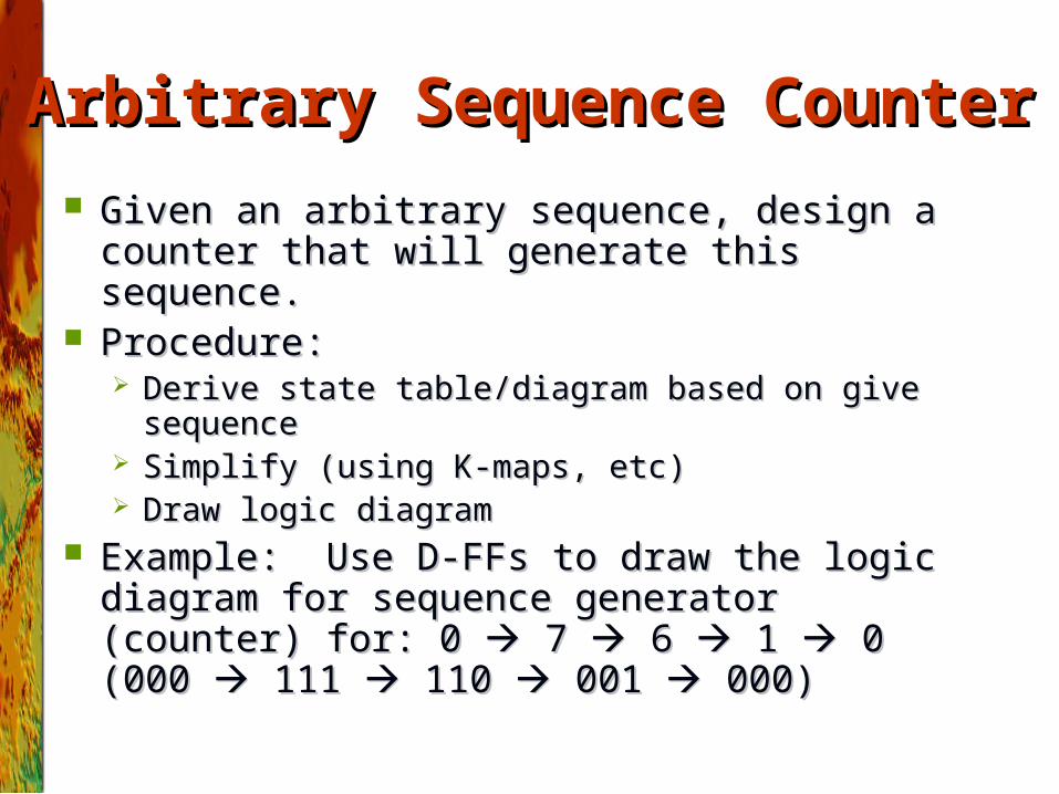
Arbitrary Sequence CounterArbitrary Sequence Counter
Given an arbitrary sequence, design a counter that Given an arbitrary sequence, design a counter that will generate this sequence. will generate this sequence.
Procedure:Procedure: Derive state table/diagram based on give sequenceDerive state table/diagram based on give sequence Simplify (using K-maps, etc)Simplify (using K-maps, etc) Draw logic diagramDraw logic diagram
Example: Use D-FFs to draw the logic diagram for Example: Use D-FFs to draw the logic diagram for sequence generator (counter) for: 0 sequence generator (counter) for: 0 7 7 6 6 1 1 0 (000 0 (000 111 111 110 110 001 001 000) 000)
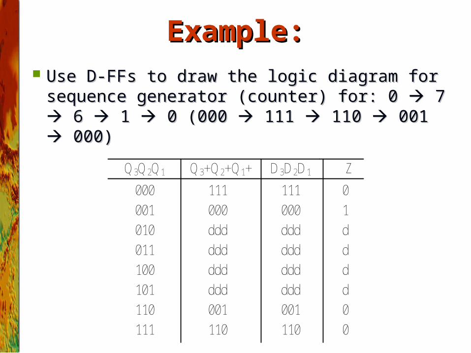
Example:Example:
Use D-FFs to draw the logic diagram for Use D-FFs to draw the logic diagram for sequence generator (counter) for: 0 sequence generator (counter) for: 0 7 7 6 6 1 1 0 (000 0 (000 111 111 110 110 001 001 000) 000)
Q3Q2Q1 Q3+Q2+Q1+ D3D2D1 Z
000
001
ddd
001
110
000
111
111
110
101
100
011
010
001
110
000
111
ddd
ddd
ddd
ddd
ddd
ddd
ddd
d
d
d
d
0
0
1
0
Example:Example:
00 01 11 10
0
1
Q3Q2
Q1
1
1
d
d d
d
00 01 11 10
0
1
Q3Q2
Q1
1
1
d
d d
d
00 01 11 10
0
1
Q3Q2
Q1
1 1d
d d
d
00 01 11 10
0
1
Q3Q2
Q1
1
d
d d
d
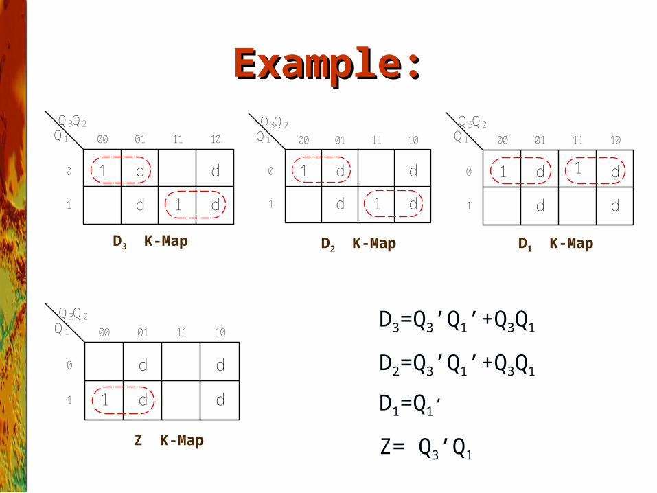
D3 K-Map
Z K-Map
D1 K-MapD2 K-Map
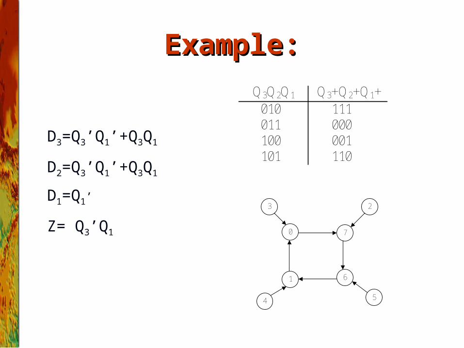
D3=Q3’Q1’+Q3Q1
D2=Q3’Q1’+Q3Q1
D1=Q1’
Z= Q3’Q1
D3=Q3’Q1’+Q3Q1
D2=Q3’Q1’+Q3Q1
D1=Q1’
Z= Q3’Q1
Example:Example:
Q3Q2Q1 Q3+Q2+Q1+010
101100011
111
110001000
0
3 2
1 6
7
4 5
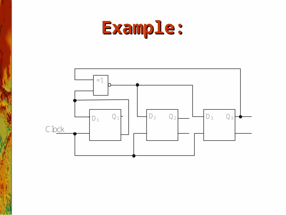
Example:Example:
=1
D1D3D2 Q2Q1 Q3
Clock
HomeworkHomework
Page284: 18Page284: 18