chapter 6 concepts of soil engineering - globalsecurity.org · chapter 6 concepts of soil...
TRANSCRIPT
FM 5-410
CHAPTER 6
C o n c e p t s o f S o i l
E n g i n e e r i n g
The military engineer encounters a widevariety of soils in varying physical states. Be-cause of the inherent variability of thephysical properties of soil, several tests andmeasurements within soils engineering weredeveloped to quantify these differences and toenable the engineer to apply the knowledge toeconomical design and construction. Thischapter deals with soil engineering concepts,to include settlement, shearing resistance,and bearing capacity, and their application inthe military construction arena.
Section I. Settlement
FACTORSThe magnitude of a soil’s settlement
depends on several factors, including—Density.Void ratio.Grain size and shape.Structure.Past loading history of the soil de-posit.Magnitude and method of applicationof the load.Degree of confinement of the soilmass.
Unless otherwise stated, it is assumed thatthe soil mass undergoing settlement is com-pletely confined, generally by the soil thatsurrounds it.
COMPRESSIBILIYCompressibility is the property of a soil that
permits it to deform under the action of an ex-ternal compressive load. Loads discussed inthis chapter are primarily static loads thatact, or may be assumed to act, verticallydownward. Brief mention will be made of theeffects of vibration in causing compression.The principal concern here is with the prop-erty of a soil that permits a reduction inthickness (volume) under a load like that ap-plied by the weight of a highway or airfield.The compressibility of the underlying soilmay lead to the settlement of such a struc-ture.
Compressive Load BehaviorIn a general sense, all soils are compres-
sible. That is, they undergo a greater orlesser reduction in volume under compressivestatic loads. This reduction in volume is at-tributed to a reduction in volume of the voidspaces in the soil rather than to any reductionin size of the individual soil particles or watercontained in the voids.
If the soil is saturated before the load is ap-plied, some water must be forced from thevoids before settlement can take place. Thisprocess is called consolidation. The rate ofconsolidation depends on how quickly thewater can escape, which is a function Of thesoil’s permeability.
Concepts of Soil Engineering 6-1
FM 5-410
Cohesionless SoilsThe compressibility of confined coarse-
grained cohesionless soils, such as sand andgravel, is rarely a practical concern. This isbecause the amount of compression is likelyto be small in a typical case, and any settle-ment will occur rapidly after the load isapplied. Where these soils are located belowthe water table, water must be able to escapefrom the stratum. In the case of coarsematerials existing above the water table andunder less than saturated conditions, the ap-plication of a static load results in therearrangement of soil particles. Thisproduces deformation without regard to mois-ture escape. So, generally speaking,settlement occurs during the period of loadapplication (construction). Deformationsthat are thus produced in sands and gravelsare essentially permanent in character.There is little tendency for the soil to return toits original dimensions or rebound when theload is removed. A sand mass in a compactcondition may eventually attain some degreeof elasticity with repeated applications ofload.
The compressibility of a loose sand depositis much greater than that of the same sand ina relatively dense condition. Generally,structures should not be located on loose sanddeposits. Avoid loose sand deposits if pos-sible, or compact to a greater density beforethe load is applied. Some cohesionless soils,including certain very fine sands and silts,have loose structures with medium settle-ment characteristics. Both gradation andgrain shape influence the compressibility of acohesionless soil. Gradation is of indirect im-portance in that a well-graded soil generallyhas a greater natural density than one ofuniform gradation. Soils that contain platyparticles are more compressible than thosecomposed entirely of bulky grains. A finesand or silt that contains mica flakes maybequite compressible.
Although soils under static loads are em-phasized here, the effects of vibration shouldalso be mentioned. Vibration during con-struction may greatly increase the density of
cohesionless soils. A loose sand deposit sub-jected to vibration after construction may alsochange to a dense condition. The latterchange in density may have disastrous effectson the structures involved. Cohesionlesssoils are usually compacted or “densified” as aplanned part of construction operations.Cohesive soils are usually insensitive to theeffects of vibrations.
CONSOLIDATIONConsolidation is the time-dependent
change in volume of a soil mass under com-pressive load that occurs when water slowlyescapes from the pores or voids of the soil.The soil skeleton is unable to support the loadand changes structure, reducing its volumeand producing vertical settlement.
Cohesive SoilsThe consolidation of cohesive, fine-grained
soils (particularly clays) is quite differentfrom the compression of cohesionless soils.Under comparable static loads, the consolida-tion of a clay may be much greater thancoarse-grained soils and settlement may takea very long time to occur. Structures oftensettle due to consolidation of a saturated claystratum. The consolidation of thick, compres-sible clay layers is serious and may causestructural damage. In uniform settlement,the various parts of a structure settle ap-proximately equal amounts. Such uniformsettlement may not be critical. Nonuniform,or differential, settlement of parts of a struc-ture due to consolidation causes seriousstructural damage. A highway or airfieldpavement may be badly damaged by the non-uniform settlement of an embankmentfounded on a compressible soil.
Consolidation TestsThe consolidation characteristics of a com-
pressible soil should be determined forrational design of many large structuresfounded on or above soils of this type. Con-solidation characteristics generally aredetermined by laboratory consolidation testsperformed on undisturbed samples. Thenatural structure, void ratio, and moisturecontent are preserved as carefully as possiblefor undisturbed samples. However, military
Concepts of Soil Engineering 6-2
FM 5-410
soils analysts are not equipped or trained toperform consolidation tests.
Information on consolidation tests and set-tlement calculations for the design ofstructures to be built on compressible soilsmay be found in Naval Facilities EngineeringCommand Design Manual (NAVFAC DM)-7.1.
Section II. Shearing ResistanceIMPORTANCE
From an engineering viewpoint, one of themost important properties a soil possesses isshearing resistance or shear strength. Asoil’s shearing resistance under given condi-tions is related to its ability to withstandloads. The shearing resistance is especiallyimportant in its relation to the supportingstrength, or bearing capacity, of a soil used asabase or subgrade beneath a road, runway, orother structure. The shearing resistance isalso important in determining the stability ofthe slopes used in a highway or airfield cut orembankment and in estimating the pressuresexerted against an earth-retaining structure,such as a retaining wall.
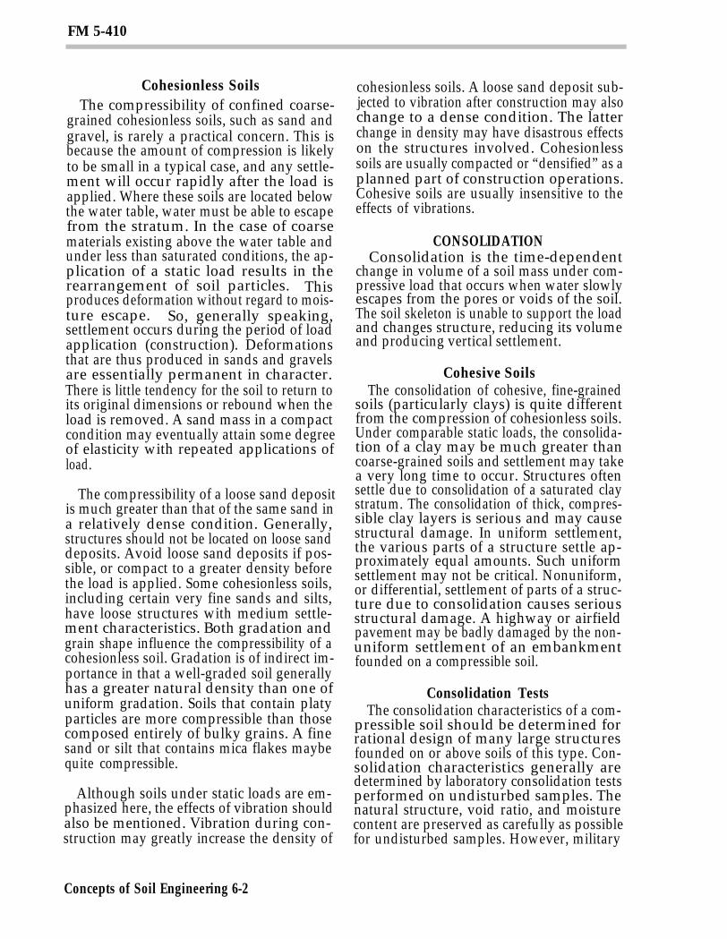
LABORATORY TESTSThree test procedures are commonly used
in soil mechanics laboratories to determinethe shear strength of a soil. These are—
Direct shear test.Triaxial compression test.Unconfined compression test.
The basic principles involved in each ofthese tests are illustrated in the simplifieddrawings of Figure 6-1. Military soilsanalysts are not equipped or trained to per-form the direct shear or triaxial compressiontests. For most military applications, theCBR value of a soil is used as a measure ofshear strength (see TM 5-530).
A variation of the unconfined compressiontest can be performed by military soilsanalysts, but the results are ordinarily usedonly in evaluation of soil stabilization. Shear
strength for a soil is expressed as a combina-tion of an apparent internal angle of friction(normally associated with cohesive soils).
CALIFORNIA BEARING RATIOThe CBR is a measure of the shearing resis-
tance of a soil under carefully controlledconditions of density and moisture. The CBRis determined by a penetration shear test andis used with empirical curves for designingflexible pavements. Recommended designprocedures for flexible pavements are
Concepts of Soil Engineering 6-3
FM 5-410
presented in TM 5-330. The CBR test proce-dure for use in design consists of the followingsteps:
Prepare soil test specimens.Perform penetration test on the pre-pared soil samples.Perform swell test on soil test speci-mens.
Although a standardized procedure hasbeen established for the penetration portionof the test, one standard procedure for thepreparation of test specimens cannot be estab-lished because soil conditions and con-struction methods vary widely. The soil testspecimen is compacted so it duplicates as nearlyas possible the soil conditions in the field.
In a desert environment, soil maybe com-pacted and tested almost completely dry. In awet area, soil should probably be tested at 100percent saturation. Although penetrationtests are most frequently performed onlaboratory-compacted test specimens, theymay also be performed on undisturbed soilsamples or on in-place soil in the field.Detailed procedures for conducting CBR testsand analyzing the data are in TM 5-330.Appendix A describes the procedure for ap-plying CBR test data in designing roads andairfields.
Column 15, Table 5-3, page 5-11, showstypical ranges in value of the field CBR forsoils in the USCS. Values of the field CBRmay range from as low as 3 for highly plastic,inorganic clays (CH) and some organic claysand silts (OH) to as high as 80 for well-gradedgravel and gravel-sand mixtures.
AIRFIELD INDEX (AI)Engineering personnel use the airfield cone
penetrometer to determine an index of soilstrengths (called Airfield Index) for variousmilitary applications.
Airfield Cone PenetrometerThe airfield cone penetrometer is compact,
sturdy, and simple enough to be used bymilitary personnel inexperienced in soil
strength determination. If used correctly, itcan serve as an aid in maintaining field con-trol during construction operations; however,this use is not recommended, because moreaccurate methods are available for use duringconstruction.
Description. The airfield cone pene-trometer is a probe-type instrument consist-ing of a right circular cone with a basediameter of 1/2 inch mounted on a graduatedstaff. On the opposite end of the staff are aspring, a load indicator, and a handle. Theoverall length of the assembled penetrometeris 36 1/8 inches. For ease in carrying, thepenetrometer can be disassembled into threemain pieces. They are—
Two extension staffs, each 12 5/8 in-ches long.One piece 14 3/4 inches long contain-ing the cone, handle, spring, and loadindicator.
The airfield cone penetrometer has a range ofzero to 15.
The airfield cone penetrometer must not beconfused with the trafficability pene-trometer, a standard military item includedin the Soil Test Set. The cone penetrometerused for trafficability has a dial-type loadindicator (zero to 300 range) and is equippedwith a cone 1/2 inch in diameter and across-sectional area of 0.2 square inch andanother cone 0.8 inch in diameter and a cross-sectional area of 0.5 square inch. If thetrafficability penetrometer is used tomeasure the AI, the readings obtained withthe 0.2-square-inch cone must be divided by20; the reading obtained with the 0.5-square-inch cone must be divided by 50.
Operation. Before the penetrometer is used,inspect the instrument to see that all jointsare tight and that the load indicator readszero. To operate the penetrometer, place yourpalms down symmetrically on the handle.Steady your arms against your thighs andapply force to the handle until a slow, steady,downward movement of the instrument oc-curs. Read the load indicator at the moment
Concepts of Soil Engineering 6-4
FM 5-410
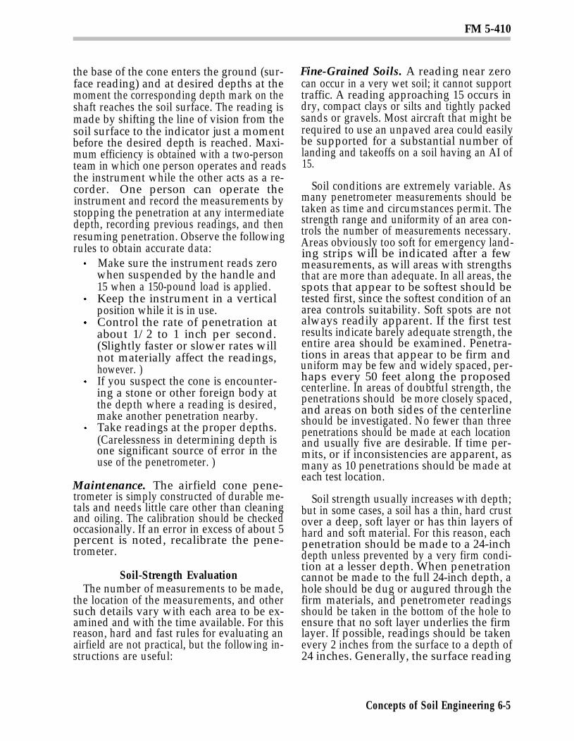
the base of the cone enters the ground (sur-face reading) and at desired depths at themoment the corresponding depth mark on theshaft reaches the soil surface. The reading ismade by shifting the line of vision from thesoil surface to the indicator just a momentbefore the desired depth is reached. Maxi-mum efficiency is obtained with a two-personteam in which one person operates and readsthe instrument while the other acts as a re-corder. One person can operate theinstrument and record the measurements bystopping the penetration at any intermediatedepth, recording previous readings, and thenresuming penetration. Observe the followingrules to obtain accurate data:
Make sure the instrument reads zerowhen suspended by the handle and15 when a 150-pound load is applied.Keep the instrument in a verticalposition while it is in use.Control the rate of penetration atabout 1/2 to 1 inch per second.(Slightly faster or slower rates willnot materially affect the readings,however. )If you suspect the cone is encounter-ing a stone or other foreign body atthe depth where a reading is desired,make another penetration nearby.Take readings at the proper depths.(Carelessness in determining depth isone significant source of error in theuse of the penetrometer. )
Maintenance. The airfield cone pene-trometer is simply constructed of durable me-tals and needs little care other than cleaningand oiling. The calibration should be checkedoccasionally. If an error in excess of about 5percent is noted, recalibrate the pene-trometer.
Soil-Strength EvaluationThe number of measurements to be made,
the location of the measurements, and othersuch details vary with each area to be ex-amined and with the time available. For thisreason, hard and fast rules for evaluating anairfield are not practical, but the following in-structions are useful:
Fine-Grained Soils. A reading near zerocan occur in a very wet soil; it cannot supporttraffic. A reading approaching 15 occurs indry, compact clays or silts and tightly packedsands or gravels. Most aircraft that might berequired to use an unpaved area could easilybe supported for a substantial number oflanding and takeoffs on a soil having an AI of15.
Soil conditions are extremely variable. Asmany penetrometer measurements should betaken as time and circumstances permit. Thestrength range and uniformity of an area con-trols the number of measurements necessary.Areas obviously too soft for emergency land-ing strips will be indicated after a fewmeasurements, as will areas with strengthsthat are more than adequate. In all areas, thespots that appear to be softest should betested first, since the softest condition of anarea controls suitability. Soft spots are notalways readily apparent. If the first testresults indicate barely adequate strength, theentire area should be examined. Penetra-tions in areas that appear to be firm anduniform may be few and widely spaced, per-haps every 50 feet along the proposedcenterline. In areas of doubtful strength, thepenetrations should be more closely spaced,and areas on both sides of the centerlineshould be investigated. No fewer than threepenetrations should be made at each locationand usually five are desirable. If time per-mits, or if inconsistencies are apparent, asmany as 10 penetrations should be made ateach test location.
Soil strength usually increases with depth;but in some cases, a soil has a thin, hard crustover a deep, soft layer or has thin layers ofhard and soft material. For this reason, eachpenetration should be made to a 24-inchdepth unless prevented by a very firm condi-tion at a lesser depth. When penetrationcannot be made to the full 24-inch depth, ahole should be dug or augured through thefirm materials, and penetrometer readingsshould be taken in the bottom of the hole toensure that no soft layer underlies the firmlayer. If possible, readings should be takenevery 2 inches from the surface to a depth of24 inches. Generally, the surface reading
Concepts of Soil Engineering 6-5
FM 5-410
should be disregarded when figures areaveraged to obtain a representative AI.
In the normal soil condition, wherestrength increases with depth, the readingsat the 2- to 8-inch depths (4 to 10 inches fordry sands and for larger aircraft) should beused to designate the soil strength for airfieldevaluation. If readings in this critical layer atany one test location do not differ more than 3or 4 units, the arithmetic average of thesereadings can be taken as the AI for the areasrepresented by the readings. When the rangebetween the highest and lowest readings ismore than about 4, the engineer must usejudgment in arriving at a rating figure. Forconservatism, the engineer should leantoward the low readings.
In an area in which hard crust less thanabout 4 inches thick overlies a much softersoil, the readings in the crust should not beused in evaluating the airfield. For example,if a 3-inch-thick crust shows average readingsof 10 at the 2-inch depth and average read-ings of 5 below 3 inches, the area should beevaluated at 5. If the crust is more than about4 inches thick, it will probably play an impor-tant part in aircraft support. If the crust inthe above instance is 5 inches thick, therating of the field would then be abouthalfway between the 10 of the crust and the 5of the underlying soil or, conservatively, 7.Innumerable combinations of crust thicknessand strength and underlying soil strengthcan occur. Sound reasoning and engineeringjudgment should be used in evaluating suchareas.
In an area in which a very soft, thin layer isunderlain by a firmer layer, the evaluationalso is a matter of judgment. If, for example,there are 1 to 2 inches of soil with an indexaveraging about 5 overlying a soil with anindex of 10, rate the field at 10; but if this softlayer is more than about 4 inches thick, ratethe field at 5. Areas of fine-grained soils withvery low readings in the top 1 inch or more arelikely to be slippery or sticky, especially if thesoil is a clay.
Coarse-Grained Soils. When relativelydry, many sands show increasing AIs with
Concepts of Soil Engineering 6-6
depth, but the 2-inch depth index will often below, perhaps about 3 or 4, Such sands usuallyare capable of supporting aircraft that re-quire a much higher AI than 3 to 4, becausethe strength of the sand actually increasesunder the confining action of the aircrafttires. Generally, any dry sand or gravel isadequate for aircraft in the C-130 class,regardless of the penetrometer readings. Allsands and gravel in a “quick” condition (watermoving upward through them) must heavoided. Evaluation of wet sands should bebased on the penetrometer readings obtainedas described earlier.
Once the strength of the soil, in terms of AI,has been established by use of the airfieldcone penetrometer, the load-carryingcapability of this soil can be determined foreach kind of forward, support, or rear-areaairfield through use of the subgrade strengthrequirements curves. These curves are basedon correlations of aircraft performance andAIs. Unfortunately, these are not exact cor-relations uniquely relating aircraftperformance to AI. As soils vary in type andcondition from site to site, so varies the rela-tion of AI to aircraft performance. For thisreason, the curves may not accurately reflectperformance in all cases. These relationswere selected so that in nearly all casesaircraft performance will be equal to or betterthan that indicated.
CORRELATION BETWEEN CBR AND AlExpedient soil strength measurements in
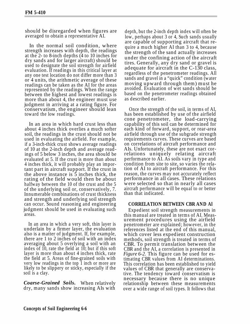
this manual are treated in terms of AI. Meas-urement procedures using the airfieldpenetrometer are explained; however, in thereferences listed at the end of this manual,which cover less expedient constructionmethods, soil strength is treated in terms ofCBR. To permit translation between theCBR and the AI, a correlation is presented inFigure 6-2. This figure can be used for es-timating CBR values from AI determinations.This correlation has been established to yieldvalues of CBR that generally are conserva-tive. The tendency toward conservatism isnecessary because there is no uniquerelationship between these measurementsover a wide range of soil types. It follows that
FM 5-410
the curve should not be used to estimate AIvalues from CBR determinations since thesewould not be conservative.
Section III. Bearing Capacity
IMPORTANCEThe bearing capacity of a soil is its ability to
support loads that may be applied to it by anengineering structure, such as—
A building, a bridge, a highway pave-ment, or an airport runway and themoving loads that may be carriedthereon.An embankment.Other types of load.
A soil with insufficient bearing capacity tosupport the loads applied to it may simply failby shear, allowing the structure to move orsink into the ground. Such a soil may fail be-cause it undergoes excessive deformation,with consequent damage to the structure.Sometimes the ability of a soil to supportloads is simply called its stability. Bearingcapacity is directly related to the allowableload that may be safely placed on a soil. Thisallowable load is sometimes called the allow-able soil pressure.
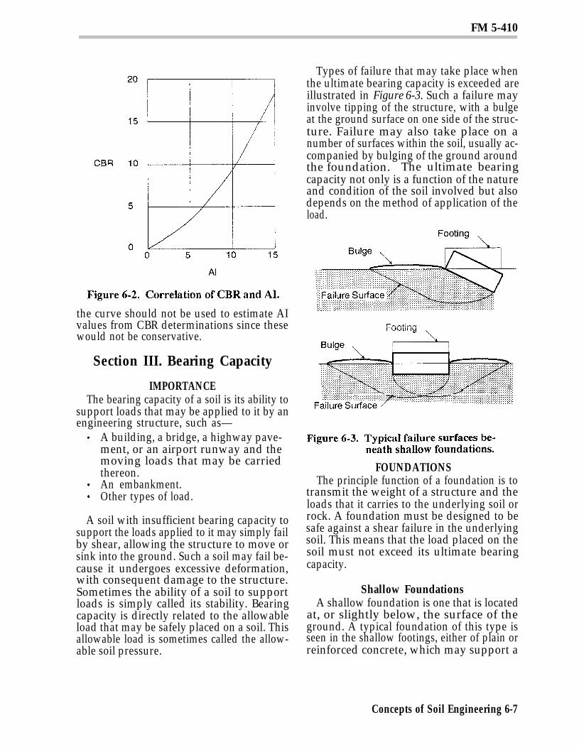
Types of failure that may take place whenthe ultimate bearing capacity is exceeded areillustrated in Figure 6-3. Such a failure mayinvolve tipping of the structure, with a bulgeat the ground surface on one side of the struc-ture. Failure may also take place on anumber of surfaces within the soil, usually ac-companied by bulging of the ground aroundthe foundation. The ultimate bearingcapacity not only is a function of the natureand condition of the soil involved but alsodepends on the method of application of theload.
FOUNDATIONSThe principle function of a foundation is to
transmit the weight of a structure and theloads that it carries to the underlying soil orrock. A foundation must be designed to besafe against a shear failure in the underlyingsoil. This means that the load placed on thesoil must not exceed its ultimate bearingcapacity.
Shallow FoundationsA shallow foundation is one that is located
at, or slightly below, the surface of theground. A typical foundation of this type isseen in the shallow footings, either of plain orreinforced concrete, which may support a
Concepts of Soil Engineering 6-7
FM 5-410
building. Footings are generally square orrectangular. Long continuous or strip foot-ings are also used, particularly beneathbasement or retaining walls. Another type ofshallow foundation is the raft or mat; it maycover a large area, perhaps the entire area oc-cupied by a structure.
Deep FoundationsWhen the surface soils at the site of a
proposed structure are too weak and com-pressible to provide adequate support, deepfoundations are frequently used to transferthe load to underlying suitable soils. Twocommon types of deep foundations are—
Pile.Pier.
Piles. Piles and pile foundations are verycommonly used in both military and civil con-struction. By common usage, a pile is aload-bearing member made of timber, con-crete, or steel, which is generally forced intothe ground. Piles are used in a variety offorms and for a variety of purposes. A pilefoundation is one or more piles used to sup-port a pier, or column, or a row of piles undera wall. Piles of this type are normally used tosupport vertical loads, although they mayalso be used to support inclined or lateral for-ces.
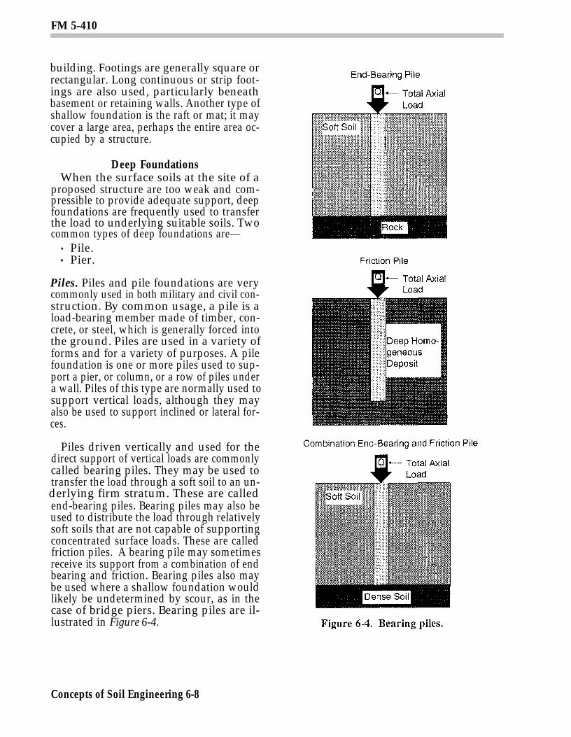
Piles driven vertically and used for thedirect support of vertical loads are commonlycalled bearing piles. They may be used totransfer the load through a soft soil to an un-derlying firm stratum. These are calledend-bearing piles. Bearing piles may also beused to distribute the load through relativelysoft soils that are not capable of supportingconcentrated surface loads. These are calledfriction piles. A bearing pile may sometimesreceive its support from a combination of endbearing and friction. Bearing piles also maybe used where a shallow foundation wouldlikely be undetermined by scour, as in thecase of bridge piers. Bearing piles are il-lustrated in Figure 6-4.
Concepts of Soil Engineering 6-8
FM 5-410
A typical illustration of an end-bearing pileis when a pile driven through a very soft soil,such as a loose silt or the mud of a river bot-tom, comes to rest on firm stratum beneath.The firm stratum may, for example, be rock,sand, or gravel. In such cases, the pile derivespractically all its support from the underlyingfirm stratum.
A friction pile develops its load-carryingcapacity entirely, or principally, from skinfriction along the sides of the pile. The load istransferred to the adjoining soil by friction be-tween the pile and the surrounding soil. Theload is thus transferred downward andlaterally to the soil. The soil surrounding thepile or group of piles, as well as that beneaththe points of the piles, is stressed by the load.
Some piles carry a load by a combination offriction and end bearing. A pile of this sortmay pass through a fairly soft soil thatprovides some frictional resistance; then itmay pass into a firm layer that develops load-carrying capacity through a combination offriction over a relatively short length of em-bedment and end bearing.
Piles are used for many purposes otherthan support for vertical loads. Piles that aredriven at an angle with the vertical are com-monly called batter piles. They may be usedto support inclined loads or to provide lateralloads. Piles are sometimes used to supportlateral loads directly, as in the pile fendersthat may be provided along waterfront struc-tures to take the wear and shock of dockingships. Sometimes piles are used to resist up-ward, tensile forces. These are frequentlycalled anchor piles. Anchor piles may beused, for example, as anchors for bulkheads,retaining walls, or guy wires. Vertical pilesare sometimes driven for the purpose of com-pacting loose cohesionless deposits. Closelyspaced piles, or sheet piles, may be driven toform a wall or a bulkhead that restrains a soilmass.
Piers. Piers are much less common thanpiles and are normally used only for the sup-port of very heavy loads.
Section IV. Earth-RetainingStructures
PURPOSEEarth-retaining structures must be used to
restrain a mass of earth that will not standunsupported. Such structures are commonlyrequired when a cut is made or when an em-bankment is formed with slopes too steep tostand alone.
Earth-retaining structures are subjected tolateral thrust from the earth masses thatthey support. The pressure of the earth onsuch a structure is commonly called lateralearth pressure. The lateral earth pressurethat may be exerted by a given soil on a givenstructure is a function of many variables. Itmust be estimated with a reasonable degreeof accuracy before an earth-retaining struc-ture may be properly designed. In manycases, the lateral earth pressure may be as-sumed to be acting in a horizontal directionor nearly so.
TYPESEarth-retaining structures discussed in
this section are retaining walls and bracingsystems used in temporary excavations.
Retaining WallsA retaining wall is a wall constructed to
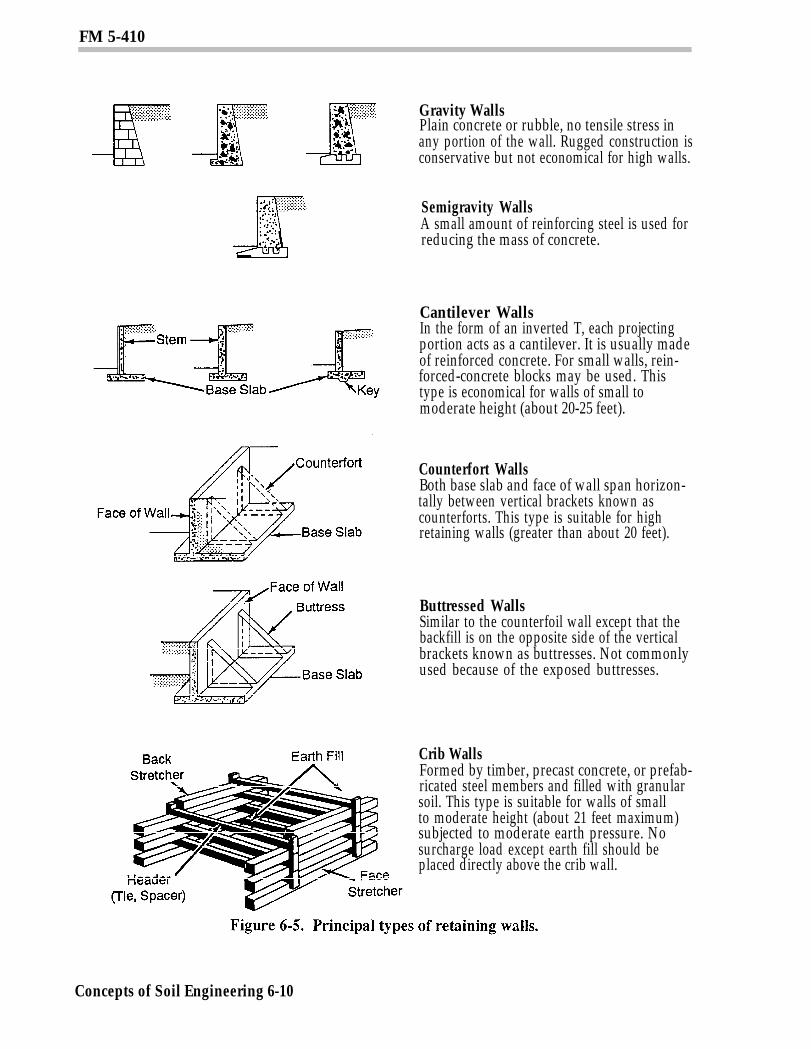
support a vertical or nearly vertical earthbank that, in turn, may support verticalloads. Generally, retaining walls are clas-sified into the following five types (see Figure6-5, page 6-10):
Gravity.Cantilever.Counterfort.Buttressed.Crib.
When a retaining wall is used to supportthe end of a bridge span, as well as retain theearth backfill, it is called an abutment. Thereare several types of gravity retaining walls,such as—
Timber.Plain concrete.
Concepts of Soil Engineering 6-9
FM 5-410
Gravity WallsPlain concrete or rubble, no tensile stress inany portion of the wall. Rugged construction isconservative but not economical for high walls.
Semigravity WallsA small amount of reinforcing steel is used forreducing the mass of concrete.
..7
Cantilever WallsIn the form of an inverted T, each projectingportion acts as a cantilever. It is usually madeof reinforced concrete. For small walls, rein-forced-concrete blocks may be used. Thistype is economical for walls of small tomoderate height (about 20-25 feet).
Counterfort WallsBoth base slab and face of wall span horizon-tally between vertical brackets known ascounterforts. This type is suitable for highretaining walls (greater than about 20 feet).
Buttressed WallsSimilar to the counterfoil wall except that thebackfill is on the opposite side of the verticalbrackets known as buttresses. Not commonlyused because of the exposed buttresses.
Crib WallsFormed by timber, precast concrete, or prefab-ricated steel members and filled with granularsoil. This type is suitable for walls of smallto moderate height (about 21 feet maximum)subjected to moderate earth pressure. Nosurcharge load except earth fill should beplaced directly above the crib wall.
Concepts of Soil Engineering 6-10
FM 5-410
Sheet piling.Rubble.Stone or brick masonry.Crib.Gabions.
Retaining walls are used in many applica-tions. For example, a structure of this sortmay be used in a highway or railroad cut topermit the use of a steep slope and avoid ex-cessive amounts of excavation. Retainingwalls are similarly used on the embankmentside of sidehill sections to avoid excessivevolumes of fill. Bridge abutments and theheadwalls of culverts frequently function asretaining walls. In the construction of build-ings and various industrial structures,retaining walls are often used to provide sup-port for the side of deep, permanentexcavations.
Permanent retaining walls are generallyconstructed from plain or reinforced concrete;stone masonry walls are also used occasion-ally. In military construction, timber cribretaining walls are important. Their designis discussed later.
Backfills. The design of the backfill for aretaining wall is as important as the design ofthe wall itself. The backfill must be materialsthat are—
Reasonably clean.Granular.Essentially cohesionless.Easily drained.Not susceptible to frost action.
The best materials for backfills behindretaining walls are clean sands, gravels, andcrushed rock. In the USCS, the (GW) and(SW) soils are preferred, if they are available.The (GP) and (SP) soils are also satisfactory.These granular materials require compactionto make them stable against the effects ofvibration. Compaction also generally in-creases the angle of internal friction, which isdesirable in that it decreases the lateral pres-sure exerted on the wall. Materials of the(GM), (GC), (SM), and (SC) groups maybeused for backfills behind retaining walls, but
they must be protected against frost actionand may require elaborate drainageprovisions. Fine- grained soils are notdesirable as backfills because they are dif-ficult to drain. If clay soil must be used, thewall should be designed to resist earth pres-sures at rest. Ideal backfill materials arepurely granular soils containing < 5 percentof fines.
Backfills behind retaining walls are com-monly put in place after the structure hasbeen built. The method of compactiondepends on the—
Soil.Equipment available.Working space.
Since most backfills are essentiallycohesionless, they are best compacted byvibration. Equipment suitable for use withthese soils is discussed in Chapter 8. Com-mon practice calls for the backfill to be placedin layers of loose material that, when com-pacted, results in a compacted layer thicknessof from 6 to 8 inches. Each layer is compactedto a satisfactory density. In areas inacces-sible to rollers or similar compactingequipment, compaction may be done by theuse of mechanical air tampers or hand tools.
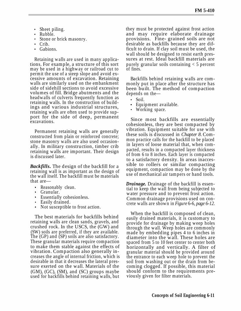
Drainage. Drainage of the backfill is essen-tial to keep the wall from being subjected towater pressure and to prevent frost action.Common drainage provisions used on con-crete walls are shown in Figure 6-6, page 6-12.
When the backfill is composed of clean,easily drained materials, it is customary toprovide for drainage by making weep holesthrough the wall. Weep holes are commonlymade by embedding pipes 4 to 6 inches indiameter into the wall. These holes arespaced from 5 to 10 feet center to center bothhorizontally and vertically. A filter ofgranular material should be provided aroundthe entrance to each weep hole to prevent thesoil from washing out or the drain from be-coming clogged. If possible, this materialshould conform to the requirements pre-viously given for filter materials.
Concepts of Soil Engineering 6-11
FM 5-410
Weep holes have the disadvantage of dis-charging the water that seeps through thebackfill at the toe of the wall where the soilpressures are greatest. The water mayweaken the soil at this point and cause thewall to fail. A more effective solution, whichis also more expensive, is to provide a lon-gitudinal back drain along the base of the wall(see Figure 6-6). A regular pipe drain should
be used, surrounded with a suitable filtermaterial. The drainage may be dischargedaway from the ends of the wall.
If a granular soil, which contains consider-able fine material and is poorly drained (suchas an (SC) soil) is used in the backfill, thenmore elaborate provisions may be installedto ensure drainage. One such approach is touse a drainage blanket (see Figure 6-6). If
Concepts of Soil Engineering 6-12
FM 5-410
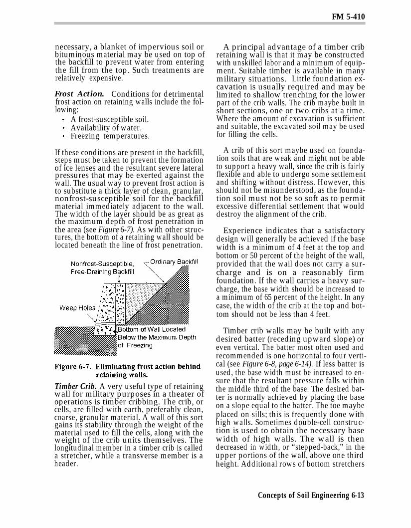
necessary, a blanket of impervious soil orbituminous material may be used on top ofthe backfill to prevent water from enteringthe fill from the top. Such treatments arerelatively expensive.
Frost Action. Conditions for detrimentalfrost action on retaining walls include the fol-lowing:
A frost-susceptible soil.Availability of water.Freezing temperatures.
If these conditions are present in the backfill,steps must be taken to prevent the formationof ice lenses and the resultant severe lateralpressures that may be exerted against thewall. The usual way to prevent frost action isto substitute a thick layer of clean, granular,nonfrost-susceptible soil for the backfillmaterial immediately adjacent to the wall.The width of the layer should be as great asthe maximum depth of frost penetration inthe area (see Figure 6-7). As with other struc-tures, the bottom of a retaining wall should belocated beneath the line of frost penetration.
Timber Crib. A very useful type of retainingwall for military purposes in a theater ofoperations is timber cribbing. The crib, orcells, are filled with earth, preferably clean,coarse, granular material. A wall of this sortgains its stability through the weight of thematerial used to fill the cells, along with theweight of the crib units themselves. Thelongitudinal member in a timber crib is calleda stretcher, while a transverse member is aheader.
A principal advantage of a timber cribretaining wall is that it may be constructedwith unskilled labor and a minimum of equip-ment. Suitable timber is available in manymilitary situations. Little foundation ex-cavation is usually required and may belimited to shallow trenching for the lowerpart of the crib walls. The crib maybe built inshort sections, one or two cribs at a time.Where the amount of excavation is sufficientand suitable, the excavated soil may be usedfor filling the cells.
A crib of this sort maybe used on founda-tion soils that are weak and might not be ableto support a heavy wall, since the crib is fairlyflexible and able to undergo some settlementand shifting without distress. However, thisshould not be misunderstood, as the founda-tion soil must not be so soft as to permitexcessive differential settlement that woulddestroy the alignment of the crib.
Experience indicates that a satisfactorydesign will generally be achieved if the basewidth is a minimum of 4 feet at the top andbottom or 50 percent of the height of the wall,provided that the wail does not carry a sur-charge and is on a reasonably firmfoundation. If the wall carries a heavy sur-charge, the base width should be increased toa minimum of 65 percent of the height. In anycase, the width of the crib at the top and bot-tom should not be less than 4 feet.
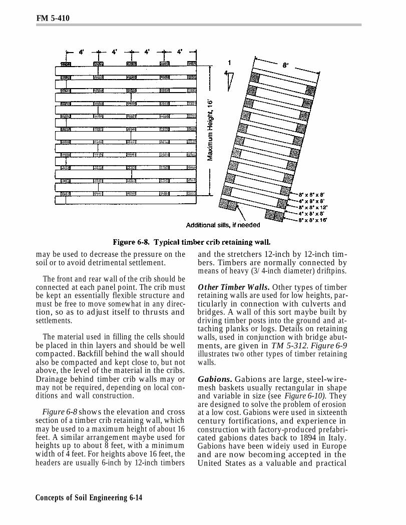
Timber crib walls may be built with anydesired batter (receding upward slope) oreven vertical. The batter most often used andrecommended is one horizontal to four verti-cal (see Figure 6-8, page 6-14). If less batter isused, the base width must be increased to en-sure that the resultant pressure falls withinthe middle third of the base. The desired bat-ter is normally achieved by placing the baseon a slope equal to the batter. The toe maybeplaced on sills; this is frequently done withhigh walls. Sometimes double-cell construc-tion is used to obtain the necessary basewidth of high walls. The wall is thendecreased in width, or “stepped-back,” in theupper portions of the wall, above one thirdheight. Additional rows of bottom stretchers
Concepts of Soil Engineering 6-13
FM 5-410
may be used to decrease the pressure on thesoil or to avoid detrimental settlement.
The front and rear wall of the crib should beconnected at each panel point. The crib mustbe kept an essentially flexible structure andmust be free to move somewhat in any direc-tion, so as to adjust itself to thrusts andsettlements.
The material used in filling the cells shouldbe placed in thin layers and should be wellcompacted. Backfill behind the wall shouldalso be compacted and kept close to, but notabove, the level of the material in the cribs.Drainage behind timber crib walls may ormay not be required, depending on local con-ditions and wall construction.
Figure 6-8 shows the elevation and crosssection of a timber crib retaining wall, whichmay be used to a maximum height of about 16feet. A similar arrangement maybe used forheights up to about 8 feet, with a minimumwidth of 4 feet. For heights above 16 feet, theheaders are usually 6-inch by 12-inch timbers
and the stretchers 12-inch by 12-inch tim-bers. Timbers are normally connected bymeans of heavy (3/4-inch diameter) driftpins.
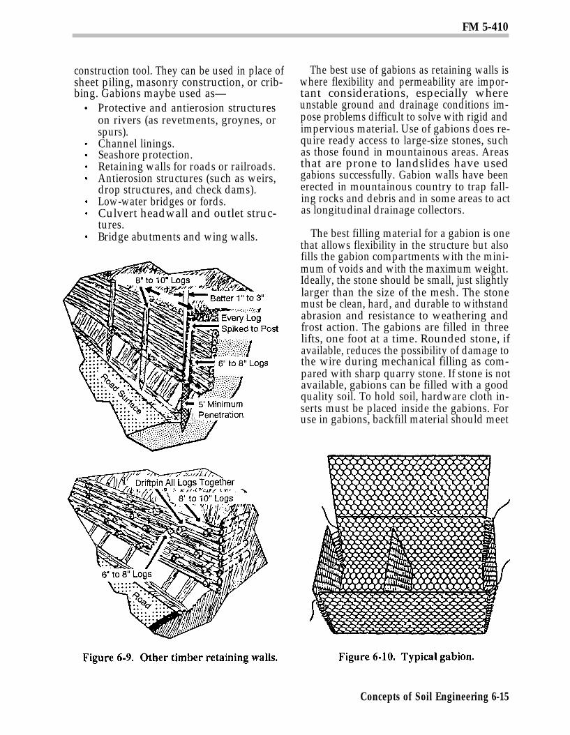
Other Timber Walls. Other types of timberretaining walls are used for low heights, par-ticularly in connection with culverts andbridges. A wall of this sort maybe built bydriving timber posts into the ground and at-taching planks or logs. Details on retainingwalls, used in conjunction with bridge abut-ments, are given in TM 5-312. Figure 6-9illustrates two other types of timber retainingwalls.
Gabions. Gabions are large, steel-wire-mesh baskets usually rectangular in shapeand variable in size (see Figure 6-10). Theyare designed to solve the problem of erosionat a low cost. Gabions were used in sixteenthcentury fortifications, and experience inconstruction with factory-produced prefabri-cated gabions dates back to 1894 in Italy.Gabions have been wideiy used in Europeand are now becoming accepted in theUnited States as a valuable and practical
Concepts of Soil Engineering 6-14
FM 5-410
construction tool. They can be used in place ofsheet piling, masonry construction, or crib-bing. Gabions maybe used as—
Protective and antierosion structureson rivers (as revetments, groynes, orspurs).Channel linings.Seashore protection.Retaining walls for roads or railroads.Antierosion structures (such as weirs,drop structures, and check dams).Low-water bridges or fords.Culvert headwall and outlet struc-tures.Bridge abutments and wing walls.
The best use of gabions as retaining walls iswhere flexibility and permeability are impor-tant considerations, especially whereunstable ground and drainage conditions im-pose problems difficult to solve with rigid andimpervious material. Use of gabions does re-quire ready access to large-size stones, suchas those found in mountainous areas. Areasthat are prone to landslides have usedgabions successfully. Gabion walls have beenerected in mountainous country to trap fall-ing rocks and debris and in some areas to actas longitudinal drainage collectors.
The best filling material for a gabion is onethat allows flexibility in the structure but alsofills the gabion compartments with the mini-mum of voids and with the maximum weight.Ideally, the stone should be small, just slightlylarger than the size of the mesh. The stonemust be clean, hard, and durable to withstandabrasion and resistance to weathering andfrost action. The gabions are filled in threelifts, one foot at a time. Rounded stone, ifavailable, reduces the possibility of damage tothe wire during mechanical filling as com-pared with sharp quarry stone. If stone is notavailable, gabions can be filled with a goodquality soil. To hold soil, hardware cloth in-serts must be placed inside the gabions. Foruse in gabions, backfill material should meet
Concepts of Soil Engineering 6-15
FM 5-410
the following Federal Highway Administrat-ion criteria:
For a 6-inch sieve, 100 percent of thematerial should pass through.For a 3-inch sieve, 75 to 100 percentof the material should pass through.For a Number 200 sieve, zero to 25percent of the material should passthrough.The PI should be 6 or less.
Excavation Bracing SystemsBracing systems maybe required to protect
the sides of temporary excavations duringconstruction operations. Such temporary ex-cavations may be required for severalpurposes but are most often needed in connec-tion with the construction of foundations forstructures and the placing of utility lines,such as sewer and water pipes.
Shallow Excavations. The term “shallowexcavation” refers to excavations made todepths of 12 to 20 feet below the surface,depending principally on the soil involved.The lower limit applies to fairly soft clay soils,while the upper limit generally applies tosands and sandy soils.
Shallow excavations may be made as opencuts with unsupported slopes, particularlywhen the excavation is being done above thewater table, Chapter 10 gives recommendat-ions previously given relative to safe slopesin cuts that are applicable here if the excava-tion is to remain open for any length of time.If the excavation is purely temporary in na-ture, most sandy soils above the water tablewill stand at somewhat steeper slopes (asmuch as 1/2 to 1 for brief periods), althoughsome small slides may take place. Clays maybe excavated to shallow depths with verticalslopes and will remain stable briefly.Generally, bracing cuts in clay that extend todepths of 5 feet or more below the surface aresafer unless flat slopes are used.
Even for relatively shallow excavations,using unsupported cuts may be unsatisfac-tory for several reasons. Cohesive soils may
stand on steep slopes temporarily, but brac-ing is frequently needed to protect against asudden cave-in. Required side slopes, par-ticularly in loose, granular soils, may be soflat as to require an excessive amount of ex-cavation. If the excavation is being done closeto other structures, space maybe limited, orthe consequences of the failure of a side slopemay be very serious. Considerable sub-sidence of the adjacent ground may takeplace, even though the slope does not actuallyfail. Finally, if the work is being done belowthe water table, the excavation may have tobe surrounded with a temporary structurethat permits the excavation to be unwatered.
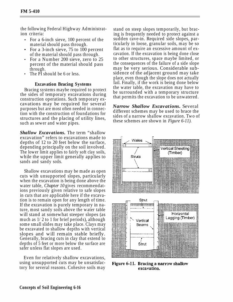
Narrow Shallow Excavations. Severaldifferent schemes may be used to brace thesides of a narrow shallow excavation. Two ofthese schemes are shown in Figure 6-11).
Concepts of Soil Engineering 6-16
FM 5-410
In the first scheme, timber planks aredriven around the boundary of the excavationto form what is called vertical sheeting. Thebottom of the sheeting is kept at or near thebottom of the pit or trench as excavationproceeds. The sheeting is held in place bymeans of horizontal beams called wales.These wales are usually supported againsteach other by means of horizontal memberscalled struts, which extend from one side ofthe excavation to the other. The struts maybe cut slightly long, driven into place, andheld by nails or cleats. They may also be heldin position by wedges or shims. Hydraulic orscrew-type jacks can be used as struts.
The second scheme uses horizontal timberplanks to form what is called horizontal lag-ging. The lagging, in turn, is supported byvertical solid beams and struts. If the excava-tion is quite wide, struts may have to bebraced horizontally or vertically or both.
Bracing systems for shallow excavationsare commonly designed on the basis of ex-perience. Systems of this sort represent casesof incomplete deformation, since the bracingsystem prevents deformation at some pointswhile permitting some deformation at others.
Members used in bracing systems shouldbe strong and stiff. In ordinary work, strutsvary from 4-inch to 6-inch timbers for narrowcuts up to 8-inch by 8-inch timbers for excava-tions 10 or 12 feet wide. Heavier timbers areused if additional safety is desired. Struts arecommonly spaced about 8 feet horizontallyand from 5 to 6 feet vertically. Lagging or
sheeting is customarily made from planksfrom 6 to 12 inches wide, with the minimumthickness usually being about 2 inches.
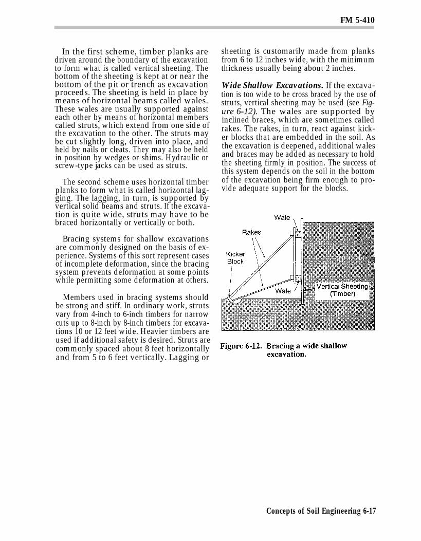
Wide Shallow Excavations. If the excava-tion is too wide to be cross braced by the use ofstruts, vertical sheeting may be used (see Fig-ure 6-12). The wales are supported byinclined braces, which are sometimes calledrakes. The rakes, in turn, react against kick-er blocks that are embedded in the soil. Asthe excavation is deepened, additional walesand braces may be added as necessary to holdthe sheeting firmly in position. The success ofthis system depends on the soil in the bottomof the excavation being firm enough to pro-vide adequate support for the blocks.
Concepts of Soil Engineering 6-17