chapter 24
DESCRIPTION
Chapter 24. Wave Optics. Wave Optics. The wave nature of light is needed to explain various phenomena Interference Diffraction Polarization The particle nature of light was the basis for ray (geometric) optics. Interference. - PowerPoint PPT PresentationTRANSCRIPT
Chapter 24
Wave Optics
Wave Optics The wave nature of light is needed
to explain various phenomena Interference Diffraction Polarization
The particle nature of light was the basis for ray (geometric) optics
Interference Light waves interfere with each
other much like mechanical waves do
All interference associated with light waves arises when the electromagnetic fields that constitute the individual waves combine
Conditions for Interference For sustained interference
between two sources of light to be observed, there are two conditions which must be met The sources must be coherent
They must maintain a constant phase with respect to each other
The waves must have identical wavelengths
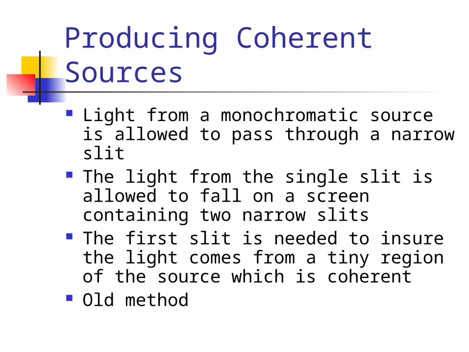
Producing Coherent Sources Light from a monochromatic source is
allowed to pass through a narrow slit The light from the single slit is allowed
to fall on a screen containing two narrow slits
The first slit is needed to insure the light comes from a tiny region of the source which is coherent
Old method
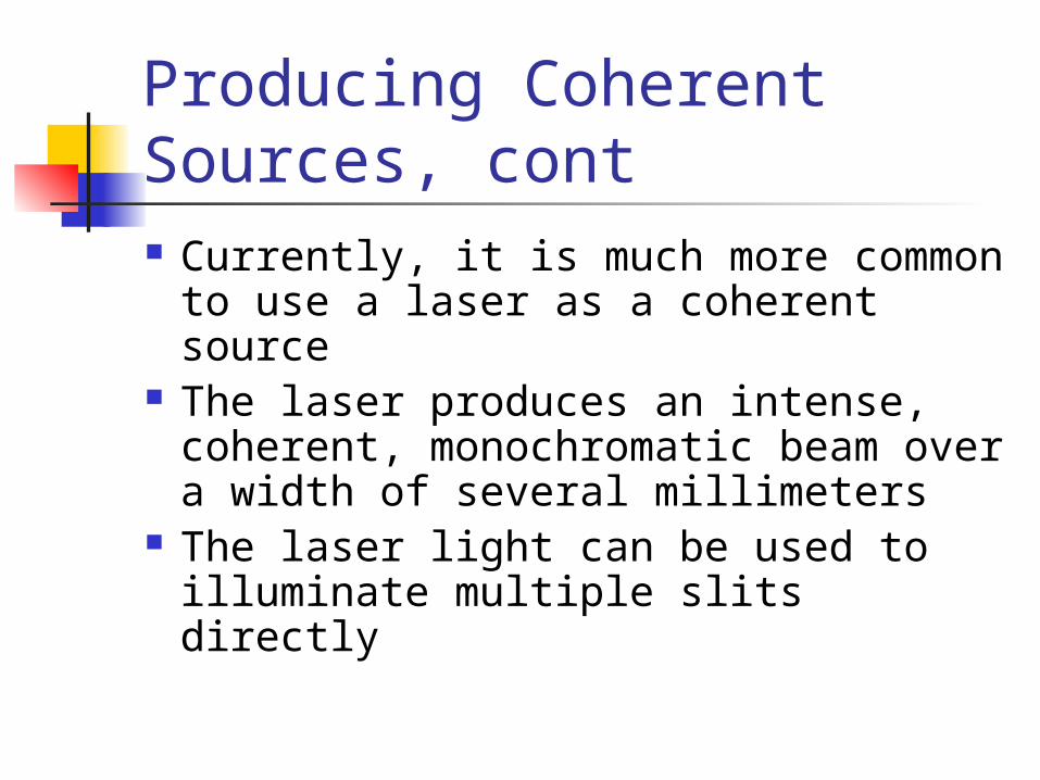
Producing Coherent Sources, cont Currently, it is much more common
to use a laser as a coherent source The laser produces an intense,
coherent, monochromatic beam over a width of several millimeters
The laser light can be used to illuminate multiple slits directly
Young’s Double Slit Experiment Thomas Young first demonstrated
interference in light waves from two sources in 1801
Light is incident on a screen with a narrow slit, So
The light waves emerging from this slit arrive at a second screen that contains two narrow, parallel slits, S1 and S2
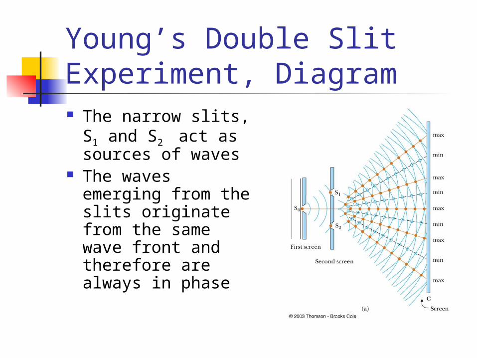
Young’s Double Slit Experiment, Diagram The narrow slits,
S1 and S2 act as sources of waves
The waves emerging from the slits originate from the same wave front and therefore are always in phase
Resulting Interference Pattern The light from the two slits form a
visible pattern on a screen The pattern consists of a series of bright
and dark parallel bands called fringes Constructive interference occurs where
a bright fringe appears Destructive interference results in a
dark fringe
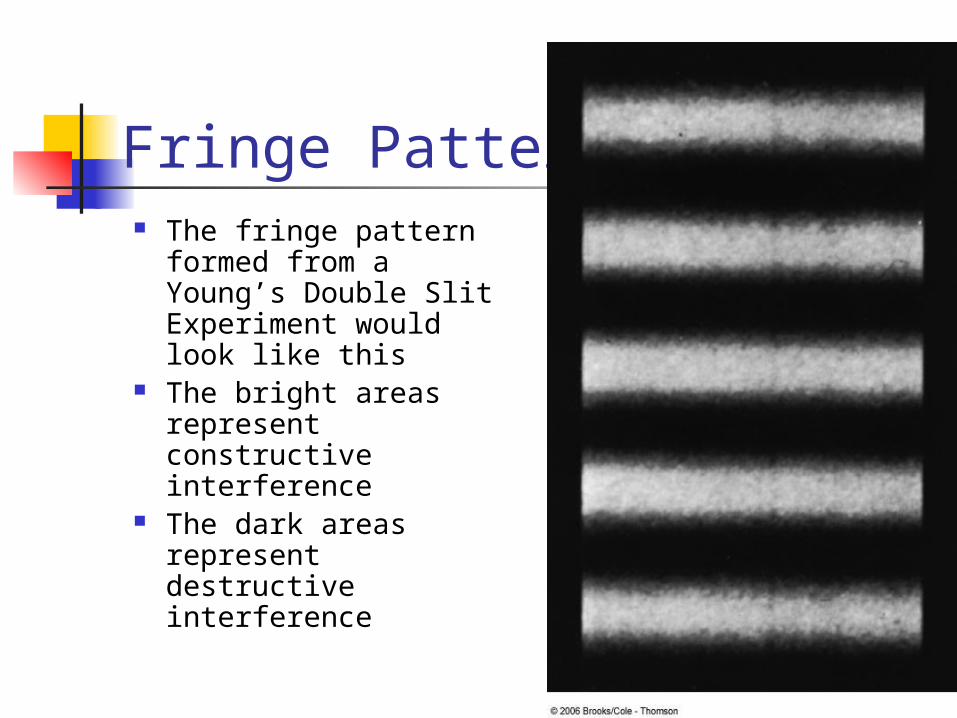
Fringe Pattern The fringe pattern
formed from a Young’s Double Slit Experiment would look like this
The bright areas represent constructive interference
The dark areas represent destructive interference
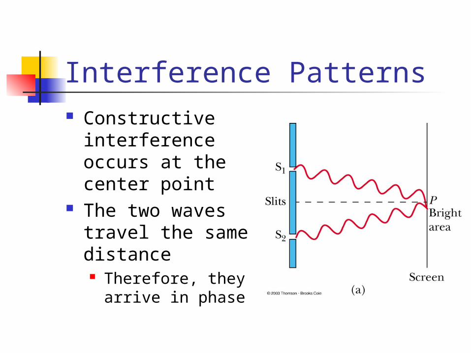
Interference Patterns Constructive
interference occurs at the center point
The two waves travel the same distance Therefore, they
arrive in phase
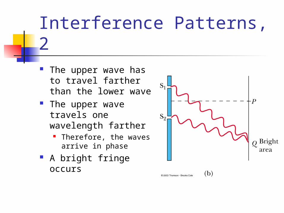
Interference Patterns, 2 The upper wave has
to travel farther than the lower wave
The upper wave travels one wavelength farther
Therefore, the waves arrive in phase
A bright fringe occurs
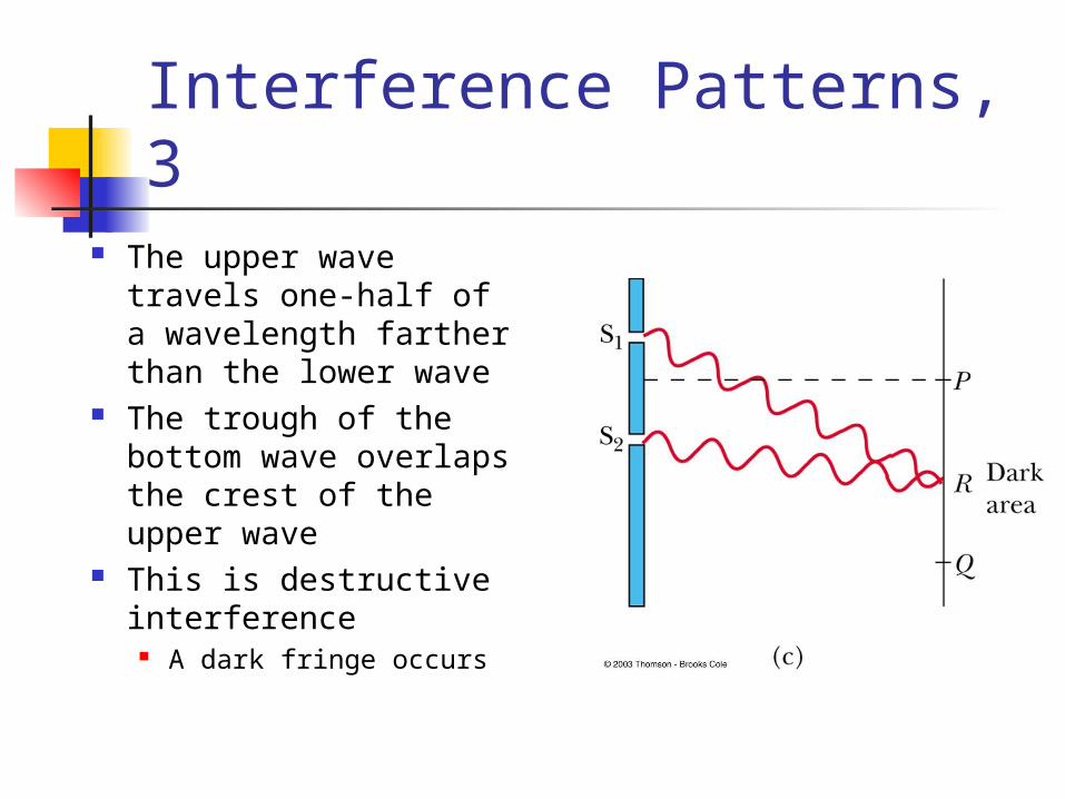
Interference Patterns, 3 The upper wave
travels one-half of a wavelength farther than the lower wave
The trough of the bottom wave overlaps the crest of the upper wave
This is destructive interference
A dark fringe occurs
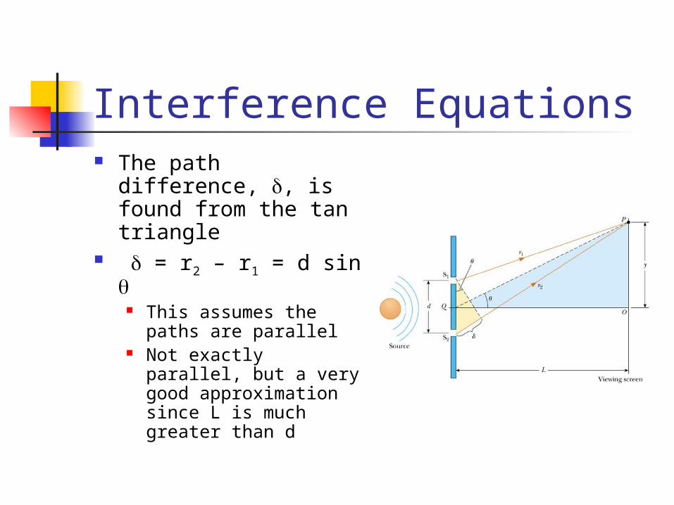
Interference Equations The path difference,
, is found from the tan triangle
= r2 – r1 = d sin This assumes the
paths are parallel Not exactly parallel,
but a very good approximation since L is much greater than d
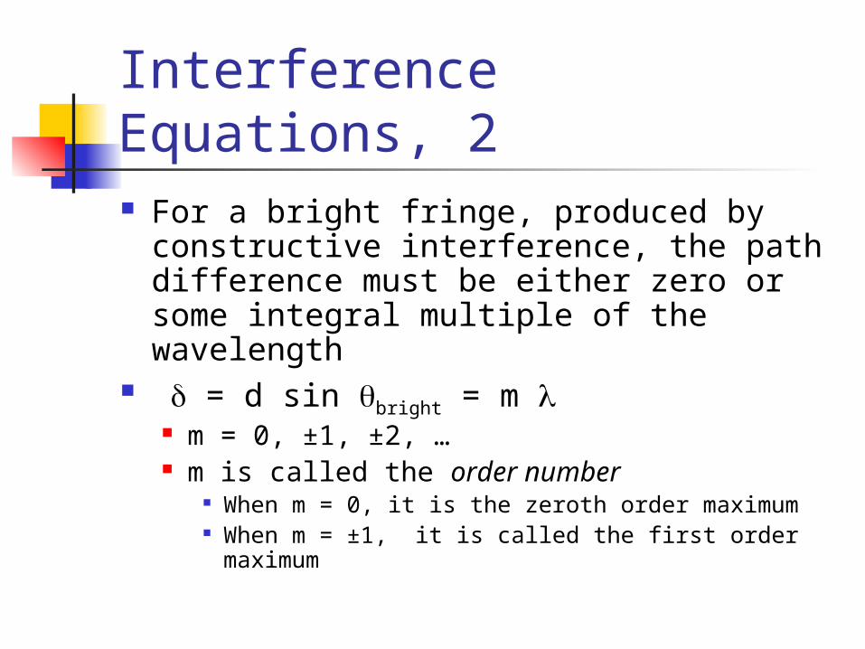
Interference Equations, 2 For a bright fringe, produced by
constructive interference, the path difference must be either zero or some integral multiple of the wavelength
= d sin bright = m m = 0, ±1, ±2, … m is called the order number
When m = 0, it is the zeroth order maximum When m = ±1, it is called the first order
maximum
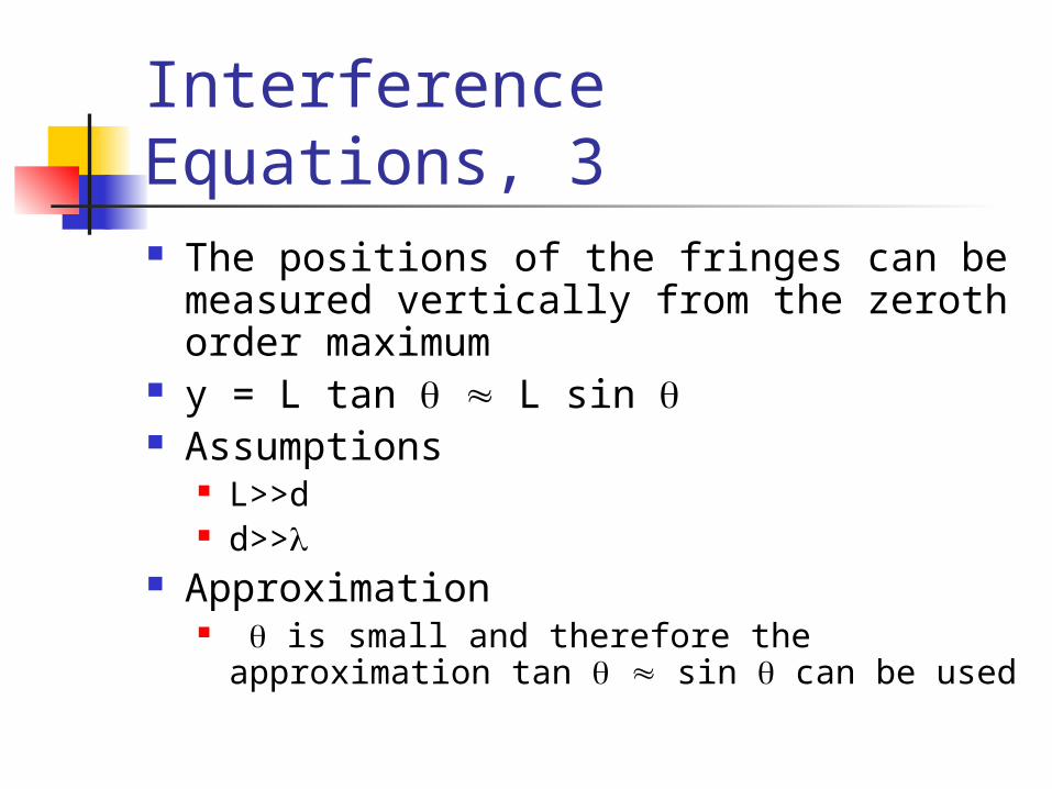
Interference Equations, 3 The positions of the fringes can be
measured vertically from the zeroth order maximum
y = L tan L sin Assumptions
L>>d d>>
Approximation is small and therefore the approximation
tan sin can be used
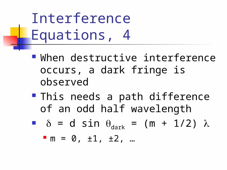
Interference Equations, 4 When destructive interference
occurs, a dark fringe is observed This needs a path difference of an
odd half wavelength = d sin dark = (m + 1/2)
m = 0, ±1, ±2, …
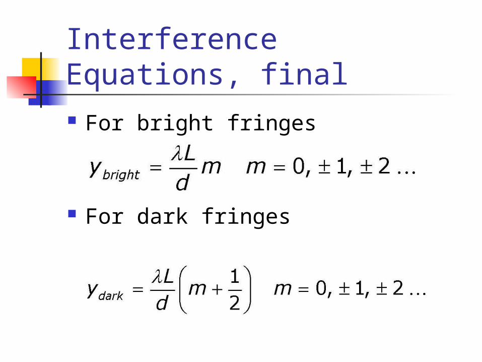
Interference Equations, final For bright fringes
For dark fringes
Uses for Young’s Double Slit Experiment Young’s Double Slit Experiment
provides a method for measuring wavelength of the light
This experiment gave the wave model of light a great deal of credibility It is inconceivable that particles of
light could cancel each other
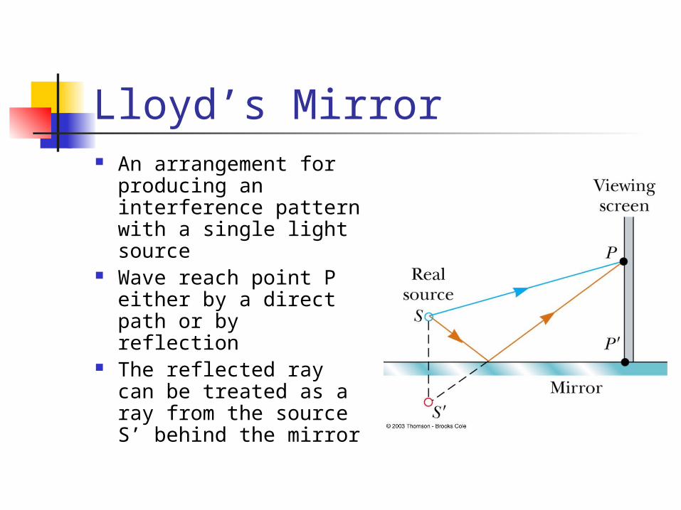
Lloyd’s Mirror An arrangement for
producing an interference pattern with a single light source
Wave reach point P either by a direct path or by reflection
The reflected ray can be treated as a ray from the source S’ behind the mirror
Interference Pattern from the Lloyd’s Mirror An interference pattern is formed The positions of the dark and
bright fringes are reversed relative to pattern of two real sources
This is because there is a 180° phase change produced by the reflection
Phase Changes Due To Reflection
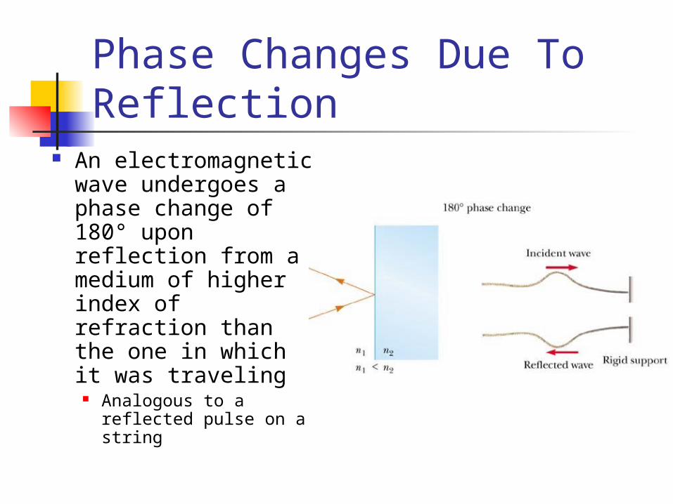
An electromagnetic wave undergoes a phase change of 180° upon reflection from a medium of higher index of refraction than the one in which it was traveling
Analogous to a reflected pulse on a string
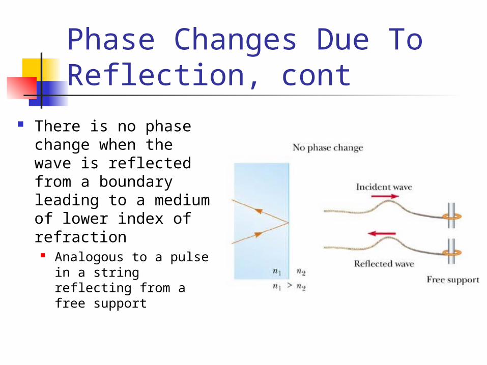
Phase Changes Due To Reflection, cont
There is no phase change when the wave is reflected from a boundary leading to a medium of lower index of refraction
Analogous to a pulse in a string reflecting from a free support
Interference in Thin Films Interference effects are
commonly observed in thin films Examples are soap bubbles and oil on
water The interference is due to the
interaction of the waves reflected from both surfaces of the film
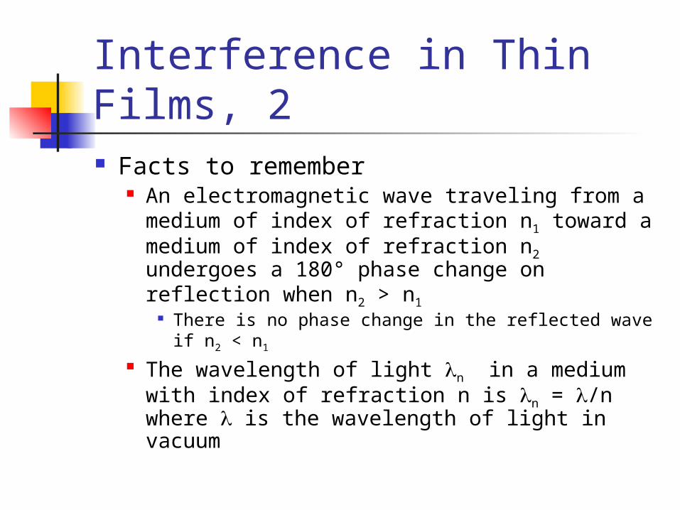
Interference in Thin Films, 2 Facts to remember
An electromagnetic wave traveling from a medium of index of refraction n1 toward a medium of index of refraction n2 undergoes a 180° phase change on reflection when n2 > n1
There is no phase change in the reflected wave if n2 < n1
The wavelength of light n in a medium with index of refraction n is n = /n where is the wavelength of light in vacuum
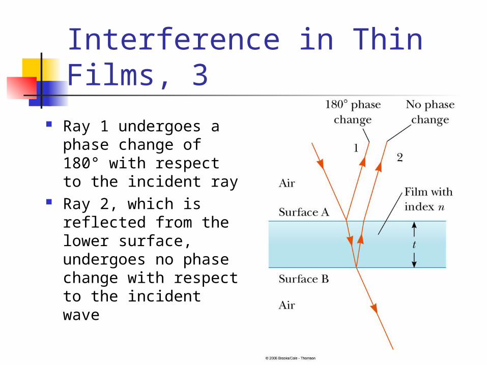
Interference in Thin Films, 3
Ray 1 undergoes a phase change of 180° with respect to the incident ray
Ray 2, which is reflected from the lower surface, undergoes no phase change with respect to the incident wave
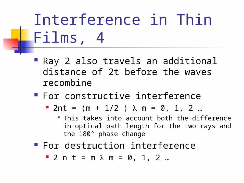
Interference in Thin Films, 4 Ray 2 also travels an additional distance
of 2t before the waves recombine For constructive interference
2nt = (m + 1/2 ) m = 0, 1, 2 … This takes into account both the difference in
optical path length for the two rays and the 180° phase change
For destruction interference 2 n t = m m = 0, 1, 2 …
Interference in Thin Films, 5 Two factors influence interference
Possible phase reversals on reflection Differences in travel distance
The conditions are valid if the medium above the top surface is the same as the medium below the bottom surface
If the thin film is between two different media, one of lower index than the film and one of higher index, the conditions for constructive and destructive interference are reversed
Interference in Thin Films, final Be sure to include two effects
when analyzing the interference pattern from a thin film Path length Phase change
Newton’s Rings Another method for viewing interference is to
place a planoconvex lens on top of a flat glass surface
The air film between the glass surfaces varies in thickness from zero at the point of contact to some thickness t
A pattern of light and dark rings is observed This rings are called Newton’s Rings The particle model of light could not explain the
origin of the rings Newton’s Rings can be used to test optical
lenses
Problem Solving Strategy with Thin Films, 1 Identify the thin film causing the
interference Determine the indices of refraction
in the film and the media on either side of it
Determine the number of phase reversals: zero, one or two
Problem Solving with Thin Films, 2 The interference is constructive if
the path difference is an integral multiple of and destructive if the path difference is an odd half multiple of The conditions are reversed if one of
the waves undergoes a phase change on reflection
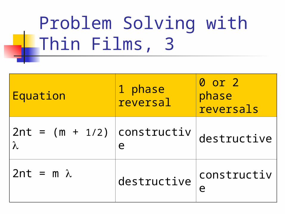
Problem Solving with Thin Films, 3
Equation1 phase reversal
0 or 2 phase reversals
2nt = (m + 1/2) constructive destructive
2nt = m destructive constructive
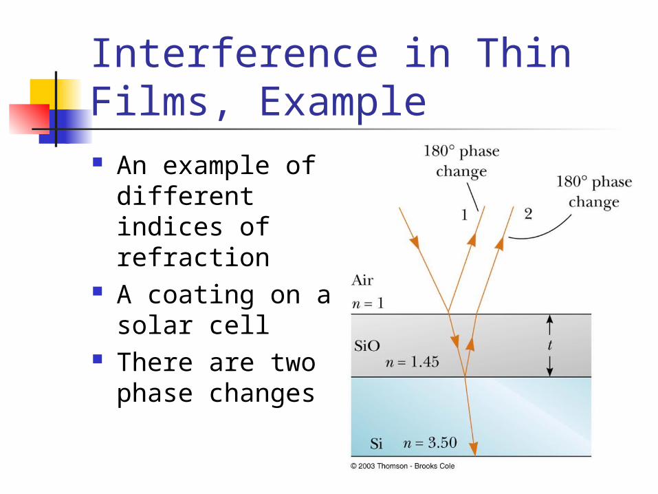
Interference in Thin Films, Example An example of
different indices of refraction
A coating on a solar cell
There are two phase changes
CD’s and DVD’s Data is stored digitally
A series of ones and zeros read by laser light reflected from the disk
Strong reflections correspond to constructive interference These reflections are chosen to represent
zeros Weak reflections correspond to
destructive interference These reflections are chosen to represent
ones
CD’s and Thin Film Interference A CD has multiple tracks
The tracks consist of a sequence of pits of varying length formed in a reflecting information layer
The pits appear as bumps to the laser beam The laser beam shines on the metallic
layer through a clear plastic coating
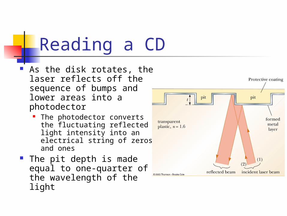
Reading a CD As the disk rotates, the
laser reflects off the sequence of bumps and lower areas into a photodector
The photodector converts the fluctuating reflected light intensity into an electrical string of zeros and ones
The pit depth is made equal to one-quarter of the wavelength of the light
Reading a CD, cont When the laser beam hits a rising or
falling bump edge, part of the beam reflects from the top of the bump and part from the lower adjacent area This ensures destructive interference and
very low intensity when the reflected beams combine at the detector
The bump edges are read as ones The flat bump tops and intervening flat
plains are read as zeros
DVD’s DVD’s use shorter wavelength
lasers The track separation, pit depth and
minimum pit length are all smaller Therefore, the DVD can store about
30 times more information than a CD
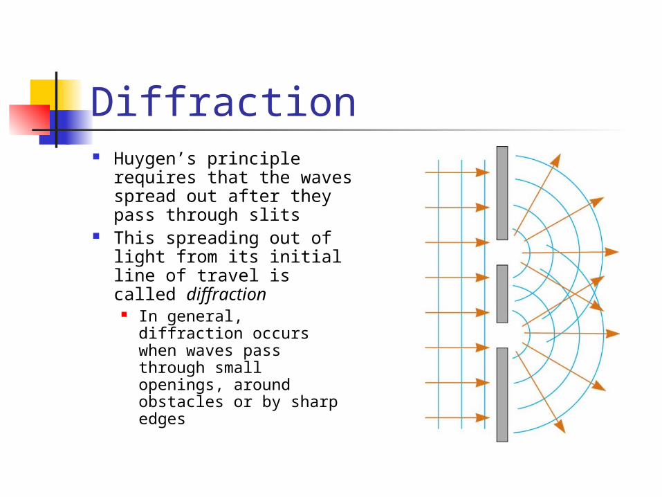
Diffraction Huygen’s principle
requires that the waves spread out after they pass through slits
This spreading out of light from its initial line of travel is called diffraction
In general, diffraction occurs when waves pass through small openings, around obstacles or by sharp edges
Diffraction, 2 A single slit placed between a distant
light source and a screen produces a diffraction pattern It will have a broad, intense central band The central band will be flanked by a series
of narrower, less intense secondary bands Called secondary maxima
The central band will also be flanked by a series of dark bands
Called minima
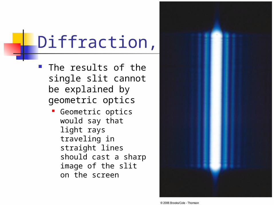
Diffraction, 3 The results of the
single slit cannot be explained by geometric optics
Geometric optics would say that light rays traveling in straight lines should cast a sharp image of the slit on the screen
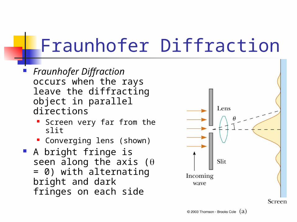
Fraunhofer Diffraction Fraunhofer Diffraction
occurs when the rays leave the diffracting object in parallel directions
Screen very far from the slit Converging lens (shown)
A bright fringe is seen along the axis ( = 0) with alternating bright and dark fringes on each side
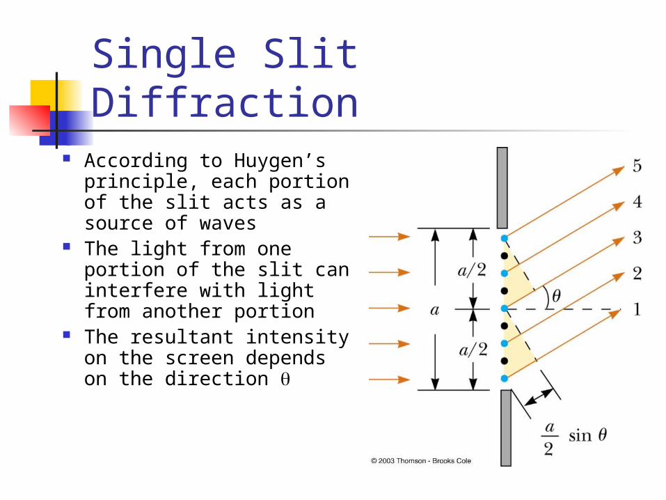
Single Slit Diffraction According to Huygen’s
principle, each portion of the slit acts as a source of waves
The light from one portion of the slit can interfere with light from another portion
The resultant intensity on the screen depends on the direction
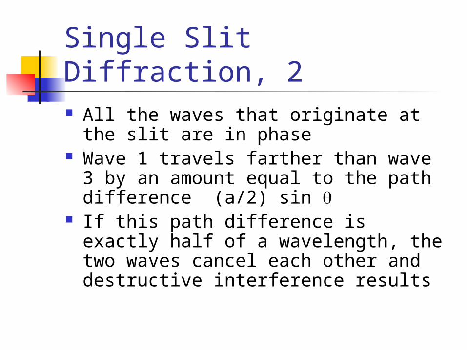
Single Slit Diffraction, 2 All the waves that originate at the slit
are in phase Wave 1 travels farther than wave 3 by
an amount equal to the path difference (a/2) sin
If this path difference is exactly half of a wavelength, the two waves cancel each other and destructive interference results
Single Slit Diffraction, 3 In general, destructive interference
occurs for a single slit of width a when sin dark = m / a m = 1, 2, 3, …
Doesn’t give any information about the variations in intensity along the screen
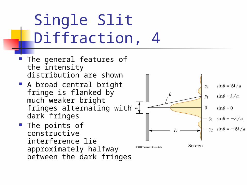
Single Slit Diffraction, 4 The general features of
the intensity distribution are shown
A broad central bright fringe is flanked by much weaker bright fringes alternating with dark fringes
The points of constructive interference lie approximately halfway between the dark fringes

Diffraction Grating The diffracting grating consists of
many equally spaced parallel slits A typical grating contains several
thousand lines per centimeter The intensity of the pattern on the
screen is the result of the combined effects of interference and diffraction
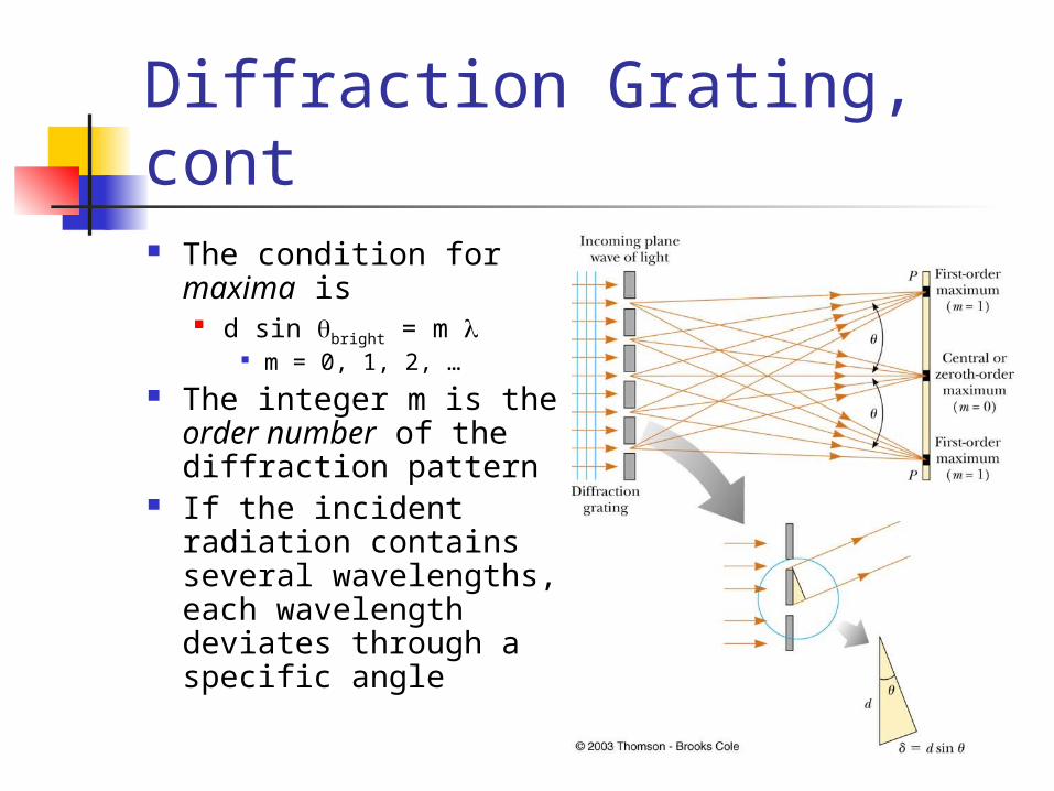
Diffraction Grating, cont The condition for
maxima is d sin bright = m
m = 0, 1, 2, … The integer m is the
order number of the diffraction pattern
If the incident radiation contains several wavelengths, each wavelength deviates through a specific angle
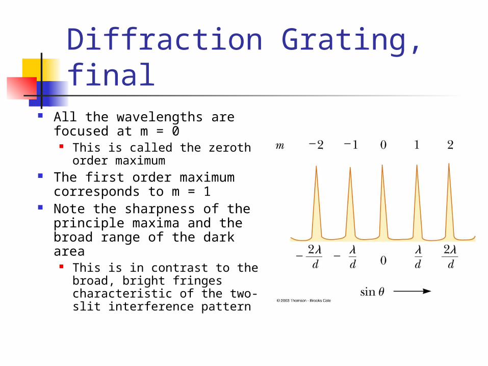
Diffraction Grating, final All the wavelengths are
focused at m = 0 This is called the zeroth
order maximum The first order maximum
corresponds to m = 1 Note the sharpness of the
principle maxima and the broad range of the dark area
This is in contrast to the broad, bright fringes characteristic of the two-slit interference pattern
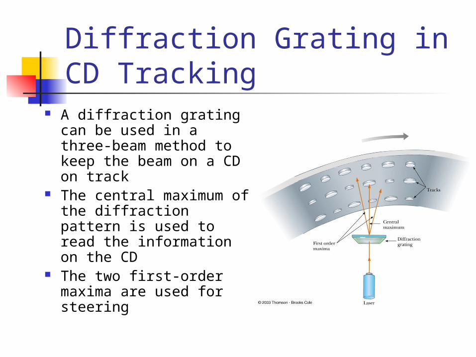
Diffraction Grating in CD Tracking
A diffraction grating can be used in a three-beam method to keep the beam on a CD on track
The central maximum of the diffraction pattern is used to read the information on the CD
The two first-order maxima are used for steering
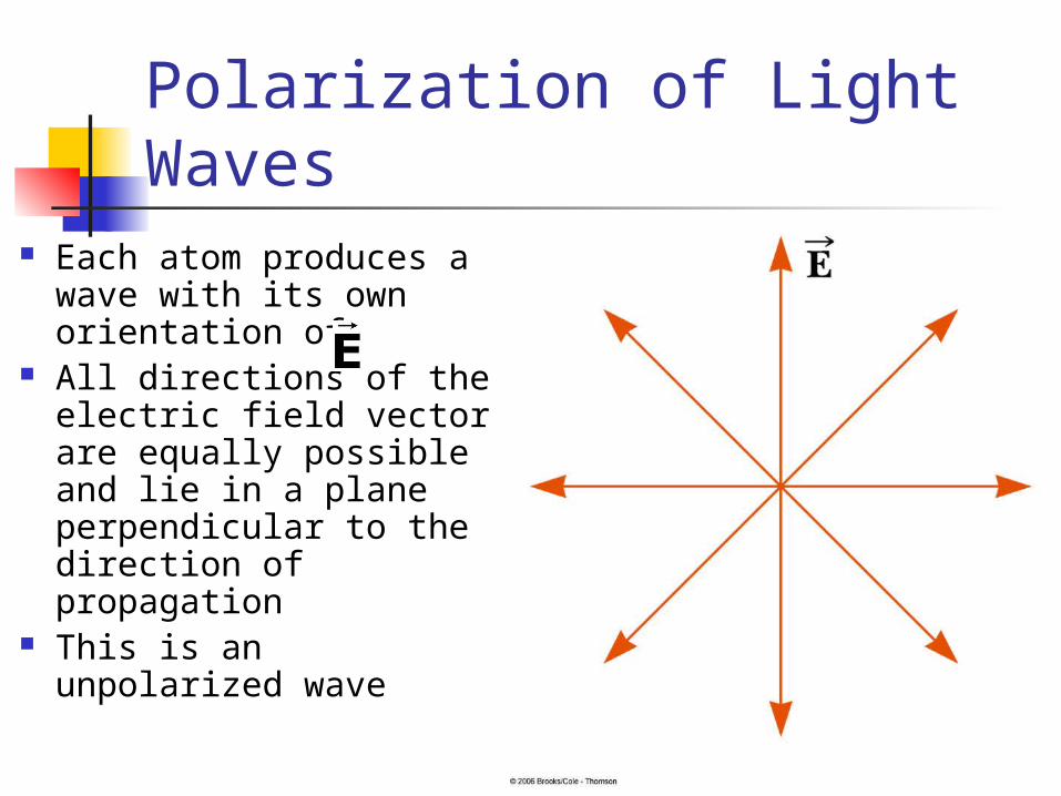
Polarization of Light Waves Each atom produces a
wave with its own orientation of
All directions of the electric field vector are equally possible and lie in a plane perpendicular to the direction of propagation
This is an unpolarized wave
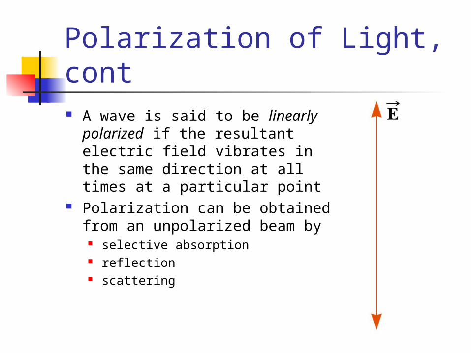
Polarization of Light, cont A wave is said to be linearly
polarized if the resultant electric field vibrates in the same direction at all times at a particular point
Polarization can be obtained from an unpolarized beam by
selective absorption reflection scattering
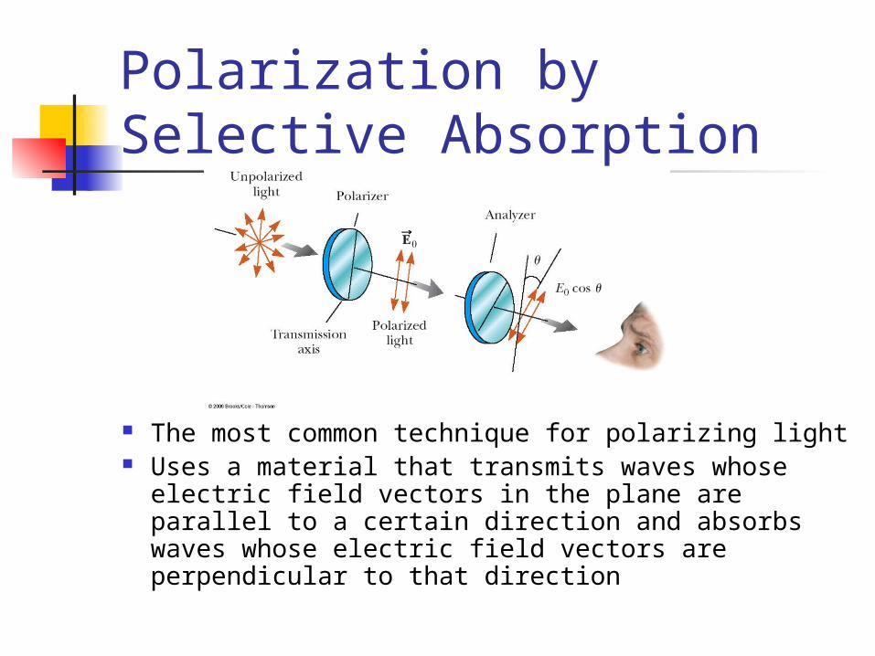
Polarization by Selective Absorption
The most common technique for polarizing light Uses a material that transmits waves whose
electric field vectors in the plane are parallel to a certain direction and absorbs waves whose electric field vectors are perpendicular to that direction
Selective Absorption, cont E. H. Land discovered a material
that polarizes light through selective absorption He called the material Polaroid The molecules readily absorb light
whose electric field vector is parallel to their lengths and transmit light whose electric field vector is perpendicular to their lengths
Selective Absorption, final The intensity of the polarized beam
transmitted through the second polarizing sheet (the analyzer) varies as I = Io cos2
Io is the intensity of the polarized wave incident on the analyzer
This is known as Malus’ Law and applies to any two polarizing materials whose transmission axes are at an angle of to each other
Polarization by Reflection When an unpolarized light beam is reflected
from a surface, the reflected light is Completely polarized Partially polarized Unpolarized
It depends on the angle of incidence If the angle is 0° or 90°, the reflected beam is
unpolarized For angles between this, there is some degree of
polarization For one particular angle, the beam is completely
polarized
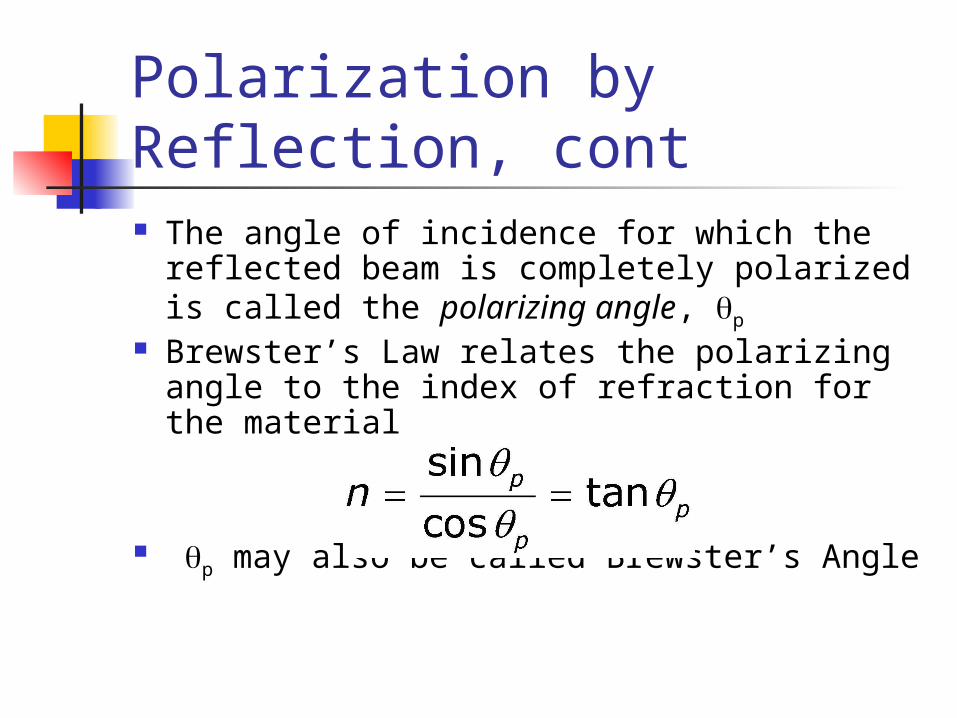
Polarization by Reflection, cont The angle of incidence for which the
reflected beam is completely polarized is called the polarizing angle, p
Brewster’s Law relates the polarizing angle to the index of refraction for the material
p may also be called Brewster’s Angle
Polarization by Scattering When light is incident on a system
of particles, the electrons in the medium can absorb and reradiate part of the light This process is called scattering
An example of scattering is the sunlight reaching an observer on the earth becoming polarized
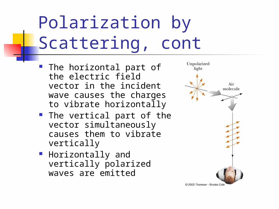
Polarization by Scattering, cont The horizontal part of the
electric field vector in the incident wave causes the charges to vibrate horizontally
The vertical part of the vector simultaneously causes them to vibrate vertically
Horizontally and vertically polarized waves are emitted
Optical Activity Certain materials display the
property of optical activity A substance is optically active if it
rotates the plane of polarization of transmitted light
Optical activity occurs in a material because of an asymmetry in the shape of its constituent materials
Liquid Crystals A liquid crystal is a substance with
properties intermediate between those of a crystalline solid and those of a liquid
The molecules of the substance are more orderly than those of a liquid but less than those in a pure crystalline solid
To create a display, the liquid crystal is placed between two glass plates and electrical contacts are made to the liquid crystal
A voltage is applied across any segment in the display and that segment turns on
Liquid Crystals, 2
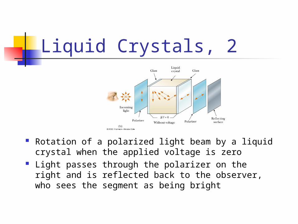
Rotation of a polarized light beam by a liquid crystal when the applied voltage is zero
Light passes through the polarizer on the right and is reflected back to the observer, who sees the segment as being bright
Liquid Crystals, 3
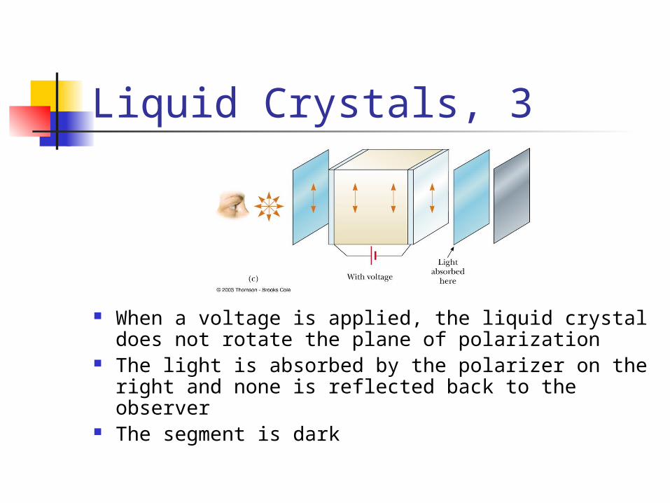
When a voltage is applied, the liquid crystal does not rotate the plane of polarization
The light is absorbed by the polarizer on the right and none is reflected back to the observer
The segment is dark
Liquid Crystals, final Changing the applied voltage in a
precise pattern can Tick off the seconds on a watch Display a letter on a computer display