chapter 20 electric circuits - woodstockwsapphysics.weebly.com/uploads/8/4/4/8/84486476/...chapter...
TRANSCRIPT
Chapter 20 Electric Circuits
230
Chapter 20 ELECTRIC CIRCUITS PREVIEW Conventional current is the flow of positive charges though a closed circuit. The current through a resistance and the voltage which produces it are related by Ohm’s law. Power is the rate at which energy is consumed in a circuit through the resistors. Resistors in a circuit may be connected in series or in parallel. If a capacitor is placed in a circuit with a resistor, the current in the circuit becomes time-dependent as the capacitor charges or discharges. QUICK REFERENCE Important Terms ammeter
device used to measure electrical current ampere
unit of electrical current equal to one coulomb per second battery
device that converts chemical energy into electrical energy , creating a potential difference (voltage)
capacitive time constant the product of the resistance and the capacitance in a circuit; at a time equal to the product RC, the capacitor has reached 63% of its maximum charge
capacitor two oppositely charged conductors used to store charge and energy in an electric field between them
direct current electric current whose flow of charges is in one direction only
electric circuit a continuous closed path in which electric charges can flow
electric current flow of charged particles; conventionally, the flow of positive charges
electric power the rate at which work is done or energy is dissipated through a resistor
electrical resistance the ratio of the voltage across a device to the current running through it
Chapter 20 Electric Circuits
231
electron flow
the movement of electrons through a conductor; electron flow is equal and opposite to conventional current flow
emf electromotive force; another name for voltage
equivalent resistance the single resistance that could replace the individual resistances in a circuit and produce the same result
ohm the SI unit for resistance equal to one volt per ampere
Ohm’s law the ratio of voltage to current in a circuit is a constant called resistance
parallel circuit an electric circuit which has two or more paths for the current to follow, allowing each branch to function independently of the others
resistivity the constant which relates the resistance of a resistor to its length and cross- sectional area
resistor device designed to have a specific resistance
schematic diagram a diagram using special symbols to represent a circuit
series circuit an electric circuit in which devices are arranged so that charge flows through each equally.
terminal voltage the actual voltage across the positive and negative terminals of a battery, which is usually lowered by the internal resistance of the battery
voltage the potential difference between the positive and negative sides of a circuit element
watt the SI unit for power equal to one joule of energy per second
Chapter 20 Electric Circuits
232
Equations and Symbols
RCCQQVCVU
CVqCCCC
CCCCRRRR
RRRRIVPALR
IVR
tqI
E
s
P
p
s
=
===
=
+++=
+++=
+++=
+++==
=
=
DD
=
t
r
22
321
321
321
321
21
21
21
...1111...
...1111...
where I = current Δq = amount of charge passing a given point Δt = time interval R = resistance V = voltage P = power RS = total resistance in series RP = total resistance in parallel CP = total capacitance in parallel CS = total capacitance in series q = charge UE = electrical energy stored in a capacitor τ = capacitive time constant
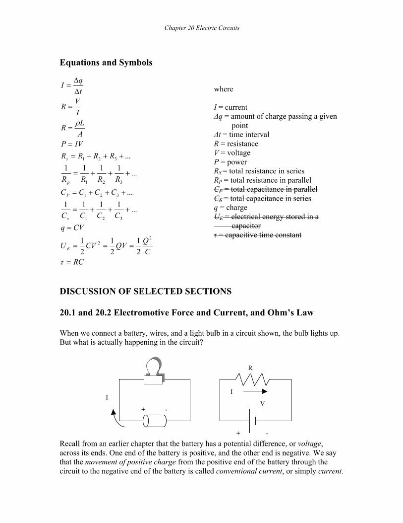
DISCUSSION OF SELECTED SECTIONS 20.1 and 20.2 Electromotive Force and Current, and Ohm’s Law When we connect a battery, wires, and a light bulb in a circuit shown, the bulb lights up. But what is actually happening in the circuit?
Recall from an earlier chapter that the battery has a potential difference, or voltage, across its ends. One end of the battery is positive, and the other end is negative. We say that the movement of positive charge from the positive end of the battery through the circuit to the negative end of the battery is called conventional current, or simply current.
+ -
R
V
I
+ -
I
Area
+q
Chapter 20 Electric Circuits
233
Current is the amount of charge moving through a cross-sectional area of a conductor per second, and the unit for current is the coulomb/second, or ampere. We use the symbol I for current. Conventional current is defined as the flow of positive charge on the AP Physics B exam, although electrons are actually moving in the wire. In a circuit such as the one shown above, the current is directly proportional to the voltage. The ratio of voltage to current is a constant defined as the resistance, and is measured in ohms (W), or volts/amp. The relationship between voltage, current, and resistance is called Ohm’s law:
IVR =
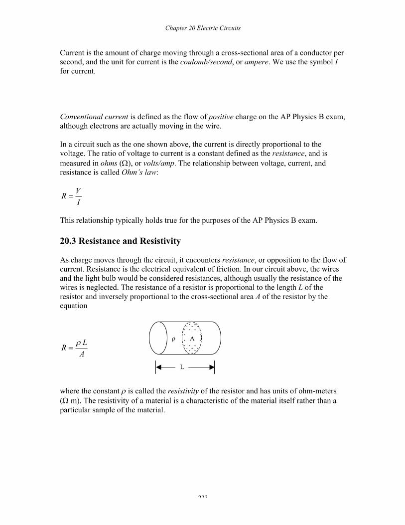
This relationship typically holds true for the purposes of the AP Physics B exam. 20.3 Resistance and Resistivity As charge moves through the circuit, it encounters resistance, or opposition to the flow of current. Resistance is the electrical equivalent of friction. In our circuit above, the wires and the light bulb would be considered resistances, although usually the resistance of the wires is neglected. The resistance of a resistor is proportional to the length L of the resistor and inversely proportional to the cross-sectional area A of the resistor by the equation
ALR r
=
where the constant r is called the resistivity of the resistor and has units of ohm-meters (W m). The resistivity of a material is a characteristic of the material itself rather than a particular sample of the material.
A
L
ρ
Chapter 20 Electric Circuits
234
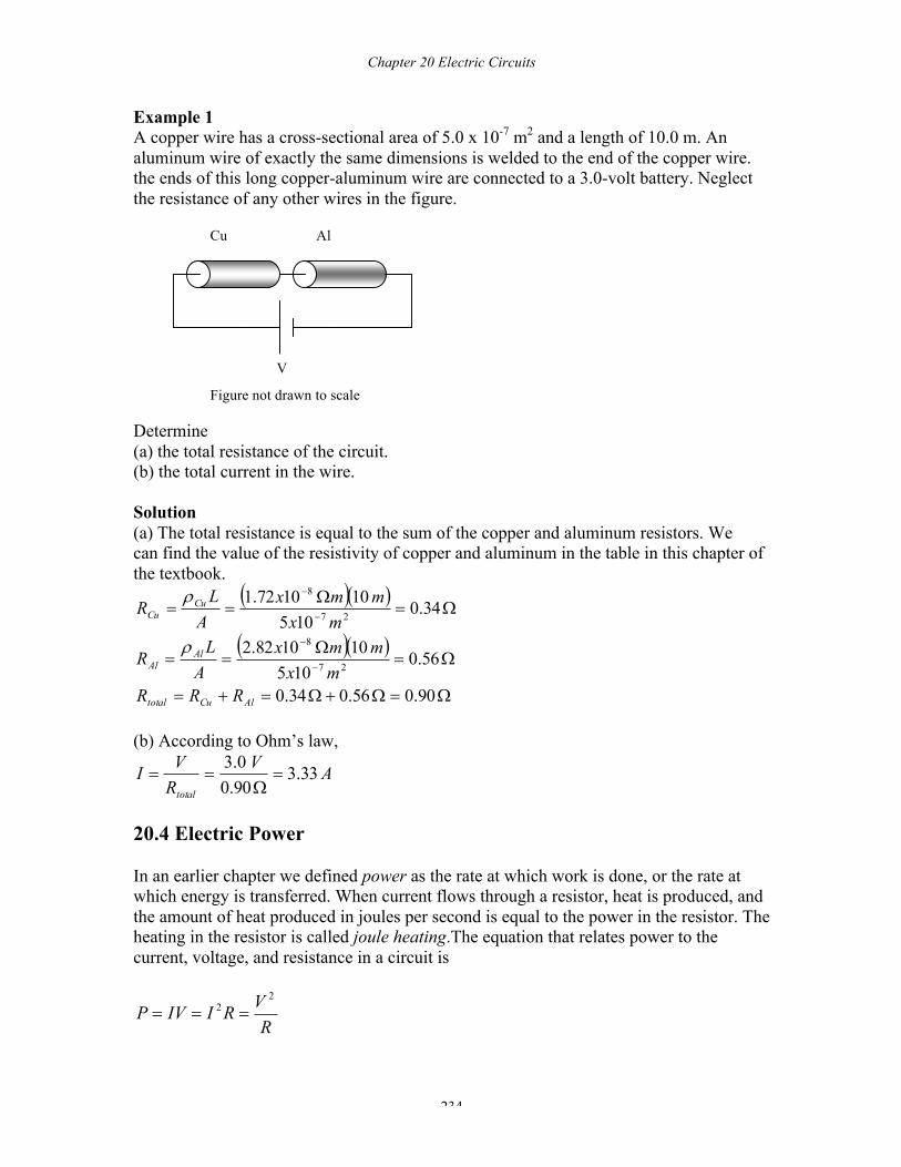
Example 1 A copper wire has a cross-sectional area of 5.0 x 10⁻⁷ m2 and a length of 10.0 m. An aluminum wire of exactly the same dimensions is welded to the end of the copper wire. the ends of this long copper-aluminum wire are connected to a 3.0-volt battery. Neglect the resistance of any other wires in the figure.
Determine (a) the total resistance of the circuit. (b) the total current in the wire. Solution (a) The total resistance is equal to the sum of the copper and aluminum resistors. We can find the value of the resistivity of copper and aluminum in the table in this chapter of the textbook.
( )( )
( )( )
W=W+W=+=
W=W
==
W=W
==
-
-
-
-
90.056.034.0
56.0105
101082.2
34.0105
101072.1
27
8
27
8
AlCutotal
AlAl
CuCu
RRRmx
mmxAL
R
mxmmx
AL
R
r
r
(b) According to Ohm’s law,
AVRVItotal
33.390.00.3
=W
==
20.4 Electric Power In an earlier chapter we defined power as the rate at which work is done, or the rate at which energy is transferred. When current flows through a resistor, heat is produced, and the amount of heat produced in joules per second is equal to the power in the resistor. The heating in the resistor is called joule heating.The equation that relates power to the current, voltage, and resistance in a circuit is
RVRIIVP2
2 ===
Cu Al
V
Figure not drawn to scale
Chapter 20 Electric Circuits
235
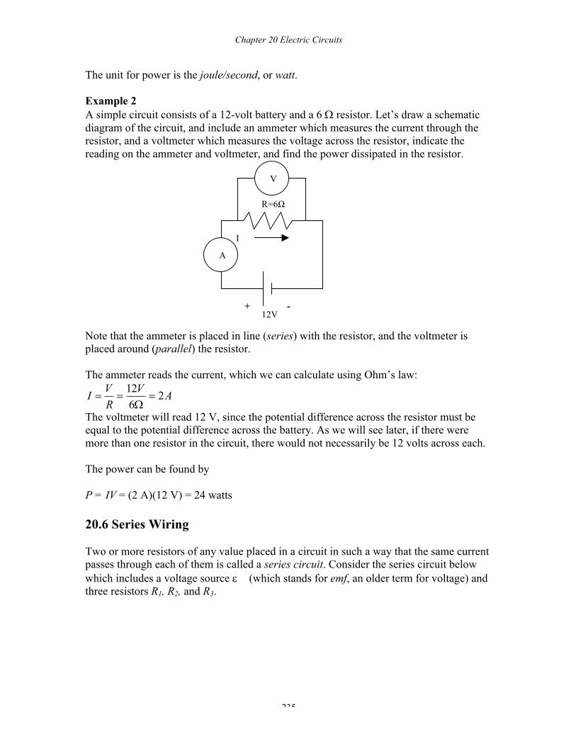
The unit for power is the joule/second, or watt. Example 2 A simple circuit consists of a 12-volt battery and a 6 W resistor. Let’s draw a schematic diagram of the circuit, and include an ammeter which measures the current through the resistor, and a voltmeter which measures the voltage across the resistor, indicate the reading on the ammeter and voltmeter, and find the power dissipated in the resistor. Note that the ammeter is placed in line (series) with the resistor, and the voltmeter is placed around (parallel) the resistor. The ammeter reads the current, which we can calculate using Ohm’s law:
AVRVI 2
612
=W
==
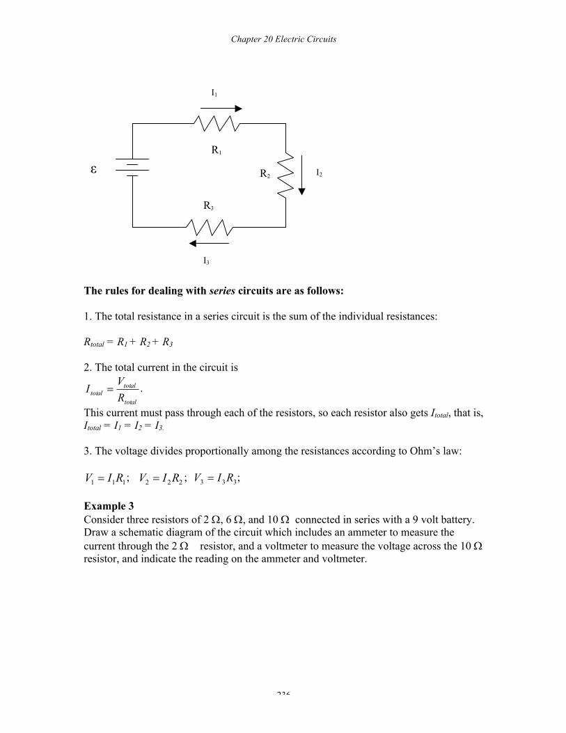
The voltmeter will read 12 V, since the potential difference across the resistor must be equal to the potential difference across the battery. As we will see later, if there were more than one resistor in the circuit, there would not necessarily be 12 volts across each. The power can be found by P = IV = (2 A)(12 V) = 24 watts 20.6 Series Wiring Two or more resistors of any value placed in a circuit in such a way that the same current passes through each of them is called a series circuit. Consider the series circuit below which includes a voltage source e (which stands for emf, an older term for voltage) and three resistors R1, R2, and R3.
R=6Ω
I
12V
V
+ -
A
Chapter 20 Electric Circuits
236
The rules for dealing with series circuits are as follows: 1. The total resistance in a series circuit is the sum of the individual resistances: Rtotal = R1 + R2 + R3 2. The total current in the circuit is
total
totaltotal R
VI = .
This current must pass through each of the resistors, so each resistor also gets Itotal, that is, Itotal = I1 = I2 = I3. 3. The voltage divides proportionally among the resistances according to Ohm’s law:
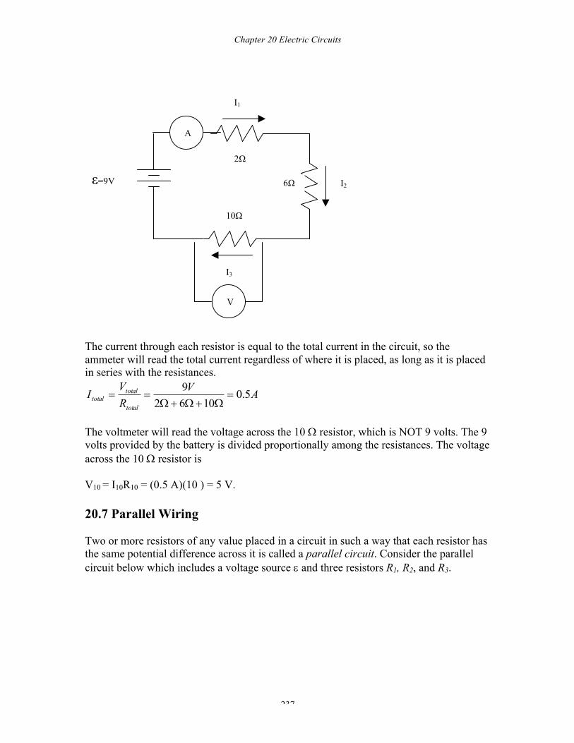
111 RIV = ; 222 RIV = ; 333 RIV = ; Example 3 Consider three resistors of 2 W, 6 W, and 10 W connected in series with a 9 volt battery. Draw a schematic diagram of the circuit which includes an ammeter to measure the current through the 2 W resistor, and a voltmeter to measure the voltage across the 10 W resistor, and indicate the reading on the ammeter and voltmeter.
ε R1
R2
R3
I1
I3
I2
Chapter 20 Electric Circuits
237
The current through each resistor is equal to the total current in the circuit, so the ammeter will read the total current regardless of where it is placed, as long as it is placed in series with the resistances.
AVRV
Itotal
totaltotal 5.0
10629
=W+W+W
==
The voltmeter will read the voltage across the 10 W resistor, which is NOT 9 volts. The 9 volts provided by the battery is divided proportionally among the resistances. The voltage across the 10 W resistor is V10 = I10R10 = (0.5 A)(10 ) = 5 V. 20.7 Parallel Wiring Two or more resistors of any value placed in a circuit in such a way that each resistor has the same potential difference across it is called a parallel circuit. Consider the parallel circuit below which includes a voltage source e and three resistors R1, R2, and R3.
ε=9V
2Ω
6Ω
10Ω
I1
I3
I2
V
A
Chapter 20 Electric Circuits
238
The rules for dealing with parallel circuits are as follows: 1. The total resistance in a parallel circuit is given by the equation
321
1111RRRRtotal
++=
2. The voltage across each resistance is the same: Vtotal = V1 = V2 = V3 3. The current divides in an inverse proportion to the resistance:
1
11 RVI = ;
2
22 RVI = ;
3
33 RV
I =
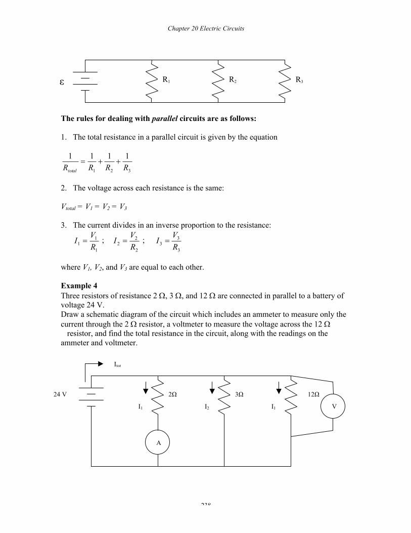
where V1, V2, and V3 are equal to each other. Example 4 Three resistors of resistance 2 W, 3 W, and 12 W are connected in parallel to a battery of voltage 24 V. Draw a schematic diagram of the circuit which includes an ammeter to measure only the current through the 2 W resistor, a voltmeter to measure the voltage across the 12 W resistor, and find the total resistance in the circuit, along with the readings on the ammeter and voltmeter.
ε R1 R2 R3
24 V 2Ω
3Ω
12Ω
I1
I2
I1
Itot
A
V
Chapter 20 Electric Circuits
239
The total resistance in the circuit is found by
W=
W+
W+
W=
W+
W+
W=++=
1211
121
124
126
121
31
211111
321 RRRRtotal
Notice that this fraction is not the total resistance, but totalR1 . Thus, the total resistance in
this circuit must be 1112 W.
Since the ammeter is placed in series only with the 2 W resistance, it will measure the current passing only through the 2W resistance. Recognizing that the voltage is the same (24 V) across each resistance, we have that
AVRVI 12
224
2
22 =
W==
Each resistance is connected across the 24 V battery, so the voltage across the 10 W resistance is 24 V. Note that the equation for the total resistance in parallel comes from the fact that the total current is the sum of the individual currents in the circuit, and each resistor gets the same
voltage: ...2
2
1
1 ++=RV
RV
RV
total
total , where all the V ’s are equal.
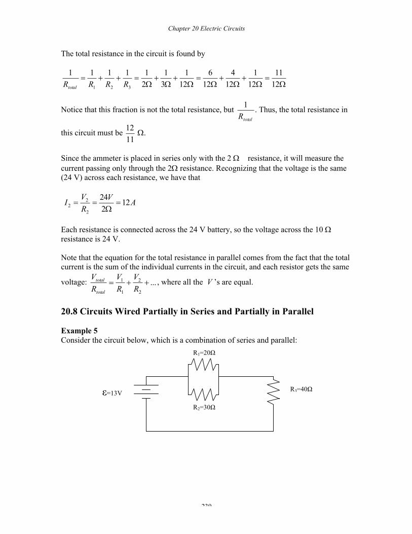
20.8 Circuits Wired Partially in Series and Partially in Parallel Example 5 Consider the circuit below, which is a combination of series and parallel:
ε=13V
R1=20Ω
R2=30Ω
R3=40Ω
Chapter 20 Electric Circuits
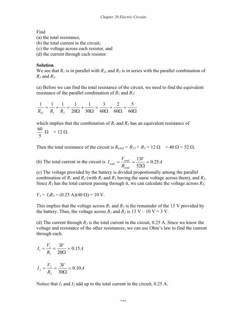
240
Find (a) the total resistance, (b) the total current in the circuit, (c) the voltage across each resistor, and (d) the current through each resistor. Solution We see that R1 is in parallel with R2, and R3 is in series with the parallel combination of R1 and R2. (a) Before we can find the total resistance of the circuit, we need to find the equivalent resistance of the parallel combination of R1 and R2:
W=
W+
W=
W+
W=+=
605
602
603
301
201111
2112 RRR
which implies that the combination of R1 and R2 has an equivalent resistance of
560 W = 12 W.
Then the total resistance of the circuit is Rtotal = R12 + R3 = 12 W + 40 W = 52 W.
(b) The total current in the circuit is AVRV
Itotal
totaltotal 25.0
5213
=W
==
(c) The voltage provided by the battery is divided proportionally among the parallel combination of R1 and R2 (with R1 and R2 having the same voltage across them), and R3. Since R3 has the total current passing through it, we can calculate the voltage across R3: V3 = I3R3 = (0.25 A)(40 W) = 10 V. This implies that the voltage across R1 and R2 is the remainder of the 13 V provided by the battery. Thus, the voltage across R1 and R2 is 13 V – 10 V = 3 V. (d) The current through R3 is the total current in the circuit, 0.25 A. Since we know the voltage and resistance of the other resistances, we can use Ohm’s law to find the current through each.
AVRVI 15.0
203
1
11 =
W==
AVRVI 10.0
303
2
22 =
W==
Notice that I1 and I2 add up to the total current in the circuit, 0.25 A.
Chapter 20 Electric Circuits
241
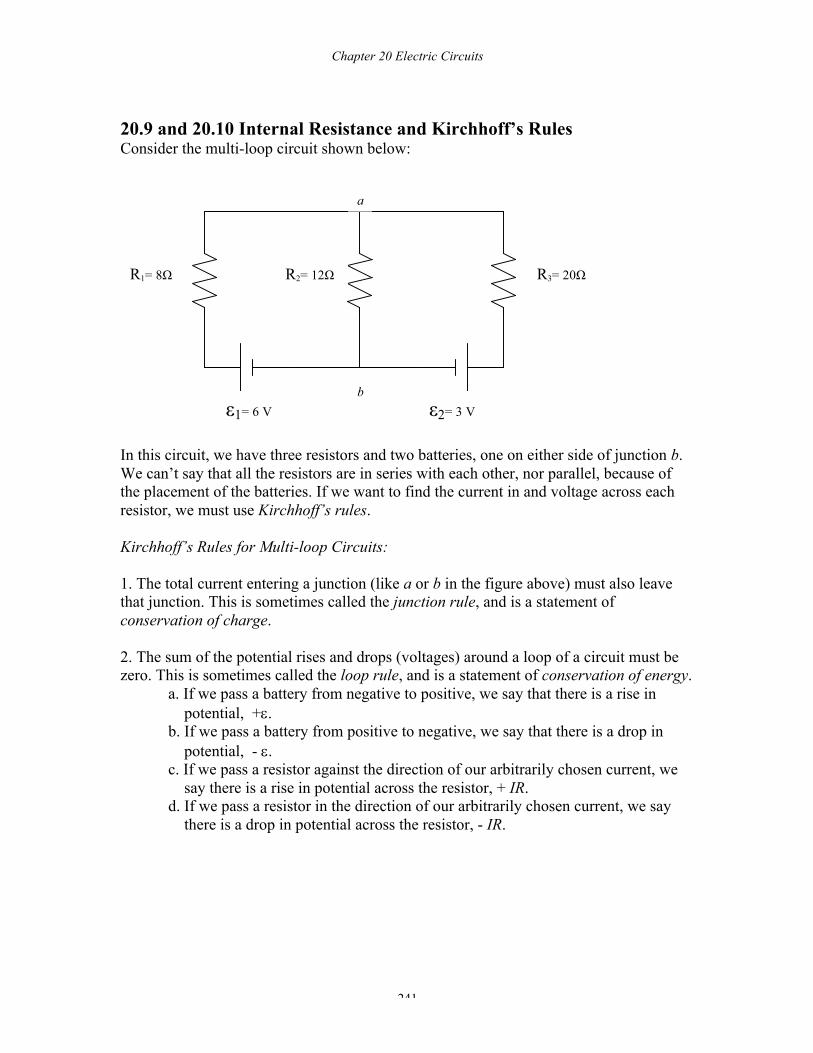
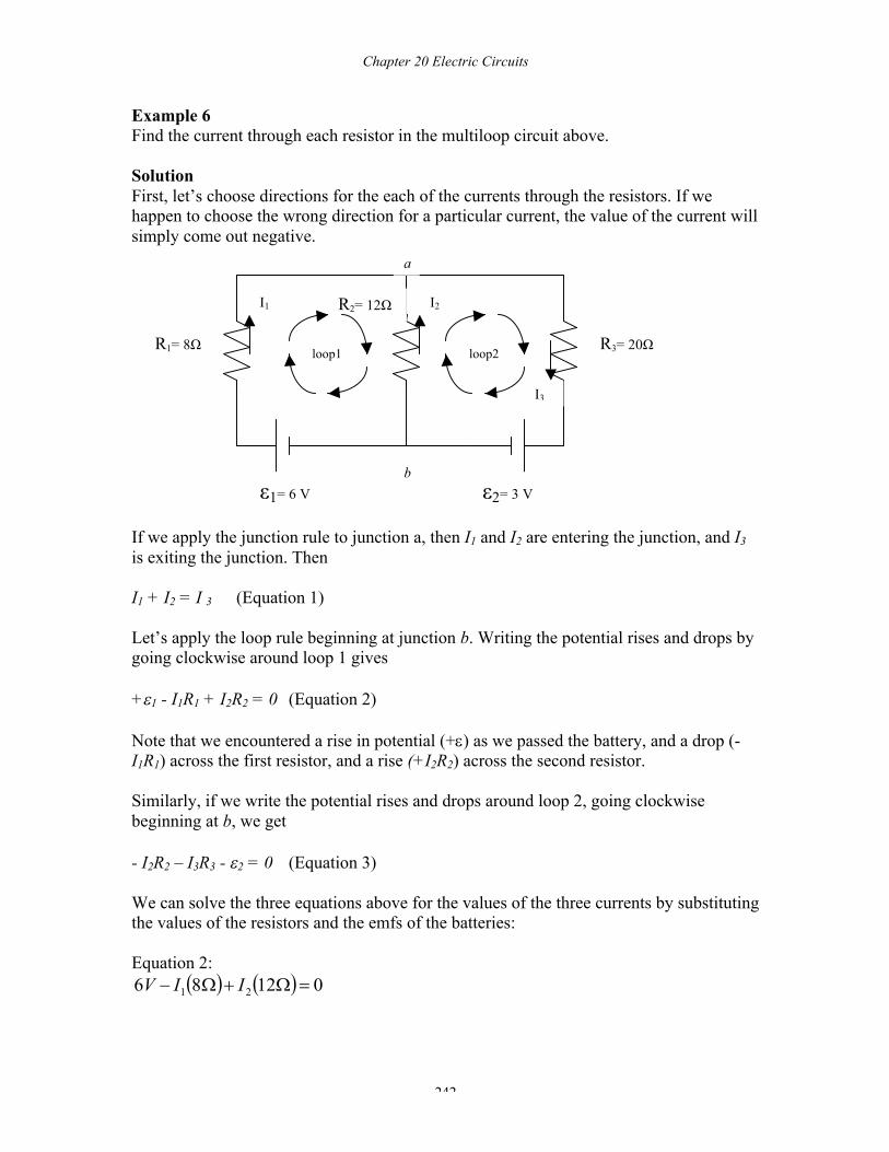
20.9 and 20.10 Internal Resistance and Kirchhoff’s Rules Consider the multi-loop circuit shown below:
In this circuit, we have three resistors and two batteries, one on either side of junction b. We can’t say that all the resistors are in series with each other, nor parallel, because of the placement of the batteries. If we want to find the current in and voltage across each resistor, we must use Kirchhoff’s rules. Kirchhoff’s Rules for Multi-loop Circuits: 1. The total current entering a junction (like a or b in the figure above) must also leave that junction. This is sometimes called the junction rule, and is a statement of conservation of charge. 2. The sum of the potential rises and drops (voltages) around a loop of a circuit must be zero. This is sometimes called the loop rule, and is a statement of conservation of energy. a. If we pass a battery from negative to positive, we say that there is a rise in
potential, +e. b. If we pass a battery from positive to negative, we say that there is a drop in potential, - e. c. If we pass a resistor against the direction of our arbitrarily chosen current, we say there is a rise in potential across the resistor, + IR. d. If we pass a resistor in the direction of our arbitrarily chosen current, we say there is a drop in potential across the resistor, - IR.
ε1= 6 V ε2= 3 V
R1= 8Ω R2= 12Ω R3= 20Ω
b
a
Chapter 20 Electric Circuits
242
Example 6 Find the current through each resistor in the multiloop circuit above. Solution First, let’s choose directions for the each of the currents through the resistors. If we happen to choose the wrong direction for a particular current, the value of the current will simply come out negative. If we apply the junction rule to junction a, then I1 and I2 are entering the junction, and I3 is exiting the junction. Then I1 + I2 = I 3 (Equation 1) Let’s apply the loop rule beginning at junction b. Writing the potential rises and drops by going clockwise around loop 1 gives +e1 - I1R1 + I2R2 = 0 (Equation 2) Note that we encountered a rise in potential (+e) as we passed the battery, and a drop (- I1R1) across the first resistor, and a rise (+I2R2) across the second resistor. Similarly, if we write the potential rises and drops around loop 2, going clockwise beginning at b, we get - I2R2 – I3R3 - e2 = 0 (Equation 3) We can solve the three equations above for the values of the three currents by substituting the values of the resistors and the emfs of the batteries: Equation 2:
( ) ( ) 01286 21 =W+W- IIV
ε1= 6 V ε2= 3 V
R1= 8Ω
R2= 12Ω
R3= 20Ω
b
a
loop1 loop2
I1 I2
I3
Chapter 20 Electric Circuits
243
Equation 3: ( ) ( ) 032012 32 =-W-W- VII
Solving Equations 1, 2, and 3 simultaneously gives I1 = - 6.3 A, I2 = 9.2 A, and I3 = 2.9 A. Note that I1 is negative, which simply means we chose the wrong direction for the current through R1. CHAPTER 20 REVIEW QUESTIONS For each of the multiple choice questions below, choose the best answer. Questions 1 – 3: Two resistors of 2 W and 4 W are placed in series with a 12-V battery. 1. Which of the following statements is true? (A) The 2W will get more current than
the 4 W resistor since it has less resistance.
(B) The 4 W will get more current than the 2 W resistor since it has more resistance.
(C) The 2 W and 4 W resistors will get the same voltage.
(D) The 2W resistor will get more voltage than the 4W resistor.
(E) The 4W resistor will get more voltage than the 2W resistor.
2. The current in the 2 W resistor is (A) 6 A (B) 4 A (C) 3 A (D) 2 A (E) 1 A 3. The voltage across the 4 W resistor is (A) 2 V
(B) 4 V (C) 6 V (D) 8 V (E) 12 V
Chapter 20 Electric Circuits
244
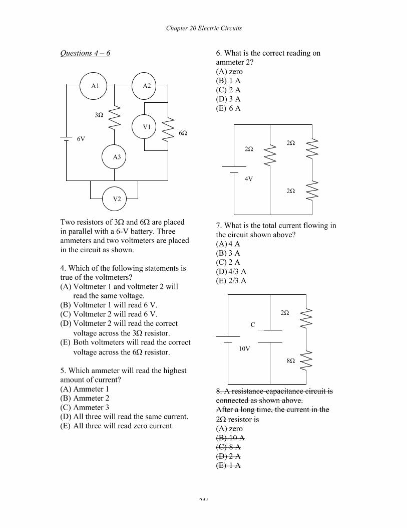
Questions 4 – 6
Two resistors of 3W and 6W are placed in parallel with a 6-V battery. Three ammeters and two voltmeters are placed in the circuit as shown. 4. Which of the following statements is true of the voltmeters? (A) Voltmeter 1 and voltmeter 2 will
read the same voltage. (B) Voltmeter 1 will read 6 V. (C) Voltmeter 2 will read 6 V. (D) Voltmeter 2 will read the correct
voltage across the 3W resistor. (E) Both voltmeters will read the correct
voltage across the 6W resistor. 5. Which ammeter will read the highest amount of current? (A) Ammeter 1 (B) Ammeter 2 (C) Ammeter 3 (D) All three will read the same current. (E) All three will read zero current.
6. What is the correct reading on ammeter 2? (A) zero (B) 1 A (C) 2 A (D) 3 A (E) 6 A
7. What is the total current flowing in the circuit shown above? (A) 4 A (B) 3 A (C) 2 A (D) 4/3 A (E) 2/3 A 8. A resistance-capacitance circuit is connected as shown above. After a long time, the current in the 2W resistor is (A) zero (B) 10 A (C) 8 A (D) 2 A (E) 1 A
A1 A2
A3
6Ω
3Ω
6V
V1
V2
4V
2Ω
2Ω
2Ω
10V
2Ω
8Ω
C
Chapter 20 Electric Circuits
245
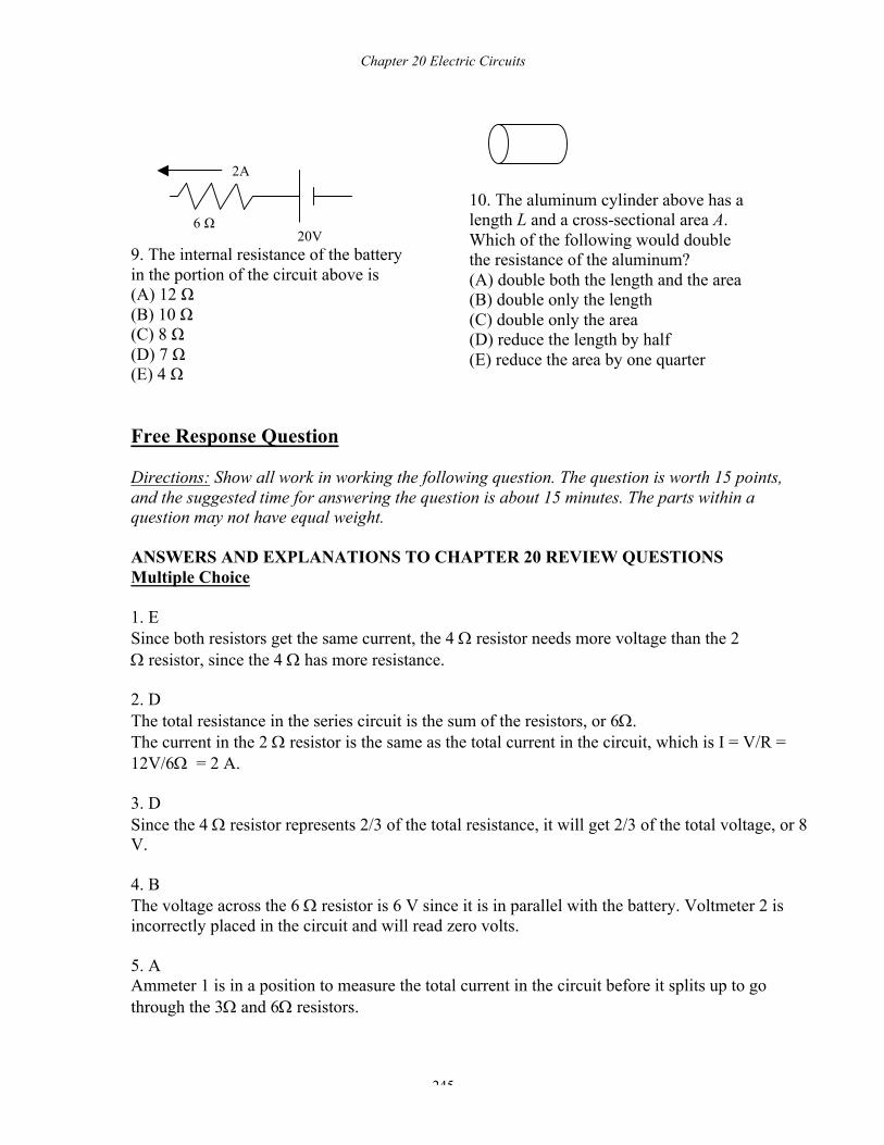
9. The internal resistance of the battery in the portion of the circuit above is (A) 12 Ω (B) 10 Ω (C) 8 Ω (D) 7 Ω (E) 4 Ω
10. The aluminum cylinder above has a length L and a cross-sectional area A. Which of the following would double the resistance of the aluminum? (A) double both the length and the area (B) double only the length (C) double only the area (D) reduce the length by half (E) reduce the area by one quarter
Free Response Question Directions: Show all work in working the following question. The question is worth 15 points, and the suggested time for answering the question is about 15 minutes. The parts within a question may not have equal weight. ANSWERS AND EXPLANATIONS TO CHAPTER 20 REVIEW QUESTIONS Multiple Choice 1. E Since both resistors get the same current, the 4 W resistor needs more voltage than the 2 W resistor, since the 4 W has more resistance. 2. D The total resistance in the series circuit is the sum of the resistors, or 6W. The current in the 2 W resistor is the same as the total current in the circuit, which is I = V/R = 12V/6W = 2 A. 3. D Since the 4 W resistor represents 2/3 of the total resistance, it will get 2/3 of the total voltage, or 8 V. 4. B The voltage across the 6 W resistor is 6 V since it is in parallel with the battery. Voltmeter 2 is incorrectly placed in the circuit and will read zero volts. 5. A Ammeter 1 is in a position to measure the total current in the circuit before it splits up to go through the 3W and 6W resistors.
6 Ω 20V
2A
Chapter 20 Electric Circuits
246
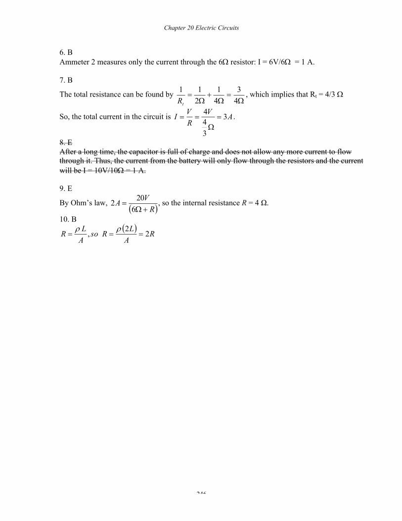
6. B Ammeter 2 measures only the current through the 6W resistor: I = 6V/6W = 1 A. 7. B
The total resistance can be found by W
=W
+W
=43
41
211
tR, which implies that Rt = 4/3 W
So, the total current in the circuit is AVRVI 3
344
=W
== .
8. E After a long time, the capacitor is full of charge and does not allow any more current to flow through it. Thus, the current from the battery will only flow through the resistors and the current will be I = 10V/10W = 1 A. 9. E
By Ohm’s law, ( )RVA+W
=6202 , so the internal resistance R = 4 Ω.
10. B ( ) RALRso
ALR 22, ===
rr