chapter 14: drip irrigation - fao.org · in drip irrigation, water is applied to each plant...
TRANSCRIPT
CHAPTER 14:Drip irrigation
INTRODUCTION
In drip irrigation, water is applied to each plant separately in small,frequent, precise quantities through dripper emitters. It is the mostadvanced irrigation method with the highest application efficiency. Thewater is delivered continuously in drops at the same point and moves intothe soil and wets the root zone vertically by gravity and laterally bycapillary action. The planted area is only partially wetted.
In medium-heavy soils of good structure, the lateral movement of thewater beneath the surface is greater than in sandy soils (Table 14.1).Moreover, when the discharge rate of the dripper exceeds the soil intakerate and hydraulic conductivity, the water ponds on the surface. Thisresults in the moisture being distributed more laterally rather thanvertically. The following water lateral spread values are indicative:
SYSTEM LAYOUT AND COMPONENTS
A complete drip irrigation system consists of a head control unit, main andsubmain pipelines, hydrants, manifolds and lateral lines with dripper emitters.
Control station (head control unit)
Its features and equipment depend on the system’s requirements.Usually, it consists of the shut-off, air and check (non-return) valves, afiltering unit, a fertilizer injector and other smaller accessories.
Main and submain pipelines:
The main and submain pipelines are usually buried, especially whenmade of rigid PVC.
Pressurized Irrigation TechniquesPressurized Irrigation Techniques 14.1
Type of soil
Light textureMedium textureFine texture
Average radius of water spread
0.30 m0.65 m1.20 m
TABLE 14.1 - Type of soil and average radius of water spread laterally with drippers

Hydrants
Fitted on the mains or the submains and equipped with 2–3 inches shut-off valves, they are capable of delivering all or part of the piped water flowto the manifold feeder lines. They are placed in valve boxes for protection.
Manifold (feeder) pipelines
These are usually 50, 63 or 75 mm. Where made of HDPE, they areattached to the hydrants through compression-type, quick release, PPconnector fittings and remain on the surface.
Dripper laterals
These are always made of 12–20 mm soft black LDPE, PN 3.0–4.0 bars.They are fitted to the manifolds with small PP connector fittings at fixedpositions and laid along the plant rows. They are equipped with closelyspaced dripper emitters or emission outlets (Figure 14.1).
In general, the distribution network (mains, submains and manifolds)consists of thermoplastic pipes and fittings (PVC, PE, PP, etc.), PN 6.0 and10.0 bars. However, for the mains, submains and manifolds, other kind ofpipes can also be used, such as quick coupling light steel pipes. In the past,permanently assembled buried rigid PVC pipes were used as mains and
Pressurized Irrigation TechniquesChapter 14 – Drip irrigation14.2
FIGURE 14.1 - The mains, manifold and dripper laterals.

submains, with hydrants rising on the surface at desired points. Morerecently, surface-laid 50–75 mm HDPE pipes, PN 6.0 bars, have been usedfor the whole distribution network in smallholdings. Larger diameter PEpipes are also available but cost more than rigid PVC pipes of the same size.
The system’s pressure ranges from 2.0 to 3.0 bars. Therefore, all dripirrigation systems can be classed as low pressure, localized, solidpermanent or seasonal installation systems.
DRIP EMITTERS (DRIPPERS)
The drippers are small-sized emitters made of high quality plastics. Theyare mounted on small soft PE pipes (hoses) at frequent spaces. Water entersthe dripper emitters at approximately 1.0 bar and is delivered at zeropressure in the form of continuous droplets at low rates of 1.0–24 litres/h.Drippers are divided into two main groups according to the way theydissipate energy (pressure):
• orifice type, with tiny flow areas of 0.2–0.35 mm2;• long-path type, with relatively larger flow areas of 1–4.5 mm2.
Both types are manufactured with various mechanisms and principles ofoperation, such as a vortex diode, a diaphragm or a floating disc for theorifice drippers, and a labyrinthine path, of various shapes, for the long-pathones. All the drippers now available on the market are turbulent flow ones.
Drippers are also characterized by the type of connection to the lateral:on-line, i.e. inserted in the pipe wall by the aid of a punch; or in-line,where the pipe is cut to insert the dripper manually or with a machine.
On-line multi-exit drippers are also available with four to six ‘spaghetti’type tube outlets.
Specifications that should be stated by the supplier are:
• dripper discharge (flow rate) at the recommended operating pressure,usually 1.0 bar;
• dripper discharge versus pressure variations and the optimum lengthof dripper line with different spacing and slopes;
• type of connection;• filtration requirements;• coefficient of variation (cv) (the drippers’ manufacturing variability).
Dripper emitters which are available as separate items, not built into thepipe, can be referred to as separate source point drippers.
Pressurized Irrigation TechniquesPressurized Irrigation Techniques 14.3

Pressurized Irrigation TechniquesChapter 14 – Drip irrigation14.4
DRIP TAPES
These are thin-walled integral drip lines with emission points spaced10, 20, 30, 45 cm or any other distance apart, delivering lower quantitiesof water than the usual drippers at very low pressures, i.e. 0.4–1.0 litres/hat 0.6–1.0 bar. They are integrated drip lines where the drippers are built inthe pipe walls at the desired spacing during the manufacturing process.They are ready-made dripper laterals with a very high uniformity ofapplication. Drip tapes are made of LDPE or other soft PE materials invarious diameters from 12 to 20 mm and in several wall thicknesses(0.10–1.25 mm). Thanks to a filtration system incorporated inside thetubing, they are less susceptible to mechanical and biological blockagesthan conventional drippers are.
POROUS-WALL PIPES
These pipes are small-sized (about 16 mm) thin-walled porous flexiblehoses made from PE fibres, PVC, ABS or rubber. They permit water andnutrients under low pressure to pass from inside the tube, by transpiration,and irrigate the crops. The porous pipeline discharge is not accuratebecause the size of the pores varies and is not stable. They are used aslateral drip lines beneath the surface. Their application is limited althoughthey do offer some advantages.
FILTRATION
The filtration of the irrigation water is of major importance for thenormal application of this system. The solid content in the water must beremoved through effective filtration in order to avoid blockage damage inthe drippers. The kind of filtration depends on the impurities contained inthe water and the degree of filtration required.
IRRIGATION SCHEDULING
In drip irrigation, the soil volume in the root zone is only partly wettedand the availability of moisture restricted. The soil moisture depletionshould not exceed 40 percent of the soil available moisture in the lategrowing stages of vegetables and fruit trees, and 20–30 percent in the earlystages for vegetables. However, in order to obtain higher yields, thecommon practice is to irrigate every day in the later stages. Properirrigation scheduling can be arranged by using tensiometers to indicate thesoil moisture tension in the root zone. This should range from 10 cbars forlight soils to 25 cbars for heavy soils.
DESIGN CRITERIA AND CONSIDERATIONS
Drip irrigation is mainly applied in intensive cultivations planted in rows(vegetables, fruit trees, melons, bananas, papayas, flowers, grapes, etc.). It isnot recommended for potatoes, salad leafy vegetables, groundnuts, alfalfaand other dense planted crops, although it can be applied successfully.
The drippers and/or the lateral spacing are directly related to the cropplanting spacing. In most vegetable crops, the dripper spacing is identicalto the crop planting spacing, i.e. one dripper per plant and one dripperlateral per row of cultivation. With drip tapes there are several emissionpoints per plant in order to ensure a continuous wetted strip along the row.Here, the arrangement is one drip tape per row of crop.
Under drip irrigation, most of the vegetables develop the bulk of their rootsin the first 30 cm depth of the soil profile below the emission point. Thus, ifboth the crop and the emission points along the rows are closely spaced, mostof the soil volume can be sufficiently wetted with optimum results.
Where the crop is planted closely in beds, one dripper lateral per tworows might be applied with good results. Other crops planted in doublerows (celery, capsicum and hot peppers) are also irrigated by one dripperlateral placed in between the rows.
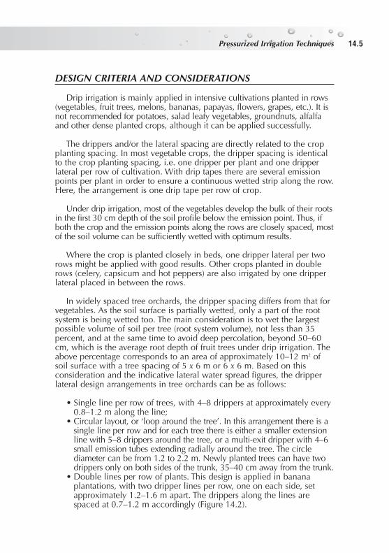
In widely spaced tree orchards, the dripper spacing differs from that forvegetables. As the soil surface is partially wetted, only a part of the rootsystem is being wetted too. The main consideration is to wet the largestpossible volume of soil per tree (root system volume), not less than 35percent, and at the same time to avoid deep percolation, beyond 50–60cm, which is the average root depth of fruit trees under drip irrigation. Theabove percentage corresponds to an area of approximately 10–12 m2 ofsoil surface with a tree spacing of 5 x 6 m or 6 x 6 m. Based on thisconsideration and the indicative lateral water spread figures, the dripperlateral design arrangements in tree orchards can be as follows:
• Single line per row of trees, with 4–8 drippers at approximately every0.8–1.2 m along the line;
• Circular layout, or ‘loop around the tree’. In this arrangement there is asingle line per row and for each tree there is either a smaller extensionline with 5–8 drippers around the tree, or a multi-exit dripper with 4–6small emission tubes extending radially around the tree. The circlediameter can be from 1.2 to 2.2 m. Newly planted trees can have twodrippers only on both sides of the trunk, 35–40 cm away from the trunk.
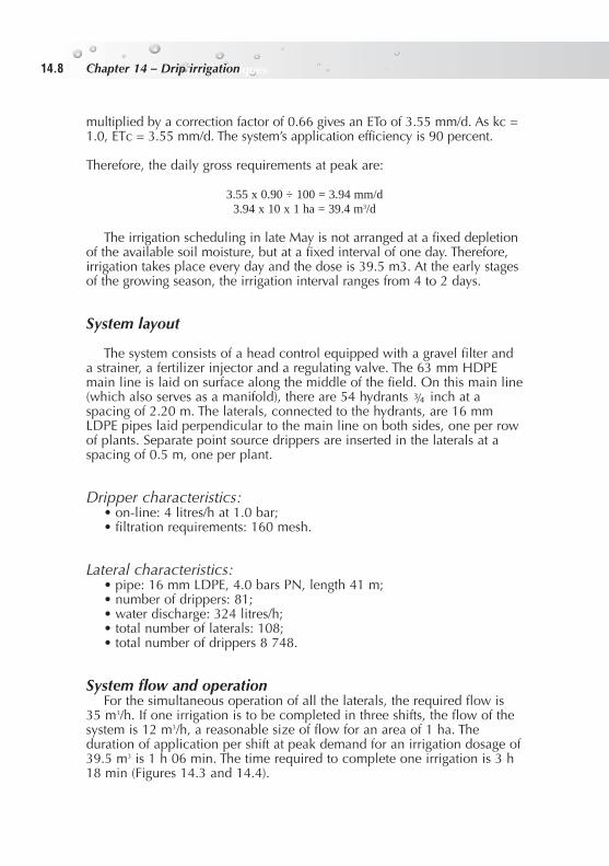
• Double lines per row of plants. This design is applied in bananaplantations, with two dripper lines per row, one on each side, setapproximately 1.2–1.6 m apart. The drippers along the lines arespaced at 0.7–1.2 m accordingly (Figure 14.2).
Pressurized Irrigation TechniquesPressurized Irrigation Techniques 14.5

Pressurized Irrigation TechniquesChapter 14 – Drip irrigation14.6
COST
The cost for a complete drip irrigation installation is US$4 000–5 000/ha.The cost of the pipes (all tubing, laterals included) is about US$2 000, i.e.45 percent of the total cost. The head control unit accounts for 30 percent ofthe total cost.
ADVANTAGES
• Water savings. The planted area is partially wetted with preciselycontrolled water amounts. Thus, large quantities of irrigation waterare saved and the irrigated area can be expanded with the samewater supply, resulting in higher income per unit of water.
• Utilization of saline water resources. With drip irrigation, low soilmoisture tensions in the root zone can be maintained continuouslywith frequent applications. The dissolved salts accumulate at theperiphery of the wetted soil mass, and the plants can easily obtain themoisture needed. This enables the use of saline water containingmore than 3 000 mg/litre TDS, which would be unsuitable for usewith other methods.
FIGURE 14.2 - Double lines with bananas.

• Use on marginal fields. Small irregular marginal plots, remote becauseof land fragmentation with varying topography and shallow soil full ofrocks, can be productive under drip irrigation techniques that deliverthe required amounts of water and nutrients directly to the plants.
• Low labour operating requirements, reduced cultivation and weedcontrol, and uninterrupted operation are among the other advantagesof this irrigation method.
DISADVANTAGES
• High initial purchase cost.• Good irrigation management is essential for skilled system operation,
application of fertigation and maintenance of the head control unitequipment (filters, injectors, etc.).
• Emitter blockages. The first limitation on the successful introduction ofdrip irrigation techniques in developing countries is mechanicalclogging of the emitters because of insufficient filtration of impuritiesin the irrigation water.
EXAMPLE DESIGN – Drip irrigation in watermelons
Area and crop
The plot dimensions are 120 x 83 m (about 1 ha), planted in the openwith watermelons in rows 2.20 m apart and spaced along the rows at 0.5m. The plot is divided into two parts, each with 54 rows 40.5 m long.There are 81 plants per row. Thus, there are 4 374 plants in each part, i.e.8 748 plants in the whole plot and 108 plant rows.
Soil, water and climate
Heavy texture soil with low permeability (approximately 6 mm/h) and ahigh water holding capacity. The source of water is a nearby open waterreservoir; it is of good quality but with a high impurity content of organicorigin (algae). The crop growing season is from early April to early July; theevaporation pan average maximum readings are 3.3 mm/d in April, 4.64mm/d in May and 6.13 mm/d in June.
Crop water requirements and irrigation schedule
The maximum irrigation requirements of the watermelons are during themid-season stage and the yield formation in late May-early June, when thekc value is 1.0. The average reading for the two months is 5.38 mm/d, which
Pressurized Irrigation TechniquesPressurized Irrigation Techniques 14.7
Pressurized Irrigation TechniquesChapter 14 – Drip irrigation14.8
multiplied by a correction factor of 0.66 gives an ETo of 3.55 mm/d. As kc =1.0, ETc = 3.55 mm/d. The system’s application efficiency is 90 percent.
Therefore, the daily gross requirements at peak are:
3.55 x 0.90 ÷ 100 = 3.94 mm/d3.94 x 10 x 1 ha = 39.4 m3/d
The irrigation scheduling in late May is not arranged at a fixed depletionof the available soil moisture, but at a fixed interval of one day. Therefore,irrigation takes place every day and the dose is 39.5 m3. At the early stagesof the growing season, the irrigation interval ranges from 4 to 2 days.
System layout
The system consists of a head control equipped with a gravel filter anda strainer, a fertilizer injector and a regulating valve. The 63 mm HDPEmain line is laid on surface along the middle of the field. On this main line(which also serves as a manifold), there are 54 hydrants inch at aspacing of 2.20 m. The laterals, connected to the hydrants, are 16 mmLDPE pipes laid perpendicular to the main line on both sides, one per rowof plants. Separate point source drippers are inserted in the laterals at aspacing of 0.5 m, one per plant.
Dripper characteristics:• on-line: 4 litres/h at 1.0 bar;• filtration requirements: 160 mesh.
Lateral characteristics:• pipe: 16 mm LDPE, 4.0 bars PN, length 41 m;• number of drippers: 81;• water discharge: 324 litres/h;• total number of laterals: 108;• total number of drippers 8 748.
System flow and operationFor the simultaneous operation of all the laterals, the required flow is
35 m3/h. If one irrigation is to be completed in three shifts, the flow of thesystem is 12 m3/h, a reasonable size of flow for an area of 1 ha. Theduration of application per shift at peak demand for an irrigation dosage of39.5 m3 is 1 h 06 min. The time required to complete one irrigation is 3 h18 min (Figures 14.3 and 14.4).