chapter 12 8085 interrupts -...
TRANSCRIPT

Mohd. Moinul Hoque, Lecturer, CSE, AUST
CSE 307 - Microprocessors 1
Chapter 12
8085 Interrupts
Mohd. Moinul Hoque, Lecturer, CSE, AUST
CSE 307 - Microprocessors 2
Interrupts
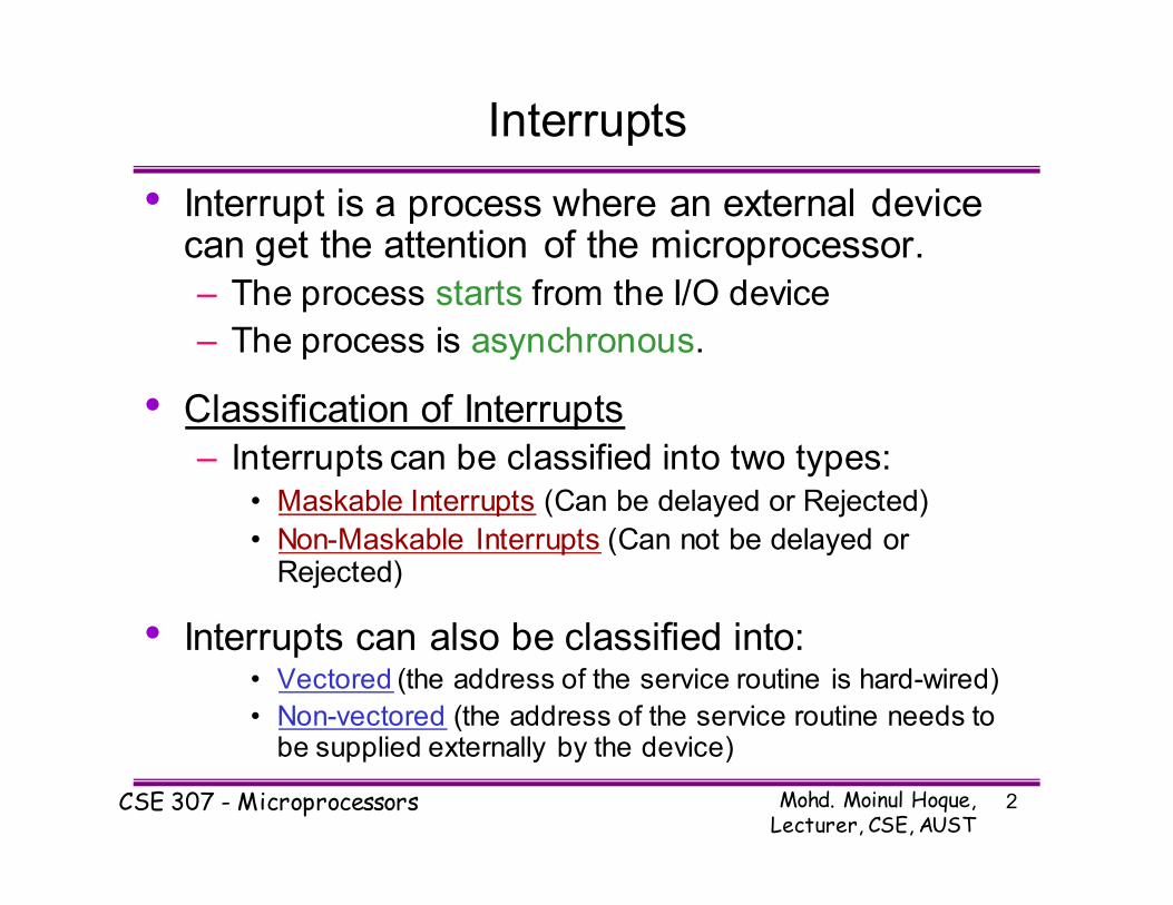
• Interrupt is a process where an external device can get the attention of the microprocessor.
– The process starts from the I/O device
– The process is asynchronous.
• Classification of Interrupts
– Interrupts can be classified into two types:• Maskable Interrupts (Can be delayed or Rejected)
• Non-Maskable Interrupts (Can not be delayed or Rejected)
• Interrupts can also be classified into:• Vectored (the address of the service routine is hard-wired)
• Non-vectored (the address of the service routine needs to be supplied externally by the device)
Mohd. Moinul Hoque, Lecturer, CSE, AUST
CSE 307 - Microprocessors 3
Interrupts
• An interrupt is considered to be an emergency
signal that may be serviced.
– The Microprocessor may respond to it as soon as possible.
• What happens when MP is interrupted ?
– When the Microprocessor receives an interrupt
signal, it suspends the currently executing program and jumps to an Interrupt Service
Routine (ISR) to respond to the incoming interrupt.
– Each interrupt will most probably have its own
ISR.
Mohd. Moinul Hoque, Lecturer, CSE, AUST
CSE 307 - Microprocessors 4
Responding to Interrupts
• Responding to an interrupt may be immediate or
delayed depending on whether the interrupt is
maskable or non-maskable and whether
interrupts are being masked or not.
• There are two ways of redirecting the execution
to the ISR depending on whether the interrupt is
vectored or non-vectored.
– Vectored: The address of the subroutine is already
known to the Microprocessor
– Non Vectored: The device will have to supply the address of the subroutine to the Microprocessor

Mohd. Moinul Hoque, Lecturer, CSE, AUST
CSE 307 - Microprocessors 5
The 8085 Interrupts
• When a device interrupts, it actually wants the
MP to give a service which is equivalent to
asking the MP to call a subroutine. This
subroutine is called ISR (Interrupt Service
Routine)
• The ‘EI’ instruction is a one byte instruction and
is used to Enable the non-maskable interrupts.
• The ‘DI’ instruction is a one byte instruction and
is used to Disable the non-maskable interrupts.
• The 8085 has a single Non-Maskable interrupt.
– The non-maskable interrupt is not affected by the
value of the Interrupt Enable flip flop.

Mohd. Moinul Hoque, Lecturer, CSE, AUST
CSE 307 - Microprocessors 6
The 8085 Interrupts
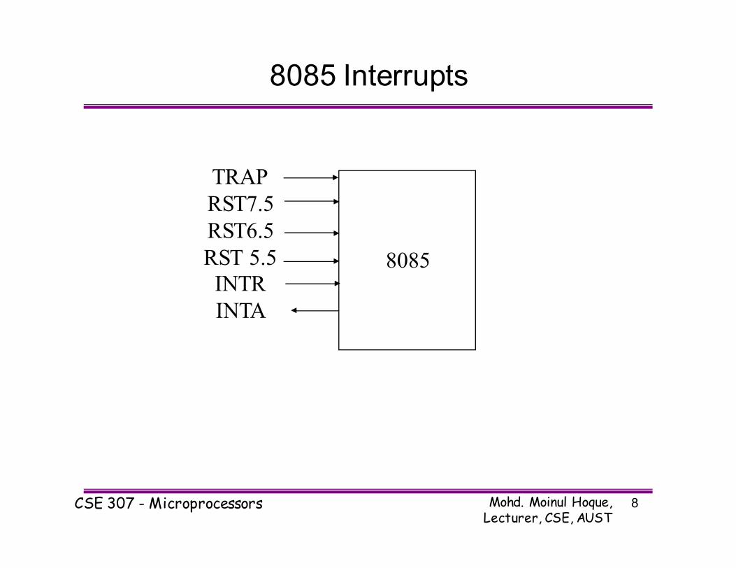
• The 8085 has 5 interrupt inputs.
– The INTR input.
• The INTR input is the only non-vectored interrupt.
• INTR is maskable using the EI/DI instruction pair.
– RST 5.5, RST 6.5, RST 7.5 are all automatically
vectored.
• RST 5.5, RST 6.5, and RST 7.5 are all maskable.
– TRAP is the only non-maskable interrupt in the
8085
• TRAP is also automatically vectored

Mohd. Moinul Hoque, Lecturer, CSE, AUST
CSE 307 - Microprocessors 7
The 8085 Interrupts
Interrupt name Maskable Vectored
INTR Yes No
RST 5.5 Yes Yes
RST 6.5 Yes Yes
RST 7.5 Yes Yes
TRAP No Yes
Mohd. Moinul Hoque, Lecturer, CSE, AUST
CSE 307 - Microprocessors 8
8085 Interrupts
8085
TRAP
RST7.5
RST6.5
RST 5.5
INTR
INTA
Mohd. Moinul Hoque, Lecturer, CSE, AUST
CSE 307 - Microprocessors 9
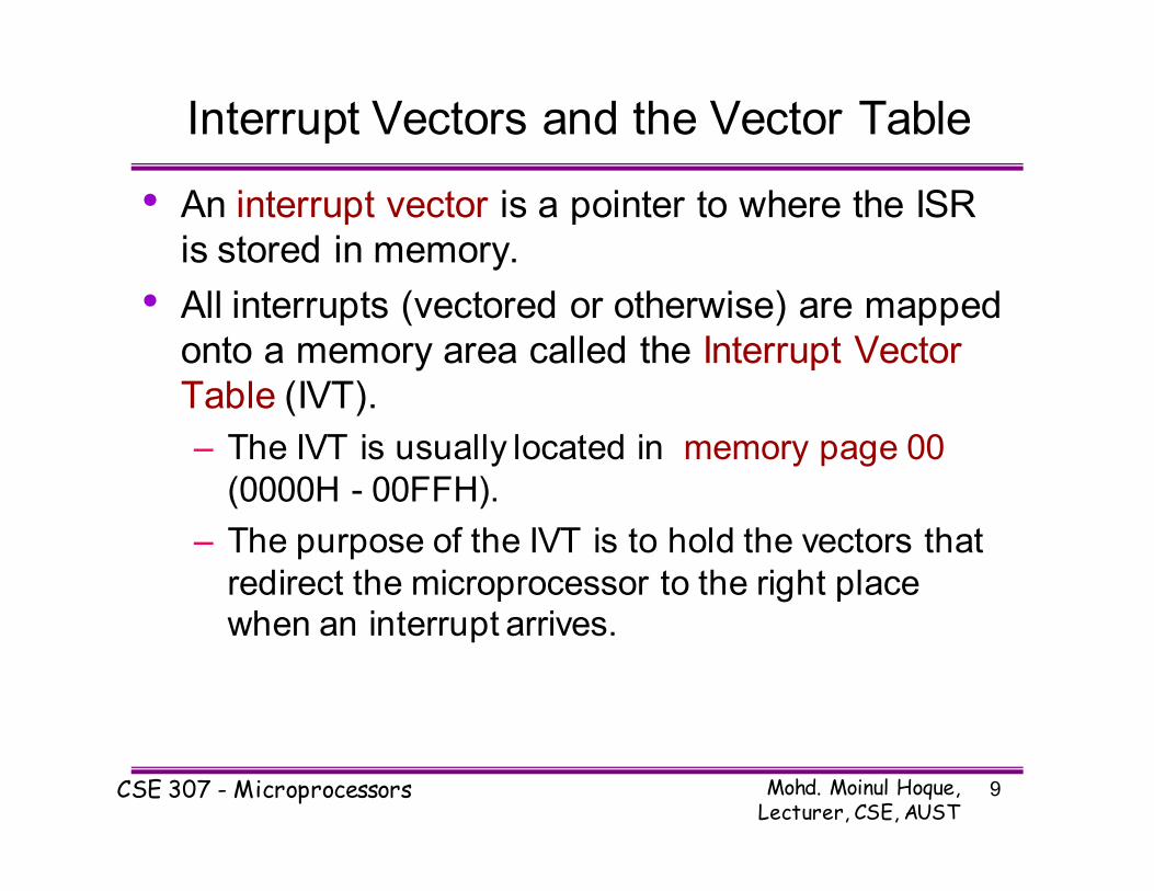
Interrupt Vectors and the Vector Table
• An interrupt vector is a pointer to where the ISR
is stored in memory.
• All interrupts (vectored or otherwise) are mapped
onto a memory area called the Interrupt Vector
Table (IVT).
– The IVT is usually located in memory page 00
(0000H - 00FFH).
– The purpose of the IVT is to hold the vectors that
redirect the microprocessor to the right place when an interrupt arrives.

Mohd. Moinul Hoque, Lecturer, CSE, AUST
CSE 307 - Microprocessors 10
• Example: Let , a device interrupts the
Microprocessor using the RST 7.5 interrupt line.
– Because the RST 7.5 interrupt is vectored, Microprocessor knows , in which memory location
it has to go using a call instruction to get the ISR
address. RST7.5 is knows as Call 003Ch to
Microprocessor. Microprocessor goes to 003C
location and will get a JMP instruction to the actual ISR address. The Microprocessor will then, jump
to the ISR location
– The process is illustrated in the next slide..

Mohd. Moinul Hoque, Lecturer, CSE, AUST
CSE 307 - Microprocessors 11
This slide is available in the printed copy

Mohd. Moinul Hoque, Lecturer, CSE, AUST
CSE 307 - Microprocessors 12
1. The interrupt process should be enabled using the EI
instruction.
2. The 8085 checks for an interrupt during the execution of
every instruction.
3. If INTR is high, MP completes current instruction, disables
the interrupt and sends INTA (Interrupt acknowledge) signal
to the device that interrupted
4. INTA allows the I/O device to send a RST instruction
through data bus.
5. Upon receiving the INTA signal, MP saves the memory
location of the next instruction on the stack and the program
is transferred to ‘call’ location (ISR Call) specified by the
RST instruction
The 8085 Non-Vectored Interrupt Process

Mohd. Moinul Hoque, Lecturer, CSE, AUST
CSE 307 - Microprocessors 13
6. Microprocessor Performs the ISR.
7. ISR must include the ‘EI’ instruction to enable the
further interrupt within the program.
8. RET instruction at the end of the ISR allows the
MP to retrieve the return address from the stack
and the program is transferred back to where the
program was interrupted.
** See the example of the Class that showed how
interrupt process works for this 8 steps **
The 8085 Non-Vectored Interrupt Process

Mohd. Moinul Hoque, Lecturer, CSE, AUST
CSE 307 - Microprocessors 14
The 8085 Non-Vectored Interrupt Process
• The 8085 recognizes 8 RESTART instructions:
RST0 - RST7.
– each of these would send the execution to a predetermined hard-wired memory location:
Restart
Instruction
Equivalent
to
RST0 CALL 0000H
RST1 CALL 0008H
RST2 CALL 0010H
RST3 CALL 0018H
RST4 CALL 0020H
RST5 CALL 0028H
RST6 CALL 0030H
RST7 CALL 0038H

Mohd. Moinul Hoque, Lecturer, CSE, AUST
CSE 307 - Microprocessors 15
Restart Sequence
• The restart sequence is made up of three
machine cycles
– In the 1st machine cycle:
• The microprocessor sends the INTA signal.
• While INTA is active the microprocessor reads the data
lines expecting to receive, from the interrupting device,
the opcode for the specific RST instruction.
– In the 2nd and 3rd machine cycles:
• the 16-bit address of the next instruction is saved on the
stack.
• Then the microprocessor jumps to the address
associated with the specified RST instruction.

Mohd. Moinul Hoque, Lecturer, CSE, AUST
CSE 307 - Microprocessors 16
Timing Diagram of Restart Sequence
• See the Page 380, Figure 12.2, of your Text
Book for the Timing Diagram of the RST
instruction

Mohd. Moinul Hoque, Lecturer, CSE, AUST
CSE 307 - Microprocessors 17
Hardware Generation of RST Opcode
• How does the external device produce the
opcode for the appropriate RST instruction?
– The opcode is simply a collection of bits.
– So, the device needs to set the bits of the data bus
to the appropriate value in response to an INTA
signal.

Mohd. Moinul Hoque, Lecturer, CSE, AUST
CSE 307 - Microprocessors 18
The following is an
example of generating
RST 5:
RST 5’s opcode is EF =
D D
76543210
11101111
Hardware Generation of RST Opcode
Mohd. Moinul Hoque, Lecturer, CSE, AUST
CSE 307 - Microprocessors 19
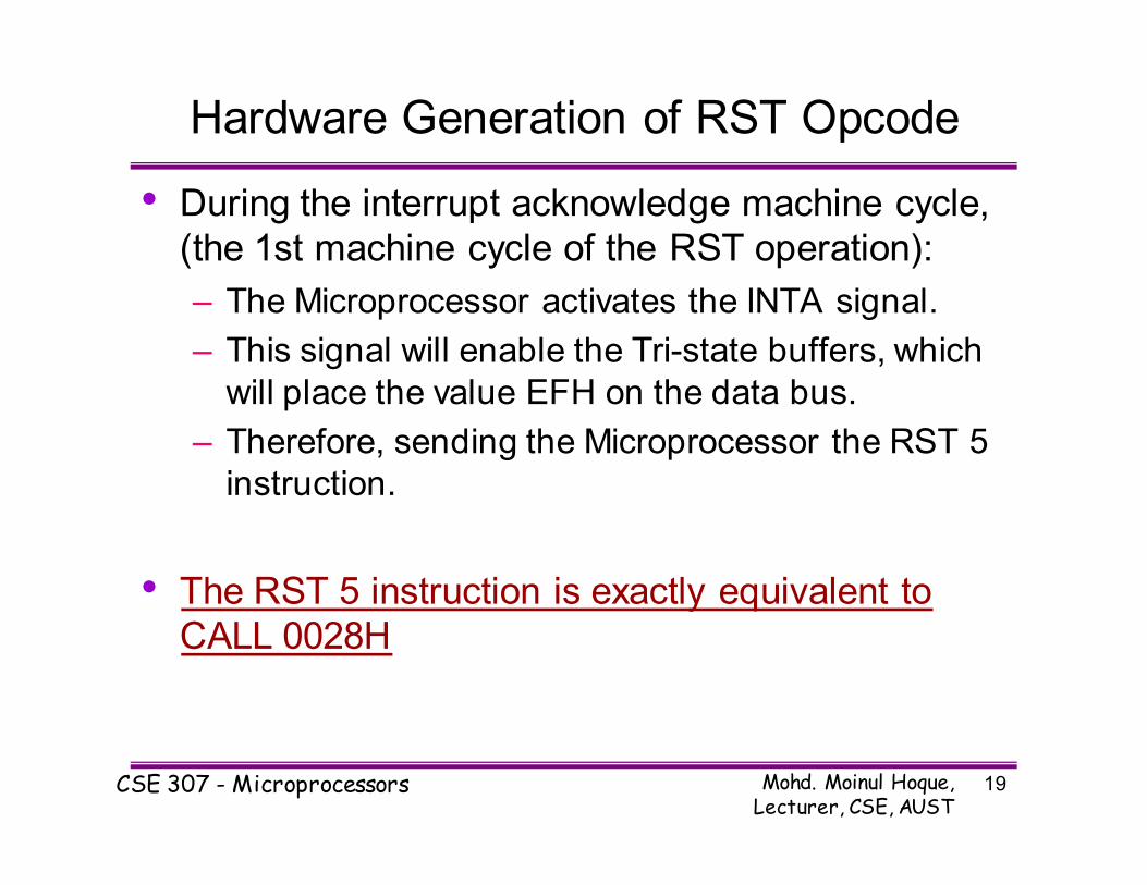
Hardware Generation of RST Opcode
• During the interrupt acknowledge machine cycle,
(the 1st machine cycle of the RST operation):
– The Microprocessor activates the INTA signal.
– This signal will enable the Tri-state buffers, which
will place the value EFH on the data bus.
– Therefore, sending the Microprocessor the RST 5
instruction.
• The RST 5 instruction is exactly equivalent to
CALL 0028H

Mohd. Moinul Hoque, Lecturer, CSE, AUST
CSE 307 - Microprocessors 20
Issues in Implementing INTR Interrupts
• How long must INTR remain high?
– The microprocessor checks the INTR line one clock cycle
before the last T-state of each instruction.
– The INTR must remain active long enough to allow for the
longest instruction.
– The longest instruction for the 8085 is the conditional CALL
instruction which requires 18 T-states.
• Therefore, the INTR must remain active for 17.5 T-
states.
• If f= 3MHZ then T=1/f and so, INTR must remain active
for [ (1/3MHZ) * 17.5 ≈ 5.8 micro seconds].

Mohd. Moinul Hoque, Lecturer, CSE, AUST
CSE 307 - Microprocessors 21
Issues in Implementing INTR Interrupts
• How long can the INTR remain high?
– The INTR line must be deactivated before the EI is
executed. Otherwise, the microprocessor will be
interrupted again.
– Once the microprocessor starts to respond to an
INTR interrupt, INTA becomes active (=0).
Therefore, INTR should be turned off as soon as
the INTA signal is received.
Mohd. Moinul Hoque, Lecturer, CSE, AUST
CSE 307 - Microprocessors 22
Issues in Implementing INTR Interrupts
• Can the microprocessor be interrupted again
before the completion of the ISR?
– As soon as the 1st interrupt arrives, all maskable interrupts are disabled.
– They will only be enabled after the execution of
the EI instruction.
Therefore, the answer is: “only if we allow it to”.
If the EI instruction is placed early in the ISR, other
interrupt may occur before the ISR is done.
Mohd. Moinul Hoque, Lecturer, CSE, AUST
CSE 307 - Microprocessors 23
Multiple Interrupts & Priorities
• How do we allow multiple devices to interrupt
using the INTR line?
– The microprocessor can only respond to one signal on INTR at a time.
– Therefore, we must allow the signal from only one
of the devices to reach the microprocessor.
– We must assign some priority to the different
devices and allow their signals to reach the
microprocessor according to the priority.

Mohd. Moinul Hoque, Lecturer, CSE, AUST
CSE 307 - Microprocessors 24
The Priority Encoder
• The solution is to use a circuit called the priority
encoder (74LS148).
– This circuit has 8 inputs and 3 outputs.
– The inputs are assigned increasing priorities
according to the increasing index of the input.
• Input 7 has highest priority and input 0 has the lowest.
– The 3 outputs carry the index of the highest
priority active input.
– Figure 12.4 in the book shows how this circuit can be used with a Tri-state buffer to implement an
interrupt priority scheme.

Mohd. Moinul Hoque, Lecturer, CSE, AUST
CSE 307 - Microprocessors 25
Multiple Interrupts & Priorities
• Note that the opcodes for the different RST
instructions follow a set pattern.
• Bit D5, D4 and D3 of the opcodes change in a binary
sequence from RST 7 down to RST 0.
• The other bits are always 1.
• This allows the code generated by the 74366 to be used
directly to choose the appropriate RST instruction.
• The one draw back to this scheme is that the
only way to change the priority of the devices
connected to the 74366 is to reconnect the
hardware.
Mohd. Moinul Hoque, Lecturer, CSE, AUST
CSE 307 - Microprocessors 26
Multiple Interrupts and Priority
See the Text Book, Page 384-385
for the detailed explanation of the
Multiple interrupt process

Mohd. Moinul Hoque, Lecturer, CSE, AUST
CSE 307 - Microprocessors 27
The 8085 Maskable/Vectored Interrupts
• The 8085 has 4 Masked/Vectored interrupt
inputs.
– RST 5.5, RST 6.5, RST 7.5
• They are all maskable.
• They are automatically vectored according to the
following table:
– The vectors for these interrupt fall in between the vectors
for the RST instructions. That’s why they have names like
RST 5.5 (RST 5 and a half).
Interrupt Vector
RST 5.5 002CH
RST 6.5 0034H
RST 7.5 003CH

Mohd. Moinul Hoque, Lecturer, CSE, AUST
CSE 307 - Microprocessors 28
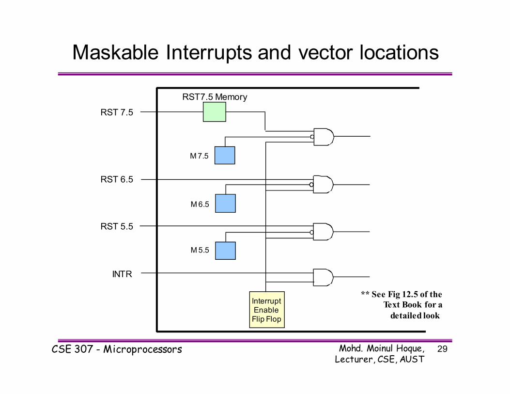
Masking RST 5.5, RST 6.5 and RST 7.5
• These three interrupts are masked at two levels:
– Through the Interrupt Enable flip flop and the EI/DI
instructions.
• The Interrupt Enable flip flop controls the whole
maskable interrupt process.
– Through individual mask flip flops that control the
availability of the individual interrupts.
• These flip flops control the interrupts individually.
Mohd. Moinul Hoque, Lecturer, CSE, AUST
CSE 307 - Microprocessors 29
Maskable Interrupts and vector locations
InterruptEnableFlip Flop
INTR
RST 5.5
RST 6.5
RST 7.5
M 5.5
M 6.5
M 7.5
RST7.5 Memory
** See Fig 12.5 of the
Text Book for a
detailed look
Mohd. Moinul Hoque, Lecturer, CSE, AUST
CSE 307 - Microprocessors 30
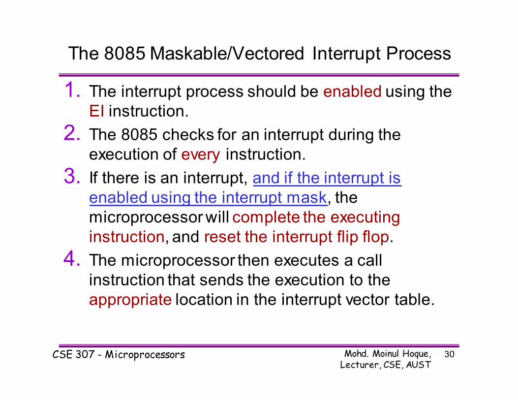
The 8085 Maskable/Vectored Interrupt Process
1. The interrupt process should be enabled using the
EI instruction.
2. The 8085 checks for an interrupt during the
execution of every instruction.
3. If there is an interrupt, and if the interrupt is
enabled using the interrupt mask, the
microprocessor will complete the executing
instruction, and reset the interrupt flip flop.
4. The microprocessor then executes a call
instruction that sends the execution to the
appropriate location in the interrupt vector table.

Mohd. Moinul Hoque, Lecturer, CSE, AUST
CSE 307 - Microprocessors 31
The 8085 Maskable/Vectored Interrupt Process
5. When the microprocessor executes the call
instruction, it saves the address of the next
instruction on the stack.
6. The microprocessor jumps to the specific service
routine.
7. The service routine must include the instruction EI
to re-enable the interrupt process.
8. At the end of the service routine, the RET
instruction returns the execution to where the
program was interrupted.

Mohd. Moinul Hoque, Lecturer, CSE, AUST
CSE 307 - Microprocessors 32
Manipulating the Masks
• The Interrupt Enable flip flop is manipulated
using the EI/DI instructions.
• The individual masks for RST 5.5, RST 6.5 and
RST 7.5 are manipulated using the SIM
instruction.
– This instruction takes the bit pattern in the
Accumulator and applies it to the interrupt mask enabling and disabling the specific interrupts.
Mohd. Moinul Hoque, Lecturer, CSE, AUST
CSE 307 - Microprocessors 33
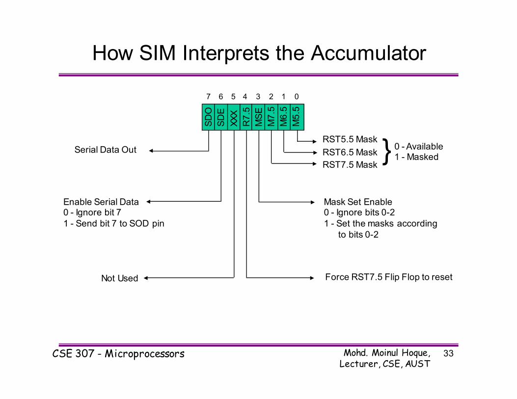
How SIM Interprets the Accumulator
SD
O
SD
E
XX
X
R7
.5
MS
E
M7
.5
M6
.5
M5
.5
01234567
RST5.5 Mask
RST6.5 Mask
RST7.5 Mask} 0 - Available
1 - Masked
Mask Set Enable0 - Ignore bits 0-2
1 - Set the masks according
to bits 0-2
Force RST7.5 Flip Flop to resetNot Used
Enable Serial Data0 - Ignore bit 7
1 - Send bit 7 to SOD pin
Serial Data Out
Mohd. Moinul Hoque, Lecturer, CSE, AUST
CSE 307 - Microprocessors 34
SIM and the Interrupt Mask
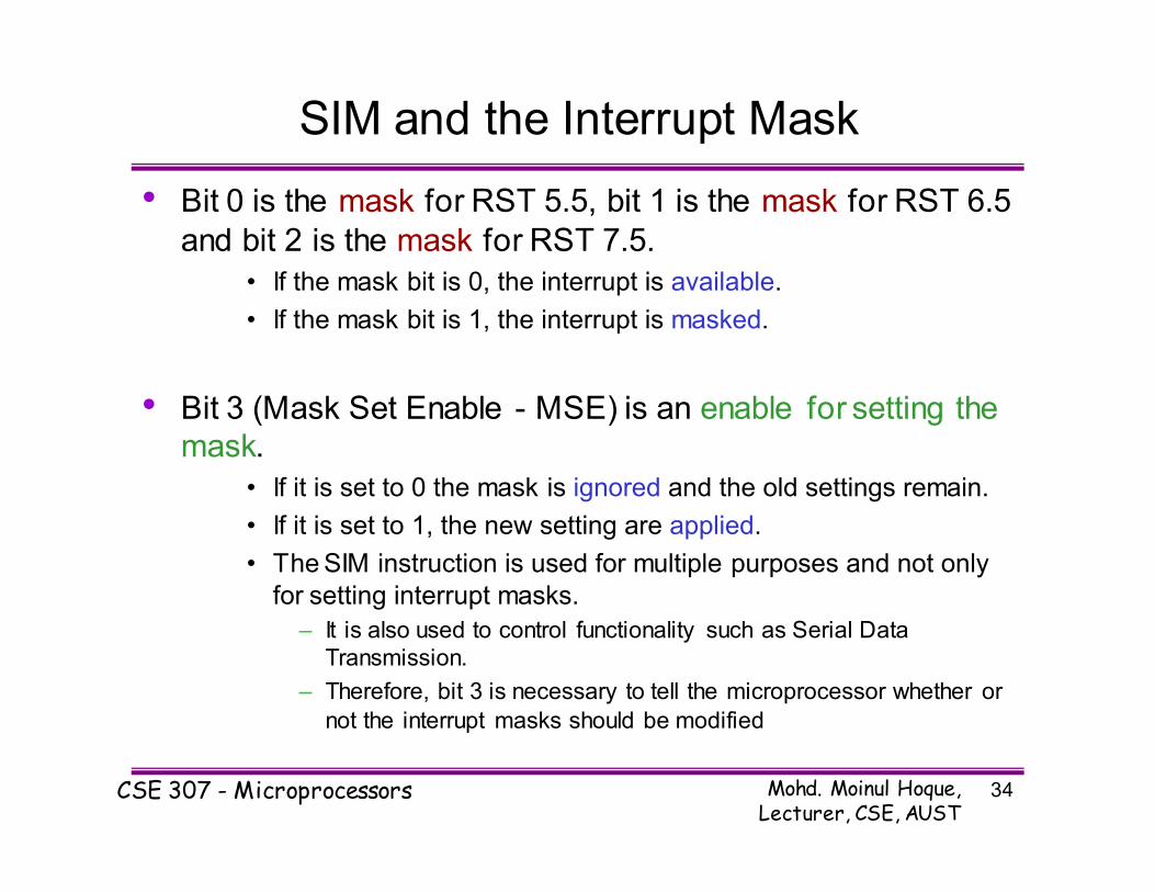
• Bit 0 is the mask for RST 5.5, bit 1 is the mask for RST 6.5
and bit 2 is the mask for RST 7.5.
• If the mask bit is 0, the interrupt is available.
• If the mask bit is 1, the interrupt is masked.
• Bit 3 (Mask Set Enable - MSE) is an enable for setting the
mask.
• If it is set to 0 the mask is ignored and the old settings remain.
• If it is set to 1, the new setting are applied.
• The SIM instruction is used for multiple purposes and not only
for setting interrupt masks.
– It is also used to control functionality such as Serial Data
Transmission.
– Therefore, bit 3 is necessary to tell the microprocessor whether or
not the interrupt masks should be modified

Mohd. Moinul Hoque, Lecturer, CSE, AUST
CSE 307 - Microprocessors 35
SIM and the Interrupt Mask
• The RST 7.5 interrupt is the only 8085 interrupt that has
memory.
– If a signal on RST7.5 arrives while it is masked, a flip flop will
remember the signal.
– When RST7.5 is unmasked, the microprocessor will be
interrupted even if the device has removed the interrupt
signal.
– This flip flop will be automatically reset when the
microprocessor responds to an RST 7.5 interrupt.
• Bit 4 of the accumulator in the SIM instruction allows
explicitly resetting the RST 7.5 memory even if the
microprocessor did not respond to it.
• Bit 5 is not used by the SIM instruction
Mohd. Moinul Hoque, Lecturer, CSE, AUST
CSE 307 - Microprocessors 36
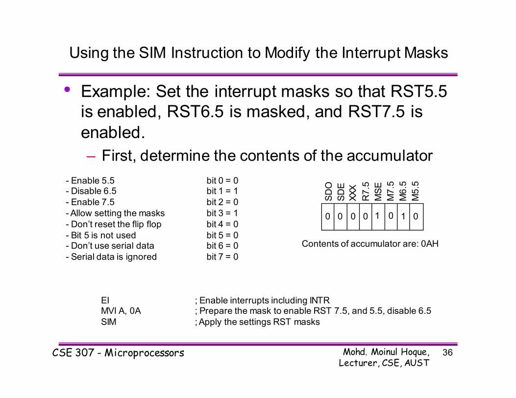
Using the SIM Instruction to Modify the Interrupt Masks
• Example: Set the interrupt masks so that RST5.5
is enabled, RST6.5 is masked, and RST7.5 is
enabled.
– First, determine the contents of the accumulator
SD
O
SD
E
XX
X
R7
.5
MS
E
M7
.5
M6
.5
M5
.5
- Enable 5.5 bit 0 = 0- Disable 6.5 bit 1 = 1
- Enable 7.5 bit 2 = 0
- Allow setting the masks bit 3 = 1
- Don’t reset the flip flop bit 4 = 0
- Bit 5 is not used bit 5 = 0- Don’t use serial data bit 6 = 0
- Serial data is ignored bit 7 = 0
0 1 00000 1
Contents of accumulator are: 0AH
EI ; Enable interrupts including INTRMVI A, 0A ; Prepare the mask to enable RST 7.5, and 5.5, disable 6.5
SIM ; Apply the settings RST masks
Mohd. Moinul Hoque, Lecturer, CSE, AUST
CSE 307 - Microprocessors 37
Triggering Levels
• RST 7.5 is positive edge sensitive.• When a positive edge appears on the RST7.5 line, a
logic 1 is stored in the flip-flop as a “pending” interrupt.
• Since the value has been stored in the flip flop, the line
does not have to be high when the microprocessor
checks for the interrupt to be recognized.
• The line must go to zero and back to one before a new
interrupt is recognized.
• RST 6.5 and RST 5.5 are level sensitive.• The interrupting signal must remain present until the
microprocessor checks for interrupts.

Mohd. Moinul Hoque, Lecturer, CSE, AUST
CSE 307 - Microprocessors 38
Determining the Current Mask Settings
• RIM instruction: Read Interrupt Mask
– Load the accumulator with an 8-bit pattern
showing the status of each interrupt pin and mask.
Interrupt EnableFlip Flop
RST 5.5
RST 6.5
RST 7.5
M 5.5
M 6.5
M 7.5
RST7.5 Memory
SD
I
P7
.5
P6
.5
P5
.5
IE
M7
.5
M6
.5
M5
.5
01234567
Mohd. Moinul Hoque, Lecturer, CSE, AUST
CSE 307 - Microprocessors 39
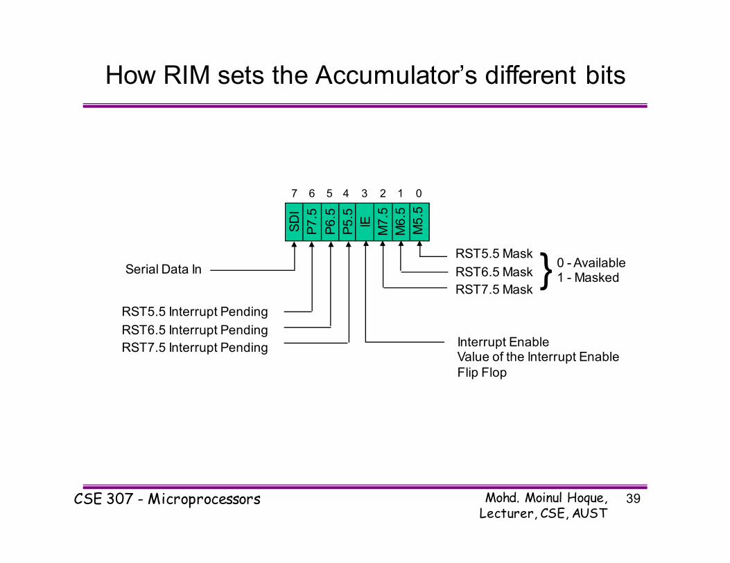
How RIM sets the Accumulator’s different bits
SD
I
P7
.5
P6
.5
P5
.5
IE
M7
.5
M6
.5
M5
.5
01234567
RST5.5 Mask
RST6.5 Mask
RST7.5 Mask} 0 - Available
1 - Masked
Interrupt EnableValue of the Interrupt Enable
Flip Flop
Serial Data In
RST5.5 Interrupt Pending
RST6.5 Interrupt Pending
RST7.5 Interrupt Pending

Mohd. Moinul Hoque, Lecturer, CSE, AUST
CSE 307 - Microprocessors 40
The RIM Instruction and the Masks
• Bits 0-2 show the current setting of the mask for
each of RST 7.5, RST 6.5 and RST 5.5
• They return the contents of the three mask flip flops.
• They can be used by a program to read the mask
settings in order to modify only the right mask.
• Bit 3 shows whether the maskable interrupt
process is enabled or not.• It returns the contents of the Interrupt Enable Flip Flop.
• It can be used by a program to determine whether or not
interrupts are enabled.
Mohd. Moinul Hoque, Lecturer, CSE, AUST
CSE 307 - Microprocessors 41
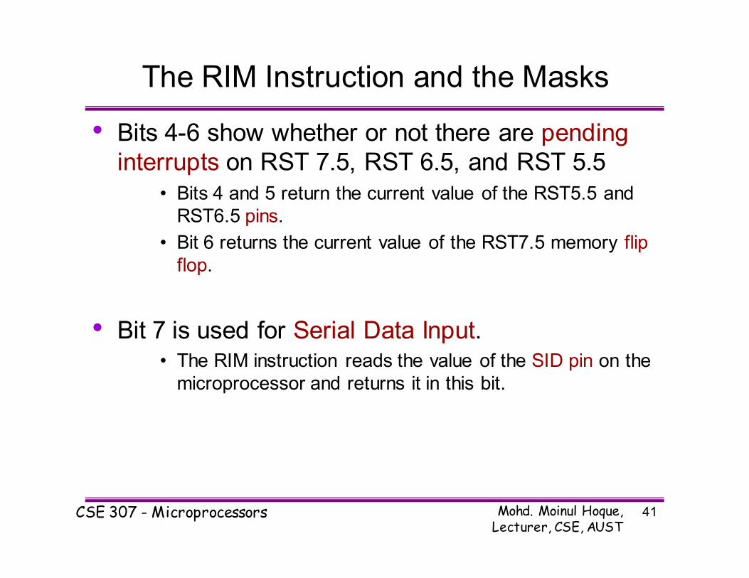
The RIM Instruction and the Masks
• Bits 4-6 show whether or not there are pending
interrupts on RST 7.5, RST 6.5, and RST 5.5
• Bits 4 and 5 return the current value of the RST5.5 and
RST6.5 pins.
• Bit 6 returns the current value of the RST7.5 memory flip
flop.
• Bit 7 is used for Serial Data Input.• The RIM instruction reads the value of the SID pin on the
microprocessor and returns it in this bit.

Mohd. Moinul Hoque, Lecturer, CSE, AUST
CSE 307 - Microprocessors 42
Pending Interrupts
• Since the 8085 has five interrupt lines, interrupts
may occur during an ISR and remain pending.
– Using the RIM instruction, it is possible to can read the status of the interrupt lines and find if
there are any pending interrupts.
– See the example of the class

Mohd. Moinul Hoque, Lecturer, CSE, AUST
CSE 307 - Microprocessors 43
TRAP
• TRAP is the only non-maskable interrupt.
– It does not need to be enabled because it cannot
be disabled.
• It has the highest priority amongst interrupts.
• It is edge and level sensitive.
– It needs to be high and stay high to be recognized.
– Once it is recognized, it won’t be recognized again
until it goes low, then high again.
• TRAP is usually used for power failure and
emergency shutoff.

Mohd. Moinul Hoque, Lecturer, CSE, AUST
CSE 307 - Microprocessors 44
The 8085 Interrupts
Interrupt Name
MaskableMasking Method
Vectored MemoryTriggering
Method
INTR Yes DI / EI No NoLevel
Sensitive
RST 5.5 / RST 6.5
YesDI / EI
SIMYes No
Level Sensitive
RST 7.5 YesDI / EI
SIMYes Yes
Edge Sensitive
TRAP No None Yes NoLevel & Edge
Sensitive