chapter 1 general information - … information 1.2 specifications model scrambler 50 scrambler 90...
TRANSCRIPT
1CHAPTER 1GENERAL INFORMATION
Model Identification 1.1. . . . . . . . . . . . . . . . . . . . . . . . . . .
Serial Number Location 1.1. . . . . . . . . . . . . . . . . . . . . . .
Specifications - General 1.2. . . . . . . . . . . . . . . . . . . . . . .
Publication Numbers 1.3. . . . . . . . . . . . . . . . . . . . . . . . . .
Paint Codes 1.3. . . . . . . . . . . . . . . . . . . . . . . . . . . . . . . . .
Standard Torque Specifications 1.4. . . . . . . . . . . . . . . . .
Lubricant and Maintenance Part Numbers 1.4. . . . . . .
Torque Conversion Table 1.5-1.6. . . . . . . . . . . . . . . . . . . . . .
Decimal Equivalent Chart 1.7. . . . . . . . . . . . . . . . . . . . . .
Unit of Measure Conversion Table 1.8. . . . . . . . . . . . . .
Tap Drill Charts 1.9. . . . . . . . . . . . . . . . . . . . . . . . . . . . . . .
Glossary of Terms 1.10-1.11. . . . . . . . . . . . . . . . . . . . . . . . . . . .
Inspection Schedule 1.12. . . . . . . . . . . . . . . . . . . . . . . . . .
Vehicle Inspection 1.13-1.15. . . . . . . . . . . . . . . . . . . . . . . . . . . .
Transmission Lubrication 1.16. . . . . . . . . . . . . . . . . . . . . .
Throttle Operation / Air Screw Adjustment 1.17. . . . . . .
Idle Speed Adjustment 1.18. . . . . . . . . . . . . . . . . . . . . . . .
Throttle Cable Adjustment 1.18-1.19. . . . . . . . . . . . . . . . . . . . .
Oil Pump Adjustment / Bleeding 1.20. . . . . . . . . . . . . . . .
Oil Pump Troubleshooting 1.21. . . . . . . . . . . . . . . . . . . . .
Fuel System 1.22-1.23. . . . . . . . . . . . . . . . . . . . . . . . . . . . . . . . .
Compression Test 1.24. . . . . . . . . . . . . . . . . . . . . . . . . . . .
Air Filter Service 1.24. . . . . . . . . . . . . . . . . . . . . . . . . . . . . .
Wheels and Tires 1.25-1.26. . . . . . . . . . . . . . . . . . . . . . . . . . . . .
Alignment 1.27-1.28. . . . . . . . . . . . . . . . . . . . . . . . . . . . . . . . . . .

GENERAL INFORMATION
1.1
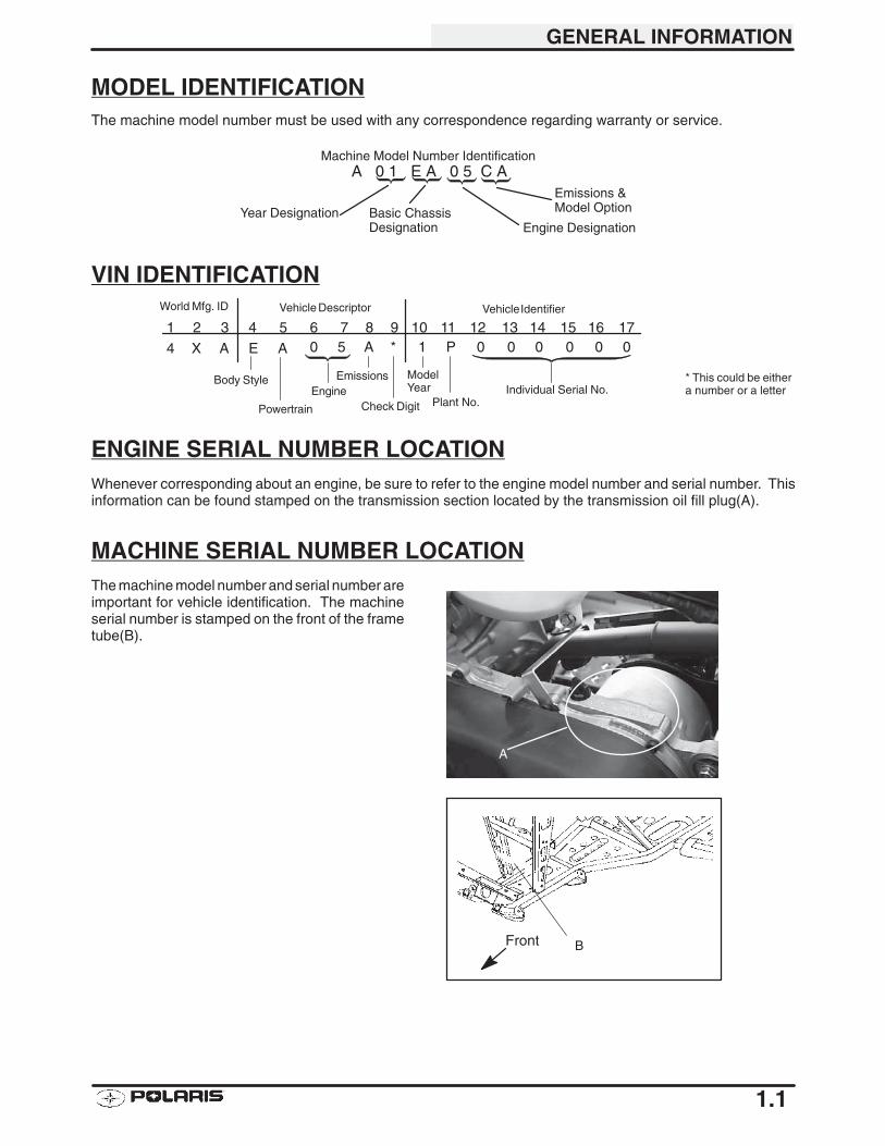
MODEL IDENTIFICATIONThe machine model number must be used with any correspondence regarding warranty or service.
Machine Model Number Identification
Year Designation Basic ChassisDesignation Engine Designation
A 0 1 E A 0 5 C AEmissions &Model Option
VIN IDENTIFICATION
1 2 3 4 5 6 7 8 9 10 11 12 13 14 15 16 174 X A E A 0 5 A * 1 P 0 0 0 0 0 0
Vehicle Descriptor Vehicle Identifier
Powertrain
EngineEmissions Model
YearPlant No.
Individual Serial No.Body Style
Check Digit
World Mfg. ID
* This could be eithera number or a letter
ENGINE SERIAL NUMBER LOCATIONWhenever corresponding about an engine, be sure to refer to the engine model number and serial number. Thisinformation can be found stamped on the transmission section located by the transmission oil fill plug(A).
MACHINE SERIAL NUMBER LOCATIONThe machine model number and serial number areimportant for vehicle identification. The machineserial number is stamped on the front of the frametube(B).
Front B
A
GENERAL INFORMATION
1.2
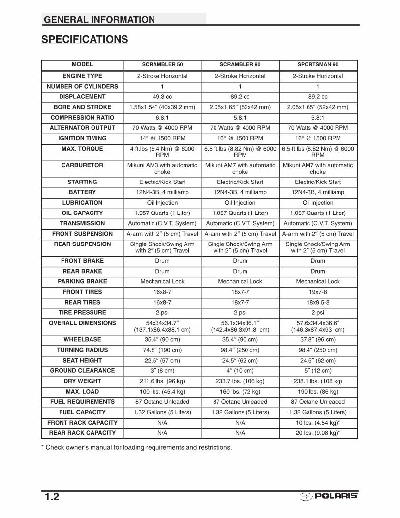
SPECIFICATIONS
MODEL SCRAMBLER 50 SCRAMBLER 90 SPORTSMAN 90
ENGINE TYPE 2-Stroke Horizontal 2-Stroke Horizontal 2-Stroke Horizontal
NUMBER OF CYLINDERS 1 1 1
DISPLACEMENT 49.3 cc 89.2 cc 89.2 cc
BORE AND STROKE 1.58x1.54″ (40x39.2 mm) 2.05x1.65″ (52x42 mm) 2.05x1.65″ (52x42 mm)
COMPRESSION RATIO 6.8:1 5.8:1 5.8:1
ALTERNATOR OUTPUT 70 Watts @ 4000 RPM 70 Watts @ 4000 RPM 70 Watts @ 4000 RPM
IGNITION TIMING 14° @ 1500 RPM 16° @ 1500 RPM 16° @ 1500 RPM
MAX. TORQUE 4 ft.lbs (5.4 Nm) @ 6000RPM
6.5 ft.lbs (8.82 Nm) @ 6000RPM
6.5 ft.lbs (8.82 Nm) @ 6000RPM
CARBURETOR Mikuni AM3 with automaticchoke
Mikuni AM7 with automaticchoke
Mikuni AM7 with automaticchoke
STARTING Electric/Kick Start Electric/Kick Start Electric/Kick Start
BATTERY 12N4-3B, 4 milliamp 12N4-3B, 4 milliamp 12N4-3B, 4 milliamp
LUBRICATION Oil Injection Oil Injection Oil Injection
OIL CAPACITY 1.057 Quarts (1 Liter) 1.057 Quarts (1 Liter) 1.057 Quarts (1 Liter)
TRANSMISSION Automatic (C.V.T. System) Automatic (C.V.T. System) Automatic (C.V.T. System)
FRONT SUSPENSION A-arm with 2″ (5 cm) Travel A-arm with 2″ (5 cm) Travel A-arm with 2″ (5 cm) Travel
REAR SUSPENSION Single Shock/Swing Armwith 2″ (5 cm) Travel
Single Shock/Swing Armwith 2″ (5 cm) Travel
Single Shock/Swing Armwith 2″ (5 cm) Travel
FRONT BRAKE Drum Drum Drum
REAR BRAKE Drum Drum Drum
PARKING BRAKE Mechanical Lock Mechanical Lock Mechanical Lock
FRONT TIRES 16x8-7 18x7-7 19x7-8
REAR TIRES 16x8-7 18x7-7 18x9.5-8
TIRE PRESSURE 2 psi 2 psi 2 psi
OVERALL DIMENSIONS 54x34x34.7″(137.1x86.4x88.1 cm)
56.1x34x36.1″(142.4x86.3x91.8 cm)
57.6x34.4x36.6″(146.3x87.4x93 cm)
WHEELBASE 35.4″ (90 cm) 35.4″ (90 cm) 37.8″ (96 cm)
TURNING RADIUS 74.8″ (190 cm) 98.4″ (250 cm) 98.4″ (250 cm)
SEAT HEIGHT 22.5″ (57 cm) 24.5″ (62 cm) 24.5″ (62 cm)
GROUND CLEARANCE 3″ (8 cm) 4″ (10 cm) 5″ (12 cm)
DRY WEIGHT 211.6 lbs. (96 kg) 233.7 lbs. (106 kg) 238.1 lbs. (108 kg)
MAX. LOAD 100 lbs. (45.4 kg) 160 lbs. (72 kg) 190 lbs. (86 kg)
FUEL REQUIREMENTS 87 Octane Unleaded 87 Octane Unleaded 87 Octane Unleaded
FUEL CAPACITY 1.32 Gallons (5 Liters) 1.32 Gallons (5 Liters) 1.32 Gallons (5 Liters)
FRONT RACK CAPACITY N/A N/A 10 lbs. (4.54 kg)*
REAR RACK CAPACITY N/A N/A 20 lbs. (9.08 kg)*
* Check owner’s manual for loading requirements and restrictions.
GENERAL INFORMATION
1.3
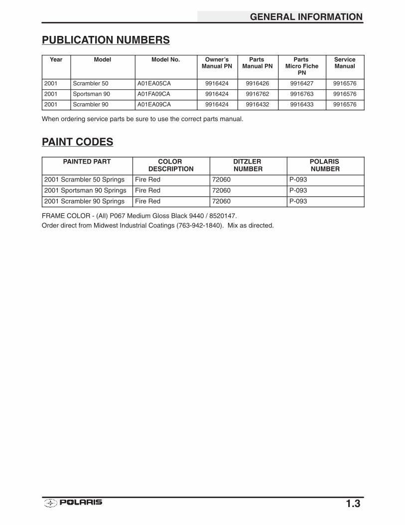
PUBLICATION NUMBERS
Year Model Model No. Owner’sManual PN
Parts Manual PN
Parts Micro Fiche
PN
ServiceManual
2001 Scrambler 50 A01EA05CA 9916424 9916426 9916427 9916576
2001 Sportsman 90 A01FA09CA 9916424 9916762 9916763 9916576
2001 Scrambler 90 A01EA09CA 9916424 9916432 9916433 9916576
When ordering service parts be sure to use the correct parts manual.
PAINT CODES
PAINTED PART COLOR DESCRIPTION
DITZLER NUMBER
POLARIS NUMBER
2001 Scrambler 50 Springs Fire Red 72060 P-093
2001 Sportsman 90 Springs Fire Red 72060 P-093
2001 Scrambler 90 Springs Fire Red 72060 P-093
FRAME COLOR - (All) P067 Medium Gloss Black 9440 / 8520147.
Order direct from Midwest Industrial Coatings (763-942-1840). Mix as directed.
GENERAL INFORMATION
1.4
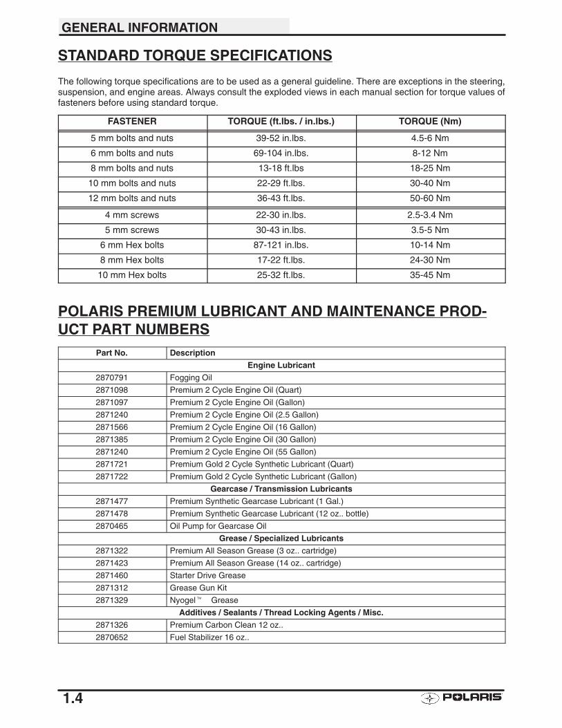
STANDARD TORQUE SPECIFICATIONS
The following torque specifications are to be used as a general guideline. There are exceptions in the steering,suspension, and engine areas. Always consult the exploded views in each manual section for torque values offasteners before using standard torque.
FASTENER TORQUE (ft.lbs. / in.lbs.) TORQUE (Nm)
5 mm bolts and nuts 39-52 in.lbs. 4.5-6 Nm
6 mm bolts and nuts 69-104 in.lbs. 8-12 Nm
8 mm bolts and nuts 13-18 ft.lbs 18-25 Nm
10 mm bolts and nuts 22-29 ft.lbs. 30-40 Nm
12 mm bolts and nuts 36-43 ft.lbs. 50-60 Nm
4 mm screws 22-30 in.lbs. 2.5-3.4 Nm
5 mm screws 30-43 in.lbs. 3.5-5 Nm
6 mm Hex bolts 87-121 in.lbs. 10-14 Nm
8 mm Hex bolts 17-22 ft.lbs. 24-30 Nm
10 mm Hex bolts 25-32 ft.lbs. 35-45 Nm
POLARIS PREMIUM LUBRICANT AND MAINTENANCE PROD-UCT PART NUMBERS
Part No. Description
Engine Lubricant
2870791 Fogging Oil
2871098 Premium 2 Cycle Engine Oil (Quart)
2871097 Premium 2 Cycle Engine Oil (Gallon)
2871240 Premium 2 Cycle Engine Oil (2.5 Gallon)
2871566 Premium 2 Cycle Engine Oil (16 Gallon)
2871385 Premium 2 Cycle Engine Oil (30 Gallon)
2871240 Premium 2 Cycle Engine Oil (55 Gallon)
2871721 Premium Gold 2 Cycle Synthetic Lubricant (Quart)
2871722 Premium Gold 2 Cycle Synthetic Lubricant (Gallon)
Gearcase / Transmission Lubricants
2871477 Premium Synthetic Gearcase Lubricant (1 Gal.)
2871478 Premium Synthetic Gearcase Lubricant (12 oz.. bottle)
2870465 Oil Pump for Gearcase Oil
Grease / Specialized Lubricants
2871322 Premium All Season Grease (3 oz.. cartridge)
2871423 Premium All Season Grease (14 oz.. cartridge)
2871460 Starter Drive Grease
2871312 Grease Gun Kit
2871329 Nyogel��Grease
Additives / Sealants / Thread Locking Agents / Misc.
2871326 Premium Carbon Clean 12 oz..
2870652 Fuel Stabilizer 16 oz..
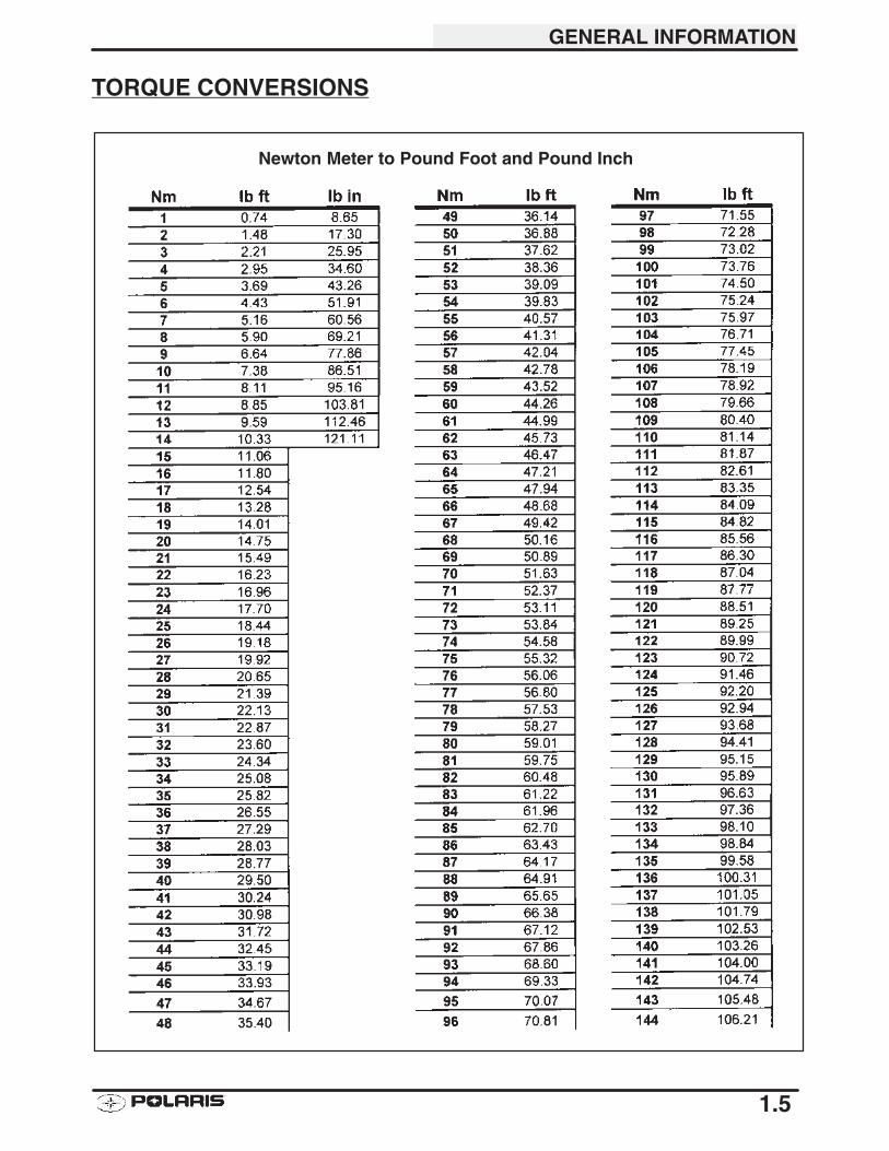
Newton Meter to Pound Foot and Pound Inch
GENERAL INFORMATION
1.5
TORQUE CONVERSIONS
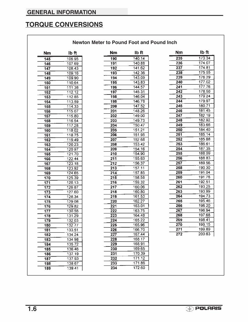
Newton Meter to Pound Foot and Pound Inch
GENERAL INFORMATION
1.6
TORQUE CONVERSIONS
GENERAL INFORMATION
1.7
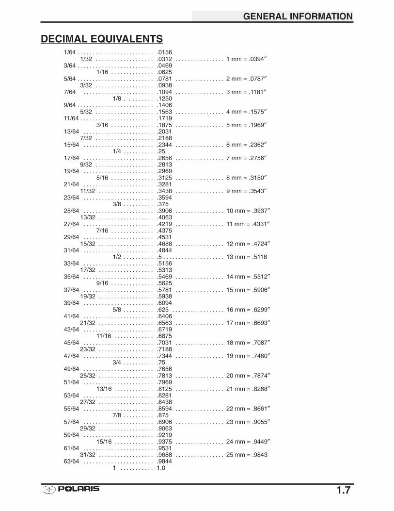
DECIMAL EQUIVALENTS1/64 .0156. . . . . . . . . . . . . . . . . . . . . . . . .
1/32 .0312 1 mm = .0394″. . . . . . . . . . . . . . . . . . . . . . . . . . . . . . . . . . . 3/64 .0469. . . . . . . . . . . . . . . . . . . . . . . . .
1/16 .0625. . . . . . . . . . . . . . 5/64 .0781 2 mm = .0787″. . . . . . . . . . . . . . . . . . . . . . . . . . . . . . . . . . . . . . . . .
3/32 .0938. . . . . . . . . . . . . . . . . . . 7/64 .1094 3 mm = .1181″. . . . . . . . . . . . . . . . . . . . . . . . . . . . . . . . . . . . . . .
1/8 . .1250. . . . . . . . 9/64 .1406. . . . . . . . . . . . . . . . . . . . . . . . .
5/32 .1563 4 mm = .1575″. . . . . . . . . . . . . . . . . . . . . . . . . . . . . . . . . . . 11/64 .1719. . . . . . . . . . . . . . . . . . . . . . . .
3/16 .1875 5 mm = .1969″. . . . . . . . . . . . . . . . . . . . . . . . . . . . . . 13/64 .2031. . . . . . . . . . . . . . . . . . . . . . .
7/32 .2188. . . . . . . . . . . . . . . . . . . 15/64 .2344 6 mm = .2362″. . . . . . . . . . . . . . . . . . . . . . . . . . . . . . . . . . . . . . .
1/4 .25. . . . . . . . . . 17/64 .2656 7 mm = .2756″. . . . . . . . . . . . . . . . . . . . . . . . . . . . . . . . . . . . . . .
9/32 .2813. . . . . . . . . . . . . . . . . . . 19/64 .2969. . . . . . . . . . . . . . . . . . . . . . .
5/16 .3125 8 mm = .3150″. . . . . . . . . . . . . . . . . . . . . . . . . . . . . . 21/64 .3281. . . . . . . . . . . . . . . . . . . . . . .
11/32 .3438 9 mm = .3543″. . . . . . . . . . . . . . . . . . . . . . . . . . . . . . . . . . 23/64 .3594. . . . . . . . . . . . . . . . . . . . . . .
3/8 .375. . . . . . . . . . 25/64 .3906 10 mm = .3937″. . . . . . . . . . . . . . . . . . . . . . . . . . . . . . . . . . . . . . .
13/32 .4063. . . . . . . . . . . . . . . . . . 27/64 .4219 11 mm = .4331″. . . . . . . . . . . . . . . . . . . . . . . . . . . . . . . . . . . . . . .
7/16 .4375. . . . . . . . . . . . . . 29/64 .4531. . . . . . . . . . . . . . . . . . . . . . .
15/32 .4688 12 mm = .4724″. . . . . . . . . . . . . . . . . . . . . . . . . . . . . . . . . . 31/64 .4844. . . . . . . . . . . . . . . . . . . . . . .
1/2 .5 13 mm = .5118. . . . . . . . . . . . . . . . . . . . . . . . . . . . . . 33/64 .5156. . . . . . . . . . . . . . . . . . . . . . .
17/32 .5313. . . . . . . . . . . . . . . . . . 35/64 .5469 14 mm = .5512″. . . . . . . . . . . . . . . . . . . . . . . . . . . . . . . . . . . . . . .
9/16 .5625. . . . . . . . . . . . . . 37/64 .5781 15 mm = .5906″. . . . . . . . . . . . . . . . . . . . . . . . . . . . . . . . . . . . . . .
19/32 .5938. . . . . . . . . . . . . . . . . . 39/64 .6094. . . . . . . . . . . . . . . . . . . . . . .
5/8 .625 16 mm = .6299″. . . . . . . . . . . . . . . . . . . . . . . . . . . 41/64 .6406. . . . . . . . . . . . . . . . . . . . . . .
21/32 .6563 17 mm = .6693″. . . . . . . . . . . . . . . . . . . . . . . . . . . . . . . . . . 43/64 .6719. . . . . . . . . . . . . . . . . . . . . . .
11/16 .6875. . . . . . . . . . . . . 45/64 .7031 18 mm = .7087″. . . . . . . . . . . . . . . . . . . . . . . . . . . . . . . . . . . . . . .
23/32 .7188. . . . . . . . . . . . . . . . . . 47/64 .7344 19 mm = .7480″. . . . . . . . . . . . . . . . . . . . . . . . . . . . . . . . . . . . . . .
3/4 .75. . . . . . . . . . 49/64 .7656. . . . . . . . . . . . . . . . . . . . . . .
25/32 .7813 20 mm = .7874″. . . . . . . . . . . . . . . . . . . . . . . . . . . . . . . . . . 51/64 .7969. . . . . . . . . . . . . . . . . . . . . . .
13/16 .8125 21 mm = .8268″. . . . . . . . . . . . . . . . . . . . . . . . . . . . . 53/64 .8281. . . . . . . . . . . . . . . . . . . . . . .
27/32 .8438. . . . . . . . . . . . . . . . . . 55/64 .8594 22 mm = .8661″. . . . . . . . . . . . . . . . . . . . . . . . . . . . . . . . . . . . . . .
7/8 .875. . . . . . . . . . 57/64 .8906 23 mm = .9055″. . . . . . . . . . . . . . . . . . . . . . . . . . . . . . . . . . . . . . .
29/32 .9063. . . . . . . . . . . . . . . . . . 59/64 .9219. . . . . . . . . . . . . . . . . . . . . . .
15/16 .9375 24 mm = .9449″. . . . . . . . . . . . . . . . . . . . . . . . . . . . . 61/64 .9531. . . . . . . . . . . . . . . . . . . . . . .
31/32 .9688 25 mm = .9843. . . . . . . . . . . . . . . . . . . . . . . . . . . . . . . . . . 63/64 .9844. . . . . . . . . . . . . . . . . . . . . . .
1 1.0. . . . . . . . . . .
GENERAL INFORMATION
1.8
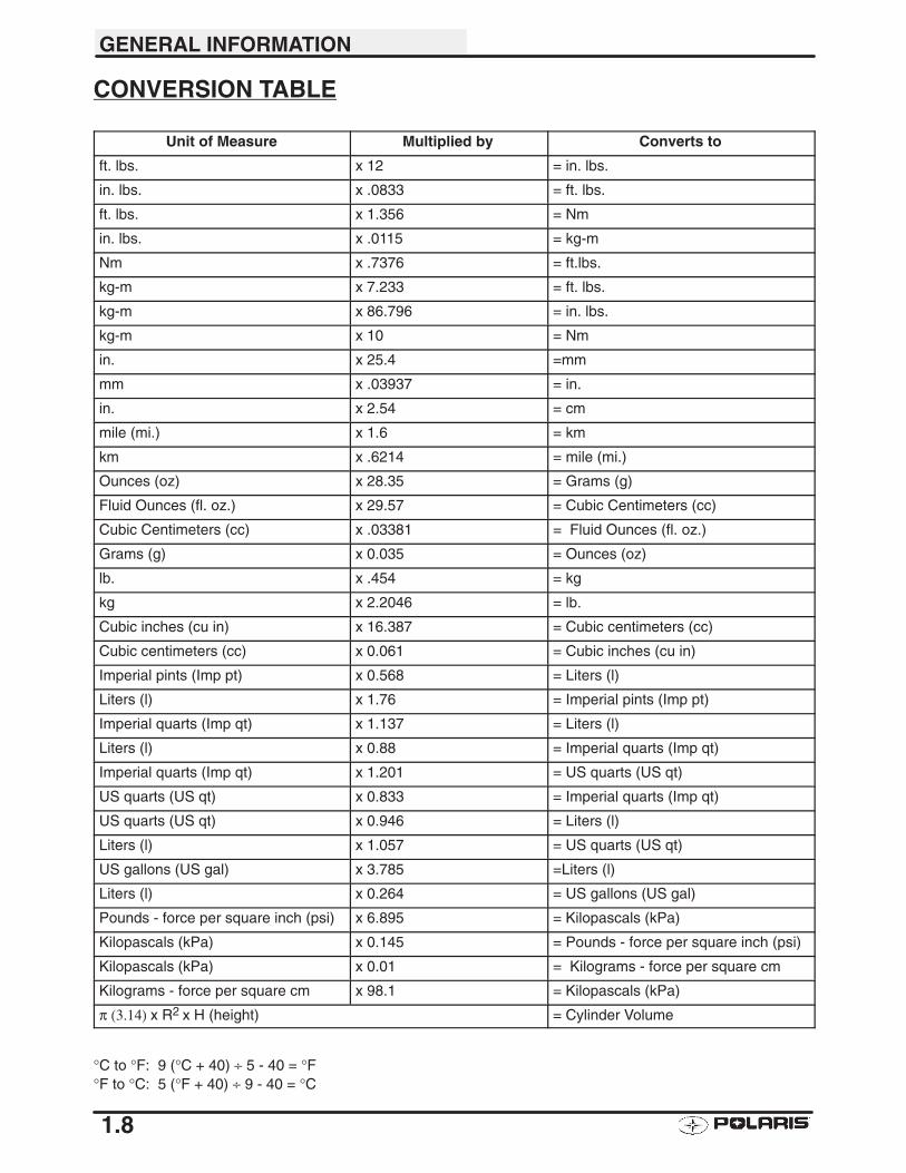
CONVERSION TABLE
Unit of Measure Multiplied by Converts to
ft. lbs. x 12 = in. lbs.
in. lbs. x .0833 = ft. lbs.
ft. lbs. x 1.356 = Nm
in. lbs. x .0115 = kg-m
Nm x .7376 = ft.lbs.
kg-m x 7.233 = ft. lbs.
kg-m x 86.796 = in. lbs.
kg-m x 10 = Nm
in. x 25.4 =mm
mm x .03937 = in.
in. x 2.54 = cm
mile (mi.) x 1.6 = km
km x .6214 = mile (mi.)
Ounces (oz) x 28.35 = Grams (g)
Fluid Ounces (fl. oz.) x 29.57 = Cubic Centimeters (cc)
Cubic Centimeters (cc) x .03381 = Fluid Ounces (fl. oz.)
Grams (g) x 0.035 = Ounces (oz)
lb. x .454 = kg
kg x 2.2046 = lb.
Cubic inches (cu in) x 16.387 = Cubic centimeters (cc)
Cubic centimeters (cc) x 0.061 = Cubic inches (cu in)
Imperial pints (Imp pt) x 0.568 = Liters (l)
Liters (l) x 1.76 = Imperial pints (Imp pt)
Imperial quarts (Imp qt) x 1.137 = Liters (l)
Liters (l) x 0.88 = Imperial quarts (Imp qt)
Imperial quarts (Imp qt) x 1.201 = US quarts (US qt)
US quarts (US qt) x 0.833 = Imperial quarts (Imp qt)
US quarts (US qt) x 0.946 = Liters (l)
Liters (l) x 1.057 = US quarts (US qt)
US gallons (US gal) x 3.785 =Liters (l)
Liters (l) x 0.264 = US gallons (US gal)
Pounds - force per square inch (psi) x 6.895 = Kilopascals (kPa)
Kilopascals (kPa) x 0.145 = Pounds - force per square inch (psi)
Kilopascals (kPa) x 0.01 = Kilograms - force per square cm
Kilograms - force per square cm x 98.1 = Kilopascals (kPa)
π (3.14) x R2 x H (height) = Cylinder Volume
°C to °F: 9 (°C + 40) ÷ 5 - 40 = °F°F to °C: 5 (°F + 40) ÷ 9 - 40 = °C
GENERAL INFORMATION
1.9
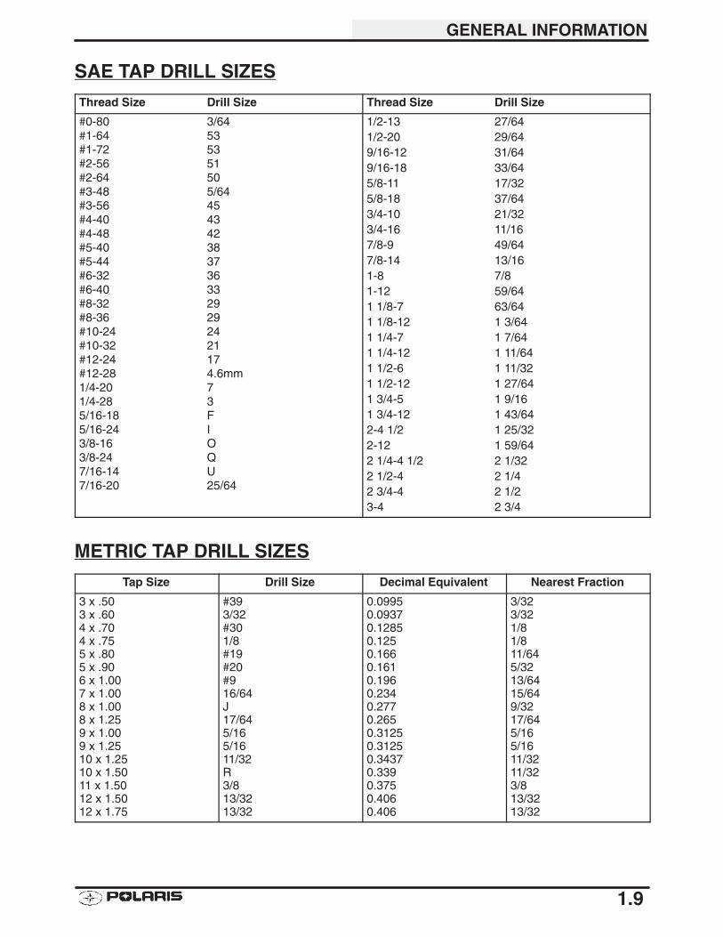
SAE TAP DRILL SIZES
Thread Size Drill Size Thread Size Drill Size
#0-80 3/64#1-64 53#1-72 53#2-56 51#2-64 50#3-48 5/64#3-56 45#4-40 43#4-48 42#5-40 38#5-44 37#6-32 36#6-40 33#8-32 29#8-36 29#10-24 24#10-32 21#12-24 17#12-28 4.6mm1/4-20 71/4-28 35/16-18 F5/16-24 I3/8-16 O3/8-24 Q7/16-14 U7/16-20 25/64
1/2-13 27/641/2-20 29/649/16-12 31/649/16-18 33/645/8-11 17/325/8-18 37/643/4-10 21/323/4-16 11/167/8-9 49/647/8-14 13/161-8 7/81-12 59/641 1/8-7 63/641 1/8-12 1 3/641 1/4-7 1 7/641 1/4-12 1 11/641 1/2-6 1 11/321 1/2-12 1 27/641 3/4-5 1 9/161 3/4-12 1 43/642-4 1/2 1 25/322-12 1 59/642 1/4-4 1/2 2 1/322 1/2-4 2 1/42 3/4-4 2 1/23-4 2 3/4
METRIC TAP DRILL SIZES
Tap Size Drill Size Decimal Equivalent Nearest Fraction
3 x .503 x .604 x .704 x .755 x .805 x .906 x 1.007 x 1.008 x 1.008 x 1.259 x 1.009 x 1.2510 x 1.2510 x 1.5011 x 1.5012 x 1.5012 x 1.75
#393/32#301/8#19#20#916/64J17/645/165/1611/32R3/813/3213/32
0.09950.09370.12850.1250.1660.1610.1960.2340.2770.2650.31250.31250.34370.3390.3750.4060.406
3/323/321/81/811/645/3213/6415/649/3217/645/165/1611/3211/323/813/3213/32
GENERAL INFORMATION
1.10
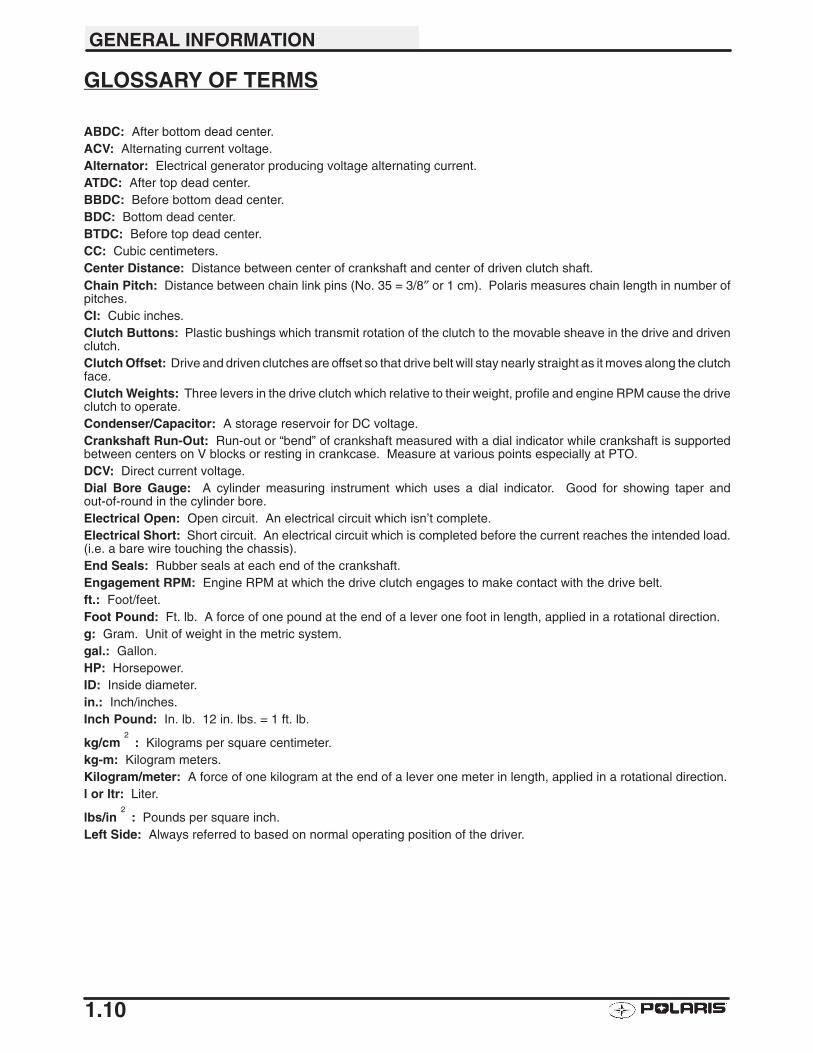
GLOSSARY OF TERMS
ABDC: After bottom dead center.ACV: Alternating current voltage.Alternator: Electrical generator producing voltage alternating current.ATDC: After top dead center.BBDC: Before bottom dead center.BDC: Bottom dead center.BTDC: Before top dead center.CC: Cubic centimeters.Center Distance: Distance between center of crankshaft and center of driven clutch shaft.Chain Pitch: Distance between chain link pins (No. 35 = 3/8″ or 1 cm). Polaris measures chain length in number ofpitches.CI: Cubic inches.Clutch Buttons: Plastic bushings which transmit rotation of the clutch to the movable sheave in the drive and drivenclutch.Clutch Offset: Drive and driven clutches are offset so that drive belt will stay nearly straight as it moves along the clutchface.Clutch Weights: Three levers in the drive clutch which relative to their weight, profile and engine RPM cause the driveclutch to operate.Condenser/Capacitor: A storage reservoir for DC voltage.Crankshaft Run-Out: Run-out or “bend” of crankshaft measured with a dial indicator while crankshaft is supportedbetween centers on V blocks or resting in crankcase. Measure at various points especially at PTO.DCV: Direct current voltage.Dial Bore Gauge: A cylinder measuring instrument which uses a dial indicator. Good for showing taper andout-of-round in the cylinder bore.Electrical Open: Open circuit. An electrical circuit which isn’t complete.Electrical Short: Short circuit. An electrical circuit which is completed before the current reaches the intended load.(i.e. a bare wire touching the chassis).End Seals: Rubber seals at each end of the crankshaft.Engagement RPM: Engine RPM at which the drive clutch engages to make contact with the drive belt.ft.: Foot/feet.Foot Pound: Ft. lb. A force of one pound at the end of a lever one foot in length, applied in a rotational direction.g: Gram. Unit of weight in the metric system.gal.: Gallon.HP: Horsepower.ID: Inside diameter.in.: Inch/inches.Inch Pound: In. lb. 12 in. lbs. = 1 ft. lb.
kg/cm2
: Kilograms per square centimeter.kg-m: Kilogram meters.Kilogram/meter: A force of one kilogram at the end of a lever one meter in length, applied in a rotational direction.l or ltr: Liter.
lbs/in2
: Pounds per square inch.Left Side: Always referred to based on normal operating position of the driver.
GENERAL INFORMATION
1.11
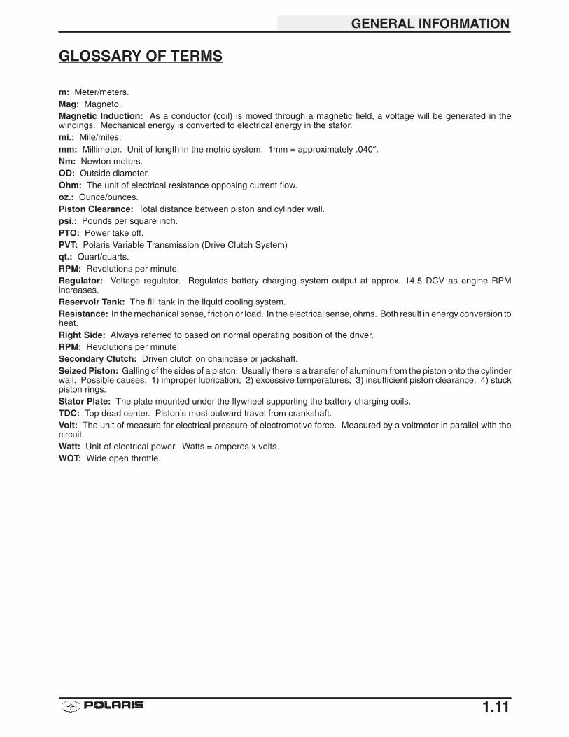
GLOSSARY OF TERMS
m: Meter/meters.Mag: Magneto.Magnetic Induction: As a conductor (coil) is moved through a magnetic field, a voltage will be generated in thewindings. Mechanical energy is converted to electrical energy in the stator.mi.: Mile/miles.mm: Millimeter. Unit of length in the metric system. 1mm = approximately .040″.Nm: Newton meters.OD: Outside diameter.Ohm: The unit of electrical resistance opposing current flow.oz.: Ounce/ounces.Piston Clearance: Total distance between piston and cylinder wall.psi.: Pounds per square inch.PTO: Power take off.PVT: Polaris Variable Transmission (Drive Clutch System)qt.: Quart/quarts.RPM: Revolutions per minute.Regulator: Voltage regulator. Regulates battery charging system output at approx. 14.5 DCV as engine RPMincreases.Reservoir Tank: The fill tank in the liquid cooling system.Resistance: In the mechanical sense, friction or load. In the electrical sense, ohms. Both result in energy conversion toheat.Right Side: Always referred to based on normal operating position of the driver.RPM: Revolutions per minute.Secondary Clutch: Driven clutch on chaincase or jackshaft.Seized Piston: Galling of the sides of a piston. Usually there is a transfer of aluminum from the piston onto the cylinderwall. Possible causes: 1) improper lubrication; 2) excessive temperatures; 3) insufficient piston clearance; 4) stuckpiston rings.Stator Plate: The plate mounted under the flywheel supporting the battery charging coils.TDC: Top dead center. Piston’s most outward travel from crankshaft.Volt: The unit of measure for electrical pressure of electromotive force. Measured by a voltmeter in parallel with thecircuit.Watt: Unit of electrical power. Watts = amperes x volts.WOT: Wide open throttle.
GENERAL INFORMATION
1.12
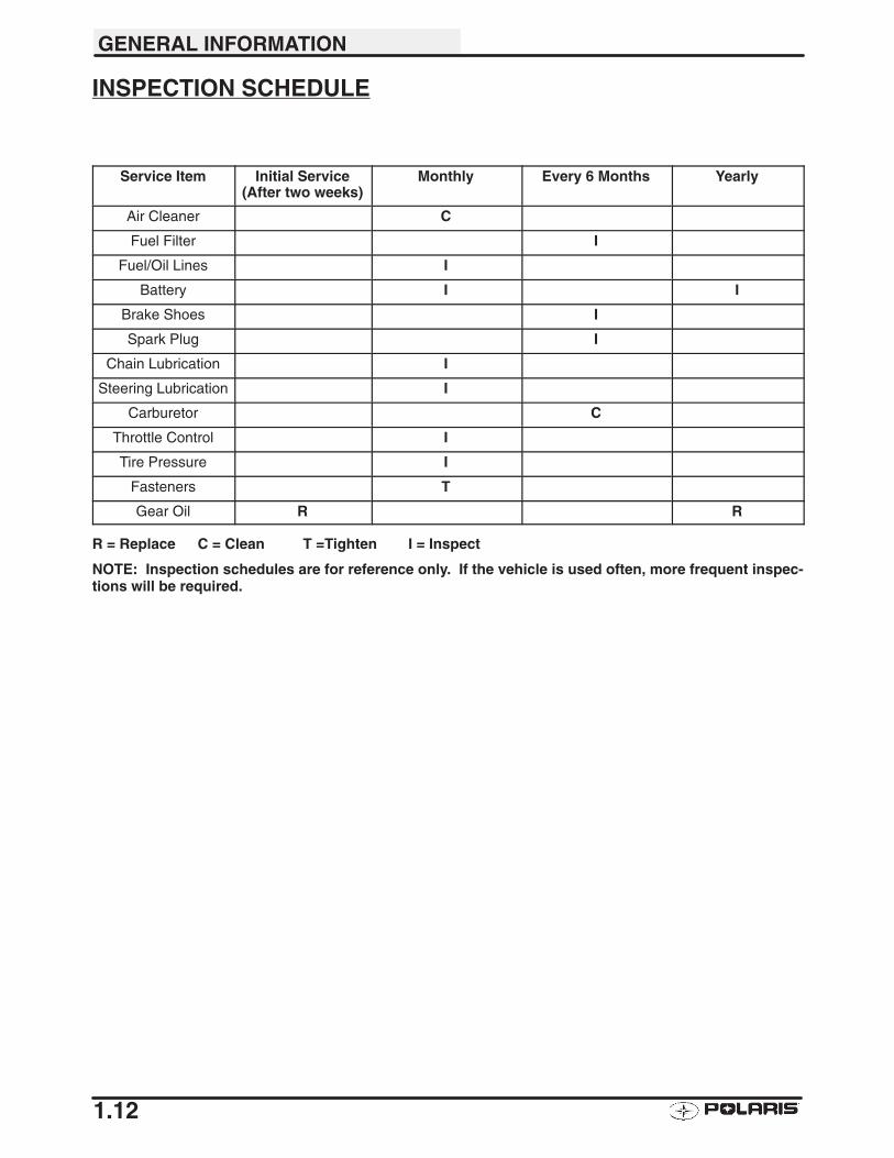
INSPECTION SCHEDULE
Service Item Initial Service(After two weeks)
Monthly Every 6 Months Yearly
Air Cleaner C
Fuel Filter I
Fuel/Oil Lines I
Battery I I
Brake Shoes I
Spark Plug I
Chain Lubrication I
Steering Lubrication I
Carburetor C
Throttle Control I
Tire Pressure I
Fasteners T
Gear Oil R R
R = Replace C = Clean T =Tighten I = Inspect
NOTE: Inspection schedules are for reference only. If the vehicle is used often, more frequent inspec-tions will be required.
GENERAL INFORMATION
1.13
VEHICLE INSPECTION
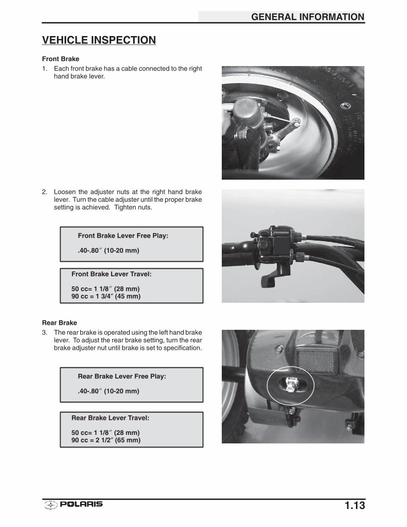
Front Brake1. Each front brake has a cable connected to the right
hand brake lever.
2. Loosen the adjuster nuts at the right hand brakelever. Turn the cable adjuster until the proper brakesetting is achieved. Tighten nuts.
Rear Brake3. The rear brake is operated using the left hand brake
lever. To adjust the rear brake setting, turn the rearbrake adjuster nut until brake is set to specification.
Front Brake Lever Free Play:
.40-.80� (10-20 mm)
Front Brake Lever Travel:
50 cc= 1 1/8� (28 mm)90 cc = 1 3/4″ (45 mm)
Rear Brake Lever Free Play:
.40-.80� (10-20 mm)
Rear Brake Lever Travel:
50 cc= 1 1/8� (28 mm)90 cc = 2 1/2″ (65 mm)
GENERAL INFORMATION
1.14
VEHICLE INSPECTION
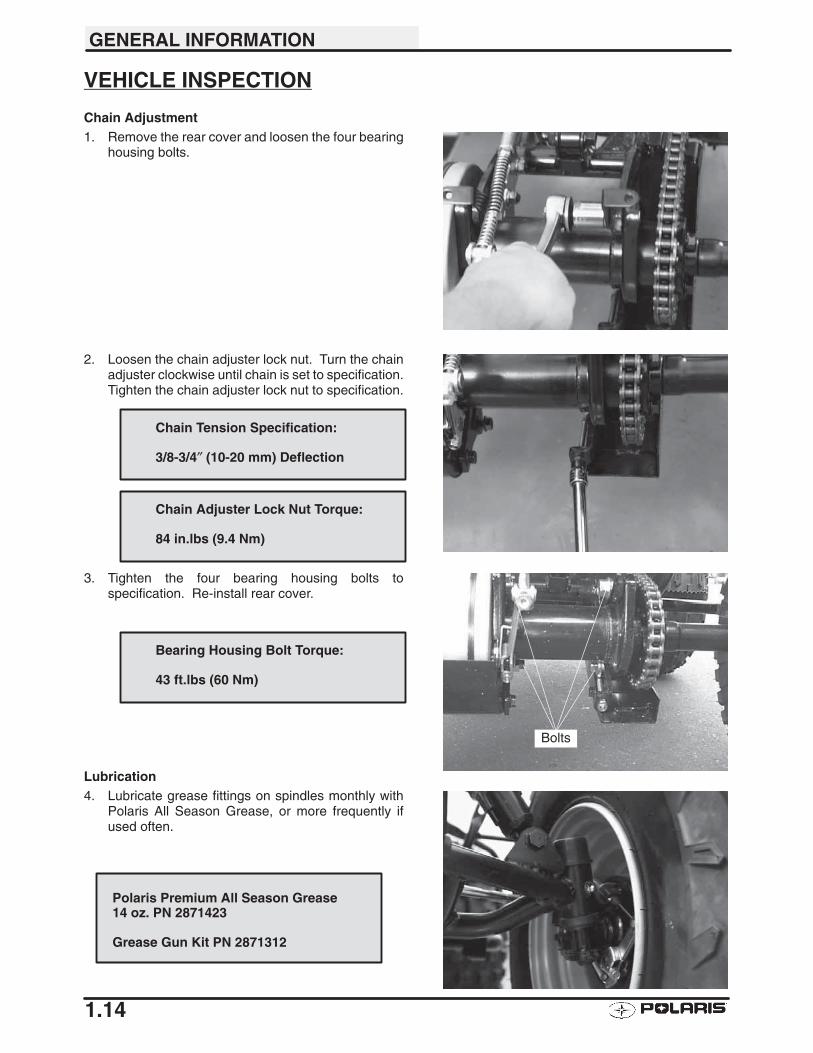
Chain Adjustment1. Remove the rear cover and loosen the four bearing
housing bolts.
2. Loosen the chain adjuster lock nut. Turn the chainadjuster clockwise until chain is set to specification.Tighten the chain adjuster lock nut to specification.
3. Tighten the four bearing housing bolts tospecification. Re-install rear cover.
Lubrication4. Lubricate grease fittings on spindles monthly with
Polaris All Season Grease, or more frequently ifused often.
Polaris Premium All Season Grease14 oz. PN 2871423
Grease Gun Kit PN 2871312
Chain Tension Specification:
3/8-3/4″ (10-20 mm) Deflection
Chain Adjuster Lock Nut Torque:
84 in.lbs (9.4 Nm)
Bolts
Bearing Housing Bolt Torque:
43 ft.lbs (60 Nm)
GENERAL INFORMATION
1.15
VEHICLE INSPECTION
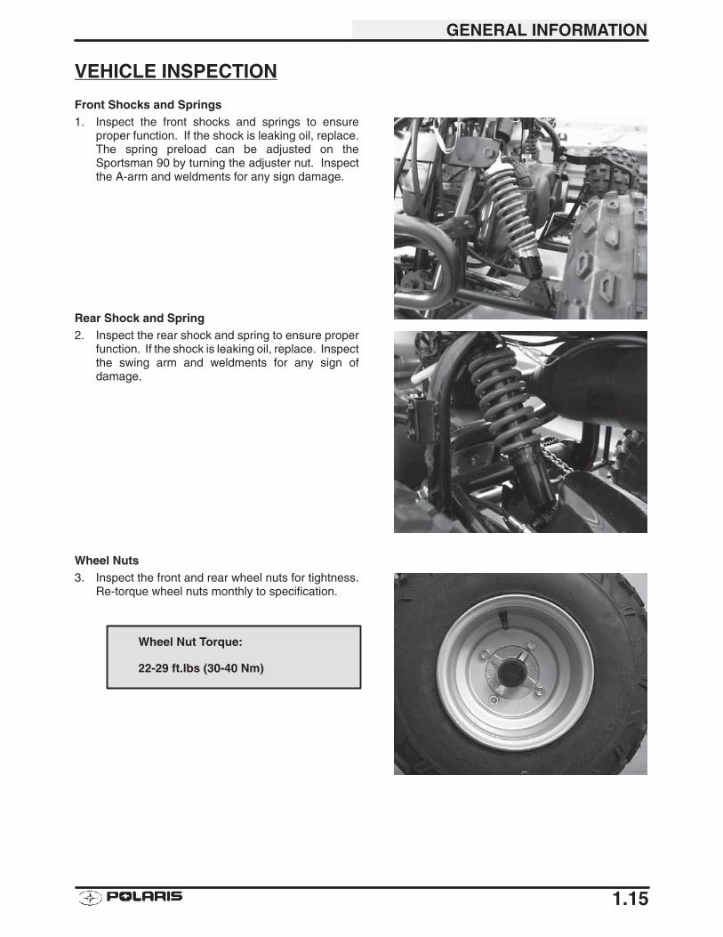
Front Shocks and Springs1. Inspect the front shocks and springs to ensure
proper function. If the shock is leaking oil, replace.The spring preload can be adjusted on theSportsman 90 by turning the adjuster nut. Inspectthe A-arm and weldments for any sign damage.
Rear Shock and Spring2. Inspect the rear shock and spring to ensure proper
function. If the shock is leaking oil, replace. Inspectthe swing arm and weldments for any sign ofdamage.
Wheel Nuts3. Inspect the front and rear wheel nuts for tightness.
Re-torque wheel nuts monthly to specification.
Wheel Nut Torque:
22-29 ft.lbs (30-40 Nm)
GENERAL INFORMATION
1.16
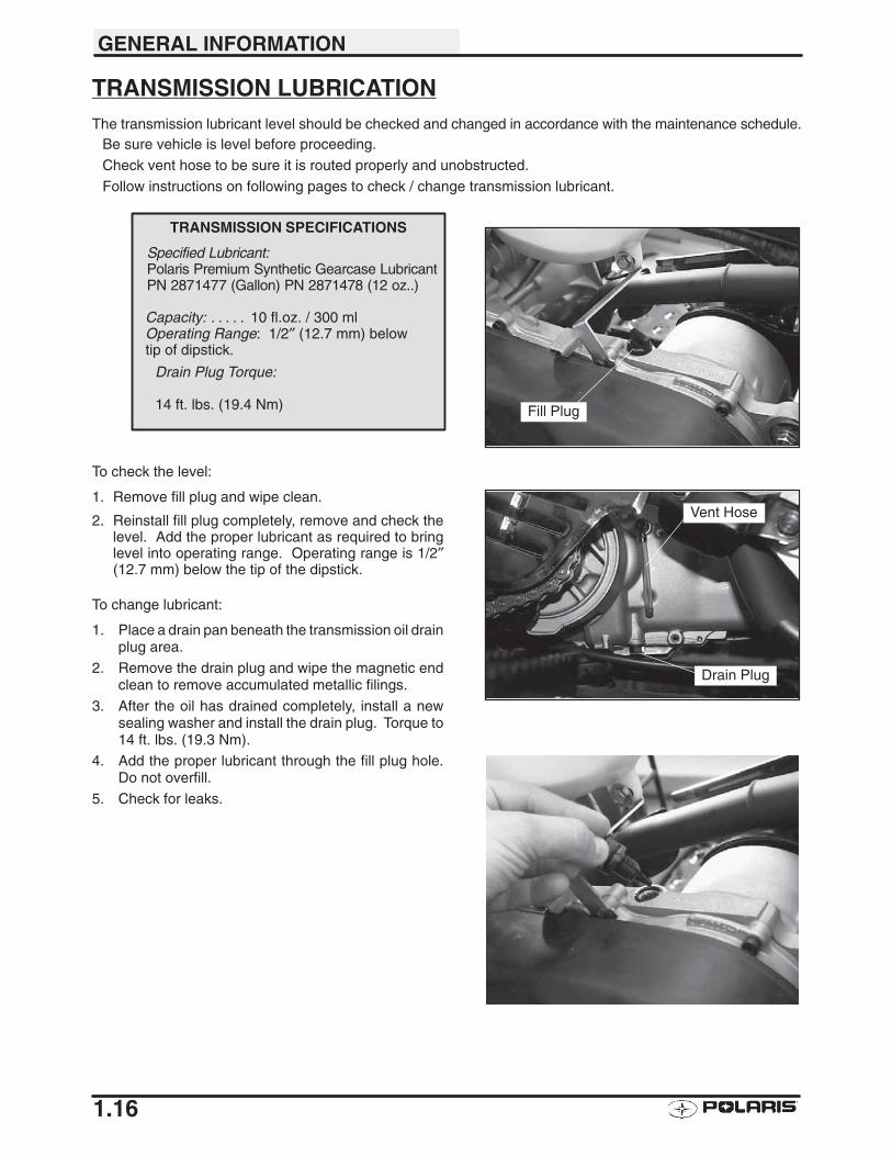
TRANSMISSION LUBRICATIONThe transmission lubricant level should be checked and changed in accordance with the maintenance schedule.
Be sure vehicle is level before proceeding.
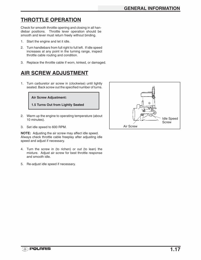
Check vent hose to be sure it is routed properly and unobstructed.
Follow instructions on following pages to check / change transmission lubricant.
To check the level:
1. Remove fill plug and wipe clean.
2. Reinstall fill plug completely, remove and check thelevel. Add the proper lubricant as required to bringlevel into operating range. Operating range is 1/2″(12.7 mm) below the tip of the dipstick.
To change lubricant:
1. Place a drain pan beneath the transmission oil drainplug area.
2. Remove the drain plug and wipe the magnetic endclean to remove accumulated metallic filings.
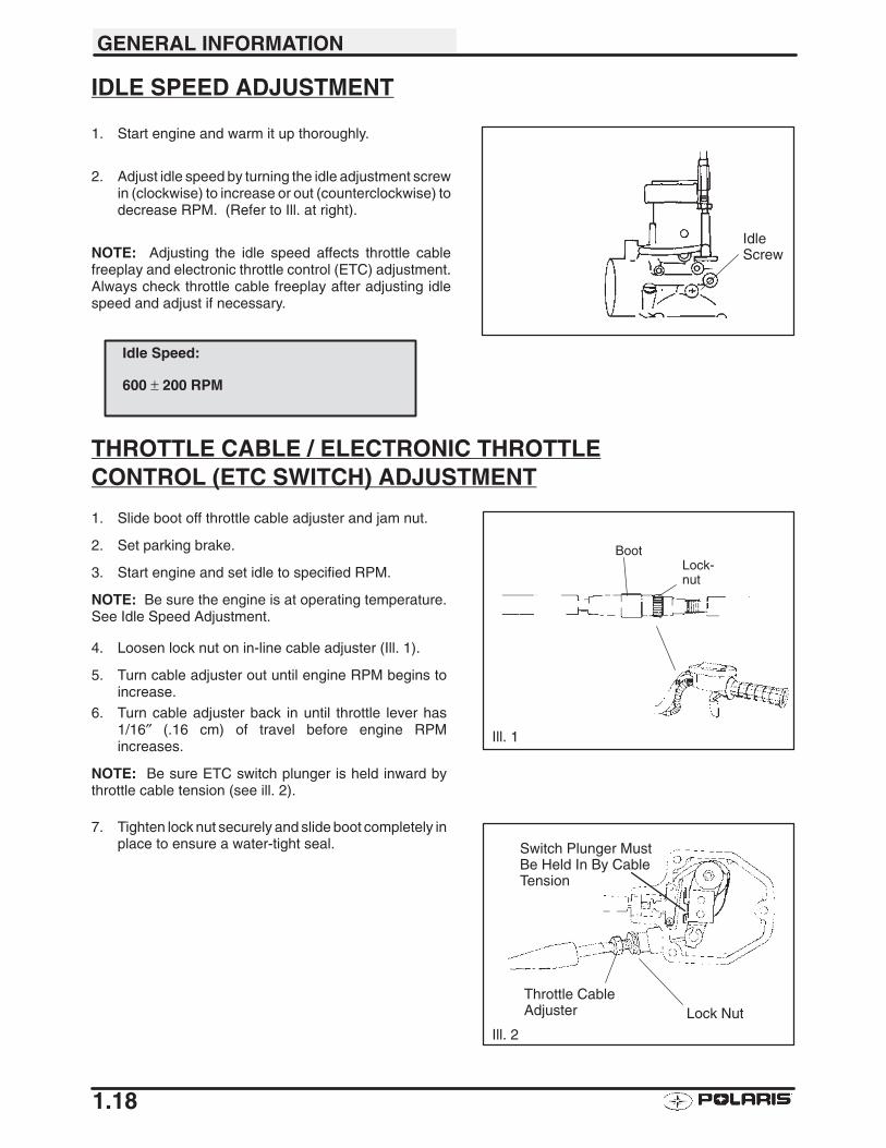
3. After the oil has drained completely, install a newsealing washer and install the drain plug. Torque to14 ft. lbs. (19.3 Nm).
4. Add the proper lubricant through the fill plug hole.Do not overfill.
5. Check for leaks.
Fill Plug
Specified Lubricant:Polaris Premium Synthetic Gearcase LubricantPN 2871477 (Gallon) PN 2871478 (12 oz..)
Capacity: 10 fl.oz. / 300 ml. . . . . Operating Range: 1/2″ (12.7 mm) belowtip of dipstick.
Drain Plug Torque:
14 ft. lbs. (19.4 Nm)
TRANSMISSION SPECIFICATIONS
Vent Hose
Drain Plug
GENERAL INFORMATION
1.17
THROTTLE OPERATIONCheck for smooth throttle opening and closing in all han-dlebar positions. Throttle lever operation should besmooth and lever must return freely without binding.
1. Start the engine and let it idle.
2. Turn handlebars from full right to full left. If idle speedincreases at any point in the turning range, inspectthrottle cable routing and condition.
3. Replace the throttle cable if worn, kinked, or damaged.
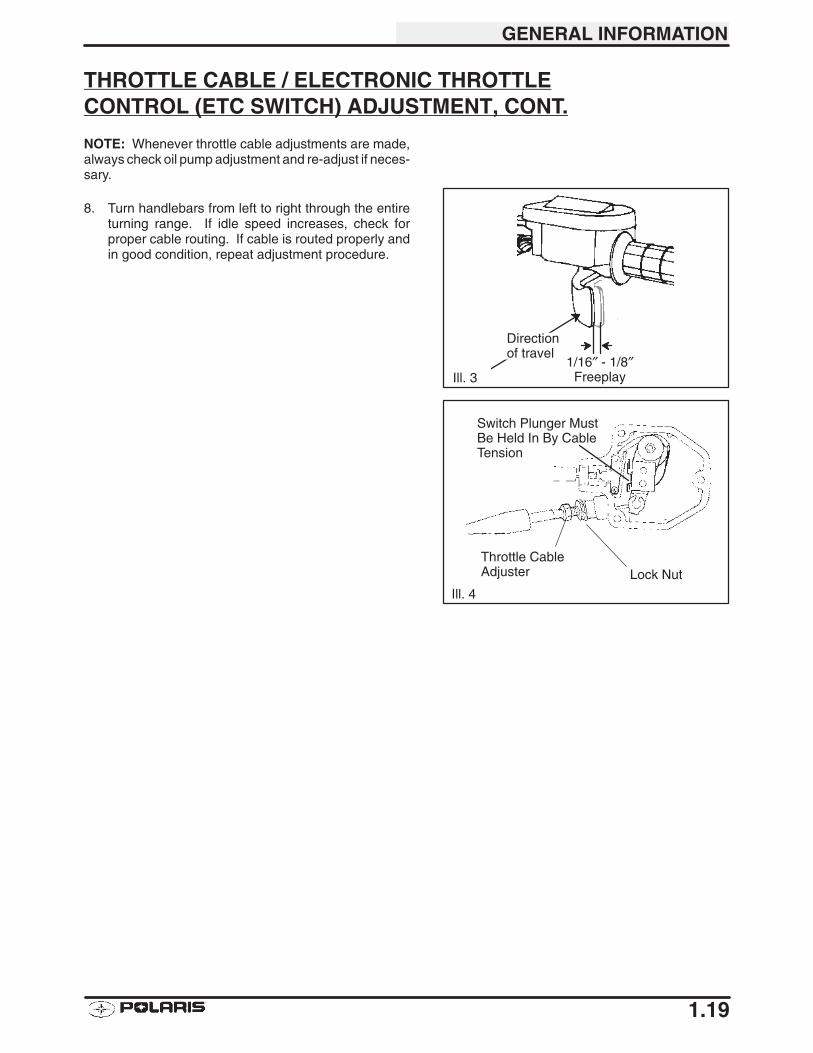
AIR SCREW ADJUSTMENT
1. Turn carburetor air screw in (clockwise) until lightlyseated. Back screw out the specified number of turns.
2. Warm up the engine to operating temperature (about10 minutes).
3. Set idle speed to 600 RPM.
NOTE: Adjusting the air screw may affect idle speed.Always check throttle cable freeplay after adjusting idlespeed and adjust if necessary.
4. Turn the screw in (to richen) or out (to lean) themixture. Adjust air screw for best throttle responseand smooth idle.
5. Re-adjust idle speed if necessary.
Air Screw Adjustment:
1.5 Turns Out from Lightly Seated
Idle SpeedScrew
Air Screw
GENERAL INFORMATION
1.18
IDLE SPEED ADJUSTMENT
1. Start engine and warm it up thoroughly.
2. Adjust idle speed by turning the idle adjustment screwin (clockwise) to increase or out (counterclockwise) todecrease RPM. (Refer to Ill. at right).
NOTE: Adjusting the idle speed affects throttle cablefreeplay and electronic throttle control (ETC) adjustment.Always check throttle cable freeplay after adjusting idlespeed and adjust if necessary.
THROTTLE CABLE / ELECTRONIC THROTTLECONTROL (ETC SWITCH) ADJUSTMENT
1. Slide boot off throttle cable adjuster and jam nut.
2. Set parking brake.
3. Start engine and set idle to specified RPM.
NOTE: Be sure the engine is at operating temperature.See Idle Speed Adjustment.
4. Loosen lock nut on in-line cable adjuster (Ill. 1).
5. Turn cable adjuster out until engine RPM begins toincrease.
6. Turn cable adjuster back in until throttle lever has1/16″ (.16 cm) of travel before engine RPMincreases.
NOTE: Be sure ETC switch plunger is held inward bythrottle cable tension (see ill. 2).
7. Tighten lock nut securely and slide boot completely inplace to ensure a water-tight seal.
Idle Speed:
600 ± 200 RPM
IdleScrew
BootLock-nut
Ill. 1
Switch Plunger MustBe Held In By CableTension
Ill. 2
Throttle CableAdjuster Lock Nut
GENERAL INFORMATION
1.19
THROTTLE CABLE / ELECTRONIC THROTTLECONTROL (ETC SWITCH) ADJUSTMENT, CONT.
NOTE: Whenever throttle cable adjustments are made,always check oil pump adjustment and re-adjust if neces-sary.
8. Turn handlebars from left to right through the entireturning range. If idle speed increases, check forproper cable routing. If cable is routed properly andin good condition, repeat adjustment procedure.
1/16″ - 1/8″Freeplay
Directionof travel
Ill. 3
Switch Plunger MustBe Held In By CableTension
Ill. 4
Throttle CableAdjuster Lock Nut
GENERAL INFORMATION
1.20
OIL PUMP ADJUSTMENT PROCEDURE
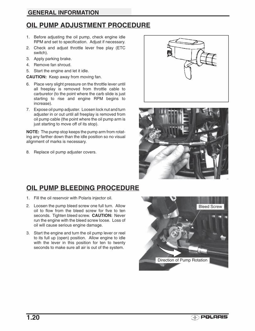
1. Before adjusting the oil pump, check engine idleRPM and set to specification. Adjust if necessary.
2. Check and adjust throttle lever free play (ETCswitch).
3. Apply parking brake.
4. Remove fan shroud.
5. Start the engine and let it idle.
CAUTION: Keep away from moving fan.
6. Place very slight pressure on the throttle lever untilall freeplay is removed from throttle cable tocarburetor (to the point where the carb slide is juststarting to rise and engine RPM begins toincrease).
7. Expose oil pump adjuster. Loosen lock nut and turnadjuster in or out until all freeplay is removed fromoil pump cable (the point where the oil pump arm isjust starting to move off of its stop).
NOTE: The pump stop keeps the pump arm from rotat-ing any farther down than the idle position so no visualalignment of marks is necessary.
8. Replace oil pump adjuster covers.
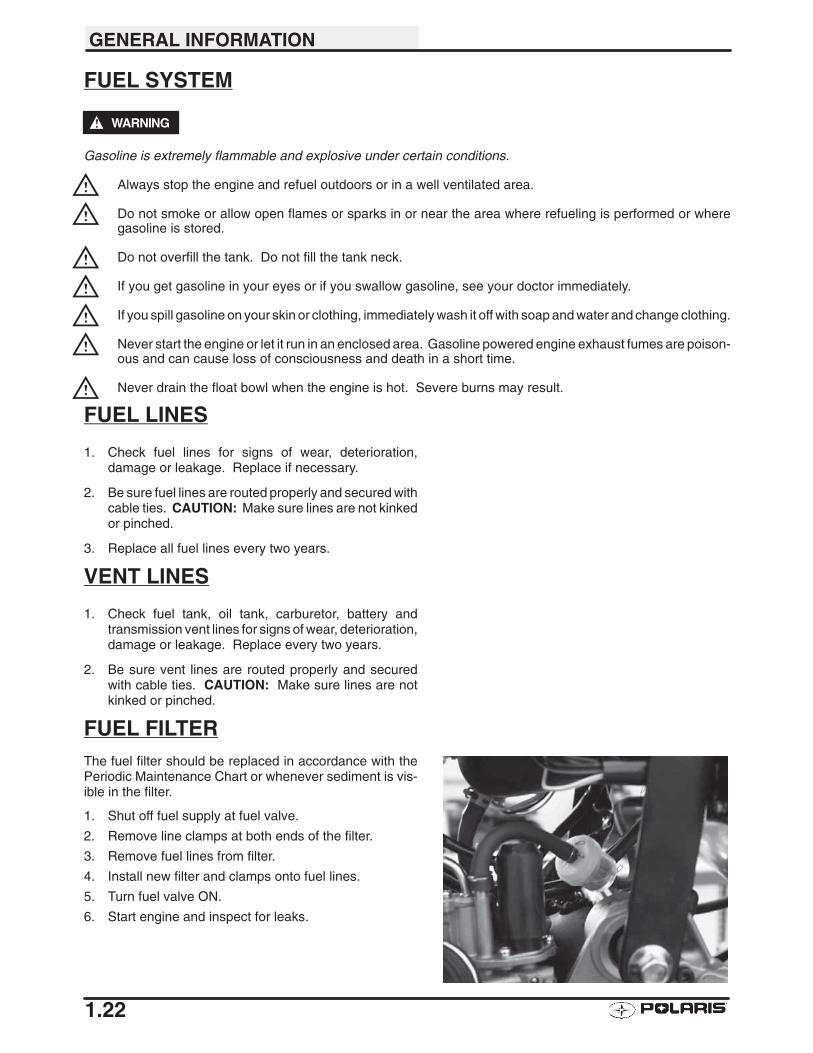
OIL PUMP BLEEDING PROCEDURE1. Fill the oil reservoir with Polaris injector oil.
2. Loosen the pump bleed screw one full turn. Allowoil to flow from the bleed screw for five to tenseconds. Tighten bleed screw. CAUTION: Neverrun the engine with the bleed screw loose. Loss ofoil will cause serious engine damage.
3. Start the engine and turn the oil pump lever or reelto its full up (open) position. Allow engine to idlewith the lever in this position for ten to twentyseconds to make sure all air is out of the system.
Bleed Screw
Direction of Pump Rotation

GENERAL INFORMATION
1.21
OIL PUMP TROUBLESHOOTING PROCEDURE
To verify oil delivery to engine, proceed as follows:
1. Premix fuel in tank at a 40:1 fuel/oil ratio.
2. With the oil reservoir full and the pump bled, removethe oil delivery line from the intake manifold.
3. Test the oil delivery check valve with a low pressurepump and gauge.
4. Start engine and lift oil pump lever to full open position.
5. Oil should pulse from the delivery line every few seconds.If it does not, suspect one of the following:
A. Oil line plugged
B. Oil tank vent line restricted
C. Oil line leaking or blocked
D. Faulty oil pump or drive mechanism
E. Air in oil Lines
F. Insufficient/Improper oil in oil tank
GENERAL INFORMATION
1.22
FUEL SYSTEM
WARNING
Gasoline is extremely flammable and explosive under certain conditions.
Always stop the engine and refuel outdoors or in a well ventilated area.
Do not smoke or allow open flames or sparks in or near the area where refueling is performed or wheregasoline is stored.
Do not overfill the tank. Do not fill the tank neck.
If you get gasoline in your eyes or if you swallow gasoline, see your doctor immediately.
If you spill gasoline on your skin or clothing, immediately wash it off with soap and water and change clothing.
Never start the engine or let it run in an enclosed area. Gasoline powered engine exhaust fumes are poison-ous and can cause loss of consciousness and death in a short time.
Never drain the float bowl when the engine is hot. Severe burns may result.
FUEL LINES
1. Check fuel lines for signs of wear, deterioration,damage or leakage. Replace if necessary.
2. Be sure fuel lines are routed properly and secured withcable ties. CAUTION: Make sure lines are not kinkedor pinched.
3. Replace all fuel lines every two years.
VENT LINES
1. Check fuel tank, oil tank, carburetor, battery andtransmission vent lines for signs of wear, deterioration,damage or leakage. Replace every two years.
2. Be sure vent lines are routed properly and securedwith cable ties. CAUTION: Make sure lines are notkinked or pinched.
FUEL FILTERThe fuel filter should be replaced in accordance with thePeriodic Maintenance Chart or whenever sediment is vis-ible in the filter.
1. Shut off fuel supply at fuel valve.
2. Remove line clamps at both ends of the filter.
3. Remove fuel lines from filter.
4. Install new filter and clamps onto fuel lines.
5. Turn fuel valve ON.
6. Start engine and inspect for leaks.
GENERAL INFORMATION
1.23
CARBURETOR DRAINING
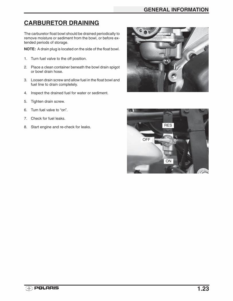
The carburetor float bowl should be drained periodically toremove moisture or sediment from the bowl, or before ex-tended periods of storage.
NOTE: A drain plug is located on the side of the float bowl.
1. Turn fuel valve to the off position.
2. Place a clean container beneath the bowl drain spigotor bowl drain hose.
3. Loosen drain screw and allow fuel in the float bowl andfuel line to drain completely.
4. Inspect the drained fuel for water or sediment.
5. Tighten drain screw.
6. Turn fuel valve to “on”.
7. Check for fuel leaks.
8. Start engine and re-check for leaks.
OFF
RES
ON
GENERAL INFORMATION
1.24
COMPRESSION TEST
1. Remove spark plug and install compression tester.
2. Connect high tension lead to a good ground on engine.
3. Open throttle and crank engine until maximum reading is obtained (approximately 3-5 revolutions).
AIR FILTER SERVICE
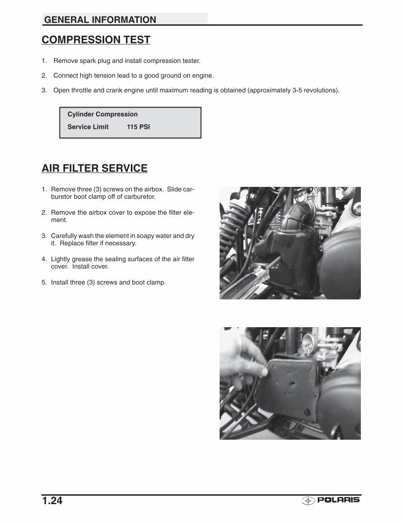
1. Remove three (3) screws on the airbox. Slide car-buretor boot clamp off of carburetor.
2. Remove the airbox cover to expose the filter ele-ment.
3. Carefully wash the element in soapy water and dryit. Replace filter if necessary.
4. Lightly grease the sealing surfaces of the air filtercover. Install cover.
5. Install three (3) screws and boot clamp.
Cylinder Compression
Service Limit 115 PSI
GENERAL INFORMATION
1.25
WHEELS
Inspect all wheels for runout or damage. Check wheel boltsand ensure they are tight. Do not over tighten the wheelbolts.
WHEEL, HUB, AND SPINDLE TORQUE TABLE
Item Specification
Front Wheel Bolts 22-29 Ft. Lbs. (30-40 Nm)
Rear Wheel Bolts 22-29 Ft. Lbs. (30-40 Nm)
Front Spindle Nut 42-45 Ft. Lbs. (58-62 Nm)
Rear Hub Retaining Nut 78-81 Ft. Lbs. (108-112 Nm)
WHEEL REMOVAL FRONT OR REAR1. Stop the engine and lock the parking brake.
2. Loosen the wheel bolts slightly.3. Elevate the side of the vehicle by placing a
suitable stand under the footrest frame.
4. Remove the wheel nuts and remove the wheel.
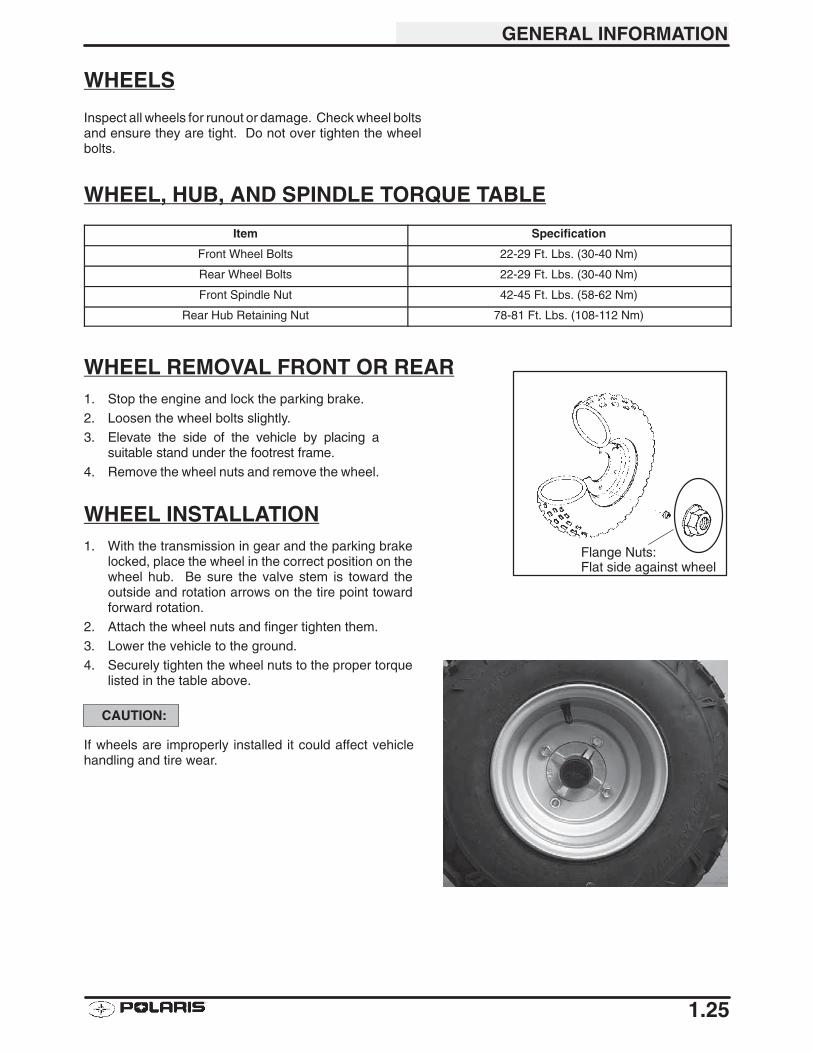
WHEEL INSTALLATION1. With the transmission in gear and the parking brake
locked, place the wheel in the correct position on thewheel hub. Be sure the valve stem is toward theoutside and rotation arrows on the tire point towardforward rotation.
2. Attach the wheel nuts and finger tighten them.
3. Lower the vehicle to the ground.4. Securely tighten the wheel nuts to the proper torque
listed in the table above.
CAUTION:
If wheels are improperly installed it could affect vehiclehandling and tire wear.
Flange Nuts:Flat side against wheel
GENERAL INFORMATION
1.26
TIRE PRESSURE
Tire Pressure Inspection (PSI - Cold)
Front Rear
2 2
TIRE INSPECTION
CAUTION:
Maintain proper tire pressure. Refer to the tire pressurewarning decal applied to the vehicle.
Improper tire inflation may affect ATV maneuverability.
When replacing a tire always use original equipment sizeand type.
The use of non-standard size or type tires may affect ATVhandling.
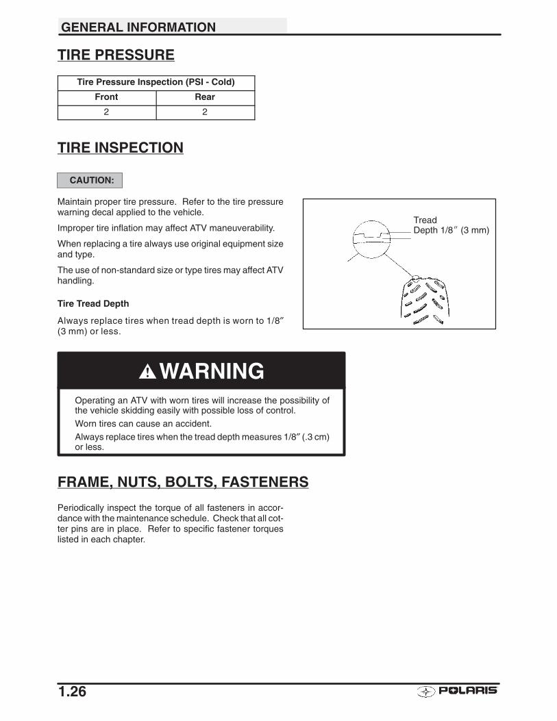
Tire Tread Depth
Always replace tires when tread depth is worn to 1/8″(3 mm) or less.
WARNINGOperating an ATV with worn tires will increase the possibility ofthe vehicle skidding easily with possible loss of control.
Worn tires can cause an accident.
Always replace tires when the tread depth measures 1/8″ (.3 cm)or less.
FRAME, NUTS, BOLTS, FASTENERS
Periodically inspect the torque of all fasteners in accor-dance with the maintenance schedule. Check that all cot-ter pins are in place. Refer to specific fastener torqueslisted in each chapter.
TreadDepth 1/8� (3 mm)
GENERAL INFORMATION
1.27
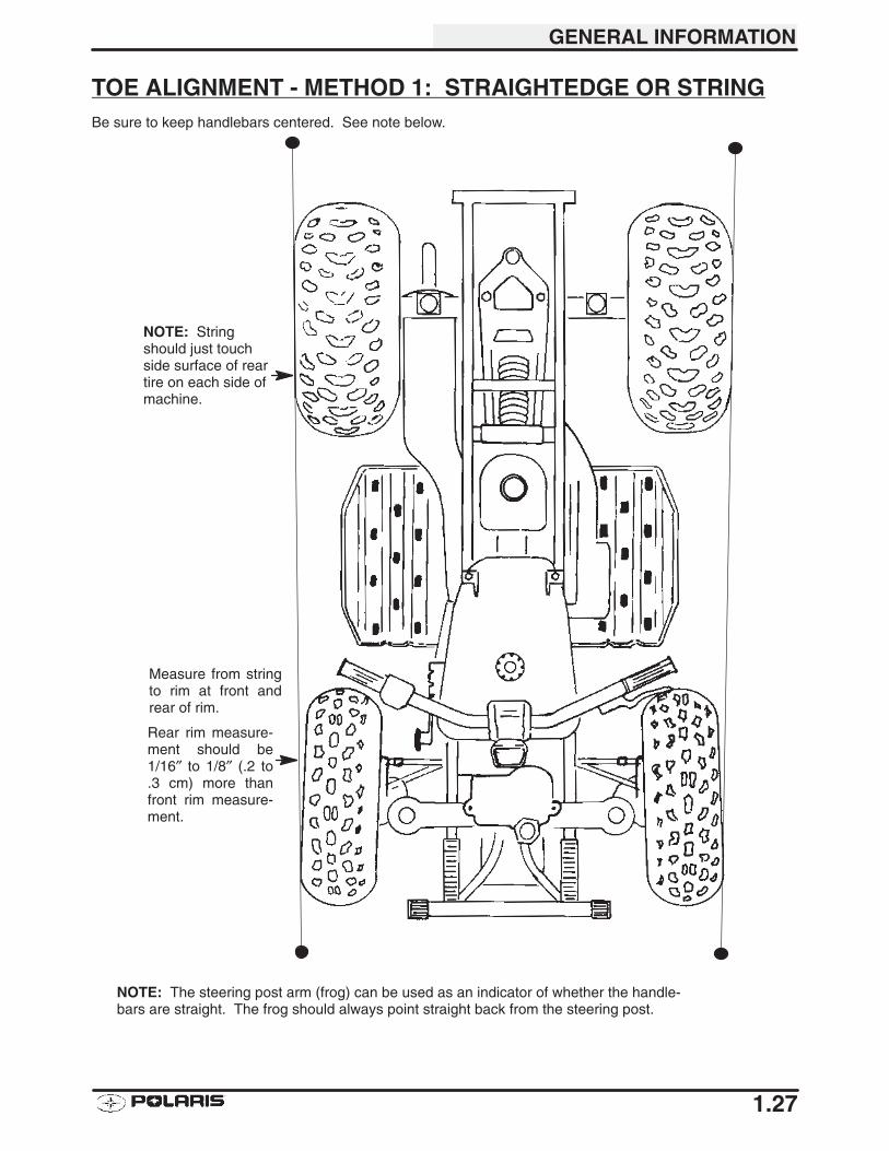
TOE ALIGNMENT - METHOD 1: STRAIGHTEDGE OR STRINGBe sure to keep handlebars centered. See note below.
Measure from stringto rim at front andrear of rim.
NOTE: Stringshould just touchside surface of reartire on each side ofmachine.
NOTE: The steering post arm (frog) can be used as an indicator of whether the handle-bars are straight. The frog should always point straight back from the steering post.
Rear rim measure-ment should be1/16″ to 1/8″ (.2 to.3 cm) more thanfront rim measure-ment.
GENERAL INFORMATION
1.28
TOE ALIGNMENT - METHOD 2 CHALK
1. Place machine on a smooth level surface.
2. Set handlebars in a straight ahead position andsecure handlebars in this position. NOTE: Thesteering frog can be used as an indicator of whetherthe handlebars are straight. The frog should alwayspoint straight back from the steering post.
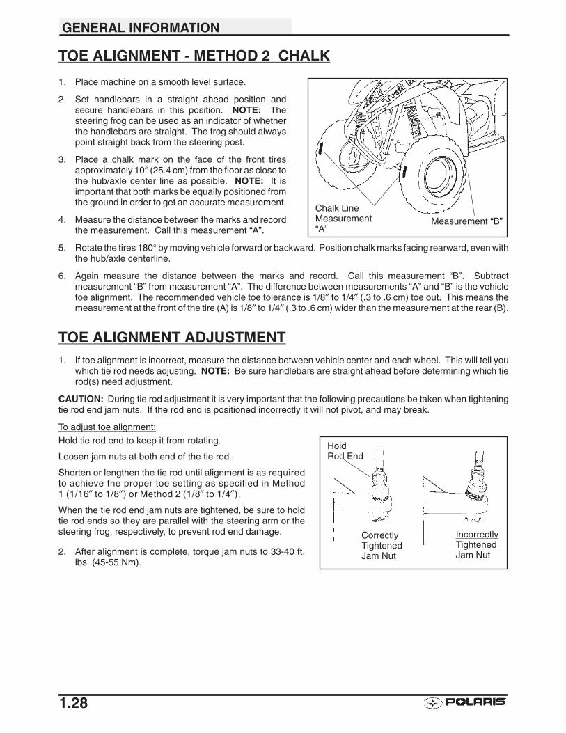
3. Place a chalk mark on the face of the front tiresapproximately 10″ (25.4 cm) from the floor as close tothe hub/axle center line as possible. NOTE: It isimportant that both marks be equally positioned fromthe ground in order to get an accurate measurement.
4. Measure the distance between the marks and recordthe measurement. Call this measurement “A”.
5. Rotate the tires 180° by moving vehicle forward or backward. Position chalk marks facing rearward, even withthe hub/axle centerline.
6. Again measure the distance between the marks and record. Call this measurement “B”. Subtractmeasurement “B” from measurement “A”. The difference between measurements “A” and “B” is the vehicletoe alignment. The recommended vehicle toe tolerance is 1/8″ to 1/4″ (.3 to .6 cm) toe out. This means themeasurement at the front of the tire (A) is 1/8″ to 1/4″ (.3 to .6 cm) wider than the measurement at the rear (B).
TOE ALIGNMENT ADJUSTMENT1. If toe alignment is incorrect, measure the distance between vehicle center and each wheel. This will tell you
which tie rod needs adjusting. NOTE: Be sure handlebars are straight ahead before determining which tierod(s) need adjustment.
CAUTION: During tie rod adjustment it is very important that the following precautions be taken when tighteningtie rod end jam nuts. If the rod end is positioned incorrectly it will not pivot, and may break.
To adjust toe alignment:
Hold tie rod end to keep it from rotating.
Loosen jam nuts at both end of the tie rod.
Shorten or lengthen the tie rod until alignment is as requiredto achieve the proper toe setting as specified in Method1 (1/16″ to 1/8″) or Method 2 (1/8″ to 1/4″).
When the tie rod end jam nuts are tightened, be sure to holdtie rod ends so they are parallel with the steering arm or thesteering frog, respectively, to prevent rod end damage.
2. After alignment is complete, torque jam nuts to 33-40 ft.lbs. (45-55 Nm).
Chalk LineMeasurement“A”
Measurement “B”
IncorrectlyTightenedJam Nut
CorrectlyTightenedJam Nut
HoldRod End
2
CHAPTER 2ENGINE
Torque Specifications 2.1. . . . . . . . . . . . . . . . . . . . . . . . . . . . Special Tools, Engine 2.1. . . . . . . . . . . . . . . . . . . . . . . . . . . . Engine Installation Notes 2.2. . . . . . . . . . . . . . . . . . . . . . . . . Engine Disassembly 2.3-2.12. . . . . . . . . . . . . . . . . . . . . . . . . . . . . Engine Inspection 2.13-2.15. . . . . . . . . . . . . . . . . . . . . . . . . . . . . . . Cylinder Honing 2.16. . . . . . . . . . . . . . . . . . . . . . . . . . . . . . . . . Crankshaft Runout Inspection 2.17. . . . . . . . . . . . . . . . . . . . . Engine Assembly 2.18-2.16. . . . . . . . . . . . . . . . . . . . . . . . . . . . . . . . Spark Plug Fouling 2.27. . . . . . . . . . . . . . . . . . . . . . . . . . . . . . Engine Troubleshooting 2.28-2.29. . . . . . . . . . . . . . . . . . . . . . . . . .

ENGINE
2.1
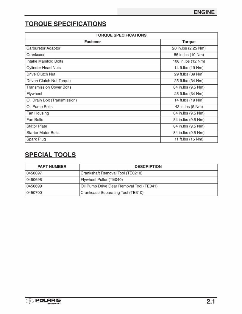
TORQUE SPECIFICATIONS
TORQUE SPECIFICATIONS
Fastener Torque
Carburetor Adaptor 20 in.lbs (2.25 Nm)
Crankcase 86 in.lbs (10 Nm)
Intake Manifold Bolts 108 in.lbs (12 Nm)
Cylinder Head Nuts 14 ft.lbs (19 Nm)
Drive Clutch Nut 29 ft.lbs (39 Nm)
Driven Clutch Nut Torque 25 ft.lbs (34 Nm)
Transmission Cover Bolts 84 in.lbs (9.5 Nm)
Flywheel 25 ft.lbs (34 Nm)
Oil Drain Bolt (Transmission) 14 ft.lbs (19 Nm)
Oil Pump Bolts 43 in.lbs (5 Nm)
Fan Housing 84 in.lbs (9.5 Nm)
Fan Bolts 84 in.lbs (9.5 Nm)
Stator Plate 84 in.lbs (9.5 Nm)
Starter Motor Bolts 84 in.lbs (9.5 Nm)
Spark Plug 11 ft.lbs (15 Nm)
SPECIAL TOOLS
PART NUMBER DESCRIPTION
0450697 Crankshaft Removal Tool (TE0210)
0450698 Flywheel Puller (TE040)
0450699 Oil Pump Drive Gear Removal Tool (TE041)
0450700 Crankcase Separating Tool (TE310)
ENGINE
2.2
ENGINE INSTALLATION NOTES
General Items1. Install previously removed components using new gaskets, seals, and fasteners where applicable.
2. Perform regular checks on fluid levels, controls, and all important areas on the vehicle as outlined in the dailypre-ride inspection checklist.
Exhaust1. Replace exhaust gaskets. Seal connections with high temp silicone sealant.
2. Check to be sure all springs are in good condition.
Engine Break In Period
Engine Break-In Period is defined as the first 10 hours of engine operation, or 2 full tanks of fuel.1. Use only Polaris Premium 2 cycle engine oil. Never substitute or mix oil brands. Serious engine damage can
result.
2. Use fuel with a minimum octane of 87 (R+M)/2 method.
ENGINE
2.3
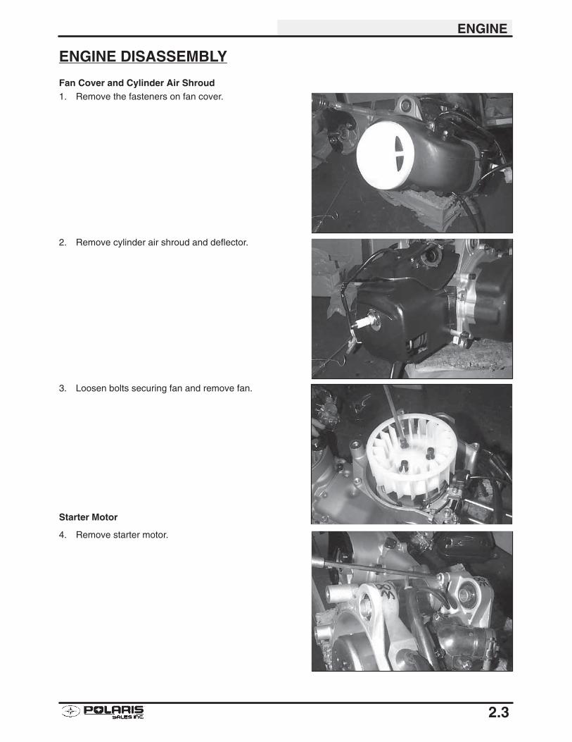
ENGINE DISASSEMBLY
Fan Cover and Cylinder Air Shroud1. Remove the fasteners on fan cover.
2. Remove cylinder air shroud and deflector.
3. Loosen bolts securing fan and remove fan.
Starter Motor
4. Remove starter motor.
ENGINE
2.4
ENGINE DISASSEMBLY, CONT.
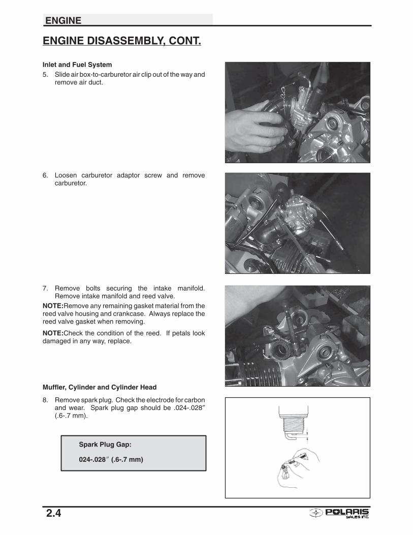
Inlet and Fuel System5. Slide air box-to-carburetor air clip out of the way and
remove air duct.
6. Loosen carburetor adaptor screw and removecarburetor.
7. Remove bolts securing the intake manifold.Remove intake manifold and reed valve.
NOTE:Remove any remaining gasket material from thereed valve housing and crankcase. Always replace thereed valve gasket when removing.
NOTE:Check the condition of the reed. If petals lookdamaged in any way, replace.
Muffler, Cylinder and Cylinder Head
8. Remove spark plug. Check the electrode for carbonand wear. Spark plug gap should be .024-.028″(.6-.7 mm).
Spark Plug Gap:
024-.028� (.6-.7 mm)
ENGINE
2.5
ENGINE DISASSEMBLY, CONT.
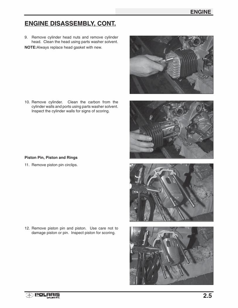
9. Remove cylinder head nuts and remove cylinderhead. Clean the head using parts washer solvent.
NOTE:Always replace head gasket with new.
10. Remove cylinder. Clean the carbon from thecylinder walls and ports using parts washer solvent.Inspect the cylinder walls for signs of scoring.
Piston Pin, Piston and Rings
11. Remove piston pin circlips.
12. Remove piston pin and piston. Use care not todamage piston or pin. Inspect piston for scoring.
ENGINE
2.6
ENGINE DISASSEMBLY, CONT.
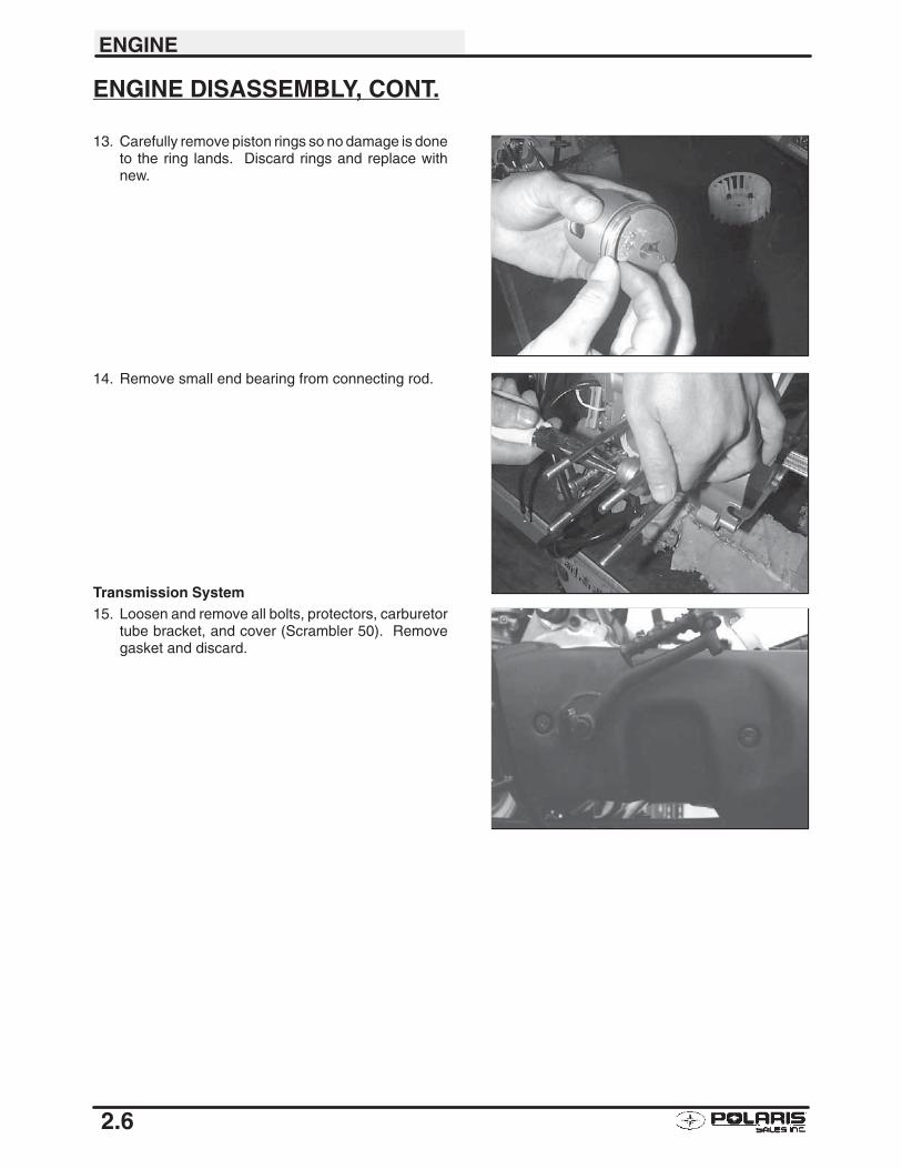
13. Carefully remove piston rings so no damage is doneto the ring lands. Discard rings and replace withnew.
14. Remove small end bearing from connecting rod.
Transmission System15. Loosen and remove all bolts, protectors, carburetor
tube bracket, and cover (Scrambler 50). Removegasket and discard.
ENGINE
2.7
ENGINE DISASSEMBLY, CONT.
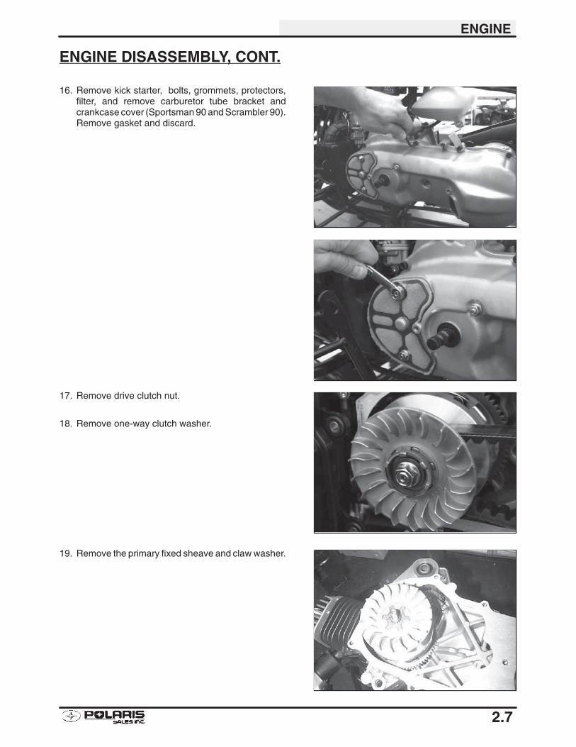
16. Remove kick starter, bolts, grommets, protectors,filter, and remove carburetor tube bracket andcrankcase cover (Sportsman 90 and Scrambler 90).Remove gasket and discard.
17. Remove drive clutch nut.
18. Remove one-way clutch washer.
19. Remove the primary fixed sheave and claw washer.
ENGINE
2.8
ENGINE DISASSEMBLY, CONT.
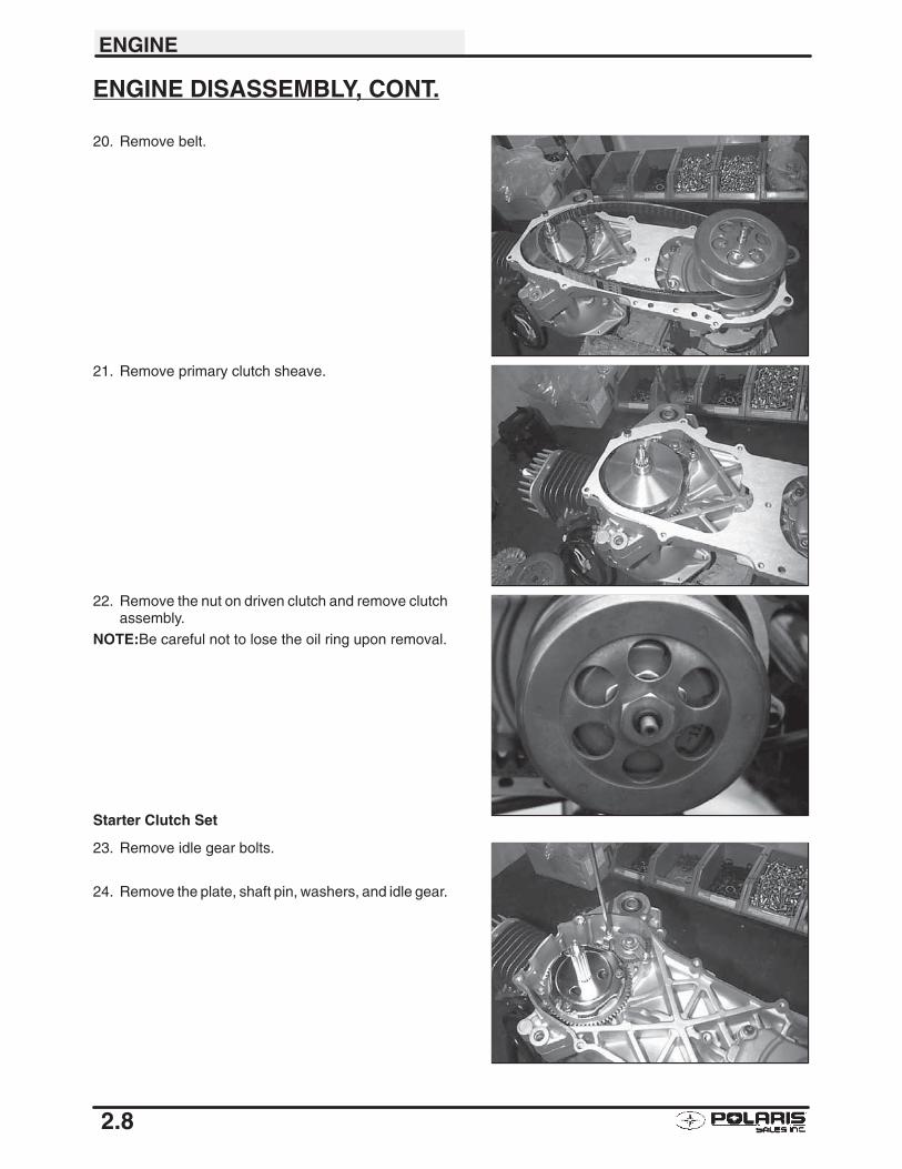
20. Remove belt.
21. Remove primary clutch sheave.
22. Remove the nut on driven clutch and remove clutchassembly.
NOTE:Be careful not to lose the oil ring upon removal.
Starter Clutch Set
23. Remove idle gear bolts.
24. Remove the plate, shaft pin, washers, and idle gear.
ENGINE
2.9
ENGINE DISASSEMBLY, CONT.
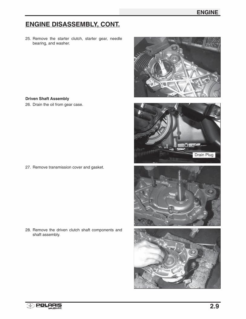
25. Remove the starter clutch, starter gear, needlebearing, and washer.
Driven Shaft Assembly26. Drain the oil from gear case.
27. Remove transmission cover and gasket.
28. Remove the driven clutch shaft components andshaft assembly.
Drain Plug
ENGINE
2.10
ENGINE DISASSEMBLY, CONT.
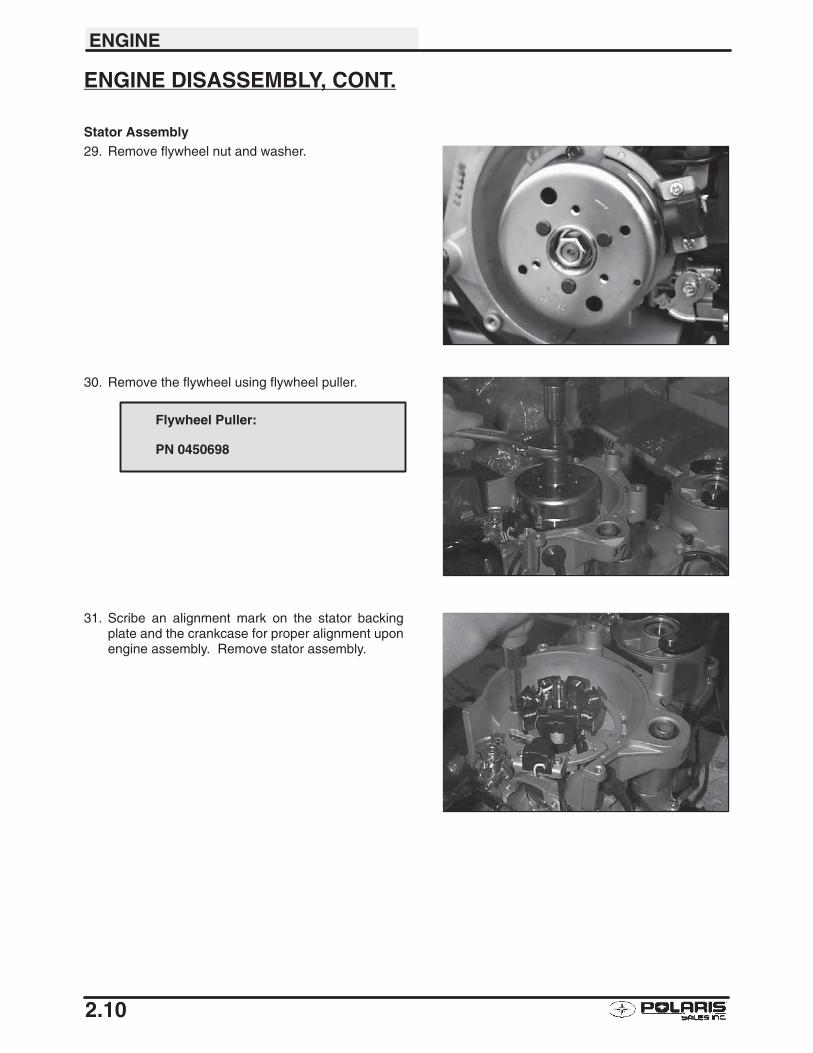
Stator Assembly29. Remove flywheel nut and washer.
30. Remove the flywheel using flywheel puller.
31. Scribe an alignment mark on the stator backingplate and the crankcase for proper alignment uponengine assembly. Remove stator assembly.
Flywheel Puller:
PN 0450698
ENGINE
2.11
ENGINE DISASSEMBLY, CONT.
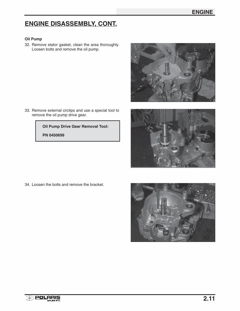
Oil Pump32. Remove stator gasket, clean the area thoroughly.
Loosen bolts and remove the oil pump.
33. Remove external circlips and use a special tool toremove the oil pump drive gear.
34. Loosen the bolts and remove the bracket.
Oil Pump Drive Gear Removal Tool:
PN 0450699
ENGINE
2.12
ENGINE DISASSEMBLY, CONT.
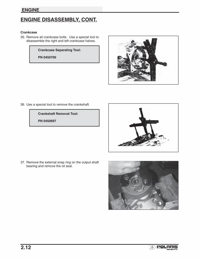
Crankcase35. Remove all crankcase bolts. Use a special tool to
disassemble the right and left crankcase halves.
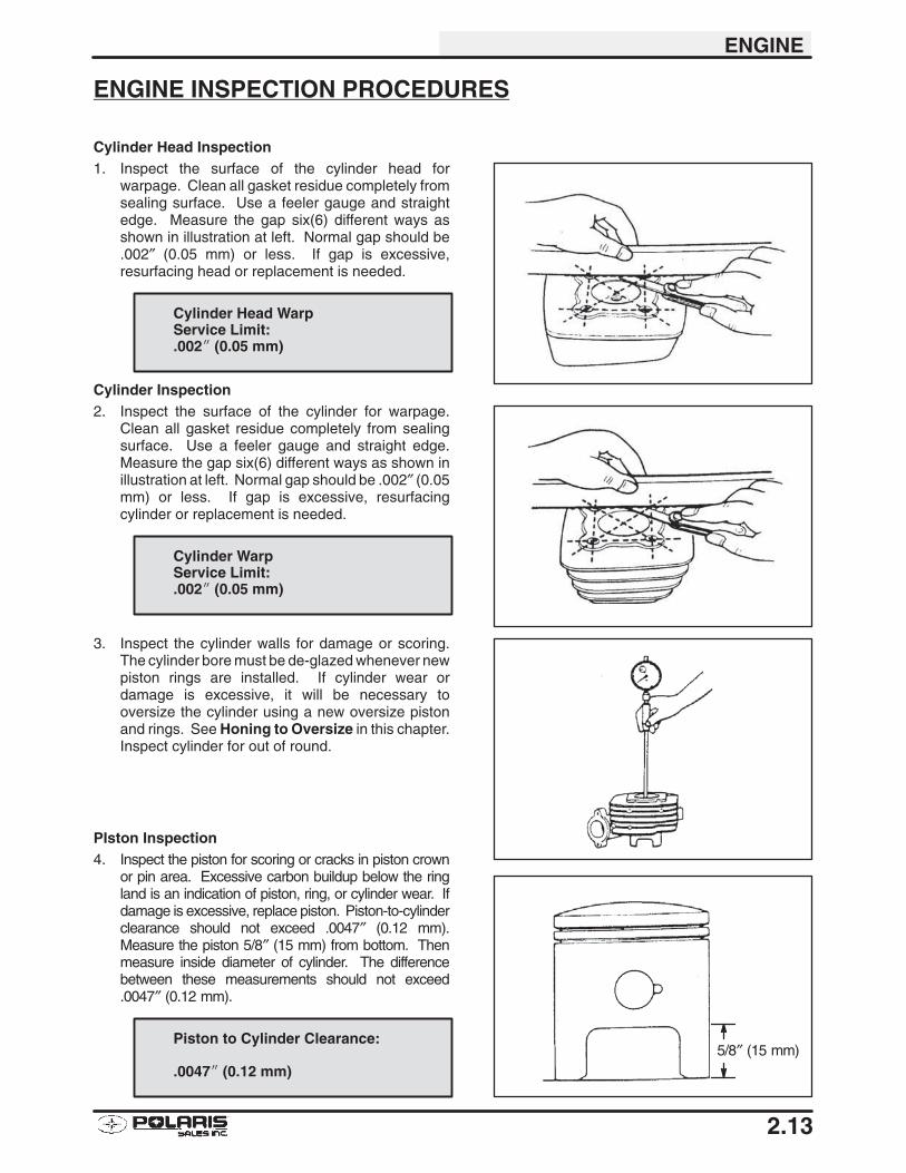
36. Use a special tool to remove the crankshaft.
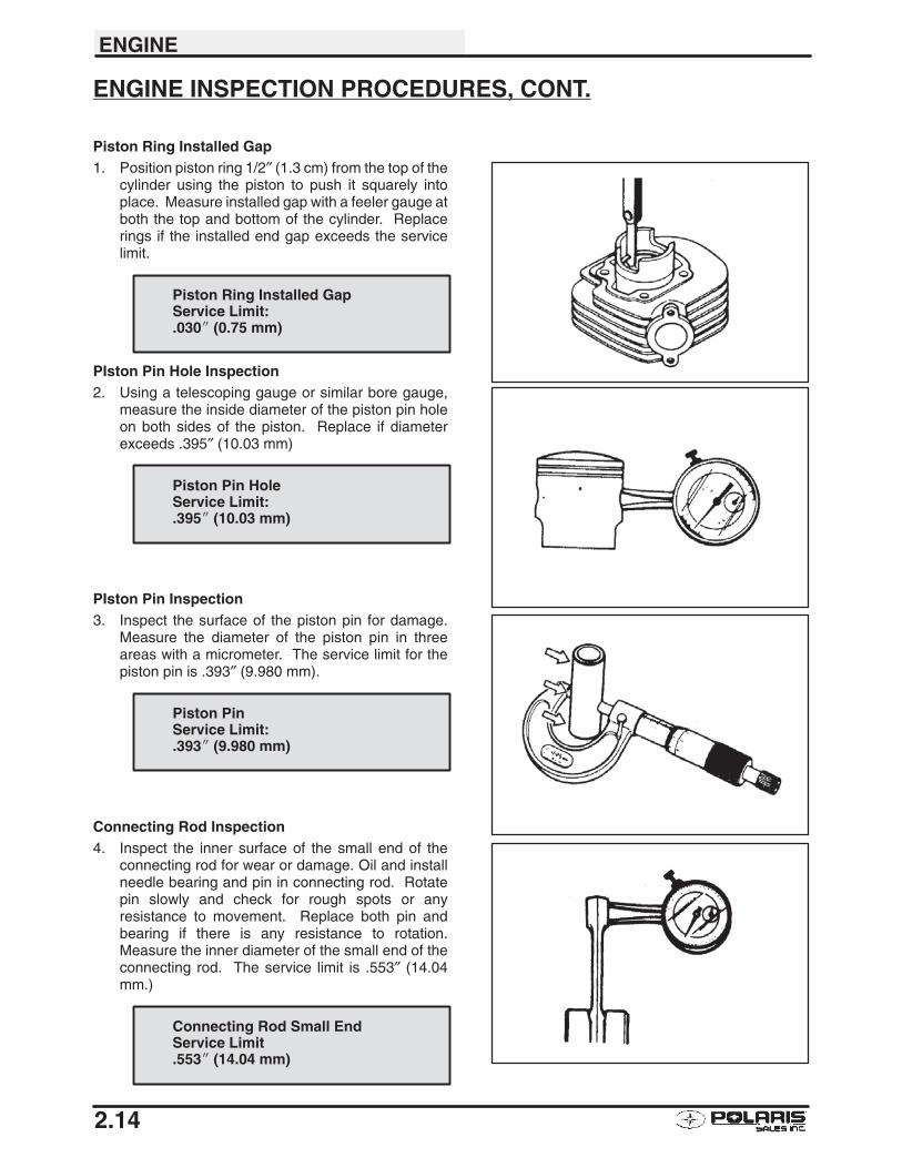
37. Remove the external snap ring on the output shaftbearing and remove the oil seal.
Crankcase Separating Tool:
PN 0450700
Crankshaft Removal Tool:
PN 0450697
ENGINE
2.13
ENGINE INSPECTION PROCEDURES
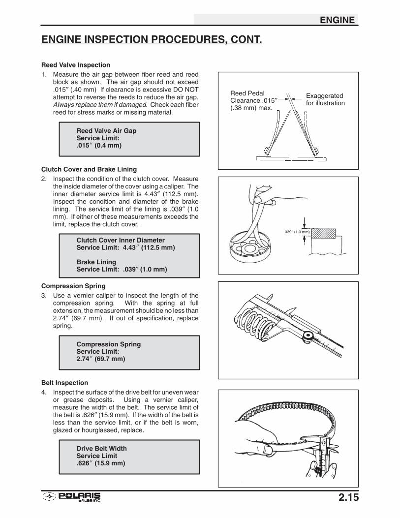
Cylinder Head Inspection1. Inspect the surface of the cylinder head for
warpage. Clean all gasket residue completely fromsealing surface. Use a feeler gauge and straightedge. Measure the gap six(6) different ways asshown in illustration at left. Normal gap should be.002″ (0.05 mm) or less. If gap is excessive,resurfacing head or replacement is needed.
Cylinder Inspection2. Inspect the surface of the cylinder for warpage.
Clean all gasket residue completely from sealingsurface. Use a feeler gauge and straight edge.Measure the gap six(6) different ways as shown inillustration at left. Normal gap should be .002″ (0.05mm) or less. If gap is excessive, resurfacingcylinder or replacement is needed.
3. Inspect the cylinder walls for damage or scoring.The cylinder bore must be de-glazed whenever newpiston rings are installed. If cylinder wear ordamage is excessive, it will be necessary tooversize the cylinder using a new oversize pistonand rings. See Honing to Oversize in this chapter.Inspect cylinder for out of round.
PIston Inspection4. Inspect the piston for scoring or cracks in piston crown
or pin area. Excessive carbon buildup below the ringland is an indication of piston, ring, or cylinder wear. Ifdamage is excessive, replace piston. Piston-to-cylinderclearance should not exceed .0047″ (0.12 mm).Measure the piston 5/8″ (15 mm) from bottom. Thenmeasure inside diameter of cylinder. The differencebetween these measurements should not exceed.0047″ (0.12 mm).
Cylinder Head WarpService Limit:.002� (0.05 mm)
Cylinder WarpService Limit:.002� (0.05 mm)
5/8″ (15 mm)Piston to Cylinder Clearance:
.0047� (0.12 mm)
ENGINE
2.14
ENGINE INSPECTION PROCEDURES, CONT.
Piston Ring Installed Gap1. Position piston ring 1/2″ (1.3 cm) from the top of the
cylinder using the piston to push it squarely intoplace. Measure installed gap with a feeler gauge atboth the top and bottom of the cylinder. Replacerings if the installed end gap exceeds the servicelimit.
PIston Pin Hole Inspection2. Using a telescoping gauge or similar bore gauge,
measure the inside diameter of the piston pin holeon both sides of the piston. Replace if diameterexceeds .395″ (10.03 mm)
PIston Pin Inspection3. Inspect the surface of the piston pin for damage.
Measure the diameter of the piston pin in threeareas with a micrometer. The service limit for thepiston pin is .393″ (9.980 mm).
Connecting Rod Inspection4. Inspect the inner surface of the small end of the
connecting rod for wear or damage. Oil and installneedle bearing and pin in connecting rod. Rotatepin slowly and check for rough spots or anyresistance to movement. Replace both pin andbearing if there is any resistance to rotation.Measure the inner diameter of the small end of theconnecting rod. The service limit is .553″ (14.04mm.)
Piston Ring Installed GapService Limit:.030� (0.75 mm)
Piston Pin HoleService Limit:.395� (10.03 mm)
Piston PinService Limit:.393� (9.980 mm)
Connecting Rod Small EndService Limit.553� (14.04 mm)
ENGINE
2.15
ENGINE INSPECTION PROCEDURES, CONT.
Reed Valve Inspection1. Measure the air gap between fiber reed and reed
block as shown. The air gap should not exceed.015″ (.40 mm) If clearance is excessive DO NOTattempt to reverse the reeds to reduce the air gap.Always replace them if damaged. Check each fiberreed for stress marks or missing material.
Clutch Cover and Brake Lining2. Inspect the condition of the clutch cover. Measure
the inside diameter of the cover using a caliper. Theinner diameter service limit is 4.43″ (112.5 mm).Inspect the condition and diameter of the brakelining. The service limit of the lining is .039″ (1.0mm). If either of these measurements exceeds thelimit, replace the clutch cover.
Compression Spring3. Use a vernier caliper to inspect the length of the
compression spring. With the spring at fullextension, the measurement should be no less than2.74″ (69.7 mm). If out of specification, replacespring.
Belt Inspection4. Inspect the surface of the drive belt for uneven wear
or grease deposits. Using a vernier caliper,measure the width of the belt. The service limit ofthe belt is .626″ (15.9 mm). If the width of the belt isless than the service limit, or if the belt is worn,glazed or hourglassed, replace.
Reed PedalClearance .015″(.38 mm) max.
Exaggeratedfor illustration
Reed Valve Air GapService Limit:.015� (0.4 mm)
.039″ (1.0 mm)
Clutch Cover Inner DiameterService Limit: 4.43� (112.5 mm)
Brake LiningService Limit: .039″ (1.0 mm)
Compression SpringService Limit:2.74� (69.7 mm)
Drive Belt WidthService Limit.626� (15.9 mm)
ENGINE
2.16
CYLINDER HONE SELECTION/HONING PROCEDURESelecting a hone which will straighten as well as remove material from the cylinder is very important. Using acommon spring loaded finger type glaze breaker for honing is never advised. Polaris recommends using a rigidhone or arbor honing machine which also has the capability of oversizing.
Cylinders may be wet or dry honed depending upon the hone manufacturer’s recommendations. Wet honing re-moves more material faster and leaves a more distinct pattern in the bore.
CAUTION:
HONING TO OVERSIZEIf cylinder wear or damage is excessive, it will be nec-essary to oversize the cylinder using a new oversizepiston and rings. This may be accomplished by eitherboring the cylinder and then finish honing to the finalbore size, or by rough honing followed by finish honing.
For oversize honing always wet hone using honing oiland a coarse roughing stone. Measure the piston (seepiston measurement) and rough hone to the size of thepiston. Always leave .002 - .003″ (.05 - .07 mm) for fin-ish honing. Refer to piston-to-cylinder clearance spec-ifications on page 2.13 before honing. Complete thesizing with fine grit stones to provide the proper cross-hatch finish and required piston clearance.
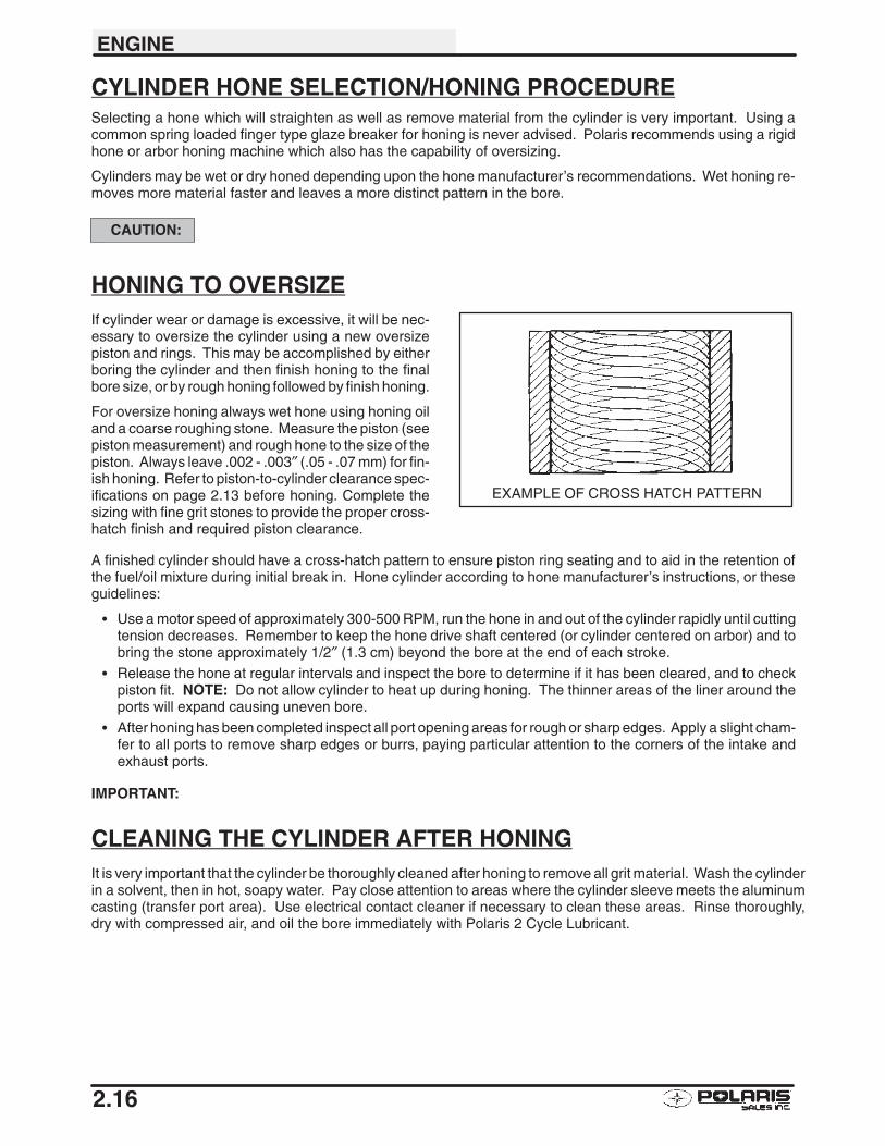
A finished cylinder should have a cross-hatch pattern to ensure piston ring seating and to aid in the retention ofthe fuel/oil mixture during initial break in. Hone cylinder according to hone manufacturer’s instructions, or theseguidelines:
� Use a motor speed of approximately 300-500 RPM, run the hone in and out of the cylinder rapidly until cuttingtension decreases. Remember to keep the hone drive shaft centered (or cylinder centered on arbor) and tobring the stone approximately 1/2″ (1.3 cm) beyond the bore at the end of each stroke.
� Release the hone at regular intervals and inspect the bore to determine if it has been cleared, and to checkpiston fit. NOTE: Do not allow cylinder to heat up during honing. The thinner areas of the liner around theports will expand causing uneven bore.
� After honing has been completed inspect all port opening areas for rough or sharp edges. Apply a slight cham-fer to all ports to remove sharp edges or burrs, paying particular attention to the corners of the intake andexhaust ports.
IMPORTANT:
CLEANING THE CYLINDER AFTER HONINGIt is very important that the cylinder be thoroughly cleaned after honing to remove all grit material. Wash the cylinderin a solvent, then in hot, soapy water. Pay close attention to areas where the cylinder sleeve meets the aluminumcasting (transfer port area). Use electrical contact cleaner if necessary to clean these areas. Rinse thoroughly,dry with compressed air, and oil the bore immediately with Polaris 2 Cycle Lubricant.
EXAMPLE OF CROSS HATCH PATTERN
ENGINE
2.17
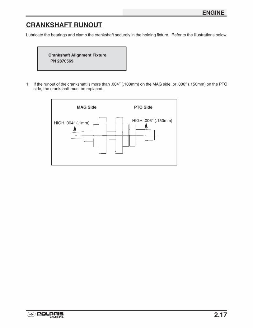
CRANKSHAFT RUNOUTLubricate the bearings and clamp the crankshaft securely in the holding fixture. Refer to the illustrations below.
1. If the runout of the crankshaft is more than .004″ (.100mm) on the MAG side, or .006″ (.150mm) on the PTOside, the crankshaft must be replaced.
Crankshaft Alignment FixturePN 2870569
HIGH .004″ (.1mm) HIGH .006″ (.150mm)
MAG Side PTO Side
ENGINE
2.18
ENGINE ASSEMBLY
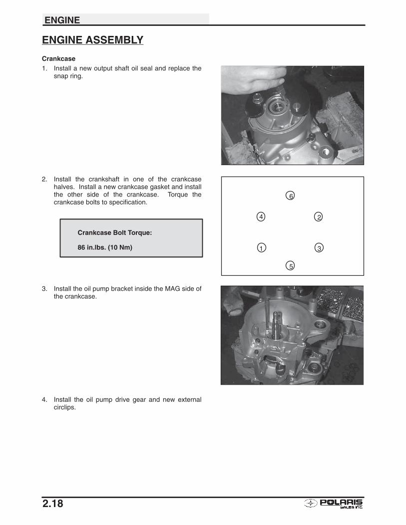
Crankcase1. Install a new output shaft oil seal and replace the
snap ring.
2. Install the crankshaft in one of the crankcasehalves. Install a new crankcase gasket and installthe other side of the crankcase. Torque thecrankcase bolts to specification.
3. Install the oil pump bracket inside the MAG side ofthe crankcase.
4. Install the oil pump drive gear and new externalcirclips.
1
2
3
4
5
6
Crankcase Bolt Torque:
86 in.lbs. (10 Nm)
ENGINE
2.19
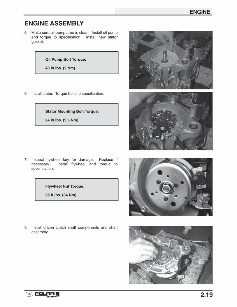
ENGINE ASSEMBLY5. Make sure oil pump area is clean. Install oil pump
and torque to specification. Install new statorgasket.
6. Install stator. Torque bolts to specification.
7. Inspect flywheel key for damage. Replace ifnecessary. Install flywheel and torque tospecification.
8. Install driven clutch shaft components and shaftassembly.
Oil Pump Bolt Torque:
43 in.lbs. (5 Nm)
Stator Mounting Bolt Torque:
84 in.lbs. (9.5 Nm)
Flywheel Nut Torque:
25 ft.lbs. (34 Nm)
ENGINE
2.20
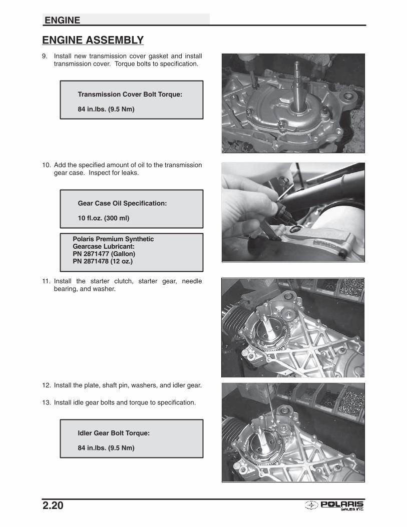
ENGINE ASSEMBLY9. Install new transmission cover gasket and install
transmission cover. Torque bolts to specification.
10. Add the specified amount of oil to the transmissiongear case. Inspect for leaks.
11. Install the starter clutch, starter gear, needlebearing, and washer.
12. Install the plate, shaft pin, washers, and idler gear.
13. Install idle gear bolts and torque to specification.
Transmission Cover Bolt Torque:
84 in.lbs. (9.5 Nm)
Gear Case Oil Specification:
10 fl.oz. (300 ml)
Polaris Premium SyntheticGearcase Lubricant:PN 2871477 (Gallon)PN 2871478 (12 oz.)
Idler Gear Bolt Torque:
84 in.lbs. (9.5 Nm)
ENGINE
2.21
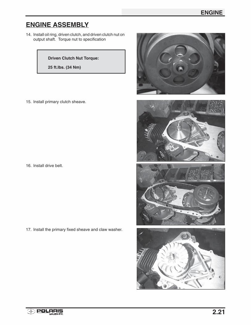
ENGINE ASSEMBLY14. Install oil ring, driven clutch, and driven clutch nut on
output shaft. Torque nut to specification
15. Install primary clutch sheave.
16. Install drive belt.
17. Install the primary fixed sheave and claw washer.
Driven Clutch Nut Torque:
25 ft.lbs. (34 Nm)
ENGINE
2.22
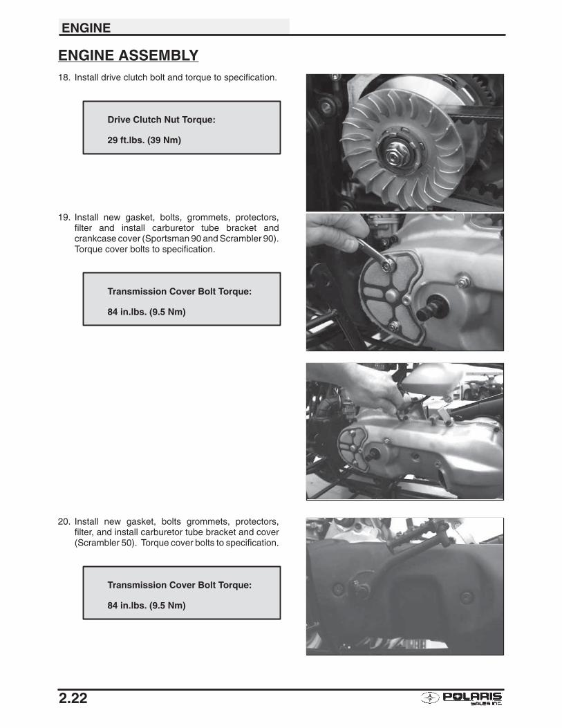
ENGINE ASSEMBLY18. Install drive clutch bolt and torque to specification.
19. Install new gasket, bolts, grommets, protectors,filter and install carburetor tube bracket andcrankcase cover (Sportsman 90 and Scrambler 90).Torque cover bolts to specification.
20. Install new gasket, bolts grommets, protectors,filter, and install carburetor tube bracket and cover(Scrambler 50). Torque cover bolts to specification.
Drive Clutch Nut Torque:
29 ft.lbs. (39 Nm)
Transmission Cover Bolt Torque:
84 in.lbs. (9.5 Nm)
Transmission Cover Bolt Torque:
84 in.lbs. (9.5 Nm)
ENGINE
2.23
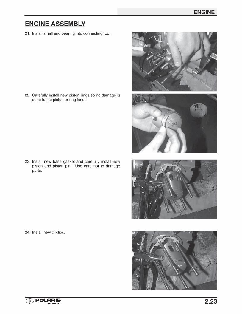
ENGINE ASSEMBLY21. Install small end bearing into connecting rod.
22. Carefully install new piston rings so no damage isdone to the piston or ring lands.
23. Install new base gasket and carefully install newpiston and piston pin. Use care not to damageparts.
24. Install new circlips.
ENGINE
2.24
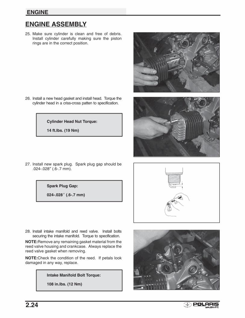
ENGINE ASSEMBLY25. Make sure cylinder is clean and free of debris.
Install cylinder carefully making sure the pistonrings are in the correct position.
26. Install a new head gasket and install head. Torque thecylinder head in a criss-cross patten to specification.
27. Install new spark plug. Spark plug gap should be.024-.028″ (.6-.7 mm).
28. Install intake manifold and reed valve. Install boltssecuring the intake manifold. Torque to specification.
NOTE:Remove any remaining gasket material from thereed valve housing and crankcase. Always replace thereed valve gasket when removing.
NOTE:Check the condition of the reed. If petals lookdamaged in any way, replace.
Cylinder Head Nut Torque:
14 ft.lbs. (19 Nm)
Spark Plug Gap:
024-.028� (.6-.7 mm)
Intake Manifold Bolt Torque:
108 in.lbs. (12 Nm)
ENGINE
2.25
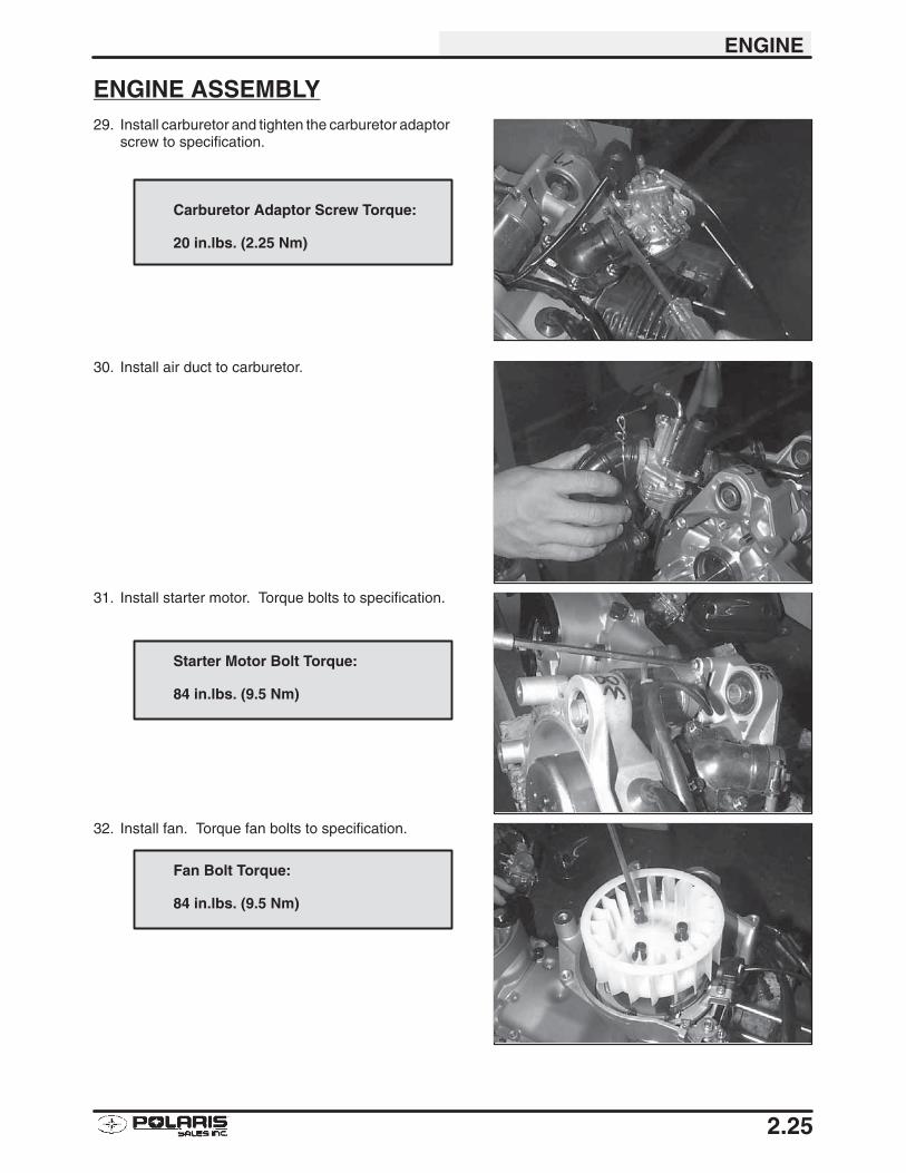
ENGINE ASSEMBLY29. Install carburetor and tighten the carburetor adaptor
screw to specification.
30. Install air duct to carburetor.
31. Install starter motor. Torque bolts to specification.
32. Install fan. Torque fan bolts to specification.
Carburetor Adaptor Screw Torque:
20 in.lbs. (2.25 Nm)
Starter Motor Bolt Torque:
84 in.lbs. (9.5 Nm)
Fan Bolt Torque:
84 in.lbs. (9.5 Nm)
ENGINE
2.26
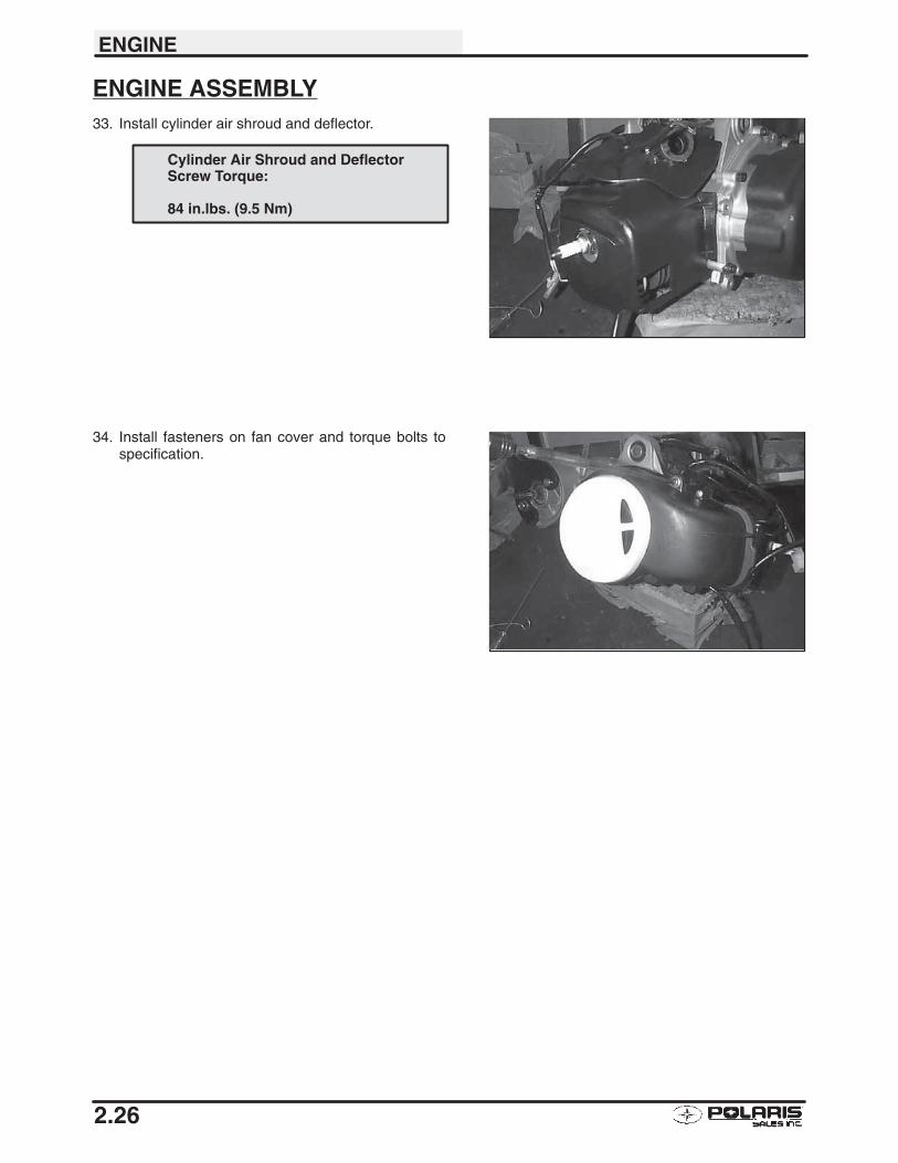
ENGINE ASSEMBLY33. Install cylinder air shroud and deflector.
34. Install fasteners on fan cover and torque bolts tospecification.
Cylinder Air Shroud and DeflectorScrew Torque:
84 in.lbs. (9.5 Nm)
ENGINE
2.27
SPARK PLUG FOULING� Spark plug cap loose or faulty
� Choke cable adjustment or plunger/cable sticking
� Foreign material on choke plunger seat or plunger
� Incorrect spark plug heat range or gap
� Carburetor inlet needle and seat worn or leaking
� Jet needle and/or needle jet worn or improperly adjusted
� Excessive carburetor vibration (loose or missing needle jet locating pins)
� Loose jets in carburetor or calibration incorrect for altitude/temperature
� Incorrect float level setting� PVT system calibrated incorrectly or components worn or mis-adjusted
� Fuel quality poor (old) or octane too high
� Low compression
� Restricted exhaust
� Weak ignition (loose coil ground, faulty coil, stator, or ETC switch)
� ETC switch mis-adjusted
� Restricted air filter (main or pre-cleaner) or breather system
� Improperly assembled air intake system
� Restricted engine breather system
� Oil contaminated with fuel� Restricted oil tank vent
ENGINE
2.28
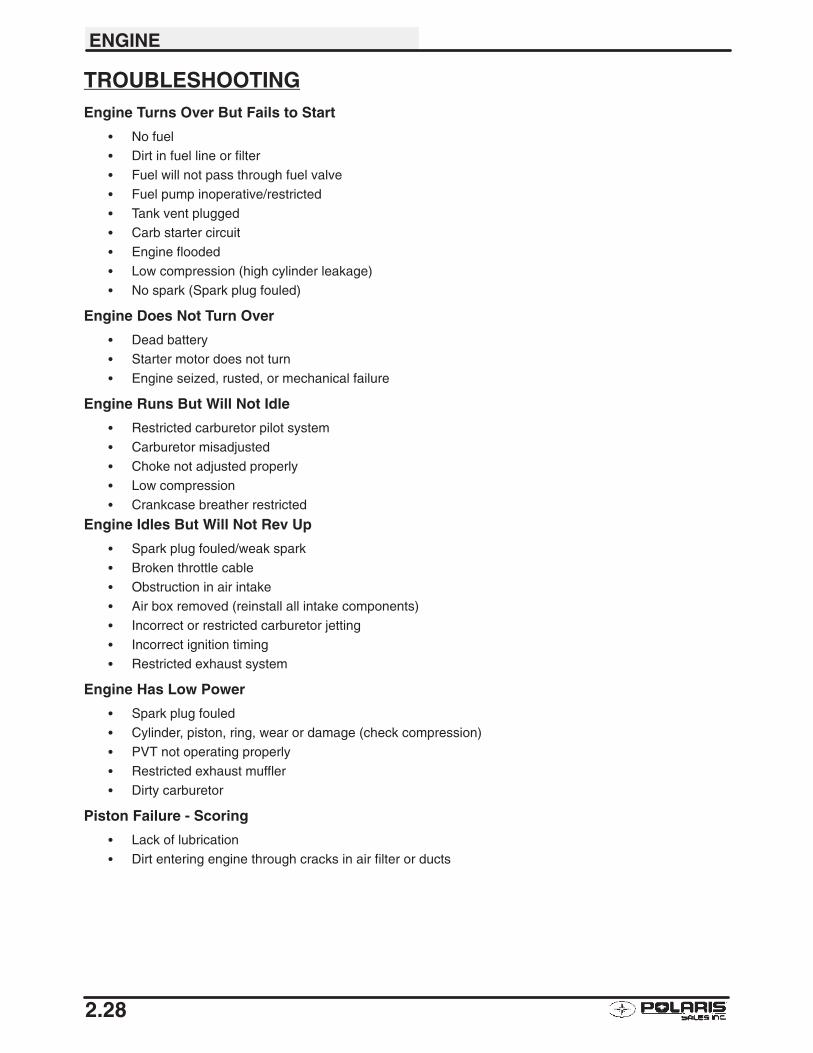
TROUBLESHOOTINGEngine Turns Over But Fails to Start
� No fuel� Dirt in fuel line or filter
� Fuel will not pass through fuel valve
� Fuel pump inoperative/restricted
� Tank vent plugged
� Carb starter circuit
� Engine flooded
� Low compression (high cylinder leakage)
� No spark (Spark plug fouled)
Engine Does Not Turn Over
� Dead battery
� Starter motor does not turn
� Engine seized, rusted, or mechanical failure
Engine Runs But Will Not Idle
� Restricted carburetor pilot system
� Carburetor misadjusted
� Choke not adjusted properly
� Low compression
� Crankcase breather restricted
Engine Idles But Will Not Rev Up
� Spark plug fouled/weak spark
� Broken throttle cable
� Obstruction in air intake� Air box removed (reinstall all intake components)
� Incorrect or restricted carburetor jetting
� Incorrect ignition timing
� Restricted exhaust system
Engine Has Low Power
� Spark plug fouled
� Cylinder, piston, ring, wear or damage (check compression)
� PVT not operating properly
� Restricted exhaust muffler
� Dirty carburetor
Piston Failure - Scoring
� Lack of lubrication
� Dirt entering engine through cracks in air filter or ducts
ENGINE
2.29
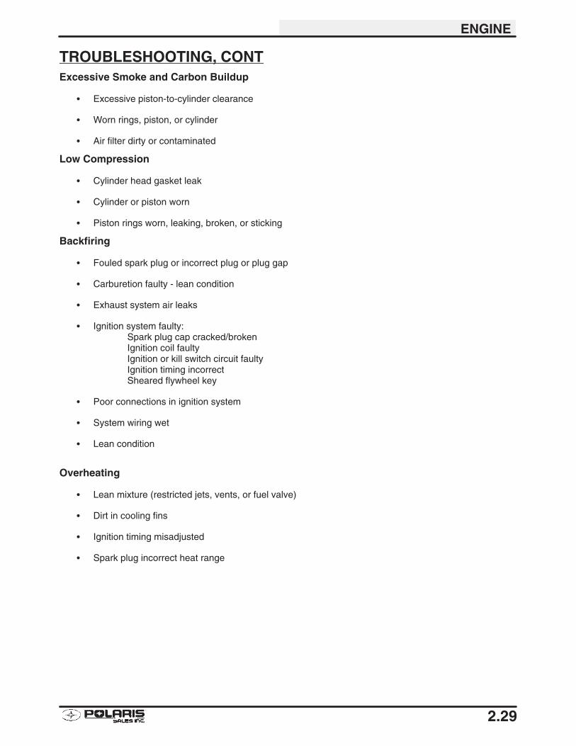
TROUBLESHOOTING, CONTExcessive Smoke and Carbon Buildup
� Excessive piston-to-cylinder clearance
� Worn rings, piston, or cylinder
� Air filter dirty or contaminated
Low Compression
� Cylinder head gasket leak
� Cylinder or piston worn
� Piston rings worn, leaking, broken, or sticking
Backfiring
� Fouled spark plug or incorrect plug or plug gap
� Carburetion faulty - lean condition
� Exhaust system air leaks
� Ignition system faulty:Spark plug cap cracked/brokenIgnition coil faultyIgnition or kill switch circuit faultyIgnition timing incorrectSheared flywheel key
� Poor connections in ignition system
� System wiring wet
� Lean condition
Overheating
� Lean mixture (restricted jets, vents, or fuel valve)
� Dirt in cooling fins
� Ignition timing misadjusted
� Spark plug incorrect heat range

3
CHAPTER 3FUEL SYSTEM/CARBURETION
Fuel System Warnings 3.1. . . . . . . . . . . . . . . . . . . . . . . .
Carburetor Operation 3.2. . . . . . . . . . . . . . . . . . . . . . . . .
Float System 3.2. . . . . . . . . . . . . . . . . . . . . . . . . . . . . . . . .
Pilot Jet / Pilot Air Screw / Air/Fuel Mixture 3.3. . . . . . .
Jet Needle / Needle Jet / Throttle Opening 3.4. . . . . . .
Throttle Valve / Main Jet 3.5. . . . . . . . . . . . . . . . . . . . . . .
Pilot System 3.6. . . . . . . . . . . . . . . . . . . . . . . . . . . . . . . . .
Slide Cutaway / 1/8-3/8 Throttle 3.7. . . . . . . . . . . . . . . .
Jet Needle / Needle Jet / 3/8-3/4 Throttle 3.8. . . . . . . .
Main System / 3/4 to Full Throttle 3.9. . . . . . . . . . . . . . .
Fuel Delivery 3.10. . . . . . . . . . . . . . . . . . . . . . . . . . . . . . . . .
Vent Systems / Float Height 3.11. . . . . . . . . . . . . . . . . . . .
Needle and Seat Leakage Test 3.11. . . . . . . . . . . . . . . . .
Carburetor Float Bowl Draining 3.12. . . . . . . . . . . . . . . . .
Carburetor Exploded View 3.13. . . . . . . . . . . . . . . . . . . . .
Troubleshooting 3.14-3.15. . . . . . . . . . . . . . . . . . . . . . . . . . . . . .

FUEL SYSTEM/CARBURETION
3.1
FUEL SYSTEM
WARNING
Gasoline is extremely flammable and explosive under certain conditions.
Always stop the engine and refuel outdoors or in a well ventilated area.
Do not smoke or allow open flames or sparks in or near the area where refueling is performed or wheregasoline is stored.
Do not overfill the tank. Do not fill the tank neck.
If you get gasoline in your eyes or if you swallow gasoline, see your doctor immediately.
If you spill gasoline on your skin or clothing, immediately wash it off with soap and water and change clothing.
Never start the engine or let it run in an enclosed area. Gasoline powered engine exhaust fumes are poison-ous and can cause loss of consciousness and death in a short time.
Never drain the float bowl when the engine is hot. Severe burns may result.
FUEL SYSTEM/CARBURETION
3.2
CARBURETOR OPERATION
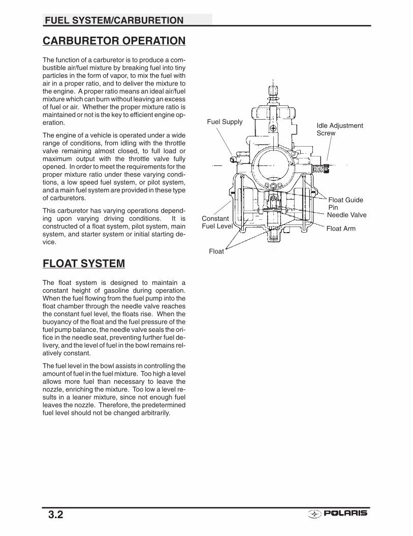
The function of a carburetor is to produce a com-bustible air/fuel mixture by breaking fuel into tinyparticles in the form of vapor, to mix the fuel withair in a proper ratio, and to deliver the mixture tothe engine. A proper ratio means an ideal air/fuelmixture which can burn without leaving an excessof fuel or air. Whether the proper mixture ratio ismaintained or not is the key to efficient engine op-eration.
The engine of a vehicle is operated under a widerange of conditions, from idling with the throttlevalve remaining almost closed, to full load ormaximum output with the throttle valve fullyopened. In order to meet the requirements for theproper mixture ratio under these varying condi-tions, a low speed fuel system, or pilot system,and a main fuel system are provided in these typeof carburetors.
This carburetor has varying operations depend-ing upon varying driving conditions. It isconstructed of a float system, pilot system, mainsystem, and starter system or initial starting de-vice.
FLOAT SYSTEM
The float system is designed to maintain aconstant height of gasoline during operation.When the fuel flowing from the fuel pump into thefloat chamber through the needle valve reachesthe constant fuel level, the floats rise. When thebuoyancy of the float and the fuel pressure of thefuel pump balance, the needle valve seals the ori-fice in the needle seat, preventing further fuel de-livery, and the level of fuel in the bowl remains rel-atively constant.
The fuel level in the bowl assists in controlling theamount of fuel in the fuel mixture. Too high a levelallows more fuel than necessary to leave thenozzle, enriching the mixture. Too low a level re-sults in a leaner mixture, since not enough fuelleaves the nozzle. Therefore, the predeterminedfuel level should not be changed arbitrarily.
Float GuidePinNeedle Valve
Float Arm
Float
Fuel Supply
ConstantFuel Level
Idle AdjustmentScrew
FUEL SYSTEM/CARBURETION
3.3
PILOT JET
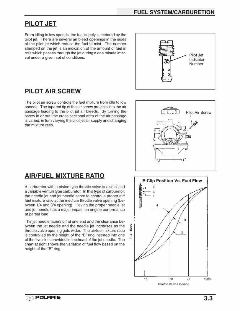
From idling to low speeds, the fuel supply is metered by thepilot jet. There are several air bleed openings in the sidesof the pilot jet which reduce the fuel to mist. The numberstamped on the jet is an indication of the amount of fuel incc’s which passes through the jet during a one minute inter-val under a given set of conditions.
PILOT AIR SCREW
The pilot air screw controls the fuel mixture from idle to lowspeeds. The tapered tip of the air screw projects into the airpassage leading to the pilot jet air bleeds. By turning thescrew in or out, the cross sectional area of the air passageis varied, in turn varying the pilot jet air supply and changingthe mixture ratio.
AIR/FUEL MIXTURE RATIO
A carburetor with a piston type throttle valve is also calleda variable venturi type carburetor. In this type of carburetor,the needle jet and jet needle serve to control a proper air/fuel mixture ratio at the medium throttle valve opening (be-tween 1/4 and 3/4 opening). Having the proper needle jetand jet needle has a major impact on engine performanceat partial load.
The jet needle tapers off at one end and the clearance be-tween the jet needle and the needle jet increases as thethrottle valve opening gets wider. The air/fuel mixture ratiois controlled by the height of the “E” ring inserted into oneof the five slots provided in the head of the jet needle. Thechart at right shows the variation of fuel flow based on theheight of the “E” ring.
Pilot JetIndicatorNumber
Pilot Air Screw
2
34
4
3
2
15 50 75 100%
Throttle Valve Opening
E-Clip Position Vs. Fuel Flow
FUEL SYSTEM/CARBURETION
3.4
JET NEEDLE
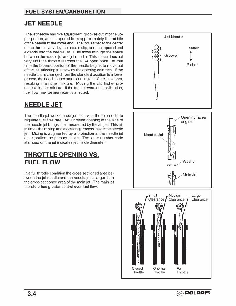
The jet needle has five adjustment grooves cut into the up-per portion, and is tapered from approximately the middleof the needle to the lower end. The top is fixed to the centerof the throttle valve by the needle clip, and the tapered endextends into the needle jet. Fuel flows through the spacebetween the needle jet and jet needle. This space does notvary until the throttle reaches the 1/4 open point. At thattime the tapered portion of the needle begins to move outof the jet, affecting fuel flow as the opening enlarges. If theneedle clip is changed from the standard position to a lowergroove, the needle taper starts coming out of the jet sooner,resulting in a richer mixture. Moving the clip higher pro-duces a leaner mixture. If the taper is worn due to vibration,fuel flow may be significantly affected.
NEEDLE JET
The needle jet works in conjunction with the jet needle toregulate fuel flow rate. An air bleed opening in the side ofthe needle jet brings in air measured by the air jet. This airinitiates the mixing and atomizing process inside the needlejet. Mixing is augmented by a projection at the needle jetoutlet, called the primary choke. The letter number codestamped on the jet indicates jet inside diameter.
THROTTLE OPENING VS.FUEL FLOW
In a full throttle condition the cross sectioned area be-tween the jet needle and the needle jet is larger thanthe cross sectioned area of the main jet. The main jettherefore has greater control over fuel flow.
Needle Jet
Opening facesengine
Washer
Main Jet
SmallClearance
MediumClearance
LargeClearance
ClosedThrottle
One-halfThrottle
FullThrottle
Groove
Leaner
Richer
Jet Needle
FUEL SYSTEM/CARBURETION
3.5
THROTTLE VALVE
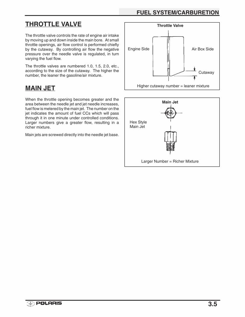
The throttle valve controls the rate of engine air intakeby moving up and down inside the main bore. At smallthrottle openings, air flow control is performed chieflyby the cutaway. By controlling air flow the negativepressure over the needle valve is regulated, in turnvarying the fuel flow.
The throttle valves are numbered 1.0, 1.5, 2.0, etc.,according to the size of the cutaway. The higher thenumber, the leaner the gasoline/air mixture.
MAIN JET
When the throttle opening becomes greater and thearea between the needle jet and jet needle increases,fuel flow is metered by the main jet. The number on thejet indicates the amount of fuel CCs which will passthrough it in one minute under controlled conditions.Larger numbers give a greater flow, resulting in aricher mixture.
Main jets are screwed directly into the needle jet base.
Cutaway
Air Box SideEngine Side
Higher cutaway number = leaner mixture
Throttle Valve
Hex StyleMain Jet
Main Jet
Larger Number = Richer Mixture
FUEL SYSTEM/CARBURETION
3.6
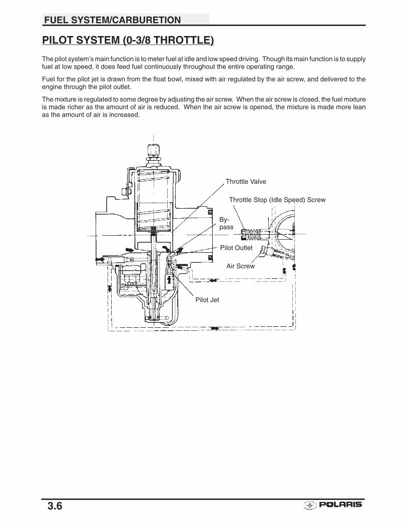
PILOT SYSTEM (0-3/8 THROTTLE)
The pilot system’s main function is to meter fuel at idle and low speed driving. Though its main function is to supplyfuel at low speed, it does feed fuel continuously throughout the entire operating range.
Fuel for the pilot jet is drawn from the float bowl, mixed with air regulated by the air screw, and delivered to theengine through the pilot outlet.
The mixture is regulated to some degree by adjusting the air screw. When the air screw is closed, the fuel mixtureis made richer as the amount of air is reduced. When the air screw is opened, the mixture is made more leanas the amount of air is increased.
Throttle Valve
Throttle Stop (Idle Speed) Screw
By-pass
Pilot Outlet
Air Screw
Pilot Jet
FUEL SYSTEM/CARBURETION
3.7
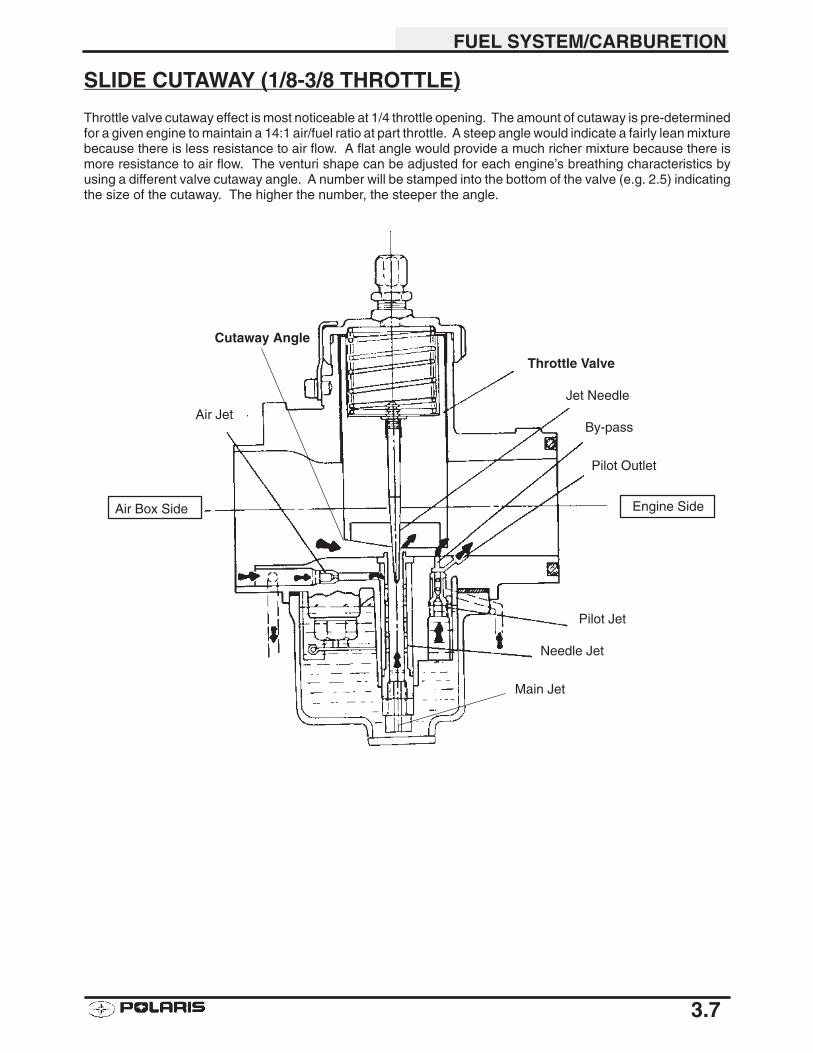
SLIDE CUTAWAY (1/8-3/8 THROTTLE)
Throttle valve cutaway effect is most noticeable at 1/4 throttle opening. The amount of cutaway is pre-determinedfor a given engine to maintain a 14:1 air/fuel ratio at part throttle. A steep angle would indicate a fairly lean mixturebecause there is less resistance to air flow. A flat angle would provide a much richer mixture because there ismore resistance to air flow. The venturi shape can be adjusted for each engine’s breathing characteristics byusing a different valve cutaway angle. A number will be stamped into the bottom of the valve (e.g. 2.5) indicatingthe size of the cutaway. The higher the number, the steeper the angle.
Air Jet
Throttle Valve
Jet Needle
By-pass
Pilot Outlet
Pilot Jet
Needle Jet
Main Jet
Cutaway Angle
Air Box Side Engine Side
FUEL SYSTEM/CARBURETION
3.8
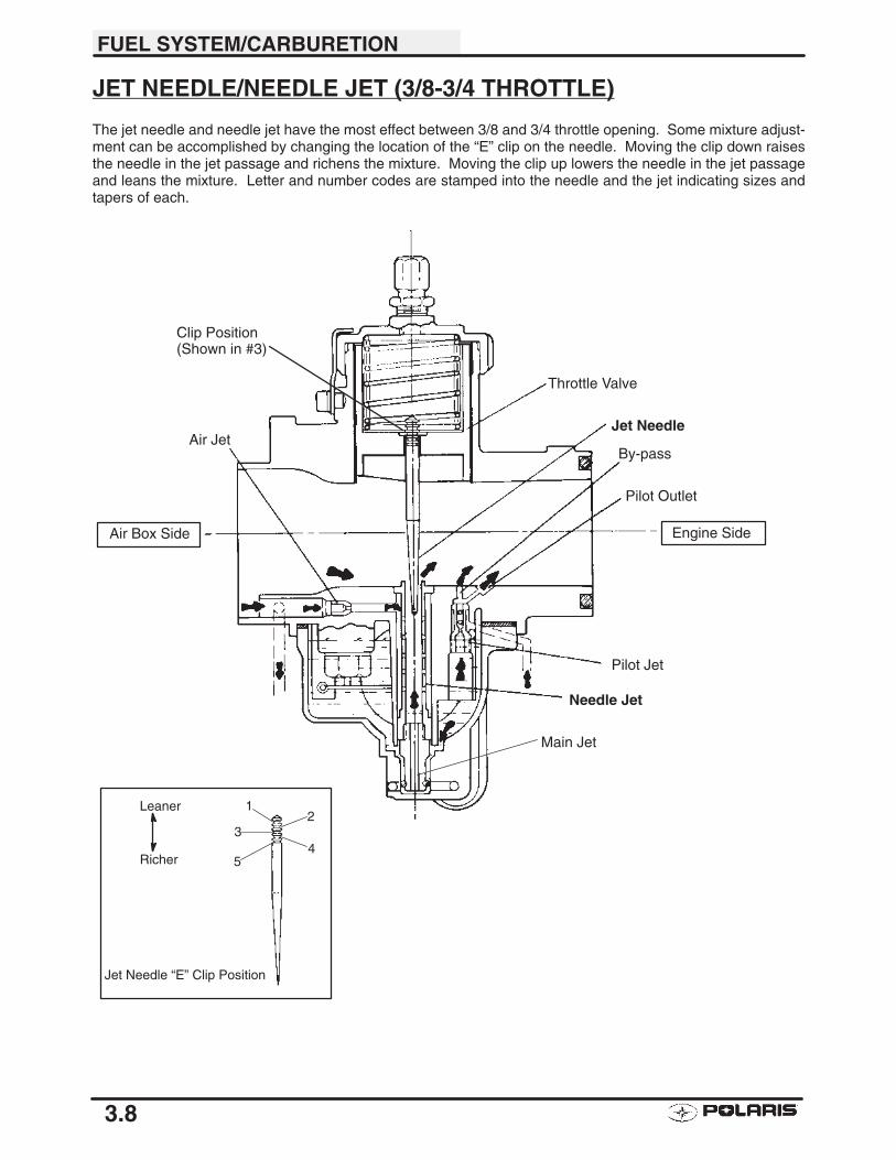
JET NEEDLE/NEEDLE JET (3/8-3/4 THROTTLE)
The jet needle and needle jet have the most effect between 3/8 and 3/4 throttle opening. Some mixture adjust-ment can be accomplished by changing the location of the “E” clip on the needle. Moving the clip down raisesthe needle in the jet passage and richens the mixture. Moving the clip up lowers the needle in the jet passageand leans the mixture. Letter and number codes are stamped into the needle and the jet indicating sizes andtapers of each.
Air Jet
Throttle Valve
Jet Needle
By-pass
Pilot Outlet
Pilot Jet
Needle Jet
Main Jet
Clip Position(Shown in #3)
12
34
5
Jet Needle “E” Clip Position
Leaner
Richer
Air Box Side Engine Side
FUEL SYSTEM/CARBURETION
3.9
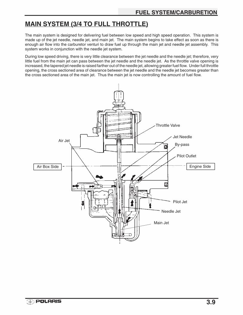
MAIN SYSTEM (3/4 TO FULL THROTTLE)
The main system is designed for delivering fuel between low speed and high speed operation. This system ismade up of the jet needle, needle jet, and main jet. The main system begins to take effect as soon as there isenough air flow into the carburetor venturi to draw fuel up through the main jet and needle jet assembly. Thissystem works in conjunction with the needle jet system.
During low speed driving, there is very little clearance between the jet needle and the needle jet; therefore, verylittle fuel from the main jet can pass between the jet needle and the needle jet. As the throttle valve opening isincreased, the tapered jet needle is raised farther out of the needle jet, allowing greater fuel flow. Under full throttleopening, the cross sectioned area of clearance between the jet needle and the needle jet becomes greater thanthe cross sectioned area of the main jet. Thus the main jet is now controlling the amount of fuel flow.
Air Jet
Throttle Valve
Jet Needle
By-pass
Pilot Outlet
Pilot Jet
Needle Jet
Main Jet
Air Box Side Engine Side
FUEL SYSTEM/CARBURETION
3.10
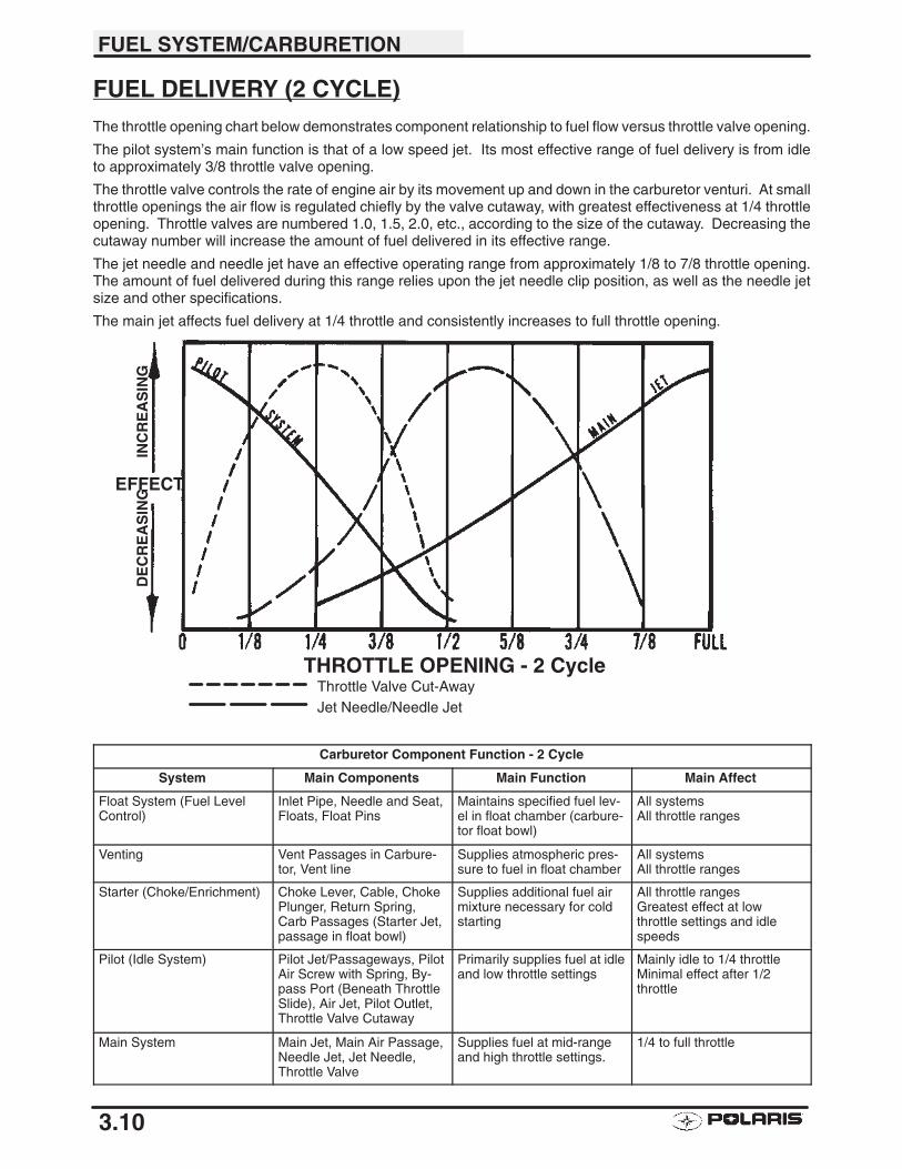
FUEL DELIVERY (2 CYCLE)The throttle opening chart below demonstrates component relationship to fuel flow versus throttle valve opening.
The pilot system’s main function is that of a low speed jet. Its most effective range of fuel delivery is from idleto approximately 3/8 throttle valve opening.
The throttle valve controls the rate of engine air by its movement up and down in the carburetor venturi. At smallthrottle openings the air flow is regulated chiefly by the valve cutaway, with greatest effectiveness at 1/4 throttleopening. Throttle valves are numbered 1.0, 1.5, 2.0, etc., according to the size of the cutaway. Decreasing thecutaway number will increase the amount of fuel delivered in its effective range.
The jet needle and needle jet have an effective operating range from approximately 1/8 to 7/8 throttle opening.The amount of fuel delivered during this range relies upon the jet needle clip position, as well as the needle jetsize and other specifications.
The main jet affects fuel delivery at 1/4 throttle and consistently increases to full throttle opening.
Carburetor Component Function - 2 Cycle
System Main Components Main Function Main Affect
Float System (Fuel LevelControl)
Inlet Pipe, Needle and Seat,Floats, Float Pins
Maintains specified fuel lev-el in float chamber (carbure-tor float bowl)
All systemsAll throttle ranges
Venting Vent Passages in Carbure-tor, Vent line
Supplies atmospheric pres-sure to fuel in float chamber
All systemsAll throttle ranges
Starter (Choke/Enrichment) Choke Lever, Cable, ChokePlunger, Return Spring,Carb Passages (Starter Jet,passage in float bowl)
Supplies additional fuel airmixture necessary for coldstarting
All throttle rangesGreatest effect at lowthrottle settings and idlespeeds
Pilot (Idle System) Pilot Jet/Passageways, PilotAir Screw with Spring, By-pass Port (Beneath ThrottleSlide), Air Jet, Pilot Outlet,Throttle Valve Cutaway
Primarily supplies fuel at idleand low throttle settings
Mainly idle to 1/4 throttleMinimal effect after 1/2throttle
Main System Main Jet, Main Air Passage,Needle Jet, Jet Needle,Throttle Valve
Supplies fuel at mid-rangeand high throttle settings.
1/4 to full throttle
INC
RE
AS
ING
DE
CR
EA
SIN
G
EFFECT
THROTTLE OPENING - 2 CycleThrottle Valve Cut-AwayJet Needle/Needle Jet
FUEL SYSTEM/CARBURETION
3.11
VENT SYSTEMSThe fuel tank and carburetor float bowl vent lines supply atmospheric pressure to the fuel in the tank and floatbowl. The lines must be free of kinks and restrictions to prevent lean mixture and possible engine damage. Ventlines must be properly routed to prevent damage to the line and to prevent contaminants from entering the carbu-retor or fuel tank.
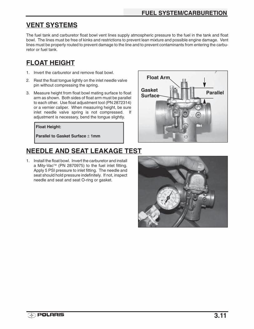
FLOAT HEIGHT1. Invert the carburetor and remove float bowl.
2. Rest the float tongue lightly on the inlet needle valvepin without compressing the spring.
3. Measure height from float bowl mating surface to floatarm as shown. Both sides of float arm must be parallelto each other. Use float adjustment tool (PN 2872314)or a vernier caliper. When measuring height, be sureinlet needle valve spring is not compressed. Ifadjustment is necessary, bend the tongue slightly.
NEEDLE AND SEAT LEAKAGE TEST1. Install the float bowl. Invert the carburetor and install
a Mity-Vac™ (PN 2870975) to the fuel inlet fitting.Apply 5 PSI pressure to inlet fitting. The needle andseat should hold pressure indefinitely. If not, inspectneedle and seat and seat O-ring or gasket.
Parallel
Float Arm
GasketSurface
Float Height:
Parallel to Gasket Surface ± 1mm

FUEL SYSTEM/CARBURETION
3.12
CARBURETOR FLOAT BOWL DRAINING
The carburetor float bowl should be drained periodically toremove moisture or sediment from the bowl, or before ex-tended periods of storage.
NOTE: A drain plug is located on the side of the float bowl.
1. Turn fuel valve to the off position.
2. Place a clean container beneath the bowl drain spigotor bowl drain hose.
3. Loosen drain plug and allow fuel in the float bowl andfuel line to drain completely.
4. Inspect the drained fuel for water or sediment.
5. TIghten drain plug.
6. Turn fuel valve to “on”.
7. Inspect carburetor for fuel leaks.
8. Start machine and re-check for leaks.
OFF
RES
ON
FUEL SYSTEM/CARBURETION
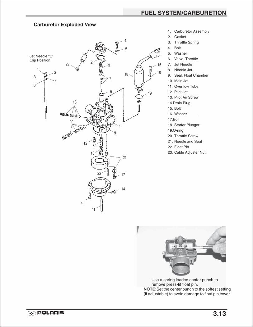
3.13
1. Carburetor Assembly
2. Gasket
3. Throttle Spring
4. Bolt
5. Washer
6. Valve, Throttle
7. Jet Needle
8. Needle Jet
9. Seal, Float Chamber
10. Main Jet
11. Overflow Tube
12. Pilot Jet
13. Pilot Air Screw
14.Drain Plug
15. Bolt
16. Washer .
17.Bolt
18. Starter Plunger
19.O-ring
20. Throttle Screw
21. Needle and Seat
22. Float Pin
23. Cable Adjuster Nut
Carburetor Exploded View
12
34
5
Jet Needle “E” Clip Position
Use a spring loaded center punch toremove press-fit float pin.
NOTE:Set the center punch to the softest setting(if adjustable) to avoid damage to float pin tower.
23 2
4
5
3
718
15
16
196
13
201
9
128
1021
1722
14
11
4
FUEL SYSTEM/CARBURETION
3.14
TROUBLESHOOTING
FUEL STARVATION/LEAN MIXTURE
Symptoms: Hard start or no start, bog, backfire, popping through intake / exhaust, hesitation, detonation, lowpower, spark plug erosion, engine runs hot, surging, high idle, idle speed erratic.
� No fuel in tank
� Restricted tank vent, or routed improperly� Fuel lines or fuel valve restricted
� Fuel filter plugged
� Carburetor vent line(s) restricted
� Plugged or restricted inlet needle and seat screen or inlet passage
� Clogged jets or passages
� Float stuck, holding inlet needle closed or inlet needle stuck
� Float level too low
� Intake air leak (throttle shaft, intake ducts, airbox or air cleaner cover)
� Jet needle position incorrect
� Incorrect pilot screw adjustment
RICH MIXTURE
Symptoms: Fouls spark plugs, black, sooty exhaust smoke, rough idle, poor fuel economy, engine runs rough/misses, poor performance, bog, engine loads up, backfire.
� Air intake restricted (inspect intake duct)
� Air filter dirty/plugged
� Choke plunger sticking, incorrectly adjusted choke� Choke cable binding or improperly routed
� Incorrect pilot air/fuel screw adjustment
� Faulty inlet needle and seat
� Faulty inlet needle seat O-Ring
� Float level too high
� Poor fuel quality (old fuel)
� Loose jets
� Worn jet needle/needle jet or other carburetor parts
� Dirty carburetor (air bleed passages or jets)
� Fouled spark plug
POOR IDLE
Symptoms: Idle too high.
� Idle adjusted improperly/idle mixture screw damaged
� Sticky throttle valve
� Throttle cable sticking, improperly adjusted, routed incorrectly� Choke cable sticking, improperly adjusted, routed incorrectly
FUEL SYSTEM/CARBURETION
3.15
TROUBLESHOOTING
IDLE TOO LOW� Choke cable incorrectly adjusted
� Idle speed set incorrectly� Idle mixture screw misadjusted or damaged
� Belt dragging
� Ignition timing incorrect
� Worn jet needle/needle jet
ERRATIC IDLE� Choke cable bending or incorrectly adjusted
� Throttle cable incorrectly adjusted
� Air leaks, dirty carburetor passages (pilot circuit)
� Pilot mixture screw damaged or adjusted incorrectly
� Tight valves
� Ignition timing incorrect
� Belt dragging
� Dirty air cleaner
� Engine worn� Spark plug fouled
� Idle speed set incorrectly (speed limiter)
� Worn jet needle/needle jet

4
CHAPTER 4BODY AND STEERING
Torque Specifications and Special Tools 4.1. . . . . . . . . . . .
Frame Photos 4.2. . . . . . . . . . . . . . . . . . . . . . . . . . . . . . . . . . .
Engine Mounting 4.3-4.4. . . . . . . . . . . . . . . . . . . . . . . . . . . . . . . .
Shocks and Springs 4.5. . . . . . . . . . . . . . . . . . . . . . . . . . . . . .
Suspension A-arms 4.6. . . . . . . . . . . . . . . . . . . . . . . . . . . . . .
Steering 4.7-4.8. . . . . . . . . . . . . . . . . . . . . . . . . . . . . . . . . . . . . . . .
Front Brake 4.9-4.10. . . . . . . . . . . . . . . . . . . . . . . . . . . . . . . . . . . . .
Rear Brake and Axle 4.10-4.13. . . . . . . . . . . . . . . . . . . . . . . . . . . . .
Fuel and Oil Tank 4.14. . . . . . . . . . . . . . . . . . . . . . . . . . . . . . . .
Front and Rear Cab 4.15. . . . . . . . . . . . . . . . . . . . . . . . . . . . . .
Handlebar 4.16-4.18. . . . . . . . . . . . . . . . . . . . . . . . . . . . . . . . . . . . . .
Muffler 4.18. . . . . . . . . . . . . . . . . . . . . . . . . . . . . . . . . . . . . . . . .

BODY / STEERING / SUSPENSION
4.1
TORQUE SPECIFICATIONSFront A-Arm Attaching Bolt 26-30 ft. lbs. (36-40 Nm). . . . . . . . . . . . . . . . . .
Handlebar Adjuster Block 84 in. lbs. (10 Nm). . . . . . . . . . . . . . . . . . .
Rear Shock Bolts 25 ft. lbs. (35 Nm). . . . . . . . . . . . . . . . . . . . . . . . . . .
Rear Wheel Hub Nut 78-81 ft. lbs. (108-112 Nm). . . . . . . . . . . . . . . . . . . . . . .
Front Shock Bolts 15 ft. lbs. (20 Nm). . . . . . . . . . . . . . . . . . . . . . . . . .
Swing Arm Mounting Bolt 26-30 ft. lbs. (36-40 Nm). . . . . . . . . . . . . . . . . . . .
Inner Tie Rod Bolts 33-40 ft. lbs. (45-55 Nm). . . . . . . . . . . . . . . . . . . . . . . . .
Outer Tie Rod Bolts 33-40 ft. lbs. (45-55 Nm). . . . . . . . . . . . . . . . . . . . . . . .
Tie Rod Jam Nuts 12-14 ft. lbs (17-19 Nm). . . . . . . . . . . . . . . . . . . . . . . . . .
Motor Mount Bolts-M8 22-25 ft. lbs (30-35 Nm). . . . . . . . . . . . . . . . . . . . . .
Motor Mount Bolts-M10 33-40 ft. lbs (45-55 Nm). . . . . . . . . . . . . . . . . . . . .
Spindle Nuts 40-45 ft. lbs (58-62 Nm). . . . . . . . . . . . . . . . . . . . . . . . . . . . . . .
Steering Post Mount Nuts 103 in. lbs (11.6 Nm). . . . . . . . . . . . . . . . . . .
Steering Post Nut 62-65 ft. lbs (86-90 Nm). . . . . . . . . . . . . . . . . . . . . . . . . .
Steering Nuts 62-65 ft. lbs (86-90 Nm). . . . . . . . . . . . . . . . . . . . . . . . . . . . . .
Sprocket Bolts 18 ft. lbs (25 Nm). . . . . . . . . . . . . . . . . . . . . . . . . . . . .
Chain Tensioner Bolt 84 in. lbs (10 Nm). . . . . . . . . . . . . . . . . . . . . . . .
Bearing Carrier Mounting Bolts 43 ft. lbs (60 Nm). . . . . . . . . . . . . . .
Rear Cover Mounting Bolts 84 in. lbs (10 Nm). . . . . . . . . . . . . . . . . .
Fuel Tank Mounting Bolts 103 in. lbs (12 Nm). . . . . . . . . . . . . . . . . . . .
Oil Tank Mounting Bolts 103 In. lbs (12 Nm). . . . . . . . . . . . . . . . . . . . .
Front Bumper Mounting Bolts 103 in. lbs (12 Nm). . . . . . . . . . . . . . . .
Cab Mounting Bolts 103 in. lbs (12 Nm). . . . . . . . . . . . . . . . . . . . . . . . .
Muffler Mounting Bolts 25 ft. lbs (34 Nm). . . . . . . . . . . . . . . . . . . . . .
NOTE: Refer to exploded views throughout this chapter for identification and location of components.
SPECIAL TOOLSDescription Part No.
Shock Spanner Wrench 2870872. . . . . . . . . . . . . .
Shock Spring Compressor Tool 2870623. . . . . . .
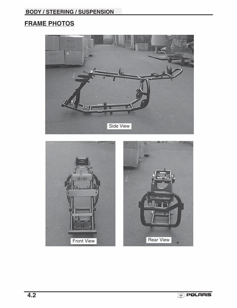
BODY / STEERING / SUSPENSION
4.2
FRAME PHOTOS
Side View
Front View Rear View
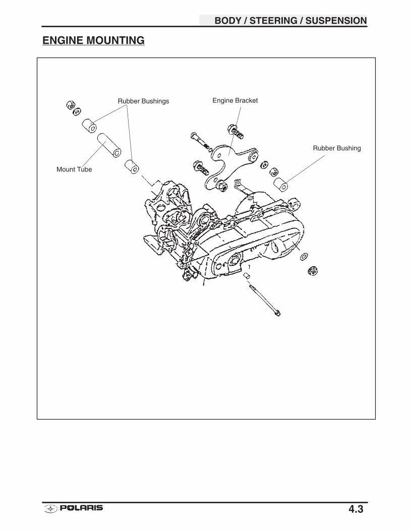
BODY / STEERING / SUSPENSION
4.3
ENGINE MOUNTING
Rubber Bushings
Mount Tube
Engine Bracket
Rubber Bushing
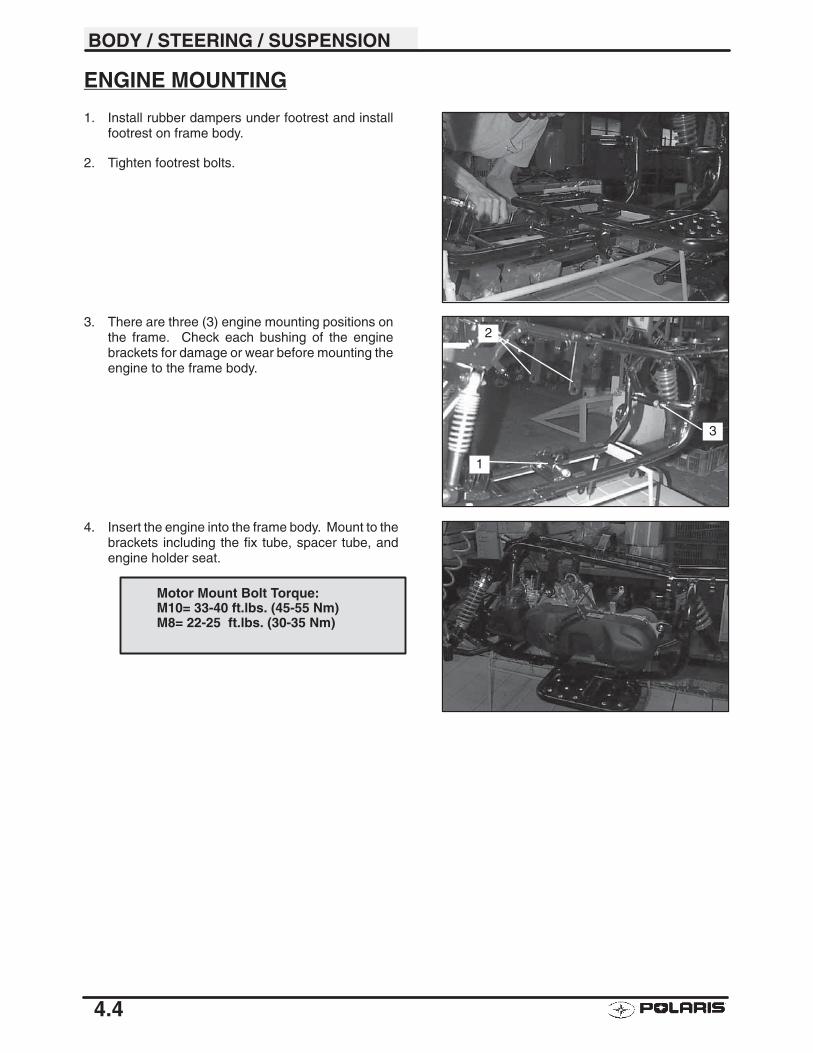
BODY / STEERING / SUSPENSION
4.4
ENGINE MOUNTING
1. Install rubber dampers under footrest and installfootrest on frame body.
2. Tighten footrest bolts.
3. There are three (3) engine mounting positions onthe frame. Check each bushing of the enginebrackets for damage or wear before mounting theengine to the frame body.
4. Insert the engine into the frame body. Mount to thebrackets including the fix tube, spacer tube, andengine holder seat.
1
2
3
Motor Mount Bolt Torque:M10= 33-40 ft.lbs. (45-55 Nm)M8= 22-25 ft.lbs. (30-35 Nm)
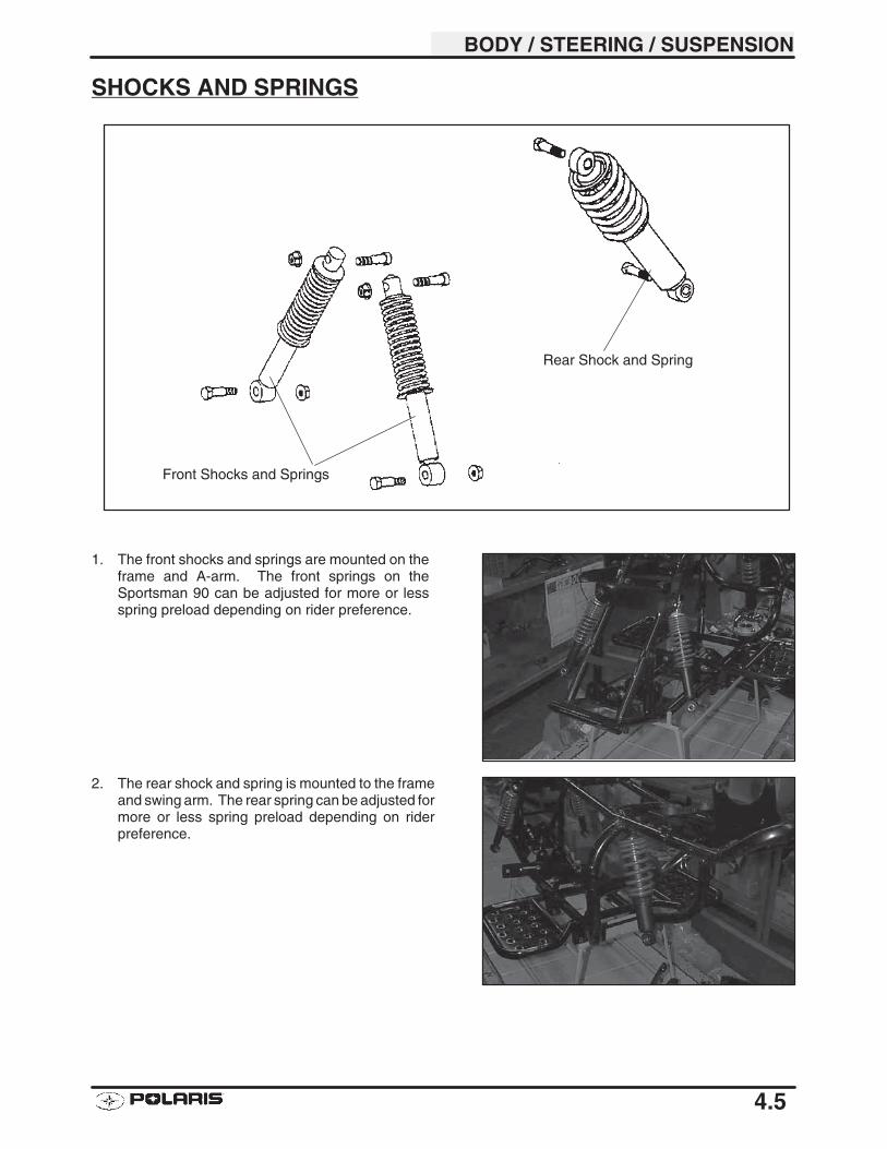
BODY / STEERING / SUSPENSION
4.5
SHOCKS AND SPRINGS
1. The front shocks and springs are mounted on theframe and A-arm. The front springs on theSportsman 90 can be adjusted for more or lessspring preload depending on rider preference.
2. The rear shock and spring is mounted to the frameand swing arm. The rear spring can be adjusted formore or less spring preload depending on riderpreference.
Front Shocks and Springs
Rear Shock and Spring
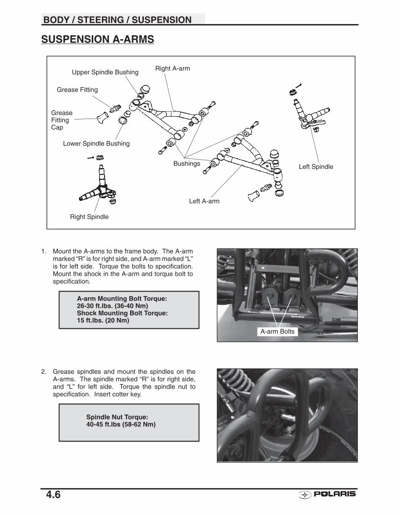
BODY / STEERING / SUSPENSION
4.6
SUSPENSION A-ARMS
1. Mount the A-arms to the frame body. The A-armmarked “R” is for right side, and A-arm marked “L”is for left side. Torque the bolts to specification.Mount the shock in the A-arm and torque bolt tospecification.
2. Grease spindles and mount the spindles on theA-arms. The spindle marked “R” is for right side,and “L” for left side. Torque the spindle nut tospecification. Insert cotter key.
A-arm Bolts
A-arm Mounting Bolt Torque:26-30 ft.lbs. (36-40 Nm)Shock Mounting Bolt Torque:15 ft.lbs. (20 Nm)
Spindle Nut Torque:40-45 ft.lbs (58-62 Nm)
Right A-arm
Bushings
Upper Spindle Bushing
Lower Spindle Bushing
Left A-arm
Right Spindle
Left Spindle
Grease Fitting
GreaseFittingCap
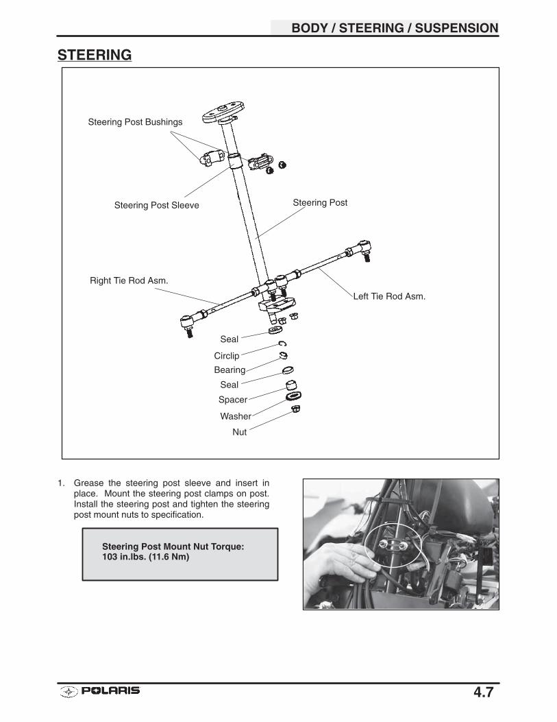
BODY / STEERING / SUSPENSION
4.7
STEERING
1. Grease the steering post sleeve and insert inplace. Mount the steering post clamps on post.Install the steering post and tighten the steeringpost mount nuts to specification.
Steering Post Mount Nut Torque:103 in.lbs. (11.6 Nm)
Steering Post
Steering Post Bushings
Left Tie Rod Asm.
Right Tie Rod Asm.
Steering Post Sleeve
Seal
Circlip
Bearing
Seal
Spacer
Washer
Nut
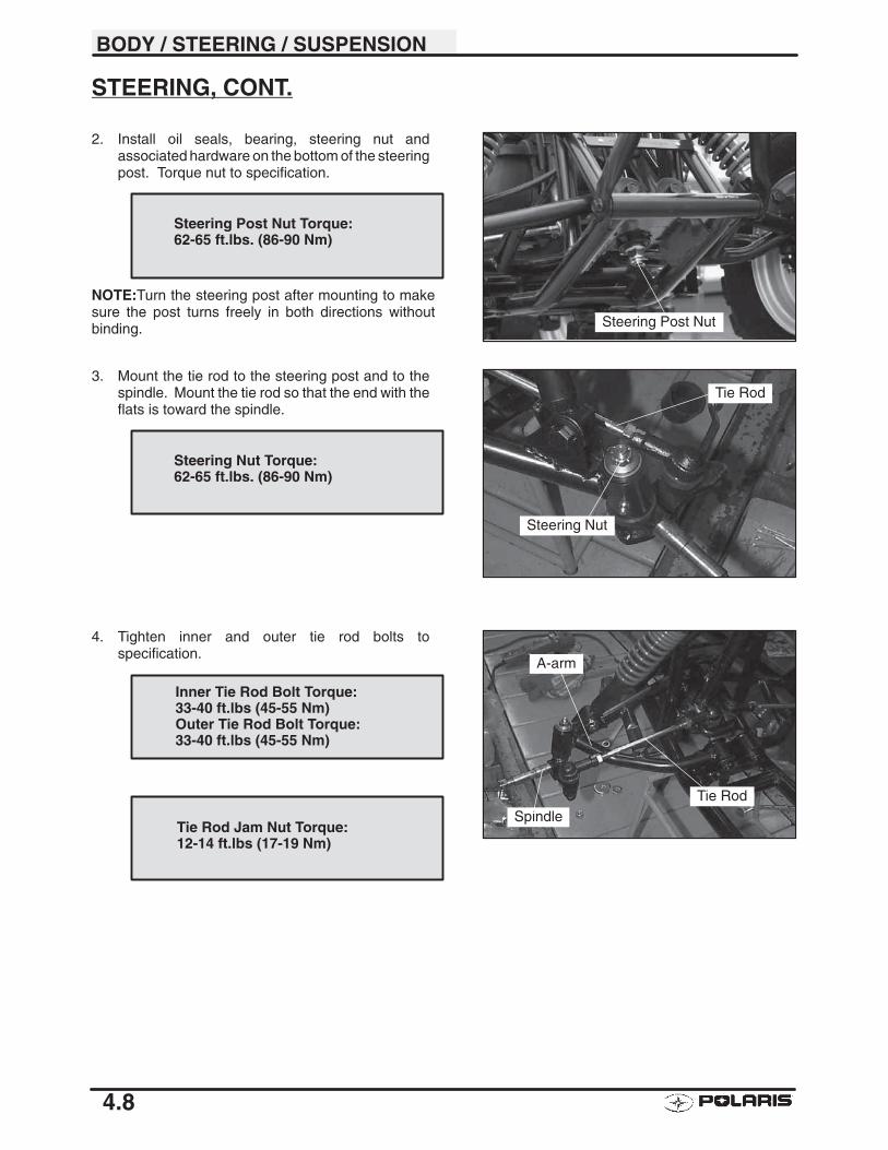
BODY / STEERING / SUSPENSION
4.8
STEERING, CONT.
2. Install oil seals, bearing, steering nut andassociated hardware on the bottom of the steeringpost. Torque nut to specification.
NOTE:Turn the steering post after mounting to makesure the post turns freely in both directions withoutbinding.
3. Mount the tie rod to the steering post and to thespindle. Mount the tie rod so that the end with theflats is toward the spindle.
4. Tighten inner and outer tie rod bolts tospecification.
Steering Post Nut
Steering Post Nut Torque:62-65 ft.lbs. (86-90 Nm)
Tie Rod
Steering Nut
Steering Nut Torque:62-65 ft.lbs. (86-90 Nm)
Tie Rod
A-arm
Spindle
Inner Tie Rod Bolt Torque:33-40 ft.lbs (45-55 Nm)Outer Tie Rod Bolt Torque:33-40 ft.lbs (45-55 Nm)
Tie Rod Jam Nut Torque:12-14 ft.lbs (17-19 Nm)
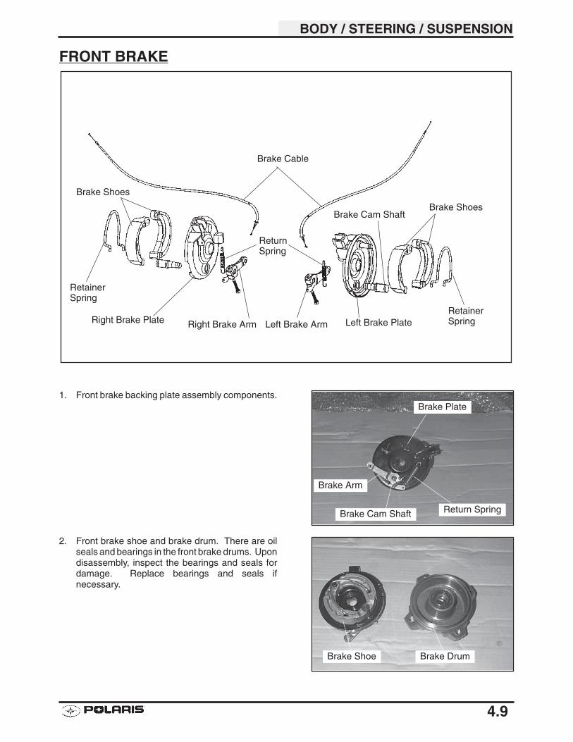
BODY / STEERING / SUSPENSION
4.9
FRONT BRAKE
1. Front brake backing plate assembly components.
2. Front brake shoe and brake drum. There are oilseals and bearings in the front brake drums. Upondisassembly, inspect the bearings and seals fordamage. Replace bearings and seals ifnecessary.
Brake Arm
Brake Cam Shaft Return Spring
Brake Plate
Brake Shoe Brake Drum
Right Brake Plate Left Brake PlateRight Brake Arm Left Brake Arm
Brake Shoes
RetainerSpring
RetainerSpring
Brake Shoes
ReturnSpring
Brake Cable
Brake Cam Shaft
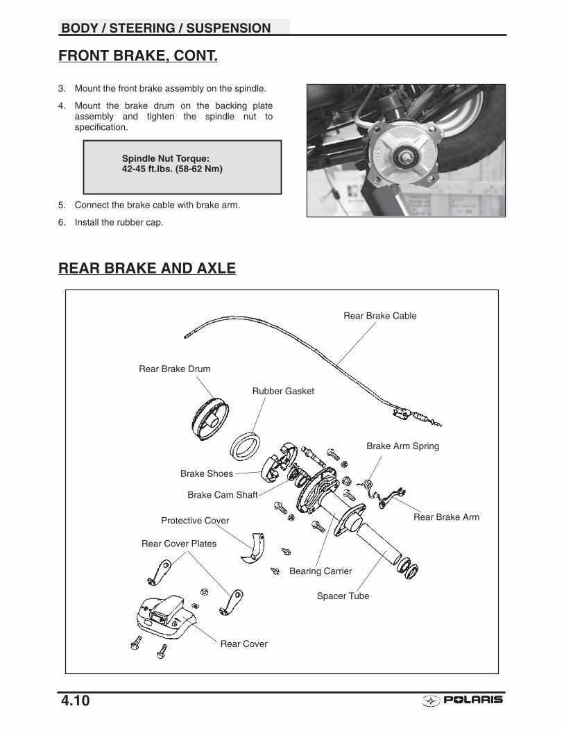
BODY / STEERING / SUSPENSION
4.10
FRONT BRAKE, CONT.
3. Mount the front brake assembly on the spindle.
4. Mount the brake drum on the backing plateassembly and tighten the spindle nut tospecification.
5. Connect the brake cable with brake arm.
6. Install the rubber cap.
REAR BRAKE AND AXLE
Spindle Nut Torque:42-45 ft.lbs. (58-62 Nm)
Rear Brake Cable
Rear Brake Drum
Rubber Gasket
Brake Shoes
Brake Cam Shaft
Bearing Carrier
Brake Arm Spring
Rear Brake Arm
Spacer Tube
Protective Cover
Rear Cover Plates
Rear Cover
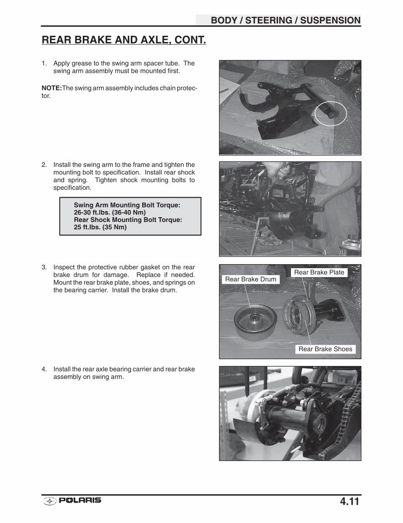
BODY / STEERING / SUSPENSION
4.11
REAR BRAKE AND AXLE, CONT.
1. Apply grease to the swing arm spacer tube. Theswing arm assembly must be mounted first.
NOTE:The swing arm assembly includes chain protec-tor.
2. Install the swing arm to the frame and tighten themounting bolt to specification. Install rear shockand spring. Tighten shock mounting bolts tospecification.
3. Inspect the protective rubber gasket on the rearbrake drum for damage. Replace if needed.Mount the rear brake plate, shoes, and springs onthe bearing carrier. Install the brake drum.
4. Install the rear axle bearing carrier and rear brakeassembly on swing arm.
Swing Arm Mounting Bolt Torque:26-30 ft.lbs. (36-40 Nm)Rear Shock Mounting Bolt Torque:25 ft.lbs. (35 Nm)
Rear Brake Plate
Rear Brake Shoes
Rear Brake Drum
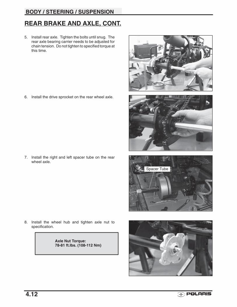
BODY / STEERING / SUSPENSION
4.12
REAR BRAKE AND AXLE, CONT.
5. Install rear axle. Tighten the bolts until snug. Therear axle bearing carrier needs to be adjusted forchain tension. Do not tighten to specified torque atthis time.
6. Install the drive sprocket on the rear wheel axle.
7. Install the right and left spacer tube on the rearwheel axle.
8. Install the wheel hub and tighten axle nut tospecification.
Spacer Tube
Axle Nut Torque:78-81 ft.lbs. (108-112 Nm)
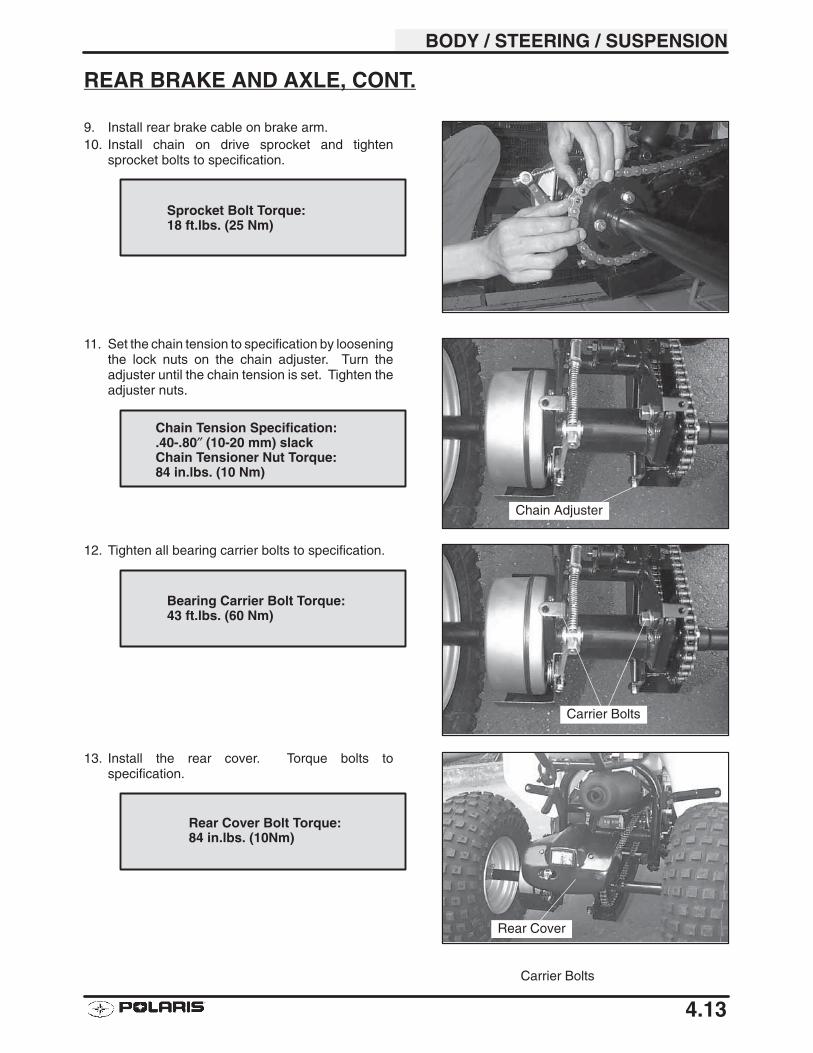
BODY / STEERING / SUSPENSION
4.13
REAR BRAKE AND AXLE, CONT.
9. Install rear brake cable on brake arm.10. Install chain on drive sprocket and tighten
sprocket bolts to specification.
11. Set the chain tension to specification by looseningthe lock nuts on the chain adjuster. Turn theadjuster until the chain tension is set. Tighten theadjuster nuts.
12. Tighten all bearing carrier bolts to specification.
13. Install the rear cover. Torque bolts tospecification.
Sprocket Bolt Torque:18 ft.lbs. (25 Nm)
Chain Adjuster
Chain Tension Specification:.40-.80″ (10-20 mm) slackChain Tensioner Nut Torque:84 in.lbs. (10 Nm)
Carrier Bolts
Carrier Bolts
Bearing Carrier Bolt Torque:43 ft.lbs. (60 Nm)
Rear Cover
Rear Cover Bolt Torque:84 in.lbs. (10Nm)
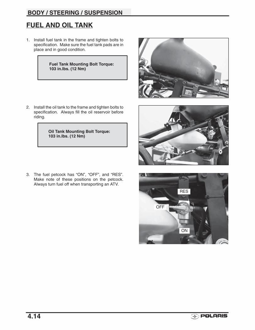
BODY / STEERING / SUSPENSION
4.14
FUEL AND OIL TANK
1. Install fuel tank in the frame and tighten bolts tospecification. Make sure the fuel tank pads are inplace and in good condition.
2. Install the oil tank to the frame and tighten bolts tospecification. Always fill the oil reservoir beforeriding.
3. The fuel petcock has “ON”, “OFF”, and “RES”.Make note of these positions on the petcock.Always turn fuel off when transporting an ATV.
Fuel Tank Mounting Bolt Torque:103 in.lbs. (12 Nm)
Oil Tank Mounting Bolt Torque:103 in.lbs. (12 Nm)
OFF
RES
ON
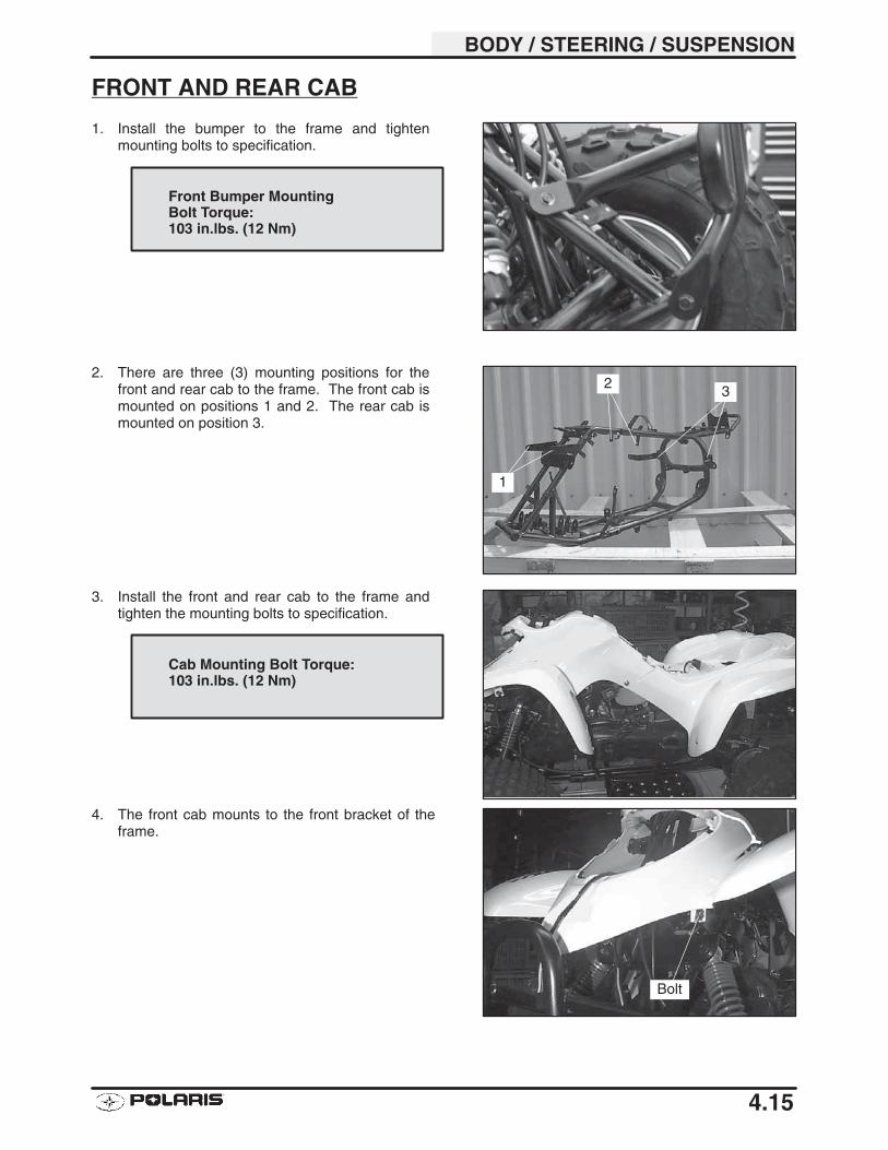
BODY / STEERING / SUSPENSION
4.15
FRONT AND REAR CAB
1. Install the bumper to the frame and tightenmounting bolts to specification.
2. There are three (3) mounting positions for thefront and rear cab to the frame. The front cab ismounted on positions 1 and 2. The rear cab ismounted on position 3.
3. Install the front and rear cab to the frame andtighten the mounting bolts to specification.
4. The front cab mounts to the front bracket of theframe.
Front Bumper MountingBolt Torque:103 in.lbs. (12 Nm)
1
2 3
Cab Mounting Bolt Torque:103 in.lbs. (12 Nm)
Bolt
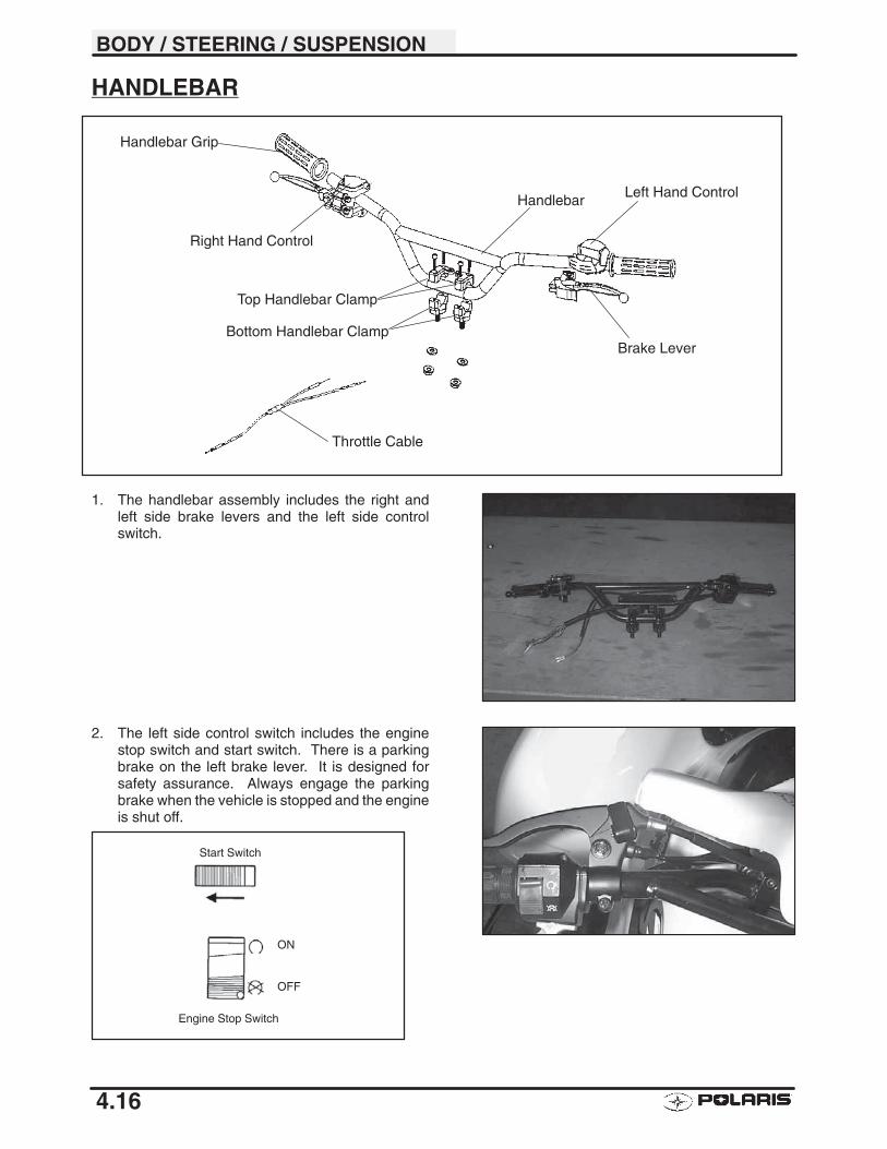
BODY / STEERING / SUSPENSION
4.16
HANDLEBAR
1. The handlebar assembly includes the right andleft side brake levers and the left side controlswitch.
2. The left side control switch includes the enginestop switch and start switch. There is a parkingbrake on the left brake lever. It is designed forsafety assurance. Always engage the parkingbrake when the vehicle is stopped and the engineis shut off.
Start Switch
Engine Stop Switch
ON
OFF
Top Handlebar Clamp
Bottom Handlebar Clamp
Handlebar
Handlebar Grip
Right Hand Control
Left Hand Control
Brake Lever
Throttle Cable
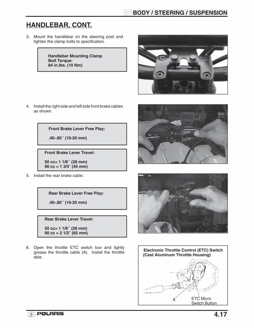
BODY / STEERING / SUSPENSION
4.17
HANDLEBAR, CONT.
3. Mount the handlebar on the steering post andtighten the clamp bolts to specification.
4. Install the right side and left side front brake cablesas shown.
5. Install the rear brake cable.
6. Open the throttle ETC switch box and lightlygrease the throttle cable (A). Install the throttleable.
Handlebar Mounting ClampBolt Torque:84 in.lbs. (10 Nm)
Front Brake Lever Free Play:
.40-.80� (10-20 mm)
Front Brake Lever Travel:
50 cc= 1 1/8� (28 mm)90 cc = 1 3/4″ (45 mm)
Rear Brake Lever Free Play:
.40-.80� (10-20 mm)
Rear Brake Lever Travel:
50 cc= 1 1/8� (28 mm)90 cc = 2 1/2″ (65 mm)
Electronic Throttle Control (ETC) Switch
ETC MicroSwitch Button
A
(Cast Aluminum Throttle Housing)
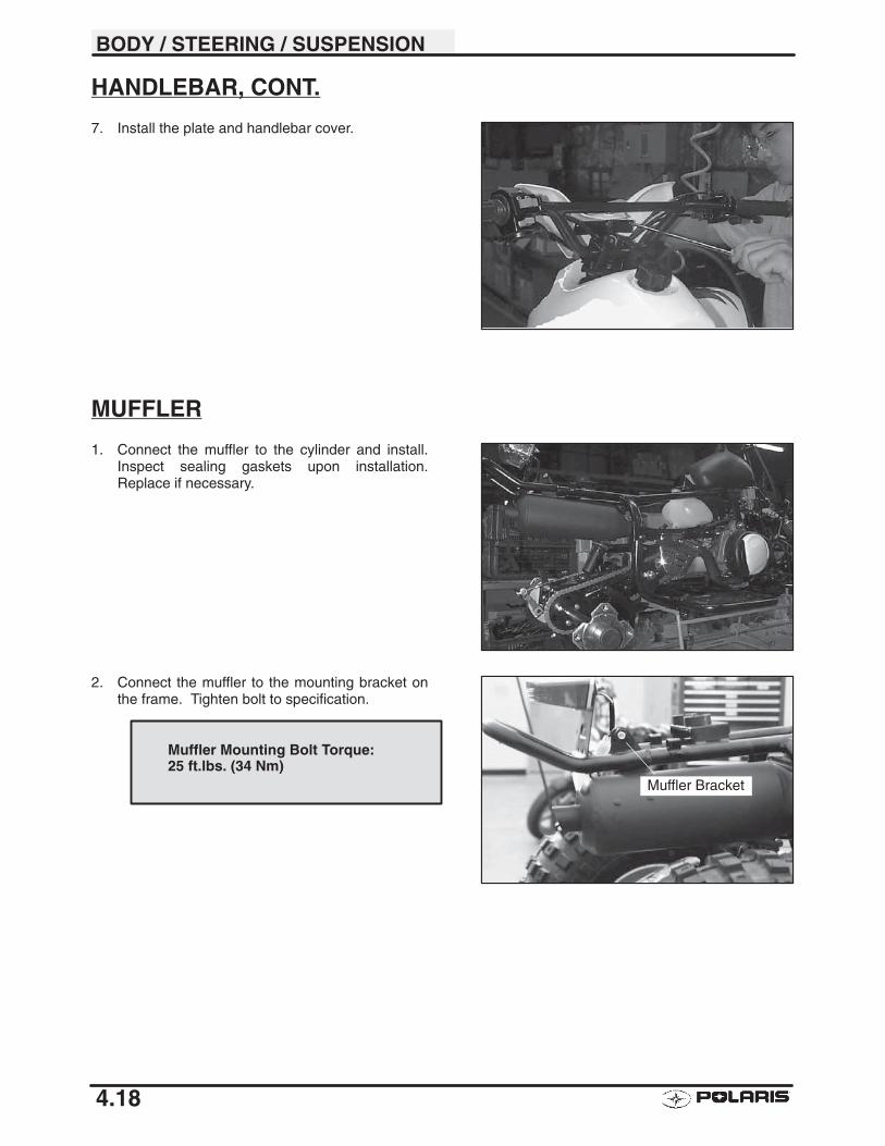
BODY / STEERING / SUSPENSION
4.18
HANDLEBAR, CONT.
7. Install the plate and handlebar cover.
MUFFLER
1. Connect the muffler to the cylinder and install.Inspect sealing gaskets upon installation.Replace if necessary.
2. Connect the muffler to the mounting bracket onthe frame. Tighten bolt to specification.
Muffler Bracket
Muffler Mounting Bolt Torque:25 ft.lbs. (34 Nm)
5
CHAPTER 5ELECTRICAL
Special Tools 5.1. . . . . . . . . . . . . . . . . . . . . . . . . . . . . . . . . . . .
Electrical Service Notes 5.1. . . . . . . . . . . . . . . . . . . . . . . . . .
Brakelight Lamp Replacement 5.1. . . . . . . . . . . . . . . . . . . . .
Battery Service / Terminals and Bolts 5.2. . . . . . . . . . . . . . .
Battery Inspection / Removal 5.3. . . . . . . . . . . . . . . . . . . . . .
Battery Installation / Testing 5.3. . . . . . . . . . . . . . . . . . . . . . .
Open Circuit Voltage Test 5.3. . . . . . . . . . . . . . . . . . . . . . . . .
Specific Gravity Test / Load Test 5.4. . . . . . . . . . . . . . . . . . .
Off Season Storage / Charging Procedure 5.5. . . . . . . . . .
Electronic Parts / Current Draw-Key Off 5.6. . . . . . . . . . . .
Charging System Testing 5.7. . . . . . . . . . . . . . . . . . . . . . . . .
Ignition System 5.8-5.9. . . . . . . . . . . . . . . . . . . . . . . . . . . . . . . . . .
Cranking Output Test 5.10. . . . . . . . . . . . . . . . . . . . . . . . . . . . .
CDI Output Test 5.10. . . . . . . . . . . . . . . . . . . . . . . . . . . . . . . . .
Charging System Testing 5.11-5.12. . . . . . . . . . . . . . . . . . . . . . . . .
Alternator Output Test (AC Amp) 5.13. . . . . . . . . . . . . . . . . . .
Starter System Troubleshooting / Voltage Drop Test 5.14. .
Starter System 5.15. . . . . . . . . . . . . . . . . . . . . . . . . . . . . . . . . .
Starter Motor Disassembly 5.16-5.17. . . . . . . . . . . . . . . . . . . . . . . .
Brush Inspection / Replacement 5.17-5.18. . . . . . . . . . . . . . . . . . .
Armature Testing 5.18. . . . . . . . . . . . . . . . . . . . . . . . . . . . . . . .
Starter Assembly 5.19. . . . . . . . . . . . . . . . . . . . . . . . . . . . . . . .
Electronic Throttle Control (ETC) 5.20. . . . . . . . . . . . . . . . . .
Ignition System Troubleshooting 5.21. . . . . . . . . . . . . . . . . . .
Wiring Diagram - Scrambler 50 5.22. . . . . . . . . . . . . . . . . . . .
Wiring Diagram - Scrambler 90 / Sportsman 90 5.23. . . . . .

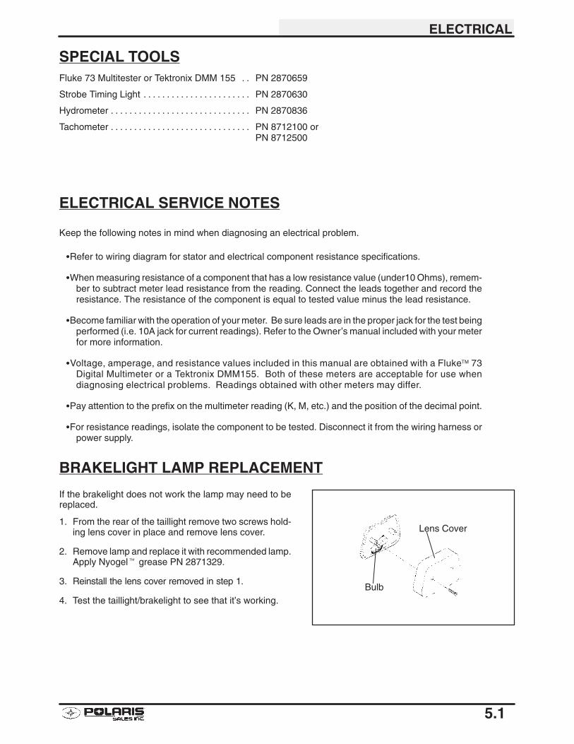
ELECTRICAL
5.1
SPECIAL TOOLSFluke 73 Multitester or Tektronix DMM 155 PN 2870659. .
Strobe Timing Light PN 2870630. . . . . . . . . . . . . . . . . . . . . . .
Hydrometer PN 2870836. . . . . . . . . . . . . . . . . . . . . . . . . . . . . .
Tachometer PN 8712100 or . . . . . . . . . . . . . . . . . . . . . . . . . . . . . . PN 8712500
ELECTRICAL SERVICE NOTES
Keep the following notes in mind when diagnosing an electrical problem.
�Refer to wiring diagram for stator and electrical component resistance specifications.
�When measuring resistance of a component that has a low resistance value (under10 Ohms), remem-ber to subtract meter lead resistance from the reading. Connect the leads together and record theresistance. The resistance of the component is equal to tested value minus the lead resistance.
�Become familiar with the operation of your meter. Be sure leads are in the proper jack for the test beingperformed (i.e. 10A jack for current readings). Refer to the Owner’s manual included with your meterfor more information.
�Voltage, amperage, and resistance values included in this manual are obtained with a Fluke™ 73Digital Multimeter or a Tektronix DMM155. Both of these meters are acceptable for use whendiagnosing electrical problems. Readings obtained with other meters may differ.
�Pay attention to the prefix on the multimeter reading (K, M, etc.) and the position of the decimal point.
�For resistance readings, isolate the component to be tested. Disconnect it from the wiring harness orpower supply.
BRAKELIGHT LAMP REPLACEMENT
If the brakelight does not work the lamp may need to bereplaced.
1. From the rear of the taillight remove two screws hold-ing lens cover in place and remove lens cover.
2. Remove lamp and replace it with recommended lamp.Apply Nyogel� grease PN 2871329.
3. Reinstall the lens cover removed in step 1.
4. Test the taillight/brakelight to see that it’s working.
Lens Cover
Bulb
ELECTRICAL
5.2
INITIAL BATTERY SERVICE
WARNINGBattery electrolyte is poisonous. It contains sulfuric acid. Seriousburns can result from contact with skin, eyes or clothing. Antidote:
External: Flush with water.
Internal: Drink large quantities of water or milk. Follow with milkof magnesia, beaten egg, or vegetable oil. Call physician immedi-ately.
Eyes: Flush with water for 15 minutes and get prompt medicalattention.
Batteries produce explosive gases. Keep sparks, flame, ciga-rettes, etc. away. Ventilate when charging or using in an enclosedspace. Always shield eyes when working near batteries. KEEPOUT OF REACH OF CHILDREN.
WARNING: The gases given off by a battery are explosive. Any spark or open flame near a battery can causean explosion which will spray battery acid on anyone close to it. If battery acid gets on anyone, wash the affectedarea with large quantities of cool water and seek immediate medical attention.
To ensure maximum service life and performance from a new battery, perform the following steps. NOTE: Do notservice the battery unless it will be put into regular service within 30 days. After initial service, add only distilledwater to the battery. Never add electrolyte after a battery has been in service.
NOTE: New Battery: Battery must be fully charged before use or battery life will be significantly reduced 10-30%of battery’s full potential.
1. Remove vent plug from vent fitting.
2. Fill battery with electrolyte to upper level marks on case.
3. Set battery aside and allow it to cool and stabilize for 30 minutes.
4. Add electrolyte to bring level back to upper level mark on case. NOTE: This is the last time that electrolyteshould be added. If the level becomes low after this point, add only distilled water.
5. Charge battery at 1/10 of its amp/hour rating. Examples: 1/10 of 9 amp battery = .9 amp; 1/10 of 14 ampbattery = 1.4 amp; 1/10 of 18 amp battery = 1.8 amp (recommended charging rates).
6. Check specific gravity of each cell with a hydrometer to assure each has a reading of 1.270 or higher.
BATTERY TERMINALS/TERMINAL BOLTSUse Polaris corrosion resistant Nyogel� grease (PN 2871329) on battery bolts. See Battery Installation on page5.3.
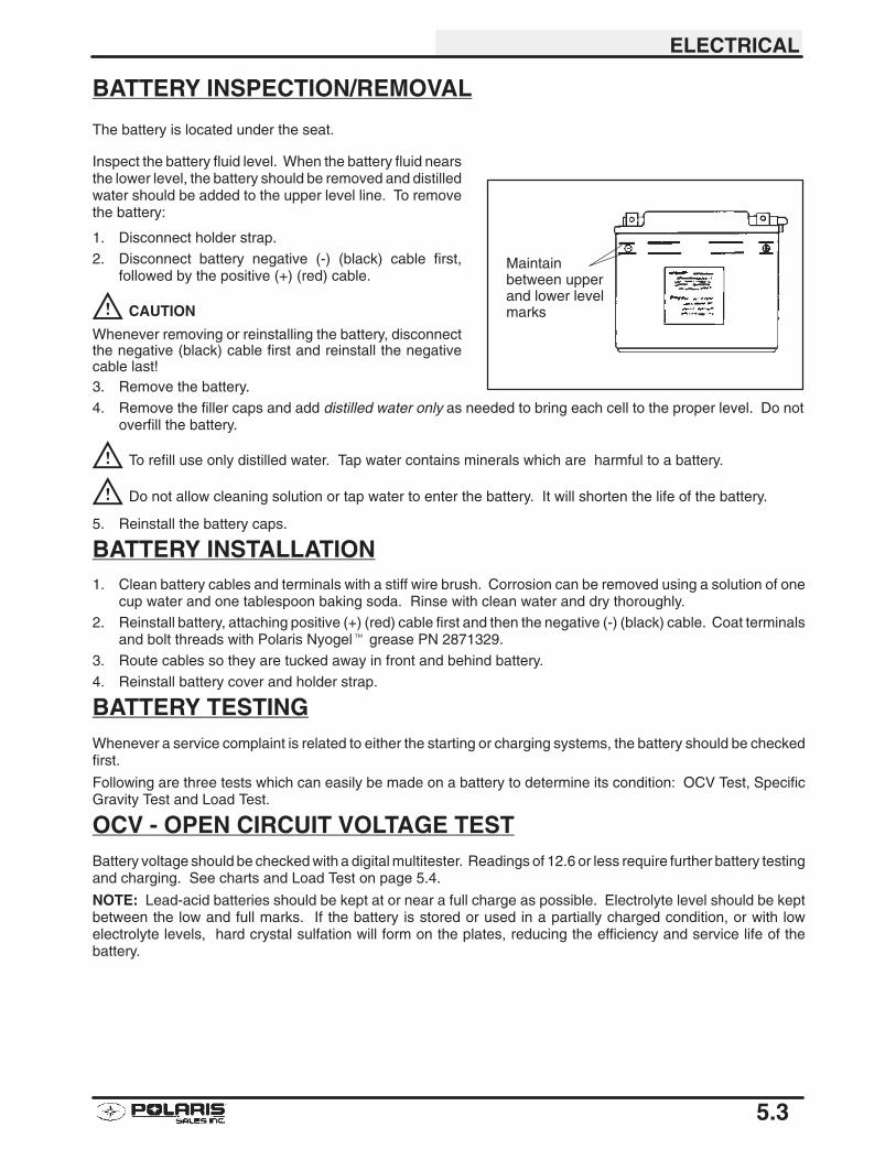
ELECTRICAL
5.3
BATTERY INSPECTION/REMOVAL
The battery is located under the seat.
Inspect the battery fluid level. When the battery fluid nearsthe lower level, the battery should be removed and distilledwater should be added to the upper level line. To removethe battery:
1. Disconnect holder strap.2. Disconnect battery negative (-) (black) cable first,
followed by the positive (+) (red) cable.
CAUTION
Whenever removing or reinstalling the battery, disconnectthe negative (black) cable first and reinstall the negativecable last!3. Remove the battery.
4. Remove the filler caps and add distilled water only as needed to bring each cell to the proper level. Do notoverfill the battery.
To refill use only distilled water. Tap water contains minerals which are harmful to a battery.
Do not allow cleaning solution or tap water to enter the battery. It will shorten the life of the battery.
5. Reinstall the battery caps.
BATTERY INSTALLATION1. Clean battery cables and terminals with a stiff wire brush. Corrosion can be removed using a solution of one
cup water and one tablespoon baking soda. Rinse with clean water and dry thoroughly.2. Reinstall battery, attaching positive (+) (red) cable first and then the negative (-) (black) cable. Coat terminals
and bolt threads with Polaris Nyogel� grease PN 2871329.
3. Route cables so they are tucked away in front and behind battery.
4. Reinstall battery cover and holder strap.
BATTERY TESTINGWhenever a service complaint is related to either the starting or charging systems, the battery should be checkedfirst.
Following are three tests which can easily be made on a battery to determine its condition: OCV Test, SpecificGravity Test and Load Test.
OCV - OPEN CIRCUIT VOLTAGE TESTBattery voltage should be checked with a digital multitester. Readings of 12.6 or less require further battery testingand charging. See charts and Load Test on page 5.4.
NOTE: Lead-acid batteries should be kept at or near a full charge as possible. Electrolyte level should be keptbetween the low and full marks. If the battery is stored or used in a partially charged condition, or with lowelectrolyte levels, hard crystal sulfation will form on the plates, reducing the efficiency and service life of thebattery.
Maintainbetween upperand lower levelmarks
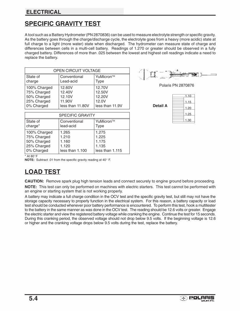
ELECTRICAL
5.4
SPECIFIC GRAVITY TEST
A tool such as a Battery Hydrometer (PN 2870836) can be used to measure electrolyte strength or specific gravity.As the battery goes through the charge/discharge cycle, the electrolyte goes from a heavy (more acidic) state atfull charge to a light (more water) state when discharged. The hydrometer can measure state of charge anddifferences between cells in a multi-cell battery. Readings of 1.270 or greater should be observed in a fullycharged battery. Differences of more than .025 between the lowest and highest cell readings indicate a need toreplace the battery.
OPEN CIRCUIT VOLTAGE
State ofcharge
ConventionalLead-acid
YuMicron™Type
100% Charged75% Charged50% Charged25% Charged0% Charged
12.60V12.40V12.10V11.90Vless than 11.80V
12.70V12.50V12.20V12.0Vless than 11.9V
SPECIFIC GRAVITY
State ofcharge*
Conventionallead-acid
YuMicron™Type
100% Charged75% Charged50% Charged25% Charged0% Charged
1.2651.2101.1601.120less than 1.100
1.2751.2251.1751.135less than 1.115
* At 80�FNOTE: Subtract .01 from the specific gravity reading at 40� F.
LOAD TESTCAUTION: Remove spark plug high tension leads and connect securely to engine ground before proceeding.
NOTE: This test can only be performed on machines with electric starters. This test cannot be performed withan engine or starting system that is not working properly.A battery may indicate a full charge condition in the OCV test and the specific gravity test, but still may not have thestorage capacity necessary to properly function in the electrical system. For this reason, a battery capacity or loadtest should be conducted whenever poor battery performance is encountered. To perform this test, hook a multitesterto the battery in the same manner as was done in the OCV test. The reading should be 12.6 volts or greater. Engagethe electric starter and view the registered battery voltage while cranking the engine. Continue the test for 15 seconds.During this cranking period, the observed voltage should not drop below 9.5 volts. If the beginning voltage is 12.6or higher and the cranking voltage drops below 9.5 volts during the test, replace the battery.
Detail A
1.10
1.15
1.20
1.25
1.30
Polaris PN 2870876
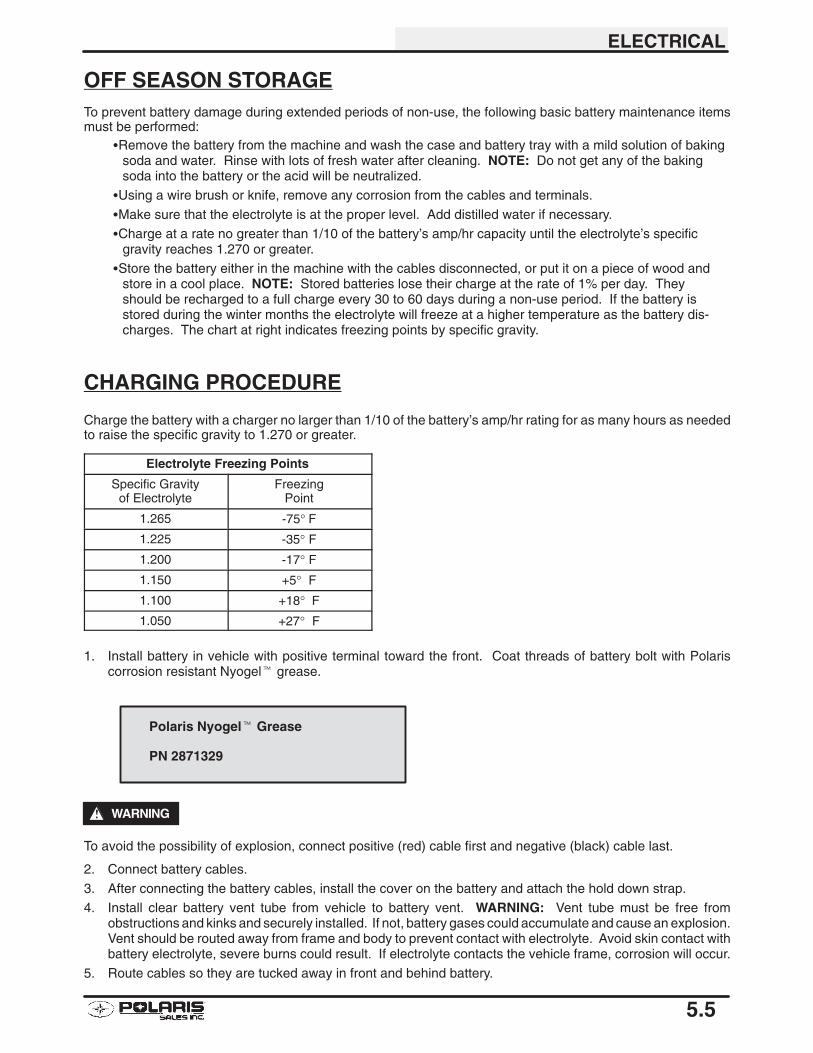
ELECTRICAL
5.5
OFF SEASON STORAGETo prevent battery damage during extended periods of non-use, the following basic battery maintenance itemsmust be performed:
�Remove the battery from the machine and wash the case and battery tray with a mild solution of bakingsoda and water. Rinse with lots of fresh water after cleaning. NOTE: Do not get any of the bakingsoda into the battery or the acid will be neutralized.
�Using a wire brush or knife, remove any corrosion from the cables and terminals.
�Make sure that the electrolyte is at the proper level. Add distilled water if necessary.
�Charge at a rate no greater than 1/10 of the battery’s amp/hr capacity until the electrolyte’s specificgravity reaches 1.270 or greater.
�Store the battery either in the machine with the cables disconnected, or put it on a piece of wood andstore in a cool place. NOTE: Stored batteries lose their charge at the rate of 1% per day. Theyshould be recharged to a full charge every 30 to 60 days during a non-use period. If the battery isstored during the winter months the electrolyte will freeze at a higher temperature as the battery dis-charges. The chart at right indicates freezing points by specific gravity.
CHARGING PROCEDURE
Charge the battery with a charger no larger than 1/10 of the battery’s amp/hr rating for as many hours as neededto raise the specific gravity to 1.270 or greater.
Electrolyte Freezing Points
Specific Gravityof Electrolyte
FreezingPoint
1.265 -75° F
1.225 -35° F1.200 -17° F1.150 +5° F1.100 +18° F
1.050 +27° F
1. Install battery in vehicle with positive terminal toward the front. Coat threads of battery bolt with Polariscorrosion resistant Nyogel� grease.
WARNING
To avoid the possibility of explosion, connect positive (red) cable first and negative (black) cable last.
2. Connect battery cables.
3. After connecting the battery cables, install the cover on the battery and attach the hold down strap.
4. Install clear battery vent tube from vehicle to battery vent. WARNING: Vent tube must be free fromobstructions and kinks and securely installed. If not, battery gases could accumulate and cause an explosion.Vent should be routed away from frame and body to prevent contact with electrolyte. Avoid skin contact withbattery electrolyte, severe burns could result. If electrolyte contacts the vehicle frame, corrosion will occur.
5. Route cables so they are tucked away in front and behind battery.
Polaris Nyogel� Grease
PN 2871329
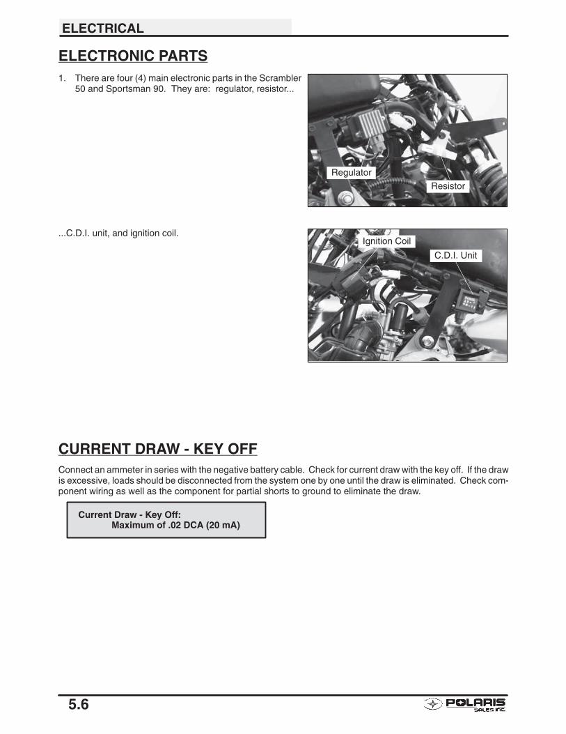
ELECTRICAL
5.6
ELECTRONIC PARTS1. There are four (4) main electronic parts in the Scrambler
50 and Sportsman 90. They are: regulator, resistor...
...C.D.I. unit, and ignition coil.
CURRENT DRAW - KEY OFFConnect an ammeter in series with the negative battery cable. Check for current draw with the key off. If the drawis excessive, loads should be disconnected from the system one by one until the draw is eliminated. Check com-ponent wiring as well as the component for partial shorts to ground to eliminate the draw.
Current Draw - Key Off:Maximum of .02 DCA (20 mA)
Regulator
Resistor
C.D.I. Unit Ignition CoilC.D.I. Unit
Ignition Coil
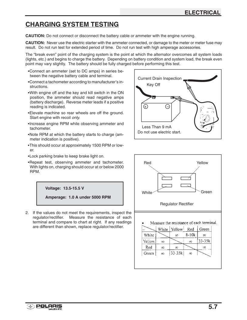
ELECTRICAL
5.7
CHARGING SYSTEM TESTING
CAUTION: Do not connect or disconnect the battery cable or ammeter with the engine running.
CAUTION: Never use the electric starter with the ammeter connected, or damage to the meter or meter fuse mayresult. Do not run test for extended period of time. Do not run test with high amperage accessories.
The “break even” point of the charging system is the point at which the alternator overcomes all system loads(lights, etc.) and begins to charge the battery. Depending on battery condition and system load, the break evenpoint may vary slightly. The battery should be fully charged before performing this test.
�Connect an ammeter (set to DC amps) in series be-tween the negative battery cable and terminal.
�Connect a tachometer according to manufacturer’s in-structions.
�With engine off and the key and kill switch in the ONposition, the ammeter should read negative amps(battery discharge). Reverse meter leads if a positivereading is indicated.
�Elevate machine so rear wheels are off the ground.Start engine with recoil only.
�Increase engine RPM while observing ammeter andtachometer.
�Note RPM at which the battery starts to charge (am-meter indication is positive).
�This should occur at approximately 1500 RPM or low-er.
�Lock parking brake to keep brake light on.
�Repeat test, observing ammeter and tachometer.With lights on, charging should occur at or below 2000RPM.
2. If the values do not meet the requirements, inspect theregulator/rectifier. Measure the resistance of eachterminal and compare to chart at right. If any readingsare different than shown, replace regulator/rectifier.
Do not use electric start.
–+
Current Drain Inspection
Key Off
Less Than 9 mA
Red
White
Yellow
Green
Regulator Rectifier
Voltage: 13.5-15.5 V
Amperage: 1.0 A under 5000 RPM
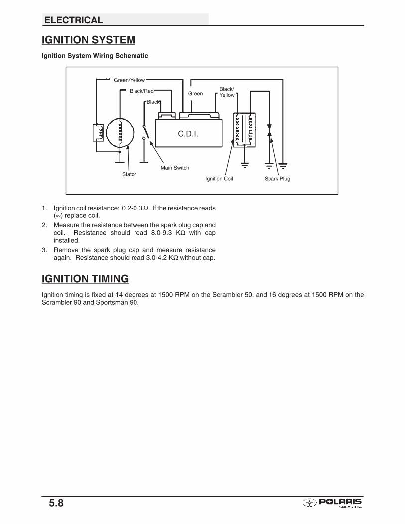
ELECTRICAL
5.8
IGNITION SYSTEMIgnition System Wiring Schematic
Stator
Green/Yellow
Black/Red
Black
Main Switch
GreenBlack/Yellow
Ignition Coil Spark Plug
C.D.I.
1. Ignition coil resistance: 0.2-0.3 Ω. If the resistance reads(∞) replace coil.
2. Measure the resistance between the spark plug cap andcoil. Resistance should read 8.0-9.3 KΩ with capinstalled.
3. Remove the spark plug cap and measure resistanceagain. Resistance should read 3.0-4.2 KΩ without cap.
IGNITION TIMINGIgnition timing is fixed at 14 degrees at 1500 RPM on the Scrambler 50, and 16 degrees at 1500 RPM on theScrambler 90 and Sportsman 90.
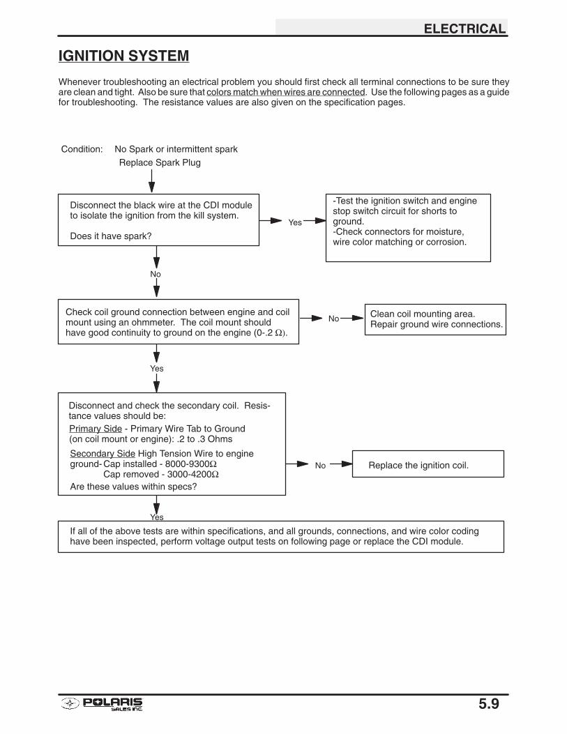
ELECTRICAL
5.9
IGNITION SYSTEM
Whenever troubleshooting an electrical problem you should first check all terminal connections to be sure theyare clean and tight. Also be sure that colors match when wires are connected. Use the following pages as a guidefor troubleshooting. The resistance values are also given on the specification pages.
Condition: No Spark or intermittent spark
Disconnect the black wire at the CDI moduleto isolate the ignition from the kill system.
Does it have spark?
-Test the ignition switch and enginestop switch circuit for shorts toground.-Check connectors for moisture,wire color matching or corrosion.
Yes
No
Yes
Check coil ground connection between engine and coilmount using an ohmmeter. The coil mount shouldhave good continuity to ground on the engine (0-.2 Ω).
Replace Spark Plug
Disconnect and check the secondary coil. Resis-tance values should be:Primary Side - Primary Wire Tab to Ground(on coil mount or engine): .2 to .3 Ohms
Secondary Side High Tension Wire to engineground- Cap installed - 8000-9300Ω
Cap removed - 3000-4200ΩAre these values within specs?
Replace the ignition coil.No
Yes
If all of the above tests are within specifications, and all grounds, connections, and wire color codinghave been inspected, perform voltage output tests on following page or replace the CDI module.
Clean coil mounting area.Repair ground wire connections.
No
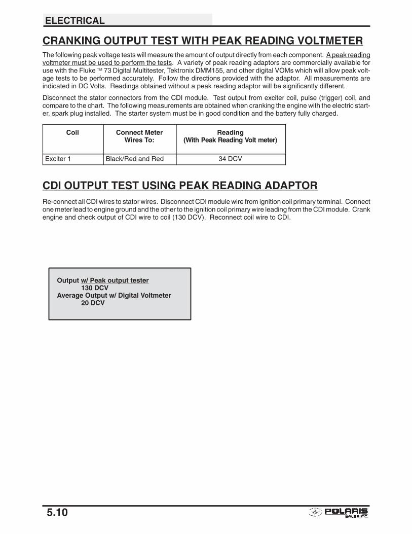
ELECTRICAL
5.10
CRANKING OUTPUT TEST WITH PEAK READING VOLTMETERThe following peak voltage tests will measure the amount of output directly from each component. A peak readingvoltmeter must be used to perform the tests. A variety of peak reading adaptors are commercially available foruse with the Fluke ™ 73 Digital Multitester, Tektronix DMM155, and other digital VOMs which will allow peak volt-age tests to be performed accurately. Follow the directions provided with the adaptor. All measurements areindicated in DC Volts. Readings obtained without a peak reading adaptor will be significantly different.
Disconnect the stator connectors from the CDI module. Test output from exciter coil, pulse (trigger) coil, andcompare to the chart. The following measurements are obtained when cranking the engine with the electric start-er, spark plug installed. The starter system must be in good condition and the battery fully charged.
Coil Connect MeterWires To:
Reading(With Peak Reading Volt meter)
Exciter 1 Black/Red and Red 34 DCV
CDI OUTPUT TEST USING PEAK READING ADAPTORRe-connect all CDI wires to stator wires. Disconnect CDI module wire from ignition coil primary terminal. Connectone meter lead to engine ground and the other to the ignition coil primary wire leading from the CDI module. Crankengine and check output of CDI wire to coil (130 DCV). Reconnect coil wire to CDI.
Output w/ Peak output tester130 DCV
Average Output w/ Digital Voltmeter20 DCV
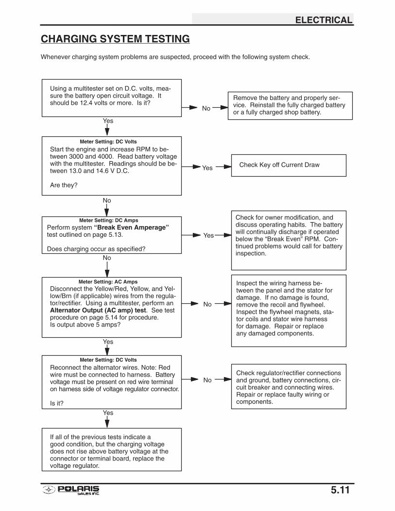
ELECTRICAL
5.11
CHARGING SYSTEM TESTING
Whenever charging system problems are suspected, proceed with the following system check.
Check for owner modification, anddiscuss operating habits. The batterywill continually discharge if operatedbelow the “Break Even” RPM. Con-tinued problems would call for batteryinspection.
Disconnect the Yellow/Red, Yellow, and Yel-low/Brn (if applicable) wires from the regula-tor/rectifier. Using a multitester, perform anAlternator Output (AC amp) test. See testprocedure on page 5.14 for procedure.Is output above 5 amps?
Inspect the wiring harness be-tween the panel and the stator fordamage. If no damage is found,remove the recoil and flywheel.Inspect the flywheel magnets, sta-tor coils and stator wire harnessfor damage. Repair or replaceany damaged components.
Reconnect the alternator wires. Note: Redwire must be connected to harness. Batteryvoltage must be present on red wire terminalon harness side of voltage regulator connector.
Is it?
Check regulator/rectifier connectionsand ground, battery connections, cir-cuit breaker and connecting wires.Repair or replace faulty wiring orcomponents.
If all of the previous tests indicate agood condition, but the charging voltagedoes not rise above battery voltage at theconnector or terminal board, replace thevoltage regulator.
No
Yes
No
Yes
Perform system “Break Even Amperage”test outlined on page 5.13.
Does charging occur as specified?
Using a multitester set on D.C. volts, mea-sure the battery open circuit voltage. Itshould be 12.4 volts or more. Is it?
Remove the battery and properly ser-vice. Reinstall the fully charged batteryor a fully charged shop battery.
Start the engine and increase RPM to be-tween 3000 and 4000. Read battery voltagewith the multitester. Readings should be be-tween 13.0 and 14.6 V D.C.
Are they?
No
Yes
No
Yes Check Key off Current Draw
No
Meter Setting: AC Amps
Meter Setting: DC Amps
Meter Setting: DC Volts
Meter Setting: DC Volts
Yes
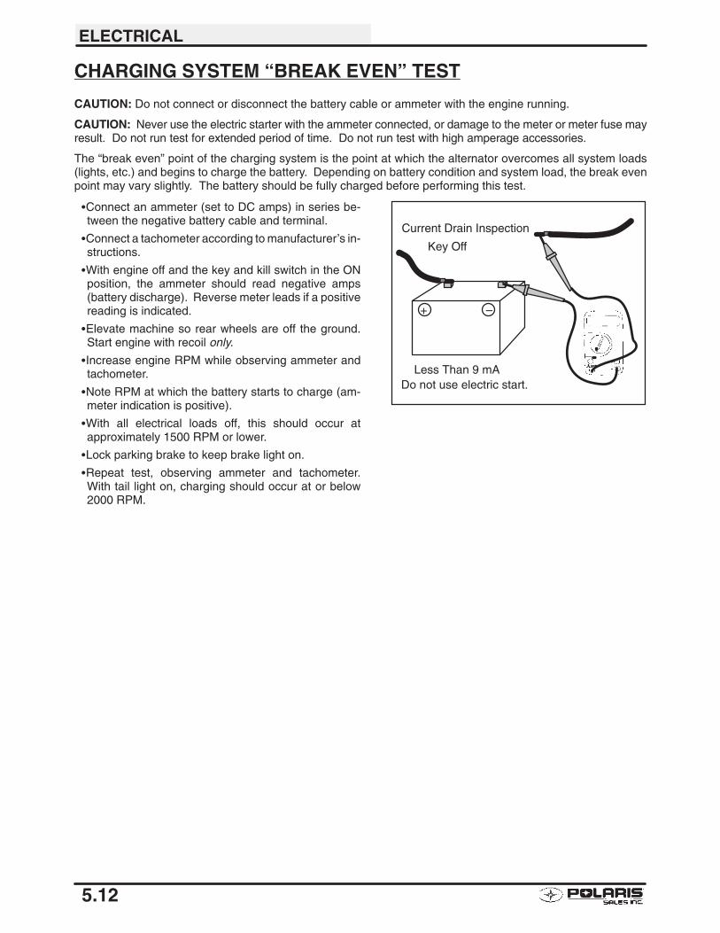
ELECTRICAL
5.12
CHARGING SYSTEM “BREAK EVEN” TEST
CAUTION: Do not connect or disconnect the battery cable or ammeter with the engine running.
CAUTION: Never use the electric starter with the ammeter connected, or damage to the meter or meter fuse mayresult. Do not run test for extended period of time. Do not run test with high amperage accessories.
The “break even” point of the charging system is the point at which the alternator overcomes all system loads(lights, etc.) and begins to charge the battery. Depending on battery condition and system load, the break evenpoint may vary slightly. The battery should be fully charged before performing this test.
�Connect an ammeter (set to DC amps) in series be-tween the negative battery cable and terminal.
�Connect a tachometer according to manufacturer’s in-structions.
�With engine off and the key and kill switch in the ONposition, the ammeter should read negative amps(battery discharge). Reverse meter leads if a positivereading is indicated.
�Elevate machine so rear wheels are off the ground.Start engine with recoil only.
�Increase engine RPM while observing ammeter andtachometer.
�Note RPM at which the battery starts to charge (am-meter indication is positive).
�With all electrical loads off, this should occur atapproximately 1500 RPM or lower.
�Lock parking brake to keep brake light on.
�Repeat test, observing ammeter and tachometer.With tail light on, charging should occur at or below2000 RPM.
Do not use electric start.
–+
Current Drain Inspection
Key Off
Less Than 9 mA
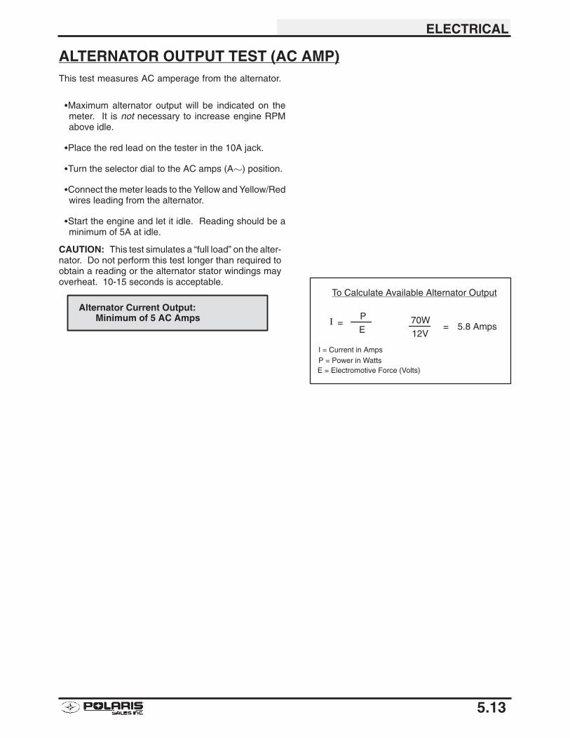
ELECTRICAL
5.13
ALTERNATOR OUTPUT TEST (AC AMP)This test measures AC amperage from the alternator.
�Maximum alternator output will be indicated on themeter. It is not necessary to increase engine RPMabove idle.
�Place the red lead on the tester in the 10A jack.
�Turn the selector dial to the AC amps (A�) position.
�Connect the meter leads to the Yellow and Yellow/Redwires leading from the alternator.
�Start the engine and let it idle. Reading should be aminimum of 5A at idle.
CAUTION: This test simulates a “full load” on the alter-nator. Do not perform this test longer than required toobtain a reading or the alternator stator windings mayoverheat. 10-15 seconds is acceptable.
Alternator Current Output:Minimum of 5 AC Amps
To Calculate Available Alternator Output
70W12V
= 5.8 Amps� =PE
I = Current in AmpsP = Power in WattsE = Electromotive Force (Volts)
ELECTRICAL
5.14
STARTER SYSTEM TROUBLESHOOTINGStarter Motor Does Not Turn
�Battery discharged - low specific gravity�Loose or faulty battery cables or corroded connections (see Voltage Drop Tests)
�Related wiring loose, disconnected, or corroded
�Poor ground connections at battery cable, starter motor or starter solenoid (see Voltage DropTests)
�Faulty starter button
�Faulty ignition switch (Do other systems function?)
�Faulty starter solenoid or starter motor.
�Engine problem - seized or binding (Can engine be rotated easily with recoil starter?)
Starter Motor Turns Over Slowly
�Battery discharged - low specific gravity
�Excessive circuit resistance - poor connections (see Voltage Drop Test below)
�Engine problem - seized or binding (Can engine be rotated easily with recoil starter?)
�Faulty or worn brushes in starter motor
�Automatic compression release inoperative
Starter Motor Turns - Engine Does Not Rotate
�Faulty starter drive�Faulty starter drive gears or starter motor gear
�Faulty flywheel gear or loose flywheel
VOLTAGE DROP TESTThe Voltage Drop Test is used to test for bad connections. When performing the test, you are testing the amountof voltage drop through the connection. A poor or corroded connection will appear as a high voltage reading.Voltage shown on the meter when testing connections should not exceed .1 VDC per connection or component.
To perform the test, place the meter on DC volts and place the meter leads across the connection to betested. Refer to the chart on next page to perform voltage drop tests on the starter system.
Voltage should not exceed:.1 DC volts per connection
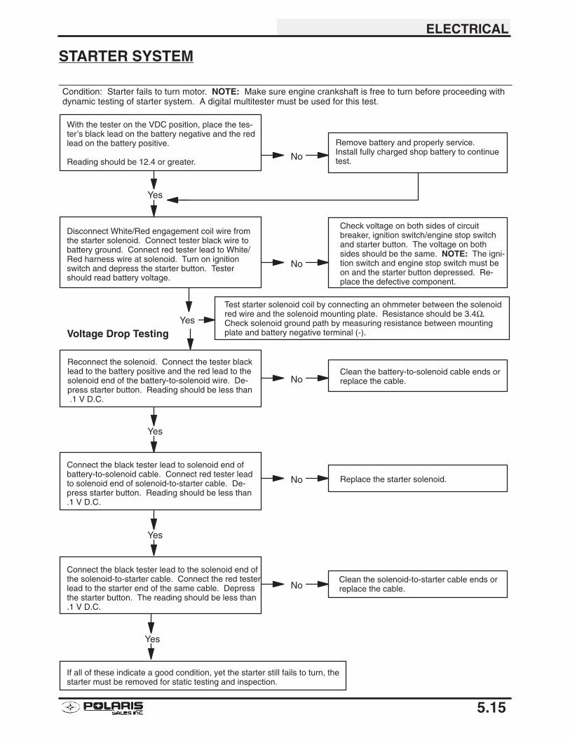
ELECTRICAL
5.15
STARTER SYSTEM
Condition: Starter fails to turn motor. NOTE: Make sure engine crankshaft is free to turn before proceeding withdynamic testing of starter system. A digital multitester must be used for this test.
With the tester on the VDC position, place the tes-ter’s black lead on the battery negative and the redlead on the battery positive.
Reading should be 12.4 or greater.
Remove battery and properly service.Install fully charged shop battery to continuetest.
Disconnect White/Red engagement coil wire fromthe starter solenoid. Connect tester black wire tobattery ground. Connect red tester lead to White/Red harness wire at solenoid. Turn on ignitionswitch and depress the starter button. Testershould read battery voltage.
Check voltage on both sides of circuitbreaker, ignition switch/engine stop switchand starter button. The voltage on bothsides should be the same. NOTE: The igni-tion switch and engine stop switch must beon and the starter button depressed. Re-place the defective component.
Reconnect the solenoid. Connect the tester blacklead to the battery positive and the red lead to thesolenoid end of the battery-to-solenoid wire. De-press starter button. Reading should be less than .1 V D.C.
Clean the battery-to-solenoid cable ends orreplace the cable.
Connect the black tester lead to solenoid end ofbattery-to-solenoid cable. Connect red tester leadto solenoid end of solenoid-to-starter cable. De-press starter button. Reading should be less than.1 V D.C.
Replace the starter solenoid.
Connect the black tester lead to the solenoid end ofthe solenoid-to-starter cable. Connect the red testerlead to the starter end of the same cable. Depressthe starter button. The reading should be less than.1 V D.C.
Clean the solenoid-to-starter cable ends orreplace the cable.
No
Yes
No
No
Yes
No
Yes
If all of these indicate a good condition, yet the starter still fails to turn, thestarter must be removed for static testing and inspection.
No
Yes
Test starter solenoid coil by connecting an ohmmeter between the solenoidred wire and the solenoid mounting plate. Resistance should be 3.4Ω.Check solenoid ground path by measuring resistance between mountingplate and battery negative terminal (-).Voltage Drop Testing
Yes
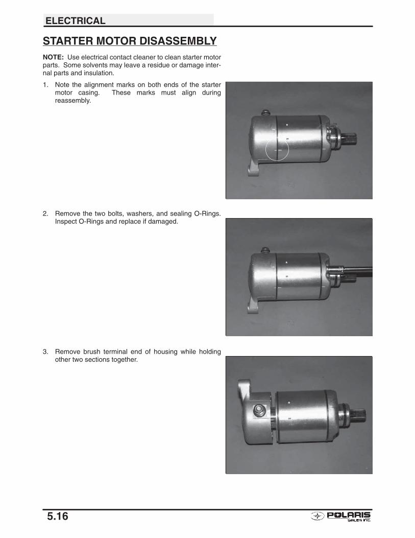
ELECTRICAL
5.16
STARTER MOTOR DISASSEMBLYNOTE: Use electrical contact cleaner to clean starter motorparts. Some solvents may leave a residue or damage inter-nal parts and insulation.
1. Note the alignment marks on both ends of the startermotor casing. These marks must align duringreassembly.
2. Remove the two bolts, washers, and sealing O-Rings.Inspect O-Rings and replace if damaged.
3. Remove brush terminal end of housing while holdingother two sections together.
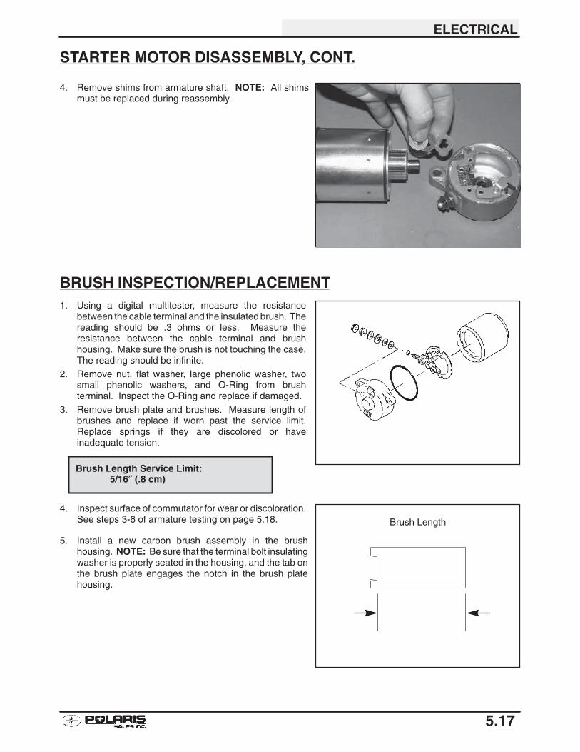
ELECTRICAL
5.17
STARTER MOTOR DISASSEMBLY, CONT.
4. Remove shims from armature shaft. NOTE: All shimsmust be replaced during reassembly.
BRUSH INSPECTION/REPLACEMENT1. Using a digital multitester, measure the resistance
between the cable terminal and the insulated brush. Thereading should be .3 ohms or less. Measure theresistance between the cable terminal and brushhousing. Make sure the brush is not touching the case.The reading should be infinite.
2. Remove nut, flat washer, large phenolic washer, twosmall phenolic washers, and O-Ring from brushterminal. Inspect the O-Ring and replace if damaged.
3. Remove brush plate and brushes. Measure length ofbrushes and replace if worn past the service limit.Replace springs if they are discolored or haveinadequate tension.
4. Inspect surface of commutator for wear or discoloration.See steps 3-6 of armature testing on page 5.18.
5. Install a new carbon brush assembly in the brushhousing. NOTE: Be sure that the terminal bolt insulatingwasher is properly seated in the housing, and the tab onthe brush plate engages the notch in the brush platehousing.
Brush Length Service Limit:5/16″ (.8 cm)
Brush Length
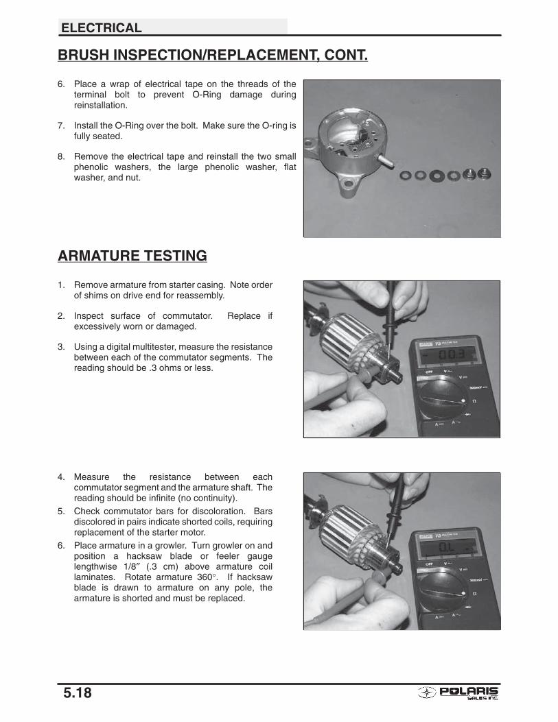
ELECTRICAL
5.18
BRUSH INSPECTION/REPLACEMENT, CONT.
6. Place a wrap of electrical tape on the threads of theterminal bolt to prevent O-Ring damage duringreinstallation.
7. Install the O-Ring over the bolt. Make sure the O-ring isfully seated.
8. Remove the electrical tape and reinstall the two smallphenolic washers, the large phenolic washer, flatwasher, and nut.
ARMATURE TESTING
1. Remove armature from starter casing. Note orderof shims on drive end for reassembly.
2. Inspect surface of commutator. Replace ifexcessively worn or damaged.
3. Using a digital multitester, measure the resistancebetween each of the commutator segments. Thereading should be .3 ohms or less.
4. Measure the resistance between eachcommutator segment and the armature shaft. Thereading should be infinite (no continuity).
5. Check commutator bars for discoloration. Barsdiscolored in pairs indicate shorted coils, requiringreplacement of the starter motor.
6. Place armature in a growler. Turn growler on andposition a hacksaw blade or feeler gaugelengthwise 1/8″ (.3 cm) above armature coillaminates. Rotate armature 360°. If hacksawblade is drawn to armature on any pole, thearmature is shorted and must be replaced.
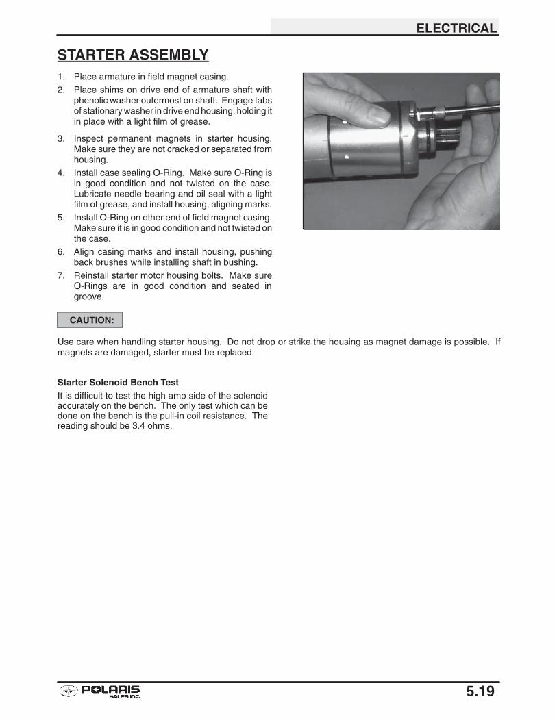
ELECTRICAL
5.19
STARTER ASSEMBLY1. Place armature in field magnet casing.
2. Place shims on drive end of armature shaft withphenolic washer outermost on shaft. Engage tabsof stationary washer in drive end housing, holding itin place with a light film of grease.
3. Inspect permanent magnets in starter housing.Make sure they are not cracked or separated fromhousing.
4. Install case sealing O-Ring. Make sure O-Ring isin good condition and not twisted on the case.Lubricate needle bearing and oil seal with a lightfilm of grease, and install housing, aligning marks.
5. Install O-Ring on other end of field magnet casing.Make sure it is in good condition and not twisted onthe case.
6. Align casing marks and install housing, pushingback brushes while installing shaft in bushing.
7. Reinstall starter motor housing bolts. Make sureO-Rings are in good condition and seated ingroove.
CAUTION:
Use care when handling starter housing. Do not drop or strike the housing as magnet damage is possible. Ifmagnets are damaged, starter must be replaced.
Starter Solenoid Bench TestIt is difficult to test the high amp side of the solenoidaccurately on the bench. The only test which can bedone on the bench is the pull-in coil resistance. Thereading should be 3.4 ohms.
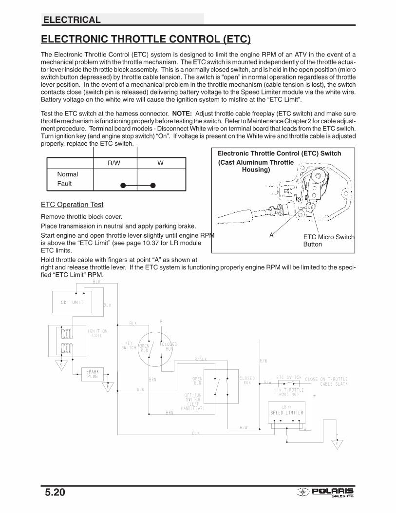
ELECTRICAL
5.20
ELECTRONIC THROTTLE CONTROL (ETC)The Electronic Throttle Control (ETC) system is designed to limit the engine RPM of an ATV in the event of amechanical problem with the throttle mechanism. The ETC switch is mounted independently of the throttle actua-tor lever inside the throttle block assembly. This is a normally closed switch, and is held in the open position (microswitch button depressed) by throttle cable tension. The switch is “open” in normal operation regardless of throttlelever position. In the event of a mechanical problem in the throttle mechanism (cable tension is lost), the switchcontacts close (switch pin is released) delivering battery voltage to the Speed Limiter module via the white wire.Battery voltage on the white wire will cause the ignition system to misfire at the “ETC Limit”.
Test the ETC switch at the harness connector. NOTE: Adjust throttle cable freeplay (ETC switch) and make surethrottle mechanism is functioning properly before testing the switch. Refer to Maintenance Chapter 2 for cable adjust-ment procedure. Terminal board models - Disconnect White wire on terminal board that leads from the ETC switch.Turn ignition key (and engine stop switch) “On”. If voltage is present on the White wire and throttle cable is adjustedproperly, replace the ETC switch.
ETC Operation Test
Remove throttle block cover.
Place transmission in neutral and apply parking brake.
Start engine and open throttle lever slightly until engine RPM is above the “ETC Limit” (see page 10.37 for LR moduleETC limits.
Hold throttle cable with fingers at point “A” as shown atright and release throttle lever. If the ETC system is functioning properly engine RPM will be limited to the speci-fied “ETC Limit” RPM.
R/W W
NormalFault � �
Electronic Throttle Control (ETC) Switch
ETC Micro SwitchButton
A
(Cast Aluminum ThrottleHousing)
ELECTRICAL
5.21
IGNITION SYSTEM TROUBLESHOOTINGNo Spark, Weak or Intermittent Spark
�Spark plug gap incorrect�Fouled spark plug
�Faulty spark plug cap or poor connection to high tension lead
�Related wiring loose, disconnected, shorted, or corroded
�Engine Stop switch or ignition switch faulty
�ETC switch misadjusted or faulty
�Terminal board or connections wet, corroded
�Poor ignition coil ground (e.g. coil mount loose or corroded)
�Faulty stator (measure resistance of all ignition related windings)
�Incorrect wiring (inspect color coding in connectors etc)
�Faulty ignition coil winding (measure resistance of primary and secondary)�Worn magneto (RH) end Crankshaft bearings
�Sheared flywheel key
�Flywheel loose or damaged
�Excessive crankshaft runout on magneto (RH) end - should not exceed .0024″�Faulty CDI module
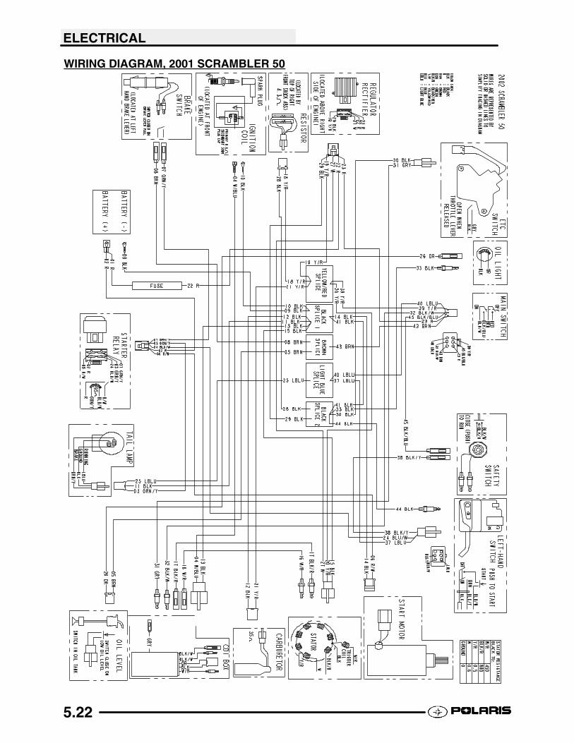
ELECTRICAL
5.22
WIRING DIAGRAM, 2001 SCRAMBLER 50
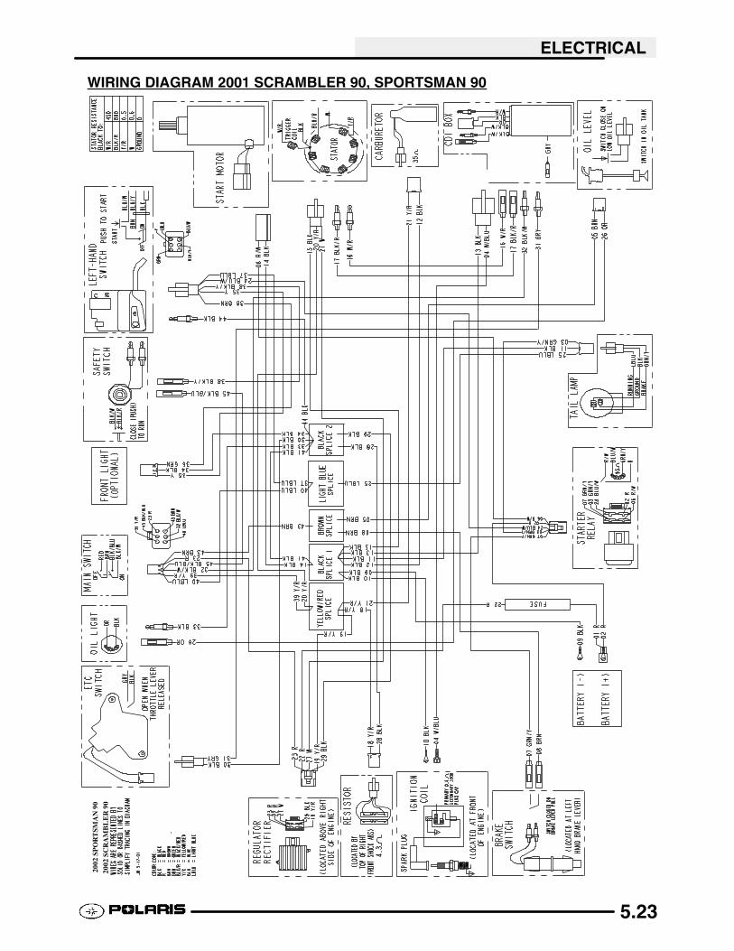
ELECTRICAL
5.23
WIRING DIAGRAM 2001 SCRAMBLER 90, SPORTSMAN 9020
02SP
OR
TSM
AN
9020
02SC
RA
MB
LE
R90