chapter 01 foundations (fnd) - maryland state … · chapter 01 - foundations. section 01 general...
TRANSCRIPT
OFFICE OF STRUCTURES STRUCTURAL DETAIL MANUAL
Chapter 01
FOUNDATIONS (FND)
OFFICE OF STRUCTURES STRUCTURAL DETAIL MANUAL
Chapter 01 - Foundations
SECTION 01
GENERAL (FND-GN)
DATE:
STATE HIGHWAY ADMINISTRATION
DEPARTMENT OF TRANSPORTATION
STATE OF MARYLAND
SHEET OF
APPROVAL
T. an
d B
. w
ing w
all tran
sver
se b
ars
Wing w
all longitudinal bars
Abutm
ent
longit
udin
al
bars
Transition axis
T. and B. abutment transverse bars
Rear face
of footing
concrete
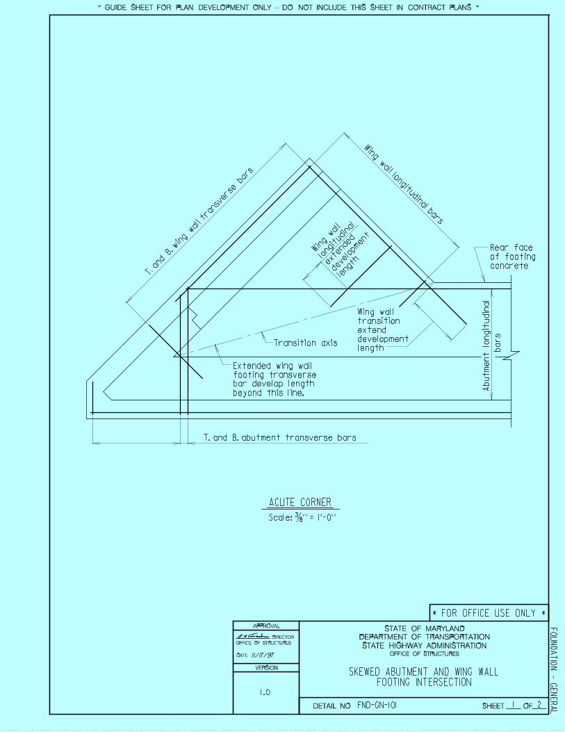
ACUTE CORNER
Scale: 3/8 ’’ = 1’-0’’
SKEWED ABUTMENT AND WING WALLFOOTING INTERSECTION
1 2
Wing wall
transition
extend
development
length
Extended wing wall
footing transverse
bar develop length
beyond this line.
Win
g w
all
longitudin
al
exte
nded
deve
lopm
ent
length
11/17/97 OFFICE OF STRUCTURES
DIRECTOR
OFFICE OF STRUCTURES
FND-GN-101
FO
UN
DA
TIO
N - G
EN
ER
AL
* GUIDE SHEET FOR PLAN DEVELOPMENT ONLY - DO NOT INCLUDE THIS SHEET IN CONTRACT PLANS *
* FOR OFFICE USE ONLY *
DETAIL NO.
VERSION
1.0
DATE:
STATE HIGHWAY ADMINISTRATION
DEPARTMENT OF TRANSPORTATION
STATE OF MARYLAND
SHEET OF
APPROVAL
Abutm
ent
longit
udin
al
bars
Transition axis
Rear face
of footing
concrete
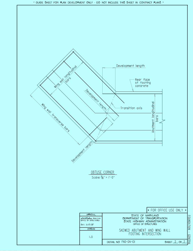
Scale: 3/8 ’’ = 1’-0’’
OBTUSE CORNER
SKEWED ABUTMENT AND WING WALLFOOTING INTERSECTION
2 2
Development length
Dev
elop
men
t leng
th
Dev
elopm
ent le
ngth
bar
s
Win
g w
all transv
erse bars
Win
g w
all lon
gitu
dina
l
11/17/97 OFFICE OF STRUCTURES
DIRECTOR
OFFICE OF STRUCTURES
* FOR OFFICE USE ONLY *
FO
UN
DA
TIO
N - G
EN
ER
AL
* GUIDE SHEET FOR PLAN DEVELOPMENT ONLY - DO NOT INCLUDE THIS SHEET IN CONTRACT PLANS *
FND-GN-101DETAIL NO.
VERSION
1.0
OFFICE OF STRUCTURES STRUCTURAL DETAIL MANUAL
Chapter 01 - Foundations
SECTION 02
PILE FOUNDATION (FND-PF)
1 1
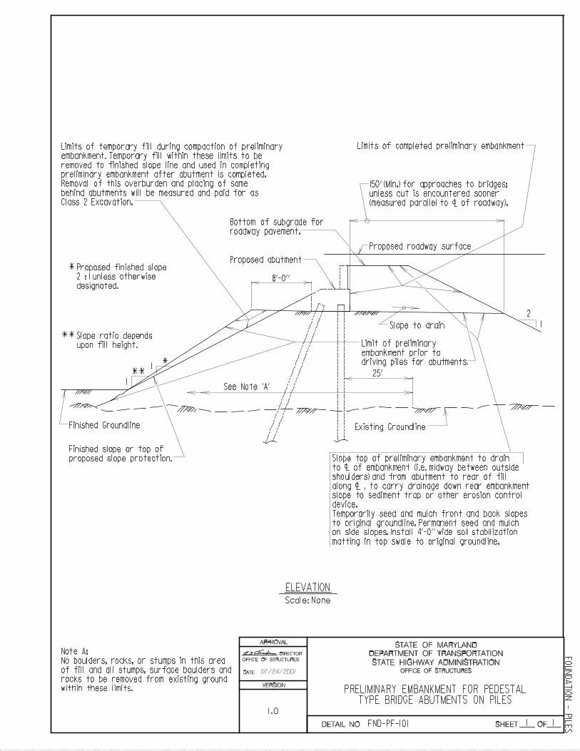
PRELIMINARY EMBANKMENT FOR PEDESTALTYPE BRIDGE ABUTMENTS ON PILES
Note A:
No boulders, rocks, or stumps in this area
of fill and all stumps, surface boulders and
rocks to be removed from existing ground
within these limits.
Proposed roadway surface
150’ (Min.) for approaches to bridges;
unless cut is encountered sooner
(measured parallel to of roadway).c
Limits of completed preliminary embankment
Slope to drain
Limit of preliminary
embankment prior to
driving piles for abutments.
25’
See Note ’A’
2
1
Slope top of preliminary embankment to drain
to of embankment (i.e. midway between outside
shoulders) and from abutment to rear of fill
along , to carry drainage down rear embankment
slope to sediment trap or other erosion control
device.
Temporarily seed and mulch front and back slopes
to original groundline. Permanent seed and mulch
c
c
Bottom of subgrade for
roadway pavement.
Proposed abutment
8’-0’’
1 *1
**
**
*Proposed finished slope
2 : 1 unless otherwise
designated.
Slope ratio depends
upon fill height.
Finished Groundline Existing Groundline
Finished slope or top of
proposed slope protection.
Limits of temporary fill during compaction of preliminary
embankment. Temporary fill within these limits to be
removed to finished slope line and used in completing
preliminary embankment after abutment is completed.
Removal of this overburden and placing of same
behind abutments will be measured and paid for as
Class 2 Excavation.
ELEVATION
Scale: None
DATE:
STATE HIGHWAY ADMINISTRATION
DEPARTMENT OF TRANSPORTATION
STATE OF MARYLAND
SHEET OF
APPROVAL
on side slopes. Install 4’-0’’ wide soil stabilization
matting in top swale to original groundline.
OFFICE OF STRUCTURES
DIRECTOR
OFFICE OF STRUCTURES
FND-PF-101
FO
UN
DA
TIO
N - P
ILE
SDETAIL NO.
VERSION
1.0
07/24/2001
1 1
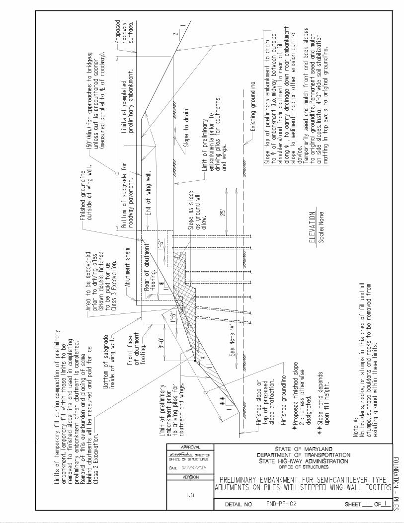
No
te A
:
PRELIMINARY EMBANKMENT FOR SEMI-CANTILEVER TYPEABUTMENTS ON PILES WITH STEPPED WING WALL FOOTERS
15
0’
(Min
.) f
or
ap
pro
ach
es
to b
rid
ges;
unle
ss c
ut
is e
ncounte
red s
ooner
(measu
red
para
llel
to
of
road
way
).c
Slo
pe t
o d
rain
25’
See N
ote
’A
’
2
1
Slo
pe t
op o
f pre
lim
inary
em
bankm
ent
to d
rain
to
of
em
ban
km
en
t (i
.e.
mid
way
betw
een
ou
tsid
e
should
ers
) and f
rom
abutm
ent
to r
ear
of
fill
alo
ng
,
to
carr
y d
rain
ag
e d
ow
n r
ear
em
ban
km
en
t
slo
pe t
o s
ed
imen
t tr
ap
or
oth
er
ero
sio
n c
on
tro
l
dev
ice.
Tem
po
rari
ly s
eed
an
d m
ulc
h f
ron
t an
d b
ack
slo
pes
to o
rig
inal
gro
un
dli
ne.
Perm
an
en
t se
ed
an
d m
ulc
h
c
c
Bott
om
of
subgra
de f
or
roadw
ay p
avem
ent.
8’-0
’’
1*
1**
**
Slo
pe r
ati
o d
ep
en
ds
upon f
ill
heig
ht.
Exis
ting g
roundli
ne
Lim
its o
f te
mpora
ry f
ill
duri
ng c
om
pacti
on o
f pre
lim
inary
em
bankm
ent.
Tem
pora
ry f
ill
wit
hin
these l
imit
s t
o b
e
rem
ov
ed
to
fin
ish
ed
slo
pe l
ine a
nd
used
in
co
mp
leti
ng
pre
lim
inary
em
bankm
ent
aft
er
abutm
ent
is c
om
ple
ted.
Rem
oval
of
this
overb
urd
en a
nd p
lacin
g o
f sam
e
behin
d a
butm
ents
wil
l b
e m
easure
d a
nd p
aid
for
as
Cla
ss 2
Excavati
on.
EL
EV
AT
ION
Scale
: N
one
No
bo
uld
ers
, ro
ck
s,
or
stu
mp
s i
n t
his
are
a o
f fi
ll
an
d a
ll
stu
mp
s,
su
rface b
ou
lders
an
d r
ock
s t
o b
e r
em
ov
ed
fro
m
exis
ting g
round w
ithin
these l
imit
s.
Fin
ished s
lope o
r
top o
f pro
posed
slo
pe p
rote
cti
on
.
Fin
ished g
roundli
ne
*Pro
po
sed
fin
ish
ed
slo
pe
2 :
1 u
nle
ss o
therw
ise
desi
gn
ate
d.
Lim
it o
f pre
lim
inary
em
bankm
ent
pri
or
to d
riv
ing
pil
es f
or
abutm
ent
and w
ings.
Fro
nt
face
of
abutm
ent
foo
tin
g.
Bott
om
of
subgra
de
insi
de o
f w
ing w
all
.
Slo
pe a
s s
teep
as g
round w
ill
allo
w.
L
imit
of
pre
lim
inary
em
bankm
ents
pri
or
to
dri
vin
g p
iles f
or
ab
utm
en
ts
and w
ings.
*1
R
ear
of
abutm
ent
fo
oti
ng
.
Ab
utm
en
t st
em
Are
a t
o b
e e
xcavate
d
pri
or
to d
riv
ing
pil
es
(sh
ow
n d
ou
ble
hatc
hed
to b
e p
aid
fo
r as
Cla
ss 3
Excavati
on.
Pro
pose
d
roadw
ay
surf
ace.
Lim
its
of
co
mp
lete
d
pre
lim
inary
em
ban
km
en
t.
DATE:
STATE HIGHWAY ADMINISTRATION
DEPARTMENT OF TRANSPORTATION
STATE OF MARYLAND
SHEET OF
APPROVAL
1’-6
’’
1’-6
’’
En
d o
f w
ing
wall
.
on
sid
e s
lop
es.
In
stall
4
’-0
’’ w
ide s
oil
sta
bil
izati
on
matt
ing
in
to
p s
wale
to
ori
gin
al
gro
un
dli
ne.
Fin
ished g
roundli
ne
outs
ide o
f w
ing w
all
.
OFFICE OF STRUCTURES
DIRECTOR
OFFICE OF STRUCTURES
FND-PF-102
FO
UN
DA
TIO
N - P
ILE
S
VERSION
DETAIL NO.
1.0
07/24/2001
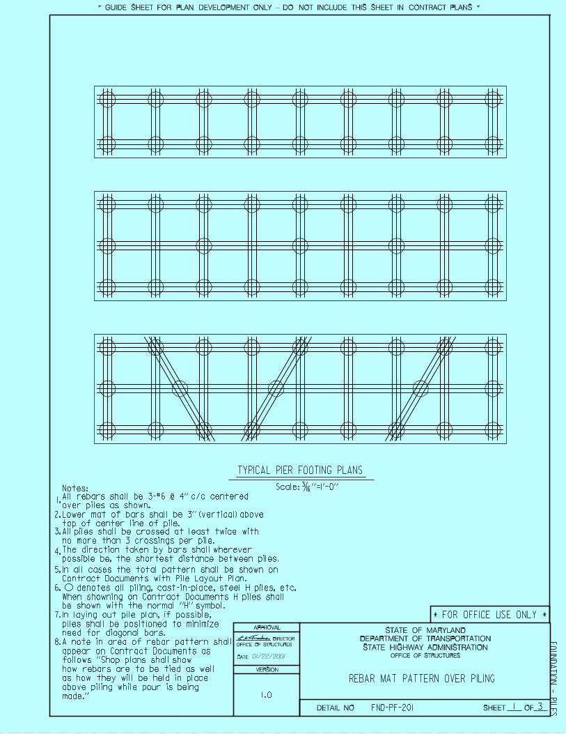
REBAR MAT PATTERN OVER PILING
3
TYPICAL PIER FOOTING PLANS
1
Scale: 3/16 ’’=1’-0’’
In laying out pile plan, if possible,
piles shall be positioned to minimize
need for diagonal bars.
A note in area of rebar pattern shall
appear on Contract Documents as
When showning on Contract Documents H piles shall
be shown with the normal ’’H’’ symbol.
follows ’’Shop plans shall show
how rebars are to be tied as well
as how they will be held in place
above piling while pour is being
made.’’
1.
2.
3.
4.
5.
6.
7.
8.
Notes:
DATE:
STATE HIGHWAY ADMINISTRATION
DEPARTMENT OF TRANSPORTATION
STATE OF MARYLAND
SHEET OF
APPROVAL
OFFICE OF STRUCTURES
DIRECTOR
OFFICE OF STRUCTURES
* FOR OFFICE USE ONLY *
FND-PF-201
FO
UN
DA
TIO
N - P
ILE
S* GUIDE SHEET FOR PLAN DEVELOPMENT ONLY - DO NOT INCLUDE THIS SHEET IN CONTRACT PLANS *
In all cases the total pattern shall be shown on
Contract Documents with Pile Layout Plan.
All rebars shall be 3-#6 @ 4’’ c/c centered
over piles as shown.
Lower mat of bars shall be 3’’ (vertical) above
top of center line of pile.
denotes all piling, cast-in-place, steel H piles, etc.
All piles shall be crossed at least twice with
no more than 3 crossings per pile.
The direction taken by bars shall wherever
possible be, the shortest distance between piles.
VERSION
DETAIL NO.
1.0
01/22/2001
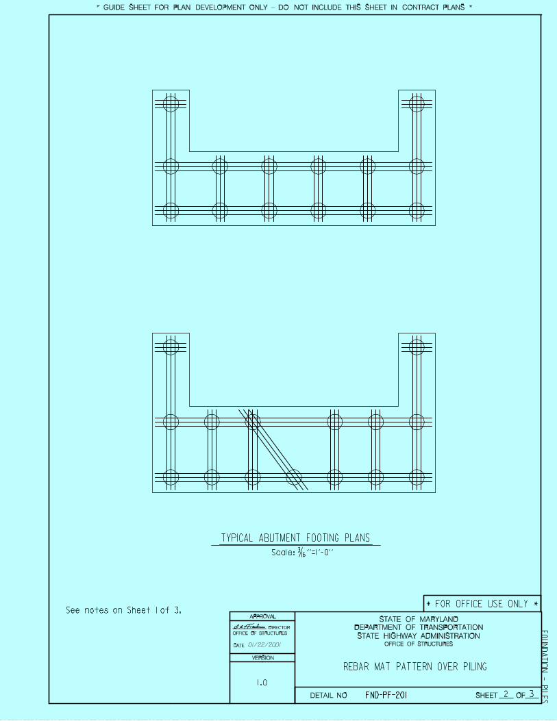
TYPICAL ABUTMENT FOOTING PLANS
REBAR MAT PATTERN OVER PILING
2 3
See notes on Sheet 1 of 3.
DATE:
STATE HIGHWAY ADMINISTRATION
DEPARTMENT OF TRANSPORTATION
STATE OF MARYLAND
SHEET OF
APPROVAL
Scale: 3/16 ’’=1’-0’’
OFFICE OF STRUCTURES
DIRECTOR
OFFICE OF STRUCTURES
* FOR OFFICE USE ONLY *
FND-PF-201
FO
UN
DA
TIO
N - P
ILE
S* GUIDE SHEET FOR PLAN DEVELOPMENT ONLY - DO NOT INCLUDE THIS SHEET IN CONTRACT PLANS *
VERSION
DETAIL NO.
01/22/2001
1.0
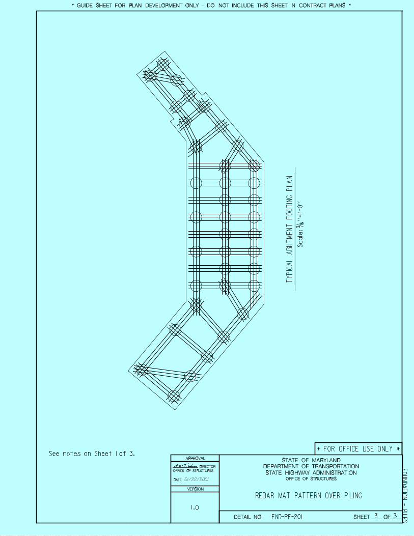
REBAR MAT PATTERN OVER PILING
3
See notes on Sheet 1 of 3.
3
TY
PIC
AL
AB
UT
ME
NT
FO
OT
ING
PL
AN
DATE:
STATE HIGHWAY ADMINISTRATION
DEPARTMENT OF TRANSPORTATION
STATE OF MARYLAND
SHEET OF
APPROVAL
Sca
le:
3/1
6 ’
’=1
’-0
’’
OFFICE OF STRUCTURES
DIRECTOR
OFFICE OF STRUCTURES
* FOR OFFICE USE ONLY *
FND-PF-201
FO
UN
DA
TIO
N - P
ILE
S* GUIDE SHEET FOR PLAN DEVELOPMENT ONLY - DO NOT INCLUDE THIS SHEET IN CONTRACT PLANS *
VERSION
DETAIL NO.
01/22/2001
1.0
1 1
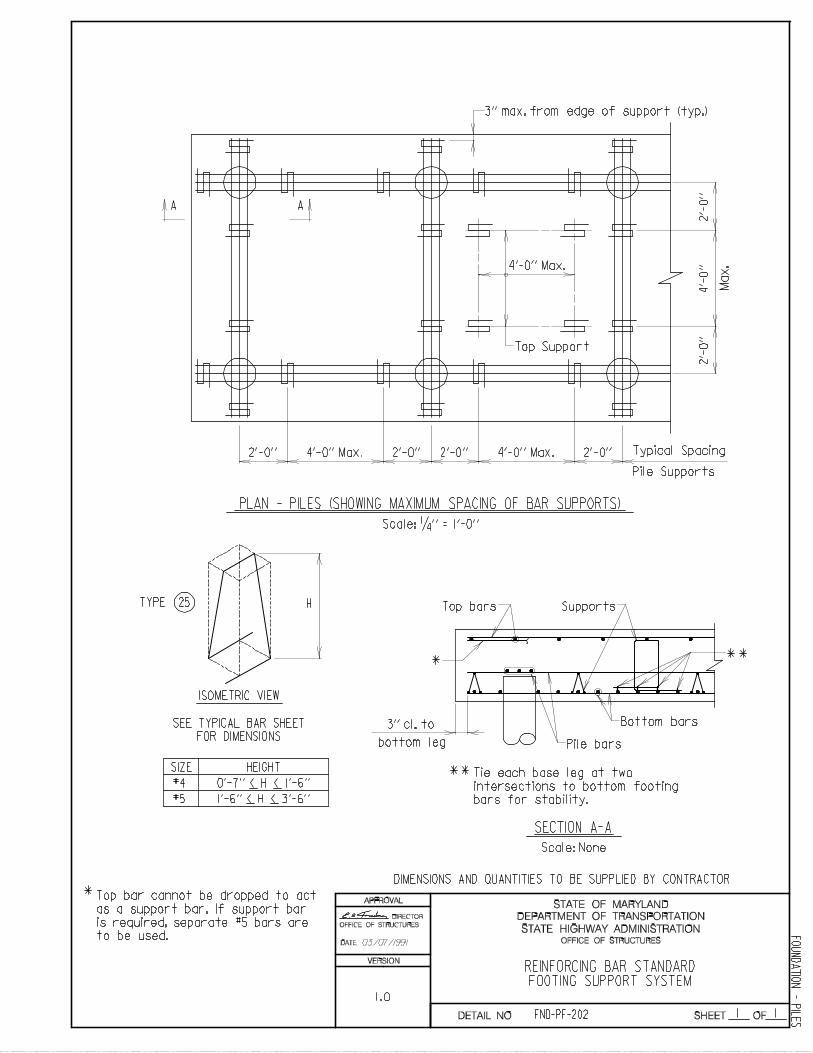
REINFORCING BAR STANDARDFOOTING SUPPORT SYSTEM
2’-0’’ 2’-0’’ 2’-0’’ 2’-0’’4’-0’’ Max. 4’-0’’ Max. Typical Spacing
Pile Supports
2’-
0’’
2’-
0’’
4’-
0’’4’-0’’ Max.
Top Support
A A
PLAN - PILES (SHOWING MAXIMUM SPACING OF BAR SUPPORTS)
Scale: 1/4 ’’ = 1’-0’’
HTYPE 25
ISOMETRIC VIEW
SEE TYPICAL BAR SHEET
FOR DIMENSIONS
#4 0’-7’’ < H < 1’-6’’
#5 1’-6’’ < H < 3’-6’’
SIZE HEIGHT
*Top bar cannot be dropped to act
as a support bar. If support bar
is required, separate #5 bars are
to be used.
* **
Top bars Supports
Bottom bars
Pile bars
3’’ cl. to
bottom leg
Tie each base leg at two
intersections to bottom footing
bars for stability.
**
SECTION A-A
Scale: None
DIMENSIONS AND QUANTITIES TO BE SUPPLIED BY CONTRACTOR
DATE:
STATE HIGHWAY ADMINISTRATION
DEPARTMENT OF TRANSPORTATION
STATE OF MARYLAND
SHEET OF
APPROVAL
OFFICE OF STRUCTURES
DIRECTOR
OFFICE OF STRUCTURES
FND-PF-202
FO
UN
DA
TIO
N - P
ILE
S
3’’ max. from edge of support (typ.)
Max
.
VERSION
DETAIL NO.
03/07/1991
1.0
1 1
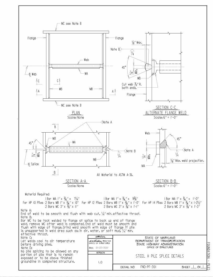
STEEL H PILE SPLICE DETAILS
Note A:
End of weld to be smooth and flush with web cut, 1/4 ’’ min. effective throat.
Note B:
Bar MC to be tack welded to flange at splice to back up end of flange
weld, remove MC after weld is completed. End of weld must be smooth and
flush with edge of flange. Grind weld smooth with edge of flange if pile
Note C:
Let welds cool to air temperature
before driving piles.
Note D:
is unsupported in weld area such as: in air, water, or soft mud, 1/4 ’’ min.
effective throat.
No pile splicing to be allowed on any
portion of pile that is to remain
1 Bar MA 1’’ x 3/16 ’’ x 7 1/4 ’’
2 Bars MB 1’’ x 3/16 ’’ x 10’’
2 Bars MC 3’’ x 3/8 ’’ x 11’’
1 Bar MA 1’’ x 3/16 ’’ x 9 3/8 ’’ 1 Bar MA 1’’ x 3/16 ’’ x 1’-0’’
2 Bars MB 1’’ x 3/16 ’’ x 1’-0’’
2 Bars MC 3’’ x 3/8 ’’ x 1’-1’’
2 Bars MB 1’’ x 3/16 ’’ x 1-2 1/2 ’’
2 Bars MC 3’’ x 3/8 ’’ x 1’-3’’
Material Required:
Web
45
1/4 ’
’
Min
.
MA
1/8 ’’ Max. weld projection.
1/4
Note A
B
B
Note A
MA
MB
MB
1/4
Note B
45
1/4 ’
’
Min
.
c Splice
SECTION A-A
Scale: None
SECTION B-B
Scale: 6’’ = 1’-0’’
All Material to ASTM A-36.
Scale: None Scale: 6’’ = 1’-0’’
PLAN
SECTION C-C
ALTERNATE FLANGE WELD
MC see Note B
Flange
Flange
Flange
Web
MAc Web
MB
CC
A AMB
MC see Note B
1/8 ’’ Max.
1/4 ’
’
Min
.
Note B
1/4
45
MB
Cut web 3/4 ’’ R.
both ends.
DATE:
STATE HIGHWAY ADMINISTRATION
DEPARTMENT OF TRANSPORTATION
STATE OF MARYLAND
SHEET OF
APPROVAL
For HP 10 Piles For HP 12 Piles For HP 14 Piles
exposed or to be above finished
groundline in completed structure.
OFFICE OF STRUCTURES
DIRECTOR
OFFICE OF STRUCTURES
FND-PF-301
FO
UN
DA
TIO
N - P
ILE
S
VERSION
DETAIL NO.
1.0
01/22/2001
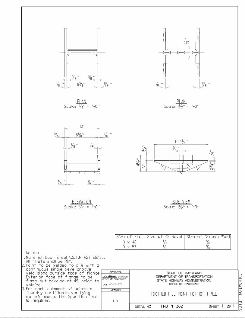
1
5/16 ’’ 5/16 ’’
5/16 ’’ 5/16 ’’
1/16 ’’ 1/16 ’’
PLAN
ELEVATION SIDE VIEW
1
Point to be welded to pile with a2.
1.
3.
continuous single bevel groove
weld along outside face of flange.
Exterior face of flange to be
flame cut beveled at 45, prior to
welding.
For each shipment of points a
foundry certificate verifying
material meets the Specifications
is required.
Size of Pile Size of 45 Bevel Size of Groove Weld
5/16
8 5/8 ’’
8 5/8 ’’
10’’
11/16 ’’ 11/16 ’’
11/16 ’’ 11/16 ’’
1’-2 7/8 ’’
1/4
’’
PLAN
11/16 ’’ 11/16 ’’
3/4 ’’
3/4 ’’
1 1/
2 ’’
3’’4
1/2
’’
TOOTHED PILE POINT FOR 10’’ H PILE
10 x 42
10 x 57
1/4
1/4
5/16
1 3/
8 ’’
Material: Cast Steel A.S.T.M. A27 65/35.
Scale: 1 1/2 ’’ = 1’-0’’ Scale: 1 1/2 ’’ = 1’-0’’
Scale: 1 1/2 ’’ = 1’-0’’ Scale: 1 1/2 ’’ = 1’-0’’
2 3/
4 ’’
DATE:
STATE HIGHWAY ADMINISTRATION
DEPARTMENT OF TRANSPORTATION
STATE OF MARYLAND
SHEET OF
APPROVAL
OFFICE OF STRUCTURES
DIRECTOR
OFFICE OF STRUCTURES
FND-PF-302
FO
UN
DA
TIO
N - P
ILE
S
All fillets shall be 3/8 ’’.
Notes:
VERSION
DETAIL NO.
12/13/1979
1.0

1
5/16 ’’ 5/16 ’’
5/16 ’’ 5/16 ’’
1/16 ’’ 1/16 ’’
PLAN
ELEVATION SIDE VIEW
1
Point to be welded to pile with a2.
1.
3.
continuous single bevel groove
weld along outside face of flange.
Exterior face of flange to be
flame cut beveled at 45, prior to
welding.
For each shipment of points a
foundry certificate verifying
material meets the Specifications
is required.
Size of Pile Size of 45 Bevel Size of Groove Weld
5/16
11/16 ’’ 11/16 ’’
11/16 ’’ 11/16 ’’
1’-2 7/8 ’’
1/4
’’
PLAN
11/16 ’’ 11/16 ’’
1 1/
2 ’’
4 1/
2 ’’
1/4 5/16 12 x 53
12 x 74
TOOTHED PILE POINT FOR 12’’ H PILE
5/16
1 1/
2 ’’
1’-0 1/8 ’’
10 23/32 ’’
3 1/
2 ’’
23/32
23/32
’’
’’
Scale: 1 1/2 ’’ = 1’-0’’ Scale: 1 1/2 ’’ = 1’-0’’
Scale: 1 1/2 ’’ = 1’-0’’Scale: 1 1/2 ’’ = 1’-0’’
3 1/
4 ’’
DATE:
STATE HIGHWAY ADMINISTRATION
DEPARTMENT OF TRANSPORTATION
STATE OF MARYLAND
SHEET OF
APPROVAL
10 23/32 ’’
Material: Cast Steel A27 65/35.
OFFICE OF STRUCTURES
DIRECTOR
OFFICE OF STRUCUTRES
FND-PF-303
FO
UN
DA
TIO
N - P
ILE
S
All fillets shall be 3/8 ’’.
Notes:
VERSION
DETAIL NO.
04/28/1994
1.0
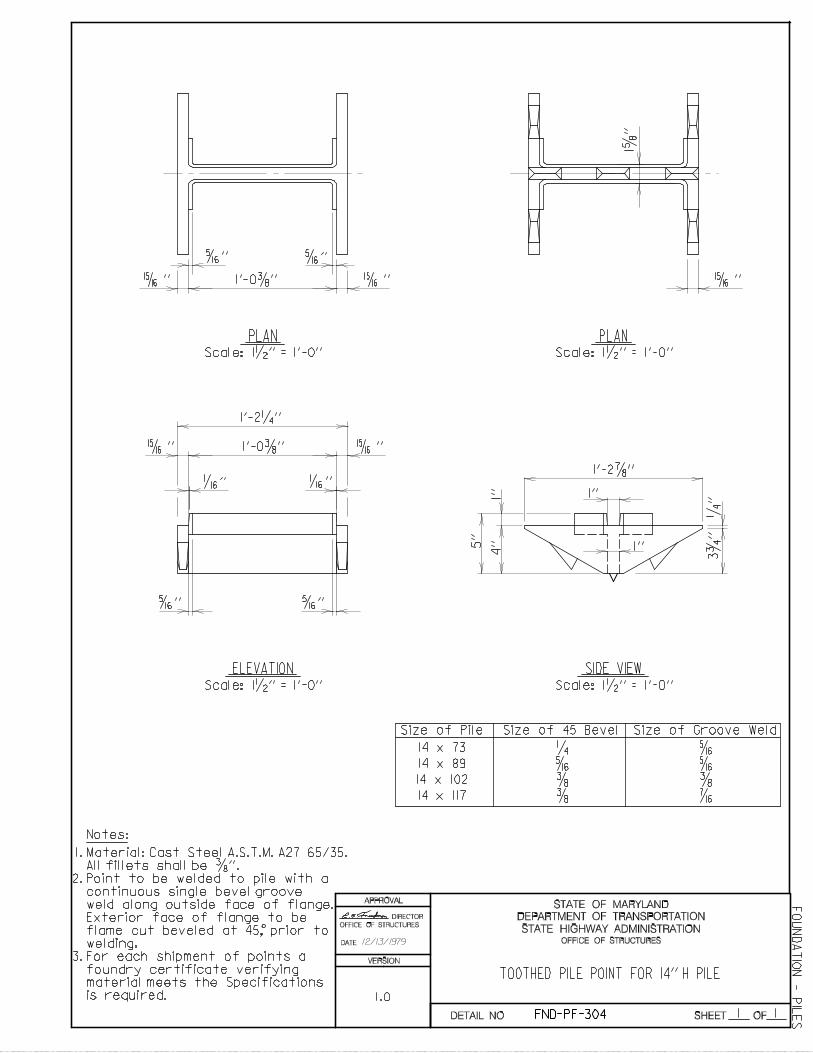
1
15/16 ’’ 15/16 ’’1’-0 3/8 ’’
5/16 ’’ 5/16 ’’
5/16 ’’ 5/16 ’’
1/16 ’’ 1/16 ’’
15/16 ’’ 1’-0 3/8 ’’ 15/16 ’’
1’-2 1/4 ’’
1’’
1’-2 7/8 ’’
1’’
1/4
’’
PLAN
ELEVATION SIDE VIEW
1
Point to be welded to pile with a2.
1.
3.
continuous single bevel groove
weld along outside face of flange.
Exterior face of flange to be
flame cut beveled at 45, prior to
welding.
For each shipment of points a
foundry certificate verifying
material meets the Specifications
is required.
Size of Pile Size of 45 Bevel Size of Groove Weld
14 x 73
14 x 89
14 x 102
14 x 117
5/16
3/8
3/8
3/8
5/16
5/16
7/16
1/4
3 3/
4 ’’
1’’
4’’5
’’
TOOTHED PILE POINT FOR 14’’ H PILE
15/16 ’’
PLAN
1 5/
8 ’’
Material: Cast Steel A.S.T.M. A27 65/35.
Scale: 1 1/2 ’’ = 1’-0’’ Scale: 1 1/2 ’’ = 1’-0’’
Scale: 1 1/2 ’’ = 1’-0’’ Scale: 1 1/2 ’’ = 1’-0’’
DATE:
STATE HIGHWAY ADMINISTRATION
DEPARTMENT OF TRANSPORTATION
STATE OF MARYLAND
SHEET OF
APPROVAL
OFFICE OF STRUCTURES
DIRECTOR
OFFICE OF STRUCTURES
FND-PF-304
FO
UN
DA
TIO
N - P
ILE
S
All fillets shall be 3/8 ’’.
Notes:
VERSION
DETAIL NO.
12/13/1979
1.0
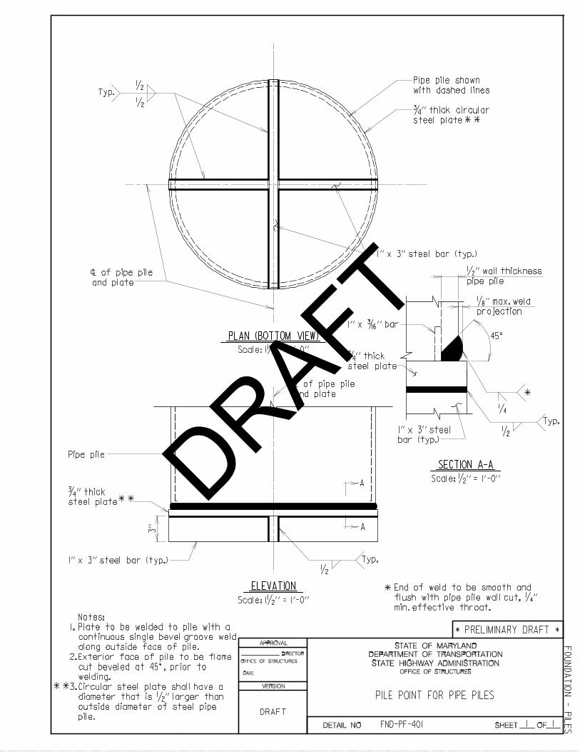
*
1.
2.
1 1
Notes:
Scale: 1 1/2 ’’ = 1’-0’’
Typ.
1/2
1/2
45^
1/4
1/8 ’’ max. weld
projection
1’’ x 3’’ steel bar (typ.)
1’’ x 3’’ steel bar (typ.)
3/4 ’’ thick
steel plate
1’’ x 3/16 ’’ bar
L of pipe pile
and plate
c
A
A
SECTION A-A
Scale: 1/2 ’’ = 1’-0’’
Scale: 1 1/2 ’’ = 1’-0’’
ELEVATION
*
End of weld to be smooth and
flush with pipe pile wall cut, 1/4 ’’
min. effective throat.
Typ.
1/2
L of pipe pile
and plate
c
Typ.
1/2
1’’ x 3’’ steel
bar (typ.)
PILE POINT FOR PIPE PILES
Plate to be welded to pile with a
continuous single bevel groove weld
along outside face of pile.
Exterior face of pile to be flame
cut beveled at 45^, prior to
welding.
Circular steel plate shall have a
diameter that is 1/2 ’’ larger than
outside diameter of steel pipe
pile.
3.**
3/4 ’’ thick
steel plate **
Pipe pile
1/2 ’’ wall thickness
pipe pile
PLAN (BOTTOM VIEW)
**
Pipe pile shown
with dashed lines
3/4 ’’ thick circular
steel plate
FND-PF-401
FO
UN
DA
TIO
N - P
ILE
S
* PRELIMINARY DRAFT *
DATE:
STATE HIGHWAY ADMINISTRATION
DEPARTMENT OF TRANSPORTATION
STATE OF MARYLAND
SHEET OF
APPROVAL
VERSION
DETAIL NO.
OFFICE OF STRUCTURES
OFFICE OF STRUCTURES
DIRECTOR
DRAFT
DRAFT
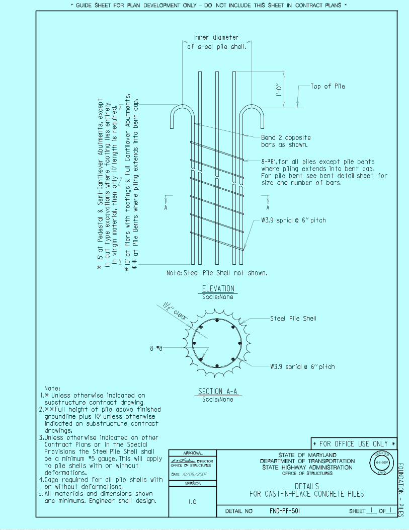
at
Pil
e B
en
ts w
here p
ilin
g e
xte
nd
s i
nto
ben
t cap
.
Inner diameter
of steel pile shell.
1’-
0’’ Top of Pile
Bend 2 opposite
bars as shown.
8-#8’,for all piles except pile bents
where piling extends into bent cap.
For pile bent see bent detail sheet for
size and number of bars.
Note: Steel Pile Shell not shown.
AA
Steel Pile Shell
8-#8
1 1/2 ’’ clear
1.
2.
3.
4.
DETAILSFOR CAST-IN-PLACE CONCRETE PILES
SECTION A-A
ELEVATION
1 1
Scale:None
Scale:None
DATE:
STATE HIGHWAY ADMINISTRATION
DEPARTMENT OF TRANSPORTATION
STATE OF MARYLAND
SHEET OF
APPROVAL
* **
*
*
**
1
5’ a
t P
edesta
l &
Sem
i-C
anti
lever A
butm
ents
, except
in c
ut
type e
xcavati
ons w
here f
oo
tin
g l
ies e
nti
rely
in v
irgin
mate
ria
l, t
hen o
nly
10’ l
ength
is r
equir
ed.
1
0’ a
t P
iers w
ith
fo
oti
ng
s &
Fu
ll
Can
tile
ver A
bu
tmen
ts.
W3.9 sprial @ 6’’ pitch
W3.9 sprial @ 6’’ pitch
Cage required for all pile shells with
or without deformations.
All materials and dimensions shown
are minimums. Engineer shall design.
5.
10-9-2007
L D
VERIFIED
Unless otherwise indicated on other
Contract Plans or in the Special
Provisions the Steel Pile Shell shall
be a minimum #5 gauge. This will apply
to pile shells with or without
deformations.
Note:
Unless otherwise indicated on
substructure contract drawing.
Full height of pile above finished
groundline plus 10’ unless otherwise
indicated on substructure contract
drawings.
RFOFFICE OF STRUCTURES
DIRECTOR
OFFICE OF STRUCTURES
* GUIDE SHEET FOR PLAN DEVELOPMENT ONLY - DO NOT INCLUDE THIS SHEET IN CONTRACT PLANS *
* FOR OFFICE USE ONLY *
FND-PF-501
FO
UN
DA
TIO
N - P
ILE
S
VERSION
DETAIL NO.
10/09/2007
1.0
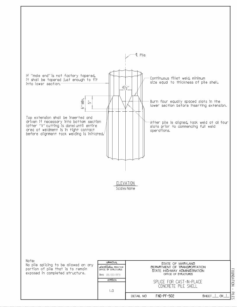
SPLICE FOR CAST-IN-PLACECONCRETE PILE SHELL
Note:
No pile splicing to be allowed on any
portion of pile that is to remain
exposed in completed structure.
Pilec
6’’
Min
.
4 1/2 ’’
Continuous fillet weld, minimum
size equal to thickness of pile shell.
Burn four equally spaced slots in the
lower section before inserting extension.
After pile is aligned, tack weld at all four
slots prior to commencing full weld
operations.
Top extension shall be inserted and
driven if necessary into bottom section
area of weldment is in tight contact
before alignment tack welding is initiated.
it shall be tapered just enough to fit
into lower section.
1 1
ELEVATION
Scale: None
DATE:
STATE HIGHWAY ADMINISTRATION
DEPARTMENT OF TRANSPORTATION
STATE OF MARYLAND
SHEET OF
APPROVAL
5’’
(after ’’V’’ cutting is done) until entire
If ’’male end’’ is not factory tapered,
OFFICE OF STRUCTURES
DIRECTOR
OFFICE OF STRUCTURES
FND-PF-502
FO
UN
DA
TIO
N - P
ILE
S
VERSION
DETAIL NO.
06/20/1975
1.0
1 1
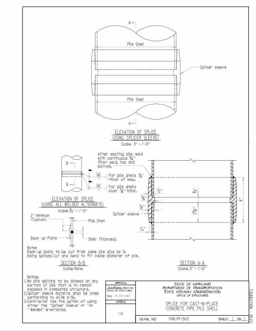
SPLICE FOR CAST-IN-PLACECONCRETE PIPE PILE SHELL
No pile splicing to be allowed on any
portion of pile that is to remain
exposed in completed structure.
Splicer sleeve material shall be steel
Contractor has the option of using
Notes:
1.
2.
3.
ELEVATION OF SPLICE
(USING ALL WELDED ALTERNATE)
Scale: 3/4 ’’ = 1’-0’’
B
B
M For pile shells 3/8 ’’
thick of less.
M For pile shells
over 3/8 ’’ thick.
ELEVATION OF SPLICE
(USING SPLICER SLEEVE)
Scale: 3’’ = 1’-0’’
A
A
After seating pile, weld
with continuous 5/16 ’’
fillet weld, top and
bottom.
Splicer sleeve2’’ minimum
(Typical).
Back up Plate
Pile Shell
Shell Thickness
Note:
Back-up plate to be cut from same pile size as is
being spliced. Cut and bend to fit inside diameter of pile.
SECTION B-B
Scale: None
6’’
3/4 ’
’2
5/8
’’
1/4 ’’
7/8 ’’
3/8 ’’
1/2 ’’
SECTION A-A
Scale: 3’’ = 1’-0’’
Pile Shell
Pile Shell
Splicer sleeve
DATE:
STATE HIGHWAY ADMINISTRATION
DEPARTMENT OF TRANSPORTATION
STATE OF MARYLAND
SHEET OF
APPROVAL
conforming to ASTM A-36.
either the ’’Splicer Sleeve’’ or ’’All
’’ Welded’’ alternates.
OFFICE OF STRUCTURES
DIRECTOR
OFFICE OF STRUCTURES
FND-PF-503
FO
UN
DA
TIO
N - P
ILE
S
VERSION
DETAIL NO.
01/22/2001
1.0
1 1
DATE:
STATE HIGHWAY ADMINISTRATION
DEPARTMENT OF TRANSPORTATION
STATE OF MARYLAND
SHEET OF
APPROVAL
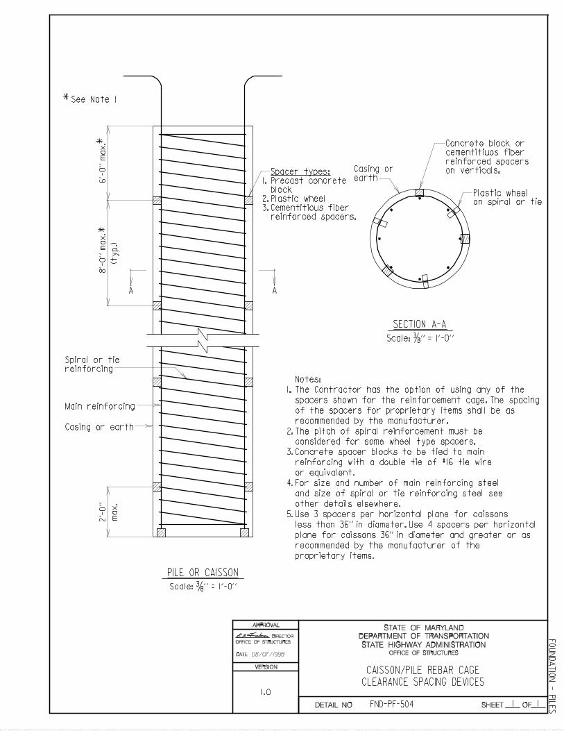
CAISSON/PILE REBAR CAGE
CLEARANCE SPACING DEVICES
6’-
0’’
max.
8’-
0’’
max
.
(ty
p.)
A A
Spiral or tie
reinforcing
Main reinforcing
Casing or earth
2’-
0’’
max.
SECTION A-A
PILE OR CAISSON
Scale: 3/8 ’’ = 1’-0’’
Scale: 3/8 ’’ = 1’-0’’
1.
2.
Casing or
earth
Notes:
The pitch of spiral reinforcement must be
considered for some wheel type spacers.
Concrete spacer blocks to be tied to main
reinforcing with a double tie of #16 tie wire
or equivalent.
For size and number of main reinforcing steel
and size of spiral or tie reinforcing steel see
other details elsewhere.
Use 3 spacers per horizontal plane for caissons
3.
4.
5.
1.
2.
3.
Concrete block or
cementitiuos fiber
reinforced spacers
on verticals.
Plastic wheel
on spiral or tie
recommended by the manufacturer of the
proprietary items.
**
*See Note 1
Spacer types:
Precast concrete
block
Plastic wheel
Cementitious fiber
reinforced spacers.
spacers shown for the reinforcement cage. The spacing
The Contractor has the option of using any of the
recommended by the manufacturer.
of the spacers for proprietary items shall be as
less than 36’’ in diameter. Use 4 spacers per horizontal
plane for caissons 36’’ in diameter and greater or as
OFFICE OF STRUCTURES
DIRECTOR
OFFICE OF STRUCTURES
FND-PF-504
FO
UN
DA
TIO
N - P
ILE
S
VERSION
DETAIL NO.
08/07/1998
1.0
OFFICE OF STRUCTURES STRUCTURAL DETAIL MANUAL
Chapter 01 - Foundations
SECTION 03
SLOPE PROTECTION
(FND-SP)
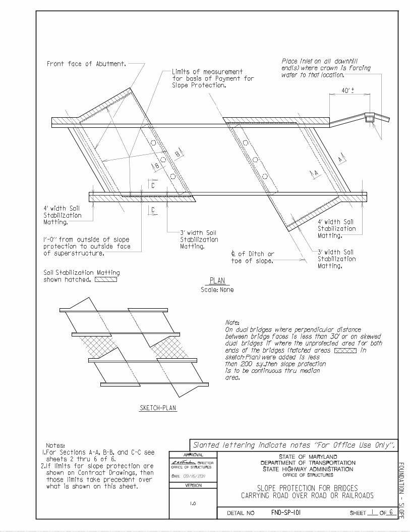
Front face of Abutment.
c
C
C
B
BA
A
PLAN
Scale: None
+-
Note:
SKETCH-PLAN
Place inlet on all downhill
end(s) where crown is forcing
water to that location.Limits of measurement
for basis of Payment for
Slope Protection.
1’-0’’ from outside of slope
protection to outside face
of superstructure. of Ditch or
toe of slope.
1
SLOPE PROTECTION FOR BRIDGESCARRYING ROAD OVER ROAD OR RAILROADS
Soil Stabilization Matting
shown hatched.
4’ width Soil
Stabilization
Matting.
3’ width Soil
Stabilization
Matting.3’ width Soil
Stabilization
Matting.
4’ width Soil
Stabilization
Matting.
On dual bridges where perpendicular distance
between bridge faces is less than 30’ or on skewed
than 200 s.y.,then slope protection
is to be continuous thru median
area.
dual bridges if where the unprotected area for both
ends of the bridges (hatched areas in
6
sketch-Plan) were added is less
For Sections A-A, B-B, and C-C see
sheets 2 thru 6 of 6.
If limits for slope protection are
shown on Contract Drawings, then
what is shown on this sheet.
those limits take precedent over
Notes:
1.
2.
DATE:
STATE HIGHWAY ADMINISTRATION
DEPARTMENT OF TRANSPORTATION
STATE OF MARYLAND
SHEET OF
APPROVAL
40’
OFFICE OF STRUCTURES
DIRECTOR
OFFICE OF STRUCTURES
FND-SP-101
FO
UN
DA
TIO
N - S
LO
PE
VERSION
1.0
DETAIL NO.
09/16/2011
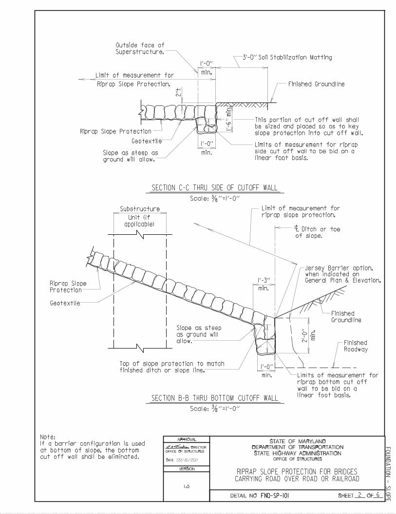
SECTION C-C THRU SIDE OF CUTOFF WALL
SECTION B-B THRU BOTTOM CUTOFF WALL
1’-0’’
min.
1’-0’’
min.
+ -
Limit of measurement for
Riprap Slope Protection.
be sized and placed so as to key
slope protection into cut off wall.
Limits of measurement for riprap
side cut off wall to be bid on a
linear foot basis.Slope as steep as
ground will allow.
Outside face of
Superstructure.
1’-0’’
min.
2’-
0’’
min
.
1’-3’’
min.
c
Substructure
Unit (if
applicable)
Limit of measurement for
riprap slope protection.
Ditch or toe
riprap bottom cut off
wall to be bid on a
linear foot basis.
Slope as steep
as ground will
allow.
Top of slope protection to match
finished ditch or slope line.
Riprap Slope
RIPRAP SLOPE PROTECTION FOR BRIDGESCARRYING ROAD OVER ROAD OR RAILROAD
3/8
This portion of cut off wall shall
Limits of measurement for
2 6
of slope.
3/8
Finished
Roadway
Jersey Barrier option,
when indicated on
General Plan & Elevation.
DATE:
STATE HIGHWAY ADMINISTRATION
DEPARTMENT OF TRANSPORTATION
STATE OF MARYLAND
NO. SHEET OF
APPROVAL
Riprap Slope Protection
Geotextile
Protection
Geotextile
Finished Groundline
Finished
Groundline
Note:
If a barrier configuration is used
at bottom of slope, the bottom
cut off wall shall be eliminated.
1’-
6’’
min
.
2’’
3’-0’’ Soil Stabilization Matting
Scale: ’’=1’-0’’
Scale: ’’=1’-0’’
OFFICE OF STRUCTURES
DIRECTOR
OFFICE OF STRUCTURES
FND-SP-101
FO
UN
DA
TIO
N - S
LO
PE
VERSION
1.0
DETAIL
09/16/2011
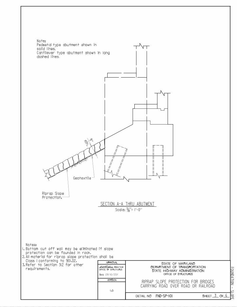
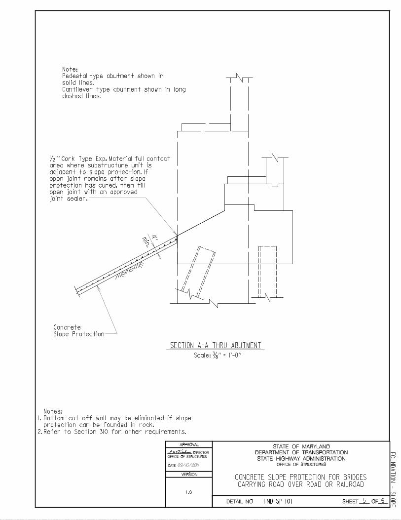
Notes:
Bottom cut off wall may be eliminated if slope
protection can be founded in rock.
1.
2.
3.
SECTION A-A THRU ABUTMENT
Riprap Slope
Protection.
min.
’’
RIPRAP SLOPE PROTECTION FOR BRIDGESCARRYING ROAD OVER ROAD OR RAILROAD
3/8
3 6
Note:
solid lines.
dashed lines.
Pedestal type abutment shown in
Cantilever type abutment shown in long
DATE:
STATE HIGHWAY ADMINISTRATION
DEPARTMENT OF TRANSPORTATION
STATE OF MARYLAND
SHEET OF
APPROVAL
All material for riprap slope protection shall be
Class 1 conforming to 901.02.
Geotextile
9’’
Scale: = 1’-0’’
OFFICE OF STRUCTURES
DIRECTOR
OFFICE OF STRUCTURES
Refer to Section 312 for other
requirements.
FND-SP-101
FO
UN
DA
TIO
N - S
LO
PE
1.0
VERSION
DETAIL NO.
09/16/2011
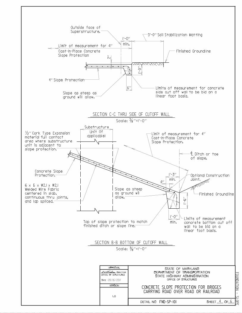
SECTION C-C THRU SIDE OF CUTOFF WALL
1’-0’’
min.
side cut off wall to be bid on a
linear foot basis.Slope as steep as
ground will allow.
Outside face of
Superstructure.
1’-3’’
min.
c
Substructure
Unit (if
applicable)
Ditch or toe
of slope.
Limits of measurement
wall to be bid on a
linear foot basis.
Top of slope protection to match
finished ditch or slope line.
Protection.
CONCRETE SLOPE PROTECTION FOR BRIDGESCARRYING ROAD OVER ROAD OR RAILROAD
3/8
Limit of measurement for 4’’
Cast-In-Place Concrete
Slope Protection
4’’ Slope Protection
Limits of measurement for concrete
concrete bottom cut off
Concrete Slope
1’-
6’’
6 x 6 x W2.1 x W2.1
Welded Wire Fabric
centered in slab,
continuous thru joints,
and lap spliced.
Limit of measurement for 4’’
Cast-In-Place Concrete
Slope Protection.
1/2
SECTION B-B BOTTOM OF CUTOFF WALL
Optional Construction
Joint.
4 6
’’ Cork Type Expansion
material full contact
area where substructure
unit is adjacent to
slope protection.
Slope as steep
as ground wil
allow.
1’-0’’
min.
3/8
DATE:
STATE HIGHWAY ADMINISTRATION
DEPARTMENT OF TRANSPORTATION
STATE OF MARYLAND
SHEET OF
APPROVAL
Finished Groundline
Finished Groundline
2’’
1’-
0’’
6’’
3’-0’’ Soil Stabilization Matting
4’’
Scale: ’’=1’-0’’
Scale: ’’=1’-0’’
OFFICE OF STRUCTURES
DIRECTOR
OFFICE OF STRUCTURES
FND-SP-101
FO
UN
DA
TIO
N - S
LO
PE
1.0
VERSION
DETAIL NO.
09/16/2011
1.
2.
SECTION A-A THRU ABUTMENT
min.
CONCRETE SLOPE PROTECTION FOR BRIDGESCARRYING ROAD OVER ROAD OR RAILROAD
Slope Protection
Notes:
Bottom cut off wall may be eliminated if slope
protection can be founded in rock.
area where substructure unit is
adjacent to slope protection. If
open joint remains after slope
protection has cured, then fill
joint sealer.
1/2
5 6
Note:
solid lines.
dashed lines.
Pedestal type abutment shown in
Cantilever type abutment shown in long
Concrete
DATE:
STATE HIGHWAY ADMINISTRATION
DEPARTMENT OF TRANSPORTATION
STATE OF MARYLAND
SHEET OF
APPROVAL
4’’
’’ Cork Type Exp. Material full contact
open joint with an approved
Scale: 3/8 ’’ = 1’-0’’
Refer to Section 310 for other requirements.
OFFICE OF STRUCTURES
DIRECTOR
OFFICE OF STRUCTURES
FND-SP-101
FO
UN
DA
TIO
N - S
LO
PE
1.0
VERSION
DETAIL NO.
09/16/2011
6 6
DATE:
STATE HIGHWAY ADMINISTRATION
DEPARTMENT OF TRANSPORTATION
STATE OF MARYLAND
SHEET OF
APPROVAL
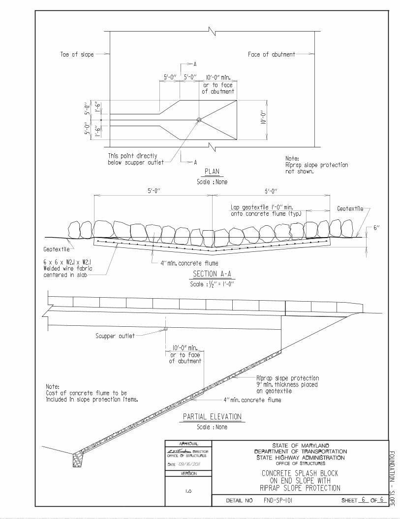
Scale : None
PARTIAL ELEVATION
CONCRETE SPLASH BLOCKON END SLOPE WITH
RIPRAP SLOPE PROTECTION
10’-0’’ min.
Scupper outlet
A
A
5’-0’’ 5’-0’’
6’’
5’-0
’’5’
-0’’
10’-
0’’
or to face
of abutment
This point directly
below scupper outlet
Face of abutment
SECTION A-A
Scale : 1/2 ’’ = 1’-0’’
Scale : None
PLAN
Note:
Riprap slope protection
not shown.
Toe of slope
or to face
of abutment
10’-0’’ min.
Geotextile
6 x 6 x W2.1 x W2.1
Welded wire fabric
centered in slab
4’’ min. concrete flume
4’’ min. concrete flume
Riprap slope protection
9’’ min. thickness placed
on geotextileNote:
Cost of concrete flume to be
included in slope protection items.
Lap geotextile 1’-0’’ min.
onto concrete flume (typ.)Geotextile
5’-0’’5’-0’’
1’-6
’’1’
-6’’
OFFICE OF STRUCTURES
DIRECTOR
OFFICE OF STRUCTURES
FND-SP-101
FO
UN
DA
TIO
N - S
LO
PE
1.0
VERSION
DETAIL NO.
09/16/2011
1 6
DATE:
STATE HIGHWAY ADMINISTRATION
DEPARTMENT OF TRANSPORTATION
STATE OF MARYLAND
SHEET OF
APPROVAL
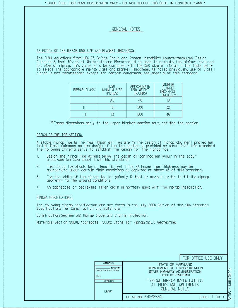
GENERAL NOTES
SELECTION OF THE RIPRAP D50 SIZE AND BLANKET THICKNESS:
The FHWA equations from HEC-23, Bridge Scour and Stream Instability Countermeasures (Design
Guideline 8, Rock Riprap at Abutments and Piers) should be used to compute the minimum required
D50 size of riprap. This value is to be compared with the D50 size of riprap in the table below
to select the appropriate riprap Class and blanket thickness. As noted previously, use of Class 1
riprap is not recommended except for certain conditions, see sheet 5 of this standard.
RIPRAP CLASSD50
MINIMUM SIZE(INCHES)
APPROXIMATED50 WEIGHT
(POUNDS) *
*These dimensions apply to the upper blanket section only, not the toe section.
MINIMUMBLANKET
THICKNESS (INCHES)
I 9.5 40 19
I I 16 200 32
I I I 23 600 46
DESIGN OF THE TOE SECTION:
A stable riprap toe is the most important feature in the design of riprap abutment protectioninstallations. Guidance on the design of the toe section is provided on sheet 2 of this standard
1.
2.
The following criteria serve to establish the design for the riprap toe: Design the riprap toe extend below the depth of contraction scour in the scour cross-section (see sheet 2 of this standard). The riprap toe should be at least 6 feet thick. (A lesser toe thickness may be
3.
4.
appropriate under certain field conditions as depicted on sheet 45 of this standard. The top width of the riprap toe is typically 12 feet or more in order to fit the riprap geometry to the ground conditions. An aggregate or geotextile filter cloth is normally used with the riprap installation.
RIPRAP SPECIFICATIONS:
TYPICAL RIPRAP INSTALLATIONSAT PIERS AND ABUTMENTS
GENERAL NOTES
* GUIDE SHEET FOR PLAN DEVELOPMENT ONLY - DO NOT INCLUDE THIS SHEET IN CONTRACT PLANS *
FO
UN
DA
TIO
N - S
OL
PEFND-SP-201
The following riprap specification are set forth in the July 2008 Edition of the SHA StandardSpecifications for Construction and Materials: Construction: Section 312, Riprap Slope and Channel Protection. Materials: Section 901.01, Aggregate ; 901.02 Stone for Riprap; 921.09 Geotextile.
DETAIL NO.
VERSION
FOR OFFICE USE ONLY
DRAFT
OFFICE OF STRUCTURES
DIRECTOR
OFFICE OF STRUCTURES
6
DATE:
STATE HIGHWAY ADMINISTRATION
DEPARTMENT OF TRANSPORTATION
STATE OF MARYLAND
SHEET OF
APPROVAL
* GUIDE SHEET FOR PLAN DEVELOPMENT ONLY - DO NOT INCLUDE THIS SHEET IN CONTRACT PLANS *
FO
UN
DA
TIO
N - S
OL
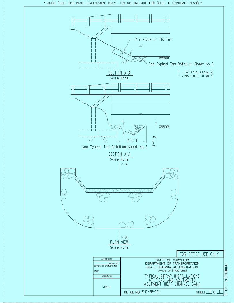
PEFND-SP-201DETAIL NO. 2
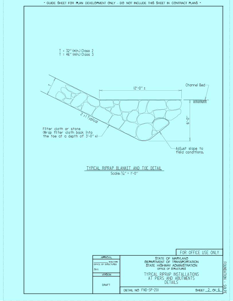
TYPICAL RIPRAP INSTALLATIONSAT PIERS AND ABUTMENTS
6’-
0’’
Channel Bed
DETAILS
Adjust slope to
field conditions.
12’-0’’ +-
Filter cloth or stone
(Wrap filter cloth back into
the toe at a depth of 3’-0’’ +)-
TT = 32’’ (min.) Class 2
T = 46’’ (min.) Class 3
Scale: 1/4 ’’ = 1’-0’’
TYPICAL RIPRAP BLANKET AND TOE DETAIL
2 : 1 Typical
VERSION
FOR OFFICE USE ONLY
OFFICE OF STRUCTURES
DIRECTOR
OFFICE OF STRUCTURES
DRAFT
6
DATE:
STATE HIGHWAY ADMINISTRATION
DEPARTMENT OF TRANSPORTATION
STATE OF MARYLAND
SHEET OF
APPROVAL
* GUIDE SHEET FOR PLAN DEVELOPMENT ONLY - DO NOT INCLUDE THIS SHEET IN CONTRACT PLANS *
FO
UN
DA
TIO
N - S
OL
PEFND-SP-201DETAIL NO. 3
TYPICAL RIPRAP INSTALLATIONSAT PIERS AND ABUTMENTS
T = 32’’ (min.) Class 2
T = 46’’ (min.) Class 3
TT
2 : 1 slope or flatter
See Typical Toe Detail on Sheet No. 2
12’-0’’ +-
6’-
0’’
+-
A
A
ABUTMENT NEAR CHANNEL BANK
See Typical Toe Detail on Sheet No. 2
SECTION A-A
Scale: None
SECTION A-A
Scale: None
Scale: None
PLAN VIEW
VERSION
OFFICE OF STRUCTURES
DIRECTOR
OFFICE OF STRUCTURES
DRAFT
FOR OFFICE USE ONLY
6
DATE:
STATE HIGHWAY ADMINISTRATION
DEPARTMENT OF TRANSPORTATION
STATE OF MARYLAND
SHEET OF
APPROVAL
* GUIDE SHEET FOR PLAN DEVELOPMENT ONLY - DO NOT INCLUDE THIS SHEET IN CONTRACT PLANS *
FO
UN
DA
TIO
N - S
OL
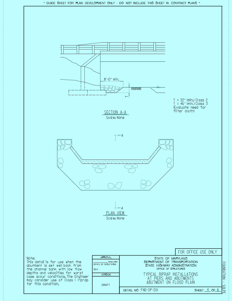
PEFND-SP-201DETAIL NO. 4
Note:
This detail is for use when the
abutment is set well back from
the channel bank with low flow
depths and velocities for worst
case scour conditions. The Engineer
may consider use of Class 1 riprap
for this condition.
A
A
SECTION A-A
Scale: None
Scale: None
PLAN VIEW
T = 32’’ (min.) Class 2
T = 46’’ (min.) Class 3
(Evaluate need for
filter cloth)
T
8’-0’’ min.
TYPICAL RIPRAP INSTALLATIONSAT PIERS AND ABUTMENTS
ABUTMENT ON FLOOD PLAIN
VERSION
DRAFT
DIRECTOR
OFFICE OF STRUCTURES
OFFICE OF STRUCTURES
FOR OFFICE USE ONLY
6
DATE:
STATE HIGHWAY ADMINISTRATION
DEPARTMENT OF TRANSPORTATION
STATE OF MARYLAND
SHEET OF
APPROVAL
* GUIDE SHEET FOR PLAN DEVELOPMENT ONLY - DO NOT INCLUDE THIS SHEET IN CONTRACT PLANS *
FO
UN
DA
TIO
N - S
OL
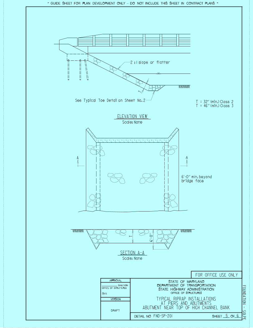
PEFND-SP-201DETAIL NO. 5
Scale: None
T
T = 32’’ (min.) Class 2
T = 46’’ (min.) Class 3
2 : 1 slope or flatter
See Typical Toe Detail on Sheet No. 2
A A
T
6’-
0’’
SECTION A-A
Scale: None
ELEVATION VIEW
6’-0’’ min. beyond
bridge face
TYPICAL RIPRAP INSTALLATIONSAT PIERS AND ABUTMENTS
ABUTMENT NEAR TOP OF HIGH CHANNEL BANK
VERSION
DRAFT
FOR OFFICE USE ONLY
DIRECTOR
OFFICE OF STRUCTURES
OFFICE OF STRUCTURES
6
DATE:
STATE HIGHWAY ADMINISTRATION
DEPARTMENT OF TRANSPORTATION
STATE OF MARYLAND
SHEET OF
APPROVAL
* GUIDE SHEET FOR PLAN DEVELOPMENT ONLY - DO NOT INCLUDE THIS SHEET IN CONTRACT PLANS *
FO
UN
DA
TIO
N - S
OL
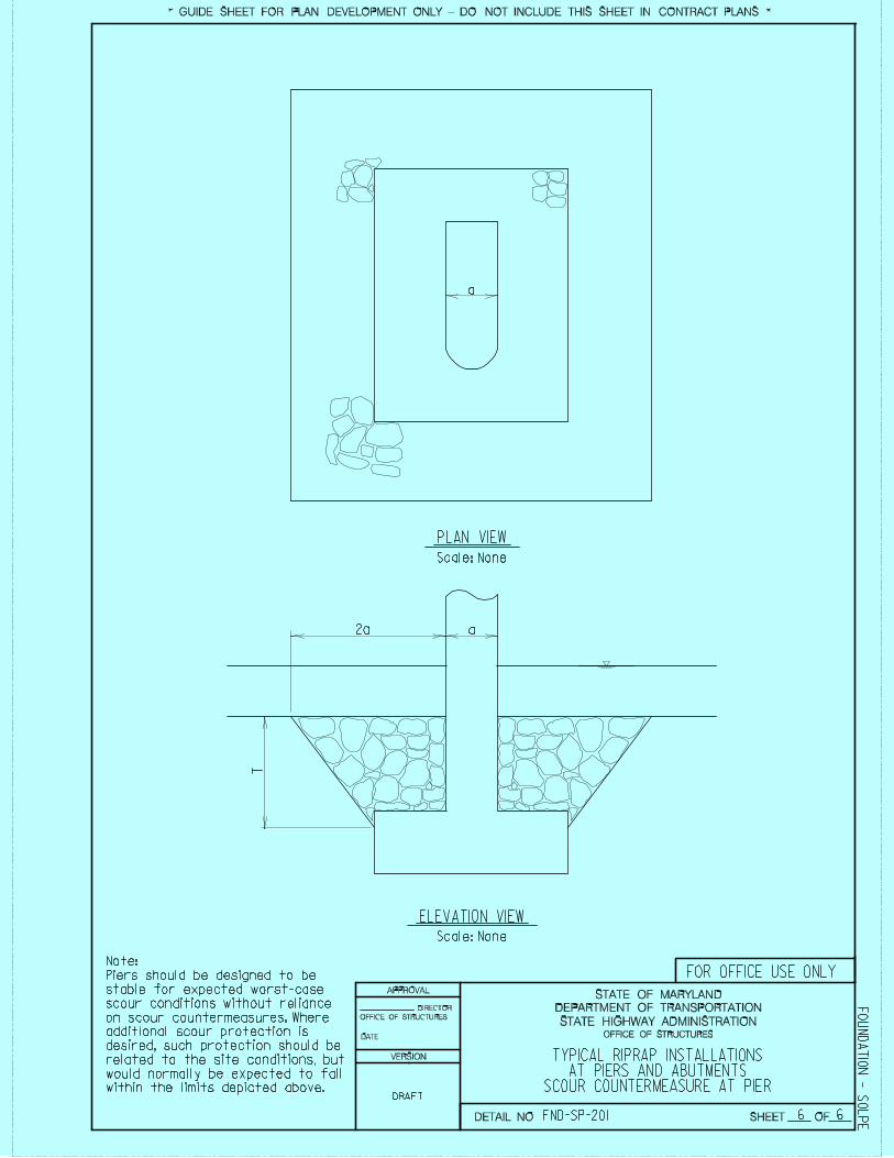
PEFND-SP-201DETAIL NO.
Note:
Piers should be designed to be
stable for expected worst-case
scour conditions without reliance
on scour countermeasures. Where
additional scour protection is
desired, such protection should be
related to the site conditions, but
would normally be expected to fall
within the limits depicted above.
2a a
T
a
Scale: None
PLAN VIEW
Scale: None
ELEVATION VIEW
6
TYPICAL RIPRAP INSTALLATIONSAT PIERS AND ABUTMENTS
SCOUR COUNTERMEASURE AT PIER
VERSION
FOR OFFICE USE ONLY
OFFICE OF STRUCTURES
DIRECTOR
OFFICE OF STRUCTURES
DRAFT