challenges for rechargeable li batteries 2009
TRANSCRIPT
pubs.acs.org/cmPublished on Web 08/28/2009r 2009 American Chemical Society
Chem. Mater. 2010, 22, 587–603 587DOI:10.1021/cm901452z
Challenges for Rechargeable Li Batteries†
John B. Goodenough* and Youngsik Kim
Texas Materials Institute, University of Texas at Austin, Austin, Texas 78712
Received May 27, 2009. Revised Manuscript Received July 9, 2009
The challenges for further development of Li rechargeable batteries for electric vehicles arereviewed. Most important is safety, which requires development of a nonflammable electrolyte witheither a larger window between its lowest unoccupied molecular orbital (LUMO) and highestoccupied molecular orbital (HOMO) or a constituent (or additive) that can develop rapidly a solid/electrolyte-interface (SEI) layer to prevent plating of Li on a carbon anode during a fast charge of thebattery. A high Liþ-ion conductivity (σLi > 10-4 S/cm) in the electrolyte and across the electrode/electrolyte interface is needed for a power battery. Important also is an increase in the density of thestored energy, which is the product of the voltage and capacity of reversible Li insertion/extractioninto/from the electrodes. It will be difficult to design a better anode than carbon, but carbon requiresformation of an SEI layer, which involves an irreversible capacity loss. The design of a cathodecomposed of environmentally benign, low-cost materials that has its electrochemical potential μCwell-matched to the HOMOof the electrolyte and allows access to two Li atoms per transition-metalcation would increase the energy density, but it is a daunting challenge. Two redox couples can beaccessed where the cation redox couples are “pinned” at the top of the O 2p bands, but to takeadvantage of this possibility, it must be realized in a framework structure that can accept more thanone Li atom per transition-metal cation. Moreover, such a situation represents an intrinsic voltagelimit of the cathode, and matching this limit to the HOMO of the electrolyte requires the ability totune the intrinsic voltage limit. Finally, the chemical compatibility in the battery must allow a longservice life.
Introduction
It is now almost universally recognized that gaseousemissions from the burning of fossil fuels and biomass arenot only polluting the air of large, modern cities but arealso creating a global warming with alarming conse-quences. Moreover, a dependence on foreign oil and/orgas creates national vulnerabilities that endanger socialstability. These concerns are concentrating attention onceagain on national initiatives to reevaluate utilization ofalternative energy sources and replacement of the internalcombustion engine with a wireless electric motor.Solar radiation, wind, and waves represent energy
sources that are variable in time and diffuse in space.1
These sources require energy storage. Nuclear reactorsprovide a constant energy source with associated pro-blems of radioactive waste disposal.Geothermal energy isrestricted in location. These energy sources also benefitfrom electrical energy storage. The energy carriers are theelectricity grid, electromagnetic waves, and chemical en-ergy. The most convenient form of energy storage isportable chemical energy, which is the reason for ouraddiction to fossil fuels for heat, propulsion, lighting, andcommunication. The battery provides the portability of
stored chemical energy with the ability to deliver thisenergy as electrical energy with a high conversion effi-ciency and no gaseous exhaust. Moreover, the alternativeenergy sources are preferably converted to d.c. electricalenergy well-matched to storage as chemical energy in abattery. Whereas alternative energy sources are station-ary, which allows other means of energy storage to becompetitive with a battery, electric vehicles require theportable stored energy of a fuel fed to a fuel cell or of abattery. Therefore, of particular interest is a low-cost,safe, rechargeable (secondary) battery of high voltage,capacity, and rate capability.The higher stored volume and gravimetric energy
density of a Li battery has enabled realization of thecellular telephone and lap-top computer. However, cost,safety, stored energy density, charge/discharge rates, andservice life are issues that continue to plague the develop-ment of the Li battery for the potential mass market ofelectric vehicles to alleviate distributed CO2 emissionsand noise pollution.2
A battery consists of a group of interconnected electro-chemical cells. Here, we focus on batteries for electricvehicles where cost, gravimetric energy density, and theperformance uniformity of individual cells in a large,multicell battery are of more concern than the volumeenergy density considered critical for hand-held appli-ances. Moreover, we consider only the choice of activematerials in the individual cells of a secondary battery,
†Accepted as part of the 2010 “Materials Chemistry of Energy ConversionSpecial Issue”.
*Author to whom correspondence should be directed. E-mail:[email protected].
588 Chem. Mater., Vol. 22, No. 3, 2010 Goodenough and Kim
viz. the anode (negative electrode), the cathode (positiveelectrode), and the electrolyte between the electrodes.
Preliminary Considerations
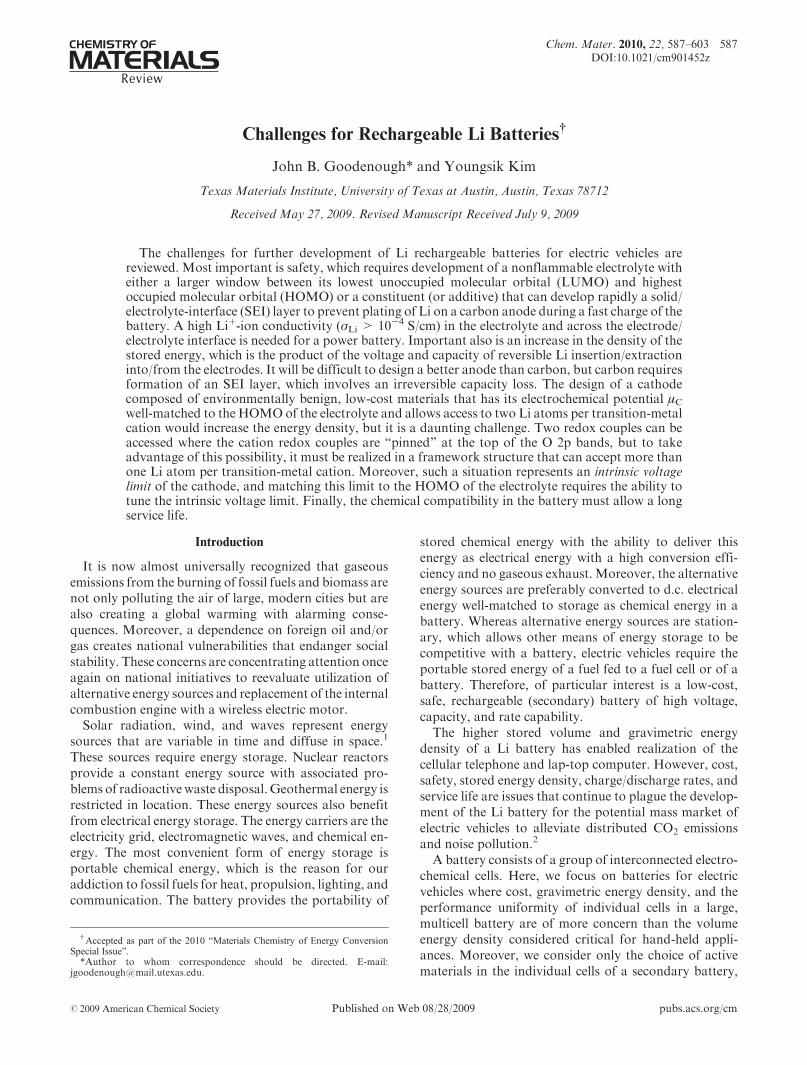
Figure 1 is a schematic of the relative electron energiesin the electrodes and the electrolyte of a thermodynami-cally stable battery cell having an aqueous electrolyte.The anode is the reductant, the cathode is the oxidant,and the energy separation Eg of the lowest unoccupiedmolecular orbital (LUMO) and the highest occupiedmolecular orbital (HOMO) of the electrolyte is the “win-dow” of the electrolyte. The two electrodes are electronicconductors with anode and cathode electrochemicalpotentials μA and μC (their Fermi energies εF). An anodewith a μA above the LUMO will reduce the electrolyteunless a passivation layer creates a barrier to electrontransfer from the anode to the electrolyte LUMO; acathode with a μC below the HOMO will oxidize theelectrolyte unless a passivation layer blocks electrontransfer from the electrolyte HOMO to the cathode.Therefore, thermodynamic stability requires locatingthe electrode electrochemical potentials μA and μC withinthe window of the electrolyte, which constrains the open-circuit voltage Voc of a battery cell to
eVoc ¼ μA -μCeEg ð1Þ
where e is the magnitude of the electron charge. Apassivating solid/electrolyte-interface (SEI) layer at theelectrode/electrolyte boundary can give a kinetic stabilityto a larger Voc provided that eVoc - Eg is not too large.On discharge, electrons leave the anode via an external
circuit where they do useful work before entering thecathode. To retain charge neutrality in the electrodes,cations are released from the anode to the electrolyte andthe working cation of the electrolyte, the Hþ ion in anaqueous electrolyte, carries positive charge to the cathodeto provide charge neutrality in the cathode. The process isreversed on charge in a rechargeable (secondary) battery.The energy density of a battery cell is ΛVoc; Λ is the
capacity of reversible charge transfer per unit weight (Ah/g) between the anode and cathode. Λ decreases with therate of charge or discharge, i.e. the magnitude of theelectronic current in the external circuit, which must bematched by the internal ionic current within the battery.Since the ionic current density of the electrolyte andelectrodes, including the rate of ion transfer across theelectrode/electrolyte interface, is much smaller thanthe electronic current density, the electrodes and electro-lyte have a large surface area and a small thickness.Nevertheless, at high current densities, the ionic motionwithin an electrode and/or across an electrode/electrolyteinterface is too slow for the charge distribution to reachequilibrium, which is why the reversible capacity de-creases with increasing current density in the batteryand why this capacity loss is recovered on reducing therate of charge and/or discharge.The high Hþ-ion conductivity required of an aqueous
electrolyte over the practical ambient-temperature range
is only found in liquid or immobilized-liquid water, andan Eg ≈ 1.3 eV for an aqueous electrolyte limits Voc. Inorder to obtain a cell with a higher Voc and therefore ahigher energy density ΛVoc, it is necessary to turn to anonaqueous electrolyte with a larger Eg. This observa-tion, in turn, has led to the Liþ-ion battery since lithiumsalts are soluble in some nonaqueous liquids and poly-mers. However, in this case, the HOMO of the salt as wellas that of the solvent may determine the limiting μC of thecathode.Once the window of the Liþ-ion electrolyte has been
determined, it is necessary to design electrodes of highcapacity that have their μA and μCmatched to the LUMOandHOMOof the electrolyte. Elemental Li0 would be theideal anode, but the εF= μA of Li0 lies above the LUMOof practical, known nonaqueous electrolytes. Therefore,use of Li0 as an anode is only possible because a passivat-ing SEI layer is formed. The SEI layer allows use of Li0 asan anode in half-cells used to obtain the μA or μC of apractical electrode relative to the Liþ/Li0 energy level; buton repeated charge/discharge cycles, breaking of the SEIlayer in selected areas results in the formation of dendritesthat can grow across the electrolyte to short-circuit a cellof the battery with dangerous consequences. Therefore,we must design either (1) an anode with a μA matched tothe LUMOof the electrolyte aswell as a cathodewith a μCmatched to the HOMO of the electrolyte or (2) a stablepassivating SEI layer that self-heals rapidly when brokenby the changes in electrode volume that occur in a charge/discharge cycle; the SEI layer must also permit a fast Liþ-ion transfer between the electrode and the electrolytewithout blocking electron transfer between the activeparticle and the current collector.In summary, the formidable challenges for the devel-
oper of a rechargeable Li battery for the potentialmass market of electric vehicles are three-fold: to identify
Figure 1. Schematic open-circuit energy diagram of an aqueous electro-lyte. ΦA and ΦC are the anode and cathode work functions. Eg is thewindow of the electrolyte for thermodynamic stability. A μA > LUMOand/or a μC <HOMO requires a kinetic stability by the formation of anSEI layer.
Review Chem. Mater., Vol. 22, No. 3, 2010 589
low-cost, environmentally benign materials for thethree active components of a battery cell, viz. (1) anonaqueous electrolyte of high Liþ-ion conductivity(σLi>10-3 S/cm) over the practical ambient-temperaturerange -40 < T < 60 �C that has a window allowinga thermodynamically stable Voc g 4 V and (2) an anodeand (3) a cathode with their μA and μC values well-matched to the window of the electrolyte as well as eachallowing a fast charge/discharge cycle of large reversiblecapacity.
Electrolytes
In addition to a large electrolyte window Eg, theelectrolyte must satisfy several additional requirementssuch as:
1) Retention of the electrode/electrolyte interfaceduring cycling when the electrode particles arechanging their volume.
2) A Liþ-ion conductivity σLi>10-4 S/cm over thetemperature range of battery operation.
3) An electronic conductivity σe<10-10 S/cm.4) A transference number σLi/σtotal ≈ 1, where σtotal
includes conductivities by other ions in the elec-trolyte as well as σLi þ σe.
5) Chemical stability over ambient temperature rangesand temperatures in the battery under high power.
6) Chemical stability with respect to the electrodes,including the ability to form rapidly a passiva-ting solid/electrolyte-interface (SEI) layer where
kinetic stability is required because the electrodepotential lies outside the electrolyte window.
7) Safe materials, i.e., preferably nonflammable andnonexplosive if short-circuited.
8) Low toxicity and low cost.Meeting all these requirements proves to be aformidable challenge.
Types of Electrolytes. In general, the electrolyte isspecifically designed for a particular battery application.Table 1 shows several different materials that have beenused as electrolytes for Li batteries.
Organic Liquid Electrolytes. Carbonates are orga-nic liquids that are reasonably good solvents for Li
salts.3,4 They have an oxidation potential (HOMO) at
ca. 4.7 V3,5,6 and a reduction potential (LUMO) near 1.0
V.7 (All voltages in this paper are referred to the Liþ/Li0
potential.) Moreover, they have a relatively low viscos-
ity, which results in a low activation energy for Liþ-iondiffusion. Therefore, the most commonly used electro-
lytes are carbonates or carbonate blends consisting of
one or more of the following: propylene carbonate (PC),
ethylene carbonate (EC), diethyl carbonate (DEC),
dimethyl carbonate (DMC), or ethylmethyl carbonate
(EMC). In order to be able to use carbon as the anode,
which has its electrochemical potential above (at a
lower voltage versus Liþ/Li0) that of the LUMO of a
carbonate, the solvents include, in most cases, ethylenecarbonate (EC) because the EC provides a passivating
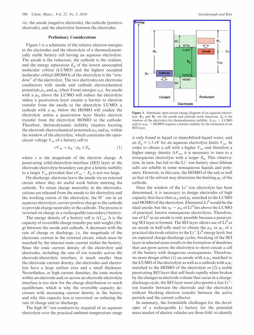
Table 1. Nonaqueous Electrolytes for Li-Ion Batteries
Electrolytes Example of classical electrolytes
Ionic conductivity(� 10-3 s/cm)at room temp
Electrochemicalwindow (V) vs Liþ/Li0
RemarkReduction Oxidation
Liquid organic 1M LiPF6 in EC:DEC (1:1) 73 1.37 4.56 Flammable1M LiPF6 in EC:DMC (1:1) 103 1.37 >5.03
Ionic liquids 1M LiTFSI in EMI-TFSI 2.015 1.015 5.315 Non-flammable1M LiBF4 in EMI-BF4 8.015 0.916 5.316
Polymer LiTFSI-P(EO/MEEGE) 0.124 <0.024 4.724 FlammableLiClO4-PEO8 þ 10 wt % TiO2 0.0226 <0.026 5.026
Inorganic solid Li4-xGe1-xPxS4 (x = 0.75) 2.228 <0.028 >5.028 Non-flammable0.05Li4SiO4 þ 0.57Li2S þ 0.38SiS2 1.030 <0.030 >8.030
Inorganic liquid LiAlCl4 þ SO2 7020 - 4.420 Non-flammable
Liquid organic þPolymer
0.04LiPF6 þ 0.2EC þ 0.62DMC þ0.14PAN
4.238 - 4.438 Flammable
LiClO4 þ EC þ PC þ PVdF 3.039 - 5.039
Ionic liquid þPolymer
1M LiTFSI þ P13TFSI þPVdF-HFP
0.1843 <0.043 5.843 Less flammable
Ionic liquid þ Polymerþ Liquid organic
56 wt % LiTFSI-Py24TFSI þ30 wt % PVdF-HFP þ14 wt % EC/PC
0.8144 1.544 4.2 44 Less flammable
Polymerþ Inorganic solid
2 vol % LiClO4-TEC-19 þ 98 vol%95 (0.6Li2S þ 0.4Li2S) þ 5Li4SiO4
0.0346 <0.046 >4.546 Non-flammable
Ionic liquid þ Liquid organic19 - - - Non-flammable
590 Chem. Mater., Vol. 22, No. 3, 2010 Goodenough and Kim
solid/electrolyte-interface (SEI) layer on the surface of acarbon anode that protects the electrolytes from furtherdecomposition after SEI formation.8,9 However, carbo-nate-based solvents are highly flammable with flashpoints below 30 �C.10 In addition, the preferred salt,LiPF6, can undergo an autocatalytic decomposition intoLiF and PF5; the PF5 reacts irreversibly with any waterpresent (PF5 þ H2O=PF3O þ 2HF) and, above 60 �C,with a carbonate electrolyte.11 These reactions degradethe battery and lead to safety hazards. However, addi-tives used to lower the operating temperature have beenshown to prevent the autocatalytic decomposition ofLiPF6 salt.
12
Ionic Liquids. Room-temperature ionic liquids(RTILs)13-17 have been recently considered as alternativeelectrolytes for Li-ion batteries because they offer severaladvantages over carbonate-based electrolytes: a highoxidation potential (∼5.3 V vs Liþ/Li0), nonflammabil-ity, a low vapor pressure, better thermal stability, lowtoxicity, high boiling points, and a high Li-salt solubility.Unfortunately, they have a higher viscosity, which re-duces their Liþ-ion conductivity. Ionic liquids based onimidazolium-based cations would appear to be the mostappropriate candidates for Li batteries due to their lowerviscosity and a high Li-salt solubility at room tempera-ture. However, these ionic liquids have poor stability atvoltages below 1.1 V,18 so that additives such as ECorVCmust be added to introduce a stable SEI layer on a carbonanode. An alternative approach is to increase σLi byadding a liquid carbonate to an ionic liquid, but at aconcentration that retains the nonflammability of theionic liquid.19 With this strategy, it is also possible toincrease the oxidation voltage (lower HOMO energy) ofthe hybrid electrolyte from that of the carbonate. In spiteof extensive research, no RTILs have yet been introducedinto large power batteries.
Inorganic Liquid Electrolytes. The inorganic liquidelectrolyte based on LiAlCl4 and SO2 proposed by Stas-sen and Hambitzer20,21 has a good room-temperatureσLi=7 � 10-2 S/cm and is nonflammable, but its electro-lyte window appears to be too small to be competitive.
Solid Polymer Electrolytes. A solid electrolyte can actas the separator of the electrodes, and a solid polymerelectrolyte can also retain contact over an electrode/electrolyte interface during modest changes of the elec-trode volume with the state of charge of the battery.Polyethylene oxides (PEOs) containing a lithium salt(LiPF6 or LiAsF6)
22-24 are low-cost, nontoxic, Liþ-ionpolymer electrolytes with good chemical stability, but theLiþ-ion conductivity, σLi<10-5 S/cm at room tempera-ture, is too low for a power-battery system. The introduc-tion of oxide particles (e.g., Al2O3, TiO2, SiO2, orZrO2)
25-27 creates a more amorphous polymer matrixby inhibiting chain crystallization and attracting Liþ
from its salt. The result is an enhanced σLi and Li-iontransference number, but σLi is still not comparable tothat of the carbonate electrolytes.
Inorganic Solid Electrolytes. Inorganic solid Liþ-ionconducting materials having a σLi>10-4 S/cm28-31 have
been considered for Li-based electrolytes, as has beenextensively reviewed,32 because they have a wide electro-chemical window and additionally meet the electrolyterequirements from 2 to 7, not 1. For these reasons,laboratory-size all-solid-state Li-ion batteries have beeninvestigated.33-35 However, the first of the additionalelectrolyte requirements has excluded inorganic solidLiþ-ion electrolytes from consideration for large-scalebatteries having solid electrodes. They have only beenused in thin-film battery applications.36
Hybrid Electrolyte System. Hybrid electrolytes areblends of organic liquid electrolytes, ionic liquids, poly-mer electrolytes, and/or inorganic solid electrolytes:
Polymer þ organic liquid (polymer gel)37-40
Ionic liquid þ polymer electrolyte (ionic liquid poly-mer gel)41-45
Ionic liquid þ polymer electrolyte þ liquid organicelectrolyte43,44
Ionic liquid þ liquid organic electrolyte19
Polymer electrolyte þ inorganic solid electrolyte46-48
The mixtures of two or more electrolytes are investi-
gated in attempts to exploit the advantages of each
constituent, but the disadvantages of each also appear.
For example, the ionic conductivity is increased in the
polymer gel electrolytes, but they are still flammable and
have the irreversible capacity loss below 1 V associated
with formation of a passivation layer.40
Electrode-Electrolyte Compatibility. Although ther-modynamic stability of the electrolyte vis �a vis the elec-trodes is possible where the μA and μC of the electrodes liewithin the window of the electrolyte, nevertheless chemi-cal reactions between the electrode and the electrolytemay occur. For example, the reversible electrochemicalintercalation of Li into LixVS2 was originally frustratedby use of the electrolyte LiClO4 in PC,49 but the electro-lyte LiPF6 in EC/DEC allows full electrochemical cyclingbetween LiVS2 and VS2.
50
The cathode spinel Li1-x[Mn2]O4 provides anothertype of electrode-electrolyte reaction; an electrode sur-face disproportionation reaction 2Mn3þ=Mn2þþMn4þ
results in dissolution of the Mn2þ from the electrode intothe electrolyte.51 This reaction, unless suppressed, givesan irreversible capacity loss of the cathode and migrationof the Mn2þ across the electrolyte to the anode duringcharge to block Liþ-ion insertion into the anode. Theresult is an intolerable limitation of the service life ofthe cell.In addition to chemical stability vis �a vis the electrodes
and higher temperatures, the electrolyte should not be
decomposed by an anode μA at a higher energy than the
electrolyte LUMOor a cathode μC at a lower energy than
the HOMO. However, if μA or μC lie outside the window
of the electrolyte, kinetic stability may be achieved by
formation of a passivating SEI layer on the surface of the
electrode, but at the expense of the loss in capacity to form
the layer. Moreover, during a fast charge, the concentra-tion of Liþ ions may build up on the surface of the SEIlayer, and where a change in volume of the electrode
Review Chem. Mater., Vol. 22, No. 3, 2010 591
breaks the SEI layer, Li0 may be plated out before thebreak is healed. Li plating can result in dendrites thatgrow across the electrolyte. This problem creates a safetyissue that has haunted the use of a carbon anode in large-scale power batteries. These problems need to be mana-ged if safety standards are to be met with any anode,including carbon, that has its μA above the LUMO of theelectrolyte.A cathode μC at a lower energy than the electrolyte
HOMO must be distinguished from an intrinsic voltagelimit of the cathode, as is discussed below. As withanodes, passivating layers on cathodes are best formedin situ so that electronic contact with the cathode currentcollector is not broken. Preliminary work52-54 on pas-sivating SEI layers on oxide cathodes has found themto be unstable. This field has yet to be adequatelyresearched.
Electrodes
The design of an electrode involves tailoring of the μAof an anode or μC of a cathode to the LUMO or HOMOof the Liþ-ion electrolyte to be used; the electrode must
also be chemically stable in the electrolyte. To date,practical electrodes have all had host structures into/fromwhich guest Li atoms can be inserted/extracted reversibly.Factors Determining μA and μC. The energy of a given
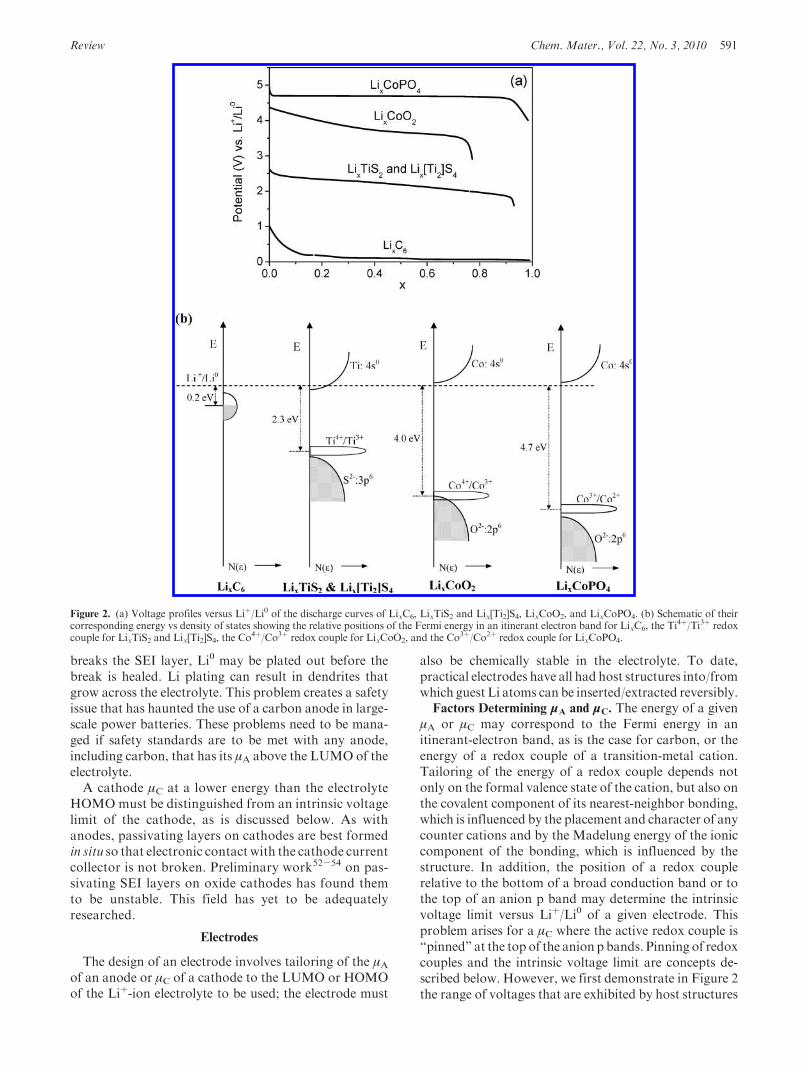
μA or μC may correspond to the Fermi energy in anitinerant-electron band, as is the case for carbon, or theenergy of a redox couple of a transition-metal cation.Tailoring of the energy of a redox couple depends notonly on the formal valence state of the cation, but also onthe covalent component of its nearest-neighbor bonding,which is influenced by the placement and character of anycounter cations and by the Madelung energy of the ioniccomponent of the bonding, which is influenced by thestructure. In addition, the position of a redox couplerelative to the bottom of a broad conduction band or tothe top of an anion p band may determine the intrinsicvoltage limit versus Liþ/Li0 of a given electrode. Thisproblem arises for a μC where the active redox couple is“pinned” at the top of the anion p bands. Pinning of redoxcouples and the intrinsic voltage limit are concepts de-scribed below. However, we first demonstrate in Figure 2the range of voltages that are exhibited by host structures
Figure 2. (a) Voltage profiles versus Liþ/Li0 of the discharge curves of LixC6, LixTiS2 and Lix[Ti2]S4, LixCoO2, and LixCoPO4. (b) Schematic of theircorresponding energy vs density of states showing the relative positions of the Fermi energy in an itinerant electron band for LixC6, the Ti
4þ/Ti3þ redoxcouple for LixTiS2 and Lix[Ti2]S4, the Co
4þ/Co3þ redox couple for LixCoO2, and the Co3þ/Co2þ redox couple for LixCoPO4.
592 Chem. Mater., Vol. 22, No. 3, 2010 Goodenough and Kim
into/from which Liþ ions have been inserted reversibly.Carbon, LixTiS2, and LixCoO2 are all layered com-pounds, the [Ti2]S4 spinel host of Lix[Ti2]S4 is stronglybonded in 3D, and LixCoPO4 shows the influence of thecountercation of the (PO4)
3- polyanion on the Co3þ/Co2þ couple relative to the Co4þ/Co3þ couple in thelayered LixCoO2 (charges on ions represent formalvalence states, not actual charges). The upper voltagelimits in the sulfides are much lower than those in theoxides. In Figure 3, we also show how the Mn4þ/Mn3þ
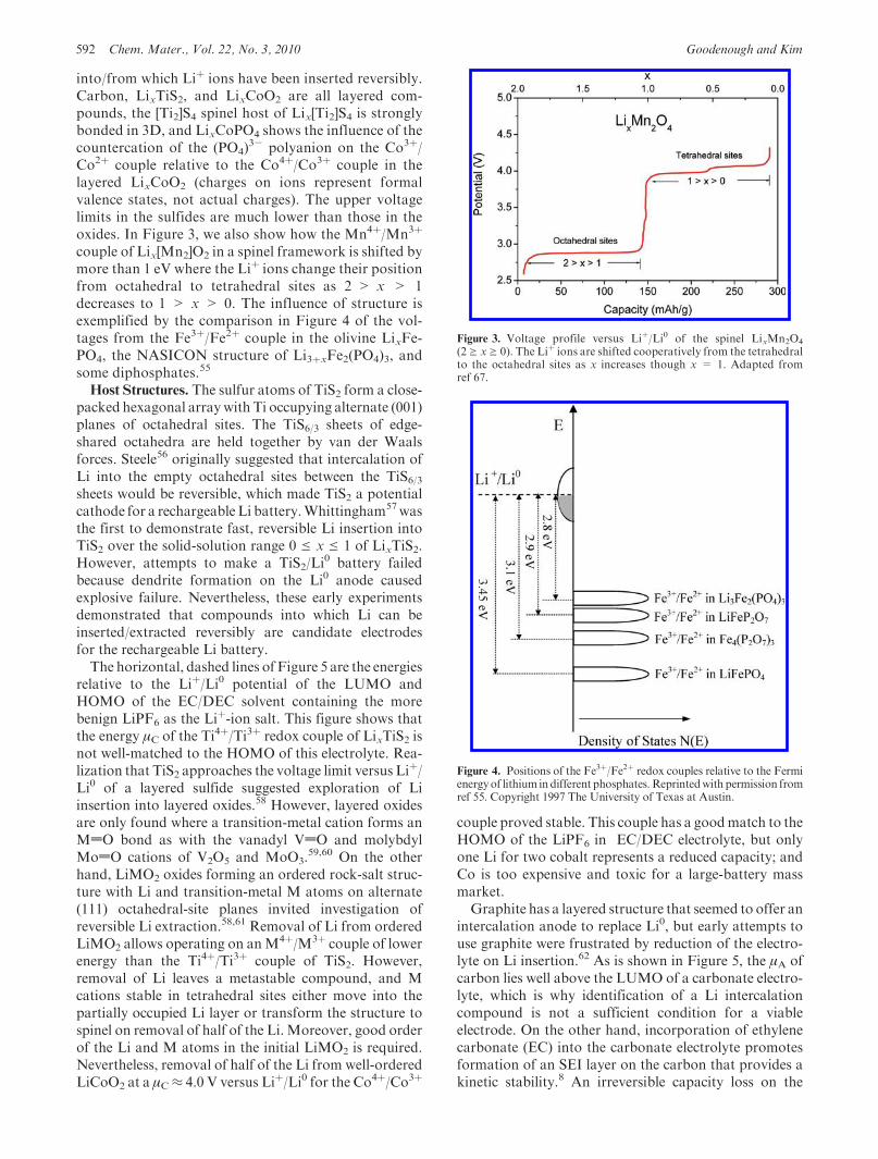
couple of Lix[Mn2]O2 in a spinel framework is shifted bymore than 1 eV where the Liþ ions change their positionfrom octahedral to tetrahedral sites as 2 > x > 1decreases to 1 > x > 0. The influence of structure isexemplified by the comparison in Figure 4 of the vol-tages from the Fe3þ/Fe2þ couple in the olivine LixFe-PO4, the NASICON structure of Li3þxFe2(PO4)3, andsome diphosphates.55
Host Structures. The sulfur atoms of TiS2 form a close-packed hexagonal arraywith Ti occupying alternate (001)planes of octahedral sites. The TiS6/3 sheets of edge-shared octahedra are held together by van der Waalsforces. Steele56 originally suggested that intercalation ofLi into the empty octahedral sites between the TiS6/3sheets would be reversible, which made TiS2 a potentialcathode for a rechargeable Li battery.Whittingham57wasthe first to demonstrate fast, reversible Li insertion intoTiS2 over the solid-solution range 0 e x e 1 of LixTiS2.However, attempts to make a TiS2/Li
0 battery failedbecause dendrite formation on the Li0 anode causedexplosive failure. Nevertheless, these early experimentsdemonstrated that compounds into which Li can beinserted/extracted reversibly are candidate electrodesfor the rechargeable Li battery.The horizontal, dashed lines of Figure 5 are the energies
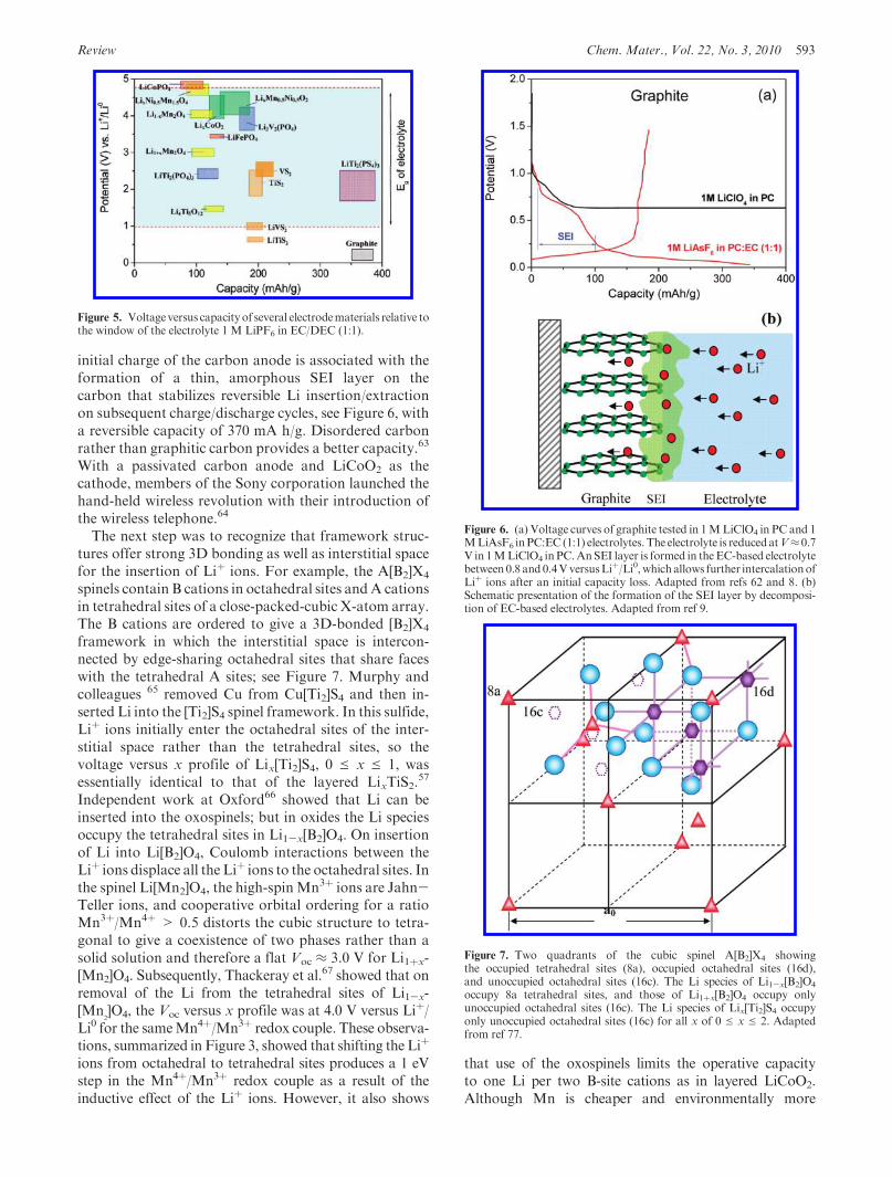
relative to the Liþ/Li0 potential of the LUMO andHOMO of the EC/DEC solvent containing the morebenign LiPF6 as the Li
þ-ion salt. This figure shows thatthe energy μC of the Ti4þ/Ti3þ redox couple of LixTiS2 isnot well-matched to the HOMO of this electrolyte. Rea-lization that TiS2 approaches the voltage limit versus Liþ/Li0 of a layered sulfide suggested exploration of Liinsertion into layered oxides.58 However, layered oxidesare only found where a transition-metal cation forms anMdO bond as with the vanadyl VdO and molybdylModO cations of V2O5 and MoO3.
59,60 On the otherhand, LiMO2 oxides forming an ordered rock-salt struc-ture with Li and transition-metal M atoms on alternate(111) octahedral-site planes invited investigation ofreversible Li extraction.58,61 Removal of Li from orderedLiMO2 allows operating on anM4þ/M3þ couple of lowerenergy than the Ti4þ/Ti3þ couple of TiS2. However,removal of Li leaves a metastable compound, and Mcations stable in tetrahedral sites either move into thepartially occupied Li layer or transform the structure tospinel on removal of half of the Li. Moreover, good orderof the Li and M atoms in the initial LiMO2 is required.Nevertheless, removal of half of the Li from well-orderedLiCoO2 at a μC≈ 4.0 V versus Liþ/Li0 for the Co4þ/Co3þ
couple proved stable. This couple has a goodmatch to theHOMO of the LiPF6 in EC/DEC electrolyte, but onlyone Li for two cobalt represents a reduced capacity; andCo is too expensive and toxic for a large-battery massmarket.Graphite has a layered structure that seemed to offer an
intercalation anode to replace Li0, but early attempts touse graphite were frustrated by reduction of the electro-lyte on Li insertion.62 As is shown in Figure 5, the μA ofcarbon lies well above the LUMO of a carbonate electro-lyte, which is why identification of a Li intercalationcompound is not a sufficient condition for a viableelectrode. On the other hand, incorporation of ethylenecarbonate (EC) into the carbonate electrolyte promotesformation of an SEI layer on the carbon that provides akinetic stability.8 An irreversible capacity loss on the
Figure 3. Voltage profile versus Liþ/Li0 of the spinel LixMn2O4
(2g xg 0). The Liþ ions are shifted cooperatively from the tetrahedralto the octahedral sites as x increases though x = 1. Adapted fromref 67.
Figure 4. Positions of the Fe3þ/Fe2þ redox couples relative to the Fermienergyof lithium in different phosphates.Reprintedwith permission fromref 55. Copyright 1997 The University of Texas at Austin.
Review Chem. Mater., Vol. 22, No. 3, 2010 593
initial charge of the carbon anode is associated with theformation of a thin, amorphous SEI layer on thecarbon that stabilizes reversible Li insertion/extractionon subsequent charge/discharge cycles, see Figure 6, witha reversible capacity of 370 mA h/g. Disordered carbonrather than graphitic carbon provides a better capacity.63
With a passivated carbon anode and LiCoO2 as thecathode, members of the Sony corporation launched thehand-held wireless revolution with their introduction ofthe wireless telephone.64
The next step was to recognize that framework struc-tures offer strong 3D bonding as well as interstitial spacefor the insertion of Liþ ions. For example, the A[B2]X4
spinels contain B cations in octahedral sites andA cationsin tetrahedral sites of a close-packed-cubic X-atom array.The B cations are ordered to give a 3D-bonded [B2]X4
framework in which the interstitial space is intercon-nected by edge-sharing octahedral sites that share faceswith the tetrahedral A sites; see Figure 7. Murphy andcolleagues 65 removed Cu from Cu[Ti2]S4 and then in-serted Li into the [Ti2]S4 spinel framework. In this sulfide,Liþ ions initially enter the octahedral sites of the inter-stitial space rather than the tetrahedral sites, so thevoltage versus x profile of Lix[Ti2]S4, 0 e x e 1, wasessentially identical to that of the layered LixTiS2.
57
Independent work at Oxford66 showed that Li can beinserted into the oxospinels; but in oxides the Li speciesoccupy the tetrahedral sites in Li1-x[B2]O4. On insertionof Li into Li[B2]O4, Coulomb interactions between theLiþ ions displace all the Liþ ions to the octahedral sites. Inthe spinel Li[Mn2]O4, the high-spinMn3þ ions are Jahn-Teller ions, and cooperative orbital ordering for a ratioMn3þ/Mn4þ > 0.5 distorts the cubic structure to tetra-gonal to give a coexistence of two phases rather than asolid solution and therefore a flat Voc ≈ 3.0 V for Li1þx-[Mn2]O4. Subsequently, Thackeray et al.
67 showed that onremoval of the Li from the tetrahedral sites of Li1-x-[Mn
2]O4, the Voc versus x profile was at 4.0 V versus Liþ/
Li0 for the sameMn4þ/Mn3þ redox couple. These observa-tions, summarized in Figure 3, showed that shifting the Liþ
ions from octahedral to tetrahedral sites produces a 1 eVstep in the Mn4þ/Mn3þ redox couple as a result of theinductive effect of the Liþ ions. However, it also shows
that use of the oxospinels limits the operative capacityto one Li per two B-site cations as in layered LiCoO2.Although Mn is cheaper and environmentally more
Figure 5. Voltageversus capacityof several electrodematerials relative tothe window of the electrolyte 1 M LiPF6 in EC/DEC (1:1).
Figure 6. (a) Voltage curves of graphite tested in 1MLiClO4 in PC and 1MLiAsF6 inPC:EC (1:1) electrolytes. The electrolyte is reducedatV≈ 0.7V in 1MLiClO4 inPC.AnSEI layer is formed in theEC-based electrolytebetween 0.8 and0.4VversusLiþ/Li0, whichallows further intercalationofLiþ ions after an initial capacity loss. Adapted from refs 62 and 8. (b)Schematic presentation of the formation of the SEI layer by decomposi-tion of EC-based electrolytes. Adapted from ref 9.
Figure 7. Two quadrants of the cubic spinel A[B2]X4 showingthe occupied tetrahedral sites (8a), occupied octahedral sites (16d),and unoccupied octahedral sites (16c). The Li species of Li1-x[B2]O4
occupy 8a tetrahedral sites, and those of Li1þx[B2]O4 occupy onlyunoccupied octahedral sites (16c). The Li species of Lix[Ti2]S4 occupyonly unoccupied octahedral sites (16c) for all x of 0 e x e 2. Adaptedfrom ref 77.
594 Chem. Mater., Vol. 22, No. 3, 2010 Goodenough and Kim
benign than Co, it has proven necessary to substitute someLi and Ni forMn to suppress Li order at Li0.5[Mn2]O4 anddissolution of Mn to the electrolyte on repeated charge/discharge cycling; the resulting further loss of capacity isonly partially regained by the ability to replace someoxygen with fluorine.68,69
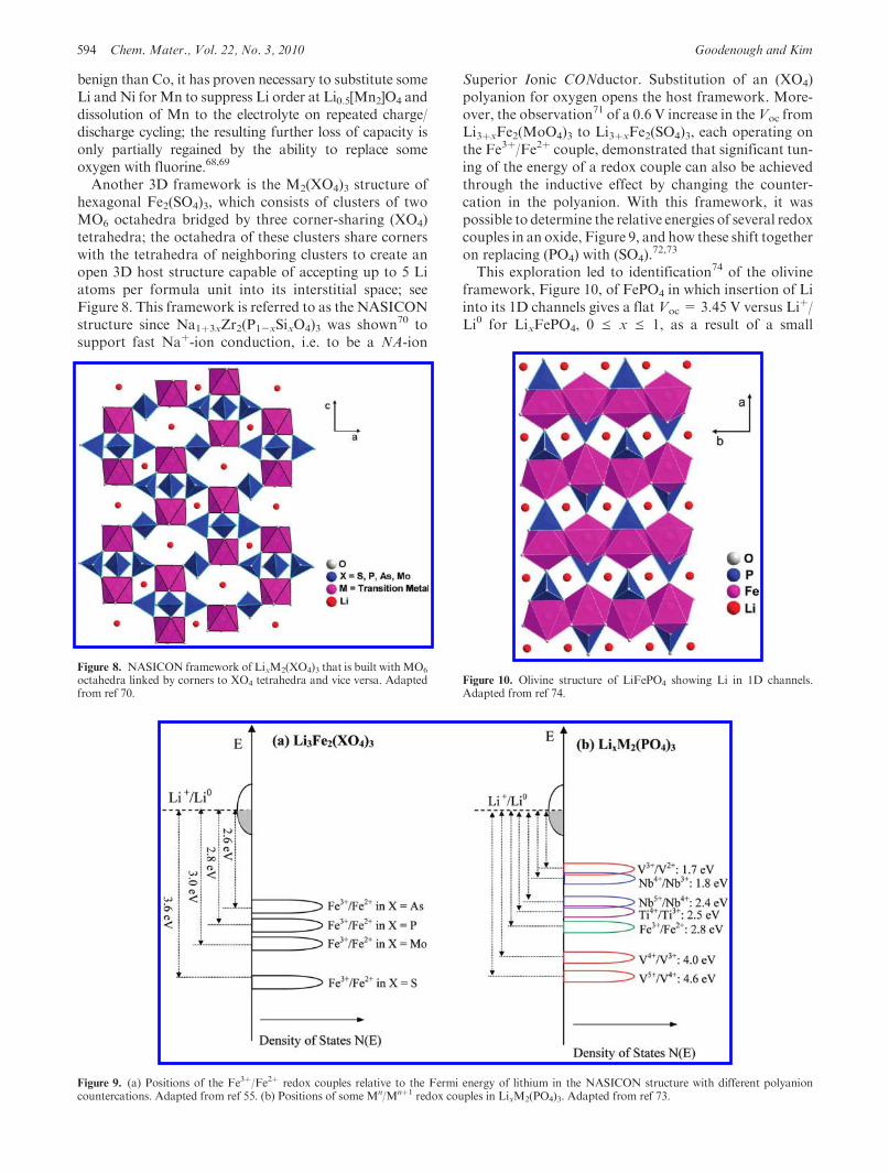
Another 3D framework is the M2(XO4)3 structure ofhexagonal Fe2(SO4)3, which consists of clusters of twoMO6 octahedra bridged by three corner-sharing (XO4)tetrahedra; the octahedra of these clusters share cornerswith the tetrahedra of neighboring clusters to create anopen 3D host structure capable of accepting up to 5 Liatoms per formula unit into its interstitial space; seeFigure 8. This framework is referred to as the NASICONstructure since Na1þ3xZr2(P1-xSixO4)3 was shown70 tosupport fast Naþ-ion conduction, i.e. to be a NA-ion
Superior Ionic CONductor. Substitution of an (XO4)polyanion for oxygen opens the host framework. More-over, the observation71 of a 0.6 V increase in theVoc fromLi3þxFe2(MoO4)3 to Li3þxFe2(SO4)3, each operating onthe Fe3þ/Fe2þ couple, demonstrated that significant tun-ing of the energy of a redox couple can also be achievedthrough the inductive effect by changing the counter-cation in the polyanion. With this framework, it waspossible to determine the relative energies of several redoxcouples in an oxide, Figure 9, and how these shift togetheron replacing (PO4) with (SO4).
72,73
This exploration led to identification74 of the olivineframework, Figure 10, of FePO4 in which insertion of Liinto its 1D channels gives a flat Voc = 3.45 V versus Liþ/Li0 for LixFePO4, 0 e x e 1, as a result of a small
Figure 9. (a) Positions of the Fe3þ/Fe2þ redox couples relative to the Fermi energy of lithium in the NASICON structure with different polyanioncountercations. Adapted from ref 55. (b) Positions of some Mn/Mnþ1 redox couples in LixM2(PO4)3. Adapted from ref 73.
Figure 8. NASICON framework of LixM2(XO4)3 that is built withMO6
octahedra linked by corners to XO4 tetrahedra and vice versa. Adaptedfrom ref 70.
Figure 10. Olivine structure of LiFePO4 showing Li in 1D channels.Adapted from ref 74.
Review Chem. Mater., Vol. 22, No. 3, 2010 595
displacive structural change of the framework betweenLiFePO4 and FePO4. Despite the two-phase character for0< x<1,which results in a poor electronic conductivity,and the 1D channels for the Li motion, small particles ofcarbon-coated C-LixFePO4 result in safe cathodes withreversible capacities that do not fade significantly oncycling thousands of times. However, the Voc is notoptimal for the LiPF6 in the EC/DEC electrolyte. Never-theless, a cell voltage Voc ≈ 3 V can be obtained withLiFePO4 as a cathode and a carbon anode, which isexcellent for many applications. However, to ensuresafety for large-scale power applications, it would bepreferable to have an anode with a μA ≈ 1.3 V versusLiþ/Li0 if LiPF6 in EC/DEC is used as the electrolyte.Such an anode with a LiFePO4 cathode would, however,only give a cellVoc≈ 2 V, whichmight not be competitivewith a nickel/metal-hydride battery having an aqueouselectrolyte.Johnston75 had shown that the spinel Li[Ti2]O4 is a
superconductor and the system Li[LixTi2-x]O4, 0 e x e1/3, had been well-characterized,76,77 but the identifica-tion of Li1þx[Li0.33Ti1.67]O4 as a potential anode with aflat Voc = 1.5 V versus Liþ/Li0 was first made by Ferg etal.78 Although Li4Ti5O12 represents a thermodynamicallystable anode having no passivation layer, it has only amodest capacity and its use as an anode requires identi-fication of a cathode with a better match to the HOMOof the electrolyte than LiFePO4.Intrinsic Voltage Limits. Pinning of a redox couple at
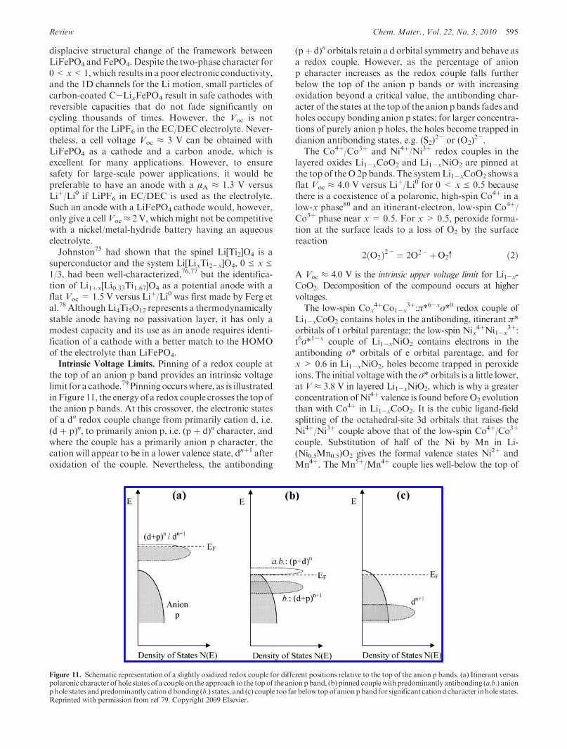
the top of an anion p band provides an intrinsic voltagelimit for a cathode.79 Pinning occurswhere, as is illustratedinFigure 11, the energyof a redox couple crosses the topofthe anion p bands. At this crossover, the electronic statesof a dn redox couple change from primarily cation d, i.e.(d þ p)n, to primarily anion p, i.e. (p þ d)n character, andwhere the couple has a primarily anion p character, thecation will appear to be in a lower valence state, dnþ1 afteroxidation of the couple. Nevertheless, the antibonding
(pþ d)n orbitals retain a d orbital symmetry and behave asa redox couple. However, as the percentage of anionp character increases as the redox couple falls furtherbelow the top of the anion p bands or with increasingoxidation beyond a critical value, the antibonding char-acter of the states at the top of the anion p bands fades andholes occupy bonding anion p states; for larger concentra-tions of purely anion p holes, the holes become trapped indianion antibonding states, e.g. (S2)
2- or (O2)2-.
The Co4þ/Co3þ and Ni4þ/Ni3þ redox couples in thelayered oxides Li1-xCoO2 and Li1-xNiO2 are pinned atthe top of the O 2p bands. The systemLi1-xCoO2 shows aflat Voc ≈ 4.0 V versus Liþ/Li0 for 0 < x e 0.5 becausethere is a coexistence of a polaronic, high-spin Co4þ in alow-x phase80 and an itinerant-electron, low-spin Co4þ/Co3þ phase near x = 0.5. For x > 0.5, peroxide forma-tion at the surface leads to a loss of O2 by the surfacereaction
2ðO2Þ2- ¼ 2O2-þO2v ð2ÞA Voc ≈ 4.0 V is the intrinsic upper voltage limit for Li1-x-CoO2. Decomposition of the compound occurs at highervoltages.The low-spin Cox
4þCo1-x3þ:π*6-xσ*0 redox couple of
Li1-xCoO2 contains holes in the antibonding, itinerant π*orbitals of t orbital parentage; the low-spin Nix
4þNi1-x3þ:
t6σ*1-x couple of Li1-xNiO2 contains electrons in theantibonding σ* orbitals of e orbital parentage, and forx > 0.6 in Li1-xNiO2, holes become trapped in peroxideions. The initial voltage with the σ* orbitals is a little lower,at V ≈ 3.8 V in layered Li1-xNiO2, which is why a greaterconcentration of Ni4þ valence is found before O2 evolutionthan with Co4þ in Li1-xCoO2. It is the cubic ligand-fieldsplitting of the octahedral-site 3d orbitals that raises theNi4þ/Ni3þ couple above that of the low-spin Co4þ/Co3þ
couple. Substitution of half of the Ni by Mn in Li-(Ni0.5Mn0.5)O2 gives the formal valence states Ni2þ andMn4þ. The Mn5þ/Mn4þ couple lies well-below the top of
Figure 11. Schematic representation of a slightly oxidized redox couple for different positions relative to the top of the anion p bands. (a) Itinerant versuspolaronic character of hole states of a couple on the approach to the topof the anionpband, (b) pinned couplewith predominantly antibonding (a.b.) anionphole states andpredominantly cationdbonding (b.) states, and (c) couple too far below topof anionpband for significant cationd character inhole states.Reprinted with permission from ref 79. Copyright 2009 Elsevier.
596 Chem. Mater., Vol. 22, No. 3, 2010 Goodenough and Kim
the O 2p bands, but the Ni3þ/Ni2þ couple is pinned at thetop of the O 2p bands. In Li1-x(Ni0.5Mn0.5)O2, the holesoccupy a σ* band of e2-2x parentage at the Ni:t6σ*2-2x, sothere is no step in the Fermi energy EF on passing from theNi3þ/Ni2þ to theNi4þ/Ni3þ couple.Moreover, theMn-Niinteraction raises theNi4þ/Ni3þ redox couple relative to thetop of the O 2p bands to give access to the entire Ni4þ/Ni3þ
couple. Nevertheless, σ* orbitals of (e þ p)2-2x parentagechange to (p þ e)2-2x parentage as x increases.The limiting lower voltage of an anode occurs where a
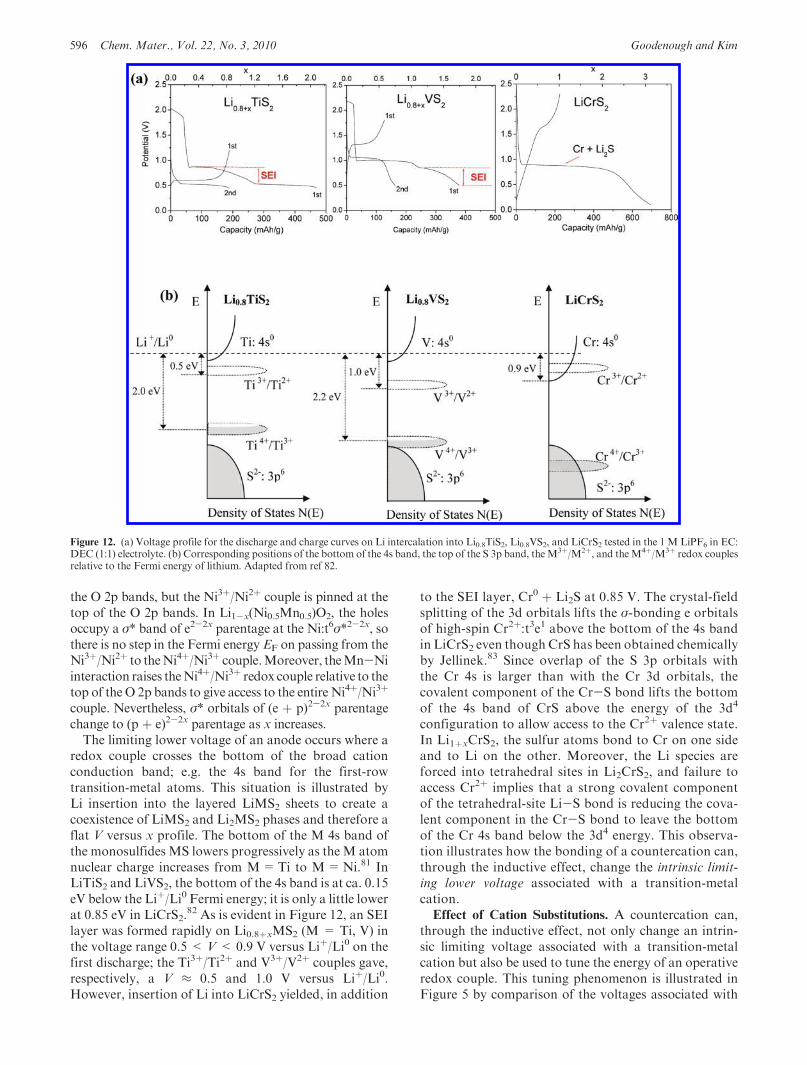
redox couple crosses the bottom of the broad cationconduction band; e.g. the 4s band for the first-rowtransition-metal atoms. This situation is illustrated byLi insertion into the layered LiMS2 sheets to create acoexistence of LiMS2 and Li2MS2 phases and therefore aflat V versus x profile. The bottom of the M 4s band ofthe monosulfides MS lowers progressively as theM atomnuclear charge increases from M=Ti to M=Ni.81 InLiTiS2 and LiVS2, the bottom of the 4s band is at ca. 0.15eV below the Liþ/Li0 Fermi energy; it is only a little lowerat 0.85 eV in LiCrS2.
82 As is evident in Figure 12, an SEIlayer was formed rapidly on Li0.8þxMS2 (M = Ti, V) inthe voltage range 0.5 < V< 0.9 V versus Liþ/Li0 on thefirst discharge; the Ti3þ/Ti2þ and V3þ/V2þ couples gave,respectively, a V ≈ 0.5 and 1.0 V versus Liþ/Li0.However, insertion of Li into LiCrS2 yielded, in addition
to the SEI layer, Cr0 þ Li2S at 0.85 V. The crystal-fieldsplitting of the 3d orbitals lifts the σ-bonding e orbitalsof high-spin Cr2þ:t3e1 above the bottom of the 4s bandin LiCrS2 even though CrS has been obtained chemicallyby Jellinek.83 Since overlap of the S 3p orbitals withthe Cr 4s is larger than with the Cr 3d orbitals, thecovalent component of the Cr-S bond lifts the bottomof the 4s band of CrS above the energy of the 3d4
configuration to allow access to the Cr2þ valence state.In Li1þxCrS2, the sulfur atoms bond to Cr on one sideand to Li on the other. Moreover, the Li species areforced into tetrahedral sites in Li2CrS2, and failure toaccess Cr2þ implies that a strong covalent componentof the tetrahedral-site Li-S bond is reducing the cova-lent component in the Cr-S bond to leave the bottomof the Cr 4s band below the 3d4 energy. This observa-tion illustrates how the bonding of a countercation can,through the inductive effect, change the intrinsic limit-ing lower voltage associated with a transition-metalcation.Effect of Cation Substitutions. A countercation can,
through the inductive effect, not only change an intrin-sic limiting voltage associated with a transition-metalcation but also be used to tune the energy of an operativeredox couple. This tuning phenomenon is illustrated inFigure 5 by comparison of the voltages associated with
Figure 12. (a) Voltage profile for the discharge and charge curves on Li intercalation into Li0.8TiS2, Li0.8VS2, and LiCrS2 tested in the 1 M LiPF6 in EC:DEC (1:1) electrolyte. (b) Corresponding positions of the bottom of the 4s band, the top of the S 3p band, theM3þ/M2þ, and theM4þ/M3þ redox couplesrelative to the Fermi energy of lithium. Adapted from ref 82.
Review Chem. Mater., Vol. 22, No. 3, 2010 597
the Ti4þ/Ti3þ couples in the NASICON framework ofLi1þxTi2(PO4)3 and the spinel Li4Ti5O12. A change from2.5 to 1.5 V shows that the countercation can have aprofound effect on a redox energy through the inductiveeffect. Moreover, comparison of the Ni4þ/Ni3þ redoxenergy in layered LiNiO2 where incomplete access isfound at 3.8 V with that in the spinel Li1-x[Ni0.5Mn1.5]O4
where complete access is found at 4.75 V, see Figure 13a,shows that covalent bonding with the countercation canalso increase the intrinsic limiting voltage of a cathode bylowering the top of theO 2p bands.We now inquire aboutthe effect of cation substitution for the active cation onthe intrinsic limiting voltage where the parent-cationredox energy is pinned at the top of an anion p band.For this purpose, we compare the influence of Mn4þ
versus Ti4þ substitutions on the energies of the Ni3þ/Ni2þ and Ni4þ/Ni3þ couples in layered and spinel oxides.Comparison with the influence of Cr3þ substitutions forvanadium in the layered LiV1-yCryS2 sulfides is also in-structive.Removal of Li from the tetrahedral sites of the spinel
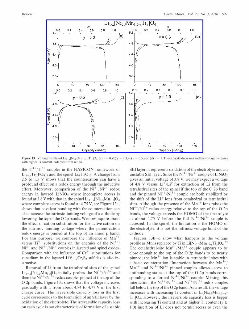
Li1-x[Ni0.5Mn1.5]O4 initially probes the Ni3þ/Ni2þ andthen the Ni4þ/Ni3þ redox couples pinned at the top of theO 2p bands. Figure 13a shows that the voltage increasesgradually with x from about 4.74 to 4.77 V in the firstcharge curve. The irreversible capacity loss in the firstcycle corresponds to the formation of an SEI layer by theoxidation of the electrolyte. The irreversible capacity losson each cycle is not characteristic of formation of a stable
SEI layer; it represents oxidation of the electrolyte and anunstable SEI layer. Since the Ni4þ/Ni3þ couple of LiNiO2
gives an initial voltage of 3.8 V, we may expect a voltageof 4.8 V versus Liþ/Li0 for extraction of Li from thetetrahedral sites of the spinel if the top of the O 2p bandand the pinned Ni4þ/Ni3þ couple are both stabilized bythe shift of the Liþ ions from octahedral to tetrahedralsites. Although the presence of the Mn4þ ions raises theNi4þ/Ni3þ redox energy relative to the top of the O 2pbands, the voltage exceeds the HOMO of the electrolyteat about 4.75 V before the full Ni4þ/Ni3þ couple isaccessed. In the spinel, the limitation is the HOMO ofthe electrolyte; it is not the intrinsic voltage limit of thecathode.Figures 13b-d show what happens to the voltage
profile asMn is replaced by Ti in Li[Ni0.5Mn1.5-yTiy]O4.84
The octahedral-site Mn5þ/Mn4þ couple appears to beclose enough to the top of the O 2p bands to be nearlypinned; the Mn5þ ion is stable in tetrahedral sites witha basic countercation. Interaction between the Mn5þ/Mn4þ and Ni4þ/Ni3þ pinned couples allows access toantibonding states at the top of the O 2p bands corre-sponding to a formal Ni4þ/Ni3þ couple. Missing thisinteraction, the Ni4þ/Ni3þ and Ni3þ/Ni2þ redox couplesfall below the top of theO 2pband.As a result, the voltageincreases with increasing Ti content in Li[Ni0.5Mn1.5-y-Tiy]O4. However, the irreversible capacity loss is biggerwith increasing Ti content and at higher Ti content (y g1.0) insertion of Li does not permit access to even the
Figure 13. Voltage profiles of Li1-x[Ni0.5Mn1.5-yTiy]O4: (a) y=0, (b) y=0.3, (c) y=0.5, and (d) y=1.The capacity decreases and the voltage increaseswith higher Ti content. Adapted from ref 84.
598 Chem. Mater., Vol. 22, No. 3, 2010 Goodenough and Kim
Ni3þ/Ni2þ redox couple; there appears a large irrever-sible curve at 4.9 V at y= 1.0. This is due to the fact thatthe two nickel redox couples fall further below the topof the O 2p bands with increasing Ti content in Li[Ni0.5-Mn1.5-yTiy]O4. Hence, the irreversible flat curve at 4.9 Vcorresponds to the irreversible access to the top of the O 2pbands, which indicates the intrinsic voltage limit of the spineloxides. However, this can be confused with the oxidationpotential of the electrolytes; it is estimated around 4.75 V.Figure 14 compares the voltage profiles of the layered
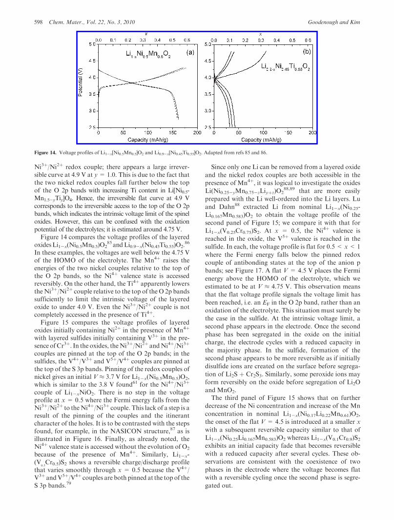
oxidesLi1-x(Ni0.5Mn0.5)O285 andLi0.9-x(Ni0.45Ti0.55)O2.
86
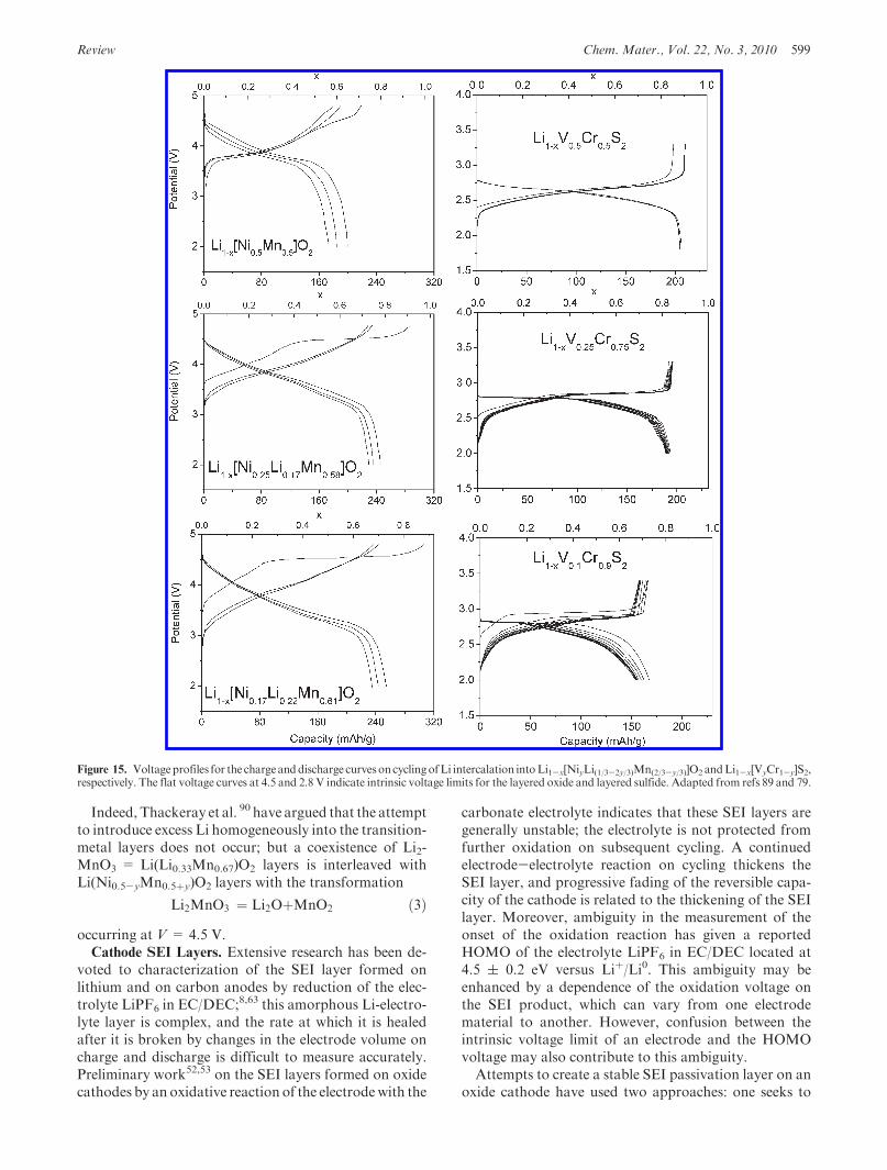
In these examples, the voltages are well below the 4.75 Vof the HOMO of the electrolyte. The Mn4þ raises theenergies of the two nickel couples relative to the top ofthe O 2p bands, so the Ni4þ valence state is accessedreversibly. On the other hand, the Ti4þ apparently lowersthe Ni3þ/Ni2þ couple relative to the top of the O 2p bandssufficiently to limit the intrinsic voltage of the layeredoxide to under 4.0 V. Even the Ni3þ/Ni2þ couple is notcompletely accessed in the presence of Ti4þ.Figure 15 compares the voltage profiles of layered
oxides initially containing Ni2þ in the presence of Mn4þ
with layered sulfides initially containing V3þ in the pre-sence ofCr3þ. In the oxides, theNi3þ/Ni2þ andNi4þ/Ni3þ
couples are pinned at the top of the O 2p bands; in thesulfides, the V4þ/V3þ and V5þ/V4þ couples are pinned atthe top of the S 3p bands. Pinning of the redox couples ofnickel gives an initial V ≈ 3.7 V for Li1-x(Ni0.5Mn0.5)O2,which is similar to the 3.8 V found61 for the Ni4þ/Ni3þ
couple of Li1-xNiO2. There is no step in the voltageprofile at x = 0.5 where the Fermi energy falls from theNi3þ/Ni2þ to theNi4þ/Ni3þ couple. This lack of a step is aresult of the pinning of the couples and the itinerantcharacter of the holes. It is to be contrasted with the stepsfound, for example, in the NASICON structure,87 as isillustrated in Figure 16. Finally, as already noted, theNi4þ valence state is accessed without the evolution of O2
because of the presence of Mn4þ. Similarly, Li1-x-(V
0.5Cr0.5)S2 shows a reversible charge/discharge profile
that varies smoothly through x = 0.5 because the V4þ/V3þ andV5þ/V4þ couples are both pinned at the top of theS 3p bands.79
Since only one Li can be removed from a layered oxide
and the nickel redox couples are both accessible in the
presence of Mn4þ, it was logical to investigate the oxides
Li(Ni0.25-yMn0.75-zLiyþz)O288,89 that are more easily
prepared with the Li well-ordered into the Li layers. Lu
and Dahn88 extracted Li from nominal Li1-x(Ni0.25-
Li0.167Mn0.583)O2 to obtain the voltage profile of the
second panel of Figure 15; we compare it with that for
Li1-x(V0.25Cr0.75)S2. At x = 0.5, the Ni4þ valence is
reached in the oxide, the V5þ valence is reached in the
sulfide. In each, the voltage profile is flat for 0.5 < x<1
where the Fermi energy falls below the pinned redox
couple of antibonding states at the top of the anion p
bands; see Figure 17. A flat V = 4.5 V places the Fermi
energy above the HOMO of the electrolyte, which we
estimated to be at V ≈ 4.75 V. This observation means
that the flat voltage profile signals the voltage limit has
been reached, i.e. an EF in the O 2p band, rather than an
oxidation of the electrolyte. This situation must surely be
the case in the sulfide. At the intrinsic voltage limit, a
second phase appears in the electrode. Once the second
phase has been segregated in the oxide on the initial
charge, the electrode cycles with a reduced capacity in
the majority phase. In the sulfide, formation of the
second phase appears to be more reversible as if initially
disulfide ions are created on the surface before segrega-
tion of Li2S þ Cr2S3. Similarly, some peroxide ions may
form reversibly on the oxide before segregation of Li2O
and MnO2.The third panel of Figure 15 shows that on further
decrease of the Ni concentration and increase of the Mn
concentration in nominal Li1-x(Ni0.17Li0.22Mn0.61)O2,
the onset of the flat V = 4.5 is introduced at a smaller x
with a subsequent reversible capacity similar to that of
Li1-x(Ni0.25Li0.167Mn0.583)O2 whereas Li1-x(V0.1Cr0.9)S2exhibits an initial capacity fade that becomes reversible
with a reduced capacity after several cycles. These ob-
servations are consistent with the coexistence of two
phases in the electrode where the voltage becomes flat
with a reversible cycling once the second phase is segre-
gated out.
Figure 14. Voltage profiles of Li1-x[Ni0.5Mn0.5]O2 and Li0.9-x[Ni0.45Ti0.55]O2. Adapted from refs 85 and 86.
Review Chem. Mater., Vol. 22, No. 3, 2010 599
Indeed, Thackeray et al. 90 have argued that the attemptto introduce excess Li homogeneously into the transition-metal layers does not occur; but a coexistence of Li2-MnO3 = Li(Li0.33Mn0.67)O2 layers is interleaved withLi(Ni0.5-yMn0.5þy)O2 layers with the transformation
Li2MnO3 ¼ Li2OþMnO2 ð3Þoccurring at V = 4.5 V.Cathode SEI Layers. Extensive research has been de-
voted to characterization of the SEI layer formed onlithium and on carbon anodes by reduction of the elec-trolyte LiPF6 in EC/DEC;8,63 this amorphous Li-electro-lyte layer is complex, and the rate at which it is healedafter it is broken by changes in the electrode volume oncharge and discharge is difficult to measure accurately.Preliminary work52,53 on the SEI layers formed on oxidecathodes by an oxidative reaction of the electrodewith the
carbonate electrolyte indicates that these SEI layers aregenerally unstable; the electrolyte is not protected fromfurther oxidation on subsequent cycling. A continuedelectrode-electrolyte reaction on cycling thickens theSEI layer, and progressive fading of the reversible capa-city of the cathode is related to the thickening of the SEIlayer. Moreover, ambiguity in the measurement of theonset of the oxidation reaction has given a reportedHOMO of the electrolyte LiPF6 in EC/DEC located at4.5 ( 0.2 eV versus Liþ/Li0. This ambiguity may beenhanced by a dependence of the oxidation voltage onthe SEI product, which can vary from one electrodematerial to another. However, confusion between theintrinsic voltage limit of an electrode and the HOMOvoltage may also contribute to this ambiguity.Attempts to create a stable SEI passivation layer on an
oxide cathode have used two approaches: one seeks to
Figure 15. Voltageprofiles for the charge anddischarge curvesoncyclingofLi intercalation intoLi1-x[NiyLi(1/3-2y/3)Mn(2/3-y/3)]O2 andLi1-x[VyCr1-y]S2,respectively. The flat voltage curves at 4.5 and 2.8 V indicate intrinsic voltage limits for the layered oxide and layered sulfide. Adapted from refs 89 and 79.
600 Chem. Mater., Vol. 22, No. 3, 2010 Goodenough and Kim
identify an additive91 to the electrolyte such as the ECcomponent for the carbon anode; the other attempts tocoat the cathode particles with a main-group oxide that ispermeable to Liþ ions.92 The former approach forms theSEI layer in situ after the electrode particles have madecontact with the carbon of the particle/carbon compositeelectrode, so the SEI layer formed does not interfere withelectronic contact between particles and the current col-lector. The second approach has obtained some improve-ment in cyclability, but complete coverage of the activeparticles with a passivation layer before fabricating theparticle/carbon composite electrode would seem to in-hibit electronic contact with the current collector. How tocoat the cathode/electrolyte interface with a stable SEIlayer while retaining electronic contact with the current
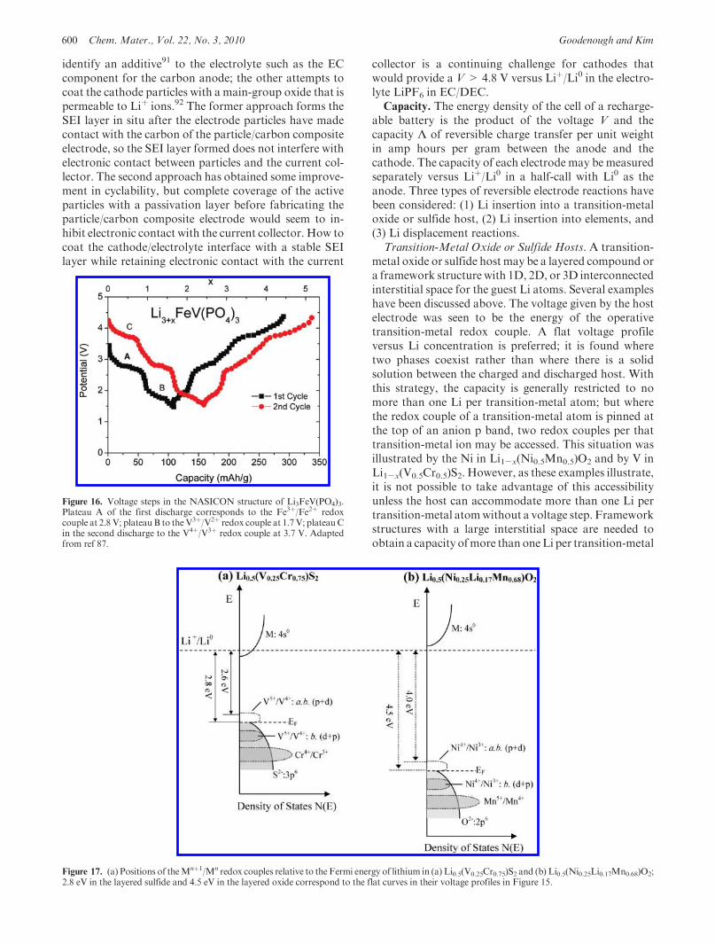
collector is a continuing challenge for cathodes thatwould provide a V> 4.8 V versus Liþ/Li0 in the electro-lyte LiPF6 in EC/DEC.Capacity. The energy density of the cell of a recharge-
able battery is the product of the voltage V and thecapacity Λ of reversible charge transfer per unit weightin amp hours per gram between the anode and thecathode. The capacity of each electrode may be measuredseparately versus Liþ/Li0 in a half-call with Li0 as theanode. Three types of reversible electrode reactions havebeen considered: (1) Li insertion into a transition-metaloxide or sulfide host, (2) Li insertion into elements, and(3) Li displacement reactions.
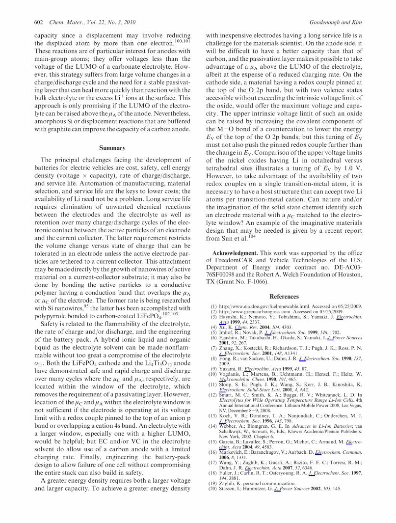
Transition-Metal Oxide or Sulfide Hosts. A transition-metal oxide or sulfide host may be a layered compound ora framework structure with 1D, 2D, or 3D interconnectedinterstitial space for the guest Li atoms. Several exampleshave been discussed above. The voltage given by the hostelectrode was seen to be the energy of the operativetransition-metal redox couple. A flat voltage profileversus Li concentration is preferred; it is found wheretwo phases coexist rather than where there is a solidsolution between the charged and discharged host. Withthis strategy, the capacity is generally restricted to nomore than one Li per transition-metal atom; but wherethe redox couple of a transition-metal atom is pinned atthe top of an anion p band, two redox couples per thattransition-metal ion may be accessed. This situation wasillustrated by the Ni in Li1-x(Ni0.5Mn0.5)O2 and by V inLi1-x(V0.5Cr0.5)S2. However, as these examples illustrate,it is not possible to take advantage of this accessibilityunless the host can accommodate more than one Li pertransition-metal atomwithout a voltage step. Frameworkstructures with a large interstitial space are needed toobtain a capacity ofmore than oneLi per transition-metal
Figure 16. Voltage steps in the NASICON structure of Li3FeV(PO4)3.Plateau A of the first discharge corresponds to the Fe3þ/Fe2þ redoxcouple at 2.8 V; plateauB to theV3þ/V2þ redox couple at 1.7V; plateauCin the second discharge to the V4þ/V3þ redox couple at 3.7 V. Adaptedfrom ref 87.
Figure 17. (a) Positions of theMnþ1/Mn redox couples relative to the Fermi energy of lithium in (a) Li0.5(V0.25Cr0.75)S2 and (b) Li0.5(Ni0.25Li0.17Mn0.68)O2;2.8 eV in the layered sulfide and 4.5 eV in the layered oxide correspond to the flat curves in their voltage profiles in Figure 15.
Review Chem. Mater., Vol. 22, No. 3, 2010 601
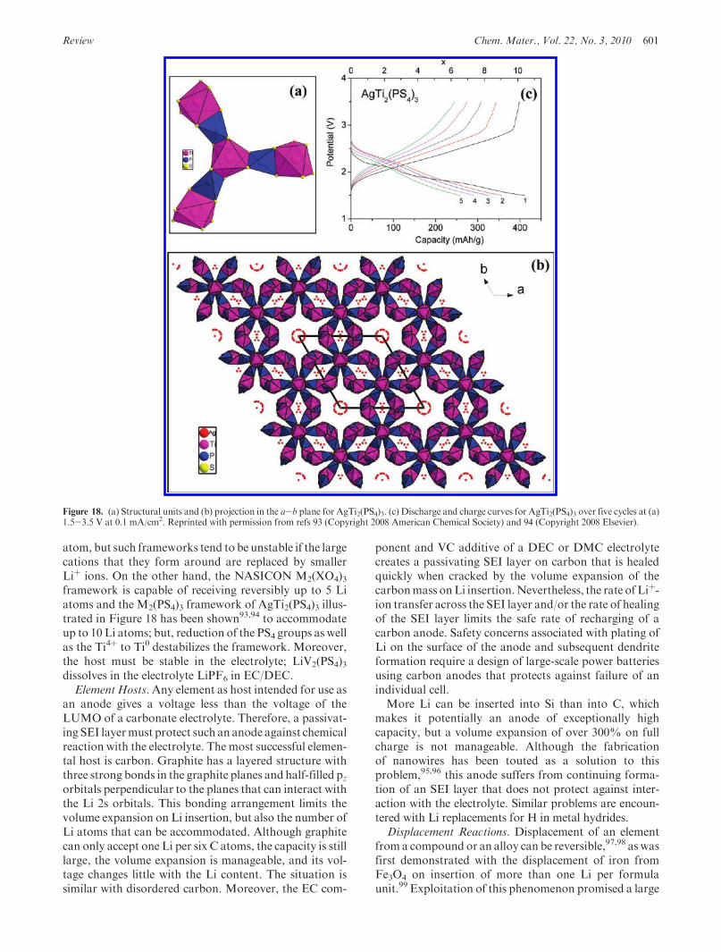
atom, but such frameworks tend to be unstable if the largecations that they form around are replaced by smallerLiþ ions. On the other hand, the NASICON M2(XO4)3framework is capable of receiving reversibly up to 5 Liatoms and the M2(PS4)3 framework of AgTi2(PS4)3 illus-trated in Figure 18 has been shown93,94 to accommodateup to 10 Li atoms; but, reduction of the PS4 groups as wellas the Ti4þ to Ti0 destabilizes the framework. Moreover,the host must be stable in the electrolyte; LiV2(PS4)3dissolves in the electrolyte LiPF6 in EC/DEC.
Element Hosts.Any element as host intended for use asan anode gives a voltage less than the voltage of theLUMO of a carbonate electrolyte. Therefore, a passivat-ing SEI layermust protect such an anode against chemicalreaction with the electrolyte. The most successful elemen-tal host is carbon. Graphite has a layered structure withthree strong bonds in the graphite planes and half-filled pzorbitals perpendicular to the planes that can interact withthe Li 2s orbitals. This bonding arrangement limits thevolume expansion on Li insertion, but also the number ofLi atoms that can be accommodated. Although graphitecan only accept one Li per six C atoms, the capacity is stilllarge, the volume expansion is manageable, and its vol-tage changes little with the Li content. The situation issimilar with disordered carbon. Moreover, the EC com-
ponent and VC additive of a DEC or DMC electrolytecreates a passivating SEI layer on carbon that is healedquickly when cracked by the volume expansion of thecarbonmass onLi insertion.Nevertheless, the rate of Liþ-ion transfer across the SEI layer and/or the rate of healingof the SEI layer limits the safe rate of recharging of acarbon anode. Safety concerns associated with plating ofLi on the surface of the anode and subsequent dendriteformation require a design of large-scale power batteriesusing carbon anodes that protects against failure of anindividual cell.More Li can be inserted into Si than into C, which
makes it potentially an anode of exceptionally highcapacity, but a volume expansion of over 300% on fullcharge is not manageable. Although the fabricationof nanowires has been touted as a solution to thisproblem,95,96 this anode suffers from continuing forma-tion of an SEI layer that does not protect against inter-action with the electrolyte. Similar problems are encoun-tered with Li replacements for H in metal hydrides.
Displacement Reactions. Displacement of an elementfrom a compound or an alloy can be reversible,97,98 as wasfirst demonstrated with the displacement of iron fromFe3O4 on insertion of more than one Li per formulaunit.99 Exploitation of this phenomenon promised a large
Figure 18. (a) Structural units and (b) projection in the a-b plane for AgTi2(PS4)3. (c) Discharge and charge curves for AgTi2(PS4)3 over five cycles at (a)1.5-3.5 V at 0.1 mA/cm2. Reprinted with permission from refs 93 (Copyright 2008 American Chemical Society) and 94 (Copyright 2008 Elsevier).
602 Chem. Mater., Vol. 22, No. 3, 2010 Goodenough and Kim
capacity since a displacement may involve reducingthe displaced atom by more than one electron.100,101
These reactions are of particular interest for anodes withmain-group atoms; they offer voltages less than thevoltage of the LUMO of a carbonate electrolyte. How-ever, this strategy suffers from large volume changes in acharge/discharge cycle and the need for a stable passivat-ing layer that can healmore quickly than reactionwith thebulk electrolyte or the excess Liþ ions at the surface. Thisapproach is only promising if the LUMO of the electro-lyte can be raised above the μAof the anode.Nevertheless,amorphous Si or displacement reactions that are bufferedwith graphite can improve the capacity of a carbon anode.
Summary
The principal challenges facing the development ofbatteries for electric vehicles are cost, safety, cell energydensity (voltage � capacity), rate of charge/discharge,and service life. Automation of manufacturing, materialselection, and service life are the keys to lower costs; theavailability of Li need not be a problem. Long service liferequires elimination of unwanted chemical reactionsbetween the electrodes and the electrolyte as well asretention over many charge/discharge cycles of the elec-tronic contact between the active particles of an electrodeand the current collector. The latter requirement restrictsthe volume change versus state of charge that can betolerated in an electrode unless the active electrode par-ticles are tethered to a current collector. This attachmentmay bemade directly by the growth of nanowires of activematerial on a current-collector substrate; it may also bedone by bonding the active particles to a conductivepolymer having a conduction band that overlaps the μAor μC of the electrode. The former rate is being researchedwith Si nanowires,95 the latter has been accomplished withpolypyrrole bonded to carbon-coated LiFePO4.
102,103
Safety is related to the flammability of the electrolyte,the rate of charge and/or discharge, and the engineeringof the battery pack. A hybrid ionic liquid and organicliquid as the electrolyte solvent can be made nonflam-mable without too great a compromise of the electrolyteσLi. Both the LiFePO4 cathode and the Li4Ti5O12 anodehave demonstrated safe and rapid charge and dischargeover many cycles where the μC and μA, respectively, arelocated within the window of the electrolyte, whichremoves the requirement of a passivating layer. However,location of the μC and μA within the electrolyte window isnot sufficient if the electrode is operating at its voltagelimit with a redox couple pinned to the top of an anion pband or overlapping a cation 4s band. An electrolyte witha larger window, especially one with a higher LUMO,would be helpful; but EC and/or VC in the electrolytesolvent do allow use of a carbon anode with a limitedcharging rate. Finally, engineering the battery-packdesign to allow failure of one cell without compromisingthe entire stack can also build in safety.A greater energy density requires both a larger voltage
and larger capacity. To achieve a greater energy density
with inexpensive electrodes having a long service life is achallenge for the materials scientist. On the anode side, itwill be difficult to have a better capacity than that ofcarbon, and the passivation layermakes it possible to takeadvantage of a μA above the LUMO of the electrolyte,albeit at the expense of a reduced charging rate. On thecathode side, a material having a redox couple pinned atthe top of the O 2p band, but with two valence statesaccessible without exceeding the intrinsic voltage limit ofthe oxide, would offer the maximum voltage and capa-city. The upper intrinsic voltage limit of such an oxidecan be raised by increasing the covalent component ofthe M-O bond of a countercation to lower the energyEV of the top of the O 2p bands; but this tuning of EV
must not also push the pinned redox couple further thanthe change inEV. Comparison of the upper voltage limitsof the nickel oxides having Li in octahedral versustetrahedral sites illustrates a tuning of EV by 1.0 V.However, to take advantage of the availability of tworedox couples on a single transition-metal atom, it isnecessary to have a host structure that can accept two Liatoms per transition-metal cation. Can nature and/orthe imagination of the solid state chemist identify suchan electrode material with a μC matched to the electro-lyte window? An example of the imaginative materialsdesign that may be needed is given by a recent reportfrom Sun et al.104
Acknowledgment. This work was supported by the officeof FreedomCAR and Vehicle Technologies of the U.S.Department of Energy under contract no. DE-AC03-76SF00098 and the Robert A.Welch Foundation of Houston,TX (Grant No. F-1066).
References
(1) http://www.eia.doe.gov/fuelrenewable.html. Accessed on 05/25/2009.(2) http://www.greencarbongress.com. Accessed on 05/25/2009.(3) Hayashi, K.; Nemoto, Y.; Tobishima, S.; Yamaki, J. Electrochim.
Acta 1999, 44, 2337.(4) Xu, K. Chem. Rev. 2004, 104, 4303.(5) Imhof, R.; Novak, P. J. Electrochem. Soc. 1999, 146, 1702.(6) Egashira, M.; Takahashi, H.; Okada, S.; Yamaki, J. J. Power Sources
2001, 92, 267.(7) Zhang, X.; Kostecki, R.; Richardson, T. J.; Pugh, J. K.; Ross, P. N.
J. Electrochem. Soc. 2001, 148, A1341.(8) Fong, R.; van Sacken, U.; Dahn, J. R. J. Electrochem. Soc. 1990, 137,
2009.(9) Yazami, R. Electrochim. Acta 1999, 45, 87.
(10) Vogdanis, L.; Martens, B.; Uchtmann, H.; Hensel, F.; Heitz, W.Makromolekul. Chem. 1990, 191, 465.
(11) Sloop, S. E.; Pugh, J. K.; Wang, S.; Kerr, J. B.; Kinoshita, K.Electrochem. Solid-State Lett. 2001, 4, A42.
(12) Smart, M. C.; Smith, K. A.; Bugga, R. V.; Whitcanack, L. D. InElectrolytes for Wide Operating Temperature Range Li-Ion Cells. 4thAnnual International Conference: LithiumMobile Power 2008, Las Vegas,NV, December 8-9, 2008.
(13) Koch, V. R.; Dominey, L. A.; Nanjundiah, C.; Onderchen, M. J.J. Electrochem. Soc. 1996, 143, 798.
(14) Webber, A.; Blomgren, G. E. In Advances in Li-Ion Batteries; vanSchalkwijk, W., Scrosati, B., Eds.; Kluwer Academic/Plenum Publishers:New York, 2002; Chapter 6.
(15) Garcia, B.; Lavallee, S.; Perron, G.; Michot, C.; Armand, M. Electro-chim. Acta 2004, 49, 4583.
(16) Markevich, E.; Baranchugov, V.; Aurbach, D. Electrochem. Commun.2006, 8, 1331.
(17) Wang, Y.; Zaghib, K.; Guerfi, A.; Bazito, F. F. C.; Torresi, R. M.;Dahn, J. R. Electrochim. Acta 2007, 52, 6346.
(18) Fuller, J.; Carlin, R. T.; Osteryoung, R. A. J. Electrochem. Soc. 1997,144, 3881.
(19) Zaghib, K. personal communication.(20) Stassen, I.; Hambitzer, G. J. Power Sources 2002, 105, 145.
Review Chem. Mater., Vol. 22, No. 3, 2010 603
(21) Zinck, L.; Borck, M.; Ripp, C.; Hambitzer, G. J. Appl. Electrochem.2006, 36, 1291.
(22) Wright, P. V. Brit. Polym. J. 1975, 7, 319.(23) Armand, M. B.; Chagbano, J. M.; Duclot, M. J. In Fast Ion Transport
in Solid; Vashishta, P., Mundy, J. N., Shenoy, G. K., Eds.; Elsevier NHolland: New York, 1979; p131.
(24) Nishimoto, A.;Watanabe,M.; Ikeda, Y.; Kojiya, S.Electrochim. Acta1998, 43, 1177.
(25) Croce, F.; Appetecchi, G. B.; Persi, L.; Scrosati, B.Nature 1998, 394, 456.(26) Croce, F.; Curini, R.; Martinelli, A.; Persi, L.; Ronci, F.; Scrosati, B.
J. Phys. Chem. B 1999, 103, 10632.(27) Croce, F.; Settimi, L.; Scrosati, B.Electrochem. Commun. 2006, 8, 364.(28) Pradel, A.; Ribes, M. Mater. Chem. Phys. 1989, 23, 121.(29) Adachi, G.; Imanaka, N.; Aono, H. Adv. Mater. 1996, 8, 127.(30) Minami, T.; Hayashi, A.; Tatsumisago, M. Solid State Ionics 2006,
177, 2715.(31) Kim, Y.; Saienga, J.; Martin, S.W. J. Phys. Chem. B 2006, 110, 16318.(32) Dudney, N. J. In Lithium Batteries; Nazri, G. A., Pistoia, G., Eds.;
Kluwer Academic Publishers: Norwell, MA, 2004; p 623.(33) Takada, K.; Aotani, N.; Kondo, S. J. Power Sources 1993, 43, 135.(34) Machida, N.; Maeda, H.; Peng, H.; Shigematsu, T. J. Electrochem.
Soc. 2002, 149, A688.(35) Nagata, K.; Nanno, T. J. Power Sources 2007, 174, 832.(36) Bates, J. B.; Dudney, N. J.; Neudecker, B.; Ueda, A.; Evans, C. K.
Solid State Ionics 2000, 135, 33.(37) Feuillade, G.; Perche, Ph. J. Appl. Electrochem. 1975, 5, 63.(38) Appetecchi, G. B.; Croce, F.; Marassi, R.; Persi, L.; Romagnoli, P.;
Scrosati, B. Electrochim. Acta 1999, 45, 23.(39) Persi, L.; Croce, F.; Scrosati, B. Electrochem. Commun. 2002, 4, 92.(40) Scrosati, B. In Advances in Li-Ion Batteries; van Schalkwijk, W.,
Scrosati, B., Eds.; Kluwer Academic/Plenum Publishers: New York,2002; Chapter 8.
(41) Fuller, J.; Breda, A. C.; Carlin, R. T. J. Electrochem. Soc. 1997, 144,L67.
(42) Shin, J.-H.; Henderson, W. A.; Passerini, S. Electrochem. Commun.2003, 5, 1016.
(43) Ye, H.; Huang, J.; Xu, J. J.; Khalfan, A.; Greenbaum, S. G.J. Electrochem. Soc. 2007, 154, A1048.
(44) Sirisopanaporn, C.; Fernicola, A.; Scrosati, B. J. Power Sources 2009,186, 490.
(45) Guerfi, A.; Dontigny,M.; Kobayashi, Y.; Vijh, A.; Zaghib, K. J. SolidState Electr. 2009, 13, 1003.
(46) Cho, J.; Liu, M. Electrochim. Acta 1997, 42, 1481.(47) Hayashi, A.; Kitade, T.; Ikeda, Y.; Kohjiya, S.; Matsuda, A.; Tatsumi-
sago, M.; Minami, T. Chem. Lett. 2001, 814.(48) Inda, Y.; Katoh, T.; Baba, M. J. Power Sources 2007, 174, 741.(49) Murphy, D. W.; Carides, J. N.; DiSalvo, F. J.; Cros, C.; Waszczak,
J. V. Mater. Res. Bull. 1977, 12, 825.(50) Kim,Y.;Goodenough, J. B.Electrochem. Solid-State Lett. 2009, 12, A73.(51) Blyr,A.; Sigala,C.;Amatucci,G.;Guyomard,D.;Chabre,Y.; Tarascon,
T. M. J. Electrochem. Soc. 1998, 145, 194.(52) Aurbach, D. J. Power Sources 2000, 89, 206.(53) Edstrom, K.; Gustafsson, T.; Thomas, J. O.Electrohim. Acta 2004, 50,
397.(54) Wang, Z.; Sun, Y.; Chen, L.; Huang,X. J. Electrochem. Soc. 2004, 151,
A914.(55) Padhi, A. K. Ph.D. Mapping Redox Energies of Electrode Materials
for LithiumBatteries. Thesis, TheUniversity of Texas at Austin, 1997.(56) Steele, B. C.H. InFast Ion Transport in Solids; vanGool,W., Ed.; North-
Holland: Amsterdam, 1973.(57) Wittingham, M. S. Science 1976, 192, 1126.(58) Mitzushima, K.; Jones, P. C.; Wiseman, P. J.; Goodenough, J. B.
Mater. Res. Bull. 1980, 15, 783.(59) Wittingham, M. S. In Fast Ion Transport in Solids; van Gool, W., Ed;
North-Holland: Amsterdam, 1973.(60) Dampier, F. W. J. Electrochem. Soc. 1974, 121, 656.(61) Goodenough, J. B.; Mizushima, K.; Takeda, T. Jpn. J. Appl. Phys.
1980, 19-3, 305.(62) Dey, A. N.; Sullivan, B. P. J. Electrochem. Soc. 1970, 117, 222.(63) Aurbach, D, In Advances in Li-Ion Batteries; van Schalkwijk, W.,
Scrosati, B., Eds.; Kluwer Academic/Plenum Publishers: New York,2002; Chapter 1.
(64) Nagaura, T.; Tozawa, K. Prog. Batteries Solar Cells 1990, 9, 209.
(65) Sinha, S.; Murphy, D. W. Solid State Ionics 1986, 20, 81.(66) Thackeray, M. M.; David, W. I. F.; Bruce, P. G.; Goodenough, J. B.
Mater. Res. Bull. 1983, 18, 461.(67) Thackeray, M. M.; Jahnson, P. J.; De Picciotto, L. A.; Bruce, P. G.;
Goodenough, J. B. Mater. Res. Bull. 1984, 19, 435.(68) Amatucci, G. G.; Pereira, N; Zheng, T.; Tarascon, J.-M. J. Electro-
chem. Soc. 2001, 148, A171.(69) Choi, W.; Manthiram, A. J. Electrochem. Soc. 2007, 154, A792.(70) Goodenough, J. B.; Hong, H.Y.-P.; Kafalas, J. A. Mater. Res. Bull.
1976, 11, 203.(71) Manthiram, A.; Goodenough, J. B. J. Solid State Chem. 1987, 71,
349.(72) Goodenough, J. B. Electrochem. Soc. Proc. 2000, 99-24, 1.(73) Goodenough, J. B. InAdvances in Li-Ion Batteries; van Schalkwijk, W.,
Scrosati, B., Eds.; Kluwer Academic/Plenum Publishers: New York, 2002;Chapter 4.
(74) Padhi, A. K.; Nanjundaswamy, K. S.; Goodenough, J. B. J. Electro-chem. Soc. 1997, 144, 1188.
(75) Johnston, D. C.; Prakash, H.; Zachariasen, W. H.; Viswanathan, R.Mater. Res. Bull. 1973, 8, 777.
(76) Edwards, P. P.; Egdell, R. G.; Fragala, I.; Goodenough, J. B.;Harrison, M. R.; Orchard, A. F.; Scott, E. G. J. Solid State Chem.1984, 54, 127.
(77) Harrison, M. R.; Edwards, P. P.; Goodenough, J. B. J. Solid StateChem. 1984, 54, 426.
(78) Ferg, E.; Gummow, R. J.; de Kock, A.; Thackeray, M. M. J. Electro-chem. Soc. 1994, 141, L147.
(79) Goodenough, J. B.; Kim, Y. J. Solid State Chem., in press.(80) Hert, J. T.; Huang, Q; McQueen, T.; Klimczuk, T.; Bos, J. W. G.;
Viciu, L.; Cava, R. J. Phys. Rev. B 2008, 77, 075119.(81) Kim, Y.; Goodenough, J. B. J. Phys. Chem. C 2008, 112, 15060.(82) Kim, Y.; Park, K. S.; Song, S. H.; Han, J. T.; Goodenough, J. B.
J. Electrochem. Soc. 2009, 156, A703.(83) Jellinek, F. Acta Crystallogr. 1957, 10, 620.(84) Kim, J.-H.; Myung, S.-T.; Yoon, C. S.; Oh, I.-H.; Sun, Y.-K.
J. Electrochem. Soc. 2004, 151, A1911.(85) Schougaard, S. B.; Breger, J.; Jiang, M.; Grey, C. P.; Goodenough, J.
B. Adv. Mater. 2006, 18, 905.(86) Kang,K.; Carlier,D.; Reed, J.; Arroyo, E.M.;Ceder,G.; Croguennec,
L.; Delmas, C. Chem. Mater. 2003, 15, 4503.(87) Nanjundaswamy, K. S.; Padhi, A. K.; Goodenough, J. B.; Okada, S.;
Ohtsuka, H.; Arai, H.; Yamaki, J. Solid State Ionics 1996, 92, 1.(88) Lu, Z.; Dahn, J. R. J. Electrochem. Soc. 2002, 149, A815.(89) Park, Y. J.; Hong, Y. S.; Wu, X.W.; Ryu, K. S.; Chang, S. H. J. Power
Sources 2004, 129, 288.(90) Thackeray, M. M.; Kang, S. H.; Johnson, C. S.; Vaughey, J. T.;
Benedek, R.; Hackney, S. A. J. Mater. Chem. 2007, 17, 3112.(91) Abe, K.; Ushigoe, Y.; Yoshitake, H.; Yoshio, M. J. Power Sources
2006, 153, 328.(92) Liu, J.; Manthiram, A. Chem. Mater. 2009, 21, 1695.(93) Kim, Y.; Arumugam, N.; Goodenough, J. B. Chem. Mater. 2008, 20,
470.(94) Kim, Y.; Goodenough, J. B. Electrochem. Commun. 2008, 10, 497.(95) Chan, C. K.; Peng, H.; Liu, G.;Mcllwrath, K.; Zhang, X. F.; Huggins,
R.; Cui, Y. Nat. Nanotechnol. 2008, 3, 31.(96) Kim, H.; Cho, J. Nano Lett. 2008, 8, 3688.(97) Arico, A. S.; Bruce, P.; Scrosati, B.; Tarascon, J.-M.; Schalkwijk, W.
V. Nat. Mater. 2005, 4, 366.(98) Bruce, P. G.; Scrosati, B.; Tarascon, J.-M. Angew. Chem., Int. Ed.
2008, 47, 2930.(99) Thackeray, M. M.; David, W. I. F.; Goodenough, J. B. Mater. Res.
Bull. 1982, 17, 785.(100) Thackeray, M. M.; Vaughey, J. T.; Johnson, C. S.; Kropf, A. J.;
Tostmann, H.; Benedek, R.; Sarankonsri, T.; Hackney, S. A. Proc.-Electrochem. Soc. 2001, 2000-36, 92.
(101) Thackeray, M. M.; Vaughey, J. T.; Fransson, L. M. L. JOM 2002,54, 20.
(102) Park, K. S.; Schougaard, S. B.; Goodenough, J. B. Adv. Mater. 2007,19, 848.
(103) Huang, Y. H.; Park, K. S.; Goodenough, J. B. J. Electrochem. Soc.2006, 153, A2282.
(104) Sun, Y.-K.; Myung, S.-T.; Park, B.-C.; Prakash, J.; Belharouak, I.;Amine, K. Nat. Mater. 2009, 8, 320.