chalet 1800chalet 1800 wood burning stove · chalet 1800chalet 1800 wood burning stove ... rating...
TRANSCRIPT
200-0224 SEPT 2013
Users’ Installation
Operation and
Maintenance Manual
7116 Beatty Dr Mission, BC V2V 6B4 Canada
CHALET 1800CHALET 1800
Wood Burning
Stove
Installer: Please complete the details on the back cover and leave this manual with the homeowner.
Homeowner: Please keep these instructions for future reference.
PRIOR TO FIRST FIRE: Remove all labels from glass. Clean fingerprints from plated surfaces with a glass cleanser and soft cloth to prevent permanent staining.
CHILDREN AND ADULTS SHOULD BE ALERTED TO THE HAZARDS OF HIGH SURFACE
TEMPERATURES, ESPECIALLY THE STOVE GLASS, AND SHOULD STAY AWAY TO AVOID BURNS OR CLOTHING IGNITION. THIS UNIT CONTAINS SMALL PARTS DURING ASSEMBLY THAT SHOULD
BE KEPT AWAY FROM CHILDREN DUE TO CHOCKING HAZARD WHICH COULD RESULT IN PER-
SONAL INJURY OR DEATH.


Chalet 1800 3
Congratulations on choosing a state-of-the-art Archgard Hearth Product!
The hand crafted Chalet 1800 has been designed to provide you with comfort, security and economy for many years of trouble-free enjoyment.
It has been our experience that the overall enjoyment of your new appliance will be greatly enhanced by becoming familiar with its installation, operation and maintenance. Prior to installation, we ask that you take a few moments to read this manual.
We wish you and your family many years of enjoyment in the warmth and comfort of this hearth appliance.
Thank you for choosing Archgard Industries!
CHALET 1800
Legs & Bottom Shield
Ash Drawer & Lid
Ash Drawer & Lid
Pedestal
Optional Combustion Air
Chalet 1800 4
Important Safety Notes 5
Rating Plate Label 7
Clearances 8
Dimensions - Pedestal Unit 9
Dimensions - Leg Unit 10
Specifications 11
Pedestal Assembly Instructions 12
Leg Assembly Instructions 13
Door Assembly Instructions 14
INSTALLATION METHODS
Door Installation 15
Air Tube Installation 16
Mobile Home Installation - Listed Components 17
Blower / Fan Installation 18
Residential Installation 19
Mobile Home Installation 21
Chase Enclosure / Masonry Chimney 22
Recommended Minimum Chimney Heights 24
Vent Specifications / First Fire 25
MAINTENANCE
Troubleshooting 26
Creosote & Chimney Fires 28
In Case of a Chimney Fire / Chimney Maintenance / Wood 29
Door Gasket / Latch Adjustment / Glass 31
Glass Maintenance 32
Ash Disposal 33
ACCESSORY / PARTS REPLACEMENT
Exploded view of Chalet 1800 - Parts 34
Accessory & Replacement Parts List 35
Archgard Warranty 36
Warranty Registration Card 37
Notes 40
Installation Information 41
TABLE OF CONTENTS
Chalet 1800 5
IMPORTANT SAFETY NOTES
1. When installing your stove, particular attention should be paid to fire protection. If this room heater is not properly installed, a house fire may result. To reduce the risk of fire, follow the installation instructions. Con-tact local building, fire officials or authority having jurisdiction about restrictions, installation inspection and permit requirements in your area.
2. CAUTION: Never use gasoline, gasoline-type lantern fuel, kerosene, charcoal lighter fluid, or similar liquids to start or “freshen up” a fire in this heater. Keep all such liquids well away from the heater while it is in use.
3. DO NOT BURN GARBAGE OR FLAMMABLE FLUIDS SUCH AS GASOLINE, NAPHTHA OR ENGINE OIL. Do not burn treated wood, or wood with salt (driftwood, etc.). Burning materials other than wood (including charcoal) under adverse conditions may generate carbon monoxide in the home, resulting in illness or possi-ble death.
4. Do not store any fuel closer than 2 feet from your unit. Do not place wood, paper, furniture, drapes or other combustibles near the appliance.
5. During operation, if any part of the stove starts to glow, the stove is in an over-fired condition. Close the air control completely by pushing it in until the glowing has stopped. OVERFIRING VOIDS YOUR WARRANTY!
6. RISK OF FIRE! Do not operate with stove door or ash removal system door open.
7. Your woodstove should burn dry, standard firewood only. The use of cut lumber, plywood, “mill ends”, etc. is not recommended as this fuel can easily overheat your woodstove. Salt water driftwood and chemically treated fire logs also must not be burned in your woodstove.
8. WARNING! Never draw outside combustion air from a wall, floor or ceiling cavity or from any
enclosed space such as an attic or garage, carport or under a mobile home.
9. Check your chimney system thoroughly when installing into an existing metal or masonry chimney. Seek professional advice if in doubt about its condition.
10. Comply with all minimum clearances to combustibles as shown in this manual for this appliance.
11. Build fire on brick firebox floor. Do not use grates, andirons or other methods to support fuel.
12. HOT WHILE IN OPERATION! Keep children, pets, clothing and furniture away. Contact can cause skin burns.
13. Do not operate without fully assembling all components. Burning your stove without the legs attached (if supplied with unit) will void your warranty, and could present a serious safety hazard.
14. All fuel burning appliances consume oxygen during operation. It is important that you supply a source of fresh air to your unit while burning. A slightly opened window is sufficient for this purpose. If you also have a fireplace in your home, a downdraft may be created causing a draft down your chimney. Provide adequate ventilation.
15. The controls of your unit or the air supply passages should not be altered to increase firing for any reason.
16. If you burn the unit too slowly or at too low a setting your unit will not be operating as efficiently as it can. An easy rule of thumb says that if your glass is clean, then your flue is clean and your exhaust is clean. Burn the stove hot enough to keep your glass clean and you won't need to clean your flue as often.
17. Burning wet or green, unseasoned wood, could cause excessive creosote accumulation in the flue pipe and chimney. This could result in a chimney fire. Store wood in a dry location.
18. Do not permit creosote or soot build-up in the chimney system. Check and clean chimney at regular inter-vals. Failure to do so can result in a serious chimney fire.
19. Cool ashes should be disposed of carefully, using a metal container.
20. Do not connect to any air distribution duct or system.
21. Do not connect this unit to a chimney flue already serving another appliance.
22. This appliance must be connected to a vent and terminate to the outside of the building envelope. Never vent to another room or inside a building.
23. Do not operate if the gasket on the door or ash plug is missing or damaged.
24. Do not operate with broken glass.
25. For further information refer to NFPA 211 (USA) or CAN/CSA-B365 (Canada).
Chalet 1800 6
SAFETY NOTE: If this woodstove is not properly installed, a house fire may result. For your safety, follow the installation instructions, contact local building, fire officials, or au-thority having jurisdiction about restrictions and installation inspection requirements in your area. The authority having jurisdiction should be consulted before installation to determine the need to obtain a permit. WHEN LOCATING YOUR STOVE: Consider safety, convenience, traffic flow, and the fact that the stove will need a chimney and chimney connector. It is a good idea to plan your installation on paper, using exact measurements for clearances and floor protec-tion, before actually beginning the installation. These installation instructions describe the installation and operation of the CHALET 1800 woodstove. This stove meets the U.S. Environmental Protection Agency’s 1990 particulate emission standards. The Chalet 1800 is listed by Lab Test Laboratories, Inc. to UL Safety Standard 1482, ULC S627, and (UM) 84-HUD. The Chalet 1800 is approved for mobile home installations when not installed in a sleeping room and when an outside combustion air inlet is provided. The structural integrity of the mobile home floor, ceiling, and walls must be maintained. The stove must be properly grounded to the frame of the mobile home and use only listed double-wall connector pipe. The Mo-bile Home Outside Air Kit must be installed in a mobile home installation.
SAFETY LABEL A copy of the label that accompanies each Archgard Chalet 1800, is printed on the next page for your convenience. NOTE: Archgard units are constantly being improved. If there is a conflict between the label on the unit and the one printed here, the label on the unit is the correct one. The safety label is located on the back panel of the stove.
YOUNG CHILDREN SHOULD BE CAREFULLY SUPERVISED WHEN THEY ARE IN THE SAME ROOM AS THE APPLIANCE.

Chalet 1800 7
CAUTION HOT WHILE IN OPERATION - DO NOT TOUCH.
KEEP CHILDREN, CLOTHING AND FURNITURE AWAY. CONTACT MAY
CAUSE SKIN BURNS. READ NAMEPLATE AND INSTRUCTIONS.
LISTED SPACE HEATER, SOLID FUEL TYPE. ALSO SUITABLE FOR MOBILE HOME INSTALLATION.
MODEL: CHALET 1800 FREE STANDING STOVE TESTED TO: UL 1482-96 / ULC S627-00
SERIAL NUMBER / NUMÉRO DE SÉRIE:
DO NOT REMOVE THIS LABEL
BACKWALL
SID
EW
AL
L
A B E
D
BACKWALL
SID
EW
AL
L
G
H J
I
G
ADJACENT WALL
SID
EW
AL
L
F
C
PREVENT HOUSE FIRES:
INSTALL ONLY IN ACCORDANCE WITH THE MANUFACTURER’S INSTALLATION AND OPERATING INSTRUCTIONS. CONTACT LOCAL BUILD-ING OR FIRE OFFICIALS ABOUT RESTRICTIONS AND INSTALLATION INSPECTION IN YOUR AREA. USE 6 in (152 mm) DIAMETER MINIMUM 24 MSG BLACK OR MSG BLUED STEEL CONNECTOR WITH LISTED UL103 HT (IN USA) OR ULC S629 (IN CANADA) FACTORY BUILT CHIMNEY SUITIBLE FOR USE WITH SOLID FUELS OR MASONRY CHIMNEY. SEE LOCAL BUILDING CODE OR MANUFACTURER’S INSTRUCTIONS FOR PRECAUTIONS REQUIRED FOR PASSING A CHIMNEY THROUGH A COMBUSTIBLE WALL OR CEILING, DO NOT PASS CHIMNEY CONNECTOR THROUGH COMBUSTIBLE CEILING. DO NOT CONNECT THIS UNIT TO A CHIMNEY SERVING ANOTHER APPLIANCE.
MINIMUM CLEARANCES TO COMBUSTIBLE MATERIALS
MEASURE FROM HEATER FLUE CENTRE LINE
RESIDENTIAL INSTALLATION USING SINGLE WALL CONNECTOR
SIDEWALL A - 406 mm / 16” D - 711 mm / 28”
BACKWALL B - 406 mm / 16” E - 533 mm / 21”
CORNER C - 280 mm / 11” F - 585 mm / 23”
INSTALLATION USING LISTED DOUBLE WALL CONNECTOR - MOBILE HOME
SIDEWALL A - 406 mm / 16” D - 711 mm / 28”
BACKWALL B - 203 mm / 8” E - 311 mm / 12.25”
CORNER C - 280 mm / 11” F - 585 mm / 23”
INSTALLATION USING LISTED DOUBLE WALL CONNECTOR – RESIDENTIAL CLOSE CLEARANCE
SIDEWALL A - 406 mm / 16” D - 711 mm / 28”
BACKWALL B - 203 mm / 8” E - 311 mm / 12.25”
CORNER C - 280 mm / 11” F - 585 mm / 23”
INSTALLATION USING LISTED DOUBLE WALL CONNECTOR - ALCOVE
SIDEWALL G - 406 mm / 16” I - 711 mm / 28”
BACKWALL H - 203 mm / 8” J - 311 mm / 12.25”
MINIMUM ALCOVE CEILING HEIGHT : 2150 mm / 68”
MAXIMUM ALCOVE DEPTH : 915 mm / 36” (Minimum 38” clearance from stove top to ceiling)
8”
8” 8”
18”
FRONT
SID
E
SID
E
Canadian Installations
6” 6”
16”
FRONT
SID
E
SID
E
USA Installations
FLOOR PROTECTION
Any combustible flooring or floor covering beneath the appli-ance and / or within the area extending horizontally beyond the appliance on any side equipped with a door, and beyond the appliance on the other sides and rear, shall be protected by a continuous, durable, noncombustible pad that will provide ember protection. Refer to Canadian CSA B365 and USA NFPA 211 Installation Codes for details.
UNITED STATES ENVIROMENTAL PROTECTION AGENCY CERTIFIED TO COMPLY WITH JULY 1990 PARTICULATE EMISSION STANDARDS
For use with solid fuel only. Use of other fuels may damage the heater and create a hazardous condition. Do not obstruct combustion air opening. Operate only with firebricks in place. Risk of smoke and flame spillage, Operate only with doors fully closed. Open front door to feed fire only. Do not use grate or
elevated fire, build wood fire directly on hearth. DO NOT OVERFIRE - IF HEATER OR CHIMNEY CONNECTOR GLOWS YOU ARE OVER-
FIRING. Inspect and clean chimney connector frequently, under certain conditions of use creosote build-up may occur rapidly. Keep furnishings and other combustibles materials away from heater. Replace glass only with ceramic glass. Combustible floor may be protected by non-combustible material extend-
ing beneath the heater and to the front and sides as indicated or to the nearest permitted combustible material. Optional fan kit Part # FK-1800 electrical
rating 115 Volts 60 Hz 2 Amps. Danger risk of electrical shock, disconnect power before servicing unit. Components required for Mobile Home Installa-tion: Outside Air Kit and double wall connector with listed chimney system.
Manufactured by: ARCHGARD INDUSTRIES LTD.
MISSION, BC ~ CANADA Made in Canada
DE
C
NO
V
OC
T
SE
P
AU
G
JUL
JU
N
MA
Y
AP
R
MA
R
FE
B
JAN
2015
DA
TE
OF
MA
NF
AC
TU
RE
: 2014
2013
303-0142

Chalet 1800 8
RESIDENTIAL INSTALLATION USING SINGLE WALL CONNECTOR
SIDEWALL A 406 mm / 16” D 711 mm / 28” BACKWALL B 406 mm / 16” E 533 mm / 21” CORNER C 280 mm / 7” F 585 mm / 23”
INSTALLATION USING LISTED DOUBLE WALL CONNECTOR
MOBILE HOME, RESIDENTIAL CLOSE CLEARANCE
SIDEWALL A - 406 mm / 16” D - 711 mm / 28” BACKWALL B - 203 mm / 8” E - 311 mm / 12.25” CORNER C - 280 mm / 7” F - 585 mm / 23”
INSTALLATION USING LISTED DOUBLE WALL CONNECTOR - ALCOVE
SIDEWALL G - 406 mm / 16” I - 711 mm / 28” BACKWALL H - 203 mm / 8” J - 311 mm / 12.25” MAXIMUM ALCOVE DEPTH L - 915 mm / 36” FLOOR PAD US K - 1727 mm / 68” M - 1701 mm / 67” CANADA K - 1778 mm / 70” M - 1753 mm / 69”
MINIMUM ALCOVE CEILING HEIGHT : 2150 mm / 68” Minimum 38” clearance from stove top to ceiling The floor pad (ember pad) must be of non-combustible ma-terial and must extend 16" in front of the door opening and 6" to the sides and rear of the unit. In Canada, the floor pad (ember pad) must be of non-combustible material and must extend 18" (450mm) in front of the door opening and 8" (200mm) to the sides and rear of the unit. If the listed stove clearance is less than the required floor pad , use the stove listing. Contact your local Authority Hav-ing Jurisdiction and/or the CSA B365 in Canada or NFPA 211 in USA for more details.
K
M
Chalet 1800 9
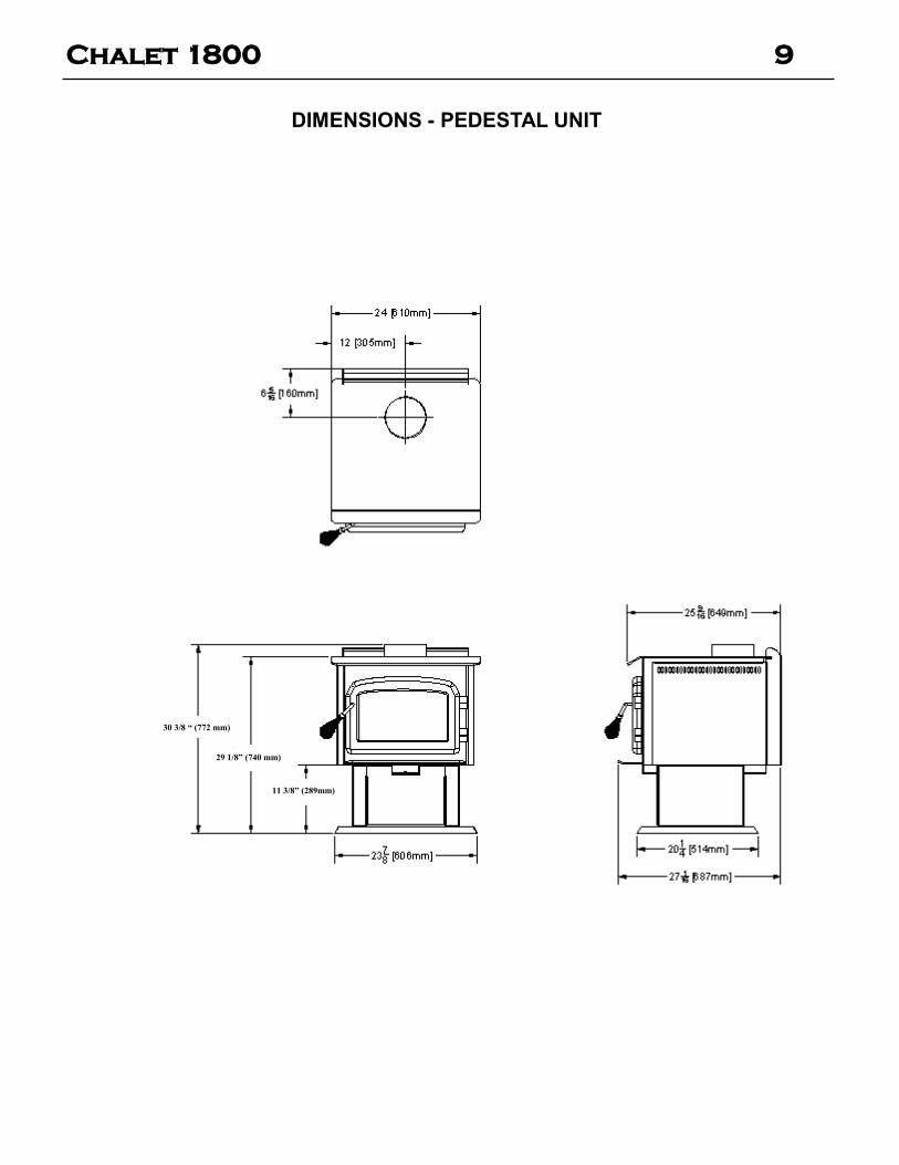
DIMENSIONS - PEDESTAL UNIT
11 3/8” (289mm)
29 1/8” (740 mm)
30 3/8 “ (772 mm)
Chalet 1800 10
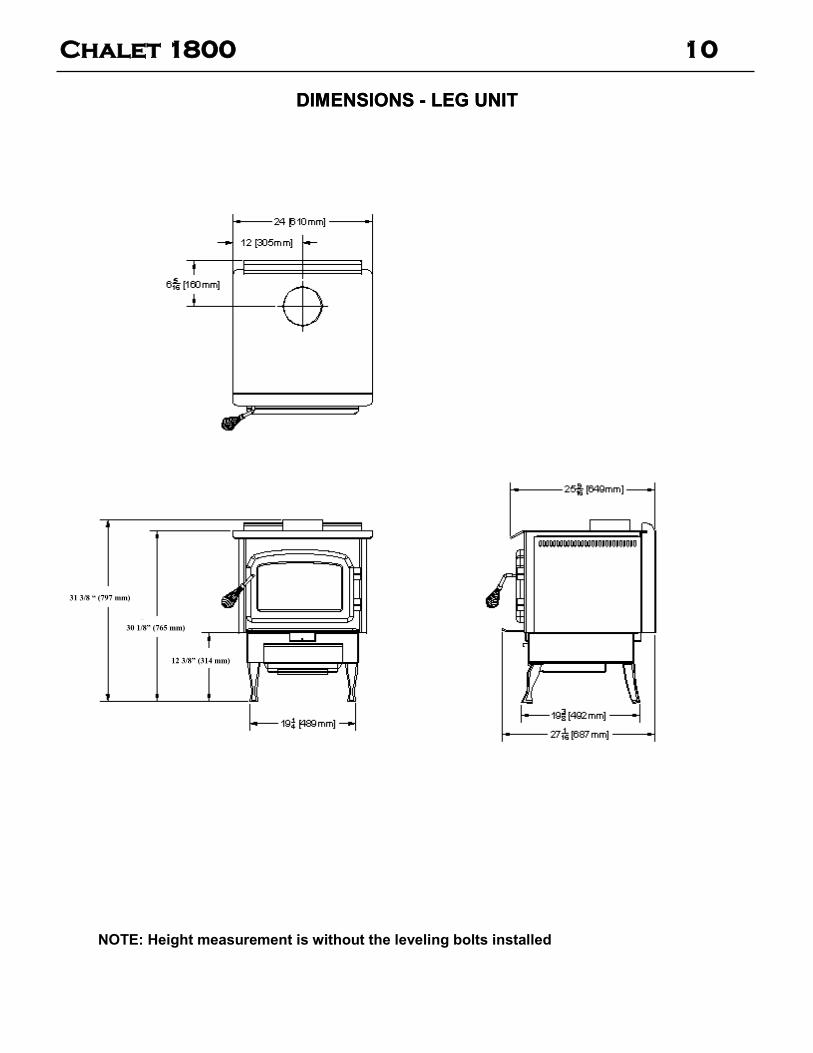
DIMENSIONS - LEG UNIT DIMENSIONS - LEG UNIT
NOTE: Height measurement is without the leveling bolts installed
31 3/8 “ (797 mm)
30 1/8” (765 mm)
12 3/8” (314 mm)
Chalet 1800 11
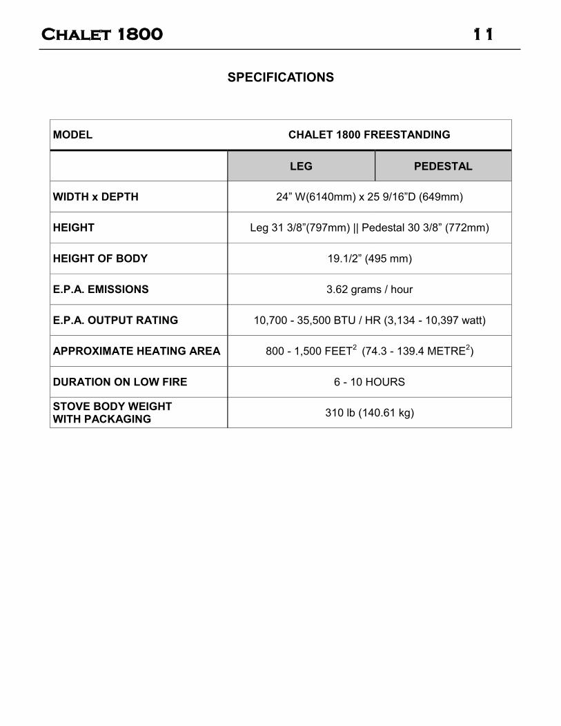
SPECIFICATIONS
MODEL CHALET 1800 FREESTANDING
LEG PEDESTAL
WIDTH x DEPTH 24” W(6140mm) x 25 9/16”D (649mm)
HEIGHT Leg 31 3/8”(797mm) || Pedestal 30 3/8” (772mm)
HEIGHT OF BODY 19.1/2” (495 mm)
E.P.A. EMISSIONS 3.62 grams / hour
E.P.A. OUTPUT RATING 10,700 - 35,500 BTU / HR (3,134 - 10,397 watt)
APPROXIMATE HEATING AREA 800 - 1,500 FEET2 (74.3 - 139.4 METRE
2)
DURATION ON LOW FIRE 6 - 10 HOURS
STOVE BODY WEIGHT WITH PACKAGING
310 lb (140.61 kg)
Chalet 1800 12
1. For easier assembly, tip the stove body on its back (preferably onto a soft surface to prevent scratching).
2. Slide the pedestal up against the bottom of the stove. You will be aligning the 4 holes in the corners of the pedestal with the corre-sponding holes in the base of the stove.
3. Use a centering device, such as a center punch and lift one corner of the pedestal and push the centering device loosely through the hole in the pedestal corner and into the “Tee” nut in the base of the stove (If you haven’t removed the bricks, be very careful not to loosen them - two people would be helpful for this job)
PEDESTAL ASSEMBLY
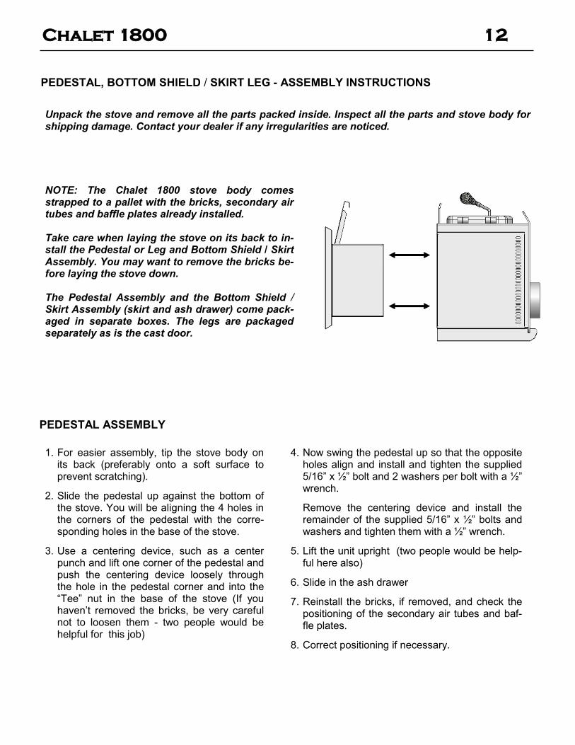
NOTE: The Chalet 1800 stove body comes strapped to a pallet with the bricks, secondary air tubes and baffle plates already installed. Take care when laying the stove on its back to in-stall the Pedestal or Leg and Bottom Shield / Skirt Assembly. You may want to remove the bricks be-fore laying the stove down. The Pedestal Assembly and the Bottom Shield / Skirt Assembly (skirt and ash drawer) come pack-aged in separate boxes. The legs are packaged separately as is the cast door.
PEDESTAL, BOTTOM SHIELD / SKIRT LEG - ASSEMBLY INSTRUCTIONS
4. Now swing the pedestal up so that the opposite holes align and install and tighten the supplied 5/16” x ½” bolt and 2 washers per bolt with a ½” wrench.
Remove the centering device and install the remainder of the supplied 5/16” x ½” bolts and washers and tighten them with a ½” wrench.
5. Lift the unit upright (two people would be help-ful here also)
6. Slide in the ash drawer
7. Reinstall the bricks, if removed, and check the positioning of the secondary air tubes and baf-fle plates.
8. Correct positioning if necessary.
Unpack the stove and remove all the parts packed inside. Inspect all the parts and stove body for shipping damage. Contact your dealer if any irregularities are noticed.

Chalet 1800 13
LEG ASSEMBLY This applies to all painted and plated cast legs
1. Thread the 1/4” x 1” leveling bolts into the bottom of the legs
2. Slip the 5/16” x 3/4” bolts through the very bottom of the Bottom Shield / Skirt and install the supplied washer and nut .
3. Slide each leg under the washer and tighten the nuts. Do not over-tighten.
NOTE: Back leg sits flush with the back and side corner while the front leg backs up against the front stop.
BOTTOM SHIELD / SKIRT ASSEMBLY
1. For easier assembly, tip the stove body on its back (preferably onto a soft surface to prevent scratch-ing).
2. Slide the Bottom Shield / Skirt Assembly up against the bottom of the stove. You will be aligning the 4 holes in the corners of the Bottom Shield / Skirt Assembly with the corresponding holes in the base of the stove.
3. Use a centering device, such as a center punch and lift one corner of the Bottom Shield / Skirt Assem-bly and push the centering device loosely through the hole in the Bottom Shield / Skirt Assembly corner and into the “Tee” nut in the base of the stove (If you haven’t removed the bricks, be very careful not to loosen them - two people would be helpful for this job)
4. Now swing the Bottom Shield / Skirt Assembly up so that the opposite holes align and install and tighten the supplied 5/16” x ½” bolt and 2 washers per bolt with a ½” wrench. Remove the centering device and install the remainder of the supplied 5/16” x ½” bolts and washers and tighten them with a ½” wrench.
5. Lift the unit upright and place it into position on the floor (two people would be helpful here also). CAU-
TION! DO NOT TILT THE UNIT ON THE CAST IRON LEGS.
6. Slide in the ash drawer.
7. Reinstall the bricks, if removed, and check the positioning of the secondary air tubes and baffle plates. Correct positioning if necessary.
8. Level the stove by adjusting the leveling bolts in the bottom of each leg.
5 / 16” x 3/4” bolts & washers & nuts
Front leg stop

Chalet 1800 14
The door comes assembled with the glass and gasket.
1. Run the threaded end of the handle through the hole in the cast door.
2. Insert the clevis pin into the roller and washer.
3. Insert the end of the clevis pin assembly into the hole in the end of the handle
4. Close the door and see how the door closes. If it is too tight, turn the handle clockwise to loosen it. If it is too loose, turn the handle counter clockwise to bring the door closer to the stove body.
5. To verify that the doors are well sealed, insert a piece of paper between the door and the stove body. You shouldn’t be able to pull the paper out. Tighten it to the point where the paper is starting to tear when you are pulling it out.
6. Insert the cotter pin into the end of the clevis pin to keep the assembly from coming apart.
7. Attach spring handle by rotating the spring counter clockwise onto the rod. Ensure that the spring screws onto the rod at least ½”.
9. Cover the holes with the two decorative plug buttons
Clevis Pin Cotter Pin
Roller
Washer
Cotter pin goes through clevis pin as shown here:
CAUTION: THIS UNIT CONTAINS SMALL PARTS DURING ASSEMBLY THAT SHOULD BE KEPT AWAY FROM CHILDREN DUE TO CHOKING HAZARD WHICH COULD RESULT IN PERSONAL INJURY OR DEATH.
Chalet 1800 15
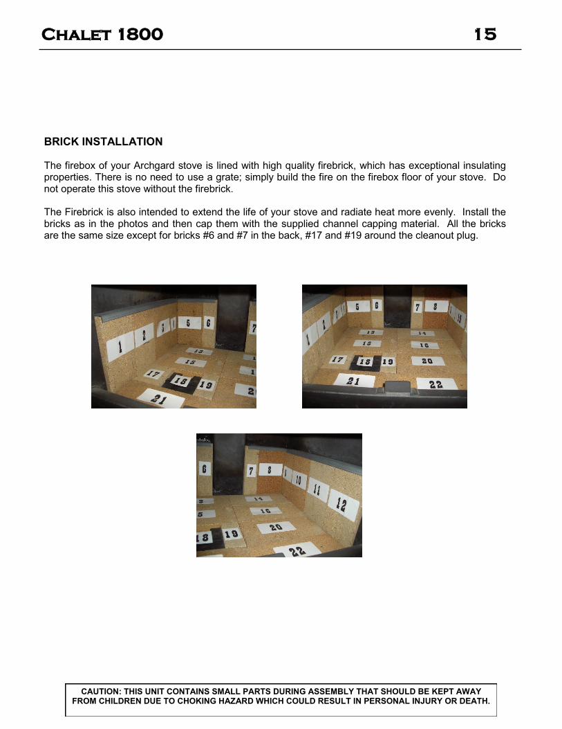
BRICK INSTALLATION The firebox of your Archgard stove is lined with high quality firebrick, which has exceptional insulating properties. There is no need to use a grate; simply build the fire on the firebox floor of your stove. Do not operate this stove without the firebrick. The Firebrick is also intended to extend the life of your stove and radiate heat more evenly. Install the bricks as in the photos and then cap them with the supplied channel capping material. All the bricks are the same size except for bricks #6 and #7 in the back, #17 and #19 around the cleanout plug.
CAUTION: THIS UNIT CONTAINS SMALL PARTS DURING ASSEMBLY THAT SHOULD BE KEPT AWAY FROM CHILDREN DUE TO CHOKING HAZARD WHICH COULD RESULT IN PERSONAL INJURY OR DEATH.

Chalet 1800 16
The Air Tubes in the Archgard Chalet 1800 come already assembled with the baffle plates installed. If for some reason they need to be installed, the following guidelines must be adhered to.
1) Open the Archgard Freestanding Chalet 1800 door.
2) Slide the tube into the right hand side hole, as far as possible and then bring it back into the hole on the left hand side lining up the “relief or notch” cut into the tube on that side until it locks into position. If the tube will not slide in easily, simply use a pair of vise grips or pliers and tap it into place with a ham-mer. A tighter fit will ensure the tube will not move when the unit is burning. NOTE: The holes in the two back tubes are larger than the holes in the two front tubes. The left hand side of the tubes have little “notches” or “reliefs” cut into them that mate with the left hand side of the stove that
align the air hole for proper combustion. (Photo 1)
3) Continue to install the other three tubes in the same manner.
4) Before installing the final air tube, slide the a lightweight baffle plate over the air tubes (leaving the step joint in the middle) from the front and then push it to the back and over to side of the stove as far as it can go. Do the same with the other lightweight baffle plate ensuring that the step in the middle will overlap the previous lightweight baffle plate. (Photo 2)
5) When both lightweight baffle plate are in, install the fourth secondary air tube. (Photo 3)
6) After the secondary air tube is installed, reach in and pull the two halves of the lightweight baffle plates, overlapping them and making sure they are pushed back as far as they can go. (Photo 4)
Handle the ceramic baffle plates with care as they are fragile.
AIR TUBE INSTALLATION
1 2
3 4
Chalet 1800 17
LISTED COMPONENTS FOR MOBILE HOME INSTALLATION
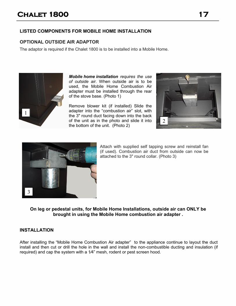
OPTIONAL OUTSIDE AIR ADAPTOR
The adaptor is required if the Chalet 1800 is to be installed into a Mobile Home.
Attach with supplied self tapping screw and reinstall fan (if used). Combustion air duct from outside can now be attached to the 3" round collar. (Photo 3)
Mobile home installation requires the use of outside air. When outside air is to be used, the Mobile Home Combustion Air adapter must be installed through the rear of the stove base. (Photo 1) Remove blower kit (if installed) Slide the adapter into the “combustion air” slot, with the 3" round duct facing down into the back of the unit as in the photo and slide it into the bottom of the unit. (Photo 2)
3
1
2
On leg or pedestal units, for Mobile Home Installations, outside air can ONLY be brought in using the Mobile Home combustion air adapter .
INSTALLATION
After installing the “Mobile Home Combustion Air adapter” to the appliance continue to layout the duct install and then cut or drill the hole in the wall and install the non-combustible ducting and insulation (if required) and cap the system with a 1⁄4” mesh, rodent or pest screen hood.

Chalet 1800 18
1. Remove the fan assembly from the box and inspect for any damage to the assembly. If damage is no-ticed call your dealer, distributor or courier company and have components replaced before installing kit.
2. Locate the 2 holes in the bottom back of the heat shield of the stove (shown in the photo).
3. Locate the 2 holes it the back top of the fan (with the louver facing back)
4. With the two #8 self tapping screws at the ready, slide the outlet end of the fan up into the rear heat shield lining up the 2 holes with each other.
5. After aligning holes, secure the fan to the rear heat shield using the two screws provided.
CAUTION: The connection cord should not be in contact with any hot surfaces. Do not route cord un-der or in front of unit.
BLOWER / FAN INSTALLATION
WARNING: Electrical Grounding Instructions This appliance is equipped with a three-pronged (grounding) plug for your protection against shock haz-ard and should be plugged directly into a properly grounded three-prong receptacle. Do not cut or re-move the grounding prong from this plug.
FAN OPERATION
The Chalet 1800 is certified for operation with or without the optional fan and may be installed at any time by attachment at the back of the stove and plugging in the 3-prong power cord.
Electrical Rating = 115V AC / 1.0 amps
Fan Output Rating = 150 c.f.m.
PART # FK-1800 FS
CAUTION Label all wires prior to disconnection when
servicing controls. Wiring errors can cause improper and dangerous operation
FAN WIRING DIAGRAM
The Chalet 1600 fan kit comes complete with a temperature activated fan and solid stat speed control. The heat sensor is factory set to close the circuit to the fan speed control at 1100 F (430 C) and will turn off the fan when the temperature falls below 800 F (270 C). The speed can be adjusted up/down and off with the knob on the side of the fan housing
Chalet 1800 19
RESIDENTIAL INSTALLATION
CAUTION: At no time can unlabelled parts, or substitute parts made for another chimney system be used. Install as per chimney manufacturer's installation instructions.
1. Please read this entire manual before you install and use your new Chalet 1800 woodstove. Failure to follow instructions may result in property damage, bodily injury or even death. Be aware that local Codes and Regulations may override some items in this manual. Check with your local Authority Having Jurisdiction.
2. Select a location for your Archgard Chalet 1800 Stove. Double check the clearances on the label and set the stove in place.
3. For a vertical installation, suspend a plumb bob from the ceiling over the exact center of your stove flue collar or use a laser centering device and mark the ceiling to indicate the center of the chimney.
4. Check that the intended location does not interfere with trusses, joists or rafters before proceeding further.
5. Cut a hole in the ceiling and roof to suit the chimney system and do any necessary framing as required by the chimney manufacturer. Maintain the integrity of the vapor barrier. NOTE: Interior chimneys shall be enclosed where they extend through closets, storage areas, occupied spaces, or anyplace where the surface of the chimney could be contacted by persons or combustible materials.
6. Install required supports, firestops, radiation shields, etc. Assemble chimney sections so that the finished length is cradled in the support and protruding through the roof, install the flashing and storm collar (in some cases you may have to install the flashing before the section of chimney goes through the roof) . Attach rain cap. Depending on how much exposed chimney you have, you may need to install roof braces.
Install chimney according to chimney manufacturer’s instructions. The performance of your woodstove is largely dependant on the chimney system. Too short a chimney can cause difficult start-ups, dirty glass, smoking problems when the door is open, and even reduced heat output. Too tall a chimney can cause excessive draft which can result in very short burn times and excessive heat output and possible overheating of the stove. CAUTION: The chimney should be the same size as the 6" flue outlet on the stove. The Chalet 1800 woodstove must be connected to a listed UL 103 HT chimney in the USA or a listed ULC S629 chimney in Canada or a code approved masonry chimney with a flue liner. 7. The floor pad (ember pad) must be of non-combustible material and must extend 16" in front of the
door opening and 6" to the sides and rear of the unit. Note: In Canada, the floor pad (ember pad) must be of non-combustible material and must extend 18" (450mm) in front of the door opening and 8" (200mm) to the sides and rear of the unit. See your local inspector or the CSA B365 in Canada or NFPA 211 in USA 8. If you are installing the mobile home combustion air adapter, position the stove on the floor/hearth
pad (ember pad) and mark the location of the hole in the wall, drill or cut the hole and install the ducting and hood, with rodent screen and insulate if necessary.
9. When the stove is positioned with the flue collar centered under the chimney, hook up the connector
pipe and fasten it to the flue collar which has provisions for 3 screws and to the chimney as per
manufacturer’s instructions.

Chalet 1800 20
RESIDENTIAL INSTALLATION (cont’d)
11) In seismically active areas, Archgard recommends that your unit be secured to the floor by using ¼” lag bolts in the bolt down holes on the pedestal or legs (the same ones used for Mobile Home installations).
12) For residential installations using 6" "C" Vent (single wall), the chimney connector must be at least 24 gauge steel. Do not use galvanized pipe. For Mobile Home installation, use only listed air insulated double wall connector.
13) Do not connect this unit to a chimney serving another
appliance.
14) A chimney connector cannot pass through an attic or roof space, closet or similar concealed space, or a floor, ceiling, wall or partition of combustible construction. In Canada, if passage through a wall, or partition of combustible construction is desired, the installation shall conform to CAN/CSA-B365, Installation Code for Solid-Fuel-Burning Appliances and Equipment. In the U.S.A. install according to NFPA 211.
Do not connect your Archgard Woodstove to an air distribution duct.
Check with chimney manufacturer’s installation instructions for more thorough / detailed instructions for installing their chimney
Horizontal Installation Vertical Installation
Chalet 1800 21
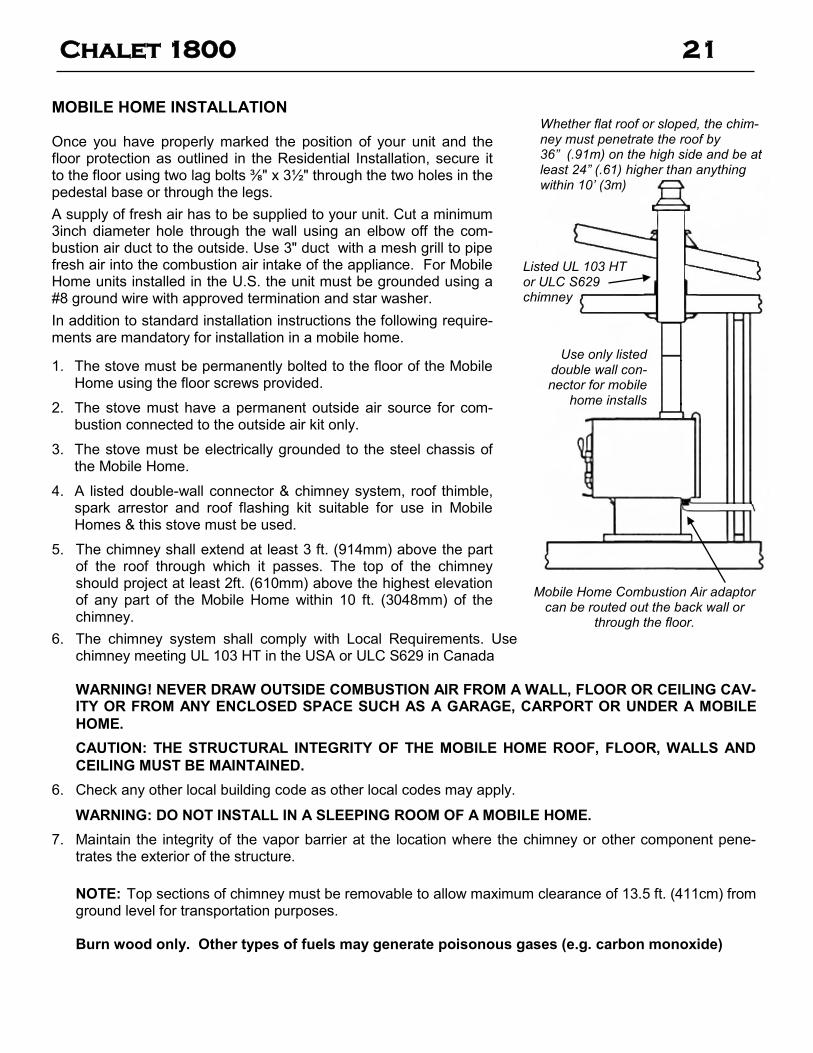
MOBILE HOME INSTALLATION Once you have properly marked the position of your unit and the floor protection as outlined in the Residential Installation, secure it to the floor using two lag bolts ⅜" x 3½" through the two holes in the pedestal base or through the legs.
A supply of fresh air has to be supplied to your unit. Cut a minimum 3inch diameter hole through the wall using an elbow off the com-bustion air duct to the outside. Use 3" duct with a mesh grill to pipe fresh air into the combustion air intake of the appliance. For Mobile Home units installed in the U.S. the unit must be grounded using a #8 ground wire with approved termination and star washer.
In addition to standard installation instructions the following require-ments are mandatory for installation in a mobile home.
1. The stove must be permanently bolted to the floor of the Mobile Home using the floor screws provided.
2. The stove must have a permanent outside air source for com-bustion connected to the outside air kit only.
3. The stove must be electrically grounded to the steel chassis of the Mobile Home.
4. A listed double-wall connector & chimney system, roof thimble, spark arrestor and roof flashing kit suitable for use in Mobile Homes & this stove must be used.
5. The chimney shall extend at least 3 ft. (914mm) above the part of the roof through which it passes. The top of the chimney should project at least 2ft. (610mm) above the highest elevation of any part of the Mobile Home within 10 ft. (3048mm) of the chimney.
6. The chimney system shall comply with Local Requirements. Use chimney meeting UL 103 HT in the USA or ULC S629 in Canada
WARNING! NEVER DRAW OUTSIDE COMBUSTION AIR FROM A WALL, FLOOR OR CEILING CAV-ITY OR FROM ANY ENCLOSED SPACE SUCH AS A GARAGE, CARPORT OR UNDER A MOBILE
HOME.
CAUTION: THE STRUCTURAL INTEGRITY OF THE MOBILE HOME ROOF, FLOOR, WALLS AND
CEILING MUST BE MAINTAINED.
6. Check any other local building code as other local codes may apply.
WARNING: DO NOT INSTALL IN A SLEEPING ROOM OF A MOBILE HOME.
7. Maintain the integrity of the vapor barrier at the location where the chimney or other component pene-trates the exterior of the structure.
NOTE: Top sections of chimney must be removable to allow maximum clearance of 13.5 ft. (411cm) from ground level for transportation purposes. Burn wood only. Other types of fuels may generate poisonous gases (e.g. carbon monoxide)
Mobile Home Combustion Air adaptor can be routed out the back wall or
through the floor.
Whether flat roof or sloped, the chim-ney must penetrate the roof by 36” (.91m) on the high side and be at least 24” (.61) higher than anything within 10’ (3m)
Use only listed double wall con-nector for mobile
home installs
Listed UL 103 HT or ULC S629 chimney
Chalet 1800 22
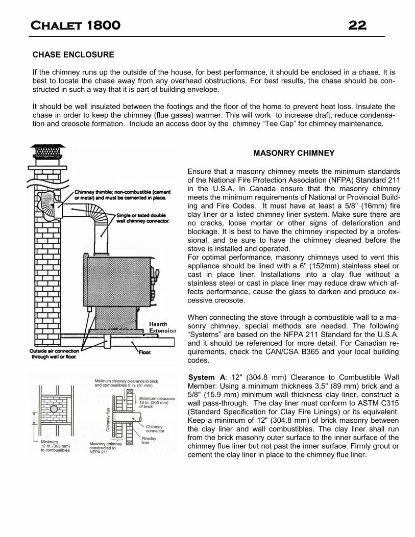
CHASE ENCLOSURE If the chimney runs up the outside of the house, for best performance, it should be enclosed in a chase. It is best to locate the chase away from any overhead obstructions. For best results, the chase should be con-structed in such a way that it is part of building envelope. It should be well insulated between the footings and the floor of the home to prevent heat loss. Insulate the chase in order to keep the chimney (flue gases) warmer. This will work to increase draft, reduce condensa-tion and creosote formation. Include an access door by the chimney “Tee Cap” for chimney maintenance.
MASONRY CHIMNEY Ensure that a masonry chimney meets the minimum standards of the National Fire Protection Association (NFPA) Standard 211 in the U.S.A. In Canada ensure that the masonry chimney meets the minimum requirements of National or Provincial Build-ing and Fire Codes. It must have at least a 5/8" (16mm) fire clay liner or a listed chimney liner system. Make sure there are no cracks, loose mortar or other signs of deterioration and blockage. It is best to have the chimney inspected by a profes-sional, and be sure to have the chimney cleaned before the stove is installed and operated. For optimal performance, masonry chimneys used to vent this appliance should be lined with a 6" (152mm) stainless steel or cast in place liner. Installations into a clay flue without a stainless steel or cast in place liner may reduce draw which af-fects performance, cause the glass to darken and produce ex-cessive creosote. When connecting the stove through a combustible wall to a ma-sonry chimney, special methods are needed. The following “Systems” are based on the NFPA 211 Standard for the U.S.A. and it should be referenced for more detail. For Canadian re-quirements, check the CAN/CSA B365 and your local building codes. System A: 12" (304.8 mm) Clearance to Combustible Wall Member: Using a minimum thickness 3.5" (89 mm) brick and a 5/8" (15.9 mm) minimum wall thickness clay liner, construct a wall pass-through. The clay liner must conform to ASTM C315 (Standard Specification for Clay Fire Linings) or its equivalent. Keep a minimum of 12" (304.8 mm) of brick masonry between the clay liner and wall combustibles. The clay liner shall run from the brick masonry outer surface to the inner surface of the chimney flue liner but not past the inner surface. Firmly grout or cement the clay liner in place to the chimney flue liner.

Chalet 1800 23
MASONRY CHIMNEY (cont’d)
System B: 9" (228.6 mm) Clearance to Combustible Wall Member: Using a 6" (152.4 mm) inside diameter, listed, factory-built Solid-Pak chimney section with insula-tion of 1" (25.4 mm) or more, build a wall pass-through with a minimum 9" (228.6 mm) air space between the outer wall of the chimney length and wall combustibles. Use sheet metal supports fastened securely to wall sur-faces on all sides, to maintain the 9" (228.6 mm) air space. When fastening supports to chimney length, do not penetrate the chimney liner (the inside wall of the Solid-Pak chimney). The inner end of the Solid-Pak chimney section shall be flush with the inside of the ma-sonry chimney flue, and sealed with a non-water soluble refractory cement. Use this cement to also seal to the brick masonry penetration. System C: 6" (152.4 mm) Clearance to Combustible Wall Member: Starting with a minimum 24 gage (.024" [.61 mm]) 6" (152.4 mm) metal chimney connec-tor, and a minimum 24 gage ventilated wall thimble which has two air channels of 1" (25.4 mm) each, con-struct a wall pass-through. There shall be a minimum 6" (152.4) mm separation area containing fiberglass in-sulation, from the outer surface of the wall thimble to wall combustibles. Support the wall thimble, and cover its opening with a 24-gage minimum sheet metal support. Maintain the 6" (152.4 mm) space. There should also be a support sized to fit and hold the metal chimney con-nector. See that the supports are fastened securely to wall surfaces on all sides. Make sure fasteners used to secure the metal chimney connector do not penetrate chimney flue liner. System D: 2" (50.8 mm) Clearance to Combustible Wall Member: Start with a solid-pak listed factory built chim-ney section at least 12" (304 mm) long, with insulation of 1" (25.4 mm) or more, and an inside diameter of 8" (2 inches [51 mm] larger than the 6" [152.4 mm] chimney connector). Use this as a pass-through for a minimum 24-gage single wall steel chimney connector. Keep solid-pak section concentric with and spaced 1" (25.4 mm) off the chimney connector by way of sheet metal support plates at both ends of chimney section. Cover opening with and support chimney section on both sides with 24 gage minimum sheet metal supports. See that the sup-ports are fastened securely to wall surfaces on all sides. Make sure fasteners used to secure chimney flue liner.

Chalet 1800 24
RECOMMENDED MINIMUM CHIMNEY HEIGHTS
The chimney must be at least 3 ft. (.9m) higher than the highest point where it passes through the roof and at least 2 ft. (.6m) higher than the highest part of the roof or structure within 10 ft. (3m) of the chimney, measured horizontally. These are code requirements and cannot guarantee a suitable draft. We rec-ommend using a minimum total system height of 12 ft. (3.6m), measured from the flue collar to the bottom of the chimney cap)
# OF ELBOWS ELEVATION (FT) ABOVE SEA
LEVEL 0 2 x 15o
4 x 15o
o 2 x 30o
4 x 30o
2 x 45o
4 x 45o
0-1000 12.0 13.0 14.0 15.0 18.0 16.0 20.0
1000-2000 12.5 13.5 14.5 15.5 19.0 16.5 21.0
2000-3000 13.0 14.0 15.0 16.0 19.5 17.0 21.5
3000-4000 13.5 14.5 15.5 17.0 20.0 18.0 22.5
4000-5000 14.0 15.0 16.0 17.5 21.0 18.5 23.0
5000-6000 14.5 15.5 17.0 18.0 21.5 19.0 24.0
6000-7000 15.0 16.0 17.5 18.5 22.5 20.0 25.0
7000-8000 15.5 16.5 18.0 19.0 23.0 20.5 25.5
8000-9000 16.0 17.0 18.5 20.0 24.0 21.0 26.5
9000-10000 16.5 17.5 19.0 20.5 24.5 22.0 27.0
NOTE: No more than two offsets (four elbows) allowed. Two 45o elbows equal one 90o elbow.
(Measured from the top of the unit)
Recommended Flue Height
Elevation Example a) Example b) 0' 18' 21' 1000' 18.72' 21.84' 2000' 19.44' 22.68' 5000' 21.60' 25.20'
1) At sea level minimum height is 12' straight, off the top of the appliance.
2) Add the following vertical height to compensate for:
45 deg. elbow = 1 ft. 90 deg. elbow = 2 ft. "T" = 3 ft.
Each foot of horizontal run = 2 ft.
3) Add 4% overall for each 1000' above sea level.
Examples:
a) 1-1/2 ft. of horizontal run = 3 ft. one "T" = 3 ft. Total Addition (at sea level) = 6 ft. b) One 90 deg. elbow = 2 ft. 2 ft. of horizontal run = 4 ft. one "T" = 3 ft. Total Addition (at sea level) = 9 ft.

Chalet 1800 25
VENT SPECIFICATIONS
Your Archgard Chalet 1800 was designed for and tested on a 6” (152mm) chimney, 15’ (4.57m) high, (includes stove height) measured from the base of the stove. The further your stack height or diameter varies from this configuration, the greater the possibility of performance problems. In addition, exterior conditions such as roof line, surrounding trees, prevailing winds and nearby hills can influence stove performance. Your local dealer is the expert in your geographic area and can usually make suggestions or discover solu-tions that will correct any flue problem you may have, allowing your woodstove and its flue system to operate correctly and provide safe and economical heat for your home.
Single Wall: Six inch (6”) (152mm) diameter, minimum 24 MSG black or blued steel connector pipe.
Double Wall / Mobile Home: any six inch (6”) (152mm) diameter, listed double wall air insulated con-nector pipe.
Chimney: listed factory-built chimney type UL103 HT in USA or CAN/ULC-S269 in Canada, or a code com-pliant masonry chimney. (Mobile Home must be equipped with a spark arrestor)
OPERATION
Air quality is important to all of us, and if we choose to use wood to heat our homes, we should do so respon-sibly. To do this, we need to learn to burn our stoves in the cleanest way possible. Doing this will allow us to continue using our wood stoves for many years to come.
AIR CONTROL - PRIMARY AIR SYSTEM
(DRAFT CONTROL)
The primary air enters at the base of the firebox and travels through passages toward the upper front of the firebox, near the top of the glass door. This preheated air supplies the necessary fresh oxygen to mix with the unburned gases, helping to create secondary combus-tions. This air is regulated by the Primary Control. For more primary air, pull the control out. For less air, push the control in.
Pull this control all the way out when first starting the stove. Once the fire has been established you may ad-just this control to set the burn rate of the fire. If this damper is closed at first start-up, the fire will burn very slowly and could soot the appliance.
When shutting down the stove, fully open the air con-trol. This allows the chimney temperatures to remain as high as possible for as long as possible. Cold chimney temperatures create creosote.
FIRST FIRE
1. The first step in building a fire is to open the air con-trol.
2. Crumple four or five sheets of newspaper and put them on the firebox in the centre of the heater – be generous and you will have more success. Hold the paper down with 10 to 15 pieces of dry kindling. Softwoods, such as cedar and pine, make good kin-dling (use the species available in your region).
Place the kindling on and behind the newspaper, so that the combustion air reaches the newspaper first where you light it. It is also a good idea to add one or two small pieces of dry firewood to the kindling load before lighting.
3. Light the newspaper and close (but don’t latch) the door. When the paper is flaming brightly and the kindling catches and the chimney is producing strong draft, latch the door. CAUTION: Never leave the unit unattended if door is left open. This pro-cedure is for start-up only, as the unit may over
-heat if the door is left open for too long.
4. When the flames from the kindling load begin to subside, gradually add several small pieces of wood. Avoid smothering the fire with the new wood. Place the pieces on and behind the burning kin-dling. Wood should be flaming until it is reduced to charcoal. Never let a fire smoulder because smoul-dering wastes wood. For the first few hours, the in-sert will give off an odor from the paint. You may want to leave some windows and/or doors open to provide adequate ventilation while this temporary condition exists. In some instances, your smoke de-tector may alarm. Do not build hot fires in your in-sert for the first few days until the paint has had a chance to cure with some moderate fires.
Chalet 1800 26
5. Before opening your door to reload, open draft fully for approximately 10 to 15 seconds until fire has been reestablished. This will minimize any smoking.
All fuel burning appliances consume oxygen during operation. It is important that you supply a source of fresh air to your unit while burning. Ignore the fire until you notice the room, space or house cooling off. A new load cools the firebox, so it needs to be heated up again. Then add the right amount of wood to suit the conditions. Wood burns best in cycles. A cycle starts when wood is placed on and behind a raked coal bed. A cycle ends when the load is reduced to the same sized coal bed. We recommend that when you first fire up your Chalet 1800, you leave a door and/or window open in or-der to vent the smoke that may be created from the unit’s paint curing. The paint will smell a little for the first burn or two as it cures.
TROUBLESHOOTING
The most common factors for poor draft are:
a) Air supply/House depressurization
b) Environmental conditions
c) Cold chimneys
d) Poor chimney/connector installation/ design and maintenance
a) Air supply / House depressurization – Inside the home, household appliances such as clothes dryers, bathroom fan, central vacuums, forced-air furnaces, etc, compete for air, resulting in air starvation to the fire. This creates a condition known as negative pressure. When a negative pressure situation is experienced, the combustion gases can be drawn from the chimney and into the house. This condition is commonly referred to as down-drafting. Increased amounts of insulation, vinyl windows and extra caulking in various places can all keep heat in but may also make a home more airtight. Seal the leaks that are high in the house because the house acts as a chimney and as hot air leaves the house at the ceiling level, more air comes in at lower levels to make up for the air that leaves. Make sure there is adequate air for the appliance in the house.
b) Environmental Conditions - High trees, low-lying house location such as in a valley, tall buildings or structures surrounding your house and windy conditions can cause poor draft.
c) Cold Chimney Temperature - Avoid cold chimney temperatures by burning a hot fire for the first fifteen to forty minutes, being careful not to over-fire the stove. Where possible, install a thermometer on or in the flue pipe so temperatures can be monitored.
d) Chimney Installation and Maintenance - Avoid using too many elbows or long horizontal runs. Too short a chimney can cause difficult start-up, dirty glass, smoking when door is open, and even re-duced heat output. Too tall a chimney may prompt excessive draft, which can result in very short burn times and excessive heat output. If in doubt, contact a chimney expert and/or chimney manufacturer for help. Clean chimney, rain caps and especially the spark arrestor regularly, to prevent creosote build-up, which will significantly reduce chimney draw.

Chalet 1800 27
TROUBLESHOOTING
PROBLEM CAUSE CURE
Glass is Dirty 1. Wood is wet Use dry wood
2. Turning down air control or damper too soon
Do not turn down until:
❖ there is a good bed of coals
❖ the wood is charred
3. Draft too low – Improper chimney height and / or di-ameter
Flue pipe too long, too many offsets or too large a diame-ter
❖ Chimney plugged or restricted,
check flue
❖ Provide outside air for combus-
tion
4. Door gasket leakage ❖ Replace gasket
❖ Check latch
5. Excessive Creosote Buildup
See 1,2,3, above
Low Heat Output 1. Wood is wet Use dry wood
2. Fire too small Build a larger fire
3. Draft too low Chimney plugged or restricted, inspect and clean (See 3 above)
Won't Burn Overnight 1. Air control is set too high Set control lower
2. Not enough wood Un-split wood is preferred for over-night burns
3. Draft too high Excessive chimney height and / or diameter
Stove Won't Burn 1. Combustion air supply blocked
❖ Check outside air supply for ob-
struction
❖ Check that room air cover is
removed
2. Draft too low ❖ Chimney plugged or restricted,
inspect and clean
❖ Chimney / flue pipe oversized
or otherwise unsuitable

Chalet 1800 28
CREOSOTE AND CHIMNEY FIRES When wood burns slowly - as it often does in a conventional, airtight stove or furnace - it makes a smoky fire and produces more creosote deposits than a quick, hot fire does. Creosote is a highly flamma-ble material. If it ignites near the base of the chimney, it can produce a raging fire that travels up the chimney, creating extremely high temperatures as it spreads. The high temperature can damage the clay liners in a masonry chimney or the metal liner in a factory-built chimney. Although 650°C/2100oF chim-neys can withstand these temperatures, the heat causes extreme stress in the chimney. Chimney fires result from poor firing techniques combined with a lack of maintenance. If unseasoned wood (wood that hasn't been dried enough) is burned slowly in an old "airtight" heater, creosote can build up quickly and the risk of a chimney fire increases. When you operate wood-burning appliances properly, some creosote may still be deposited, but it will be less combustible. Instead of the black, tarry, highly flammable creosote from smoldering fires, proper firing may create small amounts of soft, flaky and dark brown deposits. You can prevent chimney fires. Have your chimney checked for creosote deposits regularly, until you find out how quickly it builds up in the system. Conventional wood heaters can produce creosote quickly be-cause they can't burn the wood as completely as advanced combustion designs. In severe cases of smol-dering, it may take only a few days for enough creosote to build up to sustain a chimney fire. The new, low-emission wood stoves, like the Archgard Chalet 1800 burn the wood so completely that, when oper-ated properly, their chimneys normally need cleaning only once a year. Never assume that the chimney is clean. Check it regularly to be sure, especially during the spring and fall. If you do have a chimney fire, have the chimney inspected and repaired, if necessary, before using the sys-tem again. A chimney fire is a clear sign of a problem with the appliance, the fuel or the way the system is operated. Make changes to avoid chimney fires in the future. Using an energy-efficient wood-burning appli-ance, like the Archgard Chalet 1800 , coupled with good installation and proper burning techniques, dra-matically lowers the chance of a chimney fire.
AVOIDING A CHIMNEY FIRE There are two ways to avoid chimney fires:
1. Do not let creosote build up to a point where a chimney fire is possible.
2. Do not have fires in the stove that may ignite chimney fires.
These are hot fires, such as when burning household trash, cardboard, Christmas tree limbs.
Remember, this is a wood stove, not a garbage burner.
FAILURE TO INSPECT AND CLEAN YOUR CHIMNEY SYSTEM REGULARLY CAN RESULT
IN A CHIMNEY FIRE, WHICH COULD DAMAGE THE CHIMNEY OR CAUSE A HOUSE FIRE.
Chalet 1800 29
IN CASE OF A CHIMNEY FIRE
1. Prepare to evacuate to ensure everyone's safety. Have a well understood plan of action for evacuation. Have a place outside where everyone is to meet.
2. Close the air inlet on the stove. 3. Call local fire department. Have a fire extinguisher handy. Contact your local municipal or provincial fire
authority for further information on how to handle a chimney fire. It is most important that you have a clearly understood plan on how to handle a chimney fire.
4. After the chimney fire is out, the chimney must be cleaned and checked for stress and cracks before starting another fire. Also check combustibles around the chimney and the roof.
The services of a competent or certified installer, (certified by the Wood Energy Technical Training program (WETT) – in Canada, National Fireplace Institute (NFI) - in U.S.A.) are strongly recommended.
SAFETY EQUIPMENT All homes with a fuel burning appliance should have at least one fire extinguisher in a central location known to all in the household along with a smoke detection device installed to the smoke detector manufacturer’s placement and installation instructions, and maintained on a regular basis. We also recommend all dwellings be equipped with a Carbon Monoxide Detector and have a practiced evacuation plan.
CHIMNEY MAINTENANCE It is very important to carefully maintain your Chalet 1800 stove, including burning seasoned wood and main-taining a clean stove and chimney system. Have the chimney cleaned before the burning season and as nec-essary during the season, as creosote deposits may build up rapidly. Moving parts of your stove require no lubrication. Have chimney system cleaned when a significant layer of creosote has accumulated (3 mm / ⅛" or more). At the end of the heating season, have the chimney/stove system inspected and if necessary cleaned/maintained. As a precaution, the chimney should be inspected at least once every month during the heating season to de-termine if creosote or soot has built up. Check spark arrestor screens at least every 2 to 4 weeks. If creosote or soot has accumulated, it should be cleaned or replaced to reduce the risk of chimney fire. Proper burning will leave the firebricks in the firebox a tan color, never black. Steel parts in the firebox will be light to dark brown, never black or shiny.
WOOD
The efficiency and convenience of your wood-heating system depend significantly on the quality of the fuel
wood you burn. The four main factors that influence how firewood burns are piece size, wood condition,
tree species and moisture content. The moisture content of the wood affects the rate at which it burns and the efficiency of combustion. The wood moisture content of unseasoned wood, can range between
35 and 60 percent by weight. Wood that is this wet is hard to ignite and slow to burn. It also hisses and
sizzles in the firebox. It combusts poorly and produces large amounts of air pollutants. Energy from the
burning fire is used to boil off the moisture, which reduces efficiency. Wet wood is the most common prob-
lem with wood heating. If you think you have a problem with your stove's performance, check the dryness
of your fuel first. Properly seasoned wood ignites readily, flames easily and burns efficiently.

Chalet 1800 30
WOOD (cont’d) The size of the firewood pieces affects the rate of combustion. Large pieces ignite and release their en-ergy slower than small pieces. Smaller, more finely split pieces are better for short, hot fires, while larger pieces suit extended firing cycles. The largest piece of wood for your Chalet 1800 should be no more than about 15 cm (6 in.) across and 18” long. Another factor that affects how firewood burns is the wood's condition. Wood that has been lying on the ground or has been cut too long ago and starting to rot, will be difficult to burn. Store two or three days' supply of wood indoors, making sure that it is clean and dry. In winter, when you bring wood di-rectly in from the cold outdoors and immediately load it into the appliance, it may initially cool the fire and prevent proper combustion. Remember, storing wet wood indoors could create mould inside the house, so you should limit the amount of wood that you store inside. Several tree species are used for firewood, and those you choose will affect your wood-burning system. The energy content of wood per dry kilogram (i.e., per unit of weight) is similar regardless of species (approximately 8,600 BTU/lb at 15% moisture content). However, the energy output from each piece of wood (weight per unit volume) of various species differs widely. Wood is generally sold by volume (cords), which means the energy per cord can differ widely among different species of wood. In general, hard-woods like maple and oak are denser and have more energy per piece than softwoods such as pine, spruce and cedar. Burn only dry seasoned wood. Store wood under cover, out of the rain and snow. Well-seasoned wood will not only minimize the chance of creosote formation, but will give you the most efficient fire. Even dry wood contains under 20% moisture by weight and should be burned hot enough to dry the wood out. The Chalet 1800 high-efficiency stove burns both hardwood and softwood equally well. Dead wood lying on the forest floor should be considered wet, and requires full seasoning time. Standing dead wood can be considered to be about two-thirds seasoned. The best way to tell if wood is dry enough to burn, is to use a moisture meter. If your wood sizzles in the fire, even though the surface is dry, it may not be fully seasoned. Splitting wood before it is stored reduces drying time. Wood should be stacked so that both ends of each piece are exposed to air, since more drying occurs through the cut ends than the sides. This is true even with wood that has been split. Store wood off the ground , under cover, such as in a shed, or covered with a tarp, plastic, tar paper, sheets of scrap plywood, etc., as uncovered wood can absorb water from rain or snow. Also, leave the sides ex-posed to the air to make sure that air can flow around the woodpile so that there will be no delaying the sea-soning process.
Chalet 1800 31
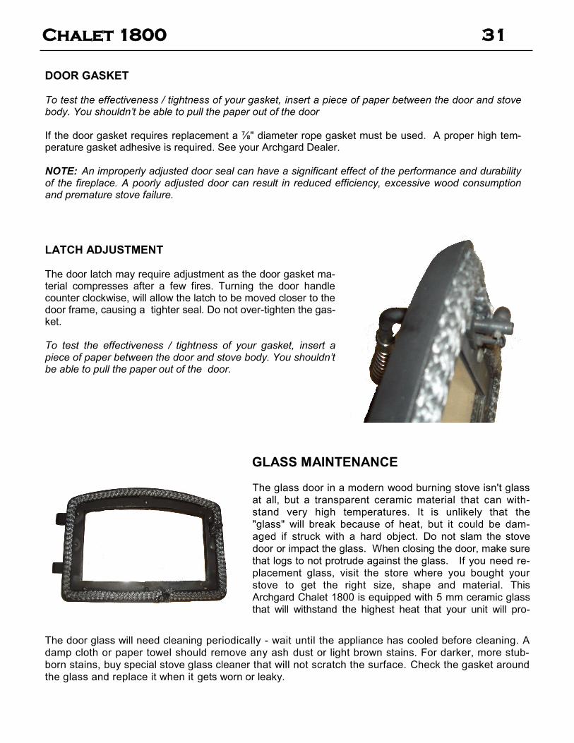
LATCH ADJUSTMENT The door latch may require adjustment as the door gasket ma-terial compresses after a few fires. Turning the door handle counter clockwise, will allow the latch to be moved closer to the door frame, causing a tighter seal. Do not over-tighten the gas-ket. To test the effectiveness / tightness of your gasket, insert a piece of paper between the door and stove body. You shouldn’t be able to pull the paper out of the door.
DOOR GASKET To test the effectiveness / tightness of your gasket, insert a piece of paper between the door and stove body. You shouldn’t be able to pull the paper out of the door If the door gasket requires replacement a ⅞" diameter rope gasket must be used. A proper high tem-perature gasket adhesive is required. See your Archgard Dealer. NOTE: An improperly adjusted door seal can have a significant effect of the performance and durability of the fireplace. A poorly adjusted door can result in reduced efficiency, excessive wood consumption and premature stove failure.
GLASS MAINTENANCE
The glass door in a modern wood burning stove isn't glass
at all, but a transparent ceramic material that can with-
stand very high temperatures. It is unlikely that the
"glass" will break because of heat, but it could be dam-
aged if struck with a hard object. Do not slam the stove
door or impact the glass. When closing the door, make sure
that logs to not protrude against the glass. If you need re-
placement glass, visit the store where you bought your
stove to get the right size, shape and material. This
Archgard Chalet 1800 is equipped with 5 mm ceramic glass
that will withstand the highest heat that your unit will pro-
The door glass will need cleaning periodically - wait until the appliance has cooled before cleaning. A
damp cloth or paper towel should remove any ash dust or light brown stains. For darker, more stub-
born stains, buy special stove glass cleaner that will not scratch the surface. Check the gasket around
the glass and replace it when it gets worn or leaky.
Chalet 1800 32
GLASS MAINTENANCE (cont’d) WARNING: Never clean this glass with an abrasive cleaner. Use only a cleaner recommended as a wood stove glass cleaner. Never clean the glass while it is hot; a serious burn can result. NOTE: A portion of the combustion air entering the firebox is deflected down over the inside of the door glass. This air flow “washes” the glass, helping to keep smoke from adhering to its surface. In a controlled combustion firebox temperatures are not always high enough to keep the glass perfectly clean. Less air will be flowing over the glass and the smoky, relatively cool condition of a low fire will cause the glass to become dark. Operating the stove with the Primary Air Control all the way open for 15-20 minutes should remove this built up coating. If the deposits on the glass are not very heavy, normal glass cleaners should work well. Heavier deposits may be removed using wood stove glass cleaner. Remember the drier the wood, the cleaner the glass.
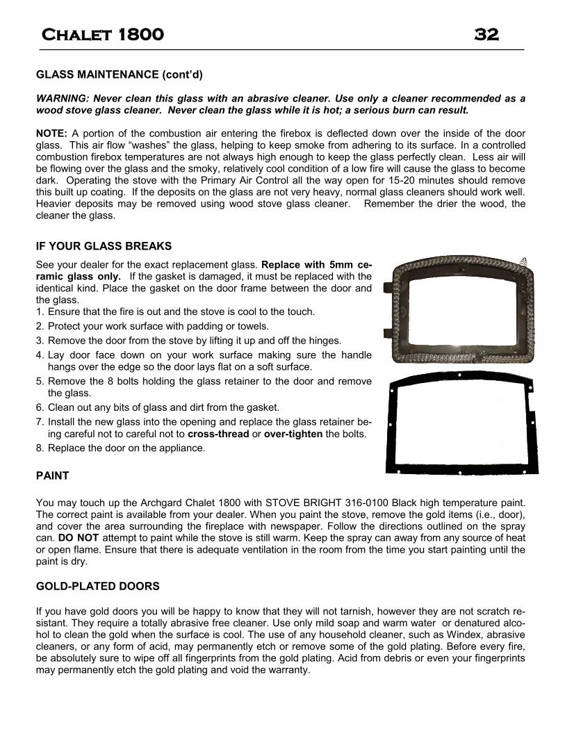
IF YOUR GLASS BREAKS
See your dealer for the exact replacement glass. Replace with 5mm ce-ramic glass only. If the gasket is damaged, it must be replaced with the identical kind. Place the gasket on the door frame between the door and the glass. 1. Ensure that the fire is out and the stove is cool to the touch.
2. Protect your work surface with padding or towels.
3. Remove the door from the stove by lifting it up and off the hinges.
4. Lay door face down on your work surface making sure the handle hangs over the edge so the door lays flat on a soft surface.
5. Remove the 8 bolts holding the glass retainer to the door and remove the glass.
6. Clean out any bits of glass and dirt from the gasket.
7. Install the new glass into the opening and replace the glass retainer be-
ing careful not to careful not to cross-thread or over-tighten the bolts.
8. Replace the door on the appliance.
PAINT
You may touch up the Archgard Chalet 1800 with STOVE BRIGHT 316-0100 Black high temperature paint. The correct paint is available from your dealer. When you paint the stove, remove the gold items (i.e., door), and cover the area surrounding the fireplace with newspaper. Follow the directions outlined on the spray can. DO NOT attempt to paint while the stove is still warm. Keep the spray can away from any source of heat or open flame. Ensure that there is adequate ventilation in the room from the time you start painting until the paint is dry.
GOLD-PLATED DOORS If you have gold doors you will be happy to know that they will not tarnish, however they are not scratch re-sistant. They require a totally abrasive free cleaner. Use only mild soap and warm water or denatured alco-hol to clean the gold when the surface is cool. The use of any household cleaner, such as Windex, abrasive cleaners, or any form of acid, may permanently etch or remove some of the gold plating. Before every fire, be absolutely sure to wipe off all fingerprints from the gold plating. Acid from debris or even your fingerprints may permanently etch the gold plating and void the warranty.

Chalet 1800 33
ASH DISPOSAL
CAUTION: Ashes can start fires, even after several days of inactivity. Never dispose of ashes in a combustible container. Remove ashes only when stove and ashes are cold. During constant use, ashes should be removed every few days. The Ash Drawer features a convenient ash dump for easy removal of ash. The closed container of ashes should be placed on a non-combustible floor or on the ground, well away from all combustible materials, pending final disposal. If the ashes are to be disposed of by burial in soil or otherwise locally dispersed, they should be retained in the closed container until all coals have thoroughly cooled. Do not place other waste materials in the ash container.
SAFETY PRECAUTIONS
1) Do not allow ashes to build up to the loading doors! Only remove ashes when the fire has died down. Even then, expect to find a few hot embers.
2) Please take care to prevent the build-up of ash around the air housing located inside the stove box, un-der the loading door lip.
3) Never start a fire if the ash plug is not in place. This will cause over-firing which can cause excessive warping of the stove. Evidence of over-firing can void the warranty on your stove.
4) The firebricks are brittle and can be damaged if the plug is replaced carelessly or pieces that are too large are forced through the hole.
Leg Unit with Ash Drawer Pedestal Base with Ash Drawer
ASH DRAWER OPERATING GUIDELINE
1) Only clean ashes out of the stove when the unit has cooled down. Remove the plug by lifting on the han-
dle. The plug may still be warm, use caution. Push the ashes down the hole into the ash drawer, the large pieces can be left in the firebox and burned during the next fire or removed through the door open-ing. (Photo 3)
2) Always leave ½” to 1” of ash in the bottom of the firebox. This helps in easier starting and a more uniform burn of your fire. Replace ash plug when ashes have been removed.
3) To remove the drawer, lift slightly and slide it out. When the drawer is completely out, slide the cover plate over the ash drawer and carry it away.
4) Before putting the ash drawer back into place, make sure the ash plug is back in place inside the stove. NOTE: make sure the cover lid is off the ash drawer.
3
Chalet 1800 34
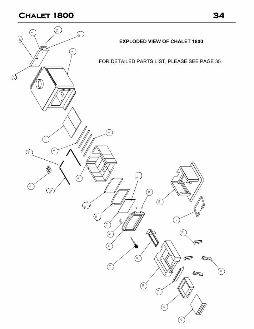
EXPLODED VIEW OF CHALET 1800
FOR DETAILED PARTS LIST, PLEASE SEE PAGE 35
11
10
9
7B
7A
27
29
28
26

Chalet 1800 35
PARTS LIST FOR CHALET 1800
NUMBER PART NO. DESCRIPTION
10-1800 FREESTANDING CHALET 1800 WOODSTOVE FIREBOX ONLY (ALL OTHER COMPONENTS
MUST BE ADDED SEPARATELY)
OPTIONAL ITEMS
1 15-1700 FAN KIT FOR CHALET WOODSTOVES
2 10-1800 FIREBOX ONLY FOR CHALET 1800 FS
3 311-0080 FIBRE BAFFLE (SET OF 2)
4 317-0059 SECONDARY REAR AIR TUBE
5 317-0060 SECONDARY FRONT AIR TUBE
6 325-0003 ASH PLUG
7A 780-0063 BRICK RETAINER, SIDE, FOR 1800 (REQUIRES 2)
7B 780-0062 BRICK RETAINER, REAR
8 FIRE BRICKS (REFERE TO PG. 15 FOR REQUIRED BRICK #)
9 314-0021 GLASS GASKET 3/4 GRAPHITE FLAT FIBREGLASS GASKET
10 780-0034 GLASS RETAINER
11 314-0020 DOOR GASKET, 3/4” ROPE, BLACK (GRAPHITE) HIGH DENSITY
12 307-0057 REPLACEMENT GLASS 14.5 X 8.875 PYROCERAM III
13 880-0003 DOOR HANDLE ASSEMBLY WITH HARDWARE (WITHOUT SPRING HANDLE)
14 15-0201
15-0202
15-0203
CAST IRON DOOR, BLACK (INCLUDES BRASS SPRING HANDLE)
CAST IRON DOOR, GOLD (INCLUDES BRASS SPRING HANDLE)
CAST IRON DOOR, NICKEL (INCLUES NICKEL PLATED SPRING HANDLE)
15 300-2005 DECORATIVE HINGE BUTTONS (SET OF 2)
16 300-2001
300-2016
BRASS SPRING DOOR HANDLE FOR CHALET ~ 1/2”
NICKEL PLATED SPRING DOOR HANDLE FOR CHALET ~ 1/2”
17 10-0600 FRESH AIR ADAPTER
18 10-0101 SKIRT, BLACK FOR CHALET 1800 FS (LEGS NOT INCLUDED)
19 780-0052 LEG SHIELD DOOR FOR CHALET WOODSTOVES
20 15-0001 PEDESTAL FOR CHALET 1800 FS (INCLUDES ASH PAN)
21 780-0042 PEDESTAL DOOR FOR CHALET WOODSTOVES
22 AND 23 15-0301
15-0302
15-0303
LEGS, BLACK FOR CHALET FS (SET OF 4)
LEGS, GOLD FOR CHALET FS (SET OF 4)
LEGS, NICKEL PLATED FOR CHALET FS (SET OF 4)
24 880-0001 ASH DRAWER KIT (INCLUDES ASH DRAWER COVER)
25 780-0032 ASH DRAWER COVER
26 305-0012 POWER CORD (120 VAC)
27 305-0021 THERMODISC 110ºF
28 305-0013 SOLID STATE SPEED CONTROL
29 305-0024 REPLACEMENT BLOWER FOR 15-1700 (150 CFM, 115 VAC)

Chalet 1800 36
This Limited Warranty is made by ARCHGARD INDUSTRIES LTD., hereinafter referred to as “Archgard”. Archgard warrants to the
original purchaser of an Archgard Wood burning fireplace (s) that the product will be free of defects in materials and workmanship under
normal use and service, for a “lifetime”.
INCLUSIONS: “LIFETIME LIMITED WARRANTY”
❖ All combustion chamber and air tubes. (against warpage)
❖ Ceramic Brick Panels against splitting or cracking.
❖ Ceramic Glass against thermal breakage.
❖ All 24 K gold trims and accessories against defective manufacturing
❖ NOTE: Discoloration and some minor movement of certain parts are normal and are not a defect and therefore, not covered under war-ranty.
The above will be covered “parts & subsidized labor” to the original purchaser for FIVE years and “parts” only thereafter from original
date of purchase.
Special Finishes—One year on brushed nickel louvers and doors. You can expect some changes in color as the product “ages” with
constant heating and cooling. Archgard warranties the product for any manufacturing defects on the original product. However, the
manufacturers warranty does not cover changing colors and marks, ie: finger prints etc applied after the purchase of the product. Damage
from the use of abrasive cleaners is not covered by warranty
INCLUSIONS: “ONE YEAR LIMITED WARRANTY”
❖ Blowers, fans and fan motors, wiring, rheostats and thermodiscs.
❖ Rocker switches and wiring to them.
The above will be covered “parts & subsidized labor” to the original purchaser for ONE year from date of purchase.
EXCLUSIONS: “1 YEAR AND 5 YEAR LIMITED WARRANTY”
❖ Archgard does not offer warranty on damages to fireplace mantel (s), trims or tiles.
❖ Travel time or mileage to original purchasers residence. Archgard suggests that you pre-arrange travel expenses with your Authorized Archgard Dealer.
❖ Door Latch Hardware, paint, gasketing, firebrick or trim.
❖ This warranty does not cover installation and operational related problems such as over-firing, use of corrosive driftwood, downdrafts or spillage caused by environmental conditions, nearby trees, buildings, hill tops, mountains, inadequate venting or ventilation, exces-sive offsets, negative air pressures caused by mechanical systems such as furnaces, fans, clothes dryers, etc.
WHAT TO DO IN THE EVENT OF A PROBLEM:
❖ Thoroughly read your manual.
❖ If you cannot solve the problem, contact your Archgard Dealer or representative.
❖ When calling for help please have the following information:
Model of your Fireplace Serial Number Place of Purchase
Date of Purchase Problem Description
❖ NOTE: Warranty may be void if work is carried out by an unqualified person (s). Only original Archgard parts may be used. Please consult your Archgard dealer or representative if in doubt about a replacement part (s).
OBTAINING WARRANTY SERVICE:
To obtain warranty service, the original purchaser shall return the defective part (s) to the original authorized Archgard selling dealer trans-
portation prepaid, along with the serial number of the appliance and proof of purchase. Any defective part, in our
judgment, will be repaired or replaced at Archgard’s discretion. The dealer must obtain approval from Archgard before any
repairs are made.
* Subsidy according to job scale as predetermined by Archgard Industries Ltd.
ARCHGARDARCHGARD LIMITED WARRANTYLIMITED WARRANTY

Chalet 1800 37
WARRANTY LIMITATION:
THIS LIMITED WARRANTY IS MADE IN LIEU OF ALL OTHER WARRANTIES, EXPRESSED OR IMPLIED AS TO QUALITY, MER-
CHANTABILITY OR FITNESS FOR PARTICULAR PURPOSE.
Archgard is not liable for freight or labor on any wood burning appliance replaced in the field. Any part or parts of this unit which in our judg-
ment show evidence of such defects will be repaired or replaced at Archgard’s option, through an accredited dealer or Agent provided that the
defective part be returned to the dealer or agent Transportation Prepaid, if requested. The appliance is only warranted for the use as intended by
the installation and operating instruction and local building codes. The warranty will not cover damage due to accident, misuse, abuse, alteration,
improper installation or “Acts Of God”, “Act of Terrorism” or Shipping.
Installation and environmental problems are not the responsibility of the manufacturer and therefore are not covered under the terms of this
warranty.
Performance problems due to operator error will not be covered by this warranty policy.
Products made or provided by other manufacturers and used in conjunction with the operation of the appliance without prior authorization from
Archgard Industries may nullify your warranty on this product
This limited warranty is void unless the appliance is installed by a qualified installer, in accordance with the instructions furnished with the appli-
ance. Some Provinces or States do not allow limitations on how long an implied warranty lasts, so the above limitation may not apply to the origi-
nal purchaser. Any damage resulting from defects in this product, is limited to the
replacement of the defective part (s) and does not include incidental and consequential exposures sustained in connection with the product. This
includes facing (s), mantle (s), cabinet (s), tile (s) or any other finishes resulting from removal of any gas appliance. This warranty is limited to
residential use only and gives the consumer specific rights. These rights may vary from State to State or Province to Province.
LIMITED WARRANTY CONT’DLIMITED WARRANTY CONT’D
POSTAGE
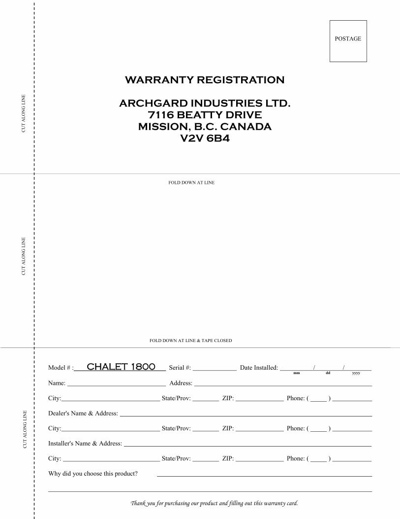
WARRANTY REGISTRATION
ARCHGARD INDUSTRIES LTD.
7116 BEATTY DRIVE
MISSION, B.C. CANADA
V2V 6B4
FOLD DOWN AT LINE
FOLD DOWN AT LINE & TAPE CLOSED
CU
T A
LO
NG
LIN
E
CU
T A
LO
NG
LIN
E
CU
T A
LO
NG
LIN
E
Model # : CHALET 1800 Serial #: Date Installed: / /
Name: Address:
City: State/Prov: ZIP: Phone: ( _____ )
Dealer's Name & Address:
City: State/Prov: ZIP: Phone: ( _____ )
Installer's Name & Address:
City: State/Prov: ZIP: Phone: ( _____ )
Why did you choose this product?
Thank you for purchasing our product and filling out this warranty card.
mm dd yyyy

Archgard Industries Ltd.
7116 Beatty Drive
Mission, B.C. V2V 6B4
Canada
Website: www.archgard.com

Fireplace Model Number: CHALET 1800 Serial Number: Date of Installation: Dealer’s Name & Address:
Dealer’s Phone Number:
Archgard fireplace products are designed with reliability and simplicity in mind. In addition, our internal Quality Assurance Team carefully inspects each unit thor-oughly before it leaves our door. Archgard is pleased to extend this Limited Life-
time Warranty to the original purchaser of an Archgard Product. See page 36 for details.
We recommend you record the following information: