ch 4b foundation engineeringbartlett/cveen5305/ch. 4b - stress, strain... · ch 4b foundation...
TRANSCRIPT
© Steven F. Bartlett, 2011
Ch. 4b Lecture Notes○
Sections 4.4 - 4.8 (Salgado)○
Reading Assignment
none○
Other Materials
Problems 4-18, 4-19, 4-21, 4-22, 4-23, 4-25, 4-28 part c only○
Homework Assignment 4
Ch 4b Foundation EngineeringWednesday, August 17, 2011 12:45 PM
Ch. 4b - Stress, Strain, Shearing Page 1
© Steven F. Bartlett, 2011
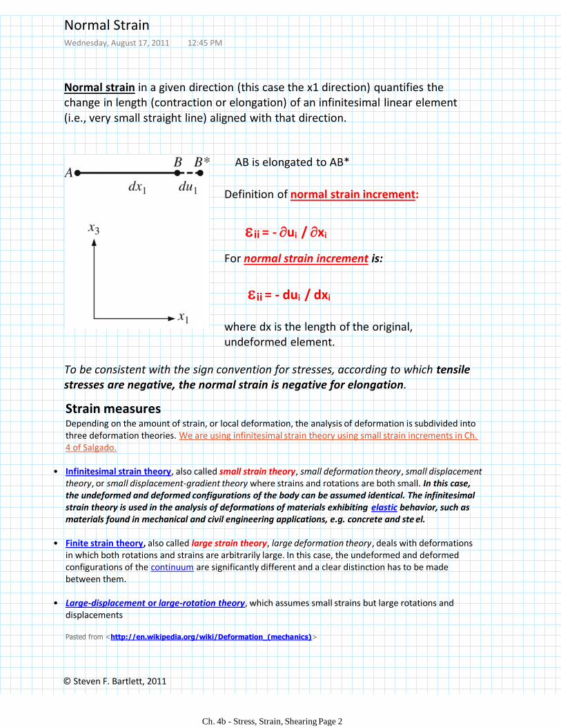
Normal strain in a given direction (this case the x1 direction) quantifies the change in length (contraction or elongation) of an infinitesimal linear element (i.e., very small straight line) aligned with that direction.
ii = - ui / xi
AB is elongated to AB*
Definition of normal strain increment:
To be consistent with the sign convention for stresses, according to which tensile stresses are negative, the normal strain is negative for elongation.
Strain measuresDepending on the amount of strain, or local deformation, the analysis of deformation is subdivided into three deformation theories. We are using infinitesimal strain theory using small strain increments in Ch. 4 of Salgado.
Infinitesimal strain theory, also called small strain theory, small deformation theory, small displacement theory, or small displacement-gradient theory where strains and rotations are both small. In this case, the undeformed and deformed configurations of the body can be assumed identical. The infinitesimal strain theory is used in the analysis of deformations of materials exhibiting elastic behavior, such as materials found in mechanical and civil engineering applications, e.g. concrete and ste el.
•
Finite strain theory, also called large strain theory, large deformation theory, deals with deformations in which both rotations and strains are arbitrarily large. In this case, the undeformed and deformed configurations of the continuum are significantly different and a clear distinction has to be made between them.
•
Large-displacement or large-rotation theory, which assumes small strains but large rotations and displacements
•
Pasted from <http://en.wikipedia.org/wiki/Deformation_(mechanics)>
For normal strain increment is:
ii = - dui / dxi
where dx is the length of the original, undeformed element.
Normal StrainWednesday, August 17, 2011 12:45 PM
Ch. 4b - Stress, Strain, Shearing Page 2
© Steven F. Bartlett, 2011
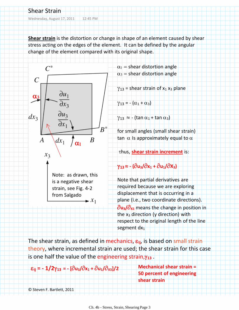
Shear strain is the distortion or change in shape of an element caused by shear stress acting on the edges of the element. It can be defined by the angular change of the element compared with its original shape.
shear distortion angle
shear distortion angle
13 = shear strain of x1 x3 plane
13 = - (1 + 3)
13 ≈ - (tan 1 + tan 3)
for small angles (small shear strain)
tan Is approximately equal to
hus, shear strain increment is:
13≈ - (u3/x1 + u1/X3)
Note that partial derivatives are required because we are exploring displacement that is occurring in a plane (i.e., two coordinate directions).
u3/X1 means the change in position in the x3 direction (y direction) with respect to the original length of the line segment dx1
The shear strain, as defined in mechanics, Ij, is based on small strain theory, where incremental strain are used; the shear strain for this case
is one half the value of the engineering strain,13 .
ij = - 1/213 = - [u3/x1 + u1/X3]/2
Note: as drawn, this is a negative shear strain, see Fig. 4-2 from Salgado
Mechanical shear strain = 50 percent of engineering shear strain
Shear StrainWednesday, August 17, 2011 12:45 PM
Ch. 4b - Stress, Strain, Shearing Page 3
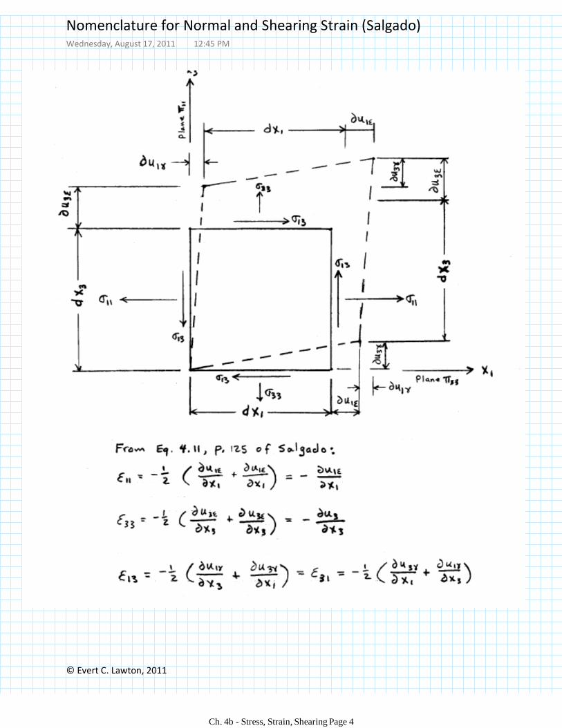
© Evert C. Lawton, 2011
Nomenclature for Normal and Shearing Strain (Salgado)Wednesday, August 17, 2011 12:45 PM
Ch. 4b - Stress, Strain, Shearing Page 4
© Steven F. Bartlett, 2017
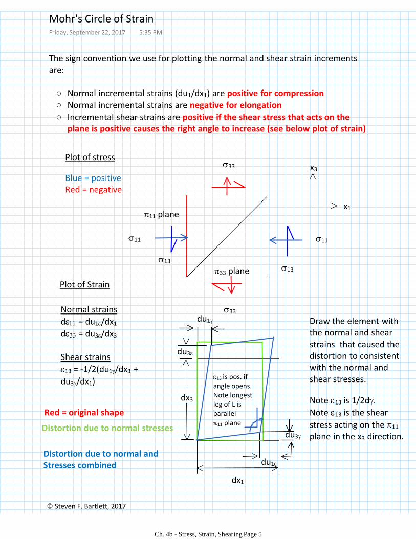
The sign convention we use for plotting the normal and shear strain increments are:
Normal incremental strains (du1/dx1) are positive for compression○
Normal incremental strains are negative for elongation○
Incremental shear strains are positive if the shear stress that acts on the plane is positive causes the right angle to increase (see below plot of strain)
○
Draw the element with the normal and shear strains that caused the distortion to consistent with the normal and shear stresses.
Note 13 is 1/2d
Note 13 is the shear
stress acting on the 11
plane in the x3 direction.
x1
x3
dx1
Plot of Strain
du1
Distortion due to normal stresses
Distortion due to normal andStresses combined
11 plane
33 plane
Plot of stress
Blue = positiveRed = negative
11
33
13
Red = original shape
du3
Normal strains
d = du1/dx1
d = du3/dx3
Shear strains
13 = -1/2(du1/dx3 +
du3/dx1)
dx3
13 is pos. if angle opens. Note longest leg of L is parallel
11 plane
33
11
13
du1
du3
Mohr's Circle of Strain Friday, September 22, 2017 5:35 PM
Ch. 4b - Stress, Strain, Shearing Page 5
© Steven F. Bartlett, 2017
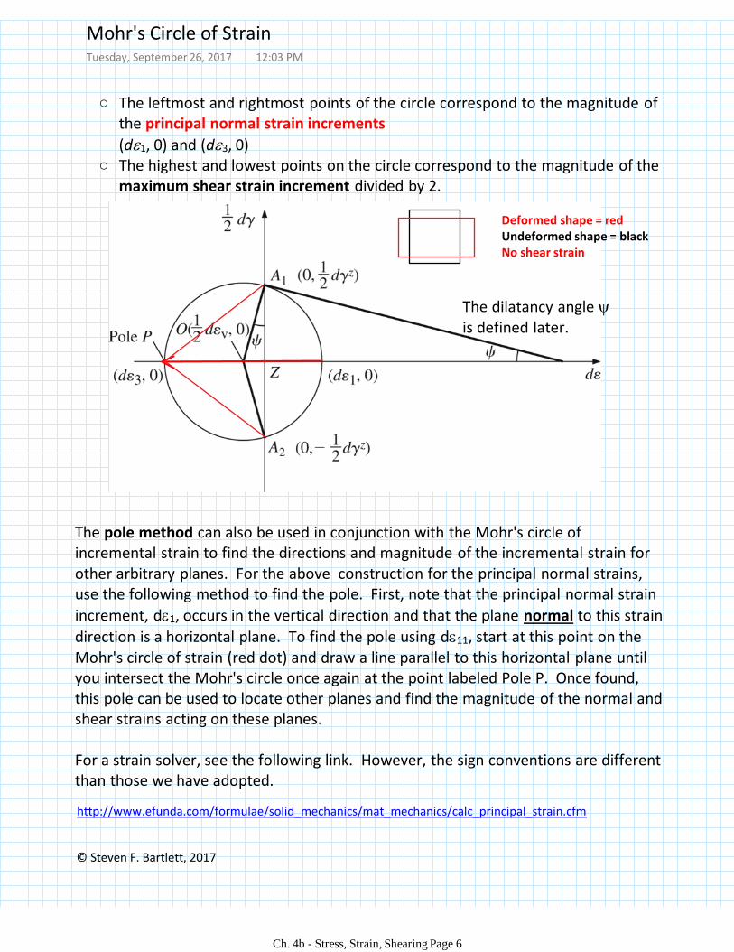
The leftmost and rightmost points of the circle correspond to the magnitude of the principal normal strain increments
○
(d1, 0) and (d3, 0)The highest and lowest points on the circle correspond to the magnitude of the maximum shear strain increment divided by 2.
○
The pole method can also be used in conjunction with the Mohr's circle of incremental strain to find the directions and magnitude of the incremental strain for other arbitrary planes. For the above construction for the principal normal strains, use the following method to find the pole. First, note that the principal normal strain
increment, d1, occurs in the vertical direction and that the plane normal to this strain
direction is a horizontal plane. To find the pole using d11, start at this point on the Mohr's circle of strain (red dot) and draw a line parallel to this horizontal plane until you intersect the Mohr's circle once again at the point labeled Pole P. Once found, this pole can be used to locate other planes and find the magnitude of the normal and shear strains acting on these planes.
For a strain solver, see the following link. However, the sign conventions are different than those we have adopted.
http://www.efunda.com/formulae/solid_mechanics/mat_mechanics/calc_principal_strain.cfm
The dilatancy angle is defined later.
Deformed shape = redUndeformed shape = blackNo shear strain
Mohr's Circle of StrainTuesday, September 26, 2017 12:03 PM
Ch. 4b - Stress, Strain, Shearing Page 6
© Steven F. Bartlett, 2017
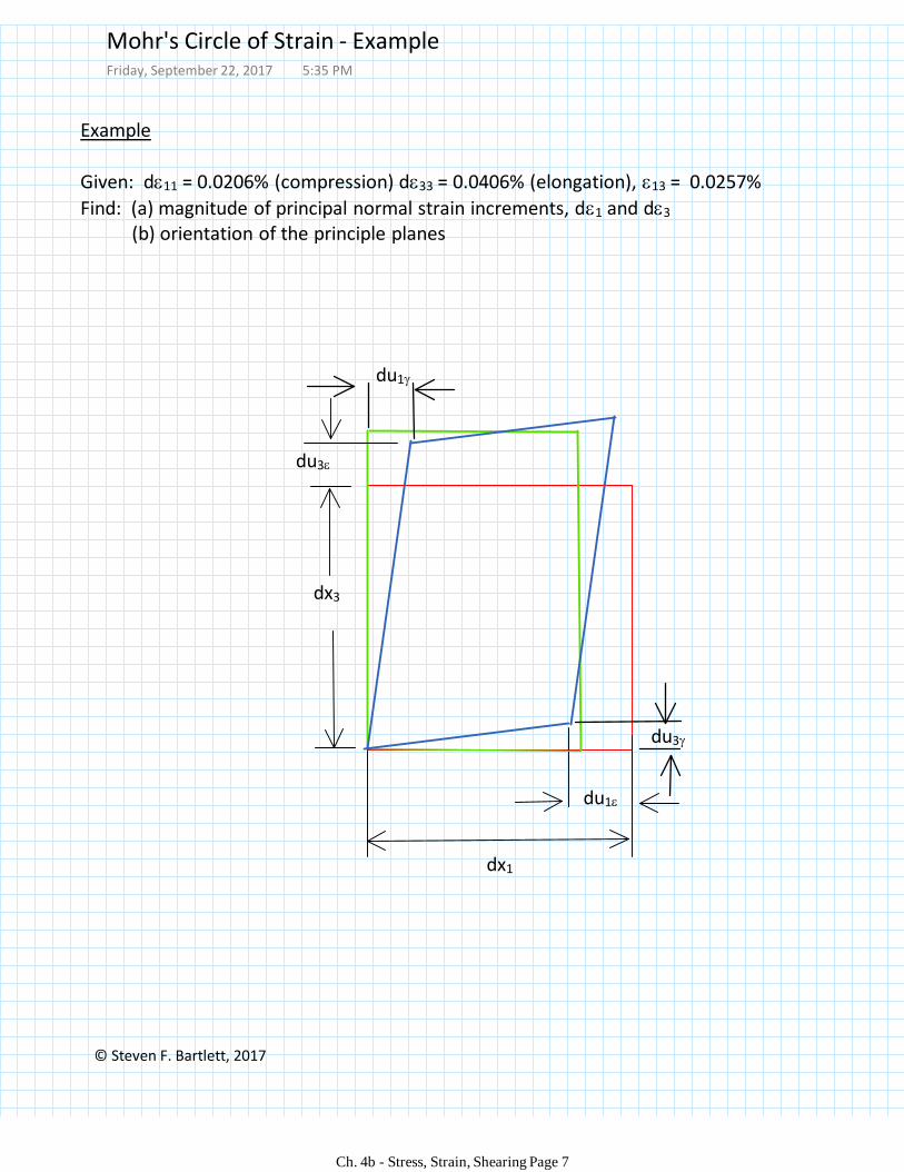
Example
Given: d11 = 0.0206% (compression) d33 = 0.0406% (elongation), 13 = 0.0257%
Find: (a) magnitude of principal normal strain increments, d1 and d3
(b) orientation of the principle planes
dx1
du1
du3
dx3
du1
du3
Mohr's Circle of Strain - ExampleFriday, September 22, 2017 5:35 PM
Ch. 4b - Stress, Strain, Shearing Page 7
© Steven F. Bartlett, 2017
d
1/2d
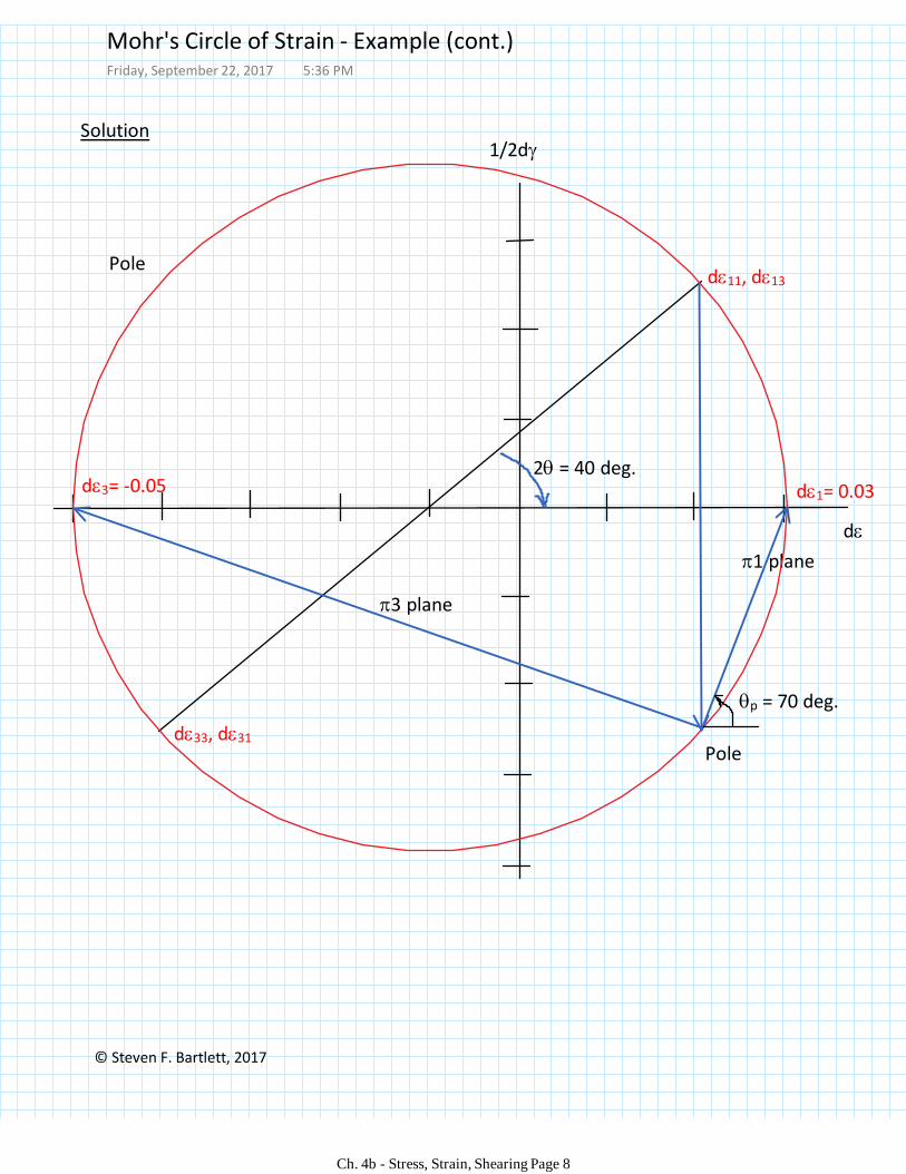
d11, d13
d33, d31
Pole
d1= 0.03d3= -0.052 = 40 deg.
p = 70 deg.
Solution
Pole
1 plane
3 plane
Mohr's Circle of Strain - Example (cont.)Friday, September 22, 2017 5:36 PM
Ch. 4b - Stress, Strain, Shearing Page 8
© Steven F. Bartlett, 2017
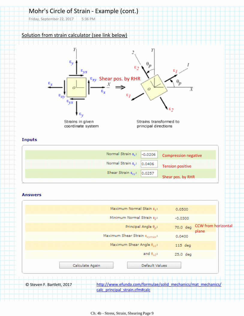
Solution from strain calculator (see link below)
http://www.efunda.com/formulae/solid_mechanics/mat_mechanics/calc_principal_strain.cfm#calc
Compression negative
Tension positive
Shear pos. by RHR
Shear pos. by RHR
CCW from horizontal plane
Mohr's Circle of Strain - Example (cont.)Friday, September 22, 2017 5:36 PM
Ch. 4b - Stress, Strain, Shearing Page 9
© Steven F. Bartlett, 2011
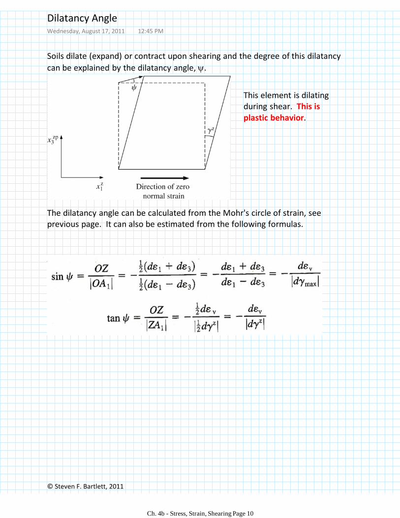
Soils dilate (expand) or contract upon shearing and the degree of this dilatancy
can be explained by the dilatancy angle, .
The dilatancy angle can be calculated from the Mohr's circle of strain, see previous page. It can also be estimated from the following formulas.
This element is dilating during shear. This is plastic behavior.
Dilatancy AngleWednesday, August 17, 2011 12:45 PM
Ch. 4b - Stress, Strain, Shearing Page 10
© Steven Bartlett, 2011
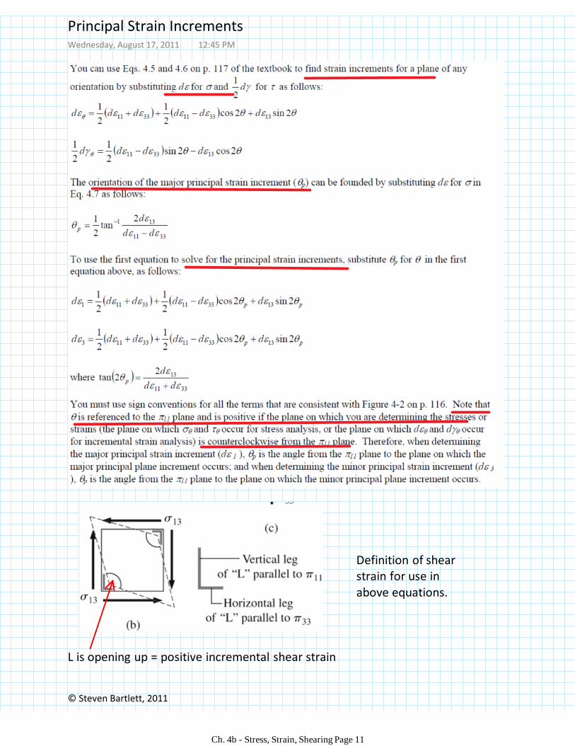
Definition of shear strain for use in above equations.
L is opening up = positive incremental shear strain
Principal Strain IncrementsWednesday, August 17, 2011 12:45 PM
Ch. 4b - Stress, Strain, Shearing Page 11
© Steven F. Bartlett, 2011
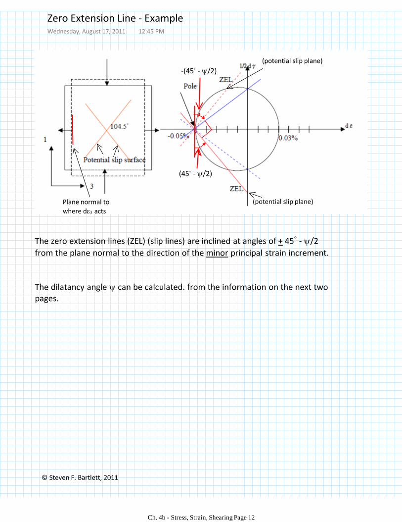
The zero extension lines (ZEL) (slip lines) are inclined at angles of + 45◦ - /2
from the plane normal to the direction of the minor principal strain increment.
The dilatancy angle can be calculated. from the information on the next two pages.
Plane normal to
where d acts
(potential slip plane)
(potential slip plane)
(45◦ - /2)
-(45◦ - /2)
Zero Extension Line - ExampleWednesday, August 17, 2011 12:45 PM
Ch. 4b - Stress, Strain, Shearing Page 12
© Steven F. Bartlett, 2011
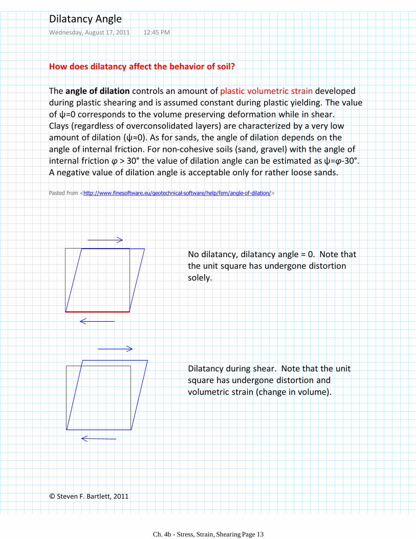
The angle of dilation controls an amount of plastic volumetric strain developed during plastic shearing and is assumed constant during plastic yielding. The value of ψ=0 corresponds to the volume preserving deformation while in shear.Clays (regardless of overconsolidated layers) are characterized by a very low amount of dilation (ψ≈0). As for sands, the angle of dilation depends on the angle of internal friction. For non-cohesive soils (sand, gravel) with the angle of internal friction φ > 30° the value of dilation angle can be estimated as ψ=φ-30°. A negative value of dilation angle is acceptable only for rather loose sands.
Pasted from <http://www.finesoftware.eu/geotechnical-software/help/fem/angle-of-dilation/>
How does dilatancy affect the behavior of soil?
No dilatancy, dilatancy angle = 0. Note that the unit square has undergone distortion solely.
Dilatancy during shear. Note that the unit square has undergone distortion and volumetric strain (change in volume).
Dilatancy AngleWednesday, August 17, 2011 12:45 PM
Ch. 4b - Stress, Strain, Shearing Page 13
© Steven F. Bartlett, 2011
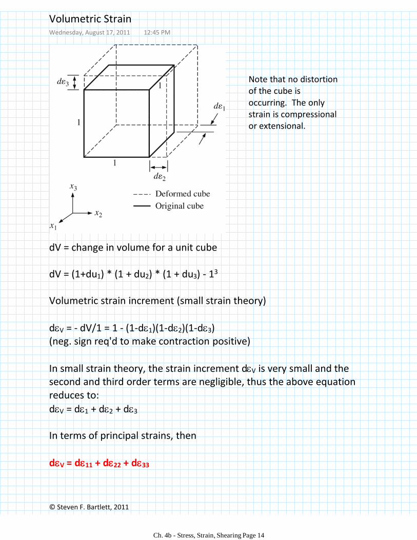
dV = change in volume for a unit cube
dV = (1+du1) * (1 + du2) * (1 + du3) - 13
Volumetric strain increment (small strain theory)
dV = - dV/1 = 1 - (1-d1)(1-d2)(1-d3) (neg. sign req'd to make contraction positive)
In small strain theory, the strain increment dV is very small and the second and third order terms are negligible, thus the above equation reduces to:
dV = d1 + d2 + d3
In terms of principal strains, then
dV = d11 + d22 + d33
Note that no distortion of the cube is occurring. The only strain is compressional or extensional.
Volumetric StrainWednesday, August 17, 2011 12:45 PM
Ch. 4b - Stress, Strain, Shearing Page 14
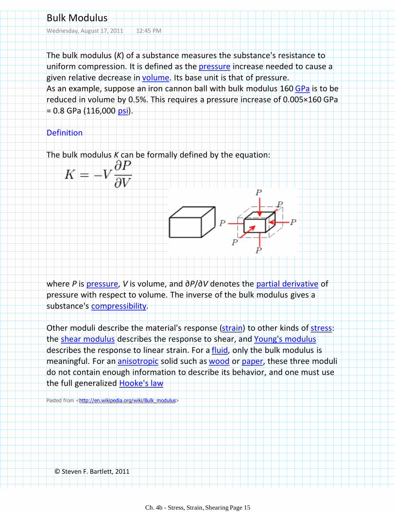
The bulk modulus (K) of a substance measures the substance's resistance to uniform compression. It is defined as the pressure increase needed to cause a given relative decrease in volume. Its base unit is that of pressure.As an example, suppose an iron cannon ball with bulk modulus 160 GPa is to be reduced in volume by 0.5%. This requires a pressure increase of 0.005×160 GPa = 0.8 GPa (116,000 psi).
Definition
The bulk modulus K can be formally defined by the equation:
where P is pressure, V is volume, and ∂P/∂V denotes the partial derivative of pressure with respect to volume. The inverse of the bulk modulus gives a substance's compressibility.
Other moduli describe the material's response (strain) to other kinds of stress: the shear modulus describes the response to shear, and Young's modulusdescribes the response to linear strain. For a fluid, only the bulk modulus is meaningful. For an anisotropic solid such as wood or paper, these three moduli do not contain enough information to describe its behavior, and one must use the full generalized Hooke's law
Pasted from <http://en.wikipedia.org/wiki/Bulk_modulus>
© Steven F. Bartlett, 2011
Bulk ModulusWednesday, August 17, 2011 12:45 PM
Ch. 4b - Stress, Strain, Shearing Page 15
Steven F. Bartlett, 2011
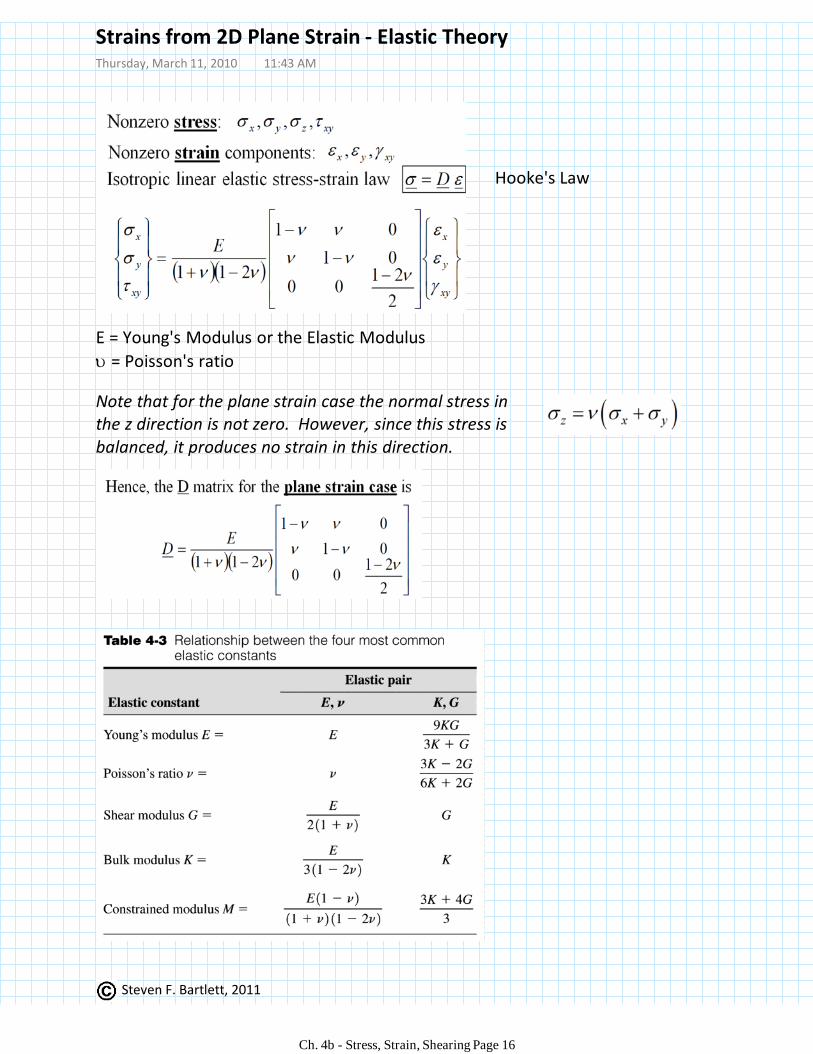
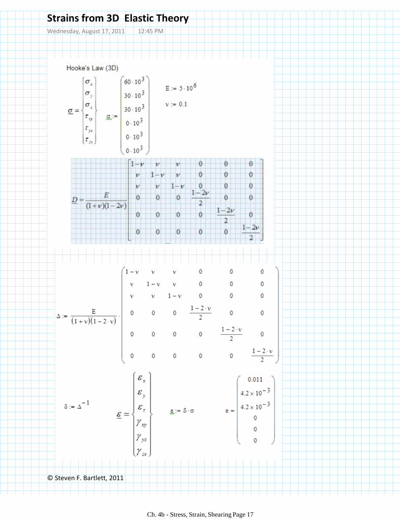
Note that for the plane strain case the normal stress in the z direction is not zero. However, since this stress is balanced, it produces no strain in this direction.
Hooke's Law
E = Young's Modulus or the Elastic Modulus
= Poisson's ratio
Strains from 2D Plane Strain - Elastic TheoryThursday, March 11, 2010 11:43 AM
Ch. 4b - Stress, Strain, Shearing Page 16
© Steven F. Bartlett, 2011
Strains from 3D Elastic TheoryWednesday, August 17, 2011 12:45 PM
Ch. 4b - Stress, Strain, Shearing Page 17
© Steven F. Bartlett, 2011
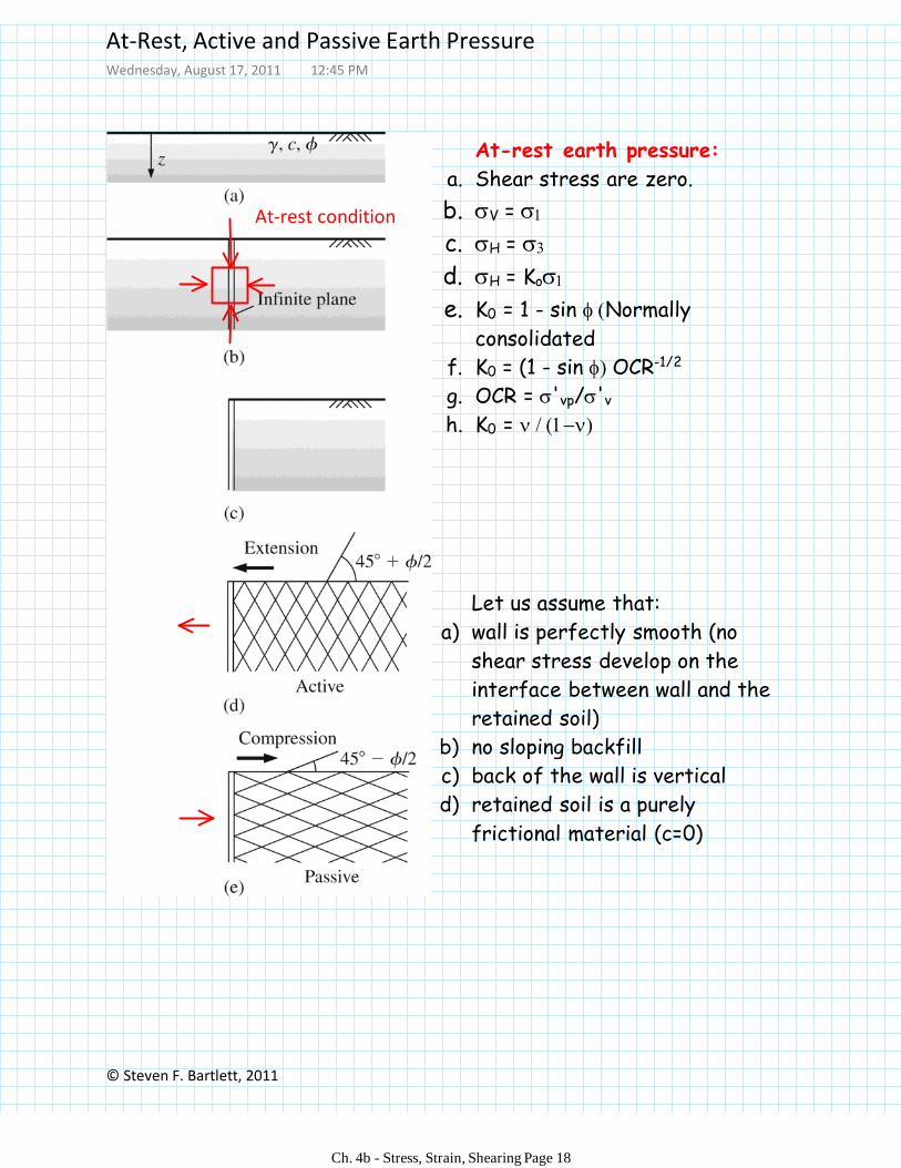
Let us assume that:
wall is perfectly smooth (no
shear stress develop on the
interface between wall and the
retained soil)
a)
no sloping backfillb)
back of the wall is verticalc)
retained soil is a purely
frictional material (c=0)
d)
At-rest earth pressure:
Shear stress are zero.a.
V = b.
H = c.
H = Kod.
K0 = 1 - sin Normally
consolidated
e.
K0 = (1 - sin OCR-1/2f.
OCR = 'vp/'vg.
K0 = h.
At-rest condition
At-Rest, Active and Passive Earth PressureWednesday, August 17, 2011 12:45 PM
Ch. 4b - Stress, Strain, Shearing Page 18
© Steven F. Bartlett, 2011
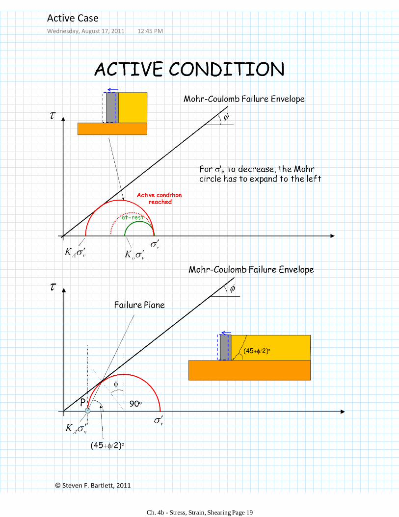
Active CaseWednesday, August 17, 2011 12:45 PM
Ch. 4b - Stress, Strain, Shearing Page 19
© Steven F. Bartlett, 2011
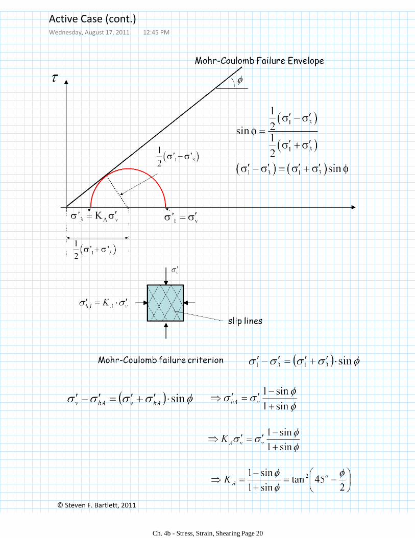
Active Case (cont.)Wednesday, August 17, 2011 12:45 PM
Ch. 4b - Stress, Strain, Shearing Page 20
Vc b
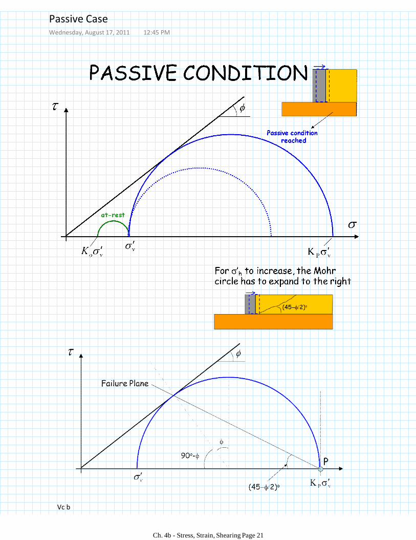
Passive CaseWednesday, August 17, 2011 12:45 PM
Ch. 4b - Stress, Strain, Shearing Page 21
© Steven F. Bartlett, 2011
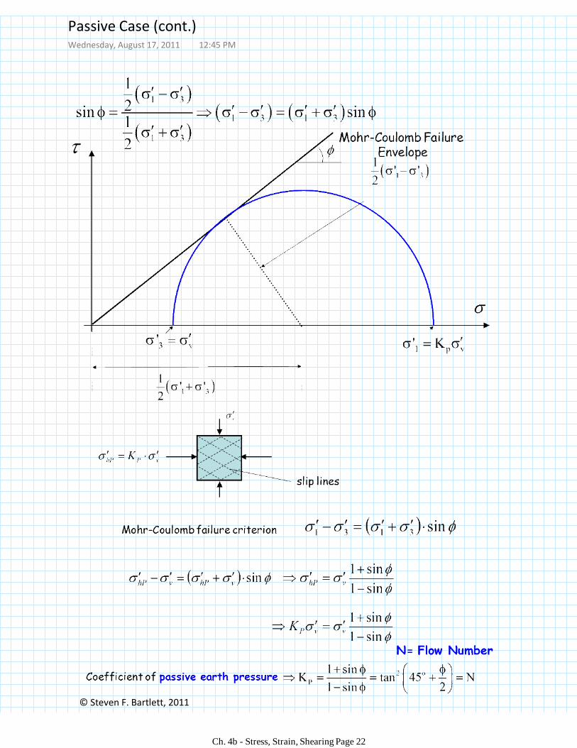
Passive Case (cont.)Wednesday, August 17, 2011 12:45 PM
Ch. 4b - Stress, Strain, Shearing Page 22
© Steven F. Bartlett, 2011
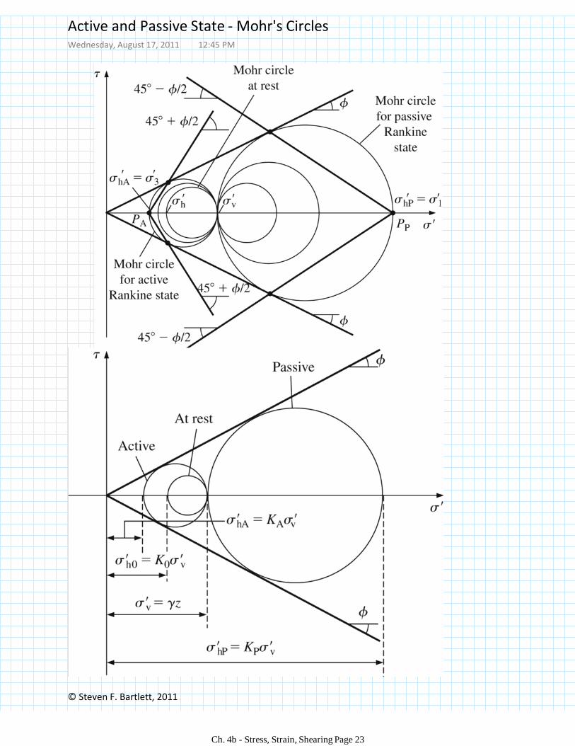
Active and Passive State - Mohr's CirclesWednesday, August 17, 2011 12:45 PM
Ch. 4b - Stress, Strain, Shearing Page 23
© Steven F. Bartlett, 2011
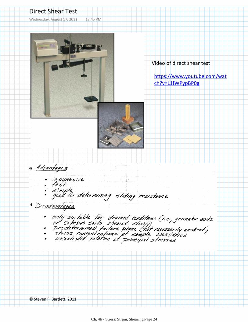
https://www.youtube.com/watch?v=L1fWPypBP0g
Video of direct shear test
Direct Shear TestWednesday, August 17, 2011 12:45 PM
Ch. 4b - Stress, Strain, Shearing Page 24
© Steven F. Bartlett, 2011
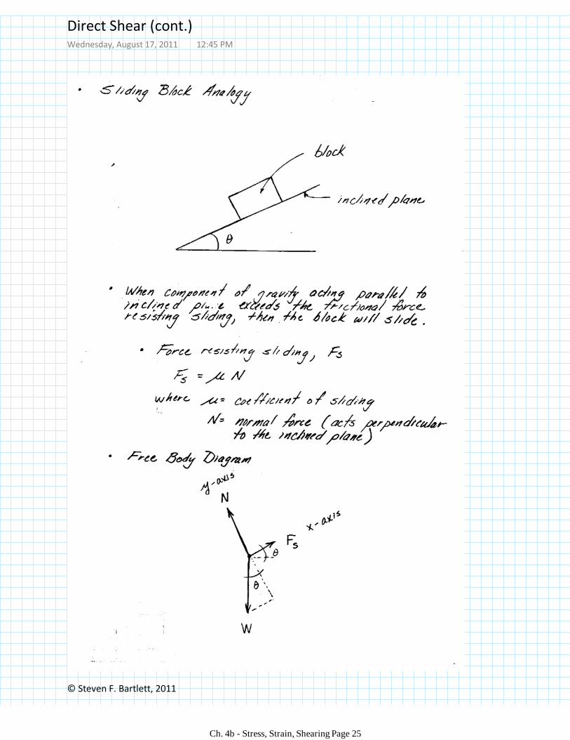
Direct Shear (cont.)Wednesday, August 17, 2011 12:45 PM
Ch. 4b - Stress, Strain, Shearing Page 25
© Steven F. Bartlett, 2011
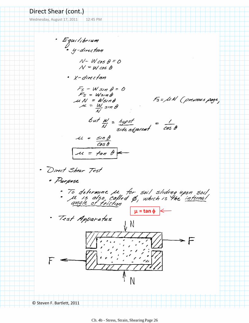
= tan
Direct Shear (cont.)Wednesday, August 17, 2011 12:45 PM
Ch. 4b - Stress, Strain, Shearing Page 26
© Steven F. Bartlett, 2011
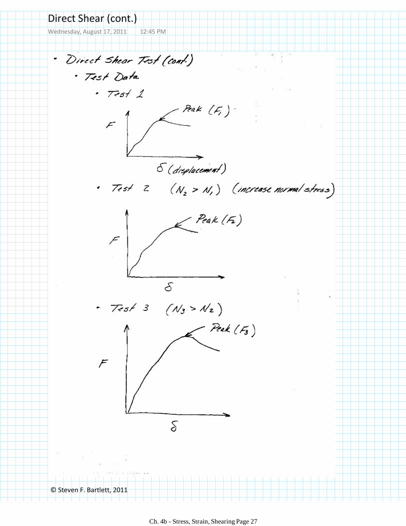
Direct Shear (cont.)Wednesday, August 17, 2011 12:45 PM
Ch. 4b - Stress, Strain, Shearing Page 27
© Steven F. Bartlett, 2011
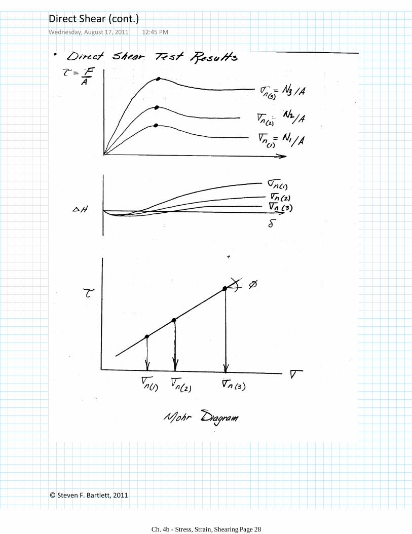
Direct Shear (cont.)Wednesday, August 17, 2011 12:45 PM
Ch. 4b - Stress, Strain, Shearing Page 28
© Steven F. Bartlett, 2011
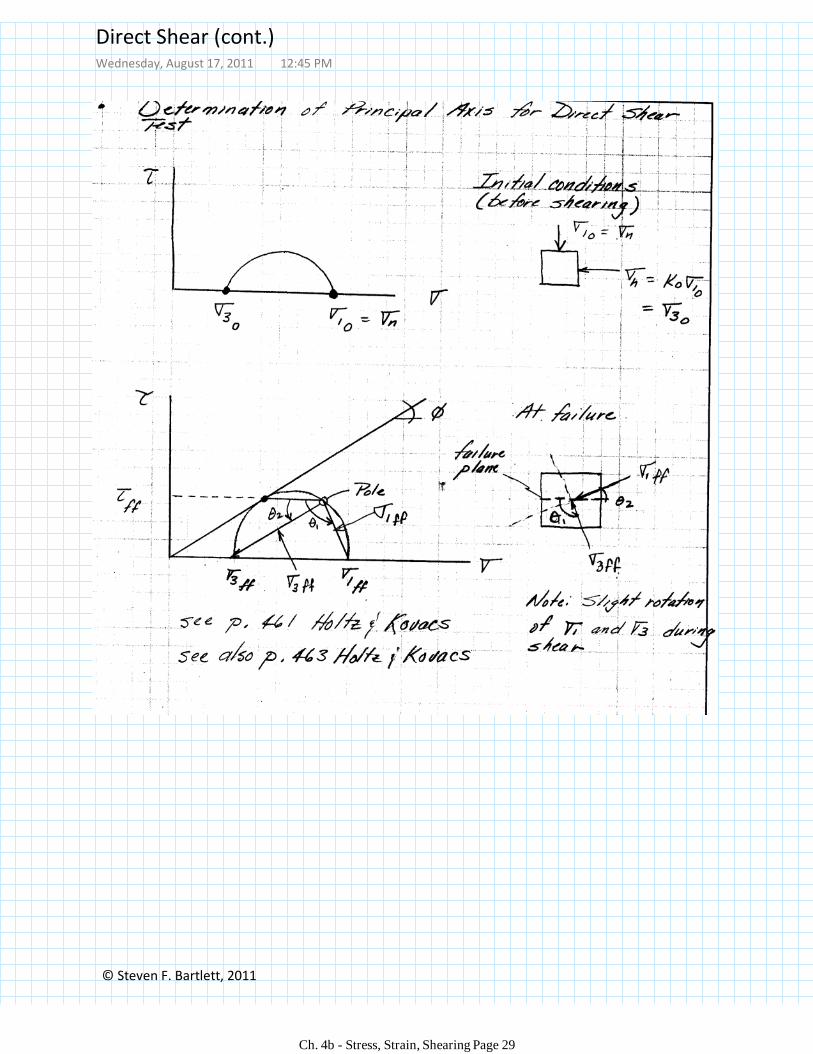
Direct Shear (cont.)Wednesday, August 17, 2011 12:45 PM
Ch. 4b - Stress, Strain, Shearing Page 29
© Steven F. Bartlett, 2011
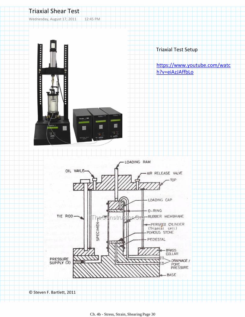
https://www.youtube.com/watch?v=eiAzJAffbLo
Triaxial Test Setup
Triaxial Shear TestWednesday, August 17, 2011 12:45 PM
Ch. 4b - Stress, Strain, Shearing Page 30
© Steven F. Bartlett, 2011
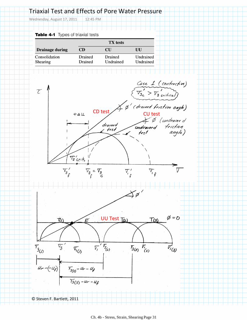
CD test CU test
UU Test
Triaxial Test and Effects of Pore Water PressureWednesday, August 17, 2011 12:45 PM
Ch. 4b - Stress, Strain, Shearing Page 31
© Steven F. Bartlett, 2011
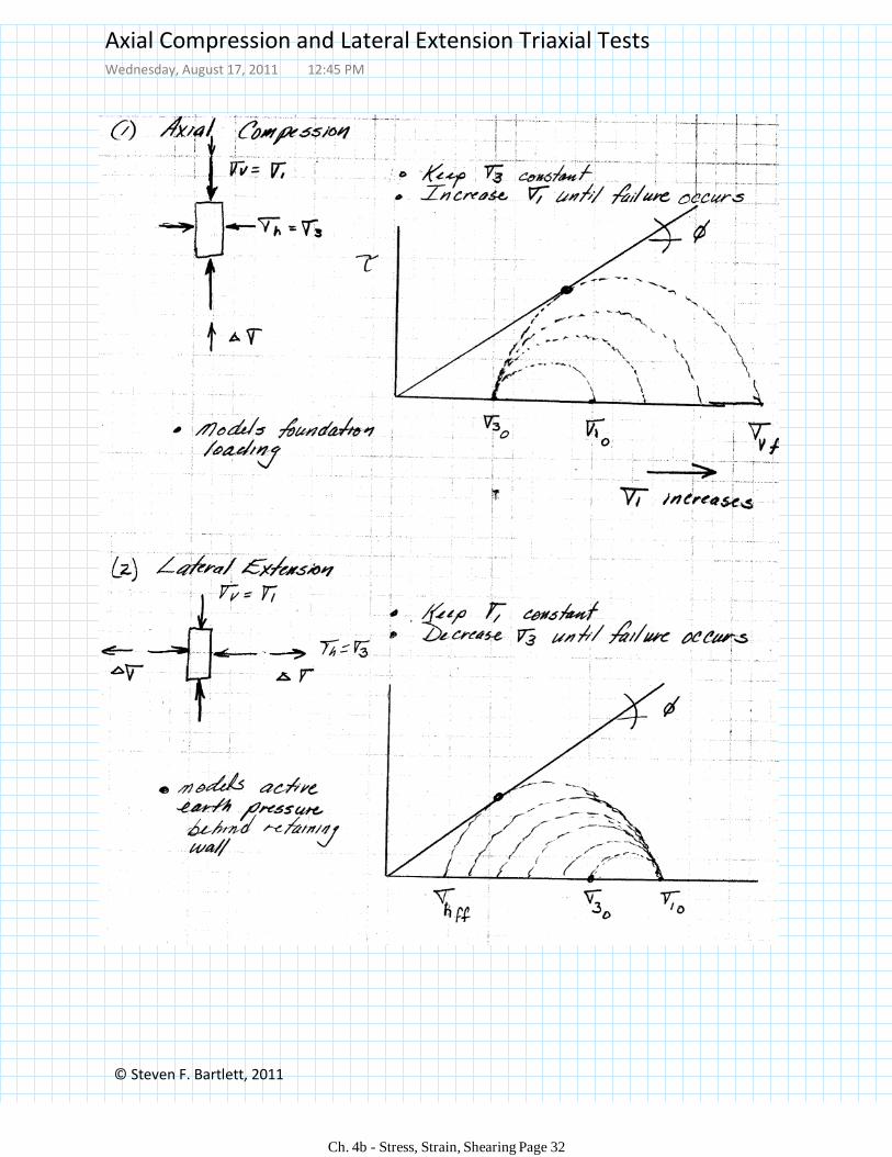
Axial Compression and Lateral Extension Triaxial TestsWednesday, August 17, 2011 12:45 PM
Ch. 4b - Stress, Strain, Shearing Page 32
© Steven F. Bartlett, 2011
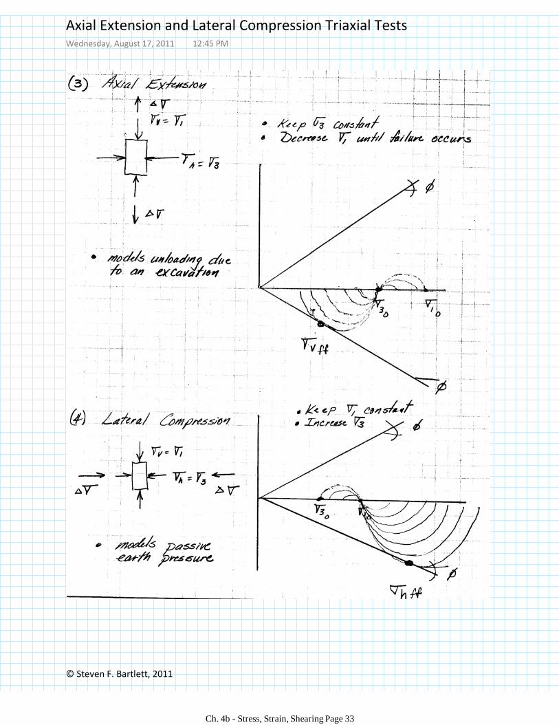
Axial Extension and Lateral Compression Triaxial TestsWednesday, August 17, 2011 12:45 PM
Ch. 4b - Stress, Strain, Shearing Page 33
© Steven F. Bartlett, 2011
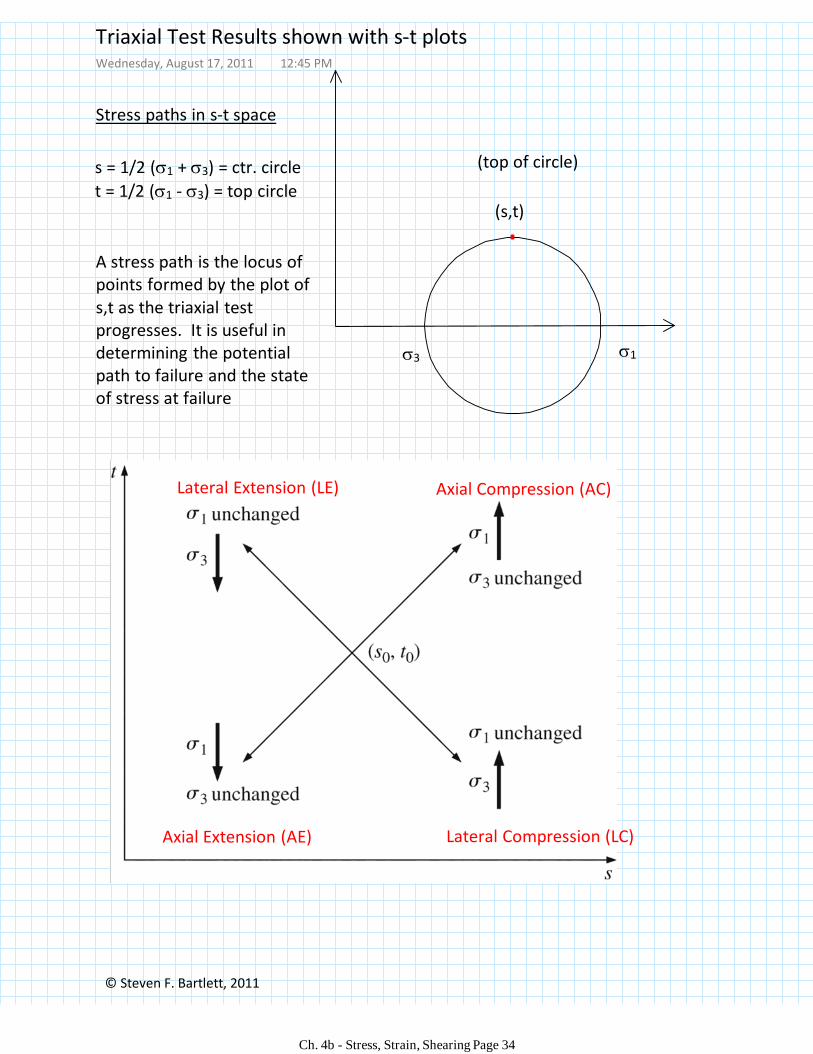
Stress paths in s-t space
s = 1/2 (1 + 3) = ctr. circle
t = 1/2 (1 - 3) = top circle(s,t)
(top of circle)
Axial Compression (AC)Lateral Extension (LE)
Lateral Compression (LC)Axial Extension (AE)
13
A stress path is the locus of points formed by the plot of s,t as the triaxial test progresses. It is useful in determining the potential path to failure and the state of stress at failure
Triaxial Test Results shown with s-t plotsWednesday, August 17, 2011 12:45 PM
Ch. 4b - Stress, Strain, Shearing Page 34
© Steven F. Bartlett, 2011
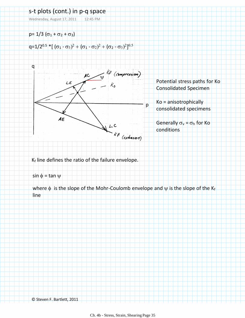
Potential stress paths for Ko Consolidated Specimen
Ko = anisotrophically consolidated specimens
Generally v = h for Ko conditions
p= 1/3 (1 + 2 + 3)
q=1/20.5 *[ (1 - (1 - (2 -
p
q
Kf line defines the ratio of the failure envelope.
sin = tan
where is the slope of the Mohr-Coulomb envelope and is the slope of the Kf
line
s-t plots (cont.) in p-q spaceWednesday, August 17, 2011 12:45 PM
Ch. 4b - Stress, Strain, Shearing Page 35
BlankWednesday, August 17, 2011 12:45 PM
Ch. 4b - Stress, Strain, Shearing Page 36
© Steven F. Bartlett, 2011
Ch. 4b - Stress, Strain, Shearing Page 37