centrifugal step systems owner's manual - · pdf file · 2015-02-28centrifugal...
TRANSCRIPT
SECTION: C1.50.130CL0032
0212Supersedes
0911
®® 3649 Cane Run Road . Louisville, KY 40211-1961
877-244-9340 . Fax: 877-414-4316www.clarusenvironmental.com
Centrifugal STEP SystemsOWNER'S MANUAL
© Copyright 2012. All rights reserved.
Owner’s InformationModel Number: ______________________ Date Code: _________________
Job Name: ______________________________________________________
Dealer: _________________________________________________________
Date of Purchase: _______________________________________________
Contractor: _____________________________________________________
Date of Installation: _______________________________________________
System Readings During Operation: Voltage __________ Amps _________
Safety InstructionsTO AVOID SERIOuS OR fATAl PERSONAl INJuRy OR MAJOR PROPERTy DAMAgE, READ AND fOllOw All SAfETy INSTRuCTIONS IN MANuAl AND ON THE PuMP.
THIS MANuAl IS INTENDED TO ASSIST IN THE INSTAllATION AND OPERATION Of THIS uNIT AND SHOulD bE kEPT wITH THE SySTEM.
This is a SAfETy AlERT SyMbOl.When you see this symbol on the pump or in the manual, look for one of the following signal words and be alert to the potential for personal injury or property damage.
Warns of hazards that wIll cause serious personal injury, death or major property damage.Warns of hazards that CAN cause serious personal injury, death or major property damage.Warns of hazards that CAN cause personal injury or property damage.INDICATES SPECIAL INSTRUCTIONS WHICH ARE VERY IMPORTANT AND MUST BE FOLLOWED.
THOROugHly REVIEw All INSTRuCTIONS AND wARNINgS PRIOR TO PERfORMINg ANy wORk ON THIS PuMP.
MAINTAIN All SAfETy DECAlS.
Safety Instructions .......................................................................... 1Limited Warranty............................................................................. 2Preinstallation Information .............................................................. 2Pump Performance Data ................................................................ 3General Instructions ....................................................................... 3System Instructions .....................................................................4-5System Wiring Instructions ............................................................. 5Operation ........................................................................................ 6Replacement Parts ......................................................................... 7Maintenance & Trouble Shooting ................................................... 8
Table of Contents
REfER TO wARRANTy ON PAgE 2.
Please read and review this manual before installing the product. The instructions contained herein, when followed correctly, will not only ensure a long and problem-free life for the system, but also save time and money during installation. Should further assistance be necessary please call Clarus Environmental at 1-877-244-9340.
Congratulations on the purchase of the Clarus Environmental Centrifugal STEP System. This system will provide years of trouble-free service when installed according to the manufacturer's recommendations.
2© Copyright 2012. All rights reserved.
Limited Warranty
lifetime warranty: Every Clarus Environmental filter is guaranteed to be free from defects in materials and workmanship for the lifetime of the homeowner/purchaser. Free repair or replacement, excluding labor, will be made on return of the filter prepaid to the factory. This warranty is limited to product proven to be free from abuse or improper installation.
Manufacturer warrants, to the purchaser and subsequent owner during the warranty period, every new product to be free from defects in material and workmanship under normal use and service, when properly used and maintained, for a period of one year from date of purchase by the end user, or 18 months from date of original manufacture of the product, whichever comes first. Parts that fail within the warranty period, one year from date of purchase by the end user, or 18 months from the date of original manufacture of the product, whichever comes first, that inspections determine to be defective in material or workmanship, will be repaired, replaced or remanufactured at manufacturer's option, provided however, that by so doing we will not be obligated to replace an entire assembly, the entire mechanism or the complete unit. No allowance will be made for shipping charges, damages, labor or other charges that may occur due to product failure, repair or replacement.
This warranty does not apply to and there shall be no warranty for any material or product that has been disassembled without prior approval of manufacturer, subjected to misuse, misapplication, neglect, alteration, accident or act of God; that has not been installed, operated or maintained in accordance with manufacturer's installation instructions; that has been exposed to outside substances including but not limited to the following: sand, gravel, cement, mud, tar, hydrocarbons, hydrocarbon derivatives (oil, gasoline, solvents, etc.), or other abrasive or corrosive substances, wash towels or feminine sanitary products, etc. in all pumping applications. The warranty set
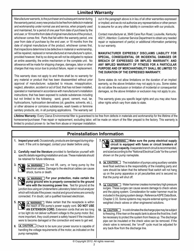
Preinstallation Information 7. Make sure the pump electrical supply
circuit is equipped with fuses or circuit breakers of proper capacity. A separate branch circuit is recommended,
and sized according to the “National Electrical Code” for the current shown on the pump nameplate.
8. The installation of pumps using auxiliary variable level float switches is the responsibility of the installing party and care should be taken that the tethered float switch will not hang up on the pump apparatus or pit peculiarities and is secured so that the pump will shut off.
9. Water hammer creates momentary high pressure surges. These surges can cause severe damage to check valves and the piping system. Consideration for water hammer must be included in the piping system design. Reference ASPE Data Book, Chapter 2.33. Some systems may require external spring or lever weighted check valves or other engineered solutions.
10. In cold climates the discharge pipe may be subject to freezing. If the riser on the septic tank is above the frost line, it will be necessary to protect the system from freeze up. The discharge pipe can be insulated or the check valve can be removed. If the check valve is removed, the “on-off” cycle must be adjusted for any back-flow from the discharge line.
1. Inspect your unit. Occasionally, products are damaged during ship-ment. If the unit is damaged, contact your dealer before using.
2. Carefully read the literature provided to familiarize yourself with specific details regarding installation and use. These materials should be retained for future reference.
3. Do not lift, carry, or hang pump by the electrical cables. Damage to the electrical cables can cause shock, burns or death.
4. for your protection, make certain the pump ground wire is properly connected to the ground wire with the incoming power line. Test for ground at the
junction box using an Underwriters Laboratory listed circuit analyzer which will indicate if the power, neutral and ground wires are correctly connected. If in doubt, call a qualified licensed electrician.
5. Make certain that the receptacle is within
the reach of the pump’s power supply cord. DO NOT uSE AN EXTENSION CORD. Extension cords that are too long
or too light do not deliver sufficient voltage to the pump motor. But, more important, they could present a safety hazard if the insulation were to become damaged or the connection end were to get wet.
6. Check to be sure your power source is capable of handling the voltage requirements of the motor, as indicated on the pump nameplate.
out in the paragraph above is in lieu of all other warranties expressed or implied; and we do not authorize any representative or other person to assume for us any other liability in connection with our products.
Contact manufacturer at, 3649 Cane Run Road, Louisville, Kentucky 40211, Attention: Customer Service Department to obtain any needed repair or replacement of part(s) or additional information pertaining to our warranty.
MANufACTuRER EXPRESSly DISClAIMS lIAbIlITy fOR SPECIAl, CONSEQuENTIAl OR INCIDENTAl DAMAgES OR bREACH Of EXPRESSED OR IMPlIED wARRANTy; AND ANy IMPlIED wARRANTy Of fITNESS fOR A PARTICulAR PuRPOSE AND Of MERCHANTAbIlITy SHAll bE lIMITED TO THE DuRATION Of THE EXPRESSED wARRANTy.
Some states do not allow limitations on the duration of an implied warranty, so the above limitation may not apply to you. Some states do not allow the exclusion or limitation of incidental or consequential damages, so the above limitation or exclusion may not apply to you.
This warranty gives you specific legal rights and you may also have other rights which vary from state to state.
3© Copyright 2012. All rights reserved.
General Instructions1. Clarus Environmental Centrifugal STEP Systems are designed for
installation in septic tanks through the riser on the discharge end of the tank. See Fig. 1. If a complete system has been purchased, all the components will be included except external pipe, fittings, and riser. Check your Local Code for alarm requirements.
2. All installations must comply with all applicable electrical and plumbing codes, including, but not limited to, National Electrical Code, local, regional, and/or state plumbing codes, etc.
3. If the Clarus Environmental Centrifugal STEP System is being retrofitted into an existing septic system, it will be necessary to pump and clean out the septic tank before installing. Before pumping, measure down to the liquid level in the septic tank (not the scum layer) from the septic tank lid and record. The septic tank lid becomes the reference point for measuring to correctly
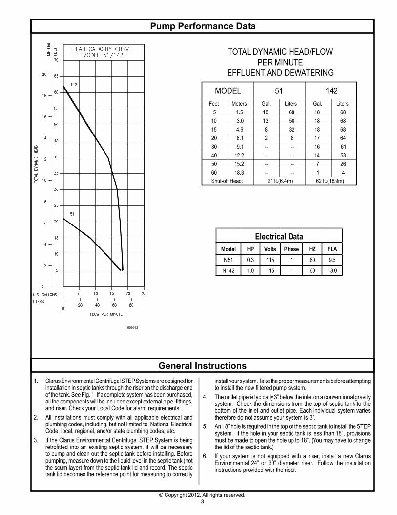
Pump Performance Data
Electrical DataModel HP Volts Phase HZ flAN51 0.3 115 1 60 9.5N142 1.0 115 1 60 13.0
009962
install your system. Take the proper measurements before attempting to install the new filtered pump system.
4. The outlet pipe is typically 3” below the inlet on a conventional gravity system. Check the dimensions from the top of septic tank to the bottom of the inlet and outlet pipe. Each individual system varies therefore do not assume your system is 3”.
5. An 18” hole is required in the top of the septic tank to install the STEP system. If the hole in your septic tank is less than 18”, provisions must be made to open the hole up to 18”. (You may have to change the lid of the septic tank.)
6. If your system is not equipped with a riser, install a new Clarus Environmental 24” or 30” diameter riser. Follow the installation instructions provided with the riser.
TOTAL DYNAMIC HEAD/FLOWPER MINUTE
EFFLUENT AND DEWATERING
MODELMeters
Shut-off Head:
51 142Feet Gal. Liters Gal. Liters
21 ft.(6.4m) 62 ft.(18.9m)
5 1.5 18 68 18 6810 3.0 13 50 18 6815 4.6 8 32 18 6820 6.1 2 8 17 6430 9.1 -- -- 16 6140 12.2 -- -- 14 5350 15.2 -- -- 7 2660 18.3 -- -- 1 4
4© Copyright 2012. All rights reserved.
15 3/8"
24 3/8"
42 5/8"
3 1/2" OF TETHERLENGTH FROM STRAP
8 3/4" REF.
ALARM FLOAT/PUMP FLOAT(TETHERED ON OPPOSITESIDE OF OTHER)
ALARM FLOAT
PUMP FLOAT
PUMP "ON"
PUMP "OFF" 4"8"
ALARM "ON"
10"
45 7/8"
LIQUID LEVEL
CODE
18" TYP.CONSULT LOCAL
EFFLUENTCLEAR
RELATIVELY
INLET2" 3" MIN.
TO ALARM
TO POWER SOURCE
2" PVC CONDUIT SUPPLIED BY OTHERS
QWIK BOX
FILTERED EFFLUENT
PUMP "ON"
PUMP "OFF" 4"
8"
ALARM "ON"
10"
ABOVE GRADE APPLICATION
BELOW GRADE APPLICATION
sk1684
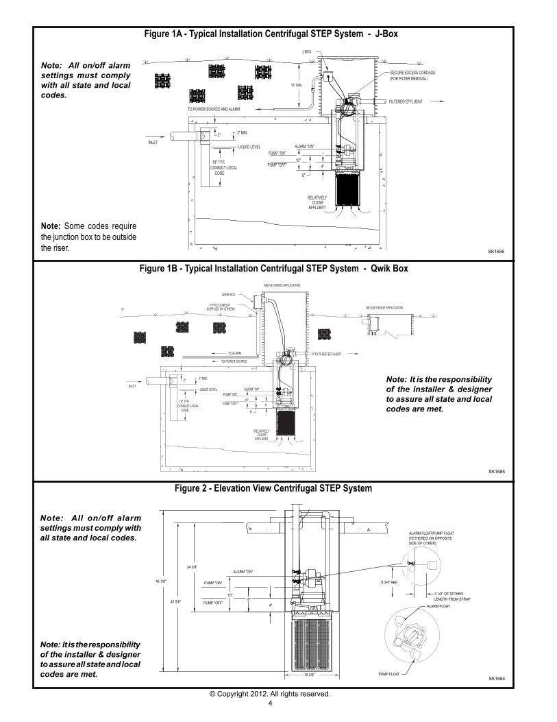
figure 2 - Elevation View Centrifugal STEP System
Note: All on/off alarm settings must comply with all state and local codes.
Note: It is the responsibility of the installer & designer to assure all state and local codes are met.
sk1685
figure 1b - Typical Installation Centrifugal STEP System - Qwik box
Note: It is the responsibility of the installer & designer to assure all state and local codes are met.
PUMP "ON"
PUMP "OFF"18" TYP.
CODECONSULT LOCAL
INLET2"
LIQUID LEVEL
3" MIN.
4"
RELATIVELY
EFFLUENTCLEAR
8"
FILTERED EFFLUENT
ALARM "ON"
10"
J-BOX
18" MIN.
TO POWER SOURCE AND ALARM
SECURE EXCESS CORDAGE(FOR FILTER REMOVAL)
sk1686
Note: Some codes require the junction box to be outside the riser.
Note: All on/off alarm settings must comply with all state and local codes.
figure 1A - Typical Installation Centrifugal STEP System - J-box
5© Copyright 2012. All rights reserved.
7. Bring piping from the lateral field to the outside of the riser on the septic tank. Note: If installing a system using a control panel follow the instructions included with the panel and skip steps 11-12 and 15.
8. Disconnect Clarus Environmental flexible pipe assembly at union on ball valve. Install pipe seal through the riser wall (2” hole saw required) to prevent ground water intrusion. Install flexible pipe through pipe seal with union ball valve on inside of riser as shown in Figure 1A. Solvent weld flexible pipe to lateral field piping using PVC pipe cement.
9. Connect other part of 1 ¼” discharge pipe assembly to pump outlet with pump setup outside the pump tank.
10. Tie off power cord by strapping to the discharge pipe. Make certain the cord cannot become entangled or obstruct the movement of the floats.
11. Install wire from power source and the alarm. See Fig. 1A or 1B. If a junction box is being used, Fig. 1A, install inside the septic tank riser. If a Qwik Box System is being used, Fig. 1B, install outside of septic tank riser as shown in Fig. 1B or inside of septic tank riser. Note: Some codes require the junction box to be outside the riser.
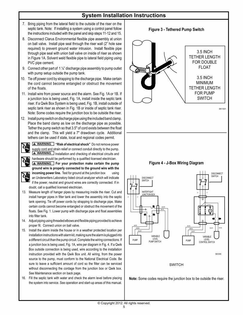
12. Install pump switch on discharge pipe using the included band clamp. Place the band clamp as low on the discharge pipe as possible. Tether the pump switch so that 3.5" of cord exists between the float and the clamp. This will yield a 7" drawdown cycle. Additional tethers can be used if state, local and regional codes permit.
System Installation Instructions
figure 3 - Tethered Pump Switch
sk1301
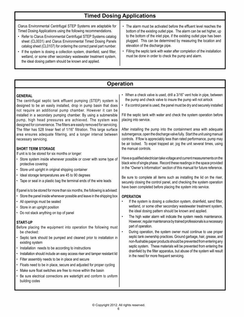
Note: Some codes require the junction box to be outside the riser.
figure 4 - J-box wiring Diagram
“Risk of electrical shock” Do not remove power supply cord and strain relief or connect conduit directly to the pump.
Installation and checking of electrical circuits and hardware should be performed by a qualified licensed electrician.
for your protection make certain the pump ground wire is properly connected to the ground wire with the incoming power line. Test for ground at the junction box using an Underwriters Laboratory listed circuit analyzer which will indicate if the power, neutral and ground wires are correctly connected. If in
doubt, call a qualified licensed electrician. 13. Measure length of hanger pipes by measuring inside the riser. Cut and
install hanger pipes in filter tank and lower the assembly into the septic tank opening. Tie off power cords by strapping to discharge pipe. Make certain cords cannot become entangled or obstruct the movement of the floats. See Fig. 1. Lower pump with discharge pipe and float assemblies into filter tank.
14. Adjust piping using threaded elbows and flexible piping provided to achieve proper fit. Connect union on ball valve.
15. Install the alarm inside the house or in a weather protected location per installation instructions with alarm kit, making sure the alarm is plugged into a different circuit than the pump circuit. Complete the wiring connections. If a junction box is being used, Fig. 1A, wire per diagram in Fig. 4. If a Qwik Box outside connection is being used, wire according to the installation instruction provided with the Qwik Box unit. All wiring, from the power source to the pump, must conform to the National Electrical Code. Be sure to leave a sufficient amount of cord so the filter can be serviced without disconnecting the cordage from the junction box or Qwik box. See Maintenance section on back page.
16. Fill the septic tank with water and check the alarm level before placing the system into service. See operation and start-up areas of this manual.
sWITCH
sk306
3.5 INCHTETHER LENGTH
FOR DOUBLEFLOAT
3.5 INCHMINIMUM
TETHER LENGTHFOR PUMP
SWITCH
WHITE
BLACK
WHITE
GREEN
BLACK BLACK
GREEN
WHITEBLACK WHITE
R
L1L2
L2 L1
PUMP
DISCONNECTSWITCH
WATERTIGHTJUNCTION BOX
VARIABLELEVEL
PUMP SWITCH PUMP CONTROL SWITCH
VARIABLELEVEL
DISCONNECTSWITCH
6© Copyright 2012. All rights reserved.
Operation
gENERAlThe centrifugal septic tank effluent pumping (STEP) system is designed to be an easily installed, drop in pump basin that does not require an additional pump chamber. However it can be installed in a secondary pumping chamber. By using a submersible pump, high head pressures are achieved. The system was designed for convenience. The filters are easily removed for servicing. The filter has 528 linear feet of 1/16” filtration. This large surface area ensures adequate filtering, and a longer interval between necessary servicing.
SHORT TERM STORAgEIf unit is to be stored for six months or longer:• Store system inside whenever possible or cover with some type of
protective covering• Store unit upright in original shipping container• Ideal storage temperatures are 45 to 90 degrees• Tape or seal in a plastic bag the terminal ends of the wire leads
If panel is to be stored for more than six months, the following is advised:• Store the panel inside whenever possible and leave in the shipping box• All openings must be sealed• Store in an upright position• Do not stack anything on top of panel
START-uPBefore placing the equipment into operation the following must
be checked:• Septic tank should be pumped and cleaned prior to installation in
existing system• Installation needs to be according to instructions• Installation should include an easy access riser and tamper resistant lid• Filter assembly needs to be in place and secure• Floats need to be in place, secure and adjusted for proper cycling• Make sure float switches are free to move within the basin• Be sure electrical connections are watertight and conform to uniform
building codes
• When a check valve is used, drill a 3/16” vent hole in pipe, between the pump and check valve to insure the pump will not airlock
• If a control panel is used, the panel must be dry and securely installed
Fill the septic tank with water and check the system operation before placing into service.
After installing the pump into the containment area with adequate submergence, open the discharge valve fully. Start the unit using manual controls. If flow is appreciably less than rated performance, pump may be air locked. To expel trapped air, jog the unit several times, using the manual controls.
Have a qualified electrician take voltage and current measurements on the black wire of single phase. Record these readings in the space provided in the “Owner’s Information” section of this manual for future reference.
Be sure to complete all items such as installing the lid on the riser, securely closing the control panel, and checking the system operation have been completed before placing the system into service.
OPERATION• If the system is dosing a collection system, drainfield, sand filter,
wetland, or some other secondary wastewater treatment system, the ideal dosing pattern should be known and applied.
• The high water alarm will indicate the system needs maintenance. However, regular maintenance by trained professionals is a necessary part of operation.
• During operation, the system owner must continue to use proper septic tank ownership practices. Ground garbage, hair, grease, and non-flushable paper products should be prevented from entering any septic system. These materials will be prevented from entering the drainfield by the filter apparatus, but abuse of the system will result in the need for more frequent servicing.
Timed Dosing Applications
Clarus Environmental Centrifugal STEP Systems are adaptable for Timed Dosing Applications using the following recommendations.• Refer to Clarus Environmental Centrifugal STEP Systems catalog
sheet (CL0031) and Clarus Environmental Timed Dosing Panels catalog sheet (CL0107) for ordering the correct panel part number.
• If the system is dosing a collection system, drainfield, sand filter, wetland, or some other secondary wastewater treatment system, the ideal dosing pattern should be known and applied.
• The alarm must be activated before the effluent level reaches the bottom of the existing outlet pipe. The alarm can be set higher, up to the bottom of the inlet pipe, if the existing outlet pipe has been plugged. This can be determined by measuring the location and elevation of the discharge pipe.
• Filling the septic tank with water after completion of the installation must be done in order to check the pump and alarm.
7© Copyright 2012. All rights reserved.
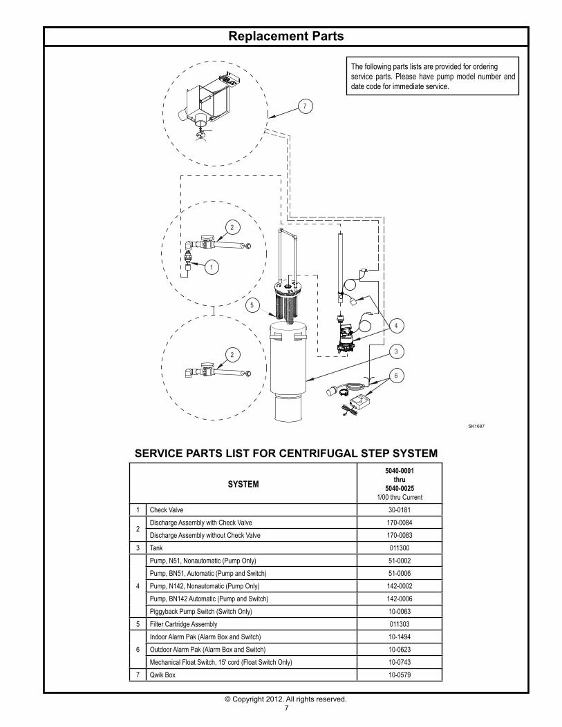
Replacement Parts
The following parts lists are provided for orderingservice parts. Please have pump model number and date code for immediate service.
SySTEM5040-0001
thru5040-0025
1/00 thru Current1 Check Valve 30-0181
2Discharge Assembly with Check Valve 170-0084Discharge Assembly without Check Valve 170-0083
3 Tank 011300
4
Pump, N51, Nonautomatic (Pump Only) 51-0002Pump, BN51, Automatic (Pump and Switch) 51-0006Pump, N142, Nonautomatic (Pump Only) 142-0002Pump, BN142 Automatic (Pump and Switch) 142-0006Piggyback Pump Switch (Switch Only) 10-0063
5 Filter Cartridge Assembly 011303
6Indoor Alarm Pak (Alarm Box and Switch) 10-1494Outdoor Alarm Pak (Alarm Box and Switch) 10-0623Mechanical Float Switch, 15' cord (Float Switch Only) 10-0743
7 Qwik Box 10-0579
7
6
4
3
5
2
1
2
sk1687
SERVICE PARTS LIST FOR CENTRIFUGAL STEP SYSTEM
© Copyright 2012. All rights reserved.
If the above checklist does not uncover the problem, consult the factory - Do not attempt to service or otherwise disassemble pump.
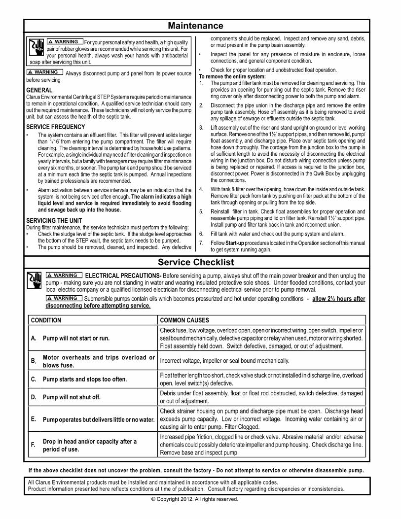
ElECTRICAl PRECAuTIONS- Before servicing a pump, always shut off the main power breaker and then unplug the pump - making sure you are not standing in water and wearing insulated protective sole shoes. Under flooded conditions, contact your local electric company or a qualified licensed electrician for disconnecting electrical service prior to pump removal.
Submersible pumps contain oils which becomes pressurized and hot under operating conditions - allow 2½ hours after disconnecting before attempting service.
Maintenance For your personal safety and health, a high quality
pair of rubber gloves are recommended while servicing this unit. For your personal health, always wash your hands with antibacterial
soap after servicing this unit.
Always disconnect pump and panel from its power source before servicing
gENERAlClarus Environmental Centrifugal STEP Systems require periodic maintenance to remain in operational condition. A qualified service technician should carry out the required maintenance. These technicians will not only service the pump unit, but can assess the health of the septic tank.
SERVICE fREQuENCy• The system contains an effluent filter. This filter will prevent solids larger
than 1/16” from entering the pump compartment. The filter will require cleaning. The cleaning interval is determined by household use patterns. For example, a single individual may need a filter cleaning and inspection on yearly intervals, but a family with teenagers may require filter maintenance every six months, or sooner. The pump tank and pump should be serviced at a minimum each time the septic tank is pumped. Annual inspections by trained professionals are recommended.
• Alarm activation between service intervals may be an indication that the system is not being serviced often enough. The alarm indicates a high liquid level and service is required immediately to avoid flooding and sewage back up into the house.
SERVICINg THE uNITDuring filter maintenance, the service technician must perform the following:• Check the sludge level of the septic tank. If the sludge level approaches
the bottom of the STEP vault, the septic tank needs to be pumped.• The pump should be removed, cleaned, and inspected. Any defective
components should be replaced. Inspect and remove any sand, debris, or mud present in the pump basin assembly.
• Inspect the panel for any presence of moisture in enclosure, loose connections, and general component condition.
• Check for proper location and unobstructed float operation.To remove the entire system: 1. The pump and filter tank must be removed for cleaning and servicing. This
provides an opening for pumping out the septic tank. Remove the riser ring cover only after disconnecting power to both the pump and alarm.
2. Disconnect the pipe union in the discharge pipe and remove the entire pump tank assembly. Hose off assembly as it is being removed to avoid any spillage of sewage or effluents outside the septic tank.
3. Lift assembly out of the riser and stand upright on ground or level working surface. Remove one of the 1½” support pipes, and then remove lid, pump/float assembly, and discharge pipe. Place over septic tank opening and hose down thoroughly. The cordage from the junction box to the pump is of sufficient length to avoid the necessity of disconnecting the electrical wiring in the junction box. Do not disturb wiring connection unless pump is being replaced or repaired. If access is required to the junction box, disconnect power. Power is disconnected in the Qwik Box by unplugging the connections.
4. With tank & filter over the opening, hose down the inside and outside tank. Remove filter pack from tank by pushing on filter pack at the bottom of the tank through opening or pulling from the top side.
5. Reinstall filter in tank. Check float assemblies for proper operation and reassemble pump piping and lid on filter tank. Reinstall 1½” support pipe. Install pump and filter tank back in tank and reconnect union.
6. Fill tank with water and check out the pump system and alarm. 7. Follow Start-up procedures located in the Operation section of this manual
to get system running again.
Service Checklist
CONDITION COMMON CAuSES
A. Pump will not start or run.Check fuse, low voltage, overload open, open or incorrect wiring, open switch, impeller or seal bound mechanically, defective capacitor or relay when used, motor or wiring shorted. Float assembly held down. Switch defective, damaged, or out of adjustment.
b. Motor overheats and trips overload or blows fuse. Incorrect voltage, impeller or seal bound mechanically.
C. Pump starts and stops too often. Float tether length too short, check valve stuck or not installed in discharge line, overload open, level switch(s) defective.
D. Pump will not shut off. Debris under float assembly, float or float rod obstructed, switch defective, damaged or out of adjustment.
E. Pump operates but delivers little or no water.Check strainer housing on pump and discharge pipe must be open. Discharge head exceeds pump capacity. Low or incorrect voltage. Incoming water containing air or causing air to enter pump. Filter Clogged.
f. Drop in head and/or capacity after a period of use.
Increased pipe friction, clogged line or check valve. Abrasive material and/or adverse chemicals could possibly deteriorate impeller and pump housing. Check discharge line. Remove base and inspect pump.
All Clarus Environmental products must be installed and maintained in accordance with all applicable codes.Product information presented here reflects conditions at time of publication. Consult factory regarding discrepancies or inconsistencies.