cements and materials for well cementing -...
TRANSCRIPT
This document is not an API Standard; it is under consideration within an API technical committee but has not received all
approvals required to become an API Standard. It shall not be reproduced or circulated or quoted, in whole or in part,
outside of API committee activities except with the approval of the Chairman of the committee having jurisdiction and staff
of the API Standards Dept. Copyright API. All rights reserved.
Cements and Materials for Well Cementing
API SPECIFICATION 10A TWENTY-FIFTH EDITION, [MONTH][YEAR]
API MONOGRAM PROGRAM EFFECTIVE DATE: [MONTH][DAY][YEAR]
This document is not an API Standard; it is under consideration within an API technical committee but has not received all
approvals required to become an API Standard. It shall not be reproduced or circulated or quoted, in whole or in part,
outside of API committee activities except with the approval of the Chairman of the committee having jurisdiction and staff
of the API Standards Dept. Copyright API. All rights reserved.
Introduction
It is necessary that users of this specification be aware that further or differing requirements can be required for individual applications. This specification is not intended to inhibit a vendor from offering, or the purchaser from accepting, alternative equipment or engineering solutions for the individual application. This can be particularly applicable where there is innovative or developing technology. Where an alternative is offered, it is the responsibility of the vendor to identify any variations from this specification and provide details.
In this specification, where practical, US Customary (USC) units are included in brackets for information. The units do not necessarily represent a direct conversion of SI to USC units, or USC to SI units. Consideration has been given to the precision of the instrument making the measurement. For example, thermometers are typically marked in 1° increments, thus temperature values have been rounded to the nearest degree.
In this specification, calibrating an instrument refers to assuring the accuracy of the measurement. Accuracy is the degree of conformity of a measurement of a quantity to its actual or true value. Accuracy is related to precision, or reproducibility, of a measurement. Precision is the degree to which further measurements or calculations will show the same or similar results. Precision is characterized in terms of the standard deviation of the measurement. The results of calculations or a measurement can be accurate, but not precise, precise but not accurate, neither or both. A result is valid if it is both accurate and precise.
Page 3 of 69
Cements and Materials for Well Cementing
1 Scope
1.1 General
This specification specifies requirements and gives recommendations for six classes of well cements, including their chemical and physical requirements, and procedures for physical testing. Annex B informs about two more classes of composite cements.
This specification is applicable to well cement classes A, B, C, and D, which are the products obtained by grinding Portland cement clinker and, if needed, calcium sulfate as an interground additive. Processing additives can be used in the manufacture of cement of these classes. Suitable set-modifying agents can be interground or blended during manufacture of Class D cement. Annex B describes composite well cement classes which are the products obtained by intergrinding Portland cement clinker and one or more forms of calcium sulfate with composite constituents, or by subsequent blending of separately produced Portland cement with separately processed composite constituents. Composite constituents are also specified in Annex B.
This specification is also applicable to well cement classes G and H, which are the products obtained by grinding clinker with no additives other than one or more forms of calcium sulfate, water, or chemical additives as required for chromium(VI) reduction.
1.2 Application of the API Monogram
When product is manufactured at a facility licensed by API and it is intended to be supplied bearing the API Monogram, the requirements of Annex A apply.
1.3 Use of Metric SI and US Customary Units
This document contains SI and US customary oilfield units. For the purposes of this document, the conversion between the systems is not exact and has been intentionally rounded to allow for ease of use in calibration and measurement.
2 Normative References
The following referenced documents are indispensable for the application of this document. For dated references, only the edition cited applies. For undated references, the latest edition of the referenced document applies (including any addenda/errata). For date references, only the edition cited applies. However, not all documents listed may apply to your specific needs. The body of the standard should be referred to for how these documents are specifically applied.
API Spec 13A, Specification for Drilling Fluid Materials
ASTM1 C109/C109M, Standard Test Method for Compressive Strength of Hydraulic Cement Mortars (Using 2-in. or [50-mm] Cube Specimens)
ASTM C114, Standard Test Methods for Chemical Analysis of Hydraulic Cement
ASTM C115, Standard Test Method for Fineness of Portland Cement by the Turbidimeter
ASTM C183, Standard Practice for Sampling and the Amount of Testing of Hydraulic Cement
ASTM C204, Standard Test Methods for Fineness of Hydraulic Cement by Air-Permeability Apparatus
ASTM C465, Standard Specification for Processing Additions for Use in the Manufacture of Hydraulic Cements
1 American Society for Testing and Materials, 100 Barr Harbor Drive, West Conshohoken, PA 19428-2959, USA;
www.astm.org

This document is not an API Standard; it is under consideration within an API technical committee but has not received all
approvals required to become an API Standard. It shall not be reproduced or circulated or quoted, in whole or in part,
outside of API committee activities except with the approval of the Chairman of the committee having jurisdiction and staff
of the API Standards Dept. Copyright API. All rights reserved.
ASTM E11, Standard Specification for Wire Cloth and Sieves for Testing Purposes
ASTM E1404-94, Standard Specification for Laboratory Glass Conical Flasks
EN2 196-1, Methods of testing cement — Part 1: Determination of strength
EN 196-2, Methods of testing cement — Part 2: Chemical analysis of cement
EN 196-6, Methods of testing cement — Part 6: Determination of fineness
EN 196-7, Methods of testing cement — Part 7: Methods of taking and preparing samples of cement
ISO3 3310-1, Test sieves — Technical requirements and testing — Part 1: Test sieves of metal wire cloth
ISO 24450, Laboratory glassware — Wide-necked boiling flasks
3 Terms, Definitions, Acronyms, and Abbreviations
3.1 Terms and Definitions
For the purposes of this document, the following terms and definitions apply.
3.1.1 additive Material added to a cement slurry to modify or enhance some desired property.
NOTE Properties that are commonly modified include setting time (by use of retarders or accelerators), fluid loss, viscosity, etc.
3.1.2 atmospheric pressure consistometer Device used for stirring and conditioning the cement slurry.
NOTE The device is not intended to measure thickening-time.
3.1.3 Bearden unit of consistency
Bc
Measure of the consistency of a cement slurry when determined on a pressurized consistometer.
3.1.4 blending A process in which two or more ingredients are combined into an intimate and uniform product of finely divided dry material, as by special blending equipment.
3.1.5 cement Portland cement Ground clinker generally consisting of hydraulic calcium silicates and aluminates and usually containing one or more forms of calcium sulfate as an interground additive.
3.1.6 cement class Designation for classification of well cement according to its intended use.
3.1.7 cement grade Designation achieved under the API system for denoting the sulfate resistance of a particular cement.
2 European Committee for Standardization, rue de Stassard 36, Brussels B-1050, Belgium; www.cen.eu
3 International Organization for Standardization, 1, ch. de la Voie-Creuse, Case postale 56, CH-1211 Geneva 20,
Switzerland; www.iso.org
This document is not an API Standard; it is under consideration within an API technical committee but has not received all
approvals required to become an API Standard. It shall not be reproduced or circulated or quoted, in whole or in part,
outside of API committee activities except with the approval of the Chairman of the committee having jurisdiction and staff
of the API Standards Dept. Copyright API. All rights reserved.
3.1.8 cement blend Mixture of dry cement and other dry materials.
3.1.9 clinker Fused materials produced in the kiln during cement manufacturing that are interground with calcium sulfate to make cement.
3.1.10 compressive strength Strength of a set cement sample measured by the force required to cause it to fail in compression, expressed as a force per unit of area.
3.1.11 consistometer Device used to measure the thickening-time of a cement slurry under temperature and under pressure.
NOTE An atmospheric consistometer is used to condition cement slurry for a free-fluid test.
3.1.12 filtrate Liquid that is forced out of a cement slurry during a fluid loss test.
3.1.13 free-fluid (free-water) Colored or colorless liquid that separates from a cement slurry under static conditions.
3.1.14 intergrinding A process involving grinding Portland cement clinker with suitable other components to produce finely divided dry material.
3.1.15 load frame Frame to place a load on cement samples for determining compressive strength of cement.
3.1.16 slurry container (slurry cup) Container in an atmospheric or pressurized consistometer used to hold the slurry for conditioning purposes or for the thickening-time test.
3.1.17 thickening-time Time after which the consistency of a cement slurry has become so high that the slurry is considered unpumpable.
NOTE The results of a thickening-time test provide an indication of the length of time a cement slurry remains pumpable under the test conditions.
3.1.18 white mineral oil A colorless, odorless, oily, almost tasteless water insoluble liquid consisting of a mixture of hydrocarbons obtained by distillation.
3.2 Acronyms and Abbreviations
For the purposes of this document, the following terms and definitions apply.
ASTM American Society for Testing and Materials
This document is not an API Standard; it is under consideration within an API technical committee but has not received all
approvals required to become an API Standard. It shall not be reproduced or circulated or quoted, in whole or in part,
outside of API committee activities except with the approval of the Chairman of the committee having jurisdiction and staff
of the API Standards Dept. Copyright API. All rights reserved.
C3A tricalcium aluminate
C4AF tetracalcium aluminoferrite
C3S tricalcium silicate
EN European Committee for Standardization
HSR high sulfate-resistant
INSP inspection (dimension requiring verification)
ISO International Standardization Organization
MSR moderate sulfate-resistant
NIST National Institute of Standards and Technology
O ordinary
4 Requirements
4.1 Specification, Chemical and Physical Requirements
4.1.1 Classes and Grades
4.1.1.1 General
Well cement shall be specified using the classes A, B, C, D, G, or H and the grades: ordinary (O), moderate sulfate-resistant (MSR), and high sulfate-resistant (HSR). Composite well cements shall be specified using the classes K and L consisting of Portland cements and additional composite constituents which are described in Annex B of this document.
A well cement that has been manufactured and supplied in accordance with this specification may be mixed and placed in the field using alternate water ratios and/or additives. It is not intended that manufacturing compliance with this specification be based on such field conditions.
Processing additives, set modifying agents, or chemical additives used to reduce chromium(VI) shall not prevent a well cement from performing its intended functions.
4.1.1.2 Class A
This product is obtained by grinding clinker, consisting of hydraulic calcium silicates, containing one or more forms of calcium sulfate (CaSO4) as an interground additive. Processing additives may be used in the manufacture of Class A cement, provided that such materials in the amounts used meet the requirements of ASTM C465.
NOTE This product is intended for use when special properties are not required and is available only in O grade, similar to ASTM C150, Type I.
4.1.1.3 Class B
This product is obtained by grinding clinker, consisting of hydraulic calcium silicates, containing one or more forms of calcium sulfate as an interground additive. Processing additives may be used in the manufacture of Class B cement, provided that such materials in the amounts used meet the requirements of ASTM C465.
NOTE This product is intended for use when conditions require moderate or high sulfate resistance and is available in both MSR and HSR grades, similar to ASTM C150, Type II.
4.1.1.4 Class C
This product is obtained by grinding clinker, consisting of hydraulic calcium silicates, containing one or more forms of calcium sulfate as an interground additive. Processing additives may be used in the manufacture of Class C cement, provided that such materials in the amounts used meet the requirements of ASTM C465.
This document is not an API Standard; it is under consideration within an API technical committee but has not received all
approvals required to become an API Standard. It shall not be reproduced or circulated or quoted, in whole or in part,
outside of API committee activities except with the approval of the Chairman of the committee having jurisdiction and staff
of the API Standards Dept. Copyright API. All rights reserved.
NOTE This product is intended for use when conditions require high, early strength, and is available in O, MSR, and HSR grades, similar to ASTM C150, Type III.
4.1.1.5 Class D
This product is obtained by grinding clinker, consisting of hydraulic calcium silicates, containing one or more forms of calcium sulfate as an interground additive. Processing additives may be used in the manufacture of Class D cement, provided that such materials in the amounts used meet the requirements of ASTM C465. Further, at the option of the manufacturer, suitable set-modifying agents may be interground or blended during manufacture.
NOTE This product is intended for use under conditions of moderately high temperatures and pressures and is available in MSR and HSR grades.
4.1.1.6 Class G
This product is obtained by grinding clinker, consisting of hydraulic calcium silicates, containing one or more forms of calcium sulfate as an interground additive. No additives other than calcium sulfate, water, or chemical additives as required for chromium (VI) reduction, shall be interground or blended with the clinker during manufacture of Class G well cement, provided that such additives do not prevent the well cement from performing its intended purpose.
NOTE This product is intended for use as a basic well cement and is available in MSR and HSR grades.
4.1.1.7 Class H
This product is obtained by grinding clinker, consisting of hydraulic calcium silicates, containing one or more forms of calcium sulfate as an interground additive. No additives other than calcium sulfate, water, or chemical additives as required for chromium (VI) reduction, shall be interground or blended with the clinker during manufacture of Class H well cement, provided that such additives do not prevent the well cement from performing its intended purpose.
NOTE This product is intended for use as a basic well cement and is available in MSR and HSR grades.
4.1.1.8 Composite Well Cements
See Annex B for information on composite well cements.
4.1.2 Chemical Requirements
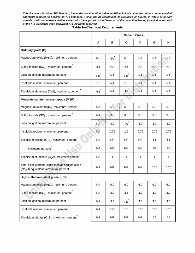
Well cements shall conform to the respective chemical requirements of classes and grades referenced in Table 1. This specification is only applicable to the testing of cements that conform to the chemical requirements of classes and grades as set forth in Table 1.
Chemical analyses of hydraulic cements shall be carried out as specified in ASTM C114
NOTE For the purposes of this provision, EN 196-2 is equivalent to ASTM C114.
This document is not an API Standard; it is under consideration within an API technical committee but has not received all
approvals required to become an API Standard. It shall not be reproduced or circulated or quoted, in whole or in part,
outside of API committee activities except with the approval of the Chairman of the committee having jurisdiction and staff
of the API Standards Dept. Copyright API. All rights reserved.
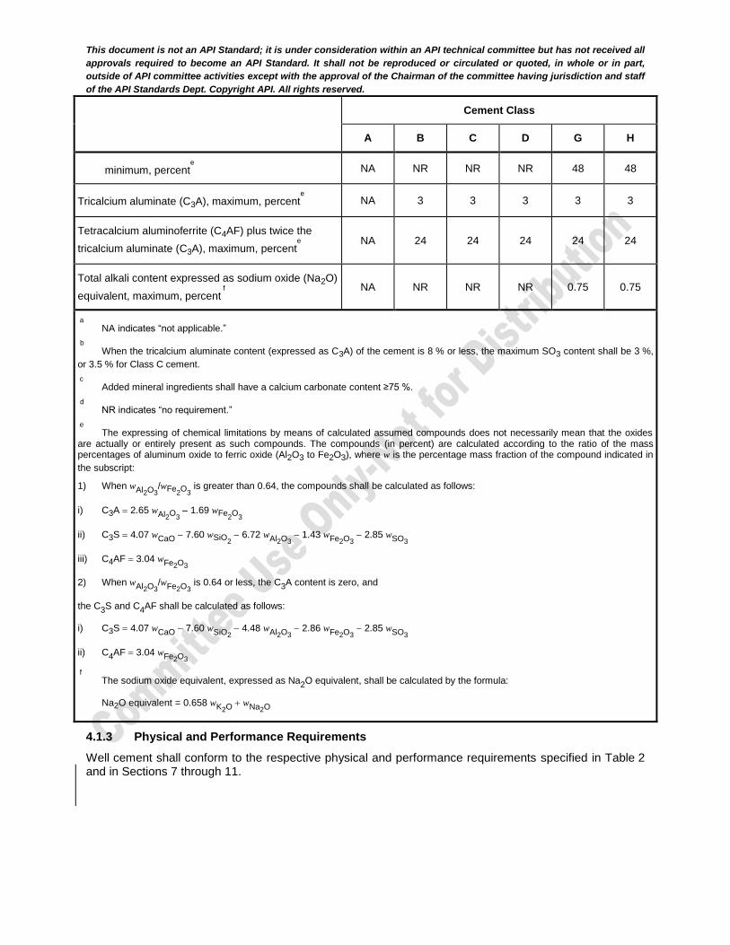
Table 1—Chemical Requirements
Cement Class
A B C D G H
Ordinary grade (O)
Magnesium oxide (MgO), maximum, percent 6.0 NAa
6.0 NA NA NA
Sulfur trioxide (SO3), maximum, percentb
3.5 NA 4.5 NA NA NA
Loss on ignition, maximum, percent 3.5c
NA 3.5c
NA NA NA
Insoluble residue, maximum, percent 1.5 NA 1.5 NA NA NA
Tricalcium aluminate (C3A), maximum, percente
NRd
NA 15 NA NA NA
Moderate sulfate-resistant grade (MSR)
Magnesium oxide (MgO), maximum, percent NA 6.0 6.0 6.0 6.0 6.0
Sulfur trioxide (SO3), maximum, percentb
NA 3.0 3.5 3.0 3.0 3.0
Loss on ignition, maximum, percent NA 3.0 3.5c
3.0 3.0 3.0
Insoluble residue, maximum, percent NA 0.75 1.5 0.75 0.75 0.75
Tricalcium silicate (C3S), maximum, percente
NA NR NR NR 58 58
minimum, percente
NA NR NR NR 48 48
Tricalcium aluminate (C3A), maximum percente
NA 8 8 8 8 8
Total alkali content, expressed as sodium oxide
(Na2O) equivalent, maximum, percentf
NA NR NR NR 0.75 0.75
High sulfate-resistant grade (HSR)
Magnesium oxide (MgO), maximum, percent NA 6.0 6.0 6.0 6.0 6.0
Sulfur trioxide (SO3), maximum, percentb
NA 3.0 3.5 3.0 3.0 3.0
Loss on ignition, maximum, percent NA 3.0 3.5c
3.0 3.0 3.0
Insoluble residue, maximum, percent NA 0.75 1.5 0.75 0.75 0.75
Tricalcium silicate (C3S), maximum, percente
NA NR NR NR 65 65
This document is not an API Standard; it is under consideration within an API technical committee but has not received all
approvals required to become an API Standard. It shall not be reproduced or circulated or quoted, in whole or in part,
outside of API committee activities except with the approval of the Chairman of the committee having jurisdiction and staff
of the API Standards Dept. Copyright API. All rights reserved.
Cement Class
A B C D G H
minimum, percente
NA NR NR NR 48 48
Tricalcium aluminate (C3A), maximum, percente
NA 3 3 3 3 3
Tetracalcium aluminoferrite (C4AF) plus twice the
tricalcium aluminate (C3A), maximum, percente
NA 24 24 24 24 24
Total alkali content expressed as sodium oxide (Na2O)
equivalent, maximum, percent f
NA NR NR NR 0.75 0.75
a
NA indicates “not applicable.”
b
When the tricalcium aluminate content (expressed as C3A) of the cement is 8 % or less, the maximum SO3 content shall be 3 %,
or 3.5 % for Class C cement.
c
Added mineral ingredients shall have a calcium carbonate content ≥75 %.
d
NR indicates “no requirement.”
e
The expressing of chemical limitations by means of calculated assumed compounds does not necessarily mean that the oxides are actually or entirely present as such compounds. The compounds (in percent) are calculated according to the ratio of the mass percentages of aluminum oxide to ferric oxide (Al2O3 to Fe2O3), where w is the percentage mass fraction of the compound indicated in
the subscript:
1) When wAl2O3/wFe
2O
3 is greater than 0.64, the compounds shall be calculated as follows:
i) C3A 2.65 wAl2O3 1.69 wFe
2O
3
ii) C3S 4.07 wCaO 7.60 wSiO2 6.72 wAl2O3
1.43 wFe2O3 2.85 wSO3
iii) C4AF 3.04 wFe2O3
2) When wAl2O3/wFe2O3
is 0.64 or less, the C3A content is zero, and
the C3S and C4AF shall be calculated as follows:
i) C3S 4.07 wCaO 7.60 wSiO2 4.48 wAl2O3
2.86 wFe2O3 2.85 wSO3
ii) C4AF 3.04 wFe2O3
f
The sodium oxide equivalent, expressed as Na2O equivalent, shall be calculated by the formula:
Na2O equivalent = 0.658 wK2O wNa2O
4.1.3 Physical and Performance Requirements
Well cement shall conform to the respective physical and performance requirements specified in Table 2 and in Sections 7 through 11.
This document is not an API Standard; it is under consideration within an API technical committee but has not received all
approvals required to become an API Standard. It shall not be reproduced or circulated or quoted, in whole or in part,
outside of API committee activities except with the approval of the Chairman of the committee having jurisdiction and staff
of the API Standards Dept. Copyright API. All rights reserved.
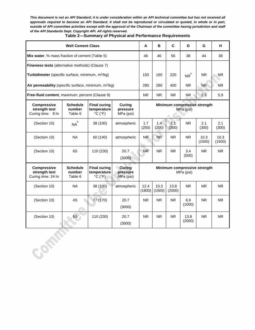
Table 2—Summary of Physical and Performance Requirements
Well Cement Class A B C D G H
Mix water, % mass fraction of cement (Table 5) 46 46 56 38 44 38
Fineness tests (alternative methods) (Clause 7)
Turbidimeter (specific surface, minimum, m2/kg) 150 160 220 NRa
NR NR
Air permeability (specific surface, minimum, m2/kg) 280 280 400 NR NR NR
Free-fluid content, maximum, percent (Clause 9) NR NR NR NR 5.9 5.9
Compressive strength test
Curing time: 8 hr
Schedule number
Table 6
Final curing temperature
°C (°F)
Curing pressure
MPa (psi)
Minimum compressive strength
MPa (psi)
(Section 10) NAb
38 (100) atmospheric 1.7 (250)
1.4 (200)
2.1 (300)
NR 2.1 (300)
2.1 (300)
(Section 10) NA 60 (140) atmospheric NR NR NR NR 10.3 (1500)
10.3 (1500)
(Section 10) 6S 110 (230) 20.7
(3000)
NR NR NR 3.4 (500)
NR NR
Compressive strength test
Curing time: 24 hr
Schedule number
Table 6
Final curing temperature
°C (°F)
Curing pressure
MPa (psi)
Minimum compressive strength
MPa (psi)
(Section 10) NA 38 (100) atmospheric 12.4 (1800)
10.3 (1500)
13.8 (2000)
NR NR NR
(Section 10) 4S 77 (170) 20.7
(3000)
NR NR NR 6.9 (1000)
NR NR
(Section 10) 6S 110 (230) 20.7
(3000)
NR NR NR 13.8 (2000)
NR NR

This document is not an API Standard; it is under consideration within an API technical committee but has not received all
approvals required to become an API Standard. It shall not be reproduced or circulated or quoted, in whole or in part,
outside of API committee activities except with the approval of the Chairman of the committee having jurisdiction and staff
of the API Standards Dept. Copyright API. All rights reserved.
Well Cement Class A B C D G H
Thickening-time test
Specification Test
schedule number
Tables 11 through 13
Maximum consistency
(15 min to 30 min stirring period)
Bc
c
Thickening-time
(minimum/maximum) minutes
(Section 11) 4 30 90/NR 90/NR 90/NR 90/NR NR NR
(Section 11) 5 30 NR NR NR NR 90/120 90/120
(Section 11) 6 30 NR NR NR 100/NR NR NR
a NR indicates “no requirement”.
b
NA indicates “not applicable”.
c
Bearden units of consistency, Bc, obtained on a pressurized consistometer as defined in Clause 10 and calibrated in accordance
with the same clause.
4.2 Sampling Frequency, Timing of Tests, and Equipment
4.2.1 Sampling Frequency
4.2.1.1 For well cement classes C, D, G, and H, a sample for testing shall be taken by either of the following frequencies. At the discretion of the manufacturer either method may be used:
a) over an interval of 24 hr; or
b) on a 1000 ton (maximum) production run.
4.2.1.2 For well cement classes A and B, a sample for testing shall be taken by either of the following frequencies. At the discretion of the manufacturer either method may be used:
a) over a 14 day continuous production interval; or
b) on a 25,000 ton (maximum) production run.
4.2.1.3 These samples shall represent the product as produced.
4.2.2 Time from Sampling to Testing
Each sample shall be tested for conformance to this specification. All tests shall be completed within seven working days after sampling.
4.2.3 Specified Equipment
Equipment used for testing well cements shall comply with Table 3. Dimensions shown in Figures 5 through 7 and Figures 10 through 13 are for the purposes of manufacturing the cement-specification test equipment. Dimensional recertification is not required.
This document is not an API Standard; it is under consideration within an API technical committee but has not received all
approvals required to become an API Standard. It shall not be reproduced or circulated or quoted, in whole or in part,
outside of API committee activities except with the approval of the Chairman of the committee having jurisdiction and staff
of the API Standards Dept. Copyright API. All rights reserved.
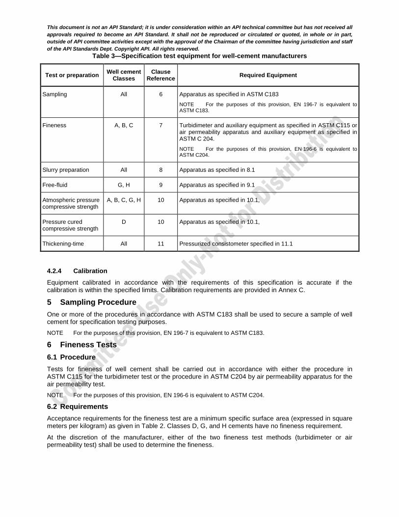
Table 3—Specification test equipment for well-cement manufacturers
Test or preparation Well cement
Classes Clause
Reference Required Equipment
Sampling All 6 Apparatus as specified in ASTM C183
NOTE For the purposes of this provision, EN 196-7 is equivalent to ASTM C183.
Fineness A, B, C 7 Turbidimeter and auxiliary equipment as specified in ASTM C115 or air permeability apparatus and auxiliary equipment as specified in ASTM C 204.
NOTE For the purposes of this provision, EN 196-6 is equivalent to ASTM C204.
Slurry preparation All 8 Apparatus as specified in 8.1
Free-fluid G, H 9 Apparatus as specified in 9.1
Atmospheric pressure compressive strength
A, B, C, G, H 10 Apparatus as specified in 10.1,
Pressure cured compressive strength
D 10 Apparatus as specified in 10.1,
Thickening-time All 11 Pressurized consistometer specified in 11.1
4.2.4 Calibration
Equipment calibrated in accordance with the requirements of this specification is accurate if the calibration is within the specified limits. Calibration requirements are provided in Annex C.
5 Sampling Procedure
One or more of the procedures in accordance with ASTM C183 shall be used to secure a sample of well cement for specification testing purposes.
NOTE For the purposes of this provision, EN 196-7 is equivalent to ASTM C183.
6 Fineness Tests
6.1 Procedure
Tests for fineness of well cement shall be carried out in accordance with either the procedure in ASTM C115 for the turbidimeter test or the procedure in ASTM C204 by air permeability apparatus for the air permeability test.
NOTE For the purposes of this provision, EN 196-6 is equivalent to ASTM C204.
6.2 Requirements
Acceptance requirements for the fineness test are a minimum specific surface area (expressed in square meters per kilogram) as given in Table 2. Classes D, G, and H cements have no fineness requirement.
At the discretion of the manufacturer, either of the two fineness test methods (turbidimeter or air permeability test) shall be used to determine the fineness.

This document is not an API Standard; it is under consideration within an API technical committee but has not received all
approvals required to become an API Standard. It shall not be reproduced or circulated or quoted, in whole or in part,
outside of API committee activities except with the approval of the Chairman of the committee having jurisdiction and staff
of the API Standards Dept. Copyright API. All rights reserved.
7 Preparation of Slurry for Free-fluid, Compressive Strength and Thickening-time Tests
7.1 Apparatus
7.1.1 All apparatuses are calibrated as per the requirements in Annex C
7.1.2 Electronic or Mechanical Balances
The indicated load on balances shall be accurate within 0.1 % of the actual load, unless measurements are being made between 0.1 g to 10 g for which the indicated load shall be within 0.01 g of the actual load. Balances shall have two decimal place precision reading.
7.1.3 Weight Sets
Weight sets include sets use daily for routine weighting and reference weight sets used for calibration. Weights should conform within ±0.1 % of the nominal mass except for weights with a mass equal or less than 10 g. For weights of 10 g and less should conform within ±0.02 g of the nominal mass. On beam-type scales where the reference weights are on the beam, the indicated masses shall conform to the requirements given in 8.1.2.
7.1.4 Sieves
A 850 µm wire cloth sieve (US sieve No. 20), in accordance with the requirements given in ASTM E11, shall be used for sieving cement prior to slurry preparation.
NOTE For the purposes of this provision, ISO 3310-1 is equivalent to ASTM E11 .
7.1.5 Mixing Devices
The mixing device for the preparation of well cement slurries shall be a 1 L (1 qt) size, bottom-drive, blade-type mixer, with a timing device able to measure both 15 s and 35 s. The mixing device shall be able to mix cement slurry at 4000 r/min rotational speed, and ±250 r/min at 12,000 r/min ±250 r/min rotational speed.
An example of a mixing device in common use is shown in Figure 1. The mixing-blade assembly and mixing container shall be constructed of durable, corrosion-resistant material. The mixing-blade assembly (see Figure 2) shall be constructed in such a manner that the blade can be removed for weighing and changing. The mixing blade shall be weighed initially and prior to each production run tested or every 30 days, whichever is greater. Replace with an unused blade if critical blade deformation has occurred or prior to a 10 % mass loss. The blade shall be mounted with its sharp edge on the leading edge rotation. If the mixing device leaks at any time during the mixing procedure, the contents shall be discarded, the leak shall be repaired and the procedure shall be restarted.

This document is not an API Standard; it is under consideration within an API technical committee but has not received all
approvals required to become an API Standard. It shall not be reproduced or circulated or quoted, in whole or in part,
outside of API committee activities except with the approval of the Chairman of the committee having jurisdiction and staff
of the API Standards Dept. Copyright API. All rights reserved.
Figure 1—Example of a Typical Cement-Mixing Device
Key
1 cap nut 5 socket head shaft
2 blade (installed with tapered edge down) 6 bearing holder
3 O-ring 7 hexagonal nut
4 thrust washer 8 bearing cap
Figure 2—Common Blade Assembly
7.2 Procedure
7.2.1 Sieving
Prior to mixing, the cement shall be sieved using the method described in ASTM C183 using a sieve defined in 8.1.3.
NOTE For the purposes of this provision, EN 196-7 is equivalent to ASTM C183 .
This document is not an API Standard; it is under consideration within an API technical committee but has not received all
approvals required to become an API Standard. It shall not be reproduced or circulated or quoted, in whole or in part,
outside of API committee activities except with the approval of the Chairman of the committee having jurisdiction and staff
of the API Standards Dept. Copyright API. All rights reserved.
7.2.2 Temperature of Water and Cement
The temperature of the mix water in the container within 60 s prior to mixing shall be 23 °C ±1 °C (73 °F ±2 °F) and the temperature of the cement within 60 s prior to mixing shall be 23 °C ±1 °C (73 °F ±2 °F).
7.2.3 Mix Water
Distilled or de-ionized water shall be used for testing. The mix water shall be weighed directly into a clean, dry mixing container. No water shall be added to compensate for evaporation, wetting, or other losses.
7.2.4 Mixing Quantities
The quantities of slurry component shown in Table 5 shall be used for testing. The use of the quantities of components shown in Table 5 results in mix-water percentages (based on the mass of dry cement) consistent with water percentages shown in Table 2.
Table 4—Slurry Requirements
Components Classes A and B
g
Class C
g
Classes D and H
g
Class G
g
Mix water 355 ±0.5 383 ±0.5 327 ±0.5 349 ±0.5
Cement 772 ±0.5 684 ±0.5 860 ±0.5 792 ±0.5
For composite well cement classes without specified mix-water percentages (see Annex B), the quantities of composite cement and mix-water shall be measured at ±0.5 g based on a calculated slurry volume of 600 mL.
7.2.5 Mixing Cement and Water
The mixing container with the required mass of mix water, as specified in Table 5, shall be placed on the mixer base, the motor turned on and maintained at 4000 r/min ±250 r/min while the cement sample is added at a uniform rate during no more than 15 s. After 15 s at 4000 r/min ±250 r/min, place the cover on the mixing container and continue mixing at 12,000 r/min ±250 r/min for 35 s ±1 s.
8 Free-fluid Test (free-water)
8.1 Apparatus
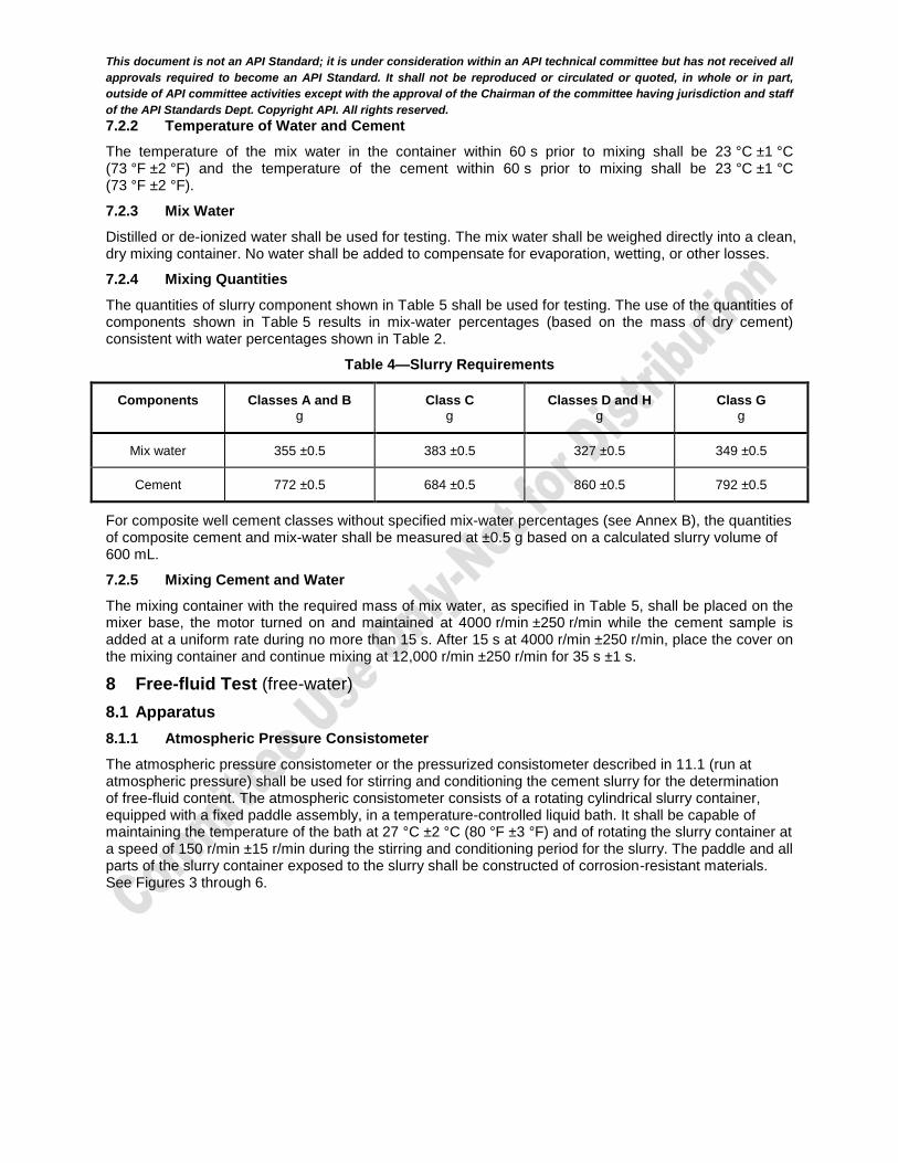
8.1.1 Atmospheric Pressure Consistometer
The atmospheric pressure consistometer or the pressurized consistometer described in 11.1 (run at atmospheric pressure) shall be used for stirring and conditioning the cement slurry for the determination of free-fluid content. The atmospheric consistometer consists of a rotating cylindrical slurry container, equipped with a fixed paddle assembly, in a temperature-controlled liquid bath. It shall be capable of maintaining the temperature of the bath at 27 °C ±2 °C (80 °F ±3 °F) and of rotating the slurry container at a speed of 150 r/min ±15 r/min during the stirring and conditioning period for the slurry. The paddle and all parts of the slurry container exposed to the slurry shall be constructed of corrosion-resistant materials. See Figures 3 through 6.

This document is not an API Standard; it is under consideration within an API technical committee but has not received all
approvals required to become an API Standard. It shall not be reproduced or circulated or quoted, in whole or in part,
outside of API committee activities except with the approval of the Chairman of the committee having jurisdiction and staff
of the API Standards Dept. Copyright API. All rights reserved.
Dimension in millimeters (inches) unless otherwise indicated.
Key
1 lid (see Figure 4) 3 Fill-level indicator groove
2 slurry container (see Figure 5) 4 paddle (see Figure 6)
NOTE Dimension provided for manufacturing reference only.
Figure 3—Container Assembly for an Atmospheric Pressure Consistometer
This document is not an API Standard; it is under consideration within an API technical committee but has not received all
approvals required to become an API Standard. It shall not be reproduced or circulated or quoted, in whole or in part,
outside of API committee activities except with the approval of the Chairman of the committee having jurisdiction and staff
of the API Standards Dept. Copyright API. All rights reserved.
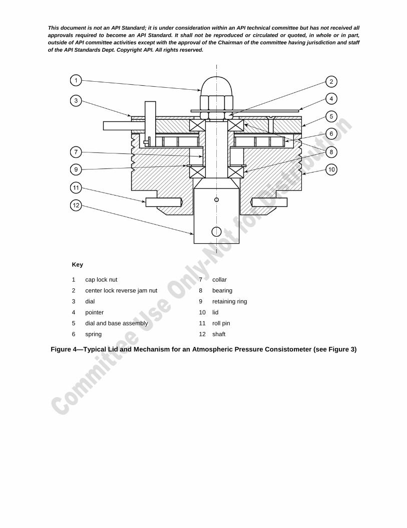
Key
1 cap lock nut
2 center lock reverse jam nut
3 dial
4 pointer
5 dial and base assembly
6 spring
7 collar
8 bearing
9 retaining ring
10 lid
11 roll pin
12 shaft
Figure 4—Typical Lid and Mechanism for an Atmospheric Pressure Consistometer (see Figure 3)
This document is not an API Standard; it is under consideration within an API technical committee but has not received all
approvals required to become an API Standard. It shall not be reproduced or circulated or quoted, in whole or in part,
outside of API committee activities except with the approval of the Chairman of the committee having jurisdiction and staff
of the API Standards Dept. Copyright API. All rights reserved.
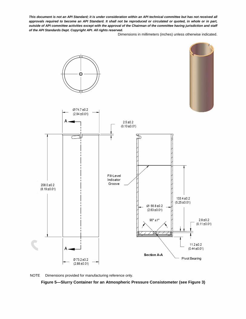
Dimensions in millimeters (inches) unless otherwise indicated.
NOTE Dimensions provided for manufacturing reference only.
Figure 5—Slurry Container for an Atmospheric Pressure Consistometer (see Figure 3)

This document is not an API Standard; it is under consideration within an API technical committee but has not received all
approvals required to become an API Standard. It shall not be reproduced or circulated or quoted, in whole or in part,
outside of API committee activities except with the approval of the Chairman of the committee having jurisdiction and staff
of the API Standards Dept. Copyright API. All rights reserved.
Dimensions in millimeters (inches) unless otherwise indicated.
NOTE 1 Paddle material: stainless steel, 1.0 mm ±0.1 mm (0.04 in. ±0.005 in.).
NOTE 2 Shaft material: stainless steel, 6.4 mm ±0.1 mm (0.25 in. ±0.005 in.).
NOTE 3 Dimensions provided for manufacturing reference only.
Figure 6—Paddle for an Atmospheric Pressure Consistometer (see Figure 3)
8.1.2 Balances
Balances shall meet the requirements set in 8.1.2.
This document is not an API Standard; it is under consideration within an API technical committee but has not received all
approvals required to become an API Standard. It shall not be reproduced or circulated or quoted, in whole or in part,
outside of API committee activities except with the approval of the Chairman of the committee having jurisdiction and staff
of the API Standards Dept. Copyright API. All rights reserved.
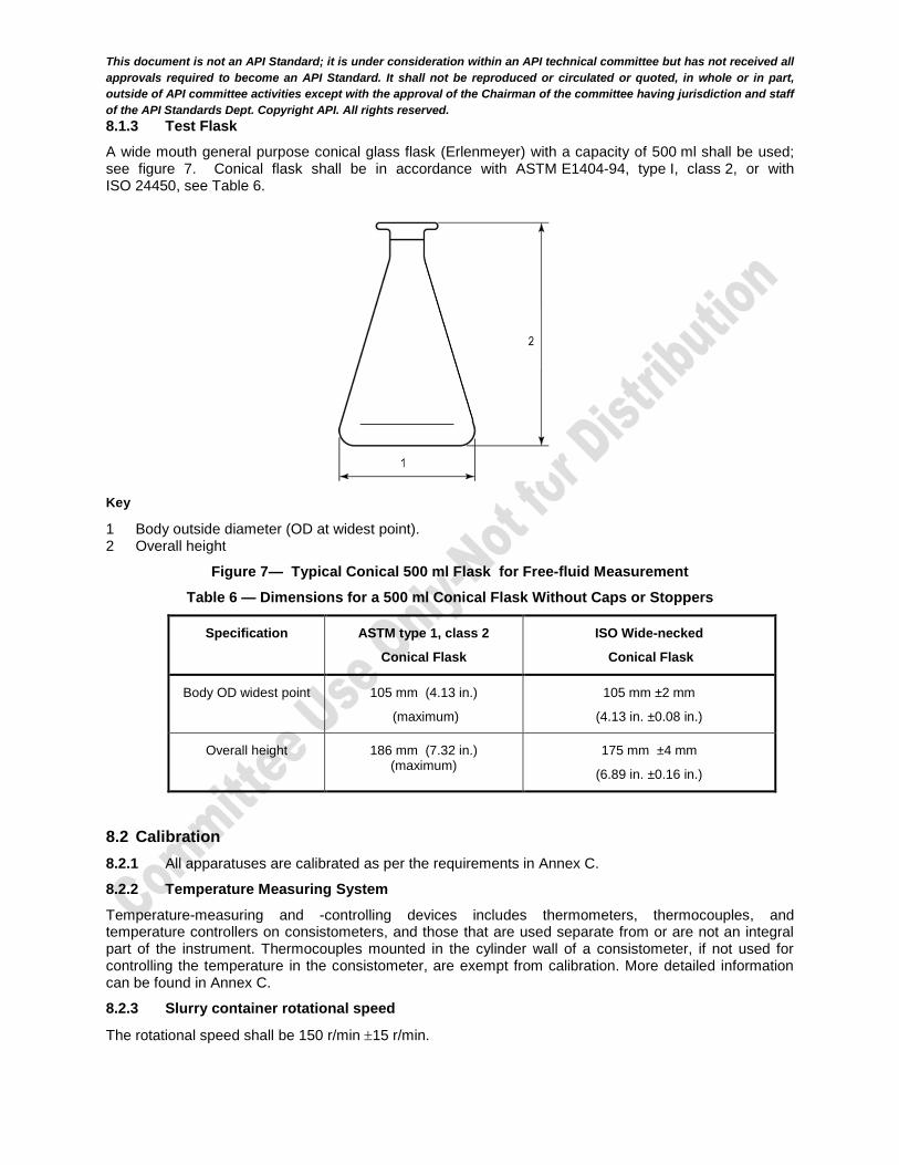
8.1.3 Test Flask
A wide mouth general purpose conical glass flask (Erlenmeyer) with a capacity of 500 ml shall be used; see figure 7. Conical flask shall be in accordance with ASTM E1404-94, type I, class 2, or with ISO 24450, see Table 6.
Key
1 Body outside diameter (OD at widest point). 2 Overall height
Figure 7— Typical Conical 500 ml Flask for Free-fluid Measurement
Table 6 — Dimensions for a 500 ml Conical Flask Without Caps or Stoppers
Specification ASTM type 1, class 2
Conical Flask
ISO Wide-necked
Conical Flask
Body OD widest point 105 mm (4.13 in.)
(maximum)
105 mm ±2 mm
(4.13 in. ±0.08 in.)
Overall height 186 mm (7.32 in.) (maximum)
175 mm ±4 mm
(6.89 in. ±0.16 in.)
8.2 Calibration
8.2.1 All apparatuses are calibrated as per the requirements in Annex C.
8.2.2 Temperature Measuring System
Temperature-measuring and -controlling devices includes thermometers, thermocouples, and temperature controllers on consistometers, and those that are used separate from or are not an integral part of the instrument. Thermocouples mounted in the cylinder wall of a consistometer, if not used for controlling the temperature in the consistometer, are exempt from calibration. More detailed information can be found in Annex C.
8.2.3 Slurry container rotational speed
The rotational speed shall be 150 r/min 15 r/min.
This document is not an API Standard; it is under consideration within an API technical committee but has not received all
approvals required to become an API Standard. It shall not be reproduced or circulated or quoted, in whole or in part,
outside of API committee activities except with the approval of the Chairman of the committee having jurisdiction and staff
of the API Standards Dept. Copyright API. All rights reserved.
8.2.4 Timer
The timer shall be accurate to within 5 seconds per hour.
8.3 Procedure
The following procedure describes how the free-fluid test shall be performed.
a) Prepare the slurry in accordance with the procedure in Section 8.
b) For an atmospheric consistometer, fill a clean and dry consistometer slurry container to the fill groove, or as per 11.3.2 for use of a pressurized consistometer.
c) Assemble the slurry container and associated parts, place them in the consistometer and start the motor according to the operating instructions of the manufacturer such that the interval between completion of mixing and starting of the consistometer shall not exceed 5 minutes.
d) Stir the slurry in the consistometer for a period of 20 min 30 s while the temperature of the slurry at
27 °C 2 °C (80 °F 3 °F) and atmospheric pressure throughout the stirring period.
e) Transfer 790 g 5 g of Class H slurry or 760 g 5 g of Class G slurry directly into the clean, dry 500 ml conical flask within 1 min of the end of stirring.
i) Record the actual mass transferred, mS.
ii) Seal the flask to prevent evaporation.
f) Set the slurry-filled flask on a surface that is nominally level and vibration-free.
i) The laboratory air temperature to which the slurry-filled flask is exposed shall be 23 °C 3 °C
(73 °F 5 °F).
ii) The temperature sensor for measuring air temperature shall meet the requirements of 9.2.2.
iii) Let the slurry filled flask remain undisturbed for a period of 2 hr 5 min.
g) Remove the supernatant fluid that has developed with a pipette or syringe at the end of the
2 hr 5 min period.
i) Measure the volume of supernatant fluid to an accuracy of 0.1 ml.
ii) Record the measure volume as “milliliters free-fluid, VFF.”
Convert the milliliters free-fluid to a percentage of starting slurry volume (400 ml depending on the recorded initial mass) and express that value as percent free-fluid.
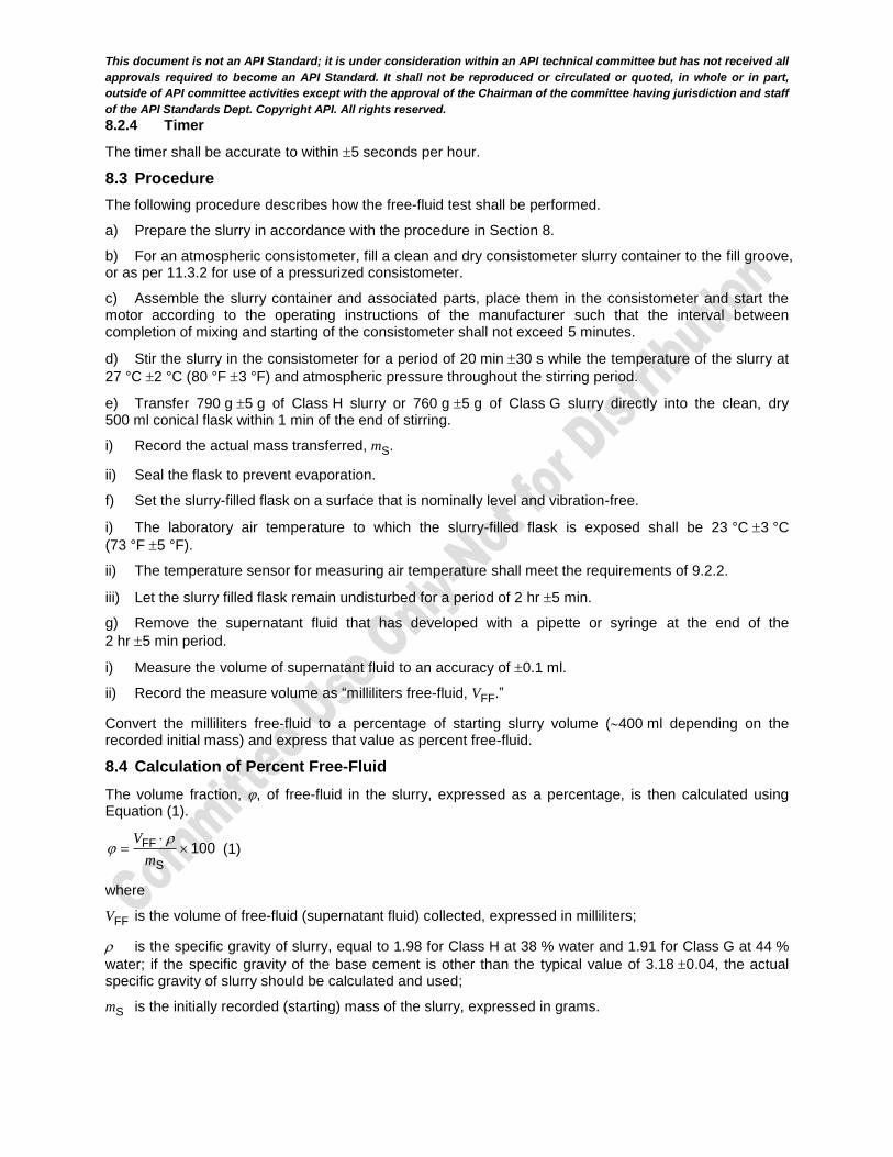
8.4 Calculation of Percent Free-Fluid
The volume fraction, , of free-fluid in the slurry, expressed as a percentage, is then calculated using Equation (1).
FF
S
100V
m
(1)
where
VFF is the volume of free-fluid (supernatant fluid) collected, expressed in milliliters;
is the specific gravity of slurry, equal to 1.98 for Class H at 38 % water and 1.91 for Class G at 44 %
water; if the specific gravity of the base cement is other than the typical value of 3.18 0.04, the actual specific gravity of slurry should be calculated and used;
mS is the initially recorded (starting) mass of the slurry, expressed in grams.
This document is not an API Standard; it is under consideration within an API technical committee but has not received all
approvals required to become an API Standard. It shall not be reproduced or circulated or quoted, in whole or in part,
outside of API committee activities except with the approval of the Chairman of the committee having jurisdiction and staff
of the API Standards Dept. Copyright API. All rights reserved.
EXAMPLE Calculation of percent free-fluid:
mS 791.7 g
VFF 15.1 ml
1.98 g/cm3 (Class H)
[(15.1 ml 1.98g/cm3 )/ 791.7 g] x 100
3.78 %
NOTE Milliliters and cubic centimeters are equal and interchangeable.
8.5 Acceptance Requirements
The free-fluid for classes G and H well cements shall not exceed 5.9 % of the volume of the slurry.
9 Compressive Strength Tests
9.1 Apparatus
9.1.1 All apparatuses are calibrated as per the requirements in Annex C.
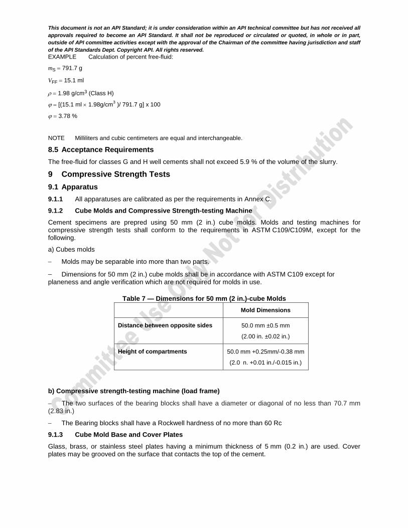
9.1.2 Cube Molds and Compressive Strength-testing Machine
Cement specimens are prepred using 50 mm (2 in.) cube molds. Molds and testing machines for compressive strength tests shall conform to the requirements in ASTM C109/C109M, except for the following.
a) Cubes molds
Molds may be separable into more than two parts.
Dimensions for 50 mm (2 in.) cube molds shall be in accordance with ASTM C109 except for planeness and angle verification which are not required for molds in use.
Table 7 — Dimensions for 50 mm (2 in.)-cube Molds Mold Dimensions
Distance between opposite sides 50.0 mm ±0.5 mm
(2.00 in. ±0.02 in.)
Height of compartments 50.0 mm +0.25mm/-0.38 mm
(2.0 n. +0.01 in./-0.015 in.)
b) Compressive strength-testing machine (load frame)
The two surfaces of the bearing blocks shall have a diameter or diagonal of no less than 70.7 mm (2.83 in.)
The Bearing blocks shall have a Rockwell hardness of no more than 60 Rc
9.1.3 Cube Mold Base and Cover Plates
Glass, brass, or stainless steel plates having a minimum thickness of 5 mm (0.2 in.) are used. Cover plates may be grooved on the surface that contacts the top of the cement.
This document is not an API Standard; it is under consideration within an API technical committee but has not received all
approvals required to become an API Standard. It shall not be reproduced or circulated or quoted, in whole or in part,
outside of API committee activities except with the approval of the Chairman of the committee having jurisdiction and staff
of the API Standards Dept. Copyright API. All rights reserved.
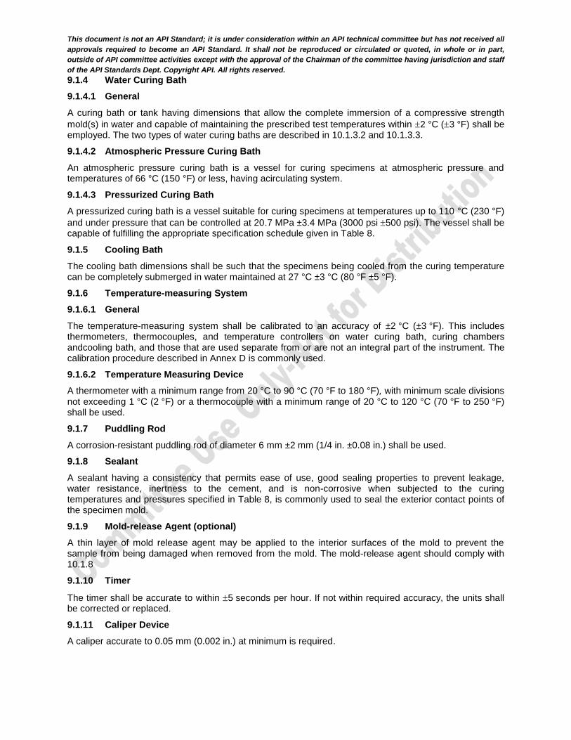
9.1.4 Water Curing Bath
9.1.4.1 General
A curing bath or tank having dimensions that allow the complete immersion of a compressive strength
mold(s) in water and capable of maintaining the prescribed test temperatures within 2 °C (3 °F) shall be employed. The two types of water curing baths are described in 10.1.3.2 and 10.1.3.3.
9.1.4.2 Atmospheric Pressure Curing Bath
An atmospheric pressure curing bath is a vessel for curing specimens at atmospheric pressure and temperatures of 66 °C (150 °F) or less, having acirculating system.
9.1.4.3 Pressurized Curing Bath
A pressurized curing bath is a vessel suitable for curing specimens at temperatures up to 110 °C (230 °F)
and under pressure that can be controlled at 20.7 MPa ±3.4 MPa (3000 psi 500 psi). The vessel shall be capable of fulfilling the appropriate specification schedule given in Table 8.
9.1.5 Cooling Bath
The cooling bath dimensions shall be such that the specimens being cooled from the curing temperature can be completely submerged in water maintained at 27 °C ±3 °C (80 °F ±5 °F).
9.1.6 Temperature-measuring System
9.1.6.1 General
The temperature-measuring system shall be calibrated to an accuracy of ±2 °C (±3 °F). This includes thermometers, thermocouples, and temperature controllers on water curing bath, curing chambers andcooling bath, and those that are used separate from or are not an integral part of the instrument. The calibration procedure described in Annex D is commonly used.
9.1.6.2 Temperature Measuring Device
A thermometer with a minimum range from 20 °C to 90 °C (70 °F to 180 °F), with minimum scale divisions not exceeding 1 °C (2 °F) or a thermocouple with a minimum range of 20 °C to 120 °C (70 °F to 250 °F) shall be used.
9.1.7 Puddling Rod
A corrosion-resistant puddling rod of diameter 6 mm ±2 mm (1/4 in. ±0.08 in.) shall be used.
9.1.8 Sealant
A sealant having a consistency that permits ease of use, good sealing properties to prevent leakage, water resistance, inertness to the cement, and is non-corrosive when subjected to the curing temperatures and pressures specified in Table 8, is commonly used to seal the exterior contact points of the specimen mold.
9.1.9 Mold-release Agent (optional)
A thin layer of mold release agent may be applied to the interior surfaces of the mold to prevent the sample from being damaged when removed from the mold. The mold-release agent should comply with 10.1.8
9.1.10 Timer
The timer shall be accurate to within 5 seconds per hour. If not within required accuracy, the units shall be corrected or replaced.
9.1.11 Caliper Device
A caliper accurate to 0.05 mm (0.002 in.) at minimum is required.

This document is not an API Standard; it is under consideration within an API technical committee but has not received all
approvals required to become an API Standard. It shall not be reproduced or circulated or quoted, in whole or in part,
outside of API committee activities except with the approval of the Chairman of the committee having jurisdiction and staff
of the API Standards Dept. Copyright API. All rights reserved.
9.2 Procedure
9.2.1 Preparation of Molds
The base of assembled molds shall be watertight. The interior faces of the molds and the contact surfaces of the plates shall be clean and dry, and may be lightly coated with release agent.
9.2.2 Preparation and Placement of Slurry
9.2.2.1 Slurry
The cement slurry shall be prepared in accordance with Section 8.
9.2.2.2 Placing Slurry in Molds
To prepare the sample, the following procedure shall be followed.
a) Place the slurry in the prepared molds in a layer approximately one-half of the mold depth. b) Place the slurry in all the specimen compartments before commencing the puddling operation.
c) Use the puddling rod to puddle the slurry in an evenly distributed pattern, 27 times per specimen. d) After puddling the layer, stir the remaining slurry by hand using a puddling rod or spatula to minimize segregation. e) Fill the molds to overflowing and puddle the same as for the first layer. f) After puddling, use a straight-edge to strike off the excess slurry level with the top of the mold. g) Discard specimens in molds that leak. h) Place a clean, dry cover plate on top of the mold.
No less than three specimens shall be used for each test determination.
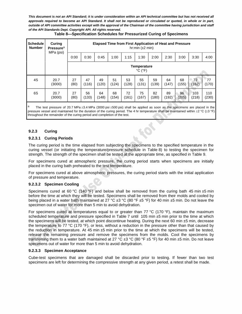
9.2.2.3 Pressure and Temperature Schedules
For classes A, B, C, G, and H cements, place the specimens in the water bath preheated to the final curing temperature for tests at atmospheric pressure, within 5 min after mixing (see Table 2).
For Class D cement, place the specimens in the pressure vessel in water at 27 °C ±3 °C (80 °F ±5 °F), and within 5 min after mixing, apply temperature and pressure according to Table 8.
This document is not an API Standard; it is under consideration within an API technical committee but has not received all
approvals required to become an API Standard. It shall not be reproduced or circulated or quoted, in whole or in part,
outside of API committee activities except with the approval of the Chairman of the committee having jurisdiction and staff
of the API Standards Dept. Copyright API. All rights reserved.
Table 8—Specification Schedules for Pressurized Curing of Specimens
Schedule Number
Curing
Pressurea
MPa (psi)
Elapsed Time from First Application of Heat and Pressure
hr:min (±2 min)
0:00 0:30 0:45 1:00 1:15 1:30 2:00 2:30 3:00 3:30 4:00
Temperature
°C (°F)
4S 20.7 (3000)
27 (80)
47 (116)
49 (120)
51 (124)
53 (128)
55 (131)
59 (139)
64 (147)
68 (155)
72 (162)
77 (170)
6S 20.7 (3000)
27 (80)
56 (133)
64 (148)
68 (154)
72 (161)
75 (167)
82 (180)
89 (192)
96 (205)
103 (218)
110 (230)
a The test pressure of 20.7 MPa 3.4 MPa (3000 psi 500 psi) shall be applied as soon as the specimens are placed in the
pressure vessel and maintained for the duration of the curing period. The 4 hr temperature shall be maintained within 2 °C (3 °F) throughout the remainder of the curing period and completion of the test.
9.2.3 Curing
9.2.3.1 Curing Periods
The curing period is the time elapsed from subjecting the specimens to the specified temperature in the curing vessel (or initiating the temperature/pressure schedule in Table 8) to testing the specimen for strength. The strength of the specimen shall be tested at the appropriate time, as specified in Table 9.
For specimens cured at atmospheric pressure, the curing period starts when specimens are initially placed in the curing bath preheated to the test temperature.
For specimens cured at above atmospheric pressures, the curing period starts with the initial application of pressure and temperature.
9.2.3.2 Specimen Cooling
Specimens cured at 60 °C (140 °F) and below shall be removed from the curing bath 45 min ±5 min before the time at which they will be tested. Specimens shall be removed from their molds and cooled by being placed in a water bath maintained at 27 °C ±3 °C (80 °F ±5 °F) for 40 min ±5 min. Do not leave the specimen out of water for more than 5 min to avoid dehydration.
For specimens cured at temperatures equal to or greater than 77 °C (170 °F), maintain the maximum scheduled temperature and pressure specified in Table 7 until 105 min ±5 min prior to the time at which the specimens will be tested, at which point discontinue heating. During the next 60 min ±5 min, decrease the temperature to 77 °C (170 °F), or less, without a reduction in the pressure other than that caused by the reduction in temperature. At 45 min ±5 min prior to the time at which the specimens will be tested, release the remaining pressure and remove the specimens from the molds. Cool the specimens by transferring them to a water bath maintained at 27 °C ±3 °C (80 °F ±5 °F) for 40 min ±5 min. Do not leave specimens out of water for more than 5 min to avoid dehydration.
9.2.3.3 Specimen Acceptance
Cube-test specimens that are damaged shall be discarded prior to testing. If fewer than two test specimens are left for determining the compressive strength at any given period, a retest shall be made.
This document is not an API Standard; it is under consideration within an API technical committee but has not received all
approvals required to become an API Standard. It shall not be reproduced or circulated or quoted, in whole or in part,
outside of API committee activities except with the approval of the Chairman of the committee having jurisdiction and staff
of the API Standards Dept. Copyright API. All rights reserved.
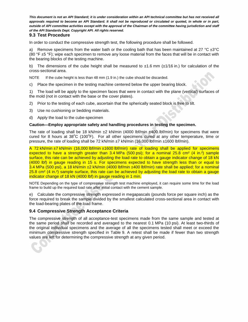
9.3 Test Procedure
In order to conduct the compressive strength test, the following procedure shall be followed.
a) Remove specimens from the water bath or the cooling bath that has been maintained at 27 °C ±3°C (80 °F ±5 °F); wipe each specimen to remove any loose material from the faces that will be in contact with the bearing blocks of the testing machine.
b) The dimensions of the cube height shall be measured to ±1.6 mm (±1/16 in.) for calculation of the cross-sectional area.
NOTE If the cube height is less than 48 mm (1.9 in.) the cube should be discarded.
c) Place the specimen in the testing machine centered below the upper bearing block.
1) The load will be apply to the specimen faces that were in contact with the plane (vertical) surfaces of the mold (not in contact with the base or the cover plates).
2) Prior to the testing of each cube, ascertain that the spherically seated block is free to tilt.
3) Use no cushioning or bedding materials.
d) Apply the load to the cube-specimen
Caution—Employ appropriate safety and handling procedures in testing the specimen.
The rate of loading shall be 18 kN/min ±2 kN/min (4000 lbf/min ±400 lbf/min) for specimens that were cured for 8 hours at 38
oC (100
oF). For all other specimens cured at any other temperature, time or
pressure, the rate of loading shall be 72 kN/min ±7 kN/min (16,000 lbf/min ±1600 lbf/min).
A 72 kN/min ±7 kN/min (16,000 lbf/min ±1600 lbf/min) rate of loading shall be applied for specimens expected to have a strength greater than 3.4 MPa (500 psi); for a nominal 25.8 cm² (4 in.²) sample surface, this rate can be achieved by adjusting the load rate to obtain a gauge indicator change of 18 kN (4000 lbf) in gauge reading in 15 s. For specimens expected to have strength less than or equal to 3.4 MPa (500 psi), a 18 kN/min ±2 kN/min (4000 lbf/min ±400 lbf/min) rate shall be applied; for a nominal 25.8 cm² (4 in.²) sample surface, this rate can be achieved by adjusting the load rate to obtain a gauge indicator change of 18 kN (4000 lbf) in gauge reading in 1 min.
NOTE Depending on the type of compressive strength test machine employed, it can require some time for the load frame to build up the required load rate after initial contact with the cement sample.
e) Calculate the compressive strength expressed in megapascals (pounds force per square inch) as the force required to break the sample divided by the smallest calculated cross-sectional area in contact with the load-bearing plates of the load frame.
9.4 Compressive Strength Acceptance Criteria
The compressive strength of all acceptance-test specimens made from the same sample and tested at the same period shall be recorded and averaged to the nearest 0.1 MPa (10 psi). At least two-thirds of the original individual specimens and the average of all the specimens tested shall meet or exceed the minimum compressive strength specified in Table 9. A retest shall be made if fewer than two strength values are left for determining the compressive strength at any given period.

This document is not an API Standard; it is under consideration within an API technical committee but has not received all
approvals required to become an API Standard. It shall not be reproduced or circulated or quoted, in whole or in part,
outside of API committee activities except with the approval of the Chairman of the committee having jurisdiction and staff
of the API Standards Dept. Copyright API. All rights reserved.
Table 9—Compressive Strength Specification Requirements
Cement Class Schedule number
Final curing
temperaturea
°C (°F)
Curing pressureb
MPa (psi)
Minimum Compressive Strength at Indicated Curing Period
8 hr 15 minc
MPa (psi)
24 hr 15 minc
MPa (psi)
A — 38 (100) atmospheric 1.7 (250) 12.4 (1800)
B — 38 (100) atmospheric 1.4 (200) 10.3 (1500)
C — 38 (100) atmospheric 2.1 (300) 13.8 (2000)
D
4S 77 (170) 20.7 (3000) NRd 6.9 (1000)
6S 110 (230) 20.7 (3000) 3.4 (500) 13.8 (2000)
G, H
— 38 (100) atmospheric 2.1 (300) NR
— 60 (140) atmospheric 10.3 (1500) NR
a The curing temperature shall be maintained at the indicated temperature 2 °C (3 °F).
b The test pressure shall be applied as soon as specimens are placed in the pressure vessel, and maintained at the given
pressure within 3.4 MPa (500 psi) for schedules 4S and 6S.
c Time includes cooling time of 45 min ±5 min.
d NR indicates “no requirement.”
10 Thickenning-time Tests
10.1 Apparatus
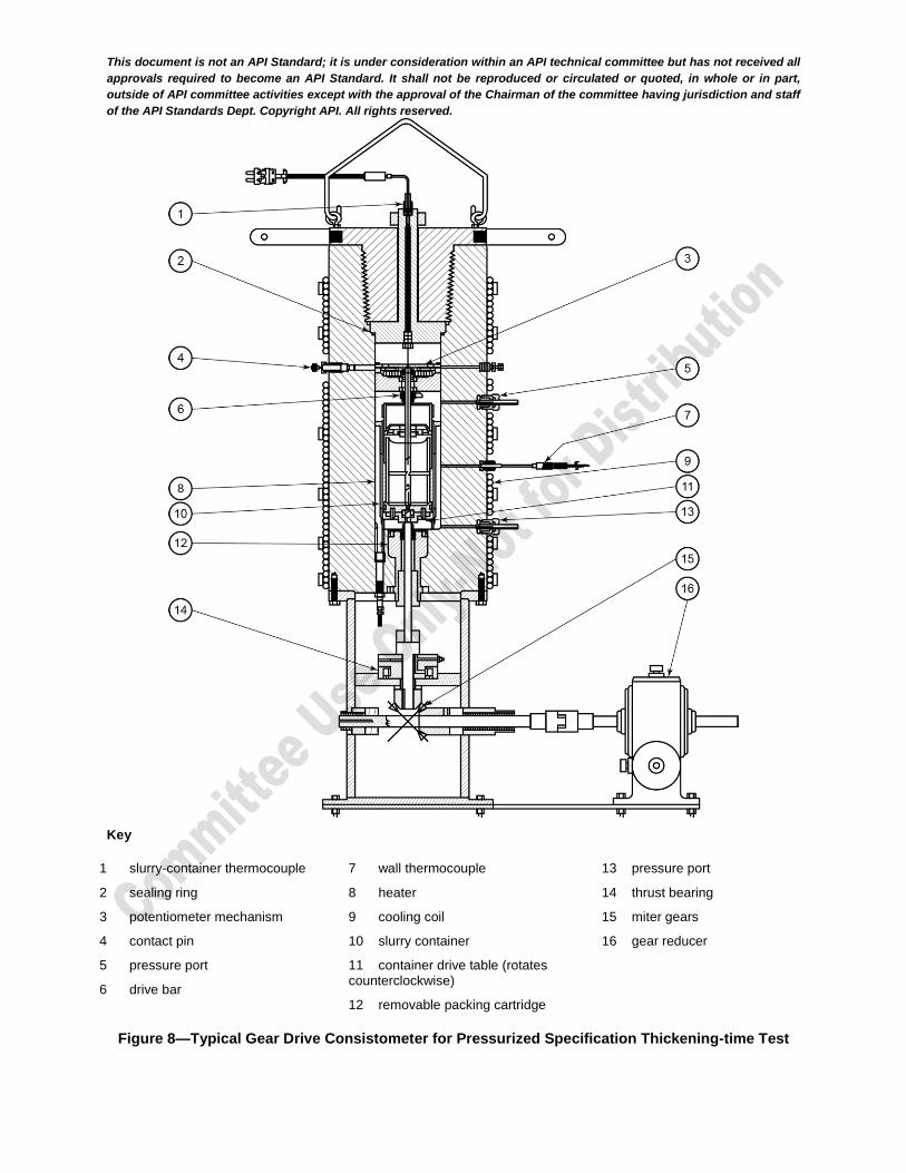
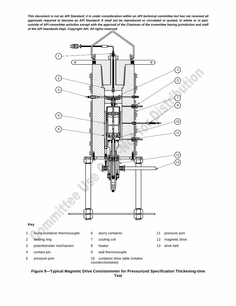
A pressurized consistometer (see Figures 8 and 9) shall consist of a rotating cylindrical slurry container (see Figures 10 and 11) equipped with a stationary paddle assembly (see Figure 12) enclosed in a pressure vessel capable of withstanding the pressures and temperatures described in Tables 10 through 12.
A heating system capable of raising the temperature of this oil bath at the rate of at least 3 °C/min (5 °F/min) is required. A temperature-measuring system shall be provided for determining and controlling the temperature of the cement slurry (centerline). The slurry container is rotated at a speed of
150 r/min 15 r/min. The consistency of the slurry (see 11.2.2.1) shall be measured. The paddle and all parts of the slurry container exposed to the slurry shall be constructed according to the dimensions given in Figures 10 through 12.
The space between the slurry container and the walls of the pressure vessel shall be completely filled with white mineral or synthetic oil. The selected oil shall safely allow the required 3 °C / min heat-up rate.
This document is not an API Standard; it is under consideration within an API technical committee but has not received all
approvals required to become an API Standard. It shall not be reproduced or circulated or quoted, in whole or in part,
outside of API committee activities except with the approval of the Chairman of the committee having jurisdiction and staff
of the API Standards Dept. Copyright API. All rights reserved.
Key
1 slurry-container thermocouple
2 sealing ring
3 potentiometer mechanism
4 contact pin
5 pressure port
6 drive bar
7 wall thermocouple
8 heater
9 cooling coil
10 slurry container
11 container drive table (rotates counterclockwise)
12 removable packing cartridge
13 pressure port
14 thrust bearing
15 miter gears
16 gear reducer
Figure 8—Typical Gear Drive Consistometer for Pressurized Specification Thickening-time Test
This document is not an API Standard; it is under consideration within an API technical committee but has not received all
approvals required to become an API Standard. It shall not be reproduced or circulated or quoted, in whole or in part,
outside of API committee activities except with the approval of the Chairman of the committee having jurisdiction and staff
of the API Standards Dept. Copyright API. All rights reserved.
Key
1 slurry-container thermocouple
2 sealing ring
3 potentiometer mechanism
4 contact pin
5 pressure port
6 slurry container
7 cooling coil
8 heater
9 wall thermocouple
10 container drive table (rotates counterclockwise)
11 pressure port
12 magnetic drive
13 drive belt
Figure 9—Typical Magnetic Drive Consistometer for Pressurized Specification Thickening-time Test
This document is not an API Standard; it is under consideration within an API technical committee but has not received all
approvals required to become an API Standard. It shall not be reproduced or circulated or quoted, in whole or in part,
outside of API committee activities except with the approval of the Chairman of the committee having jurisdiction and staff
of the API Standards Dept. Copyright API. All rights reserved.
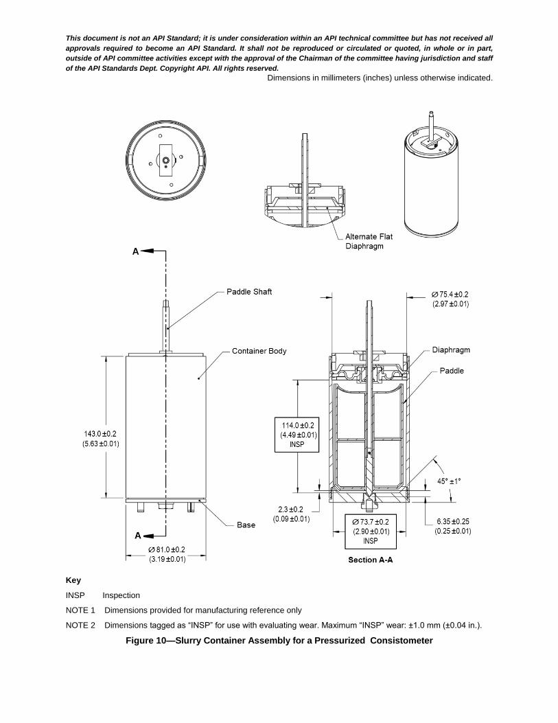
Dimensions in millimeters (inches) unless otherwise indicated.
Key
INSP Inspection
NOTE 1 Dimensions provided for manufacturing reference only
NOTE 2 Dimensions tagged as “INSP” for use with evaluating wear. Maximum “INSP” wear: ±1.0 mm (±0.04 in.).
Figure 10—Slurry Container Assembly for a Pressurized Consistometer

This document is not an API Standard; it is under consideration within an API technical committee but has not received all
approvals required to become an API Standard. It shall not be reproduced or circulated or quoted, in whole or in part,
outside of API committee activities except with the approval of the Chairman of the committee having jurisdiction and staff
of the API Standards Dept. Copyright API. All rights reserved.
Dimensions in millimeters (inches) unless otherwise indicated.
Key
INSP Inspection
NOTE 1 Dimensions provided for manufacturing reference only
NOTE 2 Dimensions tagged as “INSP” for use with evaluating wear. Maximum “INSP” wear: ±1.0 mm (±0.04 in.).
Figure 11—Slurry Container Assembly for a High Temperature Pressurized Consistometer

This document is not an API Standard; it is under consideration within an API technical committee but has not received all
approvals required to become an API Standard. It shall not be reproduced or circulated or quoted, in whole or in part,
outside of API committee activities except with the approval of the Chairman of the committee having jurisdiction and staff
of the API Standards Dept. Copyright API. All rights reserved.
Dimensions in millimeters (inches) unless otherwise indicated.
Key
INSP Inspection
TYP typical
NOTE 1 Paddle material: stainless steel, typical thickness 1.6 mm ±0.1 mm (0.062 in. ±0.005 in.). NOTE 2 Taper all leading edges out and down and round all trailing edges, typical radius 0.75 mm (0.03 in.). NOTE 3 Rotate the slurry container counter clockwise when viewed from top of paddle. NOTE 4 Dimensions provided for manufacturing reference only NOTE 5 Dimensions tagged as “INSP” for use with evaluating paddle wear. Maximum “INSP” wear: ±1.0 mm (±0.04 in.).
a) Paddle for a Pressurized Slurry Container
This document is not an API Standard; it is under consideration within an API technical committee but has not received all
approvals required to become an API Standard. It shall not be reproduced or circulated or quoted, in whole or in part,
outside of API committee activities except with the approval of the Chairman of the committee having jurisdiction and staff
of the API Standards Dept. Copyright API. All rights reserved.
Dimensions in millimeters (inches) unless otherwise indicated.
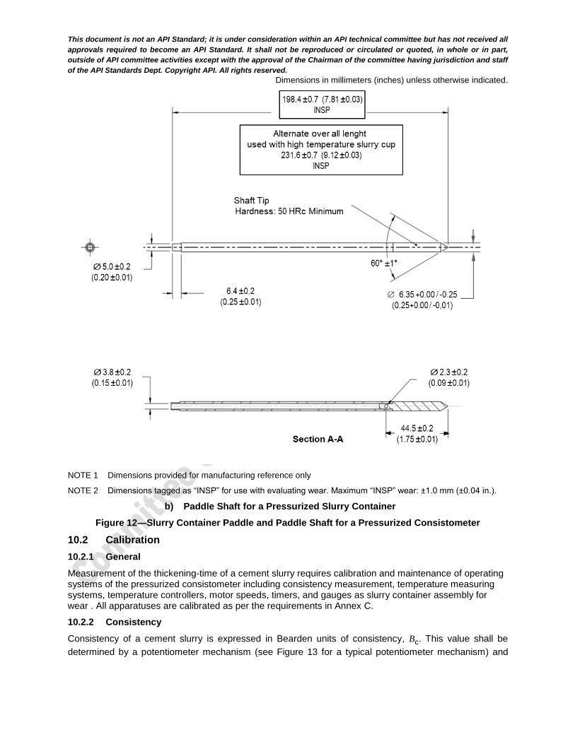
NOTE 1 Dimensions provided for manufacturing reference only
NOTE 2 Dimensions tagged as “INSP” for use with evaluating wear. Maximum “INSP” wear: ±1.0 mm (±0.04 in.).
b) Paddle Shaft for a Pressurized Slurry Container
Figure 12—Slurry Container Paddle and Paddle Shaft for a Pressurized Consistometer
10.2 Calibration
10.2.1 General
Measurement of the thickening-time of a cement slurry requires calibration and maintenance of operating systems of the pressurized consistometer including consistency measurement, temperature measuring systems, temperature controllers, motor speeds, timers, and gauges as slurry container assembly for wear . All apparatuses are calibrated as per the requirements in Annex C.
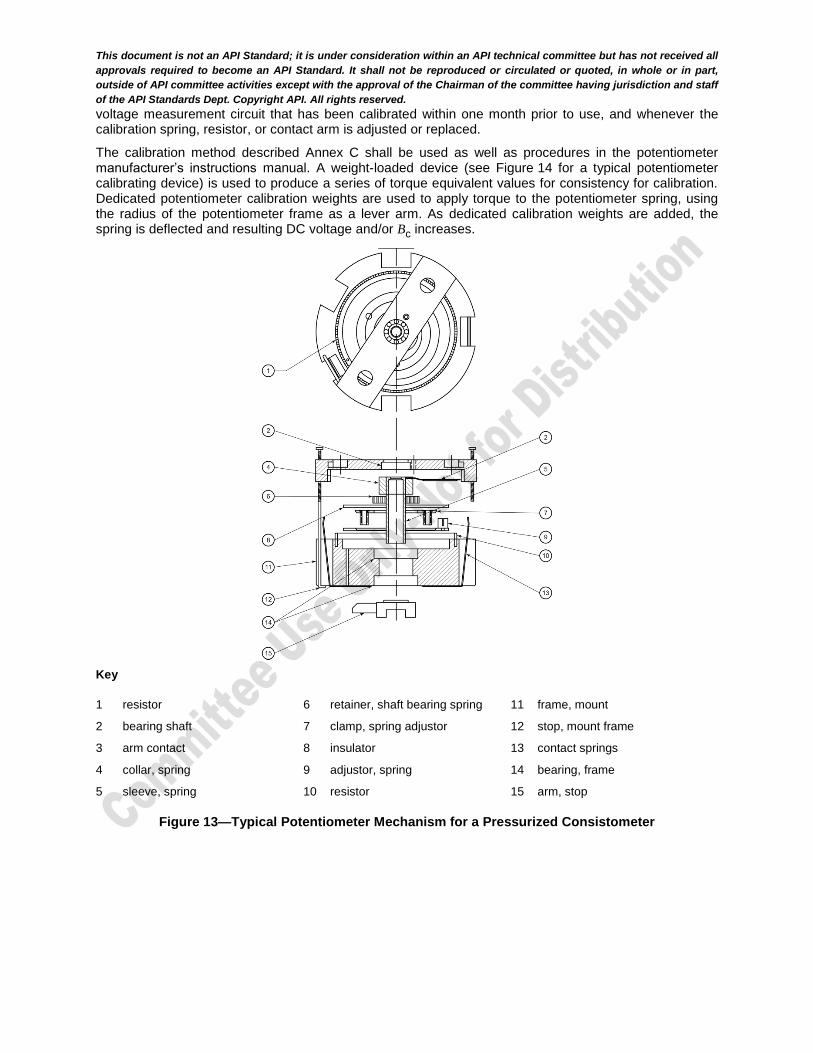
10.2.2 Consistency
Consistency of a cement slurry is expressed in Bearden units of consistency, Bc. This value shall be
determined by a potentiometer mechanism (see Figure 13 for a typical potentiometer mechanism) and
This document is not an API Standard; it is under consideration within an API technical committee but has not received all
approvals required to become an API Standard. It shall not be reproduced or circulated or quoted, in whole or in part,
outside of API committee activities except with the approval of the Chairman of the committee having jurisdiction and staff
of the API Standards Dept. Copyright API. All rights reserved.
voltage measurement circuit that has been calibrated within one month prior to use, and whenever the calibration spring, resistor, or contact arm is adjusted or replaced.
The calibration method described Annex C shall be used as well as procedures in the potentiometer manufacturer’s instructions manual. A weight-loaded device (see Figure 14 for a typical potentiometer calibrating device) is used to produce a series of torque equivalent values for consistency for calibration. Dedicated potentiometer calibration weights are used to apply torque to the potentiometer spring, using the radius of the potentiometer frame as a lever arm. As dedicated calibration weights are added, the spring is deflected and resulting DC voltage and/or Bc increases.
Key
1 resistor
2 bearing shaft
3 arm contact
4 collar, spring
5 sleeve, spring
6 retainer, shaft bearing spring
7 clamp, spring adjustor
8 insulator
9 adjustor, spring
10 resistor
11 frame, mount
12 stop, mount frame
13 contact springs
14 bearing, frame
15 arm, stop
Figure 13—Typical Potentiometer Mechanism for a Pressurized Consistometer

This document is not an API Standard; it is under consideration within an API technical committee but has not received all
approvals required to become an API Standard. It shall not be reproduced or circulated or quoted, in whole or in part,
outside of API committee activities except with the approval of the Chairman of the committee having jurisdiction and staff
of the API Standards Dept. Copyright API. All rights reserved.
Figure 14—Typical Potentiometer Calibrating Device
10.2.3 Temperature-measuring System
The temperature-measuring system shall be calibrated to an accuracy of ±1 °C (±2 °F). The procedure
described in Annex D is commonly used.
10.2.4 Motor Speed
The motor shall rotate the slurry container at 150 r/min 15 r/min.
10.2.5 Timer
Timers shall be accurate to within ±5 seconds per hour. If not within required accuracy, the units shall be
adjusted or replaced..
10.2.6 Pressure-measuring System
Calibration shall be conducted against a dead-weight tester or master gauge or when a pressure transducer or gauge is replaced. For application of the standard high pressure-measuring system[>17 MPA (2500 psi)] shall be calibrated at 17 MPa, 34 MPa, and 52 MPa (2500 psi, 5000 psi, and 7500 psi).
Maximum allowable error is 1 % of full range or one minimum gauge increment, whichever is greater.
10.2.7 Slurry Container Assembly
A caliper accurate to 0.05 mm (0.002 in.) at minimum is required to verify key dimensions (dimensions tagged as “INSP” on Figure 10 through 12) for wear of slurry container assembly for pressurized consistometer. IF slurry container shall be verified annually, paddle and paddle shaft shall be verified at least quarterly and/or each time a paddle/shaft is replaced.
10.3 Procedure
10.3.1 Operating Instructions
Detailed operating instructions developed by the operator, or furnished by the equipment manufacturer, are applicable for this method and shall be followed, provided they conform to the specifications contained in this specification. Grease may be placed only on the threaded surfaces of the slurry container.
10.3.2 Assembly and Filling the Slurry Container
Inspect and assemble the slurry cup, prepare the slurry as per Clause 8, and fill the slurry container by the following steps:
This document is not an API Standard; it is under consideration within an API technical committee but has not received all
approvals required to become an API Standard. It shall not be reproduced or circulated or quoted, in whole or in part,
outside of API committee activities except with the approval of the Chairman of the committee having jurisdiction and staff
of the API Standards Dept. Copyright API. All rights reserved.
a) ensure the cup and threads are clean;
b) inspect the diaphragm and replace it if it is damaged;
c) assemble the paddle shaft assembly and diaphragm with diaphragm support ring and back-up plate and secure them in the cup sleeve with the flange ring (the paddle and inside of cup sleeve should not be greased as some greases have been found to affect thickening-time results). Ensure the tapered side of the diaphragm support ring is against the diaphragm for the best seal;
d) assemble the base and center plug (pivot bearing) and make sure the paddle turns freely;
e) remove the base and pivot bearing. Grease the threads of the cup on the base end to ease removal following the test. Grease the threads of the center plug to ease removal;
f) with the base end of the slurry container up, prepare the slurry as in Clause 8 and fill to the top or leaving two to three threads showing;
g) strike the cup and remove any air that rises to the top of the slurry;
h) install the base until slurry is extruded through the center hole;
i) install the center plug (pivot bearing) into the container and tighten it until both the plug and base are tight in the container;
j) rinse all cement from the outer surfaces and dry them; and
k) recheck the paddle to ensure it turns smoothly.
10.3.3 Initiation of Test
11.3.3.1 Place the filled slurry container on the drive table in the pressure vessel, start rotation of the slurry container and secure the potentiometer mechanism or other suitable device for measuring consistency so as to engage the paddle shaft drive bar. Begin filling the vessel with oil. The paddle shaft should not be rotating.
NOTE Some consistometers fill with oil faster than others. Begin filling those that fill quickly after the head assembly has been secured in the pressure vessel.
11.3.3.2 Secure the head assembly in the pressure vessel, insert the thermocouple through its fitting, and partially engage the threads. After the pressure vessel is completely filled with oil, tighten the threads of the thermocouple.
11.3.3.3 Begin the thickening-time test by applying the initial pressure and starting the temperature ramp. No more than 5 min should have elapsed after cessation of mixing of the slurry as defined in 8.2.5 and the beginning of the test.
10.3.4 Temperature and Pressure Control
During the test period, increase the temperature and pressure of the cement slurry in the slurry container in accordance with the appropriate specification schedule given in Tables 10, 11 or 12. During the pressure and temperature ramp of schedules 4, 5, and 6, the temperature and pressure shall be maintained within ±3 °C (±5 °F) and ±2 MPa (±300 psi), respectively, of the appropriate elapsed time versus temperature and pressure target. Within 10 min after the end of the ramp, the temperature and pressure shall be within
±1 °C (±2 °F) and ±0.7 MPa (±100 psi), respectively, of the specified values. Determine the temperature of
the cement slurry for specification testing by the use of a temperature-measuring device located in the center of the sample container.
The tip of the thermocouple shall be vertically positioned within the paddle shaft in the slurry cup in such a way that it is between 45 mm (1.77 in.) and 89 mm (3.5 in.) above the inside of the base of the sample container. As there are many models of consistometers having different dimensions, care shall be taken to ensure that the thermocouple used is compatible with the consistometer and that the position of the tip of the thermocouple is in the correct location specified above.

This document is not an API Standard; it is under consideration within an API technical committee but has not received all
approvals required to become an API Standard. It shall not be reproduced or circulated or quoted, in whole or in part,
outside of API committee activities except with the approval of the Chairman of the committee having jurisdiction and staff
of the API Standards Dept. Copyright API. All rights reserved.
Table 10—Schedule 4: Specification Thickening-time Test for Classes A, B, C and D Cement
Elapsed Time
min
Pressure
MPa (psi)
Temperature
°C (°F)
0 5.2 (750) 27 (80)
2 7.6 (1100) 28 (83)
4 9.7 (1400) 31 (87)
6 11.7 (1700) 32 (90)
8 13.8 (2000) 34 (93)
10 15.9 (2300) 36 (97)
12 17.9 (2600) 38 (100)
14 20.0 (2900) 39 (103)
16 22.1 (3200) 41 (106)
18 24.8 (3600) 43 (110)
20 26.7 (3870) 45 (113)
This document is not an API Standard; it is under consideration within an API technical committee but has not received all
approvals required to become an API Standard. It shall not be reproduced or circulated or quoted, in whole or in part,
outside of API committee activities except with the approval of the Chairman of the committee having jurisdiction and staff
of the API Standards Dept. Copyright API. All rights reserved.
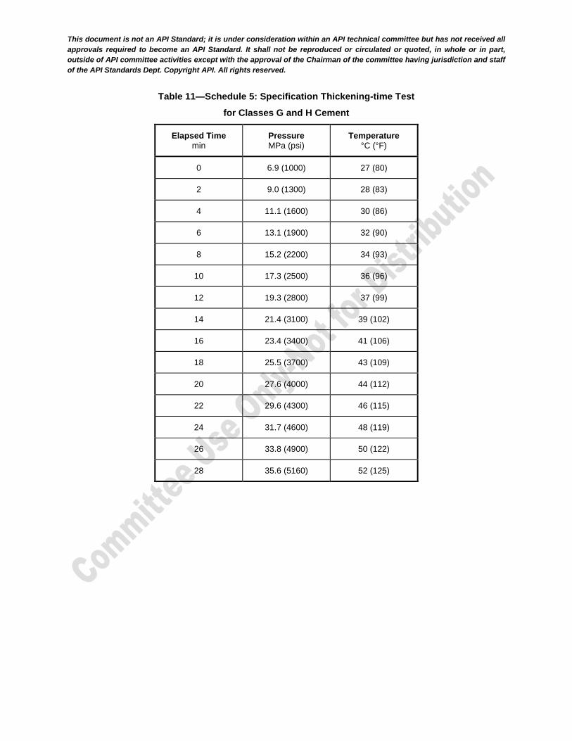
Table 11—Schedule 5: Specification Thickening-time Test
for Classes G and H Cement
Elapsed Time
min
Pressure
MPa (psi)
Temperature
°C (°F)
0 6.9 (1000) 27 (80)
2 9.0 (1300) 28 (83)
4 11.1 (1600) 30 (86)
6 13.1 (1900) 32 (90)
8 15.2 (2200) 34 (93)
10 17.3 (2500) 36 (96)
12 19.3 (2800) 37 (99)
14 21.4 (3100) 39 (102)
16 23.4 (3400) 41 (106)
18 25.5 (3700) 43 (109)
20 27.6 (4000) 44 (112)
22 29.6 (4300) 46 (115)
24 31.7 (4600) 48 (119)
26 33.8 (4900) 50 (122)
28 35.6 (5160) 52 (125)

This document is not an API Standard; it is under consideration within an API technical committee but has not received all
approvals required to become an API Standard. It shall not be reproduced or circulated or quoted, in whole or in part,
outside of API committee activities except with the approval of the Chairman of the committee having jurisdiction and staff
of the API Standards Dept. Copyright API. All rights reserved.
Table 12—Schedule 6: Specification Thickening-time Test
for Class D Cement
Elapsed Time
min
Pressure
MPa (psi)
Temperature
°C (°F)
0 8.6 (1250) 27 (80)
2 11.0 (1600) 29 (84)
4 13.1 (1900) 31 (87)
6 15.9 (2300) 33 (91)
8 17.9 (2600) 34 (94)
10 20.7 (3000) 37 (98)
12 22.8 (3300) 38 (101)
14 25.5 (3700) 41 (105)
16 27.6 (4000) 42 (108)
18 30.3 (4400) 44 (112)
20 32.4 (4700) 47 (116)
22 35.2 (5100) 48 (119)
24 37.2 (5400) 51 (123)
26 39.3 (5700) 52 (126)
28 42.1 (6100) 54 (130)
30 44.1 (6400) 56 (133)
32 46.9 (6800) 58 (137)
34 49.0 (7100) 60 (140)
36 51.6 (7480) 62 (144)
10.4 Thickening-time and Consistency
Record the elapsed time between the initial application of pressure and temperature (initiation of the test) to the pressurized consistometer and the time at which a consistency of 100 Bc is reached, as the
thickening-time for the test.
Report the maximum consistency during the 15 min to 30 min period after the initiation of the test.

This document is not an API Standard; it is under consideration within an API technical committee but has not received all
approvals required to become an API Standard. It shall not be reproduced or circulated or quoted, in whole or in part,
outside of API committee activities except with the approval of the Chairman of the committee having jurisdiction and staff
of the API Standards Dept. Copyright API. All rights reserved.
10.5 Specification Acceptance Requirements
The acceptance requirements for the maximum consistency during the 15 min to 30 min period after the initiation of the test shall be 30 Bc for all classes of cement manufactured in accordance with this
specification. The acceptance requirement for the thickening-time shall be in accordance with Table 13.
Table 13—Thickening-time Acceptance Requirement
Class Schedule Minimum Thickening-time
min
Maximum Thickening-time
min
A 4 90 NRa
B 4 90 NR
C 4 90 NR
D
4 90 NR
6 100 NR
G 5 90 120
H 5 90 120
a NR indicates “no requirement.”
11 Marking
For sacked cement, the information required shall be marked on each sack; for bulk cement, the information required shall be marked or attached to the bill of lading on each shipment. The following information shall be marked on or made available with each shipment of well cement.
a) Manufacturer's name
b) Class and sulfate-resistance grade of cement
c) Net mass
Cement API Licensee manufacturers wishing to mark their products with the API Monogram shall follow marking requirements as per Annex A.
12 Packing
Well cement shall be furnished in bulk or in sacks.
Each sack shall contain a specified net mass of ±2 %. The average net mass of 5 % of all sacks in a shipment, taken at random, shall not be less than the specified mass.
A cement sack shall be resistant to moisture, resistant to damage during handling, and easy to cut during transfer to bulk facilities.
NOTE Cement sacks frequently consist of up to six paper layers with a minimum areic mass of 70 g/m2
(0.017 lbm/ft2) each with up to two polyethylene or polypropylene layers with an areic mass of 15 g/m
2 (0.003 lbm/ft2)
to 24 g/m2 (0.006 lbm/ft
2) each included between the first and fifth paper layers. Up to two asphalt or bitumen layers
are included to further improve resistance to damage.
Flexible bulk cement containers should provide an acceptable tensile strength (Safety Factor of 5 to 1 minimum). They should also be resistant to ultraviolet radiation when polyethylene or polypropylene layers are used and be suitably moisture-proof.

This document is not an API Standard; it is under consideration within an API technical committee but has not received all
approvals required to become an API Standard. It shall not be reproduced or circulated or quoted, in whole or in part,
outside of API committee activities except with the approval of the Chairman of the committee having jurisdiction and staff
of the API Standards Dept. Copyright API. All rights reserved.
13 Bentonite
Bentonite is a naturally occurring clay mineral, composed primarily of smectite. Non-treated bentonite, for use in well cementing, is dried and ground, but not chemically treated during processing.
Bentonite meeting the requirements of this specification for use in well cementing shall meet all the requirements for non-treated bentonite in accordance with API Specification 13A.
This document is not an API Standard; it is under consideration within an API technical committee but has not received all
approvals required to become an API Standard. It shall not be reproduced or circulated or quoted, in whole or in part,
outside of API committee activities except with the approval of the Chairman of the committee having jurisdiction and staff
of the API Standards Dept. Copyright API. All rights reserved.
Annex A (informative)
Use of the API Monogram by Licensees
A.1 Scope
The API Monogram Program allows an API Licensee to apply the API Monogram to products. The API Monogram Program delivers significant value to the international oil and gas industry by linking the verification of an organization's quality management system with the demonstrated ability to meet specific product specification requirements. The use of the Monogram on products constitutes a representation and warranty by the Licensee to purchasers of the products that, on the date indicated, the products were produced in accordance with a verified quality management system and in accordance with an API product specification.
When used in conjunction with the requirements of the API License Agreement, API Spec Q1, in its entirety, defines the requirements for those organizations who wish to voluntarily obtain an API license to provide API monogrammed products in accordance with an API product specification.
API Monogram Program licenses are issued only after an on-site audit has verified that the Licensee conforms to the requirements described in API Spec Q1 in total, and the requirements of an API product specification. Customers/users are requested to report to API all problems with API monogrammed products. The effectiveness of the API Monogram Program can be strengthened by customers/users reporting problems encountered with API monogrammed products. A nonconformance may be reported using the API Nonconformance Reporting System available at http://compositelist.api.org/ncr.asp. API solicits information on new product that is found to be nonconforming with API specified requirements, as well as field failures (or malfunctions), which are judged to be caused by either specification deficiencies or nonconformities with API specified requirements.
This annex sets forth the API Monogram Program requirements necessary for a supplier to consistently produce products in accordance with API specified requirements. For information on becoming an API Monogram Licensee, please contact API, Certification Programs, 1220 L Street NW, Washington, DC 20005 or call 202-962-4791 or by email at [email protected].
A.2 References
In addition to the referenced standards listed earlier in this document, this annex references the following standard:
API Spec Q1, Specification for Quality Management System Requirements for Manufacturing Organization for the Petroleum and Natural Gas Industry
For Licensees under the Monogram Program, the latest version of this document shall be used. The requirements identified therein are mandatory.
A.3 API Monogram Program: Licensee Responsibilities
A.3.1 Maintaining a License to Use the API Monogram
For all organizations desiring to acquire and maintain a license to use the API Monogram, conformance with the following shall be required at all times:
a) the quality management system requirements of API Spec Q1;
b) the API Monogram Program requirements of API Spec Q1;
c) the requirements contained in the API product specification(s) for which the organization desires to be licensed;
This document is not an API Standard; it is under consideration within an API technical committee but has not received all
approvals required to become an API Standard. It shall not be reproduced or circulated or quoted, in whole or in part,
outside of API committee activities except with the approval of the Chairman of the committee having jurisdiction and staff
of the API Standards Dept. Copyright API. All rights reserved.
d) the requirements contained in the API Monogram Program License Agreement.
A.3.2 Monogrammed Product—Conformance with API Spec Q1
When an API-licensed organization is providing an API monogrammed product, conformance with API specified requirements, described in API Spec Q1, including Annex A, is required.
A.3.3 Application of the API Monogram
Each Licensee shall control the application of the API Monogram in accordance with the following.
a) Each Licensee shall develop and maintain an API Monogram marking procedure that documents the marking/monogramming requirements specified by the API product specification to be used for application of the API Monogram by the Licensee. The marking procedure shall define the location(s) where the Licensee shall apply the API Monogram and require that the Licensee's license number and date of manufacture be marked on monogrammed products in conjunction with the API Monogram. At a minimum, the date of manufacture shall be two digits representing the month and two digits representing the year (e.g. 05-07 for May 2007) unless otherwise stipulated in the applicable API product specification. Where there are no API product specification marking requirements, the Licensee shall define the location(s) where this information is applied.
b) The API Monogram may be applied at any time appropriate during the production process but shall be removed in accordance with the Licensee’s API Monogram marking procedure if the product is subsequently found to be nonconforming with API specified requirements. Products that do not conform to API specified requirements shall not bear the API Monogram.
c) Only an API Licensee may apply the API Monogram and its license number to API monogrammable products. For certain manufacturing processes or types of products, alternative API Monogram marking procedures may be acceptable. The current API requirements for Monogram marking are detailed in the API Policy Document, Monogram Marking Requirements, available on the API Monogram Program website at http://www.api.org/certifications/monogram/.
d) The API Monogram shall be applied at the licensed facility.
e) The authority responsible for applying and removing the API Monogram shall be defined in the Licensee’s API Monogram marking procedure.
A.3.4 Records
Records required by API product specifications shall be retained for a minimum of five years or for the period of time specified within the product specification if greater than five years. Records specified to demonstrate achievement of the effective operation of the quality system shall be maintained for a minimum of five years.
A.3.5 Quality Program Changes
Any proposed change to the Licensee’s quality program to a degree requiring changes to the quality manual shall be submitted to API for acceptance prior to incorporation into the Licensee's quality program.
A.3.6 Use of the API Monogram in Advertising
Licensee shall not use the API Monogram on letterheads or in any advertising (including company-sponsored web sites) without an express statement of fact describing the scope of Licensee’s authorization (license number). The Licensee should contact API for guidance on the use of the API Monogram other than on products.
A.4 Marking Requirements for Products
These marking requirements apply only to those API Licensees wishing to mark their products with the API Monogram.

This document is not an API Standard; it is under consideration within an API technical committee but has not received all
approvals required to become an API Standard. It shall not be reproduced or circulated or quoted, in whole or in part,
outside of API committee activities except with the approval of the Chairman of the committee having jurisdiction and staff
of the API Standards Dept. Copyright API. All rights reserved.
A.4.1 Product Specification Identification
Manufacturers shall mark or make available the information identified in Section 12, as a minimum, including “API Spec 10A.”
A.4.2 Units
Product shall be marked with U.S. customary (USC) units and/or metric (SI) units.
A.4.3 Markings
For sacked cement, the information required shall be marked on each sack. For bulk cement, the information required shall be marked or attached to the bill of lading on each shipment. The following information is required at minimum:
API Spec 10A;
net mass;
class and sulfate-resistance grade of cement.
The complete API monogram marking consists of the following:
the letters “Spec 10A;”
the manufacturer’s API license number;
the API monogram;
the date of manufacture (defined as the month and year when the monogram is applied by the manufacturer).
A.4.4 License Number
The API Monogram license number shall not be used unless it is marked in conjunction with the API Monogram.
A.5 API Monogram Program: API Responsibilities
The API shall maintain records of reported problems encountered with API monogrammed products. Documented cases of nonconformity with API specified requirements may be reason for an audit of the Licensee involved, (also known as audit for “cause”).
Documented cases of specification deficiencies shall be reported, without reference to Licensees, customers or users, to API Subcommittee Quality (SC18) and to the applicable API Standards Subcommittee for corrective actions.
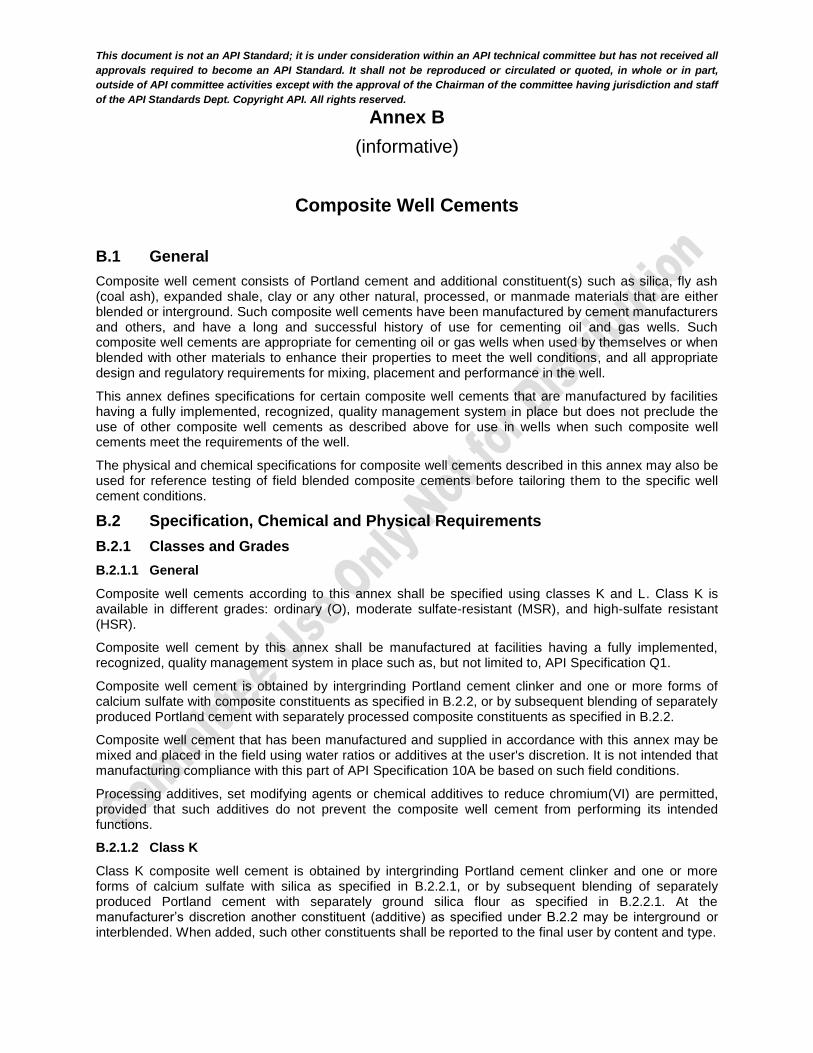
This document is not an API Standard; it is under consideration within an API technical committee but has not received all
approvals required to become an API Standard. It shall not be reproduced or circulated or quoted, in whole or in part,
outside of API committee activities except with the approval of the Chairman of the committee having jurisdiction and staff
of the API Standards Dept. Copyright API. All rights reserved.
Annex B
(informative)
Composite Well Cements
B.1 General
Composite well cement consists of Portland cement and additional constituent(s) such as silica, fly ash (coal ash), expanded shale, clay or any other natural, processed, or manmade materials that are either blended or interground. Such composite well cements have been manufactured by cement manufacturers and others, and have a long and successful history of use for cementing oil and gas wells. Such composite well cements are appropriate for cementing oil or gas wells when used by themselves or when blended with other materials to enhance their properties to meet the well conditions, and all appropriate design and regulatory requirements for mixing, placement and performance in the well.
This annex defines specifications for certain composite well cements that are manufactured by facilities having a fully implemented, recognized, quality management system in place but does not preclude the use of other composite well cements as described above for use in wells when such composite well cements meet the requirements of the well.
The physical and chemical specifications for composite well cements described in this annex may also be used for reference testing of field blended composite cements before tailoring them to the specific well cement conditions.
B.2 Specification, Chemical and Physical Requirements
B.2.1 Classes and Grades
B.2.1.1 General
Composite well cements according to this annex shall be specified using classes K and L. Class K is available in different grades: ordinary (O), moderate sulfate-resistant (MSR), and high-sulfate resistant (HSR).
Composite well cement by this annex shall be manufactured at facilities having a fully implemented, recognized, quality management system in place such as, but not limited to, API Specification Q1.
Composite well cement is obtained by intergrinding Portland cement clinker and one or more forms of calcium sulfate with composite constituents as specified in B.2.2, or by subsequent blending of separately produced Portland cement with separately processed composite constituents as specified in B.2.2.
Composite well cement that has been manufactured and supplied in accordance with this annex may be mixed and placed in the field using water ratios or additives at the user's discretion. It is not intended that manufacturing compliance with this part of API Specification 10A be based on such field conditions.
Processing additives, set modifying agents or chemical additives to reduce chromium(VI) are permitted, provided that such additives do not prevent the composite well cement from performing its intended functions.
B.2.1.2 Class K
Class K composite well cement is obtained by intergrinding Portland cement clinker and one or more forms of calcium sulfate with silica as specified in B.2.2.1, or by subsequent blending of separately produced Portland cement with separately ground silica flour as specified in B.2.2.1. At the manufacturer’s discretion another constituent (additive) as specified under B.2.2 may be interground or interblended. When added, such other constituents shall be reported to the final user by content and type.
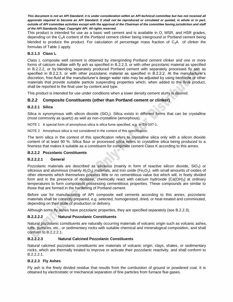
This document is not an API Standard; it is under consideration within an API technical committee but has not received all
approvals required to become an API Standard. It shall not be reproduced or circulated or quoted, in whole or in part,
outside of API committee activities except with the approval of the Chairman of the committee having jurisdiction and staff
of the API Standards Dept. Copyright API. All rights reserved.
This product is intended for use as a basic well cement and is available in O, MSR, and HSR grades, depending on the C3A content of the Portland cement clinker being interground or Portland cement being
blended to produce the product. For calculation of percentage mass fraction of C3A of clinker the
formulas of Table 1 apply.
B.2.1.3 Class L
Class L composite well cement is obtained by intergrinding Portland cement clinker and one or more forms of calcium sulfate with fly ash as specified in B.2.2.3, or with other pozzolanic material as specified in B.2.2.2, or by blending separately produced Portland cement with separately processed fly ash as specified in B.2.2.3, or with other pozzolanic material as specified in B.2.2.2. At the manufacturer’s discretion, free-fluid at the manufacturer’s design water ratio may be adjusted by using bentonite or other materials that provide suitable particle suspending properties which, when added to the final product, shall be reported to the final user by content and type.
This product is intended for use under conditions when a lower density cement slurry is desired.
B.2.2 Composite Constituents (other than Portland cement or clinker)
B.2.2.1 Silica
Silica is synonymous with silicon dioxide (SiO2). Silica exists in different forms that can be crystalline (most commonly as quartz) as well as non-crystalline (amorphous).
NOTE 1 A special form of amorphous silica is silica fume specified, e.g. in EN 197-1.
NOTE 2 Amorphous silica is not considered in the context of this specification.
The term silica in the context of this specification refers to crystalline silica only with a silicon dioxide content of at least 90 %. Silica flour or processed silica refers to crystalline silica being produced to a fineness that makes it suitable as a constituent for composite cement Class K according to this annex.
B.2.2.2 Pozzolanic Constituents
B.2.2.2.1 General
Pozzolanic materials are described as siliceous (mainly in form of reactive silicon dioxide, SiO2) or siliceous and aluminous (mainly Al2O3) materials, and iron oxide (Fe2O3), with small amounts of oxides of other elements which themselves possess little or no cementitious value but which will, in finely divided form and in the presence of moisture, chemically react with calcium hydroxide [Ca(OH)2] at ordinary temperatures to form compounds possessing cementitious properties. These compounds are similar to those that are formed in the hardening of Portland cement.
Before use for manufacturing of API composite well cements according to this annex, pozzolanic materials shall be correctly prepared, e.g. selected, homogenized, dried, or heat-treated and comminuted, depending on their state of production or delivery.
Although some fly ashes have pozzolanic properties, they are specified separately (see B.2.2.3).
B.2.2.2.2 Natural Pozzolanic Constituents
Natural pozzolanic constituents are naturally occurring materials of volcanic origin such as volcanic ashes, tuffs, pumices, etc., or sedimentary rocks with suitable chemical and mineralogical composition, and shall conform to B.2.2.2.1.
B.2.2.2.3 Natural Calcined Pozzolanic Constituents
Natural calcined pozzolanic constituents are materials of volcanic origin, clays, shales, or sedimentary rocks, which are thermally treated to improve or activate their pozzolanic reactivity, and shall conform to B.2.2.2.1.
B.2.2.3 Fly Ashes
Fly ash is the finely divided residue that results from the combustion of ground or powdered coal. It is obtained by electrostatic or mechanical separation of fine particles from furnace flue gases.
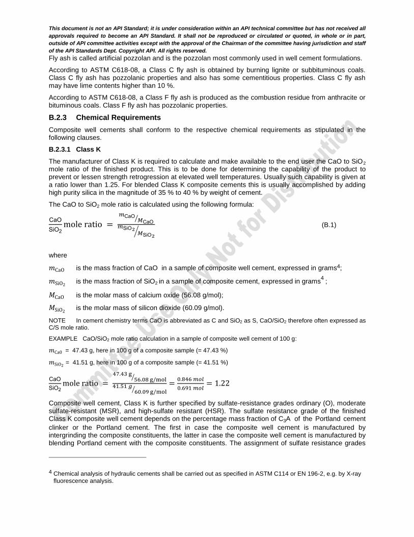
This document is not an API Standard; it is under consideration within an API technical committee but has not received all
approvals required to become an API Standard. It shall not be reproduced or circulated or quoted, in whole or in part,
outside of API committee activities except with the approval of the Chairman of the committee having jurisdiction and staff
of the API Standards Dept. Copyright API. All rights reserved.
Fly ash is called artificial pozzolan and is the pozzolan most commonly used in well cement formulations.
According to ASTM C618-08, a Class C fly ash is obtained by burning lignite or subbituminous coals. Class C fly ash has pozzolanic properties and also has some cementitious properties. Class C fly ash may have lime contents higher than 10 %.
According to ASTM C618-08, a Class F fly ash is produced as the combustion residue from anthracite or bituminous coals. Class F fly ash has pozzolanic properties.
B.2.3 Chemical Requirements
Composite well cements shall conform to the respective chemical requirements as stipulated in the following clauses.
B.2.3.1 Class K
The manufacturer of Class K is required to calculate and make available to the end user the CaO to SiO2 mole ratio of the finished product. This is to be done for determining the capability of the product to prevent or lessen strength retrogression at elevated well temperatures. Usually such capability is given at a ratio lower than 1.25. For blended Class K composite cements this is usually accomplished by adding high purity silica in the magnitude of 35 % to 40 % by weight of cement.
The CaO to SiO2 mole ratio is calculated using the following formula:
CaO
SiO2mole ratio =
𝑚CaO𝑀CaO
⁄
𝑚SiO2𝑀SiO2
⁄ (B.1)
where
𝑚CaO is the mass fraction of CaO in a sample of composite well cement, expressed in grams4;
𝑚SiO2 is the mass fraction of SiO2 in a sample of composite cement, expressed in grams
4 ;
𝑀CaO is the molar mass of calcium oxide (56.08 g/mol);
𝑀SiO2 is the molar mass of silicon dioxide (60.09 g/mol).
NOTE In cement chemistry terms CaO is abbreviated as C and SiO2 as S, CaO/SiO2 therefore often expressed as C/S mole ratio.
EXAMPLE CaO/SiO2 mole ratio calculation in a sample of composite well cement of 100 g:
𝑚Ca0 = 47.43 g, here in 100 g of a composite sample (= 47.43 %)
𝑚SiO2 = 41.51 g, here in 100 g of a composite sample (= 41.51 %)
CaO
SiO2mole ratio =
47.43 g56.08 g/mol⁄
41.51 𝑔60.09 g/mol⁄
=0.846 𝑚𝑜𝑙
0.691 𝑚𝑜𝑙= 1.22
Composite well cement, Class K is further specified by sulfate-resistance grades ordinary (O), moderate sulfate-resistant (MSR), and high-sulfate resistant (HSR). The sulfate resistance grade of the finished Class K composite well cement depends on the percentage mass fraction of C3A of the Portland cement
clinker or the Portland cement. The first in case the composite well cement is manufactured by intergrinding the composite constituents, the latter in case the composite well cement is manufactured by blending Portland cement with the composite constituents. The assignment of sulfate resistance grades
4 Chemical analysis of hydraulic cements shall be carried out as specified in ASTM C114 or EN 196-2, e.g. by X-ray
fluorescence analysis.

This document is not an API Standard; it is under consideration within an API technical committee but has not received all
approvals required to become an API Standard. It shall not be reproduced or circulated or quoted, in whole or in part,
outside of API committee activities except with the approval of the Chairman of the committee having jurisdiction and staff
of the API Standards Dept. Copyright API. All rights reserved.
of Class K to the C3A content of Class K clinker or cement, whatever production method is chosen is the
same as for Classes A to H. For calculation of percentage mass fraction of C3A of clinker and cement the
formulas of Section 5 , Table 1 apply.
NOTE Generally the formulas of Section 5, Table 1 apply only to the finished cement as an interground blend of Portland cement clinker and gypsum. When applying them to clinker only, the error due to the absence of gypsum can be considered as marginal (negligible) for the purpose of this annex.
B.2.3.2 Class L
The manufacturer of Class L shall calculate and make available to the end user the CaO to SiO2 mole ratio of the finished product.
No further chemical requirements are set for composite well cement, Class L.
B.2.4 Physical and Performance Requirements
Composite well cements shall conform to the respective physical and performance requirements specified in Table B.1 and in Section 8 to 11. When reporting results of specification testing the manufacturer shall always state them in conjunction with the applied mix water percentage at which these tests were performed.
The manufacturer of Class L shall additionally state the slurry density5 at the design mix water percentage and at which mix water percentage the performance tests were performed.
Users of composite well cement may mix at different mix water percentages and other modifying additives to meet the performance requirements of the well in which it is to be applied.
5 Slurry density preferred method of determination is described in API 10B-2.

This document is not an API Standard; it is under consideration within an API technical committee but has not received all
approvals required to become an API Standard. It shall not be reproduced or circulated or quoted, in whole or in part,
outside of API committee activities except with the approval of the Chairman of the committee having jurisdiction and staff
of the API Standards Dept. Copyright API. All rights reserved.
Table B.1—Physical and Performance Requirements for Composite Well Cements
Well Cement Class K
L
Mix water as per manufacturer’s requirements a a,b
Free-fluid content, maximum, percent (Clause 9) 5.9 5.9c
Compressive strength test
Curing time: 8 hr
Schedule number
Final curing temperature
°C (°F)
Curing pressure
Minimum compressive strength
MPa (psi)
(Section 10) NAd 60 (140) atmospheric 3.5
(500) NA
Compressive strength test
Curing time: 24 hr
Schedule number
(Table 8)
Final curing temperature
°C (°F)
Curing pressure
Minimum compressive strength
MPa (psi)
(Section 10) NA 38 (100) atmospheric NA 1.7
(250)
Thickening-time test
Specification Test schedule
number
Maximum Consistency
(15 to 30 minutes stirring period)
Bce
Thickening-time
(minimum/maximum)
minutes
(Section 11) 4 (Table 11) 30 NA 90/NA
(Section 11) 5 (Table 12) 30 70/140 NA
a The manufacturer shall indicate on certificates of conformance the design mix water percentage for the composite well
cement and at which performance tests are performed.
b Mix water percentage by slurry density desired. The manufacturer shall indicate on certificates of conformance the slurry
density at the design mix water percentage and at which performance tests are performed.
c Free- fluid may be adjusted by use of bentonite (see B.2.1.3) or other water adsorbing materials.
d NA indicates “not applicable.”
e Bearden units of consistency, Bc, obtained on a pressurized consistometer as defined in Section 11 and calibrated in
accordance with the same section.

This document is not an API Standard; it is under consideration within an API technical committee but has not received all
approvals required to become an API Standard. It shall not be reproduced or circulated or quoted, in whole or in part,
outside of API committee activities except with the approval of the Chairman of the committee having jurisdiction and staff
of the API Standards Dept. Copyright API. All rights reserved.
Annex C (normative)
Calibration and Verification of Well Cement Testing Equipment
C.1 Overview
This annex defines the requirements for calibration and verification of measurements by instruments used in testing cement for oil and gas well applications according to the procedures prescribed in this document. Henceforth, the term calibration is used to mean either verification and/ or calibration according to the requirements of this API Specification. Procedures will depend on the specific instrument used for the calibration. Manufacturer’s instructions should be followed for the calibration. Calibrations shall be conducted using instruments and devices traceable to national standards.
NOTE Calibration is a verification of an instrument or to actually make adjustments to the instrument if it is out of calibration. If a verification shows the instrument to be in calibration, the date and verification data will be the calibration. In this calibration section, the word “verification” pertains to instruments that cannot be changed if they are inaccurate and the word “calibrate” pertains to instruments that if they are out of calibration as seen by the “verification” of the instrument may be adjusted to get them into calibration.
C.2 General
The following sections prescribe the requirements for interval and accuracy of calibration of devices used in a laboratory conducting tests according to this API Standard. Table C.1 lists the requirements by equipment type and Table C.2 lists the frequency and allowable tolerances.
Volumetric glassware (graduated cylinders, conical flask, and similar equipment) calibration is generally performed by the glassware supplier and may be part of the purchase specification. Glassware users should obtain documented evidence, where deemed important, of glassware calibration from the supplier. Calibration may be checked gravimetrically before the first use. Periodic recalibration is not required. A procedure for graduated cylinders applicable to any volumetric glassware is given in C.3.15.
Dimensions of apparatuses such as cube molds and consistometers cells may be verified using a caliper accurate to at least 0.1 mm ( 0.005 in.).

This document is not an API Standard; it is under consideration within an API technical committee but has not received all
approvals required to become an API Standard. It shall not be reproduced or circulated or quoted, in whole or in part,
outside of API committee activities except with the approval of the Chairman of the committee having jurisdiction and staff
of the API Standards Dept. Copyright API. All rights reserved.
Table C.5—Equipment Calibration Requirements
Measurement Instrument
Ba
lan
ce
Mix
ing
De
vic
e
HP
HT
Co
ns
isto
me
ter
Atm
os
ph
eri
c
Co
ns
isto
me
ter
Ha
nd
he
ld T
ime
rs
Ha
nd
he
ld
Th
erm
om
ete
rs
Wa
ter
an
d C
uri
ng
Ba
ths
Cu
be
mo
lds
Lo
ad
Fra
me
Pre
ss
ure
d D
en
sit
y
Ba
lan
ce
We
igh
t S
ets
Ch
art
Re
co
rde
r (
wh
ere
Used
)
Mass V/C V V
Timer V V V V V/C (speed)
Rotation V V/C V/C
Temperature V/C V/C V/C V/C V/C
Dimensions V V
Consistency V/C V/C
Pressure gauge V/C V/C V/C
Auxiliary display V V
Indication V/C V/C
NOTE V/C indicates the verification of calibration needs to be performed first. If the verification values are acceptable at the time it is verified, the verification will serve as a calibration. If it is not in calibration tolerance, the calibration needs to be peformed.
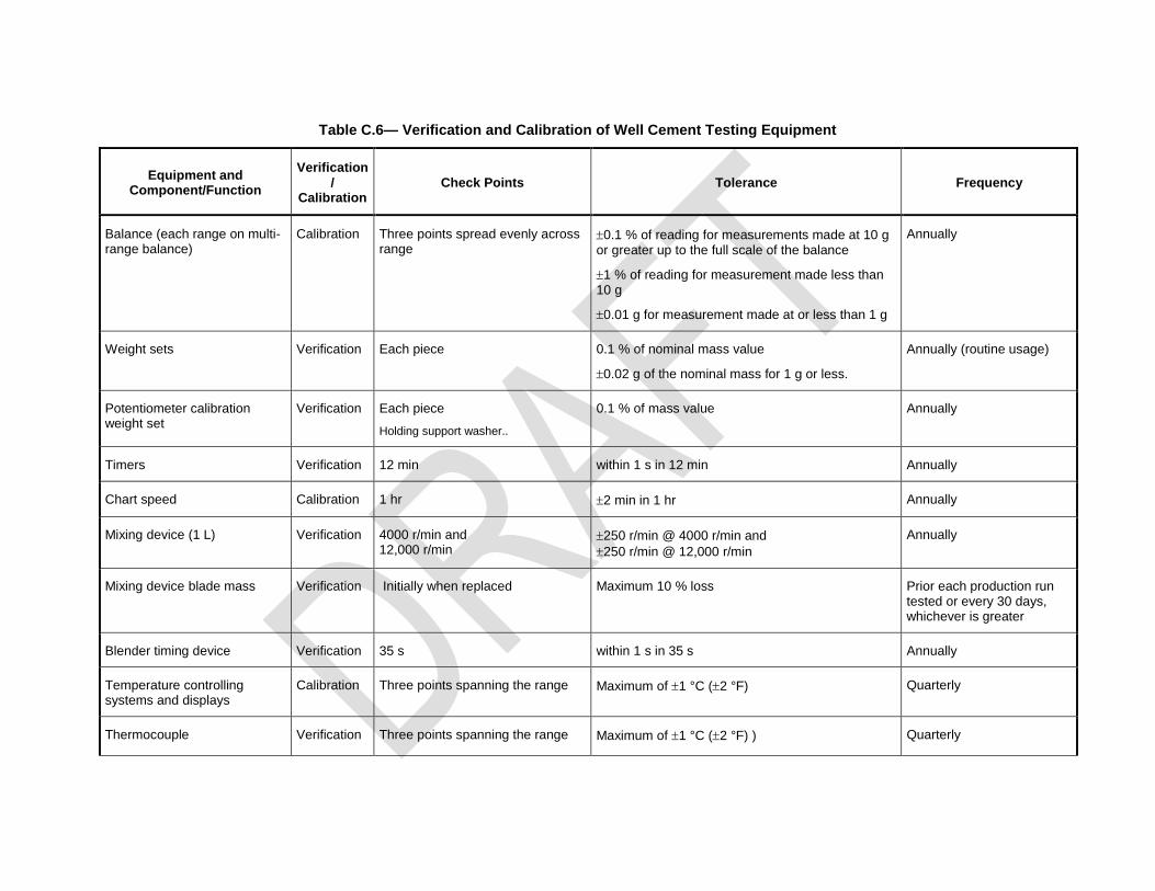
Table C.6— Verification and Calibration of Well Cement Testing Equipment
Equipment and Component/Function
Verification /
Calibration Check Points Tolerance Frequency
Balance (each range on multi-range balance)
Calibration Three points spread evenly across range
0.1 % of reading for measurements made at 10 g or greater up to the full scale of the balance
1 % of reading for measurement made less than 10 g
0.01 g for measurement made at or less than 1 g
Annually
Weight sets Verification Each piece 0.1 % of nominal mass value
0.02 g of the nominal mass for 1 g or less.
Annually (routine usage)
Potentiometer calibration weight set
Verification Each piece
Holding support washer..
0.1 % of mass value Annually
Timers Verification 12 min within 1 s in 12 min Annually
Chart speed Calibration 1 hr 2 min in 1 hr Annually
Mixing device (1 L) Verification 4000 r/min and 12,000 r/min
250 r/min @ 4000 r/min and
250 r/min @ 12,000 r/min
Annually
Mixing device blade mass Verification Initially when replaced Maximum 10 % loss Prior each production run tested or every 30 days, whichever is greater
Blender timing device Verification 35 s within 1 s in 35 s Annually
Temperature controlling systems and displays
Calibration Three points spanning the range Maximum of 1 °C (2 °F) Quarterly
Thermocouple Verification Three points spanning the range Maximum of 1 °C (2 °F) ) Quarterly
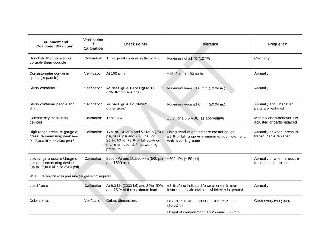
Equipment and Component/Function
Verification /
Calibration Check Points Tolerance Frequency
Handheld thermometer or portable thermocouple
Calibration Three points spanning the range Maximum of 1 °C (2 °F) Quarterly
Consistometer container speed (or paddle)
Verification At 150 r/min 15 r/min at 150 r/min Annually
Slurry container Verification As per Figure 10 or Figure 11 ( “INSP” dimensions)
Maximum wear 1.0 mm (0.04 in.) Annually
Slurry container paddle and shaft
Verification As per Figure 12 (“INSP” dimensions)
Maximum wear 1.0 mm (0.04 in.) Annually and whenever parts are replaced
Consistency measuring devices
Calibration Table D.4 5 Bc or 0.5 VDC, as appropriate Monthly and whenever it is adjusted or parts replaced
High range pressure gauge or pressure measuring device—
(>17,000 kPa or 2500 psi) a
Calibration 17MPa, 34 MPa and 52 MPa (2500 psi, 5000 psi and 7500 psi) or 25 %, 50 %, 75 % of full scale or maximum user defined working pressure
Using deadweight tester or master gauge;
1 % of full range or minimum gauge increment, whichever is greater
Annually or when pressure transducer is replaced
Low range pressure Gauge or pressure measuring device— (up to 17,000 kPa or 2500 psi)
Calibration 3500 kPa and 10,500 kPa (500 psi and 1500 psi)
300 kPa ( 50 psi) Annually or when pressure transducer is replaced
NOTE Calibration of air pressure gauges is not required
Load frame Calibration At 9.0 kN (2000 lbf) and 25%, 50% and 75 % of the maximum load
±2 % of the indicated force or one minimum instrument scale division, whichever is greated
Annually
Cube molds Verification Cubes dimensions Distance between opposite side: 0.5 mm
(0.02in.)
Height of compartment: +0.25 mm/-0.38 mm
Once every two years

Equipment and Component/Function
Verification /
Calibration Check Points Tolerance Frequency
(+0.01in./-0.015 in.)
Pressurized density balance—Indicated density
Calibration Water at 1800 kg/m3 to 2300 kg/m
3
(15 lbm/gal to 19 lbm/gal) 10 kg/m
3 (0.1 lbm/gal) from actual Annually
Data acquisition devices Verification Same as T and P Adjust or prepare calibration table With sensor recorded
Volumetric glasswareb, NRd Before first use
Graduated cylinderb, Verification /Calibration
5 points If required prepare calibration table Before first use
Sievesc NR
a Check points at 17MPa, 34 MPa and 52 MPa (2500 psi, 5000 psi and 7500 psi) are the minimum requirements for high range pressure gauges or measuring pressure device used for test conditions as per 10A Specification
b Volumetric glassware including graduated cylinders calibration is done by supplier. and may be part of the purchase specification. Calibration may be checked gravimetrically before the
first use. Periodic recalibration is not required.
b Supplier's verification that a sieve conforms to ASTM E11 is satisfactory evidence of compliance. No periodic calibration of sieves is required.
c Not required
This document is not an API Standard; it is under consideration within an API technical committee but has not received all
approvals required to become an API Standard. It shall not be reproduced or circulated or quoted, in whole or in part,
outside of API committee activities except with the approval of the Chairman of the committee having jurisdiction and staff
of the API Standards Dept. Copyright API. All rights reserved.
The individual performing the verification/calibration shall possess adequate skill and training to properly perform the calibration according to the procedures specified for the device(s) being used.
Records of such calibration shall be maintained in a manner that the data or record cannot be altered after certification. The records shall be maintained at least as long as the data from tests performed during the calibration period on the specific instrument are maintained.
Veridfication and calibration records shall contain, as appropriate:
model name/number, serial number, and local identification number of the instrument;
name, model number, and serial number of instrument used for the calibration;
certification number, date of certification, and date next calibration against national standard is due for the calibration instrument;
calibration inputs from the calibration instrument and the initial (before calibration) and final (calibrated) indications from instrument being calibrated;
indication that instrument passed or failed each calibration point;
condition found/condition left (e.g. out of or in calibration);
adjustments made and results after adjustment;
date of calibration;
name and signature of calibration technician;
if calibration is by technician from an outside service, name of service, location, and phone number.
Some instruments have multiple cells or testing systems within one unit (e.g. dual-cell consistometers). In such cases, each cell or testing system shall be verified and/or calibrated ( if not in calibration) individually with a separate certificate showing a unique identifier for each testing system. Components that are common to all of the cells or testing systems need be calibrated only once, but the calibration data shall be indicated on each certificate.
When the device is being used for a test and a verification or calibration becomes due, the verification or calibration remains valid for the duration of that test and the instrument should be calibrated at the end of that test.
C.3 Requirements
C.3.1 Balances
Balances shall be verified and/or calibrated (if not in calibration) no less frequently than annually.
Balances shall be accurate to 0.1 % of reading for measurements made at 10 gram or greater up to the
full scale of the balance. Balances shall be accurate to 1 % of reading for measurement made less than
10 gram. For measurements of 1 gram or less, balances should be calibrated at 0.01 gram. Balances shall have two (2) decimal place precision at a minimum. Each range of a dual range balance shall be calibrated in this fashion.
C.3.2 Weight Sets
Weight sets should be verified against reference weights traceable to a national standard. Weight sets to be verified include, but are not limited to, those used daily (routine weighing), and to calibrate consistometer potentiometers (dedicated potentiometer calibration weight set) or their equivalent. Weight sets should be verified and/or calibrated no less frequently than once annually. Weights should conform
within 0.1 % of the nominal weight excepted for weights with a mass equal or less than 10 g (Table C.3).
For weights of 10 g and less should conform within 0.02 g of the nominal mass. If weights are not conform to the specification they should be discarded or sent to the manufacturer for recertification.
NOTE Annual verification should be required for weight sets use daily for routine weighing. For reference weight sets use for annual verification, weights should be recertified against certified master weights every 5 years providing weights sets are kept in a padded dust and moisture proof holder and used with tongs with plastic tips, If not the case, reference weight sets should be recertified every 2 years.

This document is not an API Standard; it is under consideration within an API technical committee but has not received all
approvals required to become an API Standard. It shall not be reproduced or circulated or quoted, in whole or in part,
outside of API committee activities except with the approval of the Chairman of the committee having jurisdiction and staff
of the API Standards Dept. Copyright API. All rights reserved.
Table C.3—Permissible Variation in Mass of Reference Weights
Mass
g
Permissible variation
g
1000 ±1.00
500 ±0.50
300 ±0.30
200 ±0.20
100 ±0.10
50 ±0.05
≤10 ±0.02
C.3.2 Mixing Device (blender)
C.3.2.1 Mixing Device Speed
Mixing device display of rotational speed shall be verified and/or calibrated (if not in calibration) no less frequently than annually. The tolerance measured by a calibrated tachometer shall not deviate more than the limits in Table C.2
However when mixing a cement slurry, the one one liter blender shall operate at a low speed range of
3750 r/min to 4250 r/min (4000 r/min 250 r/min) and high speed range of 11,750 r/min to 12,250 r/min
(12,000 r/min 250 r/min). The indicated speed shall not deviate by more than 250 r/min at either the low speed or the high speed from the true speed observed using a calibrated tachometer.
NOTE The ability of the controller to maintain speeds within the required range during mixing a cement slurry is not a calibration issue. If the mixing devicer is unable to control within the required range, the blender motor or controller shall be repaired or replaced, as appropriate. Typical motors available for the 1 L (1 quart) mixer are 3.6 A/0.04HP and the 7 A/0.7 HP; typically the 3.6 A motor will not maintain the tolerance especially with viscous slurry.
C.3.2.2 Blender Blade
Initial blade weight and dimensions may vary due to the manufacturing process. The weight loss of the blender blade (blade only, not the blade assembly) shall be verified to be no more than 10 % when it is changed. The mixing blade shall be weighed initially and prior to each production run tested or every 30 days, whichever is greater. Replace with an unused blade if critical blade deformation has occurred or prior to a 10 % mass loss.
Users will develop procedures to ensure that the blade is not used with >10 % weight loss compared to its unused (out of the package) weight and will develop a system to confirm weight loss of the blade when it is changed. This system will include a method of identifying the blender container in which the blade is installed. A log of blade weights and dates changed will be maintained with the calibration records. A practical method of judging when a blade is approaching the limit in weight loss is by comparing the blade in the blender to a blade with known weight loss (such as is shown in the photos in Figure C.1). The appearance of wear for a hardened blade may be different than shown in Figure C.1 for a no-hardened blade.
C.3.2.3 Blender Timing Controller
Blender timing controller device shall be verified against a calibrated timer (stopwatch) for high speed mixing ( 12,000 rpm) time at 35 s ±1 s.

This document is not an API Standard; it is under consideration within an API technical committee but has not received all
approvals required to become an API Standard. It shall not be reproduced or circulated or quoted, in whole or in part,
outside of API committee activities except with the approval of the Chairman of the committee having jurisdiction and staff
of the API Standards Dept. Copyright API. All rights reserved.
Figure C.1—Worn Blade (right) Compared to a New One (left)
C.3.3 Timers
Timers on all instruments shall be verified/and or calibrated (if not in calibration) no less frequently than annually. This includes timers on consistometers, handheld timers and any other timer, whether as part of an instrument or separate. Timers shall be accurate within ±5 seconds per hour and shall be verified over a period of no less than 12 minutes. Calibration may use the time signal from the NIST or similar web sites and radio stations. If not within required accuracy, the units shall be adjusted or replaced.
C.3.4 Recorders
Charts used for recording thickening times or other data shall be checked at least annually to ensure they vary by no more than 2 min/hr. This can be done by running the chart, causing a deflection of the temperature or pressure trace at the beginning and end of one hour according to a calibrated timer, and measuring the deviation on the chart. The chart on which this recording is made shall be maintained with the calibration record for the instrument.
C.3.5 Temperature Devices
C.3.5.1 Temperature measuring and controlling devices shall be verified and/or calibrated (if not in calibration) no less frequently than quarterly. This includes thermometers, thermocouples, and temperature controllers on consistometers, curing chambers, and those that are used separate from or are not an integral part of the instrument. Measurements shall be made at no less than three temperatures spanning the manufacturer or user defined operating range of the equipment on or with which the device is used. The lowest temperature calibrated shall be no more than 5 °C (10 °F) above the minimum and the highest temperature calibrated shall be no more than 5 °C (10 °F) below the maximum of the user-defined operating range of the instrument.
C.3.5.2 Thermometers or thermocouples shall be verified for accuracy by use of a known temperature source (such as a heat block) with a thermometer or thermocouple that is certified and traceable to a national standardization body. Accuracy shall be within 1 °C (2 °F) or for special J type thermocouple accuracy shall be 0.04 % of the temperature indication. If the thermometer or thermocouple error is greater than that, it shall be replaced by one meeting the accuracy requirements. Thermocouples mounted in the cylinder wall of a consistometer are exempt from calibration, but during the test,
This document is not an API Standard; it is under consideration within an API technical committee but has not received all
approvals required to become an API Standard. It shall not be reproduced or circulated or quoted, in whole or in part,
outside of API committee activities except with the approval of the Chairman of the committee having jurisdiction and staff
of the API Standards Dept. Copyright API. All rights reserved.
adjustments should be made to the controlling temperature when control is from the oil thermocouple so the final temperature of the slurry is within the required test temperature.
C.3.5.3 Temperature controlling systems consist of:
the sensing device (normally a thermocouple);
display (may be integral to controller or may be separate);
the controller that receives input from the sensing device and in turn provides output to the heating or cooling medium. The output circuit is not calibrated in this procedure; and
all wiring, connectors, etc. between the sensor and the controller.
The temperature controller may be verified and /or calibrated while connected to its thermocouple placed in a calibrated heat source or using a cold-junction compensated input device in place of the thermocouple. If the controller is calibrated using a cold-junction compensated input device, the thermocouple shall be calibrated independently. The thermometer or thermocouple that is used for the verification of calibration tolerance shall be certified and traceable to a national standardization body. The controller accuracy shall be within 1 °C (2 °F). If the system is not within the required accuracy, the source of the inaccuracy should be determined and the component(s) that is (are) not within the required accuracy shall be adjusted or replaced.
The temperature controller shall be verified for accuracy at an interval no less than quarterly and be checked at no less than three temperatures spanning the operating range of the equipment on or with which the device is used. The lowest temperature calibrated shall be no more than 5 °C (10 °F) above the minimum and the highest temperature calibrated shall be no more than 5 °C (10 °F) below the maximum of the user-defined operating range of the instrument.
Temperature displays that are separate from the controller shall be calibrated by the same methods used to calibrate the controller. Separate displays shall have their own calibration record.
C.3.5.4 See C.3.14 for temperature data acquisition.
C.3.5.5 Guidance for Temperature Device Calibration
This subsection provides additional guidance for temperature device calibration.
C.3.5.5.1 Heating medium
The heating medium shall permit proper immersion of both the test thermocouple (the one being verified/calibrated) and the reference thermocouple or reference thermometer. The medium may be a fluidized solids bath, a heated block, or a furnace. The equipment shall be capable of maintaining a stable temperature that is uniform throughout the test section. If the heat source (heater and instrument) is portable, it should be allowed to stabilize at the ambient temperature prior to being used. This is especially true when the instrument is removed from a car or storage room, etc.
C.3.5.5.2 Procedure
Items listed here are those needing special attention or related to the use of the indicated type of equipment.
The test and reference thermocouple or thermometer shall be placed as close together in the heating medium as possible.
After each change of the temperature setting, the temperature of the heating medium shall be allowed to stabilize before reading the reference temperature (or voltage) and the test thermocouple temperature (or voltage). If several thermocouples are checked in sequence, each one shall be allowed to reach a stable reading before making the calibration measurement.
If the test thermocouple does not accurately sense the temperature, a calibration curve shall be drawn and used to correct the indicated temperatures from the test thermocouple. Occasionally, small inaccuracies in thermocouple response can be compensated for during the calibration of the temperature-measuring system being used in conjunction with the thermocouple (D.3.5.3).
This document is not an API Standard; it is under consideration within an API technical committee but has not received all
approvals required to become an API Standard. It shall not be reproduced or circulated or quoted, in whole or in part,
outside of API committee activities except with the approval of the Chairman of the committee having jurisdiction and staff
of the API Standards Dept. Copyright API. All rights reserved.
C.3.5.5.3 Verification and calibration of temperature-measuring systems and controllers
C.3.5.5.3.1 Equipment
The verification/calibration of temperature-measuring systems and controllers requires a millivolt source, the correct connecting thermocouple extension cable for the type thermocouple being used, and possibly a thermometer and a table of reference voltages. Signal sources, or calibrators, are of two types, namely, uncompensated and cold-junction compensated. Several commercial calibrators are available that are cold-junction compensated and have a digital display of the temperature equivalent of the millivolt signal being supplied. The accuracy of all calibration equipment shall be traceable to national standards certification. Some older galvanometer type temperature-indicating instruments and controllers require a stronger signal for operation than the newer potentiometric and digital type temperature-measuring systems and controllers, and thus require a calibrator with sufficient signal strength to give an accurate calibration.
An alternate method consists of placing the thermocouple that is connected to the controlling or indicating instrument into a heat source and comparing it with a calibrated thermocouple or thermometer. The temperature of the heat source is then changed as in D.3.5.5.2 to certify the controlling or indicating instrument is accurately calibrated.
C.3.5.5.3.2 Procedure
Follow the manufacturer’s procedure for calibrating temperature-measuring systems and controllers. For greatest accuracy, allow proper warm-up time for calibrators, temperature-measuring systems, and controllers as specified by the manufacturer. The following items need special attention.
Fit the thermocouple extension cable with a proper thermocouple-grade adapter to permit plugging it into the same receptacle used for connecting the test equipment thermocouple. Take care to ensure the correct polarity of the connections.
Thermocouple calibrators with cold-junction compensation need only be properly connected with the proper thermocouple extension cable and thermocouple connectors. The temperature-measuring systems and/or controllers using this signal shall display the same temperature within the accuracy of the thermometer or controllers as supplied by the manufacturer.
Uncompensated thermocouple calibrators require a thermometer to determine the cold-junction temperature of the thermocouple extension cable connection of the calibrator. This cold-junction temperature shall be set on the calibrator by the operator.
The use of an uncompensated millivolt potentiometer requires that the temperature at the calibrator/thermocouple extension cable terminals be read with a thermometer of known accuracy. The millivolt equivalent of this temperature is then subtracted from the equivalent test millivolt signal to obtain the calibrator millivolt signal used. These voltages may be found in reference millivolt/temperature tables for the type of thermocouple in use.
The temperature of the calibration instrument should be allowed to stabilize at the ambient temperature at the location where it is being used. This is especially true when the instrument is removed from a car or a storage room, etc.
C.3.5.5.4 Specific procedure for atmospheric consistometer
When verifying the temperature calibration of an atmospheric consitometer, place one slurry container in the unit and leave the second one out. Place the reference thermocouple (attached to a master temperature calibration instrument) in the open hole as close as possible to the atmospheric consistometer thermocouple and heat the consistometer to no less than three temperatures from ambient temperature to 88 °C (190°C) to verify the accuracy of the temperature indication. Calibrate the controller if it is not in calibration. If it is in calibration, use the verification as the calibration and date it for reference.
C.3.5.5.5 Specific procedure for atmospheric pressure water bath
When verifying the temperature calibration of an atmospheric pressure water bath place a stirring device in the bath ( if it does not have one) along with a reference thermocouple attached to a master temperature calibration instrument in the water bath. Heat the water bath to no less than Three temperatures from ambient temperature to 88 °C (190°C) to verify the accuracy of the temperature
This document is not an API Standard; it is under consideration within an API technical committee but has not received all
approvals required to become an API Standard. It shall not be reproduced or circulated or quoted, in whole or in part,
outside of API committee activities except with the approval of the Chairman of the committee having jurisdiction and staff
of the API Standards Dept. Copyright API. All rights reserved.
indication. Calibrate the controller if it is not in calibration. If it is in calibration, use the verification as the calibration and date it for reference
C.3.6 Instrument Rotation
Rotation of consistometer containers (or paddles) at 150 r/min shall be verified and/or calibrated (if not in calibration) no less frequently than quarterly. The tolerance measured by a calibrated tachometer shall not deviate more than 15 r/min.
C.3.7 Pressurized Consistometer Slurry Container Assembly
Pressurized slurry container, paddle and paddle shaft key dimensions (dimensions tagged as “INSP”, Figures 10 to 12 ) shall be verified to judge wear, maximum acceptable wear is 1 mm ( 0.04in.). Dimensions shall be verified no less frequently than annually or whenever a paddle or a paddle shaft is replaced. If dimensions are found outside tolerances the slurry container part needs to be discarded.
To verify dimensions a caliper accurate to 0.05 mm (0.002 in.) at minimum is required.
C.3.8 Consistency Measurement Device or Potentiometer
C.3.8.1 General
The potentiometer or other consistency-measuring device shall be verified and/or calibrated if not in calibration) no less frequently than monthly. A new calibration is required whenever repairs or adjustments are made to the device (such as calibration spring, resistor, contact arm). Accuracy shall be
maintained within 5 Bc (if output is in Bc) or 0.5 volt (if output is in volts) across the calibration range.
When the calibration is of a system (potentiometer, wiring, voltmeter, etc.), for the calibration to be valid the potentiometer must be kept together with the consistometer with which it has been calibrated. For these systems, laboratories should devise a method of identifying the potentiometer with the consistometer on which it is calibrated and ensure it is only used on that consistometer.
Some potentiometer calibration devices allow the potentiometer to be calibrated so that the voltage output is fixed based on applied load (equivalent to Bc). In such a case, provided all potentiometers are adjusted
to the same voltage output vs load [or consistency (Bc)], the potentiometers may be interchanged
between machines.
C.3.8.2 Procedure
A calibration chart or table showing indicated consistency vs input consistency (mass) shall be maintained. The entire range of consistencies shall be checked as indicated in Table C.4. Consistency values shall be reported based on the calibration curve or table.
A weight-loaded device (see Figure C.2 for a typical potentiometer calibrating device and Figure 13 for a typical potentiometer) is used to produce a series of torque-equivalent values for consistency, defined by:
( )c78.2 + 20.02T B (B.1)
where
T is torque, expressed in gram•centimeters (g•cm);
Bc is consistency expressed in Bearden units.
Specific potentiometer calibration weights are used to apply torque to the potentiometer spring, using the radius of the potentiometer frame as a lever arm. Weights cause a deflection and the resulting DC voltage is recorded and used to determine Bc (alternatively, some instruments display the Bc equivalent directly).
Slurry consistencies at ±5 Bc versus equivalent torques (mass of calibration weights at ±0.1 g) for
potentiometer with a radius of 52 mm ±1mm are provided Table C.4. Operating instructions from the manufacturer should be followed for proper calibration.

This document is not an API Standard; it is under consideration within an API technical committee but has not received all
approvals required to become an API Standard. It shall not be reproduced or circulated or quoted, in whole or in part,
outside of API committee activities except with the approval of the Chairman of the committee having jurisdiction and staff
of the API Standards Dept. Copyright API. All rights reserved.
Figure C.2—Common Calibrating Device for Pressurized Consistometer Potentiometer
Table C.4—Slurry Consistency vs Equivalent Torque
(for Potentiometer with Radius of 52 mm ±1 mm)
Torque Equivalent
(g•cm)
Mass of Added Calibration
Weightsa
±0.1% of the indicated mass
Slurry Consistency
(Bc 5)
260 50 9
520 100 22
780 150 35
1040 200 48
1300 250 61
1560 300 74
1820 350 87
2080 400 100
NOTE 1 For a potentiometer with a radius other than (52 1) mm, an adaptor ring with a radius of (52 1) mm or an appropriate table of equivalent tolerances is required.
NOTE 2 A consistency reading of a potentiometer may vary no more than 5 Bc from the slurry consistency shown in this
table.
a Mass of added calibration weight includes mass of the holding support washer..
C.3.9 Pressure Gauges and Pressure-measuring Devices
C.3.9.1 Pressure gauges shall be verified and/or calibrated (if not in calibration) no less frequently than annually using a deadweight tester or a master gauge. The term gauge includes pressure-sensing transducers.

This document is not an API Standard; it is under consideration within an API technical committee but has not received all
approvals required to become an API Standard. It shall not be reproduced or circulated or quoted, in whole or in part,
outside of API committee activities except with the approval of the Chairman of the committee having jurisdiction and staff
of the API Standards Dept. Copyright API. All rights reserved.
C.3.9.2 Gauges designed to measure pressures greater than 17,000 kPa (2500 psi) shall be calibrated at a minimum of 25 %, 50 %, and 75 % of full scale or the maximum user defined working pressure of the
equipment on or with which it is used. Maximum allowable error is 1 % of full range or one minimum gauge increment, whichever is greater.
NOTE High range gauges used for Specification 10 A testing shall be calibrated at 17MPa, 34 MPa and 52 MPa (2500 psi, 5000 psi and 7500 psi) with a maximum defined working pressure of the equipment of 69 MPa (10,000 psi).
C.3.9.3 Gauges designed to measure pressures up to 17,000 kPa (2500 psi) shall be calibrated with
allowable error of 300 kPa ( 50 psi) at a minimum gauge reading of 3500 kPa ( 500 psi) and at a
gauge reading of 10,500 kPa ( 1500 psi) or the maximum allowable working pressure of the equipment on or with which it is used.
C.3.8.4 Calibration of gauges showing pressure of air used to operate pumps and purge pressure vessels of liquid is not required.
C.3.10 Load Frame
The load frame used to measure break force of cement specimens shall be verified/ and or calibrated ( if
not in calibration) no less frequently than annually. Indicated force shall deviate by no more than 2 % of the applied load or one minimum instrument scale division, whichever is greater, at 9.0 kN (2000 lbf) load and at a minimum of 25 %, 50 %, and 75 % of the range of the load cell or load indicator. With units having multiple indicators for different ranges, each indicator shall be calibrated according to these criteria.
D.3.11 Cubes molds
Cubes molds used to prepared cement specimens shall be verified no less frequently than two years.
Cube dimensions to verified and tolerances are provided Table C.5. If molds are out of tolerances, molds should be discarded.
Table C.5 — Dimensions for 50-mm (2-in.) Cube Molds
Specification Molds
Distance between
opposite side
50.0 mm ±0.5 mm
(2.00 in. ±0.02 in.)
Height of compartments 50.0 mm +0.25mm/-0.38 mm
(2.0 n. +0.01 in./-0.015 in.)
C.3.12 Data Acquisition
C.3.12.1 Data acquisition can be by chart recorder or by electronic recording, such as computer data acquisition, or both.
D.3.12.2 For devices with chart recorders, the indication of temperature and pressure should be recorded during the calibration. If the chart can be adjusted to correct indication, the record on the chart should show the indication of a verification check before calibration and after adjustment of the chart. For those without an adjustment, a calibration table should be maintained with the instrument and appropriate corrections made to charts of all tests conducted with the instrument. The chart should be attached to the calibration record. The use of chart recorders is discouraged due to their inaccuracy.
D.3.12.3 Electronic data recording should be verified by acquiring data during the calibration of the system and checking the accuracy of the data recorded. If the acquisition deviates by more than the limits for temperature (C.3.5) and pressure (C.3.9), corrections should be made. For dedicated data acquisition systems, the data acquisition system should conform to the limits prescribed above for the data they are designed to record.
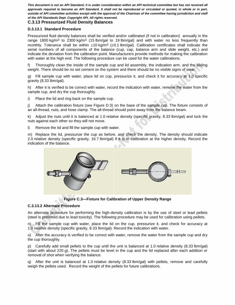
This document is not an API Standard; it is under consideration within an API technical committee but has not received all
approvals required to become an API Standard. It shall not be reproduced or circulated or quoted, in whole or in part,
outside of API committee activities except with the approval of the Chairman of the committee having jurisdiction and staff
of the API Standards Dept. Copyright API. All rights reserved.
C.3.13 Pressurized Fluid Density Balances
D.3.13.1 Standard Procedure
Pressurized fluid density balances shall be verified and/or calibrated (if not in calibration) annually in the range 1800 kg/m3 to 2300 kg/m3 (15 lbm/gal to 19 lbm/gal) and with water no less frequently than
monthly. Tolerance shall be within 10 kg/m3 (0.1 lbm/gal). Calibration certificates shall indicate the serial numbers of all components of the balance (cup, cap, balance arm and slide weight, etc.) and indicate the deviation from the calibration point. Manufacturers provide methods for making the calibration with water at the high end. The following procedure can be used for the water calibrations.
f) Thoroughly clean the inside of the sample cup and lid assembly, the indication arm, and the sliding weight. There should be no set cement on the system and there should be no visible signs of wear.
g) Fill sample cup with water, place lid on cup, pressurize it, and check it for accuracy at 1.0 specific gravity (8.33 lbm/gal).
h) After it is verified to be correct with water, record the indication with water, remove the water from the sample cup, and dry the cup thoroughly.
i) Place the lid and ring back on the sample cup.
j) Attach the calibration fixture (see Figure D.3) on the base of the sample cup. The fixture consists of an all-thread, nuts, and hose clamp. The all-thread should point away from the balance beam.
k) Adjust the nuts until it is balanced at 1.0 relative density (specific gravity, 8.33 lbm/gal) and lock the nuts against each other so they will not move.
l) Remove the lid and fill the sample cup with water.
m) Replace the lid, pressurize the cup as before, and check the density. The density should indicate 2.0 relative density (specific gravity, 16.7 lbm/gal) if it is in calibration at the higher density. Record the indication of the balance.
Figure C.3—Fixture for Calibration of Upper Density Range
C.3.13.2 Alternate Procedure
An alternate procedure for performing the high-density calibration is by the use of steel or lead pellets (steel is preferred due to lead toxicity). The following procedure may be used for calibration using pellets.
n) Fill the sample cup with water, place the lid on the cup, pressurize it, and check for accuracy at 1.0 relative density (specific gravity, 8.33 lbm/gal). Record the indication with water.
o) After the accuracy is verified to be correct with water, remove the water from the sample cup and dry the cup thoroughly.
p) Carefully add small pellets to the cup until the unit is balanced at 1.0 relative density (8.33 lbm/gal) (start with about 220 g). The pellets must be level in the cup and the lid replaced after each addition or removal of shot when verifying the balance.
q) After the unit is balanced at 1.0 relative density (8.33 lbm/gal) with pellets, remove and carefully weigh the pellets used. Record the weight of the pellets for future calibrations.
This document is not an API Standard; it is under consideration within an API technical committee but has not received all
approvals required to become an API Standard. It shall not be reproduced or circulated or quoted, in whole or in part,
outside of API committee activities except with the approval of the Chairman of the committee having jurisdiction and staff
of the API Standards Dept. Copyright API. All rights reserved.
r) Weigh out twice the amount of pellets recorded in Step d), place the pellets in the cup, and level them. Replace the lid and check the reading of the density. The indicated density should be 2.0 relative density (specific gravity, 16.7 lbm/gal). Record the indication and the weight of these pellets.
Step c) can be eliminated from future verifications/calibrations, if the pellets used in Steps d) and e) are saved in clean sealed containers or if the pellets are weighed out each time according to the recorded values in Steps d) and e). In all cases, it is important that the pellets be level in the cup before each verification.
C.3.14 Volumetric Glassware
C.3.14.1 General
Calibration of pipettes, graduated cylinders, conical flask and similar equipment is generally performed by the glassware supplier and may be part of the purchase specification. Glassware users should obtain documented evidence, where deemed important, of glassware calibration from the supplier. Calibration may be checked gravimetrically before the first use. Periodic recalibration is not required. A procedure for calibration of graduated cylinders herafter.
C.3.14.2 Procedure—Verification/Calibration of Graduated Cylinders
The following procedure shall be followed to verified calibration of graduated cylinders . These procedure may be adapted to any volumetric glassware.
a) Allow the receiver and deionized (or distilled) water to reach ambient temperature. Record the temperature to the nearest 0.5 °C (1 °F).
b) Place the clean, empty receiver, with its base, on the balance and tare to zero.
c) Fill the receiver with deionized (or distilled) water, while it is on the balance, to the various graduation marks in increments of 2 ml for the 10 ml receiver, in increments of 4 ml for the 20 ml receiver, and in increments of 10 ml for the 50 ml receiver. Use a pipette or syringe to carefully fill the receiver to the desired graduation mark without leaving water droplets on the walls of the receiver.
d) Record the masses for each incremental volume of water at the specific graduation mark, mW, to the
nearest 0.01 g.
e) Calculate the volume of the receiver at each mark, VM:
WM
W
mV
(D.2)
where
VM is the receiver volume at a specific mark, expressed in milliliters;
mw is the mass of water, expressed in grams;
w is the water density, expressed in grams per milliliter, at the test temperature (Table C.6).
Table C.6—Density of Distilled Water as a Function of Temperature
Temperature
°C
Density
g/ml Temperature
°F Density
g/ml
15.0 0.9991 59 0.9991
15.5 0.9990 60 0.9990
16.0 0.9989 61 0.9989
16.5 0.9989 62 0.9988
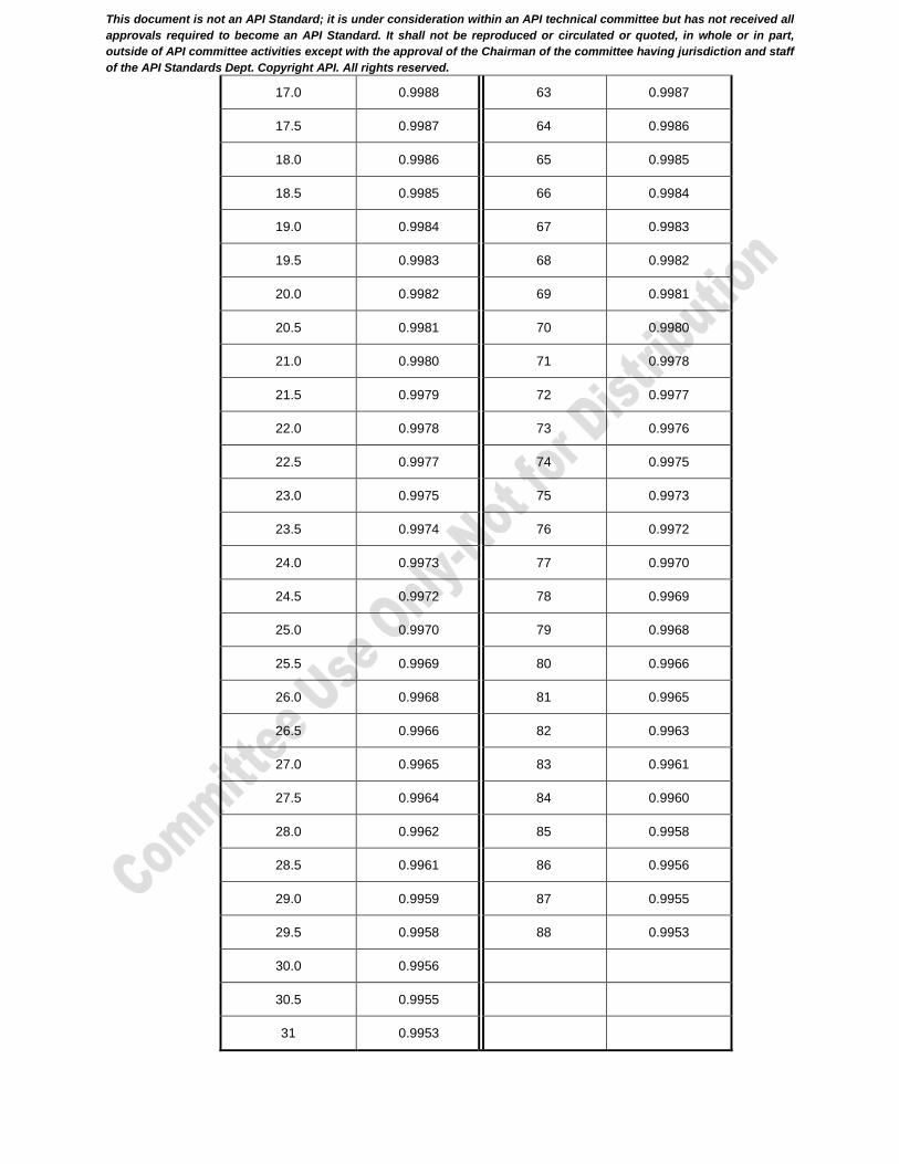
This document is not an API Standard; it is under consideration within an API technical committee but has not received all
approvals required to become an API Standard. It shall not be reproduced or circulated or quoted, in whole or in part,
outside of API committee activities except with the approval of the Chairman of the committee having jurisdiction and staff
of the API Standards Dept. Copyright API. All rights reserved.
17.0 0.9988 63 0.9987
17.5 0.9987 64 0.9986
18.0 0.9986 65 0.9985
18.5 0.9985 66 0.9984
19.0 0.9984 67 0.9983
19.5 0.9983 68 0.9982
20.0 0.9982 69 0.9981
20.5 0.9981 70 0.9980
21.0 0.9980 71 0.9978
21.5 0.9979 72 0.9977
22.0 0.9978 73 0.9976
22.5 0.9977 74 0.9975
23.0 0.9975 75 0.9973
23.5 0.9974 76 0.9972
24.0 0.9973 77 0.9970
24.5 0.9972 78 0.9969
25.0 0.9970 79 0.9968
25.5 0.9969 80 0.9966
26.0 0.9968 81 0.9965
26.5 0.9966 82 0.9963
27.0 0.9965 83 0.9961
27.5 0.9964 84 0.9960
28.0 0.9962 85 0.9958
28.5 0.9961 86 0.9956
29.0 0.9959 87 0.9955
29.5 0.9958 88 0.9953
30.0 0.9956
30.5 0.9955
31 0.9953
This document is not an API Standard; it is under consideration within an API technical committee but has not received all
approvals required to become an API Standard. It shall not be reproduced or circulated or quoted, in whole or in part,
outside of API committee activities except with the approval of the Chairman of the committee having jurisdiction and staff
of the API Standards Dept. Copyright API. All rights reserved.
C.3.15 Sieves
Sieves shall be in accordance with ASTM E11. A supplier's verification that a sieve conforms to ASTM E11 is satisfactory evidence of compliance. No periodic calibration of sieves is required.

This document is not an API Standard; it is under consideration within an API technical committee but has not received all
approvals required to become an API Standard. It shall not be reproduced or circulated or quoted, in whole or in part,
outside of API committee activities except with the approval of the Chairman of the committee having jurisdiction and staff
of the API Standards Dept. Copyright API. All rights reserved.
Annex D (informative)
Calibration Procedures for Thermocouples, Temperature Measuring
Systems, and Controllers
D.1 Calibration Methods
There are several satisfactory methods for calibrating thermocouples, including methods supplied by equipment manufacturers. See ASTM E220 for a more complete discussion of these procedures. No ASTM procedures for calibration of temperature measuring systems are available.
D.2 Thermocouple Calibration
D.2.1 Apparatus
D.2.1.1 General
The individual pieces of apparatus required to carry out the calibration depend on the particular technique selected. Those features that need special attention, regardless of the technique, are highlighted in C.2.1.2 to C.2.1.4.
D.2.1.2 Heating Environment
The heating medium should permit proper immersion of both the test thermocouple (the one being calibrated) and the reference thermocouple or reference thermometer. The apparatus should be capable of maintaining a stable temperature that is uniform throughout the test section.
D.2.1.3 Temperature Measurement
The reference temperature of the heating medium may be measured by using either a thermometer or a thermocouple. The accuracy of the reference measuring device should be traceable to the reference of the national body responsible for standards of temperature measurement, for example the NBS certification in the USA.
D.2.1.4 Thermocouple Voltage Output
If a thermocouple is used to sense the reference temperature, the voltage output from the reference thermocouple and test thermocouple should be determined as described in applicable national standards, such as ASTM E220. In this case, tables of temperature vs. voltage for the type of thermocouple being used should be consulted to determine the temperature. Alternatively, a direct-reading, temperature-compensated readout instrument may be used. The accuracy of the instrument should be traceable to national standards certification.
D.2.2 Procedure
With the exception of the indicating instruments, the specific procedures are detailed in applicable national standards, such as ASTM E220. The following items require special attention or are related to the use of the indicating type of equipment.
a) The test and reference thermocouples or thermometers should be placed as close together as possible in the heating medium.
b) After each change in heating level, the temperature should be allowed to remain at a stable value for 15 min before reading the reference temperature (or voltage) and the test thermocouple temperature (or voltage).
c) Several (more than three) test temperatures that span the operating range of the equipment should be used in the calibration procedure.
d) If the test thermocouple error is greater than that specified by the manufacturer, the thermocouple should be replaced by one that meets the thermocouple accuracy limits. The ASTM E230 classification “special” Type J thermocouple has error limits equal to or better than ±1 °C (±2 °F) up to 277 °C (530 °F).
This document is not an API Standard; it is under consideration within an API technical committee but has not received all
approvals required to become an API Standard. It shall not be reproduced or circulated or quoted, in whole or in part,
outside of API committee activities except with the approval of the Chairman of the committee having jurisdiction and staff
of the API Standards Dept. Copyright API. All rights reserved.
D.3 Calibration of Temperature Measuring Systems and Controllers
D.3.1 Apparatus
The calibration of temperature-measuring systems and controllers requires a millivolt source, the correct connecting thermocouple extension cable for the type of thermocouple being used and, possibly, a thermometer and a table of reference voltages. Signal sources, or calibrators, are of two types, namely, uncompensated and cold-junction-compensated. Several commercial calibrators are available that are cold-junction-compensated and have a digital display of the temperature equivalent to the millivolt signal being supplied. The accuracy of all calibration apparatus should be traceable to national-standards certification. Some older galvanometer-type temperature-indicating instruments and controllers require a stronger signal for operation than the newer potentiometric and digital-type temperature measuring systems and controllers and, therefore, require a calibrator with sufficient signal strength to give an accurate calibration.
D.3.2 Procedure
The manufacturer's procedure for calibrating temperature-measuring systems and controllers should be followed. The following items require special attention.
a) The thermocouple extension cable should be fitted with a proper thermocouple grade adapter to permit plugging it into the same receptacle used for connecting the test equipment thermocouple. Care should be taken to ensure the correct polarity of the connections. Calibrators, temperature-measuring systems, and controllers should be allowed proper warm-up time, as specified by the manufacturer, for greatest accuracy.
b) It is only necessary that thermocouple calibrators with cold-junction compensation be properly connected with the proper thermocouple extension cable and thermocouple connectors. The temperature-measuring systems and/or controllers using this signal should have the same temperature readout, within the accuracy of the temperature or controllers as supplied by the manufacturer.
c) Uncompensated thermocouple calibrators require a thermometer to determine the cold-junction temperature of the thermocouple extension cable connection of the calibrator. This cold-junction temperature is set on the calibrator by the operator.
The use of an uncompensated millivolt potentiometer requires that the temperature at the calibrator/thermocouple extension cable terminals be read with a thermometer of known accuracy. The millivolt equivalent of this temperature is then subtracted from the equivalent test millivolt signal to obtain the calibrator millivolt signal used. These voltages may be found in reference mV/temperature tables for the type of thermocouple in use.
This document is not an API Standard; it is under consideration within an API technical committee but has not received all
approvals required to become an API Standard. It shall not be reproduced or circulated or quoted, in whole or in part,
outside of API committee activities except with the approval of the Chairman of the committee having jurisdiction and staff
of the API Standards Dept. Copyright API. All rights reserved.
15
Bibliography
[1] API Spec Q1, Specification for Quality Management System Requirements for Manufacturing Organization for the Petroleum and Natural Gas Industry
[2] ASTM C150, Standard Specification for Portland Cement
[3] ASTM E220, Standard Test Method for Calibration of Thermocouples by Comparison Techniques
[4] ASTM E230/E230M-12 Standard Specification for Temperature-Electromotive Force (emf) Tables for Standardized Thermocouples
[5] ASTM C618, Standard Specification for Coal Fly Ash and Raw or Calcined Natural Pozzolan for Use in Concrete
[6] EN 196-2, Method of testing cement - Part 2 : Chemical analysis of cement
[7] EN 197-1, Cement. Composition, specifications and conformity criteria for common cements