ce 640 biotechnical production of ethanol - gunt · the plant control via plc will also help them...
TRANSCRIPT

ENERGY & ENV IRONMENT
2E a division of
E Q U I P M E N T F O R E N G I N E E R I N G E D U C A T I O N
CE 640 Biotechnical Production of Ethanol
Energy from renewable raw materials
© 2014 G.U.N.T. Gerätebau GmbH
Scan to watch the video about„Operation and Experiment with CE 640“
The experimental plant for the biotechnical production of ethanol is ideally suited for training students and professionals in chemical and biochemical engi-neering. The plant has been designed to perform a wide range of didactic topics. Bioethanol is, and will remain, the leading biofuel worldwide. Students will get to know the entire process, starting with the raw materials up to the end product.
Various processes, such as shredding, fermentation and distillation, can be studied. Conditions and possibilities for the technological, material and the energetic combination of processes in a method can be conveyed.
Technicians and engineers are always faced with the same questions: What needs to be measured, regulated and controlled, where and how? This plant is ideally suited to provide the answers.
The experimental plant demonstrates a functional and elegant solution to equipment design. I know from experience that trainees and students will appreciate the level of detail that has gone into designing the plant. The plant control via PLC will also help them to learn to operate large technical systems.
Prof. Dr.-Ing.habil Kurt Gramlich University of Applied Sciences Anhalt
CE 640 Developing the bioethanol production in the laboratory
Energy and environment are essential for a sustainable development
“The next 10 years will be critical for the future of our planet. Radical measures must be taken both on climate change mitigation and adaptation before we are locked into potentially irreversible, catastrophic climate transformations, whose impacts are expected to substantially change the environment and our lives on this planet.”
Excerpt from the United Nations Development Programme Charting A New Low-Carbon Route To Development Yannik Glemarec
Engineers, scientists, technicians and experienced specialists will play an important role in the transition to sustainable development. They will need a sound education which includes practical experience.
GUNT is a leader in the development of innovative education and training systems for sustainable energy production and environmental pollution control.
The importance of water for the protection of health and the environment is highlighted by our complete programme of experimental units for water treatment.
B I O E T H A N O L P R O D U C T I O N I N T H E L A B O R AT O R Y E X P E R I M E N T
CONTENTSEnergy from Biomass 3
Biotechnical Production of Ethanol 4
CE 640 – Schematic Process 5
CE 640 – Plant Design 6
CE 640 – Technology and Components 7
CE 640 – The Automation and Measuring Technology Plant Concept 8
CE 640 – Installation and Space Requirements of the Plant 9
CE 640 in the Lab at Münster University of Applied Sciences 10
CE 640 at the Agricultural Research Institute Nicosia 11
Didactic Concept, Installation and Training 11
2E Philosophy 12
2
ENERGY & ENV IRONMENT
Development of bioenergy sources
The CO2 cycle of bioethanol
Bioethanol as an alternative
to fossil fuels
The following points outline the importance of bioetha-nol as an alternative energy source:
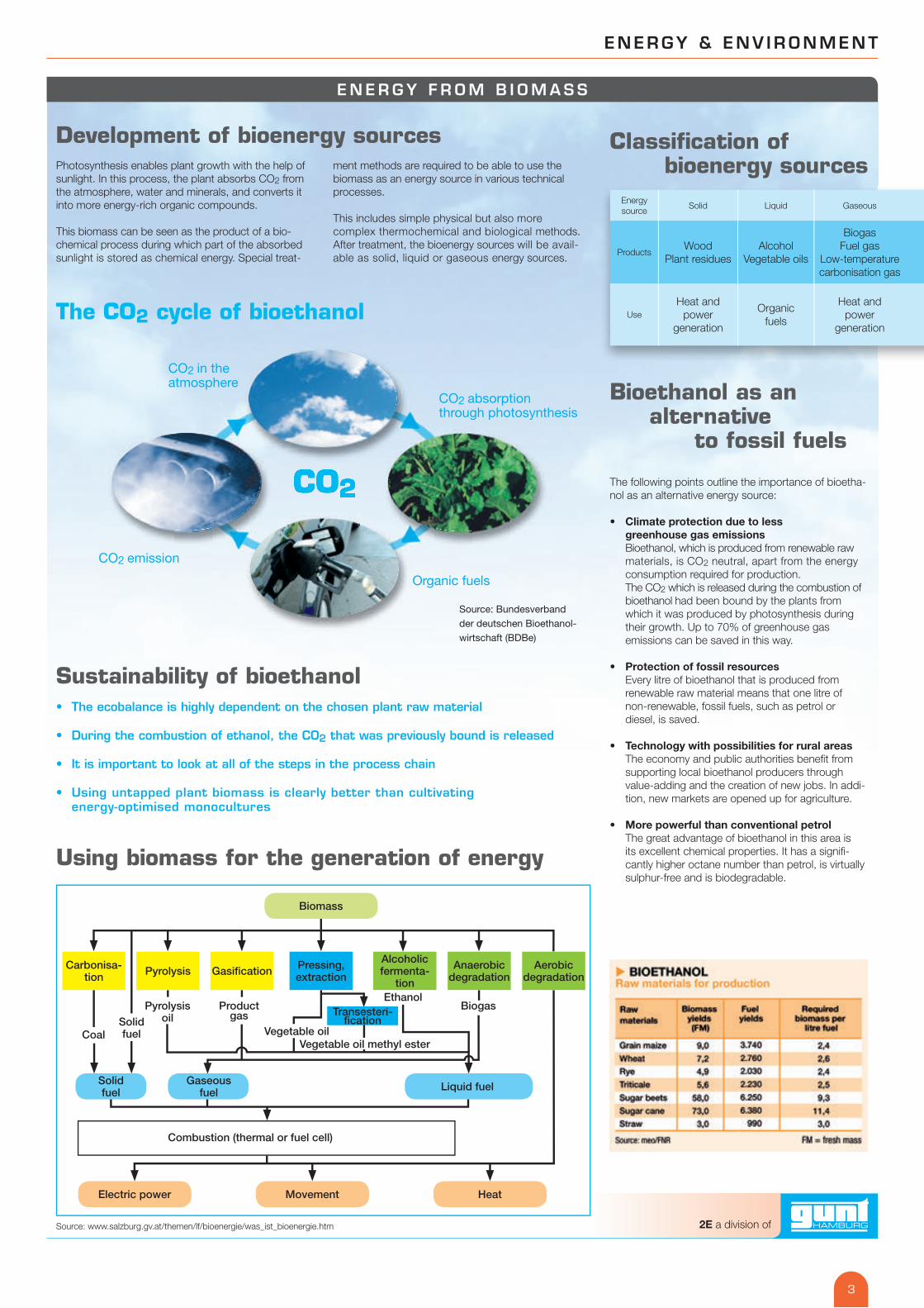
• Climate protection due to less greenhouse gas emissions Bioethanol, which is produced from renewable raw materials, is CO2 neutral, apart from the energy consumption required for production. The CO2 which is released during the combustion of bioethanol had been bound by the plants from which it was produced by photosynthesis during their growth. Up to 70% of greenhouse gas emissions can be saved in this way.
• Protection of fossil resources Every litre of bioethanol that is produced from renewable raw material means that one litre of non-renewable, fossil fuels, such as petrol or diesel, is saved.
• Technology with possibilities for rural areas The economy and public authorities bene� t from supporting local bioethanol producers through value-adding and the creation of new jobs. In addi-tion, new markets are opened up for agriculture.
• More powerful than conventional petrol The great advantage of bioethanol in this area is its excellent chemical properties. It has a signi� -cantly higher octane number than petrol, is virtually sulphur-free and is biodegradable.
Classifi cation of bioenergy sources
Sustainability of bioethanol • The ecobalance is highly dependent on the chosen plant raw material
• During the combustion of ethanol, the CO2 that was previously bound is released
• It is important to look at all of the steps in the process chain
• Using untapped plant biomass is clearly better than cultivating energy-optimised monocultures
Source: www.salzburg.gv.at/themen/lf/bioenergie/was_ist_bioenergie.htm
Using biomass for the generation of energy
E N E R G Y F R O M B I O M A S S
Photosynthesis enables plant growth with the help of sunlight. In this process, the plant absorbs CO2 from the atmosphere, water and minerals, and converts it into more energy-rich organic compounds.
This biomass can be seen as the product of a bio-chemical process during which part of the absorbed sunlight is stored as chemical energy. Special treat-
ment methods are required to be able to use the biomass as an energy source in various technical processes.
This includes simple physical but also more complex thermochemical and biological methods. After treatment, the bioenergy sources will be avail-able as solid, liquid or gaseous energy sources.
Energy source
Solid Liquid Gaseous
ProductsWood
Plant residuesAlcohol
Vegetable oils
BiogasFuel gas
Low-temperature carbonisation gas
UseHeat and
powergeneration
Organic fuels
Heat andpower
generation
Carbonisa-tion Pyrolysis Gasi� cation Pressing,
extraction
Alcoholicfermenta-
tion
Aerobic degradation
Anaerobicdegradation
Biomass
Electric power Movement Heat
Combustion (thermal or fuel cell)
Solidfuel
Gaseousfuel Liquid fuel
CoalSolidfuel
Pyrolysisoil
Productgas
Vegetable oilVegetable oil methyl ester
EthanolBiogasTransesteri-
� cation
CO2CO2
CO2 emission
CO2 in the atmosphere
CO2 absorptionthrough photosynthesis
Organic fuels
Source: Bundesverband der deutschen Bioethanol-wirtschaft (BDBe)
3
2E a division of
A gigantic distillery
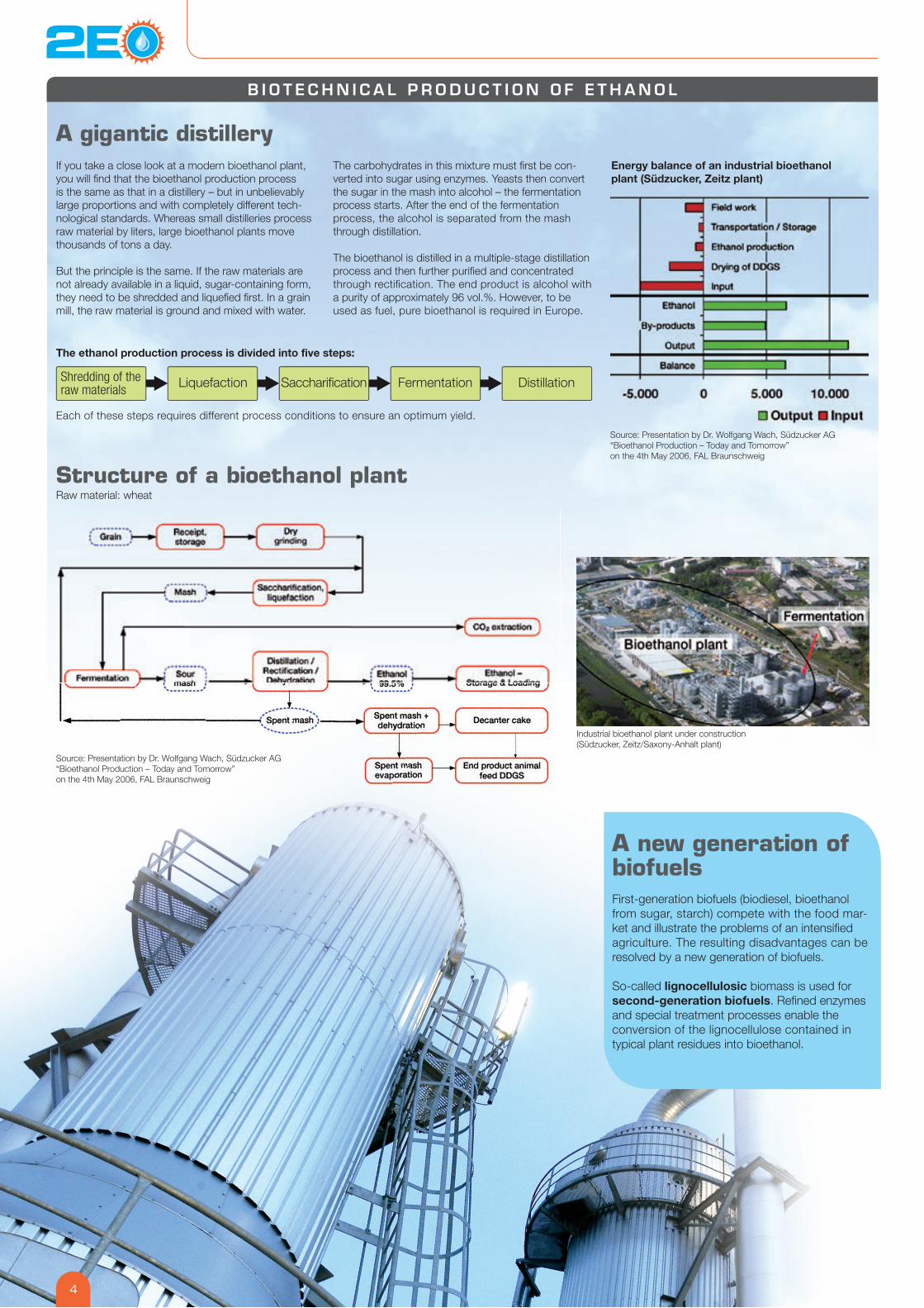
Structure of a bioethanol plantRaw material: wheat
If you take a close look at a modern bioethanol plant, you will � nd that the bioethanol production process is the same as that in a distillery – but in unbelievably large proportions and with completely different tech-nological standards. Whereas small distilleries process raw material by liters, large bioethanol plants move thousands of tons a day.
But the principle is the same. If the raw materials are not already available in a liquid, sugar-containing form, they need to be shredded and lique� ed � rst. In a grain mill, the raw material is ground and mixed with water.
The carbohydrates in this mixture must � rst be con-verted into sugar using enzymes. Yeasts then convert the sugar in the mash into alcohol – the fermentation process starts. After the end of the fermentation process, the alcohol is separated from the mash through distillation.
The bioethanol is distilled in a multiple-stage distillation process and then further puri� ed and concentrated through recti� cation. The end product is alcohol with a purity of approximately 96 vol.%. However, to be used as fuel, pure bioethanol is required in Europe.
The ethanol production process is divided into five steps:
Each of these steps requires different process conditions to ensure an optimum yield.
A new generation of biofuels First-generation biofuels (biodiesel, bioethanol from sugar, starch) compete with the food mar-ket and illustrate the problems of an intensi� ed agriculture. The resulting disadvantages can be resolved by a new generation of biofuels.
So-called lignocellulosic biomass is used for second-generation biofuels. Re� ned enzymes and special treatment processes enable the conversion of the lignocellulose contained in typical plant residues into bioethanol.
Energy balance of an industrial bioethanolplant (Südzucker, Zeitz plant)
Source: Presentation by Dr. Wolfgang Wach, Südzucker AG “Bioethanol Production – Today and Tomorrow” on the 4th May 2006, FAL Braunschweig
Source: Presentation by Dr. Wolfgang Wach, Südzucker AG “Bioethanol Production – Today and Tomorrow” on the 4th May 2006, FAL Braunschweig
B I O T E C H N I C A L P R O D U C T I O N O F E T H A N O L
Industrial bioethanol plant under construction (Südzucker, Zeitz/Saxony-Anhalt plant)
Shredding of the raw materials Liquefaction Sacchari� cation Fermentation Distillation
4
ENERGY & ENV IRONMENT
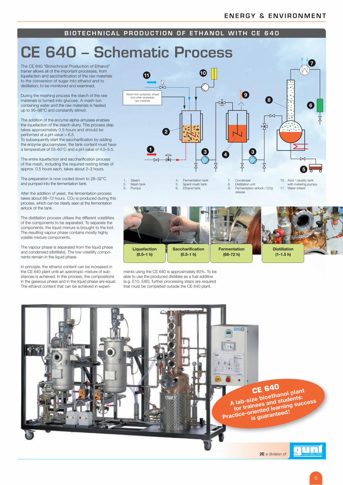
The CE 640 “Biotechnical Production of Ethanol” trainer allows all of the important processes, from liquefaction and sacchari� cation of the raw materials to the conversion of sugar into ethanol and to distillation, to be monitored and examined.
During the mashing process the starch of the raw materials is turned into glucose. A mash-tun containing water and the raw materials is heated up to 95–98°C and constantly stirred.
The addition of the enzyme alpha-amylase enables the liquefaction of the starch slurry. This process step takes approximately 0.5 hours and should be performed at a pH value > 6.5. To subsequently start the sacchari� cation by adding the enzyme glucoamylase, the tank content must have a temperature of 55–60°C and a pH value of 4.5–5.5.
The entire liquefaction and sacchari� cation process of the mash, including the required resting times of approx. 0.5 hours each, takes about 2–3 hours.
The preparation is now cooled down to 28–32°C and pumped into the fermentation tank.
After the addition of yeast, the fermentation process takes about 68–72 hours. CO2 is produced during this process, which can be clearly seen at the fermentation airlock of the tank.
The distillation process utilises the different volatilities of the components to be separated. To separate the components, the liquid mixture is brought to the boil. The resulting vapour phase contains mostly highly volatile mixture components.
The vapour phase is separated from the liquid phase and condensed (distillate). The low-volatility compo-nents remain in the liquid phase.
In principle, the ethanol content can be increased in the CE 640 plant until an azeotropic mixture of sub-stances is achieved. In this process, the compositions in the gaseous phase and in the liquid phase are equal. The ethanol content that can be achieved in experi-
CE 640
A lab-size bioethanol plant
for trainees and students:
Practice-oriented learning success
is guaranteed!
B I O T E C H N I C A L P R O D U C T I O N O F E T H A N O L W I T H C E 6 4 0
1
2
3 4
5
3
6
7
89
1011
ments using the CE 640 is approximately 80%. To be able to use the produced distillate as a fuel additive (e.g. E10, E85), further processing steps are required that must be completed outside the CE 640 plant.
1. Steam 2. Mash tank 3. Pumps
4. Fermentation tank 5. Spent mash tank 6. Ethanol tank
7. Condenser 8. Distillation unit 9. Fermentation airlock / CO2
release
10. Acid / caustic tank with metering pumps
11. Water infeed
Liquefaction(0.5–1 h)
Fermentation(68-72 h)
Distillation(1-1.5 h)
Saccharification(0.5-1 h)
CE 640 – Schematic Process
Starch from potatoes, wheatand other renewable
raw materials
5
2E a division of
B I O T E C H N I C A L P R O D U C T I O N O F E T H A N O L W I T H C E 6 4 0
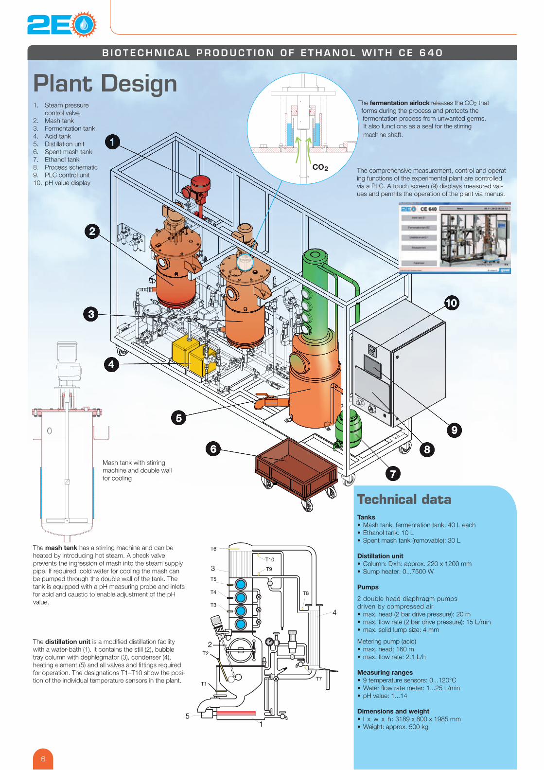
Plant DesignThe fermentation airlock releases the CO2 that forms during the process and protects the fermentation process from unwanted germs. It also functions as a seal for the stirring machine shaft.
The comprehensive measurement, control and operat-ing functions of the experimental plant are controlled via a PLC. A touch screen (9) displays measured val-ues and permits the operation of the plant via menus.
T1
T2
T10
T9
T8
T6
T7
T3
T4
T5
1
2
3
4
5
The mash tank has a stirring machine and can be heated by introducing hot steam. A check valve prevents the ingression of mash into the steam supply pipe. If required, cold water for cooling the mash can be pumped through the double wall of the tank. The tank is equipped with a pH measuring probe and inlets for acid and caustic to enable adjustment of the pH value.
The distillation unit is a modi� ed distillation facility with a water-bath (1). It contains the still (2), bubble tray column with dephlegmator (3), condenser (4), heating element (5) and all valves and � ttings required for operation. The designations T1–T10 show the posi-tion of the individual temperature sensors in the plant.
Technical dataTanks• Mash tank, fermentation tank: 40 L each• Ethanol tank: 10 L• Spent mash tank (removable): 30 L
Distillation unit• Column: Dxh: approx. 220 x 1200 mm• Sump heater: 0...7500 W
Pumps
2 double head diaphragm pumps driven by compressed air• max. head (2 bar drive pressure): 20 m• max. � ow rate (2 bar drive pressure): 15 L/min• max. solid lump size: 4 mm
Metering pump (acid)• max. head: 160 m• max. � ow rate: 2.1 L/h
Measuring ranges• 9 temperature sensors: 0...120°C• Water � ow rate meter: 1...25 L/min• pH value: 1...14
Dimensions and weight• l x w x h: 3189 x 800 x 1985 mm• Weight: approx. 500 kg
Mash tank with stirring machine and double wall for cooling
1. Steam pressure control valve
2. Mash tank3. Fermentation tank4. Acid tank5. Distillation unit6. Spent mash tank7. Ethanol tank8. Process schematic9. PLC control unit10. pH value display
CO
2
6
ENERGY & ENV IRONMENT
B I O T E C H N I C A L P R O D U C T I O N O F E T H A N O L W I T H C E 6 4 0
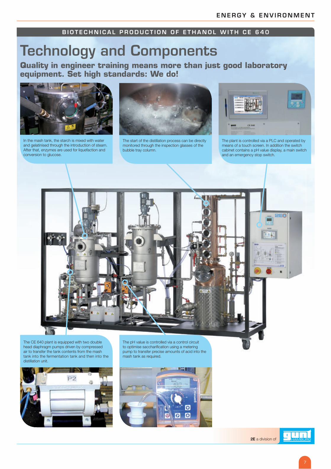
Technology and ComponentsQuality in engineer training means more than just good laboratory equipment. Set high standards: We do!
In the mash tank, the starch is mixed with water and gelatinised through the introduction of steam. After that, enzymes are used for liquefaction and conversion to glucose.
The CE 640 plant is equipped with two double head diaphragm pumps driven by compressed air to transfer the tank contents from the mash tank into the fermentation tank and then into the distillation unit.
The pH value is controlled via a control circuit to optimise sacchari� cation using a metering pump to transfer precise amounts of acid into the mash tank as required.
The start of the distillation process can be directly monitored through the inspection glasses of the bubble tray column.
The plant is controlled via a PLC and operated by means of a touch screen. In addition the switch cabinet contains a pH value display, a main switch and an emergency stop switch.
7
2E a division of
B I O T E C H N I C A L P R O D U C T I O N O F E T H A N O L W I T H C E 6 4 0
The Automation and Measuring Technology Plant ConceptThe main educational area is biochemical engineering. It also teaches the basics of modern automation technology. This plant offers many interesting possibilities to do so.
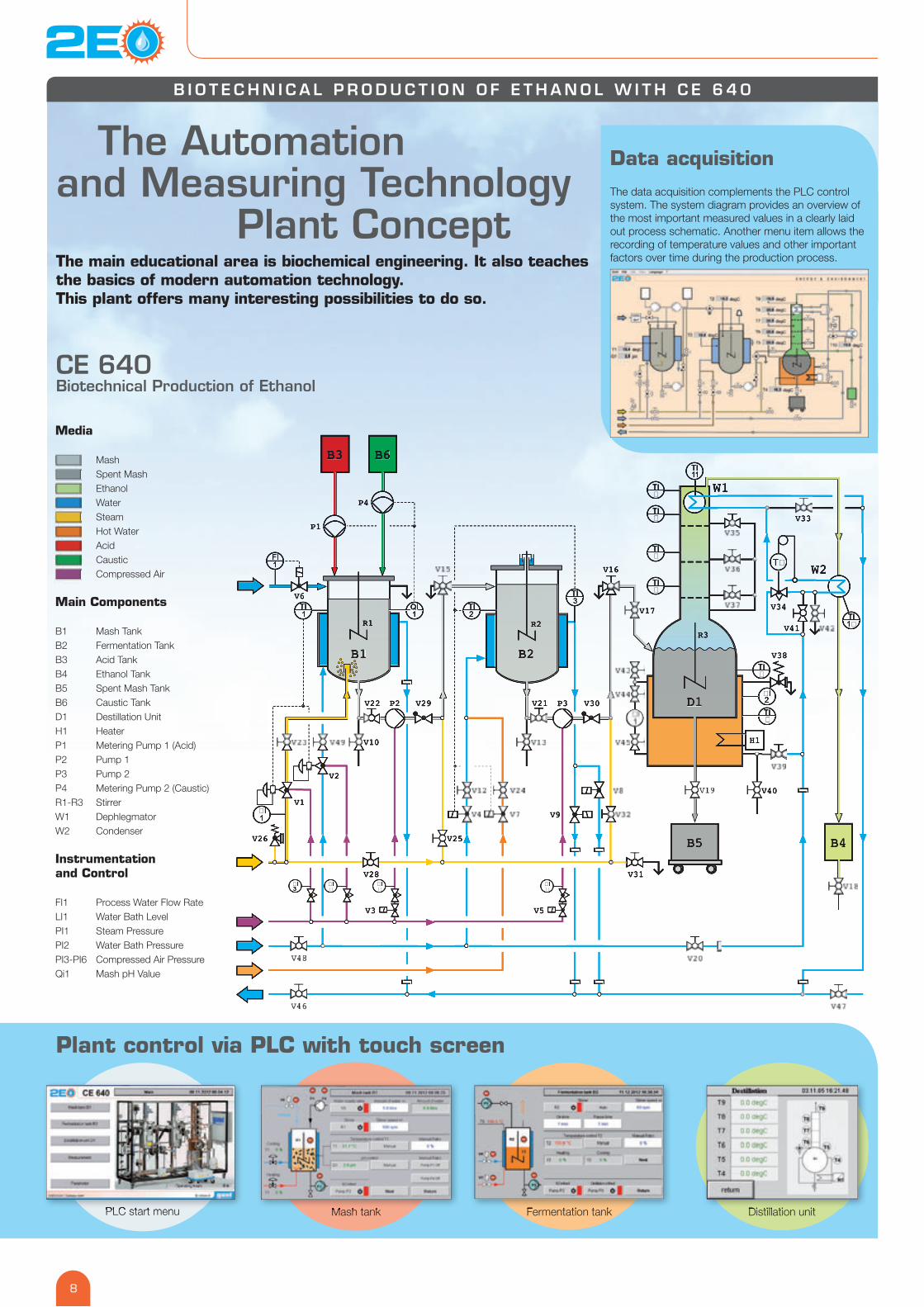
Data acquisition The data acquisition complements the PLC control system. The system diagram provides an overview of the most important measured values in a clearly laid out process schematic. Another menu item allows the recording of temperature values and other important factors over time during the production process.
Plant control via PLC with touch screen
PLC start menu Mash tank Fermentation tank Distillation unit
Media
Mash Spent Mash Ethanol Water Steam Hot Water Acid Caustic Compressed Air
Main Components
B1 Mash TankB2 Fermentation TankB3 Acid TankB4 Ethanol TankB5 Spent Mash TankB6 Caustic TankD1 Destillation UnitH1 HeaterP1 Metering Pump 1 (Acid)P2 Pump 1P3 Pump 2P4 Metering Pump 2 (Caustic)R1-R3 StirrerW1 DephlegmatorW2 Condenser
Instrumentation and Control
FI1 Process Water Flow RateLI1 Water Bath LevelPI1 Steam PressurePI2 Water Bath PressurePI3-PI6 Compressed Air PressureQi1 Mash pH Value
PLC start menu Mash tank Fermentation tank Distillation unit
Mash Spent Mash Ethanol Water Steam Hot Water Acid Caustic Compressed Air
TI3
FI1
QI1
TI1
TI2
�I�
�I�
�I3
�I�
TI�
TI�
TI�
TI�
�I2TI�
TI�
TI11
�I1
T�
TI1�1�
R3
D1D1
B3 B6
W2
B4
P2 P3
P4
P1
W1
B5
H1
B1
R1
B2
R2
V6
V1
V10
V2
V21 V30
V16
V17
V33
V34
V41
V29V22
V3 V5
V38
V40
V25V26
V28 V31
V9
CE 640Biotechnical Production of Ethanol
8
ENERGY & ENV IRONMENT
I N S TA L L AT I O N A N D S PA C E R E Q U I R E M E N T S O F T H E P L A N T
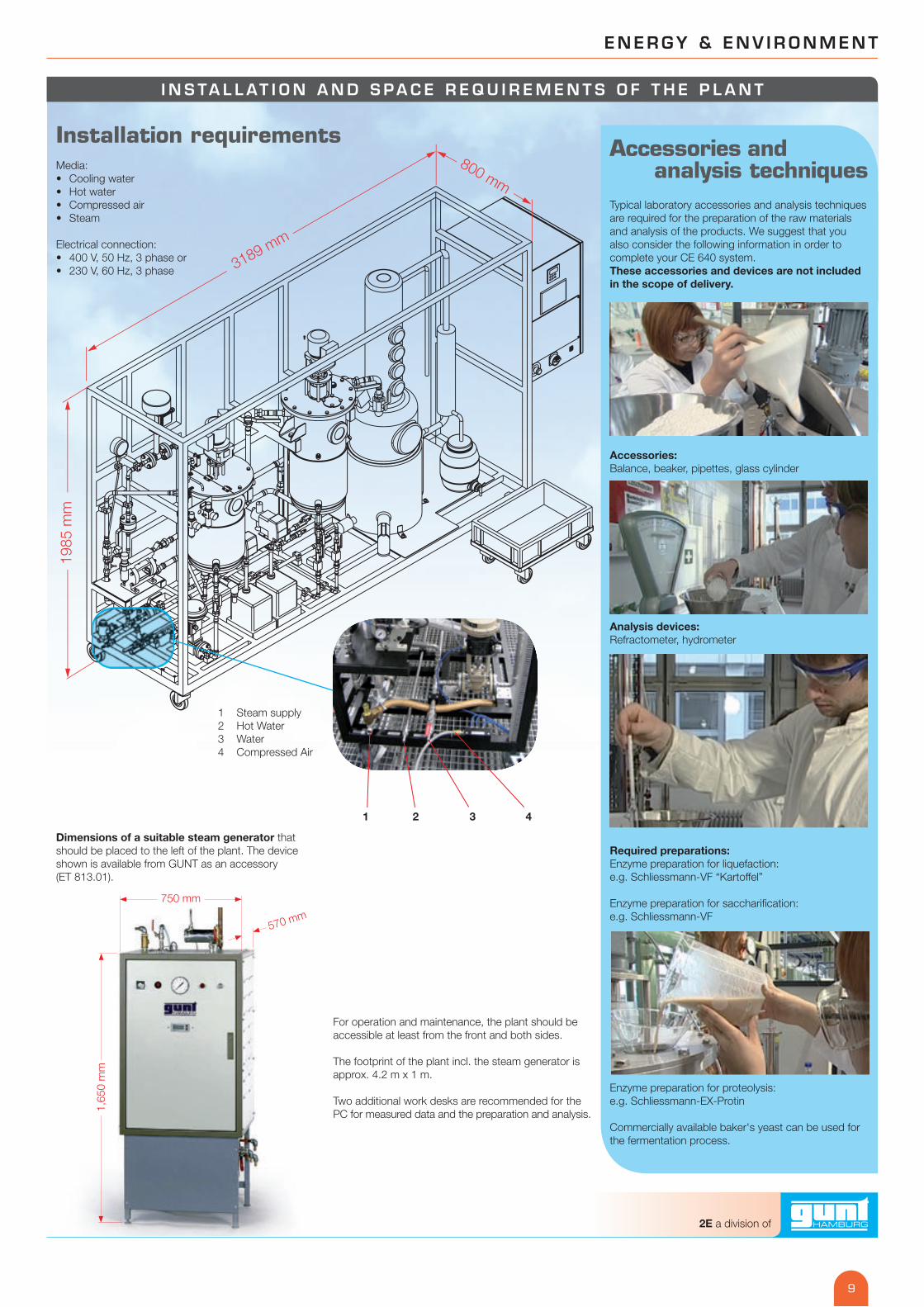
Installation requirementsMedia:• Cooling water• Hot water• Compressed air• Steam
Electrical connection:• 400 V, 50 Hz, 3 phase or • 230 V, 60 Hz, 3 phase
1 Steam supply2 Hot Water 3 Water4 Compressed Air
Accessories and analysis techniques
Typical laboratory accessories and analysis techniques are required for the preparation of the raw materials and analysis of the products. We suggest that you also consider the following information in order to complete your CE 640 system. These accessories and devices are not included in the scope of delivery.
Accessories: Balance, beaker, pipettes, glass cylinder
Analysis devices: Refractometer, hydrometer
Required preparations: Enzyme preparation for liquefaction: e.g. Schliessmann-VF “Kartoffel”
Enzyme preparation for sacchari� cation: e.g. Schliessmann-VF
Enzyme preparation for proteolysis: e.g. Schliessmann-EX-Protin
Commercially available baker's yeast can be used for the fermentation process.
For operation and maintenance, the plant should be accessible at least from the front and both sides.
The footprint of the plant incl. the steam generator is approx. 4.2 m x 1 m.
Two additional work desks are recommended for the PC for measured data and the preparation and analysis.
Dimensions of a suitable steam generator that should be placed to the left of the plant. The device shown is available from GUNT as an accessory (ET 813.01).
1,65
0 m
m
750 mm
570 mm
1 2 3 4
3189 mm
800
mm
1985
mm
9
2E a division of
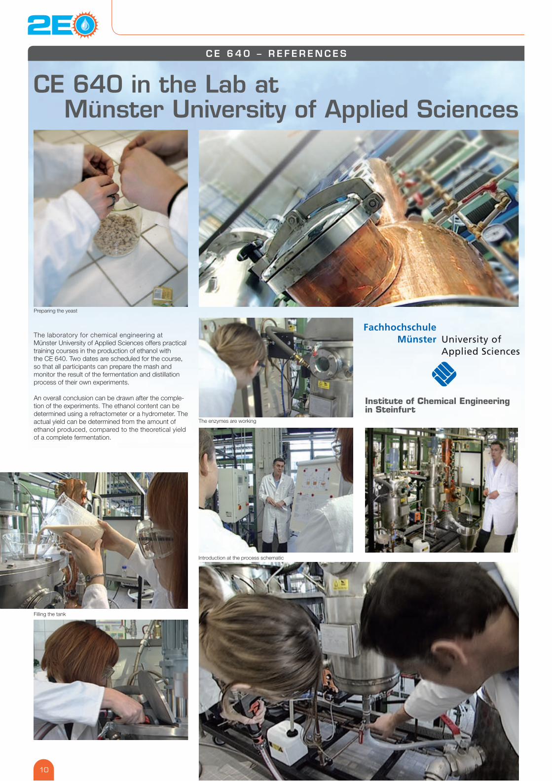
The laboratory for chemical engineering at Münster University of Applied Sciences offers practical training courses in the production of ethanol with the CE 640. Two dates are scheduled for the course, so that all participants can prepare the mash and monitor the result of the fermentation and distillation process of their own experiments.
An overall conclusion can be drawn after the comple-tion of the experiments. The ethanol content can be determined using a refractometer or a hydrometer. The actual yield can be determined from the amount of ethanol produced, compared to the theoretical yield of a complete fermentation.
C E 6 4 0 – R E F E R E N C E S
CE 640 in the Lab at Münster University of Applied Sciences
Filling the tank
Preparing the yeast
The enzymes are working
Introduction at the process schematic
Institute of Chemical Engineeringin Steinfurt
10
ENERGY & ENV IRONMENT
The CE 640 Biotechnical Production of Ethanol trainer has been developed by GUNT for use in vocational schools, universities of applied sciences and research institutes. The plant concept clearly shows the individual steps of the production of ethanol and enables to understand the functioning of the required plant components. The users will get to know the meaning of the process parameters and will be able to see the effects of system changes after an introduction.
A variety of raw materials can be used as starch sources in processes that can be carried out in different ways, the � exible concept behind the trainer allows to investigate the optimisation of process parameters for later large-scale applications.
Learning objectives – biochemical engineering
Familiarisation with the necessary individual steps and plant components for the production of alcohol:
• Gelatinisation by steam injection • Liquefaction by use of alpha-amylase • Sacchari� cation by use of glucoamylase • Fermentation: conversion of sugar into ethanol by
yeast cultures under anaerobic conditions • Distillation in batch operation:
separation of ethanol from the mash
Experiments – plant operation and automation
• Process control via PLC• Using touch screen control
in automation technology• Controlling the temperature in the mash tank • Controlling the pH value in the mash tank• Controlling the fermentation temperature and the
column head temperature during distillation• Setting the control parameters• Controlling the stirrer speed • Controlling the mash pump
and fermentation tank pump• Monitoring of all relevant measured data
via PC• Data acquisition and processing
in tables and � les
Educational support materialThe comprehensive instructions offer: • Explanation of the basics • Description of the unit • Reference experiments • Original instructions by the manufacturers
of the integrated components • Data sheets for the recommended enzymes
Updates: GUNT will inform its customers if improve-ments or additions are available for the CE 640 trainer – especially regarding the educational material and the software.
Training for teachers
We recommend a multi-day training course by a quali� ed GUNT engineer. This will help you to make the most of your new bioethanol experimental plant in no time at all.
Plant installation Have the plant installed and commissioned by a quali� ed GUNT specialist.
Didactic Concept, Installation and Training
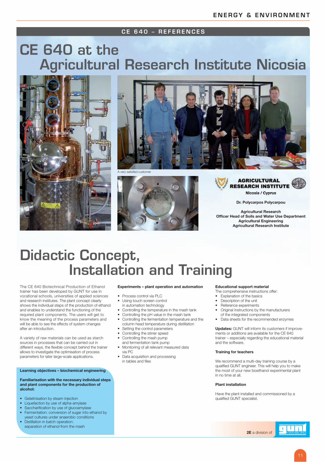
Nicosia / Cyprus
Dr. Polycarpos Polycarpou
Agricultural Research Of� cer Head of Soils and Water Use Department
Agricultural Engineering Agricultural Research Institute
C E 6 4 0 – R E F E R E N C E S
CE 640 at the Agricultural Research Institute Nicosia
A very satis� ed customer
Nicosia / Cyprus
11
2E a division of
Visit our website
www.gunt.de
The 2E philosophy2E is a logo, an abbreviation of ENERGY and ENVIRONMENT. And, as always with GUNT, it is about technical education and training systems.
The objective is to get trainees and students acquaint-ed with subjects they are likely to face in practice. 2E expresses our integrated concept: questions regard-ing energy (renewable energy, of course) cannot be separated from environmental topics.
For example, if we produce ethanol with our CE 640 plant, we need electric energy, steam, water and com-pressed air for this process. We release CO2 into the environment, and heat losses occur. Process residues (spent mash, water) must be disposed or used.
This integrated concept – one might also call it an ecological concept – is one of the key elements of the 2E philosophy.
Another important element of the GUNT 2E philosophy
Through experiments and research projects with our experimental plants, we want to provide trainees and students with a solid foundation for the future. This foundation, made of basic technological know-how and facts, will give them good competence for the future and provide a sound basis to make their own decisions.
We do not represent any speci� c interest groups and do not favour any speci� c technology. We are not engaged in any lobby work or politics; we provide basic knowledge for technicians and engineers and are here to help develop and improve competence in this important � eld.
How to get in touchVisit us on the Internet at www.gunt.de
Visit our plant in Hamburg
We can visit you at your school and give you individual and competent advice
We can give a presentation on selected topics for you and your colleagues at your school
G U N T 2 E – C O N C E P T
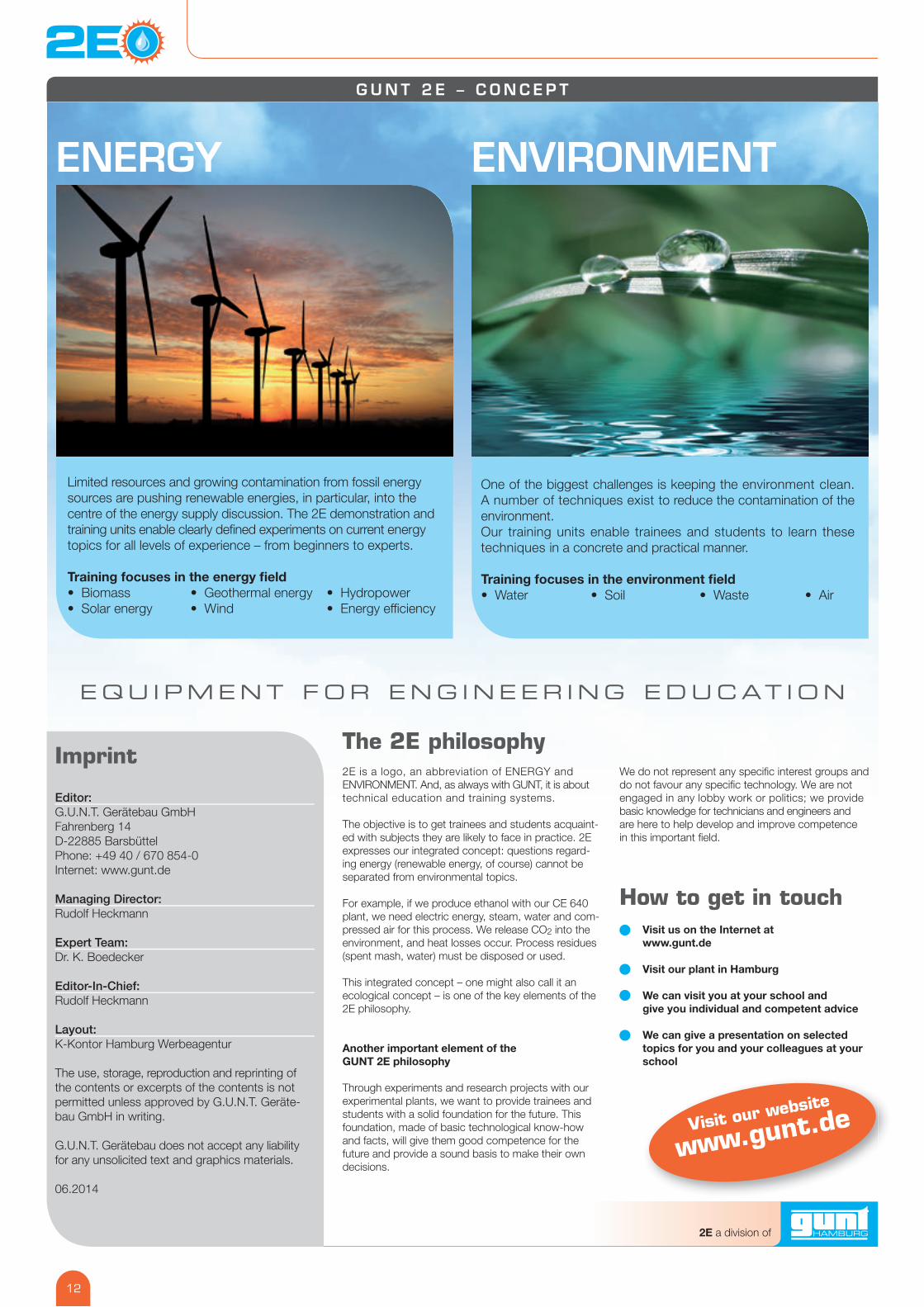
ENVIRONMENTENERGY
Limited resources and growing contamination from fossil energy sources are pushing renewable energies, in particular, into the centre of the energy supply discussion. The 2E demonstration and training units enable clearly de� ned experiments on current energy topics for all levels of experience – from beginners to experts.
Training focuses in the energy � eld• Biomass • Geothermal energy • Hydropower• Solar energy • Wind • Energy effi ciency
One of the biggest challenges is keeping the environment clean. A number of techniques exist to reduce the contamination of the environment. Our training units enable trainees and students to learn these techniques in a concrete and practical manner.
Training focuses in the environment � eld• Water • Soil • Waste • Air
EQU I PMENT FOR ENG INEER ING EDUCAT ION
Editor: G.U.N.T. Gerätebau GmbHFahrenberg 14 D-22885 BarsbüttelPhone: +49 40 / 670 854-0Internet: www.gunt.de
Managing Director: Rudolf Heckmann
Expert Team: Dr. K. Boedecker
Editor-In-Chief: Rudolf Heckmann
Layout: K-Kontor Hamburg Werbeagentur
The use, storage, reproduction and reprinting of the contents or excerpts of the contents is not permitted unless approved by G.U.N.T. Geräte-bau GmbH in writing.
G.U.N.T. Gerätebau does not accept any liability for any unsolicited text and graphics materials.
06.2014
Imprint
12
2E a division of