ccna1-1 chapter 5 osi network layer. ccna1-2 chapter 5 osi network layer internet protocol version 4...
TRANSCRIPT
CCNA1-1 Chapter 5
Chapter 5Chapter 5
OSI Network LayerOSI Network Layer
CCNA1-2 Chapter 5
OSI Network LayerOSI Network Layer
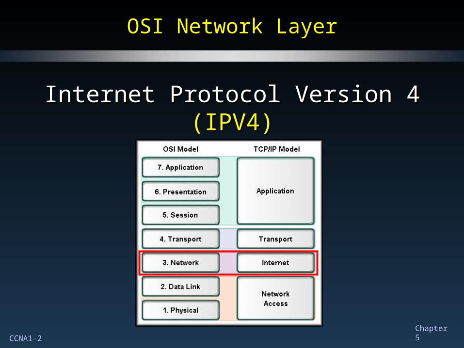
Internet Protocol Version 4 Internet Protocol Version 4 (IPV4)(IPV4)
CCNA1-3 Chapter 5
Communication from Host to HostCommunication from Host to Host
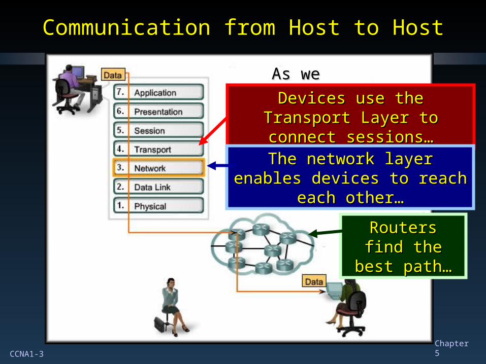
As we communicate…As we communicate…
Devices use the Transport Layer Devices use the Transport Layer to connect sessions…to connect sessions…
The network layer enables The network layer enables devices to reach each other…devices to reach each other…
Routers find the Routers find the best path…best path…
CCNA1-4 Chapter 5
Communication from Host to HostCommunication from Host to Host
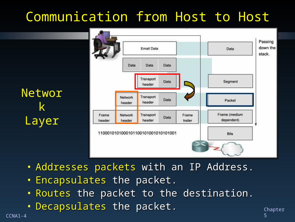
• Addresses packets Addresses packets with an IP Address.with an IP Address.• Encapsulates Encapsulates the packet.the packet.• RoutesRoutes the packet to the destination. the packet to the destination.• DecapsulatesDecapsulates the packet. the packet.
NetworkLayer
CCNA1-5 Chapter 5
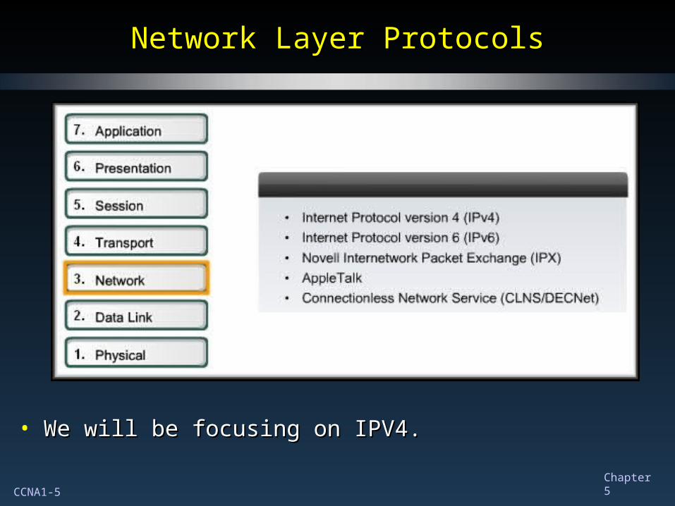
Network Layer ProtocolsNetwork Layer Protocols
• We will be focusing on IPV4.We will be focusing on IPV4.
CCNA1-6 Chapter 5
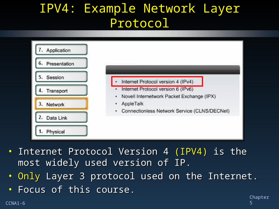
IPV4: Example Network Layer ProtocolIPV4: Example Network Layer Protocol
• Internet Protocol Version 4 Internet Protocol Version 4 (IPV4) (IPV4) is the most widely used is the most widely used version of IP.version of IP.
• OnlyOnly Layer 3 protocol used on the Internet. Layer 3 protocol used on the Internet.• Focus of this course.Focus of this course.

CCNA1-7 Chapter 5
IPV4: Example Network Layer ProtocolIPV4: Example Network Layer Protocol
• Internet Protocol Version 6 Internet Protocol Version 6 (IPV6) (IPV6) is developed and slowly is developed and slowly being implemented. being implemented. (More in CCNA-4)(More in CCNA-4)
• Will eventually replace IPV4.Will eventually replace IPV4.• Different characteristics than IPV4.Different characteristics than IPV4.
CCNA1-8 Chapter 5
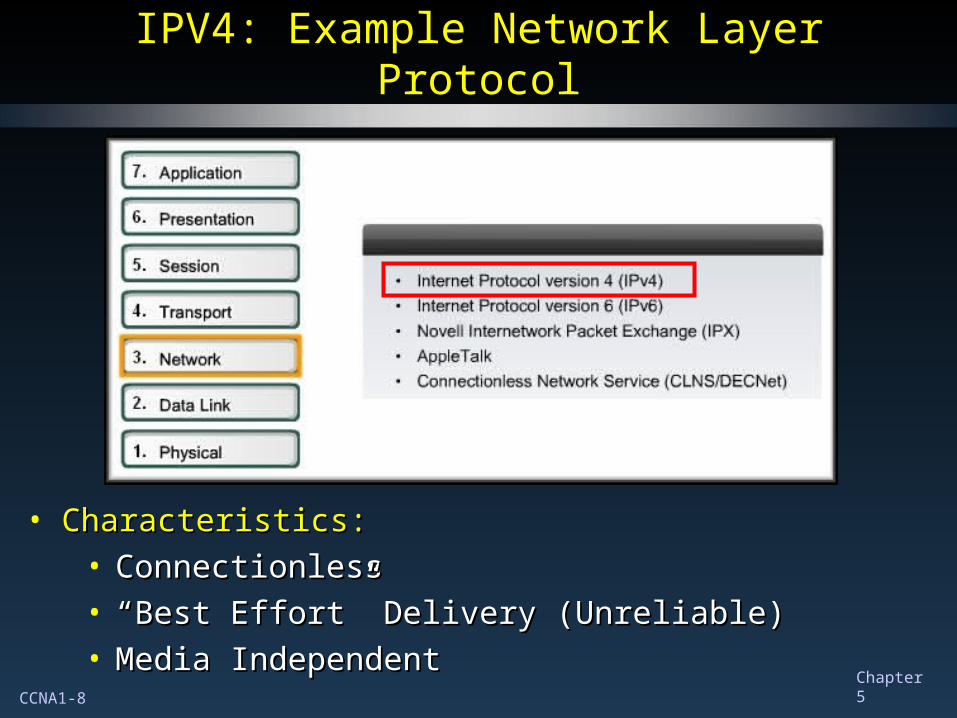
IPV4: Example Network Layer ProtocolIPV4: Example Network Layer Protocol
• Characteristics:Characteristics:• ConnectionlessConnectionless• ““Best Effort” Delivery (Unreliable)Best Effort” Delivery (Unreliable)• Media IndependentMedia Independent
CCNA1-9 Chapter 5
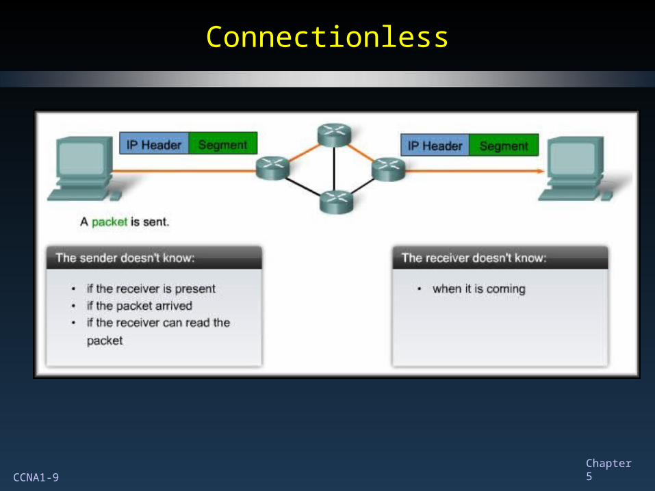
ConnectionlessConnectionless
CCNA1-10 Chapter 5
““Best Effort” Delivery (Unreliable)Best Effort” Delivery (Unreliable)
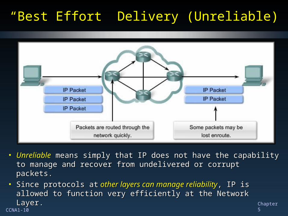
• UnreliableUnreliable means simply that IP does not have the capability means simply that IP does not have the capability to manage and recover from undelivered or corrupt packets.to manage and recover from undelivered or corrupt packets.
• Since protocols atSince protocols at other layers can manage reliability other layers can manage reliability, IP is , IP is allowed to function very efficiently at the Network Layer. allowed to function very efficiently at the Network Layer.
CCNA1-11 Chapter 5
Media IndependentMedia Independent
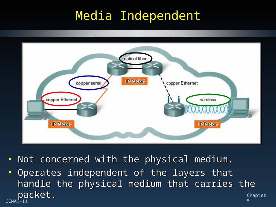
• Not concerned with the physical medium.Not concerned with the physical medium.• Operates independent of the layers that handle the physical Operates independent of the layers that handle the physical
medium that carries the packet.medium that carries the packet.
CCNA1-12 Chapter 5
Media IndependentMedia Independent
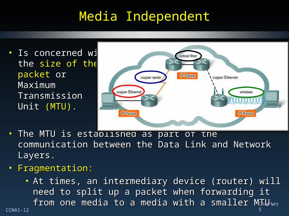
• Is concerned withIs concerned withthe the size of thesize of thepacketpacket or orMaximumMaximumTransmissionTransmissionUnit Unit (MTU)(MTU)..
• The MTU is established as part of the communication The MTU is established as part of the communication between the Data Link and Network Layers.between the Data Link and Network Layers.
• Fragmentation:Fragmentation:• At times, an intermediary device (router) will need to split At times, an intermediary device (router) will need to split
up a packet when forwarding it from one media to a up a packet when forwarding it from one media to a media with a smaller MTU.media with a smaller MTU.
CCNA1-13 Chapter 5
Media IndependentMedia Independent
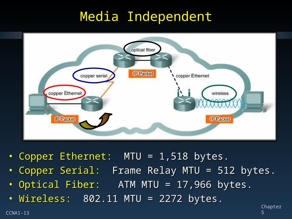
• Copper Ethernet:Copper Ethernet: MTU = 1,518 bytes. MTU = 1,518 bytes.• Copper Serial:Copper Serial: Frame Relay MTU = 512 bytes. Frame Relay MTU = 512 bytes.• Optical Fiber:Optical Fiber: ATM MTU = 17,966 bytes. ATM MTU = 17,966 bytes.• Wireless:Wireless: 802.11 MTU = 2272 bytes. 802.11 MTU = 2272 bytes.
CCNA1-14 Chapter 5
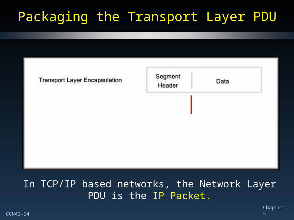
Packaging the Transport Layer PDUPackaging the Transport Layer PDU
In TCP/IP based networks, the Network Layer PDU is the IP Packet.
CCNA1-15 Chapter 5
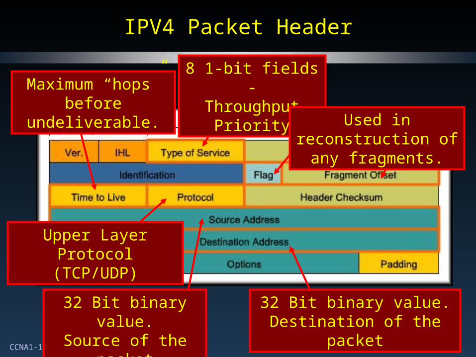
IPV4 Packet HeaderIPV4 Packet Header
32 Bit binary value.Source of the packet
32 Bit binary value.Destination of the packet
Maximum “hops” before undeliverable.
8 1-bit fields -Throughput Priority
Upper Layer Protocol (TCP/UDP)
Used in reconstruction of any fragments.
CCNA1-16 Chapter 5
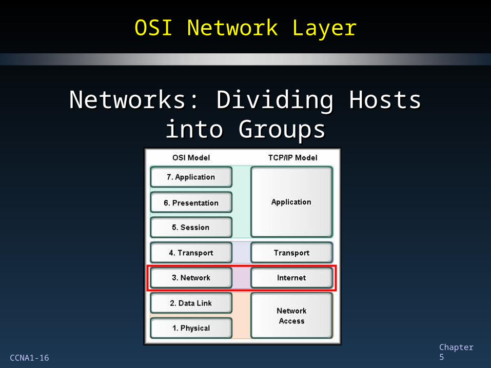
OSI Network LayerOSI Network Layer
Networks: Dividing Hosts into GroupsNetworks: Dividing Hosts into Groups
CCNA1-17 Chapter 5
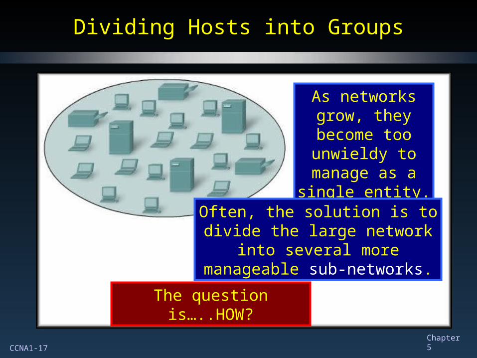
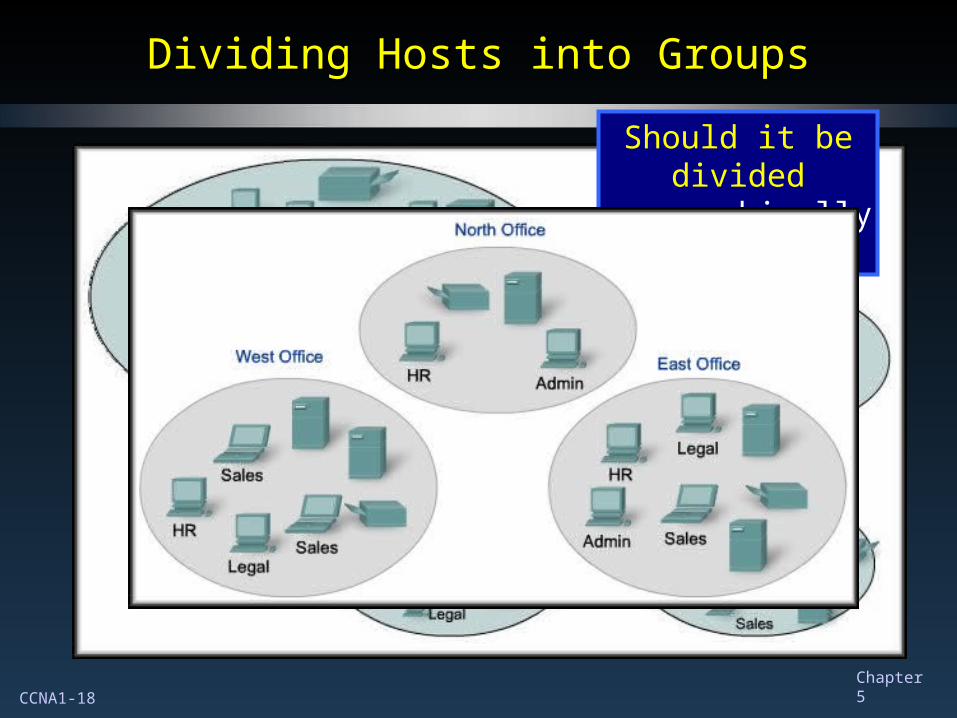
Dividing Hosts into GroupsDividing Hosts into Groups
As networks grow, they become too
unwieldy to manage as a single entity.
Often, the solution is to divide the large network into several more
manageable sub-networks.
The question is…..HOW?
CCNA1-18 Chapter 5
Dividing Hosts into GroupsDividing Hosts into Groups
Should it be divided
geographically?
CCNA1-19 Chapter 5
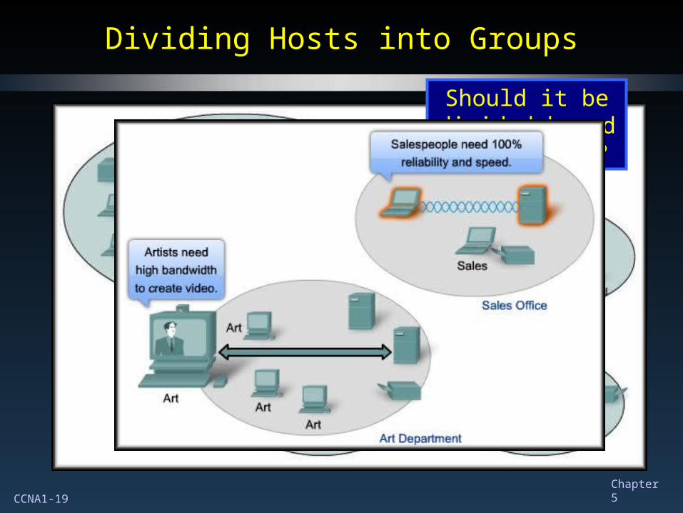
Dividing Hosts into GroupsDividing Hosts into Groups
Should it be divided based on
purpose?
CCNA1-20 Chapter 5
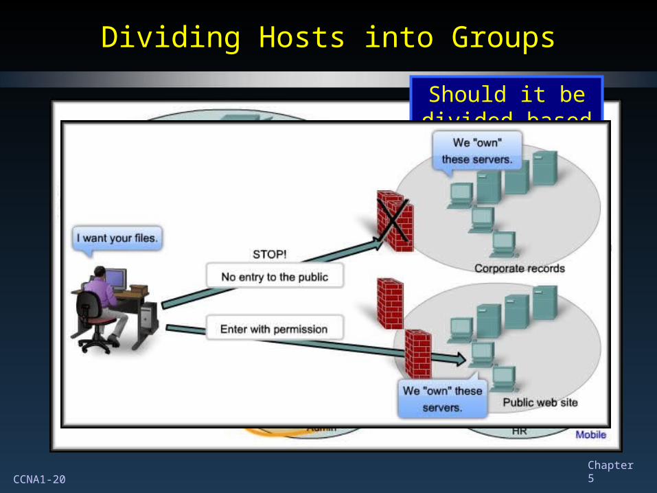
Dividing Hosts into GroupsDividing Hosts into Groups
Should it be divided based on
ownership?
CCNA1-21 Chapter 5
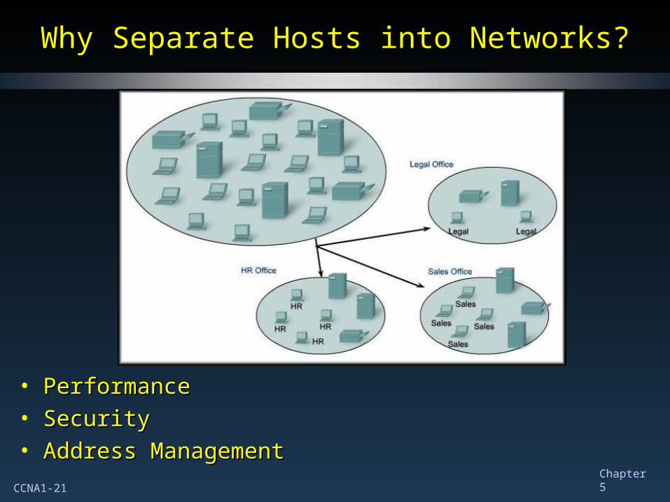
Why Separate Hosts into Networks?Why Separate Hosts into Networks?
• PerformancePerformance• SecuritySecurity• Address ManagementAddress Management
CCNA1-22 Chapter 5
PerformancePerformance
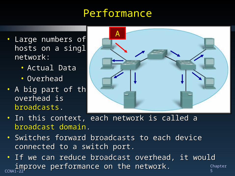
• Large numbers ofLarge numbers ofhosts on a singlehosts on a singlenetwork:network:
• Actual DataActual Data• OverheadOverhead
• A big part of theA big part of theoverhead isoverhead isbroadcastsbroadcasts..
• In this context, each network is called a In this context, each network is called a broadcast domainbroadcast domain..• Switches forward broadcasts to each device connected to a Switches forward broadcasts to each device connected to a
switch port.switch port.• If we can reduce broadcast overhead, it would improve If we can reduce broadcast overhead, it would improve
performance on the network.performance on the network.
A
CCNA1-23 Chapter 5
PerformancePerformance
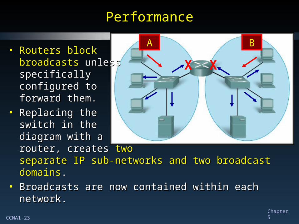
• Routers blockRouters blockbroadcastsbroadcasts unless unlessspecificallyspecificallyconfigured toconfigured toforward them.forward them.
• Replacing theReplacing theswitch in theswitch in thediagram with adiagram with arouter, createsrouter, creates two twoseparate IP sub-networks and two broadcast domainsseparate IP sub-networks and two broadcast domains..
• Broadcasts are now contained within each network. Broadcasts are now contained within each network.
A B
X X
CCNA1-24 Chapter 5
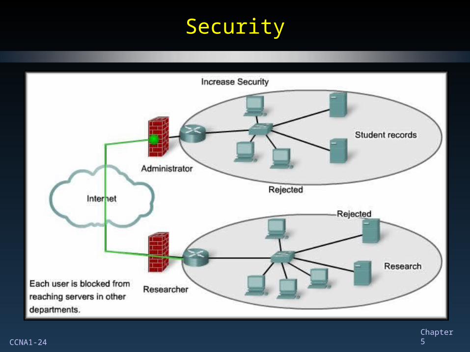
SecuritySecurity
CCNA1-25 Chapter 5
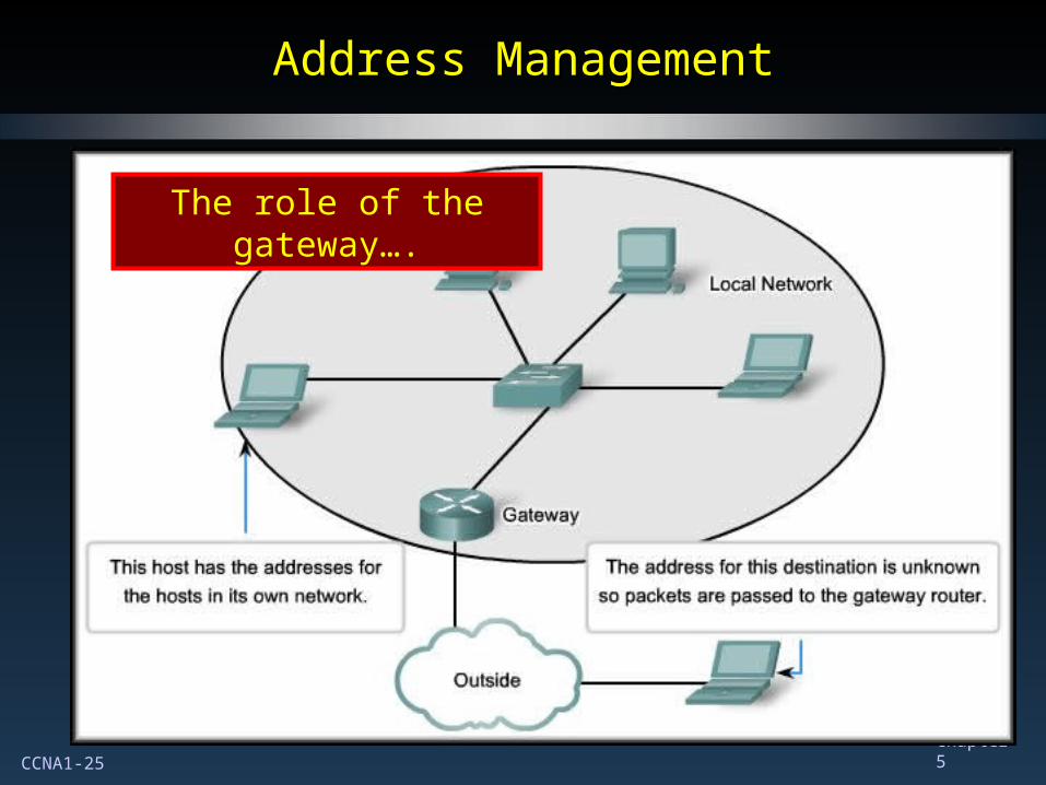
Address ManagementAddress Management
The role of the gateway….
CCNA1-26 Chapter 5
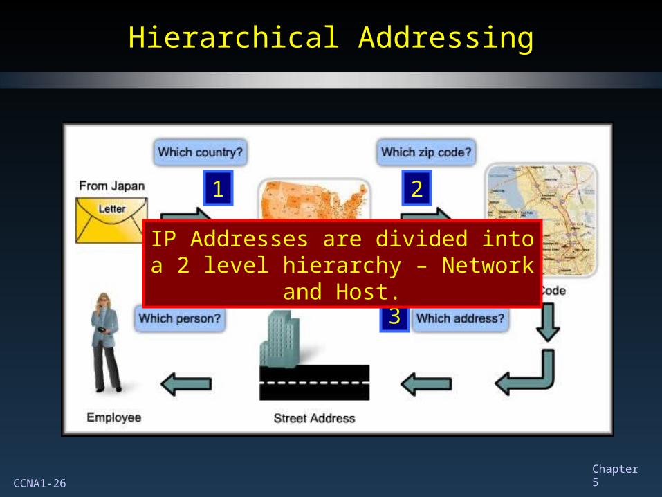
Hierarchical AddressingHierarchical Addressing
1 2
34
IP Addresses are divided into a 2 level hierarchy – Network and Host.
CCNA1-27 Chapter 5
Dividing Networks from NetworksDividing Networks from Networks
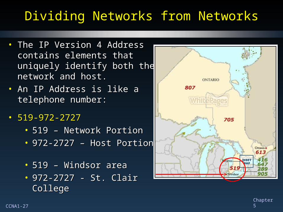
• The IP Version 4 Address The IP Version 4 Address contains elements that uniquely contains elements that uniquely identify both the network and identify both the network and host.host.
• An IP Address is like a An IP Address is like a telephone number:telephone number:
• 519-972-2727519-972-2727• 519 – Network Portion519 – Network Portion• 972-2727 – Host Portion972-2727 – Host Portion
• 519 – Windsor area519 – Windsor area• 972-2727 - St. Clair College972-2727 - St. Clair College
CCNA1-28 Chapter 5
Dividing Networks from NetworksDividing Networks from Networks
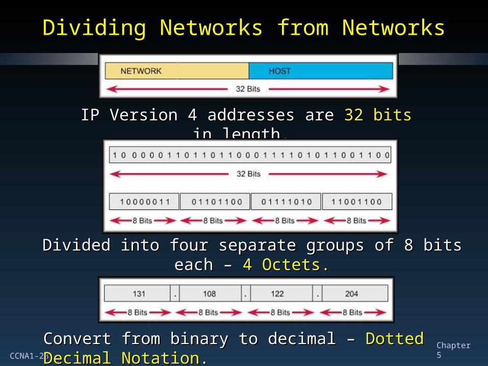
IP Version 4 addresses are IP Version 4 addresses are 32 bits32 bits in length. in length.
Divided into four separate groups of 8 bits each – Divided into four separate groups of 8 bits each – 4 Octets.4 Octets.
Convert from binary to decimal –Convert from binary to decimal – Dotted Decimal Notation Dotted Decimal Notation..
CCNA1-29 Chapter 5
Dividing Networks from NetworksDividing Networks from Networks
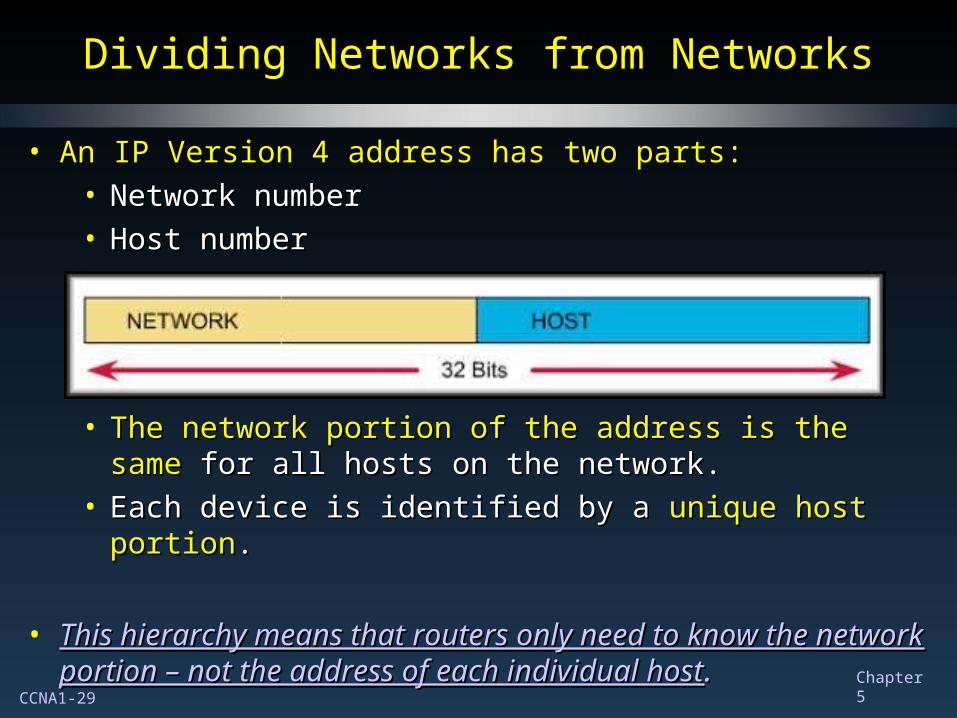
• An IP Version 4 address has two parts:An IP Version 4 address has two parts:• Network numberNetwork number• Host numberHost number
• The network portion of the address is the sameThe network portion of the address is the same for all for all hosts on the network.hosts on the network.
• Each device is identified by a Each device is identified by a unique host portionunique host portion..
• This hierarchy means that routers only need to know the This hierarchy means that routers only need to know the network portion – not the address of each individual hostnetwork portion – not the address of each individual host. .
CCNA1-30 Chapter 5
Dividing Networks from NetworksDividing Networks from Networks
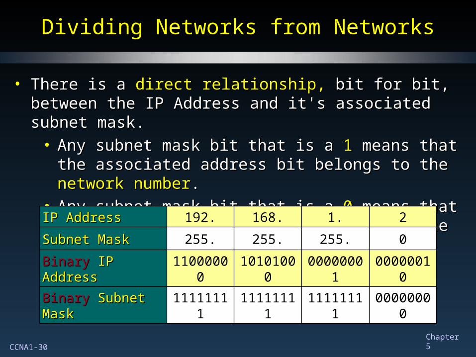
• There is a There is a direct relationship,direct relationship, bit for bit, between the IP bit for bit, between the IP Address and it's associated subnet mask.Address and it's associated subnet mask.
• Any subnet mask bit that is a Any subnet mask bit that is a 11 means that the associated means that the associated address bit belongs to the address bit belongs to the network numbernetwork number..
• Any subnet mask bit that is a Any subnet mask bit that is a 0 0 means that the associated means that the associated address bit belongs to the address bit belongs to the host numberhost number..
IP AddressIP Address 192. 168. 1. 2
Subnet MaskSubnet Mask 255. 255. 255. 0
BinaryBinary IP Address IP Address 11000000 10101000 00000001 00000010
BinaryBinary Subnet Mask Subnet Mask 11111111 11111111 11111111 00000000
CCNA1-31 Chapter 5
IP Addressing – The Subnet MaskIP Addressing – The Subnet Mask
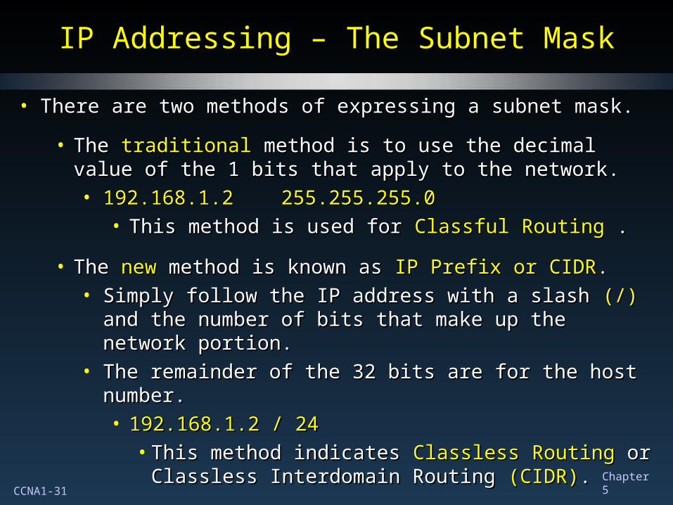
• There are two methods of expressing a subnet mask.There are two methods of expressing a subnet mask.
• The The traditional traditional method is to use the decimal value of the method is to use the decimal value of the 1 bits that apply to the network.1 bits that apply to the network.• 192.168.1.2 255.255.255.0192.168.1.2 255.255.255.0
• This method is used for This method is used for ClassfulClassful RoutingRouting . .
• TheThe new new method is known as method is known as IP Prefix or CIDRIP Prefix or CIDR..• Simply follow the IP address with a slash Simply follow the IP address with a slash (/)(/) and the and the
number of bits that make up the network portion.number of bits that make up the network portion.• The remainder of the 32 bits are for the host number.The remainder of the 32 bits are for the host number.
• 192.168.1.2 / 24192.168.1.2 / 24• This method indicates This method indicates ClasslessClassless Routing Routing or or
Classless Interdomain Routing Classless Interdomain Routing (CIDR)(CIDR)..
CCNA1-32 Chapter 5
IP Addressing – The Subnet MaskIP Addressing – The Subnet Mask
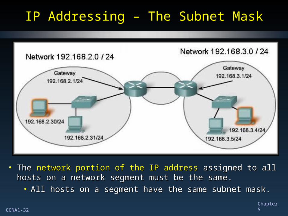
• The The network portion of the IP addressnetwork portion of the IP address assigned to all hosts assigned to all hosts on a network segment must be the same.on a network segment must be the same.
• All hosts on a segment have the same subnet mask.All hosts on a segment have the same subnet mask.
CCNA1-33 Chapter 5
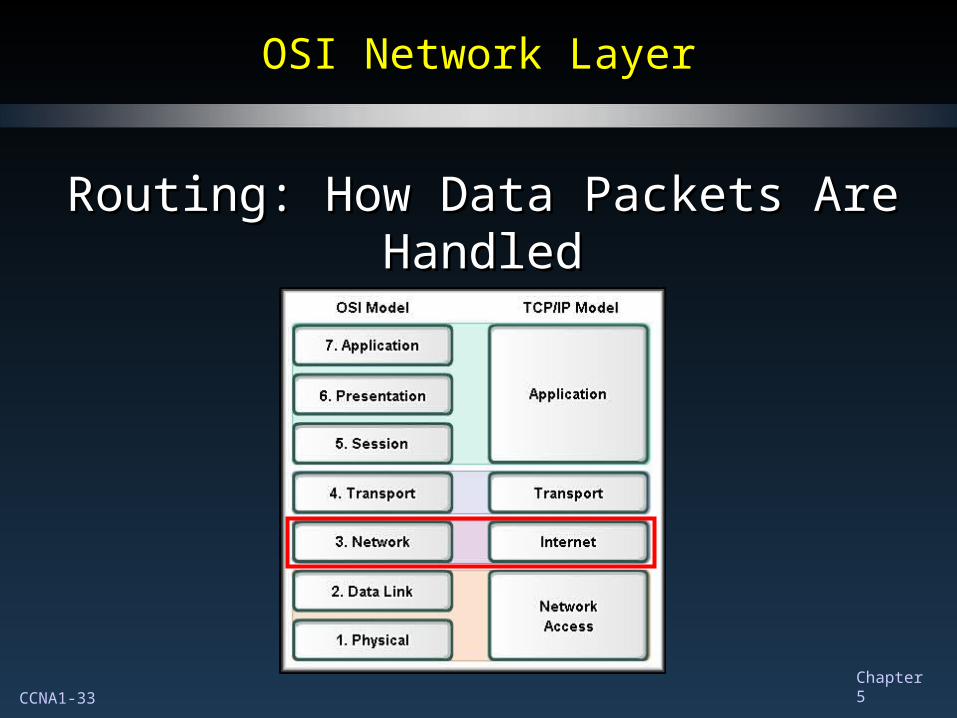
OSI Network LayerOSI Network Layer
Routing: How Data Packets Are HandledRouting: How Data Packets Are Handled
CCNA1-34 Chapter 5
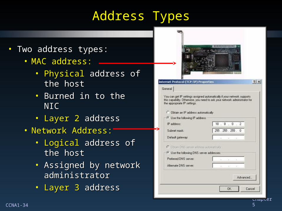
Address TypesAddress Types
• Two address types:Two address types:• MAC address:MAC address:
• PhysicalPhysical address of address of the hostthe host
• Burned in to the NICBurned in to the NIC• Layer 2Layer 2 address address
• Network Address:Network Address:• LogicalLogical address of the address of the
hosthost• Assigned by network Assigned by network
administratoradministrator• Layer 3Layer 3 address address
CCNA1-35 Chapter 5
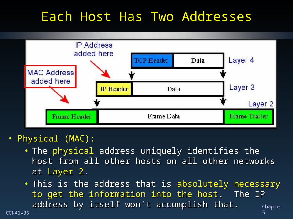
Each Host Has Two AddressesEach Host Has Two Addresses
• Physical (MAC):Physical (MAC):• TheThe physical physical address uniquely identifies the host from all address uniquely identifies the host from all
other hosts on all other networks at other hosts on all other networks at Layer 2Layer 2..• This is the address that is This is the address that is absolutely necessary to get the absolutely necessary to get the
information into the hostinformation into the host. The IP address by itself won't . The IP address by itself won't accomplish that.accomplish that.
CCNA1-36 Chapter 5
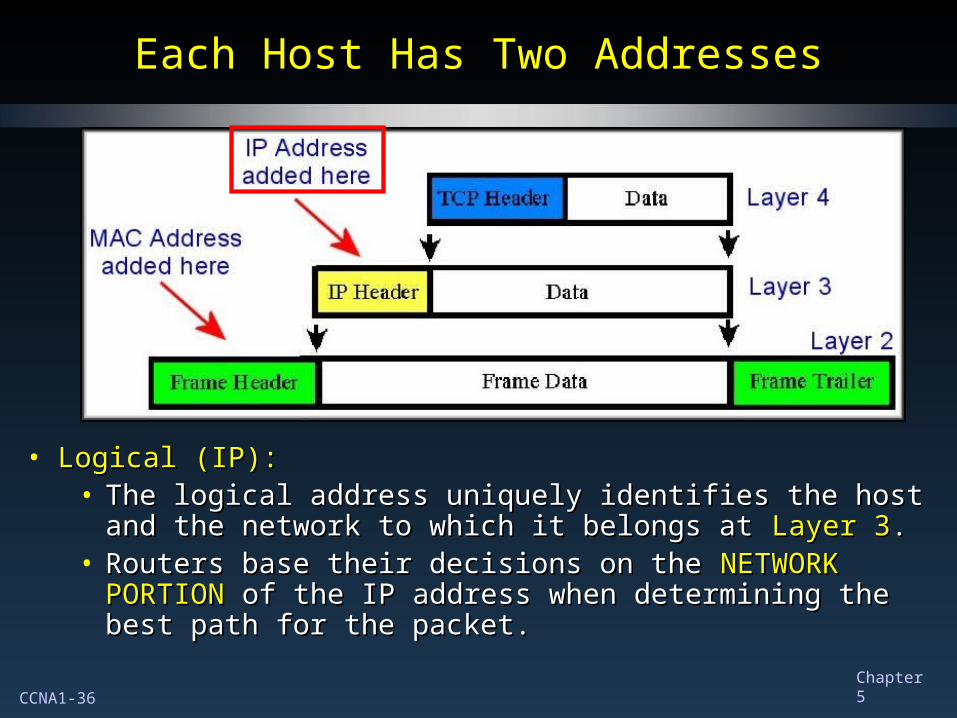
Each Host Has Two AddressesEach Host Has Two Addresses
• Logical (IP):Logical (IP):• The logical address uniquely identifies the host and the The logical address uniquely identifies the host and the
network to which it belongs at network to which it belongs at Layer 3Layer 3..• Routers base their decisions on the Routers base their decisions on the NETWORK NETWORK
PORTIONPORTION of the IP address when determining the best of the IP address when determining the best path for the packet.path for the packet.
CCNA1-37 Chapter 5
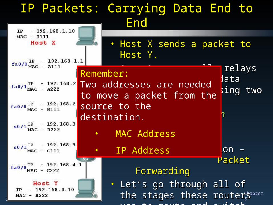
• Host X sends a packet to Host Y.Host X sends a packet to Host Y.• A router generally relays a packet A router generally relays a packet
from one data link to another, using from one data link to another, using two basic functions:two basic functions:
• a a path determinationpath determination function – function –RoutingRouting
• a a switchingswitching function – function –Packet ForwardingPacket Forwarding
• Let’s go through all of the stages Let’s go through all of the stages these routers use to route and these routers use to route and switch this packet.switch this packet.
IP Packets: Carrying Data End to EndIP Packets: Carrying Data End to End
Remember:Two addresses are needed to move a packet from the source to the destination.
• MAC Address
• IP Address

CCNA1-38 Chapter 5
How does Host X know to forward How does Host X know to forward the packet to Router A and not the packet to Router A and not
directly to Host Y?directly to Host Y?
IP Packets: Carrying Data End to EndIP Packets: Carrying Data End to EndLayer 2Layer 2
DestinationDestinationLayer 2Layer 2SourceSource
Layer 3Layer 3DestinationDestination
Layer 3Layer 3SourceSource
A111 H111 192.168.4.10 192.168.1.10
• Host XHost X begins by encapsulating a begins by encapsulating a packet with packet with Host YHost Y’s IP address and ’s IP address and Router ARouter A’s MAC address.’s MAC address.
How does HOST X obtainHow does HOST X obtainRouter A’s Layer 2 address?Router A’s Layer 2 address?
Host X determines that the Host X determines that the destination is destination is NOTNOT on the same on the same
network. (More Later)network. (More Later)The packet is forwarded to the The packet is forwarded to the
default gateway.default gateway.
Queries the router for the router’s Queries the router for the router’s MAC address (more later).MAC address (more later).
CCNA1-39 Chapter 5
NOW what happens?NOW what happens?
IP Packets: Carrying Data End to EndIP Packets: Carrying Data End to EndLayer 2Layer 2
DestinationDestinationLayer 2Layer 2SourceSource
Layer 3Layer 3DestinationDestination
Layer 3Layer 3SourceSource
A111 H111 192.168.4.10 192.168.1.10
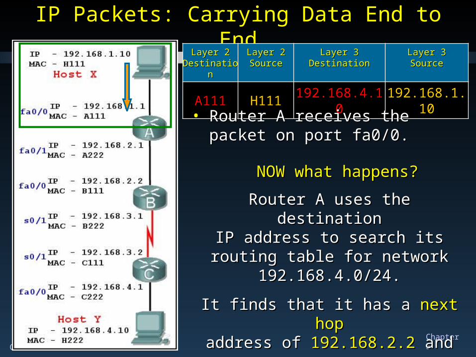
• Router A receives the packet on Router A receives the packet on port fa0/0.port fa0/0.
Router A uses the destinationRouter A uses the destinationIP address to search its routing table IP address to search its routing table
for network 192.168.4.0/24.for network 192.168.4.0/24.
It finds that it has a It finds that it has a next hopnext hopaddress ofaddress of 192.168.2.2 192.168.2.2 and an and an
exit port of exit port of fa0/1.fa0/1.
CCNA1-40 Chapter 5
NOW what happens?NOW what happens?
IP Packets: Carrying Data End to EndIP Packets: Carrying Data End to EndLayer 2Layer 2
DestinationDestinationLayer 2Layer 2SourceSource
Layer 3Layer 3DestinationDestination
Layer 3Layer 3SourceSource
A111 H111 192.168.4.10 192.168.1.10
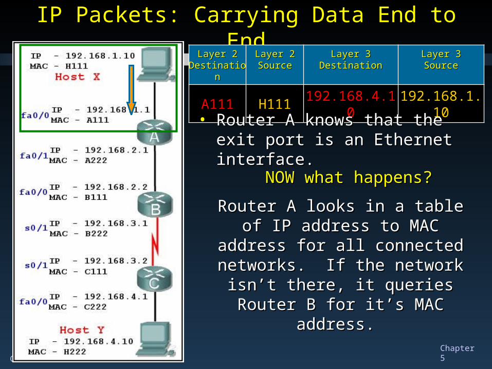
• Router A knows that the exit port is Router A knows that the exit port is an Ethernet interface.an Ethernet interface.
Router A looks in a table of IP Router A looks in a table of IP address to MAC address for all address to MAC address for all
connected networks. If the network connected networks. If the network isn’t there, it queries Router B for it’s isn’t there, it queries Router B for it’s
MAC address. MAC address.
CCNA1-41 Chapter 5
IP Packets: Carrying Data End to EndIP Packets: Carrying Data End to End
192.168.1.10192.168.1.10192.168.4.10192.168.4.10H111H111A111A111
Layer 3Layer 3SourceSource
Layer 3Layer 3DestinationDestination
Layer 2Layer 2SourceSource
Layer 2Layer 2DestinationDestination
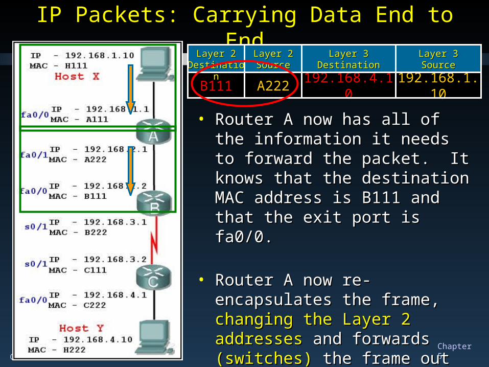
• Router A now has all of the Router A now has all of the information it needs to forward the information it needs to forward the packet. It knows that the packet. It knows that the destination MAC address is B111 destination MAC address is B111 and that the exit port is fa0/0.and that the exit port is fa0/0.
• Router A now re-encapsulates the Router A now re-encapsulates the frame, frame, changing the Layer 2 changing the Layer 2 addresses addresses and forwards and forwards (switches) (switches) the frame out port fa0/1.the frame out port fa0/1.
192.168.1.10192.168.4.10A222B111
Layer 3Layer 3SourceSource
Layer 3Layer 3DestinationDestination
Layer 2Layer 2SourceSource
Layer 2Layer 2DestinationDestination
CCNA1-42 Chapter 5
192.168.1.10192.168.4.10A222B111
Layer 3Layer 3SourceSource
Layer 3Layer 3DestinationDestination
Layer 2Layer 2SourceSource
Layer 2Layer 2DestinationDestination
IP Packets: Carrying Data End to EndIP Packets: Carrying Data End to End
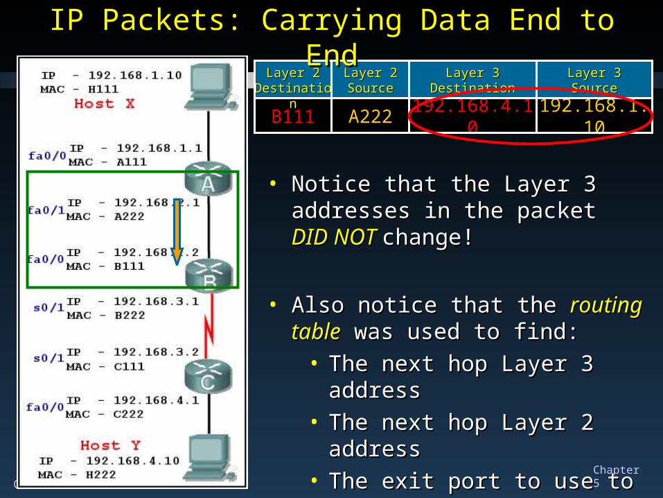
• Notice that the Layer 3 addresses in Notice that the Layer 3 addresses in the packet the packet DID NOT DID NOT change!change!
• Also notice that the Also notice that the routing tablerouting table was used to find:was used to find:
• The next hop Layer 3 addressThe next hop Layer 3 address• The next hop Layer 2 addressThe next hop Layer 2 address• The exit port to use to forward The exit port to use to forward
the frame.the frame.
CCNA1-43 Chapter 5
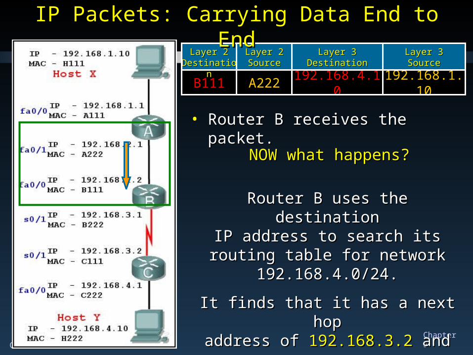
192.168.1.10192.168.4.10A222B111
Layer 3Layer 3SourceSource
Layer 3Layer 3DestinationDestination
Layer 2Layer 2SourceSource
Layer 2Layer 2DestinationDestination
IP Packets: Carrying Data End to EndIP Packets: Carrying Data End to End
• Router B receives the packet.Router B receives the packet.
NOW what happens?NOW what happens?
Router B uses the destinationRouter B uses the destinationIP address to search its routing table IP address to search its routing table
for network 192.168.4.0/24.for network 192.168.4.0/24.
It finds that it has a next hopIt finds that it has a next hopaddress ofaddress of 192.168.3.2 192.168.3.2 and an and an
exit port of exit port of s0/1 – a serial interface.s0/1 – a serial interface.
CCNA1-44 Chapter 5
192.168.1.10192.168.4.10A222B111
Layer 3Layer 3SourceSource
Layer 3Layer 3DestinationDestination
Layer 2Layer 2SourceSource
Layer 2Layer 2DestinationDestination
IP Packets: Carrying Data End to EndIP Packets: Carrying Data End to End
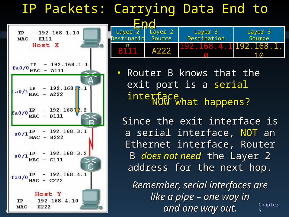
• Router B knows that the exit port is Router B knows that the exit port is a a serial interfaceserial interface..
NOW what happens?NOW what happens?
Since the exit interface is a serial Since the exit interface is a serial interface, interface, NOTNOT an Ethernet interface, an Ethernet interface, Router B Router B does not needdoes not need the Layer 2 the Layer 2
address for the next hop.address for the next hop.
Remember, serial interfaces areRemember, serial interfaces arelike a pipe – one way inlike a pipe – one way in
and one way out.and one way out.
CCNA1-45 Chapter 5
192.168.1.10192.168.4.10A222B111
Layer 3Layer 3SourceSource
Layer 3Layer 3DestinationDestination
Layer 2Layer 2SourceSource
Layer 2Layer 2DestinationDestination
IP Packets: Carrying Data End to EndIP Packets: Carrying Data End to End
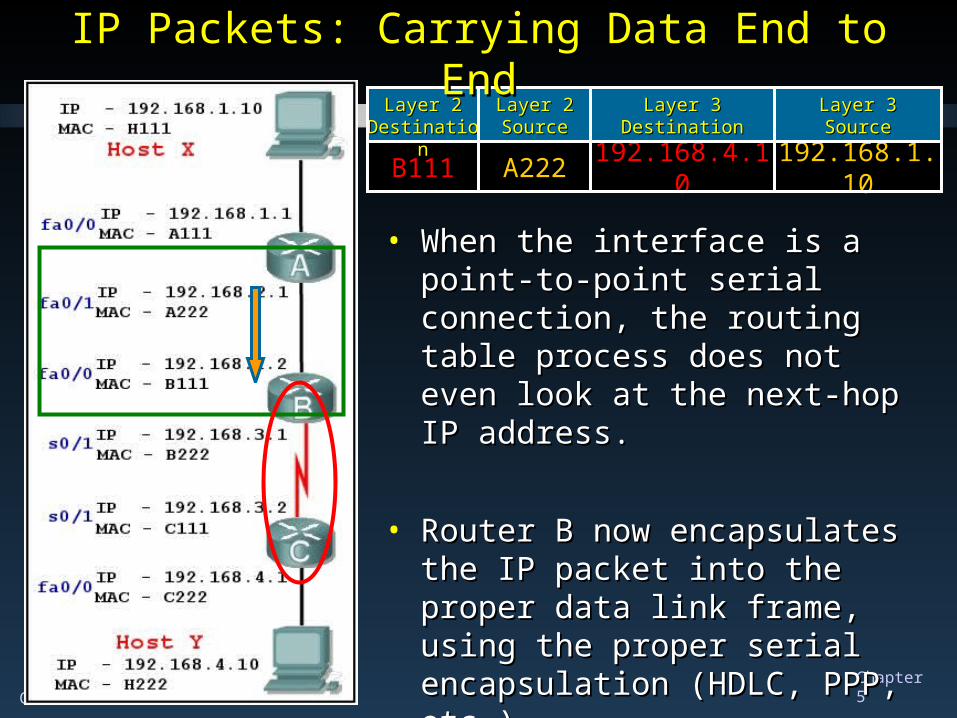
• When the interface is a point-to-When the interface is a point-to-point serial connection, the routing point serial connection, the routing table process does not even look at table process does not even look at the next-hop IP address.the next-hop IP address.
• Router B now encapsulates the IP Router B now encapsulates the IP packet into the proper data link packet into the proper data link frame, using the proper serial frame, using the proper serial encapsulation (HDLC, PPP, etc.).encapsulation (HDLC, PPP, etc.).
CCNA1-46 Chapter 5
192.168.1.10192.168.1.10192.168.4.10192.168.4.10A222A222B111B111
Layer 3Layer 3SourceSource
Layer 3Layer 3DestinationDestination
Layer 2Layer 2SourceSource
Layer 2Layer 2DestinationDestination
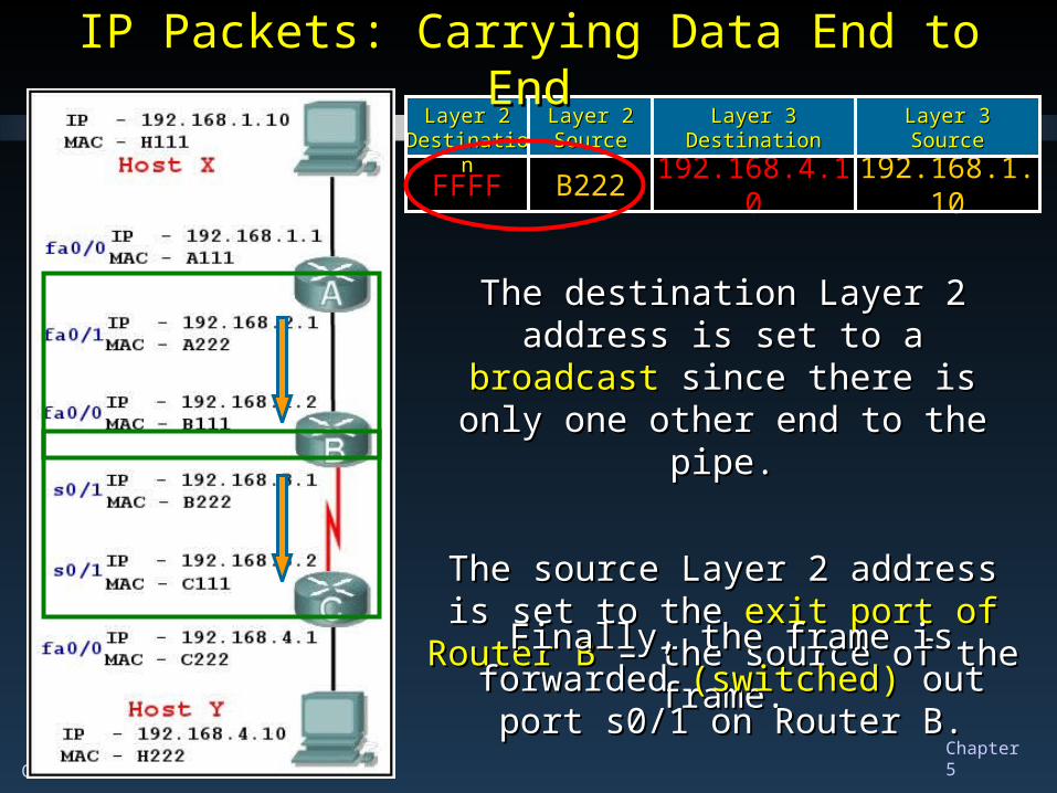
192.168.1.10192.168.4.10B222FFFF
Layer 3Layer 3SourceSource
Layer 3Layer 3DestinationDestination
Layer 2Layer 2SourceSource
Layer 2Layer 2DestinationDestination
IP Packets: Carrying Data End to EndIP Packets: Carrying Data End to End
The destination Layer 2 address is set The destination Layer 2 address is set to a to a broadcast broadcast since there is only one since there is only one
other end to the pipe.other end to the pipe.
The source Layer 2 address is set to The source Layer 2 address is set to the the exit port of Router Bexit port of Router B – the source – the source
of the frame.of the frame.
Finally, the frame is forwarded Finally, the frame is forwarded (switched)(switched) out port s0/1 on Router B. out port s0/1 on Router B.
CCNA1-47 Chapter 5
192.168.1.10192.168.4.10B222FFFF
Layer 3Layer 3SourceSource
Layer 3Layer 3DestinationDestination
Layer 2Layer 2SourceSource
Layer 2Layer 2DestinationDestination
IP Packets: Carrying Data End to EndIP Packets: Carrying Data End to End
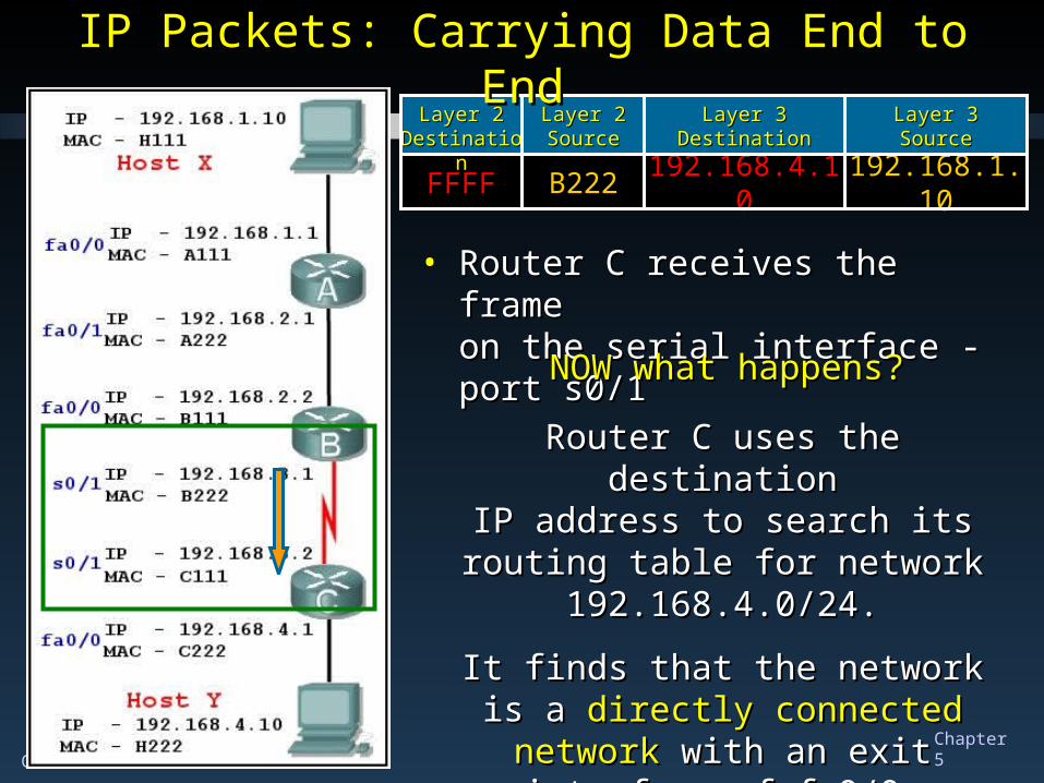
• Router C receives the frameRouter C receives the frameon the serial interface - port s0/1on the serial interface - port s0/1
NOW what happens?NOW what happens?
Router C uses the destinationRouter C uses the destinationIP address to search its routing table IP address to search its routing table
for network 192.168.4.0/24.for network 192.168.4.0/24.
It finds that the network is a It finds that the network is a directly directly connected networkconnected network with an exit with an exit
interface of fa0/0interface of fa0/0..
CCNA1-48 Chapter 5
192.168.1.10192.168.4.10B222FFFF
Layer 3Layer 3SourceSource
Layer 3Layer 3DestinationDestination
Layer 2Layer 2SourceSource
Layer 2Layer 2DestinationDestination
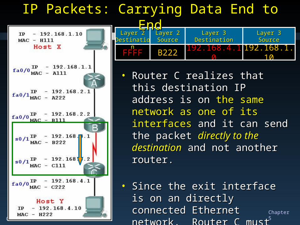
IP Packets: Carrying Data End to EndIP Packets: Carrying Data End to End
• Router C realizes that this Router C realizes that this destination IP address is on destination IP address is on the the same network as one of its same network as one of its interfacesinterfaces and it can send the and it can send the packetpacket directly to the destinationdirectly to the destination and not another router.and not another router.
• Since the exit interface is on an Since the exit interface is on an directly connected Ethernet directly connected Ethernet network, Router C must obtain the network, Router C must obtain the destination’s MAC address.destination’s MAC address.
CCNA1-49 Chapter 5
192.168.1.10192.168.4.10B222FFFF
Layer 3Layer 3SourceSource
Layer 3Layer 3DestinationDestination
Layer 2Layer 2SourceSource
Layer 2Layer 2DestinationDestination
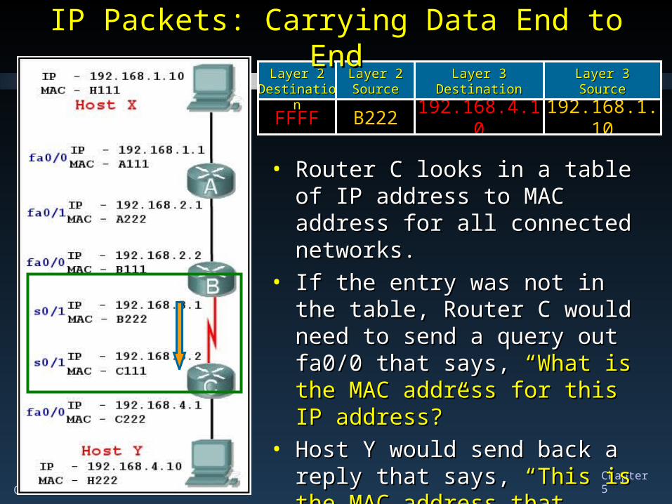
IP Packets: Carrying Data End to EndIP Packets: Carrying Data End to End
• Router C looks in a table of IP Router C looks in a table of IP address to MAC address for all address to MAC address for all connected networks. connected networks.
• If the entry was not in the table, If the entry was not in the table, Router C would need to send a Router C would need to send a query out fa0/0 that says, query out fa0/0 that says, “What is “What is the MAC address for this IP the MAC address for this IP address?”address?”
• Host Y would send back aHost Y would send back a reply that reply that says,says, “This is the MAC address that “This is the MAC address that matches the IP Address you sent.”matches the IP Address you sent.”
CCNA1-50 Chapter 5
192.168.1.10192.168.1.10192.168.4.10192.168.4.10B222B222FFFFFFFF
Layer 3Layer 3SourceSource
Layer 3Layer 3DestinationDestination
Layer 2Layer 2SourceSource
Layer 2Layer 2DestinationDestination
IP Packets: Carrying Data End to EndIP Packets: Carrying Data End to End
192.168.1.10192.168.4.10C222H222
Layer 3Layer 3SourceSource
Layer 3Layer 3DestinationDestination
Layer 2Layer 2SourceSource
Layer 2Layer 2DestinationDestination
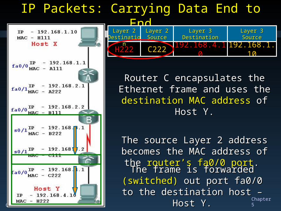
Router C encapsulates the Ethernet Router C encapsulates the Ethernet frame and uses the frame and uses the destination MAC destination MAC
addressaddress of Host Y. of Host Y.
The source Layer 2 address The source Layer 2 address becomes the MAC address of the becomes the MAC address of the
router’s fa0/0 portrouter’s fa0/0 port. .
The frame is forwarded The frame is forwarded (switched) (switched) out port fa0/0 to the destination out port fa0/0 to the destination
host – Host Y.host – Host Y.
CCNA1-51 Chapter 5
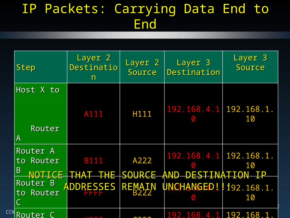
IP Packets: Carrying Data End to EndIP Packets: Carrying Data End to End
StepStep Layer 2 Layer 2 DestinationDestination
Layer 2 Layer 2 SourceSource
Layer 3 Layer 3 DestinationDestination
Layer 3 Layer 3 SourceSource
Host X to Host X to Router A Router A
A111 H111 192.168.4.10 192.168.1.10
Router A to Router A to Router BRouter B
B111 A222 192.168.4.10 192.168.1.10
Router B to Router B to Router CRouter C
FFFF B222 192.168.4.10 192.168.1.10
Router C to Router C to Host YHost Y
H222 C222 192.168.4.10 192.168.1.10
NOTICE THAT THE SOURCE AND DESTINATION IP NOTICE THAT THE SOURCE AND DESTINATION IP ADDRESSES REMAIN UNCHANGED!!!ADDRESSES REMAIN UNCHANGED!!!
CCNA1-52 Chapter 5
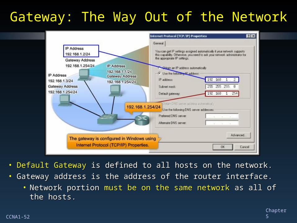
Gateway: The Way Out of the NetworkGateway: The Way Out of the Network
• Default GatewayDefault Gateway is defined to all hosts on the network. is defined to all hosts on the network.• Gateway address is the address of the router interface.Gateway address is the address of the router interface.
• Network portion Network portion must be on the same networkmust be on the same network as all of as all of the hosts.the hosts.
CCNA1-53 Chapter 5
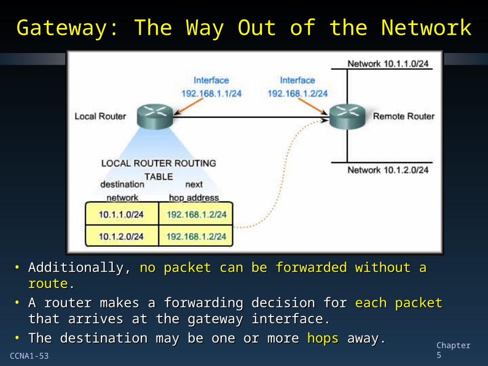
Gateway: The Way Out of the NetworkGateway: The Way Out of the Network
• Additionally, Additionally, no packet can be forwarded without a routeno packet can be forwarded without a route..• A router makes a forwarding decision for A router makes a forwarding decision for each packeteach packet that that
arrives at the gateway interface.arrives at the gateway interface.• The destination may be one or more The destination may be one or more hopshops away. away.
CCNA1-54 Chapter 5
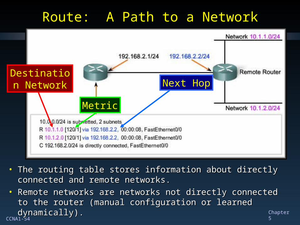
Route: A Path to a NetworkRoute: A Path to a Network
• The routing table stores information about directly connected The routing table stores information about directly connected and remote networks.and remote networks.
• Remote networks are networks not directly connected to the Remote networks are networks not directly connected to the router (manual configuration or learned dynamically).router (manual configuration or learned dynamically).
Destination Network Next Hop
Metric
CCNA1-55 Chapter 5
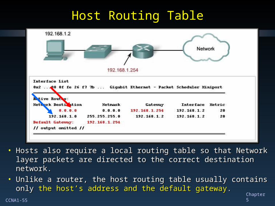
Host Routing TableHost Routing Table
• Hosts also require a local routing table so that Network layer Hosts also require a local routing table so that Network layer packets are directed to the correct destination network. packets are directed to the correct destination network.
• Unlike a router, the host routing table usually contains only Unlike a router, the host routing table usually contains only the host’s address and the default gatewaythe host’s address and the default gateway..
CCNA1-56 Chapter 5
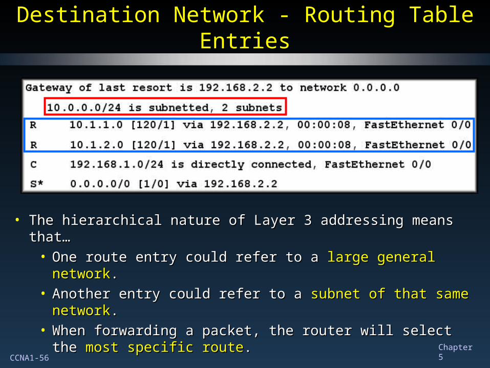
Destination Network - Routing Table EntriesDestination Network - Routing Table Entries
• The hierarchical nature of Layer 3 addressing means that…The hierarchical nature of Layer 3 addressing means that…• One route entry could refer to a One route entry could refer to a large general networklarge general network..• Another entry could refer to a Another entry could refer to a subnet of that same subnet of that same
networknetwork..• When forwarding a packet, the router will select the When forwarding a packet, the router will select the most most
specific routespecific route..
CCNA1-57 Chapter 5
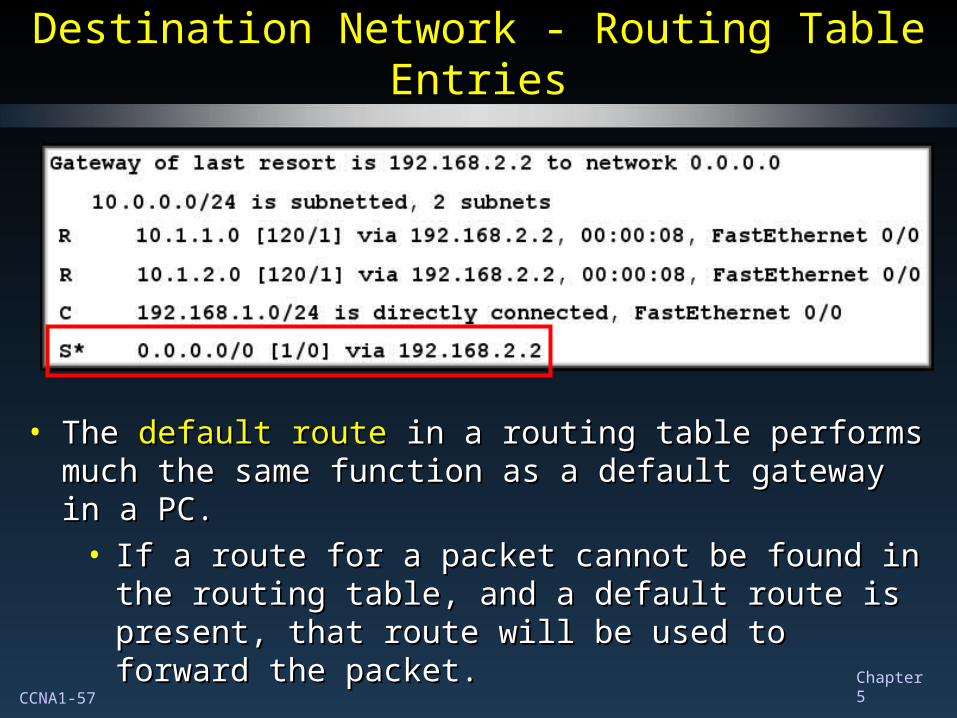
Destination Network - Routing Table EntriesDestination Network - Routing Table Entries
• The The default routedefault route in a routing table performs much the same in a routing table performs much the same function as a default gateway in a PC.function as a default gateway in a PC.
• If a route for a packet cannot be found in the routing If a route for a packet cannot be found in the routing table, and a default route is present, that route will be table, and a default route is present, that route will be used to forward the packet.used to forward the packet.
CCNA1-58 Chapter 5
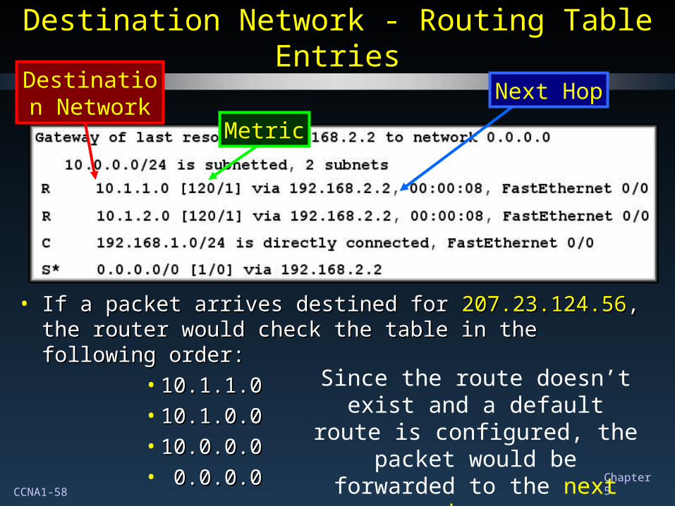
Destination Network - Routing Table EntriesDestination Network - Routing Table Entries
• If a packet arrives destined for If a packet arrives destined for 207.23.124.56207.23.124.56, the router , the router would check the table in the following order:would check the table in the following order:
• 10.1.1.010.1.1.0• 10.1.0.010.1.0.0• 10.0.0.010.0.0.0• 0.0.0.00.0.0.0
Since the route doesn’t exist and a default route is
configured, the packet would be forwarded to the next hop.
Destination Network
Next Hop
Metric
CCNA1-59 Chapter 5
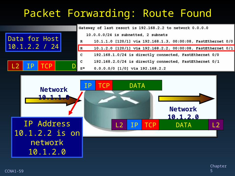
Packet Forwarding: Route FoundPacket Forwarding: Route Found
L2 IP TCP DATA L2
IP TCP DATA
Data for Host 10.1.2.2 / 24
Network 10.1.1.0
Network 10.1.2.0
L2 IP TCP DATA L2IP Address 10.1.2.2 is on
network 10.1.2.0
CCNA1-60 Chapter 5
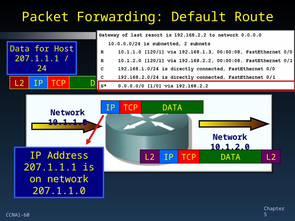
Packet Forwarding: Default RoutePacket Forwarding: Default Route
L2 IP TCP DATA L2
IP TCP DATA
Data for Host 207.1.1.1 / 24
Network 10.1.1.0
Network 10.1.2.0
L2 IP TCP DATA L2IP Address 207.1.1.1 is on
network 207.1.1.0
CCNA1-61 Chapter 5
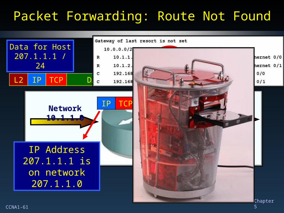
Packet Forwarding: Route Not FoundPacket Forwarding: Route Not Found
L2 IP TCP DATA L2
IP TCP DATA
Data for Host 207.1.1.1 / 24
Network 10.1.1.0
Network 10.1.2.0
IP Address 207.1.1.1 is on
network 207.1.1.0
??
CCNA1-62 Chapter 5
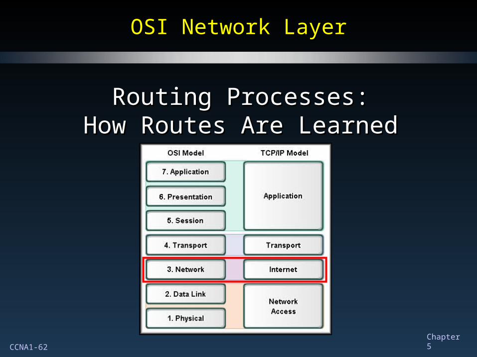
OSI Network LayerOSI Network Layer
Routing Processes:Routing Processes:How Routes Are LearnedHow Routes Are Learned
CCNA1-63 Chapter 5
Routing Processes: How Routes Are LearnedRouting Processes: How Routes Are Learned
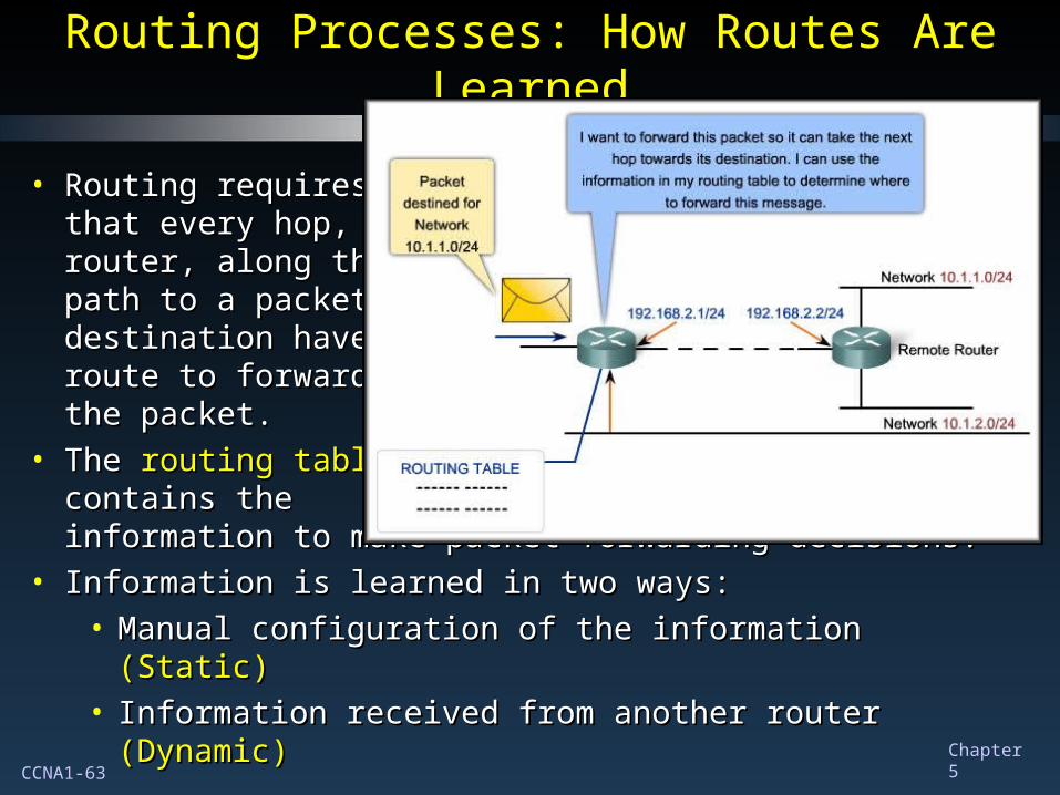
• Routing requiresRouting requiresthat every hop, orthat every hop, orrouter, along therouter, along thepath to a packet'spath to a packet'sdestination have adestination have aroute to forwardroute to forwardthe packet.the packet.
• The The routing tablerouting tablecontains thecontains theinformation to make packet forwarding decisions.information to make packet forwarding decisions.
• Information is learned in two ways:Information is learned in two ways:• Manual configuration of the information Manual configuration of the information (Static)(Static)• Information received from another router Information received from another router (Dynamic)(Dynamic)
CCNA1-64 Chapter 5
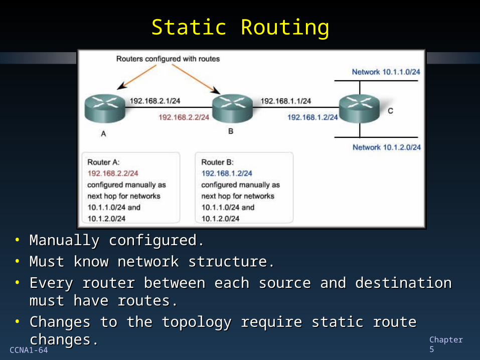
Static RoutingStatic Routing
• Manually configured.Manually configured.• Must know network structure.Must know network structure.• Every router between each source and destination must have Every router between each source and destination must have
routes.routes.• Changes to the topology require static route changes.Changes to the topology require static route changes.
CCNA1-65 Chapter 5
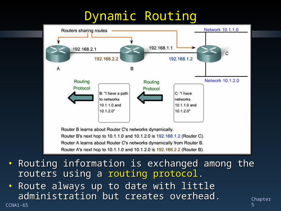
Dynamic RoutingDynamic Routing
• Routing information is exchanged among the routers using a Routing information is exchanged among the routers using a routing protocolrouting protocol..
• Route always up to date with little administration but creates Route always up to date with little administration but creates overhead.overhead.
CCNA1-66 Chapter 5
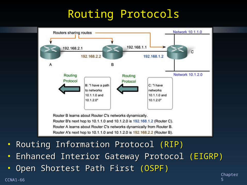
Routing ProtocolsRouting Protocols
• Routing Information Protocol Routing Information Protocol (RIP)(RIP)• Enhanced Interior Gateway Protocol Enhanced Interior Gateway Protocol (EIGRP)(EIGRP)• Open Shortest Path First Open Shortest Path First (OSPF)(OSPF)
CCNA1-67 Chapter 5