catv balun ii (500302) application guide - muxlab...
TRANSCRIPT
CATV Balun II Application Guide
©MuxLab Inc. 2007-2010 1
CATV Balun II (500302)
Application GuideVersion 1.05
Oct 2010
CATV Balun II Application Guide
©MuxLab Inc. 2007-2010 2
IntroductionBroadband CATV has experienced a steady growth in recent years due to theintroduction of digital cable and broadband Internet services. Coupled with this growthhas been the need to streamline the cabling infrastructure to support the proliferation ofnewly installed equipment. MuxLab’s CATV Balun II (500302), with its improvedbandwidth performance is helping to widen the range of broadband services that aresupported by copper twisted pair and RF video technology.
PurposeThis document is a sequel to the CATV Balun II Application Guide and its purpose is toexplain the enhanced performance and capabilities of the CATV Balun II. The documentis meant to supplement the CATV Balun II Installation Guide and not to replace it.
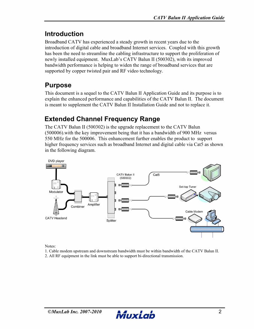
Extended Channel Frequency RangeThe CATV Balun II (500302) is the upgrade replacement to the CATV Balun(500006).with the key improvement being that it has a bandwidth of 900 MHz versus550 MHz for the 500006. This enhancement further enables the product to supporthigher frequency services such as broadband Internet and digital cable via Cat5 as shownin the following diagram.
Notes:1. Cable modem upstream and downstream bandwidth must be within bandwidth of the CATV Balun II.2. All RF equipment in the link must be able to support bi-directional transmission.
CATV Balun II Application Guide
©MuxLab Inc. 2007-2010 3
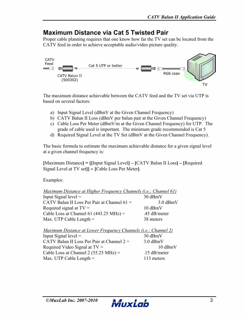
Maximum Distance via Cat 5 Twisted PairProper cable planning requires that one know how far the TV set can be located from theCATV feed in order to achieve acceptable audio/video picture quality.
The maximum distance achievable between the CATV feed and the TV set via UTP isbased on several factors:
a) Input Signal Level (dBmV at the Given Channel Frequency)b) CATV Balun II Loss (dBmV per balun pair at the Given Channel Frequency)c) Cable Loss Per Meter (dBmV/m at the Given Channel Frequency) for UTP. The
grade of cable used is important. The minimum grade recommended is Cat 5d) Required Signal Level at the TV Set (dBmV at the Given Channel Frequency).
The basic formula to estimate the maximum achievable distance for a given signal levelat a given channel frequency is:
[Maximum Distance] = [[Input Signal Level] – [CATV Balun II Loss] – [RequiredSignal Level at TV set]] ÷ [Cable Loss Per Meter].
Examples:
Maximum Distance at Higher Frequency Channels (i.e.; Channel 61)Input Signal level = 30 dBmVCATV Balun II Loss Per Pair at Channel 61 = 3.0 dBmVRequired signal at TV = 10 dBmVCable Loss at Channel 61 (445.25 MHz) = .45 dB/meterMax. UTP Cable Length = 38 meters
Maximum Distance at Lower Frequency Channels (i.e.; Channel 2)Input Signal level = 30 dBmVCATV Balun II Loss Per Pair at Channel 2 = 3.0 dBmVRequired Video Signal at TV = 10 dBmVCable Loss at Channel 2 (55.25 MHz) = .15 dB/meterMax. UTP Cable Length = 113 meters
CATV Balun II Application Guide
©MuxLab Inc. 2007-2010 4
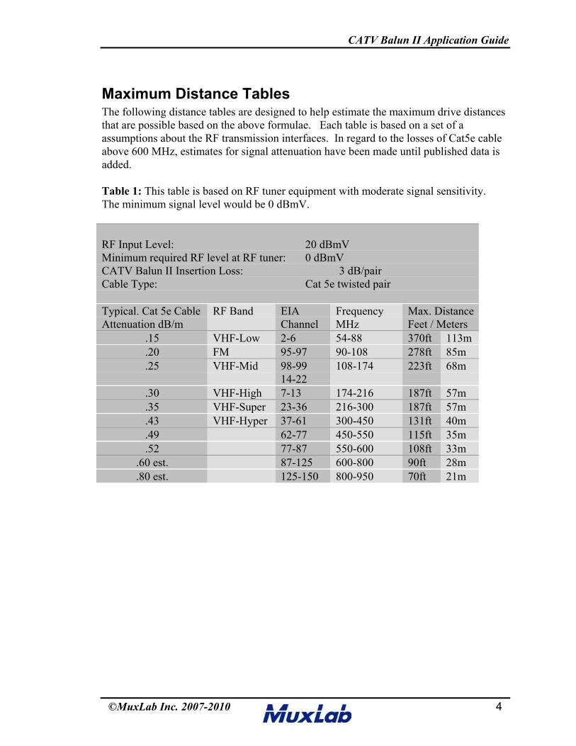
Maximum Distance TablesThe following distance tables are designed to help estimate the maximum drive distancesthat are possible based on the above formulae. Each table is based on a set of aassumptions about the RF transmission interfaces. In regard to the losses of Cat5e cableabove 600 MHz, estimates for signal attenuation have been made until published data isadded.
Table 1: This table is based on RF tuner equipment with moderate signal sensitivity.The minimum signal level would be 0 dBmV.
RF Input Level: 20 dBmVMinimum required RF level at RF tuner: 0 dBmVCATV Balun II Insertion Loss: 3 dB/pairCable Type: Cat 5e twisted pair
Typical. Cat 5e CableAttenuation dB/m
RF Band EIAChannel
FrequencyMHz
Max. DistanceFeet / Meters
.15 VHF-Low 2-6 54-88 370ft 113m
.20 FM 95-97 90-108 278ft 85m
.25 VHF-Mid 98-9914-22
108-174 223ft 68m
.30 VHF-High 7-13 174-216 187ft 57m
.35 VHF-Super 23-36 216-300 187ft 57m
.43 VHF-Hyper 37-61 300-450 131ft 40m
.49 62-77 450-550 115ft 35m
.52 77-87 550-600 108ft 33m.60 est. 87-125 600-800 90ft 28m.80 est. 125-150 800-950 70ft 21m
CATV Balun II Application Guide
©MuxLab Inc. 2007-2010 5
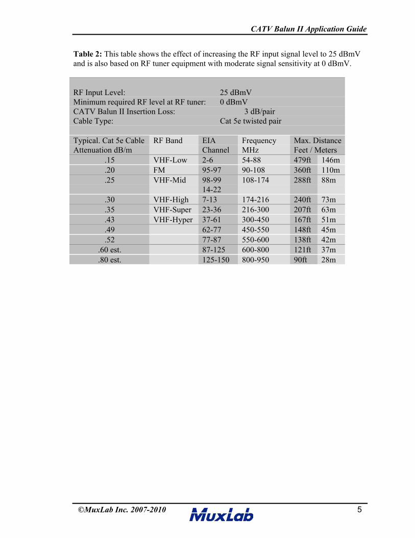
Table 2: This table shows the effect of increasing the RF input signal level to 25 dBmVand is also based on RF tuner equipment with moderate signal sensitivity at 0 dBmV.
RF Input Level: 25 dBmVMinimum required RF level at RF tuner: 0 dBmVCATV Balun II Insertion Loss: 3 dB/pairCable Type: Cat 5e twisted pair
Typical. Cat 5e CableAttenuation dB/m
RF Band EIAChannel
FrequencyMHz
Max. DistanceFeet / Meters
.15 VHF-Low 2-6 54-88 479ft 146m
.20 FM 95-97 90-108 360ft 110m
.25 VHF-Mid 98-9914-22
108-174 288ft 88m
.30 VHF-High 7-13 174-216 240ft 73m
.35 VHF-Super 23-36 216-300 207ft 63m
.43 VHF-Hyper 37-61 300-450 167ft 51m
.49 62-77 450-550 148ft 45m
.52 77-87 550-600 138ft 42m.60 est. 87-125 600-800 121ft 37m.80 est. 125-150 800-950 90ft 28m
CATV Balun II Application Guide
©MuxLab Inc. 2007-2010 6
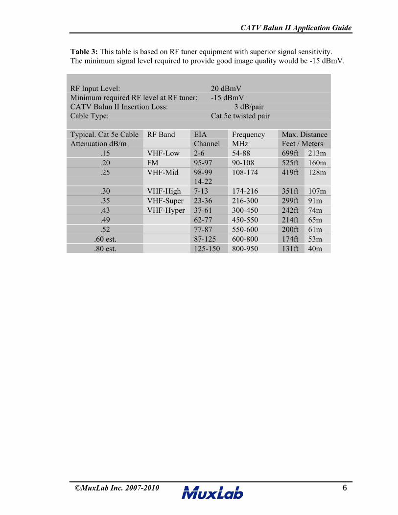
Table 3: This table is based on RF tuner equipment with superior signal sensitivity.The minimum signal level required to provide good image quality would be -15 dBmV.
RF Input Level: 20 dBmVMinimum required RF level at RF tuner: -15 dBmVCATV Balun II Insertion Loss: 3 dB/pairCable Type: Cat 5e twisted pair
Typical. Cat 5e CableAttenuation dB/m
RF Band EIAChannel
FrequencyMHz
Max. DistanceFeet / Meters
.15 VHF-Low 2-6 54-88 699ft 213m
.20 FM 95-97 90-108 525ft 160m
.25 VHF-Mid 98-9914-22
108-174 419ft 128m
.30 VHF-High 7-13 174-216 351ft 107m
.35 VHF-Super 23-36 216-300 299ft 91m
.43 VHF-Hyper 37-61 300-450 242ft 74m
.49 62-77 450-550 214ft 65m
.52 77-87 550-600 200ft 61m.60 est. 87-125 600-800 174ft 53m.80 est. 125-150 800-950 131ft 40m
CATV Balun II Application Guide
©MuxLab Inc. 2007-2010 7
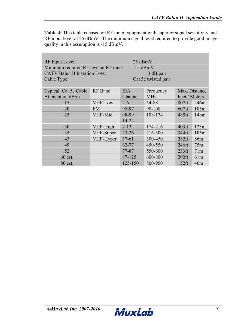
Table 4: This table is based on RF tuner equipment with superior signal sensitivity andRF input level of 25 dBmV. The minimum signal level required to provide good imagequality in this assumption is -15 dBmV.
RF Input Level: 25 dBmVMinimum required RF level at RF tuner: -15 dBmVCATV Balun II Insertion Loss: 3 dB/pairCable Type: Cat 5e twisted pair
Typical. Cat 5e CableAttenuation dB/m
RF Band EIAChannel
FrequencyMHz
Max. DistanceFeet / Meters
.15 VHF-Low 2-6 54-88 807ft 246m
.20 FM 95-97 90-108 607ft 185m
.25 VHF-Mid 98-9914-22
108-174 485ft 148m
.30 VHF-High 7-13 174-216 403ft 123m
.35 VHF-Super 23-36 216-300 344ft 105m
.43 VHF-Hyper 37-61 300-450 282ft 86m
.49 62-77 450-550 246ft 75m
.52 77-87 550-600 233ft 71m.60 est. 87-125 600-800 200ft 61m.80 est. 125-150 800-950 152ft 46m
CATV Balun II Application Guide
©MuxLab Inc. 2007-2010 8
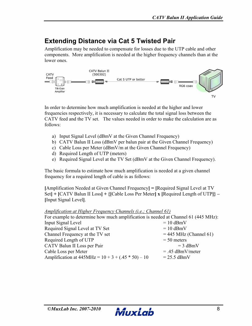
Extending Distance via Cat 5 Twisted PairAmplification may be needed to compensate for losses due to the UTP cable and othercomponents. More amplification is needed at the higher frequency channels than at thelower ones.
In order to determine how much amplification is needed at the higher and lowerfrequencies respectively, it is necessary to calculate the total signal loss between theCATV feed and the TV set. The values needed in order to make the calculation are asfollows:
a) Input Signal Level (dBmV at the Given Channel Frequency)b) CATV Balun II Loss (dBmV per balun pair at the Given Channel Frequency)c) Cable Loss per Meter (dBmV/m at the Given Channel Frequency)d) Required Length of UTP (meters)e) Required Signal Level at the TV Set (dBmV at the Given Channel Frequency).
The basic formula to estimate how much amplification is needed at a given channelfrequency for a required length of cable is as follows:
[Amplification Needed at Given Channel Frequency] = [Required Signal Level at TVSet] + [CATV Balun II Loss] + {[Cable Loss Per Meter] x [Required Length of UTP]} –[Input Signal Level].
Amplification at Higher Frequency Channels (i.e.; Channel 61)For example to determine how much amplification is needed at Channel 61 (445 MHz):Input Signal Level = 10 dBmVRequired Signal Level at TV Set = 10 dBmVChannel Frequency at the TV set = 445 MHz (Channel 61)Required Length of UTP = 50 metersCATV Balun II Loss per Pair = 3 dBmVCable Loss per Meter = .45 dBmV/meterAmplification at 445MHz = 10 + 3 + (.45 * 50) – 10 = 25.5 dBmV
CATV Balun II Application Guide
©MuxLab Inc. 2007-2010 9
Amplification at Lower Frequency Channels (i.e.; Channel 2)For example to determine how much amplification is needed at Channel 2 (55.25MHz):Input Signal Level = 10 dBmVRequired Signal Level at TV Set = 10 dBmVChannel Frequency at the TV set = 55.25 MHz (Channel 2)Required Length of UTP = 50 metersCATV Balun II Loss per Pair = 3 dBmVCable Loss Per meter = .15 dBmV/meterAmplification at 55.25 MHz = 10 + 3 + (.15 x 50) – 10 = 10.5 dBmV
Once the required amplification at the high and low frequencies are determined, theamount of amplifier “tilt” can be determined. Based on the two calculations above, theamount of “tilt” needed is:
Tilt = Amplification at High Frequency – Amplification at Low Frequency = 28.5 dBmV – 10.5 dBmV = 18 dBmV
Therefore the amplifier in this case should provide 25.5 dBmV amplification at 445MHzwith a tilt of 18 dBmV over the frequency range. Some amplifiers have fixed tilt-gain.Others have adjustable tilt-gain. In the example above, one could use an amplifieroperating in the 40MHz -1GHz range that provides a gain of up to 35 dBmV with a tiltcontrol of up to 20 dBmV.
RF Splitters
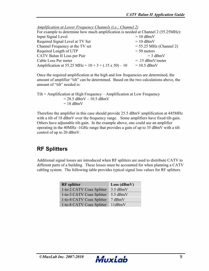
Additional signal losses are introduced when RF splitters are used to distribute CATV todifferent parts of a building. These losses must be accounted for when planning a CATVcabling system. The following table provides typical signal loss values for RF splitters.
RF splitter Loss (dBmV)1-to-2 CATV Coax Splitter 3.5 dBmV1-to-3 CATV Coax Splitter 5.5 dBmV1-to-4 CATV Coax Splitter 7 dBmV1-to-8 CATV Coax Splitter 11dBmV
CATV Balun II Application Guide
©MuxLab Inc. 2007-2010 10
Cable ModemsCable modems allow Internet, telephony and CATV services to be offered via theexisting CATV cabling infrastructure. The ability to support cable modem service viaUTP depends on the performance of the CATV balun that converts the CATV coax cableto UTP. MuxLab’s CATV Balun II has an operating frequency of 5MHz to 950 MHz.Cable modem applications are supported via UTP providing the following conditions aremet:
1. The downstream data channel lies within the operating frequency range of the CATVbalun.
2. The upstream data channel lies within the operating frequency range of the CATVbalun.
3. All data channels are able to tolerate the added signal loss introduced by the balunsand UTP.
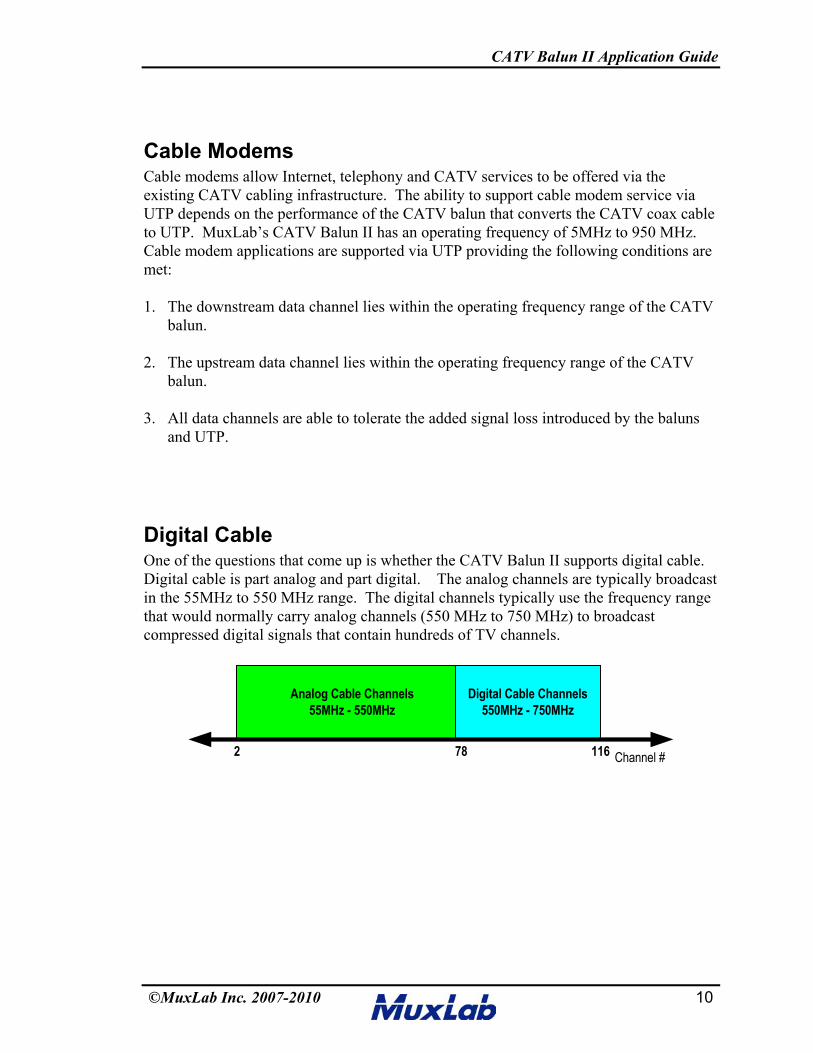
Digital CableOne of the questions that come up is whether the CATV Balun II supports digital cable.Digital cable is part analog and part digital. The analog channels are typically broadcastin the 55MHz to 550 MHz range. The digital channels typically use the frequency rangethat would normally carry analog channels (550 MHz to 750 MHz) to broadcastcompressed digital signals that contain hundreds of TV channels.
Channel #
Analog Cable Channels55MHz - 550MHz
Digital Cable Channels550MHz - 750MHz
2 78 116
CATV Balun II Application Guide
©MuxLab Inc. 2007-2010 11
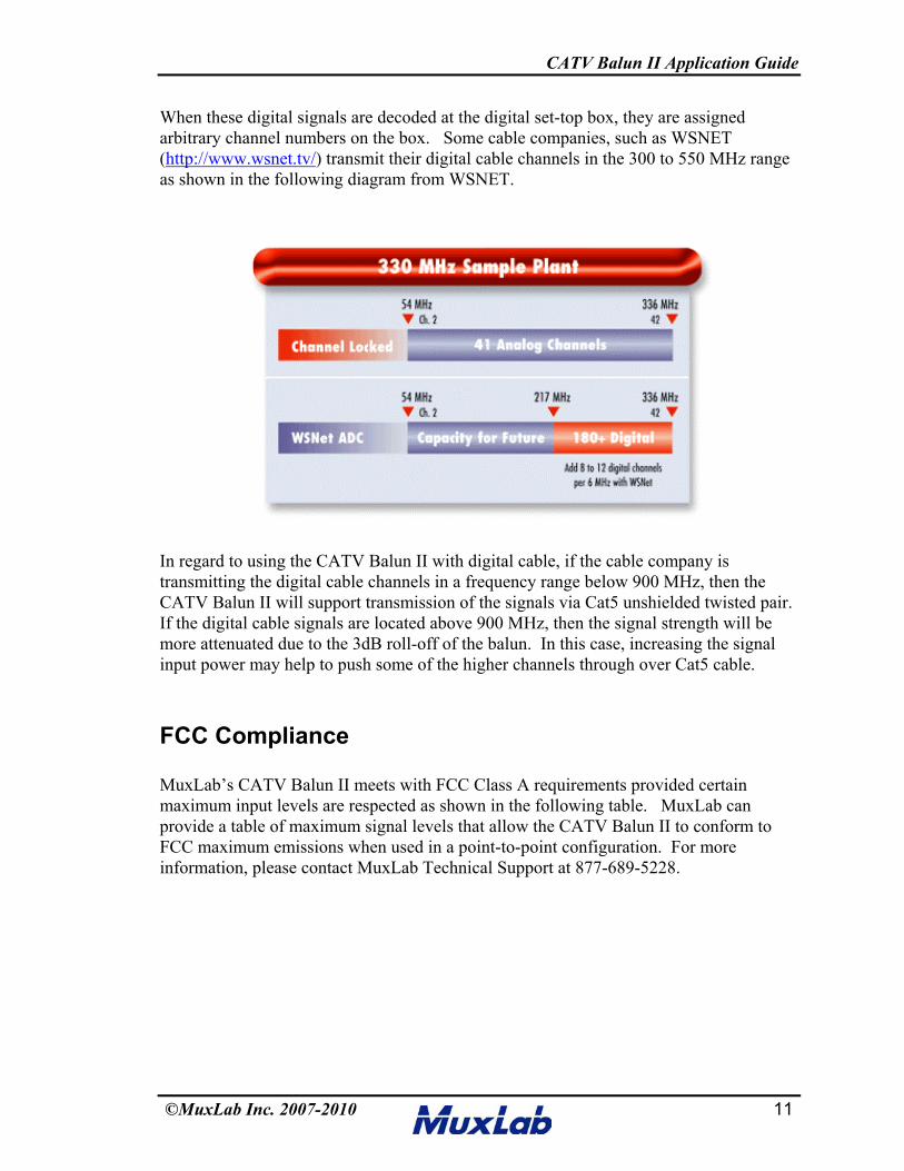
When these digital signals are decoded at the digital set-top box, they are assignedarbitrary channel numbers on the box. Some cable companies, such as WSNET(http://www.wsnet.tv/) transmit their digital cable channels in the 300 to 550 MHz rangeas shown in the following diagram from WSNET.
In regard to using the CATV Balun II with digital cable, if the cable company istransmitting the digital cable channels in a frequency range below 900 MHz, then theCATV Balun II will support transmission of the signals via Cat5 unshielded twisted pair.If the digital cable signals are located above 900 MHz, then the signal strength will bemore attenuated due to the 3dB roll-off of the balun. In this case, increasing the signalinput power may help to push some of the higher channels through over Cat5 cable.
FCC Compliance
MuxLab’s CATV Balun II meets with FCC Class A requirements provided certainmaximum input levels are respected as shown in the following table. MuxLab canprovide a table of maximum signal levels that allow the CATV Balun II to conform toFCC maximum emissions when used in a point-to-point configuration. For moreinformation, please contact MuxLab Technical Support at 877-689-5228.
CATV Balun II Application Guide
©MuxLab Inc. 2007-2010 12
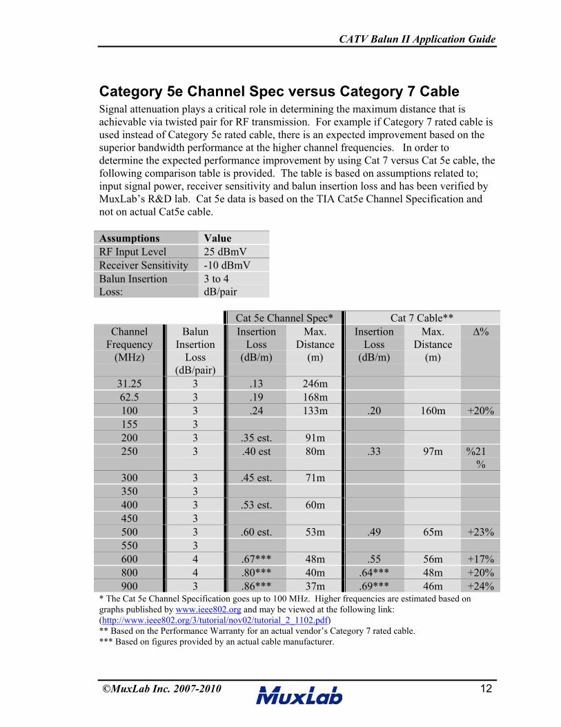
Category 5e Channel Spec versus Category 7 CableSignal attenuation plays a critical role in determining the maximum distance that isachievable via twisted pair for RF transmission. For example if Category 7 rated cable isused instead of Category 5e rated cable, there is an expected improvement based on thesuperior bandwidth performance at the higher channel frequencies. In order todetermine the expected performance improvement by using Cat 7 versus Cat 5e cable, thefollowing comparison table is provided. The table is based on assumptions related to;input signal power, receiver sensitivity and balun insertion loss and has been verified byMuxLab’s R&D lab. Cat 5e data is based on the TIA Cat5e Channel Specification andnot on actual Cat5e cable.
Assumptions ValueRF Input Level 25 dBmVReceiver Sensitivity -10 dBmVBalun InsertionLoss:
3 to 4dB/pair
Cat 5e Channel Spec* Cat 7 Cable**Channel
Frequency(MHz)
BalunInsertion
Loss(dB/pair)
InsertionLoss
(dB/m)
Max.Distance
(m)
InsertionLoss
(dB/m)
Max.Distance
(m)
∆%
31.25 3 .13 246m62.5 3 .19 168m100 3 .24 133m .20 160m +20%155 3200 3 .35 est. 91m250 3 .40 est 80m .33 97m %21
%300 3 .45 est. 71m350 3400 3 .53 est. 60m450 3500 3 .60 est. 53m .49 65m +23%550 3600 4 .67*** 48m .55 56m +17%800 4 .80*** 40m .64*** 48m +20%900 3 .86*** 37m .69*** 46m +24%
* The Cat 5e Channel Specification goes up to 100 MHz. Higher frequencies are estimated based ongraphs published by www.ieee802.org and may be viewed at the following link:(http://www.ieee802.org/3/tutorial/nov02/tutorial_2_1102.pdf)** Based on the Performance Warranty for an actual vendor’s Category 7 rated cable.*** Based on figures provided by an actual cable manufacturer.
CATV Balun II Application Guide
©MuxLab Inc. 2007-2010 13
Doubling Up Twisted PairsIn regard to the CATV Balun II and based on testing by MuxLab’s R&D dept, there isperformance degradation if the twisted pairs are doubled up. In the lab, it was found thatthere was 55% more signal loss versus no doubling. The lower performance is mainlydue to impedance mismatch since the doubled twisted pairs present a 50-ohm impedanceto the balun instead of 100 ohms. The test was performed using a 200 ft length ofCategory 5e UTP cable and a second Cat5e cable with pins 7&8 "doubled up". Theresult was approximately 6.8 dB (55%) more signal loss than if there was no doubling-up. Consequently it is not recommended to double-up twisted pairs when using theCATV Balun II in the RF environment.
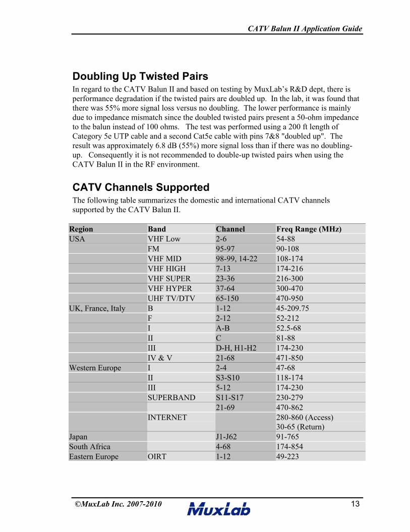
CATV Channels SupportedThe following table summarizes the domestic and international CATV channelssupported by the CATV Balun II.
Region Band Channel Freq Range (MHz)USA VHF Low 2-6 54-88
FM 95-97 90-108VHF MID 98-99, 14-22 108-174VHF HIGH 7-13 174-216VHF SUPER 23-36 216-300VHF HYPER 37-64 300-470UHF TV/DTV 65-150 470-950
UK, France, Italy B 1-12 45-209.75F 2-12 52-212I A-B 52.5-68II C 81-88III D-H, H1-H2 174-230IV & V 21-68 471-850
Western Europe I 2-4 47-68II S3-S10 118-174III 5-12 174-230SUPERBAND S11-S17 230-279
21-69 470-862INTERNET 280-860 (Access)
30-65 (Return)Japan J1-J62 91-765South Africa 4-68 174-854Eastern Europe OIRT 1-12 49-223
CATV Balun II Application Guide
©MuxLab Inc. 2007-2010 14
Cabling Guidelines – What to Plan For1. When planning and installing a CATV system using UTP, the following guidelines
are suggested -
2. Use Cat 5 UTP cable or better and make sure there are no splices or kinks in thecables.
3. Keep cabling away from sources of electromagnetic interference such as fluorescentlights, transformers, radio transmitters, and power cables.
4. In order to minimize the effects of crosstalk, install home-run cables from the CATVdistribution panel to each TV set.
5. Keep UTP cable distances within the CATV balun vendor’s specifications.
6. In order to minimize electromagnetic interference (EMI), when terminating thetwisted pairs, ensure that the twisted pairs remain twisted right up to the point oftermination. Do not use UTP splits or taps.
7. Before installing equipment, test the video image quality of the longest cable run.
8. On cable runs where the signal may overdrive TV set use attenuators. Based onindustry specifications, no more than 10 dBmV should be at the TV set.
9. If the system needs to be amplified install amplifiers as far “upstream” as possible.For example, place one amplifier at the head-end and one tilt-gain amplifier in eachwiring closet where the baluns are located.
10. Try for 10dBmV of signal strength at each television. When in doubt, run the signala little high to the television and use an attenuator to lower the signal strength goinginto the TV. Attenuators may be combined (i.e. two -3dBmV attenuators will equal -6dBmV). According to industry experts, many TV sets operate below 0dBmV(1mV).
11. For downstream only applications, ensure that all splitters, taps, and amplifiers arerated for operation from 50MHz to 860MHz or more. If upstream communicationsare also needed, ensure all splitters and taps are rated for operation from 5MHz to860MHz or more. In addition, all amplifiers must be either rated for downstreamoperation from 50MHz to 860MHz or more and upstream/reversal operation from5MHz to 42MHz, or have external upstream filtering added as necessary.
12. Check and make sure that all televisions are ready to receive the desired channelfrequencies.
CATV Balun II Application Guide
©MuxLab Inc. 2007-2010 15
13. Always compensate for insertion loss with a good amplifier. There will always be adrop in signal strength when combining a modulator to an existing system due toinsertion loss from the combiner.
14. When combining an existing signal with a modulated signal, make sure to have equalsignal strength at the point of the combiner so one signal does not degrade the other.
15. For channels outside the supported frequencies, use a channel converter to place thechannel on a carrier that is within a frequency band supported by the cabling. Whenpossible, use the lowest frequencies available for the modulated channels in order toachieve maximum distance. If channels are available, allow 1 to 2 channel spacingbetween “modulated” and "active" channels.
16. If using modulators, install them as close to the head-end as possible.
17. The maximum input signal that can be transmitted through the CATV Balun II is60dBmV.
Compatibility with the 500006The CATV Balun II (500302) and CATV Hub (500300, 500301, 500303, 500304) arefully compatible with the CATV Balun (500006) and may be mixed and matched in thesame installation. However, when the 500006 is installed on one end and the 500302 or500300 is installed on the opposite end, the performance specifications are in accordancewith the 500006.

CATV Balun II Application Guide
©MuxLab Inc. 2007-2010 16
RF AmplifiersIn order to compensate for signal losses, it may be necessary to use an RF amplifier. Dueto the fact that the higher channel frequencies exhbit higher losses than the lowerchannels, it is advisable to use an RF amplifier that has a “tilt” or “slope” adjustment,such as from Channel Vision (CVT-40BID), Triax (TLA 240E) and Toner Cable(TDA35-1000).
CVT-40BID (USA) TDA35-1000 (UK)
http://www.ambientweather.com/dbcvt40bid.html http://www.tonercable.com/index.php?id=3&ProdID=413
TLA 240E (UK)http://www.triax.com/AntennaSystems/Distr/Amplifiers/Distribution%20amplifiers/RF%20+%20SAT%20amplifiers.aspx?productId=
{BE026723-D39D-4A11-8FE6-FA92D9482E28}&Tab=0
Ground Loop IsolatorsGround loop problems can result when the signal ground of the CATV cable is at adifferent voltage level than the CATV receiver in the building. The image may displayhorizontal bands moving up the screen and an audible “hum” may be present. In order toisolate the ground, it is recommended to use a CATV RF ground loop isolator such theones shown in the photo below.
CATV Balun II Application Guide
©MuxLab Inc. 2007-2010 17
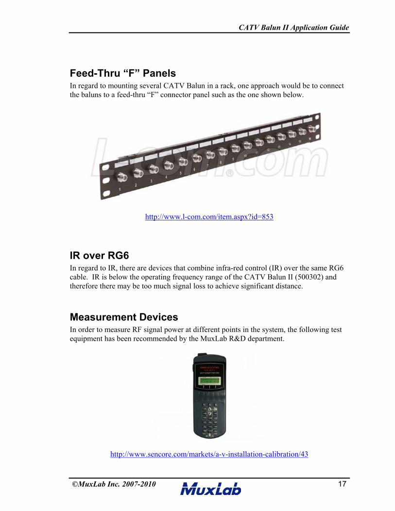
Feed-Thru “F” PanelsIn regard to mounting several CATV Balun in a rack, one approach would be to connectthe baluns to a feed-thru “F” connector panel such as the one shown below.
http://www.l-com.com/item.aspx?id=853
IR over RG6In regard to IR, there are devices that combine infra-red control (IR) over the same RG6cable. IR is below the operating frequency range of the CATV Balun II (500302) andtherefore there may be too much signal loss to achieve significant distance.
Measurement DevicesIn order to measure RF signal power at different points in the system, the following testequipment has been recommended by the MuxLab R&D department.
http://www.sencore.com/markets/a-v-installation-calibration/43

CATV Balun II Application Guide
©MuxLab Inc. 2007-2010 18
Off Air InterferenceIn some cases, off air channels may interfere with the CATV channels coming in fromthe CATV provider. This may be caused by nearby broadcasting stations. Theinterference is often manifest by multiple lines running through the screen as shown inthe images below. In order to correct the problem, it is recommended to add an RFamplifier upstream from the source balun. This has been validated in MuxLab’sfacilities.
Z-Band and 500302According to feedback from a customer, they tested the 500302 with the Z-Band CATVHub in a single ended configuration and found it worked satisfactorily. However,MuxLab has not tested the configuration and therefore cannot guarantee performance.
CATV Balun II Application Guide
©MuxLab Inc. 2007-2010 19
ConclusionStructured cabling techniques, when applied to CATV can be an effective way to offerbroadband video and Internet services more easily to greater number of viewers in aschool, office or home environment. However, structured CATV cabling via coppertwisted pair requires more planning and pre-testing than other cabling systems. For moreinformation, contact an expert in the design and installation of broadband video systems.
CATV Balun II Application Guide
©MuxLab Inc. 2007-2010 20
Glossary
Adjacent Channels - Any of two TV channels are considered adjacent when theirfrequencies are next to each other in frequency or channel number.
Amplifier - A device that boosts the strength of a television signal.
Analog - A method of signal transmission in which information is relayed bycontinuously altering the wave form of the electromagnetic current. Now used in AMradio or most voice telephone circuits. In telephone transmission, the signal beingtransmitted voice, video or image is "analogous" to the original signal.
Antenna - A wireless system component that converts wired electrical energy to wirelessradio waves, and directs them through the air in some pattern.
Attenuation - In general terms, a reduction in signal strength.
Automatic Gain Control - A circuit for automatically controlling amplifier gain in orderto maintain a constant output voltage with a varying input voltage within a predeterminedrange of input-to-output variation. A process by which gain is automatically adjusted as afunction of input or other specified parameter.
Band - A clearly defined range of radio frequencies dedicated to a particular purpose.
Bandwidth - The number of cycles per second (Hertz) expressing the difference betweenthe lower and upper limiting frequencies of a frequency band; also, the width of a band offrequencies. The range of frequencies within which the performance of the antenna, withrespect to some characteristic, conforms to a specified standard. Greater bandwidthgenerally provides for a more robust system because changes in the installationenvironment will not degrade antenna performance.
Bandwidth - A range of frequencies on the electromagnetic spectrum.
Bi-directional - Communications between two points where each point both transmitsand receives.
Broadband - A descriptive term for evolving digital technologies that provideconsumers a signal switched facility offering integrated access to voice, high-speed dataservice, video-on-demand services and interactive delivery services.
Broadband - In television system use, a device having a bandpass greater than the bandof a single VHF television channel.
CATV Balun II Application Guide
©MuxLab Inc. 2007-2010 21
CATV Cable TV - A service through which subscribers pay to have local televisionstations and other programs brought into their homes from the antenna via coaxial cable
Cable Modem - A modem that connects to a cable TV network, providing Internetaccess, typically for homes with speeds comparable to DSL. The download speed isgenerally higher than the upload speed, but since cable connections are shared, the actualspeed varies, depending on the number of users attached to the network.
Coax - Short for coaxial cable.
Coaxial Cable - A type of cable capable of transmitting a range of frequencies with lowsignal loss. Commonly used for transmitting video and audio in security systems.
Coaxial Cable - A type of cable commonly used in cable (CATV) and direct broadcastsatellite (DBS) television systems. Composed of two concentric conductors (an innerwire and a braided shield) separated by a dielectric material. The whole thing is usuallywrapped in another insulating layer and an outer protective layer. Most coaxial cableused in CATV and DBS applications has an impedance of 75 ohms. A coaxial cable hasgreat capacity to carry great quantities of information. It is typically used to carry high-speed data and in CATV (multiplexed TV stations.)
Crosstalk - An undesired signal from a different channel interfering with the desiredsignal.
dB - Decibels A technique for expressing voltage, power, gain, loss, or frequency inlogarithmic form against a reference. Typical references include volts, Watts or Ohms.An analog unit of measure of signal strength, volume or signal loss due to resistance asexpressed in logarithmic form. A measure of the power ratio of two signals. In systemuse, a measure of the voltage ratio of two signals, provided they are measured across acommon impedance.
Hz. - Decibels are calculated using the expression: dB = 10*log(x/y)
dBmV - A signal measurement whereby 0 dBmV equals 1000 microvolts across 75ohms. A recommended signal level for a TV to receive is 10 dBmV.
Decibel - A unit to measure the relative levels of current, voltage or power. This is thescale used to measure the strength of a TV signal. An increase of 3 dB indicates adoubling of power.
Demodulation - The process for retrieving an information signal that has beenmodulated onto a carrier.
Descrambler - Set-top box. A device which corrects a signal (often video) that has beenintentionally distorted to prevent unauthorized viewing. Used with satellite TV systems.
CATV Balun II Application Guide
©MuxLab Inc. 2007-2010 22
Digital - A method of storing, converting and sending data in the form of binary digits ( 0or 1). In displays, the use of digits for direct readout. In telecommunications, in therecording or in computing, digital is the use of a binary code to represent information.Analog signals (like voice or music) are encoded digitally by sampling the voice or musicanalog signals many times a second and assigning a number to each sample. Recording ortransmitting information digitally has two major benefits. The signal can be reproducedmore precisely so digital transmission is much "cleaner" than analog transmission. Thesecond major benefit of digital is that the electronic circuitry to handle digital is gettingcheaper and more powerful.
Digital Cable - Digital cable is a term for a type of cable digital television that deliversmore channels than possible with analog cable by using digital video compression.Digital cable also enables two-way communication, enabling services such the ability topurchase pay-per-view programming without the use of a phone line. Recently, somecompanies have also added video on demand services.
Distortion - The deviation of the received signal waveform from that of the originaltransmitted waveform.
Distribution Amplifier - A device that provides several isolated outputs from onelooping or bridging input, and has a sufficiently high input impedance and input-to-output isolation to prevent loading of the input source.
Dynamic Range - The difference between the maximum acceptable signal level and theminimum acceptable signal level.
F-connector - The final piece of hardware on a cable designed for CATV or DBS orother signal distribution applications. It is cylindrical with a center pin sticking out, thatplugs into the set-top box, cable ready TV, satellite receiver, or VCR.
Filter - A circuit that selects the frequency of desired channels through the use of bandpass, low pass, and high pass filters remove certain unwanted signals to make room forthe insertion of a new modulated TV channel
Frequency Response - The range of band of frequencies to which a unit of electronicequipment will offer essentially the same characteristics.
Frequency - The number of times an electromagnetic wave goes through a completecycle in one second, measured in Hertz.
Gain - An increase in voltage or power, usually expressed in dB. In a given direction, 4pi times the ratio of the radiation intensity in that direction to the net power accepted bythe antenna from the connected transmitter. A measure of amplification expressed in dB.Gain of an amplifier is usually specified at the highest frequency of operation.
CATV Balun II Application Guide
©MuxLab Inc. 2007-2010 23
Ghost - A spurious image resulting from an echo.
GHz - Gigahertz; one trillion cycles per second (a measure of frequency).
Headend - A cable TV systems control center where incoming signals from satellites andother sources are put into the system. (Head End) The originating point of a signal incable TV systems. At the head end, you'll often find large satellite receiving antennae. Acentral control device required within some LAN systems to provide such centralizedfunctions as demodulation, re-timing, message accountability, connection control,diagnostic control, and access.
Headend Homerun Wire - The Homerun Wire is most often a single wire (usually anRG6 or RG59 coaxial cable) that runs from each apartment building's meter room to eachapartment and is designed to deliver television or telephone services. Some of the modernday Homerun Wires are being used to deliver all services, cable and satellite television,telephone and fax and high-speed Internet connections.
High Definition Television - Technology that significantly increases the resolution ofdigital video signals offering vastly improved picture quality over the current NTSCstandard.
Hum - Electrical disturbance at the power supply frequency or harmonics thereof.
Hz - Hertz Cycle per second; a measure of electromagnetic frequency that represents thenumber of complete electrical waves in a second. One kilohertz (kHz) is one thousandcycles per second; one megahertz (MHz) is one million; one gigahertz (GHz) is onebillion.Impedance (input or output) The input or output characteristic of a system componentthat determines the type of transmission cable to be used. The cable used must have thesame characteristic impedance as the component. Expressed in ohms. Video distributionhas standardized on 75-ohm coaxial and 124-ohm balanced cable.
Inside Wiring - That wiring located inside your premises or building. Inside wiring startsat the telephone or cable company's Demarcation Point and extends to the individualextensions. Traditionally, Inside Wiring was installed and owned by the installingcompany.
Interference - Extraneous energy which tends to interfere with the reception of thedesired signals.
Jitter - Small, rapid variations in a waveform due to mechanical disturbances or tochanges in the characteristic of components. Supply voltages, imperfect synchronizingsignals, circuits, etc.
CATV Balun II Application Guide
©MuxLab Inc. 2007-2010 24
Line Amplifier - An amplifier for audio or video signals that feeds a transmission line;also called program amplifier.
Loop Through - Also called looping. The method of feeding a series of high impedancecircuits (such as multiple monitor/displays in parallel) from a pulse or video source witha coax transmission line in such a manner that the line is bridged (with minimum lengthstubs) and that the last unit properly terminates the line in its characteristic impedance.This minimizes discontinuities or reflections on the transmission line.
Loss - A reduction in signal level or strength, usually expressed in dB. Power dissipationserving no useful purpose.
Low-Frequency Distortion - Distortion effects which occur at low frequencies. Intelevision, generally considered as any frequency below the 15.75 kHz line frequency.
Matrix Switcher - A device that routes any of its inputs to any of its outputs. Inputs arenormally cameras or alarms, and outputs are normally recorders or monitors. A matrixswitcher allows a user to control what information is sent where within a large securitynetwork.
MHz - Megahertz, a measure of frequency in millions (mega) of cycles per second.
MMDS - Multipoint Multi-channel Distribution Service. MMDS is a way of distributingcable television signals, through microwave, from a single transmission point to multiplereceiving points. Often used as an alternative to cable-bases cable TV. An MMDSservice, "in digital form, will provide more than 100 channels to a radius ofapproximately 40 miles from the transmitter. The MMDS transmitter delivers video tohomes that are in its 'line of sight.' MMDS transmissions are limited by the terrain andfoliage of a given market. The microwave signal is received by an antenna on thesubscriber's home, then sent down coaxial cable to a box atop the customer's TV set. Thebox decodes and decompresses the digital signal." MMDS is increasingly being called"Wireless Cable."
Modems - Acronym for Modulator/Demodulator. Conventional modems compriseequipment which converts digital signals to analog signals and vice versa. ConventionalPC modems outputs data in the form of "1's" and "0's" which are represented by varyinglevels of voltage. The modem converts the digital data signal into variations of the analogsine wave so the data can be transmitted over the device with a digital bit stream. Themodulation techniques include some combination of Amplitude Modulation (AM),Frequency Modulation (FM) and Phase Modulation (PM), also known as Phase ShiftKeying (PSK). Used in combination, these techniques allow multiple bits to berepresented with a single (or single set) OF SINE WAVES). In this fashion, compressionis accomplished, which allows more data to be transmitted in the same period of time andwhich therefore reduces the connect time and the associated cost of the data transfer.
CATV Balun II Application Guide
©MuxLab Inc. 2007-2010 25
Modulation - The process of superimposing an information signal onto a carrier fortransmission. The process where some characteristic of one signal is varied in accordancewith another signal. The carrier may be modulated in three fundamental ways: by varyingthe amplitude, called amplitude modulation; by varying the frequency, called frequencymodulation; by varying the phase, called phase modulation. The creation of a TV channelfrom a video and audio source for transmission over a distribution coaxial cable network.
Modulator - The electronic equipment required to combine video and audio signals andconvert them to TV radio frequencies (RF) for distribution to other equipment (includingtelevisions) on a cable network.
MPEG - Motion Pictures Experts Group.
Multiplexer - A device that can accept a number of camera inputs and almostsimultaneously display them on a single monitor. Can be used to transmit multiplecameras over the same transmission medium. A device that accepts video signals frommore than one camera and encodes them onto one signal that is sent to a digital recorderor VCR. The multiplexer also decodes the recording so it can play back video from onecamera or several cameras at once on a monitor.
Noise - The word "noise" originated in audio practice and refers to random spurts ofelectrical energy or interference. In some cases, it will produce a "salt-and-pepper"pattern over the televised picture. Heavy noise is sometimes referred to as "snow".
NTSC - Abbreviation for National Television Systems Committee. A committee thatworked with the FCC in formulating standards for the present day United States colortelevision system. A television industry group that develops standards for standardtelevision broadcasting and receiving equipment in the US.
Off-Air - Reception of a TV signal that has been broadcast through the air by a TVstation.
Output - The signal level at the output of an amplifier or other device.
Patch Cords - Cables used to interconnect electronic equipment often terminated withmodular or RCA-type plugs.
Patch Panel - A panel where circuits are terminated and facilities provided forinterconnecting between circuits by means of jacks and plugs.
PCS - Personal Communications System.
Peak-to-Peak - The amplitude (voltage) difference between the most positive and themost negative excursions (peaks) of an electrical signal. A full video signal measures onevolt peak to peak.
CATV Balun II Application Guide
©MuxLab Inc. 2007-2010 26
Resolution (horizontal) - The amount of resolvable detail in the horizontal direction in apicture. It is usually expressed as the number of distinct vertical lines, alternately blackand white, which can be seen in a distance equal to picture height.
RF Radio Frequency - The area (or band) of the electromagnetic spectrum where mostradio communication takes place, typically from 100 KHz to 100 GHz. A frequency atwhich coherent electromagnetic radiation of energy is useful for communicationpurposes. Analog electrical signals sent on cable or over the air. Conventional(broadcast) television and radio, as well as cable TV, deliver RF signals to yourtelevision/radio.
Ripple - Amplitude variations in the output voltage of a power supply caused byinsufficient filtering.
Signal Leakage - (Leakage) is a cable TV term. Leakage occurs when certain radiofrequencies ooze out of the CATV's coaxial cable in such strength that they are evidentoutside the home. They might be sufficiently strong to interfere with aircraft navigation.Leakage is really a shielding problem.
Splitter - A passive device (one with no active electronic components) which distributesa television signal carried on a cable in two or more paths and sends it to a number ofreceivers simultaneously.
Transceiver - A combination transmitter and receiver.
UHF Ultra High Frequency - The part of the radio spectrum from 470 MHz to 806MHz, including TV channels 14 through 83.
Vertical Resolution - The number of horizontal lines that can be seen in the reproducedimage of a television pattern.
VHF Very High Frequency - The part of the radio spectrum from 54 to 88 MHz and174 to 216 MHz, which includes TV channels 2 through 13.
Video Amplifier - A wideband amplifier used for passing picture signals.
Video Band - The frequency band width utilized to transmit a composite video signal.
Video Signal - (Non-Composite) The picture signal. A signal containing visualinformation and horizontal and vertical blanking (see also Composite Video Signal) butnot sync.
CATV Balun II Application Guide
©MuxLab Inc. 2007-2010 27
MuxLab Inc.Telephone : (+1) 514-905-0588
Toll-free (North America) : 877-689-5228Fax : (+1) 514-905-0589
E-mail: [email protected]: www.muxlab.com