fication of surface-initiated ring-opening metathesis ... · pdf fileamplification of...
TRANSCRIPT
Amplification of Surface-Initiated Ring-Opening MetathesisPolymerization of 5‑(Perfluoro‑n‑alkyl)norbornenes byMacroinitiationCarlos A. Escobar, Robert R. Harl, Kathryn E. Maxwell, Nur N. Mahfuz, Bridget R. Rogers,and G. Kane Jennings*
Department of Chemical and Biomolecular Engineering, Vanderbilt University, Nashville, Tennessee 37325-1604, United States
*S Supporting Information
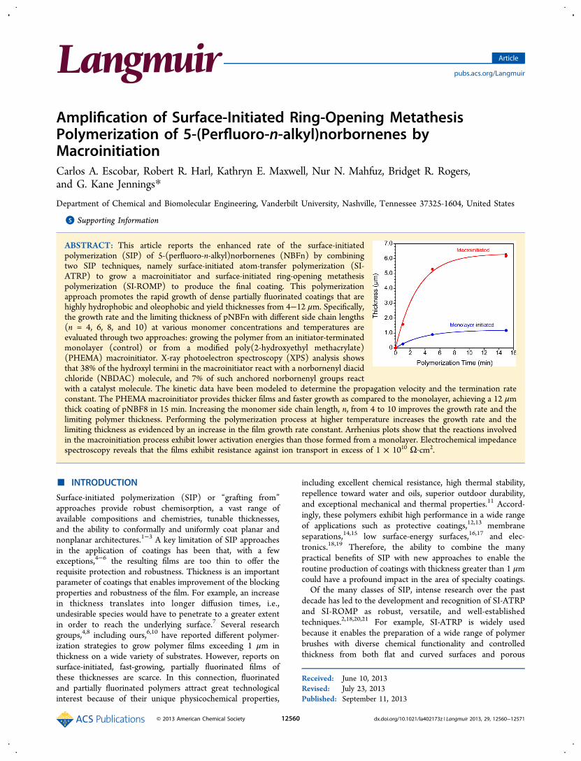
ABSTRACT: This article reports the enhanced rate of the surface-initiatedpolymerization (SIP) of 5-(perfluoro-n-alkyl)norbornenes (NBFn) by combiningtwo SIP techniques, namely surface-initiated atom-transfer polymerization (SI-ATRP) to grow a macroinitiator and surface-initiated ring-opening metathesispolymerization (SI-ROMP) to produce the final coating. This polymerizationapproach promotes the rapid growth of dense partially fluorinated coatings that arehighly hydrophobic and oleophobic and yield thicknesses from 4−12 μm. Specifically,the growth rate and the limiting thickness of pNBFn with different side chain lengths(n = 4, 6, 8, and 10) at various monomer concentrations and temperatures areevaluated through two approaches: growing the polymer from an initiator-terminatedmonolayer (control) or from a modified poly(2-hydroxyethyl methacrylate)(PHEMA) macroinitiator. X-ray photoelectron spectroscopy (XPS) analysis showsthat 38% of the hydroxyl termini in the macroinitiator react with a norbornenyl diacidchloride (NBDAC) molecule, and 7% of such anchored norbornenyl groups reactwith a catalyst molecule. The kinetic data have been modeled to determine the propagation velocity and the termination rateconstant. The PHEMA macroinitiator provides thicker films and faster growth as compared to the monolayer, achieving a 12 μmthick coating of pNBF8 in 15 min. Increasing the monomer side chain length, n, from 4 to 10 improves the growth rate and thelimiting polymer thickness. Performing the polymerization process at higher temperature increases the growth rate and thelimiting thickness as evidenced by an increase in the film growth rate constant. Arrhenius plots show that the reactions involvedin the macroinitiation process exhibit lower activation energies than those formed from a monolayer. Electrochemical impedancespectroscopy reveals that the films exhibit resistance against ion transport in excess of 1 × 10¹⁰ Ω·cm2.
■ INTRODUCTION
Surface-initiated polymerization (SIP) or “grafting from”approaches provide robust chemisorption, a vast range ofavailable compositions and chemistries, tunable thicknesses,and the ability to conformally and uniformly coat planar andnonplanar architectures.1−3 A key limitation of SIP approachesin the application of coatings has been that, with a fewexceptions,4−6 the resulting films are too thin to offer therequisite protection and robustness. Thickness is an importantparameter of coatings that enables improvement of the blockingproperties and robustness of the film. For example, an increasein thickness translates into longer diffusion times, i.e.,undesirable species would have to penetrate to a greater extentin order to reach the underlying surface.7 Several researchgroups,4,8 including ours,6,10 have reported different polymer-ization strategies to grow polymer films exceeding 1 μm inthickness on a wide variety of substrates. However, reports onsurface-initiated, fast-growing, partially fluorinated films ofthese thicknesses are scarce. In this connection, fluorinatedand partially fluorinated polymers attract great technologicalinterest because of their unique physicochemical properties,
including excellent chemical resistance, high thermal stability,repellence toward water and oils, superior outdoor durability,and exceptional mechanical and thermal properties.11 Accord-ingly, these polymers exhibit high performance in a wide rangeof applications such as protective coatings,12,13 membraneseparations,14,15 low surface-energy surfaces,16,17 and elec-tronics.18,19 Therefore, the ability to combine the manypractical benefits of SIP with new approaches to enable theroutine production of coatings with thickness greater than 1 μmcould have a profound impact in the area of specialty coatings.Of the many classes of SIP, intense research over the past
decade has led to the development and recognition of SI-ATRPand SI-ROMP as robust, versatile, and well-establishedtechniques.2,18,20,21 For example, SI-ATRP is widely usedbecause it enables the preparation of a wide range of polymerbrushes with diverse chemical functionality and controlledthickness from both flat and curved surfaces and porous
Received: June 10, 2013Revised: July 23, 2013Published: September 11, 2013
Article
pubs.acs.org/Langmuir
© 2013 American Chemical Society 12560 dx.doi.org/10.1021/la402173z | Langmuir 2013, 29, 12560−12571
substrates.2,22 Similarly, SI-ROMP stands out as a usefultechnique for synthesizing polymers with tailorable function-alities23 to achieve attractive biological, electronic, andmechanical properties.21 Most importantly, SI-ROMP providesfast polymerization rates, even at room temperature in ambientconditions, which result in the rapid growth of thick polymerfilms. Salient advantages of SI-ROMP include tolerance towardfunctional groups, preparation of high-molecular weightpolymers, and preservation of the olefin functionality in theresulting polymer.24 Herein, we report on the synergisticcombination of SI-ATRP and SI-ROMP as a versatile methodto grow exceptionally thick partially fluorinated surface-initiatedpolymer films.Some of the thickest SIP films reported in the literature have
been achieved by employing SI-ATRP or SI-ROMP polymer-ization techniques. For example, Huang et al.8 extended theaqueous solution-phase ATRP method developed by Armes etal.25 to SI-ATRP. They used a mixed halide initiation systemcomprised of CuCl and CuBr2 to successfully and controllablygrow poly(2-hydroxyl methacrylate) (PHEMA) films withthickness up to 700 nm in 12 h of polymerization time. Inaddition, the study demonstrated that the hydroxyl groups inthe PHEMA films could be further derivatized, providing anopportunity to fine-tune the physicochemical properties of thepolymer brushes. Similarly, Brantley et al.26 and Saha et al.27
have grown thick polymer films using SI-ATRP. The SI-ROMPof norbornene and its derivatives are among the thickestpolymer films produced by an SIP technique.28 For instance,Weck et al.18 performed early work on employing SI-ROMP asan alternative technique to overcome the challenges that otherSIP techniques faced at the time, such as side reactions andimpurities on the surface, and were able to grow polymerbrushes of substituted norbornenes on gold with thicknesses upto several hundreds of nanometers. In an effort to createcovalently attached, organic overlayers on silicon (111)substrates, Juang et al.19 combined a chlorination/alkylationprocess in order to form catalyst-anchoring allyl groups on thesilicon substrate with SI-ROMP. As a result, electricallyinsulating polymer layers of polynorbornene with thicknessesof up to 5.5 μm were produced. Similarly, Rutenberg et al.29
employed SI-ROMP to fabricate polymer dielectric layers forfield effect transistors that exhibited a thickness of 1.2 μm.Recently, our group17 reported on the formation of partiallyfluorinated films by means of SI-ROMP exhibiting criticalsurface tensions from 9−18 mN·m−1 and thicknesses in excessof 1 μm.High grafting density is essential in the formation of thick
surface-initiated polymer films.30 Consequently, researchershave resorted to the use of macroinitiators as a tool to enhancegrafting density.3 This approach has been applied, in particular,in the formation of polymer films by SI-ATRP.31 For example,Liu et al.32 deposited poly(glycidyl methacrylate) onto siliconwafers followed by exposure to bromoacetic acid vapor tocreate a macroinitiator for subsequent SI-ATRP. As a result, theinitiator surface density achieved by this method exceeded thatreported for the self-assembled monolayers (SAMs) of ATRPinitiators by a factor of ∼13 (∼ 40·nm−2 for a 6 nm thickmacroinitiator vs ∼3·nm−2 for a self-assembled monolayer).Investigations reporting on the use of macroinitiators inconjunction with SI-ROMP are scarce. In this regard, thework done by Detrembleur and co-workers4 and Voccia et al.5
is worthy of mention. These groups successfully integrated
electrografting33,34 and SI-ROMP as a versatile approach toprepare dense polymer films on conducting substrates.The efficiency and quality of fluorinated and partially
fluorinated films, which often yield critical surface tensions aslow or lower than fully fluorinated polymers because of thesegregation of the fluorocarbon chains to the interface,16,17
depend to a great extent on the deposition techniques used tocreate them. For example, conventional deposition methodsbased on physisorption give rise to weak interactions thatundermine the adhesion between the film and the solid surface,rendering the films unstable.16,17,35 Conversely, SIP is an idealapproach to avert such deficiency, as demonstrated by severalgroups.36 This manuscript describes the sequential use of twoversatile SIP techniques, namely SI-ATRP and SI-ROMP, inthe preparation of thick partially fluorinated polymer filmsprepared from 5-(perfluoro-n-alkyl)norbornenes (NBFn),where n represents the number of carbons present in thefluorocarbon side chain, e.g., 4, 6, 8, and 10.
■ EXPERIMENTAL SECTIONMaterials. 4-Mercapto-1-butanol (97%), Grubbs catalyst second
generation (1,3-bis-(2,4,6-trimethylphenyl)-2-(imidazolidinylidene)(dichlorophenylmethylene) (tricyclohexylphosphine) ruthenium),trans-3,6-endomethylene-1,2,3,6-tetrahydrophthaloyl chloride(NBDAC) (97%), copper(I) chloride (CuCl) (99.995+%), copper(II)bromide (CuBr2) (99.999%), 2,2′-bipyridine (bpy, 99+%), N,N-dimethylformamide (DMF, 99.9%), 2-hydroxyethyl methacrylate(HEMA, >99%), 1H,1H,2H-perfluoro-1-hexene (99%), 1H,1H,2H-perfluoro-1-octene (99%), 1H,1H,2H-perfluoro-1-decene (99%),hydroquinone, potassium ferricyanide (III) (K3Fe(CN)6), andpotassium ferrocyanide (II) (K4Fe(CN)6·3H2O) were acquired fromSigma-Aldrich. 1H,1H,2H-Perfluoro-1-dodecene (97%) was purchasedfrom Matrix Scientific. n-Hexadecane (99%) was obtained from AcrosOrganics. Methylene chloride (DCM) (99%) and sodium sulfate(Na2SO4) were purchased from Fisher. Gold shot (99.99%) wasobtained from J&J Materials, and silicon (100) wafers were purchasedfrom WRS Materials. Chrome-plated tungsten rods were obtainedfrom R. D. Mathis. Deionized water (16.7 MΩ) was purified with aModu-Pure filtration (Continental Water Systems Corporation)system and used for rinsing. Ethanol (200 proof) was obtained fromAAPER and used as received. Nitrogen gas was obtained from ALcompressed gases. The synthesis of 5-(perfluoro-n-alkyl)norbornenesand the initiator-terminated disulfide, (BrC(CH3)2COO(CH2)11S)2, isdescribed elsewhere.17,37,38
Preparation of Gold Substrates. Silicon wafers were cleanedwith ethanol and water and dried in a nitrogen stream. Subsequently,the wafers were placed inside a CVC-PSM66 evaporator in order tosequentially evaporate 100 and 1250 Å of chromium and gold,respectively, onto the wafers using an evaporation rate of 1−2 Å/s at abase pressure of <4 × 10⁻⁶ Torr. After the evaporation process, waferswere cut into samples of 1.2 cm × 3.5 cm in size.
Polymerization. Two approaches were used to grow partiallyfluorinated polymer films from gold substrates, namely initiation froma monolayer and initiation from a macroinitiator. In both cases, thefilms were grown from 0.05, 0.2, and 1 M monomer solutions andallowed to polymerize for 1, 5, and 15 min in each concentration. Inthe monolayer approach, the gold samples were exposed to a 1 mMethanolic solution of 4-mercapto-1-butanol for at least 1 h to form achemisorbed hydroxyl-terminated SAM. Afterward, samples wererinsed in ethanol and dried in a stream of nitrogen. The driedsubstrates were exposed to a 5 mM solution of NBDAC in DCM for30 min. Then, samples were rinsed with DCM and ethanol and driedin a stream of nitrogen. These substrates were exposed to a 5 mMsolution of Grubbs second-generation catalyst in DCM for 10 min.Upon removal from solution, samples were rinsed with DCM andimmediately placed in a solution of NBFn (n = 4, 6, 8, 10) in DCM for
Langmuir Article
dx.doi.org/10.1021/la402173z | Langmuir 2013, 29, 12560−1257112561
1, 5, or 15 min. After polymerization, samples were rinsed with DCM,ethanol, and water and dried in a stream of nitrogen.In the macroinitiator approach, the gold substrates were
sequentially exposed to two surface-initiated polymerization processes,specifically, SI-ATRP and SI-ROMP. SI-ATRP was performed to growa PHEMA film, which, after modification, served as a macroinitiatorlayer for the SI-ROMP process. The procedure to grow PHEMA fromthe gold substrates is similar to that reported by Brantley et al.26
Briefly, gold substrates were exposed to a 1 mM ethanolic solution ofthe disulfide ATRP initiator (BrC(CH3)2COO(CH2)11S)2 for 24 h.
8,38
Afterward, these initiator-bearing samples were rinsed with ethanol,dried in a stream of nitrogen, and placed in vials sealed with rubbersepta. These vials underwent a subsequent degassing and backfillingprocess with nitrogen. The polymerization mixture consisting of CuI/CuII/bpy (69 mM CuCl, 20 mM CuBr2, 195 mM bpy) in a 50:50 v:vwater/HEMA solution, contained in a Schlenk flask sealed with arubber septum, was exposed to a degassing process by performingthree freeze−pump−thaw cycles. Subsequently, the mixture wastransferred via cannula into the vials containing the ATRP-activesubstrates. After 12 h of polymerization at room temperature, sampleswere rinsed with water and DMF and dried with nitrogen.To perform the SI-ROMP process, the PHEMA samples were first
exposed to a 20 mM NBDAC solution in DMF for 3 h and werethoroughly rinsed with DMF and ethanol after removal from solutionand dried in a stream of nitrogen. In a similar manner to that in themonolayer initiation process, samples were exposed to a 5 mMsolution of Grubbs second-generation catalyst in DCM for 10 min.Subsequently, samples were thoroughly rinsed with DCM andimmediately placed in a solution of NBFn (n = 4, 6, 8, 10) inDCM for 1, 5, or 15 min. After polymerization, the samples wererinsed with DCM, ethanol, and water and dried with a stream ofnitrogen. All SI-ROMP reactions took place under ambient conditionsunless otherwise indicated.
■ RESULTS AND DISCUSSIONThe polymerization of partially fluorinated films from gold-coated substrates was achieved via monolayer initiation andmacroinitiation. In the former process,17 exposure of a SAMprepared from 4-mercapto-1-butanol on gold to an NBDACsolution led to the coupling of the norbornenyl group to theunderlying hydroxyl monolayer via ester linkages. Subsequent
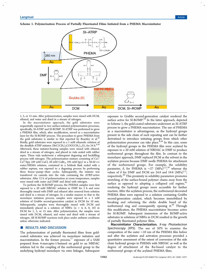
exposure to Grubbs second-generation catalyst rendered thesurface active for SI-ROMP.24 In the latter approach, depictedin Scheme 1, the gold-coated substrates underwent an SI-ATRPprocess to grow a PHEMA macroinitiator. The use of PHEMAas a macroinitiator is advantageous, as the hydroxyl groupspresent in the side chain of each repeating unit can be furtherderivatized to introduce initiating groups from which otherpolymerization processes can take place.8,26 In this case, someof the hydroxyl groups in the PHEMA film were acylated byexposure to a 20 mM solution of NBDAC in DMF to producenorbornenyl groups throughout the film. In contrast to themonolayer approach, DMF replaced DCM as the solvent in theacylation process because DMF swells PHEMA for attachmentof the norbornenyl groups. For example, the solubilityparameter, δ, for PHEMA is ∼27 (MPa)1/2,39 whereas thevalues of δ for DMF and DCM are 24.8 and 19.8 (MPa)1/2,respectively.40 This proximity in solubility parameters promotesstretching of the surface-bound polymer chains away from thesurface as opposed to adopting a collapsed coil regime,41
rendering the hydroxyl groups more accessible for furtherreaction. After the acylation process, the norbornenyl-decoratedPHEMA films were exposed to a solution containing Grubbssecond-generation catalyst, which becomes immobilized bybreaking and reforming the olefin double bond of thenorbornenyl ring and consequently opening it.29 Throughthis modification, the PHEMA macroinitiator becomes activefor SI-ROMP. Subsequent immersion of the ROMP-activesubstrates in solutions of NBFn in DCM resulted in the growthof partially fluorinated polymer films.
Macroinitiator Characterization. X-ray PhotoelectronSpectroscopy (XPS). The use of XPS to examine thecomposition of the outer ∼10 nm of the PHEMA film beforeand after the acylation and activation processes provided aquantitative assessment of the extent of conversion of the sidechain hydroxyl groups in PHEMA with NBDAC as well as thedegree of attachment of the Ru-based catalyst to thenorbornenyl groups of the acylated PHEMA films.
Scheme 1. Polymerization Process of Partially Fluorinated Films Initiated from a PHEMA Macroinitiator
Langmuir Article
dx.doi.org/10.1021/la402173z | Langmuir 2013, 29, 12560−1257112562
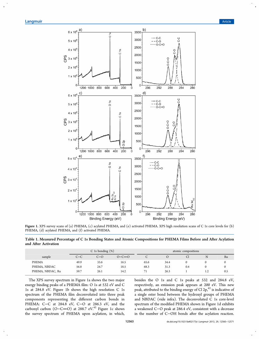
The XPS survey spectrum in Figure 1a shows the two majorenergy binding peaks of a PHEMA film: O 1s at 532 eV and C1s at 284.8 eV. Figure 1b shows the high resolution C 1sspectrum of the PHEMA film deconvoluted into three peakcomponents representing the different carbon bonds inPHEMA: C−C at 284.8 eV, C−O at 286.3 eV, and thecarbonyl carbon (O−CO) at 288.7 eV.42 Figure 1c showsthe survey spectrum of PHEMA upon acylation, in which,
besides the O 1s and C 1s peaks at 532 and 284.8 eV,respectively, an emission peak appears at 200 eV. This newpeak, attributed to the binding energy of Cl 2p,42 is indicative ofa single ester bond between the hydroxyl groups of PHEMAand NBDAC (vide infra). The deconvoluted C 1s core-levelspectrum of the modified PHEMA shown in Figure 1d exhibitsa weakened C−O peak at 286.4 eV, consistent with a decreasein the number of C−OH bonds after the acylation reaction.
Figure 1. XPS survey scans of (a) PHEMA, (c) acylated PHEMA, and (e) activated PHEMA. XPS high resolution scans of C 1s core levels for (b)PHEMA, (d) acylated PHEMA, and (f) activated PHEMA.
Table 1. Measured Percentage of C 1s Bonding States and Atomic Compositions for PHEMA Films Before and After Acylationand After Activation
C 1s bonding (%) atomic compositions
sample C−C C−O O−CO C O Cl N Ru
PHEMA 49.9 33.6 16.5 65.6 34.4 0 0 0PHEMA, NBDAC 56.8 24.7 18.5 68.3 31.3 0.4 0 0PHEMA, NBDAC, Ru 59.7 26.1 14.2 71 26.3 1 1.2 0.5
Langmuir Article
dx.doi.org/10.1021/la402173z | Langmuir 2013, 29, 12560−1257112563
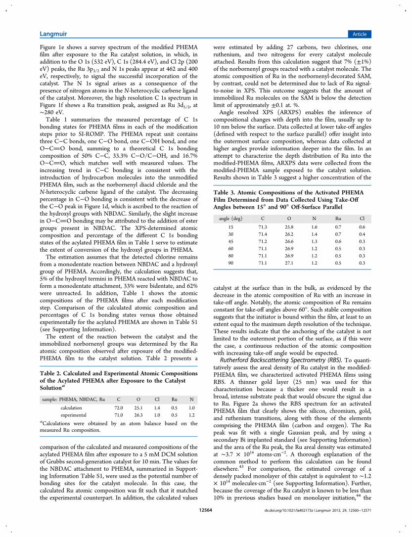
Figure 1e shows a survey spectrum of the modified PHEMAfilm after exposure to the Ru catalyst solution, in which, inaddition to the O 1s (532 eV), C 1s (284.4 eV), and Cl 2p (200eV) peaks, the Ru 3p3/2 and N 1s peaks appear at 462 and 400eV, respectively, to signal the successful incorporation of thecatalyst. The N 1s signal arises as a consequence of thepresence of nitrogen atoms in the N-heterocyclic carbene ligandof the catalyst. Moreover, the high resolution C 1s spectrum inFigure 1f shows a Ru transition peak, assigned as Ru 3d5/2, at∼280 eV.Table 1 summarizes the measured percentage of C 1s
bonding states for PHEMA films in each of the modificationsteps prior to SI-ROMP. The PHEMA repeat unit containsthree C−C bonds, one C−O bond, one C−OH bond, and oneO−CO bond, summing to a theoretical C 1s bondingcomposition of 50% C−C, 33.3% C−O/C−OH, and 16.7%O−CO, which matches well with measured values. Theincreasing trend in C−C bonding is consistent with theintroduction of hydrocarbon molecules into the unmodifiedPHEMA film, such as the norbornenyl diacid chloride and theN-heterocyclic carbene ligand of the catalyst. The decreasingpercentage in C−O bonding is consistent with the decrease ofthe C−O peak in Figure 1d, which is ascribed to the reaction ofthe hydroxyl groups with NBDAC. Similarly, the slight increasein O−CO bonding may be attributed to the addition of estergroups present in NBDAC. The XPS-determined atomiccomposition and percentage of the different C 1s bondingstates of the acylated PHEMA film in Table 1 serve to estimatethe extent of conversion of the hydroxyl groups in PHEMA.The estimation assumes that the detected chlorine remains
from a monodentate reaction between NBDAC and a hydroxylgroup of PHEMA. Accordingly, the calculation suggests that,5% of the hydroxyl termini in PHEMA reacted with NBDAC toform a monodentate attachment, 33% were bidentate, and 62%were unreacted. In addition, Table 1 shows the atomiccompositions of the PHEMA films after each modificationstep. Comparison of the calculated atomic composition andpercentages of C 1s bonding states versus those obtainedexperimentally for the acylated PHEMA are shown in Table S1(see Supporting Information).The extent of the reaction between the catalyst and the
immobilized norbornenyl groups was determined by the Ruatomic composition observed after exposure of the modified-PHEMA film to the catalyst solution. Table 2 presents a
comparison of the calculated and measured compositions of theacylated PHEMA film after exposure to a 5 mM DCM solutionof Grubbs second-generation catalyst for 10 min. The values forthe NBDAC attachment to PHEMA, summarized in Support-ing Information Table S1, were used as the potential number ofbonding sites for the catalyst molecule. In this case, thecalculated Ru atomic composition was fit such that it matchedthe experimental counterpart. In addition, the calculated values
were estimated by adding 27 carbons, two chlorines, oneruthenium, and two nitrogens for every catalyst moleculeattached. Results from this calculation suggest that 7% (±1%)of the norbornenyl groups reacted with a catalyst molecule. Theatomic composition of Ru in the norbornenyl-decorated SAM,by contrast, could not be determined due to lack of Ru signal-to-noise in XPS. This outcome suggests that the amount ofimmobilized Ru molecules on the SAM is below the detectionlimit of approximately ±0.1 at. %.Angle resolved XPS (ARXPS) enables the inference of
compositional changes with depth into the film, usually up to10 nm below the surface. Data collected at lower take-off angles(defined with respect to the surface parallel) offer insight intothe outermost surface composition, whereas data collected athigher angles provide information deeper into the film. In anattempt to characterize the depth distribution of Ru into themodified-PHEMA films, ARXPS data were collected from themodified-PHEMA sample exposed to the catalyst solution.Results shown in Table 3 suggest a higher concentration of the
catalyst at the surface than in the bulk, as evidenced by thedecrease in the atomic composition of Ru with an increase intake-off angle. Notably, the atomic composition of Ru remainsconstant for take-off angles above 60°. Such stable compositionsuggests that the initiator is bound within the film, at least to anextent equal to the maximum depth resolution of the technique.These results indicate that the anchoring of the catalyst is notlimited to the outermost portion of the surface, as if this werethe case, a continuous reduction of the atomic compositionwith increasing take-off angle would be expected.
Rutherford Backscattering Spectrometry (RBS). To quanti-tatively assess the areal density of Ru catalyst in the modified-PHEMA film, we characterized activated PHEMA films usingRBS. A thinner gold layer (25 nm) was used for thischaracterization because a thicker one would result in abroad, intense substrate peak that would obscure the signal dueto Ru. Figure 2a shows the RBS spectrum for an activatedPHEMA film that clearly shows the silicon, chromium, gold,and ruthenium transitions, along with those of the elementscomprising the PHEMA film (carbon and oxygen). The Rupeak was fit with a single Gaussian peak, and by using asecondary Bi implanted standard (see Supporting Information)and the area of the Ru peak, the Ru areal density was estimatedat ∼3.7 × 10¹⁴ atoms·cm−2. A thorough explanation of thecommon method to perform this calculation can be foundelsewhere.43 For comparison, the estimated coverage of adensely packed monolayer of this catalyst is equivalent to ∼1.2× 10¹⁴ molecules·cm−2 (see Supporting Information). Further,because the coverage of the Ru catalyst is known to be less than10% in previous studies based on monolayer initiation,44 the
Table 2. Calculated and Experimental Atomic Compositionsof the Acylated PHEMA after Exposure to the CatalystSolutiona
sample: PHEMA, NBDAC, Ru C O Cl Ru N
calculation 72.0 25.1 1.4 0.5 1.0experimental 71.0 26.3 1.0 0.5 1.2
aCalculations were obtained by an atom balance based on themeasured Ru composition.
Table 3. Atomic Compositions of the Activated PHEMAFilm Determined from Data Collected Using Take-Off
Angles between 15° and 90° Off-Surface Parallel
angle (deg) C O N Ru Cl
15 71.3 25.8 1.6 0.7 0.630 71.4 26.2 1.4 0.7 0.445 71.2 26.6 1.3 0.6 0.360 71.1 26.9 1.2 0.5 0.380 71.1 26.9 1.2 0.5 0.390 71.1 27.1 1.2 0.5 0.3
Langmuir Article
dx.doi.org/10.1021/la402173z | Langmuir 2013, 29, 12560−1257112564
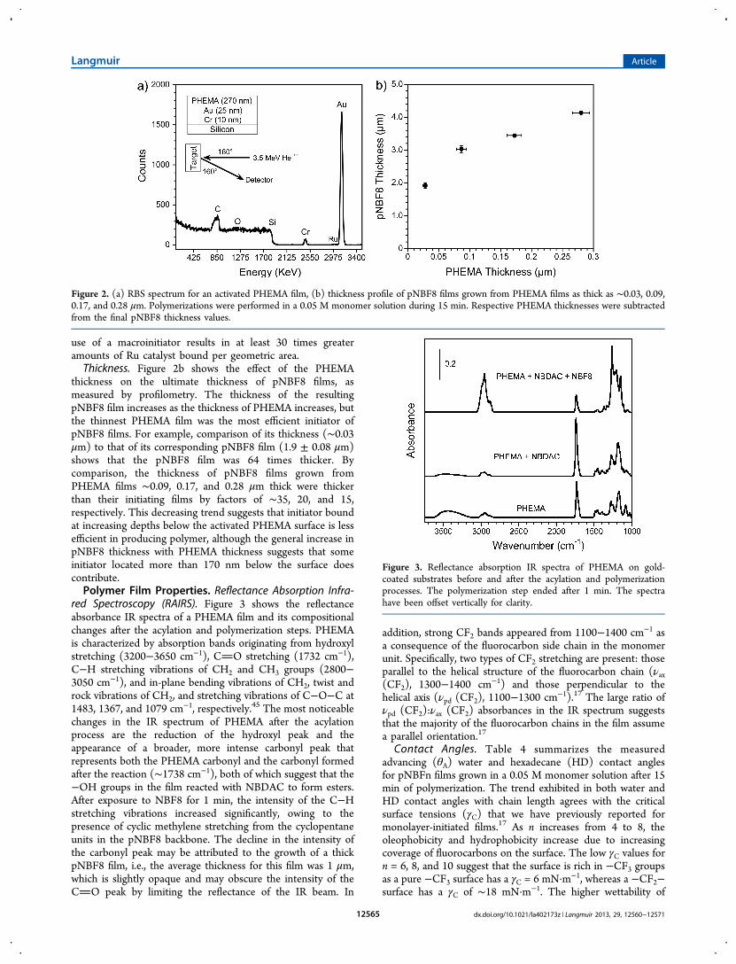
use of a macroinitiator results in at least 30 times greateramounts of Ru catalyst bound per geometric area.Thickness. Figure 2b shows the effect of the PHEMA
thickness on the ultimate thickness of pNBF8 films, asmeasured by profilometry. The thickness of the resultingpNBF8 film increases as the thickness of PHEMA increases, butthe thinnest PHEMA film was the most efficient initiator ofpNBF8 films. For example, comparison of its thickness (∼0.03μm) to that of its corresponding pNBF8 film (1.9 ± 0.08 μm)shows that the pNBF8 film was 64 times thicker. Bycomparison, the thickness of pNBF8 films grown fromPHEMA films ∼0.09, 0.17, and 0.28 μm thick were thickerthan their initiating films by factors of ∼35, 20, and 15,respectively. This decreasing trend suggests that initiator boundat increasing depths below the activated PHEMA surface is lessefficient in producing polymer, although the general increase inpNBF8 thickness with PHEMA thickness suggests that someinitiator located more than 170 nm below the surface doescontribute.Polymer Film Properties. Reflectance Absorption Infra-
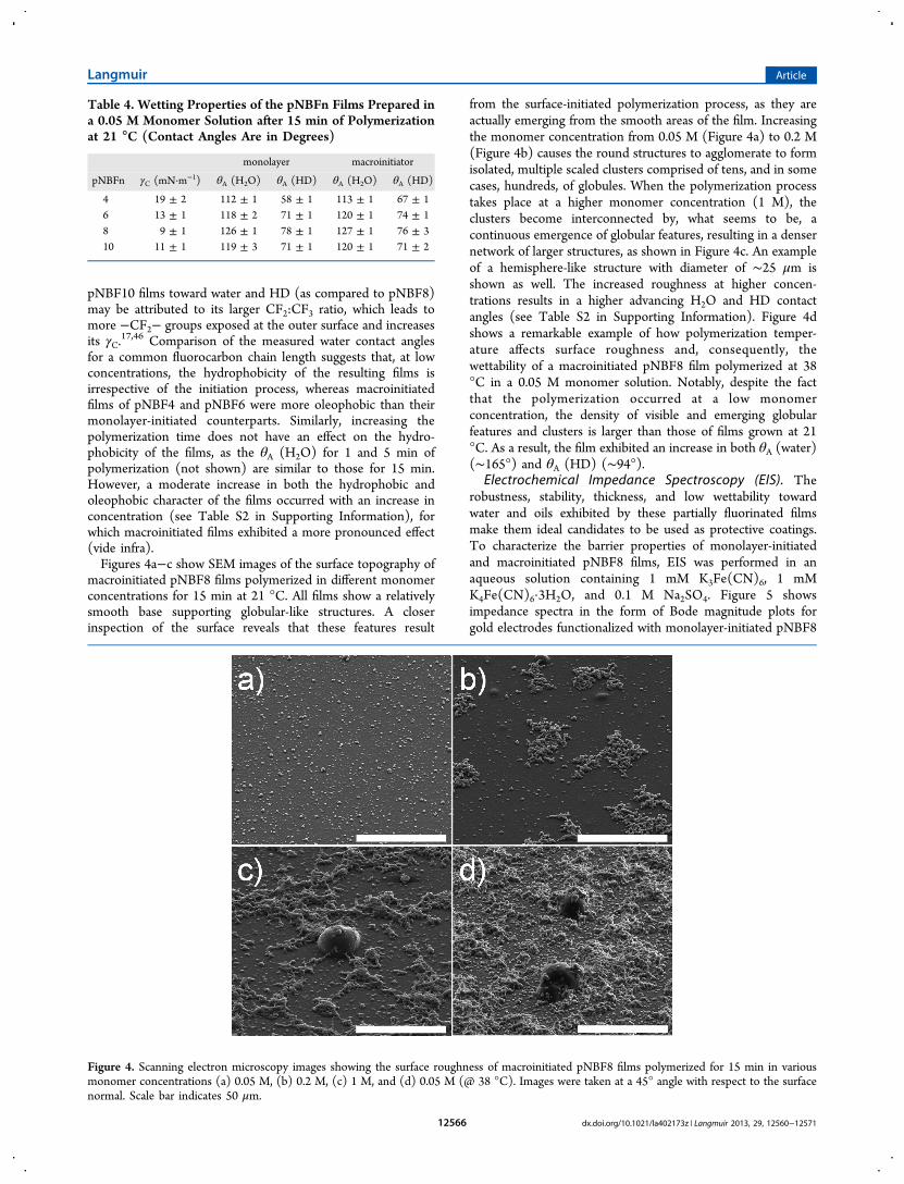
red Spectroscopy (RAIRS). Figure 3 shows the reflectanceabsorbance IR spectra of a PHEMA film and its compositionalchanges after the acylation and polymerization steps. PHEMAis characterized by absorption bands originating from hydroxylstretching (3200−3650 cm−1), CO stretching (1732 cm−1),C−H stretching vibrations of CH2 and CH3 groups (2800−3050 cm−1), and in-plane bending vibrations of CH2, twist androck vibrations of CH2, and stretching vibrations of C−O−C at1483, 1367, and 1079 cm−1, respectively.45 The most noticeablechanges in the IR spectrum of PHEMA after the acylationprocess are the reduction of the hydroxyl peak and theappearance of a broader, more intense carbonyl peak thatrepresents both the PHEMA carbonyl and the carbonyl formedafter the reaction (∼1738 cm−1), both of which suggest that the−OH groups in the film reacted with NBDAC to form esters.After exposure to NBF8 for 1 min, the intensity of the C−Hstretching vibrations increased significantly, owing to thepresence of cyclic methylene stretching from the cyclopentaneunits in the pNBF8 backbone. The decline in the intensity ofthe carbonyl peak may be attributed to the growth of a thickpNBF8 film, i.e., the average thickness for this film was 1 μm,which is slightly opaque and may obscure the intensity of theCO peak by limiting the reflectance of the IR beam. In
addition, strong CF2 bands appeared from 1100−1400 cm−1 asa consequence of the fluorocarbon side chain in the monomerunit. Specifically, two types of CF2 stretching are present: thoseparallel to the helical structure of the fluorocarbon chain (νax(CF2), 1300−1400 cm−1) and those perpendicular to thehelical axis (νpd (CF2), 1100−1300 cm−1).17 The large ratio ofνpd (CF2):νax (CF2) absorbances in the IR spectrum suggeststhat the majority of the fluorocarbon chains in the film assumea parallel orientation.17
Contact Angles. Table 4 summarizes the measuredadvancing (θA) water and hexadecane (HD) contact anglesfor pNBFn films grown in a 0.05 M monomer solution after 15min of polymerization. The trend exhibited in both water andHD contact angles with chain length agrees with the criticalsurface tensions (γC) that we have previously reported formonolayer-initiated films.17 As n increases from 4 to 8, theoleophobicity and hydrophobicity increase due to increasingcoverage of fluorocarbons on the surface. The low γC values forn = 6, 8, and 10 suggest that the surface is rich in −CF3 groupsas a pure −CF3 surface has a γC = 6 mN·m−1, whereas a −CF2−surface has a γC of ∼18 mN·m−1. The higher wettability of
Figure 2. (a) RBS spectrum for an activated PHEMA film, (b) thickness profile of pNBF8 films grown from PHEMA films as thick as ∼0.03, 0.09,0.17, and 0.28 μm. Polymerizations were performed in a 0.05 M monomer solution during 15 min. Respective PHEMA thicknesses were subtractedfrom the final pNBF8 thickness values.
Figure 3. Reflectance absorption IR spectra of PHEMA on gold-coated substrates before and after the acylation and polymerizationprocesses. The polymerization step ended after 1 min. The spectrahave been offset vertically for clarity.
Langmuir Article
dx.doi.org/10.1021/la402173z | Langmuir 2013, 29, 12560−1257112565
pNBF10 films toward water and HD (as compared to pNBF8)may be attributed to its larger CF2:CF3 ratio, which leads tomore −CF2− groups exposed at the outer surface and increasesits γC.
17,46 Comparison of the measured water contact anglesfor a common fluorocarbon chain length suggests that, at lowconcentrations, the hydrophobicity of the resulting films isirrespective of the initiation process, whereas macroinitiatedfilms of pNBF4 and pNBF6 were more oleophobic than theirmonolayer-initiated counterparts. Similarly, increasing thepolymerization time does not have an effect on the hydro-phobicity of the films, as the θA (H2O) for 1 and 5 min ofpolymerization (not shown) are similar to those for 15 min.However, a moderate increase in both the hydrophobic andoleophobic character of the films occurred with an increase inconcentration (see Table S2 in Supporting Information), forwhich macroinitiated films exhibited a more pronounced effect(vide infra).Figures 4a−c show SEM images of the surface topography of
macroinitiated pNBF8 films polymerized in different monomerconcentrations for 15 min at 21 °C. All films show a relativelysmooth base supporting globular-like structures. A closerinspection of the surface reveals that these features result
from the surface-initiated polymerization process, as they areactually emerging from the smooth areas of the film. Increasingthe monomer concentration from 0.05 M (Figure 4a) to 0.2 M(Figure 4b) causes the round structures to agglomerate to formisolated, multiple scaled clusters comprised of tens, and in somecases, hundreds, of globules. When the polymerization processtakes place at a higher monomer concentration (1 M), theclusters become interconnected by, what seems to be, acontinuous emergence of globular features, resulting in a densernetwork of larger structures, as shown in Figure 4c. An exampleof a hemisphere-like structure with diameter of ∼25 μm isshown as well. The increased roughness at higher concen-trations results in a higher advancing H2O and HD contactangles (see Table S2 in Supporting Information). Figure 4dshows a remarkable example of how polymerization temper-ature affects surface roughness and, consequently, thewettability of a macroinitiated pNBF8 film polymerized at 38°C in a 0.05 M monomer solution. Notably, despite the factthat the polymerization occurred at a low monomerconcentration, the density of visible and emerging globularfeatures and clusters is larger than those of films grown at 21°C. As a result, the film exhibited an increase in both θA (water)(∼165°) and θA (HD) (∼94°).
Electrochemical Impedance Spectroscopy (EIS). Therobustness, stability, thickness, and low wettability towardwater and oils exhibited by these partially fluorinated filmsmake them ideal candidates to be used as protective coatings.To characterize the barrier properties of monolayer-initiatedand macroinitiated pNBF8 films, EIS was performed in anaqueous solution containing 1 mM K3Fe(CN)6, 1 mMK4Fe(CN)6·3H2O, and 0.1 M Na2SO4. Figure 5 showsimpedance spectra in the form of Bode magnitude plots forgold electrodes functionalized with monolayer-initiated pNBF8
Table 4. Wetting Properties of the pNBFn Films Prepared ina 0.05 M Monomer Solution after 15 min of Polymerizationat 21 °C (Contact Angles Are in Degrees)
monolayer macroinitiator
pNBFn γC (mN·m−1) θA (H2O) θA (HD) θA (H2O) θA (HD)
4 19 ± 2 112 ± 1 58 ± 1 113 ± 1 67 ± 16 13 ± 1 118 ± 2 71 ± 1 120 ± 1 74 ± 18 9 ± 1 126 ± 1 78 ± 1 127 ± 1 76 ± 310 11 ± 1 119 ± 3 71 ± 1 120 ± 1 71 ± 2
Figure 4. Scanning electron microscopy images showing the surface roughness of macroinitiated pNBF8 films polymerized for 15 min in variousmonomer concentrations (a) 0.05 M, (b) 0.2 M, (c) 1 M, and (d) 0.05 M (@ 38 °C). Images were taken at a 45° angle with respect to the surfacenormal. Scale bar indicates 50 μm.
Langmuir Article
dx.doi.org/10.1021/la402173z | Langmuir 2013, 29, 12560−1257112566
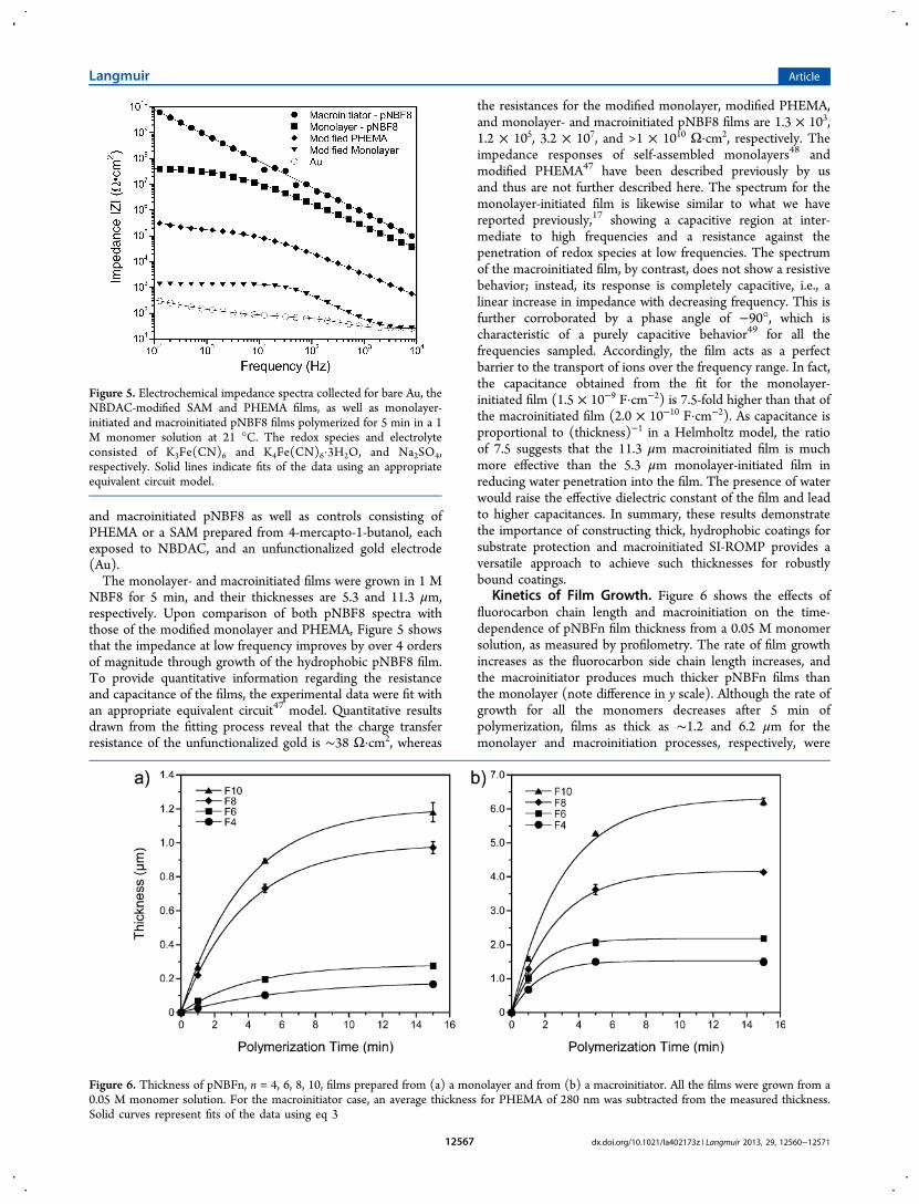
and macroinitiated pNBF8 as well as controls consisting ofPHEMA or a SAM prepared from 4-mercapto-1-butanol, eachexposed to NBDAC, and an unfunctionalized gold electrode(Au).The monolayer- and macroinitiated films were grown in 1 M
NBF8 for 5 min, and their thicknesses are 5.3 and 11.3 μm,respectively. Upon comparison of both pNBF8 spectra withthose of the modified monolayer and PHEMA, Figure 5 showsthat the impedance at low frequency improves by over 4 ordersof magnitude through growth of the hydrophobic pNBF8 film.To provide quantitative information regarding the resistanceand capacitance of the films, the experimental data were fit withan appropriate equivalent circuit47 model. Quantitative resultsdrawn from the fitting process reveal that the charge transferresistance of the unfunctionalized gold is ∼38 Ω·cm2, whereas
the resistances for the modified monolayer, modified PHEMA,and monolayer- and macroinitiated pNBF8 films are 1.3 × 103,1.2 × 105, 3.2 × 10⁷, and >1 × 10¹⁰ Ω·cm2, respectively. Theimpedance responses of self-assembled monolayers48 andmodified PHEMA47 have been described previously by usand thus are not further described here. The spectrum for themonolayer-initiated film is likewise similar to what we havereported previously,17 showing a capacitive region at inter-mediate to high frequencies and a resistance against thepenetration of redox species at low frequencies. The spectrumof the macroinitiated film, by contrast, does not show a resistivebehavior; instead, its response is completely capacitive, i.e., alinear increase in impedance with decreasing frequency. This isfurther corroborated by a phase angle of −90°, which ischaracteristic of a purely capacitive behavior49 for all thefrequencies sampled. Accordingly, the film acts as a perfectbarrier to the transport of ions over the frequency range. In fact,the capacitance obtained from the fit for the monolayer-initiated film (1.5 × 10⁻⁹ F·cm−2) is 7.5-fold higher than that ofthe macroinitiated film (2.0 × 10⁻¹⁰ F·cm−2). As capacitance isproportional to (thickness)−1 in a Helmholtz model, the ratioof 7.5 suggests that the 11.3 μm macroinitiated film is muchmore effective than the 5.3 μm monolayer-initiated film inreducing water penetration into the film. The presence of waterwould raise the effective dielectric constant of the film and leadto higher capacitances. In summary, these results demonstratethe importance of constructing thick, hydrophobic coatings forsubstrate protection and macroinitiated SI-ROMP provides aversatile approach to achieve such thicknesses for robustlybound coatings.
Kinetics of Film Growth. Figure 6 shows the effects offluorocarbon chain length and macroinitiation on the time-dependence of pNBFn film thickness from a 0.05 M monomersolution, as measured by profilometry. The rate of film growthincreases as the fluorocarbon side chain length increases, andthe macroinitiator produces much thicker pNBFn films thanthe monolayer (note difference in y scale). Although the rate ofgrowth for all the monomers decreases after 5 min ofpolymerization, films as thick as ∼1.2 and 6.2 μm for themonolayer and macroinitiation processes, respectively, were
Figure 5. Electrochemical impedance spectra collected for bare Au, theNBDAC-modified SAM and PHEMA films, as well as monolayer-initiated and macroinitiated pNBF8 films polymerized for 5 min in a 1M monomer solution at 21 °C. The redox species and electrolyteconsisted of K3Fe(CN)6 and K4Fe(CN)6·3H2O, and Na2SO4,respectively. Solid lines indicate fits of the data using an appropriateequivalent circuit model.
Figure 6. Thickness of pNBFn, n = 4, 6, 8, 10, films prepared from (a) a monolayer and from (b) a macroinitiator. All the films were grown from a0.05 M monomer solution. For the macroinitiator case, an average thickness for PHEMA of 280 nm was subtracted from the measured thickness.Solid curves represent fits of the data using eq 3
Langmuir Article
dx.doi.org/10.1021/la402173z | Langmuir 2013, 29, 12560−1257112567
achieved with pNBF10 in just 15 min at this low monomerconcentration.The deceleration of film growth is common in surface-
initiated polymerizations8,44,50 and may be attributed to aprogressive deactivation of the Ru catalyst by, for example,dissolved oxygen in the monomer solution51,52 and/or to theprompt occlusion of the active Ru centers from the monomerby the fast-growing pNBFn film. The former was somewhatexpected, as both the activation of the substrates and thepolymerization process took place under ambient conditions. Insummary, after 15 min of polymerization, the macroinitiatedpNBFn films were thicker than their monolayer counterparts bya factor of 9 for both pNBF4 and pNBF6, and 4 and 5 forpNBF8 and pNBF10.To estimate the relative propagation and termination rate
constants involved in the growth of these pNBFn films, andtherefore, the relative reactivity of the monomers used, weemployed a kinetic model developed by Harada et al.44 In thismodel, the change of film thickness (d) as a function of timewas given as
ρ= − −
⎛⎝⎜
⎞⎠⎟⎛⎝⎜
⎞⎠⎟d
k M
km P
e(1 )k tp
t
0 I t
(1)
where kp is the propagation rate constant, M is theconcentration of the monomer in solution, kt is the terminationrate constant, m0 is the mass of the monomer unit, PI is theinitial number of active catalyst sites per unit area, and ρ is thedensity of the polymer. The model assumes that the growingpolymer chains add one monomer unit at a time at apropagation rate of kp in a second-order reaction and that theactive catalyst may become irreversibly deactivated in each stepby a first-order reaction at a rate of kt. Because the value of PIfor the norbornenyl-decorated SAM is below the detectionlimit, as noted earlier in the XPS results, we opted for thecombination of kp and PI as a single rate term (K) for filmgrowth
=K k Pp I (2)
which expresses both initiation and propagation. Accordingly,this term allows a general comparison of film growth kineticsfor this series of monomers. As a result, eq 1 becomes
ρ= − −
⎛⎝⎜
⎞⎠⎟d
KMmk
e(1 )k t0
t
t
(3)
In addition, we approximated the density of the polymerfilms, i.e., pNBF4, pNBF6, pNBF8, and pNBF10, to that of themonomers, as measured by pycnometry, to be 1.46, 1.54, 1.62,and 1.70 g·cm−3, respectively.Table 5 summarizes the estimated values for K and kt
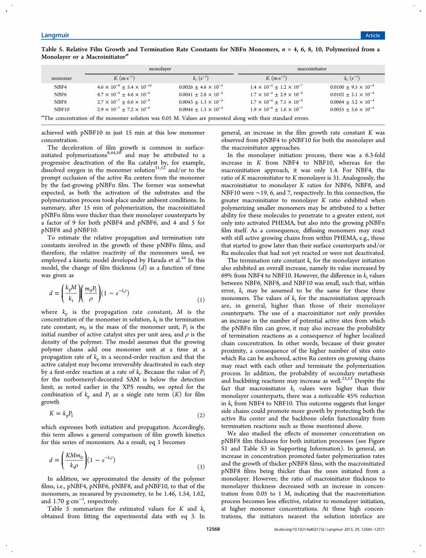
obtained from fitting the experimental data with eq 3. In
general, an increase in the film growth rate constant K wasobserved from pNBF4 to pNBF10 for both the monolayer andthe macroinitiator approaches.In the monolayer initiation process, there was a 6.3-fold
increase in K from NBF4 to NBF10, whereas for themacroinitiation approach, it was only 1.4. For NBF4, theratio of K macroinitiator to K monolayer is 31. Analogously, themacroinitiator to monolayer K ratios for NBF6, NBF8, andNBF10 were ∼19, 6, and 7, respectively. In this connection, thegreater macroinitiator to monolayer K ratio exhibited whenpolymerizing smaller monomers may be attributed to a betterability for these molecules to penetrate to a greater extent, notonly into activated PHEMA, but also into the growing pNBFnfilm itself. As a consequence, diffusing monomers may reactwith still active growing chains from within PHEMA, e.g., thosethat started to grow later than their surface counterparts and/orRu molecules that had not yet reacted or were not deactivated.The termination rate constant kt for the monolayer initiation
also exhibited an overall increase, namely its value increased by69% from NBF4 to NBF10. However, the difference in kt valuesbetween NBF6, NBF8, and NBF10 was small, such that, withinerror, kt may be assumed to be the same for these threemonomers. The values of kt for the macroinitiation approachare, in general, higher than those of their monolayercounterparts. The use of a macroinitiator not only providesan increase in the number of potential active sites from whichthe pNBFn film can grow, it may also increase the probabilityof termination reactions as a consequence of higher localizedchain concentration. In other words, because of their greaterproximity, a consequence of the higher number of sites ontowhich Ru can be anchored, active Ru centers on growing chainsmay react with each other and terminate the polymerizationprocess. In addition, the probability of secondary metathesisand backbiting reactions may increase as well.23,53 Despite thefact that macroinitiator kt values were higher than theirmonolayer counterparts, there was a noticeable 45% reductionin kt from NBF4 to NBF10. This outcome suggests that longerside chains could promote more growth by protecting both theactive Ru center and the backbone olefin functionality fromtermination reactions such as those mentioned above.We also studied the effects of monomer concentration on
pNBF8 film thickness for both initiation processes (see FigureS1 and Table S3 in Supporting Information). In general, anincrease in concentration promoted faster polymerization ratesand the growth of thicker pNBF8 films, with the macroinitiatedpNBF8 films being thicker than the ones initiated from amonolayer. However, the ratio of macroinitiator thickness tomonolayer thickness decreased with an increase in concen-tration from 0.05 to 1 M, indicating that the macroinitiationprocess becomes less effective, relative to monolayer initiation,at higher monomer concentrations. At these high concen-trations, the initiators nearest the solution interface are
Table 5. Relative Film Growth and Termination Rate Constants for NBFn Monomers, n = 4, 6, 8, 10, Polymerized from aMonolayer or a Macroinitiatora
monolayer macroinitiator
monomer K (m·s−1) kt (s−1) K (m·s−1) kt (s
−1)
NBF4 4.6 × 10⁻⁸ ± 5.4 × 10⁻¹⁰ 0.0026 ± 4.6 × 10⁻⁵ 1.4 × 10⁻⁶ ± 1.2 × 10⁻⁷ 0.0100 ± 9.5 × 10⁻⁴
NBF6 8.7 × 10⁻⁸ ± 4.6 × 10⁻⁹ 0.0041 ± 2.8 × 10⁻⁴ 1.7 × 10⁻⁶ ± 2.9 × 10⁻⁸ 0.0102 ± 2.1 × 10⁻⁴
NBF8 2.7 × 10⁻⁷ ± 6.6 × 10⁻⁹ 0.0043 ± 1.3 × 10⁻⁴ 1.7 × 10⁻⁶ ± 7.1 × 10⁻⁸ 0.0064 ± 3.2 × 10⁻⁴
NBF10 2.9 × 10⁻⁷ ± 7.2 × 10⁻⁹ 0.0044 ± 1.3 × 10⁻⁴ 1.9 × 10⁻⁶ ± 1.6 × 10⁻⁷ 0.0055 ± 5.6 × 10⁻⁴
aThe concentration of the monomer solution was 0.05 M. Values are presented along with their standard errors.
Langmuir Article
dx.doi.org/10.1021/la402173z | Langmuir 2013, 29, 12560−1257112568
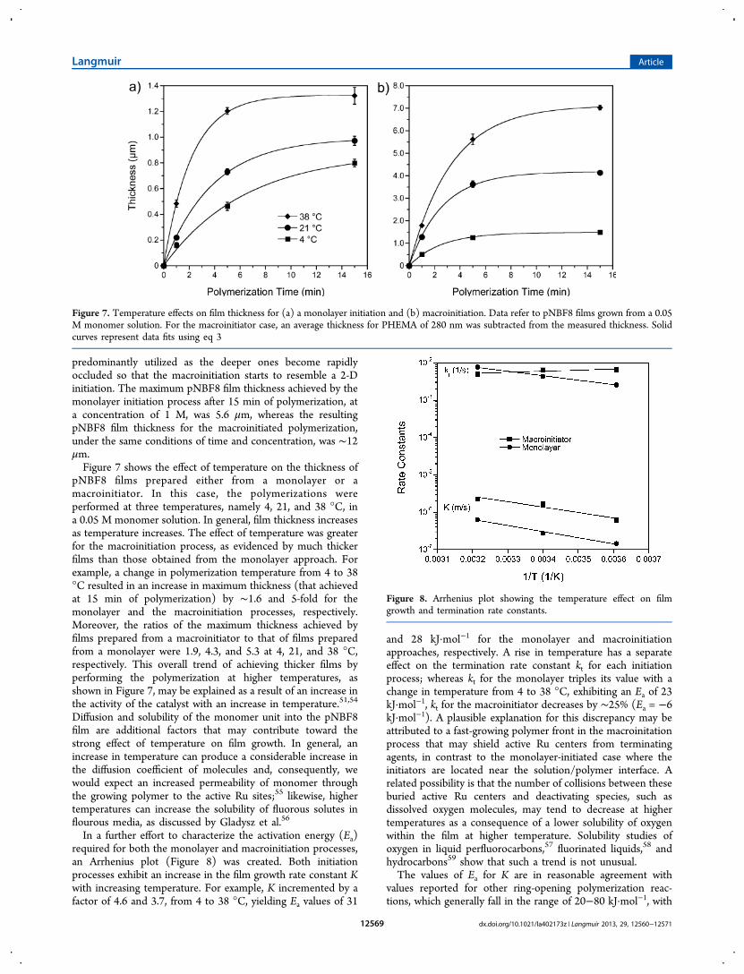
predominantly utilized as the deeper ones become rapidlyoccluded so that the macroinitiation starts to resemble a 2-Dinitiation. The maximum pNBF8 film thickness achieved by themonolayer initiation process after 15 min of polymerization, ata concentration of 1 M, was 5.6 μm, whereas the resultingpNBF8 film thickness for the macroinitiated polymerization,under the same conditions of time and concentration, was ∼12μm.Figure 7 shows the effect of temperature on the thickness of
pNBF8 films prepared either from a monolayer or amacroinitiator. In this case, the polymerizations wereperformed at three temperatures, namely 4, 21, and 38 °C, ina 0.05 M monomer solution. In general, film thickness increasesas temperature increases. The effect of temperature was greaterfor the macroinitiation process, as evidenced by much thickerfilms than those obtained from the monolayer approach. Forexample, a change in polymerization temperature from 4 to 38°C resulted in an increase in maximum thickness (that achievedat 15 min of polymerization) by ∼1.6 and 5-fold for themonolayer and the macroinitiation processes, respectively.Moreover, the ratios of the maximum thickness achieved byfilms prepared from a macroinitiator to that of films preparedfrom a monolayer were 1.9, 4.3, and 5.3 at 4, 21, and 38 °C,respectively. This overall trend of achieving thicker films byperforming the polymerization at higher temperatures, asshown in Figure 7, may be explained as a result of an increase inthe activity of the catalyst with an increase in temperature.51,54
Diffusion and solubility of the monomer unit into the pNBF8film are additional factors that may contribute toward thestrong effect of temperature on film growth. In general, anincrease in temperature can produce a considerable increase inthe diffusion coefficient of molecules and, consequently, wewould expect an increased permeability of monomer throughthe growing polymer to the active Ru sites;55 likewise, highertemperatures can increase the solubility of fluorous solutes inflourous media, as discussed by Gladysz et al.56
In a further effort to characterize the activation energy (Ea)required for both the monolayer and macroinitiation processes,an Arrhenius plot (Figure 8) was created. Both initiationprocesses exhibit an increase in the film growth rate constant Kwith increasing temperature. For example, K incremented by afactor of 4.6 and 3.7, from 4 to 38 °C, yielding Ea values of 31
and 28 kJ·mol−1 for the monolayer and macroinitiationapproaches, respectively. A rise in temperature has a separateeffect on the termination rate constant kt for each initiationprocess; whereas kt for the monolayer triples its value with achange in temperature from 4 to 38 °C, exhibiting an Ea of 23kJ·mol−1, kt for the macroinitiator decreases by ∼25% (Ea = −6kJ·mol−1). A plausible explanation for this discrepancy may beattributed to a fast-growing polymer front in the macroinitationprocess that may shield active Ru centers from terminatingagents, in contrast to the monolayer-initiated case where theinitiators are located near the solution/polymer interface. Arelated possibility is that the number of collisions between theseburied active Ru centers and deactivating species, such asdissolved oxygen molecules, may tend to decrease at highertemperatures as a consequence of a lower solubility of oxygenwithin the film at higher temperature. Solubility studies ofoxygen in liquid perfluorocarbons,57 fluorinated liquids,58 andhydrocarbons59 show that such a trend is not unusual.The values of Ea for K are in reasonable agreement with
values reported for other ring-opening polymerization reac-tions, which generally fall in the range of 20−80 kJ·mol−1, with
Figure 7. Temperature effects on film thickness for (a) a monolayer initiation and (b) macroinitiation. Data refer to pNBF8 films grown from a 0.05M monomer solution. For the macroinitiator case, an average thickness for PHEMA of 280 nm was subtracted from the measured thickness. Solidcurves represent data fits using eq 3
Figure 8. Arrhenius plot showing the temperature effect on filmgrowth and termination rate constants.
Langmuir Article
dx.doi.org/10.1021/la402173z | Langmuir 2013, 29, 12560−1257112569
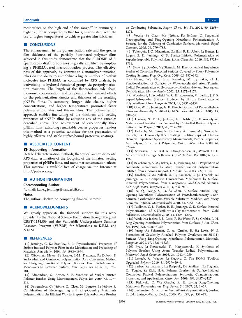
most values on the high end of this range.60 In summary, ahigher Ea for K compared to that for kt is consistent with theuse of higher temperatures to achieve greater film thickness.
■ CONCLUSIONSThe enhancement in the polymerization rate and the greaterfilm thickness of the partially fluorinated polymer filmsachieved in this study demonstrate that the SI-ROMP of 5-(perfluoro-n-alkyl)norbornenes is greatly amplified by employ-ing a PHEMA-based macroinititiation process. The effective-ness of this approach, by contrast to a monolayer initiation,relies on the ability to immobilize a higher number of catalystmolecules into PHEMA, as confirmed by XPS analysis, byderivatizing its hydroxyl functional groups via postpolymeriza-tion reactions. The length of the fluorocarbon side chain,monomer concentration, and temperature had marked effectson the polymerization kinetics and thickness of the resultingpNBFn films. In summary, longer side chains, higherconcentrations, and higher temperatures promoted fasterpolymerization rates and thicker films. The polymerizationapproach enables fine-tuning of the thickness and wettingproperties of pNBFn films by adjusting any of the variablesdescribed above. The achievement of exceptionally thickpNBFn films, exhibiting remarkable barrier properties, rendersthis method as a potential candidate for the preparation ofhighly effective and stable surface-bound protective coatings.
■ ASSOCIATED CONTENT*S Supporting InformationDetailed characterization methods, theoretical and experimentalXPS data, estimation of the footprint of the initiator, wettingproperties of pNBFn films, and monomer concentration effects.This material is available free of charge via the Internet athttp://pubs.acs.org.
■ AUTHOR INFORMATIONCorresponding Author*E-mail: [email protected] authors declare no competing financial interest.
■ ACKNOWLEDGMENTSWe greatly appreciate the financial support for this workprovided by the National Science Foundation through the grantCBET-1134509 and the Vanderbilt Undergraduate SummerResearch Program (VUSRP) for fellowships to K.E.M. andN.N.M.
■ REFERENCES(1) Jennings, G. K.; Brantley, E. L. Physicochemical Properties ofSurface-Initiated Polymer Films in the Modification and Processing ofMaterials. Adv. Mater. 2004, 16, 1983−1994.(2) Olivier, A.; Meyer, F.; Raquez, J.-M.; Damman, P.; Dubois, P.Surface-Initiated Controlled Polymerization As a Convenient Methodfor Designing Functional Polymer Brushes: From Self-AssembledMonolayers to Patterned Surfaces. Prog. Polym. Sci. 2012, 37, 157−181.(3) Edmondson, S.; Armes, S. P. Synthesis of Surface-InitiatedPolymer Brushes Using Macroinitiators. Polym. Int. 2009, 58, 307−316.(4) Detrembleur, C.; Jerome, C.; Claes, M.; Louette, P.; Jerome, R.Combination of Electrografting and Ring-Opening MetathesisPolymerization: An Efficient Way to Prepare Polynorbornene Brushes
on Conducting Substrates. Angew. Chem., Int. Ed. 2001, 40, 1268−1271.(5) Voccia, S.; Claes, M.; Jerome, R.; Jerome, C. SequentialElectrografting and Ring-Opening Metathesis Polymerization: AStrategy for the Tailoring of Conductive Surfaces. Macromol. RapidCommun. 2005, 26, 779−783.(6) Tuberquia, J. C.; Nizamidin, N.; Harl, R. R.; Albert, J.; Hunter, J.;Rogers, B. R.; Jennings, G. K. Surface-Initiated Polymerization ofSuperhydrophobic Polymethylene. J. Am. Chem. Soc. 2010, 132, 5725−5734.(7) Skale, S.; Dolecek, V.; Slemnik, M. Electrochemical ImpedanceStudies of Corrosion Protected Surfaces Covered by Epoxy PolyamideCoating Systems. Prog. Org. Coat. 2008, 62, 387−392.(8) Huang, W.; Kim, J.-B.; Bruening, M. L.; Baker, G. L.Functionalization of Surfaces by Water-Accelerated Atom-TransferRadical Polymerization of Hydroxyethyl Methacrylate and SubsequentDerivatization. Macromolecules 2002, 35, 1175−1179.(9) Woodward, I.; Schofield, W. C. E.; Roucoules, V.; Badyal, J. P. S.Super-Hydrophobic Surfaces Produced by Plasma Fluorination ofPolybutadiene Films. Langmuir 2003, 19, 3432−3438.(10) Guo, W. F.; Jennings, G. K. Directed Growth of PolymethyleneFilms on Atomically Modified Gold Surfaces. Adv. Mater. 2003, 15,588−591.(11) Hansen, N. M. L.; Jankova, K.; Hvilsted, S. FluoropolymerMaterials and Architectures Prepared by Controlled Radical Polymer-izations. Eur. Polym. J. 2007, 43, 255−293.(12) Delucchi, M.; Turri, S.; Barbucci, A.; Bassi, M.; Novelli, S.;Cerisola, G. Fluoropolyether Coatings: Relationships of Electro-chemical Impedance Spectroscopy Measurements, Barrier Properties,And Polymer Structure. J. Polym. Sci., Part B: Polym. Phys. 2002, 40,52−64.(13) Sorensen, P. A.; Kiil, S.; Dam-Johansen, K.; Weinell, C. E.Anticorrosive Coatings: A Review. J. Coat. Technol. Res. 2009, 6, 135−176.(14) Balachandra, A. M.; Baker, G. L.; Bruening, M. L. Preparation ofcomposite membranes by atom transfer radical polymerizationinitiated from a porous support. J. Membr. Sci. 2003, 227, 1−14.(15) Escobar, C. A.; Zulkifli, A. R.; Faulkner, C. J.; Trzeciak, A.;Jennings, G. K. Composite Fluorocarbon Membranes by Surface-Initiated Polymerization from Nanoporous Gold-Coated Alumina.ACS Appl. Mater. Interfaces 2011, 4, 906−915.(16) Ye, Q.; Wang, X.; Li, S.; Zhou, F. Surface-Initiated Ring-Opening Metathesis Polymerization of Pentadecafluorooctyl-5-nor-bornene-2-carboxylate from Variable Substrates Modified with StickyBiomimic Initiator. Macromolecules 2010, 43, 5554−5560.(17) Faulkner, C. J.; Fischer, R. E.; Jennings, G. K. Surface-InitiatedPolymerization of 5-(Perfluoro-n-alkyl)norbornenes from GoldSubstrates. Macromolecules 2010, 43, 1203−1209.(18) Weck, M.; Jackiw, J. J.; Rossi, R. R.; Weiss, P. S.; Grubbs, R. H.Ring-Opening Metathesis Polymerization from Surfaces. J. Am. Chem.Soc. 1999, 121, 4088−4089.(19) Juang, A.; Scherman, O. A.; Grubbs, R. H.; Lewis, N. S.Formation of Covalently Attached Polymer Overlayers on Si(111)Surfaces Using Ring-Opening Metathesis Polymerization Methods.Langmuir 2001, 17, 1321−1323.(20) Pyun, J.; Kowalewski, T.; Matyjaszewski, K. Synthesis ofPolymer Brushes Using Atom Transfer Radical Polymerization.Macromol. Rapid Commun. 2003, 24, 1043−1059.(21) Leitgeb, A.; Wappel, J.; Slugovc, C. The ROMP ToolboxUpgraded. Polymer 2010, 51, 2927−2946.(22) Barbey, R.; Lavanant, L.; Paripovic, D.; Schuwer, N.; Sugnaux,C.; Tugulu, S.; Klok, H.-A. Polymer Brushes via Surface-InitiatedControlled Radical Polymerization: Synthesis, Characterization,Properties, and Applications. Chem. Rev. 2009, 109, 5437−5527.(23) Bielawski, C. W.; Grubbs, R. H. Living Ring-OpeningMetathesis Polymerization. Prog. Polym. Sci. 2007, 32, 1−29.(24) Buchmeiser, M. R. In Surface-Initiated Polymerization I; Jordan,R., Ed.; Springer-Verlag: Berlin, 2006; Vol. 197, pp 137−171.
Langmuir Article
dx.doi.org/10.1021/la402173z | Langmuir 2013, 29, 12560−1257112570
(25) Wang, X. S.; F. Lascelles, S.; A. Jackson, R.; P. Armes, S. FacileSynthesis of Well-Defined Water-Soluble Polymers via Atom TransferRadical Polymerization in Aqueous Media at Ambient Temperature.Chem. Commun. 1999, 1817−1818.(26) Brantley, E. L.; Holmes, T. C.; Jennings, G. K. BlocklikeFluorocarbon and Hydrocarbon Copolymer Films via Surface-InitiatedATRP and Postpolymerization Reactions. Macromolecules 2005, 38,9730−9734.(27) Saha, S.; Bruening, M. L.; Baker, G. L. Facile Synthesis of ThickFilms of Poly(methyl methacrylate), Poly(styrene), and Poly(vinylpyridine) from Au Surfaces. ACS Appl. Mater. Interfaces 2011, 3,3042−3048.(28) Carlsson, L.; Malmstrom, E.; Carlmark, A. Surface-initiated ring-opening metathesis polymerisation from cellulose fibres. Polym. Chem.2012, 3, 727−733.(29) Rutenberg, I. M.; Scherman, O. A.; Grubbs, R. H.; Jiang, W.;Garfunkel, E.; Bao, Z. Synthesis of Polymer Dielectric Layers forOrganic Thin Film Transistors via Surface-Initiated Ring-OpeningMetathesis Polymerization. J. Am. Chem. Soc. 2004, 126, 4062−4063.(30) Edmondson, S.; Vo, C.-D.; Armes, S. P.; Unali, G.-F.; Weir, M.P. Layer-by-Layer Deposition of Polyelectrolyte Macroinitiators forEnhanced Initiator Density in Surface-Initiated ATRP. Langmuir 2008,24, 7208−7215.(31) Tomlinson, M. R.; Efimenko, K.; Genzer, J. Study of Kineticsand Macroinitiator Efficiency in Surface-Initiated Atom-TransferRadical Polymerization. Macromolecules 2006, 39, 9049−9056.(32) Liu, Y.; Klep, V.; Zdyrko, B.; Luzinov, I. Polymer Grafting viaATRP Initiated from Macroinitiator Synthesized on Surface. Langmuir2004, 20, 6710−6718.(33) Gabriel, S.; Jerome, R.; Jerome, C. Cathodic Electrografting ofAcrylics: From Fundamentals to Functional Coatings. Prog. Polym. Sci.2010, 35, 113−140.(34) Belanger, D.; Pinson, J. Electrografting: a Powerful Method forSurface Modification. Chem. Soc. Rev. 2011, 40, 3995−4048.(35) Jung, D.-H.; Park, I. J.; Choi, Y. K.; Lee, S.-B.; Park, H. S.; Ruhe,J. Perfluorinated Polymer Monolayers on Porous Silica for Materialswith Super Liquid Repellent Properties. Langmuir 2002, 18, 6133−6139.(36) Jordan, R.; Advincula, R.; Buchmeiser, R.; Dyer, D. J.; Fukuda,T.; Goto, A.; Matsuda, T.; Ohno, K.; Tsujii, Y.; Yamamoto, S. InSurface-Initiated Polymerization I; Springer: Berlin, 2010.(37) Perez, E.; Laval, J. P.; Bon, M.; Rico, I.; Lattes, A. Synthesis ofBicyclo[2·2·1]hept-2-enes with Mono and Disubstituted LongPerfluorinated Chains CnF2n + 1 (n = 4, 6, 8, 10) Investigation ofAssociation in Solution by 19F NMR Study of Polymerization via aMetathetic Reaction. J. Fluorine Chem. 1988, 39, 173−196.(38) Shah, R. R.; Merreceyes, D.; Husemann, M.; Rees, I.; Abbott, N.L.; Hawker, C. J.; Hedrick, J. L. Using Atom Transfer RadicalPolymerization To Amplify Monolayers of Initiators Patterned byMicrocontact Printing into Polymer Brushes for Pattern Transfer.Macromolecules 2000, 33, 597−605.(39) Kwok, A. Y.; Qiao, G. G.; Solomon, D. H. Synthetic Hydrogels3. Solvent Effects on Poly(2-hydroxyethyl Methacrylate) Networks.Polymer 2004, 45, 4017−4027.(40) Brandrup, J.; Immergut, E. H.; Grulke, E. A.; Abe, A.; Bloch, D.R. Polymer Handbook 4thth ed.; John Wiley & Sons: New York, 2003.(41) Galvin, C. J.; Genzer, J. Applications of Surface-GraftedMacromolecules Derived from Post-Polymerization ModificationReactions. Prog. Polym. Sci. 2012, 37, 871−906.(42) Briggs, D.; Seah, P. Practical Surface Analysis: Auger and X-rayPhotoelectron Spectroscopy; Wiley: New York, 1990.(43) Tesmer, J. R.; Nastasi, M. A. Handbook of Modern Ion BeamMaterials Analysis; Materials Research Society: Warrendale, PA, 1995.(44) Harada, Y.; Girolami, G. S.; Nuzzo, R. G. Catalytic Amplificationof Patterning via Surface-Confined Ring-Opening Metathesis Polymer-ization on Mixed Primer Layers Formed by Contact Printing.Langmuir 2003, 19, 5104−5114.
(45) Perova, T. S.; Vij, J. K.; Xu, H. Fourier Transform Infrared Studyof Poly(2-hydroxyethyl Methacrylate) PHEMA. Colloid Polym. Sci.1997, 275, 323−332.(46) Fukushima, H.; Seki, S.; Nishikawa, T.; Takiguchi, H.; Tamada,K.; Abe, K.; Colorado, R.; Graupe, M.; Shmakova, O. E.; Lee, T. R.Microstructure, Wettability, And Thermal Stability of SemifluorinatedSelf-Assembled Monolayers (SAMs) on Gold. J. Phys. Chem. B 2000,104, 7417−7423.(47) Brantley, E. L.; Holmes, T. C.; Jennings, G. K. Modification ofATRP Surface-Initiated Poly(hydroxyethyl Methacrylate) Films withHydrocarbon Side Chains. J. Phys. Chem. B 2004, 108, 16077−16084.(48) Berron, B.; Jennings, G. K. Loosely Packed Hydroxyl-Terminated SAMs on Gold. Langmuir 2006, 22, 7235−7240.(49) Bard, A. J.; Faulkner, L. R. Electrochemical Methods:Fundamentals and Applications; Wiley: New York, 2001.(50) Berron, B. J.; Graybill, E. P.; Jennings, G. K. Growth andstructure of surface-initiated poly(n-alkylnorbornene) films. Langmuir2007, 23, 11651−11655.(51) Bielawski, C. W.; Grubbs, R. H. Highly Efficient Ring-OpeningMetathesis Polymerization (ROMP) Using New Ruthenium CatalystsContaining N-Heterocyclic Carbene Ligands. Angew. Chem. 2000, 39,2903−2906.(52) Love, J. A.; Sanford, M. S.; Day, M. W.; Grubbs, R. H. Synthesis,Structure, and Activity of Enhanced Initiators for Olefin Metathesis. J.Am. Chem. Soc. 2003, 125, 10103−10109.(53) Slugovc, C. The Ring Opening Metathesis PolymerisationToolbox. Macromol. Rapid Commun. 2004, 25, 1283−1297.(54) Perring, M.; Bowden, N. B. Assembly of Organic Monolayers onPolydicyclopentadiene. Langmuir 2008, 24, 10480−10487.(55) Seader, J. D.; Henley, E. J. Separation Process Principles; JohnWiley & Sons, Inc.: New York, 2006.(56) Gladysz, J.; Jurisch, M. In Fluorous Chemistry; Horvath, I. T.,Ed.; Springer: Berlin, Heidelberg, 2012; Vol. 308, pp 1−23.(57) Dias, A. M. A.; Freire, M.; Coutinho, J. A. P.; Marrucho, I. M.Solubility of Oxygen in Liquid Perfluorocarbons. Fluid Phase Equilib.2004, 222−223, 325−330.(58) Costa Gomes, M. F.; Deschamps, J.; Menz, D. H. Solubility ofDioxygen in Seven Fluorinated Liquids. J. Fluorine Chem. 2004, 125,1325−1329.(59) Battino, R.; Rettich, T. R.; Tominaga, T. The Solubility ofOxygen and Ozone in Liquids. J. Phys. Chem. Ref. Data 1983, 12, 163−178.(60) Odian, G. G. Principles of Polymerization; Wiley: New York,2004.
Langmuir Article
dx.doi.org/10.1021/la402173z | Langmuir 2013, 29, 12560−1257112571