catalytic pellet reactor under uncertainty...
TRANSCRIPT
Catalytic Pellet Reactor Under Uncertainty Design
Catalytic Pellet Reactor Under Uncertainty Catalytic Pellet Reactor Under Uncertainty DesignDesign
Final Presentation at the REU meeting Chicago, IL, Tuesday, Aug. 4th, 2005.
Presenter: Celia Xue
Advisors: Pf. LinningerDr. Libin Zhang
Laboratory for Product and Process Design, Department of Chemical Engineering, University of Illinois,
Chicago, IL 60607, U.S.A.
LPPDLPPDCelia
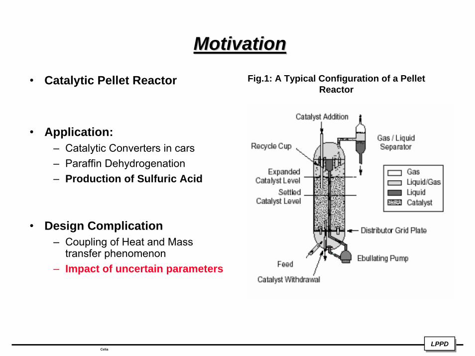
MotivationMotivationFig.1: A Typical Configuration of a Pellet
Reactor• Catalytic Pellet Reactor
• Application:– Catalytic Converters in cars– Paraffin Dehydrogenation– Production of Sulfuric Acid
• Design Complication– Coupling of Heat and Mass
transfer phenomenon– Impact of uncertain parameters
LPPDLPPDCelia
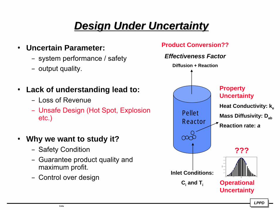
Design Under UncertaintyDesign Under UncertaintyProduct Conversion??
Effectiveness FactorDiffusion + Reaction
• Uncertain Parameter: – system performance / safety – output quality.
• Lack of understanding lead to:– Loss of Revenue– Unsafe Design (Hot Spot, Explosion
etc.)
• Why we want to study it?– Safety Condition – Guarantee product quality and
maximum profit.– Control over design
Pellet Reactor
Inlet Conditions:
Ci and Ti
0
0.0001
0.0002
0.0003
0.0004
0.0005
0.0006
80 00 90 00 10000 1 1000 12000Fb
P(Fb
)
???
Operational Uncertainty
Property UncertaintyHeat Conductivity: ke
Mass Diffusivity: Dab
Reaction rate: a
LPPDLPPDCelia
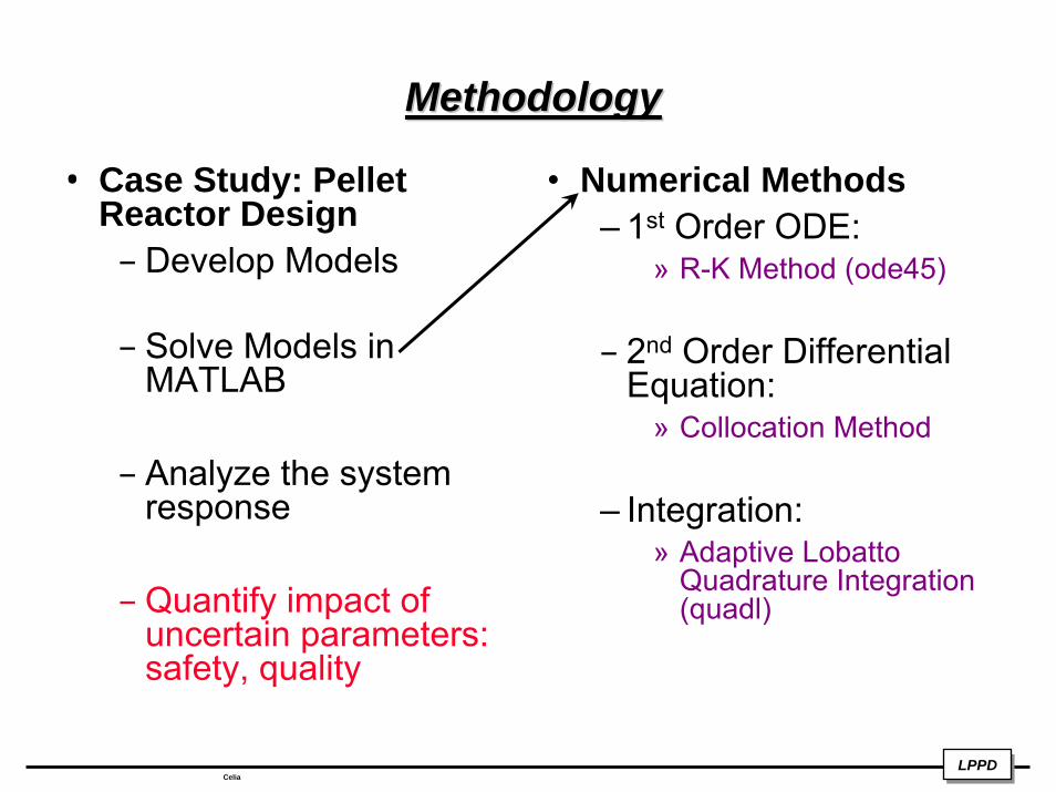
MethodologyMethodology
• Case Study: Pellet Reactor Design– Develop Models
– Solve Models in MATLAB
– Analyze the system response
– Quantify impact of uncertain parameters: safety, quality
• Numerical Methods– 1st Order ODE:
» R-K Method (ode45)
– 2nd Order Differential Equation:
» Collocation Method
– Integration: » Adaptive Lobatto
Quadrature Integration (quadl)
LPPDLPPDCelia
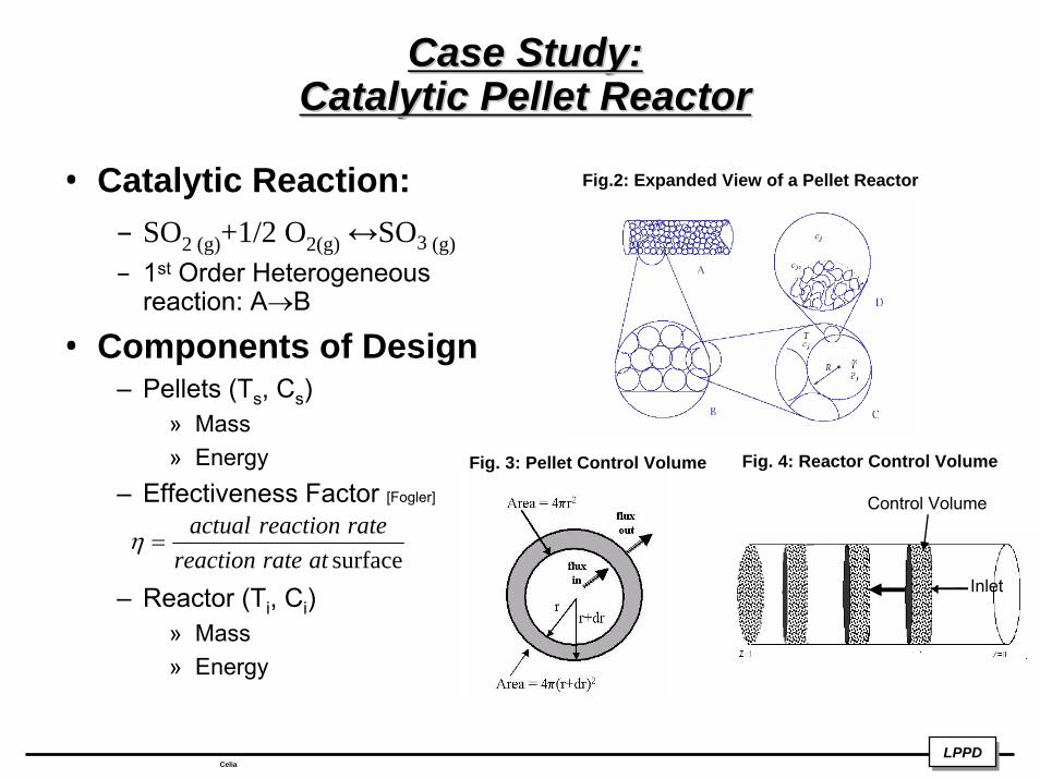
Case Study: Case Study: Catalytic Pellet ReactorCatalytic Pellet Reactor
• Catalytic Reaction:– SO2 (g)+1/2 O2(g) ↔SO3 (g)– 1st Order Heterogeneous
reaction: A→B
• Components of Design– Pellets (Ts, Cs)
» Mass» Energy
– Effectiveness Factor [Fogler]
– Reactor (Ti, Ci)» Mass» Energy
surfaceatratereactionratereactionactual
=η
Fig. 3: Pellet Control Volume Fig. 4: Reactor Control Volume
Fig.2: Expanded View of a Pellet Reactor
Control Volume
Inlet
LPPDLPPDCelia
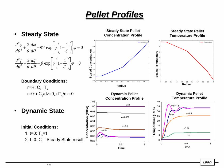
Pellet Profiles Pellet Profiles
• Steady State
Boundary Conditions:r=R: Cs, Ts
r=0: dCs/dz=0, dTs/dz=0
• Dynamic State
Initial Conditions:1. t=0: To=12. t=0: Co =Steady State result
Steady State Pellet Temperature Profile
Steady State Pellet Concentration Profile
22
2
2 1exp 1 0d dd dϕ ϕ γ ϕθ θ θ ζ
⎡ ⎤⎛ ⎞+ −Φ − =⎢ ⎥⎜ ⎟
⎝ ⎠⎣ ⎦2
2
2 1exp 1 0d dd dζ ζ β γ ϕθ θ θ ζ
⎡ ⎤⎛ ⎞+ − − =⎢ ⎥⎜ ⎟
⎝ ⎠⎣ ⎦
0 0.1 0.2 0.3 0.4 0.5 0.6 0.7 0.8 0.9 10.86
0.88
0.90
0.92
0.94
0.96
0.98
1.00
di
Concentration
0 0.1 0.2 0.3 0.4 0.5 0.6 0.7 0.8 0.9 10
5
10
15
20
25
30
35
p
Temperature
0.86
0.88
0.90
0.92
0.94
0.96
0.98
1.00
1.02
0 0.5 1Time
Con
cent
ratio
n (C
/Co)
r=1
r=0.887
r=0.5
r=0.113
r=00
5
10
15
20
25
30
35
40
0 0.5 1Time
Tem
pera
ture
(T/T
o)
r=0
r=0.113
r=0.5
r=0.88
r=1
Dynamic Pellet Concentration Profile
Dynamic Pellet Temperature Profile
Radius Radius
Scal
ed C
once
ntra
tion
Scal
ed T
empe
ratu
re
LPPDLPPDCelia
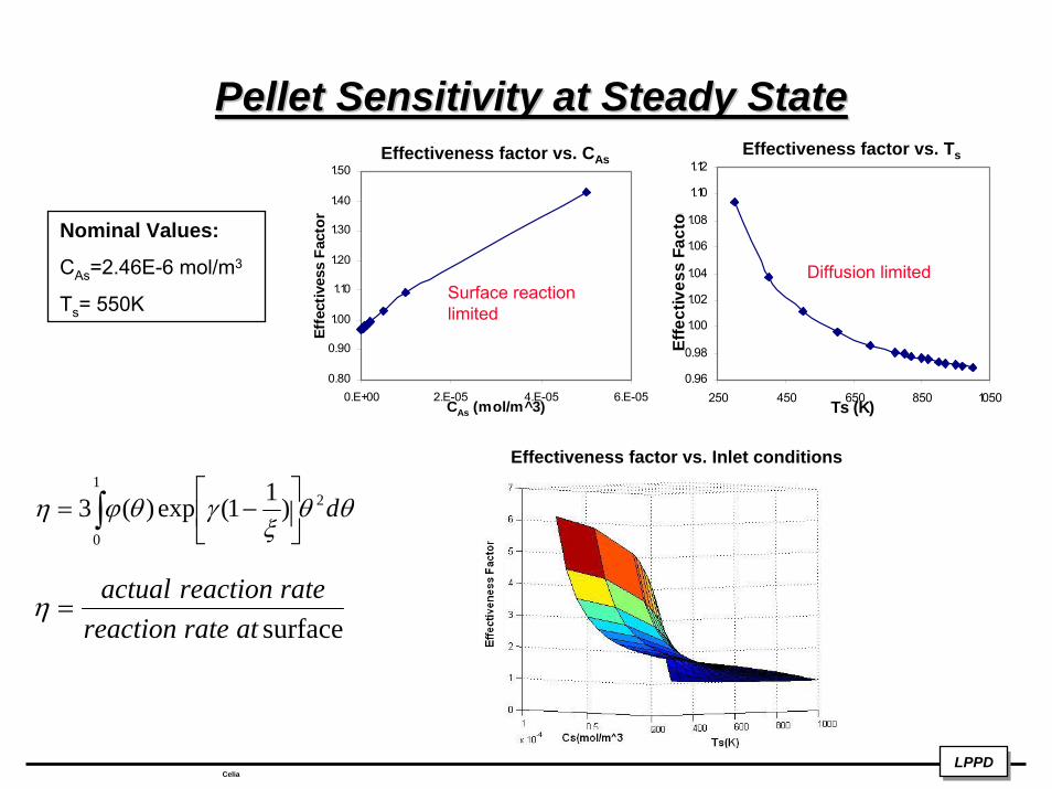
Pellet Sensitivity at Steady StatePellet Sensitivity at Steady State
0.80
0.90
1.00
1.10
1.20
1.30
1.40
1.50
0.E+00 2.E-05 4.E-05 6.E-05CAs (mol/m^3)
Effe
ctiv
ess
Fact
or
0.96
0.98
1.00
1.02
1.04
1.06
1.08
1.10
1.12
250 450 650 850 1050Ts (K)
Effe
ctiv
ess
Fact
or
surfaceatratereactionratereactionactual
=η
Effectiveness factor vs. TsEffectiveness factor vs. CAs
Diffusion limitedSurface reaction limited
Nominal Values:
CAs=2.46E-6 mol/m3
Ts= 550K
LPPDLPPDCelia
Effectiveness factor vs. Inlet conditions
θθξ
γθϕη d21
0
)11(exp)(3∫ ⎥⎦
⎤⎢⎣
⎡−=
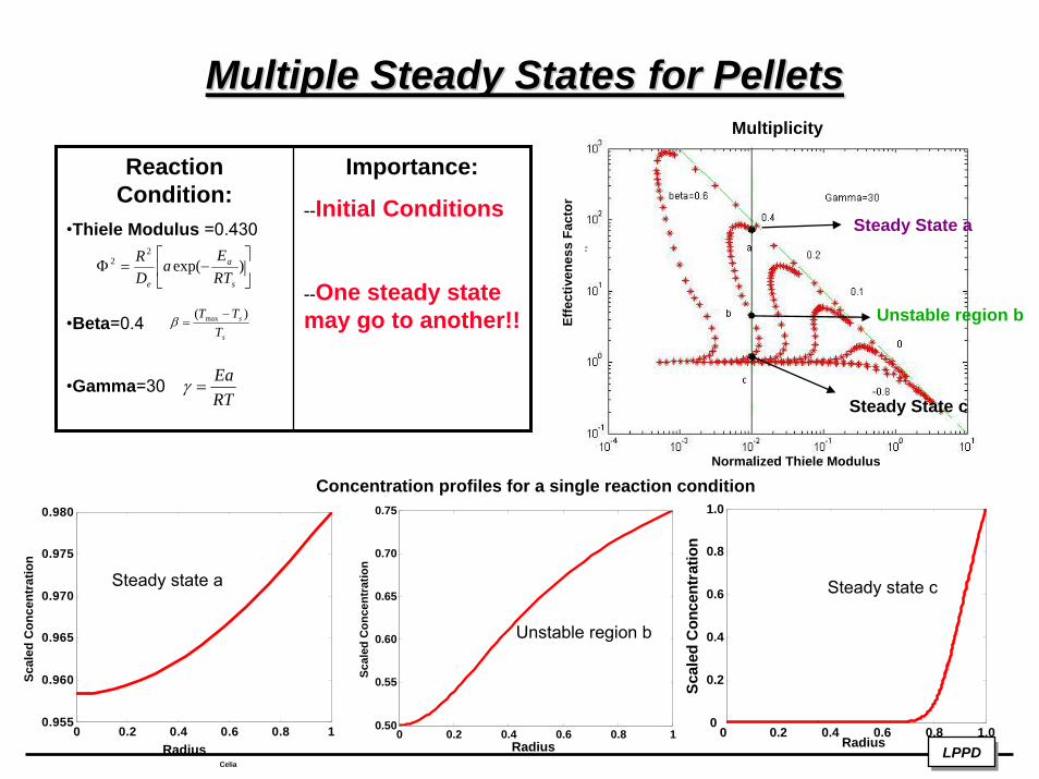
Multiple Steady States for PelletsMultiple Steady States for Pellets
LPPDLPPDCelia
0 0.2 0.4 0.6 0.8 10.50
0.55
0.60
0.65
0.70
0.75
Scal
ed C
once
ntra
tion
0 0.2 0.4 0.6 0.8 1.00
0.2
0.4
0.6
0.8
1.0
Scal
ed C
once
ntra
tion
0 0.2 0.4 0.6 0.8 10.955
0.960
0.965
0.970
0.975
0.980
Scal
ed C
once
ntra
tion
Reaction Condition:
•Thiele Modulus =0.430
•Beta=0.4
•Gamma=30
Importance:
--Initial Conditions
--One steady state may go to another!!
⎥⎦
⎤⎢⎣
⎡−=Φ )exp(
22
s
a
e RTE
aDR
s
s
TTT )( max −=β
RTEa
=γ
Steady state a
Unstable region b
Steady state c
Normalized Thiele Modulus
Radius Radius Radius
Concentration profiles for a single reaction condition
Multiplicity
Effe
ctiv
enes
s Fa
ctor
Steady State a
Unstable region b
Steady State c
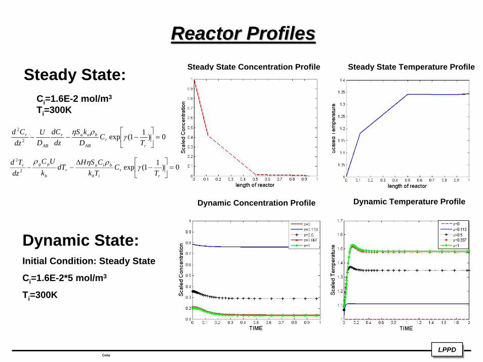
Reactor ProfilesReactor ProfilesSteady State Concentration Profile Steady State Temperature ProfileSteady State:
Ci=1.6E-2 mol/m3
Ti=300K
0)11(exp2
2
=⎥⎦
⎤⎢⎣
⎡−−−
rr
AB
boar
AB
r
TC
DkS
dzdC
DU
dzCd
γρη
0)11(exp2
2
=⎥⎦
⎤⎢⎣
⎡−
∆−−
rr
ib
biar
b
pgr
TC
TkCSH
dTk
UCdz
Tdγ
ρηρ
Dynamic Temperature ProfileDynamic Concentration Profile
Dynamic State:Initial Condition: Steady State
Ci=1.6E-2*5 mol/m3
Ti=300K
LPPDLPPDCelia
Reactor Safety: HotspotReactor Safety: Hotspot
LPPDLPPDCelia
0 0.2 0.4 0.6 0.8 11
1.05
1.10
1.15
1.20
1.25
length of reactor
Scal
ed T
empe
ratu
re
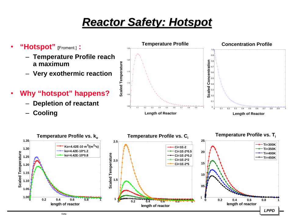
Ti=300KTi=350KTi=400KTi=450K
0 0.2 0.4 0.6 0.8 11.00
1.05
1.10
1.15
1.20
1.25
1.30
1.35
length of reactor
Scal
ed T
empe
ratu
re
Ko=4.42E-10 m3/(m2*s)ko=4.42E-10*1.2ko=4.42E-10*0.8
0 0.2 0.4 0.6 0.8 11
1.5
2.0
2.5
length of reactor
Scal
ed T
empe
ratu
re
Ci=1E-2Ci=1E-2*0.5Ci=1E-2*0.2Ci=1E-2*2Ci=1E-2*5
• “Hotspot” [Froment.] :– Temperature Profile reach
a maximum– Very exothermic reaction
• Why “hotspot” happens?– Depletion of reactant– Cooling
0 0.1 0.2 0.3 0.4 0.5 0.6 0.7 0.8 0.9 11.00
1.05
1.10
1.15
1.20
1.25
0 0.1 0.2 0.3 0.4 0.5 0.6 0.7 0.8 0.9 10
0.1
0.2
0.3
0.4
0.5
0.6
0.7
0.8
0.9
1.0
Temperature Profile Concentration Profile
Temperature Profile vs. CiTemperature Profile vs. Ti
Scal
ed T
empe
ratu
re
Scal
ed C
once
ntra
tion
Temperature Profile vs. ko
Length of Reactor Length of Reactor
Reactor Safety: MultiplicityReactor Safety: Multiplicity
LPPDLPPDCelia
0 0.1 0.2 0.3 0.4 0.5 0.6 0.70
5
10
15
20
25
Time
Sca
led
Tem
pera
ture
Steady State a
Unstable region b
Steady State c
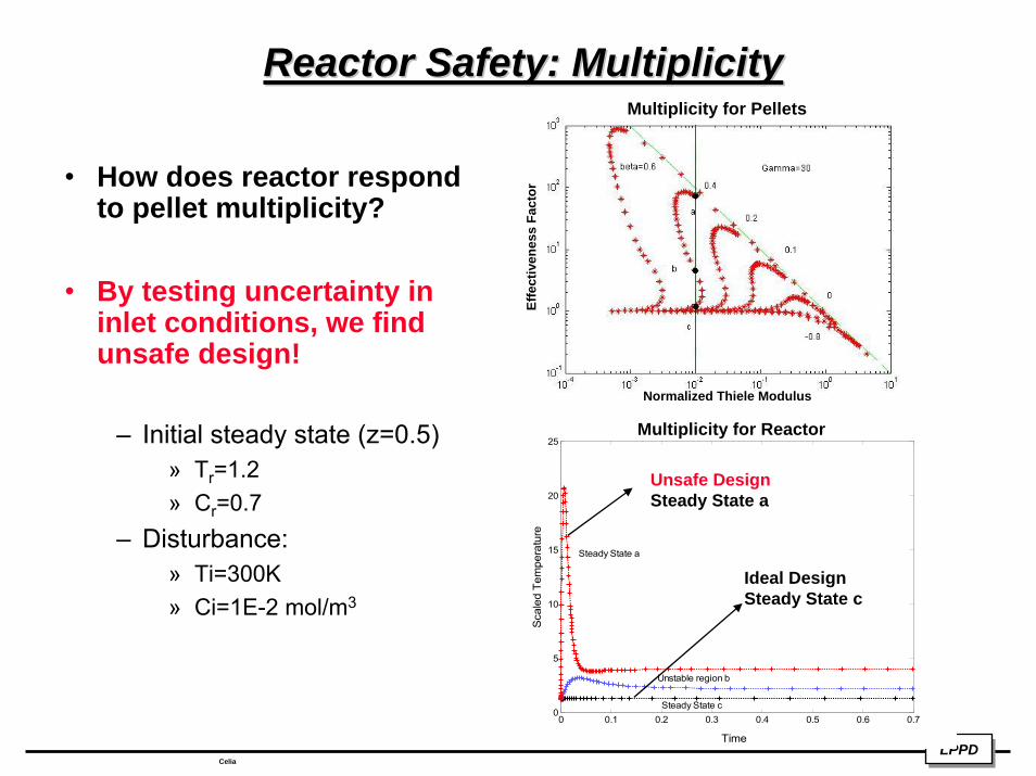
Ideal Design Steady State c
Unsafe Design Steady State a
Normalized Thiele Modulus
Multiplicity for Pellets
Multiplicity for Reactor
• How does reactor respond to pellet multiplicity?
• By testing uncertainty in inlet conditions, we find unsafe design!
– Initial steady state (z=0.5)» Tr=1.2» Cr=0.7
– Disturbance: » Ti=300K» Ci=1E-2 mol/m3
Effe
ctiv
enes
s Fa
ctor
ConclusionConclusion
– Pellet steady/dynamic state profiles
– Multiplicity in pellets
– Reactor steady/dynamic state profiles
– Reactor “hotspot”
– Uncertainty analysis helps to prevent unsafe design!
LPPDLPPDCelia
ReferencesReferences
• 1. Malcom, A,; Linninger, A.A; “Integrating Design ad Control: Dynamic Analysis of Flexible Operation.”http://viena.che.edu/research/designcontrol/DesigControl.pdf. [June 8, 2005.]
• 2. Fogler H. Scott, Elements of Chemical Reaction Engineering, 3rd Ed., Prentice Hall PTR, 1999.
• 3. Froment Gilbert F. and Bischoff Kenneth B. Chemical Reactor Analysis and Design, 2nd Ed. John Wiley & Sons, Inc., Canada, 1979.
• 4. Catalytic Pellet Reactor. http://jbrwww.che.wisc.edu/~jbraw/chemreacfun/ ch7/slides-masswrxn.pdf. [July 11th, 2005]
• 5. Perkins Victor and Gomez Javier Cruz. Assessment of Electricity Generation to 2011 Using Low Sulfur Fuel Oil in Mexico. http://www.iaee.org/documents/AssessmentofElectricityGenerationto2011UsingLowSulfurFuelOilinMexicoVictorBazC3A1nPerkinsJavierCruzGC3B3mez.pdf. [July 11th, 2005]
LPPDLPPDCelia
AcknowledgementAcknowledgement
• NSF DMI 0328134 REU Supplement (Linninger) PI
LPPDLPPDCelia