catalytic conversion wood syngas to synthetic aviation turbine fuels over
DESCRIPTION
Catalytic Conversion Wood Syngas to Synthetic Aviation Turbine Fuels OverTRANSCRIPT
Bioresource Technology 127 (2013) 281–290
Contents lists available at SciVerse ScienceDirect
Bioresource Technology
journal homepage: www.elsevier .com/locate /bior tech
Catalytic conversion wood syngas to synthetic aviation turbine fuels overa multifunctional catalyst
Qiangu Yan a, Fei Yu a,⇑, Jian Liu b, Jason Street a, Jinsen Gao b, Zhiyong Cai c, Jilei Zhang d
a Department of Agricultural and Biological Engineering, Mississippi State University, Mississippi State, MS, USAb State Key Laboratory of Heavy Oil, China University of Petroleum, Beijing 102249, PR Chinac USDA Forest Service, Forest Products Laboratory, Madison, WI, USAd Department of Forest Products, Mississippi State University, Mississippi State, MS, USA
h i g h l i g h t s
" A continuous process was developedto make synthetic aviation turbinefuels from biomass.
" The process involved gasification,syngas cleaning, and Fischer–Tropsch synthesis.
" Synthetic aviation turbine fuels wereproduced from syngas over a multi-functional catalyst.
0960-8524/$ - see front matter � 2012 Elsevier Ltd. Ahttp://dx.doi.org/10.1016/j.biortech.2012.09.069
⇑ Corresponding author.E-mail address: [email protected] (F. Yu).
g r a p h i c a l a b s t r a c t
Synthetic aviation turbine fuels were produced from wood syngas over a multi-functional catalyst.
a r t i c l e i n f o
Article history:Received 14 July 2012Received in revised form 17 September2012Accepted 21 September 2012Available online 29 September 2012
Keywords:Wood syngasSynthetic aviation turbine fuels (SATFs)GasificationSyngas cleaningMulti-functional catalyst
a b s t r a c t
A continuous process involving gasification, syngas cleaning, and Fischer–Tropsch (FT) synthesis wasdeveloped to efficiently produce synthetic aviation turbine fuels (SATFs). Oak-tree wood chips were firstgasified to syngas over a commercial pilot plant downdraft gasifier. The raw wood syngas contains about47% N2, 21% CO, 18% H2, 12% CO2, 2% CH4 and trace amounts of impurities. A purification reaction systemwas designed to remove the impurities in the syngas such as moisture, oxygen, sulfur, ammonia, and tar.The purified syngas meets the requirements for catalytic conversion to liquid fuels. A multi-functionalcatalyst was developed and tested for the catalytic conversion of wood syngas to SATFs. It was demon-strated that liquid fuels similar to commercial aviation turbine fuels (Jet A) was successfully synthesizedfrom bio-syngas.
� 2012 Elsevier Ltd. All rights reserved.
1. Introduction
Biomass-derived fuels are becoming more popular due to therising costs of fossil fuels as well as concerns of national securityand the national economy. A wide range of fuels and chemicalscan be produced from biomass, including gasoline, diesel, heatingfuel, jet fuel, synthetic natural gas, and oxygenates (Huang et al.,2012; Che et al., 2012). Aviation turbine fuels (ATFs) are a complexmixture of C8–C17 hydrocarbons, which include paraffins, iso-paraffins, aromatics and naphthenes (Huber et al., 2006). Theyare currently produced from the kerosene fraction of petroleum
ll rights reserved.
distillation and hydro-processing of heavier fraction of the petro-leum (Wright et al., 2008). In the past decades, many efforts havebeen performed on production of ATF from shale, coal, and tarsands (Daggett et al., 2008). Shale-derived JP-4 has been testedand demonstrated using aviation engines, and no harmful conse-quences were found (Edwards, 2003). No negative impact wasfound on engine operation when using syngas-based Jet fuels(Moses et al., 1997). Since almost all the ATFs are from the non-renewable petroleum, it is necessary to find a sustainable routefor producing SATFs. The most highly developed and technicallyproven route for producing alternative fuels from lignocellulosicbiomass involves the gasification process. Syngas is produced,cleaned, and then catalytically converted via Fischer–Tropsch syn-thesis (FTS) or CO hydrogenation (alcohol synthesis). The products
282 Q. Yan et al. / Bioresource Technology 127 (2013) 281–290
are then upgraded to sequester the desired products (Leckel,2009a).
Currently, FT-based catalysts including iron and cobalt catalystshave been used to produce long-chain paraffins from syngas. Theseproducts undergo hydrotreating and/or the hydrocracking processto upgrade these long-chain paraffins to the desired range of ATFsor jet fuels. In order to meet the requirement of the freezing point(�40 to �47 �C) and other important specifications of commercialATF (Jet A) and military ATF (JP-8), aromatics and/or naphthenesshould be increased in the FTS-derived ATF fraction (Huber et al.,2006; Dupain et al., 2005). Multiple processing steps of FTS liquidsare required to reach these specifications of Jet A and JP-8 (Huberet al., 2006; Leckel, 2009a and Forest and Muzzell, 2005). However,too many processing steps will increase the cost of the product anddecrease the overall efficiency of the process. Therefore, it is signif-icant to explore simple processes over a multi-functional catalystfor the creation of SATFs through FTS (Forest and Muzzell, 2005).Many studies have been carried out to synthesize liquid fuels usinghigh quality syngas (mainly CO and H2) with a low nitrogen com-position (Yan and Yu, 2012), which is mainly derived from naturalgas or coal. There are a limited number of publications using nitro-gen-rich, high CO2 syngas to produce hydrocarbons (Yan and Yu,2012). The existing downdraft gasifier at Mississippi State Univer-sity is producing syngas from biomass (known as producer gas).Currently, the producer gas contains about 18% hydrogen, 21%CO, 12% CO2, 2% CH4 and 47% N2 (Yan and Yu, 2012). The nitrogenand carbon dioxide contents are too high for economic hydrocar-bon synthesis using existing catalyst technologies. Developing highactivity and high stability catalysts is essential for better overallperformance when using producer gas. In this study, a continuousprocess including catalyst preparation, gasification, syngas clean-ing, and FTS was developed to demonstrate biomass to liquid(BTL) fuel technology. A multi-functional catalyst was designedand tested for the catalytic conversion of producer gas derivedfrom wood to form SATFs. The activity, selectivity, stability, andlife-time of the catalyst were evaluated. The liquid product wasanalyzed and compared to fuel Jet A.
2. Experimental
2.1. Preparation of syngas from wood chips
Oak-tree wood chips were used as the feedstock for the gasifi-cation process. Their moisture content was analyzed with anOHAUS MB200 balance (Certified Scale, Inc., Menomonee Falls,WI). The sample weight was measured at room temperature. Thesample was heated to and held at 160 �C until a constant valuewas obtained (changes < 0.01 g in 60 s). The percent of weight losswas regarded as the moisture content. Wood chips with a moisturecontent of 8.3–10.8% were used in this research for material andenergy balance analysis.
The producer gas composition was analyzed with an Agilent6890N GC (Santa Clara, CA), with a TCD detector, and argon wasused as the carrier gas. The process temperatures were obtainedfrom the host computer, which acquired the data from thermocou-ples. The volume concentrations of main syngas components weremonitored online by a portable gas analyzer (7900P4C, NOVA Ana-lytical Systems, Inc., Niagara Falls, NY).
The pilot-plant scale downdraft gasifier, BioMax 25, waspurchased from Community Power Corporation (Littleton, CO).The automatic gasification system used a host computer to controlthe gasification process. Its main components included the feedingsystem, the gasifier, the heat exchanger and the filters. There weremultiple thermocouples and pressure transducers installed in thesystem to monitor the running of the gasification system. The
producer gas flow rate was set at 65 Nm3/h. The computer programwould adjust the air injection rate and wood chip feeding rateaccording to the setting producer gas flow rate.
An auger feeding system was installed with the gasifier. Whenthe fuel level in the gasifier fell below the set-point, the motor ofthe feeder would be activated. The gasifier was designed with fivelevels of air injection loops, and each loop had six injection pointsinto the gasifier. This ensured that the air was distributed into thegasifier evenly at the same level. The amount and rate of air injec-tion were controlled by the computer and varied according to thetemperatures inside the gasifier.
The heat exchanger cooled the producer gas from 500–700 �C toabout 110 �C. This system used ambient air to cool the producergas. The producer gas then went through parallel bag filters to re-move fine particles. After filtration, the producer gas then wentthrough a filter with activated carbon to remove tars. The effluentproducer gas contained about 47% N2, 21% CO, 18% H2, 12% CO2, 2%CH4, some water vapor and trace amount of other gases. The coolsyngas was then compressed to a storage tank or sent to a burner.Mass balance and carbon balance were performed based on woodchip feeding rate, inlet air flow rate, outlet gas flows, gas composi-tion analysis, solid char weight and composition analysis. Theashes and tars that were trapped inside the gasification systemwere neglected when calculating the material.
2.2. Cleaning and compression of wood syngas
The producer gas was first compressed to approximately0.31 MPa. After compression, a water scrubber and gas dryingapparatus were assembled to scrub the producer gas. Two 25-gal-lon 304 stainless steel (SS) wide mouth tanks were connected forthe water scrubber. The first tank was outfitted with 13 SS exhaustmufflers with a filtration rating of 50 l. These mufflers were usedto create the maximum amount of gas bubbles so that the utmostpossible surface area of producer gas could come in contact withthe water, and contaminants, e.g., ammonia, could be scrubbedby dissolving in the water. After the water scrubber process, thegasifier syngas was flowed through another 25-gallon tank whichcontained 36 kg of silica gel desiccant to remove moisture in theproducer gas. Finally, the producer gas was compressed to approx-imately 13.8 MPa using a 2-stage pneumatic air pump obtainedfrom Hydraulics International (Chatsworth, CA).
2.3. Deep purification of the compressed producer gas
A syngas purification process was designed after indentifyingthe possible poisoning or negative components for the FTS process,e.g., moisture, oxygen, sulfur, ammonia and tar. The catalysts andadsorbents were selected from alumina-supported metal catalysts,molsieve 13X, active carbon, silica gel and other high surface areamaterials. These catalysts and adsorbents were loaded into reac-tors in series. The reactor system was built with controlling param-eters of temperature, pressure, and flow rate. The pilot-plant scalecleaning unit is built in the Pace Seed Laboratory of MississippiState University. The cleaned syngas should meet the basicrequirements for the following step of catalytic conversion to li-quid fuels and chemicals. These specifications include a sulfur con-tent (H2 S + COS) of less than 10 ppb, and ammonia content (NH3)of less than 1 ppm, and an oxygen content of less than 1 ppm (Yanand Yu, 2012).
2.4. Preparation of Fe promoted K–Co–Mo–c-Alumina catalysts
c-Alumina (surface area, 246 m2/g, pore volume, 1.15 mL/g)was used as the support for the preparation of Fe promoted K–Co–Mo–c-Alumina catalysts. The weight percent of Mo, Co, K and
Q. Yan et al. / Bioresource Technology 127 (2013) 281–290 283
Fe was specified with the corresponding catalyst. Ammonium hep-tamolybdate, cobalt nitrate, iron nitrate, and potassium carbonate(all are from Sigma–Aldrich Company) were used as precursors forMo, Co, Fe, and K, respectively.
The catalyst samples were prepared by an aqueous incipient-wetness impregnation technique. The alumina pellets were firstground to 20–50 mesh before impregnation. The required amountof ammonium heptamolybdate was dissolved in water. Then,impregnation was done at 80 �C, dried at 120 �C for 4 h, and thencalcined at 350 �C for 2 h at a heating rate of 5 �C/min. Next, the re-quired amount of cobalt nitrate (aqueous solution) was impreg-nated at 80 �C over the Mo/c-Al2O3, dried at 120 �C for 4 h, andcalcined at 350 �C for 2 h at a heating rate of 5 �C/min. Then, sim-ilarly, the required amount of iron nitrate (aqueous solution) wasimpregnated over the Co/Mo/c-Al2O3 material at 80 �C, dried at120 �C for 4 h, and calcined at 350 �C for 2 h at a heating rate of5 �C/min. Finally, potassium carbonate was dissolved in waterand impregnated with the Fe/Co/Mo/c-Al2O3 material, dried at120 �C for 4 h, and calcined at 400 �C for 5 h. Metal loadings ofthe catalyst sample were 5 wt.% molybdenum, 3 wt.% cobalt,5 wt.% iron, and 3 wt.% potassium.
2.5. Catalytic reaction
The synthesis gas conversion reaction was carried out in a con-tinuous flow fixed-bed reactor system. Three (3) grams of the cat-alyst was loaded to the reactor. The system was first purged by ahelium flow for 30 min, followed by pre-reducing stage with a syn-gas mixture at 400 �C for 8 h, then producer gas was fed into thesystem until reaching the desired pressure by slowly adjustingthe system to the desired temperature. The reaction was operatedunder the following conditions: 250–350 �C, a gas hourly spacevelocity (GHSV) of 500–5,000 h�1 and a pressure of 3.14–8.62 MPa. Mass balance and carbon balance were performed basedon inlet/outlet flows, gas composition analysis and liquid productweight and composition.
2.6. Analysis of gas and liquid products using GC and GC/MS
The analysis of gas phase product has been carried out with anon-line Agilent 7890 gas chromatograph provided with two ther-mal conductivity detectors (TCD) and a flame ionization detector(FID). Helium and nitrogen were used as the carrier gases.
Liquid products were collected using a condenser kept at �3 �C.Liquid samples were analyzed using an Agilent 7683B Series Injec-tor coupled to an Agilent 6890 Series gas chromatograph systemand a 5973 Mass Selective Detector, i.e., a quadrupole type GC–MS system, as well as a FID detector. An Agilent DB-WAXetr(50 m � 0.32 mm I.D., 1.0 lm) capillary column was used. A con-stant column flow of 1 mL/min (24 cm3/s) helium was applied.The injector was kept at 250 �C. Samples were injected (1 lL) witha split ratio of 100:1. The temperature-programmed separationstarted at 40 �C for 5 min, and then the temperature was increasedat a rate of 10 �C/min to 250 �C for 10 min. The FID detector workedat a temperature of 250 �C with helium makeup gas at 30 mL/min.For the MS, the transfer line and EI source temperature were 250and 200 �C. Quadrupole conditions involved an electron energy of70 eV and an emission current of 150 lA. The syncrude sampleswere dried using sodium sulfate and subjected to an engine knocktest (ASTM D2699; D2700), API gravity test, distillation range test(ASTM D86) and Reid vapor pressure test (ASTM 5191). The dis-tilled syncrude samples with a boiling point between 110 and310 �C were collected and analyzed. The distillation column andprocedure which was used are described in ASTM’s standard testmethod D2892. A commercial Jet A sample was also analyzed tocompare to the liquid samples derived from the producer gas.
2.7. Detailed hydrocarbon analysis (DHA) of liquid hydrocarbons
Detailed hydrocarbon analysis (DHA) was performed over a Per-kin Elmer Clarus 680 GC with a FID detector using the PIANO meth-od. PIANO describes the method for determining the amount ofparaffins (P), iso-paraffins (I), aromatics (A), naphthenes (N), andolefins (O) within a sample. A liquid sample with a volume of1 lL was injected into a 100-meter GC column with about 200:1split ratio. A flame ionization detector and retention time librarywas used to identify compounds with a carbon number up to 14.This method is based on ASTM test method D 5134–92 but usesa 100-meter capillary column instead of a 50-meter column. ThePIANO method is mainly used for gasoline-type samples, whichis why it is limited to compounds with carbon numbers less than14. Any C15 compounds or heavier were reported as unknowncompounds. The initial temperature of the GC injector was set at200 �C and held at this temperature for 43.15 min. The sampleinjector of the GC was heated to 450 �C at 100 �C/min and held atthis temperature throughout the end of the test. A DHA analyticalcolumn (100 m � 0.25 lm I.D.) was used to separate sample com-ponents. Hydrogen was used as a carrier gas with a flow rate of100 mL/min. The initial oven temperature was held at 35 �C for5 min, heated to 50 �C at 10 �C/min and held for 21.5 min. Then,the oven temperature was ramped to 150 �C with a heating rateof 3 �C/min and kept at 150 �C for 4.67 min. The FID detector tem-perature was 250 �C with a hydrogen flow rate of 42 mL/min andan air flow rate of 450 mL/min.
3. Results and discussion
3.1. Design of multifunctional catalysts for jet fuel synthesis from woodderived syngas
Paraffins, iso-paraffins, aromatics, and naphthenes are the mainhydrocarbon components in jet fuel, while straight chain paraffinsand/or olefins are the main products over iron and cobalt-based FTcatalysts (Leckel, 2009a,b). Multiple processing steps are usuallyfollowed after FTS to reach these specifications of Jet fuel (Huberet al., 2006). However, too many processing steps will increasethe cost of the product and decrease the overall efficiency of theprocess. Therefore, to explore fewer steps for synthesizing ATFvia FTS that meets all these specifications, new catalysts areneeded to produce the desired range of ATFs or jet fuels from syn-gas. One of the alternatives to improve the selectivity and qualitylimitations of the FT process is to use hybrid or composite catalystswhich comprise a FT base catalyst and a co-catalyst containing theappropriate functionality to increase the yield and selectivity of thedesired products. The combination of an iron-based FT catalyst dis-playing high selectivity to olefins and oxygenates with ZSM-5 orHY zeolites (Botes, 2005; Yan et al., 2008) results in an enhancedgasoline selectivity and an increased concentration of high-octanebranched and aromatic hydrocarbons by promoting oligomeriza-tion, cracking, isomerization, and aromatization reactions on thezeolite acid sites. Another approach is to convert syngas to alcoholsover an alcohol synthesis catalyst, and alcohols subsequently con-vert to hydrocarbons over solid acid catalysts like ZSM-5 (Yanet al., 2008).
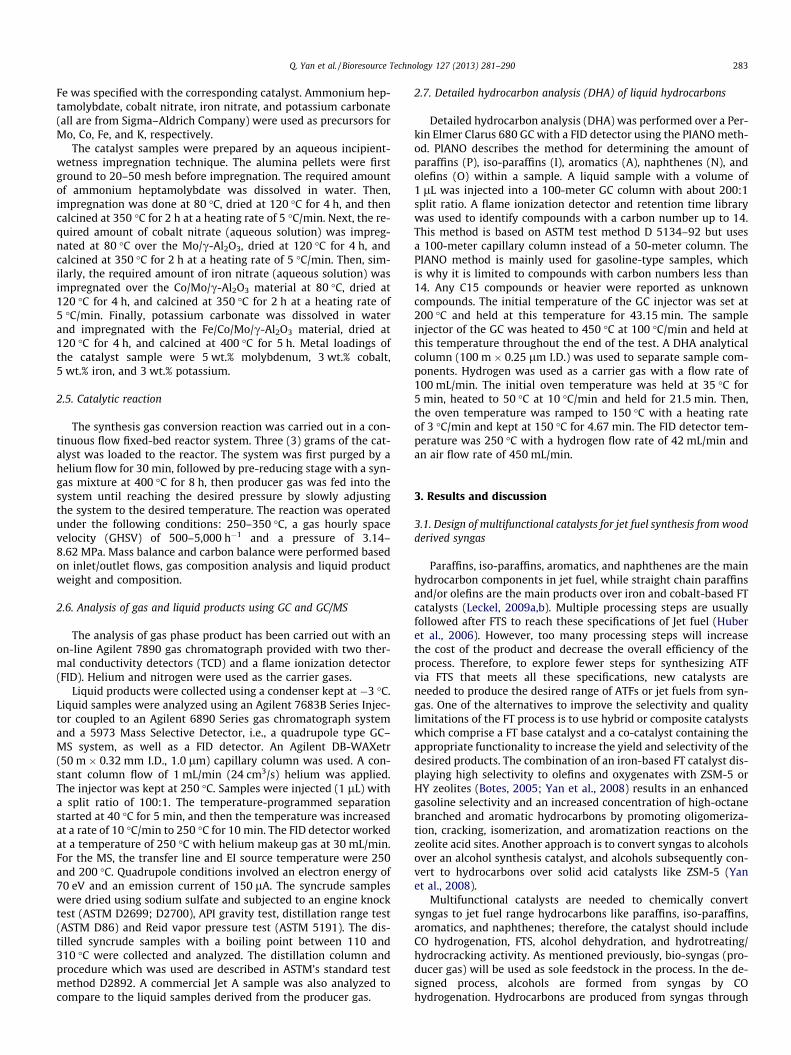
Multifunctional catalysts are needed to chemically convertsyngas to jet fuel range hydrocarbons like paraffins, iso-paraffins,aromatics, and naphthenes; therefore, the catalyst should includeCO hydrogenation, FTS, alcohol dehydration, and hydrotreating/hydrocracking activity. As mentioned previously, bio-syngas (pro-ducer gas) will be used as sole feedstock in the process. In the de-signed process, alcohols are formed from syngas by COhydrogenation. Hydrocarbons are produced from syngas through
Scheme 1. Illustration of the reactions of syngas to synthetic aviation turbine fuelsover the K–Co–Mo–c-Alumina catalyst.
284 Q. Yan et al. / Bioresource Technology 127 (2013) 281–290
alcohol dehydration and/or the FTS process over heterogeneous cat-alysts. The designed catalyst has functions of CO hydrogenation foralcohol formation, FTS for paraffin production, and alcohol dehydra-tion for producing iso-paraffins, aromatics, naphthenes fromalcohols. The isomerization function is also needed since branchedparaffins are the favored component for jet fuels, while FTS and alco-hol synthesis processes are principally used for producing linearhydrocarbon molecules (Gujar et al., 2009). Branched paraffins, aro-matics, naphthenes and/or iso-alcohols are produced from their lin-ear counterparts by the isomerization process.
Alcohols are synthesized from syngas through the CO hydroge-nation process. Various catalyst systems, such as modified Cu/ZnO,modified MoS2, and modified Fe or Co FT catalysts, have been foundto produce higher alcohols from syngas (Freerks and Muzzell,2004). Cobalt-promoted Mo based catalysts have been extensivelyused in the hydrotreating process (Davis, 2005), and it was also re-ported Co–Mo based bimetallic catalysts were active to producemixed higher alcohols from syngas (Ancheyta-JuaArez et al.,1999). C1–C7 mixture alcohols were produced from syngas overCo–Mo based catalysts (Bian et al., 1999).
Only Fe, Co, Ni and Ru metals have sufficiently high activities forthe FTS process (Li et al., 1998). Among these four metals, only co-balt and iron-based catalysts can be considered as practical FT cat-alysts (Li et al., 1998). Co catalysts are generally 5–10 times moreactive than iron catalysts for comparable conditions. Moreover,carbon selectivities to C5
+ of Co catalysts are also generally higherrelative to Fe catalysts, since Co produces very little or no CO2. Co isalready used as the alcohol synthesis active component, so iron isalso selected for the designed catalyst due to its low cost, low H2/CO usage ratio (near 0.7), and tendency to yield high amounts ofolefins in hydrocarbon distribution. Iron can also be operated athigh temperatures (>300 �C).
One of the alternative ways to synthesize hydrocarbons is bythe condensation of alcohols. This is a process in which alcoholslose water and form olefins and/or cyclic hydrocarbons and/or aro-matics. Alcohol dehydration reactions generally occur by heatingthe alcohol with strongly acidic zeolites and oxides like SiO2,Al2O3, TiO2, ZrO2, and ZnO. These have been extensively used asheterogeneous catalysts for alcohol dehydration to hydrocarbons(Davis, 2007). Our previous work on conversion of alcohols tohydrocarbons demonstrated that the methanol reaction over H+/ZSM-5 produced aromatics including p-xylene, 1,2,3-trimethylben-zene, and 1,2,4,5-tetramethylbenzene and oxygenates includingdimethyl ether, 3-methyl-2-butanone, and acetone among others(Gujar et al., 2009). The reaction of ethanol under similar condi-tions produced ethyl-substituted aromatic compounds including1, 3-diethylbenzene and 1,2-diethylbenzene and alkanes like 3-methylheptane and 4-methyloctane among others. When ethanolwas used, the production of oxygenates was less than that ob-tained for methanol. When 1-propanol reacted over H+-ZSM-5,products exclusively composed of alkenes and branched alkaneslike 2-methyl-1-propene, 4-methylhexane, and 4-methylheptenewere formed. Employing 2-propanol as a reactant resulted in aproduct distribution containing aromatics including p-xylene and1-ethyl-2-methylbenzene and olefins including 3-methyl-2-hexene and 3-methyl-2-pentene. Of all the butanols reacted overH+-ZSM-5, only 2-methyl-2-propanol (tert-butanol) gave the mostsignificant aromatic yield. The remaining butanol isomers mainlygave branched alkanes and alkenes (Li et al., 2001).
Solid acid catalysts have been widely used and are industriallyimportant because of the hydrocarbon isomerization process (Neland de Klerk, 2007). Zeolites are also used as a catalyst for theisomerization process (Kriz et al., 1998). c-Alumina also showedgood activity on the reconstruction of straight chain hydrocarbonsto branched, cyclic, and aromatic compounds (Sotelo-Boyas et al.,2011).
Hydrotreating and/or the hydrocracking process usually followsthe FTS process to upgrade these long chain paraffins to the desiredrange of ATFs or jet fuels. The designed catalyst contains thesehydrotreating/hydrocracking functions. The Co–Mo/c-Alumina cat-alyst has been widely used as a hydrotreating/hydrocracking cata-lyst in the petroleum industry (Baumgarten et al., 1983). SupportedCo–Mo catalysts have been used in the petroleum refining industryfor the past half century due to their reliable activity and thermalresistance (Lamprecht, 2007). Co–Mo bimetallic nanocatalysts werefound to enhance the CO conversion in FTS. Incorporation of Mointo Co nanocatalyst led to better reducibility and higher H2-con-sumption which would have resulted in more metal active sitesavailable for FTS. Thus, it enhanced catalytic activity compared tothose of the monometallic nanocatalysts (Reddy et al., 1998).
Promoters are also an important part of a catalyst. K2O hasshown a superior ability to improve the selectivity and stabilityof catalysts. It is an important promoter for both the FTS and COhydrogenation catalysts, and therefore, K2O was chosen as the pro-moter of the multifunctional catalyst used in this study.
Overall, the K–Fe–Co–Mo–c-Alumina catalysts designed for thisstudy were expected to be capable of converting syngas to jet fuel-range hydrocarbons in a single reaction step since they containseveral catalytic functions. Scheme 1 illustrates the reactions andthe selected active phases involved over the K–Fe–Co–Mo/c-Al2O3 catalyst. The bimetallic Co–Mo provides the active sites toconvert CO into a mixture of alcohols from syngas. Iron and cobaltcontain the hydrocarbon synthesis active sites for forming paraf-fins from syngas. c-Al2O3 has the capability to dehydrate alcoholsto paraffins, iso-paraffins, aromatics, naphthenes, and olefins. c-Al2O3 also acts as the isomerization active components to restruc-ture straight chain paraffins to branched paraffins and naphthenes.Co–Mo/Al2O3 is well known as a hydrotreating/hydrocracking cat-alyst to upgrade long chain paraffins to iso-paraffins, aromatics,and naphthenes. Alkaline metal K is the promoter to improve cat-alyst selectivity and stability.
3.2. Syngas production from wood chips
Many studies have been carried out to produce high qualitysyngas from natural gas or coal (Labrecque and Lavoie, 2011). Incurrent work, syngas was generated from wood chips through gas-ification process. The composition of the producer gas was stableduring gasification, which was monitored by a portable gas ana-lyzer (7900P4C, NOVA Analytical Systems, Inc.). Fig. 1 showedthe gas concentration variations during one run. The portable gasanalyzer was not calibrated and was used only for monitoringthe fluctuation of main gas concentrations. The gas concentrationsmeasured by Agilent 6890 GC were used for material and energybalance analysis.
The syngas from the gasifier contained about 18% H2, 21% CO,12% CO2, 2% CH4 and 46% N2. Besides of these main components,producer gas typically contains 500–3,000 ppm of tars, 0.5–2% oxy-gen, 200–1000 ppm of ammonia, and 200–400 ppm of sulfur com-ponents (H2S and COS) [29]. After passing through the syngascleaning unit, impurities in the producer gas were removed; the
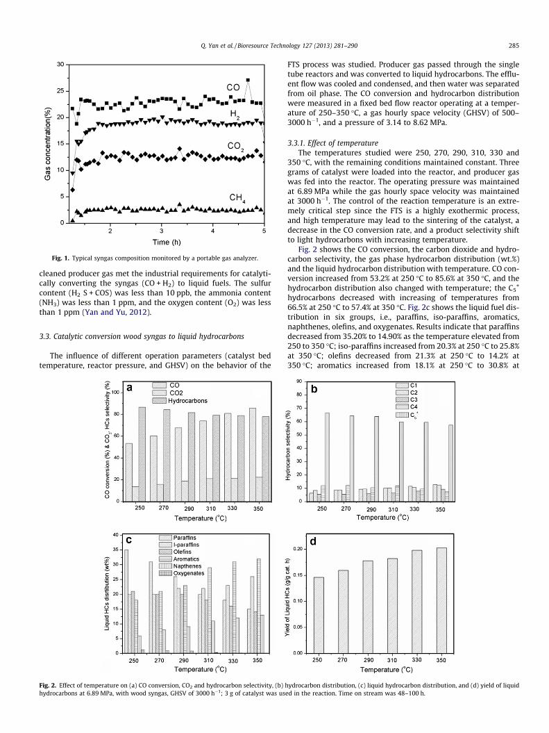
Fig. 1. Typical syngas composition monitored by a portable gas analyzer.
Q. Yan et al. / Bioresource Technology 127 (2013) 281–290 285
cleaned producer gas met the industrial requirements for catalyti-cally converting the syngas (CO + H2) to liquid fuels. The sulfurcontent (H2 S + COS) was less than 10 ppb, the ammonia content(NH3) was less than 1 ppm, and the oxygen content (O2) was lessthan 1 ppm (Yan and Yu, 2012).
3.3. Catalytic conversion wood syngas to liquid hydrocarbons
The influence of different operation parameters (catalyst bedtemperature, reactor pressure, and GHSV) on the behavior of the
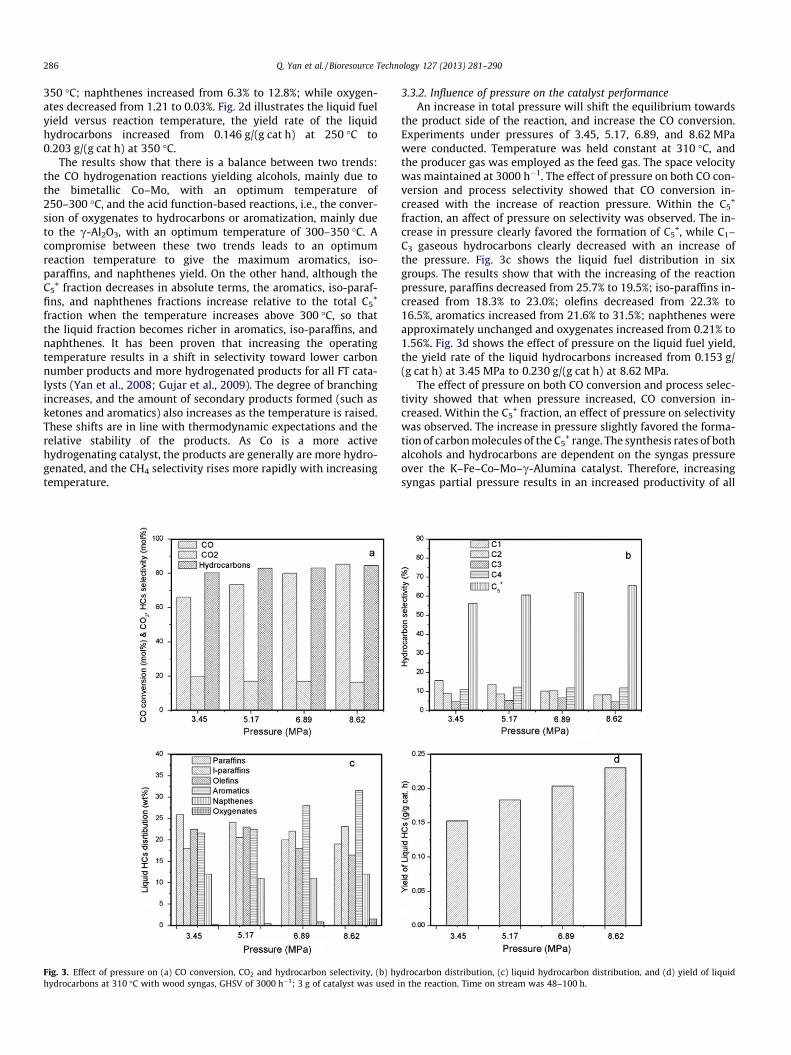
Fig. 2. Effect of temperature on (a) CO conversion, CO2 and hydrocarbon selectivity, (b) hhydrocarbons at 6.89 MPa, with wood syngas, GHSV of 3000 h�1; 3 g of catalyst was us
FTS process was studied. Producer gas passed through the singletube reactors and was converted to liquid hydrocarbons. The efflu-ent flow was cooled and condensed, and then water was separatedfrom oil phase. The CO conversion and hydrocarbon distributionwere measured in a fixed bed flow reactor operating at a temper-ature of 250–350 �C, a gas hourly space velocity (GHSV) of 500–3000 h�1, and a pressure of 3.14 to 8.62 MPa.
3.3.1. Effect of temperatureThe temperatures studied were 250, 270, 290, 310, 330 and
350 �C, with the remaining conditions maintained constant. Threegrams of catalyst were loaded into the reactor, and producer gaswas fed into the reactor. The operating pressure was maintainedat 6.89 MPa while the gas hourly space velocity was maintainedat 3000 h�1. The control of the reaction temperature is an extre-mely critical step since the FTS is a highly exothermic process,and high temperature may lead to the sintering of the catalyst, adecrease in the CO conversion rate, and a product selectivity shiftto light hydrocarbons with increasing temperature.
Fig. 2 shows the CO conversion, the carbon dioxide and hydro-carbon selectivity, the gas phase hydrocarbon distribution (wt.%)and the liquid hydrocarbon distribution with temperature. CO con-version increased from 53.2% at 250 �C to 85.6% at 350 �C, and thehydrocarbon distribution also changed with temperature; the C5
+
hydrocarbons decreased with increasing of temperatures from66.5% at 250 �C to 57.4% at 350 �C. Fig. 2c shows the liquid fuel dis-tribution in six groups, i.e., paraffins, iso-paraffins, aromatics,naphthenes, olefins, and oxygenates. Results indicate that paraffinsdecreased from 35.20% to 14.90% as the temperature elevated from250 to 350 �C; iso-paraffins increased from 20.3% at 250 �C to 25.8%at 350 �C; olefins decreased from 21.3% at 250 �C to 14.2% at350 �C; aromatics increased from 18.1% at 250 �C to 30.8% at
ydrocarbon distribution, (c) liquid hydrocarbon distribution, and (d) yield of liquided in the reaction. Time on stream was 48–100 h.
286 Q. Yan et al. / Bioresource Technology 127 (2013) 281–290
350 �C; naphthenes increased from 6.3% to 12.8%; while oxygen-ates decreased from 1.21 to 0.03%. Fig. 2d illustrates the liquid fuelyield versus reaction temperature, the yield rate of the liquidhydrocarbons increased from 0.146 g/(g cat h) at 250 �C to0.203 g/(g cat h) at 350 �C.
The results show that there is a balance between two trends:the CO hydrogenation reactions yielding alcohols, mainly due tothe bimetallic Co–Mo, with an optimum temperature of250–300 �C, and the acid function-based reactions, i.e., the conver-sion of oxygenates to hydrocarbons or aromatization, mainly dueto the c-Al2O3, with an optimum temperature of 300–350 �C. Acompromise between these two trends leads to an optimumreaction temperature to give the maximum aromatics, iso-paraffins, and naphthenes yield. On the other hand, although theC5
+ fraction decreases in absolute terms, the aromatics, iso-paraf-fins, and naphthenes fractions increase relative to the total C5
+
fraction when the temperature increases above 300 �C, so thatthe liquid fraction becomes richer in aromatics, iso-paraffins, andnaphthenes. It has been proven that increasing the operatingtemperature results in a shift in selectivity toward lower carbonnumber products and more hydrogenated products for all FT cata-lysts (Yan et al., 2008; Gujar et al., 2009). The degree of branchingincreases, and the amount of secondary products formed (such asketones and aromatics) also increases as the temperature is raised.These shifts are in line with thermodynamic expectations and therelative stability of the products. As Co is a more activehydrogenating catalyst, the products are generally are more hydro-genated, and the CH4 selectivity rises more rapidly with increasingtemperature.
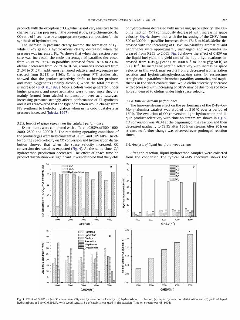
Fig. 3. Effect of pressure on (a) CO conversion, CO2 and hydrocarbon selectivity, (b) hyhydrocarbons at 310 �C with wood syngas, GHSV of 3000 h�1; 3 g of catalyst was used i
3.3.2. Influence of pressure on the catalyst performanceAn increase in total pressure will shift the equilibrium towards
the product side of the reaction, and increase the CO conversion.Experiments under pressures of 3.45, 5.17, 6.89, and 8.62 MPawere conducted. Temperature was held constant at 310 �C, andthe producer gas was employed as the feed gas. The space velocitywas maintained at 3000 h�1. The effect of pressure on both CO con-version and process selectivity showed that CO conversion in-creased with the increase of reaction pressure. Within the C5
+
fraction, an affect of pressure on selectivity was observed. The in-crease in pressure clearly favored the formation of C5
+, while C1–C3 gaseous hydrocarbons clearly decreased with an increase ofthe pressure. Fig. 3c shows the liquid fuel distribution in sixgroups. The results show that with the increasing of the reactionpressure, paraffins decreased from 25.7% to 19.5%; iso-paraffins in-creased from 18.3% to 23.0%; olefins decreased from 22.3% to16.5%, aromatics increased from 21.6% to 31.5%; naphthenes wereapproximately unchanged and oxygenates increased from 0.21% to1.56%. Fig. 3d shows the effect of pressure on the liquid fuel yield,the yield rate of the liquid hydrocarbons increased from 0.153 g/(g cat h) at 3.45 MPa to 0.230 g/(g cat h) at 8.62 MPa.
The effect of pressure on both CO conversion and process selec-tivity showed that when pressure increased, CO conversion in-creased. Within the C5
+ fraction, an effect of pressure on selectivitywas observed. The increase in pressure slightly favored the forma-tion of carbon molecules of the C5
+ range. The synthesis rates of bothalcohols and hydrocarbons are dependent on the syngas pressureover the K–Fe–Co–Mo–c-Alumina catalyst. Therefore, increasingsyngas partial pressure results in an increased productivity of all
drocarbon distribution, (c) liquid hydrocarbon distribution, and (d) yield of liquidn the reaction. Time on stream was 48–100 h.
Q. Yan et al. / Bioresource Technology 127 (2013) 281–290 287
products with the exception of CO2, which is not very sensitive to thechange in syngas pressure. In the present study, a stoichiometric H2/CO ratio of 1 seems to be an appropriate syngas composition for thesynthesis of hydrocarbons.
The increase in pressure clearly favored the formation of C5+,
while C1–C3 gaseous hydrocarbons clearly decreased when thepressure was increased. Fig. 7c shows that when the reaction pres-sure was increased, the mole percentage of paraffins decreasedfrom 25.7% to 19.5%, iso-paraffins increased from 18.3% to 23.0%,olefins decreased from 22.3% to 16.5%, aromatics increased from21.6% to 31.5%, naphthenes remained relative, and oxygenates in-creased from 0.21% to 1.56%. Some previous FTS studies alsoshowed that the product selectivity shifts to heavier productsand more oxygenates (mainly alcohols) when the total pressureis increased (Li et al., 1998). More alcohols were generated underhigher pressure, and more aromatics were formed since they aremainly formed from alcohol condensation over acid catalysts.Increasing pressure strongly affects performance of FT synthesis,and it was discovered that the type of reaction would change fromFTS synthesis to hydroformylation when using cobalt catalysts aspressure increased (Iglesia, 1997).
3.3.3. Impact of space velocity on the catalyst performanceExperiments were completed with different GHSVs of 500, 1000,
2000, 2500 and 3000 h�1. The remaining operating conditions ofthe producer gas were held constant at 310 �C and 6.89 MPa. The ef-fect of the space velocity on CO conversion and hydrocarbon distri-bution showed that when the space velocity increased, COconversion decreased as expected (Fig. 4). At the same time, C5
+
hydrocarbon production decreased. The effect of space time onproduct distribution was significant. It was observed that the yields
Fig. 4. Effect of GHSV on (a) CO conversion, CO2 and hydrocarbon selectivity, (b) hydhydrocarbons at 310 �C, 6.89 MPa with wood syngas; 3 g of catalyst was used in the rea
of hydrocarbons decreased with increasing space velocity. The gas-oline fraction (C5
+) continuously decreased with increasing spacevelocity. Fig. 4c shows that with the increasing of the GHSV from500 to 3000 h�1, paraffins increased from 17.1% to 30.0%.Olefins de-creased with the increasing of GHSV. Iso-paraffins, aromatics, andnaphthenes were approximately unchanged, and oxygenates in-creased from 0.25% to 2.06%. Fig. 3d shows the effect of GHSV onthe liquid fuel yield, the yield rate of the liquid hydrocarbons in-creased from 0.08 g/(g cat h) at 1000 h�1 to 0.276 g/(g cat h) at5000 h�1.The increasing paraffin selectivity with increasing spacevelocity in this work may results from a decreased isomerizationreaction and hydrotreating/hydrocracking rates for restructurestraight chain paraffins to branched paraffins, aromatics, and naph-thenes in the short contact time, while olefin selectivity decreasewith decreased with increasing of GHSV may be due to less of alco-hols condensed to olefins under high space velocity.
3.3.4. Time-on-stream performanceThe time-on-stream effect on the performance of the K–Fe–Co–
Mo–c–alumina catalyst was studied at 310 �C over a period of160 h. The evolution of CO conversion, light hydrocarbon and li-quid product selectivity with time on stream are shown in Fig. 5.CO conversion was 78.3% at the beginning of the reaction and thendecreased gradually to 72.5% after 160 h on stream. After 80 h onstream, no further change was observed over prolonged reactiontimes.
3.4. Analysis of liquid fuel from wood syngas
After the reaction, liquid hydrocarbon samples were collectedfrom the condenser. The typical GC–MS spectrum shows the
rocarbon distribution, (c) liquid hydrocarbon distribution and (d) yield of liquidction. Time on stream was 48–100 h.
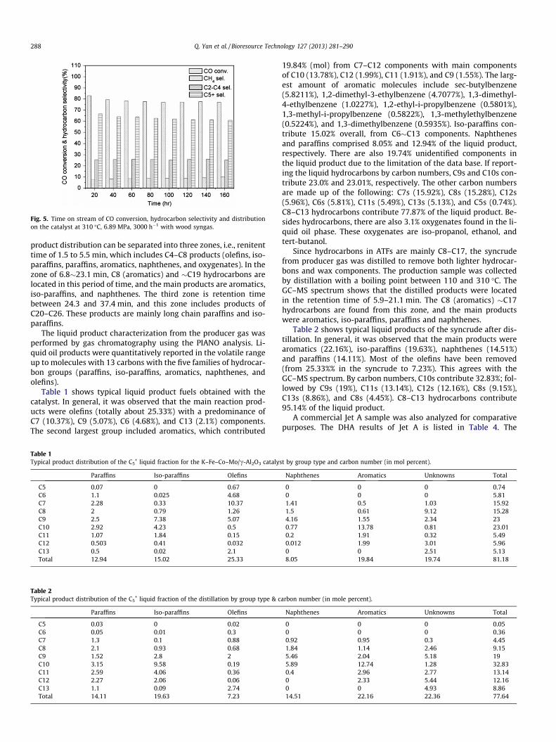
Fig. 5. Time on stream of CO conversion, hydrocarbon selectivity and distributionon the catalyst at 310 �C, 6.89 MPa, 3000 h�1 with wood syngas.
288 Q. Yan et al. / Bioresource Technology 127 (2013) 281–290
product distribution can be separated into three zones, i.e., renitenttime of 1.5 to 5.5 min, which includes C4–C8 products (olefins, iso-paraffins, paraffins, aromatics, naphthenes, and oxygenates). In thezone of 6.8�23.1 min, C8 (aromatics) and �C19 hydrocarbons arelocated in this period of time, and the main products are aromatics,iso-paraffins, and naphthenes. The third zone is retention timebetween 24.3 and 37.4 min, and this zone includes products ofC20–C26. These products are mainly long chain paraffins and iso-paraffins.
The liquid product characterization from the producer gas wasperformed by gas chromatography using the PIANO analysis. Li-quid oil products were quantitatively reported in the volatile rangeup to molecules with 13 carbons with the five families of hydrocar-bon groups (paraffins, iso-paraffins, aromatics, naphthenes, andolefins).
Table 1 shows typical liquid product fuels obtained with thecatalyst. In general, it was observed that the main reaction prod-ucts were olefins (totally about 25.33%) with a predominance ofC7 (10.37%), C9 (5.07%), C6 (4.68%), and C13 (2.1%) components.The second largest group included aromatics, which contributed
Table 1Typical product distribution of the C5
+ liquid fraction for the K–Fe–Co–Mo/c-Al2O3 catalys
Paraffins Iso-paraffins Olefins
C5 0.07 0 0.67C6 1.1 0.025 4.68C7 2.28 0.33 10.37C8 2 0.79 1.26C9 2.5 7.38 5.07C10 2.92 4.23 0.5C11 1.07 1.84 0.15C12 0.503 0.41 0.032C13 0.5 0.02 2.1Total 12.94 15.02 25.33
Table 2Typical product distribution of the C5
+ liquid fraction of the distillation by group type & c
Paraffins Iso-paraffins Olefins
C5 0.03 0 0.02C6 0.05 0.01 0.3C7 1.3 0.1 0.88C8 2.1 0.93 0.68C9 1.52 2.8 2C10 3.15 9.58 0.19C11 2.59 4.06 0.36C12 2.27 2.06 0.06C13 1.1 0.09 2.74Total 14.11 19.63 7.23
19.84% (mol) from C7–C12 components with main componentsof C10 (13.78%), C12 (1.99%), C11 (1.91%), and C9 (1.55%). The larg-est amount of aromatic molecules include sec-butylbenzene(5.8211%), 1,2-dimethyl-3-ethylbenzene (4.7077%), 1,3-dimethyl-4-ethylbenzene (1.0227%), 1,2-ethyl-i-propylbenzene (0.5801%),1,3-methyl-i-propylbenzene (0.5822%), 1,3-methylethylbenzene(0.5224%), and 1,3-dimethylbenzene (0.5935%). Iso-paraffins con-tribute 15.02% overall, from C6�C13 components. Naphthenesand paraffins comprised 8.05% and 12.94% of the liquid product,respectively. There are also 19.74% unidentified components inthe liquid product due to the limitation of the data base. If report-ing the liquid hydrocarbons by carbon numbers, C9s and C10s con-tribute 23.0% and 23.01%, respectively. The other carbon numbersare made up of the following: C7s (15.92%), C8s (15.28%), C12s(5.96%), C6s (5.81%), C11s (5.49%), C13s (5.13%), and C5s (0.74%).C8–C13 hydrocarbons contribute 77.87% of the liquid product. Be-sides hydrocarbons, there are also 3.1% oxygenates found in the li-quid oil phase. These oxygenates are iso-propanol, ethanol, andtert-butanol.
Since hydrocarbons in ATFs are mainly C8–C17, the syncrudefrom producer gas was distilled to remove both lighter hydrocar-bons and wax components. The production sample was collectedby distillation with a boiling point between 110 and 310 �C. TheGC–MS spectrum shows that the distilled products were locatedin the retention time of 5.9–21.1 min. The C8 (aromatics) �C17hydrocarbons are found from this zone, and the main productswere aromatics, iso-paraffins, paraffins and naphthenes.
Table 2 shows typical liquid products of the syncrude after dis-tillation. In general, it was observed that the main products werearomatics (22.16%), iso-paraffins (19.63%), naphthenes (14.51%)and paraffins (14.11%). Most of the olefins have been removed(from 25.33%% in the syncrude to 7.23%). This agrees with theGC–MS spectrum. By carbon numbers, C10s contribute 32.83%; fol-lowed by C9s (19%), C11s (13.14%), C12s (12.16%), C8s (9.15%),C13s (8.86%), and C8s (4.45%). C8–C13 hydrocarbons contribute95.14% of the liquid product.
A commercial Jet A sample was also analyzed for comparativepurposes. The DHA results of Jet A is listed in Table 4. The
t by group type and carbon number (in mol percent).
Naphthenes Aromatics Unknowns Total
0 0 0 0.740 0 0 5.811.41 0.5 1.03 15.921.5 0.61 9.12 15.284.16 1.55 2.34 230.77 13.78 0.81 23.010.2 1.91 0.32 5.490.012 1.99 3.01 5.960 0 2.51 5.138.05 19.84 19.74 81.18
arbon number (in mole percent).
Naphthenes Aromatics Unknowns Total
0 0 0 0.050 0 0 0.360.92 0.95 0.3 4.451.84 1.14 2.46 9.155.46 2.04 5.18 195.89 12.74 1.28 32.830.4 2.96 2.77 13.140 2.33 5.44 12.160 0 4.93 8.8614.51 22.16 22.36 77.64
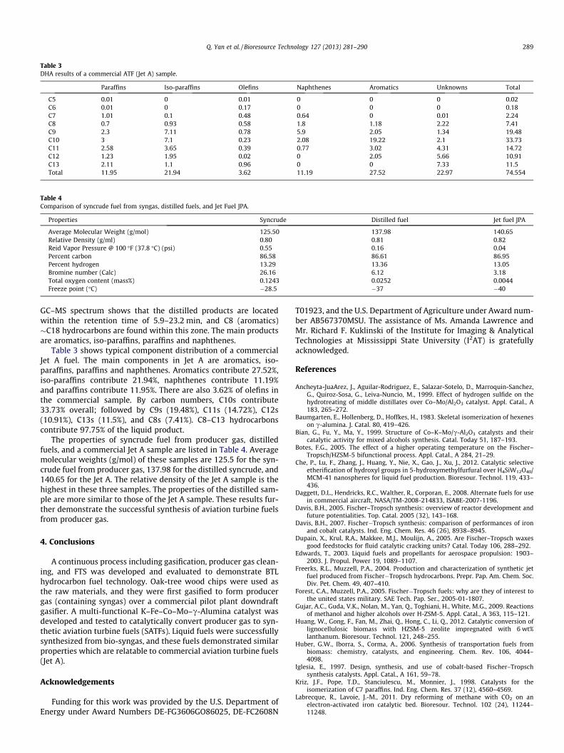
Table 3DHA results of a commercial ATF (Jet A) sample.
Paraffins Iso-paraffins Olefins Naphthenes Aromatics Unknowns Total
C5 0.01 0 0.01 0 0 0 0.02C6 0.01 0 0.17 0 0 0 0.18C7 1.01 0.1 0.48 0.64 0 0.01 2.24C8 0.7 0.93 0.58 1.8 1.18 2.22 7.41C9 2.3 7.11 0.78 5.9 2.05 1.34 19.48C10 3 7.1 0.23 2.08 19.22 2.1 33.73C11 2.58 3.65 0.39 0.77 3.02 4.31 14.72C12 1.23 1.95 0.02 0 2.05 5.66 10.91C13 2.11 1.1 0.96 0 0 7.33 11.5Total 11.95 21.94 3.62 11.19 27.52 22.97 74.554
Table 4Comparison of syncrude fuel from syngas, distilled fuels, and Jet Fuel JPA.
Properties Syncrude Distilled fuel Jet fuel JPA
Average Molecular Weight (g/mol) 125.50 137.98 140.65Relative Density (g/ml) 0.80 0.81 0.82Reid Vapor Pressure @ 100 �F (37.8 �C) (psi) 0.55 0.16 0.04Percent carbon 86.58 86.61 86.95Percent hydrogen 13.29 13.36 13.05Bromine number (Calc) 26.16 6.12 3.18Total oxygen content (mass%) 0.1243 0.0252 0.0044Freeze point (�C) �28.5 �37 �40
Q. Yan et al. / Bioresource Technology 127 (2013) 281–290 289
GC–MS spectrum shows that the distilled products are locatedwithin the retention time of 5.9–23.2 min, and C8 (aromatics)�C18 hydrocarbons are found within this zone. The main productsare aromatics, iso-paraffins, paraffins and naphthenes.
Table 3 shows typical component distribution of a commercialJet A fuel. The main components in Jet A are aromatics, iso-paraffins, paraffins and naphthenes. Aromatics contribute 27.52%,iso-paraffins contribute 21.94%, naphthenes contribute 11.19%and paraffins contribute 11.95%. There are also 3.62% of olefins inthe commercial sample. By carbon numbers, C10s contribute33.73% overall; followed by C9s (19.48%), C11s (14.72%), C12s(10.91%), C13s (11.5%), and C8s (7.41%). C8–C13 hydrocarbonscontribute 97.75% of the liquid product.
The properties of syncrude fuel from producer gas, distilledfuels, and a commercial Jet A sample are listed in Table 4. Averagemolecular weights (g/mol) of these samples are 125.5 for the syn-crude fuel from producer gas, 137.98 for the distilled syncrude, and140.65 for the Jet A. The relative density of the Jet A sample is thehighest in these three samples. The properties of the distilled sam-ple are more similar to those of the Jet A sample. These results fur-ther demonstrate the successful synthesis of aviation turbine fuelsfrom producer gas.
4. Conclusions
A continuous process including gasification, producer gas clean-ing, and FTS was developed and evaluated to demonstrate BTLhydrocarbon fuel technology. Oak-tree wood chips were used asthe raw materials, and they were first gasified to form producergas (containing syngas) over a commercial pilot plant downdraftgasifier. A multi-functional K–Fe–Co–Mo–c-Alumina catalyst wasdeveloped and tested to catalytically convert producer gas to syn-thetic aviation turbine fuels (SATFs). Liquid fuels were successfullysynthesized from bio-syngas, and these fuels demonstrated similarproperties which are relatable to commercial aviation turbine fuels(Jet A).
Acknowledgements
Funding for this work was provided by the U.S. Department ofEnergy under Award Numbers DE-FG3606GO86025, DE-FC2608N
T01923, and the U.S. Department of Agriculture under Award num-ber AB567370MSU. The assistance of Ms. Amanda Lawrence andMr. Richard F. Kuklinski of the Institute for Imaging & AnalyticalTechnologies at Mississippi State University (I2AT) is gratefullyacknowledged.
References
Ancheyta-JuaArez, J., Aguilar-Rodriguez, E., Salazar-Sotelo, D., Marroquin-Sanchez,G., Quiroz-Sosa, G., Leiva-Nuncio, M., 1999. Effect of hydrogen sulfide on thehydrotreating of middle distillates over Co–Mo/Al2O3 catalyst. Appl. Catal., A183, 265–272.
Baumgarten, E., Hollenberg, D., Hoffkes, H., 1983. Skeletal isomerization of hexeneson c-alumina. J. Catal. 80, 419–426.
Bian, G., Fu, Y., Ma, Y., 1999. Structure of Co–K–Mo/c-Al2O3 catalysts and theircatalytic activity for mixed alcohols synthesis. Catal. Today 51, 187–193.
Botes, F.G., 2005. The effect of a higher operating temperature on the Fischer–Tropsch/HZSM-5 bifunctional process. Appl. Catal., A 284, 21–29.
Che, P., Lu, F., Zhang, J., Huang, Y., Nie, X., Gao, J., Xu, J., 2012. Catalytic selectiveetherification of hydroxyl groups in 5-hydroxymethylfurfural over H4SiW12O40/MCM-41 nanospheres for liquid fuel production. Bioresour. Technol. 119, 433–436.
Daggett, D.L., Hendricks, R.C., Walther, R., Corporan, E., 2008. Alternate fuels for usein commercial aircraft, NASA/TM-2008-214833, ISABE-2007-1196.
Davis, B.H., 2005. Fischer–Tropsch synthesis: overview of reactor development andfuture potentialities. Top. Catal. 2005 (32), 143–168.
Davis, B.H., 2007. Fischer�Tropsch synthesis: comparison of performances of ironand cobalt catalysts. Ind. Eng. Chem. Res. 46 (26), 8938–8945.
Dupain, X., Krul, R.A., Makkee, M.J., Moulijn, A., 2005. Are Fischer–Tropsch waxesgood feedstocks for fluid catalytic cracking units? Catal. Today 106, 288–292.
Edwards, T., 2003. Liquid fuels and propellants for aerospace propulsion: 1903–2003. J. Propul. Power 19, 1089–1107.
Freerks, R.L., Muzzell, P.A., 2004. Production and characterization of synthetic jetfuel produced from Fischer�Tropsch hydrocarbons. Prepr. Pap. Am. Chem. Soc.Div. Pet. Chem. 49, 407–410.
Forest, C.A., Muzzell, P.A., 2005. Fischer�Tropsch fuels: why are they of interest tothe united states military. SAE Tech. Pap. Ser., 2005-01-1807.
Gujar, A.C., Guda, V.K., Nolan, M., Yan, Q., Toghiani, H., White, M.G., 2009. Reactionsof methanol and higher alcohols over H-ZSM-5. Appl. Catal., A 363, 115–121.
Huang, W., Gong, F., Fan, M., Zhai, Q., Hong, C., Li, Q., 2012. Catalytic conversion oflignocellulosic biomass with HZSM-5 zeolite impregnated with 6 wt%lanthanum. Bioresour. Technol. 121, 248–255.
Huber, G.W., Iborra, S., Corma, A., 2006. Synthesis of transportation fuels frombiomass: chemistry, catalysts, and engineering. Chem. Rev. 106, 4044–4098.
Iglesia, E., 1997. Design, synthesis, and use of cobalt-based Fischer–Tropschsynthesis catalysts. Appl. Catal., A 161, 59–78.
Kriz, J.F., Pope, T.D., Stanciulescu, M., Monnier, J., 1998. Catalysts for theisomerization of C7 paraffins. Ind. Eng. Chem. Res. 37 (12), 4560–4569.
Labrecque, R., Lavoie, J.-M., 2011. Dry reforming of methane with CO2 on anelectron-activated iron catalytic bed. Bioresour. Technol. 102 (24), 11244–11248.

290 Q. Yan et al. / Bioresource Technology 127 (2013) 281–290
Lamprecht, D., 2007. Hydrogenation of Fischer�Tropsch synthetic crude. EnergyFuels 21 (5), 2509–2513.
Leckel, D., 2009a. Diesel production from Fischer�Tropsch: the past, the present,and new concepts. Energy Fuels 23 (5), 2342–2358.
Leckel, D., 2009b. Hydroprocessing Euro 4-type diesel from high-temperatureFischer�Tropsch vacuum gas oils. Energy Fuels 23 (1), 38–45.
Li, Z., Fu, Y., Bao, J., Jiang, M., Hu, T., Liu, Tao., Xie, Ya, 2001. Effect of cobalt promoteron Co–Mo–K/C catalysts used for mixed alcohol synthesis. Appl. Catal., A 220,21–30.
Li, X., Feng, L., Zhenyu, L., Zhong, B., Dadyburjor, D.B., Kugler, E.L., 1998. Higheralcohols from synthesis gas using carbon-supported doped molybdenum-basedcatalysts. Ind. Eng. Chem. Res. 37, 3853–3863.
Moses, C.A., Stavinoha, L.L., Roets, P., 1997. Qualification of Sasol Semi-Synthetic JetA-1 as Commercial Jet Fuel: 1997. SwRI-8531, San Antonio, TX, Nov., 1997.
Nel, R.J.J., de Klerk, A., 2007. Fischer�Tropsch aqueous phase refining by catalyticalcohol dehydration. Ind. Eng. Chem. Res. 46 (11), 3558–3565.
Reddy, K.M., Wei, B., Song, C., 1998. High-temperature simulated distillation GCanalysis of petroleum resids and their products from catalytic upgrading overCo–Mo/Al2O3 catalyst. Catal. Today 43, 187–202.
Sotelo-Boyas, R., Liu, Y., Minowa, T., 2011. Renewable diesel production from thehydrotreating of rapeseed oil with Pt/Zeolite and NiMo/Al2O3 catalysts. Ind. Eng.Chem. Res. 50 (5), 2791–2799.
Wright, M.E., Harvey, B.G., Quintana, R.L., 2008. Highly efficient zirconium-catalyzed batch conversion of 1-butene: a new route to jet fuels. Energy Fuels22 (5), 3299–3302.
Yan Q., Yu, F., 2012. Process development and demonstration of biomass to liquid(BTL) fuels via gasification and catalytic conversion, 2012. Spring Meeting & 8thGlobal Congress on Process Safety. San Diego, CA. March 25–29, 2012. 143c.
Yan, Q., Doan, P.T., Toghiani, H., Gujar, A.C., White, M.G., 2008. Synthesis gas tohydrocarbons over CuO–CoO–Cr2O3/H+-ZSM-5 bifunctional catalysts. J. Phys.Chem. C 112 (31), 11847–11858.