case study: jrc, underwater ship noise characterization ... · pdf filebrüel &...
TRANSCRIPT
01BRÜEL & KJÆR CASE STUDY – UNDERWATER SHIP NOISE CHARACTERIZATION WITH SOUND INTENSITY
UNDERWATER SHIP NOISE CHARACTERIZATION WITH SOUND INTENSITY
CASE STUDY
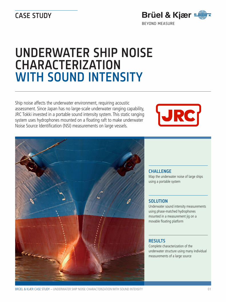
Ship noise affects the underwater environment, requiring acoustic assessment. Since Japan has no large-scale underwater ranging capability, JRC Tokki invested in a portable sound intensity system. This static ranging system uses hydrophones mounted on a floating raft to make underwater Noise Source Identification (NSI) measurements on large vessels.
CHALLENGEMap the underwater noise of large ships using a portable system
RESULTSComplete characterization of the underwater structure using many individual measurements of a large source
SOLUTION Underwater sound intensity measurements using phase-matched hydrophones mounted in a measurement jig on a movable floating platform
BRÜEL & KJÆR CASE STUDY – UNDERWATER SHIP NOISE CHARACTERIZATION WITH SOUND INTENSITY
BACKGROUNDUnderwater noise analysis from ships has traditionally been the exclusive specialty of naval engineers. Nowadays however, commer-cial vessel builders are taking an increasing interest in being just as quiet, with initiatives such as the Green Ship of the Future seeking to encourage fewer noise emissions into the ocean, and less impact on the environment. And in practical terms, for vessels such as fish-eries research ships, understanding their noise signature can be an important consideration in relation to their work.
JRC Tokki Co., Ltd. specialises in system-sup-port engineering for installations on ships, and the manufacture of peripheral equipment. The company also provides repair and overhaul services of defence electronics for ships and aircraft. For JRC Tokki, it is important to be able to measure the underwater noise radiat-ed from ships at sea.
02
THE CUSTOMER’S CHALLENGEJapan has no large-scale acoustic underwater ranging system, so in order to get a complete characterisation for the whole of the underwa-ter structure of a ship, a portable system was needed that would enable field measurements to be made. As the curvature of ship’s stern and bow often varies, JRC Tokki required a solution that can account for this by following the hull closely, at a uniform distance.
After deciding on sound intensity, JRC Tokki needed to integrate Brüel & Kjær hydrophones into their sophisticated underwater meas-urement system. Underwater sound intensity measurements are problematic due to the difficulty of determining particle velocity. In order to do this, JRC Tokki needed carefully selected, phase-matched hydrophones in combination with specified cable lengths and special connectors.
“IN ORDER TO ACHIEVE ACCURATE MEASUREMENTS IT IS IMPORTANT NOT ONLY TO USE COHERENT HYDROPHONE PAIRS WITH GOOD PHASE MATCHING, BUT ALSO TO CHOOSE A PROVEN AND RELIABLE PRODUCT WITH GOOD LONG TERM STABILITY AND LOW AGING AND DETERIORATION.”JRC Tokki spokesman
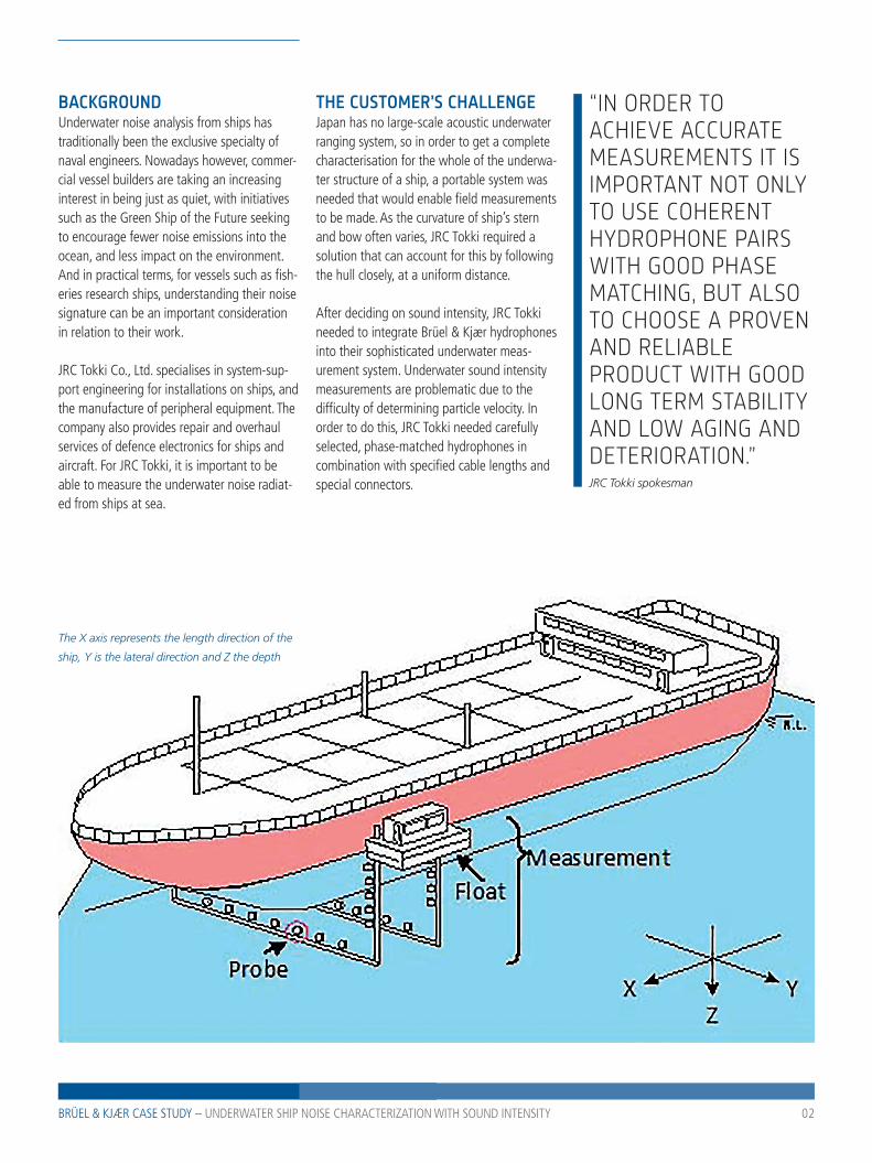
The X axis represents the length direction of the
ship, Y is the lateral direction and Z the depth
03BRÜEL & KJÆR CASE STUDY – UNDERWATER SHIP NOISE CHARACTERIZATION WITH SOUND INTENSITY
THE SOLUTIONJRC Tokki created a portable system to position the measurement transducers at the correct point, which doesn’t require a perma-nent setup.
A floating raft is moved along the sides of the ship, and stops at a planned point where a measurement is made. After a measurement has been done, the floating raft is moved on to the next measurement point. Taken together, all of the points that are measured create a virtual ‘mesh’ that covers the entire underwater surface of the vessel.
The process is repeated for both sides of the vessel, as well as the bottom, in the same way.
Transducer setup JRC Tokki uses a combination of hydrophones mounted side-by-side and face-to-face.
One of the hydrophones is placed opposite the other three, at a distance equidistant from the acoustical centre between them. The mounting positions of the hydrophones and mesh spacing are determined in advance.
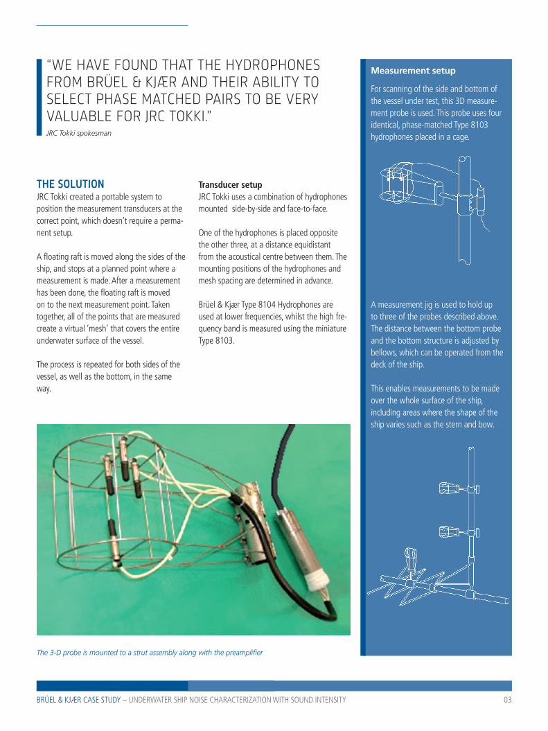
Brüel & Kjær Type 8104 Hydrophones are used at lower frequencies, whilst the high fre-quency band is measured using the miniature Type 8103.
The 3-D probe is mounted to a strut assembly along with the preamplifier
Measurement setup
For scanning of the side and bottom of the vessel under test, this 3D measure-ment probe is used. This probe uses four identical, phase-matched Type 8103 hydrophones placed in a cage.
A measurement jig is used to hold up to three of the probes described above. The distance between the bottom probe and the bottom structure is adjusted by bellows, which can be operated from the deck of the ship.
This enables measurements to be made over the whole surface of the ship, including areas where the shape of the ship varies such as the stern and bow.
“WE HAVE FOUND THAT THE HYDRO PHONES FROM BRÜEL & KJÆR AND THEIR ABILITY TO SELECT PHASE MATCHED PAIRS TO BE VERY VALUABLE FOR JRC TOKKI.”JRC Tokki spokesman
04BRÜEL & KJÆR CASE STUDY – UNDERWATER SHIP NOISE CHARACTERIZATION WITH SOUND INTENSITY
WHY SOUND INTENSITY?Sound intensity is often used for in situ measurements of radiated sound power and of the noise field around an object, since the influence of background noise is cancelled. Using sound intensity makes it possible to make partial measurements of a complex, large sound source.
The distribution of the sound field can be determined by creating both contour and vector plots, by measuring the sound intensity components in the XYZ direction at a number of measurement points on the virtual ‘mesh’ surface of the ship under test.
UNDERWATER SOUND INTENSITY A two-hydrophone technique has been devel-oped where two hydrophones are placed at a well-defined, small distance.
This method uses two phase-matched pressure transducers to measure the sound pressure at two adjacent points with a pre-cisely known spacing. This enables engineers to estimate the particle velocity.
In order to achieve good measurement accu-racy, the hydrophones used must have close matching of both sensitivity and phase re-sponse, and at the same time be well matched to the acoustic characteristics of water.
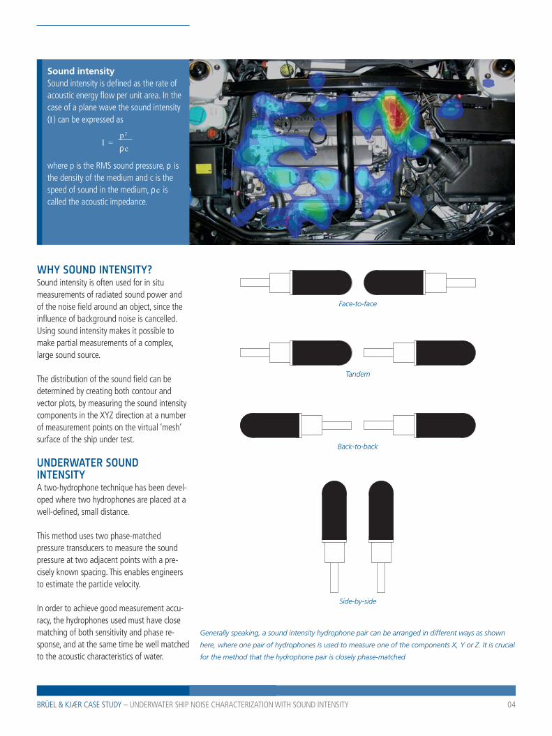
Sound intensitySound intensity is defined as the rate of acoustic energy flow per unit area. In the case of a plane wave the sound intensity (I ) can be expressed as
I = p 2
ρc
where p is the RMS sound pressure, ρ is the density of the medium and c is the speed of sound in the medium, ρc is called the acoustic impedance.
Face-to-face
Tandem
Back-to-back
Side-by-side
Generally speaking, a sound intensity hydrophone pair can be arranged in different ways as shown
here, where one pair of hydrophones is used to measure one of the components X, Y or Z. It is crucial
for the method that the hydrophone pair is closely phase-matched
05BRÜEL & KJÆR CASE STUDY – UNDERWATER SHIP NOISE CHARACTERIZATION WITH SOUND INTENSITY
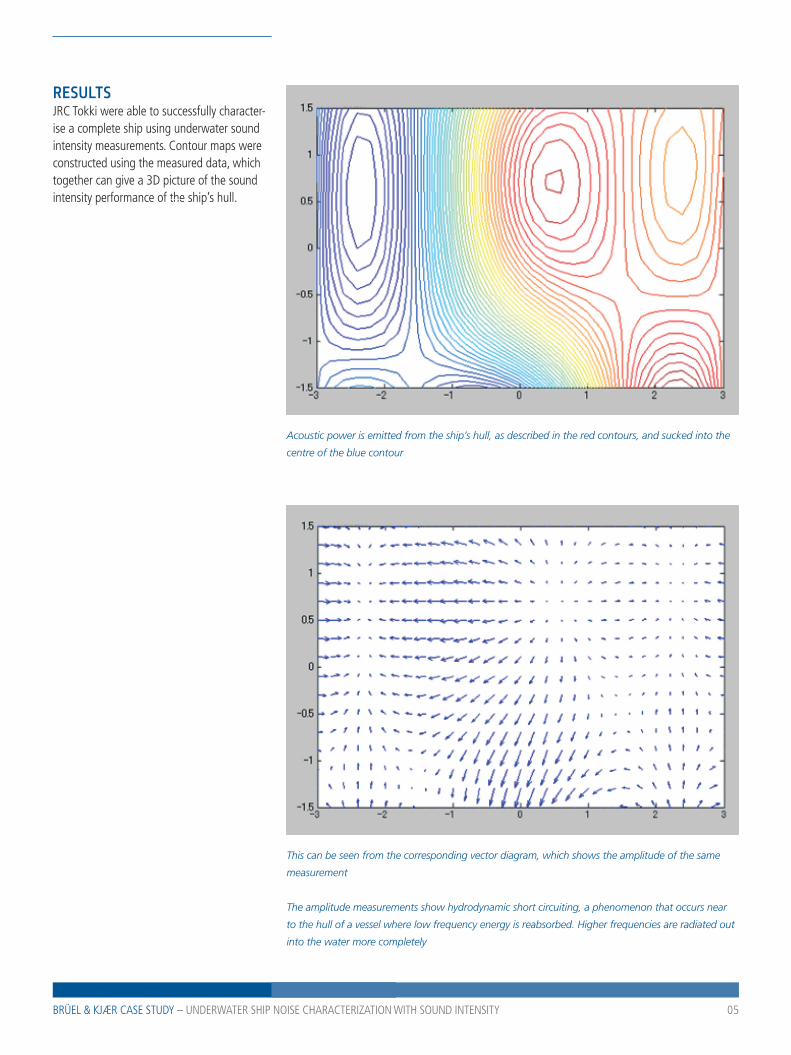
RESULTSJRC Tokki were able to successfully character-ise a complete ship using underwater sound intensity measurements. Contour maps were constructed using the measured data, which together can give a 3D picture of the sound intensity performance of the ship’s hull.
Acoustic power is emitted from the ship’s hull, as described in the red contours, and sucked into the
centre of the blue contour
This can be seen from the corresponding vector diagram, which shows the amplitude of the same
measurement
The amplitude measurements show hydrodynamic short circuiting, a phenomenon that occurs near
to the hull of a vessel where low frequency energy is reabsorbed. Higher frequencies are radiated out
into the water more completely
Copyright © Brüel & Kjær. All rights reserved.
Brüel & Kjær Sound & Vibration Measurement A/S DK-2850 Nærum · DenmarkTelephone: +45 77 41 20 00 · Fax: +45 45 80 14 05 · www.bksv.com · [email protected]
Local representatives and service organisations worldwide
www.bksv.com/casestudies BN 1
352
– 13
2013
-11
CONCLUSIONSound intensity has proven to be a valuable method for measurement of sound emitted to the sea from the hull of a vessel, since the sound intensity method is less susceptible to both external and background noise in the sea than other methods. Sound pressure mapping, for example, would factor in the background noise as well.
JRC Tokki has successfully used sound intensity mapping to obtain detailed on-site information about the contribution to the total radiated noise from the different parts of a complex construction such as a ship.
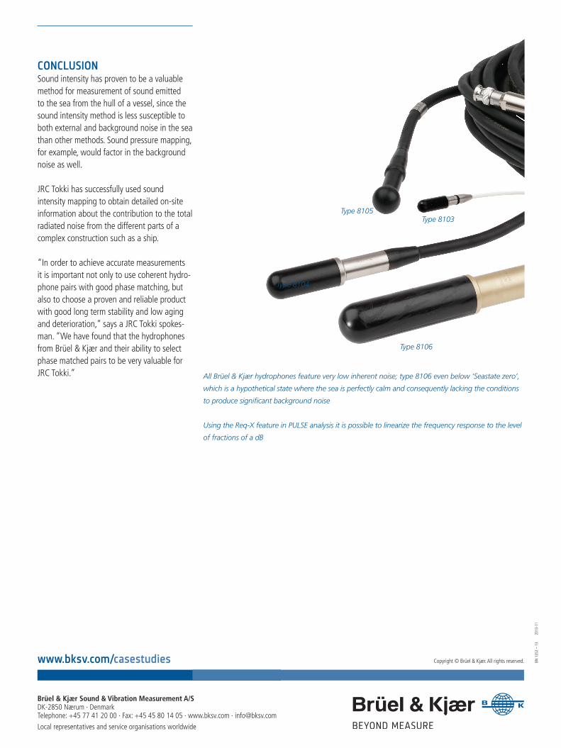
“In order to achieve accurate measurements it is important not only to use coherent hydro-phone pairs with good phase matching, but also to choose a proven and reliable product with good long term stability and low aging and deterioration,” says a JRC Tokki spokes-man. “We have found that the hydrophones from Brüel & Kjær and their ability to select phase matched pairs to be very valuable for JRC Tokki.” All Brüel & Kjær hydrophones feature very low inherent noise; type 8106 even below ‘Seastate zero’,
which is a hypothetical state where the sea is perfectly calm and consequently lacking the conditions
to produce significant background noise
Using the Req-X feature in PULSE analysis it is possible to linearize the frequency response to the level
of fractions of a dB
Type 8105Type 8103
Type 8104
Type 8106