case study – application of sensors in measuring torque and thrust produced by propellers in small...
TRANSCRIPT
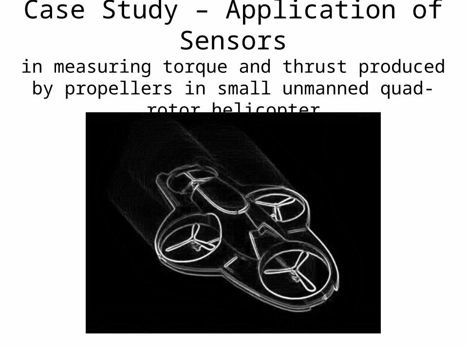
Case Study – Application of Sensorsin measuring torque and thrust produced by propellers
in small unmanned quad-rotor helicopter
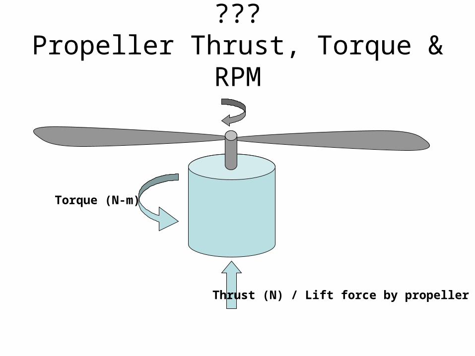
???Propeller Thrust, Torque & RPM
Thrust (N) / Lift force by propeller
Torque (N-m)

)(xfF
x
k
F
kxF
F
Force Applied
Spring Const.
Spring Elongation

How to get this force in terms of electrical Signal / voltage ???
)(ForcefVoltage
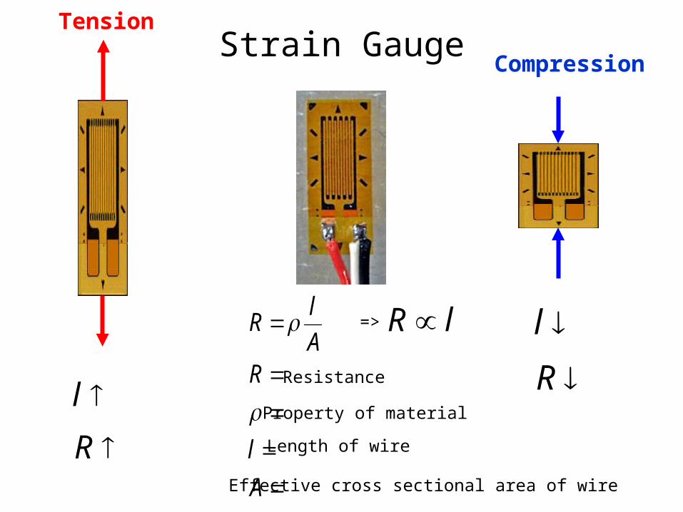
Strain Gauge
Resistance
A
l
RA
lR
Property of material
Length of wire
Effective cross sectional area of wire
lR
R
l
R
l
=>
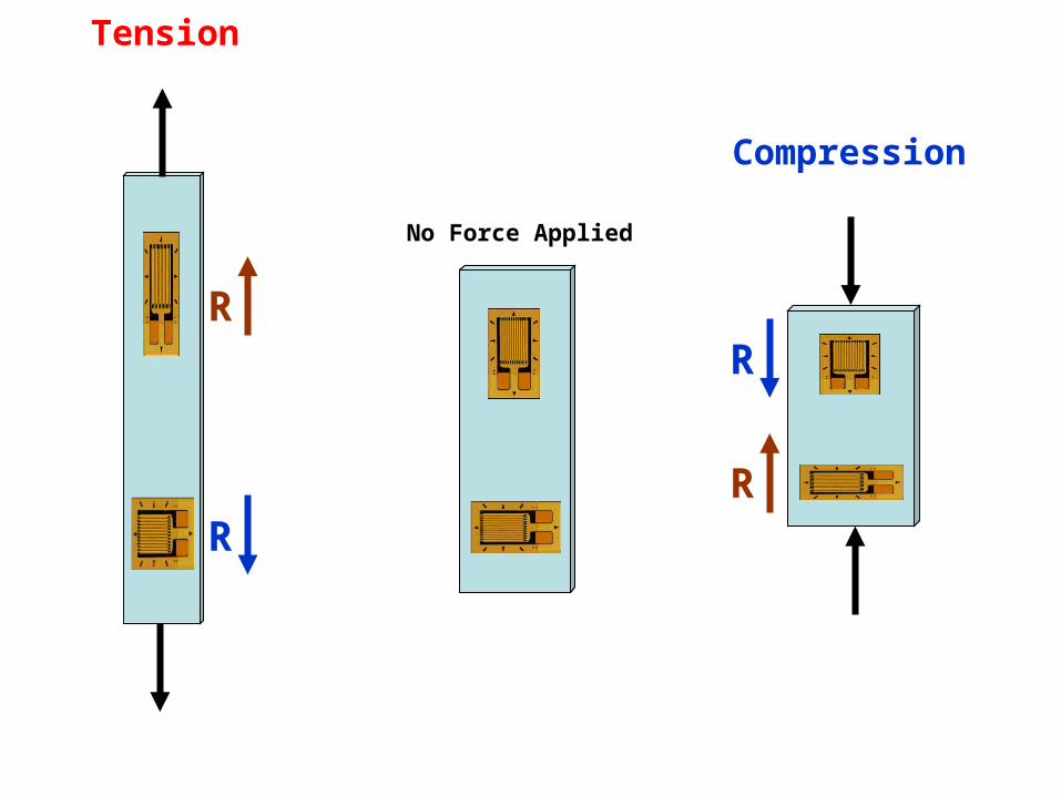
Tension
Compression
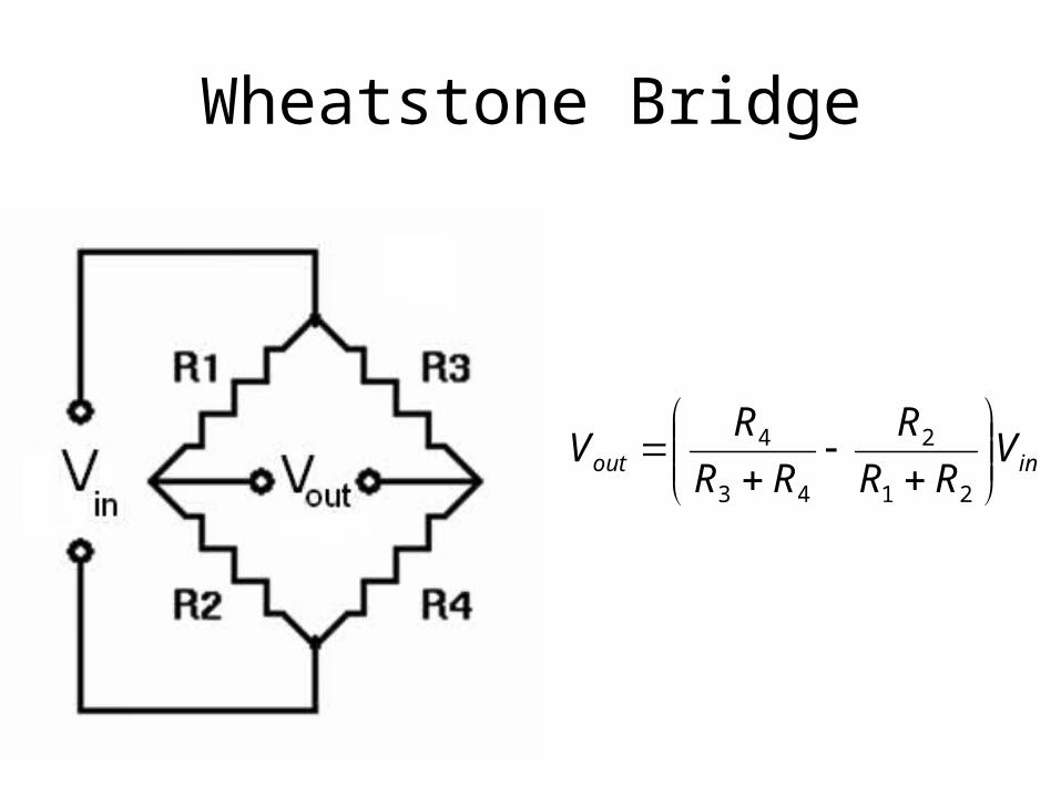
Wheatstone Bridge
inout VRR
R
RR
RV
21
2
43
4

Wheatstone Bridge
(3) (3)
(3) (3) 0
0.533
3
33
3
00.5
,
21
2
43
4
out
out
inout
in
V
V
VRR
R
RR
RV
voltsV
say
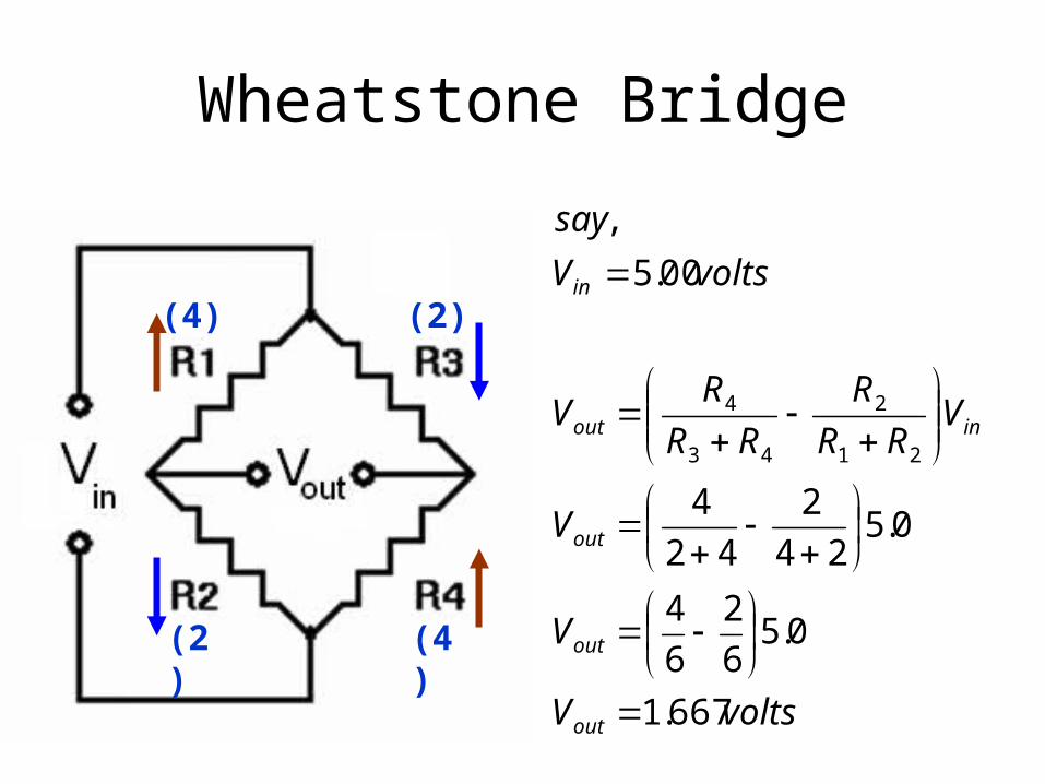
Wheatstone Bridge
(2) (4)
(4) (2)
voltsV
V
V
VRR
R
RR
RV
voltsV
say
out
out
out
inout
in
667.1
0.56
2
6
4
0.524
2
42
4
00.5
,
21
2
43
4
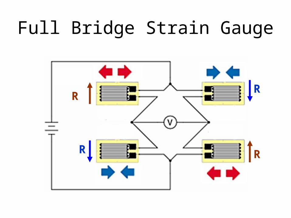
Full Bridge Strain Gauge
RR
R R
Tension
Compression
No Force Applied
R
R
R
R

Bending Beam Load Cell
Strain Gauge
Strain Gauge

Bending Beam Load Cell
Strain GaugeIn Tension
Strain Gaugein compression
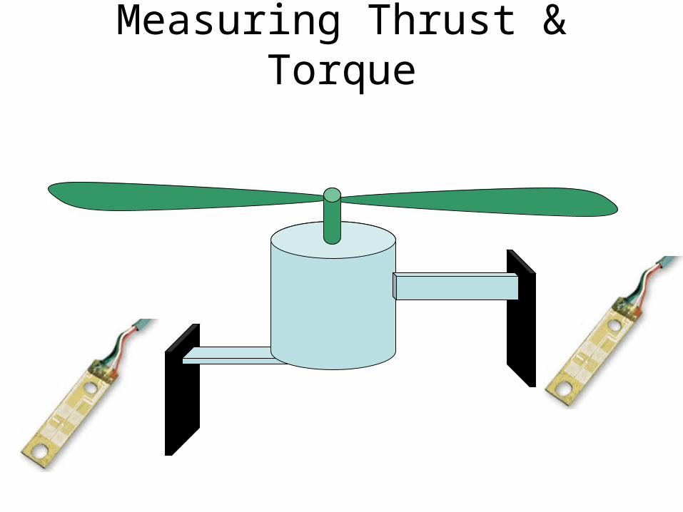
Measuring Thrust & Torque
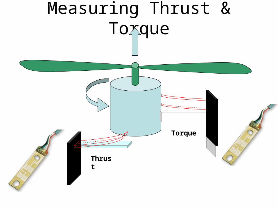
Measuring Thrust & Torque
Thrust
Torque
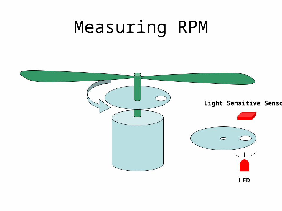
Measuring RPM
Light Sensitive Sensor
LED

Calibration of Sensors


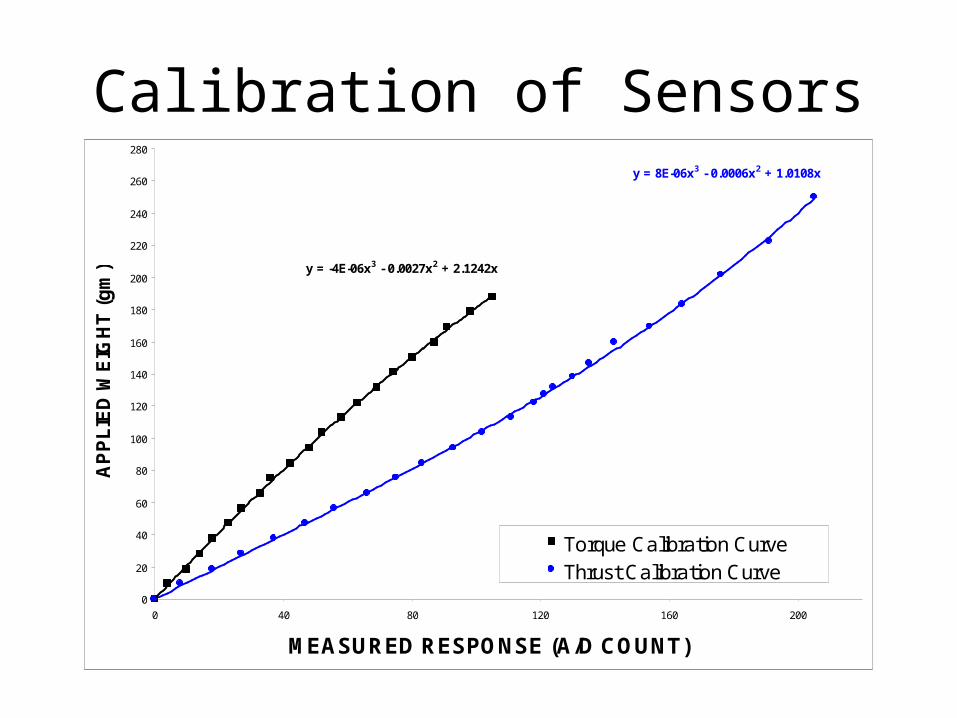
Calibration of Sensorsy = 8E-06x3 - 0.0006x2 + 1.0108x
y = -4E-06x3 - 0.0027x2 + 2.1242x
0
20
40
60
80
100
120
140
160
180
200
220
240
260
280
0 40 80 120 160 200
MEASURED RESPONSE (A/D COUNT)
AP
PL
IED
WE
IGH
T (
gm
)
Torque Calibration CurveThrust Calibration Curve

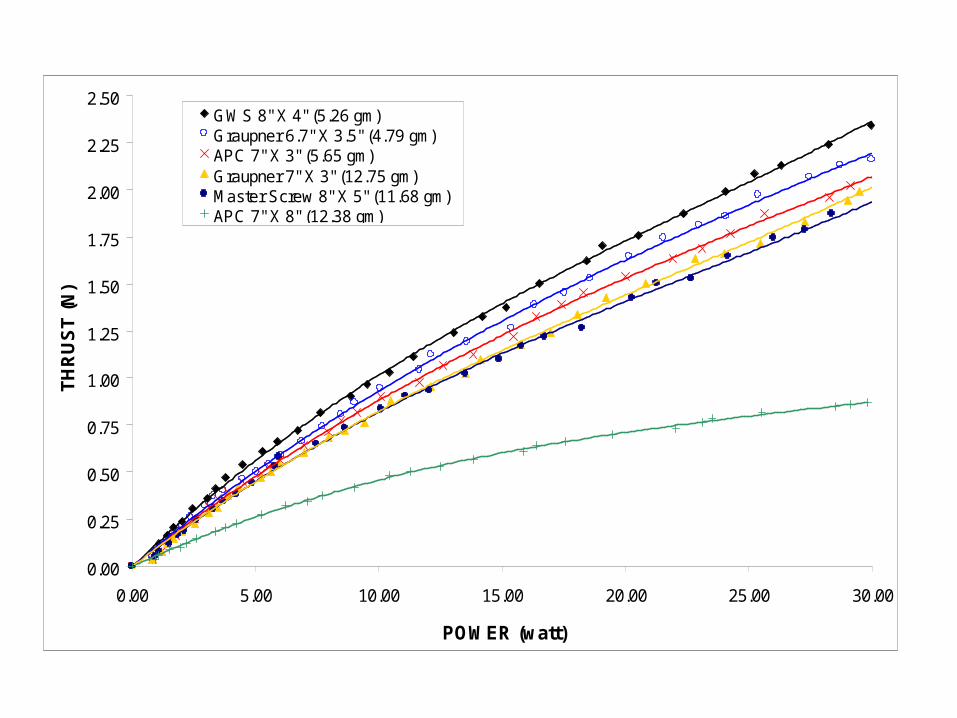
Propeller Characteristics

0
0.1
0.2
0.3
0.4
0.5
0.6
0.7
0.8
0.9
1
0 500 1000 1500 2000 2500 3000 3500 4000 4500
RPM
TH
RU
ST
(N)
APC 7 X 8 Theoretical Result
APC 7 X 8 Dynamometer Test Result

APC 7" X 8" Slo-FLyer Prop
y = -5E-14x3 + 2E-09x2 - 6E-07x
0.0000
0.0025
0.0050
0.0075
0.0100
0.0125
0.0150
0.0175
0.0200
0.0225
0.0250
0 500 1000 1500 2000 2500 3000 3500 4000 4500
RPM
Torq
ue (N
-m)
0.00
0.25
0.50
0.75
1.00
1.25
1.50
1.75
2.00
2.25
2.50
0.00 5.00 10.00 15.00 20.00 25.00 30.00
POWER (watt)
TH
RU
ST
(N
)
GWS 8" X 4" (5.26 gm)Graupner 6.7" X 3.5" (4.79 gm)APC 7" X 3" (5.65 gm)Graupner 7" X 3" (12.75 gm)Master Screw 8" X 5" (11.68 gm)APC 7" X 8" (12.38 gm)

0.0000
0.0050
0.0100
0.0150
0.0200
0.00 5.00 10.00 15.00 20.00 25.00 30.00
POWER (watt)
TOR
QU
E (N
-m)
APC 7" X 8" (12.38 gm)Master Screw 8" X 5" (11.68 gm)GWS 8" X 4" (5.26 gm)Graupner 6.7" X 3.5" (4.79 gm)Graupner 7" X 3" (12.75 gm)APC 7" X 3" (5.65 gm)

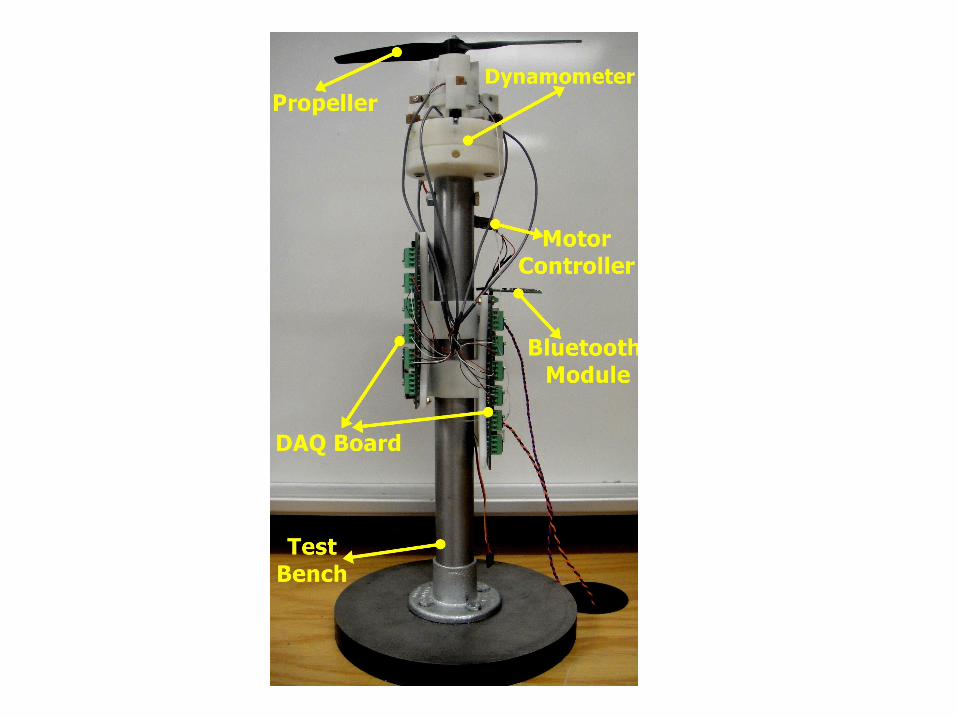
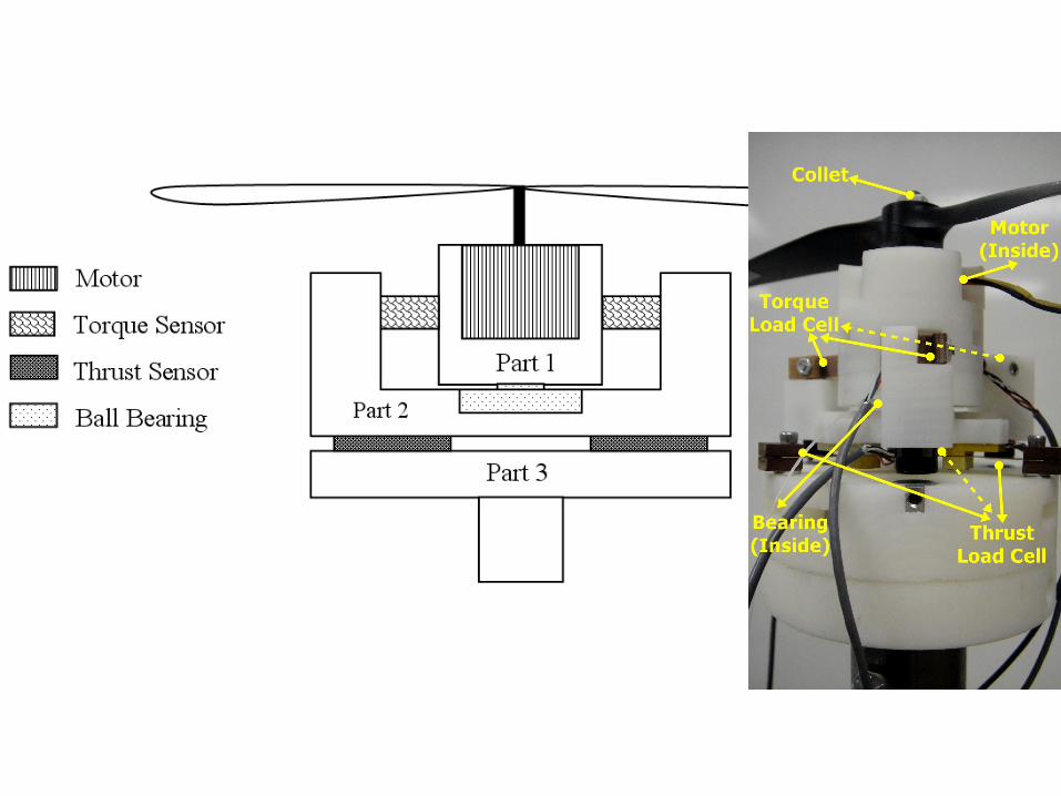
Propeller DynamometerDemo