cascading asynchronous counters - svbit · svbitec.wordpress.com 3 cascading asynchronous counters...
TRANSCRIPT
svbitec.wordpress.com 1
Cascading Asynchronous Counters
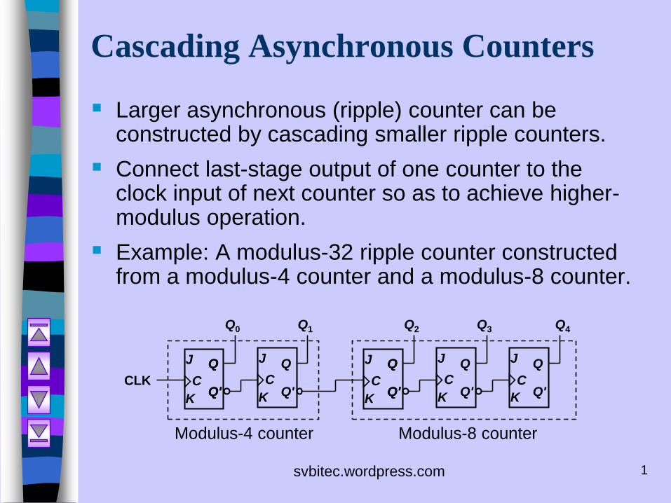
Larger asynchronous (ripple) counter can be constructed by cascading smaller ripple counters.
Connect last-stage output of one counter to the clock input of next counter so as to achieve higher-modulus operation.
Example: A modulus-32 ripple counter constructed from a modulus-4 counter and a modulus-8 counter.
K
J
K
J
Q1Q0
CCCLK
Q
Q'
Q
Q'
Q
Q'K
J
K
J
Q3Q2
CC
K
J
C
Q4
Q
Q'
Q
Q'
Q
Q'
Q
Q'
Modulus-4 counter Modulus-8 counter
svbitec.wordpress.com 2
Cascading Asynchronous Counters
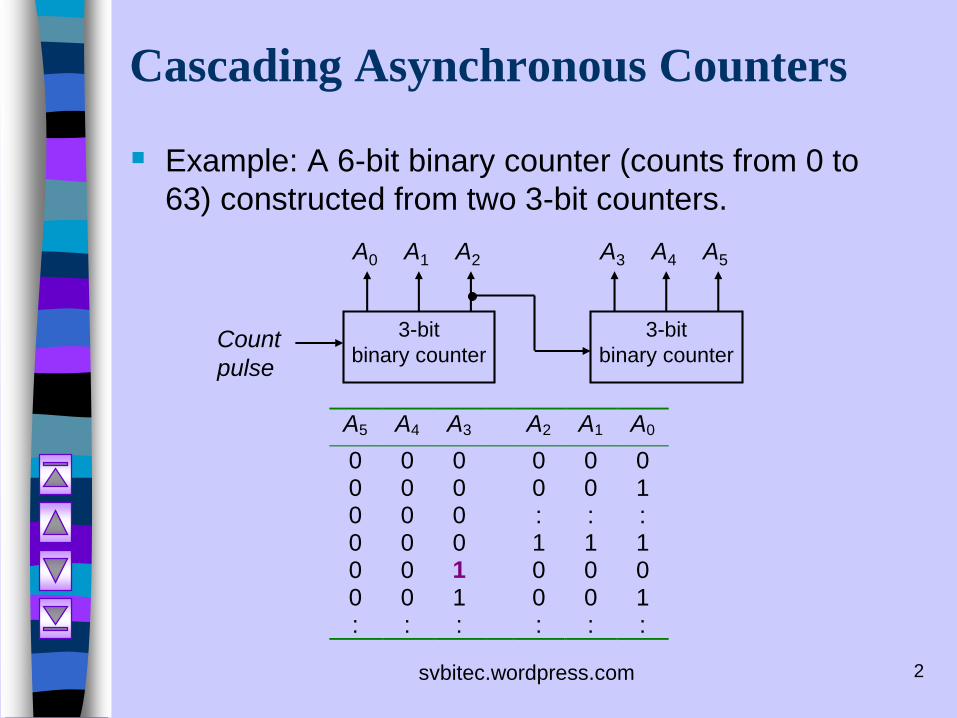
Example: A 6-bit binary counter (counts from 0 to
63) constructed from two 3-bit counters.
3-bit
binary counter
3-bit
binary counterCount
pulse
A0 A1 A2 A3 A4 A5
A5 A4 A3 A2 A1 A0
0 0 0 0 0 00 0 0 0 0 10 0 0 : : :0 0 0 1 1 10 0 1 0 0 00 0 1 0 0 1: : : : : :
svbitec.wordpress.com 3
Cascading Asynchronous Counters
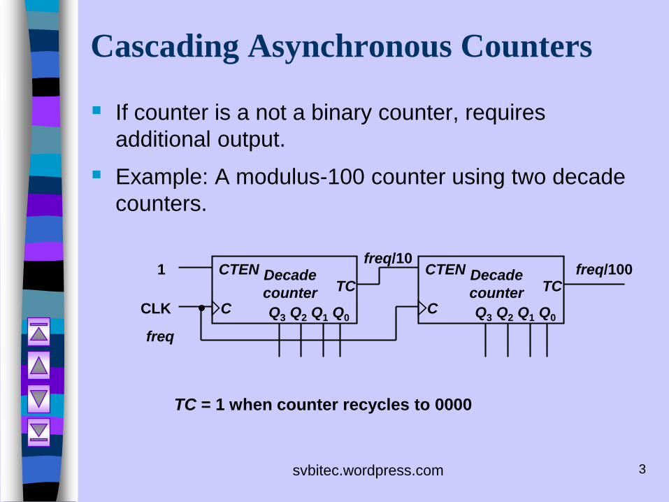
If counter is a not a binary counter, requires
additional output.
Example: A modulus-100 counter using two decade
counters.
CLK
Decade
counter
Q3 Q2 Q1 Q0C
CTENTC
1 Decade
counter
Q3 Q2 Q1 Q0C
CTENTC
freq
freq/10freq/100
TC = 1 when counter recycles to 0000
svbitec.wordpress.com 4
Synchronous (Parallel) Counters
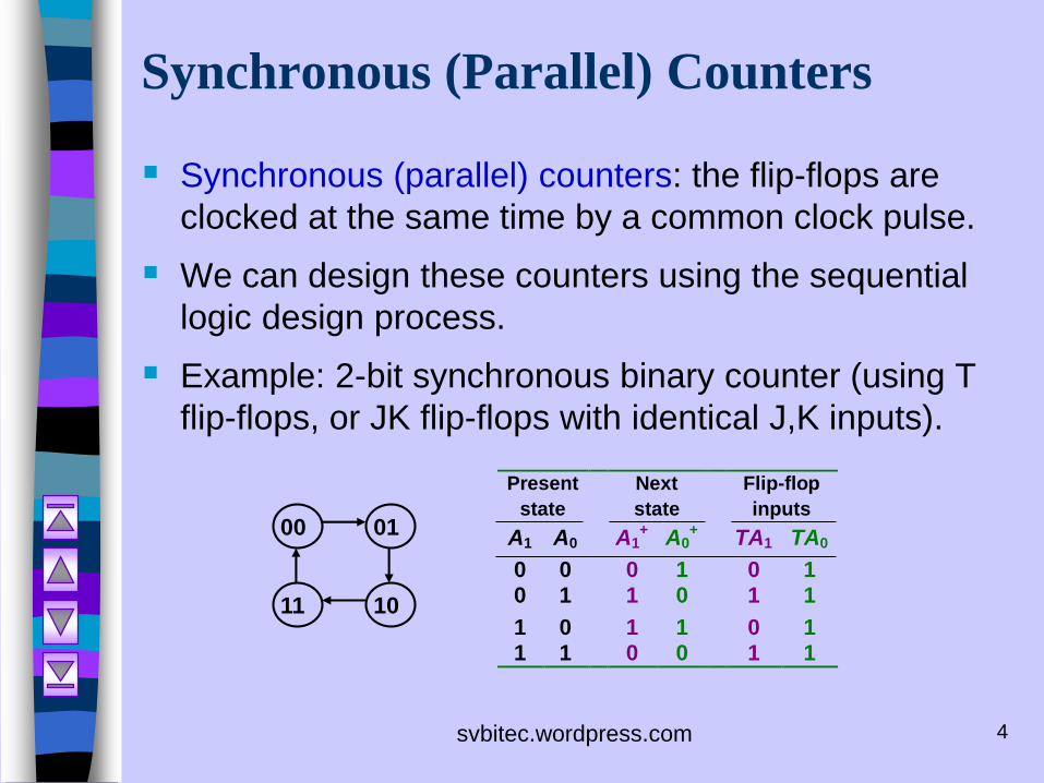
Synchronous (parallel) counters: the flip-flops are
clocked at the same time by a common clock pulse.
We can design these counters using the sequential
logic design process.
Example: 2-bit synchronous binary counter (using T
flip-flops, or JK flip-flops with identical J,K inputs).
Present Next Flip-flop
state state inputs
A1 A0 A1+
A0+
TA1 TA0
0 0 0 1 0 10 1 1 0 1 1
1 0 1 1 0 11 1 0 0 1 1
0100
1011
svbitec.wordpress.com 5
Synchronous (Parallel) Counters
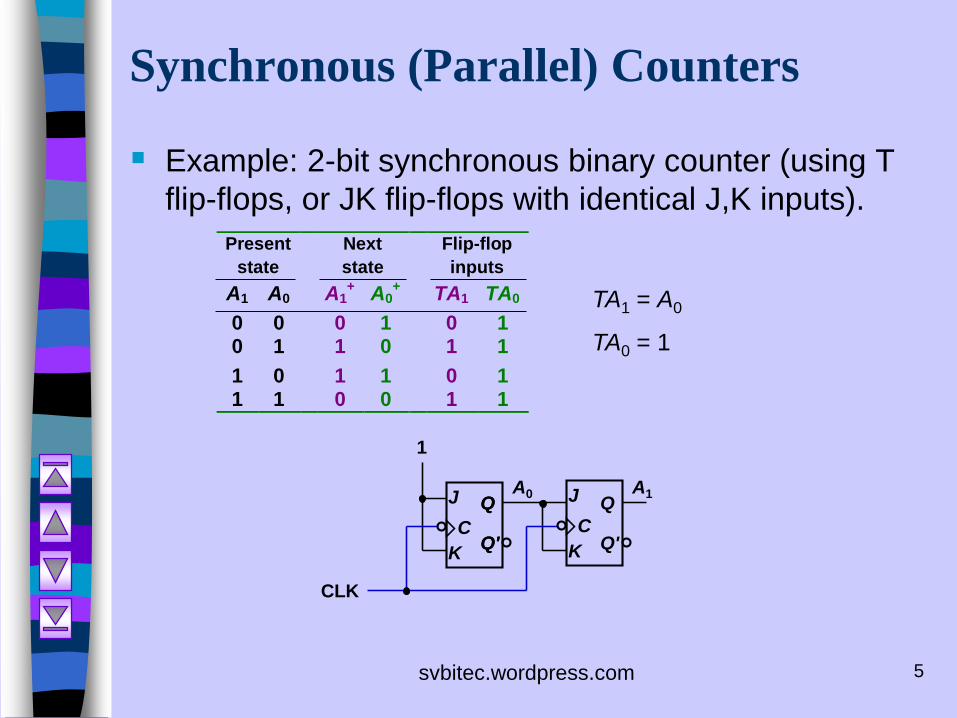
Example: 2-bit synchronous binary counter (using T
flip-flops, or JK flip-flops with identical J,K inputs).
Present Next Flip-flop
state state inputs
A1 A0 A1+
A0+
TA1 TA0
0 0 0 1 0 10 1 1 0 1 1
1 0 1 1 0 11 1 0 0 1 1
TA1 = A0
TA0 = 1
1
K
J
K
J A1A0
CC
CLK
Q
Q'
Q
Q'
Q
Q'
svbitec.wordpress.com 6
Synchronous (Parallel) Counters
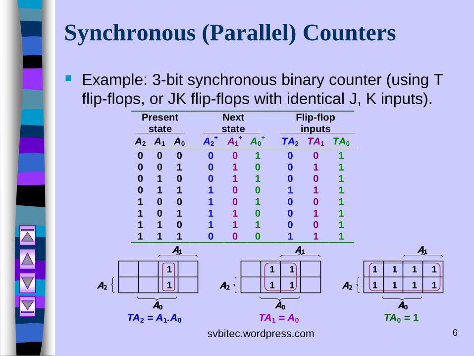
Example: 3-bit synchronous binary counter (using T
flip-flops, or JK flip-flops with identical J, K inputs).Present Next Flip-flop
state state inputs
A2 A1 A0 A2+
A1+
A0+
TA2 TA1 TA0
0 0 0 0 0 1 0 0 10 0 1 0 1 0 0 1 10 1 0 0 1 1 0 0 10 1 1 1 0 0 1 1 1
1 0 0 1 0 1 0 0 11 0 1 1 1 0 0 1 11 1 0 1 1 1 0 0 11 1 1 0 0 0 1 1 1
TA2 = A1.A0
A2
A1
A0
1
1
TA1 = A0 TA0 = 1
A2
A1
A0
1
1 1
1
A2
A1
A0
1 1 1
11 1 1
1
svbitec.wordpress.com 7
Synchronous (Parallel) Counters
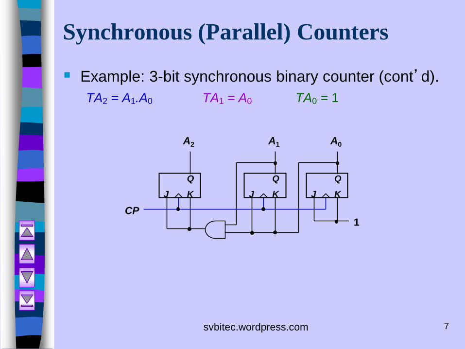
Example: 3-bit synchronous binary counter (cont’d).
TA2 = A1.A0 TA1 = A0 TA0 = 1
1
A2
CP
A1 A0
K
Q
J K
Q
J K
Q
J
svbitec.wordpress.com 8
Synchronous (Parallel) Counters
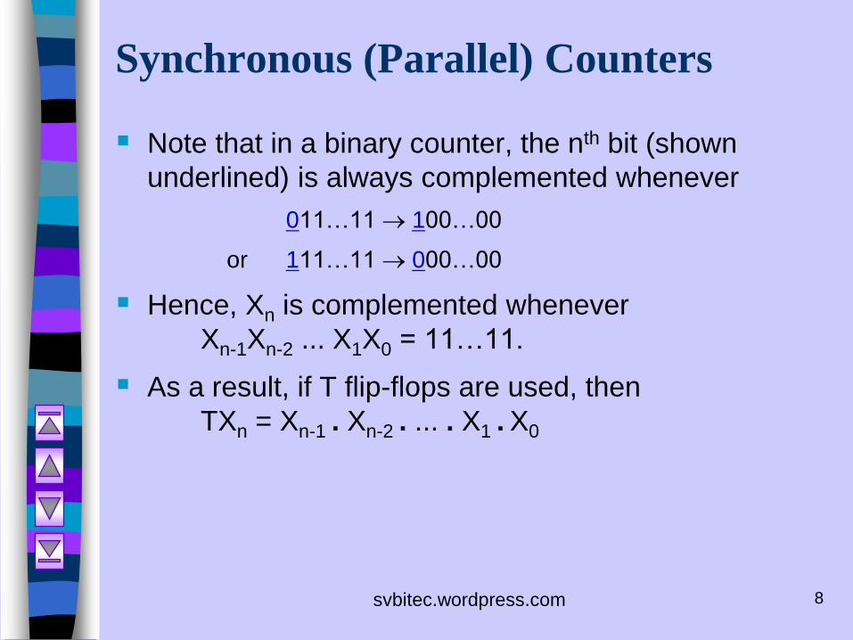
Note that in a binary counter, the nth bit (shown
underlined) is always complemented whenever
011…11 100…00
or 111…11 000…00
Hence, Xn is complemented whenever
Xn-1Xn-2 ... X1X0 = 11…11.
As a result, if T flip-flops are used, then
TXn = Xn-1 . Xn-2 . ... . X1 . X0
svbitec.wordpress.com 9
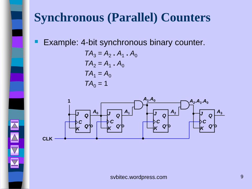
Synchronous (Parallel) Counters
Example: 4-bit synchronous binary counter.
TA3 = A2 . A1 . A0
TA2 = A1 . A0
TA1 = A0
TA0 = 1
1
K
J
K
J A1A0
CC
CLK
Q
Q'
Q
Q'
Q
Q' K
J A2
C
Q
Q' K
J A3
C
Q
Q'
A1.A0 A2.A1.A0
svbitec.wordpress.com 10
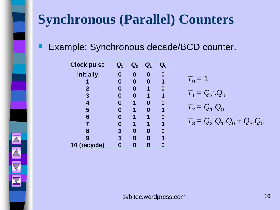
Synchronous (Parallel) Counters
Example: Synchronous decade/BCD counter.
Clock pulse Q3 Q2 Q1 Q0
Initially 0 0 0 01 0 0 0 12 0 0 1 03 0 0 1 1
4 0 1 0 05 0 1 0 16 0 1 1 07 0 1 1 18 1 0 0 09 1 0 0 1
10 (recycle) 0 0 0 0
T0 = 1
T1 = Q3'.Q0
T2 = Q1.Q0
T3 = Q2.Q1.Q0 + Q3.Q0
svbitec.wordpress.com 11
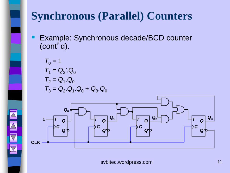
Synchronous (Parallel) Counters
Example: Synchronous decade/BCD counter (cont’d).
T0 = 1
T1 = Q3'.Q0
T2 = Q1.Q0
T3 = Q2.Q1.Q0 + Q3.Q0
1 Q1
Q0
CLK
T
C
Q
Q'
Q
Q'
Q2 Q3T
C
Q
Q'
Q
Q'
T
C
Q
Q'
Q
Q'
T
C
Q
Q'
Q
Q'
svbitec.wordpress.com 12
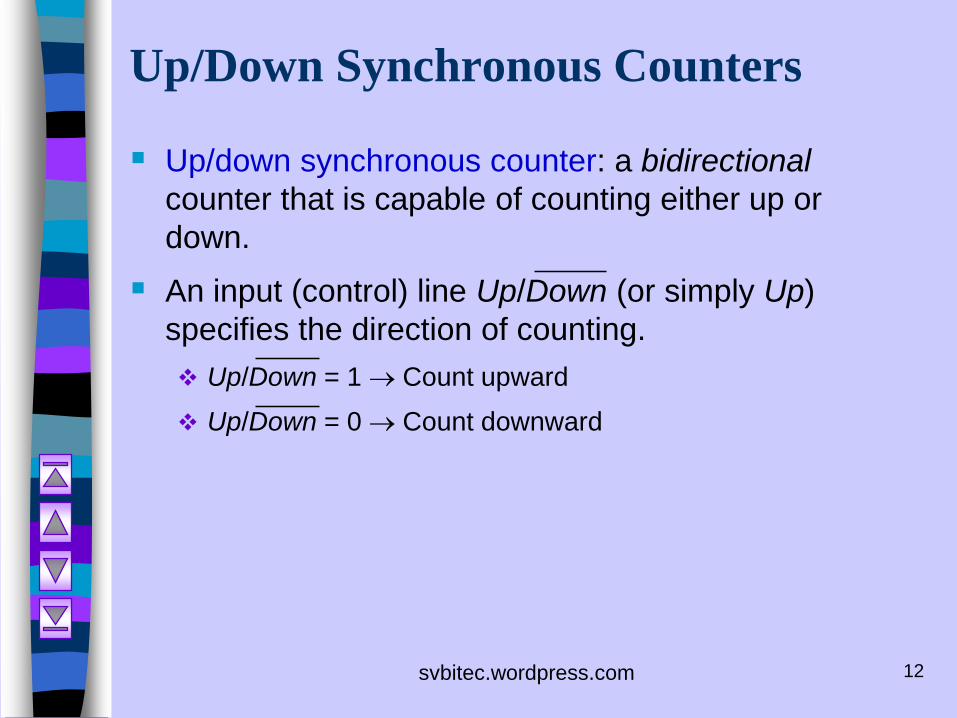
Up/Down Synchronous Counters
Up/down synchronous counter: a bidirectional
counter that is capable of counting either up or
down.
An input (control) line Up/Down (or simply Up)
specifies the direction of counting.
Up/Down = 1 Count upward
Up/Down = 0 Count downward
svbitec.wordpress.com 13
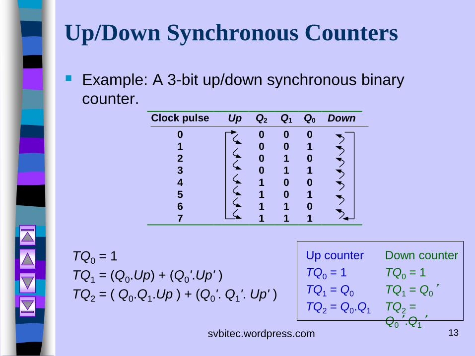
Up/Down Synchronous Counters
Example: A 3-bit up/down synchronous binary
counter.Clock pulse Up Q2 Q1 Q0 Down
0 0 0 01 0 0 12 0 1 03 0 1 1
4 1 0 05 1 0 16 1 1 07 1 1 1
TQ0 = 1
TQ1 = (Q0.Up) + (Q0'.Up' )
TQ2 = ( Q0.Q1.Up ) + (Q0'. Q1'. Up' )
Up counter
TQ0 = 1
TQ1 = Q0
TQ2 = Q0.Q1
Down counter
TQ0 = 1
TQ1 = Q0’
TQ2 =
Q0’.Q1’
svbitec.wordpress.com 14
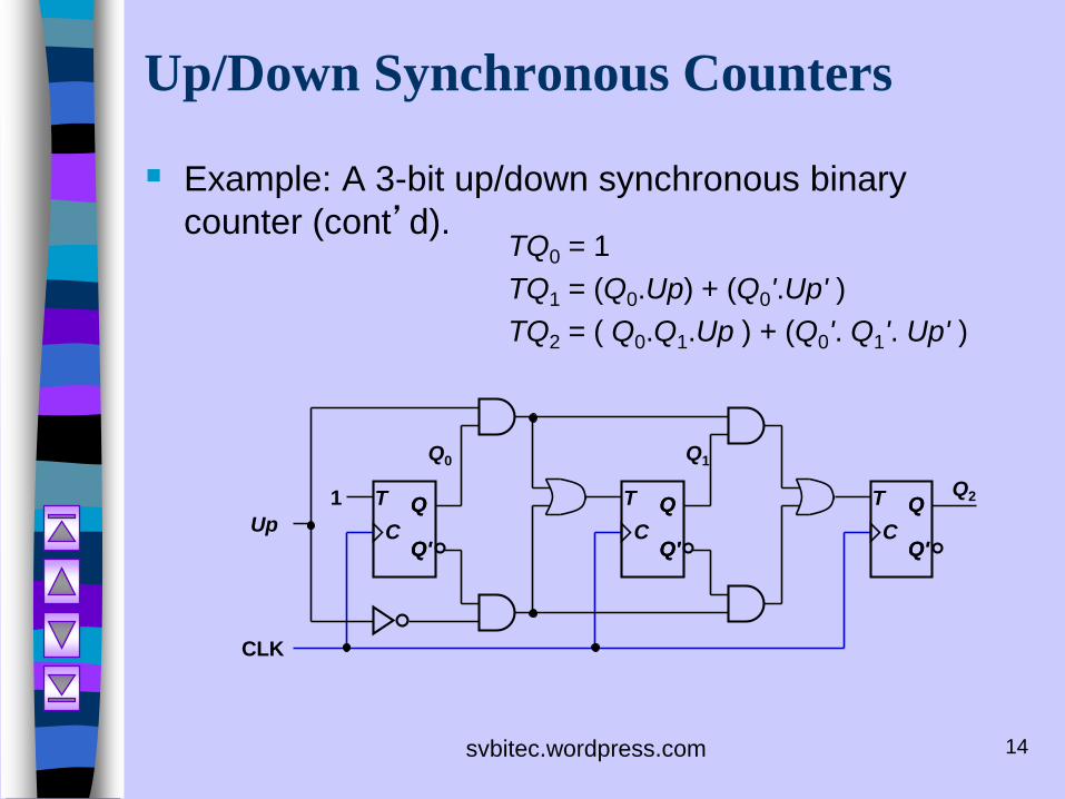
Up/Down Synchronous Counters
Example: A 3-bit up/down synchronous binary
counter (cont’d).TQ0 = 1
TQ1 = (Q0.Up) + (Q0'.Up' )
TQ2 = ( Q0.Q1.Up ) + (Q0'. Q1'. Up' )
1
Q1Q0
CLK
T
C
Q
Q'
Q
Q'
T
C
Q
Q'
Q
Q'
T
C
Q
Q'
Q
Q'
Up
Q2
svbitec.wordpress.com 15
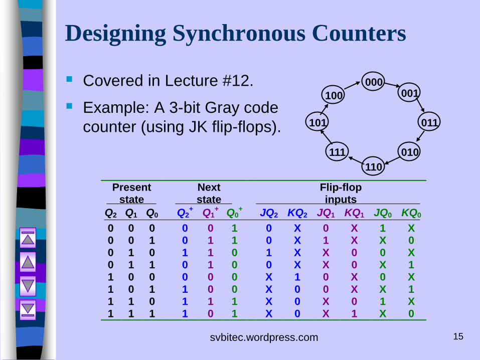
Designing Synchronous Counters
Covered in Lecture #12.
Example: A 3-bit Gray code
counter (using JK flip-flops).
100
000001
101
111
110
011
010
Present Next Flip-flopstate state inputs
Q2 Q1 Q0 Q2+
Q1+
Q0+
JQ2 KQ2 JQ1 KQ1 JQ0 KQ0
0 0 0 0 0 1 0 X 0 X 1 X0 0 1 0 1 1 0 X 1 X X 00 1 0 1 1 0 1 X X 0 0 X0 1 1 0 1 0 0 X X 0 X 11 0 0 0 0 0 X 1 0 X 0 X1 0 1 1 0 0 X 0 0 X X 11 1 0 1 1 1 X 0 X 0 1 X1 1 1 1 0 1 X 0 X 1 X 0
svbitec.wordpress.com 16
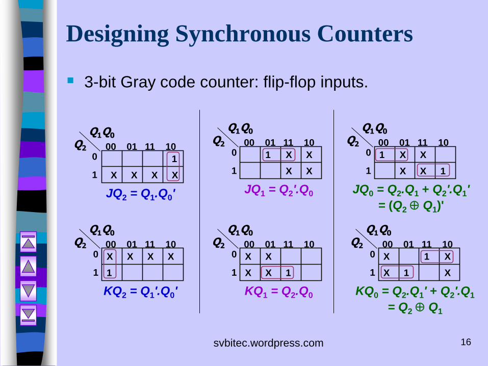
Designing Synchronous Counters
3-bit Gray code counter: flip-flop inputs.
0
1
00 01 11 10Q2
Q1Q0
X X X X
1
JQ2 = Q1.Q0'
0
1
00 01 11 10Q2
Q1Q0
X X X X
1
KQ2 = Q1'.Q0'
0
1
00 01 11 10Q2
Q1Q0
X X
X X1
JQ1 = Q2'.Q0
0
1
00 01 11 10Q2
Q1Q0
X X
X X
1
KQ1 = Q2.Q0
0
1
00 01 11 10Q2
Q1Q0
XX
XX1
JQ0 = Q2.Q1 + Q2'.Q1'
= (Q2 Q1)'
1
0
1
00 01 11 10Q2
Q1Q0
XX
XX 1
1
KQ0 = Q2.Q1' + Q2'.Q1
= Q2 Q1
svbitec.wordpress.com 17
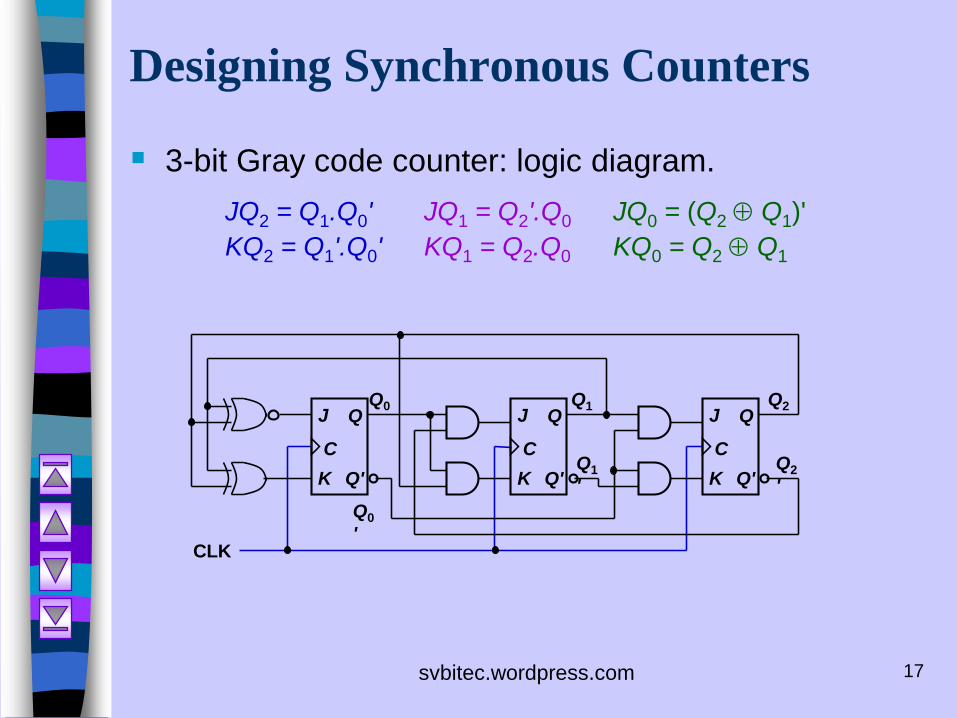
Designing Synchronous Counters
3-bit Gray code counter: logic diagram.
JQ2 = Q1.Q0' JQ1 = Q2'.Q0 JQ0 = (Q2 Q1)'
KQ2 = Q1'.Q0' KQ1 = Q2.Q0 KQ0 = Q2 Q1
Q1Q0
CLK
Q2J
C
Q
Q'K
J
C
Q
Q'K
J
C
Q
Q'KQ2
'
Q0
'
Q1
'