carrier ethernet and ethernet oam
TRANSCRIPT
© 2007 Cisco Systems, Inc. All rights reserved. Cisco Confidential 1
Carrier Ethernet and Ethernet OAM
Santanu Dasgupta ([email protected])
Dhaka, 29th January 2010
© 2007 Cisco Systems, Inc. All rights reserved. 2
House Rules
Please put your mobile phones into silent mode.
Kindly do not take calls inside of this room while the session is going on.
Your feedback on the session is extremely important!
© 2007 Cisco Systems, Inc. All rights reserved. 3
Assumptions
You have a good understanding Ethernet Switching and some basic understanding of Carrier-E technology
You have some general understanding of OAM.
You will be awake throughout the presentation!
© 2007 Cisco Systems, Inc. All rights reserved. 4
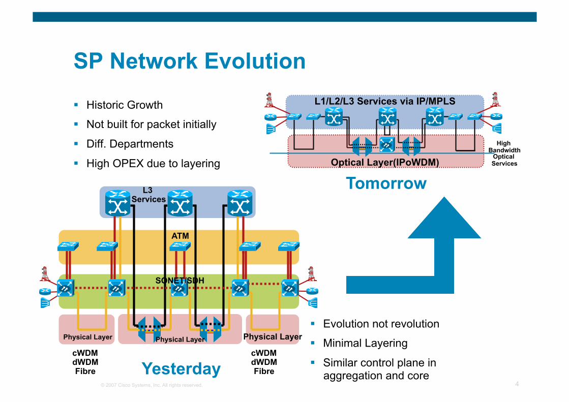
SP Network Evolution
Historic Growth
Not built for packet initially
Diff. Departments
High OPEX due to layering
Evolution not revolution
Minimal Layering
Similar control plane in aggregation and core
Physical Layer
ATM
Physical Layer
cWDM dWDM Fibre
cWDM dWDM Fibre Yesterday
L3 Services
Physical Layer
SONET/SDH
Optical Layer(IPoWDM)
L1/L2/L3 Services via IP/MPLS
High Bandwidth
Optical Services
Tomorrow
© 2007 Cisco Systems, Inc. All rights reserved. 5
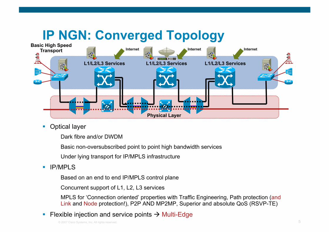
IP NGN: Converged Topology
Optical layer Dark fibre and/or DWDM
Basic non-oversubscribed point to point high bandwidth services
Under lying transport for IP/MPLS infrastructure
IP/MPLS Based on an end to end IP/MPLS control plane
Concurrent support of L1, L2, L3 services
MPLS for ‘Connection oriented’ properties with Traffic Engineering, Path protection (and Link and Node protection!), P2P AND MP2MP, Superior and absolute QoS (RSVP-TE)
Flexible injection and service points Multi-Edge
Physical Layer
L1/L2/L3 Services
Internet
L1/L2/L3 Services
Internet
L1/L2/L3 Services
Internet Basic High Speed
Transport
© 2007 Cisco Systems, Inc. All rights reserved. 6
Carrier Ethernet : Agenda
Business Connectivity—The Landscape
Why Ethernet? The Evolution
Carrier Ethernet— Technology Primer
Carrier Ethernet Services Flow
Ethernet OAM
© 2007 Cisco Systems, Inc. All rights reserved. 7
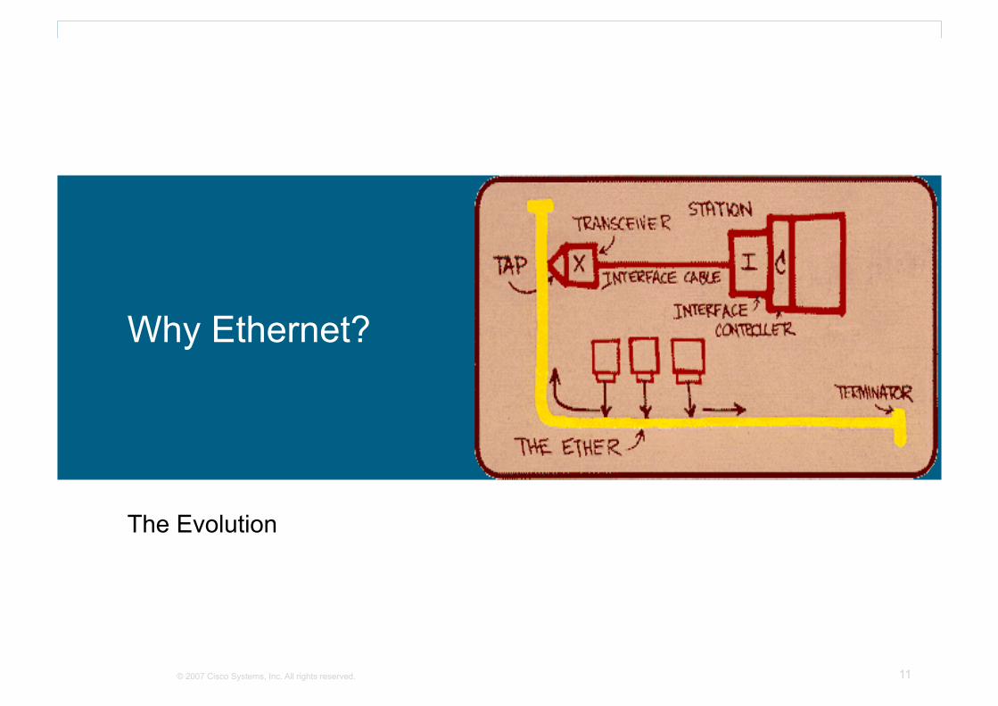
Once Upon a Long Ago…
1972 Dr Robert Metcalfe implemented the Alto Aloha Network at Xerox Parc
1976 The name Ethernet was first used
© 2007 Cisco Systems, Inc. All rights reserved. 8
Business Connectivity – The Landscape
© 2007 Cisco Systems, Inc. All rights reserved. 9
Business Connectivity
Geographically diverse business locations
Distributed applications require LAN extension
Multiple customers over a single infrastructure
Killer applications driving next generation Layer 2 VPNs
Active/Active or Active/Backup resiliency configurations
The Landscape
© 2007 Cisco Systems, Inc. All rights reserved. 10
Site-to-Site Connectivity
L2VPNs must evolve
Ethernet: The next step
Ethernet provides More bandwidth than traditional L2VPNs
True LAN extension between remote areas
Customer Ethernet connected via SP Ethernet
BFD with MPLS Fast ReRoute can minimize downtime
Multiple redundancy models can be deployed
The Answer: Carrier Ethernet
© 2007 Cisco Systems, Inc. All rights reserved. 11
Why Ethernet?
The Evolution
© 2007 Cisco Systems, Inc. All rights reserved. 12
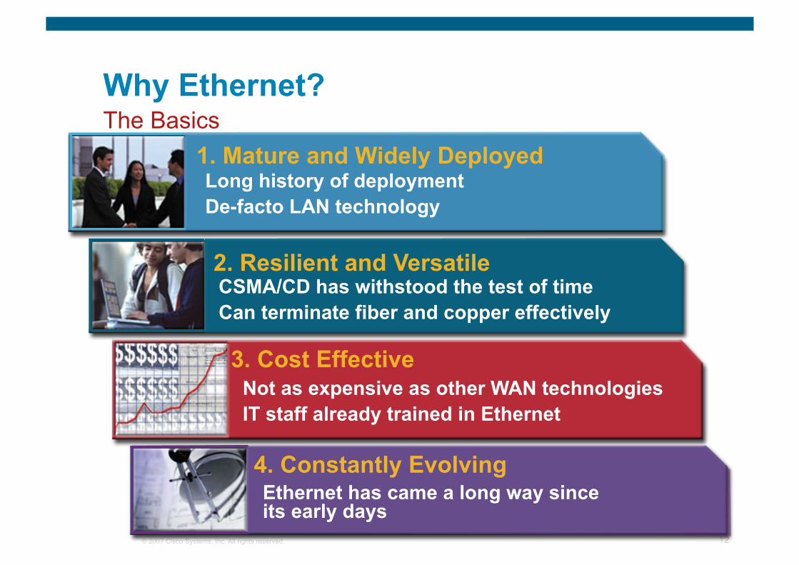
Why Ethernet? The Basics
1. Mature and Widely Deployed Long history of deployment De-facto LAN technology
2. Resilient and Versatile CSMA/CD has withstood the test of time Can terminate fiber and copper effectively
Not as expensive as other WAN technologies IT staff already trained in Ethernet
3. Cost Effective
4. Constantly Evolving Ethernet has came a long way since its early days
© 2007 Cisco Systems, Inc. All rights reserved. 13
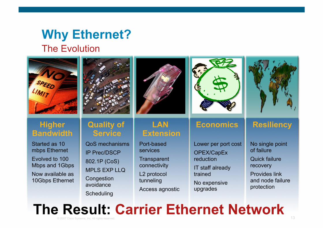
Why Ethernet? The Evolution
Higher Bandwidth Started as 10 mbps Ethernet Evolved to 100 Mbps and 1Gbps Now available as 10Gbps Ethernet
Quality of Service
QoS mechanisms IP Prec/DSCP 802.1P (CoS) MPLS EXP LLQ Congestion avoidance Scheduling
LAN Extension
Port-based services Transparent connectivity L2 protocol tunneling Access agnostic
Economics
Lower per port cost OPEX/CapEx reduction IT staff already trained No expensive upgrades
Resiliency
No single point of failure Quick failure recovery Provides link and node failure protection
The Result: Carrier Ethernet Network

© 2007 Cisco Systems, Inc. All rights reserved. 14
Carrier Ethernet
An Overview
© 2007 Cisco Systems, Inc. All rights reserved. 15
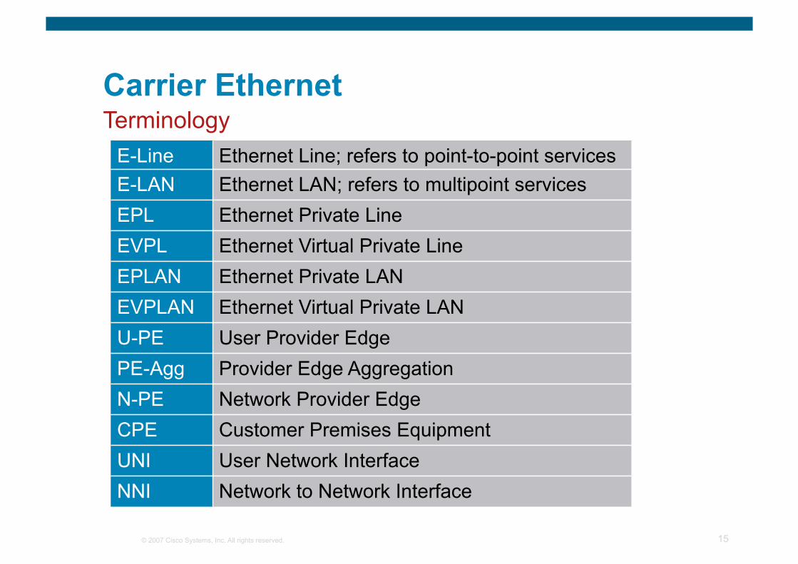
Carrier Ethernet
E-Line Ethernet Line; refers to point-to-point services E-LAN Ethernet LAN; refers to multipoint services EPL Ethernet Private Line EVPL Ethernet Virtual Private Line EPLAN Ethernet Private LAN EVPLAN Ethernet Virtual Private LAN U-PE User Provider Edge PE-Agg Provider Edge Aggregation N-PE Network Provider Edge CPE Customer Premises Equipment UNI User Network Interface NNI Network to Network Interface
Terminology
© 2007 Cisco Systems, Inc. All rights reserved. 16
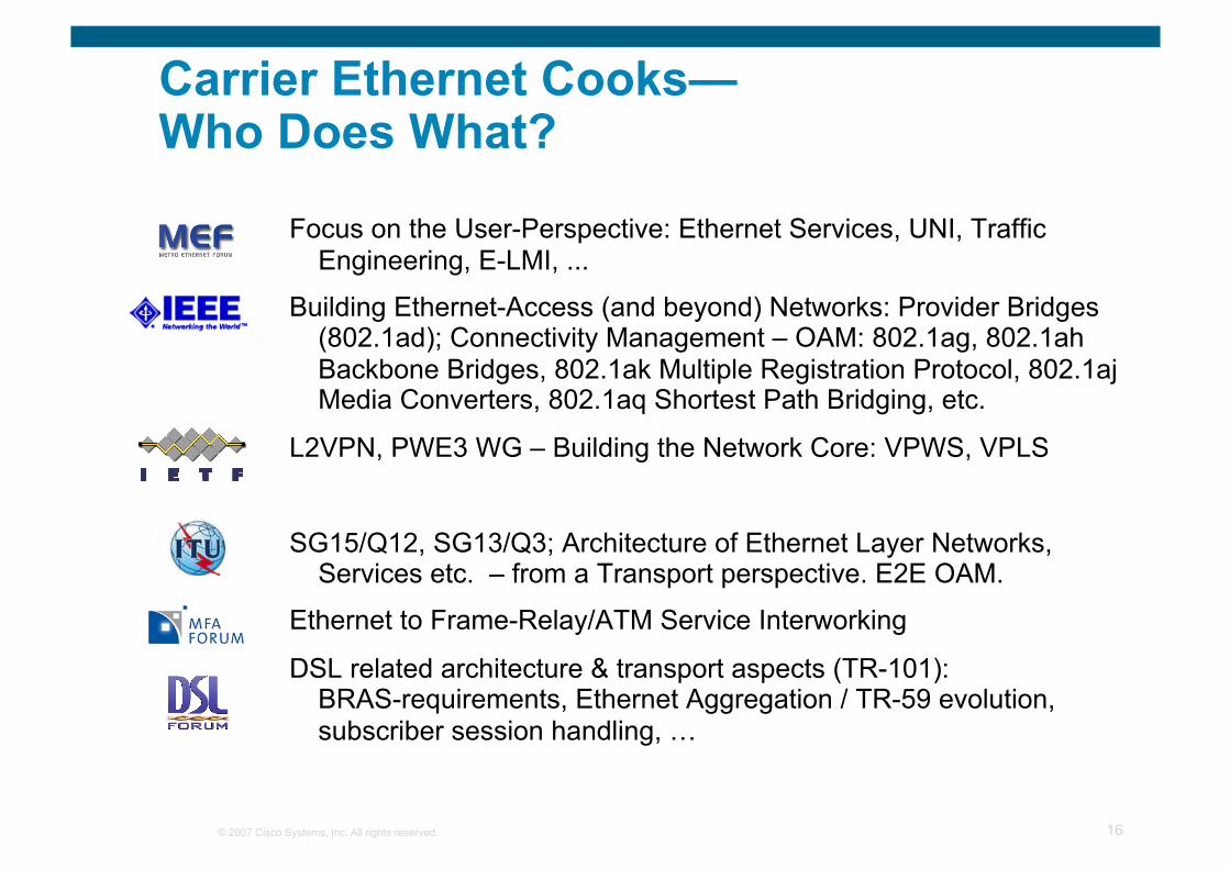
Carrier Ethernet Cooks— Who Does What?
Focus on the User-Perspective: Ethernet Services, UNI, Traffic Engineering, E-LMI, ...
Building Ethernet-Access (and beyond) Networks: Provider Bridges (802.1ad); Connectivity Management – OAM: 802.1ag, 802.1ah Backbone Bridges, 802.1ak Multiple Registration Protocol, 802.1aj Media Converters, 802.1aq Shortest Path Bridging, etc.
L2VPN, PWE3 WG – Building the Network Core: VPWS, VPLS
SG15/Q12, SG13/Q3; Architecture of Ethernet Layer Networks, Services etc. – from a Transport perspective. E2E OAM.
Ethernet to Frame-Relay/ATM Service Interworking
DSL related architecture & transport aspects (TR-101): BRAS-requirements, Ethernet Aggregation / TR-59 evolution, subscriber session handling, …
© 2007 Cisco Systems, Inc. All rights reserved. 17
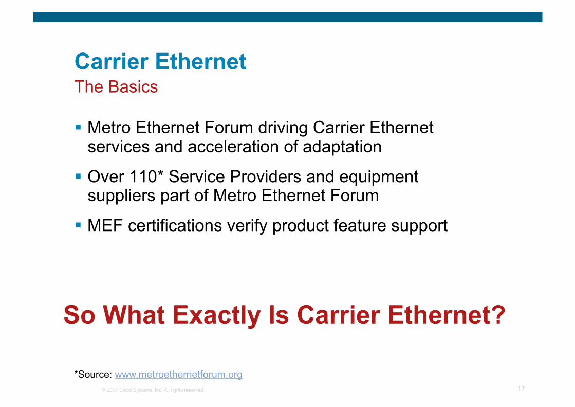
Carrier Ethernet
Metro Ethernet Forum driving Carrier Ethernet services and acceleration of adaptation
Over 110* Service Providers and equipment suppliers part of Metro Ethernet Forum
MEF certifications verify product feature support
So What Exactly Is Carrier Ethernet?
The Basics
*Source: www.metroethernetforum.org

© 2007 Cisco Systems, Inc. All rights reserved. Cisco Confidential 18
“Carrier Ethernet is a ubiquitous, standardized, carrier-class SERVICE defined by five attributes that distinguish Carrier Ethernet from familiar LAN based Ethernet.”
© 2007 Cisco Systems, Inc. All rights reserved. 19
Carrier Ethernet
Standardized Services Point-to-point (E-LINE) and multipoint (E-LAN) services
Does not require any changes to customer LAN equipment
Scalability Bandwidth scalability from 1mbps up to 10gbps
Large number of customers over a common infrastructure
Reliability Failure detection and recovery without customer impact
50msec or less convergence for sensitive traffic
Service Attributes
© 2007 Cisco Systems, Inc. All rights reserved. 20
Carrier Ethernet
Quality of Service Provide a range of Bandwidth and Quality of Service options
Multiple classes of traffic with guaranteed Service Level Agreements (SLA)
Service Management Central monitoring and management stations
User friendly service provisioning
Service Attributes
© 2007 Cisco Systems, Inc. All rights reserved. 21
Carrier Ethernet
Network convergence IP over Ethernet as enabling technologies for “One” Network
CAPEX and OPEX reductions
Flexible Service Offerings Customized solutions
Flexible mix of services and data rates (EPL, EVPL, E-LAN)
Ubiquitous Access Access networks that leverage Ethernet
PON, Wimax, IP DSLAMs, Ethernet over Fiber, Ethernet over Copper, etc.
Service Provider Perspective
© 2007 Cisco Systems, Inc. All rights reserved. 22
Carrier Ethernet
Standardization Products must go through certification
MEF certification tests are conducted to meet service requirements
Box-Level Economics Ethernet equipment is already widely deployed
Less expensive than ATM or SONET/SDH
Service Provider Perspective
© 2007 Cisco Systems, Inc. All rights reserved. 23
Carrier Ethernet
Network Convergence One network for all Business applications
Cost reductions
Virtualization High speed, low latency VPNs
Extend LAN–MAN–WAN without protocol conversion
Operational Benefits Ethernet is very familiar to IT staffs
Enterprise Customer Perspective
© 2007 Cisco Systems, Inc. All rights reserved. 24
Carrier Ethernet
Simple Upgrades Ethernet delivers bandwidth up to 10 Gbps (and beyond)
Easier Incremental bandwidth upgrades
Standardization User-to-Network Interface (UNI) everywhere in the networks
Reduced spares inventories, training, management and testing tools
Enterprise Customer Perspective
© 2007 Cisco Systems, Inc. All rights reserved. 25
Carrier Ethernet
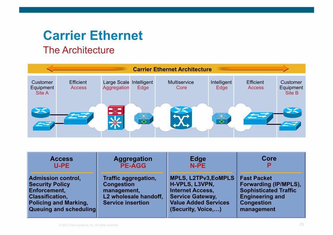
Carrier Ethernet Architecture
Core P
Fast Packet Forwarding (IP/MPLS), Sophisticated Traffic Engineering and Congestion management
Aggregation PE-AGG
Traffic aggregation, Congestion management, L2 wholesale handoff, Service insertion
Access U-PE
Admission control, Security Policy Enforcement, Classification, Policing and Marking, Queuing and scheduling
Edge N-PE
MPLS, L2TPv3,EoMPLS H-VPLS, L3VPN, Internet Access, Service Gateway, Value Added Services (Security, Voice,…)
The Architecture
Large Scale Aggregation
Intelligent Edge
Multiservice Core
Efficient Access
Intelligent Edge
Efficient Access
Customer Equipment
Site A
Customer Equipment
Site B
© 2007 Cisco Systems, Inc. All rights reserved. 26
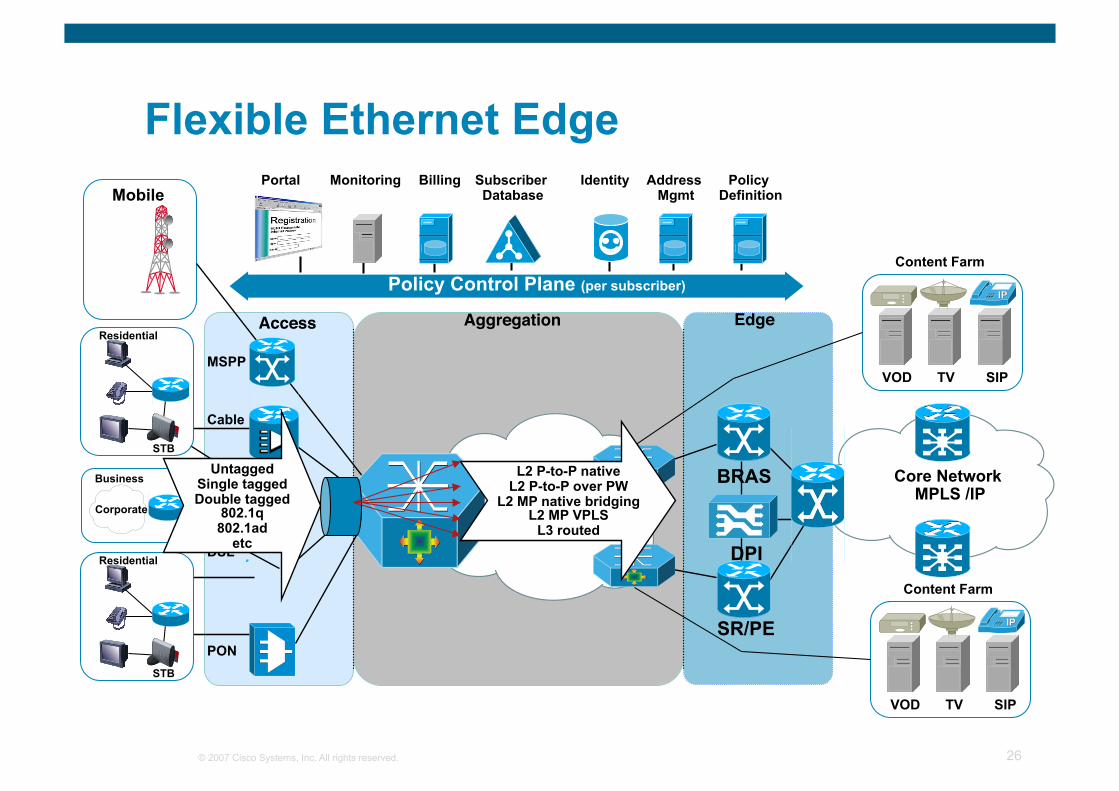
Access Edge
BRAS
SR/PE
DPI
Core Network MPLS /IP
Identity Address Mgmt
Portal Subscriber Database
Monitoring Policy Definition
Billing
Content Farm
VOD TV SIP
DSL Residential
STB
Content Farm
VOD TV SIP
Mobile
ETTx
PON
MSPP
Cable
Business
Corporate
Residential
STB
Policy Control Plane (per subscriber)
Aggregation
L2 P-to-P native L2 P-to-P over PW
L2 MP native bridging L2 MP VPLS
L3 routed
Untagged Single tagged Double tagged
802.1q 802.1ad
etc
Flexible Ethernet Edge
© 2007 Cisco Systems, Inc. All rights reserved. 27
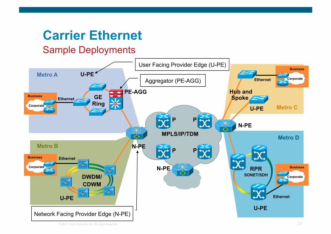
Carrier Ethernet
Sample Deployments
GE Ring
Metro A
Ethernet
MPLS/IP/TDM
N-PE
N-PE
N-PE P P
P P
U-PE
PE-AGG
Metro C U-PE
U-PE
RPR SONET/SDH
Metro D
Network Facing Provider Edge (N-PE)
U-PE
DWDM/ CDWM
Metro B
Ethernet
Hub and Spoke
User Facing Provider Edge (U-PE)
Ethernet
Ethernet
Business
Corporate
Aggregator (PE-AGG)
Business
Corporate
Business
Corporate
Business
Corporate
© 2007 Cisco Systems, Inc. All rights reserved. 28
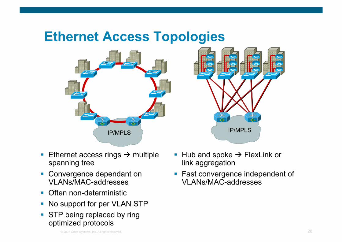
Ethernet Access Topologies
Ethernet access rings multiple spanning tree
Convergence dependant on VLANs/MAC-addresses
Often non-deterministic No support for per VLAN STP STP being replaced by ring
optimized protocols
Hub and spoke FlexLink or link aggregation
Fast convergence independent of VLANs/MAC-addresses
IP/MPLS IP/MPLS
© 2007 Cisco Systems, Inc. All rights reserved. 29
Resilient Ethernet Protocol
Large spanning-tree domain
Carrier Ethernet trend Fast convergence requirements
Spanning tree not perceived as carrier-class
Complexity of management and troubleshooting of STP
REP addresses these issues
Problem Statement
© 2007 Cisco Systems, Inc. All rights reserved. 30
What Is REP?
A new protocol designed to provide a solution for fast and predicable Layer 2 convergence for carrier Ethernet networks
Fast and predictable convergence Convergence time: 50 to 250 ms Fast failure notification even in large rings
Limit the scope of spanning tree STP is deactivated on REP interfaces
Allows VLAN load balancing for optimal bandwidth utilization
Cisco proprietary (so far, future alignment with ITU-T G.8032)

© 2007 Cisco Systems, Inc. All rights reserved. 31
Carrier Ethernet Services
© 2007 Cisco Systems, Inc. All rights reserved. 32
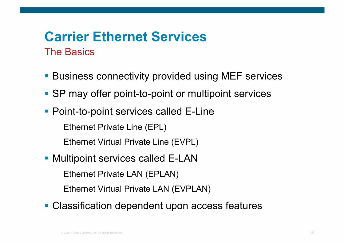
Carrier Ethernet Services
Business connectivity provided using MEF services
SP may offer point-to-point or multipoint services
Point-to-point services called E-Line Ethernet Private Line (EPL)
Ethernet Virtual Private Line (EVPL)
Multipoint services called E-LAN Ethernet Private LAN (EPLAN)
Ethernet Virtual Private LAN (EVPLAN)
Classification dependent upon access features
The Basics
© 2007 Cisco Systems, Inc. All rights reserved. 33
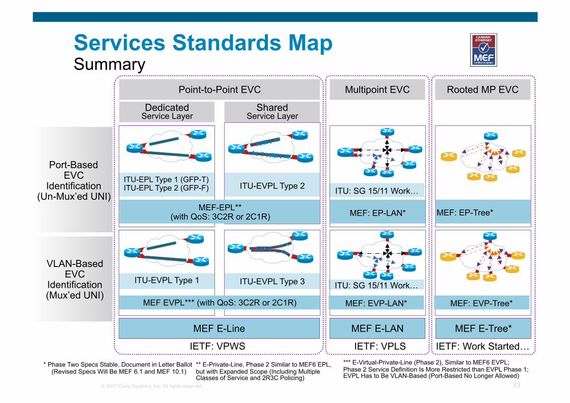
Services Standards Map Summary
MEF E-Line
Port-Based EVC
Identification (Un-Mux’ed UNI)
VLAN-Based EVC
Identification (Mux’ed UNI)
MEF E-LAN
Dedicated Service Layer
Point-to-Point EVC Multipoint EVC
IETF: VPWS IETF: VPLS
Shared Service Layer
Rooted MP EVC
ITU-EPL Type 1 (GFP-T) ITU-EPL Type 2 (GFP-F)
MEF EVPL*** (with QoS: 3C2R or 2C1R)
ITU-EVPL Type 1
ITU-EVPL Type 2
ITU-EVPL Type 3
* Phase Two Specs Stable, Document in Letter Ballot (Revised Specs Will Be MEF 6.1 and MEF 10.1)
ITU: SG 15/11 Work…
ITU: SG 15/11 Work…
IETF: Work Started… *** E-Virtual-Private-Line (Phase 2), Similar to MEF6 EVPL; Phase 2 Service Definition Is More Restricted than EVPL Phase 1; EVPL Has to Be VLAN-Based (Port-Based No Longer Allowed)
** E-Private-Line, Phase 2 Similar to MEF6 EPL, but with Expanded Scope (Including Multiple Classes of Service and 2R3C Policing)
MEF E-Tree*
MEF: EVP-LAN* MEF: EVP-Tree*
MEF: EP-LAN* MEF: EP-Tree* MEF-EPL** (with QoS: 3C2R or 2C1R)
© 2007 Cisco Systems, Inc. All rights reserved. 34
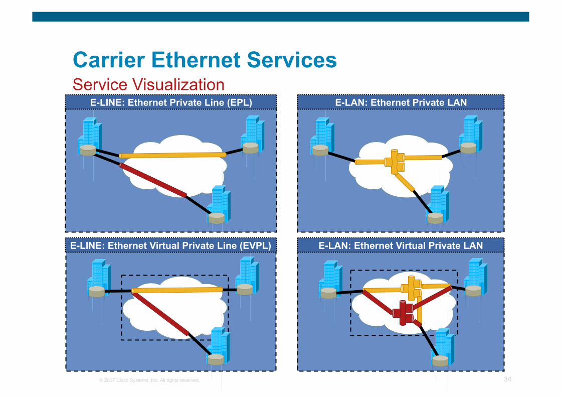
Carrier Ethernet Services
E-LINE: Ethernet Private Line (EPL) Service Visualization
E-LAN: Ethernet Private LAN
E-LINE: Ethernet Virtual Private Line (EVPL) E-LAN: Ethernet Virtual Private LAN
© 2007 Cisco Systems, Inc. All rights reserved. 35
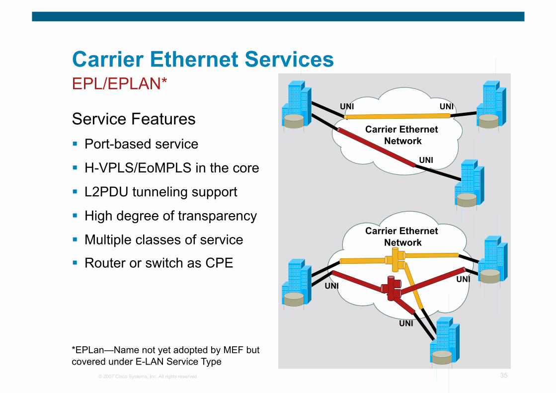
Carrier Ethernet Services
Service Features Port-based service
H-VPLS/EoMPLS in the core
L2PDU tunneling support
High degree of transparency
Multiple classes of service
Router or switch as CPE
Carrier Ethernet Network
UNI UNI
UNI
UNI UNI
UNI
Carrier Ethernet Network
EPL/EPLAN*
*EPLan—Name not yet adopted by MEF but covered under E-LAN Service Type

© 2007 Cisco Systems, Inc. All rights reserved. 36
Carrier Ethernet Services
Sample SP Offering Corporate/Campus LAN
Extension over WAN
Business Connectivity
Data Center
Network consolidation
EPL/EPLAN*
*EPLan—Name not yet adopted by MEF but covered under E-LAN Service Type
Carrier Ethernet Network
UNI UNI
UNI
UNI UNI
UNI
Carrier Ethernet Network
© 2007 Cisco Systems, Inc. All rights reserved. 37
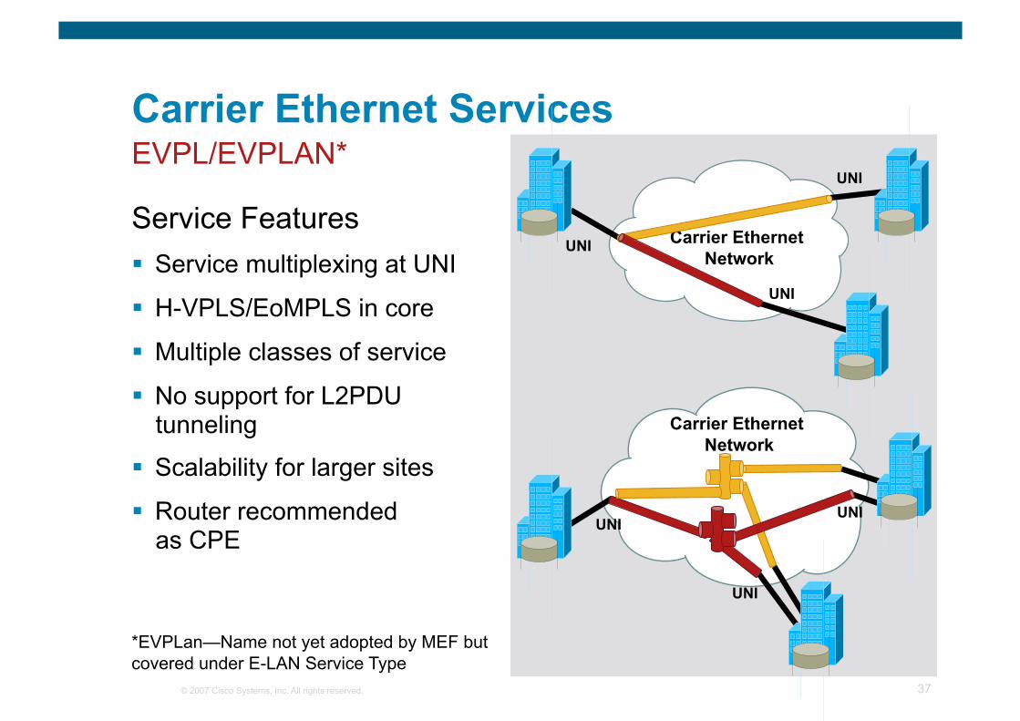
Carrier Ethernet Services
Service Features Service multiplexing at UNI
H-VPLS/EoMPLS in core
Multiple classes of service
No support for L2PDU tunneling
Scalability for larger sites
Router recommended as CPE
EVPL/EVPLAN*
*EVPLan—Name not yet adopted by MEF but covered under E-LAN Service Type
Carrier Ethernet Network
UNI
UNI
UNI
UNI UNI
UNI
Carrier Ethernet Network
© 2007 Cisco Systems, Inc. All rights reserved. 38
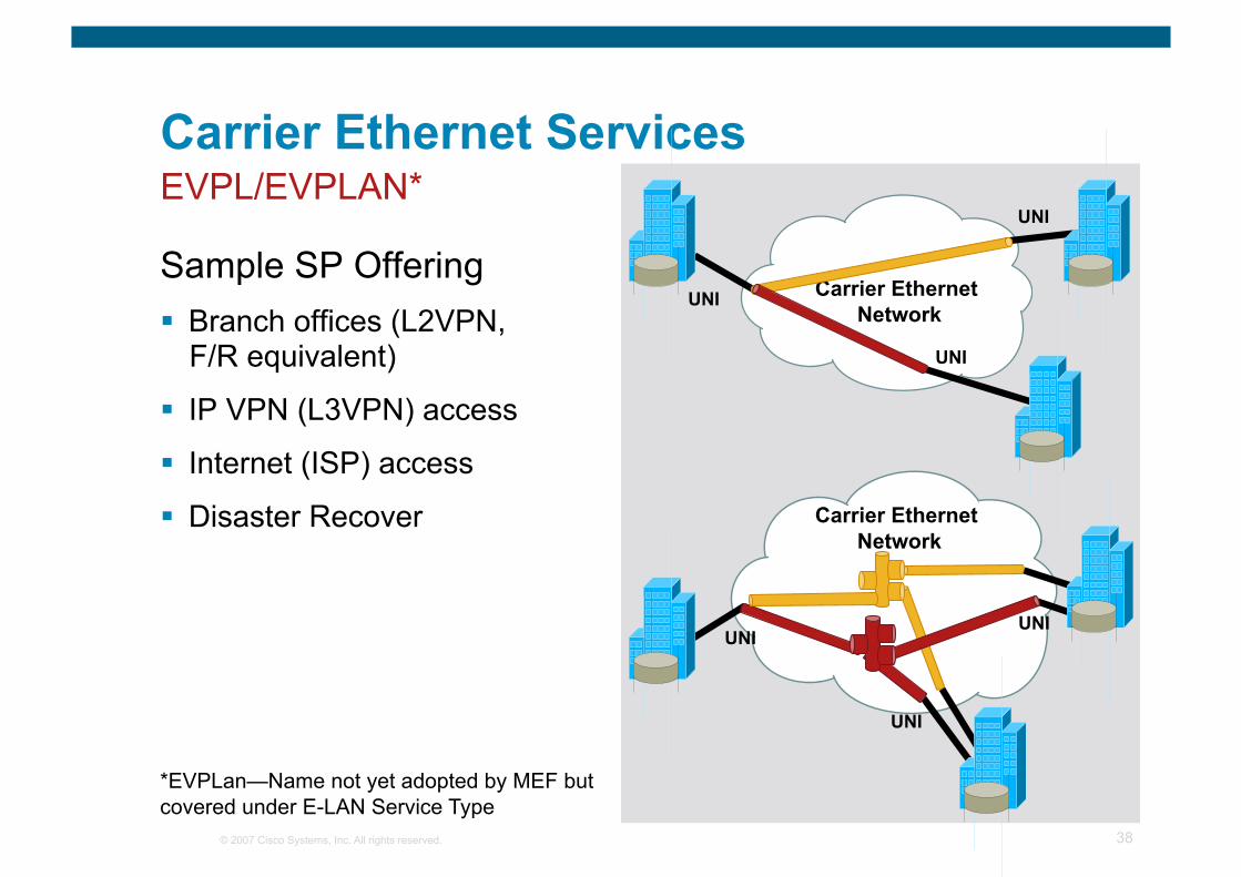
Carrier Ethernet Services
Sample SP Offering Branch offices (L2VPN,
F/R equivalent)
IP VPN (L3VPN) access
Internet (ISP) access
Disaster Recover
EVPL/EVPLAN*
*EVPLan—Name not yet adopted by MEF but covered under E-LAN Service Type
Carrier Ethernet Network
UNI
UNI
UNI
UNI UNI
UNI
Carrier Ethernet Network
© 2007 Cisco Systems, Inc. All rights reserved. 39
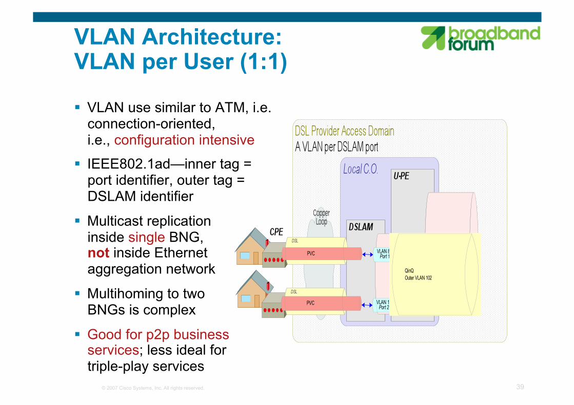
VLAN Architecture: VLAN per User (1:1)
VLAN use similar to ATM, i.e. connection-oriented, i.e., configuration intensive
IEEE802.1ad—inner tag = port identifier, outer tag = DSLAM identifier
Multicast replication inside single BNG, not inside Ethernet aggregation network
Multihoming to two BNGs is complex
Good for p2p business services; less ideal for triple-play services
© 2007 Cisco Systems, Inc. All rights reserved. 40
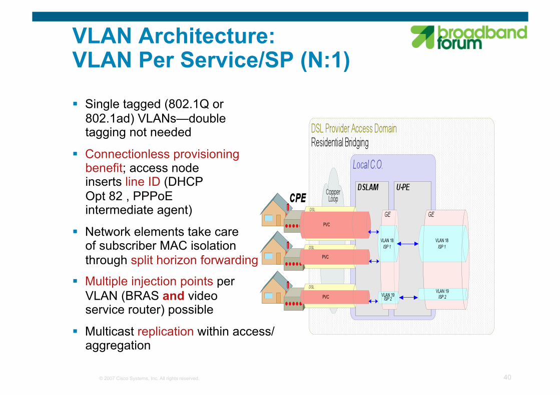
VLAN Architecture: VLAN Per Service/SP (N:1)
Single tagged (802.1Q or 802.1ad) VLANs—double tagging not needed
Connectionless provisioning benefit; access node inserts line ID (DHCP Opt 82 , PPPoE intermediate agent)
Network elements take care of subscriber MAC isolation through split horizon forwarding
Multiple injection points per VLAN (BRAS and video service router) possible
Multicast replication within access/aggregation
© 2007 Cisco Systems, Inc. All rights reserved. 41
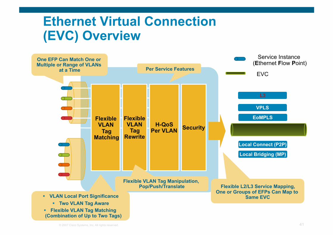
Flexible VLAN Tag
Matching
H-QoS Per VLAN
L3
EoMPLS VPLS
Local Connect (P2P)
Local Bridging (MP)
Security Flexible VLAN
Tag Rewrite
Service Instance (Ethernet Flow Point)
EVC
Ethernet Virtual Connection (EVC) Overview
One EFP Can Match One or Multiple or Range of VLANs
at a Time
Flexible L2/L3 Service Mapping, One or Groups of EFPs Can Map to
Same EVC
Per Service Features
VLAN Local Port Significance Two VLAN Tag Aware
Flexible VLAN Tag Matching (Combination of Up to Two Tags)
Flexible VLAN Tag Manipulation, Pop/Push/Translate
© 2007 Cisco Systems, Inc. All rights reserved. 42
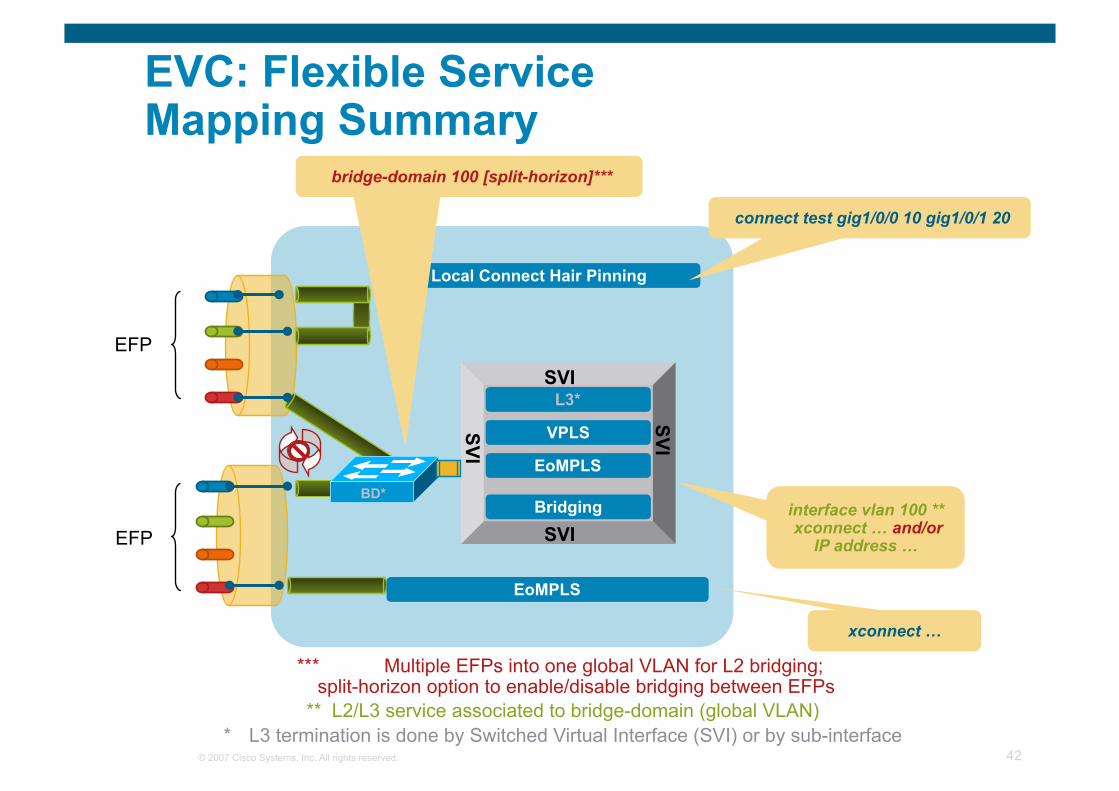
SVI
SVI
SVI
SVI
VPLS
Local Connect Hair Pinning
Bridging
EoMPLS
connect test gig1/0/0 10 gig1/0/1 20
xconnect …
interface vlan 100 ** xconnect … and/or
IP address …
L3*
bridge-domain 100 [split-horizon]***
EoMPLS
EFP
EFP
EVC: Flexible Service Mapping Summary
*** Multiple EFPs into one global VLAN for L2 bridging; split-horizon option to enable/disable bridging between EFPs
** L2/L3 service associated to bridge-domain (global VLAN) * L3 termination is done by Switched Virtual Interface (SVI) or by sub-interface
BD*
© 2007 Cisco Systems, Inc. All rights reserved. 43
Approaches for implementation
Control Plane & Forwarding Plane Options QinQ (With or without STP) Mac-in-Mac (With or without STP) IP/MPLS PBB-TE, T-MPLS, GMPLS …….
Basic idea is similar across the approach i.e. use the existing technologies to expand the scalability of existing “enterprise or services providers’ technologies” to handle large Ethernet networks
© 2007 Cisco Systems, Inc. All rights reserved. 44
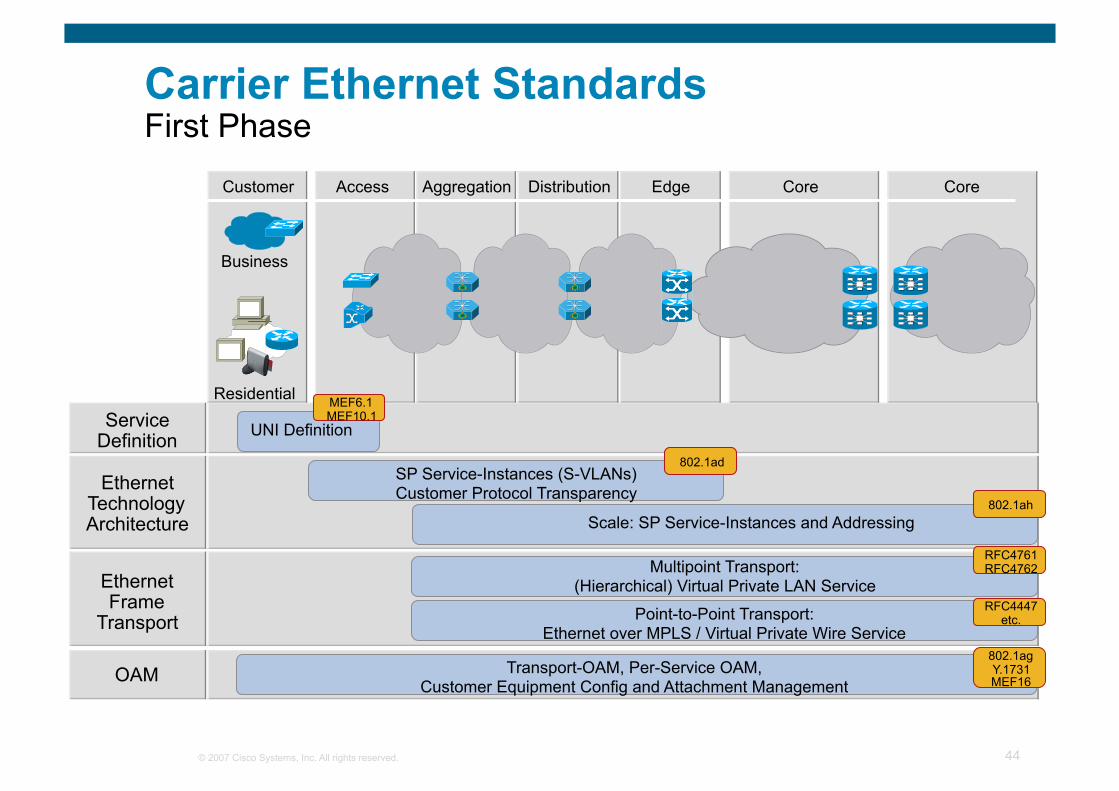
Carrier Ethernet Standards First Phase
SP Service-Instances (S-VLANs) Customer Protocol Transparency
UNI Definition
Scale: SP Service-Instances and Addressing
Service Definition
Ethernet Technology Architecture
Ethernet Frame
Transport
OAM
Point-to-Point Transport: Ethernet over MPLS / Virtual Private Wire Service
Multipoint Transport: (Hierarchical) Virtual Private LAN Service
Transport-OAM, Per-Service OAM, Customer Equipment Config and Attachment Management
MEF6.1 MEF10.1
802.1ad
802.1ah
RFC4761 RFC4762
RFC4447 etc.
802.1ag Y.1731 MEF16
Customer Access Aggregation Distribution Edge Core Core
Business
Residential
© 2007 Cisco Systems, Inc. All rights reserved. 45
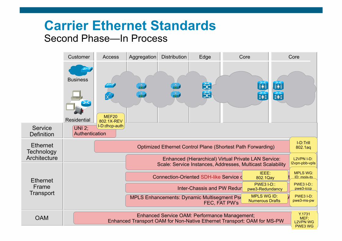
Carrier Ethernet Standards Second Phase—In Process
Business
Residential
Customer Access Aggregation Distribution Edge Core Core
Optimized Ethernet Control Plane (Shortest Path Forwarding)
UNI 2; Authentication
Service Definition
Ethernet Technology Architecture
Ethernet Frame
Transport
OAM Enhanced Service OAM: Performance Management; Enhanced Transport OAM for Non-Native Ethernet Transport: OAM for MS-PW
MPLS Enhancements: Dynamic Multisegment Pseudowires (MS-PW), Aggregate FEC, FAT PW’s
Enhanced (Hierarchical) Virtual Private LAN Service: Scale: Service Instances, Addresses, Multicast Scalability
Inter-Chassis and PW Redundancy
Connection-Oriented SDH-like Service over Packet Transport
MEF20 802.1X-REV
I-D:dhcp-auth
I-D:Trill 802.1aq
Y.1731 MEF;
L2VPN WG PWE3 WG
PWE3 I-D:: pwe3-Redundancy
MPLS WG ID: Numerous Drafts
IEEE: 802.1Qay
L2VPN I-D: l2vpn-pbb-vpls
MPLS WG: ID: mpls-tp
PWE3 I-D:: pwe3-iccp
PWE3 I-D: pwe3-ms-pw
© 2007 Cisco Systems, Inc. All rights reserved. 46
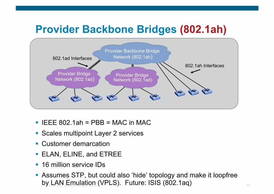
Provider Backbone Bridges (802.1ah)
IEEE 802.1ah = PBB = MAC in MAC Scales multipoint Layer 2 services Customer demarcation ELAN, ELINE, and ETREE 16 million service IDs Assumes STP, but could also ‘hide’ topology and make it loopfree
by LAN Emulation (VPLS). Future: ISIS (802.1aq)
802.1ad Interfaces 802.1ah Interfaces
Provider Bridge Network (802.1ad)
Provider Backbone Bridge Network (802.1ah)
Provider Bridge Network (802.1ad)
© 2007 Cisco Systems, Inc. All rights reserved. 47
Customer Network
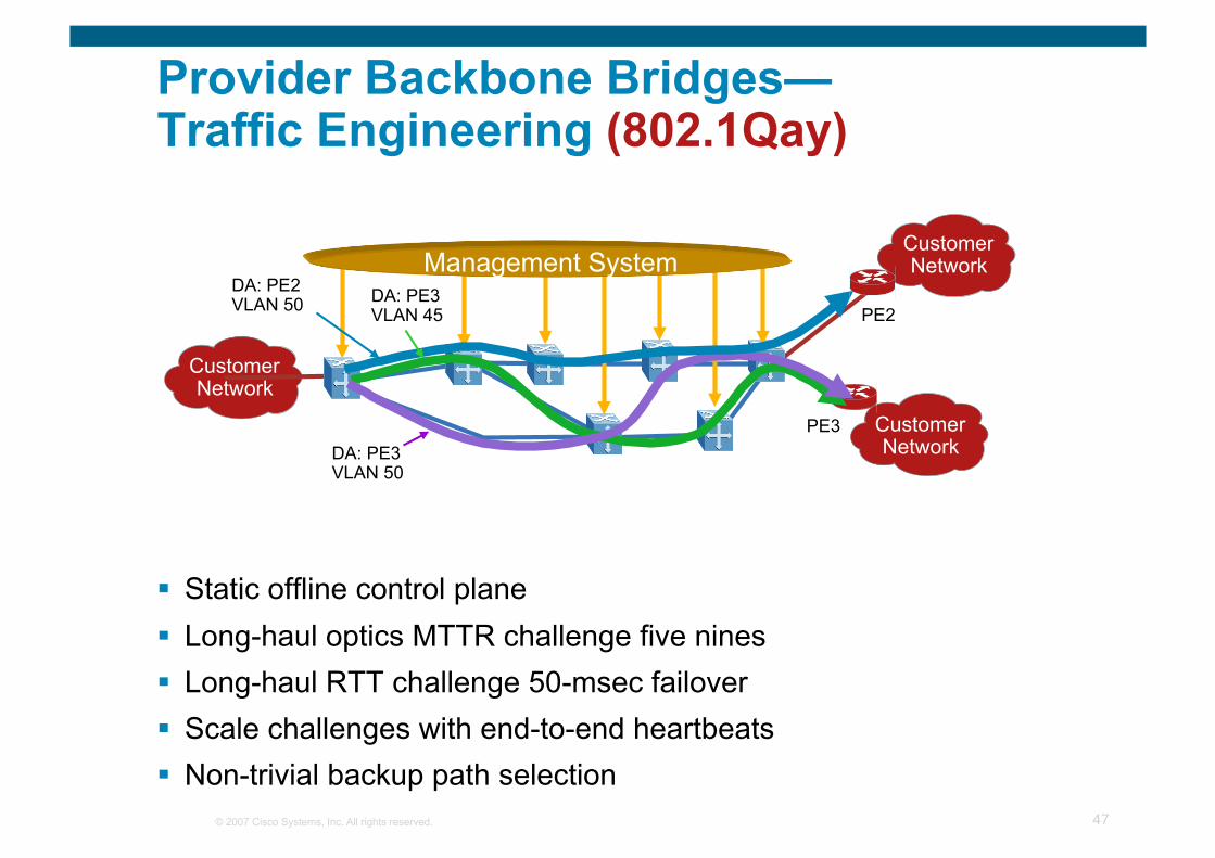
Provider Backbone Bridges— Traffic Engineering (802.1Qay)
Static offline control plane Long-haul optics MTTR challenge five nines Long-haul RTT challenge 50-msec failover Scale challenges with end-to-end heartbeats Non-trivial backup path selection
Customer Network
Customer Network
Management System DA: PE3 VLAN 45
DA: PE3 VLAN 50
PE3
PE2 DA: PE2 VLAN 50
© 2007 Cisco Systems, Inc. All rights reserved. 48
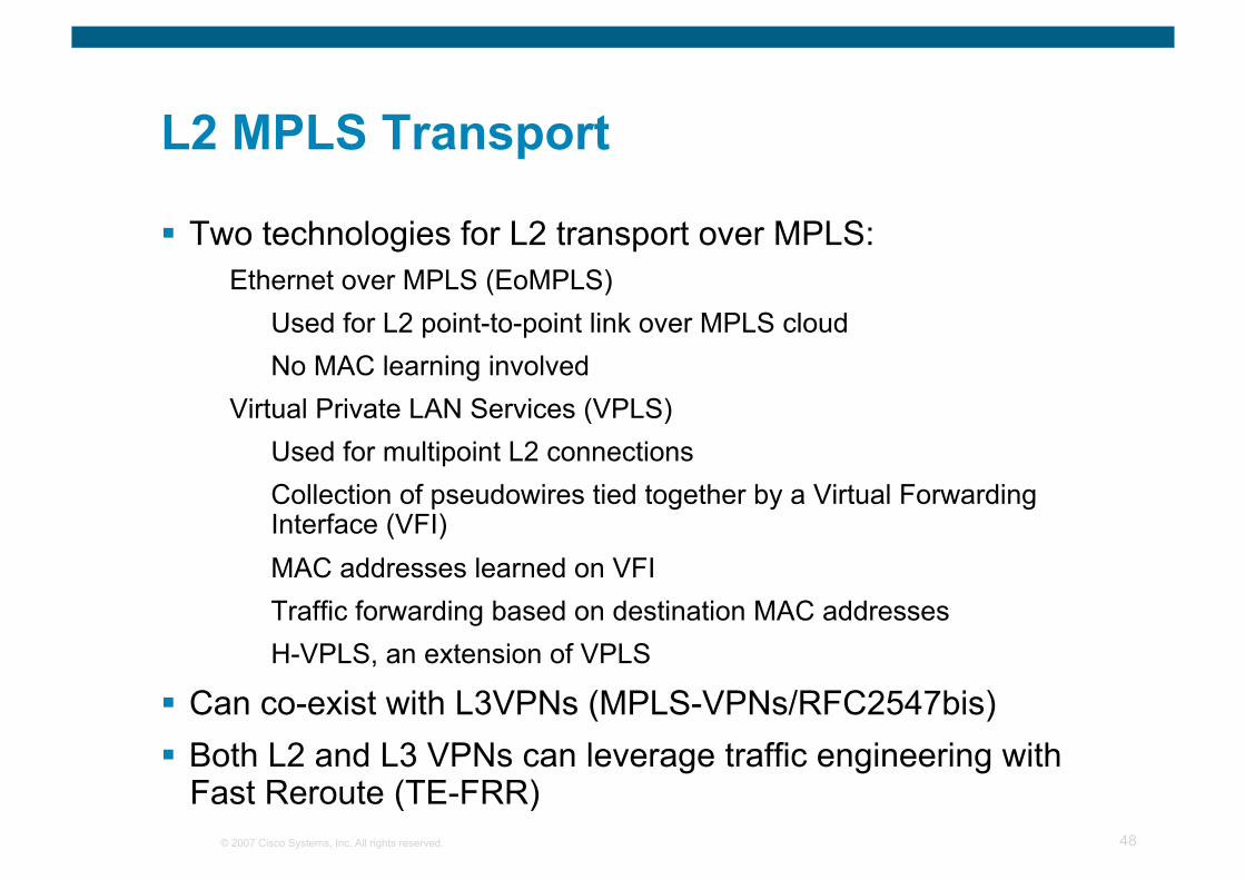
L2 MPLS Transport
Two technologies for L2 transport over MPLS: Ethernet over MPLS (EoMPLS)
Used for L2 point-to-point link over MPLS cloud No MAC learning involved
Virtual Private LAN Services (VPLS) Used for multipoint L2 connections Collection of pseudowires tied together by a Virtual Forwarding Interface (VFI) MAC addresses learned on VFI Traffic forwarding based on destination MAC addresses H-VPLS, an extension of VPLS
Can co-exist with L3VPNs (MPLS-VPNs/RFC2547bis) Both L2 and L3 VPNs can leverage traffic engineering with
Fast Reroute (TE-FRR)
© 2007 Cisco Systems, Inc. All rights reserved. 49
MPLS
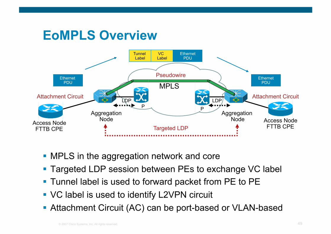
EoMPLS Overview
MPLS in the aggregation network and core Targeted LDP session between PEs to exchange VC label Tunnel label is used to forward packet from PE to PE VC label is used to identify L2VPN circuit Attachment Circuit (AC) can be port-based or VLAN-based
Pseudowire
Aggregation Node
P Aggregation
Node Access Node FTTB CPE
Access Node FTTB CPE
LDP LDP
Targeted LDP
Attachment Circuit Attachment Circuit
P
Tunnel Label
Ethernet PDU
VC Label
Ethernet PDU
Ethernet PDU
© 2007 Cisco Systems, Inc. All rights reserved. 50
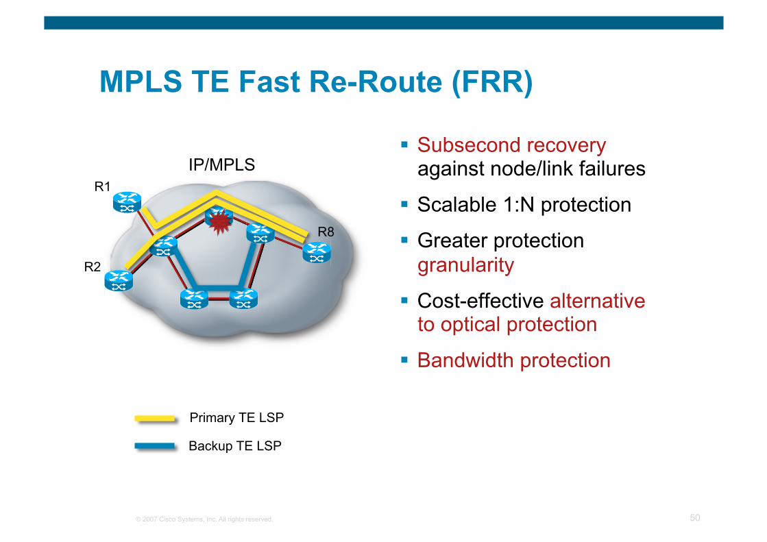
MPLS TE Fast Re-Route (FRR)
Subsecond recovery against node/link failures
Scalable 1:N protection
Greater protection granularity
Cost-effective alternative to optical protection
Bandwidth protection
Primary TE LSP
Backup TE LSP
IP/MPLS
R2
R1
R8
© 2007 Cisco Systems, Inc. All rights reserved. 51
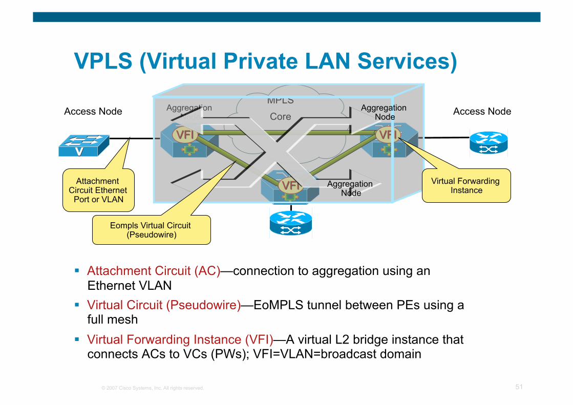
VPLS (Virtual Private LAN Services)
Attachment Circuit (AC)—connection to aggregation using an Ethernet VLAN
Virtual Circuit (Pseudowire)—EoMPLS tunnel between PEs using a full mesh
Virtual Forwarding Instance (VFI)—A virtual L2 bridge instance that connects ACs to VCs (PWs); VFI=VLAN=broadcast domain
Aggregation Node
MPLS
Core
Attachment Circuit Ethernet
Port or VLAN
Virtual Forwarding Instance
Eompls Virtual Circuit (Pseudowire)
Aggregation Node
Aggregation Node
Access Node Access Node
© 2007 Cisco Systems, Inc. All rights reserved. 52
U-PE B
Customer Equipment
CE
CE
CE
Ethernet UNI Ethernet UNI
N-PE 3
N-PE 4 N-PE 2
N-PE 1
PW
U-PE B
Customer Equipment
CE
CE
CE
Ethernet UNI Ethernet UNI
N-PE 3
N-PE 4 N-PE 2
N-PE 1
PW
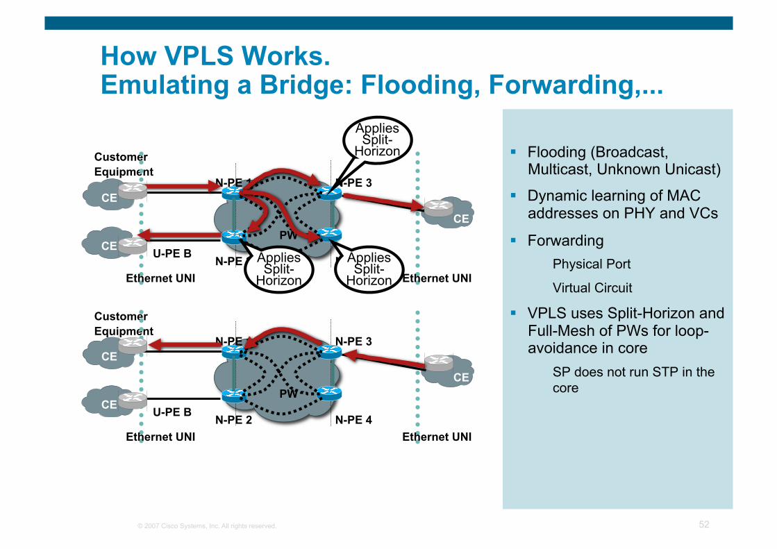
How VPLS Works. Emulating a Bridge: Flooding, Forwarding,...
Flooding (Broadcast, Multicast, Unknown Unicast)
Dynamic learning of MAC addresses on PHY and VCs
Forwarding Physical Port
Virtual Circuit
VPLS uses Split-Horizon and Full-Mesh of PWs for loop-avoidance in core
SP does not run STP in the core
Applies Split-
Horizon
Applies Split-
Horizon
Applies Split-
Horizon
© 2007 Cisco Systems, Inc. All rights reserved. 53
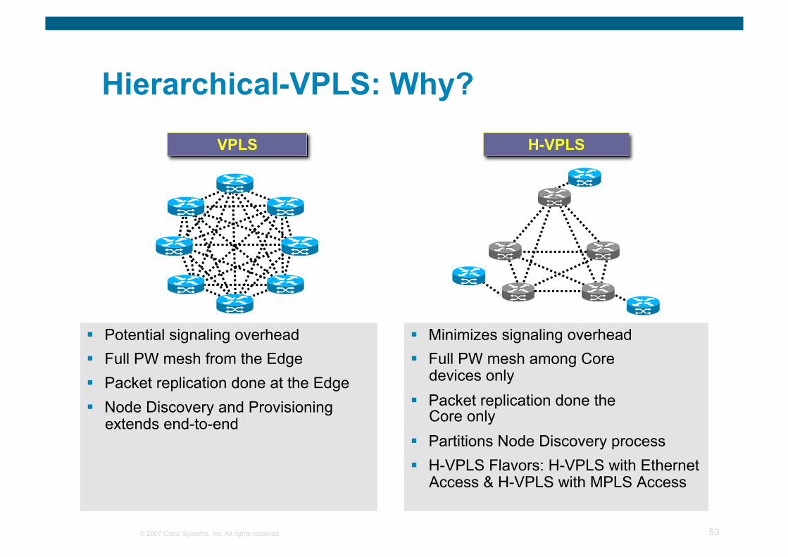
Hierarchical-VPLS: Why?
Potential signaling overhead Full PW mesh from the Edge Packet replication done at the Edge Node Discovery and Provisioning
extends end-to-end
Minimizes signaling overhead Full PW mesh among Core
devices only Packet replication done the
Core only Partitions Node Discovery process H-VPLS Flavors: H-VPLS with Ethernet
Access & H-VPLS with MPLS Access
VPLS H-VPLS
© 2007 Cisco Systems, Inc. All rights reserved. 54
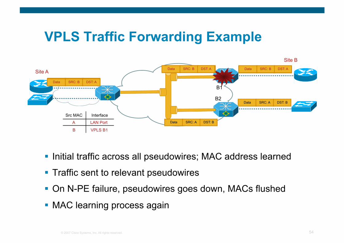
VPLS Traffic Forwarding Example
Initial traffic across all pseudowires; MAC address learned
Traffic sent to relevant pseudowires
On N-PE failure, pseudowires goes down, MACs flushed
MAC learning process again
Site B
Data SRC: A DST: B
Data SRC: A DST: B
B1
B2
Src MAC Interface
A LAN Port
B VPLS B1
Site A
Data SRC: A DST: B Data SRC: B DST: A
Data SRC: A DST: B Data SRC: B DST: A Data SRC: A DST: B Data SRC: B DST: A
© 2007 Cisco Systems, Inc. All rights reserved. 55
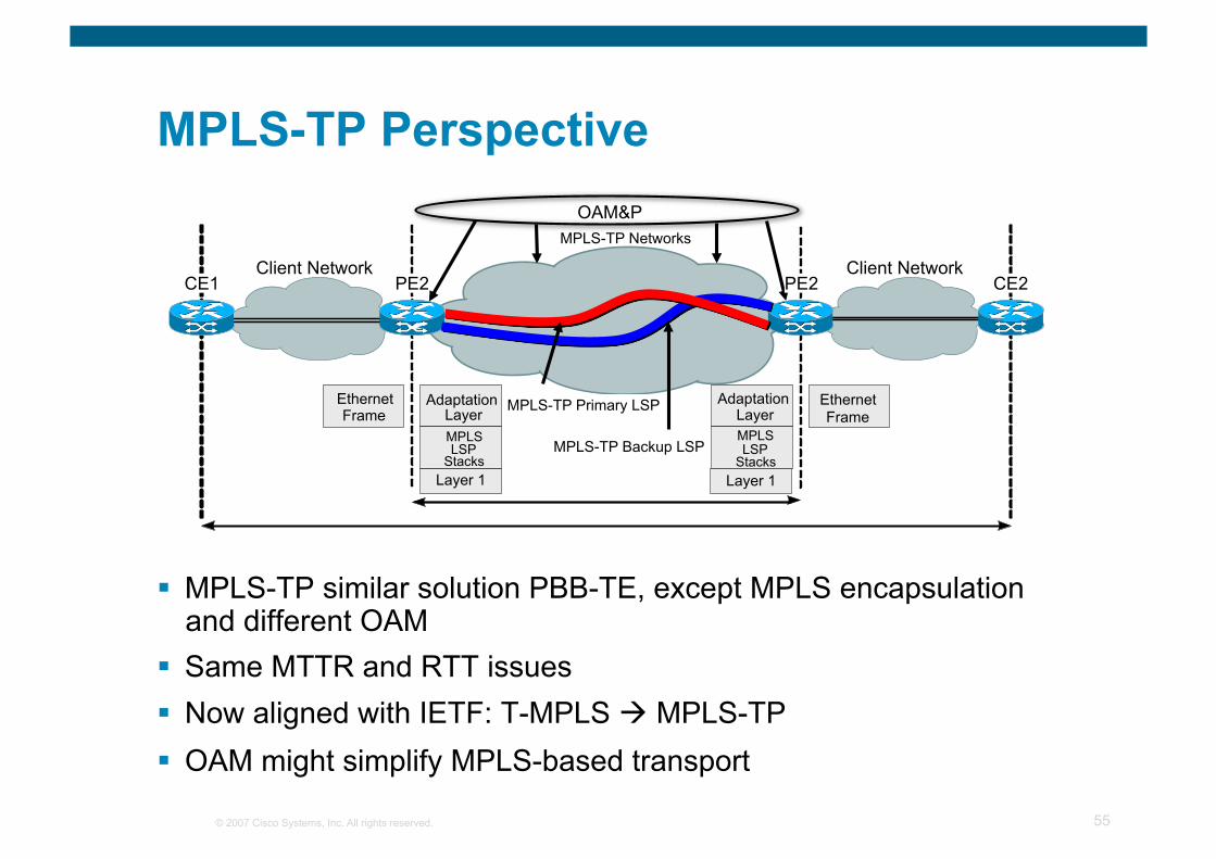
MPLS-TP Perspective
MPLS-TP similar solution PBB-TE, except MPLS encapsulation and different OAM
Same MTTR and RTT issues Now aligned with IETF: T-MPLS MPLS-TP OAM might simplify MPLS-based transport
MPLS-TP Networks
Client Network Client Network
Ethernet Frame
Adaptation Layer MPLS LSP
Stacks
Adaptation Layer MPLS LSP
Stacks
Ethernet Frame MPLS-TP Primary LSP
MPLS-TP Backup LSP
CE2
OAM&P
Layer 1 Layer 1
PE2 PE2 CE1
© 2007 Cisco Systems, Inc. All rights reserved. 56
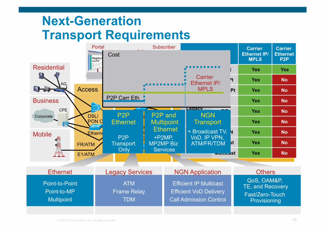
Next-Generation Transport Requirements
Policy Plane (per Subscriber)
Identity Address
Mgmt Subscriber Database Monitoring
Policy Definition Billing Presence Mediation
Single Tier
Hub and Spoke
or Ring
Aggregation L3 Service Edge L3 Core
Portal
Business
Residential
AG
Mobile
CPE DSL/ PON Cable
Ethernet
E1/ATM
Access
FR/ATM
Corporate
Ethernet
Point-to-Point Point-to-MP Multipoint
Legacy Services
ATM Frame Relay
TDM
NGN Application
Efficient IP Multicast Efficient VoD Delivery Call Admission Control
Others QoS, OAM&P,
TE, and Recovery Fast/Zero-Touch
Provisioning
Services Carrier
Ethernet IP/MPLS
Carrier Ethernet
P2P
Ethernet/ L2VPN/ Transport Services
Pt2Pt Yes Yes
Pt2MPt Yes No
MPt2MPt Yes No
Legacy Services
ATM Yes No
F/R Yes No
TDM Yes No
IP Services
L3VPN Yes No
Unicast Yes No
Multicast Yes No
P2P Ethernet
P2P and Multipoint Ethernet
P2P Transport
Only
+P2MP, MP2MP Biz
Services
NGN Transport
+ Broadcast TV, VoD, IP VPN, ATM/FR/TDM
Cost
Carrier Ethernet IP/
MPLS P2P Carr Eth
© 2007 Cisco Systems, Inc. All rights reserved. 57
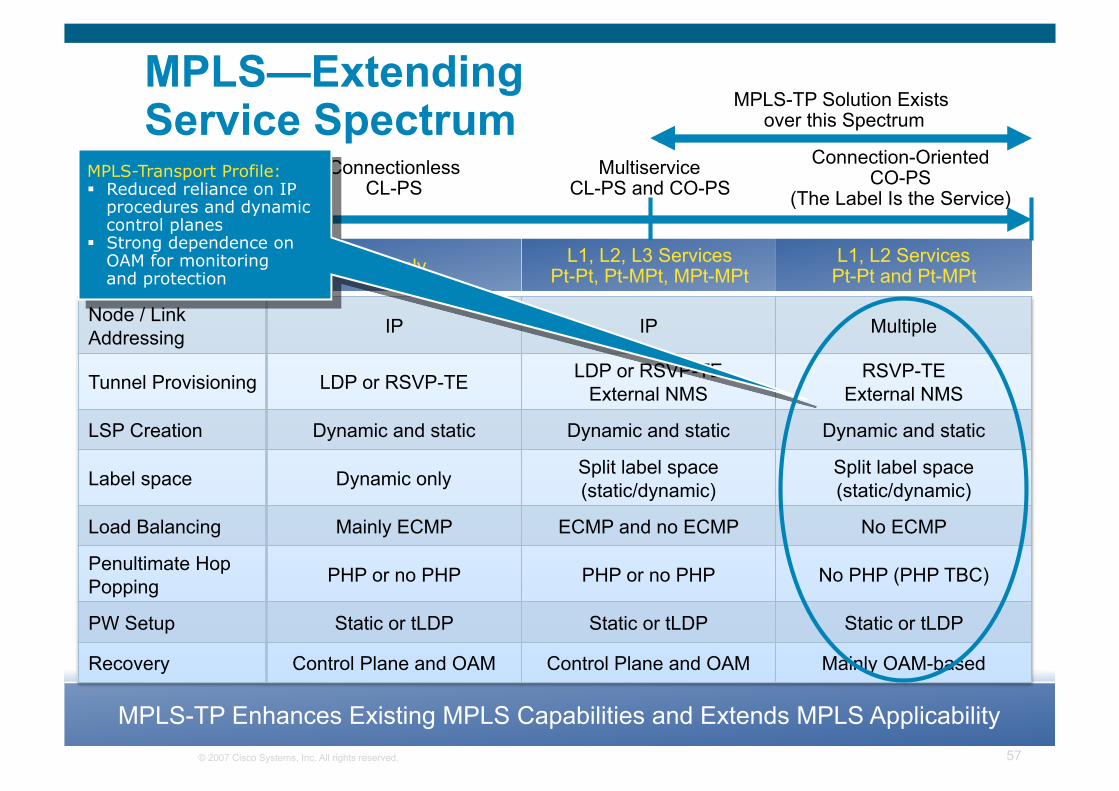
MPLS—Extending Service Spectrum
L3 Only L1, L2, L3 Services Pt-Pt, Pt-MPt, MPt-MPt
L1, L2 Services Pt-Pt and Pt-MPt
MPLS-TP Enhances Existing MPLS Capabilities and Extends MPLS Applicability
Node / Link Addressing IP IP Multiple
Tunnel Provisioning LDP or RSVP-TE LDP or RSVP-TE External NMS
RSVP-TE External NMS
LSP Creation Dynamic and static Dynamic and static Dynamic and static
Label space Dynamic only Split label space (static/dynamic)
Split label space (static/dynamic)
Load Balancing Mainly ECMP ECMP and no ECMP No ECMP
Penultimate Hop Popping PHP or no PHP PHP or no PHP No PHP (PHP TBC)
PW Setup Static or tLDP Static or tLDP Static or tLDP
Recovery Control Plane and OAM Control Plane and OAM Mainly OAM-based
Connectionless CL-PS
Multiservice CL-PS and CO-PS
Connection-Oriented CO-PS
(The Label Is the Service)
MPLS-TP Solution Exists over this Spectrum
MPLS-Transport Profile: Reduced reliance on IP
procedures and dynamic control planes
Strong dependence on OAM for monitoring and protection
© 2007 Cisco Systems, Inc. All rights reserved. 58
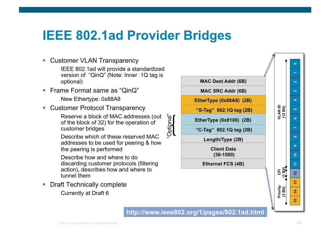
IEEE 802.1ad Provider Bridges
Customer VLAN Transparency IEEE 802.1ad will provide a standardized version of “QinQ” (Note: Inner .1Q tag is optional)
Frame Format same as “QinQ” New Ethertype: 0x88A8
Customer Protocol Transparency Reserve a block of MAC addresses (out of the block of 32) for the operation of customer bridges Describe which of these reserved MAC addresses to be used for peering & how the peering is performed Describe how and where to do discarding customer protocols (filtering action), describes how and where to tunnel them
Draft Technically complete Currently at Draft 6
N-PE 4
Ethernet UNI
PW
Length/Type (2B)
Client Data (38-1500)
Ethernet FCS (4B)
MAC Dest Addr (6B)
MAC SRC Addr (6B)
EtherType (0x88A8) (2B)
“S-Tag” 802.1Q tag (2B)
EtherType (0x8100) (2B)
“C-Tag” 802.1Q tag (2B)
15
14
13
12
11
10
9 8
7 6
5 4
3 2
1 0
VLA
N ID
(1
2 B
it)
CFI
(1
Bit)
Pr
iorit
y (3
Bit)
“Opt
iona
l”
http://www.ieee802.org/1/pages/802.1ad.html
© 2007 Cisco Systems, Inc. All rights reserved. 59
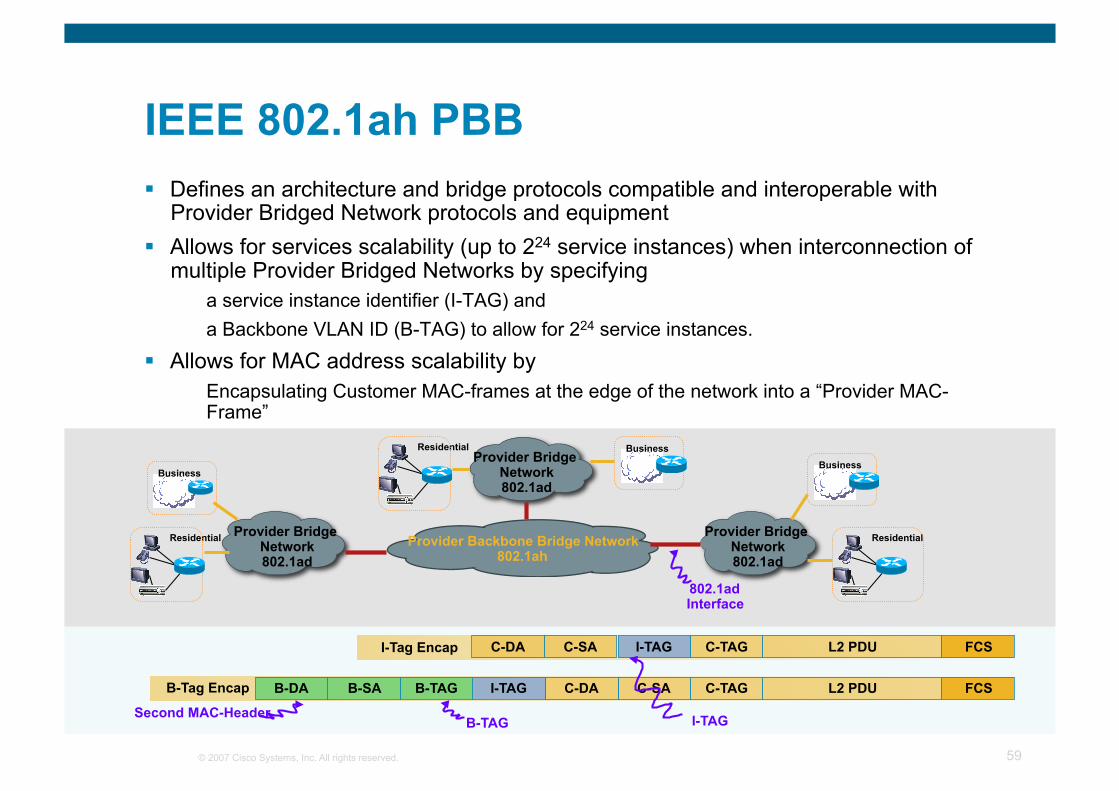
IEEE 802.1ah PBB Defines an architecture and bridge protocols compatible and interoperable with
Provider Bridged Network protocols and equipment Allows for services scalability (up to 224 service instances) when interconnection of
multiple Provider Bridged Networks by specifying a service instance identifier (I-TAG) and a Backbone VLAN ID (B-TAG) to allow for 224 service instances.
Allows for MAC address scalability by Encapsulating Customer MAC-frames at the edge of the network into a “Provider MAC-Frame”
FCS L2 PDU C-TAG C-SA C-DA I-TAG B-TAG B-SA B-DA
FCS L2 PDU C-TAG C-SA C-DA I-TAG I-Tag Encap
B-Tag Encap
B-TAG Second MAC-Header
Business
Residential
Business
Residential
Business Residential
Provider Backbone Bridge Network 802.1ah
Provider Bridge Network 802.1ad
Provider Bridge Network 802.1ad
Provider Bridge Network 802.1ad
802.1ad Interface
I-TAG
© 2007 Cisco Systems, Inc. All rights reserved. 60
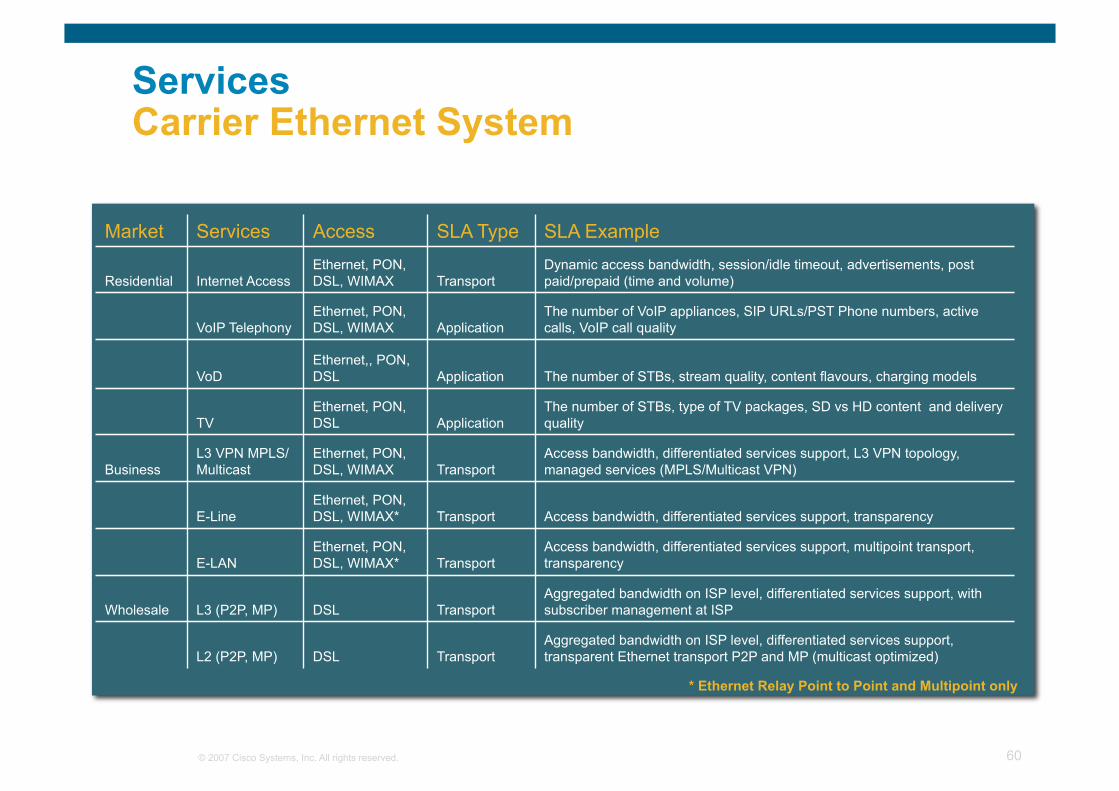
Services Carrier Ethernet System
Market Services Access SLA Type SLA Example Residential Internet Access Ethernet, PON,
DSL, WIMAX Transport Dynamic access bandwidth, session/idle timeout, advertisements, post paid/prepaid (time and volume)
VoIP Telephony Ethernet, PON, DSL, WIMAX Application The number of VoIP appliances, SIP URLs/PST Phone numbers, active
calls, VoIP call quality VoD Ethernet,, PON,
DSL Application The number of STBs, stream quality, content flavours, charging models TV Ethernet, PON,
DSL Application The number of STBs, type of TV packages, SD vs HD content and delivery quality
Business L3 VPN MPLS/Multicast Ethernet, PON,
DSL, WIMAX Transport Access bandwidth, differentiated services support, L3 VPN topology, managed services (MPLS/Multicast VPN)
E-Line Ethernet, PON, DSL, WIMAX* Transport Access bandwidth, differentiated services support, transparency
E-LAN Ethernet, PON, DSL, WIMAX* Transport Access bandwidth, differentiated services support, multipoint transport,
transparency Wholesale L3 (P2P, MP) DSL Transport Aggregated bandwidth on ISP level, differentiated services support, with
subscriber management at ISP L2 (P2P, MP) DSL Transport Aggregated bandwidth on ISP level, differentiated services support,
transparent Ethernet transport P2P and MP (multicast optimized) * Ethernet Relay Point to Point and Multipoint only
© 2007 Cisco Systems, Inc. All rights reserved. 61
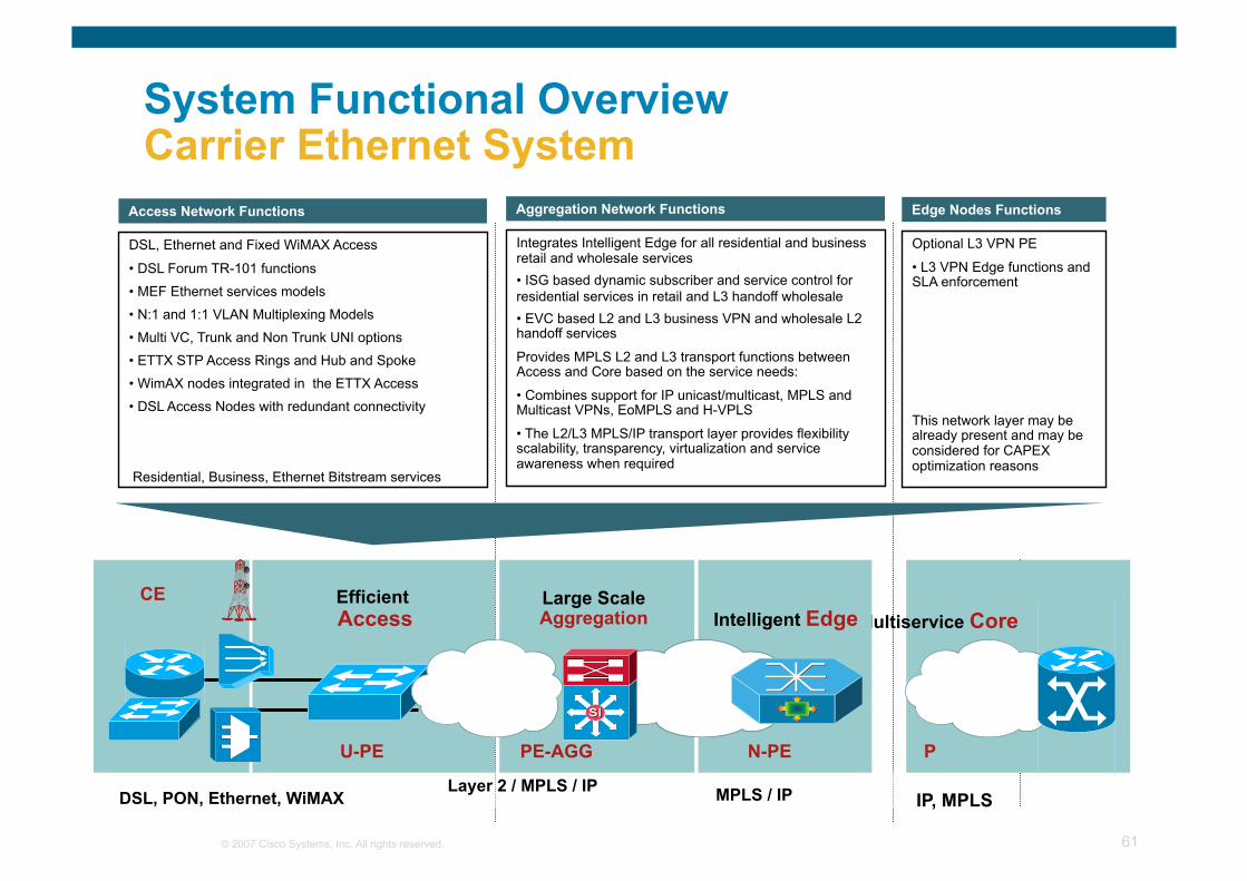
System Functional Overview Carrier Ethernet System
DSL, Ethernet and Fixed WiMAX Access
• DSL Forum TR-101 functions
• MEF Ethernet services models
• N:1 and 1:1 VLAN Multiplexing Models
• Multi VC, Trunk and Non Trunk UNI options
• ETTX STP Access Rings and Hub and Spoke
• WimAX nodes integrated in the ETTX Access
• DSL Access Nodes with redundant connectivity
Residential, Business, Ethernet Bitstream services
Access Network Functions
Integrates Intelligent Edge for all residential and business retail and wholesale services • ISG based dynamic subscriber and service control for residential services in retail and L3 handoff wholesale • EVC based L2 and L3 business VPN and wholesale L2 handoff services
Provides MPLS L2 and L3 transport functions between Access and Core based on the service needs:
• Combines support for IP unicast/multicast, MPLS and Multicast VPNs, EoMPLS and H-VPLS
• The L2/L3 MPLS/IP transport layer provides flexibility scalability, transparency, virtualization and service awareness when required
Aggregation Network Functions
Optional L3 VPN PE
• L3 VPN Edge functions and SLA enforcement
This network layer may be already present and may be considered for CAPEX optimization reasons
Edge Nodes Functions
DSL, PON, Ethernet, WiMAX IP, MPLS
Full Service Customer Equipment
Multiservice Core Efficient Access
U-PE
MPLS / IP
Large Scale Aggregation Intelligent Edge
PE-AGG N-PE P
CE
Layer 2 / MPLS / IP
© 2007 Cisco Systems, Inc. All rights reserved. 62
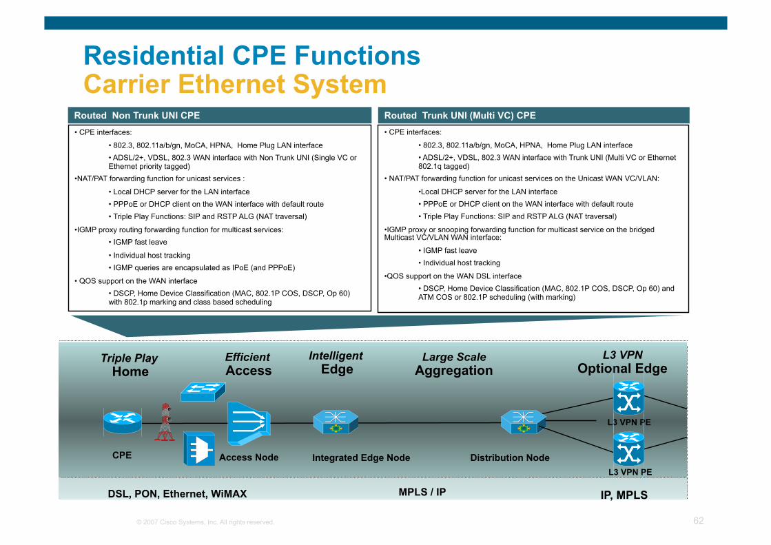
Residential CPE Functions Carrier Ethernet System
• CPE interfaces:
• 802.3, 802.11a/b/gn, MoCA, HPNA, Home Plug LAN interface • ADSL/2+, VDSL, 802.3 WAN interface with Non Trunk UNI (Single VC or Ethernet priority tagged)
• NAT/PAT forwarding function for unicast services :
• Local DHCP server for the LAN interface • PPPoE or DHCP client on the WAN interface with default route • Triple Play Functions: SIP and RSTP ALG (NAT traversal)
• IGMP proxy routing forwarding function for multicast services: • IGMP fast leave
• Individual host tracking • IGMP queries are encapsulated as IPoE (and PPPoE)
• QOS support on the WAN interface • DSCP, Home Device Classification (MAC, 802.1P COS, DSCP, Op 60) with 802.1p marking and class based scheduling
Routed Non Trunk UNI CPE • CPE interfaces:
• 802.3, 802.11a/b/gn, MoCA, HPNA, Home Plug LAN interface • ADSL/2+, VDSL, 802.3 WAN interface with Trunk UNI (Multi VC or Ethernet 802.1q tagged)
• NAT/PAT forwarding function for unicast services on the Unicast WAN VC/VLAN:
• Local DHCP server for the LAN interface • PPPoE or DHCP client on the WAN interface with default route • Triple Play Functions: SIP and RSTP ALG (NAT traversal)
• IGMP proxy or snooping forwarding function for multicast service on the bridged Multicast VC/VLAN WAN interface:
• IGMP fast leave • Individual host tracking
• QOS support on the WAN DSL interface • DSCP, Home Device Classification (MAC, 802.1P COS, DSCP, Op 60) and ATM COS or 802.1P scheduling (with marking)
Routed Trunk UNI (Multi VC) CPE
Efficient Access
Integrated Edge Node
MPLS / IP
Access Node Distribution Node CPE
Triple Play Home
L3 VPN Optional Edge
L3 VPN PE
IP, MPLS
L3 VPN PE
Large Scale Aggregation
Intelligent Edge
DSL, PON, Ethernet, WiMAX
© 2007 Cisco Systems, Inc. All rights reserved. 63
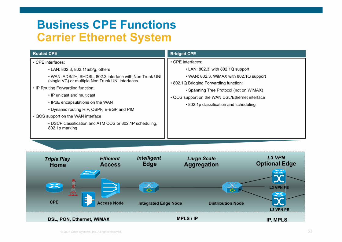
Business CPE Functions Carrier Ethernet System
• CPE interfaces:
• LAN: 802.3, 802.11a/b/g, others
• WAN: ADS/2+, SHDSL, 802.3 interface with Non Trunk UNI (single VC) or multiple Non Trunk UNI interfaces
• IP Routing Forwarding function:
• IP unicast and multicast
• IPoE encapsulations on the WAN
• Dynamic routing RIP, OSPF, E-BGP and PIM • QOS support on the WAN interface
• DSCP classification and ATM COS or 802.1P scheduling, 802.1p marking
Routed CPE
• CPE interfaces:
• LAN: 802.3, with 802.1Q support
• WAN: 802.3, WiMAX with 802.1Q support • 802.1Q Bridging Forwarding function:
• Spanning Tree Protocol (not on WiMAX)
• QOS support on the WAN DSL/Ethernet interface
• 802.1p classification and scheduling
Bridged CPE
Efficient Access
Integrated Edge Node
MPLS / IP
Access Node Distribution Node CPE
Triple Play Home
L3 VPN Optional Edge
L3 VPN PE
IP, MPLS
L3 VPN PE
Large Scale Aggregation
Intelligent Edge
DSL, PON, Ethernet, WiMAX
© 2007 Cisco Systems, Inc. All rights reserved. 64
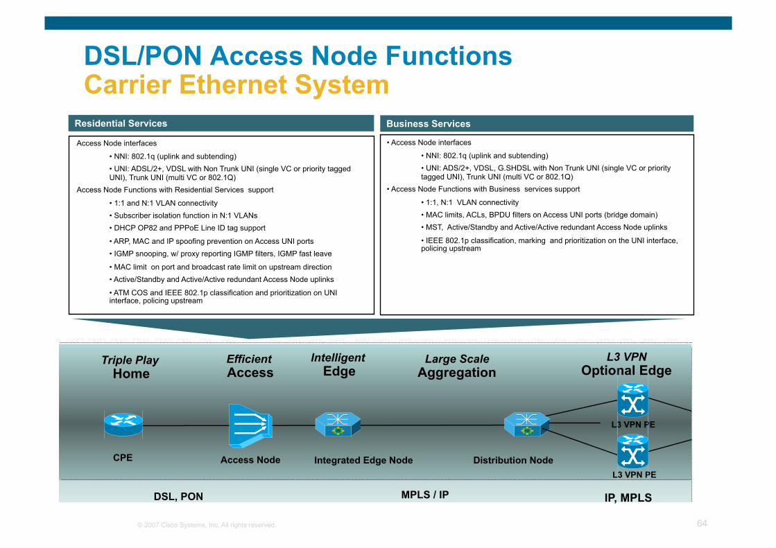
DSL/PON Access Node Functions Carrier Ethernet System
Access Node interfaces
• NNI: 802.1q (uplink and subtending) • UNI: ADSL/2+, VDSL with Non Trunk UNI (single VC or priority tagged UNI), Trunk UNI (multi VC or 802.1Q)
Access Node Functions with Residential Services support
• 1:1 and N:1 VLAN connectivity • Subscriber isolation function in N:1 VLANs • DHCP OP82 and PPPoE Line ID tag support
• ARP, MAC and IP spoofing prevention on Access UNI ports • IGMP snooping, w/ proxy reporting IGMP filters, IGMP fast leave
• MAC limit on port and broadcast rate limit on upstream direction • Active/Standby and Active/Active redundant Access Node uplinks
• ATM COS and IEEE 802.1p classification and prioritization on UNI interface, policing upstream
Residential Services
• Access Node interfaces
• NNI: 802.1q (uplink and subtending) • UNI: ADS/2+, VDSL, G.SHDSL with Non Trunk UNI (single VC or priority tagged UNI), Trunk UNI (multi VC or 802.1Q)
• Access Node Functions with Business services support
• 1:1, N:1 VLAN connectivity • MAC limits, ACLs, BPDU filters on Access UNI ports (bridge domain) • MST, Active/Standby and Active/Active redundant Access Node uplinks
• IEEE 802.1p classification, marking and prioritization on the UNI interface, policing upstream
Business Services
Efficient Access
Integrated Edge Node
MPLS / IP
Access Node Distribution Node CPE
Triple Play Home
L3 VPN Optional Edge
L3 VPN PE
IP, MPLS
L3 VPN PE
Large Scale Aggregation
Intelligent Edge
DSL, PON
© 2007 Cisco Systems, Inc. All rights reserved. 65
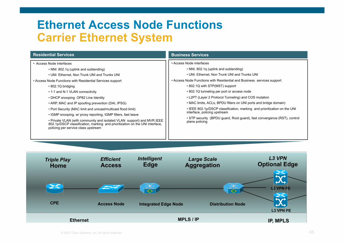
Ethernet Access Node Functions Carrier Ethernet System
• Access Node interfaces
• NNI: 802.1q (uplink and subtending) • UNI: Ethernet, Non Trunk UNI and Trunks UNI
• Access Node Functions with Residential Services support • 802.1Q bridging • 1:1 and N:1 VLAN connectivity
• DHCP snooping OP82 Line Identity • ARP, MAC and IP spoofing prevention (DAI, IPSG)
• Port Security (MAC limit and unicast/multicast flood limit) • IGMP snooping, w/ proxy reporting, IGMP filters, fast leave
• Private VLAN (with community and isolated VLAN support) and MVR IEEE 802.1p/DSCP classification, marking and prioritization on the UNI interface, policing per service class upstream
Residential Services
• Access Node interfaces
• NNI: 802.1q (uplink and subtending) • UNI: Ethernet, Non Trunk UNI and Trunks UNI
• Access Node Functions with Residential and Business services support • 802.1Q with STP(MST) support • 802.1Q tunneling per port or access node
• L2PT (Layer 2 Protocol Tunneling) and COS mutation • MAC limits, ACLs, BPDU filters on UNI ports and bridge domain)
• IEEE 802.1p/DSCP classification, marking and prioritization on the UNI interface, policing upstream
• STP security (BPDU guard, Root guard), fast convergence (RST), control plane policing
Business Services
Efficient Access
Integrated Edge Node
MPLS / IP
Access Node Distribution Node CPE
Triple Play Home
L3 VPN Optional Edge
L3 VPN PE
IP, MPLS
L3 VPN PE
Large Scale Aggregation
Intelligent Edge
Ethernet
© 2007 Cisco Systems, Inc. All rights reserved. 66
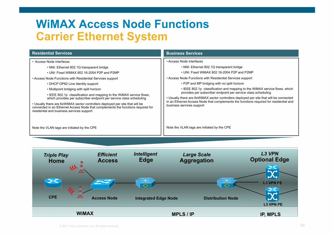
WiMAX Access Node Functions Carrier Ethernet System
Efficient Access
Integrated Edge Node
MPLS / IP WiMAX
Access Node Distribution Node CPE
Triple Play Home
• Access Node interfaces
• NNI: Ethernet 802.1Q transparent bridge • UNI: Fixed WiMAX 802.16-2004 P2P and P2MP
• Access Node Functions with Residential Services support • DHCP OP82 Line Identity support • Multipoint bridging with split horizon
• IEEE 802.1p classification and mapping to the WiMAX service flows, which provides per subscriber endpoint per service class scheduling
• Usually there are 6xWiMAX sector controllers deployed per site that will be connected in an Ethernet Access Node that complements the functions required for residential and business services support
Note the VLAN tags are initiated by the CPE
Residential Services
• Access Node interfaces
• NNI: Ethernet 802.1Q transparent bridge • UNI: Fixed WiMAX 802.16-2004 P2P and P2MP
• Access Node Functions with Residential Services support • P2P and MP bridging with no split horizon • IEEE 802.1p classification and mapping to the WiMAX service flows, which provides per subscriber endpoint per service class scheduling
• Usually there are 6xWiMAX sector controllers deployed per site that will be connected in an Ethernet Access Node that complements the functions required for residential and business services support
Note the VLAN tags are initiated by the CPE
Business Services
L3 VPN Optional Edge
L3 VPN PE
IP, MPLS
L3 VPN PE
Large Scale Aggregation
Intelligent Edge
© 2007 Cisco Systems, Inc. All rights reserved. 67
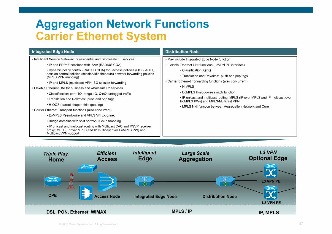
Aggregation Network Functions Carrier Ethernet System
• Intelligent Service Gateway for residential and wholesale L3 services
• IP and PPPoE sessions with AAA (RADIUS COA) • Dynamic policy control (RADIUS COA) for: access policies (QOS, ACLs), session control policies (session/idle timeouts) network forwarding policies (MPLS VPN mapping)
• IP and MPLS (multicast) VPN ISG session forwarding • Flexible Ethernet UNI for business and wholesale L2 services
• Classification: port, 1Q, range 1Q, QinQ, untagged traffic • Translation and Rewrites: push and pop tags
• H-QOS (parent shaper child queuing) • Carrier Ethernet Transport functions (also concurrent):
• EoMPLS Pseudowire and VPLS VFI x-connect
• Bridge domains with split horizon, IGMP snooping • IP unicast and multicast routing with Multicast CAC and RSVP receiver proxy; MPLS(IP over MPLS and IP multicast over EoMPLS PW) and Multicast VPN support
Integrated Edge Node
• May include Integrated Edge Node function
• Flexible Ethernet UNI functions (L3VPN PE interface): • Classification: QinQ
• Translation and Rewrites: push and pop tags • Carrier Ethernet Forwarding functions (also concurrent):
• H-VPLS
• EoMPLS Pseudowire switch function • IP unicast and multicast routing; MPLS (IP over MPLS and IP multicast over EoMPLS PWs) and MPLS/Multicast VPN • MPLS NNI function between Aggregation Network and Core
Distribution Node
Efficient Access
Integrated Edge Node
MPLS / IP
Access Node Distribution Node CPE
Triple Play Home
L3 VPN Optional Edge
L3 VPN PE
IP, MPLS
L3 VPN PE
Large Scale Aggregation
Intelligent Edge
DSL, PON, Ethernet, WiMAX
© 2007 Cisco Systems, Inc. All rights reserved. 68
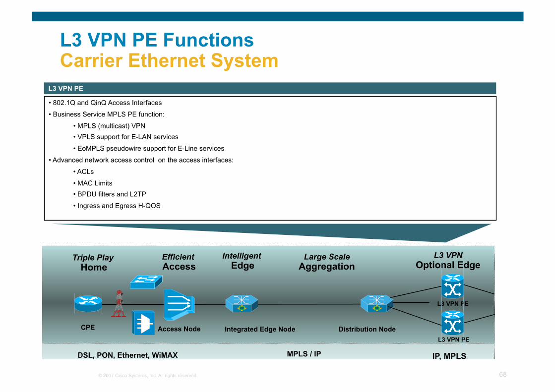
L3 VPN PE Functions Carrier Ethernet System
• 802.1Q and QinQ Access Interfaces
• Business Service MPLS PE function:
• MPLS (multicast) VPN • VPLS support for E-LAN services
• EoMPLS pseudowire support for E-Line services
• Advanced network access control on the access interfaces:
• ACLs
• MAC Limits • BPDU filters and L2TP
• Ingress and Egress H-QOS
L3 VPN PE
Efficient Access
Integrated Edge Node
MPLS / IP
Access Node Distribution Node CPE
Triple Play Home
L3 VPN Optional Edge
L3 VPN PE
IP, MPLS
L3 VPN PE
Large Scale Aggregation
Intelligent Edge
DSL, PON, Ethernet, WiMAX
© 2007 Cisco Systems, Inc. All rights reserved. 69
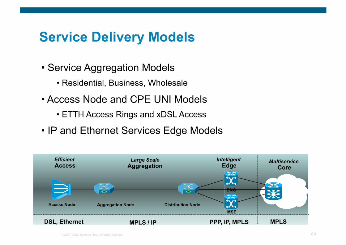
• Service Aggregation Models • Residential, Business, Wholesale
• Access Node and CPE UNI Models • ETTH Access Rings and xDSL Access
• IP and Ethernet Services Edge Models
Service Delivery Models
Large Scale Aggregation
Intelligent Edge
Multiservice Core
Efficient Access
Aggregation Node MSE
PPP, IP, MPLS MPLS MPLS / IP DSL, Ethernet
Access Node
BNG
Distribution Node
© 2007 Cisco Systems, Inc. All rights reserved. 70
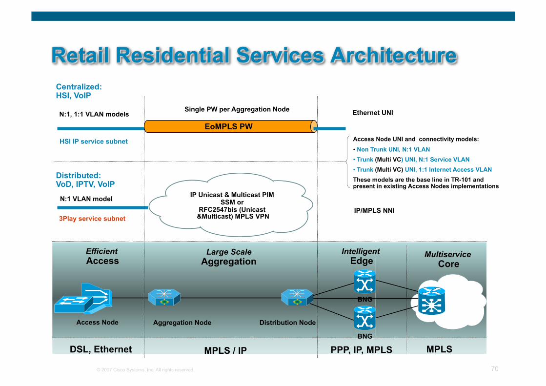
Large Scale Aggregation
Intelligent Edge
Multiservice Core
Efficient Access
Aggregation Node
BNG
PPP, IP, MPLS MPLS MPLS / IP DSL, Ethernet
Distributed: VoD, IPTV, VoIP
N:1, 1:1 VLAN models
EoMPLS Pseudowire
Centralized: HSI, VoIP
Access Node
N:1 VLAN model
BNG
Distribution Node
IP Unicast & Multicast PIM SSM or
RFC2547bis (Unicast &Multicast) MPLS VPN
EoMPLS PW
HSI IP service subnet
3Play service subnet
Single PW per Aggregation Node
Access Node UNI and connectivity models: • Non Trunk UNI, N:1 VLAN • Trunk (Multi VC) UNI, N:1 Service VLAN • Trunk (Multi VC) UNI, 1:1 Internet Access VLAN These models are the base line in TR-101 and present in existing Access Nodes implementations
IP/MPLS NNI
Ethernet UNI
© 2007 Cisco Systems, Inc. All rights reserved. 71
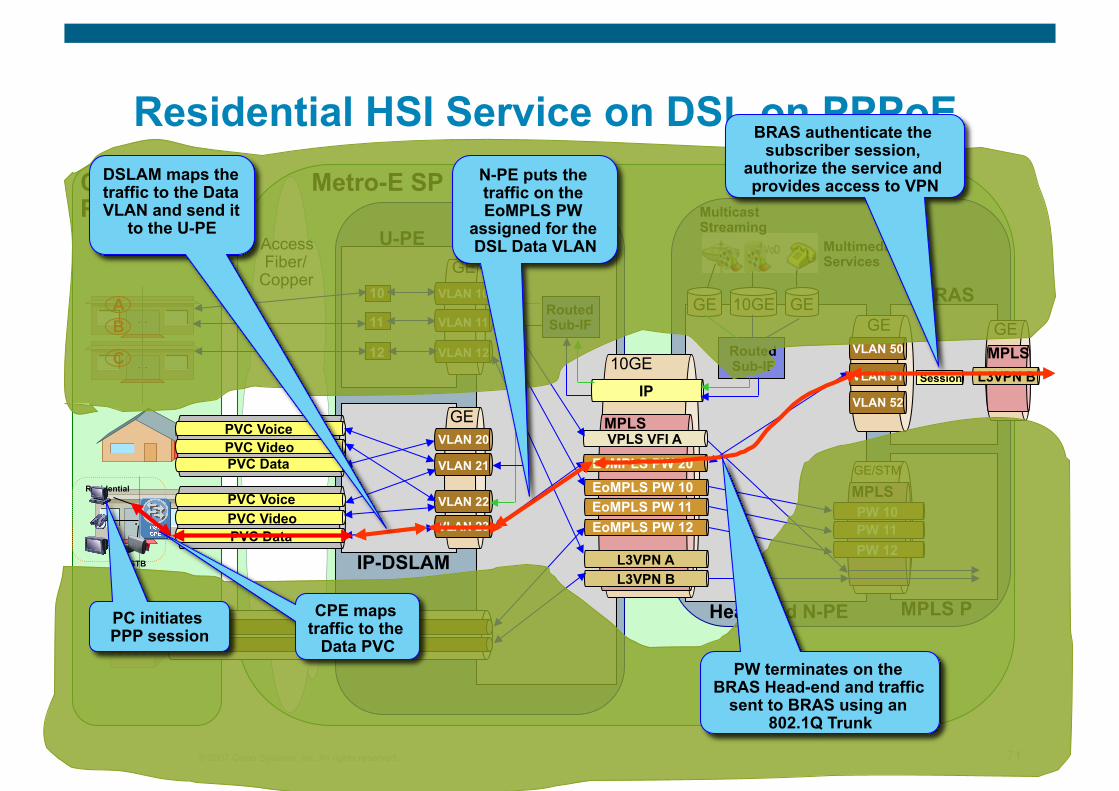
Residential HSI Service on DSL on PPPoE Customer Premises
Metro-E SP Backbone
Access Fiber/
Copper
10GE
GE
GE
GE GE 10GE
N-PE
Head-end N-PE MPLS P
U-PE
IP-DSLAM
BRAS
Multimedia Services
Multicast Streaming
VLAN 200 VLAN 201
IP
MPLS
MPLS GE/STM
GE Routed Sub-IF
Routed Sub-IF
VLAN 10
VLAN 11
VLAN 12
VLAN 20
VLAN 21
VLAN 22
VLAN 23
EoMPLS PW 10 EoMPLS PW 11 EoMPLS PW 12
L3VPN A L3VPN B
VPLS VFI A
PW 10 PW 11
E
10
11
12
PW 12
PVC Voice PVC Video PVC Data
PVC Voice PVC Video PVC Data
EoMPLS PW 20
VLAN 50
VLAN 51
VLAN 52
Session L3VPN B MPLS GE B
A
F
C
Residential
STB
PC initiates PPP session
DSLAM maps the traffic to the Data VLAN and send it
to the U-PE
N-PE puts the traffic on the EoMPLS PW
assigned for the DSL Data VLAN
CPE maps traffic to the
Data PVC PW terminates on the
BRAS Head-end and traffic sent to BRAS using an
802.1Q Trunk
BRAS authenticate the subscriber session,
authorize the service and provides access to VPN
© 2007 Cisco Systems, Inc. All rights reserved. 72
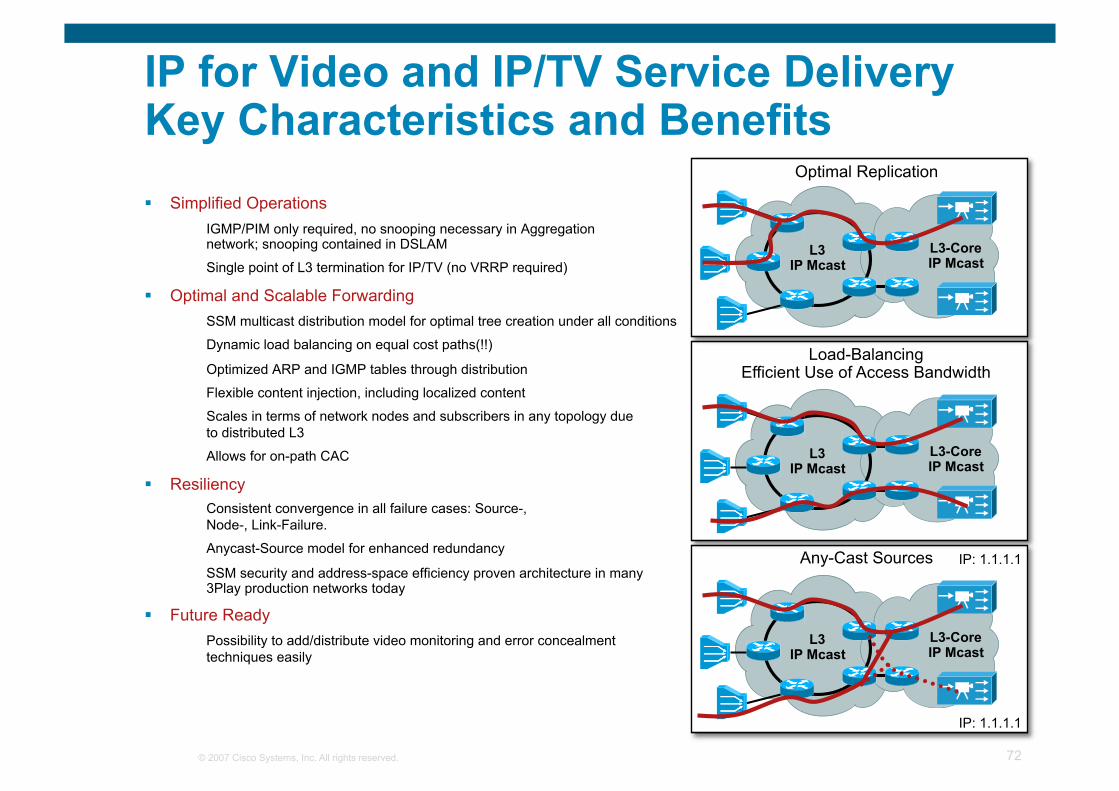
L3 IP Mcast
L3-Core IP Mcast
L3 IP Mcast
L3-Core IP Mcast
L3 IP Mcast
L3-Core IP Mcast
IP for Video and IP/TV Service Delivery Key Characteristics and Benefits Simplified Operations
IGMP/PIM only required, no snooping necessary in Aggregation network; snooping contained in DSLAM
Single point of L3 termination for IP/TV (no VRRP required)
Optimal and Scalable Forwarding SSM multicast distribution model for optimal tree creation under all conditions
Dynamic load balancing on equal cost paths(!!)
Optimized ARP and IGMP tables through distribution
Flexible content injection, including localized content
Scales in terms of network nodes and subscribers in any topology due to distributed L3
Allows for on-path CAC
Resiliency Consistent convergence in all failure cases: Source-, Node-, Link-Failure.
Anycast-Source model for enhanced redundancy
SSM security and address-space efficiency proven architecture in many 3Play production networks today
Future Ready Possibility to add/distribute video monitoring and error concealment techniques easily
IP: 1.1.1.1
IP: 1.1.1.1
Optimal Replication
Load-Balancing Efficient Use of Access Bandwidth
Any-Cast Sources
© 2007 Cisco Systems, Inc. All rights reserved. 73
IP Multicast
L3 VHO
L3 VSO L3 VSO
L3 VSO L3 VSO
1
2 3
4
L3 VHO
AnyCast
PIM SSM Fast IGP
Optimum Replication and Load-Balancing
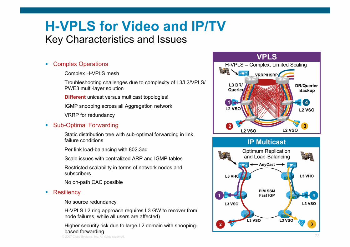
H-VPLS for Video and IP/TV Key Characteristics and Issues
Complex Operations Complex H-VPLS mesh
Troubleshooting challenges due to complexity of L3/L2/VPLS/PWE3 multi-layer solution
Different unicast versus multicast topologies!
IGMP snooping across all Aggregation network
VRRP for redundancy
Sub-Optimal Forwarding Static distribution tree with sub-optimal forwarding in link failure conditions
Per link load-balancing with 802.3ad
Scale issues with centralized ARP and IGMP tables
Restricted scalability in terms of network nodes and subscribers
No on-path CAC possible
Resiliency No source redundancy
H-VPLS L2 ring approach requires L3 GW to recover from node failures, while all users are affected)
Higher security risk due to large L2 domain with snooping- based forwarding
VPLS
L3 DR/ Querier
L2 VSO
L2 VSO
L2 VSO
1
2 3
4
DR/Querier Backup
VRRP/HSRP
L2 VSO
H-VPLS = Complex, Limited Scaling
© 2007 Cisco Systems, Inc. All rights reserved. 74
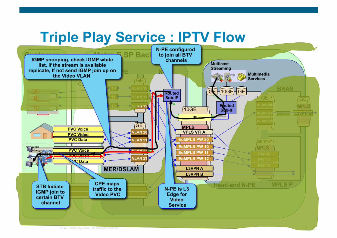
Triple Play Service : IPTV Flow Customer Premises
Metro-E SP Backbone
Access Fiber/
Copper
10GE
GE
GE
GE GE 10GE
N-PE
Head-end N-PE MPLS P
U-PE
MER/DSLAM
BRAS
Multimedia Services
Multicast Streaming
VLAN 200 VLAN 201
IP
MPLS
MPLS GE/STM
GE Routed Sub-IF
Routed Sub-IF
VLAN 10
VLAN 11
VLAN 12
VLAN 20
VLAN 21
VLAN 22
VLAN 23
EoMPLS PW 10 EoMPLS PW 11 EoMPLS PW 12
L3VPN A L3VPN B
VPLS VFI A
PW 10 PW 11
E
10
11
12
PW 12
PVC Voice PVC Video PVC Data
PVC Voice PVC Video PVC Data
EoMPLS PW 20
VLAN 50
VLAN 51
VLAN 52
Session L3VPN B MPLS GE B
A
F
C
Residential
STB
STB Initiate IGMP join to certain BTV
channel
IGMP snooping, check IGMP white list, if the stream is available
replicate, If not send IGMP join up on the Video VLAN
N-PE configured to join all BTV
channels
CPE maps traffic to the Video PVC
N-PE is L3 Edge for
Video Service
© 2007 Cisco Systems, Inc. All rights reserved. 75
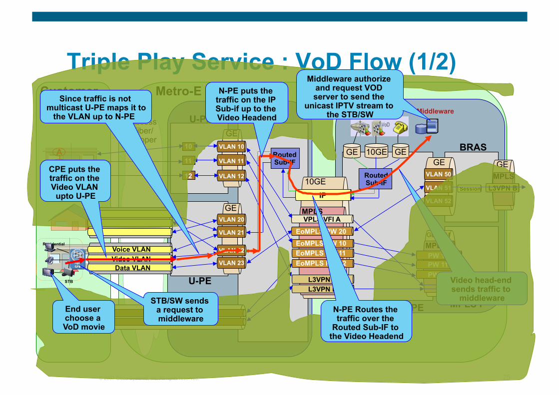
Triple Play Service : VoD Flow (1/2) Customer Premises
Metro-E SP Backbone
Access Fiber/
Copper
10GE
GE
GE
GE GE 10GE
N-PE
Head-end N-PE MPLS P
U-PE
U-PE
BRAS
Multicast Streaming
VLAN 200 VLAN 201
IP
MPLS
MPLS GE/STM
GE Routed Sub-IF
Routed Sub-IF
VLAN 10
VLAN 11
VLAN 12
VLAN 20
VLAN 21
VLAN 22
VLAN 23
EoMPLS PW 10 EoMPLS PW 11 EoMPLS PW 12
L3VPN A L3VPN B
VPLS VFI A
PW 10 PW 11
E
10
11
12
PW 12
Voice VLAN Video VLAN Data VLAN
EoMPLS PW 20
VLAN 50
VLAN 51
VLAN 52
Session L3VPN B MPLS GE B
A
F
C
Residential
STB
Middleware
Video head-end sends traffic to
middleware End user choose a VoD movie
Since traffic is not multicast U-PE maps it to
the VLAN up to N-PE
N-PE puts the traffic on the IP Sub-if up to the Video Headend
STB/SW sends a request to middleware
CPE puts the traffic on the Video VLAN
upto U-PE
N-PE Routes the traffic over the
Routed Sub-IF to the Video Headend
Middleware authorize and request VOD server to send the
unicast IPTV stream to the STB/SW
© 2007 Cisco Systems, Inc. All rights reserved. 76
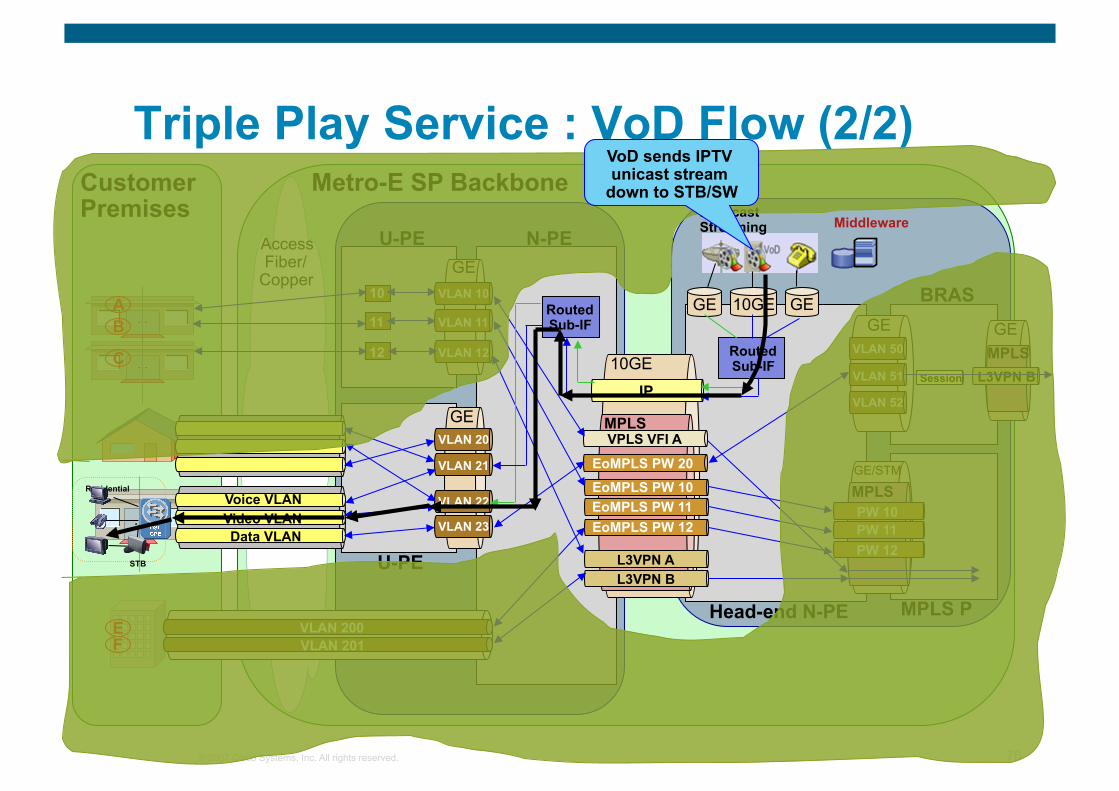
Triple Play Service : VoD Flow (2/2) Customer Premises
Metro-E SP Backbone
Access Fiber/
Copper
10GE
GE
GE
GE GE 10GE
N-PE
Head-end N-PE MPLS P
U-PE
U-PE
BRAS
Multicast Streaming
VLAN 200 VLAN 201
IP
MPLS
MPLS GE/STM
GE Routed Sub-IF
Routed Sub-IF
VLAN 10
VLAN 11
VLAN 12
VLAN 20
VLAN 21
VLAN 22
VLAN 23
EoMPLS PW 10 EoMPLS PW 11 EoMPLS PW 12
L3VPN A L3VPN B
VPLS VFI A
PW 10 PW 11
E
10
11
12
PW 12
Voice VLAN Video VLAN Data VLAN
EoMPLS PW 20
VLAN 50
VLAN 51
VLAN 52
Session L3VPN B MPLS GE B
A
F
C
Residential
STB
Middleware
VoD sends IPTV unicast stream
down to STB/SW
© 2007 Cisco Systems, Inc. All rights reserved. 77
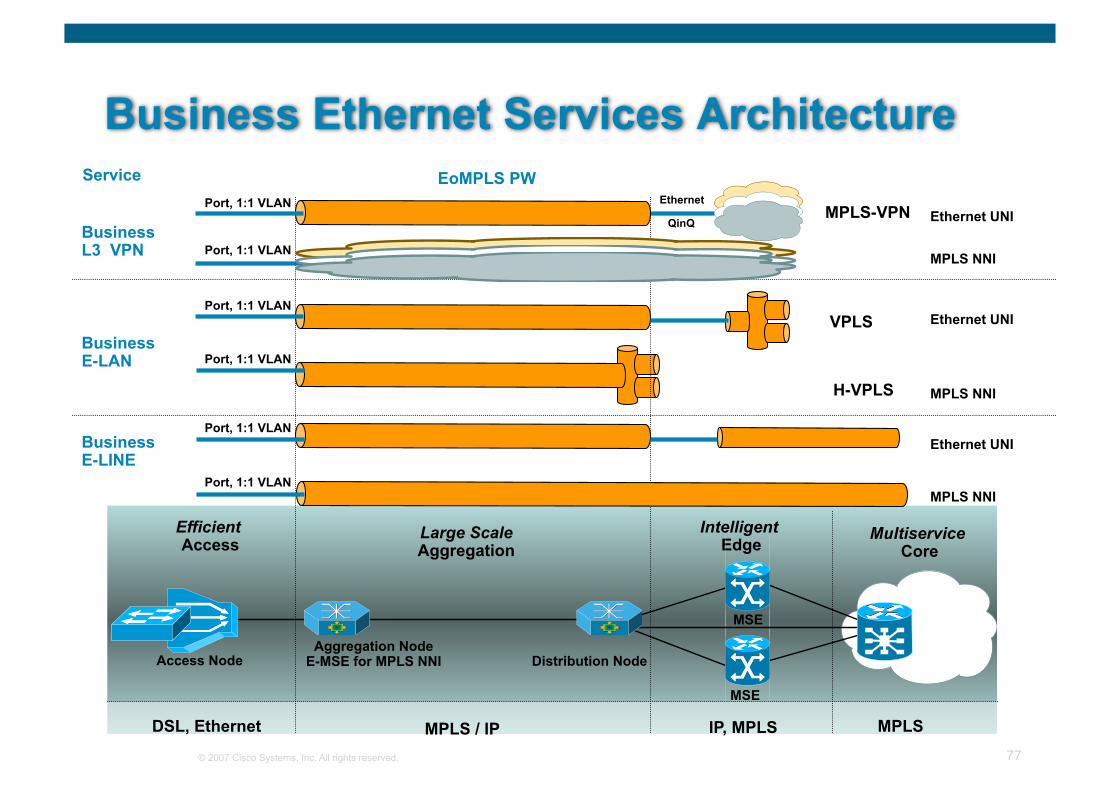
Business Ethernet Services Architecture
Large Scale Aggregation
Intelligent Edge
Multiservice Core
Efficient Access
IP, MPLS MPLS MPLS / IP DSL, Ethernet
Business E-LINE
Business E-LAN
EoMPLS PW EoMPLS Pseudowire VPLS
H-VPLS
Business L3 VPN
EoMPLS PW MPLS-VPN
MPLS NNI
MPLS NNI
MPLS NNI
EoMPLS PW Service
Ethernet UNI
Ethernet UNI
Ethernet UNI
Aggregation Node E-MSE for MPLS NNI
MSE
Access Node
MSE
Distribution Node
Port, 1:1 VLAN Ethernet
QinQ
Port, 1:1 VLAN
Port, 1:1 VLAN
Port, 1:1 VLAN
Port, 1:1 VLAN
Port, 1:1 VLAN
© 2007 Cisco Systems, Inc. All rights reserved. 78
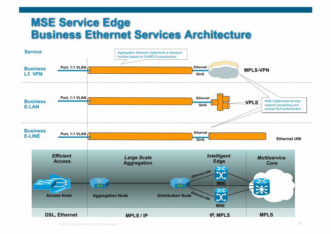
MSE Service Edge Business Ethernet Services Architecture
Large Scale Aggregation
Intelligent Edge
Multiservice Core
Efficient Access
IP, MPLS MPLS MPLS / IP DSL, Ethernet
Business E-LINE
Business E-LAN
EoMPLS PW EoMPLS Pseudowire VPLS
Business L3 VPN
EoMPLS PW MPLS-VPN
Service
Ethernet UNI
Aggregation Node
MSE
Access Node
MSE
Distribution Node
Aggregation Network implements a transport function based on EoMPLS pseudowires
Ethernet
QinQ
Ethernet
QinQ
Ethernet
QinQ
MSE implements service network forwarding and access SLA enforcement
MSE implements service network forwarding and access SLA enforcement
MSE implements service network forwarding and access SLA enforcement
Ethernet UNI
Port, 1:1 VLAN
Port, 1:1 VLAN
Port, 1:1 VLAN
© 2007 Cisco Systems, Inc. All rights reserved. 79
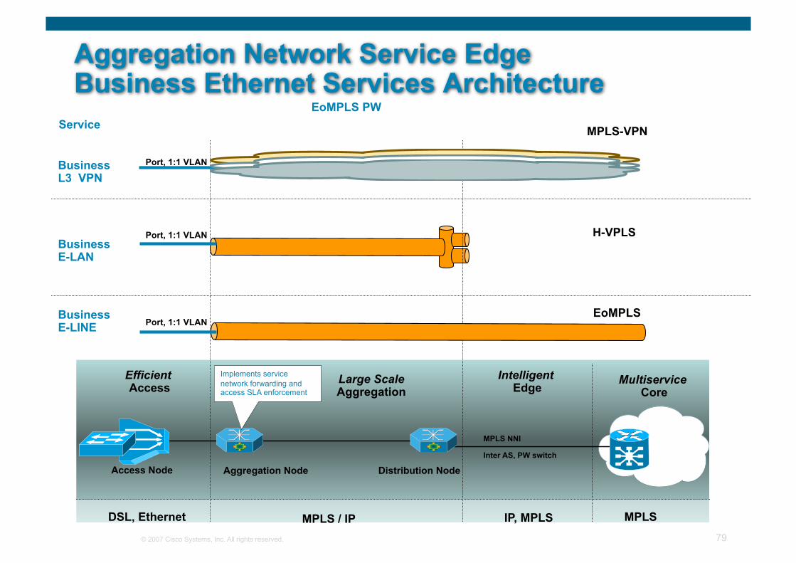
Aggregation Network Service Edge Business Ethernet Services Architecture
Large Scale Aggregation
Intelligent Edge
Multiservice Core
Efficient Access
IP, MPLS MPLS MPLS / IP DSL, Ethernet
Business E-LINE
Business E-LAN
H-VPLS
Business L3 VPN
EoMPLS PW MPLS-VPN
EoMPLS PW Service
Aggregation Node Access Node Distribution Node
EoMPLS
MPLS NNI
Inter AS, PW switch
Implements service network forwarding and access SLA enforcement
Port, 1:1 VLAN
Port, 1:1 VLAN
Port, 1:1 VLAN
© 2007 Cisco Systems, Inc. All rights reserved. 80
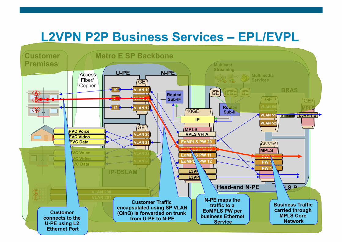
L2VPN P2P Business Services – EPL/EVPL Customer Premises
Metro E SP Backbone
Access Fiber/
Copper
10GE
GE
GE
GE GE 10GE
N-PE
Head-end N-PE MPLS P
U-PE
IP-DSLAM
BRAS
Multimedia Services
Multicast Streaming
VLAN 200 VLAN 201
IP
MPLS
MPLS GE/STM
GE Routed Sub-IF
Routed Sub-IF
VLAN 10
VLAN 11
VLAN 12
VLAN 20
VLAN 21
VLAN 22
VLAN 23
EoMPLS PW 10 EoMPLS PW 11 EoMPLS PW 12
L3VPN A L3VPN B
VPLS VFI A
PW 10 PW 11
E
10
11
12
PW 12
PVC Voice PVC Video PVC Data
PVC Voice PVC Video PVC Data
EoMPLS PW 20
VLAN 50
VLAN 51
VLAN 52
Session L3VPN B MPLS GE B
A
F
C
Customer connects to the U-PE using L2 Ethernet Port
Customer Traffic encapsulated using SP VLAN (QinQ) is forwarded on trunk
from U-PE to N-PE
N-PE maps the traffic to a
EoMPLS PW per business Ethernet
Service
Business Traffic carried through
MPLS Core Network
© 2007 Cisco Systems, Inc. All rights reserved. 81
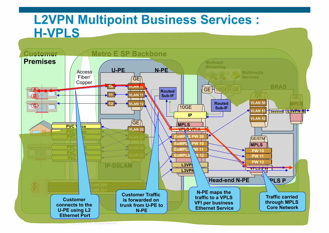
L2VPN Multipoint Business Services : H-VPLS
Customer Premises
Metro E SP Backbone
Access Fiber/
Copper
10GE
GE
GE
GE GE 10GE
N-PE
Head-end N-PE MPLS P
U-PE
IP-DSLAM
BRAS
Multimedia Services
Multicast Streaming
VLAN 200 VLAN 201
IP
MPLS
MPLS GE/STM
GE Routed Sub-IF
Routed Sub-IF
VLAN 10
VLAN 11
VLAN 12
VLAN 20
VLAN 21
VLAN 22
VLAN 23
EoMPLS PW 10 EoMPLS PW 11 EoMPLS PW 12
L3VPN A L3VPN B
VPLS VFI A
PW 10 PW 11
E
10
11
12
PW 12
PVC Voice PVC Video PVC Data
PVC Voice PVC Video PVC Data
EoMPLS PW 20
VLAN 50
VLAN 51
VLAN 52
Session L3VPN B MPLS GE B
A
F
C
VPLS PW
Customer connects to the U-PE using L2 Ethernet Port
Customer Traffic is forwarded on
trunk from U-PE to N-PE
N-PE maps the traffic to a VPLS VFI per business Ethernet Service
Traffic carried through MPLS Core Network
© 2007 Cisco Systems, Inc. All rights reserved. 82
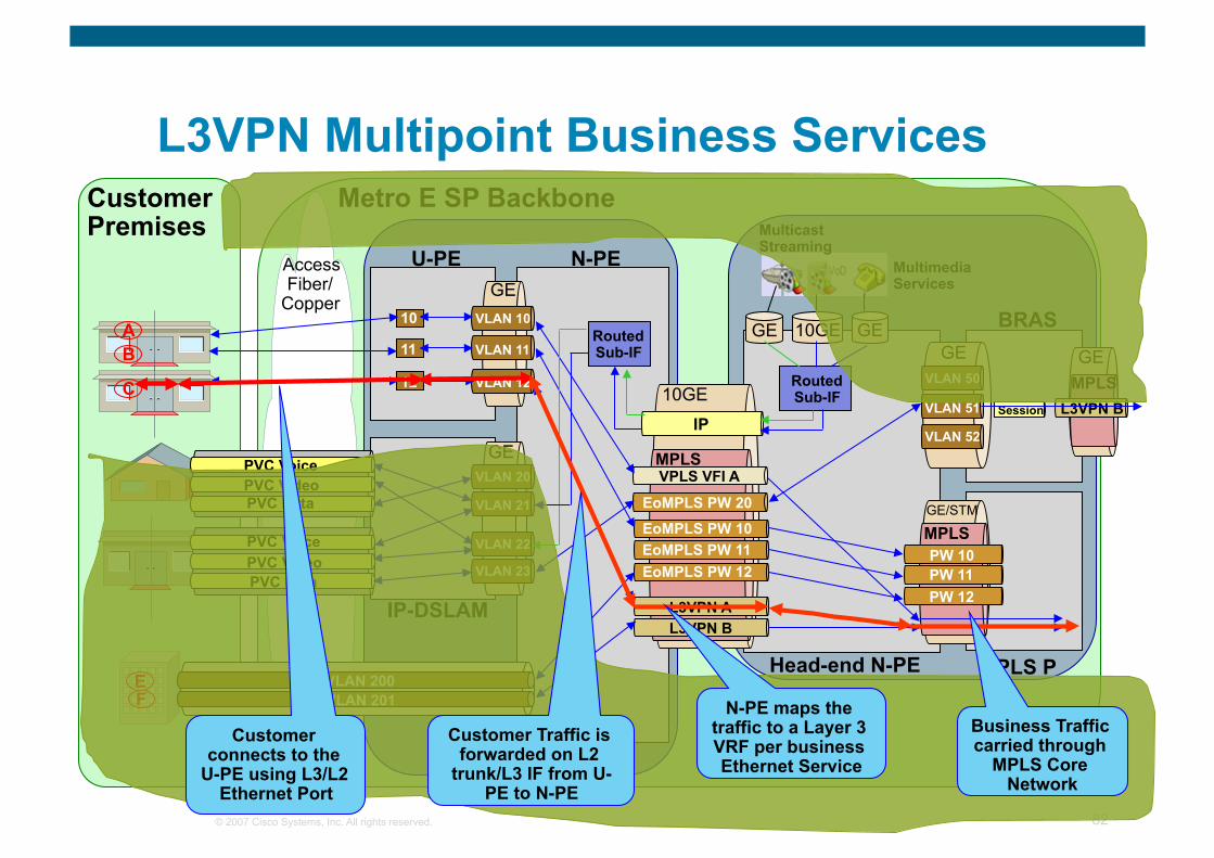
L3VPN Multipoint Business Services Customer Premises
Access Fiber/
Copper
10GE
GE
GE
GE GE 10GE
N-PE
Head-end N-PE MPLS P
U-PE
IP-DSLAM
BRAS
Multimedia Services
Multicast Streaming
VLAN 200 VLAN 201
IP
MPLS
MPLS GE/STM
GE Routed Sub-IF
Routed Sub-IF
VLAN 10
VLAN 11
VLAN 12
VLAN 20
VLAN 21
VLAN 22
VLAN 23
EoMPLS PW 10 EoMPLS PW 11 EoMPLS PW 12
L3VPN A L3VPN B
VPLS VFI A
PW 10 PW 11
E
10
11
12
PW 12
PVC Voice PVC Video PVC Data
PVC Voice PVC Video PVC Data
EoMPLS PW 20
VLAN 50
VLAN 51
VLAN 52
Session L3VPN B MPLS GE B
A
F
C
Metro E SP Backbone
Customer connects to the
U-PE using L3/L2 Ethernet Port
N-PE maps the traffic to a Layer 3 VRF per business Ethernet Service
Business Traffic carried through
MPLS Core Network
Customer Traffic is forwarded on L2
trunk/L3 IF from U-PE to N-PE
© 2007 Cisco Systems, Inc. All rights reserved. 83
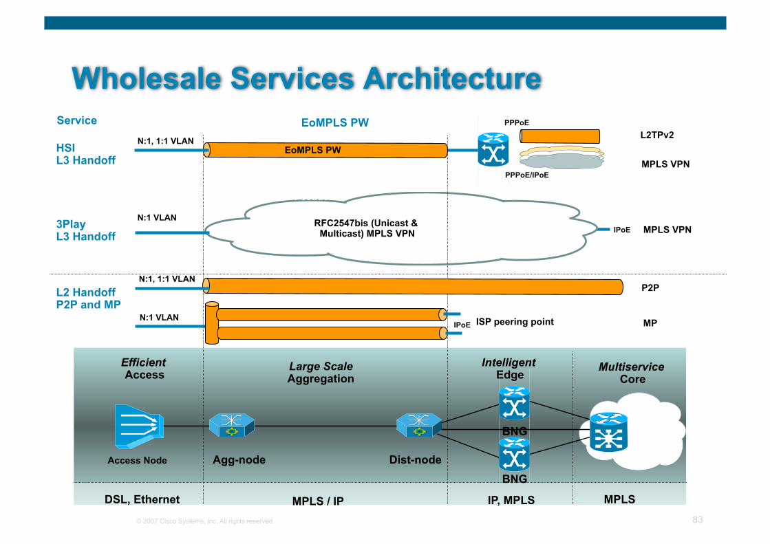
Wholesale Services Architecture
Large Scale Aggregation
Intelligent Edge
Multiservice Core
Efficient Access
Agg-node BNG
IP, MPLS MPLS MPLS / IP DSL, Ethernet
Access Node
BNG
Dist-node
L2 Handoff P2P and MP
3Play L3 Handoff
EoMPLS Pseudowire
HSI L3 Handoff
EoMPLS PW
MPLS VPN
EoMPLS PW Service
MP
L2TPv2
RFC2547bis (Unicast & Multicast) MPLS VPN
ISP peering point
N:1, 1:1 VLAN
N:1 VLAN
N:1, 1:1 VLAN
N:1 VLAN
PPPoE
PPPoE/IPoE
IPoE
EoMPLS PW
P2P
MPLS VPN IPoE
© 2007 Cisco Systems, Inc. All rights reserved. 84
Summary
You have an understanding of Metro Ethernet technology and its services now.
You have the fundamental understanding of how different services work in a Metro-E network.
You have the basic knowledge of different control & data plane technology options for building a Metro-E network.

© 2007 Cisco Systems, Inc. All rights reserved. 85
Questions ?
© 2007 Cisco Systems, Inc. All rights reserved. Cisco Confidential 86
Ethernet OAM
© 2007 Cisco Systems, Inc. All rights reserved. 87
Agenda
Review - OAM In General
Ethernet OAM Protocol Overview IEEE 802.1ag – CFM
ITU Y.1731
IEEE 802.3ah (clause 57) – Link OAM (EFM)
MEF E-LMI
Ethernet OAM Fault Management
Fault Management Scenarios
Summary

© 2007 Cisco Systems, Inc. All rights reserved. Cisco Confidential 88
Review: OAM in General
© 2007 Cisco Systems, Inc. All rights reserved. 89
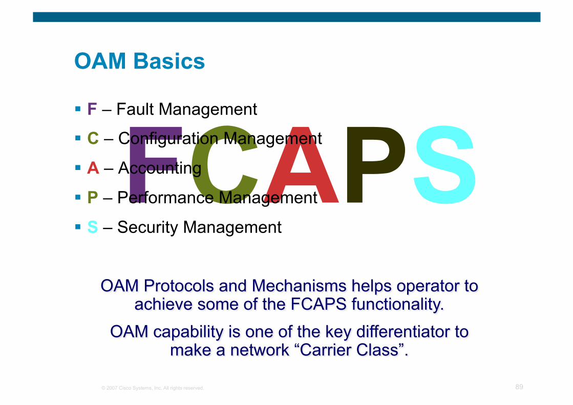
OAM Basics
FCAPS F – Fault Management
C – Configuration Management
A – Accounting
P – Performance Management
S – Security Management
© 2007 Cisco Systems, Inc. All rights reserved. 90
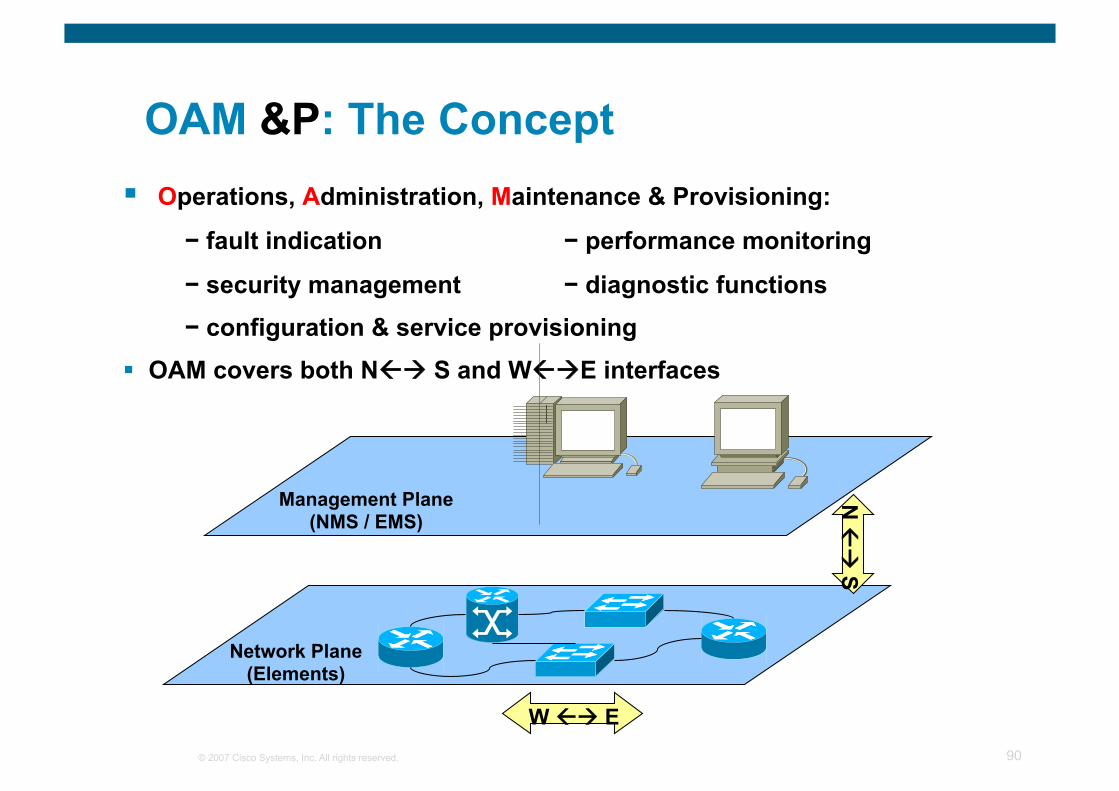
OAM &P: The Concept Operations, Administration, Maintenance & Provisioning:
− fault indication − performance monitoring
− security management − diagnostic functions − configuration & service provisioning
OAM covers both N S and WE interfaces
Network Plane (Elements)
Management Plane (NMS / EMS)
N
S
W E
© 2007 Cisco Systems, Inc. All rights reserved. 91
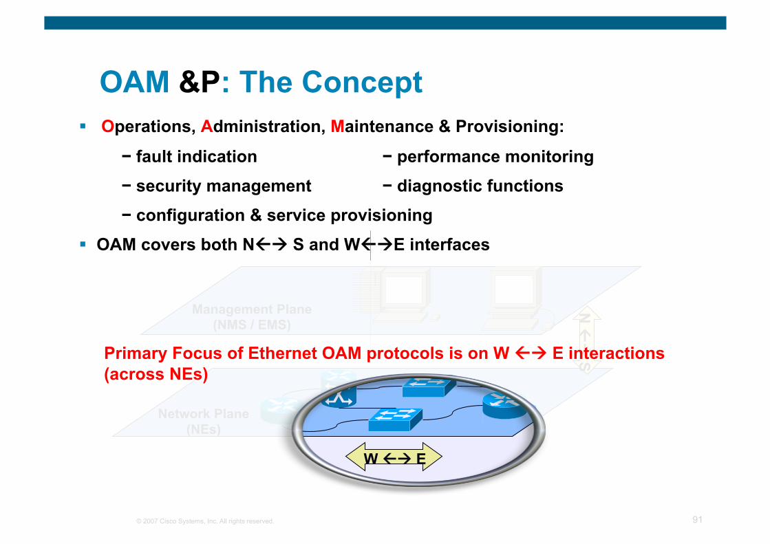
OAM &P: The Concept Operations, Administration, Maintenance & Provisioning:
− fault indication − performance monitoring − security management − diagnostic functions − configuration & service provisioning
OAM covers both N S and WE interfaces
Network Plane (NEs)
Management Plane (NMS / EMS)
N
S
W E
Primary Focus of Ethernet OAM protocols is on W E interactions (across NEs)

© 2007 Cisco Systems, Inc. All rights reserved. Cisco Confidential 92
Ethernet OAM Protocol Overview
© 2007 Cisco Systems, Inc. All rights reserved. 93
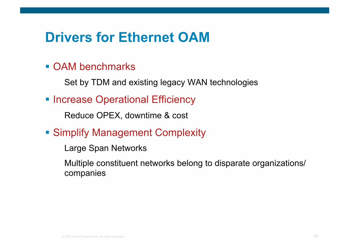
Drivers for Ethernet OAM
OAM benchmarks Set by TDM and existing legacy WAN technologies
Increase Operational Efficiency Reduce OPEX, downtime & cost
Simplify Management Complexity Large Span Networks
Multiple constituent networks belong to disparate organizations/companies
© 2007 Cisco Systems, Inc. All rights reserved. 94
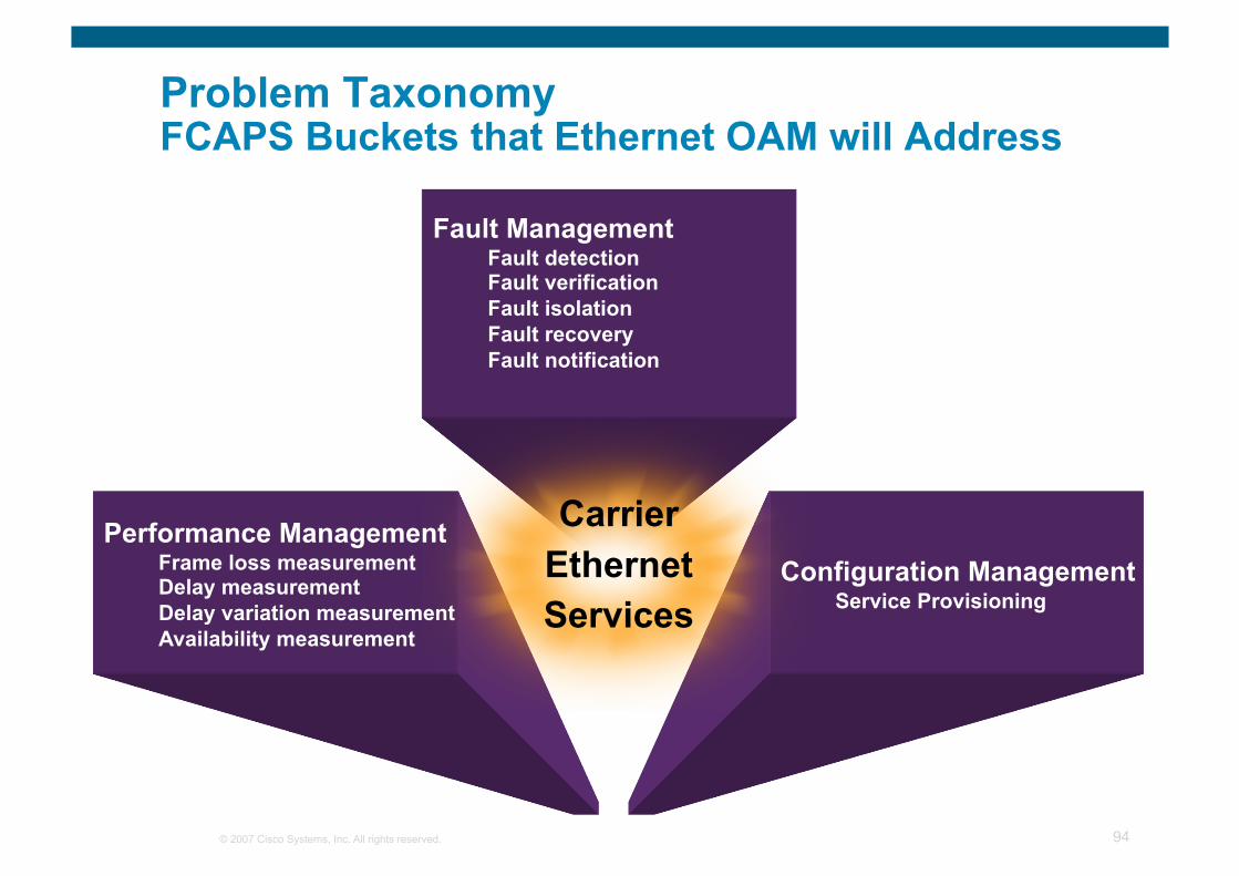
Problem Taxonomy FCAPS Buckets that Ethernet OAM will Address
Fault Management Fault detection Fault verification Fault isolation Fault recovery Fault notification
Configuration Management Service Provisioning
Performance Management Frame loss measurement Delay measurement Delay variation measurement Availability measurement
Carrier Ethernet Services
© 2007 Cisco Systems, Inc. All rights reserved. 95
802.1ag
802.3ah
E-LMI Y.1731 Cisco
IP SLA’s
Fault Management
Performance Management
Configuration Management
Configuration Management
Fault Management
Performance Management
Configuration Management
Performance Management
Fault Management
Performance Management
Configuration Management
Fault Management
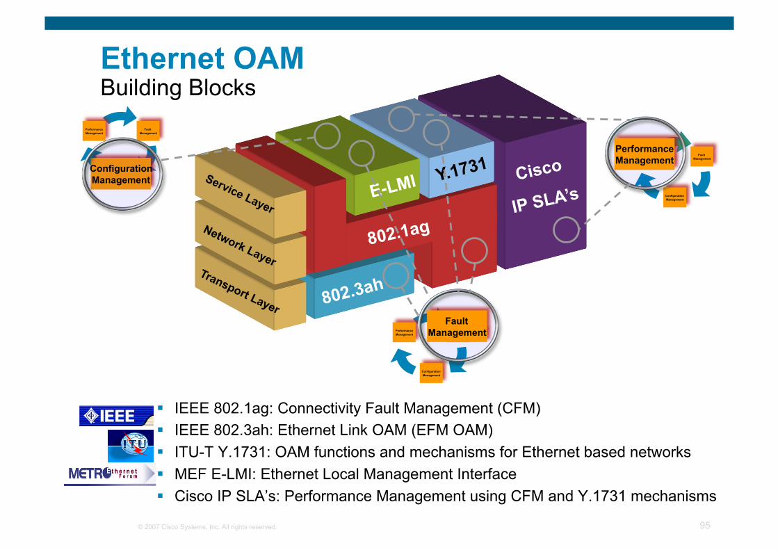
Ethernet OAM Building Blocks
IEEE 802.1ag: Connectivity Fault Management (CFM) IEEE 802.3ah: Ethernet Link OAM (EFM OAM) ITU-T Y.1731: OAM functions and mechanisms for Ethernet based networks MEF E-LMI: Ethernet Local Management Interface Cisco IP SLA’s: Performance Management using CFM and Y.1731 mechanisms
© 2007 Cisco Systems, Inc. All rights reserved. 96
Access Access Core Customer Customer
UNI UNI NNI NNI NNI
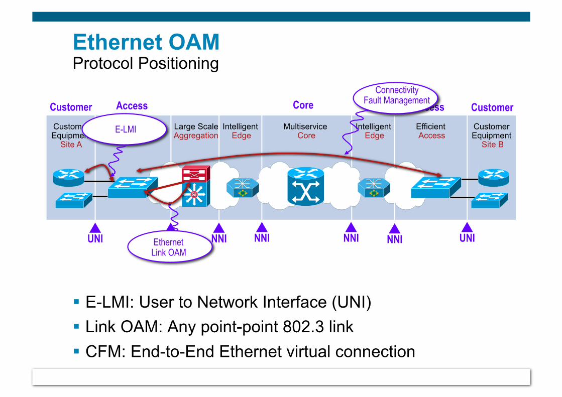
Ethernet OAM Protocol Positioning
E-LMI: User to Network Interface (UNI) Link OAM: Any point-point 802.3 link CFM: End-to-End Ethernet virtual connection
Large Scale Aggregation
Intelligent Edge
Multiservice Core
Efficient Access
Intelligent Edge
Efficient Access
Customer Equipment
Site A
Customer Equipment
Site B
NNI NNI
E-LMI
Ethernet Link OAM
Connectivity Fault Management
© 2007 Cisco Systems, Inc. All rights reserved. Cisco Confidential 97
IEEE 802.1ag Connectivity Fault Management (CFM)
© 2007 Cisco Systems, Inc. All rights reserved. 98
Connectivity Fault Management (CFM) Overview
Family of protocols that provides capabilities to detect, verify, isolate and report ethernet connectivity faults
Employs regular Ethernet frames that travel in-band with the customer traffic
Devices that cannot interpret CFM Messages forward them as normal data frames
Under standardization by IEEE (P802.1ag) Now at Sponsor Ballot stage (expected ratification 2HCY07)
As of 09/26/07, CFM is now standard (IEEE std. 802.1ag-2007) Draft 8.1 was the final draft
© 2007 Cisco Systems, Inc. All rights reserved. 99
CFM Overview (Cont.)
Key CFM mechanisms include: Nested Maintenance Domains (MDs) that break up the responsibilities for network administration of a given end-to-end service
Maintenance Associations (MAs) that monitor service instances under a given MD
Maintenance Points (MPs) that generate and respond to CFM PDUs
Protocols (Continuity Check, Loopback and Linktrace) used for Fault Management activities
© 2007 Cisco Systems, Inc. All rights reserved. 100
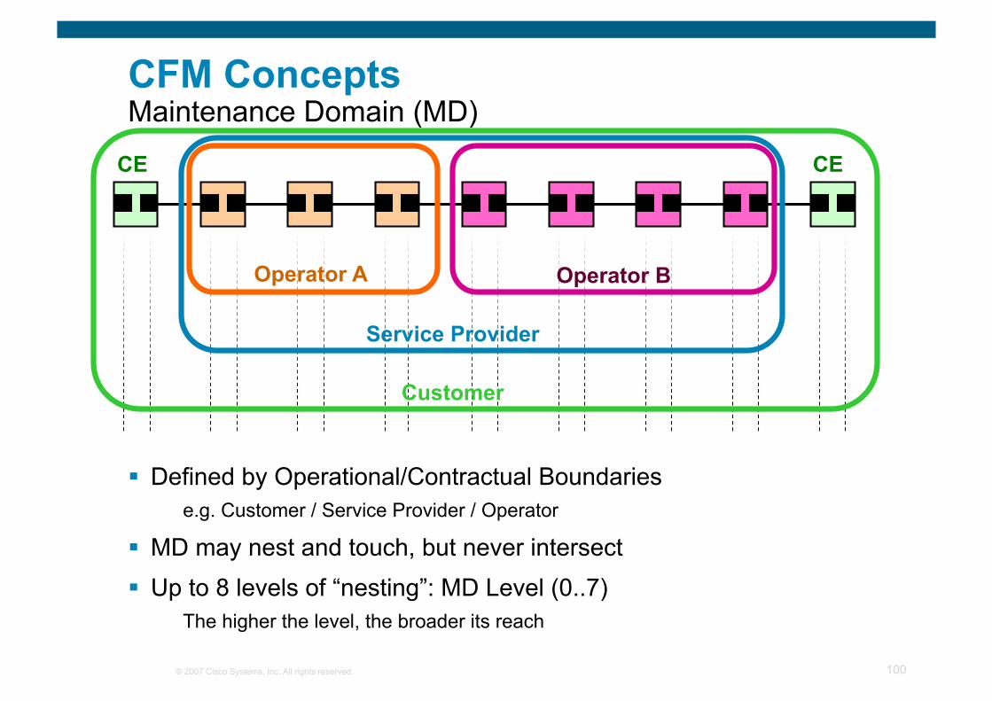
CFM Concepts Maintenance Domain (MD)
CE CE
Defined by Operational/Contractual Boundaries e.g. Customer / Service Provider / Operator
MD may nest and touch, but never intersect Up to 8 levels of “nesting”: MD Level (0..7)
The higher the level, the broader its reach
Operator A Operator B
Service Provider
Customer
© 2007 Cisco Systems, Inc. All rights reserved. 101
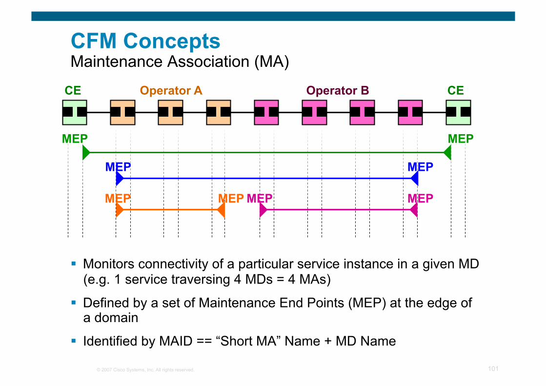
CFM Concepts Maintenance Association (MA)
CE CE Operator A Operator B
MEP MEP
MEP MEP
MEP MEP MEP MEP
Monitors connectivity of a particular service instance in a given MD (e.g. 1 service traversing 4 MDs = 4 MAs)
Defined by a set of Maintenance End Points (MEP) at the edge of a domain
Identified by MAID == “Short MA” Name + MD Name
© 2007 Cisco Systems, Inc. All rights reserved. 102
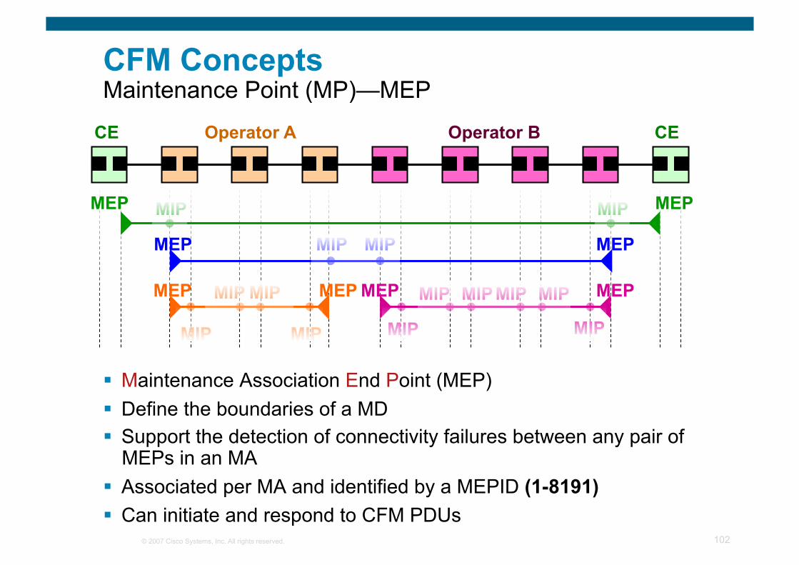
CFM Concepts Maintenance Point (MP)—MEP
Maintenance Association End Point (MEP) Define the boundaries of a MD Support the detection of connectivity failures between any pair of
MEPs in an MA Associated per MA and identified by a MEPID (1-8191) Can initiate and respond to CFM PDUs
CE CE Operator A Operator B
MEP MEP MIP MIP
MEP MEP MIP MIP
MEP MEP MEP MEP
MIP MIP
MIP MIP
MIP MIP
MIP MIP MIP MIP
© 2007 Cisco Systems, Inc. All rights reserved. 103
CE CE Operator A Operator B
MEP MEP MIP MIP
MEP MEP MIP MIP
MEP MEP MEP MEP
MIP MIP
MIP MIP
MIP MIP
MIP MIP MIP MIP
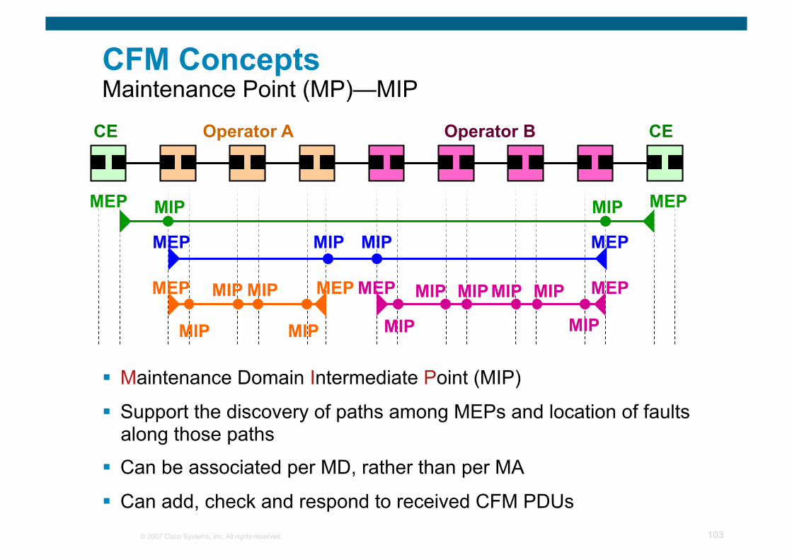
CFM Concepts Maintenance Point (MP)—MIP
Maintenance Domain Intermediate Point (MIP)
Support the discovery of paths among MEPs and location of faults along those paths
Can be associated per MD, rather than per MA
Can add, check and respond to received CFM PDUs
© 2007 Cisco Systems, Inc. All rights reserved. 104
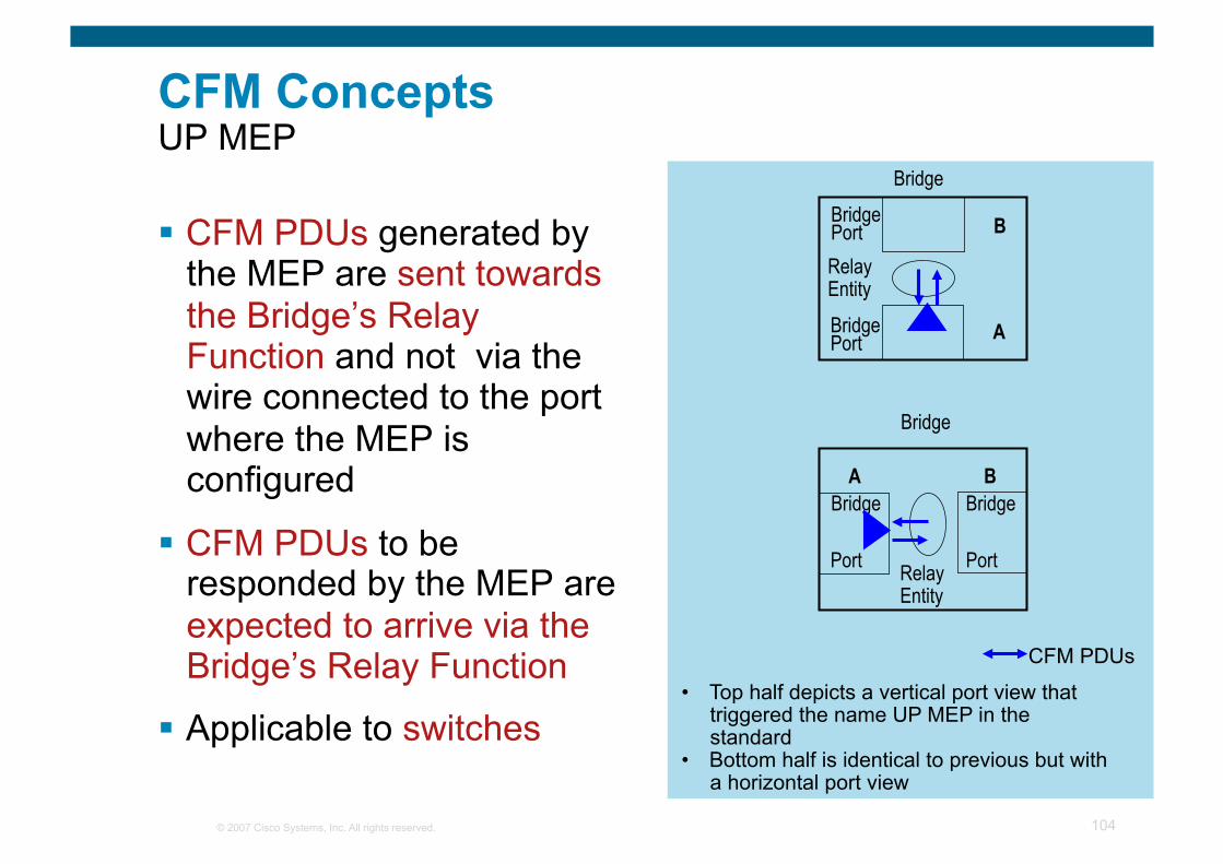
CFM Concepts UP MEP
CFM PDUs generated by the MEP are sent towards the Bridge’s Relay Function and not via the wire connected to the port where the MEP is configured
CFM PDUs to be responded by the MEP are expected to arrive via the Bridge’s Relay Function
Applicable to switches
Bridge
Port
Bridge
Relay Entity
Bridge
Port
Bridge
Relay Entity
Port Bridge
Port Bridge
B
A
A B
CFM PDUs
• Top half depicts a vertical port view that triggered the name UP MEP in the standard
• Bottom half is identical to previous but with a horizontal port view
© 2007 Cisco Systems, Inc. All rights reserved. 105
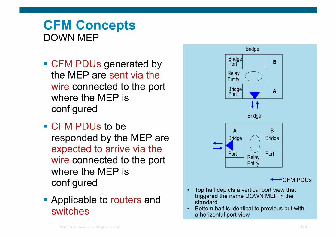
CFM Concepts DOWN MEP
CFM PDUs generated by the MEP are sent via the wire connected to the port where the MEP is configured
CFM PDUs to be responded by the MEP are expected to arrive via the wire connected to the port where the MEP is configured
Applicable to routers and switches
Bridge
Port
Bridge
Relay Entity
Bridge
Port
Bridge
Relay Entity
Port Bridge
Port Bridge
B
A
A B
CFM PDUs
• Top half depicts a vertical port view that triggered the name DOWN MEP in the standard
• Bottom half is identical to previous but with a horizontal port view
© 2007 Cisco Systems, Inc. All rights reserved. 106
Monitored area
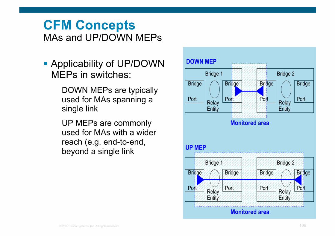
CFM Concepts MAs and UP/DOWN MEPs
Applicability of UP/DOWN MEPs in switches:
DOWN MEPs are typically used for MAs spanning a single link
UP MEPs are commonly used for MAs with a wider reach (e.g. end-to-end, beyond a single link
Bridge
Port
Bridge 1
Relay Entity
Bridge
Port
Bridge
Port
Bridge 2
Relay Entity
Bridge
Port
Monitored area
Bridge
Port
Bridge 1
Relay Entity
Bridge
Port
Bridge
Port
Bridge 2
Relay Entity
Bridge
Port
UP MEP
DOWN MEP
© 2007 Cisco Systems, Inc. All rights reserved. 107
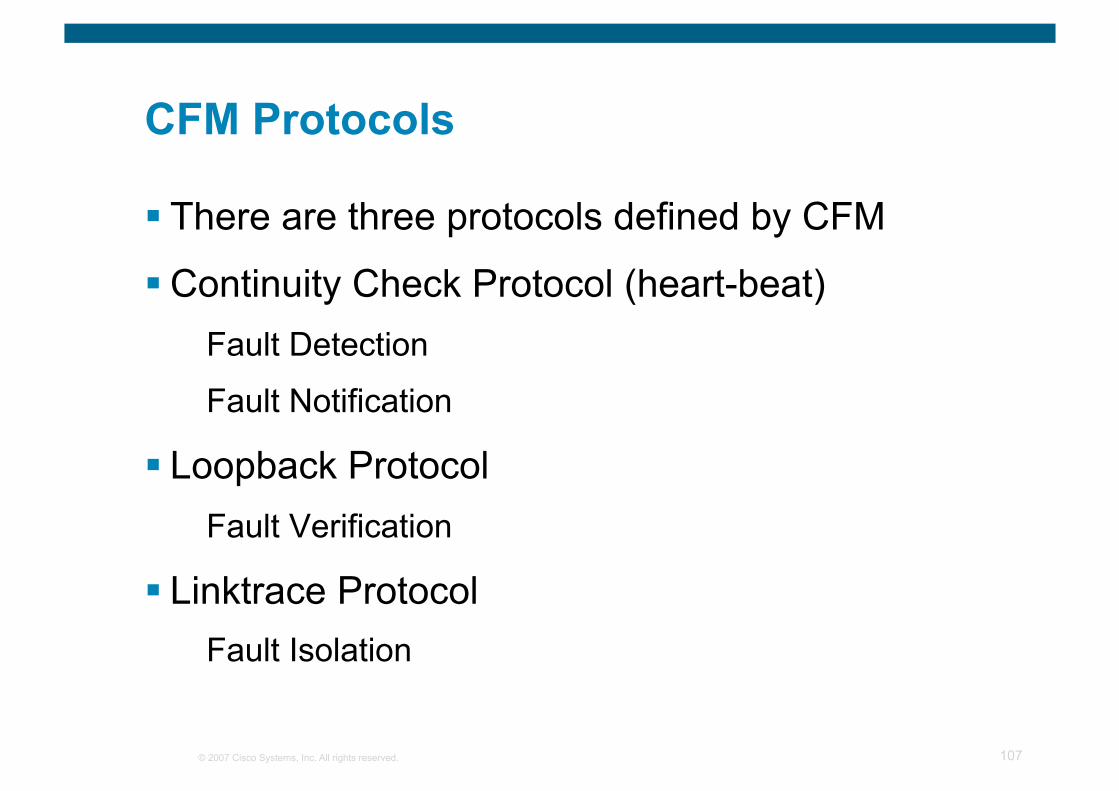
CFM Protocols
There are three protocols defined by CFM
Continuity Check Protocol (heart-beat) Fault Detection
Fault Notification
Loopback Protocol Fault Verification
Linktrace Protocol Fault Isolation
© 2007 Cisco Systems, Inc. All rights reserved. 108
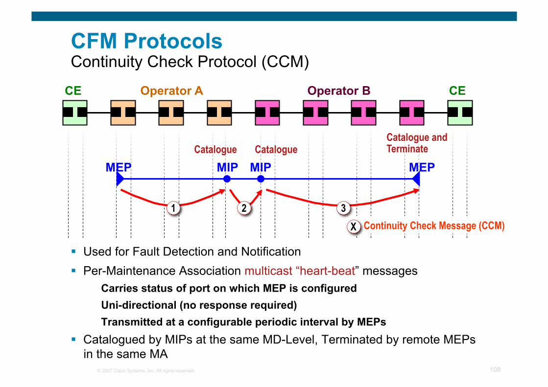
CFM Protocols Continuity Check Protocol (CCM)
CE CE Operator A Operator B
MEP MEP MIP MIP Catalogue Catalogue
Catalogue and Terminate
1 2 3 1. Continuity Check Message (CCM) X
Used for Fault Detection and Notification Per-Maintenance Association multicast “heart-beat” messages
Carries status of port on which MEP is configured Uni-directional (no response required) Transmitted at a configurable periodic interval by MEPs
Catalogued by MIPs at the same MD-Level, Terminated by remote MEPs in the same MA
© 2007 Cisco Systems, Inc. All rights reserved. 109
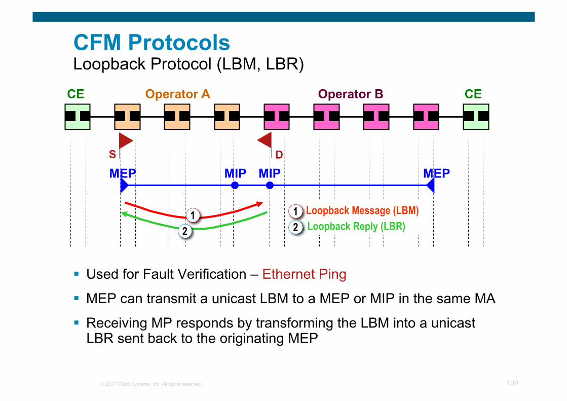
CFM Protocols Loopback Protocol (LBM, LBR)
CE CE Operator A Operator B
MEP MEP MIP MIP S D
1. Loopback Message (LBM) 2. Loopback Reply (LBR)
1 2
1 2
Used for Fault Verification – Ethernet Ping
MEP can transmit a unicast LBM to a MEP or MIP in the same MA
Receiving MP responds by transforming the LBM into a unicast LBR sent back to the originating MEP
© 2007 Cisco Systems, Inc. All rights reserved. 110
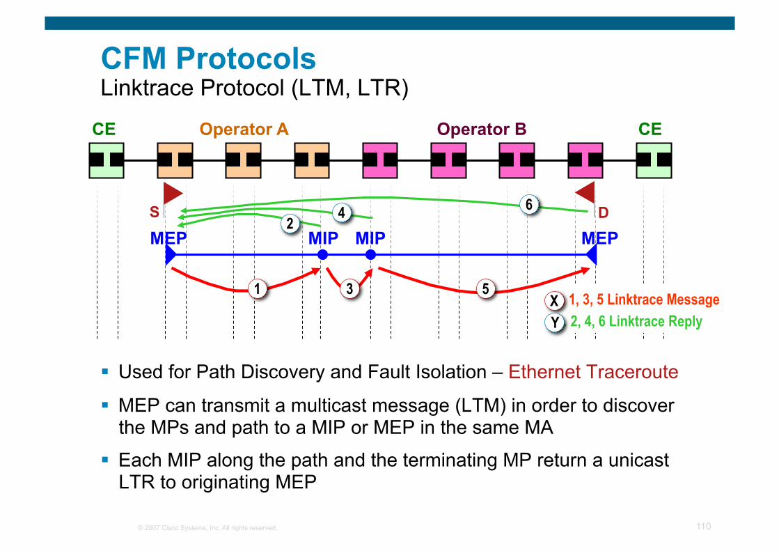
CFM Protocols Linktrace Protocol (LTM, LTR)
Used for Path Discovery and Fault Isolation – Ethernet Traceroute
MEP can transmit a multicast message (LTM) in order to discover the MPs and path to a MIP or MEP in the same MA
Each MIP along the path and the terminating MP return a unicast LTR to originating MEP
CE CE Operator A Operator B
MEP MEP MIP MIP S D
1 3 5
2 4 6
1. 1, 3, 5 Linktrace Message 2. 2, 4, 6 Linktrace Reply
X Y
© 2007 Cisco Systems, Inc. All rights reserved. 111
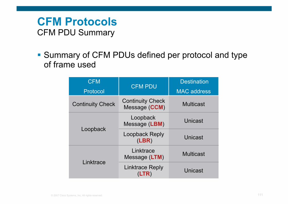
CFM Protocols CFM PDU Summary
Summary of CFM PDUs defined per protocol and type of frame used
CFM
Protocol CFM PDU
Destination
MAC address
Continuity Check Continuity Check Message (CCM) Multicast
Loopback
Loopback Message (LBM) Unicast
Loopback Reply (LBR) Unicast
Linktrace
Linktrace Message (LTM) Multicast
Linktrace Reply (LTR) Unicast
© 2007 Cisco Systems, Inc. All rights reserved. 112
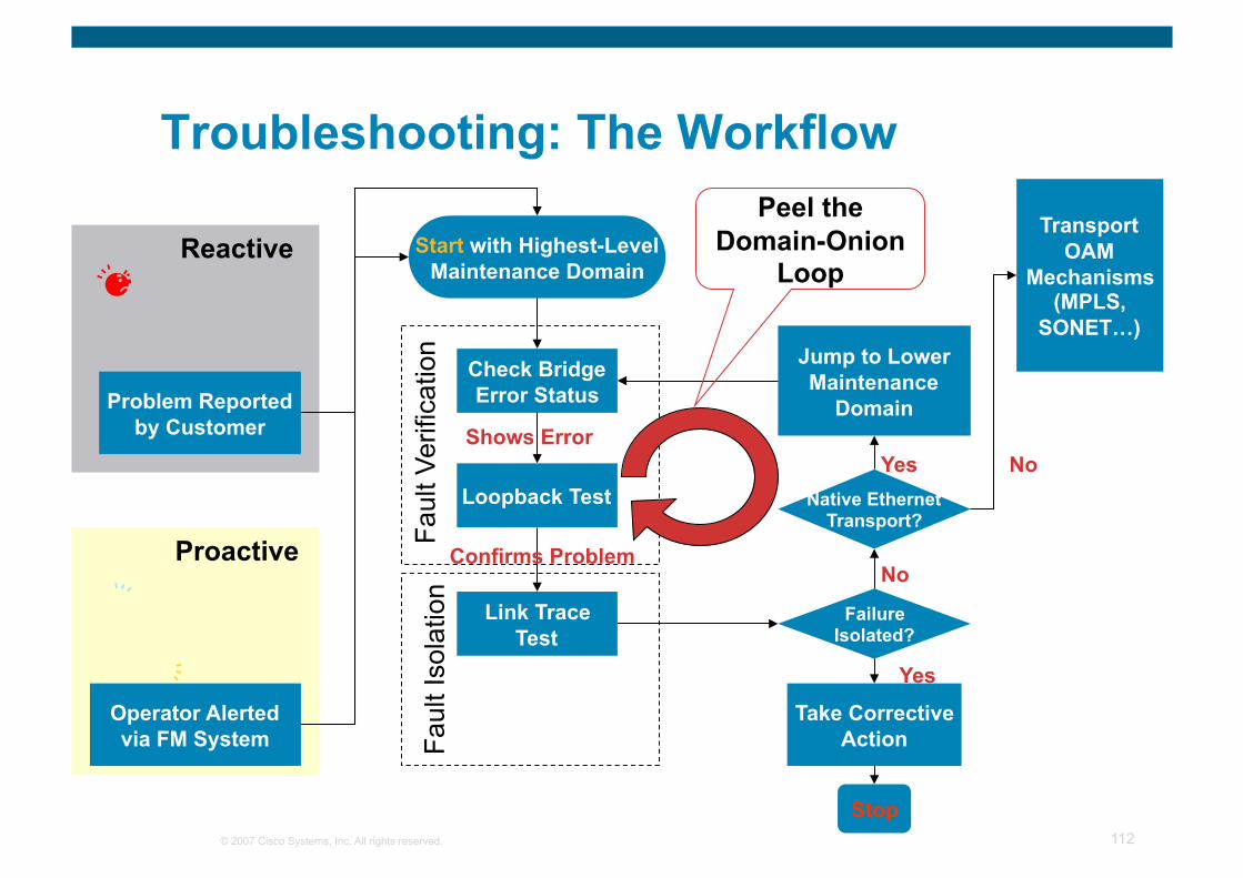
Troubleshooting: The Workflow
Start with Highest-Level Maintenance Domain
Check Bridge Error Status
Failure Isolated?
Take Corrective Action
Stop
Shows Error
Yes
No Confirms Problem
Jump to Lower Maintenance
Domain Fa
ult V
erifi
catio
n Fa
ult I
sola
tion
Loopback Test
Link Trace Test
Native Ethernet Transport?
Yes No
Transport OAM
Mechanisms (MPLS,
SONET…)
Peel the Domain-Onion
Loop
Problem Reported by Customer
Reactive
Operator Alerted via FM System
Proactive
© 2007 Cisco Systems, Inc. All rights reserved. Cisco Confidential 113
ITU Y.1731 OAM Functions and Mechanisms for Ethernet-Based Networks
© 2007 Cisco Systems, Inc. All rights reserved. 114
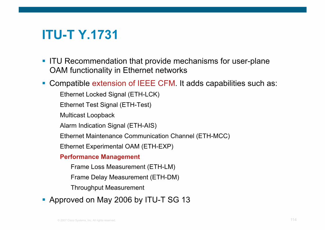
ITU-T Y.1731
ITU Recommendation that provide mechanisms for user-plane OAM functionality in Ethernet networks
Compatible extension of IEEE CFM. It adds capabilities such as: Ethernet Locked Signal (ETH-LCK) Ethernet Test Signal (ETH-Test) Multicast Loopback Alarm Indication Signal (ETH-AIS) Ethernet Maintenance Communication Channel (ETH-MCC) Ethernet Experimental OAM (ETH-EXP) Performance Management
Frame Loss Measurement (ETH-LM) Frame Delay Measurement (ETH-DM) Throughput Measurement
Approved on May 2006 by ITU-T SG 13
© 2007 Cisco Systems, Inc. All rights reserved. 115
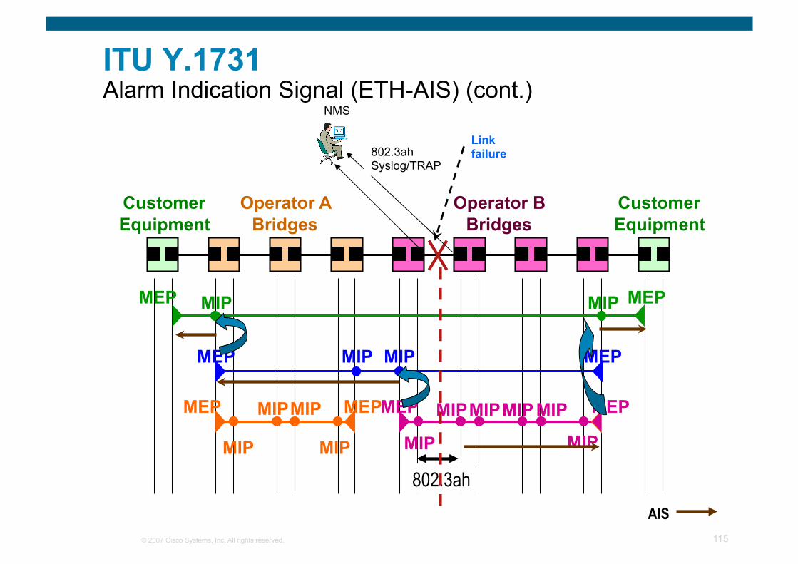
ITU Y.1731 Alarm Indication Signal (ETH-AIS) (cont.)
Customer Equipment
Customer Equipment
Operator A Bridges
Operator B Bridges
MEP MEP
MEP MEP
MEP MEP MEP MEP
MIP
MIP MIP
MIP
MIP MIP
MIP MIP
MIP MIP
MIP MIP MIP MIP
Link failure
NMS
802.3ah AIS
802.3ah Syslog/TRAP
© 2007 Cisco Systems, Inc. All rights reserved. 116
IEEE 802.3ah (Clause 57) Link OAM
© 2007 Cisco Systems, Inc. All rights reserved. 117
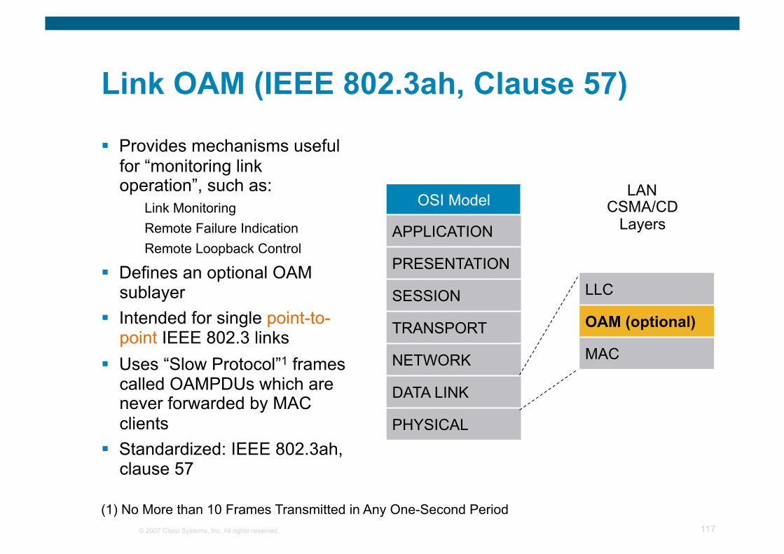
Link OAM (IEEE 802.3ah, Clause 57)
Provides mechanisms useful for “monitoring link operation”, such as:
Link Monitoring Remote Failure Indication Remote Loopback Control
Defines an optional OAM sublayer
Intended for single point-to-point IEEE 802.3 links
Uses “Slow Protocol”1 frames called OAMPDUs which are never forwarded by MAC clients
Standardized: IEEE 802.3ah, clause 57
OSI Model
APPLICATION
PRESENTATION
SESSION
TRANSPORT
NETWORK
DATA LINK
PHYSICAL
LLC
OAM (optional)
MAC
LAN CSMA/CD
Layers
(1) No More than 10 Frames Transmitted in Any One-Second Period
© 2007 Cisco Systems, Inc. All rights reserved. 118
IEEE 802.3ah Key Functions
OAM Discovery Discover OAM support and capabilities per device
Link monitoring Basic error definitions for Ethernet so entities can detect failed and degraded connections
Fault Signaling mechanisms for one entity to signal another that it has detected an error
Remote loopback used to troubleshoot networks, allows one station to put the other station into a state whereby all inbound traffic is immediately reflected back onto the link
© 2007 Cisco Systems, Inc. All rights reserved. 119
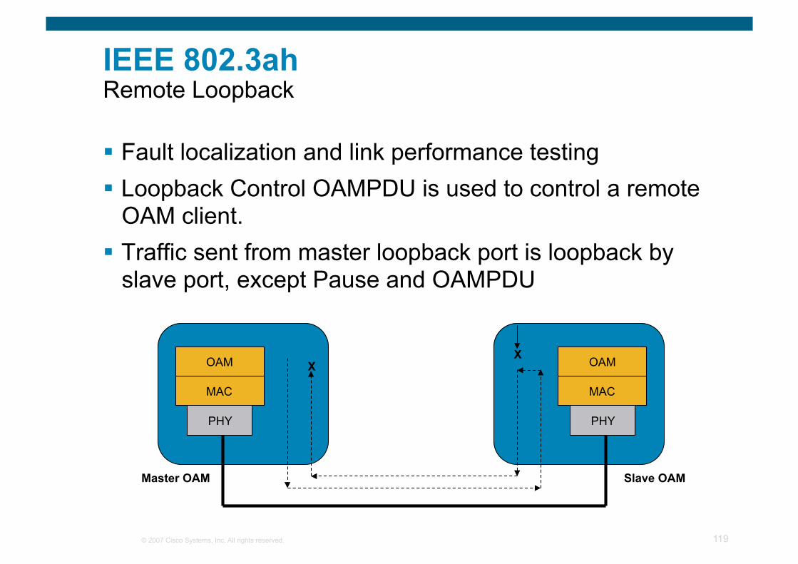
IEEE 802.3ah Remote Loopback
Fault localization and link performance testing Loopback Control OAMPDU is used to control a remote
OAM client. Traffic sent from master loopback port is loopback by
slave port, except Pause and OAMPDU
OAM
MAC
PHY
OAM
MAC
PHY
X X
Master OAM Slave OAM

© 2007 Cisco Systems, Inc. All rights reserved. 120
MEF Ethernet Local Management Interface (E-LMI)
© 2007 Cisco Systems, Inc. All rights reserved. 121
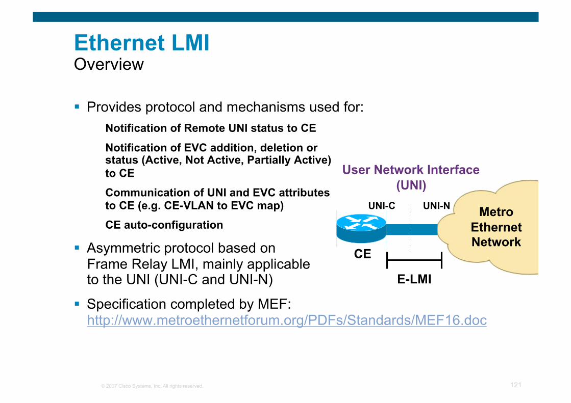
Ethernet LMI Overview
Provides protocol and mechanisms used for: Notification of Remote UNI status to CE
Notification of EVC addition, deletion or status (Active, Not Active, Partially Active) to CE Communication of UNI and EVC attributes to CE (e.g. CE-VLAN to EVC map) CE auto-configuration
Asymmetric protocol based on Frame Relay LMI, mainly applicable to the UNI (UNI-C and UNI-N)
Specification completed by MEF: http://www.metroethernetforum.org/PDFs/Standards/MEF16.doc
CE
User Network Interface (UNI)
UNI-C UNI-N
E-LMI
Metro Ethernet Network
© 2007 Cisco Systems, Inc. All rights reserved. 122
Cisco’s IP SLA
© 2007 Cisco Systems, Inc. All rights reserved. 123
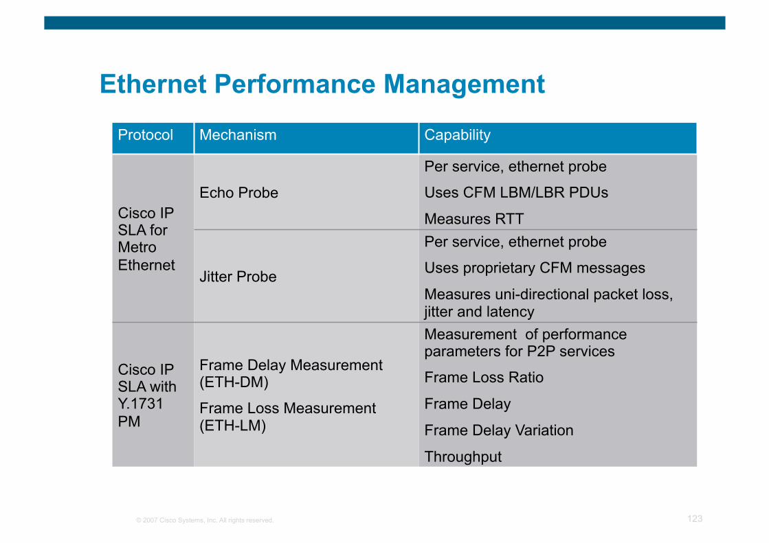
Ethernet Performance Management
Protocol Mechanism Capability
Cisco IP SLA for Metro Ethernet
Echo Probe
Per service, ethernet probe
Uses CFM LBM/LBR PDUs
Measures RTT
Jitter Probe
Per service, ethernet probe
Uses proprietary CFM messages
Measures uni-directional packet loss, jitter and latency
Cisco IP SLA with Y.1731 PM
Frame Delay Measurement (ETH-DM)
Frame Loss Measurement (ETH-LM)
Measurement of performance parameters for P2P services
Frame Loss Ratio
Frame Delay
Frame Delay Variation
Throughput
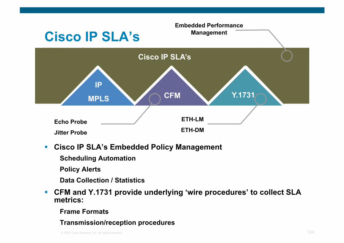
© 2007 Cisco Systems, Inc. All rights reserved. 124
Cisco IP SLA’s Cisco IP SLA’s
CFM Y.1731 IP
MPLS
Echo Probe
Jitter Probe
ETH-LM
ETH-DM
Embedded Performance Management
Cisco IP SLA’s Embedded Policy Management Scheduling Automation Policy Alerts Data Collection / Statistics
CFM and Y.1731 provide underlying ‘wire procedures’ to collect SLA metrics:
Frame Formats Transmission/reception procedures
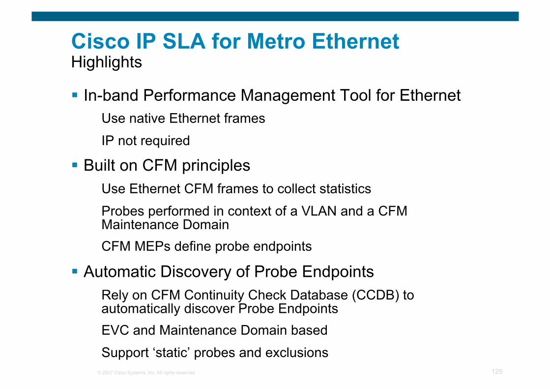
© 2007 Cisco Systems, Inc. All rights reserved. 125
In-band Performance Management Tool for Ethernet Use native Ethernet frames IP not required
Built on CFM principles Use Ethernet CFM frames to collect statistics Probes performed in context of a VLAN and a CFM Maintenance Domain CFM MEPs define probe endpoints
Automatic Discovery of Probe Endpoints Rely on CFM Continuity Check Database (CCDB) to automatically discover Probe Endpoints EVC and Maintenance Domain based Support ‘static’ probes and exclusions
Cisco IP SLA for Metro Ethernet Highlights

© 2007 Cisco Systems, Inc. All rights reserved. 126
Ethernet OAM and Fault Management
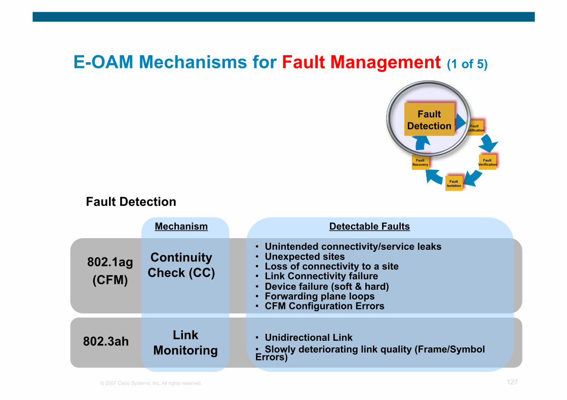
© 2007 Cisco Systems, Inc. All rights reserved. 127
E-OAM Mechanisms for Fault Management (1 of 5)
Fault Detection
802.1ag (CFM)
802.3ah
Continuity Check (CC)
Link Monitoring
Mechanism Detectable Faults
• Unintended connectivity/service leaks • Unexpected sites • Loss of connectivity to a site • Link Connectivity failure • Device failure (soft & hard) • Forwarding plane loops • CFM Configuration Errors
• Unidirectional Link • Slowly deteriorating link quality (Frame/Symbol Errors)
Fault Notification
Fault Recovery
Fault Detection
Fault Verification
Fault Isolation
Fault Detection
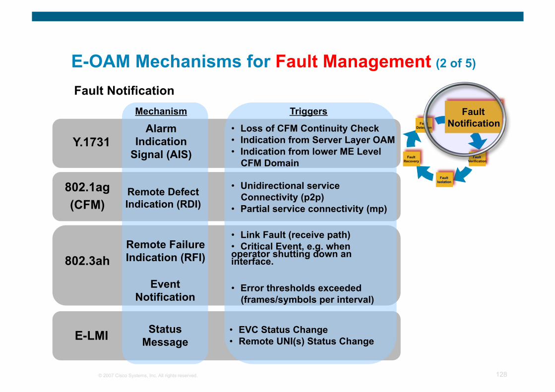
© 2007 Cisco Systems, Inc. All rights reserved. 128
E-OAM Mechanisms for Fault Management (2 of 5)
Fault Notification
Fault Recovery
Fault Detection
Fault Verification
Fault Isolation
Fault Notification
Fault Notification
Y.1731
802.3ah
802.1ag (CFM)
Alarm Indication
Signal (AIS)
Remote Failure Indication (RFI)
Remote Defect Indication (RDI)
Mechanism
• Link Fault (receive path) • Critical Event, e.g. when operator shutting down an interface.
Event Notification
• Error thresholds exceeded (frames/symbols per interval)
Triggers
• Loss of CFM Continuity Check • Indication from Server Layer OAM • Indication from lower ME Level
CFM Domain
• Unidirectional service Connectivity (p2p)
• Partial service connectivity (mp)
E-LMI Status Message
• EVC Status Change • Remote UNI(s) Status Change
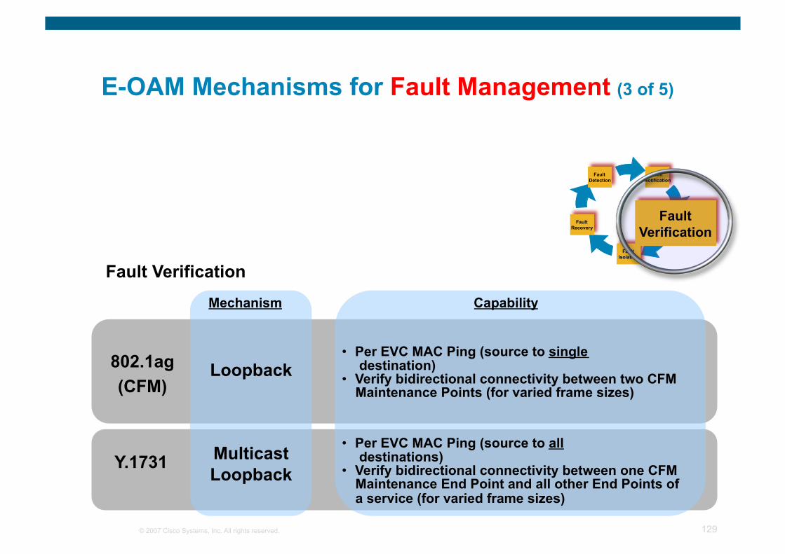
© 2007 Cisco Systems, Inc. All rights reserved. 129
E-OAM Mechanisms for Fault Management (3 of 5)
Fault Notification
Fault Recovery
Fault Detection
Fault Verification
Fault Isolation
Fault Verification
Fault Verification
802.1ag (CFM)
Y.1731
Loopback
Multicast Loopback
Mechanism Capability
• Per EVC MAC Ping (source to single destination)
• Verify bidirectional connectivity between two CFM Maintenance Points (for varied frame sizes)
• Per EVC MAC Ping (source to all destinations)
• Verify bidirectional connectivity between one CFM Maintenance End Point and all other End Points of a service (for varied frame sizes)

© 2007 Cisco Systems, Inc. All rights reserved. 130
E-OAM Mechanisms for Fault Management (4 of 5)
Fault Notification
Fault Recovery
Fault Detection
Fault Verification
Fault Isolation
Fault Isolation
Fault Isolation
802.1ag (CFM) Link Trace
Mechanism Capability
• Per EVC MAC Traceroute • Discover Maintenance Intermediate Points on path
from source End Point to destination End Point • Report Ingress Action, Relay Action, Egress
Action hop by hop. • Report encountered ACLs or STP-blocked ports
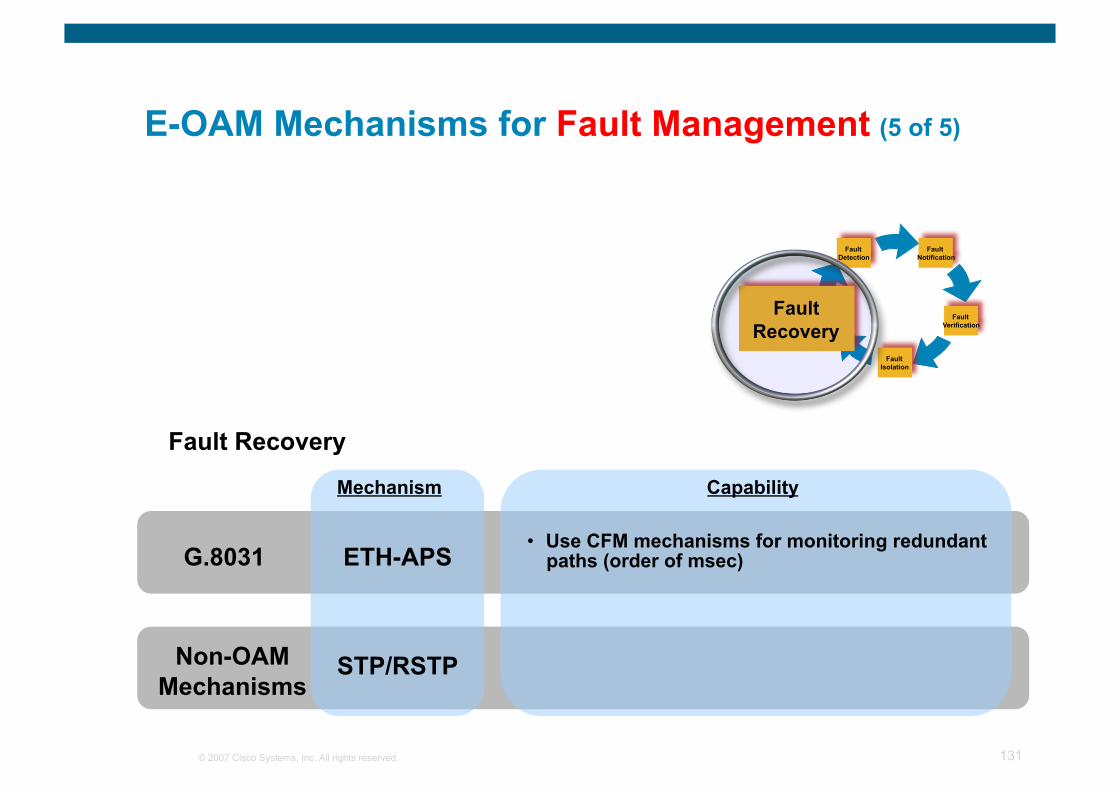
© 2007 Cisco Systems, Inc. All rights reserved. 131
E-OAM Mechanisms for Fault Management (5 of 5)
Fault Notification
Fault Recovery
Fault Detection
Fault Verification
Fault Isolation
Fault Recovery
Fault Recovery
ETH-APS
Mechanism Capability
• Use CFM mechanisms for monitoring redundant paths (order of msec) G.8031
Non-OAM Mechanisms
STP/RSTP
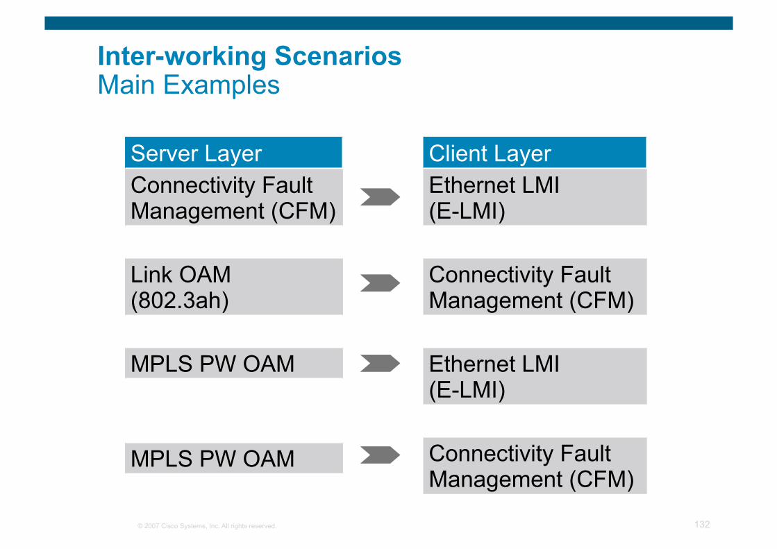
© 2007 Cisco Systems, Inc. All rights reserved. 132
Inter-working Scenarios Main Examples
Server Layer Connectivity Fault Management (CFM)
Link OAM (802.3ah)
MPLS PW OAM
MPLS PW OAM
Client Layer Ethernet LMI (E-LMI)
Connectivity Fault Management (CFM)
Ethernet LMI (E-LMI)
Connectivity Fault Management (CFM)
© 2007 Cisco Systems, Inc. All rights reserved. 133
Ethernet OAM Fault Management Scenarios
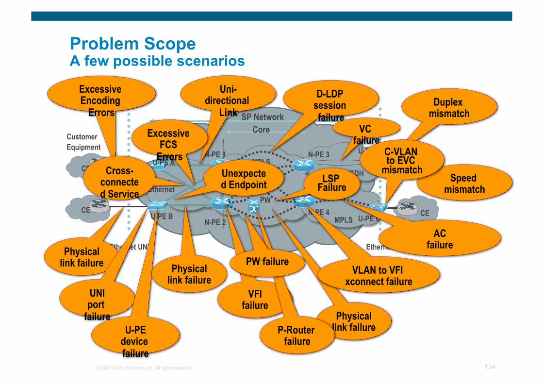
© 2007 Cisco Systems, Inc. All rights reserved. 134
Problem Scope A few possible scenarios
U-PE A
U-PE B U-PE C
N-PE 3
N-PE 4 N-PE 2
N-PE 1
Customer Equipment
CE
CE CE
Ethernet UNI
SP Network
PW
Access Core
CE
U-PE D
Ethernet UNI
MPLS
MPLS SONET/SDH
Native Ethernet
Physical link failure
UNI port
failure U-PE
device failure
Physical link failure
VFI failure
Physical link failure P-Router
failure
PW failure VLAN to VFI
xconnect failure
Duplex mismatch
Speed mismatch
D-LDP session failure
VC failure
AC failure
Uni-directional
Link
Excessive Encoding
Errors
Excessive FCS
Errors Cross-
connected Service
Unexpected Endpoint LSP
Failure
C-VLAN to EVC
mismatch
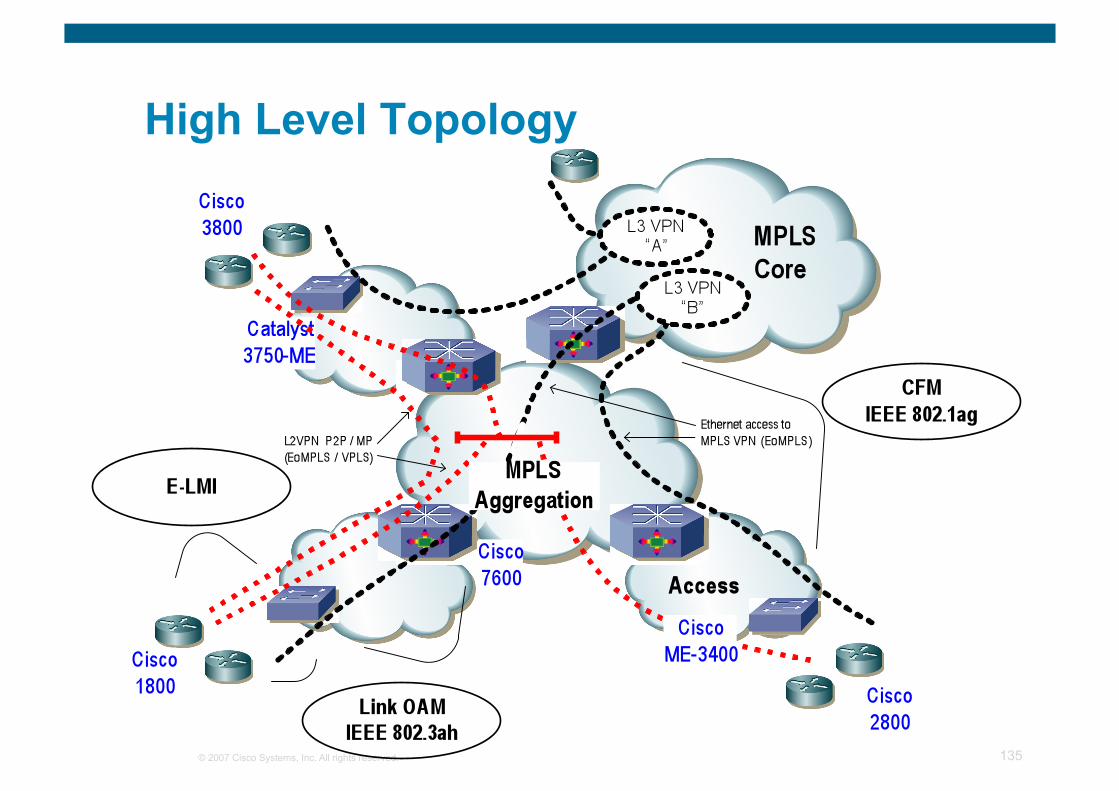
© 2007 Cisco Systems, Inc. All rights reserved. 135
High Level Topology
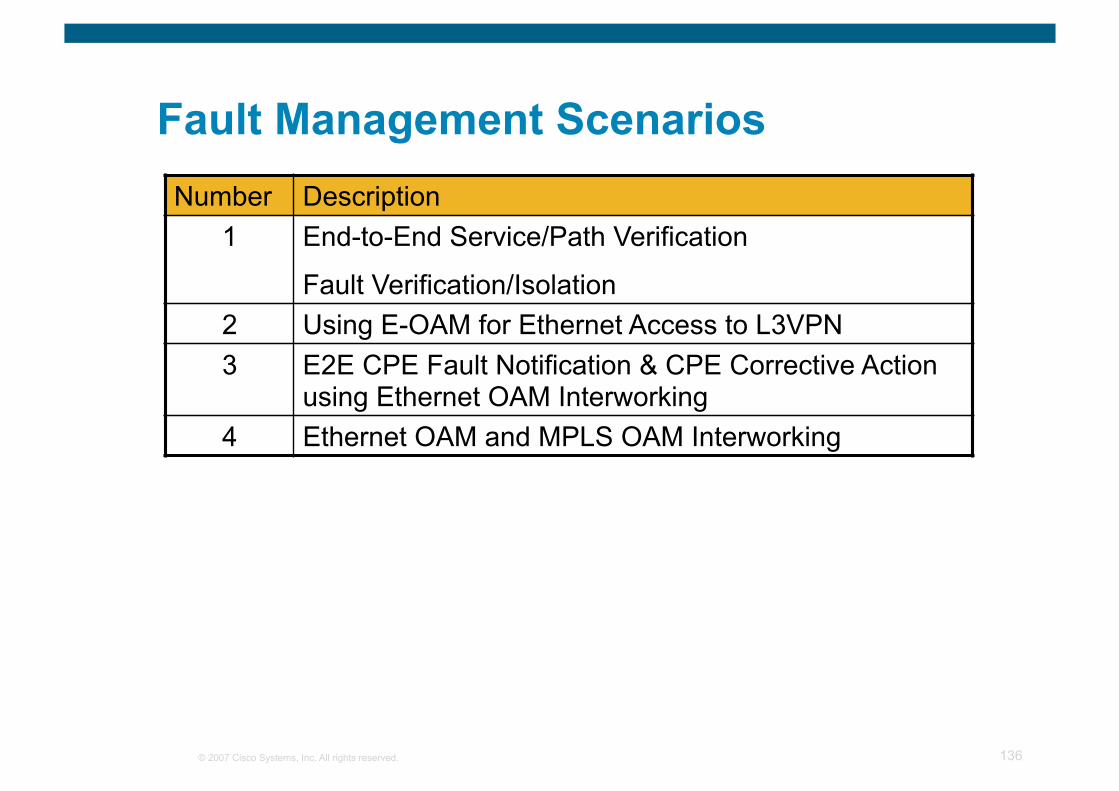
© 2007 Cisco Systems, Inc. All rights reserved. 136
Fault Management Scenarios Number Description
1 End-to-End Service/Path Verification
Fault Verification/Isolation 2 Using E-OAM for Ethernet Access to L3VPN 3 E2E CPE Fault Notification & CPE Corrective Action
using Ethernet OAM Interworking 4 Ethernet OAM and MPLS OAM Interworking
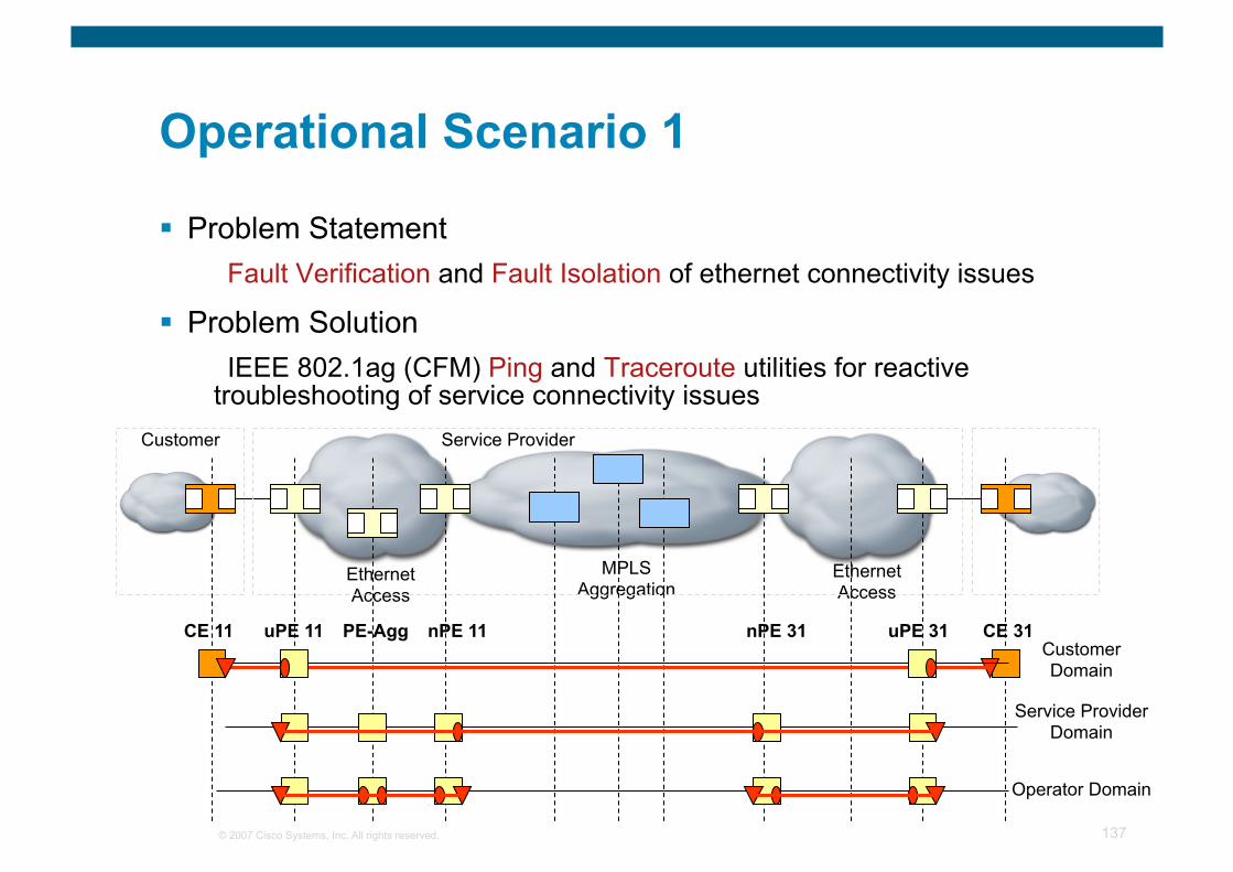
© 2007 Cisco Systems, Inc. All rights reserved. 137
Operational Scenario 1
Problem Statement Fault Verification and Fault Isolation of ethernet connectivity issues
Problem Solution IEEE 802.1ag (CFM) Ping and Traceroute utilities for reactive
troubleshooting of service connectivity issues
Ethernet Access
MPLS Aggregation Ethernet
Access
Customer Service Provider
Customer Domain
Service Provider Domain
Operator Domain
CE 11 CE 31 uPE 31 nPE 31 nPE 11 uPE 11 PE-Agg
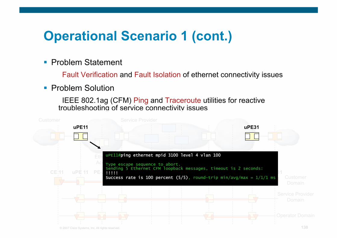
© 2007 Cisco Systems, Inc. All rights reserved. 138
Operational Scenario 1 (cont.)
Problem Statement Fault Verification and Fault Isolation of ethernet connectivity issues
Problem Solution IEEE 802.1ag (CFM) Ping and Traceroute utilities for reactive
troubleshooting of service connectivity issues
Ethernet Access
MPLS Core Ethernet Access
Customer Service Provider
Customer Domain
Service Provider Domain
Operator Domain
CE 11 CE 31 uPE 31 nPE 31 nPE 11 uPE 11 PE-Agg
uPE11#ping ethernet mpid 3100 level 4 vlan 100
Type escape sequence to abort. Sending 5 Ethernet CFM loopback messages, timeout is 2 seconds: !!!!! Success rate is 100 percent (5/5), round-trip min/avg/max = 1/1/1 ms
uPE11 uPE31
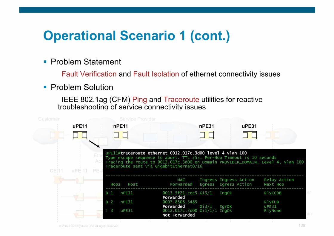
© 2007 Cisco Systems, Inc. All rights reserved. 139
Operational Scenario 1 (cont.)
Problem Statement Fault Verification and Fault Isolation of ethernet connectivity issues
Problem Solution IEEE 802.1ag (CFM) Ping and Traceroute utilities for reactive
troubleshooting of service connectivity issues
Ethernet Access
MPLS Core Ethernet Access
Customer Service Provider
Customer Domain
Service Provider Domain
Operator Domain
CE 11 CE 31 uPE 31 nPE 31 nPE 11 uPE 11 PE-Agg
uPE11#traceroute ethernet 0012.017c.3d00 level 4 vlan 100 Type escape sequence to abort. TTL 255. Per-Hop Timeout is 10 seconds Tracing the route to 0012.017c.3d00 on Domain PROVIDER_DOMAIN, Level 4, vlan 100 Traceroute sent via GigabitEthernet0/16
-------------------------------------------------------------------------------- MAC Ingress Ingress Action Relay Action Hops Host Forwarded Egress Egress Action Next Hop -------------------------------------------------------------------------------- B 1 nPE11 0013.5f21.cec5 Gi3/1 IngOk RlyCCDB Forwarded B 2 nPE31 0007.8508.3485 RlyFDB Forwarded Gi3/1 EgrOK uPE31 ! 3 uPE31 0012.017c.3d00 Gi1/1/1 IngOk RlyNone Not Forwarded
uPE11 uPE31 nPE11 nPE31
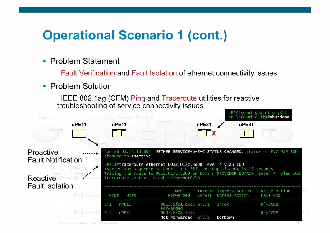
© 2007 Cisco Systems, Inc. All rights reserved. 140
Operational Scenario 1 (cont.)
Problem Statement Fault Verification and Fault Isolation of ethernet connectivity issues
Problem Solution IEEE 802.1ag (CFM) Ping and Traceroute utilities for reactive
troubleshooting of service connectivity issues
Ethernet Access
MPLS Core Ethernet Access
Customer Service Provider
Customer Domain
Service Provider Domain
Operator Domain
CE 11 CE 31 uPE 31 nPE 31 nPE 11 uPE 11 PE-Agg
Jan 26 03:14:10.608: %ETHER_SERVICE-6-EVC_STATUS_CHANGED: status of EVC_P2P_100 changed to InActive
uPE11#traceroute ethernet 0012.017c.3d00 level 4 vlan 100 Type escape sequence to abort. TTL 255. Per-Hop Timeout is 10 seconds Tracing the route to 0012.017c.3d00 on Domain PROVIDER_DOMAIN, Level 4, vlan 100 Traceroute sent via GigabitEthernet0/16
-------------------------------------------------------------------------------- MAC Ingress Ingress Action Relay Action Hops Host Forwarded Egress Egress Action Next Hop -------------------------------------------------------------------------------- B 1 nPE11 0013.5f21.cec5 Gi3/1 IngOk RlyCCDB Forwarded B 2 nPE31 0007.8508.3485 RlyCCDB Not Forwarded Gi3/1 EgrDown
nPE31(config)#int gig3/1 nPE31(config-if)#shutdown
X
Proactive Fault Notification
Reactive Fault Isolation
uPE11 uPE31 nPE11 nPE31
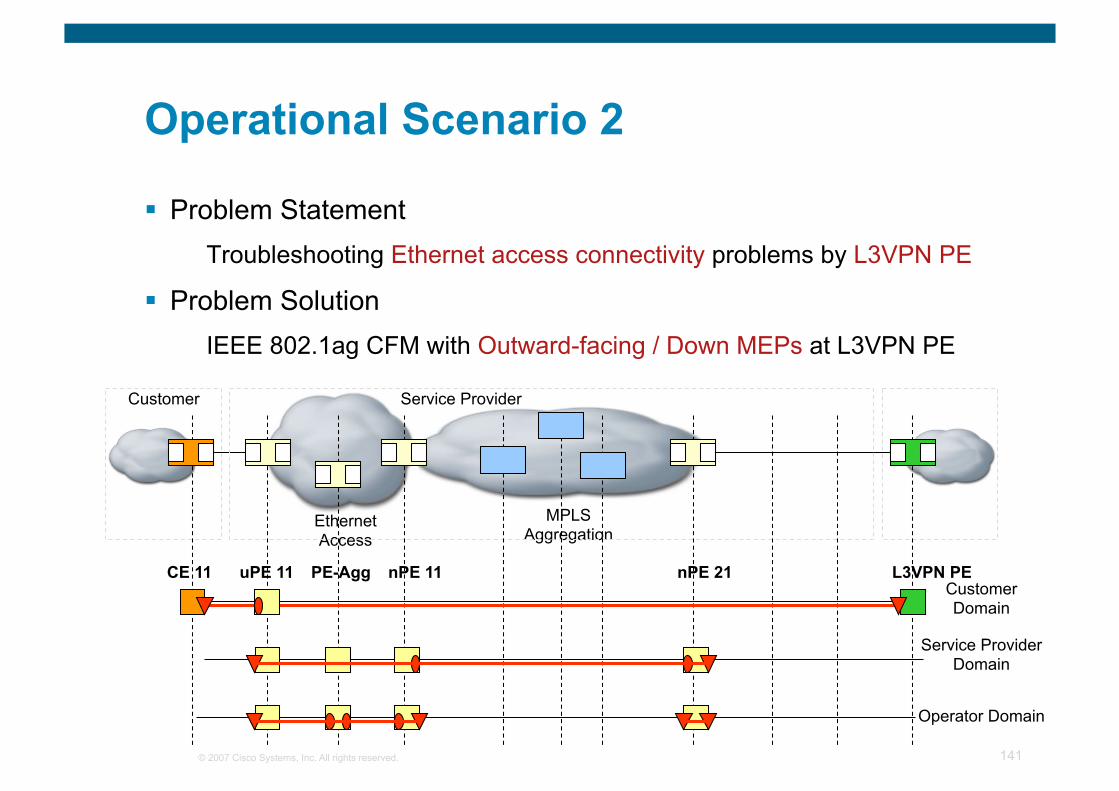
© 2007 Cisco Systems, Inc. All rights reserved. 141
Operational Scenario 2
Problem Statement Troubleshooting Ethernet access connectivity problems by L3VPN PE
Problem Solution IEEE 802.1ag CFM with Outward-facing / Down MEPs at L3VPN PE
MPLS Aggregation
Ethernet Access
Customer Service Provider
Customer Domain
Service Provider Domain
Operator Domain
CE 11 L3VPN PE nPE 21 nPE 11 uPE 11 PE-Agg
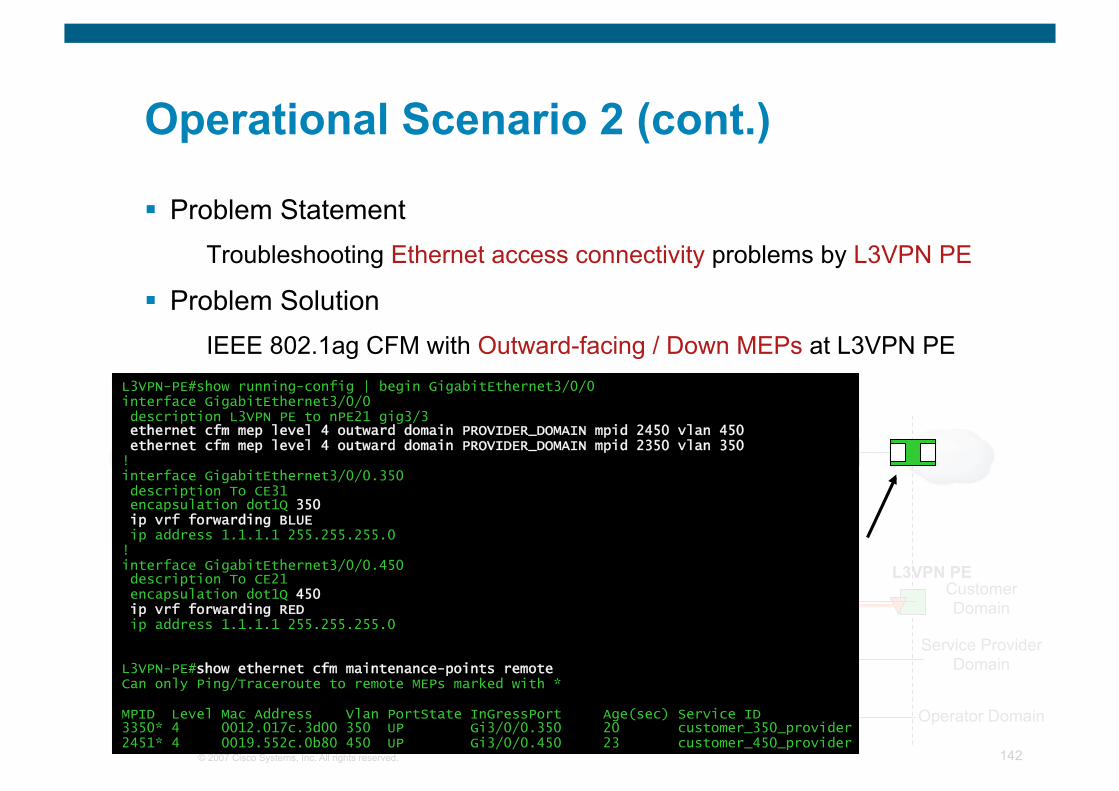
© 2007 Cisco Systems, Inc. All rights reserved. 142
Operational Scenario 2 (cont.)
Problem Statement Troubleshooting Ethernet access connectivity problems by L3VPN PE
Problem Solution IEEE 802.1ag CFM with Outward-facing / Down MEPs at L3VPN PE
Ethernet Access
MPLS Core Ethernet Access
Customer Service Provider
Customer Domain
Service Provider Domain
Operator Domain
CE 11 L3VPN PE uPE 21 nPE 21 nPE 11 uPE 11 PE-Agg
L3VPN-PE#show running-config | begin GigabitEthernet3/0/0 interface GigabitEthernet3/0/0 description L3VPN PE to nPE21 gig3/3 ethernet cfm mep level 4 outward domain PROVIDER_DOMAIN mpid 2450 vlan 450 ethernet cfm mep level 4 outward domain PROVIDER_DOMAIN mpid 2350 vlan 350 ! interface GigabitEthernet3/0/0.350 description To CE31 encapsulation dot1Q 350 ip vrf forwarding BLUE ip address 1.1.1.1 255.255.255.0 ! interface GigabitEthernet3/0/0.450 description To CE21 encapsulation dot1Q 450 ip vrf forwarding RED ip address 1.1.1.1 255.255.255.0
L3VPN-PE#show ethernet cfm maintenance-points remote Can only Ping/Traceroute to remote MEPs marked with *
MPID Level Mac Address Vlan PortState InGressPort Age(sec) Service ID 3350* 4 0012.017c.3d00 350 UP Gi3/0/0.350 20 customer_350_provider 2451* 4 0019.552c.0b80 450 UP Gi3/0/0.450 23 customer_450_provider
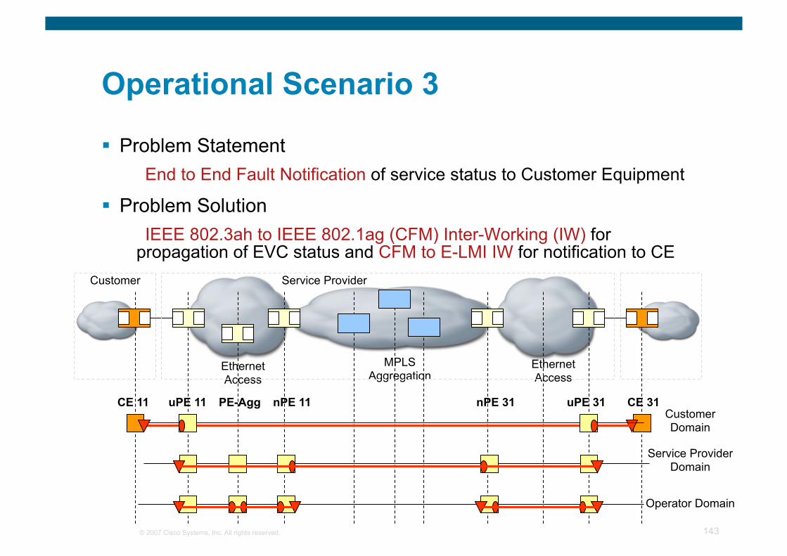
© 2007 Cisco Systems, Inc. All rights reserved. 143
Operational Scenario 3
Problem Statement End to End Fault Notification of service status to Customer Equipment
Problem Solution IEEE 802.3ah to IEEE 802.1ag (CFM) Inter-Working (IW) for
propagation of EVC status and CFM to E-LMI IW for notification to CE
Ethernet Access
MPLS Aggregation
Ethernet Access
Customer Service Provider
Customer Domain
Service Provider Domain
Operator Domain
CE 11 CE 31 uPE 31 nPE 31 nPE 11 uPE 11 PE-Agg
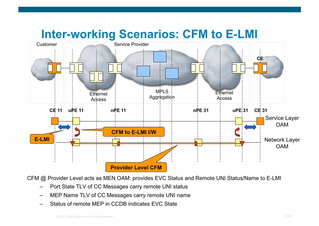
© 2007 Cisco Systems, Inc. All rights reserved. 144
Inter-working Scenarios: CFM to E-LMI
CFM @ Provider Level acts as MEN OAM: provides EVC Status and Remote UNI Status/Name to E-LMI – Port State TLV of CC Messages carry remote UNI status – MEP Name TLV of CC Messages carry remote UNI name – Status of remote MEP in CCDB indicates EVC State
CE 11
CE
Ethernet Access
MPLS Aggregation
Ethernet Access
Service Layer OAM
Network Layer OAM
E-LMI
CE 31 uPE 31 nPE 31 nPE 11 uPE 11
Provider Level CFM
CFM to E-LMI I/W
Customer Service Provider
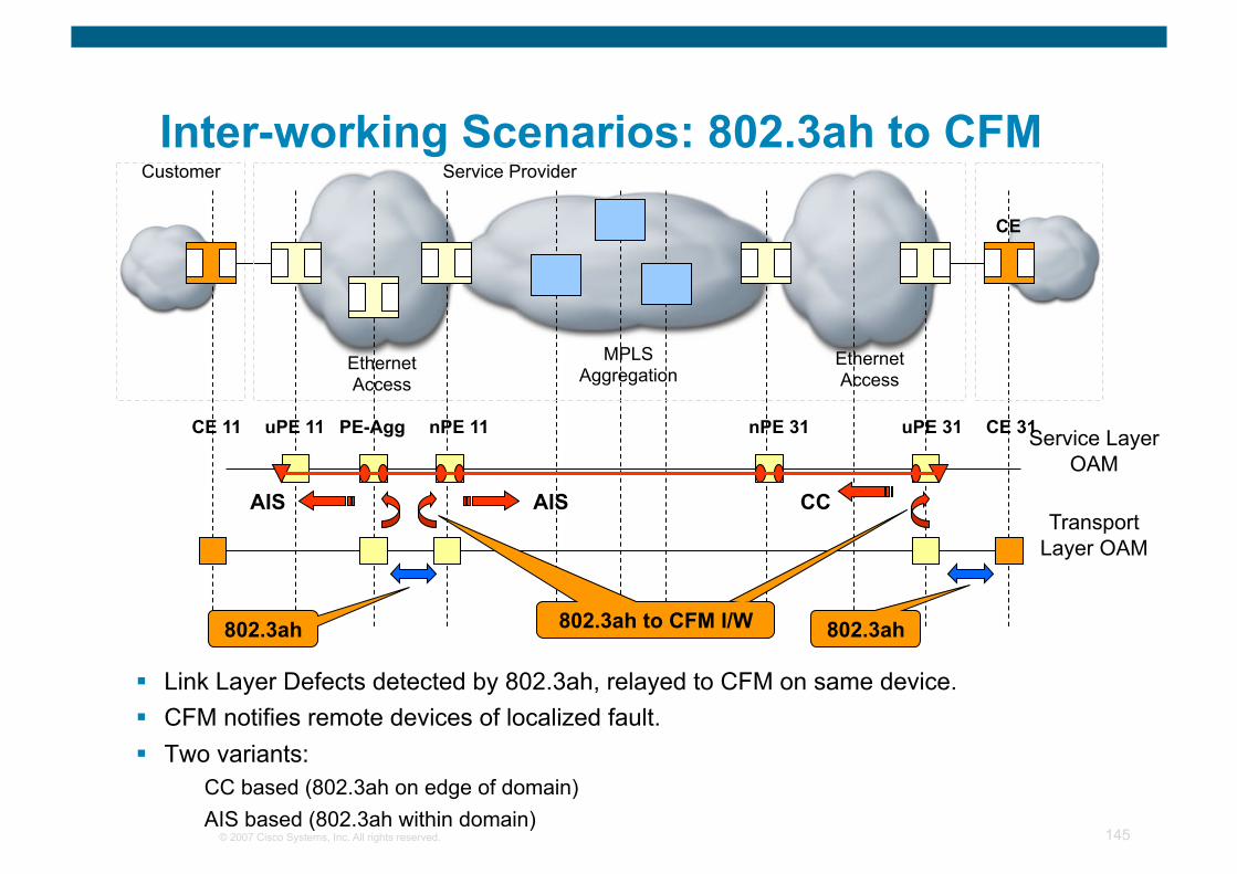
© 2007 Cisco Systems, Inc. All rights reserved. 145
Link Layer Defects detected by 802.3ah, relayed to CFM on same device. CFM notifies remote devices of localized fault. Two variants:
CC based (802.3ah on edge of domain) AIS based (802.3ah within domain)
CE 11
CE
Ethernet Access
MPLS Aggregation
Ethernet Access
Service Layer OAM
Transport Layer OAM
802.3ah
CE 31 uPE 31 nPE 31 nPE 11 uPE 11
Customer Service Provider
PE-Agg
802.3ah 802.3ah to CFM I/W
CC AIS AIS
Inter-working Scenarios: 802.3ah to CFM
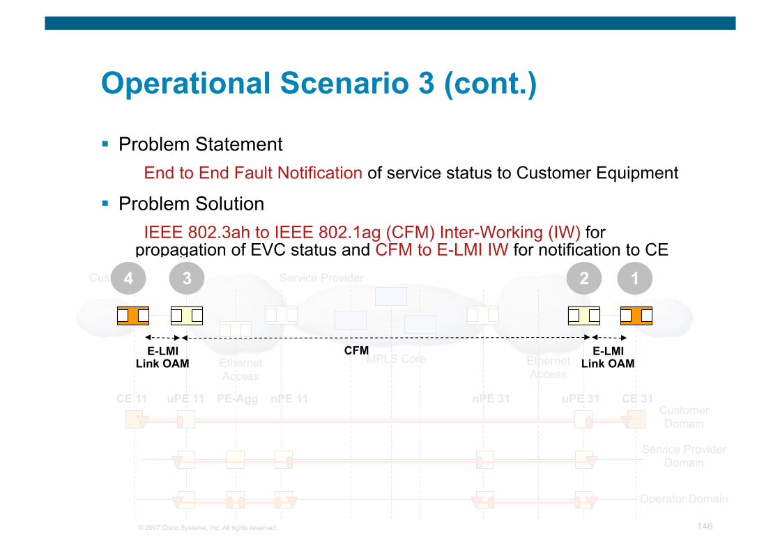
© 2007 Cisco Systems, Inc. All rights reserved. 146
Operational Scenario 3 (cont.)
Problem Statement End to End Fault Notification of service status to Customer Equipment
Problem Solution IEEE 802.3ah to IEEE 802.1ag (CFM) Inter-Working (IW) for
propagation of EVC status and CFM to E-LMI IW for notification to CE
Ethernet Access
MPLS Core Ethernet Access
Customer Service Provider
Customer Domain
Service Provider Domain
Operator Domain
CE 11 CE 31 uPE 31 nPE 31 nPE 11 uPE 11 PE-Agg
1 4 3 2
CFM E-LMI Link OAM
E-LMI Link OAM
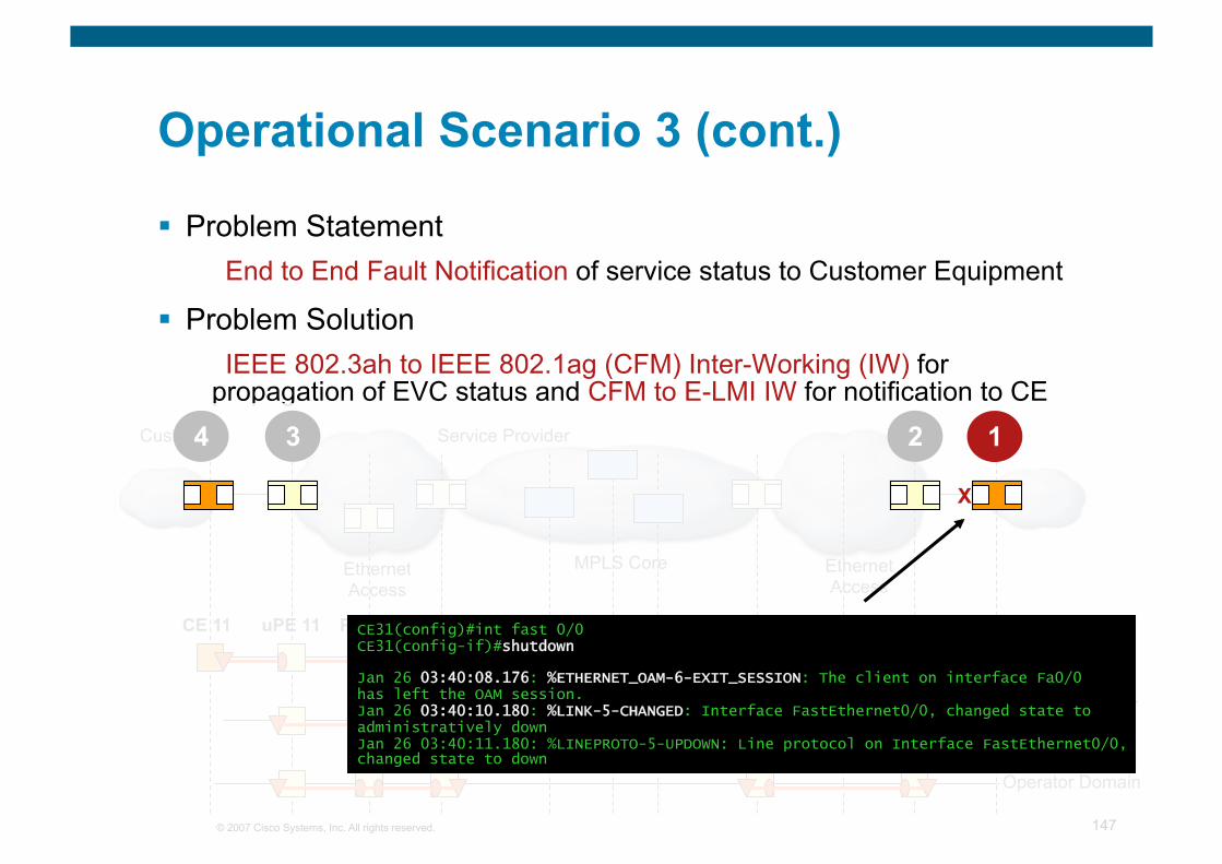
© 2007 Cisco Systems, Inc. All rights reserved. 147
Operational Scenario 3 (cont.)
Problem Statement End to End Fault Notification of service status to Customer Equipment
Problem Solution IEEE 802.3ah to IEEE 802.1ag (CFM) Inter-Working (IW) for
propagation of EVC status and CFM to E-LMI IW for notification to CE
Ethernet Access
MPLS Core Ethernet Access
Customer Service Provider
Customer Domain
Service Provider Domain
Operator Domain
CE 11 CE 31 uPE 31 nPE 31 nPE 11 uPE 11 PE-Agg CE31(config)#int fast 0/0 CE31(config-if)#shutdown
Jan 26 03:40:08.176: %ETHERNET_OAM-6-EXIT_SESSION: The client on interface Fa0/0 has left the OAM session. Jan 26 03:40:10.180: %LINK-5-CHANGED: Interface FastEthernet0/0, changed state to administratively down Jan 26 03:40:11.180: %LINEPROTO-5-UPDOWN: Line protocol on Interface FastEthernet0/0, changed state to down
X
1 4 3 2
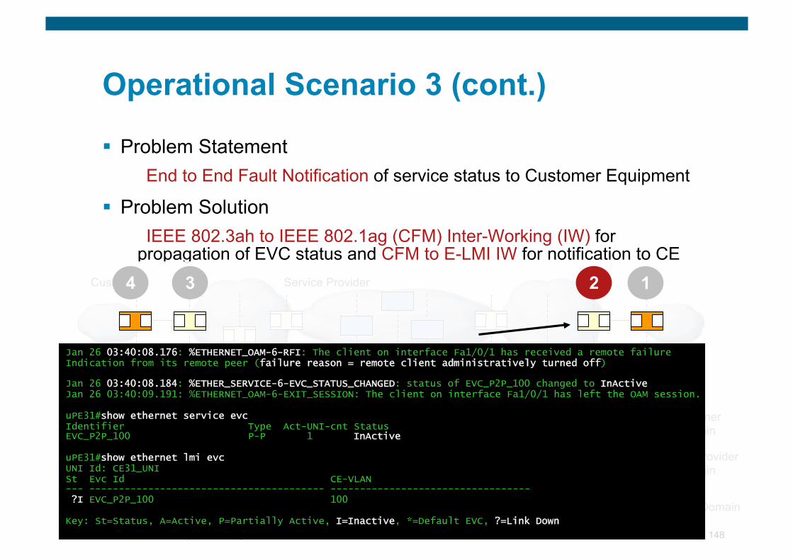
© 2007 Cisco Systems, Inc. All rights reserved. 148
Operational Scenario 3 (cont.)
Problem Statement End to End Fault Notification of service status to Customer Equipment
Problem Solution IEEE 802.3ah to IEEE 802.1ag (CFM) Inter-Working (IW) for
propagation of EVC status and CFM to E-LMI IW for notification to CE
Ethernet Access
MPLS Core Ethernet Access
Customer Service Provider
Customer Domain
Service Provider Domain
Operator Domain
CE 11 CE 31 uPE 31 nPE 31 nPE 11 uPE 11 PE-Agg
Jan 26 03:40:08.176: %ETHERNET_OAM-6-RFI: The client on interface Fa1/0/1 has received a remote failure Indication from its remote peer (failure reason = remote client administratively turned off)
Jan 26 03:40:08.184: %ETHER_SERVICE-6-EVC_STATUS_CHANGED: status of EVC_P2P_100 changed to InActive Jan 26 03:40:09.191: %ETHERNET_OAM-6-EXIT_SESSION: The client on interface Fa1/0/1 has left the OAM session.
uPE31#show ethernet service evc Identifier Type Act-UNI-cnt Status EVC_P2P_100 P-P 1 InActive
uPE31#show ethernet lmi evc UNI Id: CE31_UNI St Evc Id CE-VLAN --- ---------------------------------------- ---------------------------------- ?I EVC_P2P_100 100
Key: St=Status, A=Active, P=Partially Active, I=Inactive, *=Default EVC, ?=Link Down
1 4 3 2
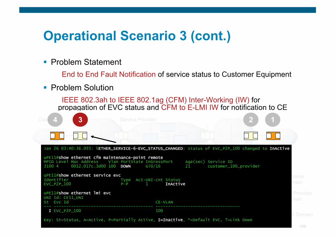
© 2007 Cisco Systems, Inc. All rights reserved. 149
Operational Scenario 3 (cont.)
Problem Statement End to End Fault Notification of service status to Customer Equipment
Problem Solution IEEE 802.3ah to IEEE 802.1ag (CFM) Inter-Working (IW) for
propagation of EVC status and CFM to E-LMI IW for notification to CE
Ethernet Access
MPLS Core Ethernet Access
Customer Service Provider
Customer Domain
Service Provider Domain
Operator Domain
CE 11 CE 31 uPE 31 nPE 31 nPE 11 uPE 11 PE-Agg
1 4 3 2
Jan 26 03:40:36.093: %ETHER_SERVICE-6-EVC_STATUS_CHANGED: status of EVC_P2P_100 changed to InActive
uPE11#show ethernet cfm maintenance-point remote MPID Level Mac Address Vlan PortState InGressPort Age(sec) Service ID 3100 4 0012.017c.3d00 100 DOWN Gi0/16 21 customer_100_provider
uPE11#show ethernet service evc Identifier Type Act-UNI-cnt Status EVC_P2P_100 P-P 1 InActive
uPE11#show ethernet lmi evc UNI Id: CE11_UNI St Evc Id CE-VLAN --- ---------------------------------------- ---------------------------------- I EVC_P2P_100 100
Key: St=Status, A=Active, P=Partially Active, I=Inactive, *=Default EVC, ?=Link Down
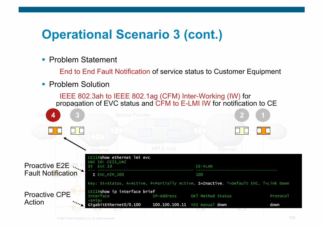
© 2007 Cisco Systems, Inc. All rights reserved. 150
Operational Scenario 3 (cont.)
Problem Statement End to End Fault Notification of service status to Customer Equipment
Problem Solution IEEE 802.3ah to IEEE 802.1ag (CFM) Inter-Working (IW) for
propagation of EVC status and CFM to E-LMI IW for notification to CE
Ethernet Access
MPLS Core Ethernet Access
Customer Service Provider
Customer Domain
Service Provider Domain
Operator Domain
CE 11 CE 31 uPE 31 nPE 31 nPE 11 uPE 11 PE-Agg
1 4 3 2
CE11#show ethernet lmi evc UNI Id: CE11_UNI St Evc Id CE-VLAN --- ---------------------------------------- ---------------------------------- I EVC_P2P_100 100
Key: St=Status, A=Active, P=Partially Active, I=Inactive, *=Default EVC, ?=Link Down
CE11#show ip interface brief Interface IP-Address OK? Method Status Protocol <snip> GigabitEthernet0/0.100 100.100.100.11 YES manual down down
Proactive E2E Fault Notification
Proactive CPE Action
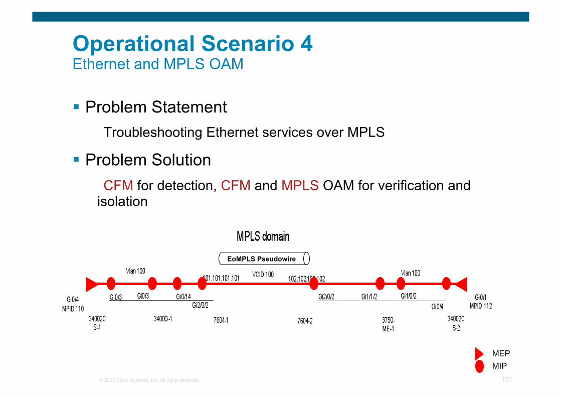
© 2007 Cisco Systems, Inc. All rights reserved. 151
Problem Statement Troubleshooting Ethernet services over MPLS
Problem Solution CFM for detection, CFM and MPLS OAM for verification and
isolation
Operational Scenario 4 Ethernet and MPLS OAM
EoMPLS Pseudowire
MEP MIP
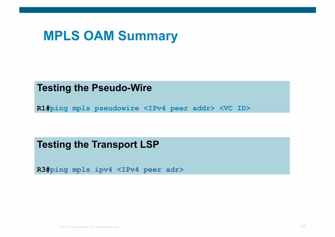
© 2007 Cisco Systems, Inc. All rights reserved. 152
MPLS OAM Summary
Testing the Pseudo-Wire
R1#ping mpls pseudowire <IPv4 peer addr> <VC ID>
Testing the Transport LSP
R3#ping mpls ipv4 <IPv4 peer adr>
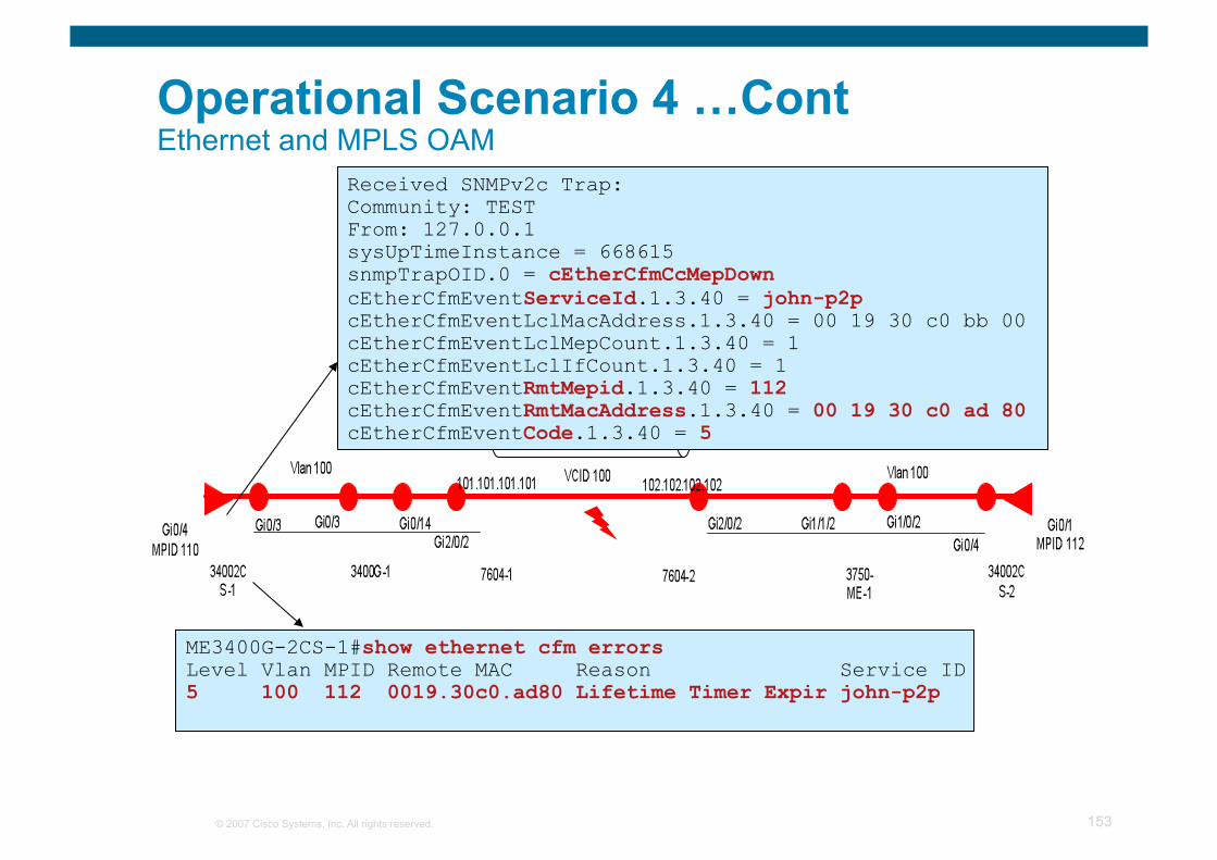
© 2007 Cisco Systems, Inc. All rights reserved. 153
ME3400G-2CS-1#show ethernet cfm errors Level Vlan MPID Remote MAC Reason Service ID 5 100 112 0019.30c0.ad80 Lifetime Timer Expir john-p2p
Operational Scenario 4 …Cont Ethernet and MPLS OAM
EoMPLS Pseudowire
Received SNMPv2c Trap: Community: TEST From: 127.0.0.1 sysUpTimeInstance = 668615 snmpTrapOID.0 = cEtherCfmCcMepDown cEtherCfmEventServiceId.1.3.40 = john-p2p cEtherCfmEventLclMacAddress.1.3.40 = 00 19 30 c0 bb 00 cEtherCfmEventLclMepCount.1.3.40 = 1 cEtherCfmEventLclIfCount.1.3.40 = 1 cEtherCfmEventRmtMepid.1.3.40 = 112 cEtherCfmEventRmtMacAddress.1.3.40 = 00 19 30 c0 ad 80 cEtherCfmEventCode.1.3.40 = 5
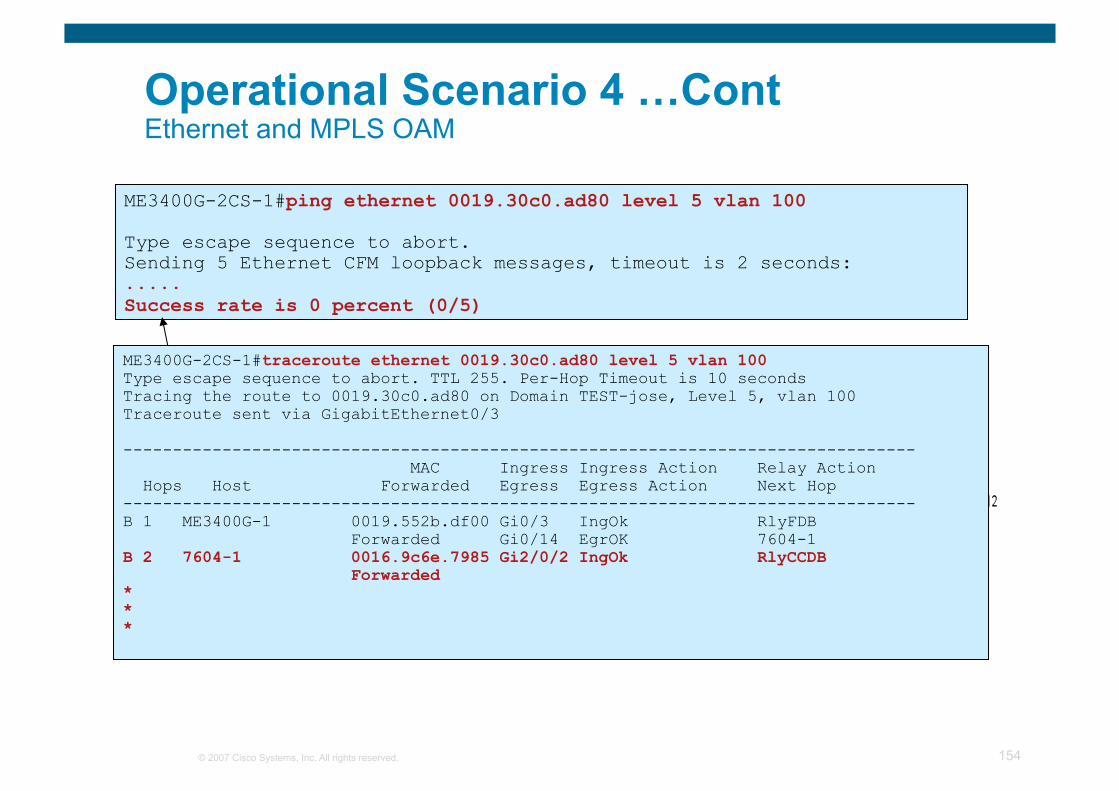
© 2007 Cisco Systems, Inc. All rights reserved. 154
ME3400G-2CS-1#ping ethernet 0019.30c0.ad80 level 5 vlan 100
Type escape sequence to abort. Sending 5 Ethernet CFM loopback messages, timeout is 2 seconds: ..... Success rate is 0 percent (0/5)
Operational Scenario 4 …Cont Ethernet and MPLS OAM
EoMPLS Pseudowire
ME3400G-2CS-1#traceroute ethernet 0019.30c0.ad80 level 5 vlan 100 Type escape sequence to abort. TTL 255. Per-Hop Timeout is 10 seconds Tracing the route to 0019.30c0.ad80 on Domain TEST-jose, Level 5, vlan 100 Traceroute sent via GigabitEthernet0/3
-------------------------------------------------------------------------------- MAC Ingress Ingress Action Relay Action Hops Host Forwarded Egress Egress Action Next Hop -------------------------------------------------------------------------------- B 1 ME3400G-1 0019.552b.df00 Gi0/3 IngOk RlyFDB Forwarded Gi0/14 EgrOK 7604-1 B 2 7604-1 0016.9c6e.7985 Gi2/0/2 IngOk RlyCCDB Forwarded * * *
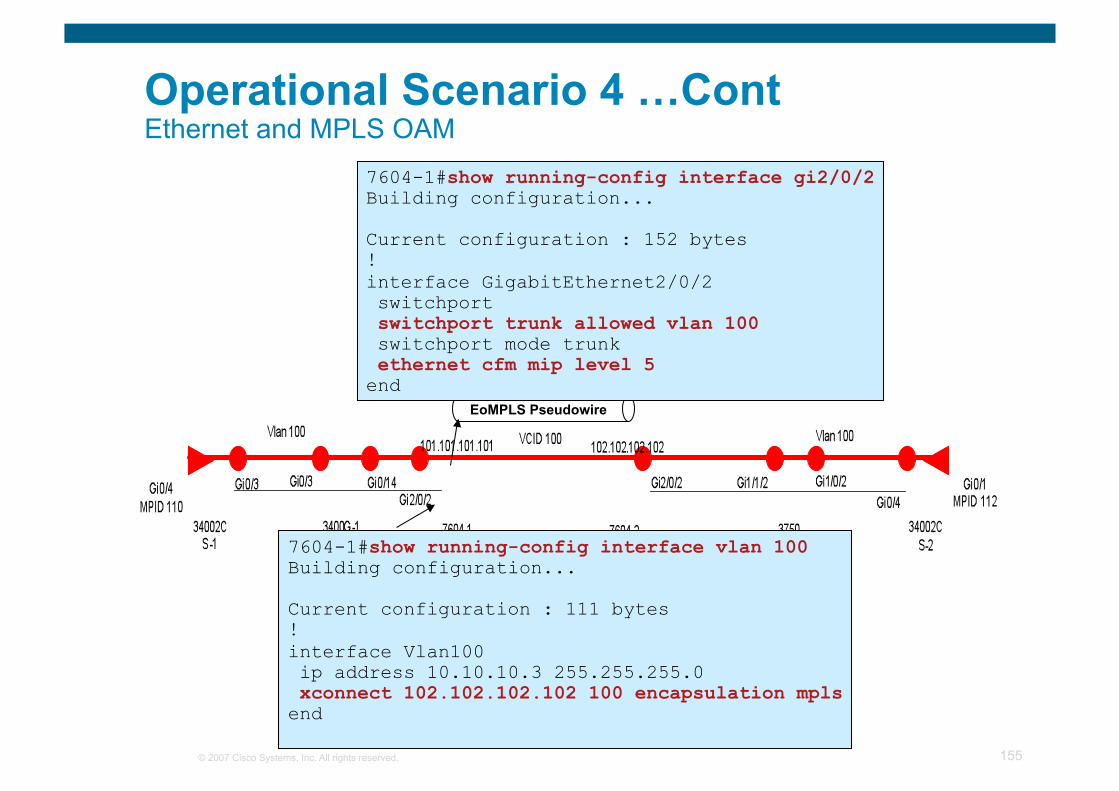
© 2007 Cisco Systems, Inc. All rights reserved. 155
Operational Scenario 4 …Cont Ethernet and MPLS OAM
EoMPLS Pseudowire
7604-1#show running-config interface vlan 100 Building configuration...
Current configuration : 111 bytes ! interface Vlan100 ip address 10.10.10.3 255.255.255.0 xconnect 102.102.102.102 100 encapsulation mpls end
7604-1#show running-config interface gi2/0/2 Building configuration...
Current configuration : 152 bytes ! interface GigabitEthernet2/0/2 switchport switchport trunk allowed vlan 100 switchport mode trunk ethernet cfm mip level 5 end
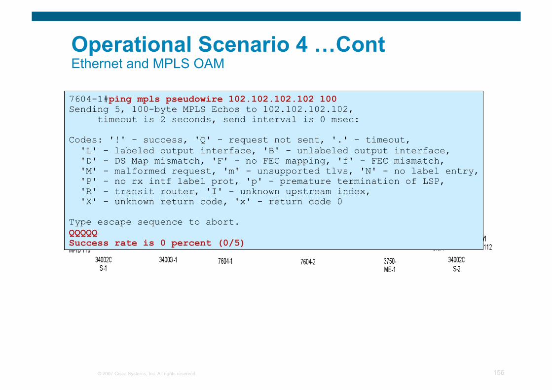
© 2007 Cisco Systems, Inc. All rights reserved. 156
Operational Scenario 4 …Cont Ethernet and MPLS OAM
EoMPLS Pseudowire
7604-1#ping mpls pseudowire 102.102.102.102 100 Sending 5, 100-byte MPLS Echos to 102.102.102.102, timeout is 2 seconds, send interval is 0 msec:
Codes: '!' - success, 'Q' - request not sent, '.' - timeout, 'L' - labeled output interface, 'B' - unlabeled output interface, 'D' - DS Map mismatch, 'F' - no FEC mapping, 'f' - FEC mismatch, 'M' - malformed request, 'm' - unsupported tlvs, 'N' - no label entry, 'P' - no rx intf label prot, 'p' - premature termination of LSP, 'R' - transit router, 'I' - unknown upstream index, 'X' - unknown return code, 'x' - return code 0
Type escape sequence to abort. QQQQQ Success rate is 0 percent (0/5)
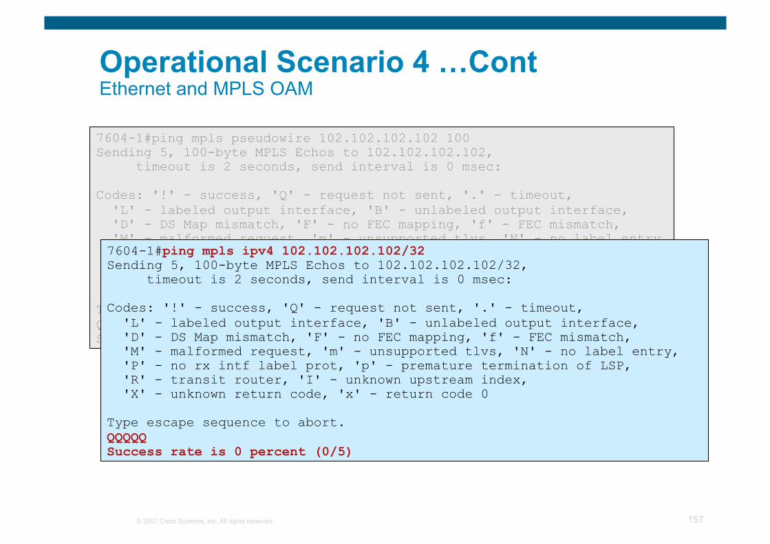
© 2007 Cisco Systems, Inc. All rights reserved. 157
7604-1#ping mpls pseudowire 102.102.102.102 100 Sending 5, 100-byte MPLS Echos to 102.102.102.102, timeout is 2 seconds, send interval is 0 msec:
Codes: '!' - success, 'Q' - request not sent, '.' - timeout, 'L' - labeled output interface, 'B' - unlabeled output interface, 'D' - DS Map mismatch, 'F' - no FEC mapping, 'f' - FEC mismatch, 'M' - malformed request, 'm' - unsupported tlvs, 'N' - no label entry, 'P' - no rx intf label prot, 'p' - premature termination of LSP, 'R' - transit router, 'I' - unknown upstream index, 'X' - unknown return code, 'x' - return code 0
Type escape sequence to abort. QQQQQ Success rate is 0 percent (0/5)
7604-1#ping mpls ipv4 102.102.102.102/32 Sending 5, 100-byte MPLS Echos to 102.102.102.102/32, timeout is 2 seconds, send interval is 0 msec:
Codes: '!' - success, 'Q' - request not sent, '.' - timeout, 'L' - labeled output interface, 'B' - unlabeled output interface, 'D' - DS Map mismatch, 'F' - no FEC mapping, 'f' - FEC mismatch, 'M' - malformed request, 'm' - unsupported tlvs, 'N' - no label entry, 'P' - no rx intf label prot, 'p' - premature termination of LSP, 'R' - transit router, 'I' - unknown upstream index, 'X' - unknown return code, 'x' - return code 0
Type escape sequence to abort. QQQQQ Success rate is 0 percent (0/5)
Operational Scenario 4 …Cont Ethernet and MPLS OAM
© 2007 Cisco Systems, Inc. All rights reserved. 158
Summary
You have an understanding of Ethernet OAM Protocols including CFM, Link OAM (802.3ah), Y.1731 & E-LMI
You have the fundamental understanding of Ethernet OAM Interworking.
You have seen how Ethernet OAM and OAM Interworking can be used to handle some common fault scenario!

© 2007 Cisco Systems, Inc. All rights reserved. 159
Questions?
© 2007 Cisco Systems, Inc. All rights reserved. 160