carling switches and accessories - amelec australiaamelec.com.au/pdfs/carling switches...
TRANSCRIPT

July 2016 Edition
Standard InventoryProducts Guide
Carling Switches and Accessories
Amelec Australia Pty Ltd is pleased to introduce our new Carling Technologies ‘Standard Inventory Products Guide’ for switches July 2016 Edition.
This guide showcases a selection of the most popular switch offerings available off-the-shelf at Amelec Australia. It includes a range of Carling’s impressive Contura V and L-Series rocker switches which feature a patented roller mechanism design. These switches are the staple of the transport industry and are specified by original equipment manufacturers in the marine, automotive and heavy duty on/off road industry worldwide.
Although a generous cross section is presented in this guide, it is only a small portion of the huge range of switches available from Carling Technologies. There are literally thousands of different configurations available, including; interchangeable rocker actuator styles, sealed or unsealed variants, incandescent or LED illumination, voltage and current ratings and many, many more options.
Whatever the requirement, Carling Technologies extensive range of switches can meet almost any application.
Introduction
Cover photos of truck and tractor are courtesy of Wikimedia Commons. With thanks to Wouter Hagens and Dgolnik.
1
Contents
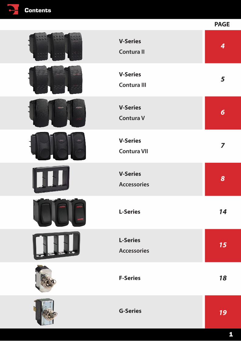
5
7
14
18
4
6
8
15
19G-Series
F-Series
L-Series
Accessories
L-Series
V-Series
Accessories
V-Series
Contura VII
V-Series
Contura V
V-Series
Contura III
V-Series
Contura II
PAGE
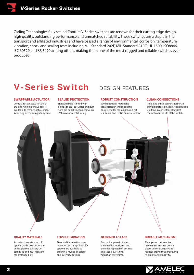
Silver plated butt-contact mechanism ensures greater electrical conductivity and reduces arcing thus improving reliability and longevity.
DURABLE MECHANISM
Brass roller pin eliminates the need for lubricants and provides repeatable, positive and tactile switching actuation every time.
DESIGNED TO LAST
Standard illumination uses incandescent lamps but LED options are available to order in a myriad of colour and intensity options.
LENS ILLUMINATION
Actuator is constructed of optical grade polycarbonate with Nylon 66 overlay, UV stabilised and heat resistant for prolonged life.
QUALITY MATERIALS
Tin plated quick-connect terminals provide protection against oxidisation resulting in consistent electrical contact over the life of the switch.
CLEAN CONNECTIONSSwitch housing material is constructed in thermoplastic polyester alloy for maximum heat resistance and is also �ame retardant.
ROBUST CONSTRUCTIONStandard base is �tted with o-rings to seal out water and dust from the panel side to achieve an IP68 environmental rating.
SEALED PROTECTIONContura rocker actuators are a snap �t. An inexpensive tool is available to remove actuators for swapping or replacing at any time.
SWAPPABLE ACTUATOR
V-Series Switch DESIGN FEATURES
Carling Technologies fully sealed Contura V-Series switches are renown for their cutting edge design, high quality, outstanding performance and unmatched reliability. These switches are a staple in the transport and a�liated industries and have passed a range of environmental, corrosion, temperature, vibration, shock and sealing tests including MIL Standard 202F, MIL Standard 810C, UL 1500, ISO8846, IEC 60529 and BS 5490 among others, making them one of the most rugged and reliable switches ever produced.
2
V-Series Rocker Switches
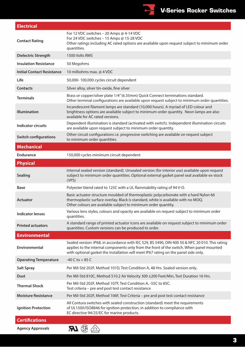
Electrical
Contact Rating
For 12 VDC switches – 20 Amps @ 4-14 VDC For 24 VDC switches – 15 Amps @ 15-28 VDCOther ratings including AC rated options are available upon request subject to minimum order quantities.
Dielectric Strength 1500 Volts RMS
Insulation Resistance 50 Megohms
Initial Contact Resistance 10 milliohms max. @ 4 VDC
Life 50,000- 100,000 cycles circuit dependent
Contacts
Terminals Brass or copper/silver plate 1/4” (6.35mm) Quick Connect terminations standard.
Illumination brightness options are available subject to minimum order quantity. Neon lamps are also available for AC rated versions.
Indicator circuits Dependent illumination is standard (activated with switch). Independent illumination circuits are available upon request subject to minimum order quantity.
to minimum order quantities.
Mechanical
Endurance 150,000 cycles minimum circuit dependent
Physical
SealingInternal sealed version (standard). Unsealed version (for interior use) available upon request subject to minimum order quantities. Optional external gasket panel seal available ex-stock (VPS)
Base
ActuatorBasic actuator structure moulded of thermoplastic polycarbonate with a hard Nylon 66 thermoplastic surface overlay. Black is standard, white is available with no MOQ. Other colours are available subject to minimum order quantity.
Indicator lenses Various lens styles, colours and opacity are available on request subject to minimum order quantities.
Printed actuators A standard range of printed actuator icons are available on request subject to minimum order quantities. Custom versions can be produced to order.
Environmental
EnvironmentalSealed version: IP68, in accordance with IEC 529, BS 5490, DIN 400 50 & NFC 20 010. This rating applies to the internal components only from the front of the switch. When panel mounted with optional gasket the installation will meet IP67 rating on the panel side only.
Operating Temperature -40 C to + 85 C
Salt Spray Per Mil-Std 202F, Method 101D, Test Condition A, 48 Hrs. Sealed version only.
Dust Per Mil-Std 810C, Method 510.2 Air Velocity 300 ±200 Feet/Min, Test Duration 16 Hrs.
Thermal Shock Per Mil-Std 202F, Method 107F, Test Condition A, -55C to 85C.Test criteria – pre and post test contact resistance
Moisture Resistance Per Mil-Std 202F, Method 106F, Test Criteria – pre and post test contact resistance
Ignition ProtectionAll Contura switches with sealed construction (standard) meet the requirements of UL1500/ISO8846 for ignition protection, in addition to compliance with EC directive 94/25/EC for marine products.
Agency Approvals
3
V-Series Rocker Switches
1. Indication is available in latching positions only (not in momentary positions).2. Positions shown inside brackets are momentary action only (not latching).
A vast range of options are available including switch and indicator circuit con�gurations, voltage and current ratings, termination, illumination (coloured LEDs and neon versions for AC), actuator styles and colours, indicator lenses and colours and �nally printed legends (both standard and custom) – all subject to minimum order quantities.
Code Number 1 pole
Code Number 2 pole
Switch CurrentRating
VoltageRating
Indi-cator Fig. Switch
CircuitLamp
Circuit
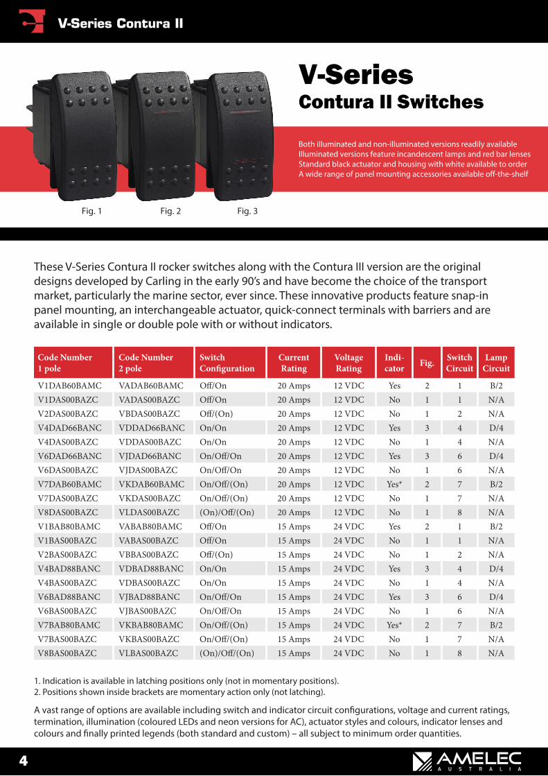
V1DAB60BAMC VADAB60BAMC 20 Amps 12 VDC Yes 2 1 B/2V1DAS00BAZC VADAS00BAZC 20 Amps 12 VDC No 1 1 N/AV2DAS00BAZC VBDAS00BAZC 20 Amps 12 VDC No 1 2 N/AV4DAD66BANC VDDAD66BANC On/On 20 Amps 12 VDC Yes 3 4 D/4V4DAS00BAZC VDDAS00BAZC On/On 20 Amps 12 VDC No 1 4 N/AV6DAD66BANC VJDAD66BANC 20 Amps 12 VDC Yes 3 6 D/4V6DAS00BAZC VJDAS00BAZC 20 Amps 12 VDC No 1 6 N/AV7DAB60BAMC VKDAB60BAMC 20 Amps 12 VDC Yes* 2 7 B/2V7DAS00BAZC VKDAS00BAZC 20 Amps 12 VDC No 1 7 N/AV8DAS00BAZC VLDAS00BAZC 20 Amps 12 VDC No 1 8 N/AV1BAB80BAMC VABAB80BAMC 15 Amps 24 VDC Yes 2 1 B/2V1BAS00BAZC VABAS00BAZC 15 Amps 24 VDC No 1 1 N/AV2BAS00BAZC VBBAS00BAZC 15 Amps 24 VDC No 1 2 N/AV4BAD88BANC VDBAD88BANC On/On 15 Amps 24 VDC Yes 3 4 D/4V4BAS00BAZC VDBAS00BAZC On/On 15 Amps 24 VDC No 1 4 N/AV6BAD88BANC VJBAD88BANC 15 Amps 24 VDC Yes 3 6 D/4V6BAS00BAZC VJBAS00BAZC 15 Amps 24 VDC No 1 6 N/AV7BAB80BAMC VKBAB80BAMC 15 Amps 24 VDC Yes* 2 7 B/2V7BAS00BAZC VKBAS00BAZC 15 Amps 24 VDC No 1 7 N/AV8BAS00BAZC VLBAS00BAZC 15 Amps 24 VDC No 1 8 N/A
These V-Series Contura II rocker switches along with the Contura III version are the original designs developed by Carling in the early 90’s and have become the choice of the transport market, particularly the marine sector, ever since. These innovative products feature snap-in panel mounting, an interchangeable actuator, quick-connect terminals with barriers and are available in single or double pole with or without indicators.
Both illuminated and non-illuminated versions readily availableIlluminated versions feature incandescent lamps and red bar lensesStandard black actuator and housing with white available to orderA wide range of panel mounting accessories available o�-the-shelf
V-SeriesContura II Switches
Fig. 1 Fig. 2 Fig. 3
4
V-Series Contura II
1. Indication is available in latching positions only (not in momentary positions).2. Positions shown inside brackets are momentary action only (not latching).
A vast range of options are available including switch and indicator circuit con�gurations, voltage and current ratings, termination, illumination (coloured LEDs and neon versions for AC), actuator styles and colours, indicator lenses and colours and �nally printed legends (both standard and custom) – all subject to minimum order quantities.
Code Number 1 pole
Code Number 2 pole
Switch CurrentRating
VoltageRating
Indi-cator Fig. Switch
CircuitLamp
Circuit
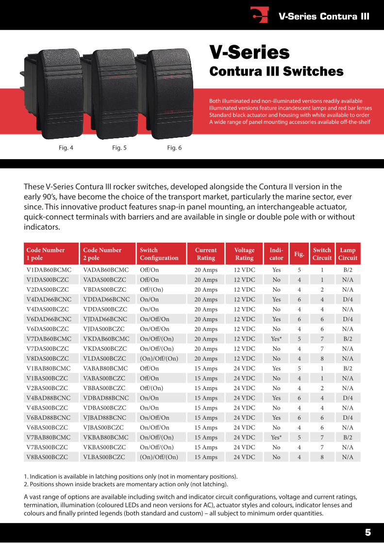
V1DAB60BCMC VADAB60BCMC 20 Amps 12 VDC Yes 5 1 B/2V1DAS00BCZC VADAS00BCZC 20 Amps 12 VDC No 4 1 N/AV2DAS00BCZC VBDAS00BCZC 20 Amps 12 VDC No 4 2 N/AV4DAD66BCNC VDDAD66BCNC On/On 20 Amps 12 VDC Yes 6 4 D/4V4DAS00BCZC VDDAS00BCZC On/On 20 Amps 12 VDC No 4 4 N/AV6DAD66BCNC VJDAD66BCNC 20 Amps 12 VDC Yes 6 6 D/4V6DAS00BCZC VJDAS00BCZC 20 Amps 12 VDC No 4 6 N/AV7DAB60BCMC VKDAB60BCMC 20 Amps 12 VDC Yes* 5 7 B/2V7DAS00BCZC VKDAS00BCZC 20 Amps 12 VDC No 4 7 N/AV8DAS00BCZC VLDAS00BCZC 20 Amps 12 VDC No 4 8 N/AV1BAB80BCMC VABAB80BCMC 15 Amps 24 VDC Yes 5 1 B/2V1BAS00BCZC VABAS00BCZC 15 Amps 24 VDC No 4 1 N/AV2BAS00BCZC VBBAS00BCZC 15 Amps 24 VDC No 4 2 N/AV4BAD88BCNC VDBAD88BCNC On/On 15 Amps 24 VDC Yes 6 4 D/4V4BAS00BCZC VDBAS00BCZC On/On 15 Amps 24 VDC No 4 4 N/AV6BAD88BCNC VJBAD88BCNC 15 Amps 24 VDC Yes 6 6 D/4V6BAS00BCZC VJBAS00BCZC 15 Amps 24 VDC No 4 6 N/AV7BAB80BCMC VKBAB80BCMC 15 Amps 24 VDC Yes* 5 7 B/2V7BAS00BCZC VKBAS00BCZC 15 Amps 24 VDC No 4 7 N/AV8BAS00BCZC VLBAS00BCZC 15 Amps 24 VDC No 4 8 N/A
These V-Series Contura III rocker switches, developed alongside the Contura II version in the early 90’s, have become the choice of the transport market, particularly the marine sector, ever since. This innovative product features snap-in panel mounting, an interchangeable actuator, quick-connect terminals with barriers and are available in single or double pole with or without indicators.
Both illuminated and non-illuminated versions readily availableIlluminated versions feature incandescent lamps and red bar lensesStandard black actuator and housing with white available to orderA wide range of panel mounting accessories available o�-the-shelf
V-SeriesContura III Switches
Fig. 4 Fig. 5 Fig. 6
V-Series Contura III
5

1. Indication is available in latching positions only (not in momentary positions).2. Positions shown inside brackets are momentary action only (not latching).
A vast range of options are available including switch and indicator circuit con�gurations, voltage and current ratings, termination, illumination (coloured LEDs and neon versions for AC), actuator styles and colours, indicator lenses and colours and �nally printed legends (both standard and custom) – all subject to minimum order quantities.
Code Number 1 pole
Code Number 2 pole
Switch CurrentRating
VoltageRating
Indi-cator Fig. Switch
CircuitLamp
Circuit
V1DAB60BGMC VADAB60BGMC 20 Amps 12 VDC Yes 8 1 B/2V1DAS00BGZC VADAS00BGZC 20 Amps 12 VDC No 7 1 N/AV2DAS00BGZC VBDAS00BGZC 20 Amps 12 VDC No 7 2 N/AV4DAD66BGNC VDDAD66BGNC On/On 20 Amps 12 VDC Yes 9 4 D/4V4DAS00BGZC VDDAS00BGZC On/On 20 Amps 12 VDC No 7 4 N/AV6DAD66BGNC VJDAD66BGNC 20 Amps 12 VDC Yes 9 6 D/4V6DAS00BGZC VJDAS00BGZC 20 Amps 12 VDC No 7 6 N/AV7DAB60BGMC VKDAB60BGMC 20 Amps 12 VDC Yes* 8 7 B/2V7DAS00BGZC VKDAS00BGZC 20 Amps 12 VDC No 7 7 N/AV8DAS00BGZC VLDAS00BGZC 20 Amps 12 VDC No 7 8 N/AV1BAB80BGMC VABAB80BGMC 15 Amps 24 VDC Yes 8 1 B/2V1BAS00BGZC VABAS00BGZC 15 Amps 24 VDC No 7 1 N/AV2BAS00BGZC VBBAS00BGZC 15 Amps 24 VDC No 7 2 N/AV4BAD88BGNC VDBAD88BGNC On/On 15 Amps 24 VDC Yes 9 4 D/4V4BAS00BGZC VDBAS00BGZC On/On 15 Amps 24 VDC No 7 4 N/AV6BAD88BGNC VJBAD88BGNC 15 Amps 24 VDC Yes 9 6 D/4V6BAS00BGZC VJBAS00BGZC 15 Amps 24 VDC No 7 6 N/AV7BAB80BGMC VKBAB80BGMC 15 Amps 24 VDC Yes* 8 7 B/2V7BAS00BGZC VKBAS00BGZC 15 Amps 24 VDC No 7 7 N/AV8BAS00BGZC VLBAS00BGZC 15 Amps 24 VDC No 7 8 N/A
Following the success of the original Contura II and III series, the Contura V (�ve) version was released in 2004. Featuring a symmetrically sculptured design and a combination of �ne and polished surfaces the Contura V has become a popular choice for both vessel and vehicle applications. Like the originals, the Contura V features the same mounting, terminals, illumination and switching con�gurations.
Both illuminated and non-illuminated versions readily availableIlluminated versions feature incandescent lamps and red bar lensesStandard black actuator and housing with white available to orderA wide range of panel mounting accessories available o�-the-shelf
V-SeriesContura V Switches
Fig. 7 Fig. 8 Fig. 9
6
V-Series Contura V
1. Indication is available in latching positions only (not in momentary positions).2. Positions shown inside brackets are momentary action only (not latching).
A vast range of options are available including switch and indicator circuit con�gurations, voltage and current ratings, termination, illumination (coloured LEDs and neon versions for AC), actuator styles and colours, indicator lenses and colours and �nally printed legends (both standard and custom) – all subject to minimum order quantities.
Code Number 1 pole
Code Number 2 pole
Switch CurrentRating
VoltageRating
Indi-cator Fig. Switch
CircuitLamp
Circuit
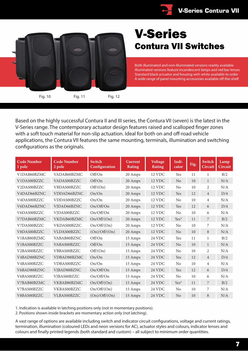
V1DAB60BZMC VADAB60BZMC 20 Amps 12 VDC Yes 11 1 B/2V1DAS00BZZC VADAS00BZZC 20 Amps 12 VDC No 10 1 N/AV2DAS00BZZC VBDAS00BZZC 20 Amps 12 VDC No 10 2 N/AV4DAD66BZNC VDDAD66BZNC On/On 20 Amps 12 VDC Yes 12 4 D/4V4DAS00BZZC VDDAS00BZZC On/On 20 Amps 12 VDC No 10 4 N/AV6DAD66BZNC VJDAD66BZNC 20 Amps 12 VDC Yes 12 6 D/4V6DAS00BZZC VJDAS00BZZC 20 Amps 12 VDC No 10 6 N/AV7DAB60BZMC VKDAB60BZMC 20 Amps 12 VDC Yes* 11 7 B/2V7DAS00BZZC VKDAS00BZZC 20 Amps 12 VDC No 10 7 N/AV8DAS00BZZC VLDAS00BZZC 20 Amps 12 VDC No 10 8 N/AV1BAB80BZMC VABAB80BZNC 15 Amps 24 VDC Yes 11 1 B/2V1BAS00BZZC VABAS00BZZC 15 Amps 24 VDC No 10 1 N/AV2BAS00BZZC VBBAS00BZZC 15 Amps 24 VDC No 10 2 N/AV4BAD88BZNC VDBAD88BZMC On/On 15 Amps 24 VDC Yes 12 4 D/4V4BAS00BZZC VDBAS00BZZC On/On 15 Amps 24 VDC No 10 4 N/AV6BAD88BZNC VJBAD88BZNC 15 Amps 24 VDC Yes 12 6 D/4V6BAS00BZZC VJBAS00BZZC 15 Amps 24 VDC No 10 6 N/AV7BAB80BZMC VKBAB80BZMC 15 Amps 24 VDC Yes* 11 7 B/2V7BAS00BZZC VKBAS00BZZC 15 Amps 24 VDC No 10 7 N/AV8BAS00BZZC VLBAS00BZZC 15 Amps 24 VDC No 10 8 N/A
Based on the highly successful Contura II and III series, the Contura VII (seven) is the latest in the V-Series range. The contemporary actuator design features raised and scalloped �nger zones with a soft touch material for non-slip actuation. Ideal for both on and o�-road vehicle applications, the Contura VII features the same mounting, terminals, illumination and switching con�gurations as the originals.
Both illuminated and non-illuminated versions readily availableIlluminated versions feature incandescent lamps and red bar lensesStandard black actuator and housing with white available to orderA wide range of panel mounting accessories available o�-the-shelf
V-SeriesContura VII Switches
Fig. 10 Fig. 11 Fig. 12
7
V-Series Contura VII
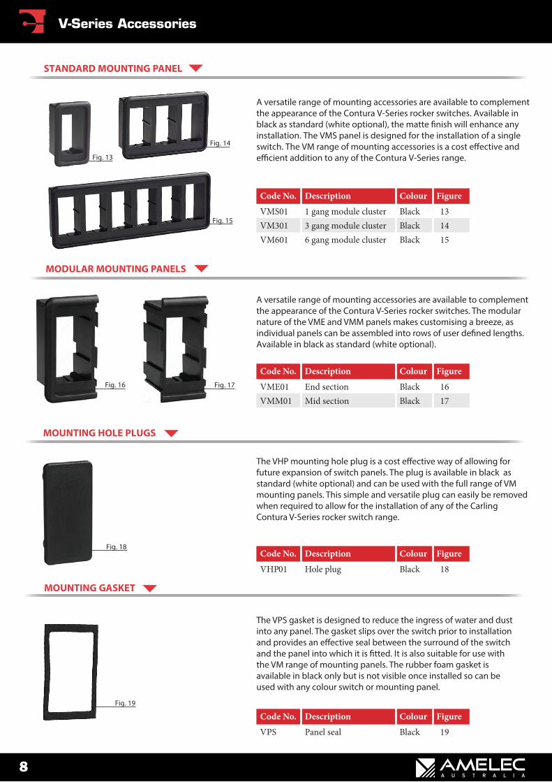
Fig. 13
Fig. 14
Fig. 15
The VHP mounting hole plug is a cost e�ective way of allowing for future expansion of switch panels. The plug is available in black as standard (white optional) and can be used with the full range of VM mounting panels. This simple and versatile plug can easily be removed when required to allow for the installation of any of the Carling Contura V-Series rocker switch range.
Fig. 18
MOUNTING HOLE PLUGS
Code No. Description Colour Figure
VHP01 Hole plug Black 18
A versatile range of mounting accessories are available to complement the appearance of the Contura V-Series rocker switches. The modular nature of the VME and VMM panels makes customising a breeze, as individual panels can be assembled into rows of user de�ned lengths. Available in black as standard (white optional).
MODULAR MOUNTING PANELS
Fig. 16 Fig. 17
Code No. Description Colour Figure
VME01 End section Black 16VMM01 Mid section Black 17
Code No. Description Colour Figure
VMS01 1 gang module cluster Black 13VM301 3 gang module cluster Black 14VM601 6 gang module cluster Black 15
A versatile range of mounting accessories are available to complementthe appearance of the Contura V-Series rocker switches. Available inblack as standard (white optional), the matte �nish will enhance anyinstallation. The VMS panel is designed for the installation of a singleswitch. The VM range of mounting accessories is a cost e�ective and e�cient addition to any of the Contura V-Series range.
STANDARD MOUNTING PANEL
The VPS gasket is designed to reduce the ingress of water and dustinto any panel. The gasket slips over the switch prior to installation and provides an e�ective seal between the surround of the switchand the panel into which it is �tted. It is also suitable for use with the VM range of mounting panels. The rubber foam gasket is available in black only but is not visible once installed so can be used with any colour switch or mounting panel.
Fig. 19
MOUNTING GASKET
Code No. Description Colour Figure
VPS Panel seal Black 19
8
V-Series Accessories
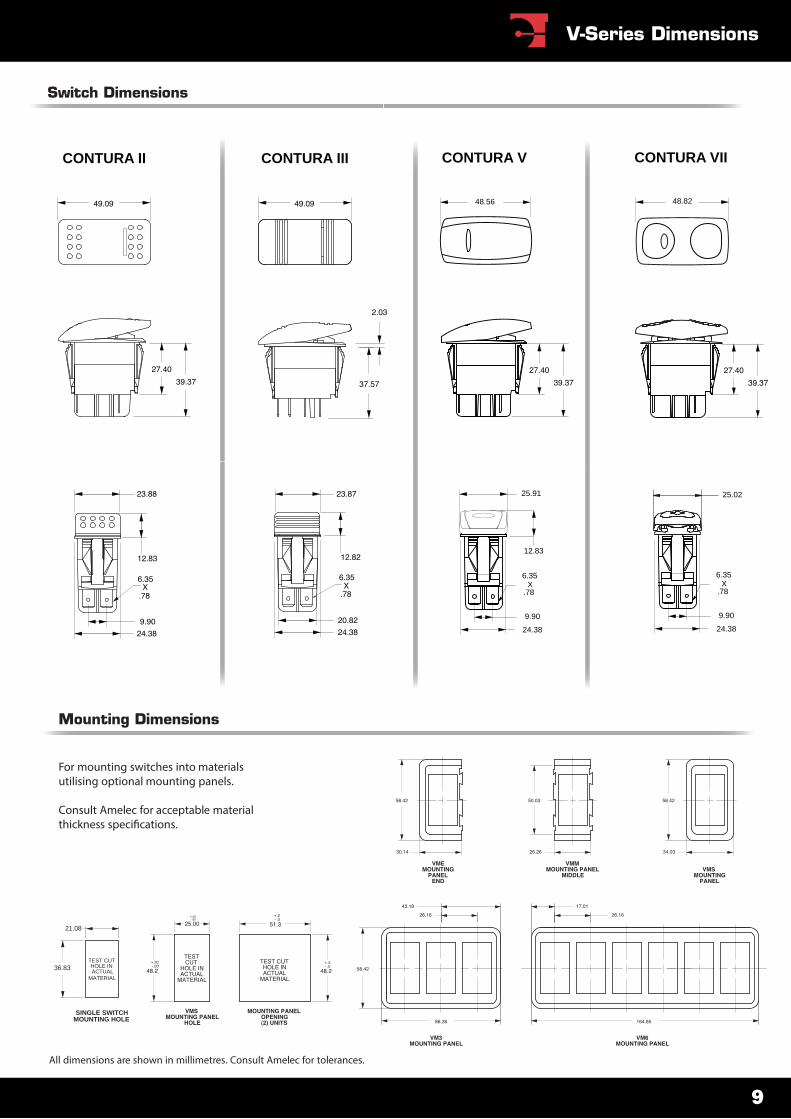
Switch Dimensions
CONTURA II CONTURA III CONTURA V
12.83
6.35 X
.78
25.91
9.90
24.38
48.56
6.35 X
.78
9.90
24.38
25.02
48.82
CONTURA VII
36.83
21.08
SINGLE SWITCHMOUNTING HOLE
TEST CUTHOLE INACTUAL
MATERIAL
All dimensions are shown in millimetres. Consult Amelec for tolerances.
For mounting switches into materials utilising optional mounting panels.
Consult Amelec for acceptable material thickness speci�cations.
Mounting Dimensions
9
V-Series Dimensions
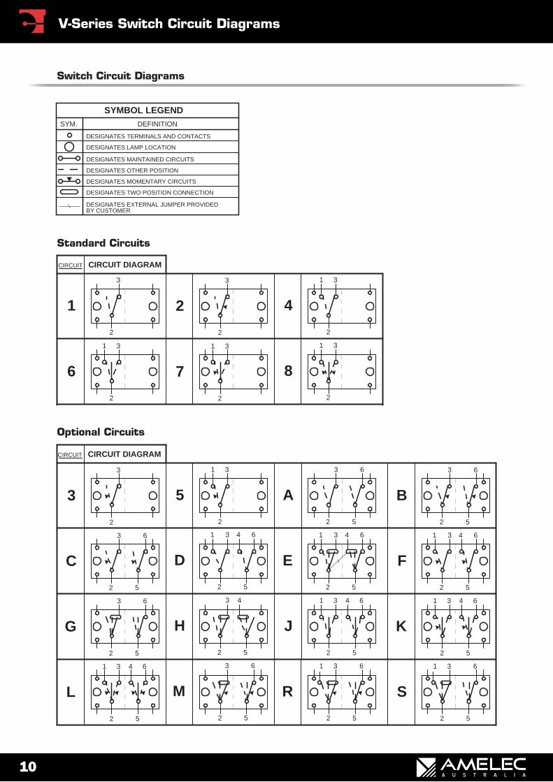
Switch Circuit Diagrams
DEFINITIONSYM.
SYMBOL LEGEND
DESIGNATES TERMINALS AND CONTACTS
DESIGNATES LAMP LOCATION
DESIGNATES MAINTAINED CIRCUITS
DESIGNATES OTHER POSITION
DESIGNATES MOMENTARY CIRCUITS
DESIGNATES TWO POSITION CONNECTION
DESIGNATES EXTERNAL JUMPER PROVIDED BY CUSTOMER
3
2
2 4
1 3
1 3
6
1 3
2
8
2
31
2
7
22
CIRCUIT
1
3
CIRCUIT DIAGRAM
2 5
1 3 4 6 6431
CIRCUIT
A
J
3
2 5
3
63
2
3 4 6
L M
5
52
K
1
52
D
431
C
3
2
B
5
31
R
2 552
1 3 6
S
6
F
1 3
E
522 5
3
434 1
43
2 5
H
2 5
6
CIRCUIT DIAGRAM
66
6
66
6
G
52
52
3 5
3
2
31
2
Standard Circuits
Optional Circuits
10
V-Series Switch Circuit Diagrams
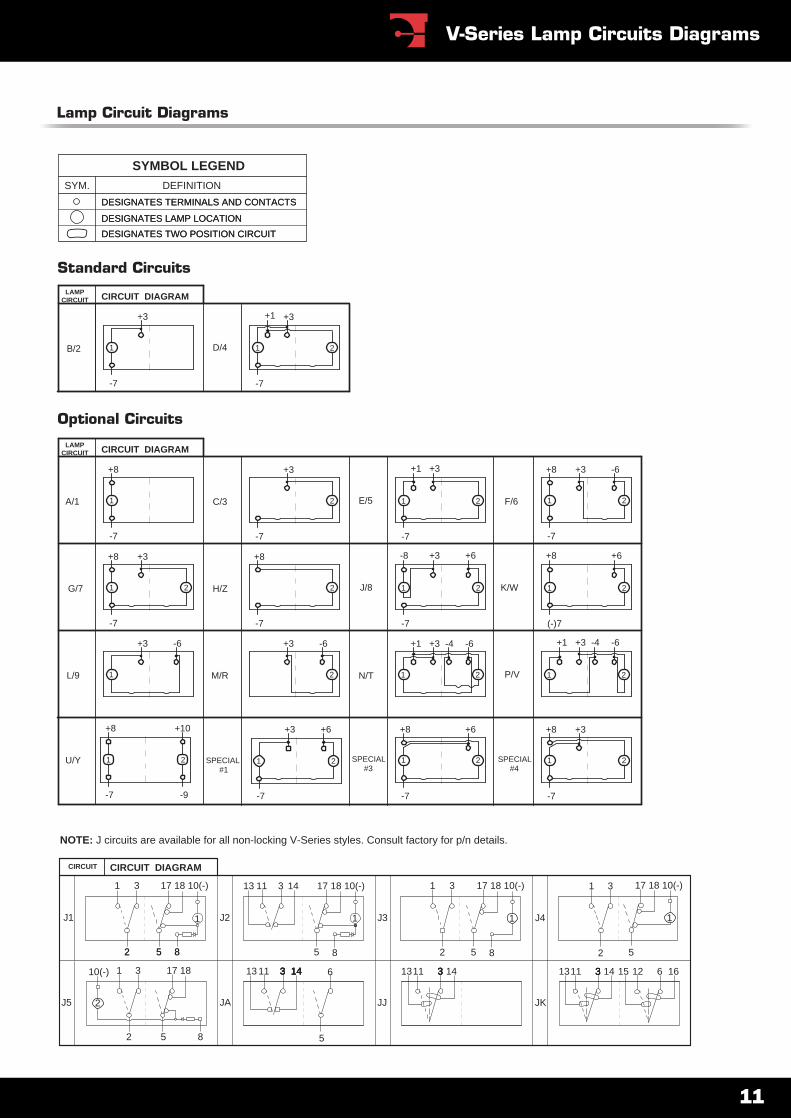
Lamp Circuit Diagrams
22 8855
3
85
3
1
17 18 10(-) 17 18 10(-)
CIRCUIT DIAGRAM
1431
1 1
17 18 10(-) 17 18 10(-)
1
1
2 5 8 2
31
5
J3 J4J2
CIRCUIT
J1
1113
16314143
5
14 633 143 14 333
JA
612153333 14
JKJJ
131113 11 111317 18
5 8
2
2
10(-) 1 3
J5
NOTE: J circuits are available for all non-locking V-Series styles. Consult factory for p/n details.
1
+8 +3
-7
SPECIAL#4
21SPECIAL#1
2
-7
+6+3
1
+6+8
2SPECIAL#3
-7
LAMPCIRCUIT
C/3
+1 +3
A/1 1
-7
E/5 2
CIRCUIT DIAGRAM
G/7
F/6
+3
1 2
+8
J/8H/Z
+8 +6
-7
1 2
-8 +6
2
-7
+3 +8
1 2K/W
(-)7-7
L/9
+10
212
-4 -6+3+1
1
+8
M/R P/VN/T
+1 -6+3 -4
-7 -9
1 2U/Y
+3
2
-6+3 -6
1
1
-7
+8 -6+3
2
-7
+3
2
+8
1
-7
Optional Circuits
LAMPCIRCUIT
1
+3
D/4
-7
+3
1
+1
B/2
CIRCUIT DIAGRAM
2
-7
Standard Circuits
SYMBOL LEGENDDEFINITIONSYM.
DESIGNATES TERMINALS AND CONTACTS
DESIGNATES LAMP LOCATION
DESIGNATES TWO POSITION CIRCUIT
DESIGNATES TERMINALS AND CONTACTS
DESIGNATES LAMP LOCATION
DESIGNATES TWO POSITION CIRCUIT
11
V-Series Lamp Circuits Diagrams
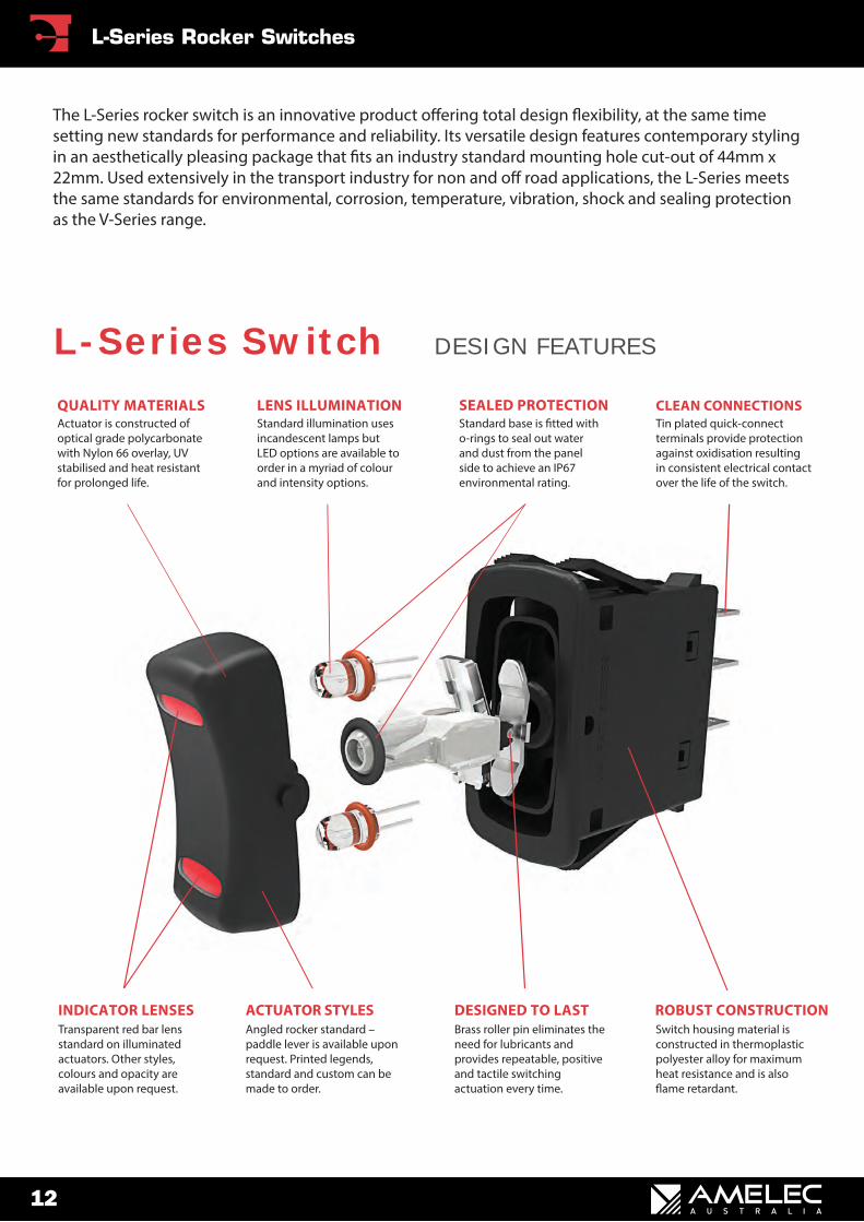
Switch housing material is constructed in thermoplastic polyester alloy for maximum heat resistance and is also �ame retardant.
ROBUST CONSTRUCTIONBrass roller pin eliminates the need for lubricants and provides repeatable, positive and tactile switching actuation every time.
DESIGNED TO LASTAngled rocker standard – paddle lever is available upon request. Printed legends, standard and custom can be made to order.
ACTUATOR STYLESTransparent red bar lens standard on illuminated actuators. Other styles, colours and opacity are available upon request.
INDICATOR LENSES
Tin plated quick-connect terminals provide protection against oxidisation resulting in consistent electrical contact over the life of the switch.
CLEAN CONNECTIONSStandard base is �tted with o-rings to seal out water and dust from the panel side to achieve an IP67 environmental rating.
SEALED PROTECTIONStandard illumination uses incandescent lamps but LED options are available to order in a myriad of colour and intensity options.
LENS ILLUMINATIONActuator is constructed of optical grade polycarbonate with Nylon 66 overlay, UV stabilised and heat resistant for prolonged life.
QUALITY MATERIALS
L-Series Switch DESIGN FEATURES
The L-Series rocker switch is an innovative product o�ering total design �exibility, at the same time setting new standards for performance and reliability. Its versatile design features contemporary styling in an aesthetically pleasing package that �ts an industry standard mounting hole cut-out of 44mm x 22mm. Used extensively in the transport industry for non and o� road applications, the L-Series meets the same standards for environmental, corrosion, temperature, vibration, shock and sealing protection as the V-Series range.
12
L-Series Rocker Switches
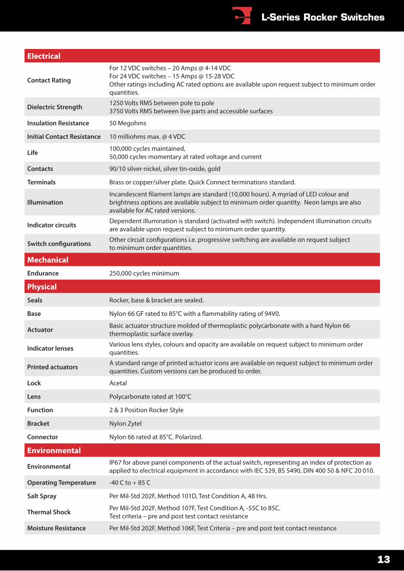
Electrical
Contact Rating
For 12 VDC switches – 20 Amps @ 4-14 VDC For 24 VDC switches – 15 Amps @ 15-28 VDCOther ratings including AC rated options are available upon request subject to minimum order quantities.
Dielectric Strength 1250 Volts RMS between pole to pole3750 Volts RMS between live parts and accessible surfaces
Insulation Resistance 50 Megohms
Initial Contact Resistance 10 milliohms max. @ 4 VDC
Life 100,000 cycles maintained,50,000 cycles momentary at rated voltage and current
Contacts 90/10 silver-nickel, silver tin-oxide, gold
Terminals Brass or copper/silver plate. Quick Connect terminations standard.
Illumination brightness options are available subject to minimum order quantity. Neon lamps are also available for AC rated versions.
Indicator circuits Dependent illumination is standard (activated with switch). Independent illumination circuits are available upon request subject to minimum order quantity.
to minimum order quantities.
Mechanical
Endurance 250,000 cycles minimum
Physical
Seals Rocker, base & bracket are sealed.
Base
Actuator Basic actuator structure molded of thermoplastic polycarbonate with a hard Nylon 66thermoplastic surface overlay.
Indicator lenses Various lens styles, colours and opacity are available on request subject to minimum order quantities.
Printed actuators A standard range of printed actuator icons are available on request subject to minimum order quantities. Custom versions can be produced to order.
Lock Acetal
Lens Polycarbonate rated at 100°C
Function 2 & 3 Position Rocker Style
Bracket Nylon Zytel
Connector Nylon 66 rated at 85°C. Polarized.
Environmental
Environmental IP67 for above panel components of the actual switch, representing an index of protection as applied to electrical equipment in accordance with IEC 529, BS 5490, DIN 400 50 & NFC 20 010.
Operating Temperature -40 C to + 85 C
Salt Spray Per Mil-Std 202F, Method 101D, Test Condition A, 48 Hrs.
Thermal Shock Per Mil-Std 202F, Method 107F, Test Condition A, -55C to 85C.Test criteria – pre and post test contact resistance
Moisture Resistance Per Mil-Std 202F, Method 106F, Test Criteria – pre and post test contact resistance
13
L-Series Rocker Switches
1. Indication is available in latching positions only (not in momentary positions).2. Positions shown inside brackets are momentary action only (not latching).
A vast range of options are available including switch and indicator circuit con�gurations, voltage and current ratings, termination, illumination (coloured LEDs and neon versions for AC), actuator styles and colours, indicator lenses and colours and �nally printed legends (both standard and custom) – all subject to minimum order quantities.
Code Number 1 pole
Code Number 2 pole
Switch CurrentRating
VoltageRating
Indi-cator Fig. Switch
CircuitLamp
Circuit
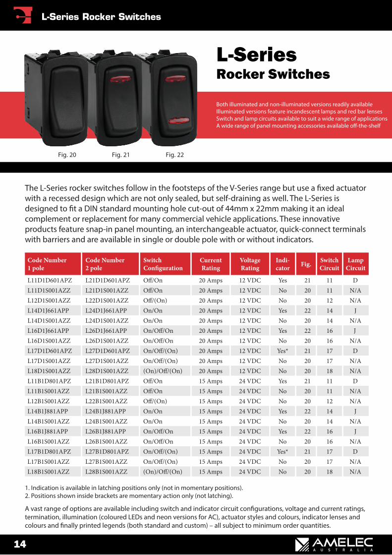
L11D1D601APZ L21D1D601APZ 20 Amps 12 VDC Yes 21 11 DL11D1S001AZZ L21D1S001AZZ 20 Amps 12 VDC No 20 11 N/AL12D1S001AZZ L22D1S001AZZ 20 Amps 12 VDC No 20 12 N/AL14D1J661APP L24D1J661APP On/On 20 Amps 12 VDC Yes 22 14 JL14D1S001AZZ L24D1S001AZZ On/On 20 Amps 12 VDC No 20 14 N/AL16D1J661APP L26D1J661APP 20 Amps 12 VDC Yes 22 16 JL16D1S001AZZ L26D1S001AZZ 20 Amps 12 VDC No 20 16 N/AL17D1D601APZ L27D1D601APZ 20 Amps 12 VDC Yes* 21 17 DL17D1S001AZZ L27D1S001AZZ 20 Amps 12 VDC No 20 17 N/AL18D1S001AZZ L28D1S001AZZ 20 Amps 12 VDC No 20 18 N/AL11B1D801APZ L21B1D801APZ 15 Amps 24 VDC Yes 21 11 DL11B1S001AZZ L21B1S001AZZ 15 Amps 24 VDC No 20 11 N/AL12B1S001AZZ L22B1S001AZZ 15 Amps 24 VDC No 20 12 N/AL14B1J881APP L24B1J881APP On/On 15 Amps 24 VDC Yes 22 14 JL14B1S001AZZ L24B1S001AZZ On/On 15 Amps 24 VDC No 20 14 N/AL16B1J881APP L26B1J881APP 15 Amps 24 VDC Yes 22 16 JL16B1S001AZZ L26B1S001AZZ 15 Amps 24 VDC No 20 16 N/AL17B1D801APZ L27B1D801APZ 15 Amps 24 VDC Yes* 21 17 DL17B1S001AZZ L27B1S001AZZ 15 Amps 24 VDC No 20 17 N/AL18B1S001AZZ L28B1S001AZZ 15 Amps 24 VDC No 20 18 N/A
The L-Series rocker switches follow in the footsteps of the V-Series range but use a �xed actuator with a recessed design which are not only sealed, but self-draining as well. The L-Series is designed to �t a DIN standard mounting hole cut-out of 44mm x 22mm making it an ideal complement or replacement for many commercial vehicle applications. These innovative products feature snap-in panel mounting, an interchangeable actuator, quick-connect terminals with barriers and are available in single or double pole with or without indicators.
Both illuminated and non-illuminated versions readily availableIlluminated versions feature incandescent lamps and red bar lensesSwitch and lamp circuits available to suit a wide range of applicationsA wide range of panel mounting accessories available o�-the-shelf
L-SeriesRocker Switches
Fig. 22Fig. 21Fig. 20
14
L-Series Rocker Switches
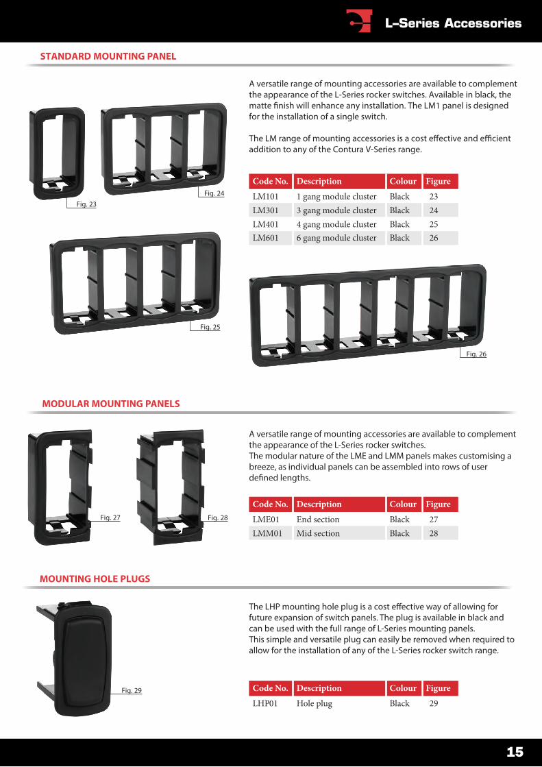
The LHP mounting hole plug is a cost e�ective way of allowing for future expansion of switch panels. The plug is available in black and can be used with the full range of L-Series mounting panels.This simple and versatile plug can easily be removed when required to allow for the installation of any of the L-Series rocker switch range.
Fig. 29
MOUNTING HOLE PLUGS
Code No. Description Colour Figure
LHP01 Hole plug Black 29
A versatile range of mounting accessories are available to complement the appearance of the L-Series rocker switches.The modular nature of the LME and LMM panels makes customising a breeze, as individual panels can be assembled into rows of user de�ned lengths.
MODULAR MOUNTING PANELS
Fig. 27 Fig. 28
Code No. Description Colour Figure
LME01 End section Black 27LMM01 Mid section Black 28
Code No. Description Colour Figure
LM101 1 gang module cluster Black 23LM301 3 gang module cluster Black 24LM401 4 gang module cluster Black 25LM601 6 gang module cluster Black 26
A versatile range of mounting accessories are available to complement the appearance of the L-Series rocker switches. Available in black, the matte �nish will enhance any installation. The LM1 panel is designed for the installation of a single switch.
The LM range of mounting accessories is a cost e�ective and e�cient addition to any of the Contura V-Series range.
STANDARD MOUNTING PANEL
Fig. 26
Fig. 25
Fig. 24Fig. 23
15
L–Series Accessories
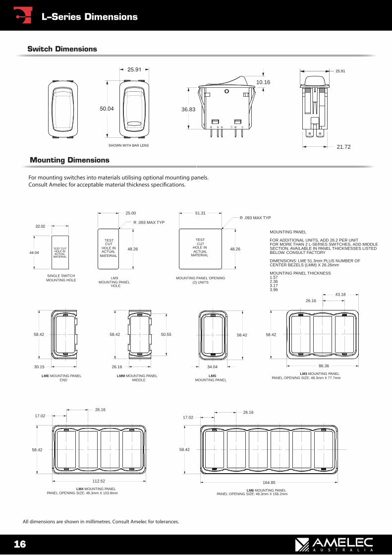
21.72
25.91
36.83
10.16
Switch Dimensions
TESTCUT
HOLE INACTUAL
MATERIAL
51.31
TESTCUT
HOLE INACTUAL
MATERIAL
25.00
48.26
R .093 MAX TYP
48.26
R .093 MAX TYP
LMSMOUNTING PANEL
HOLE
MOUNTING PANEL OPENING(2) UNITS
MOUNTING PANEL
FOR ADDITIONAL UNITS, ADD 26.2 PER UNITFOR MORE THAN 2 L-SERIES SWITCHES, ADD MIDDLESECTION. AVAILABLE IN PANEL THICKNESSES LISTEDBELOW. CONSULT FACTORY
DIMENSIONS: LME 51.3mm PLUS NUMBER OFCENTER BEZELS (LMM) X 26.26mm
MOUNTING PANEL THICKNESS1.572.363.173.96
30.15
LMM MOUNTING PANELMIDDLE
26.16
LMSMOUNTING PANEL
34.04
58.42 58.42 50.55
LME MOUNTING PANELEND
58.42
17.02
58.42
LM4 MOUNTING PANELPANEL OPENING SIZE: 48.3mm X 103.9mm
26.16
112.52
43.18
58.42
26.16
86.36
LM3 MOUNTING PANELPANEL OPENING SIZE: 48.3mm X 77.7mm
164.85
58.42
26.16
LM6 MOUNTING PANELPANEL OPENING SIZE: 48.3mm X 156.2mm
17.02
Mounting Dimensions
For mounting switches into materials utilising optional mounting panels. Consult Amelec for acceptable material thickness speci�cations.
All dimensions are shown in millimetres. Consult Amelec for tolerances.
MOUNTING HOLESINGLE SWITCH
16
L–Series Dimensions
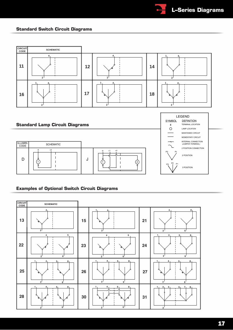
Examples of Optional Switch Circuit Diagrams
Standard Lamp Circuit Diagrams
CIRCUITCODE
SCHEMATIC
2
4
2
4
2
41
2
41
2
41
2
41
11 12 14
16 17 18
Standard Switch Circuit Diagrams
17
L–Series Diagrams
1. Positions shown inside brackets are momentary action only (not latching).2. Code numbers above are also rated for AC use – details available upon request.3. Push on termination is 6.25mm blade. Screw tab is 6-32 UNC with wire clamp.4. Standard hardware supplied is one piece each of knurled face nut and hex back-up nut.
A vast range of options are available including switch and indicator circuit con�gurations, voltage and current ratings, termination, illumination (coloured LEDs and neon versions for AC), actuator styles and colours, indicator lenses and colours and �nally printed legends (both standard and custom) – all subject to minimum order quantities.
Code No. Termination 12 VDC Rating 24 VDC Rating
2FA5378 Push On 21 Amps 9 Amps6FA5378 Push On 21 Amps 9 Amps2FB5378 On/On Push On 21 Amps 9 Amps2FC5378 Push On 21 Amps 9 Amps6FC5778 Push On 21 Amps 9 Amps6FC5378 Push On 21 Amps 9 Amps2FA5478 Screw Clamp 21 Amps 9 Amps6FA5878 Screw Clamp 21 Amps 9 Amps2FB5478 On/On Screw Clamp 21 Amps 9 Amps2FC5478 Screw Clamp 21 Amps 9 Amps6FC5878 Screw Clamp 21 Amps 9 Amps6FC5478 Screw Clamp 21 Amps 9 Amps
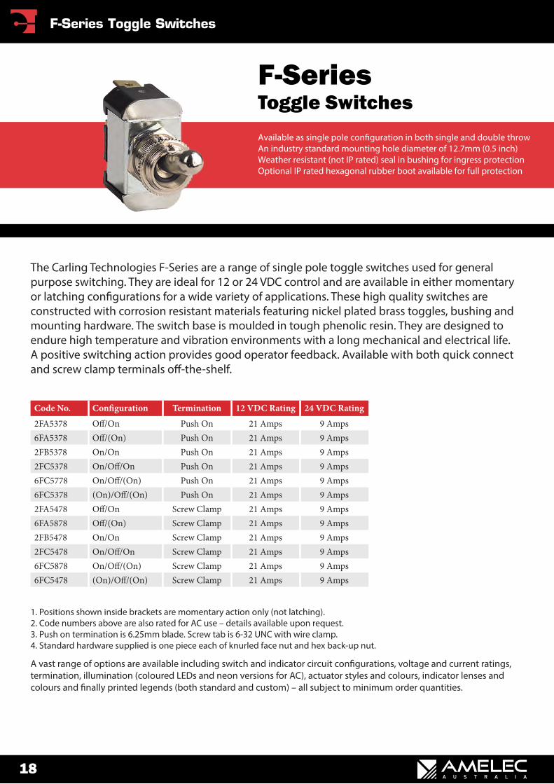
The Carling Technologies F-Series are a range of single pole toggle switches used for general purpose switching. They are ideal for 12 or 24 VDC control and are available in either momentary or latching con�gurations for a wide variety of applications. These high quality switches are constructed with corrosion resistant materials featuring nickel plated brass toggles, bushing and mounting hardware. The switch base is moulded in tough phenolic resin. They are designed to endure high temperature and vibration environments with a long mechanical and electrical life. A positive switching action provides good operator feedback. Available with both quick connect and screw clamp terminals o�-the-shelf.
Available as single pole con�guration in both single and double throwAn industry standard mounting hole diameter of 12.7mm (0.5 inch)Weather resistant (not IP rated) seal in bushing for ingress protectionOptional IP rated hexagonal rubber boot available for full protection
F-SeriesToggle Switches
18
F-Series Toggle Switches
1. Positions shown inside brackets are momentary action only (not latching).2. Code numbers above are also rated for AC use – details available upon request.3. Push on termination is 6.25mm blade. Screw tab is 6-32 UNC with wire clamp.4. Standard hardware supplied is one piece each of knurled face nut and hex back-up nut.
A vast range of options are available including switch and indicator circuit con�gurations, voltage and current ratings, termination, illumination (coloured LEDs and neon versions for AC), actuator styles and colours, indicator lenses and colours and �nally printed legends (both standard and custom) – all subject to minimum order quantities.
Code No. Termination 12 VDC Rating 24 VDC Rating
2GK5178 Push On 21 Amps 9 Amps6GK5B78 Push On 21 Amps 9 Amps2GL5178 On/On Push On 21 Amps 9 Amps2GM5178 Push On 21 Amps 9 Amps6GM5B78 Push On 21 Amps 9 Amps6GM5M78 Push On 21 Amps 9 Amps2GK5478 Screw Clamp 21 Amps 9 Amps6GK5E78 Screw Clamp 21 Amps 9 Amps2GL5478 On/On Screw Clamp 21 Amps 9 Amps2GM5478 Screw Clamp 21 Amps 9 Amps6GM5E78 Screw Clamp 21 Amps 9 Amps6GM5S78 Screw Clamp 21 Amps 9 Amps
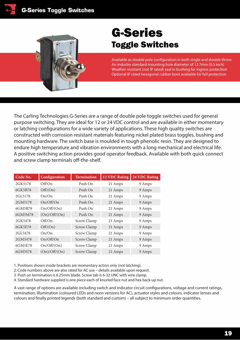
The Carling Technologies G-Series are a range of double pole toggle switches used for general purpose switching. They are ideal for 12 or 24 VDC control and are available in either momentary or latching con�gurations for a wide variety of applications. These high quality switches are constructed with corrosion resistant materials featuring nickel plated brass toggles, bushing and mounting hardware. The switch base is moulded in tough phenolic resin. They are designed to endure high temperature and vibration environments with a long mechanical and electrical life. A positive switching action provides good operator feedback. Available with both quick connect and screw clamp terminals o�-the-shelf.
G-SeriesToggle SwitchesAvailable as double pole con�guration in both single and double throwAn industry standard mounting hole diameter of 12.7mm (0.5 inch)Weather resistant (not IP rated) seal in bushing for ingress protectionOptional IP rated hexagonal rubber boot available for full protection
19
G-Series Toggle Switches
19.0533.22
19.76
THREAD
17.44
10.72
11.81
/ KEYWAY1.82
X.965 DP
9.65
1.57
MOUNTING HOLE WITH KEYWAY
9.55
WITH LOCKING RING
DIA DIA
DIADIA
KEYWAY1.82
X.965 DP
THREAD
11.81
8.84
17.02
28.80 16.10
17.44
/
MOUNTING HOLE WITH KEYWAY WITH LOCKING RING
12.70 DIA1.57
12.70 DIA9.55
12.70 DIA
3.17 DIA9.65
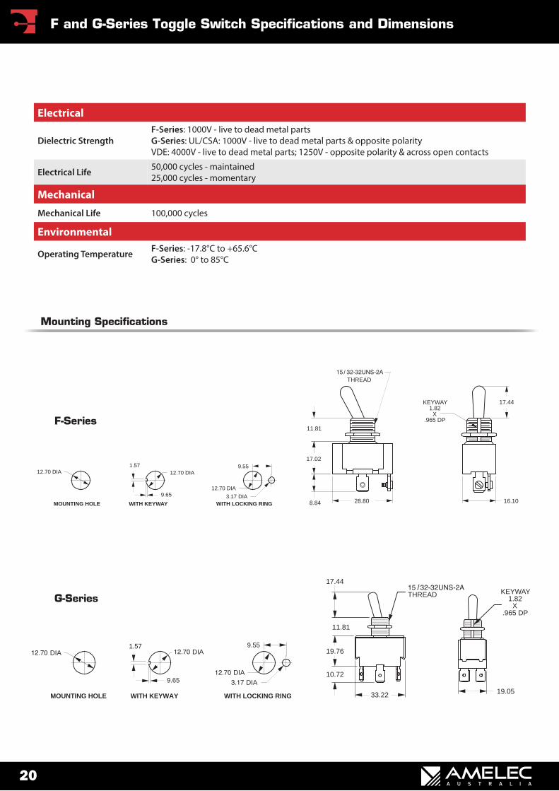
Mounting Specifications
G-Series
F-Series
Electrical
Dielectric StrengthF-Series: 1000V - live to dead metal partsG-Series: UL/CSA: 1000V - live to dead metal parts & opposite polarity VDE: 4000V - live to dead metal parts; 1250V - opposite polarity & across open contacts
Electrical Life 50,000 cycles - maintained 25,000 cycles - momentary
Mechanical
Mechanical Life 100,000 cycles
Environmental
Operating Temperature F-Series: -17.8°C to +65.6°CG-Series: 0° to 85°C
20
F and G-Series Toggle Switch Specifications and Dimensions
21
Warranty
©2016 - Amelec Australia Pty Ltd. ABN 38 009 386 216.
All rights reserved. �is catalogue may not be reproduced in full or part, by any means, without the express written permission of the copyright owners.
Disclaimer: E & O.E. - the information and speci�cations detailed in this catalogue were deemed to be accurate at the time of printing. Amelec Australia Pty Ltd reserves the right, subject to Australian law, at its discretion and without notice, to change the information and speci�cations contained within.
Amelec Australia Pty Ltd warrants all Carling products against defects in factory workmanship and materials for a period of 12 months from �nal point of sale providing the item in question does not exceed the manufacture date by more than 2 (two) years. Speci�c exclusions of this warranty apply where the item in question has been misapplied or used for a purpose for which it is not designed or intended; or altered in any way that would be detrimental to the performance or life of the product; or opened or tampered with by an unauthorised party; or contaminated by oil, water, grease or other substances; or subjected to misuse, negligence, excessive vibration or mechanical abuse; or damaged as a result of incorrect connection or voltage. On any part or product found to be defective after examination by Amelec Australia Pty Ltd or their authorised agent, Amelec Australia will only repair or replace the merchandise through the original selling dealer. Amelec Australia assumes no responsibility for diagnosis, removal and/or installation labour, loss of equipment use, loss of time, inconvenience or any other subsequent expenses including freight costs. Save and except for the express warranty set out above and to the maximum extent permitted by law, all conditions and warranties which may at any time be implied by the common law, Trade Practices Act, Fair Trading Act or any other State or Federal Act are excluded. To the extent that these cannot be excluded and where the law permits, Amelec Australia liability in respect of any such condition or warranty shall be limited at the option of Amelec Australia to the repair or the replacement of the goods or the supply of equivalent goods or refunding the cost of the goods. Amelec Australia Pty Ltd A.B.N. 38 009 386 216

16 Parkinson Lane, O’ConnorWA 6163 AustraliaPhone +61 8 9331 3100Fax +61 8 9331 5150Email [email protected] www.amelec.com.au