cap 8300 foi pbn operational approval handbook …dgca.nic.in/manuals/cap8300_foipbn.pdf · foi pbn...
TRANSCRIPT

CA FOHa Appr Seco Dire
AP 83
OI PBandbo
roved b
ond Edi
ectorate
300
BN Opook
by the D
ition – 2
e Gener
perat
Director
2014
ral of C
tiona
Genera
Civil Avi
al Ap
al of Civ
iation
pprov
il Aviati
val
on

FOI PBN Operational Approval Handbook
CAP 8300
Chapter 0
Revision 0 October 2014
2
Foreword
The purpose of this Handbook is to provide guidance to personnel responsible for the assessment of applications for operational approval to conduct Performance Based Navigation Operations. Over the years, a number of regions have established local RNAV and RNP standards which led to complexity in international operations and operational approvals. ICAO has developed the concept of Performance Based Navigation and harmonized the concepts and requirements which are now contained in the ICAO Doc 9613 Performance Based Navigation (PBN) Manual. The Handbook supplements the information contained in the PBN Manual related to operational approval of PBN. DGCA staff will adhere to the policy and procedures contained in this Handbook when authorizing PBN operations. Because of the wide scope of operations involved and the many variables that can be encountered in aircraft equipment, it is impossible to anticipate all situations, therefore DGCA personnel must exercise common sense and good judgement in the application of these policies and procedures.
Dr Prabhat Kumar
Director General Civil Aviation
DGCA
October 2014 File No AV 22024/36/2014-FSD
INTRODUCTION
The Handbook is divided into two parts.
Part 1 PBN Technology provides a summary of the enabling area navigation technology in order to provide operational approval inspectors with the technical background necessary for an informed and consistent management of PBN operational approvals. Additional study may be required depending upon the complexity of the operation and other factors, and reference is made in Part 3 to suitable sources of information.
Typically the operational approval process for established navigation technologies is well known and understood by inspectors and there is general consistency amongst regulators world wide in the issue of operational approvals. As Performance Based Navigation is a relatively recent development, regulatory authorities, inspectors and applicants require some time and experience to develop a thorough understanding of PBN operations, the associated technology and the approval process. In addition, some work remains to be done in the development of regulatory and guidance material and it is necessary that inspectors have a good knowledge of PBN principles, the associated technology and operating practices in order to accommodate any perceived limitations in the available documentation.
Part 2 PBN Operations discusses the approval of operations for each of the Navigation Specifications included in the PBN Manual. Where appropriate additional guidance material is provided to explain the context or intent of the navigation specification.
It is intended that this Handbook is supplemented by a formal course of training for inspectors.
FOI PBN Operational Approval Handbook
CAP 8300
Chapter 0
Revision 0 October 2014
4
CONTENTS
INTRODUCTION 3 DEFINITIONS 9 ACRONYMS 11 Chapter 1 OVERVIEW 15 1.1 Introduction. 15 1.2 Transition from Conventional Navigation to PBN 15 1.3 Performance Based Navigation 16 1.4 RNAV vs. RNP 16 Chapter 2 AREA NAVIGATION 18 2.1 Area Navigation Principles 18 2.2 Geodetic Reference 18 2.3 Path Terminators 18 2.4 Radius to Fix segments 21 2.5 Area Navigation Systems 23 2.6 Data Management 24 Chapter 3 NAVIGATION PERFORMANCE 26 3.1 General 26 3.2 Performance Evaluation 26 3.3 Performance Components 28 3.4 Required Navigation Performance 31 3.5 Performance Limitations 32 3.6 Flight Technical Error Management 33 3.7 Lateral Deviation Monitoring 35 3.8 Vertical Deviation Monitoring 36 3.9 Evaluation of Deviation Displays 37 Chapter 4 GNSS 38 4.1 General 38 4.2 Monitoring and alerting 40 4.3 GNSS Accuracy 40 4.4 Integrity Monitoring 40 4.5 Fault Detection 41
FOI PBN Operational Approval Handbook
CAP 8300
Chapter 0
Revision 0 October 2014
5
4.6 Horizontal Protection Level 41 4.7 Integrity Alerting 43 4.8 Loss of Integrity Monitoring Function 44 4.9 Availability Prediction 44 4.10 Augmentation systems 45 Chapter 5 ROUTE DESIGN 47 5.1 Protected Area 47 5.2 RNP AR APCH 47 5.3 RNP APCH 48 5.4 En-route and Terminal 48 Chapter 6 BAROMETRIC VERTICAL NAVIGATION 50 6.1 General 50 6.2 Baro-VNAV Principles 50 6.3 Limitations of the Baro VNAV System 52 6.4 Aircraft Capability 54 6.5 Flight Procedure Design 55 6.6 Baro VNAV Operations 57 Chapter 7 AIRCRAFT QUALIFICATION 59 7.1 Eligibility 59 7.2 Aircraft Evaluation 59 7.3 Functionality 60 Chapter 8 FLIGHT CREW TRAINING 62 8.1 General 62 8.2 Knowledge requirements 62 8.3 Flight Training requirements 63 PART 2 PBN OPERATIONAL APPROVALS 65 Chapter 1 Overview 65 1.1 General 65 1.2 Responsibility for Operational Approval Evaluation 65 1.3 Issue of Approval 65 1.4 Job Aids 66 Chapter 2 RNAV 10 67
FOI PBN Operational Approval Handbook
CAP 8300
Chapter 0
Revision 0 October 2014
6
2.1 General 67 2.2 ATS communications and surveillance 67 2.3 Summary 67 2.4 Operating Procedures 68 2.5 Pilot Knowledge and Training 69 Chapter 3 RNAV 5 70 3.1 General 70 3.2 Summary 70 3.3 INS or IRS 70 3.4 GNSS 70 3.5 Operating procedures 71 3.6 Pilot Knowledge and Training 71 3.7 Operational Approval 71 Chapter 4 RNAV 1 and 2 72 4.1 General 72 4.2 Operational Approval 72 4.3 Summary 72 4.4 GNSS 73 4.5 Functionality 73 4.6 Operating procedures 74 4.7 Pilot Knowledge and Training 74 Chapter 5 RNP 4 76 5.1 General 76 5.2 Operational Approval 76 5.3 ATS communications and surveillance 76 5.4 Summary 76 5.5 GNSS 76 5.6 Functionality 77 5.7 Operating Procedures 77 5.8 Pilot Knowledge and Training 78 Chapter 6 RNP 2 Reserved 79 Chapter 7 Basic RNP 1 80
FOI PBN Operational Approval Handbook
CAP 8300
Chapter 0
Revision 0 October 2014
7
7.1 General 80 7.2 Operational Approval 80 7.3 Summary 80 7.4 Stand-alone GNSS systems 80 7.5 RNP Systems 81 7.6 Integrity availability 81 7.7 Deselection of radio updating 82 7.8 Functionality 82 7.9 Operating procedures 82 7.10 Pilot Knowledge and Training 83 Chapter 8 Advanced RNP Reserved 84 Chapter 9 RNP APCH 85 9.1 General 85 9.2 Characteristics 85 9.3 Flight procedure design 85 9.4 Operational approval 88 9.5 Navigation systems 88 9.6 Stand-alone systems 89 9.7 Flight Management Systems 91 9.8 Using VNAV advisory information 93 9.9 VNAV approach guidance 94 9.10 Altimeter setting procedures 95 9.11 Vertical Navigation Systems 95 9.12 GNSS Availability Prediction. 96 9.13 Radio updating. 97 9.14 Operating Procedures 98 9.15 Procedure selection and review 98 9.16 Use of autopilot and flight director 98 9.17 GNSS updating 98 9.18 Flight crew knowledge and training 99 9.19 Navigation Database 99 Chapter 10 RNP AR APCH 101
FOI PBN Operational Approval Handbook
CAP 8300
Chapter 0
Revision 0 October 2014
8
10.1 General 101 10.2 Authorisation Required 101 10.3 Characteristics 102 10.4 Procedure Design 102 10.5 Operational Approval 103 10.6 Evaluation Team 104 10.7 Operator’s Application 104 10.8 Aircraft Eligibility 104 10.9 Flight Technical Error 105 10.10 Demonstration of Path Steering Performance 107 10.11 Navigation System Monitoring and Alerting 108 10.12 GNSS latent failure protection 108 10.13 Operating Procedures 109 10.14 RNP Availability Prediction. 109 10.15 Radio updating. 110 10.16 Procedure selection and review 111 10.17 Required list of equipment. 111 10.18 Use of autopilot and flight director 112 10.19 RNP selection. 112 10.20 GNSS updating 112 10.21 Track deviation monitoring. 112 10.22 Vertical Navigation 114 10.23 Vertical deviation monitoring. 116 10.24 Maximum airspeeds 116 10.25 Limiting temperature 117 10.26 Altimeter setting procedures 117 10.27 TOGA Navigation Functionality 117 10.28 Navigation Database 117 10.29 Flight crew training 118 10.30 Flight Operational Safety Assessment (FOSA) 119
FOI PBN Operational Approval Handbook
CAP 8300
Chapter 0
Revision 0 October 2014
9
DEFINITIONS
Aircraft-based augmentation system (ABAS) - A system which augments and/or integrates the information obtained from the other GNSS elements with information available on board the aircraft. The most common form of ABAS is the receiver autonomous integrity monitoring (RAIM).
Area navigation (RNAV) - A navigation method that allows aircraft to operate on any desired flight path within the coverage of ground- or space-based navigation aids, or within the limits of the capability of self-contained aids, or a combination of both methods.
Flight technical error (FTE) - The FTE is the accuracy with which an aircraft is controlled as measured by the indicated aircraft position with respect to the indicated command or desired position. It does not include blunder errors.
Global navigation satellite system (GNSS) - A generic term used by the International Civil Aviation Organization (ICAO) to define any global position, speed, and time determination system that includes one or more main satellite constellations, such as GPS and the global navigation satellite system (GLONASS), aircraft receivers and several integrity monitoring systems, including aircraft-based augmentation systems (ABAS), satellite-based augmentation systems (SBAS), such as the wide area augmentation systems (WAAS), and ground-based augmentation systems (GBAS), such as the local area augmentation system (LAAS).
Global positioning system (GPS) - The global positioning system (GPS) of the United States is a satellite-based radio navigation system that uses precise distance measurements to determine the position, speed, and time in any part of the world. The GPS is made up by three elements: the spatial, the control, and the user elements. The GPS spatial segment nominally consists of, at least, 24 satellites in 6 orbital planes. The control element consists of 5 monitoring stations, 3 ground antennas, and one main control station. The user element consists of antennas and receivers that provide the user with position, speed, and precise time.
Navigation specifications - Set of aircraft and flight crew requirements needed to support performance-based navigation operations in a defined airspace. There are two kinds of navigation specifications:
Required Navigation Performance (RNP) Specification - Area navigation specification that includes the performance control and alerting requirement, designated by the prefix RNP; e.g., RNP 4, RNP APCH, RNP AR APCH.
Area Navigation (RNAV) Specification - Area navigation specification that does not include the performance control and alerting requirement, designated by the prefix RNAV; e.g., RNAV 5, RNAV 2, RNAV 1.
Navigation system error (NSE) - The difference between the true position and the estimated position.
Path definition error (PDE) - The difference between the defined path and the desired path at a given place and time.
FOI PBN Operational Approval Handbook
CAP 8300
Chapter 0
Revision 0 October 2014
10
Performance-based navigation (PBN) - Performance-based area navigation requirements applicable to aircraft conducting operations on an ATS route, on an instrument approach procedure, or in a designated airspace.
Receiver autonomous integrity monitoring (RAIM) - A technique used in a GPS receiver/processor to determine the integrity of its navigation signals, using only GPS signals or GPS signals enhanced with barometric altitude data. This determination is achieved by a consistency check between redundant pseudo-range measurements. At least one additional available satellite is required with respect to the number of satellites that are needed for the navigation solution.
RNP operations - Aircraft operations that use an RNP system for RNP applications.
RNP system - An area navigation system that supports on-board performance control and alerting.
Standard instrument arrival (STAR) - A designated instrument flight rules (IFR) arrival route linking a significant point, normally on an air traffic service (ATS) route, with a point from which a published instrument approach procedure can be commenced.
Standard instrument departure (SID) - A designated instrument flight rule (IFR) departure route linking the aerodrome or a specified runway of the aerodrome with a specified significant point, normally on a designated ATS route, at which the en-route phase of a flight commences.
Total system error (TSE) - The difference between the true position and the desired position. This error is equal to the sum of the vectors of the path definition error (PDE), the flight technical error (FTE), and the navigation system error (NSE). Note. - FTE is also known as path steering error (PSE), and the NSE as position estimation error (PEE).
Way-point (WPT) - A specified geographical location used to define an area navigation route or the flight path of an aircraft employing area navigation. Way-points area identified as either:
Fly-by way-point - A way-point which requires turn anticipation to allow tangential interception of the next segment of a route or procedure.
Fly over way-point - A way-point at which a turn is initiated in order to join the next segment of a route or procedure.
FOI PBN Operational Approval Handbook
CAP 8300
Chapter 0
Revision 0 October 2014
11
ACRONYMS
ABAS Aircraft-based augmentation system
AC Advisory circular (FAA)
AFM Aircraft flight manual
AIP Aeronautical information publication
AIRAC Aeronautical information regulation and control
ANSP Air navigation service provider
AP Automatic pilot
APV Approach procedure with vertical guidance
ARP Aerodrome reference point
ATC Air traffic control
ATM Air traffic management
ATS Air traffic service
Baro-VNAV Barometric vertical navigation
CA Course to an altitude
CDI Course deviation indicator
CDU Control and display unit
CF Course to a fix
Doc Document
DF Direct to a fix
DME Distance-measuring equipment
EASA European Air Safety Agency
EGPWS Enhanced ground proximity warning system
EHSI Electronic horizontal situation indicator
FAA Federal Aviation Administration (United States)
FAF Final approach fix
FAP Final approach point
FD Flight director
FD Fault detection
FDE Fault detection and exclusion
FM Course from a fix to a manual termination
FOI PBN Operational Approval Handbook
CAP 8300
Chapter 0
Revision 0 October 2014
12
FMS Flight management system
FOI Flight Operations Inspector
FOSA Flight Operational Safety Assessment
FTE Flight technical error
GBAS Ground-based augmentation system
GNSS Global navigation satellite system (ICAO)
GLONASS Global navigation satellite system (Russia)
GPS Global positioning system (US)
GS Ground speed
HAL Horizontal alert limit
HIL Horizontal integrity limit
HPL Horizontal Protection Level
HSI Vertical status indicator
HUGS Head up guidance system
ICAO International Civil Aviation Organization
IF Initial fix
IFR Instrument flight rules
IMC Instrument meteorological conditions
LAAS Local area augmentation system
LNAV Lateral navigation
LOA Letter of authorisation/letter of acceptance
LPV Localizer Performance with Vertical Guidance
MCDU Multi-function control and display
MEL Minimum equipment list
MOC Minimum Obstacle Clearance
NM Nautical miles
NAVAIDS Navigation aids
NOTAM Notice to airmen
NPA Non-precision approach
NSE Navigation system error
OM Operations manual
OEM Original equipment manufacturer
FOI PBN Operational Approval Handbook
CAP 8300
Chapter 0
Revision 0 October 2014
13
OPSPEC Operations specification
PA Precision approach
PANS-ATM Procedures for Air Navigation Services - Air Traffic Management
PANS-OPS Procedures for Air Navigation Services - Aircraft Operations
PBN Performance-based navigation
PDE Path definition error
PEE Position estimation error
PF Pilot flying
PNF Pilot not flying
PM Pilot monitoring
POH Pilot operating handbook
P-RNAV Precision area navigation
PSE Path steering error
QAR Quick access recorder
RAIM Receiver autonomous integrity monitoring
RNAV Area navigation
RNP Required navigation performance
RNP APCH Required navigation performance approach
RNP AR APCH Required navigation performance authorisation required approach
RTCA Radio Technical Commission for Aviation
SBAS Satellite-based augmentation system
SID Standard instrument departure
SRVSOP Regional Safety Oversight Cooperation System
STAR Standard instrument arrival
STC Supplemental type certificate
TAWS Terrain awareness system
TF Track to fix
TSE Total system error
TSO Technical standard order
VA Heading to an altitude
VI Heading to an intercept
FOI PBN Operational Approval Handbook
CAP 8300
Chapter 0
Revision 0 October 2014
14
VM Heading to a manual termination
VMC Visual meteorological conditions
WAAS Wide area augmentation system
WGS World geodetic system
WPR Waypoint Precision Error
WPT Waypoint
FOI PBN Operational Approval Handbook
CAP 8300
Chapter 0
Revision 0 October 2014
15
PART 1 PBN TECHNOLOGY Chapter 1 OVERVIEW 1.1 Introduction. The information in this Part is intended to provide inspectors with the necessary technical knowledge necessary to manage an application for operational approval in accordance with a navigation specification contained in the PBN Manual. This Part contains information relative to the full complement of PBN Manual navigation specifications and in general individual PBN operations are not discussed in detail.
1.2 Transition from Conventional Navigation to PBN Conventional navigation, that is navigation dependent upon ground-based radio navigation aids, has long been the mainstay of aviation. Pilots, operators, manufacturers and ANSPs are all familiar with the technology, and the avionics, instrumentation, operations, training and performance are very much standard throughout the world. Consequently, apart from some more demanding operations such as Cat II/III ILS, specific operational approval is not necessary.
Performance Based Navigation is dependent on area navigation, and while various methods of RNAV have been in existence for many years, the use of RNAV has not yet reached the same level of common use as conventional navigation. The Performance Based Navigation concept is intended to better define the use of RNAV systems and provide a means to eventually reach a similar level of common use. However, until there is general
FOI PBN Operational Approval Handbook
CAP 8300
Chapter 0
Revision 0 October 2014
16
standardisation in aircraft, operating procedures, training and ATS application, there is a need for an operational approval process.
While there is a need for an approval process, the fundamentals of PBN operations are relatively straightforward, and operational approval need not be a complicated process for either applicant or regulator. Even the highest performing type of operation (RNP AR APCH), once implemented, due the capability of modern avionics and auto-flight systems, is a simple and safe operation when conducted in an appropriately equipped aircraft operated by a properly trained crew.
However the transition to new technology, new navigation and operational concepts and the dependence on data driven operations requires careful management. It is the purpose of the operational approval process to ensure that for all PBN operations the appropriate level of oversight is provided to ensure that in the current environment where there are many variables in terms of equipment and experience that the benefits of PBN can be achieved consistently and safely.
The key to successful PBN implementation is knowledge and experience. For many States, both operators and regulators lack both, and this handbook is intended to assist in improving that level of knowledge. Experience can only be gained by doing, and an operational approval will commonly be required before relevant experience is gained. In this handbook guidance is also provided on strategies for implementation which allow experience to be gained (by all parties) in a controlled environment, allowing progression to full capability in stages as experience is gained.
1.3 Performance Based Navigation Performance Based Navigation encompasses a range of operations which are all based upon Area Navigation. Area navigation, commonly abbreviated as RNAV, has been available for around 30 years using a variety of technologies, however some difficulties arise in the dual application of the term RNAV as a fundamental method of navigation (area navigation) and also as a particular type of operation (e.g. RNAV 5). Further complications arise with the implementation of Required Navigation Performance (RNP) operations which by definition are also area navigation operations.
There has been some difficulty in identifying the differences between RNAV operations and RNP operations, and some lack of definition in the requirements for both RNAV and RNP operations. A number of regions established local RNAV and RNP standards which led to complexity in international operations and operational approvals.
ICAO established the Required Navigation and Special Operational Requirements Study Group (RNPSORSG) to resolve these issues. The RNPSORSG (now called the PBN Study Group) developed the concept of Performance Based Navigation to encompass both RNAV and RNP operations.
1.4 RNAV vs. RNP One of the issues that the RNPSORSG had to deal with was to differentiate between area navigation operations which are described as either RNAV or RNP. It was recognised that while both RNAV and RNP operations could be described in terms of navigation performance (e.g. accuracy), RNP operations can be identified by the capability of the on-board navigation system to monitor in real time the achieved navigation performance and to alert the operating
FOI PBN Operational Approval Handbook
CAP 8300
Chapter 0
Revision 0 October 2014
17
crew when the specified minimum performance appropriate to a particular operation could not be met. This additional functionality provided by RNP allows the flight crew to intervene and to take appropriate mitigating action (e.g. a go-round), thereby allowing RNP operations to provide an additional level of safety and capability over RNAV operations.
As GNSS systems incorporate performance monitoring and alerting, the distinction between RNAV and RNP operations in practice is the requirement for GNSS. While there are exceptions to this rule, in simple terms RNP operations are GNSS based, and for RNAV operations are based on older technology.
RNAV navigation specifications have been developed to support existing capability in aircraft equipped with systems which in the general case were not designed to provide on-board performance monitoring and alerting.
RNP navigation specifications have been developed from a need to support operations that depend upon GNSS to provide the required performance.
FOI PBN Operational Approval Handbook
CAP 8300
Chapter 0
Revision 0 October 2014
18
Chapter 2 AREA NAVIGATION 2.1 Area Navigation Principles Area navigation (RNAV) is a term applied to navigation between any two selected points on the earth’s surface. RNAV has been around since the 1960s and the earliest avionics used triangulation measurements from ground-based navigation aids to compute an RNAV flight path between waypoints.
A number of self-contained navigation systems which are independent of any ground based navigation systems have also been developed, including OMEGA (now obsolete) LORAN C, GPS, Glonass, Inertial Navigation Systems (INS) and Inertial Reference Systems (IRS).
Perhaps the most common type of RNAV system in use in commercial aviation today involves the use of IRS positioning updated by reference to ground-based radio navigation aids (DME and VOR) or GPS. Updating by reference to ground-based aids is limited by the availability of sufficient navigation aids, and in many parts of the world, including oceanic and remote areas, position updating is unavailable.
Commonly referred to by the generic term GNSS (Global Navigation Satellite System) satellite navigation has revolutionised area navigation and provides highly accurate and reliable positioning. For modern air transport operations area navigation is managed using a Flight Management System, using IRS position updated by GNSS.
However, as there are many and varied area navigation systems in use throughout the world, the PBN Manual provides a number of navigation specifications to accommodate a range of RNAV and RNP performance levels. One of the tasks of the operations approval inspector is to ensure that the equipment available meets the requirements of the relevant PBN operation.
2.2 Geodetic Reference An area navigation system computed position must be translated to provide position relative to the real position on the earth’s surface. Horizontal datums are used for describing a point on the earth's surface, in latitude and longitude or another coordinate system.
A specific point on the earth can have substantially different coordinates, depending on the datum used to make the measurement. There are hundreds of locally-developed horizontal datums around the world, usually referenced to some convenient local reference point. The WGS 84 datum is the common standard datum now used in aviation.
2.3 Path Terminators In its simplest form area navigation system computes a track between two selected waypoints. However the demands on aircraft navigation require the definition of complex flight paths, both lateral and vertical. The international standard for definition of path and terminator is ARINC 424. A flight path is described in coded ARINC 424 language which is interpreted by the RNAV system to provide the desired navigation function and inputs to flight guidance systems.
The path between any two waypoints can be specified, depending upon the coding. Each segment is also defined by a terminator or end statement, which provides information to the navigation system on the intended method of connection of one segment (path) with the next.
For ex(TF) odefineIn gesometand th
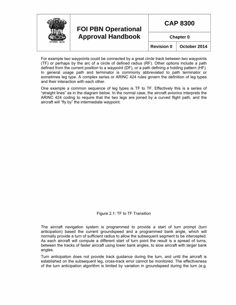
One e“straigARINCaircraf
The aanticipnormaAs eabetweangles
Turn aestablof the
xample two wor perhaps bed from the cneral usagetimes leg typheir interactio
example a cght lines” as C 424 codinft will “fly by”
aircraft navipation) baseally provide aach aircraft wen the tracks.
anticipation ished on theturn anticip
FOI PAppr
waypoints coby the arc ocurrent posite path andpe. A complon with each
common seqin the diagra
ng to require” the interme
gation systeed the currea turn of suffwill computeks of faster a
does not pe subsequenpation algorit
PBN Oproval Ha
ould be connof a circle ofion to a way terminatorex series or
h other.
quence of leam below. Ine that the twediate waypo
Figure 2.1
em is progent groundsficient radiuse a differentaircraft using
rovide tracknt leg, crossthm is limite
perationandboo
nected by a f defined ra
ypoint (DF), r is commor ARINC 424
eg types is n the normawo legs are oint.
1: TF to TF T
grammed tospeed and s to allow thet start of turg lower bank
k guidance ds-track error ed by variati
nal ok
Re
great circle adius (RF). Oor a path de
only abbrevi4 rules gove
TF to TF. El case, the ajoined by a
Transition
o provide a a programme subsequenrn point thek angles, to
during the tcannot be m
ion in groun
CAP
Cha
evision 0
track betweeOther optionefining a holdiated to paern the defin
Effectively thaircraft aviona curved flig
start of tumed bank ant segment t
e result is a slow aircraft
turn, and unmonitored. T
ndspeed dur
P 8300
apter 0
October
en two waypns include ading pattern ath terminatnition of leg
his is a serinics interpretght path, an
urn prompt angle, whichto be intercespread of t
t with larger
ntil the aircrThe effectivering the turn
2014
points a path
(HF). or or types
ies of ts the d the
(turn h will epted. turns, bank
raft is eness (e.g.
FOI PBN Operational Approval Handbook
CAP 8300
Chapter 0
Revision 0 October 2014
20
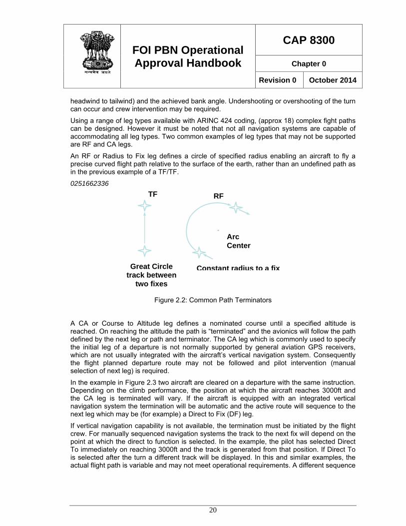
TF
Great Circle track between
two fixes
RF
Arc Center
Constant radius to a fix
headwind to tailwind) and the achieved bank angle. Undershooting or overshooting of the turn can occur and crew intervention may be required.
Using a range of leg types available with ARINC 424 coding, (approx 18) complex fight paths can be designed. However it must be noted that not all navigation systems are capable of accommodating all leg types. Two common examples of leg types that may not be supported are RF and CA legs.
An RF or Radius to Fix leg defines a circle of specified radius enabling an aircraft to fly a precise curved flight path relative to the surface of the earth, rather than an undefined path as in the previous example of a TF/TF.
0251662336
Figure 2.2: Common Path Terminators
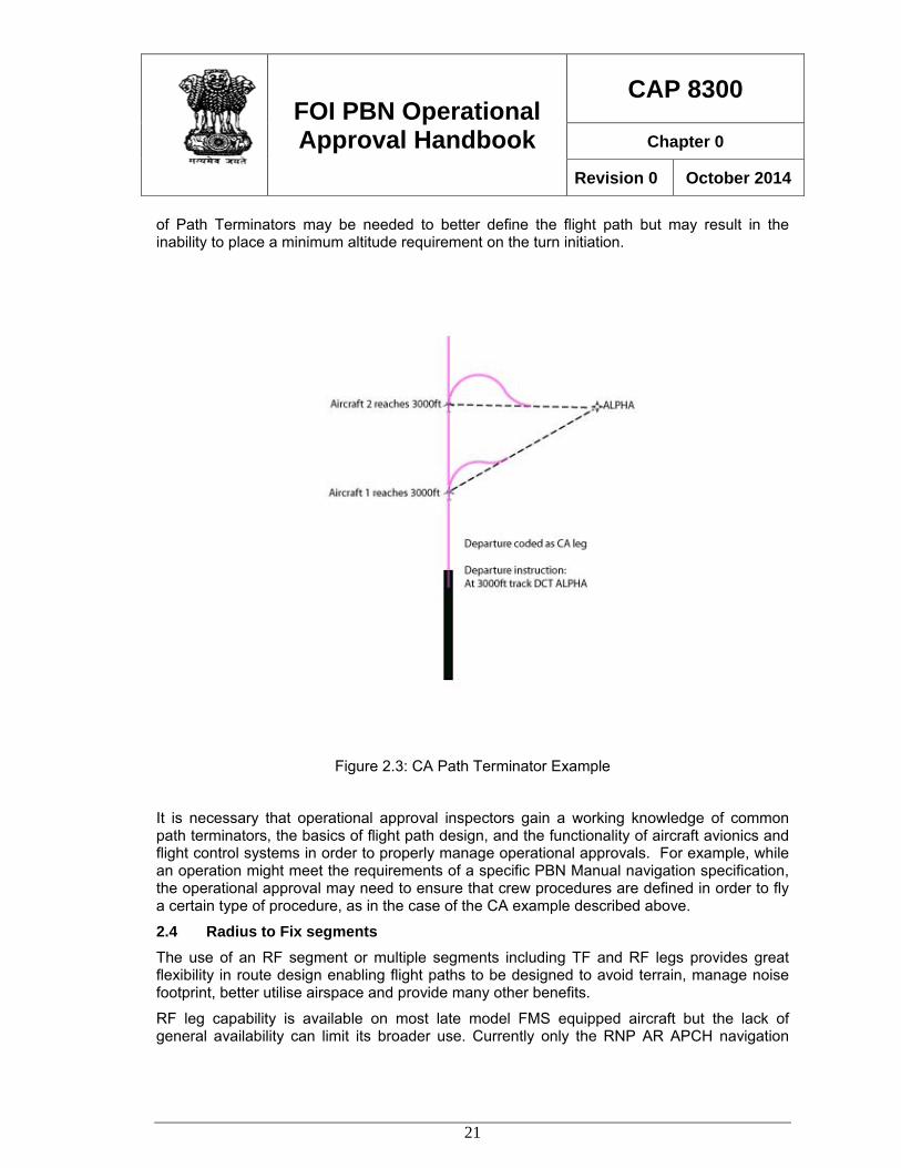
A CA or Course to Altitude leg defines a nominated course until a specified altitude is reached. On reaching the altitude the path is “terminated” and the avionics will follow the path defined by the next leg or path and terminator. The CA leg which is commonly used to specify the initial leg of a departure is not normally supported by general aviation GPS receivers, which are not usually integrated with the aircraft’s vertical navigation system. Consequently the flight planned departure route may not be followed and pilot intervention (manual selection of next leg) is required.
In the example in Figure 2.3 two aircraft are cleared on a departure with the same instruction. Depending on the climb performance, the position at which the aircraft reaches 3000ft and the CA leg is terminated will vary. If the aircraft is equipped with an integrated vertical navigation system the termination will be automatic and the active route will sequence to the next leg which may be (for example) a Direct to Fix (DF) leg.
If vertical navigation capability is not available, the termination must be initiated by the flight crew. For manually sequenced navigation systems the track to the next fix will depend on the point at which the direct to function is selected. In the example, the pilot has selected Direct To immediately on reaching 3000ft and the track is generated from that position. If Direct To is selected after the turn a different track will be displayed. In this and similar examples, the actual flight path is variable and may not meet operational requirements. A different sequence
FOI PBN Operational Approval Handbook
CAP 8300
Chapter 0
Revision 0 October 2014
21
of Path Terminators may be needed to better define the flight path but may result in the inability to place a minimum altitude requirement on the turn initiation.
Figure 2.3: CA Path Terminator Example
It is necessary that operational approval inspectors gain a working knowledge of common path terminators, the basics of flight path design, and the functionality of aircraft avionics and flight control systems in order to properly manage operational approvals. For example, while an operation might meet the requirements of a specific PBN Manual navigation specification, the operational approval may need to ensure that crew procedures are defined in order to fly a certain type of procedure, as in the case of the CA example described above.
2.4 Radius to Fix segments The use of an RF segment or multiple segments including TF and RF legs provides great flexibility in route design enabling flight paths to be designed to avoid terrain, manage noise footprint, better utilise airspace and provide many other benefits.
RF leg capability is available on most late model FMS equipped aircraft but the lack of general availability can limit its broader use. Currently only the RNP AR APCH navigation
FOI PBN Operational Approval Handbook
CAP 8300
Chapter 0
Revision 0 October 2014
22
specification supports the use of RF legs but it is expected that application will be extended in due course.
Capability for RF legs, while extremely useful, is not without limitation, and it is important that the FMS functionality, aircraft flight control logic, and the application of RF legs to flight procedure design are properly understood.
A segment coded as an RF leg creates a circular flight path over the surface of the earth, defined by a start and end point, a turn radius and an origin. ARINC 424 coded segments before and after the RF legs must join at a tangent to the circle defined by the RF leg. Consequently the sequence of legs used can be TF/RF or RF/TF and RF/RF. Joining of RF legs to other RF legs is acceptable and turn reversal and change of radius may occur. This capability allows great flexibility in design.
While complex flight paths can now be designed and displayed as the active route, the aircraft must have the capability to accurately follow the defined flight path. Pilots are familiar with flying turns at a constant airspeed and angle of bank which enables a circular flight path to be flown with reference to the air mass and are trained to manually compensate for the presence of wind if necessary. Pilots now need to understand that the FMS will fly an exact circular flight path over the ground and the angle of bank will be adjusted by the flight control system to maintain that circular flight path.
The physics of flight are such that the radius of a circle (over the ground) is limited by groundspeed and angle of bank. The minimum radius that can be flown is therefore limited by the maximum available bank angle, and the groundspeed.
Bank angle limits are determined by the aircraft manufacturer, and are also limited by crew selection, aircraft configuration and phase of flight. In normal approach/departure configuration a typical bank angle capability for modern jet transport aircraft is 30° but may be as low as 20°. The bank angle limit can be 8° or less at low altitude, and similarly bank angle limits are also applied at high altitude. The RNP AR APCH navigation specification requires aircraft to be capable of 25° angle of bank in normal circumstances and 8° below 400ft. The procedure designer uses these limits in the design of RF turns, and pilots need to be aware of the aircraft capability in all flight phases. Inspectors should familiarise themselves with aircraft capability documentation during the operational approval process, for aircraft that will utilise RF leg capability.
Groundspeed is a function of TAS, and consequently IAS, plus or minus the ambient tailwind or headwind component. In order to ensure that the flight path during an RF turn can be maintained under all normal weather conditions the procedure designer allows for a maximum tailwind component or “rare-normal” wind. The maximum tailwind component is selected from a wind model which is intended to represent the maximum winds likely to be encountered at various altitudes, generally increasing with altitude. A tailwind component of up to 100KT may be applied in some cases.
As groundspeed is also affected by TAS, the flight crew needs to manage the IAS within acceptable limits to ensure that the bank angle limits, and hence the ability to maintain the flight path, are not exceeded in circumstances where high winds exist. In normal routine operations, where ambient winds are generally light, quite low bank angles are sufficient to maintain RF turns of average radius. However, if the IAS is allowed to exceed normal limits,
the limleadin
Genernavigacases
Flight limitingproced
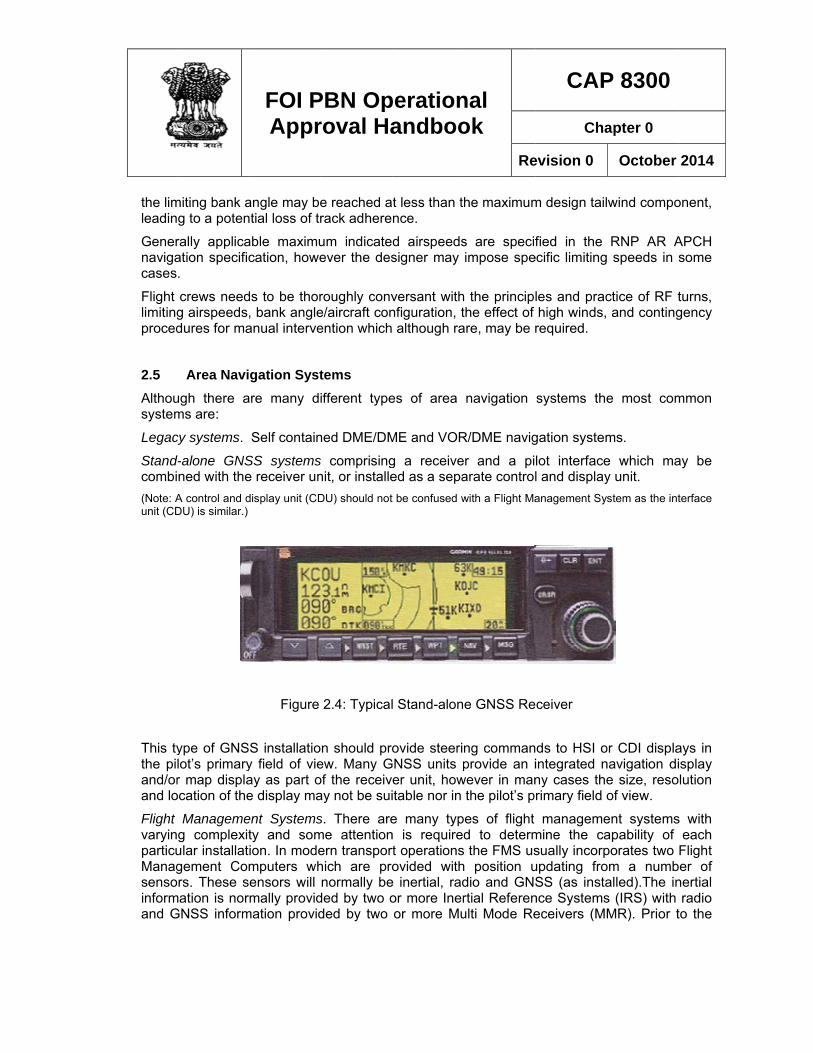
2.5 Althousystem
Legac
Stand-combi(Note: Aunit (CD
This tythe piland/orand lo
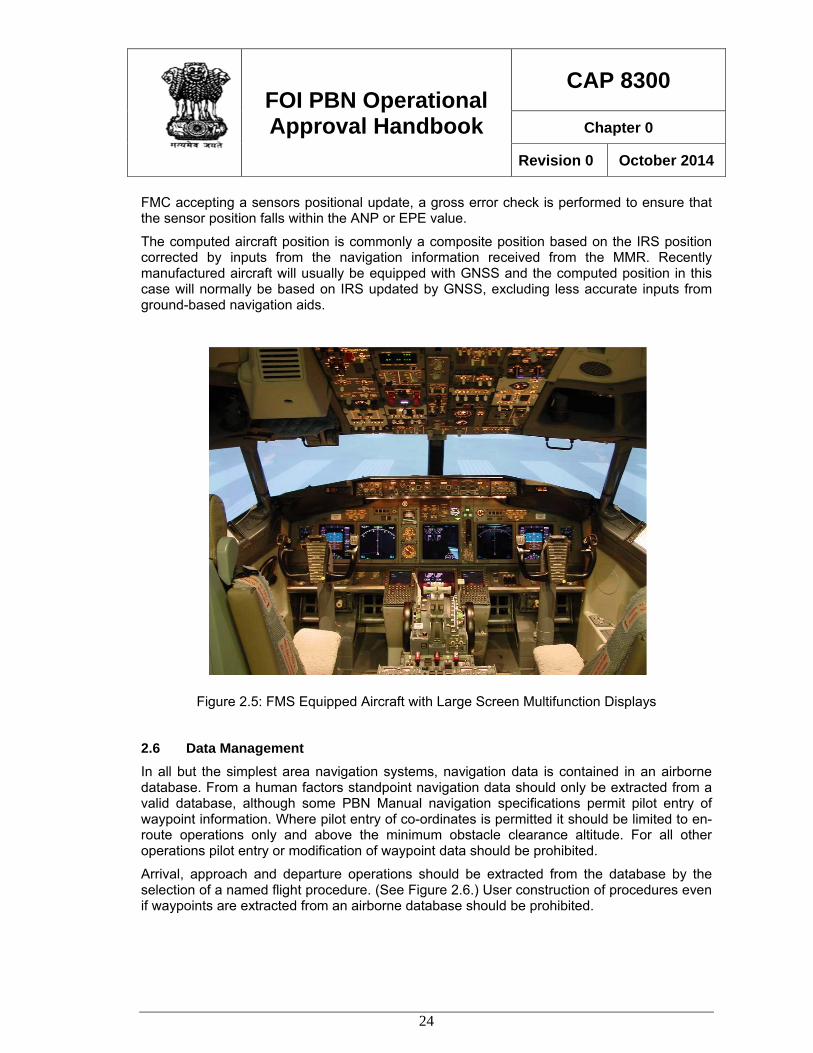
Flight varyinparticuManagsensoinformand G
miting bank ag to a poten
rally applicaation specific.
crews needg airspeeds,dures for ma
Area Naviugh there ams are:
cy systems.
-alone GNSned with theA control and dDU) is similar.)
ype of GNSlot’s primaryr map displa
ocation of the
Managemeg complexitular installatgement Comrs. These s
mation is norGNSS inform
FOI PAppr
angle may bential loss of tr
able maximucation, howe
ds to be thor, bank angleanual interve
gation Systare many di
Self contain
SS systemse receiver undisplay unit (CD
Figure
S installatioy field of vieay as part oe display ma
ent Systemsty and somion. In modemputers whensors will mally provid
mation provid
PBN Oproval Ha
e reached arack adhere
um indicateever the des
roughly conve/aircraft conention which
tems ifferent type
ned DME/DM
s comprisingnit, or installeDU) should not
2.4: Typical
n should proew. Many Gof the receivay not be sui
s. There areme attentionern transporhich are pronormally be
ded by two oded by two
perationandboo
t less than tnce.
d airspeedssigner may
versant withnfiguration, t although ra
es of area
ME and VOR
g a receiveed as a sepat be confused w
l Stand-alon
ovide steeriGNSS units p
er unit, howitable nor in
e many typn is requiredrt operationsovided with
e inertial, rador more Ineror more Mu
nal ok
Re
he maximum
s are specifimpose spe
h the principthe effect of are, may be r
navigation
R/DME navig
r and a piarate controlwith a Flight Ma
e GNSS Re
ng commanprovide an i
wever in manthe pilot’s p
es of flight d to determ
s the FMS ush position udio and GNSrtial Referenulti Mode Re
CAP
Cha
evision 0
m design tail
fied in the ecific limiting
les and prachigh winds,required.
systems the
gation system
lot interfacel and displayanagement Sy
ceiver
ds to HSI ointegrated nny cases therimary field o
managememine the casually incorpupdating froSS (as insta
nce Systemseceivers (MM
P 8300
apter 0
October
wind compo
RNP AR A speeds in
ctice of RF t and conting
e most com
ms.
e which may unit. stem as the int
or CDI displanavigation die size, resoof view.
ent systemsapability of porates two om a numballed).The ins (IRS) with MR). Prior t
2014
onent,
APCH some
turns, gency
mmon
ay be
terface
ays in isplay lution
s with each
Flight ber of nertial radio
to the
FOI PBN Operational Approval Handbook
CAP 8300
Chapter 0
Revision 0 October 2014
24
FMC accepting a sensors positional update, a gross error check is performed to ensure that the sensor position falls within the ANP or EPE value.
The computed aircraft position is commonly a composite position based on the IRS position corrected by inputs from the navigation information received from the MMR. Recently manufactured aircraft will usually be equipped with GNSS and the computed position in this case will normally be based on IRS updated by GNSS, excluding less accurate inputs from ground-based navigation aids.
Figure 2.5: FMS Equipped Aircraft with Large Screen Multifunction Displays
2.6 Data Management In all but the simplest area navigation systems, navigation data is contained in an airborne database. From a human factors standpoint navigation data should only be extracted from a valid database, although some PBN Manual navigation specifications permit pilot entry of waypoint information. Where pilot entry of co-ordinates is permitted it should be limited to en-route operations only and above the minimum obstacle clearance altitude. For all other operations pilot entry or modification of waypoint data should be prohibited.
Arrival, approach and departure operations should be extracted from the database by the selection of a named flight procedure. (See Figure 2.6.) User construction of procedures even if waypoints are extracted from an airborne database should be prohibited.
FOI PBN Operational Approval Handbook
CAP 8300
Chapter 0
Revision 0 October 2014
25
PBN operations are dependent upon valid navigation data. Unlike conventional navigation where the basic navigation guidance is originated from a physical point (e.g. a VOR transmitter) area navigation is totally dependent on electronic data and gross errors can occur due to erroneous data or mismanagement of valid data. In general PBN Manual navigation specifications require or recommend that data is obtained from an approved supplier who has implemented appropriate quality control procedures. Despite a data supplier meeting such quality control standards, there still remains a risk that invalid data may be contained in the airborne database and caution should be exercised. In the case of operations conducted where collision with terrain is a risk, (approach/departure) additional checks at each data update cycle are required. Electronic comparison of data against a controlled source is preferred, but manual or simulator checks may be used where this method is not available.
It should also be noted that whilst every precaution may be taken to ensure the validity of the airborne database, that valid data can in some circumstances be incorrectly interpreted and managed by the airborne navigation system. It is extremely difficult to protect against this type of problem, however in evaluating PBN operating procedures, due attention should be made to ensure that crew review procedures are appropriate and sufficient to constitute a last line of defence.
FOI PBN Operational Approval Handbook
CAP 8300
Chapter 0
Revision 0 October 2014
26
Chapter 3 NAVIGATION PERFORMANCE 3.1 General All navigation systems can be described in terms of performance. For example, a ground based navigation aid such as VOR delivers a measurable level of performance which is applied in terms of accepted navigational tolerances.
PBN operations are similarly based on navigation performance, but the concept of performance is fundamentally different. Whereas an operation based on a ground based navigation aid is dependent upon the performance of the radiated signal and the ability of an aircraft to accurately utilise that signal, in Performance Based Navigation the performance itself is specified and the navigation system is required to meet the minimum level of performance. In principle any method of navigation that achieves the specified level of navigation performance is acceptable. However, in practice a particular navigation system is required in some cases in order to meet the requirements of a particular navigation specification. For example RNP 4 requires the mandatory carriage of GNSS as no other current navigation system is available to meet the requirements of the navigation specification. In theory at least, if another means of navigation became available which met the performance requirements for RNP 4 without GNSS, then the requirement for GNSS could be removed from the navigation specification.
3.2 Performance Evaluation A navigation specification requires performance which is defined by a number representing the accuracy of the navigation system measured in nautical miles. Throughout the PBN manual, accuracy is specified as the probability that the computed position will be within the specified radius of the actual position 95% of the time. While this is the basis for the specification of the accuracy requirement, the achieved accuracy may be many times much better and this can be somewhat misleading.
FOI PBN Operational Approval Handbook
CAP 8300
Chapter 0
Revision 0 October 2014
27
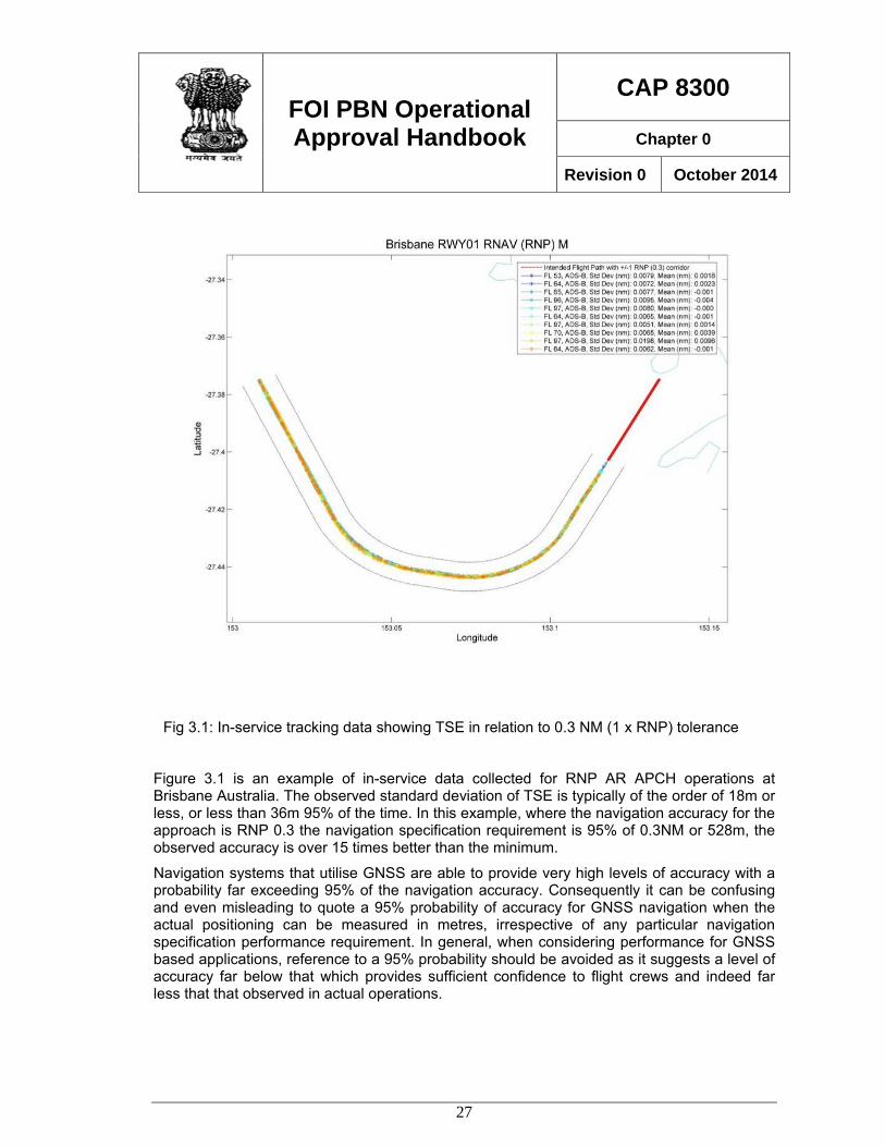
Figure 3.1 is an example of in-service data collected for RNP AR APCH operations at Brisbane Australia. The observed standard deviation of TSE is typically of the order of 18m or less, or less than 36m 95% of the time. In this example, where the navigation accuracy for the approach is RNP 0.3 the navigation specification requirement is 95% of 0.3NM or 528m, the observed accuracy is over 15 times better than the minimum.
Navigation systems that utilise GNSS are able to provide very high levels of accuracy with a probability far exceeding 95% of the navigation accuracy. Consequently it can be confusing and even misleading to quote a 95% probability of accuracy for GNSS navigation when the actual positioning can be measured in metres, irrespective of any particular navigation specification performance requirement. In general, when considering performance for GNSS based applications, reference to a 95% probability should be avoided as it suggests a level of accuracy far below that which provides sufficient confidence to flight crews and indeed far less that that observed in actual operations.
Fig 3.1: In-service tracking data showing TSE in relation to 0.3 NM (1 x RNP) tolerance
FOI PBN Operational Approval Handbook
CAP 8300
Chapter 0
Revision 0 October 2014
28
Accuracy is only one of a number of considerations when evaluating performance and the overall capability of the navigation system, including cockpit displays, flight control systems and other factors are considered in determining the aircraft’s navigation performance capability.
The computation of navigation performance is normally carried out by the aircraft manufacturer, and in many cases the manufacturer will provide a statement in the AFM giving the computed capability. However the basis upon which performance is computed varies between manufacturers and in some cases the methodology differs between aircraft types from the same manufacturer.
In most cases the manufacturer’s published navigation performance was computed some years prior to the publication of the PBN Manual and other relevant State RNAV/RNP guidance. Consequently the operational approval must consider the circumstances in which the manufacturer computed the navigation performance, and the role (if any) of the regulatory authority in accepting the manufacturer’s claims. In many cases, the regulatory authority has “accepted” the manufacturer’s calculations there being no available standard available at the time of initial certification against which the performance statement could be “approved”.
Following publication of the PBN manual and similar State PBN documentation some manufacturers have demonstrated aircraft navigation capability against those published requirements and such aircraft can be accepted as meeting the specified performance without further evaluation. It is expected that in due course many manufacturers will demonstrate compliance with PBN Manual requirements, and this will reduce the workload associated with operational approval.
Other aircraft will require evaluation in order to determine that the required level of performance is consistent with the operational approval. The applicant should be asked to provide substantiation of the aircraft navigation performance supported by manufacturer documentation.
3.3 Performance Components Navigation performance is computed by considering the following components:
Navigation System Error (NSE). Sometimes called PEE or Position Estimation Error, this value represents the capability of the navigation avionics to determine position, relative to the aircraft’s actual position. NSE is dependent on the accuracy of the inputs to the position solution, such as the accepted accuracy of DME or GNSS measurements.
Flight Technical Error (FTE). Also referred to as Path Steering Error, this value represents the ability of the aircraft guidance system to follow the computed flight path. FTE is normally evaluated by the aircraft manufacturer based on flight trials, although in cases where the manufacturer is not able to provide adequate data the operator may need to collect in-service data. FTE values will usually vary for a particular aircraft depending on the flight control method, and for example, a lower FTE may be applicable to operations where the autopilot is coupled compared to the FTE for manual flight using flight director. This variation may in turn lead to different overall performance values depending on the method of control.
Path Definition Error (PDE). An area navigation route is defined by segments between waypoints. The definition of the path therefore is dependent on the resolution of the waypoint, and the ability of the navigation system to manage the waypoint data. However, as waypoints
FOI PBN Operational Approval Handbook
CAP 8300
Chapter 0
Revision 0 October 2014
29
can be defined very accurately, and a high level of accuracy is able to be managed by most navigation systems this error is minimal and is generally considered to be zero.
Total System Error (TSE) is computed as the statistical sum of the component errors. An accepted method of computing the sum of a number of independent statistical measurements is to compute the square root of the sum of the squares of the component values, or the Root Sum Square (RSS) method.
The computation for accuracy is:
222 PDEFTENSETSE ++=
As discussed PDE is normally considered to be zero and can be ignored.
No measurement can be absolute and some error or variation will always occur. Therefore errors are normally stated in terms of the probability that the specified accuracy is achieved. For example, the FTE might be described as +/- (X) NM / 95%.
In the general PBN Manual case where accuracy is specified as the 95% value, then the 95% TSE is calculated for the 95% values for NSE and TSE.
The risk that an aircraft capable of a particular navigation performance (95%) will exceed a specified navigation tolerance can then be estimated for any desired probability. It is convenient and reasonably reliable to consider that navigation errors are “normally distributed” and are represented by a Gaussian distribution. A Gaussian or Normal distribution is a representation of the probable errors that may be expected for many common random events. If the probability of a particular event is known, (e.g. 95% TSE) then using a Gaussian distribution the estimated error for another probability can also be calculated.
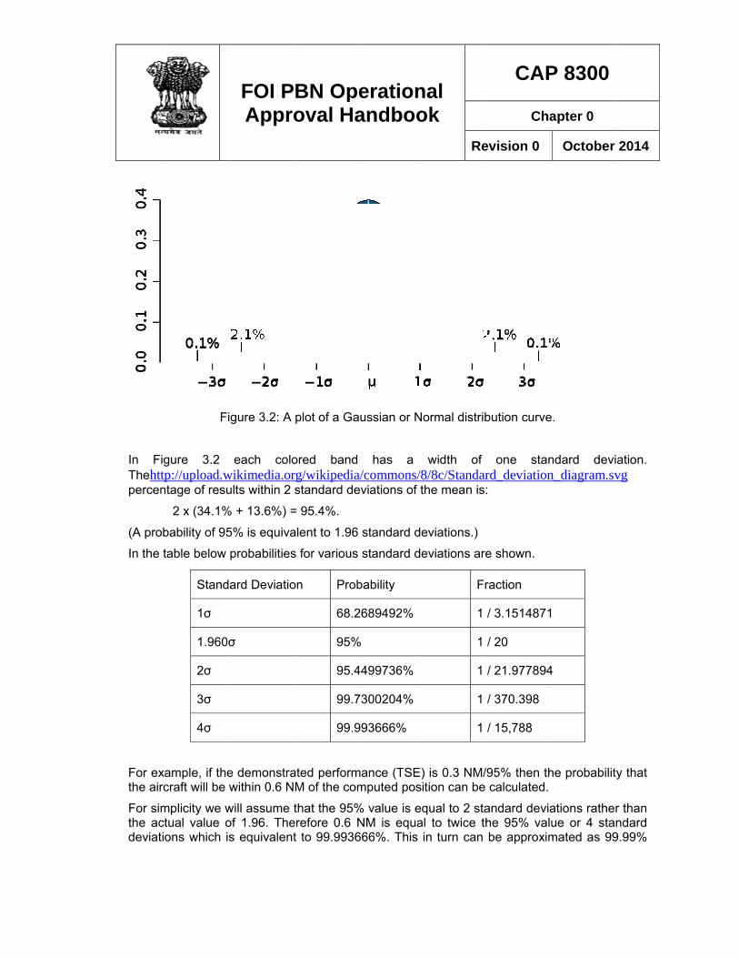
Standard deviation is a widely used measure of the variability or dispersion. In simple terms, it shows how much variation there is from the "average" (mean). It may be thought of as the average difference of the scores from the mean of distribution, how far they are away from the mean. A low standard deviation indicates that the data points tend to be very close to the mean, whereas high standard deviation indicates that the data are spread out over a large range of values.
In FiThehttpercen
(A pro
In the
For exthe air
For simthe acdeviat
F
igure 3.2 tp://upload.wntage of resu
2 x (34.1%
obability of 95
table below
xample, if thrcraft will be
mplicity we wctual value oions which
Stand
1σ
1.960
2σ
3σ
4σ
FOI PAppr
Figure 3.2: A
each colowikimedia.orults within 2
% + 13.6%) =
5% is equiva
probabilities
e demonstrawithin 0.6 N
will assume of 1.96. Theis equivalen
dard Deviatio
0σ
PBN Oproval Ha
plot of a Ga
ored bandrg/wikipediastandard de
= 95.4%.
alent to 1.96
s for various
ated performNM of the co
that the 95%erefore 0.6 nt to 99.9936
on Pro
68.2
95%
95.4
99.7
99.9
perationandboo
aussian or N
d has a a/commons/8eviations of t
6 standard de
s standard de
mance (TSE)mputed pos
% value is eNM is equa666%. This
bability
2689492%
%
4499736%
7300204%
993666%
nal ok
Re
Normal distrib
width of 8/8c/Standarthe mean is:
eviations.)
eviations are
) is 0.3 NM/ition can be
qual to 2 staal to twice thin turn can
Fr
1
1
1
1
1
CAP
Cha
evision 0
bution curve
one stanrd_deviation:
e shown.
95% then thcalculated.
andard deviahe 95% valube approxim
raction
/ 3.1514871
/ 20
/ 21.977894
/ 370.398
/ 15,788
P 8300
apter 0
October
.
ndard devin_diagram.sv
he probability
ations ratherue or 4 stanmated as 99
4
2014
ation. vg
y that
r than ndard 9.99%
FOI PBN Operational Approval Handbook
CAP 8300
Chapter 0
Revision 0 October 2014
31
which indicates at only .01% of all computed positions will be greater than 0.6NM. For convenience, .01% can be described as 1 in 10,000 or 1 x 10⁻⁴.
3.4 Required Navigation Performance RNP is a means of specifying the performance for a particular type of operation. In order to meet a particular performance level a number of requirements must be met.
Accuracy Position accuracy can be defined as the probability that the computed position will be within a specified distance of the actual position. This performance measure assumes that the reliability of the computation (i.e. the system is operating within its specification without fault), and we have seen in the previous section how this can be computed.
Integrity For aviation purposes which are safety critical we must be assured that the navigation system can be trusted. Even though we may be satisfied as to the accuracy of the determination of position, we must also ensure that the computation is based on valid or “trusted” information. Various methods (e.g. RAIM) are used to protect the position solution against the possibility of invalid position measurements.
Availability means that the system is usable when required. For GNSS operations, unless augmented, availability is high but normally less than 100%. Operational means are commonly needed to manage this limitation.
Continuity refers to the probability that a loss of service will occur whilst in use.
For RNP operations the navigation system must meet accuracy and integrity requirements but operational procedures may be used to overcome limitations in availability and continuity. In addition to the four performance parameters RNP also requires on-board performance monitoring and alerting.
In practice, RNP capability is determined by the most limiting of the characteristics listed above.
As discussed, in the general case RNP is based on GNSS. The position accuracy for GNSS is excellent and can support operations with low RNP. The lowest current RNP in use is RNP 0.10, although considering position accuracy alone, GNSS would be able to support lower RNP.
However it will be recalled that accuracy is also dependent on FTE and this component is by far the dominant factor. Consequently, the RNP capability of GNSS equipped aircraft is dependent not on navigation system accuracy, but the ability for the aircraft to follow the defined path. FTE is commonly determined by the ability of the aircraft flight control system, and the lowest FTE values are commonly achieved with auto-pilot coupled.
A further consideration is the requirement for on-board performance monitoring and alerting. For GNSS systems, navigation system performance monitoring and alerting is automatic. Except in some specific installations, FTE monitoring and alerting is a crew responsibility, and the ability of the crew to perform this function depends on the quality of information displayed to the crew.
While an aircraft may be capable of a particular RNP capability, it is not always necessary or desirable that the full capability is applied. In addition to the consideration of accuracy and
FOI PBN Operational Approval Handbook
CAP 8300
Chapter 0
Revision 0 October 2014
32
performance monitoring, the operation must always be protected against invalid positioning information, i.e. integrity is required.
In order to support low RNP operations, an appropriate level of integrity protection is necessary. The lower the RNP type, the greater level of integrity protection is required, which in turn reduces the availability and continuity of the service. Consequently a trade-off needs to be made between the RNP selected and availability.
PBN Manual Navigation specifications are based on a level of navigation performance appropriate to the intended purpose, rather than the inherent capability of the navigation system. For example a GNSS equipped aircraft has very high positioning accuracy, and if flown using autopilot exhibits low FTE, however for terminal SID/STAR operations, RNP 1 is adequate for the intended purpose, resulting in virtually 100% availability, and reduced crew workload in FTE performance monitoring.
3.5 Performance Limitations The overall system performance is limited by the most constraining case. For DME/DME systems the most constraining condition is likely to be accuracy, and the positioning is dependent upon measurements which are limited by the accuracy of DME.
Systems which use GNSS as the primary means of position fixing are inherently extremely accurate, and the navigation system accuracy is independent of the navigation application. i.e. the underlying positioning accuracy is the same for RNP 10 as it is for RNP 0.10.
GNSS system performance is normally dependent on FTE and in particular the capability for
monitoring and alerting of FTE. In the performance formula 222 PDEFTENSETSE ++= NSE is small, PDE is considered negligible and FTE becomes the dominant contributor.
FTE is normally dependent upon the capability of the flight control system (A/P or FD) to maintain the desired flight path, and commonly varies with phase of flight. In climb, decent and cruise, the sensitivity of flight control systems is normally less than in the approach phase for obvious reasons.
Despite the capability of the flight control system to achieve low FTE values, RNP also requires that the flight crew is able to monitor cross-track error and provide an alert if deviation limits are exceeded (normally achieved by flight crew procedures). In many cases, the cockpit display of cross-track error limits the crew’s ability to monitor cross-track error, irrespective of the demonstrated FTE, and this may limit the RNP performance. Some aircraft AFMs contain statements of RNP performance which are valid when the accuracy of the flight control system alone is considered, but it may be difficult to justify the same performance when the display of cross-track deviation is taken into consideration.
GNSS integrity monitoring consistent with the manufacturer’s stated RNP performance is normally provided and is seldom a limitation on overall RNP capability. In practice, however, the satellite system may not be capable of supporting the full aircraft RNP capability, and the available RNP capability can be limited by the satellite constellation.
In Europe, for RNP AR APCH, RNP performance also considers the effect of non-normal events, and different RNP performance may be stated depending on the operational circumstances. Typically differing RNP values will be published for all engines operating and one engine inoperative cases. ICAO approach procedure design does not consider non-
FOI PBN Operational Approval Handbook
CAP 8300
Chapter 0
Revision 0 October 2014
33
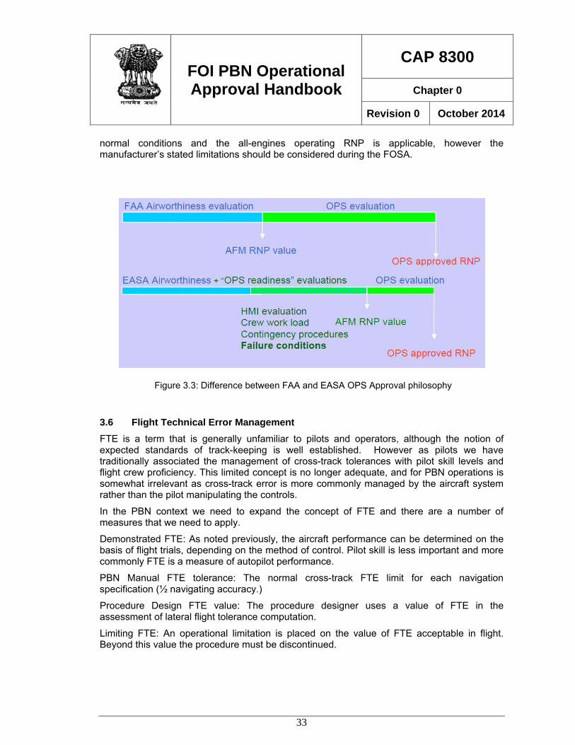
normal conditions and the all-engines operating RNP is applicable, however the manufacturer’s stated limitations should be considered during the FOSA.
3.6 Flight Technical Error Management FTE is a term that is generally unfamiliar to pilots and operators, although the notion of expected standards of track-keeping is well established. However as pilots we have traditionally associated the management of cross-track tolerances with pilot skill levels and flight crew proficiency. This limited concept is no longer adequate, and for PBN operations is somewhat irrelevant as cross-track error is more commonly managed by the aircraft system rather than the pilot manipulating the controls.
In the PBN context we need to expand the concept of FTE and there are a number of measures that we need to apply.
Demonstrated FTE: As noted previously, the aircraft performance can be determined on the basis of flight trials, depending on the method of control. Pilot skill is less important and more commonly FTE is a measure of autopilot performance.
PBN Manual FTE tolerance: The normal cross-track FTE limit for each navigation specification (½ navigating accuracy.)
Procedure Design FTE value: The procedure designer uses a value of FTE in the assessment of lateral flight tolerance computation.
Limiting FTE: An operational limitation is placed on the value of FTE acceptable in flight. Beyond this value the procedure must be discontinued.
Figure 3.3: Difference between FAA and EASA OPS Approval philosophy
FOI PBN Operational Approval Handbook
CAP 8300
Chapter 0
Revision 0 October 2014
34
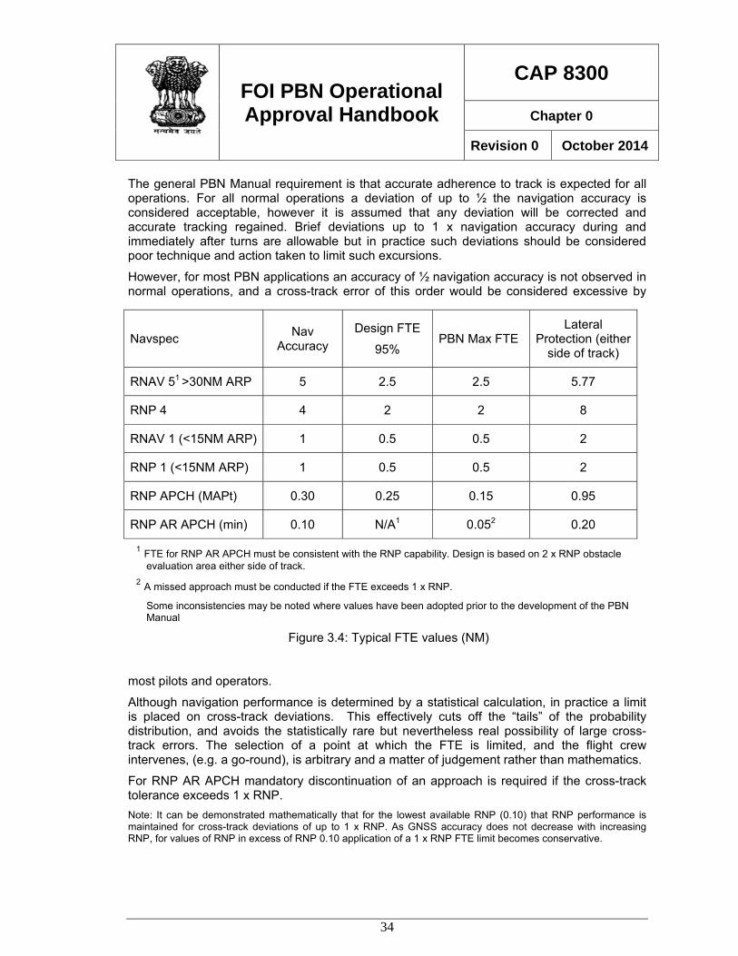
The general PBN Manual requirement is that accurate adherence to track is expected for all operations. For all normal operations a deviation of up to ½ the navigation accuracy is considered acceptable, however it is assumed that any deviation will be corrected and accurate tracking regained. Brief deviations up to 1 x navigation accuracy during and immediately after turns are allowable but in practice such deviations should be considered poor technique and action taken to limit such excursions.
However, for most PBN applications an accuracy of ½ navigation accuracy is not observed in normal operations, and a cross-track error of this order would be considered excessive by
most pilots and operators.
Although navigation performance is determined by a statistical calculation, in practice a limit is placed on cross-track deviations. This effectively cuts off the “tails” of the probability distribution, and avoids the statistically rare but nevertheless real possibility of large cross-track errors. The selection of a point at which the FTE is limited, and the flight crew intervenes, (e.g. a go-round), is arbitrary and a matter of judgement rather than mathematics.
For RNP AR APCH mandatory discontinuation of an approach is required if the cross-track tolerance exceeds 1 x RNP. Note: It can be demonstrated mathematically that for the lowest available RNP (0.10) that RNP performance is maintained for cross-track deviations of up to 1 x RNP. As GNSS accuracy does not decrease with increasing RNP, for values of RNP in excess of RNP 0.10 application of a 1 x RNP FTE limit becomes conservative.
Navspec Nav Accuracy
Design FTE 95%
PBN Max FTE Lateral
Protection (either side of track)
RNAV 51 >30NM ARP 5 2.5 2.5 5.77
RNP 4 4 2 2 8
RNAV 1 (<15NM ARP) 1 0.5 0.5 2
RNP 1 (<15NM ARP) 1 0.5 0.5 2
RNP APCH (MAPt) 0.30 0.25 0.15 0.95
RNP AR APCH (min) 0.10 N/A1 0.052 0.20
1 FTE for RNP AR APCH must be consistent with the RNP capability. Design is based on 2 x RNP obstacle evaluation area either side of track.
2 A missed approach must be conducted if the FTE exceeds 1 x RNP.
Some inconsistencies may be noted where values have been adopted prior to the development of the PBN Manual
Figure 3.4: Typical FTE values (NM)
FOI PBN Operational Approval Handbook
CAP 8300
Chapter 0
Revision 0 October 2014
35
However, for RNP APCH the PBN Manual requirement implies a mandatory go-round at ½ navigation accuracy. The design FTE for RNP APCH (0.25NM on final) is the value used in the development of RNAV (GNSS) design criteria prior to the development of the PBN Manual, and was based on manual piloting tolerances using stand-alone GNSS equipment and a 0.3NM CDI scaling. For FMS equipped aircraft, a go-round requirement of ½ navigation accuracy limit may be impractical in many aircraft. A more general view exists that immediate recovery action should be taken when a deviation exceeds ½ navigation accuracy and a go-round conducted if the deviation exceeds 1 x RNP (0.3).
The validity of the performance capability calculation, or the design of the procedures, is not in question as the normal achieved FTE is likely to be extremely small. The issue is merely what indication of a cross-track error as a trigger for discontinuation is acceptable, and in some cases this may be higher than preferred. The safety of the operation and the confidence in the navigating accuracy is in no way compromised, but the operating procedures may need to recognise the limitations of the display of cross-track information, and reasonable instructions provided to the crew regarding the point at which action should be taken.
Training should emphasise that for all PBN operations accurate adherence to track is required. A misconception exists that for en-route operations, where the navigation accuracy is relatively large (RNP 10, RNP 4, RNAV 5) that unauthorised off-track deviations up to the navigation accuracy are acceptable without ATC approval. Pilots need to understand that aircraft separation standards are based on the statistical FTE probability assuming that the aircraft follows the defined track as closely as possible. Inspectors should take care to ensure that training programs provide proper guidance on the management of FTE.
3.7 Lateral Deviation Monitoring The monitoring of FTE requires that suitable information is displayed to the flight crew indicating any deviation from the lateral or (for VNAV) vertical path. The PBN Manual includes some guidance on the use of a “lateral deviation indicator” or other means such as flight director or autopilot to manage FTE but in practice some judgement on the part of inspectors is required in order to asses that the information displayed to the flight crew is adequate for a particular application.
No difficulty should be experienced with aircraft equipped with stand-alone GNSS receivers which should be installed to provide a display of cross-track information on a CDI or HSI. Normal TSO C129a and TSO C146a functionality provides automatic full-scale deflection scaling appropriate to the phase of flight, and provided the flight crew is properly trained in the operation of the receiver, suitable indications of cross-track deviations will be available.
Unfortunately FMS equipped aircraft are generally not equipped with a course deviation indicator when operated in an RNAV mode and this type of installation will require evaluation during the approval process.
Although it is not possible to generalize, and there is some variation between manufacturers, in this type of aircraft the Navigation Display (ND) is commonly used to indicate the aircraft position relative to the flight planned path. As it is common practice to operate with autopilot engaged, track adherence is generally good and manufacturers have historically not taken the view that the indication of cross-track error either by the use of a CDI-type graphical indicator, or a numerical indication on the ND is of importance.
FOI PBN Operational Approval Handbook
CAP 8300
Chapter 0
Revision 0 October 2014
36
With the development of RNAV approach operations, where accurate track adherence is of significance, the suitability of displays has become a topic of interest.
Typical sources of cross-track information in production aircraft include:
Navigation (MAP) Display – Graphical indications. Graphical indication of track deviation relative to the flight planned track. Depending on the selected map scale, the size of the aircraft symbol can be used to estimate the cross-track deviation. This type of indication is sufficient to allow reasonable estimation, depending on the map scale selected and the aircraft symbol, of deviations as small as 0.1NM. For operations where the cross-track tolerance is relatively large, (RNAV 10, RNAV 5, RNP 4, and RNAV 1 or RNP 1) this may be considered adequate. This type of indication, although limited, is available in the pilot’s forward field of view and in this regard contributes to satisfying some of the basic requirements for track monitoring.
Navigation (MAP) Display - Numeric indications. In addition to a graphical display of position relative to flight planned track, many manufacturers also provide a digital indication of cross-track deviation on the ND. Commonly this is limited to one decimal place e.g. 0.1, 0.2, 0.3 NM. Some aircraft apply a rounding to the display of digital cross-track deviation. For example, in at least one case, the display of deviation is not indicated until the deviation reaches 0.15NM, and then a rounded value of 0.2NM is displayed. In this case the initial digital indication to the crew is 0.2NM which is displayed when the actual deviation is 0.15NM. Similarly, as the XTK deviation reduces the last digital indication shown is 0.10NM which occurs when the actual deviation is 0.15NM. Increasingly manufacturers are offering as either standard or as a customer option, digital indications to 2 decimal places e.g. .01, .02, .03 NM. Two digital place cross-track deviation indication is becoming the industry standard and operators should be encouraged to select this option if available. Unfortunately on older aircraft this is often not available due to software or display limitations.
Control and Display Unit Numeric Display Many systems display a numeric indication of cross-track and/or vertical deviation on the CDU (MCDU). In cases where the ND does not provide a numeric display, an initial graphical indication of deviation may be supplemented by a cross-reference to the appropriate CDU page to obtain a numeric indication. Numeric indications may be one or two decimal places. The disadvantage of this indication is that it is not in the primary field of view. When CDU indications are taken into account in the evaluation of the adequacy of cockpit track monitoring, the crew procedures need also to be evaluated. A procedure needs to be in place such that at least one member of the crew (normally the PNF/PM) has the appropriate CDU page displayed during the operation and there is a system of cross-checking and crew callouts in place.
Primary Flight Display (PFD) CDI displays A number of manufacturers are now offering either as standard or as a customer option, the display of cross-track deviation on the PFD in a manner similar to the display used for ILS. A different symbol is used to identify that the information is RNAV rather than LOC. Implementations vary from relatively simple fixed scale displays to more sophisticated displays which provide an estimate of “available” cross-track tolerance based on the current estimate of navigation performance.
3.8 Vertical Deviation Monitoring Many VNAV indicators have been installed to provide relatively coarse indications of vertical path adherence, intended to provide adequate monitoring for en-route climb/descent and
FOI PBN Operational Approval Handbook
CAP 8300
Chapter 0
Revision 0 October 2014
37
cruise operations. Commonly this type of display was not intended for use on approach operations where a resolution of as low as 10ft is expected. The size of the display may be quite small and the full scale indication can be a much as +/-400ft. More commonly a vertical deviation indicator, similar to an ILS glide slope indicator is provided on the PFD. Numeric indications of vertical deviation may also be available on the CDU.
3.9 Evaluation of Deviation Displays While each case must be evaluated some broad guidelines can be applied.
Consideration must be given to the means of flight control. Where AP or FD is the means of flight control, lateral and vertical deviations can be expected to be small, and displays sufficient only for adequate monitoring of performance are necessary.
1. The display of information is be related to the required navigation tolerance. For en-route and terminal operations, a lesser standard, such as a graphical or basic numeric XTK indication is normally adequate.
2. For RNP APCH operations, the final approach tolerance is stated to be ½ the navigation tolerance i.e. 0.15NM. Consequently indication of small XTK deviation is necessary. The use of a graphical (MAP) display and a digital XTK indication either on the ND or CDU is generally adequate, provided the flight control method (AP or FD) and crew monitoring procedures are appropriate.
3. For VNAV approach operations a PFD indicator is normally the minimum requirement, although an alternative means might be assessed as adequate provided the crew can readily identify vertical track deviations sufficient to limit the flight path within the required tolerances (- 50ft or 75ft and +100ft)
4. For RNP AR APCH operations not less than RNP 0.3, the same tracking accuracy as for RNP APCH applies and a similar standard of display is generally adequate. A CDI indication on the PFD while preferred is not essential, as is the display of 2 digit numerical XTK deviation on the ND. Flight control using AP or FD is normally used and adequate procedures should be in place for the crew to manage cross-track error.
5. For RNP AR APCH operations less than RNP 0.3 the generally accepted standard is a graphical display of XTK on the PFD and a numeric display to two decimal places on the ND.
In assessing the displays and procedures for monitoring of XTE consideration should also be given functions such as flight path prediction, vertical situation displays, HUGS etc., It should also be noted that the manufacturer’s statement of RNP capability is dependent on the method of flight control, which determines the statistical value of FTE used in the demonstration of RNP capability. Some manufacturers and/or regulatory authorities require a minimum standard of cockpit displays for RNP AR APCH operations.
FOI PBN Operational Approval Handbook
CAP 8300
Chapter 0
Revision 0 October 2014
38
Chapter 4 GNSS 4.1 General The advent of satellite based navigation provides significant improvement in navigation performance which is available to aircraft of all types. While Performance Based Navigation in general is not dependent upon satellite navigation the benefits available within the PBN concept are multiplied by the use of GNSS.
It is not within the scope of this Handbook to cover the basics of GNSS navigation and it is assumed that readers have or will obtain knowledge and training in satellite based navigation principles and practice.
The discussion of satellite navigation will be related to specific elements of satellite based navigation that are relevant to PBN operational approvals.
GNSS systems range from stand-alone receivers, now in general use in general aviation and commuter airline applications, to Flight Management Systems incorporating IRS systems updated by GNSS. Whatever the installation, the navigation capability of GNSS is excellent, and there is little variation in the positioning accuracy across the various types of installation. However there are considerable differences in functionality, cockpit displays, integrity monitoring, alerting and other characteristics that must be considered in the operational approval, depending upon the particular navigation specification.

FOI PBN Operational Approval Handbook
CAP 8300
Chapter 0
Revision 0 October 2014
39
FOI PBN Operational Approval Handbook
CAP 8300
Chapter 0
Revision 0 October 2014
40
4.2 Monitoring and alerting An IFR GNSS navigation receiver incorporates by design a system to monitor the positioning performance and to provide an alert to the operating crew when the minimum requirements appropriate to the desired navigation performance is not available. Consequently a GNSS navigation system qualifies as an RNP navigation system as it is able to provide the necessary on board performance monitoring and alerting functions. However, the monitoring and alerting function of the navigation system alone is insufficient for RNP applications, and FTE must also be monitored. A number of aircraft equipped with GNSS fail to meet the monitoring requirements for RNP because of a lack of capability for the crew to monitor cross-track deviation.
Prior to the PBN Manual, many operations utilising GNSS were classified as RNAV operations, such as RNAV (GNSS) approach procedures. In order to be consistent with the PBN Manual definition of RNP, RNAV (GNSS) procedures are now classified as RNP APCH procedures, as they fulfil the on-board performance monitoring and alerting requirements associated with RNP systems.
4.3 GNSS Accuracy The positioning accuracy of GNSS signal in space is dependent upon the satellite constellation and is generally independent of the aircraft systems. Positioning accuracy is excellent and a significant amount of data has now been accumulated which demonstrates that unaugmented GNSS is able to provide accuracy measured in metres with a high degree of availability over much of the earth’s surface.
Whilst PBN Manual navigation specifications may contain an accuracy requirement specified as a 95% probability, when GNSS is used, the underlying accuracy is independent of the navigation specification requirement. An aircraft equipped with GNSS and approved for operations at a particular RNP level e.g. RNP 0.3 is capable of no less accurate navigation when operating to another navigation specification such as RNP 1.
It should be recognised that when GNSS is available navigation position accuracy remains high irrespective of the particular operation. However it should also be noted that accuracy is only one consideration in regard to a PBN operation and other factors may limit the approved operational capability.
4.4 Integrity Monitoring All IFR lateral navigation systems, both conventional and performance based, are required to meet standards for integrity. Integrity represents the trust that we place in the ability of the system to provide navigation information that is not misleading. Whilst a navigation system may provide accurate guidance, in aviation we require assurance that the guidance is valid under all reasonable circumstances and various means have been implemented to provide that assurance.
Integrity for conventional navigation aids is indicated by the absence of a warning flag on a VOR or ILS indicator, or the presence of the Morse ident when using an ADF. For GNSS systems a loss of integrity availability is indicated by an annunciation (in various forms) displayed to the flight crew.
FOI PBN Operational Approval Handbook
CAP 8300
Chapter 0
Revision 0 October 2014
41
GNSS systems employ a variety of methods to monitor the integrity of the navigation solution, the most basic being Receiver Autonomous Integrity Monitoring or RAIM. This type of monitoring system is generally associated with (but not limited to) stand-alone general aviation receivers. Other types of integrity monitoring include proprietary hybrid systems which integrate inertial navigation with GNSS positioning to provide high levels of availability of navigation with integrity.
Unfortunately the term RAIM is erroneously used to describe integrity systems in general, and this can lead to some misconceptions of the role and application of integrity monitoring to performance based navigation.
4.5 Fault Detection Integrity and accuracy are both required for valid GNSS navigation. However accuracy and integrity, although in some ways related, are entirely different parameters and should not be confused.
The GNSS receiver, GNSS satellites, ground monitoring and control stations all contribute to providing a valid navigation system and each element incorporates fault detection protection. A GNSS receiver continuously monitors the computed position and will detect and annunciate a fault if the position solution is not within defined limits.
However, the ability of a GNSS receiver to detect a fault is limited by the extremely low GNSS signal strength. GNSS satellites radiate a low power signal from some 20,000 km in space which reduces in inverse proportion to the square of the distance. The usable signal is therefore very weak and below the general ambient signal noise level. Normally a fault will be detected despite the low signal strength; however in rare circumstances the ability to detect a fault can be limited by the noise level, constellation geometry and other factors and for commercial aviation applications a means is necessary to protect the user against the unlikely but nevertheless real possibility that a fault might not be detected.
RAIM uses a mathematical solution to protect against this rare condition. The receiver calculates in real time a parameter called Horizontal Protection Level (HPL), in order to protect the navigation solution against a potential navigation fault.
4.6 Horizontal Protection Level HPL is the radius of a circle in the horizontal plane, with its centre being at the true position, such that the probability that an indicated position being outside the circle but not detected is less than 1 in 1000. That is the receiver calculates a level of protection currently available based on the geometry of the satellite constellation. As the position of the satellites in view is constantly changing HPL also continually changes.
HPL is a parameter as the name suggests designed to provide integrity protection rather than error detection. Unfortunately it is a common misconception that the actual position “floats” anywhere within the HPL radius. The actual navigation solution, as evidenced by a substantial body of observations over many years, remains very accurate. The function of HPL is to protect the navigation solution against the possibility that in the unlikely event that a satellite ranging error should occur that the risk of a missed detection is reduced to an acceptable probability.
FOI PBN Operational Approval Handbook
CAP 8300
Chapter 0
Revision 0 October 2014
42
In normal circumstances, should a satellite ranging error occur which results in an out-of tolerance solution, the GNSS system will detect the fault and provide an alert to the user. The problem is that we cannot be certain that the fault detection system will always work, and as discussed, due the ambient noise level, under certain circumstances, a fault could be missed. So if we can’t be 100% sure about the detection system, something else must be done, and that’s where RAIM and HPL (or an equivalent protection system) comes in.
The way this is done is to program the receiver to calculate in real time, based on the actual satellite geometry, a worst case scenario which provides an acceptable level of confidence that if a real fault was to occur it would be detected. Note that we are not talking about detecting a fault right now, but rather that we are protecting a region around the indicated position, just in case a fault should happen at any time in the future. That potential fault many never occur, but we can be confident that if it did that we are protected.
HPL provides for a number of “worst case” circumstances. As GPS position is a triangulation of pseudo-range measurements from satellites, any ranging error from one of those satellites has the potential to result in an inaccurate solution. A failure in the US GPS satellite system is any ranging error greater than 150m, however as any position solution is a computation dependent on a number of range measurements the ranging error would need to be significantly greater to be a problem. In addition the HPL computation assumes that only the “worst” satellite fails, when in reality any one of the satellites used in the position solution has equal probability of failure. The “worst” satellite would be one lower to the horizon as any ranging error will bias the lateral position more than a satellite which is closer to overhead.
Depending on the date at which the receiver was manufactured, the HPL calculation may also assume that Selective Availability is still active. Consequently when conducting RNP operations observers may note differing “performance” displayed in the cockpit between aircraft operating in the same position and time, where SA is assumed active in the HPL calculated by one aircraft and not active in another. This effect also has a bearing on RNP availability prediction results.
Consequently there is some in-built conservatism in the computation of HPL.
For each phase of flight the maximum acceptable HPL is limited by a Horizontal Alarm Limit (HAL). For stand-alone GPS receivers, the HAL for each phase of flight is fixed (0.3 approach, 1.0 terminal. 2.0 en-route). For other navigation systems, the limit can be selected by database or crew input. For example, in an aircraft where the RNP is selectable, changing the RNP (in general) has the effect of changing the limiting HPL, but this selection has no effect on the accuracy of the position.
From an operational approval perspective, it important to understand that the GNSS position solution is very accurate, and that the aircraft position is reliably defined by the very small navigation system error and the relatively large flight technical error. Consequently operational considerations should be based on the acknowledged accurate and reliable guidance available, rather than the misconception that the actual position is randomly located within the area that is defined about the intended flight path that we protect. For example, when operating procedures rely on the alignment of an RNP approach with the landing runway, we can be confident that the aircraft will reliably be on track.
FOI PBN Operational Approval Handbook
CAP 8300
Chapter 0
Revision 0 October 2014
43
At the same time we must also understand that despite the observed accuracy, that it is necessary to provide an area of “protection” around the aircraft flight path, so that if at some time whether in the next 30 seconds or 30years a satellite ranging fault of sufficient magnitude was to occur, that the aircraft will be within the protected area, or a fault annunciated.
Integrity is our insurance policy and we do not operate without it in IFR aviation. But just as in day-to-day life although we make sure our policy is paid up we do not run our lives based on our insurance policies.
4.7 Integrity Alerting For aviation applications, it is accepted that integrity is essential and therefore operations are predicated on the availability of an integrity monitoring system, and the absence of an alert. However, as discussed above the computed HPL will vary depending upon the geometry of the constellation and the maximum value of HPL is determined by the HAL appropriate to the particular operation. If the number of satellites in view is reduced, or the position of satellites is poor then the ability to detect a potential fault reduces and the computed HPL consequently increases. If, for example, for the particular phase of flight, the computed HPL exceeds the HAL, then the required level integrity is determined to be not available, and an alert is generated. Note: The condition HPL <HAL is only one example of a limiting integrity condition. There are a number of systems which provide equal or better integrity monitoring which may not depend on HPL.
Alerts vary depending upon the type of system, aircraft and avionics manufacturer, but typical alerts are:
• RAIM NOT AVBL
• LOSS OF INTEGRITY
• UNABLE REQD NAV PERFORMANCE RNP
• GPS PRIMARY LOST
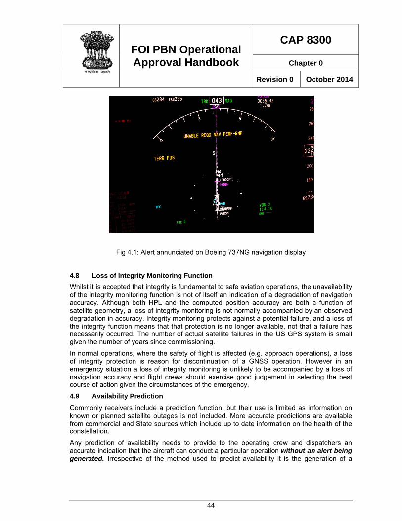
FOI PBN Operational Approval Handbook
CAP 8300
Chapter 0
Revision 0 October 2014
44
Fig 4.1: Alert annunciated on Boeing 737NG navigation display
4.8 Loss of Integrity Monitoring Function Whilst it is accepted that integrity is fundamental to safe aviation operations, the unavailability of the integrity monitoring function is not of itself an indication of a degradation of navigation accuracy. Although both HPL and the computed position accuracy are both a function of satellite geometry, a loss of integrity monitoring is not normally accompanied by an observed degradation in accuracy. Integrity monitoring protects against a potential failure, and a loss of the integrity function means that that protection is no longer available, not that a failure has necessarily occurred. The number of actual satellite failures in the US GPS system is small given the number of years since commissioning.
In normal operations, where the safety of flight is affected (e.g. approach operations), a loss of integrity protection is reason for discontinuation of a GNSS operation. However in an emergency situation a loss of integrity monitoring is unlikely to be accompanied by a loss of navigation accuracy and flight crews should exercise good judgement in selecting the best course of action given the circumstances of the emergency.
4.9 Availability Prediction Commonly receivers include a prediction function, but their use is limited as information on known or planned satellite outages is not included. More accurate predictions are available from commercial and State sources which include up to date information on the health of the constellation.
Any prediction of availability needs to provide to the operating crew and dispatchers an accurate indication that the aircraft can conduct a particular operation without an alert being generated. Irrespective of the method used to predict availability it is the generation of a
FOI PBN Operational Approval Handbook
CAP 8300
Chapter 0
Revision 0 October 2014
45
cockpit warning that precludes the successful completion of an operation. Therefore it is advantageous to ensure that the prediction method represents the aircraft alerting system as closely as possible.
The computation of availability is complicated by the variations in the methods used to provide integrity protection. For basic stand-alone GNSS receivers, alerting limits are fixed (e.g. HPL < 0.3 in approach mode), but for other installations integrity alerting is based on more complex analysis and/or more sophisticated integrity monitoring systems. Consequently for accurate integrity protection availability prediction the actual technique applicable to the particular aircraft and navigation equipment must be applied. For RNP AR APCH operations, where a number of lines of RNP minima may be available, availability prediction needs to be related to the various levels of RNP.
The prediction of the availability of a navigation service with integrity is useful as it permits the flight crew or dispatcher to take into account the probability of a loss of service and plan an alternative course of action such as delay, rescheduling or selection of an alternative means of navigation.
In some RNP systems, the required level of performance is able to be maintained for some time after the loss of the GNSS signal, (normally with IRS coasting) and an alert is not annunciated until the performance is computed to have reached the relevant limit. Advanced hybrid (IRS/GNSS) integrity monitoring systems are able to provide GNSS position with integrity for long periods (e.g. 45 minutes) after a loss of the GNSS signal.
4.10 Augmentation systems The majority of Performance Based Navigation operations are able to be conducted using an unaugmented GNSS signal is space. The general GNSS signal is sometimes referred to as an Aircraft Based Augmentation System (ABAS) although this may lead to the misconception that some correction is made to the basic GNSS signal.
The currently available augmentation systems rely on either Ground-Based augmentation (GBAS) or Satellite Based augmentation (SBAS). GBAS relies on an array of receivers located close to the area of operations and supports operations such as GLS (GBAS Landing System). In the United States GBAS is referred to as the Local Area Augmentation system or LAAS. None of the PBN Manual operations currently depend upon GBAS.
SBAS, which is represented in the United States by the Wide Area Augmentation System, employs additional geo-stationary satellites and a network of ground-based reference stations, in North America and Hawaii, to measure small variations in the GPS satellites' signals in the western hemisphere. Measurements from the reference stations are routed to master stations, which queue the received Deviation Correction (DC) and send the correction messages to geostationary WAAS satellites in a timely manner (every 5 seconds or better). Those satellites broadcast the correction messages back to Earth, where WAAS-enabled GPS receivers use the corrections while computing their positions to improve accuracy and integrity.
An SBAS system is capable of supporting all navigation specifications requiring GNSS. In addition an SBAS system provides capability for Satellite based APV approach procedures which are classified in terms of the PBN Manual as a type of RNP APCH operations. This
FOI PBN Operational Approval Handbook
CAP 8300
Chapter 0
Revision 0 October 2014
46
type of approach operation is referred to as Localiser Performance with Vertical guidance or LPV and provided ILS-like guidance to a DA of not lower than 200ft.
LPV operations are designed to be compatible with existing flight guidance installations and provide lateral and vertical course guidance which varies in sensitivity with distance from the runway, much like an ILS.
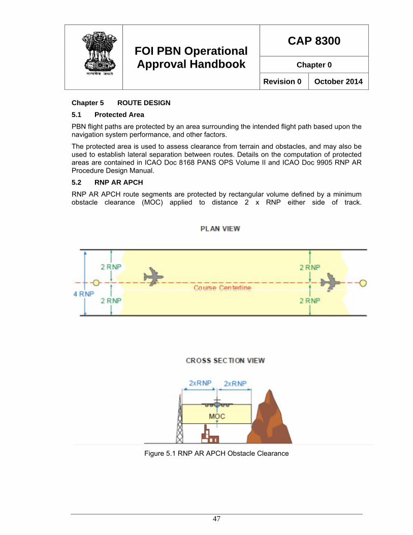
FOI PBN Operational Approval Handbook
CAP 8300
Chapter 0
Revision 0 October 2014
47
Chapter 5 ROUTE DESIGN 5.1 Protected Area PBN flight paths are protected by an area surrounding the intended flight path based upon the navigation system performance, and other factors.
The protected area is used to assess clearance from terrain and obstacles, and may also be used to establish lateral separation between routes. Details on the computation of protected areas are contained in ICAO Doc 8168 PANS OPS Volume II and ICAO Doc 9905 RNP AR Procedure Design Manual.
5.2 RNP AR APCH RNP AR APCH route segments are protected by rectangular volume defined by a minimum obstacle clearance (MOC) applied to distance 2 x RNP either side of track.
Figure 5.1 RNP AR APCH Obstacle Clearance
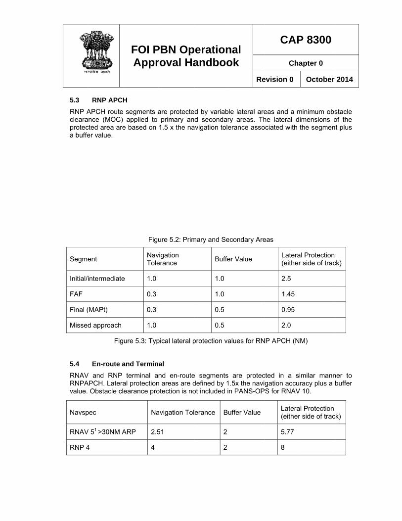
5.3 RNP Aclearaproteca buffe
Segme
Initial/
FAF
Final (
Missed
5.4 RNAVRNPAvalue.
Navsp
RNAV
RNP 4
RNP APCHAPCH route
ance (MOC) cted area areer value.
ent
intermediate
(MAPt)
d approach
Fig
En-route aV and RNP APCH. Latera
Obstacle cl
pec
V 51 >30NM A
4
FOI PAppr
H segments aapplied to
e based on
Figu
NavTole
e 1.0
0.3
0.3
1.0
ure 5.3: Typ
and Terminterminal a
al protectionearance pro
Na
ARP 2.5
4
PBN Oproval Ha
are protecteprimary an
1.5 x the na
ure 5.2: Prim
vigation erance
pical lateral p
al nd en-route
n areas are dotection is no
avigation Tol
51
perationandboo
ed by variabld secondar
avigation tole
mary and Se
Buffe
1.0
1.0
0.5
0.5
protection va
e segments defined by 1ot included in
lerance Bu
2
2
nal ok
Re
le lateral arery areas. Therance asso
condary Are
er Value
alues for RN
are protec.5x the navin PANS-OP
uffer Value
CAP
Cha
evision 0
eas and a mhe lateral diociated with t
eas
Latera(either
2.5
1.45
0.95
2.0
NP APCH (N
cted in a sigation accurS for RNAV
Latera(either
5.77
8
P 8300
apter 0
October
minimum obsimensions othe segmen
al Protection r side of trac
M)
imilar mannracy plus a b10.
l Protection r side of trac
2014
stacle of the t plus
ck)
ner to buffer
k)
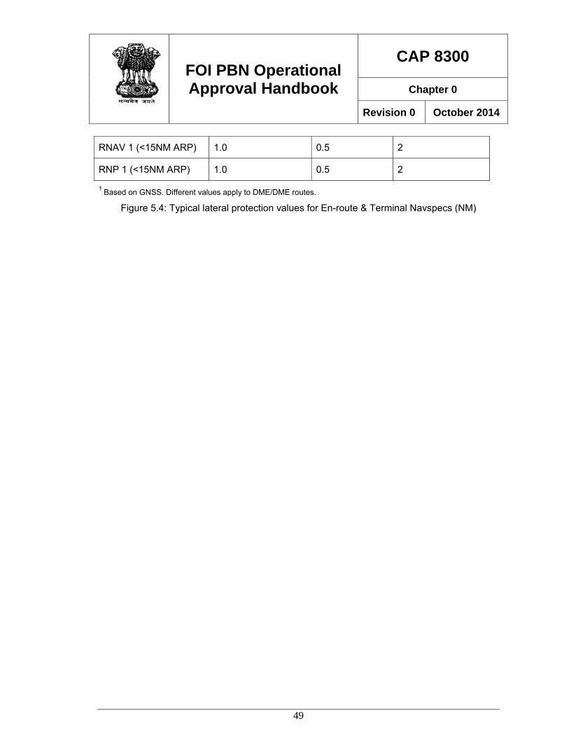
FOI PBN Operational Approval Handbook
CAP 8300
Chapter 0
Revision 0 October 2014
49
1 Based on GNSS. Different values apply to DME/DME routes.
Figure 5.4: Typical lateral protection values for En-route & Terminal Navspecs (NM)
RNAV 1 (<15NM ARP) 1.0 0.5 2
RNP 1 (<15NM ARP) 1.0 0.5 2
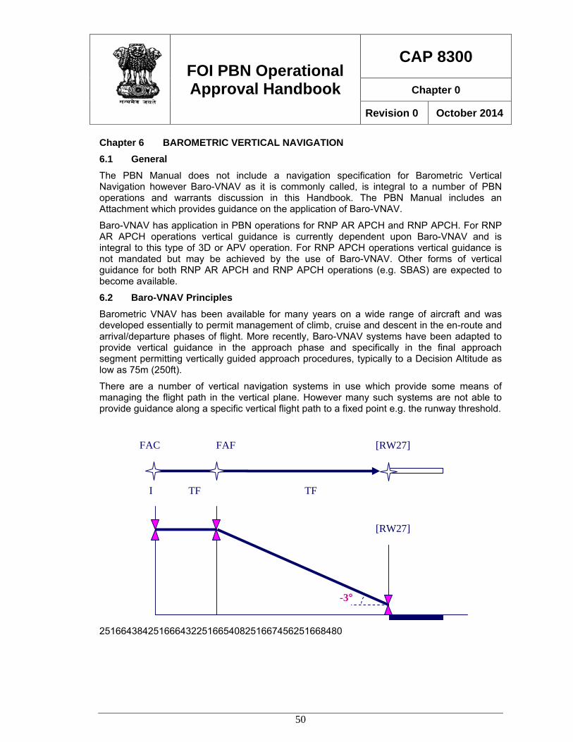
FOI PBN Operational Approval Handbook
CAP 8300
Chapter 0
Revision 0 October 2014
50
Chapter 6 BAROMETRIC VERTICAL NAVIGATION 6.1 General The PBN Manual does not include a navigation specification for Barometric Vertical Navigation however Baro-VNAV as it is commonly called, is integral to a number of PBN operations and warrants discussion in this Handbook. The PBN Manual includes an Attachment which provides guidance on the application of Baro-VNAV.
Baro-VNAV has application in PBN operations for RNP AR APCH and RNP APCH. For RNP AR APCH operations vertical guidance is currently dependent upon Baro-VNAV and is integral to this type of 3D or APV operation. For RNP APCH operations vertical guidance is not mandated but may be achieved by the use of Baro-VNAV. Other forms of vertical guidance for both RNP AR APCH and RNP APCH operations (e.g. SBAS) are expected to become available.
6.2 Baro-VNAV Principles Barometric VNAV has been available for many years on a wide range of aircraft and was developed essentially to permit management of climb, cruise and descent in the en-route and arrival/departure phases of flight. More recently, Baro-VNAV systems have been adapted to provide vertical guidance in the approach phase and specifically in the final approach segment permitting vertically guided approach procedures, typically to a Decision Altitude as low as 75m (250ft).
There are a number of vertical navigation systems in use which provide some means of managing the flight path in the vertical plane. However many such systems are not able to provide guidance along a specific vertical flight path to a fixed point e.g. the runway threshold.
251664384251666432251665408251667456251668480
[RW27]
[RW27]
-3°
FAFFAC
I TF TF
FOI PBN Operational Approval Handbook
CAP 8300
Chapter 0
Revision 0 October 2014
51
Figure 6.1: Construction of Vertical Flight Path
For Baro VNAV approach operations, the following elements are required:
• an area navigation system to enable distance to be determined to a waypoint which is the origin of the vertical flight path;
• the vertical flight path angle from the origin waypoint (normally the runway threshold) coded in the navigation database’
• a barometric air data system of sufficient accuracy;
• a flight guidance system able to provide vertical steering commands;
• cockpit control and monitoring displays.
Based on the distance to the origin of the vertical flight path, and the specified vertical flight path angle, the FMS computes the required height above the runway threshold or touchdown point and provides data to the aircraft flight guidance system and cockpit displays.
Although in some respects a baro VNAV guided approach procedure is similar to an ILS in operation, a fundamental difference is that the actual vertical flight path is dependent upon measurement of air density which changes with ambient conditions. Consequently the actual vertical flight path will vary depending on the surrounding air mass conditions and the specified vertical flight path angle is relevant only to ISA conditions. In anything other than ISA conditions the actual flight path angle will be higher or lower than designed.
Temperature is the major factor and in temperatures above ISA the actual flight path will be steeper than coded, and conversely below ISA temperatures will result in a lower flight path. Temperatures below ISA are therefore of concern because the clearance above terrain or obstacles will be reduced. Above ISA temperatures result in a steeper flight path which may lead to energy management issues. Temperature variations will also in lack of correlation of the barometric vertical flight path with fixed vertical flight path guidance provided by visual flight path guidance (VASIS) and ILS. Flight crew training must include a study of barometric
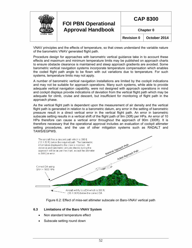
FOI PBN Operational Approval Handbook
CAP 8300
Chapter 0
Revision 0 October 2014
52
VNAV principles and the effects of temperature, so that crews understand the variable nature of the barometric VNAV generated flight path.
Procedure design for approaches with barometric vertical guidance take in to account these effects and maximum and minimum temperature limits may be published on approach charts to ensure obstacle clearance is maintained and steep approach gradients are avoided. Some barometric vertical navigation systems incorporate temperature compensation which enables the coded flight path angle to be flown with out variations due to temperature. For such systems, temperature limits may not apply.
A number of barometric vertical navigation installations are limited by the cockpit indications and may not be suitable for approach operations. Many such systems, while able to provide adequate vertical navigation capability, were not designed with approach operations in mind and cockpit displays provide indications of deviation from the vertical flight path which may be adequate for climb, cruise and descent, but insufficient for monitoring of flight path in the approach phase.
As the vertical flight path is dependent upon the measurement of air density and the vertical flight path is generated in relation to a barometric datum, any error in the setting of barometric pressure result in a direct vertical error in the vertical flight path. An error in barometric subscale setting results in a vertical shift of the flight path of 9m (30ft) per HPa. An error of 10 HPa therefore can cause a vertical error throughout the approach of 90m (300ft). It is therefore necessary that the operational approval includes an evaluation of cockpit altimeter setting procedures, and the use of other mitigation systems such as RADALT and TAWS/EGPWS.
Figure 6.2: Effect of miss-set altimeter subscale on Baro-VNAV vertical path
6.3 Limitations of the Baro VNAV System
• Non standard temperature effect
• Subscale setting round down
FOI PBN Operational Approval Handbook
CAP 8300
Chapter 0
Revision 0 October 2014
53
• Miss set altimeter subscale
Non standard temperature effect. During ISA atmospheric conditions the altimeter will read correctly and cause the aircraft to fly along the design or nominal profile. If the temperature is above ISA the altimeter will under read causing the aircraft to fly an actual profile which is above the nominal profile. The altimeter error is in the order of 4% per each 10 degrees of ISA deviation times the height above the airport reference datum. As the altimeter error is related to height above the airport datum the vertical offset reduces as the aircraft nears the threshold. Typically on an ISA +20 day the aircraft will be 20 feet above the nominal profile at 250 feet reducing to only 4 feet at the threshold.
Similarly, for each 15º difference from ISA, the VPA will vary by approximately 0.2º. i.e. on an ISA + 15 day the actual flight path angle for a 3º nominal VPA will be 3.2º. Consequently, of the average operating conditions differ significantly from ISA conditions it is useful to use VPA which will result in an actual VPA in the most common conditions. In the case above, a design VPA of 2.8º would result in an actual VPA close to 3º in average operating conditions.
If the atmosphere is below ISA the effect is reversed with the aircraft below the nominal profile by the same amounts. It should be noted that this temperature effect is apparent on all approach which use barometric altimetry to derive a profile. Inspectors should consider that whilst this effect is not new, increased visibility of this effect should be considered during training where Baro VNAV is intended to be deployed.
Crews must understand this effect and be aware that a lack of harmonisation with visual approach slope aids may occur, and indeed should be anticipated in temperatures which are non-standard.
Subscale setting round down. Air navigation service providers generally round subscale setting down. This has the effect of causing altimeters to under read causing the aircraft to fly above and parallel to the nominal profile. The effect is small but most pronounced when operating in HPA. If the tower read out is 1017.9 hPa the aerodrome QNH will be reported as 1017. This will cause an above nominal path offset of 27 feet. Inspectors should consider that whilst this effect is unlikely and small, increased visibility of this effect must be considered during training where Baro VNAV is intended to be deployed.
Miss-set altimeter subscale. Altimeter subscales can be miss-set for a variety of reasons. The effect has been previously discussed. It is important to remember that this issue is not unique to Baro VNAV operations. Any approach which relies on barometric information for profile will be affected by a miss-set altimeter subscale.
Depending on the aircraft equipment, there are a number of mitigators that contribute to reducing the risks associated with miss-set altimeter subscale. Inspectors must consider the following mitigators when evaluating baro VNAV operations and flight crew training.
Barometric VNAV Mitigators Procedural Mitigators:
FOI PBN Operational Approval Handbook
CAP 8300
Chapter 0
Revision 0 October 2014
54
• Independent crew check when recording destination altimeter subscale setting.
• Effective crew procedures for setting local altimeter subscale setting at transition level.
Electronic Mitigators:
• Electronic alerting if altimeter subscale setting is not reset at transition.
• Electronic alerting of altimeter differences.
• Terrain Awareness System (TAWS) which incorporates terrain clearance floors along with an accurate terrain model for the intended destination.
• Effective crew procedures in support of the TAWS alerts.
6.4 Aircraft Capability Baro-VNAV systems in common use have normally been approved in accordance with airworthiness requirements that were developed prior to the application of Baro VNAV systems to approach operations. For example compliance with FAA AC 20-129 Airworthiness Approval of Vertical Navigation (VNAV) Systems for use in the U.S. National Airspace system (NAS) and Alaska is commonly used as the basis for the operational approval of Baro VNAV operations. The vertical navigation accuracy values for the VNAV system, flight technical error and altimetry contained in such documentation may not be considered sufficient to adequately demonstrate the required level of capability, and operational approval may need to take into account other data, operating procedures or other mitigations.
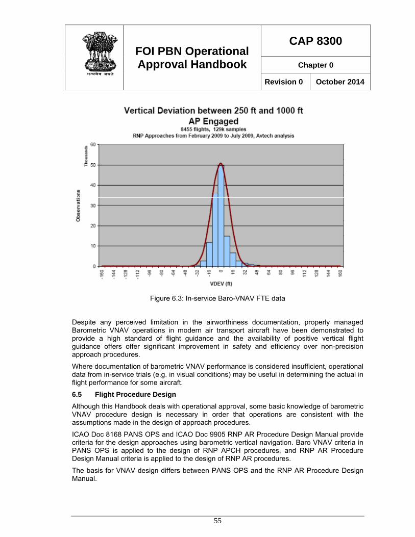
FOI PBN Operational Approval Handbook
CAP 8300
Chapter 0
Revision 0 October 2014
55
Figure 6.3: In-service Baro-VNAV FTE data
Despite any perceived limitation in the airworthiness documentation, properly managed Barometric VNAV operations in modern air transport aircraft have been demonstrated to provide a high standard of flight guidance and the availability of positive vertical flight guidance offers offer significant improvement in safety and efficiency over non-precision approach procedures.
Where documentation of barometric VNAV performance is considered insufficient, operational data from in-service trials (e.g. in visual conditions) may be useful in determining the actual in flight performance for some aircraft.
6.5 Flight Procedure Design Although this Handbook deals with operational approval, some basic knowledge of barometric VNAV procedure design is necessary in order that operations are consistent with the assumptions made in the design of approach procedures.
ICAO Doc 8168 PANS OPS and ICAO Doc 9905 RNP AR Procedure Design Manual provide criteria for the design approaches using barometric vertical navigation. Baro VNAV criteria in PANS OPS is applied to the design of RNP APCH procedures, and RNP AR Procedure Design Manual criteria is applied to the design of RNP AR procedures.
The basis for VNAV design differs between PANS OPS and the RNP AR Procedure Design Manual.
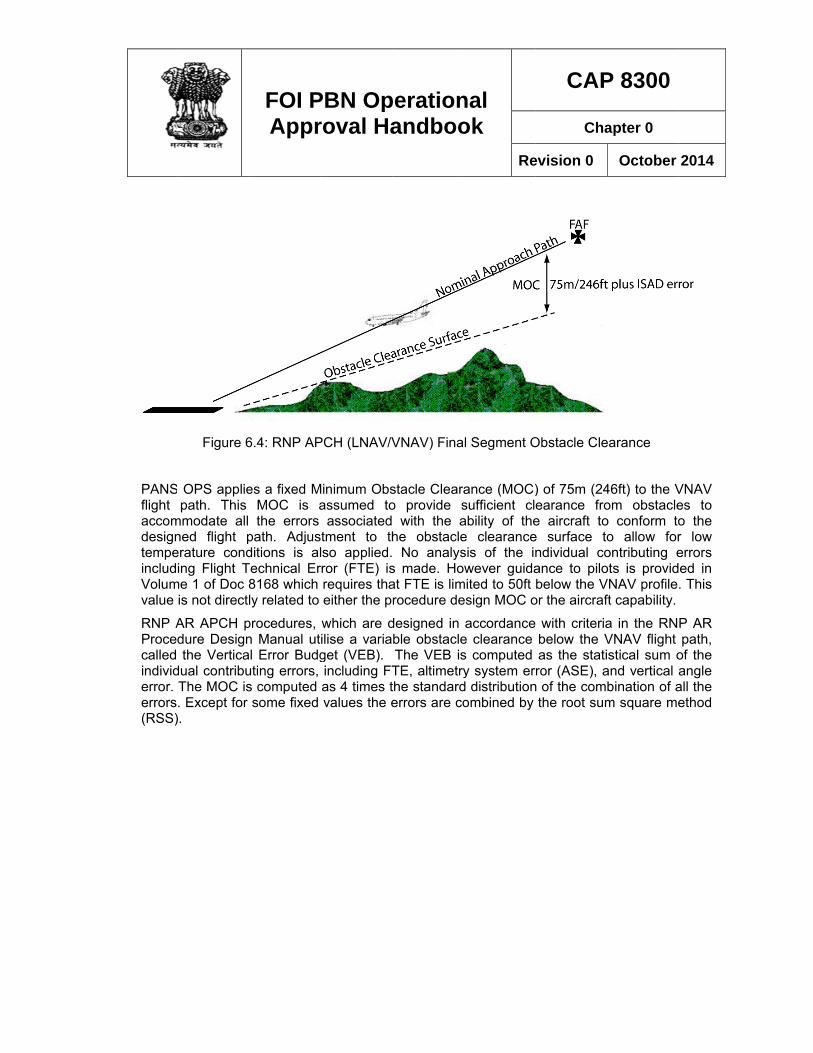
PANSflight accomdesigntempeincludVolumvalue
RNP AProcedcalled individerror. errors(RSS)
Figure 6
OPS appliepath. This
mmodate all ned flight perature conding Flight T
me 1 of Doc 8is not directl
AR APCH pdure Designthe Vertica
dual contribuThe MOC is. Except for ).
FOI PAppr
6.4: RNP AP
es a fixed MMOC is athe errors
path. Adjusditions is alTechnical Er8168 which ly related to
procedures, n Manual utl Error Budg
uting errors, s computed some fixed
PBN Oproval Ha
PCH (LNAV/V
Minimum Obsassumed to
associatedtment to thlso applied.rror (FTE) isrequires thaeither the p
which are dilise a variaget (VEB). including FTas 4 times tvalues the e
perationandboo
VNAV) Fina
stacle Clearao provide s with the ahe obstacle No analys
s made. Hoat FTE is limrocedure de
designed in ble obstacleThe VEB isTE, altimetrythe standarderrors are co
nal ok
Re
l Segment O
ance (MOC)sufficient clability of thee clearancesis of the inwever guida
mited to 50ft esign MOC o
accordancee clearance s computed y system er
d distributionombined by
CAP
Cha
evision 0
Obstacle Cle
) of 75m (24earance froe aircraft toe surface tondividual coance to pilobelow the V
or the aircraf
with criteriabelow the Vas the statiror (ASE), a
n of the comthe root sum
P 8300
apter 0
October
earance
46ft) to the Vom obstacleo conform too allow forontributing eots is providVNAV profileft capability.
a in the RNVNAV flight stical sum o
and vertical bination of am square me
2014
VNAV es to o the r low errors ed in . This
P AR path,
of the angle all the ethod
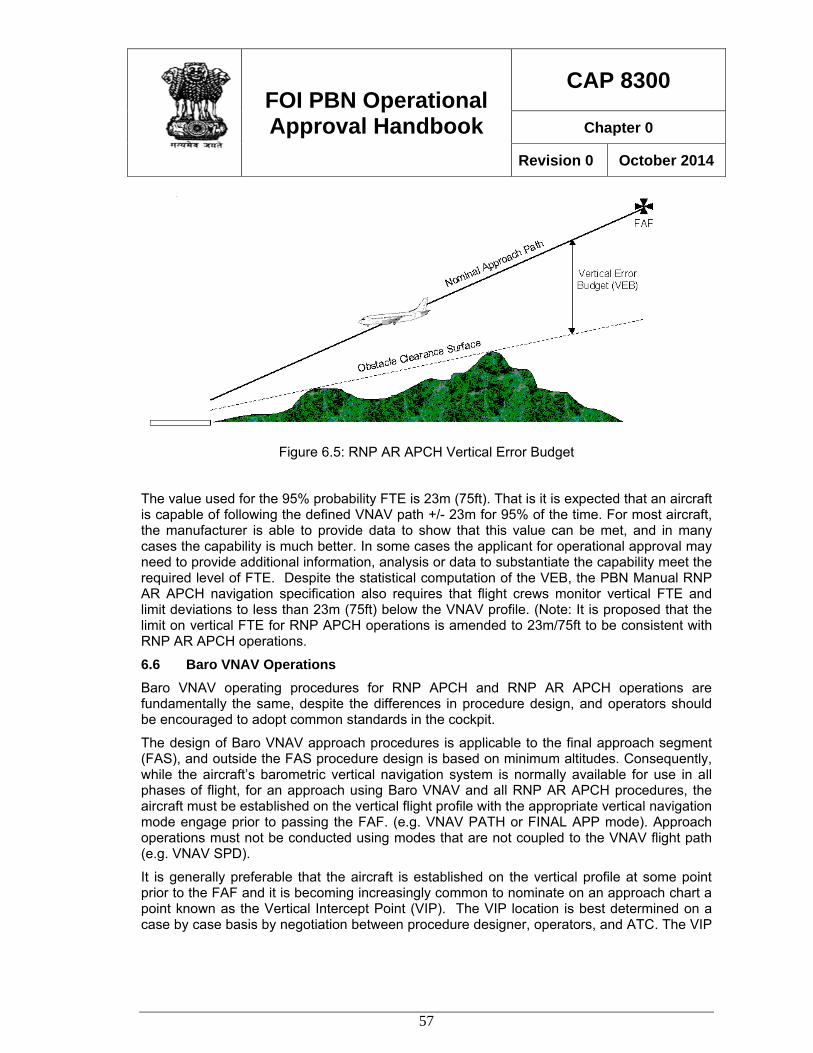
FOI PBN Operational Approval Handbook
CAP 8300
Chapter 0
Revision 0 October 2014
57
Figure 6.5: RNP AR APCH Vertical Error Budget
The value used for the 95% probability FTE is 23m (75ft). That is it is expected that an aircraft is capable of following the defined VNAV path +/- 23m for 95% of the time. For most aircraft, the manufacturer is able to provide data to show that this value can be met, and in many cases the capability is much better. In some cases the applicant for operational approval may need to provide additional information, analysis or data to substantiate the capability meet the required level of FTE. Despite the statistical computation of the VEB, the PBN Manual RNP AR APCH navigation specification also requires that flight crews monitor vertical FTE and limit deviations to less than 23m (75ft) below the VNAV profile. (Note: It is proposed that the limit on vertical FTE for RNP APCH operations is amended to 23m/75ft to be consistent with RNP AR APCH operations.
6.6 Baro VNAV Operations Baro VNAV operating procedures for RNP APCH and RNP AR APCH operations are fundamentally the same, despite the differences in procedure design, and operators should be encouraged to adopt common standards in the cockpit.
The design of Baro VNAV approach procedures is applicable to the final approach segment (FAS), and outside the FAS procedure design is based on minimum altitudes. Consequently, while the aircraft’s barometric vertical navigation system is normally available for use in all phases of flight, for an approach using Baro VNAV and all RNP AR APCH procedures, the aircraft must be established on the vertical flight profile with the appropriate vertical navigation mode engage prior to passing the FAF. (e.g. VNAV PATH or FINAL APP mode). Approach operations must not be conducted using modes that are not coupled to the VNAV flight path (e.g. VNAV SPD).
It is generally preferable that the aircraft is established on the vertical profile at some point prior to the FAF and it is becoming increasingly common to nominate on an approach chart a point known as the Vertical Intercept Point (VIP). The VIP location is best determined on a case by case basis by negotiation between procedure designer, operators, and ATC. The VIP
FOI PBN Operational Approval Handbook
CAP 8300
Chapter 0
Revision 0 October 2014
58
is useful in identifying to ATC the latest point at which the aircraft needs to be established, and this concept is similar to the well established air traffic control practice of establishing an aircraft on an ILS prior to the glide path intercept point. ATC vectoring rules should also require that if an aircraft is taken off track, or is vectored to join the approach inside the IAF, then both lateral and vertical tracking is established at some distance (commonly 2NM) prior to the VIP.
As noted earlier, VNAV operating procedures must ensure that the correct altimeter subscale setting is used.
While barometric VNAV operations provide significant safety benefits over non-precision approaches, mismanagement of the VNAV function can introduce significant risk. During the operational approval process great care and attention should be made to examine the VNAV system management, mode control, annunciation and logic. Crews need to be well trained in recognising situations which can lead to difficulty such as VNAV path capture (from above or below), speed and altitude modification, on approach logic and other characteristics. In some installations, in order to protect the minimum airspeed, mode reversion will cause the aircraft to pitch for airspeed rather than to maintain the flight path and descent below the vertical flight path may not be obvious to the flight crew.
It is recommended that the final approach segment for barometric VNAV approach is flown with autopilot coupled. Consideration should also be given to the manufacturer’s policy and the aircraft functioning at the DA. In some cases lateral and vertical flight guidance remains available and continued auto-flight below the DA is available. This can be of significant advantage, particularly is complex, difficult or limited terrain and runway environments and continued accurate flight path guidance is available below the DA, reducing potential deviations in the visual segment. Other manufacturer’s (and States) adopt different policies and lateral and vertical flight guidance is not available below the DA. The evaluation of crew procedures and training must include an assessment of the effect that the loss of flight guidance has on safe operations, particularly where the approach procedure does not conform to the normal design rules (e.g. offset final approach or non standard approach gradient.)
FOI PBN Operational Approval Handbook
CAP 8300
Chapter 0
Revision 0 October 2014
59
Chapter 7 AIRCRAFT QUALIFICATION 7.1 Eligibility In the process of issuing an operational approval for PBN, it is necessary to establish that the aircraft and its navigation and other systems are suitable for the specific operation. For conventional navigation, rules and processes exist for the design, manufacture, certification and operation of navigation systems in accordance with well established standards and practices. For PBN operations it is less likely, especially given the recent development of the PBN Manual and State regulatory documentation, that an aircraft is approved in the state of manufacture in accordance with the requirements of a particular navigation specification.
Consequently it is often necessary to authorise PBN operations without the benefit of complete airworthiness approval documentation, and this is an important step in the operational approval process. It is important to understand that the lack of specific airworthiness certification does not imply any lack of capability. All operational aircraft will as a matter of course be “airworthy” in the general sense, however the specific airworthiness with regard to a particular PBN operation may not have been completed. In such cases it is necessary to demonstrate that the aircraft is suitably equipped and capable of the PBN operation. The terms “certification” and “approval” should be used appropriately, and care needs to be taken not to confuse the two.
Operational approval needs to consider the capability, functionality, performance and other characteristics of the navigation and other relevant flight systems against the requirements of the particular PBN operation and determine that the operation is sound. In some cases operational mitigations and alternative means of meeting the PBN Manual requirements may need to be examined and approved.
The term eligibility is used to describe the fundamental aircraft capability, however considerable additional evaluation may be needed before an eligible aircraft is determined to be adequate for the issue of an operational approval.
Following the development of the PBN Manual and relevant State regulatory material, a number of manufacturers have or are in the process of obtaining airworthiness approval for PBN operations. In such cases the operational approval process can be greatly simplified. It is expected that in due course manufacturers will pursue PBN Manual compliant airworthiness approvals both for new and previously certified aircraft.
A considerable number of aircraft may never, for engineering, economical or practical reasons, be able to obtain airworthiness approval consistent with all PBN Manual navigation specifications. Despite this, operational approval is frequently able to be achieved, by the implementation of operational limitations, specific operating procedures, data collection, systems evaluation or trialling.
7.2 Aircraft Evaluation The AFM will commonly include a statement of RNAV or RNP capability, which often leads to the assumption that the aircraft is approved for a particular PBN operation. Unfortunately the basis upon which a statement is included in an AFM is often not consistent with the PBN Manual, as many of the terms, requirements, operating practices and other characteristics either differed or did not exist at the time the AFM was issued.
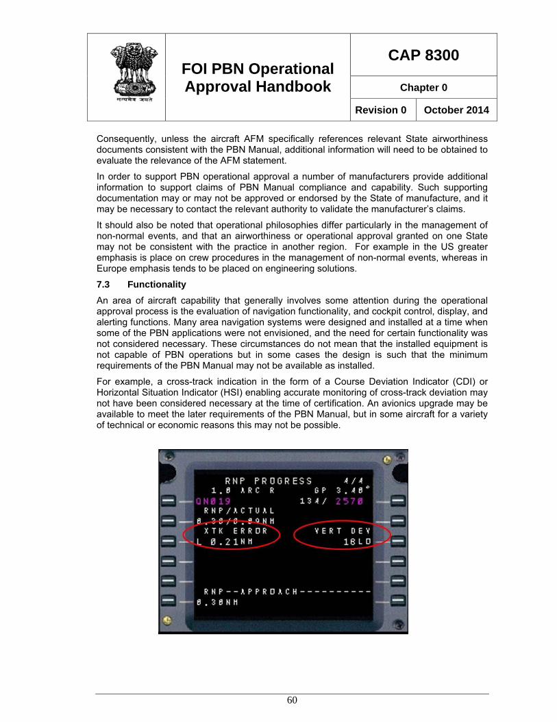
FOI PBN Operational Approval Handbook
CAP 8300
Chapter 0
Revision 0 October 2014
60
Consequently, unless the aircraft AFM specifically references relevant State airworthiness documents consistent with the PBN Manual, additional information will need to be obtained to evaluate the relevance of the AFM statement.
In order to support PBN operational approval a number of manufacturers provide additional information to support claims of PBN Manual compliance and capability. Such supporting documentation may or may not be approved or endorsed by the State of manufacture, and it may be necessary to contact the relevant authority to validate the manufacturer’s claims.
It should also be noted that operational philosophies differ particularly in the management of non-normal events, and that an airworthiness or operational approval granted on one State may not be consistent with the practice in another region. For example in the US greater emphasis is place on crew procedures in the management of non-normal events, whereas in Europe emphasis tends to be placed on engineering solutions.
7.3 Functionality An area of aircraft capability that generally involves some attention during the operational approval process is the evaluation of navigation functionality, and cockpit control, display, and alerting functions. Many area navigation systems were designed and installed at a time when some of the PBN applications were not envisioned, and the need for certain functionality was not considered necessary. These circumstances do not mean that the installed equipment is not capable of PBN operations but in some cases the design is such that the minimum requirements of the PBN Manual may not be available as installed.
For example, a cross-track indication in the form of a Course Deviation Indicator (CDI) or Horizontal Situation Indicator (HSI) enabling accurate monitoring of cross-track deviation may not have been considered necessary at the time of certification. An avionics upgrade may be available to meet the later requirements of the PBN Manual, but in some aircraft for a variety of technical or economic reasons this may not be possible.
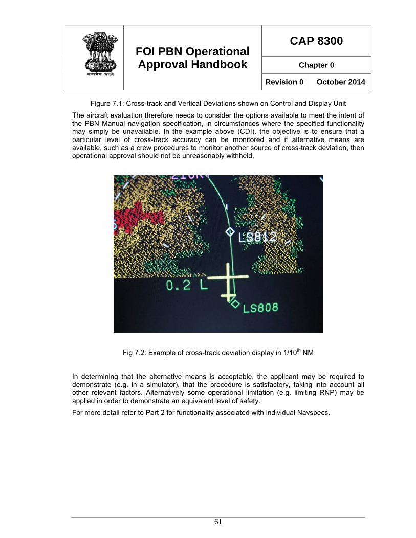
FOI PBN Operational Approval Handbook
CAP 8300
Chapter 0
Revision 0 October 2014
61
Figure 7.1: Cross-track and Vertical Deviations shown on Control and Display Unit
The aircraft evaluation therefore needs to consider the options available to meet the intent of the PBN Manual navigation specification, in circumstances where the specified functionality may simply be unavailable. In the example above (CDI), the objective is to ensure that a particular level of cross-track accuracy can be monitored and if alternative means are available, such as a crew procedures to monitor another source of cross-track deviation, then operational approval should not be unreasonably withheld.
Fig 7.2: Example of cross-track deviation display in 1/10th NM
In determining that the alternative means is acceptable, the applicant may be required to demonstrate (e.g. in a simulator), that the procedure is satisfactory, taking into account all other relevant factors. Alternatively some operational limitation (e.g. limiting RNP) may be applied in order to demonstrate an equivalent level of safety.
For more detail refer to Part 2 for functionality associated with individual Navspecs.
FOI PBN Operational Approval Handbook
CAP 8300
Chapter 0
Revision 0 October 2014
62
Chapter 8 FLIGHT CREW TRAINING 8.1 General The amount and type of training required for flight crews varies significantly depending upon a number of factors including;
• Previous training and experience
• Complexity of operations
• Aircraft equipment
Consequently it is not possible to specify for each of the PBN Manual navigation specifications the particular training that will be required, and some judgement is required in determining the content and structure of flight crew training. The navigation specifications in the PBN Manual cover a wide range of operations, from basic to complex and that training needs to be appropriate to the particular circumstances.
Each navigation specification includes guidance on flight crew training although it should be noted that the training specified for each operation is generally considered independently. It should be recognised that the PBN Manual is a compilation of guidance material, some of which has been in existence in other forms for some number of years, and the training requirements may not be entirely consistent across the range of navigation specifications.
For en-route operations, ground training is commonly sufficient to provide crews with the necessary knowledge. Delivery methods will vary, but classroom training, computer based training or in some cases desk-top simulator training is normally sufficient.
Arrival and departure operations and particularly approach operations normally will also require some flight simulator training, in addition to ground training and briefings.
Consideration should also be placed upon the need for flight crews to demonstrate that competency standards are achieved and the means of documentation of qualification.
8.2 Knowledge requirements For all PBN operations the following areas of knowledge will need to be included, with varying content and complexity depending upon the particular operations.
Area navigation principles. Area navigation is the basis for all PBN operations, and the same general knowledge of is applicable to all navigation specifications. Note that pilots with previous experience may not be familiar with some more advanced features such as Radius to Fix legs (RF) and the application of vertical navigation.
Navigation system principles. Flight crews should have a sound knowledge of the navigation system to be used. The relevance of the navigation system to particular PBN Manual navigation specifications should be clearly established. For example knowledge of inertial navigation and updating is relevant to requirements for some oceanic and remote navigation specifications, as is knowledge of GNSS is necessary for RNP AR APCH operations.
Equipment operation and functionality. Considerable variation exists in the operation of navigation equipment, cockpit controls, displays and functionality. Crews with experience on one type of installation or aircraft may require additional training on another type of
FOI PBN Operational Approval Handbook
CAP 8300
Chapter 0
Revision 0 October 2014
63
equipment. Special attention should be placed on the differences between stand-alone GNSS equipment and Flight Management Systems with GNSS updating.
Flight planning Knowledge of the relevant aspects of each of the navigation specifications that relate to flight planning is required.
Operating procedures. The complexity of operating procedures varies considerably between PBN operations. RNP APCH and RNP AR APCH require a detailed knowledge of standard operating procedures for both normal and non-normal operations.
Monitoring and alerting. Flight crew responsibilities for performance monitoring and alerting provided by the navigation system or other means (crew procedures) must be understood.
Limitations. Operating limitations (e.g. time limits, minimum equipment) vary both between and within the PBN Manual navigation specifications and flight crews need to be able to recognise and plan accordingly.
Contingencies Alternative means of navigation or other contingency procedures must be included.
Air Traffic Control procedures. Flight crews need to be aware of ATC procedures that may be applicable to PBN operations.
8.3 Flight Training requirements Approach and departure operations, and in some cases arrivals require flight training and the demonstration of flight crew competency.
The amount of flight training required varies with the PBN operation, previous flight crew training and experience and other factors. In the course of operational approval all relevant circumstances need to be considered and the training evaluated for completeness and effectiveness. Ongoing and recurrent training should also be considered.
Despite the variation in training requirements, some general guidelines may be helpful in evaluating the extent of training that might be required. Some examples of “average” cases are included below. These examples assume that flight crews have previous relevant experience, and have completed knowledge training curriculum.
En-Route: In general flight training is not required.
Arrival & Departure: As departure and arrival operations require strict adherence to track during periods of higher workload, and are associated with reduced clearance from terrain and increased traffic, crews need to be fully conversant with the operation of the navigation system. Consequently, unless crews have significant appropriate operational experience simulator or flight training must be provided. Particular care should be taken in the evaluation of this type of operation conducted with stand-alone GNSS equipment where functional limitations require crew intervention.
RNP APCH: Training for RNP APCH conducted using stand-alone GNSS equipment, particularly in a single-pilot aircraft normally requires multiple in-flight exercises each with pre-flight and post-flight briefing. Considerable attention needs to be given to programming and management of the navigation system, including in-flight re-programming, holding, multiple approaches, mode selection and recognitions, human factors and the navigation system functionality.
FOI PBN Operational Approval Handbook
CAP 8300
Chapter 0
Revision 0 October 2014
64
Approaches conducted in FMS equipped aircraft, are generally much easier to manage and aircraft are generally fitted with good map displays assisting situational awareness. Normal operations are generally quite simple and competency can be achieved with one or two approaches. Additional training should be provided to achieve familiarity and competency in operations which involve changes to the planned approach, system alerting and missed approach requirement. Attention also needs to be placed on the method of vertical navigation, using standard non-precision approach procedures (LNAV) or barometric VNAV (LNAV/VNAV). As a guide initial training for crews with previous relevant GNSS & RNAV experience typically can achieve competency during one full flight simulator training session with associated pre-flight and post flight briefing.
RNP AR APCH: RNP AR APCH operations are able to deliver improvements in safety and efficiency which are enabled by the Authorisation Required process which ensures that all areas of the operating are carefully examined and appropriate attention placed on all aspects of the operation including training. Accordingly training for RNP AR APCH operations should be thorough and ensure that crews are able to manage operations safely within the additional demands placed on procedure design, aircraft and crew procedures.
As a guide, crews without previous relevant experience (e.g. RNP APCH with Baro VNAV), may require a course of ground training (1 – 2 days) plus simulator flight training (4hrs or more) in order to achieve competency.
Additional information regarding flight crew knowledge and training is included in PART 2.
FOI PBN Operational Approval Handbook
CAP 8300
Chapter 0
Revision 0 October 2014
65
PART 2 PBN OPERATIONAL APPROVALS
Chapter 1 Overview 1.1 General In this Part guidance is provided to assist DGCA inspectors in the evaluation of an application for PBN Operational Approval for each of the PBN Manual Navigation Specifications.
The PBN Manual contains a statement of the operational requirements for each type of operation, and while it is necessary that the Operational Approval evaluation determines that the proposed operation meets the minimum requirements, it is also necessary that an assessment is made of the operator’s capability to meet the operational intent of the particular navigation specification.
It should be noted that each of the PBN Manual navigation specifications has a history of its own and the minimum requirements have originated over differing time frames and in some cases geographical operating requirements. In the development of the PBN manual it has not been possible to correlate all requirements of the individual navigation specifications and some inconsistencies may be noted between specifications.
Operations approval inspectors who have a good understanding of the underlying principles, intent and application appropriate to each of the navigation specifications should be able to manage any such limitation in the PBN Manual without difficulty.
1.2 Responsibility for Operational Approval Evaluation Overall responsibility for the evaluation of an operational approval application will be assigned to a Flight Operations Inspector (FOI), who is (where possible) experienced and trained in PBN operations. The assigned inspector should have access to other specialist expertise where required.
It should be recognised that PBN is an operational concept and the primary task is to determine that the applicant’s operating practices, procedures and training are adequate. Although some evaluation of aircraft eligibility and airworthiness is required during the operational approval process, PBN operational approval is not primarily an airworthiness task.
In some cases, particularly where documentation is available to demonstrate the aircraft eligibility, the FOI may be satisfied that any airworthiness issues are addressed and assistance from airworthiness experts may not be necessary. However in most cases issues of configuration control, ongoing maintenance, minimum equipment lists, training of maintenance personnel etc., should be assessed by qualified airworthiness inspectors in consultation with the FOI.
1.3 Issue of Approval Depending upon the legislative and organisational structure within each State, the method of issue of an operational approval will vary, although in most cases the approval will consist of the issue of an operations specification (OPSPEC) or a letter of approval.
OPSPECs should be annotated as shown in the table below to show the individual PBN operational approvals granted. The remarks as noted should also be included on the OPSEC
FOI PBN Operational Approval Handbook
CAP 8300
Chapter 0
Revision 0 October 2014
66
to assist in identifying existing approvals which are equivalent to PBN navigation specifications. For example, it should be noted (as shown) that an RNAV 5 approval is applicable in B-RNAV airspace. This will assist regulators to recognise and accept OPSECS issued in accordance with PBN navigation specifications and help to avoid misunderstandings as the transition is made to the global adoption of PBN. .
However issued the approval will commonly include conditions, as PBN operations may be conducted using a variety of aircraft, systems and procedures which have yet to be universally standardised.
It is not necessary to issue separate airworthiness and operational approvals for PBN operations. The operational approval is issued on the basis that an assessment is made or the airworthiness aspects of the operation.
1.4 Job Aids Job aids (annexure to CAP 8200) have been developed to assist DGCA inspectors in managing the process of PBN operational approvals. The job aids provide both inspectors and operators with guidance on the documentation required to be included in an operator’s application, and the items that must be assessed by the FOI in order for an operational approval to be issued. The job aids also serve as means of recording the documentation process.
The job aids summarise the key elements to be assessed, and should be used as a guide to the approval process but frequent reference to the ICAO PBN Manual (DOC 9613) and DGCA FOI PBN Operational Approval Handbook will be required to identify detailed requirements for approval.
FOI PBN Operational Approval Handbook
CAP 8300
Chapter 0
Revision 0 October 2014
67
Chapter 2 RNAV 10 2.1 General RNAV 10 operations have been, prior to the development of the PBN concept authorized as RNP 10 operations. An RNAV 10 operational approval does not change any requirement nor does it affect operators that have already obtained an RNP 10 approval.
RNP 10 was developed and implemented at a time when the delineation between RNAV and RNP had not been clearly defined. As the requirements for RNP 10 did not include a requirement for on-board performance monitoring and alerting, it is more correctly described as an RNAV operation and hence the inclusion in the PBN Manual as RNAV 10.
Recognising that airspace, routes, airworthiness and operational approvals have been designated as RNP 10, further declaration of airspace, routes, and aircraft and operator approvals may continue to use the term RNP 10, while the PBN Manual application will be known as RNAV 10.
RNAV 10 is applicable to operations in oceanic and remote areas and does not require any ground-based navigation infrastructure or assessment.
2.2 ATS communications and surveillance The PBN Manual does not address communication or air traffic services (ATS) surveillance requirements that may be specified for operation on a particular route or area. These requirements are specified in other documents, such as the aeronautical information publications (AIP) and ICAO Regional Supplementary Procedures (Doc 7030). An operational approval conducted in accordance with the requirements of the PBN Manual assumes that operators and flight crews take into account all the communication and surveillance requirements related to RNP 10 routes.
2.3 Summary As RNAV 10 is intended for use in oceanic and remote areas the navigation specification is based on the use of Long Range Navigation Systems. A minimum of two LRNs is required for redundancy.
Commonly available LRNs are:
• INS
• IRS
• GNSS
The most common combinations of dual LRNs are:
• Dual INS
• Dual IRS
• Dual GNSS
• GNSS/IRS (IRS updated by GNSS)
Inertial systems (unless updated by GNSS) are subject to a gradual loss of position accuracy with time (drift rate) and therefore are subject to a maximum time limit in order to meet the
FOI PBN Operational Approval Handbook
CAP 8300
Chapter 0
Revision 0 October 2014
68
RNAV 10 accuracy requirement. The basic time limit is 6.2 hrs, but this may be extended by updating or by demonstration of reduced drift rate (<3.7km/2NM per hr.)
GNSS position is continuously updated and not subject to any time limit. However GNSS is subject to some operational limitations that impact on oceanic and remote navigation.
The minimum level of GNSS receiver (TSO C129) is capable of fault detection (FD) but will not provide a navigation solution if a fault is detected. Consequently, no matter how many serviceable satellites are available, the continued availability of GNSS cannot be assured and is therefore this standard of GNSS is unsuitable for oceanic and remote navigation. In order to be approved for oceanic and remote applications a GNSS receiver must be capable of excluding a faulty satellite from the solution (Fault detection and Exclusion/FDE) so that continuity of navigation can be provided. FDE is standard for GNSS receivers based on later TSO C145A/146A standards and is available as an option or modification for TSO C129( ) receivers. Consequently, where a TSO C129 ( ) GNSS is used to satisfy the requirement for one or both of the LRNs it needs to be determined that the receiver is capable of FDE and approved for oceanic/remote operations.
Despite the GNSS receiver capability for FDE, the satellite constellation may not always be adequate to provide sufficient satellite for the redundant navigation solutions to be computed in order to identify and eliminate a faulty satellite from the position solution, and in such situations FDE is not available. In order to limit the exposure to the potential loss of a navigation solution due to unavailability of FDE, a prediction of satellite availability is required, and the maximum period during which FDE is predicted to be unavailable is 34 minutes. This time limit is based on the assumption that should a fault occur during a period when FDE is unavailable, then navigation accuracy is reduced (DR).
For an IRS/GNSS system the same 34 minute time limit is also applied to a loss of FDE.
Due to the time limitations applicable to INS or IRS the operator needs to evaluate the route(s) to be flown to determine that RNAV 10 capability can be satisfied. Accordingly an RNAV 10 operational approval is not universal for aircraft without GNSS and needs to apply to specific routes or be subject to the operator’s procedures for route evaluation.
As inertial position accuracy slowly deteriorates over time since update, for aircraft with INS or IRS only, some attention needs to be placed on radio updating. Aircraft equipped with a Flight Management System normally provide automatic radio updating of inertial position. Automatic updating is normally considered adequate in such circumstances, provided the aircraft is within a reasonable distance of the radio aids at the point at which the last update is expected. If any doubt exists then the operator should be required to provide any an analysis of the accuracy of the update.
Manual updating is less common, and the operational approval needs to be based on a more detailed examination of the circumstances. Guidance is provided in the PBN Manual.
2.4 Operating Procedures The standard operating procedures adopted by operators flying on oceanic and remote routes should normally be generally consistent with RNAV 10 operations, except that some additional provisions may need to be included to specifically address RNAV 10 operations.
FOI PBN Operational Approval Handbook
CAP 8300
Chapter 0
Revision 0 October 2014
69
A review of the operator’s procedure documentation against the requirements of the PBN Manual and the DGCA regulatory requirements should be sufficient to ensure compliance.
The essential elements to be evaluated are that the operator’s procedures ensure that:
• The aircraft is serviceable for RNAV 10 ops
• RNAV 10 capability is indicated on the flight plan
• Route limitations are defined and observed (e.g. time limits)
• En-route loss of capability is identified and reported
• Procedures for alternative navigation are described
GNSS based operations also require the prediction of FDE availability. Most GNSS service prediction programs are based on a prediction at a destination and do not generally provide predictions over a route or large area. However for RNAV 10 operations the probability that the constellation cannot support FDE is remote and this requirement can be met by either a general route analysis or a dispatch prediction of satellite availability. For example a specified minimum satellite constellation may be sufficient to support all RNAV 10 operations with out specific real-time route prediction being required..
2.5 Pilot Knowledge and Training Unless the operator is inexperienced in the use of RNAV, flight crews should possess the necessary skills to conduct RNAV 10 operations with minimal additional training.
Where GNSS is used, flight crews must be familiar with GNSS principles related to en-route navigation.
Where additional training is required, this can normally be achieved by bulletin, computer based training or classroom briefing. Flight training is not normally required.
FOI PBN Operational Approval Handbook
CAP 8300
Chapter 0
Revision 0 October 2014
70
Chapter 3 RNAV 5 3.1 General In the context of the terminology adopted in the PBN Manual, B-RNAV requirements are termed RNAV 5.
B-RNAV approval meets the requirements of RNAV 5 without additional examination.
RNAV 5 is intended for en-route navigation where there is adequate coverage of ground-based radio navigation aids permitting DME/DME or VOR/DME area navigation operations.
Consequently an RNAV 5 route is dependent upon an analysis of the supporting navaid infrastructure. However consideration of navaid coverage it not part of an operational approval as this is the responsibility of the air navigation service provider.
3.2 Summary
• A single RNAV system only is required.
• A navigation database is not required. Manual entry of waypoint data is permitted, but is subject to human error.
• Storage of a minimum of 4 waypoints is required
• Navigation system alerting is not required.
• Navigation displays in the pilot’s forward view must be sufficient to permit track following and manoeuvring.
• The maximum cross-track error deviation permitted is 2.5NM
• An RNAV system failure indication is required.
3.3 INS or IRS An INS or IRS system may be used for RNAV 5. If automatic radio updating is not carried out a time limit of 2 hrs applies from the last on ground position update, unless an extended limit has been justified.
3.4 GNSS GNSS approved in accordance with ETSO C129(A), FAA TSO C129 (A) or later meets the requirements of RNAV 5.
Stand-alone receivers manufactured to ETSO C129 or FAA TSO C129 are also applicable provided they include pseudo-range step detection and health word checking functions.
GNSS based operations require prediction that a service (with integrity) will be available for the route. Most GNSS availability prediction programs are computed for a specific location (normally the destination airport) and are unable to provide predictions over a route or large area. However for RNAV 5 the probability of a loss of GNSS integrity is remote and the prediction requirement can normally be met by determining that sufficient satellites are available to provide adequate continuity of service.
FOI PBN Operational Approval Handbook
CAP 8300
Chapter 0
Revision 0 October 2014
71
3.5 Operating procedures For most operators normal RNAV operating procedures will meet the requirements of RNAV 5.
The essential elements to be evaluated are that the operator’s procedures ensure that:
• The aircraft is serviceable for RNAV 5
• RNAV 5 capability is indicated on the flight plan
• En-route loss of capability is identified and reported
• Procedures for alternative navigation are described
If the navigation system does not use a navigation database manual waypoint entry significantly increases the potential for navigation errors. Operating procedures need to be robust to reduce the incidence of human error, including cross-checking of entry, checking of tracks/distances/bearings against published routes and general situational awareness and checking for reasonableness.
Where navigation data is not extracted from a valid database, operations should be limited to not below the minimum obstacle clearance altitude.
As RNAV 5 operations are typically conducted in areas of adequate navaid coverage, contingency procedures will normally involve reversion to conventional ground-based radio navigation.
3.6 Pilot Knowledge and Training Unless the operator is inexperienced in the use of RNAV, flight crews should possess the necessary skills to conduct RNAV 5 operations with minimal additional training.
Where GNSS is used, flight crews must be familiar with GNSS principles related to en-route navigation.
Where additional training is required, this can normally be achieved by bulletin, computer based training or classroom briefing. Flight training is not normally required.
3.7 Operational Approval The operational approval process for RNAV 5 is generally straightforward, given that most aircraft are equipped with RNAV systems which exceed the minimum requirements for RNAV 5.
In most cases the AFM will document RNAV 5 capability and only occasionally will it be necessary to conduct an evaluation of aircraft capability.
FOI PBN Operational Approval Handbook
CAP 8300
Chapter 0
Revision 0 October 2014
72
Chapter 4 RNAV 1 and 2 4.1 General RNAV 1 and 2 navigation specifications constitute harmonization between European Precision RNAV (P-RNAV) and United States RNAV (US-RNAV) criteria.
The RNAV 1 and RNAV 2 navigation specification applies to:
• all ATS routes, including those established in the en-route domain;
• standard instrument departures and arrivals (SID/STAR); and
• instrument approach procedures up to the final approach fix (FAF)/final approach point (FAP).
As RNAV 1 and 2 operations can be based on DME/DME or DME/DME IRU, the navaid infrastructure must be assessed to ensure adequate DME coverage. This is the responsibility of the ANSP and is not part of the operational approval.
There is no difference in the operational approval for RNAV 1 and RNAV 2, and a single RNAV 1 and 2 approval only is issued. An operator with an RNAV 1 and 2 approval is qualified to operate on both RNAV 1 and RNAV 2 routes. RNAV 2 routes may be promulgated in cases where the navaid infrastructure is unable to meet the accuracy requirements for RNAV 1.
4.2 Operational Approval For operators holding either a P-RNAV approval or a US-RNAV approval or both the operational approval is relatively simple and minimal regulatory effort is required.
However, as there are some small differences between the existing European and US specifications, migration to RNAV 1 and 2 approval is not automatic unless the operator holds both US and European approvals.
Operators holding both P-RNAV and US-RNAV approvals qualify for an ICAO RNAV 1 and 2 operational approval without further examination.
For operators holding only a P-RNAV approval, or a US-RNAV approval, it is necessary to ensure that any additional requirements for RNAV 1 and 2 are met. The PBN Manual provides tables identifying these additional requirements. (Part B, Chapter 3 para 3.3.2.7)
Operators not holding a B-RNAV or US-RNAV approval need to be evaluated to determine that they meet the requirements for RNAV 1and 2.
It should be noted that there is no obligation on an operator to obtain an RNAV 1 and 2 approval or to migrate an exiting approval to ICAO RNAV 1 and 2 if their existing approval is applicable to the area of operation. Operators that operate only in P-RNAV airspace or only in US-RNAV airspace can continue to do so in accordance with a P-RNAV or US-RNAV approval respectively.
4.3 Summary For RNAV 1 and 2 operational approval:
• A single RNAV system only is required.
FOI PBN Operational Approval Handbook
CAP 8300
Chapter 0
Revision 0 October 2014
73
• The RNAV system may be based on:
• DME/DME
• DME/DME/IRU
• GNSS (including GNSS/IRU)
• A navigation database is required.
• Navigation displays in the pilot’s forward view must be sufficient to permit track following and manoeuvring.
• The maximum cross-track error deviation permitted is ½ navigation accuracy
• 0.5NM for RNAV 1
• 1.0 NM for RNAV 2
• An RNAV system failure indication is required.
4.4 GNSS GNSS approved in accordance with ETSO C129(A), FAA TSO C129 (A) or later meets the requirements of RNAV 1 and 2.
Stand-alone receivers manufactured to ETSO C129 or FAA TSO C129 are also applicable provided they include pseudo-range step detection and health word checking functions.
GNSS based operations require prediction that a service (with integrity) will be available for the route. Most GNSS availability prediction programs are computed for a specific location (normally the destination airport) and are unable to provide predictions over a route or large area. However for RNAV 1 and 2 the probability of a loss of GNSS integrity is remote and the prediction requirement can normally be met by determining that sufficient satellites are available to provide adequate continuity of service.
The PBN Manual makes reference to the possibility of position errors cased by the integration of GNSS data and other positioning data and the potential need for deselection of other navigation sensors. This method of updating is commonly associated with IRS/GNSS systems and the weighting given to radio updating is such that it is unlikely that any potential reduction in positioning accuracy will be significant in proportion to RNAV 1 and 2 navigation accuracy.
4.5 Functionality The PBN Manual lists the functional requirements for RNAV 1 and 2.
For the majority of air transport aircraft equipped with FMS, the required functionalities, with the exception of the provision of a non-numeric lateral deviation display are normally available. For this category of aircraft lateral deviation is displayed on a map display, usually with a numeric indication of cross-track error in 1/10th NM. In some cases a numeric indication of cross-track error may be provided outside the primary field of view (e.g. CDU). Acceptable lateral tracking accuracy for both RNAV 1 and RNAV 2 routes is adequate provided the autopilot is engaged or flight director is used.
FOI PBN Operational Approval Handbook
CAP 8300
Chapter 0
Revision 0 October 2014
74
Aircraft equipped with stand-alone GNSS navigation systems, should be installed to provide track guidance via a CDI or HSI. A lateral deviation display is often incorporated in the unit, but is commonly not of sufficient size nor suitable position to allow either pilot to manoeuvre and adequately monitor cross-track deviation.
Caution should be exercised in regard to the limitations of stand-alone GNSS systems with respect to ARINC 424 path terminators. Path terminators involving an altitude termination are not normally supported due to a lack of integration of the lateral navigation system and the altimetry system. For example, a departure procedure commonly specifies a course after takeoff until reaching an specified altitude (CA path terminator). Using a basic GNSS navigation system it is necessary for the flight crew to manually terminate the leg on reaching the specified altitude and then navigate to the next waypoint, ensuring that the flight path is consistent wit the departure procedure. This type of limitation does not preclude operational approval (as stated in the PBN Manual functional requirements) provided the operator’s procedures and crew training are adequate to ensure that the intended flight path and other requirements can be met for all SIDs and STAR procedures.
4.6 Operating procedures Operators with en-route RNAV experience will generally meet the basic requirements of RNAV 1 and 2 and the operational approval should focus on procedures associated with SIDs and STARs.
Particular attention should be placed on selection of the correct procedure from the database, review of the procedures, connection with the en-route phase of flight and the management of discontinuities. Similarly an evaluation should be made of procedures manage selection of a new procedures, including change of runway, and any crew amendments such as insertion or deletion of waypoints.
As RNAV 1 and 2 operations are typically conducted in areas of adequate navaid coverage, contingency procedures will normally involve reversion to conventional ground-based radio navigation.
4.7 Pilot Knowledge and Training During the operational approval, particular attention should be placed on the application of the pilot knowledge and training to the conduct of RNAV 1 and 2 SIDs and STARs. Most crews will already have some experience RNAV operations, and many of the knowledge and training items will have previously been covered in past training.
Execution of SIDs and STARs, connection with the enroute structure and transition to approach procedures require a thorough understanding of the airborne equipment, and its functionality and management.
Particular attention should be placed on:
• The ability of the airborne equipment to fly the designed flight path. This may involve pilot intervention where the equipment functionality is limited
• Management of changes (procedure, runway, track)
• Turn management (turn indications, airspeed & bank angle, lack of guidance in turns)
• Route modification (insertion/deletion of waypoints, direct to waypoint)
FOI PBN Operational Approval Handbook
CAP 8300
Chapter 0
Revision 0 October 2014
75
• Intercepting route, radar vectors
Where GNSS is used, flight crews must be trained in GNSS principles related to en-route navigation.
Flight training for RNAV 1 and 2 is not normally required, and the required level of competence can normally be achieved by classroom briefing, computer based training , desktop simular training, or a combination of these methods. Computer based simulator programs are available from a number of GPS manufacturers which provide a convenient method for familiarity with programming and operation of stand-alone GNSS systems.
Although not specifically mentioned in the PBN Manual RNAV 1 and 2 navigation specification, where VNAV is used for SIDs and STARs attention should be given to the management of VNAV and specifically the potential for altitude constraints to be compromised in cases where the lateral flight path is changed or intercepted.
FOI PBN Operational Approval Handbook
CAP 8300
Chapter 0
Revision 0 October 2014
76
Chapter 5 RNP 4 5.1 General RNP 4 is a navigation specification applicable to oceanic and remote airspace, and supports 30NM lateral and 30NM longitudinal separation.
5.2 Operational Approval Operators holding an existing RNP 4 operational approval do not need to be re-examined as the PBN Manual requirements are essentially unchanged.
5.3 ATS communications and surveillance The PBN Manual does not address communication or air traffic services (ATS) surveillance requirements that may be specified for operation on a particular route or area. These requirements are specified in other documents, such as the aeronautical information publications (AIP) and ICAO Regional Supplementary Procedures (Doc 7030). An operational approval conducted in accordance with the requirements of the PBN Manual assumes that operators and flight crews take into account all the communication and surveillance requirements related to RNP 4 routes.
5.4 Summary For RNP 4 operational approval:
• Two long range navigation systems are required
• At least one GNSS receiver is required
• A navigation database is required.
• Navigation displays in the pilot’s forward view must be sufficient to permit track following and manoeuvring
• The maximum cross-track error deviation permitted is 2NM
5.5 GNSS GNSS is fundamental to the RNP 4 navigation specification, and carriage avoids any need to impose a time limit on operations. The consequences of a loss of GNSS navigation need to be considered and there are a number of requirements in the navigation specification to address this situation.
Irrespective of the number of GNSS receivers carried, as there is a remote probability that a fault may be detected en-route, a fault detection and exclusion (FDE) function needs be installed. This function is not standard on TSO C129a receivers and for oceanic operations a modification is required.
With FDE fitted, integrity monitoring is available provided there are sufficient satellites of a suitable configuration in view. Some reduction in availability of a positioning service with integrity results, as additional satellites are required, although for RNP 4 as the alerting requirements are large, it is highly improbable that service will not be available.
The RNP 4 navigation specification does not require a dispatch prediction of the availability of integrity monitoring (with FDE) in the case of a multi-sensor system. In this context a system
FOI PBN Operational Approval Handbook
CAP 8300
Chapter 0
Revision 0 October 2014
77
integrating GNSS and IRS is a suitable multi-sensor system. A prediction of GNSS availability is therefore not considered necessary the multi-sensor system will revert to IRS in the remote possibility that GNSS is unavailable.
Other methods of integrity monitoring, discussed under the heading Aircraft Autonomous Integrity Monitoring (AAIM) in Part 1, utilise hybrid GNSS/IRS monitoring systems which provide increased availability sufficient to not require a dispatch prediction to be conducted. Examples of these systems are Honeywell HIGH and Litton AIME.
A difficulty is that most availability programs are based on a specific location (normally the destination airport) and are unable to provide predictions over a route or large area. For RNP 4, as the alerting limits are large, provided a minimum number of satellites are available, availability can be assured without the need to carry out a prediction for each flight.
5.6 Functionality For the majority of air transport aircraft equipped with FMS, the required functionalities, with the exception of the provision of a non-numeric lateral deviation display are normally available. For this category lateral deviation is not normally displayed on a CDI or HSI, but is commonly available on a map display, usually with a numeric indication of cross-track error in 1/10th NM. In some cases a numeric indication of cross-track error may be provided outside the primary field of view (e.g. CDU).
Aircraft equipped with stand-alone GNSS navigation systems, should be installed to provide track guidance via a CDI or HSI. The CDI/HSI must be coupled to the RNAV route providing a direct indication of lateral position reference the flight planned track. This type of unit in en-route mode (normal outside 30NM from departure and destination airports) defaults to a CDI/HSI full-scale display of 5NM, which is adequate for RNP 4. A lateral deviation display is often incorporated in the unit, and may be suitable if of sufficient size and position to allow either pilot to manoeuvre and monitor cross-track deviation.
The navigation specification includes some requirements for fly-by transition criteria. The default method for RNAV systems to manage turns at the intersection of “straight” route segments (TF/TF), is to compute, based on groundspeed and assumed angle of bank, a position at which the turn should commence so that the resulting radius will turn inside the angle created by the two consecutive segments and “fly-by” the intermediate waypoint. For aircraft fitted with a stand-alone GNSS system or an FMS fly-by transitions are a standard function and should not require specific evaluation. However a stand-alone GNSS receiver may require a pilot action to initiate the turn. All turns are limited by the physical capability of the aircraft execute a turn of suitable radius. In normal cases where the angle between track is small there is seldom a problem, but operators need to be aware that large angle turns, particularly at high altitude where TAS is high and bank angle is commonly limited can be outside the aircraft capability. While this condition is rare, flight crews need to be aware of the aircraft and avionics limitations.
5.7 Operating Procedures The standard operating procedures adopted by operators flying on oceanic and remote routes should normally be generally consistent with RNP 4 operations, except that some additional provisions may need to be included to specifically address NP 4 operations.
FOI PBN Operational Approval Handbook
CAP 8300
Chapter 0
Revision 0 October 2014
78
A review of the operator’s procedure documentation against the requirements of the PBN Manual and the DGCA regulatory requirements should be sufficient to ensure compliance.
The essential elements to be evaluated are that the operator’s procedures ensure that:
• The aircraft is serviceable for RNP 4 ops
• RNP 4 capability is indicated on the flight plan
• En-route loss of capability is identified and reported
• Procedures for alternative navigation are described
GNSS based operations also require the prediction of FDE availability. Most GNSS service prediction programs are based on a prediction at a destination and do not generally provide predictions over a route or large area. However for RNP 4 operations the probability that the constellation cannot support FDE is remote and this requirement can be met by either a general route analysis or a dispatch prediction of satellite availability. For example a specified minimum satellite constellation may be sufficient to support all RNP 4 operations without specific real-time route prediction being required.
5.8 Pilot Knowledge and Training Unless the operator is inexperienced in the use of RNAV, flight crews should possess the necessary skills to conduct RNAV 4 operations with minimal additional training.
Where GNSS is used, flight crews must be familiar with GNSS principles related to en-route navigation.
Where additional training is required, this can normally be achieved by bulletin, computer based training or classroom briefing. Flight training is not normally required.

FOI PBN Operational Approval Handbook
CAP 8300
Chapter 0
Revision 0 October 2014
79
Chapter 6 RNP 2 Reserved
FOI PBN Operational Approval Handbook
CAP 8300
Chapter 0
Revision 0 October 2014
80
Chapter 7 Basic RNP 1 7.1 General Basic RNP 1 is based on GNSS positioning. The navigation specification is intended to support arrival and departure procedures without the dependence on a DME/DME infrastructure.
Other than the requirement for GNSS there is no significant difference between the RNAV 1 and 2 navigation specification and basic RNP 1.
7.2 Operational Approval Operators of GNSS equipped aircraft holding an RNAV 1 and 2 operational approvals qualify for Basic RNP 1 subject to the following conditions:
• Manual entry of SID/STAR waypoints is not permitted
• Pilots of aircraft with RNP input selection capability (typically equipped FMS aircraft) should select RNP 1 or lower for Basic RNP 1 SIDs and STARs
• If a Basic RNP 1 SID or STAR extends beyond 30NM from the ARP in some cases the CDI scale may need to be set manually to maintain FTE within limits (see below)
• If a MAP display is used, scaling must be suitable for Basic RNP 1 and a FD or AP used.
Operators of GNSS equipped aircraft holding both P-RNAV and US RNAV approvals also meet the requirements for RNAV 1 and 2 and therefore also qualify for Basic RNP 1 subject to the additional conditions listed in the previous paragraph.
Applicants without previous relevant approvals will need to be assessed against the requirements of the Basic RNP 1 navigation specification.
7.3 Summary
• A single RNAV system only is required.
• GNSS is required
• A navigation database is required.
• Navigation displays in the pilot’s forward view must be sufficient to permit track following and manoeuvring
• MAP display (without CDI) is acceptable provided FD or AP is used
• The maximum cross-track error deviation permitted is 0.5NM
7.4 Stand-alone GNSS systems The most basic qualifying system is a stand-alone GNSS receiver (TSO C129(a)) which should coupled to a CDI or HSI display providing course guidance and cross-track deviation indications. This type of system may also be integrated with a map display, however primary guidance is provided by the CDI/HSI. The receiver normally incorporates a self-contained control and display unit but the interface may also be provided by a separate CDU.
FOI PBN Operational Approval Handbook
CAP 8300
Chapter 0
Revision 0 October 2014
81
In this arrangement Basic RNP 1 capability is provided when in terminal mode. In terminal mode:
CDI scaling is automatically set at +/- 1NM full scale deflection
HAL is automatically set to 1 NM (RAIM alert limit)
In the default mode (en-route) CDI scaling increases to +/- 5NM and HAL increases to 2NM. Terminal mode cannot be manually selected but will be system selected provided certain conditions exist.
For departure, provided the current flight plan includes the departure airport (usually the ARP) terminal mode will be active and annunciated. (An annunciator panel should be installed in accordance with the manufacturer’s recommendations and DGCA airworthiness regulations). In the general case terminal mode will automatically switch to en-route mode at 30NM from the departure ARP. If the Basic RNP 1 SID extends past 30NM, the CDI scaling will no longer be adequate to support the required FTE limit (+/- 0.5NM), and flight crew action is necessary to manually select +/-1NM CDI scaling.
On arrival, provided the current flight plan route includes the destination airport (ARP) the receiver will automatically switch from en-route to terminal mode at 30NM from the ARP. If the STAR commences at a distance greater than 30NM radius from the destination, then en-route CDI scaling of +/-5NM is inadequate for Basic RNP 1 and must be manually selected to +/-1NM. Note: Manual selection of +/- 1NM CDI scale (terminal scaling) does not change the mode, and en-route RAIM alert limits apply.
7.5 RNP Systems Aircraft equipped with a flight management system, normally integrate positioning from a number of sources (radio navaids, GNSS) often using a multi-mode receiver (MMR) with IRS.
In such systems the navigation capability, alerting and other functions are based upon an RNP capability, and the RNP for a particular operation may be a default value, a pilot selected value or a value extracted from the navigation database.
There is normally no automatic mode switching (as in the case of a stand-alone receiver), although the default RNP may vary with the phase of flight.
For this type of operation it is necessary for the flight crew to select either RNP 1 or accept a lesser default value before commencement of a Basic RNP 1 SID or STAR.
7.6 Integrity availability GNSS based operations require prediction that a service (with integrity) will be available for the route. Most GNSS availability prediction programs are computed for a specific location (normally the destination airport) and are unable to provide predictions over a route or large area. However for Basic RNP 1 the probability of a loss of GNSS integrity is remote and the prediction requirement can normally be met by determining that sufficient satellites are available to provide adequate continuity of service.
FOI PBN Operational Approval Handbook
CAP 8300
Chapter 0
Revision 0 October 2014
82
7.7 Deselection of radio updating The PBN Manual makes reference to the possibility of position errors cased by the integration of GNSS data and other positioning data and the potential need for deselection of other navigation sensors. This method of updating is commonly associated with IRS/GNSS systems and the weighting given to radio updating is such that it is unlikely that any potential reduction in positioning accuracy will be significant in proportion to Basic RNP 1 navigation accuracy.
7.8 Functionality The PBN MANUAL lists the functional requirements for Basic RNP 1 which are identical to RNAV 1 and 2.
For the majority of air transport aircraft equipped with FMS, the required functionalities, with the exception of the provision of a non-numeric lateral deviation display are normally available. For this category of aircraft lateral deviation is displayed on a map display, usually with a numeric indication of cross-track error in 1/10th NM. In some cases a numeric indication of cross-track error may be provided outside the primary field of view (e.g. CDU). Acceptable lateral tracking accuracy for Basic RNP 1 routes is adequate provided the autopilot is engaged or flight director is used.
Aircraft equipped with stand-alone GNSS navigation systems, should be installed to provide track guidance via a CDI or HSI. An lateral deviation display is often incorporated in the unit, and may be suitable if of sufficient size and position to allow either pilot to manoeuvre and monitor cross-track deviation.
Caution should be exercised in regard to the limitations of stand-alone GNSS systems with respect to ARINC 424 path terminators. Path terminators involving an altitude termination are not normally supported due to a lack of integration of the lateral navigation system and the altimetry system. For example, a departure procedure commonly specifies a course after takeoff until reaching an specified altitude (CA path terminator). Using a basic GNSS navigation system it is necessary for the flight crew to manually terminate the leg on reaching the specified altitude and then navigate to the next waypoint, ensuring that the flight path is consistent wit the departure procedure. This type of limitation does not preclude operational approval (as stated in the PBN MANUAL functional requirements) provided the operator’s procedures and crew training are adequate to ensure that the intended flight path and other requirements can be met for all SID and STAR procedures.
7.9 Operating procedures Operators with en-route RNAV experience will generally meet the basic requirements of Basic RNP 1 and the operational approval should focus on procedures associated with SIDs and STARs.
Particular attention should be placed on selection of the correct procedure from the database, review of the procedures, connection with the en-route phase of flight and the management of discontinuities. Similarly an evaluation should be made of procedures manage selection of a new procedures, including change of runway, and any crew amendments such as insertion or deletion of waypoints.
FOI PBN Operational Approval Handbook
CAP 8300
Chapter 0
Revision 0 October 2014
83
7.10 Pilot Knowledge and Training During the operational approval, particular attention should be placed on the application of the pilot knowledge and training to the conduct of Basic RNP 1 SIDs and STARs. Most crews will already have some experience RNAV operations, and many of the knowledge and training items will have previously been covered in past training.
Execution of SIDs and STARs, connection with the enroute structure and transition to approach procedures require a thorough understanding of the airborne equipment, and its functionality and management.
Particular attention should be placed on:
• The ability of the airborne equipment to fly the designed flight path. This may involve pilot intervention where the equipment functionality is limited
• Management of changes (procedure, runway, track)
• Turn management (turn indications, airspeed & bank angle, lack of guidance in turns)
• Route modification (insertion/deletion of waypoints, direct to waypoint)
• Intercepting route, radar vectors
Where GNSS is used, flight crews must be trained in GNSS principles related to en-route navigation.
Flight training for Basic RNP 1 is not normally required, and the required level of competence can normally be achieved by classroom briefing, computer based training, desktop simular training, or a combination of these methods. Computer based simulator programs are available from a number of GPS manufacturers which provide a convenient method for familiarity with programming and operation of stand-alone systems.
Although not specifically mentioned in the PBN MANUAL Basic RNP 1 navigation specification, where VNAV is used for SIDs and STARs attention should be given to the management of VNAV and specifically the potential for altitude constraints to be compromised in cases where the lateral flight path is changed or intercepted.

FOI PBN Operational Approval Handbook
CAP 8300
Chapter 0
Revision 0 October 2014
84
Chapter 8 Advanced RNP Reserved
FOI PBN Operational Approval Handbook
CAP 8300
Chapter 0
Revision 0 October 2014
85
Chapter 9 RNP APCH 9.1 General RNP APCH is the general ICAO designator for PBN approach procedures that are not Authorization Required operations.
As GNSS fulfils the basic requirement of RNP for on-board performance and monitoring, both RNAV (GNSS) and SBAS LPV procedures are types of RNP APCH operations.
RNP APCH procedures will be identified as:
• RNP APCH – LNAV
• RNP APCH – LNAV/VNAV (where a vertical guidance system is used)
• RNP APCH – LPV (Localiser Performance with Vertical Guidance)
• RNP APCH – LP (SBAS approach where vertical guidance is not available)
As the PBN Manual has yet to be amended to include navigation specification for LPV approaches this Chapter currently only deals with RNP APCH – LNAV procedures.
9.2 Characteristics The main characteristics of RNP APCH LNAV operations are:
• IAL chart tiled RNAV (GNSS)
• Approach path constructed as series of straight segments
• Descent to an MDA which is published as an LNAV minima
• Can be flown using basic GNSS (TSOC129a) equipment or RNP 0.3 capable aircraft
• Obstacle clearance lateral tolerances not based on RNP value
• Vertical flight guidance (e.g. Baro-VNAV) may be added
9.3 Flight procedure design Although RNAV (GNSS) approach procedures are designated in the PBN concept as RNP APCH – LNAV procedures there has been no change to the method of procedure design which is in accordance with PANS-OPS RNAV (GNSS) design criteria.
Instrument approach charts continue to include RNAV (GNSS) in the title, and descent is made to a minimum descent altitude which is shown as an LNAV minimum, or LNAV/VNAV where vertical guidance is available.
RNAV (GNSS) procedure design criteria is not currently based on an RNP requirement but on the performance capability of a basic TSO C129a GPS receiver. However it is considered that an aircraft with RNP 0.3 capability has at least equivalent performance and a number of States have authorised RNAV (GNSS) operations based on RNP 0.3 capability.
The RNAV (GNSS) Approach plate shown in Fig 9.4 is an example of a an RNP APCH LNAV/VNAV procedure. Although there is no specific notation, this type of approach can be
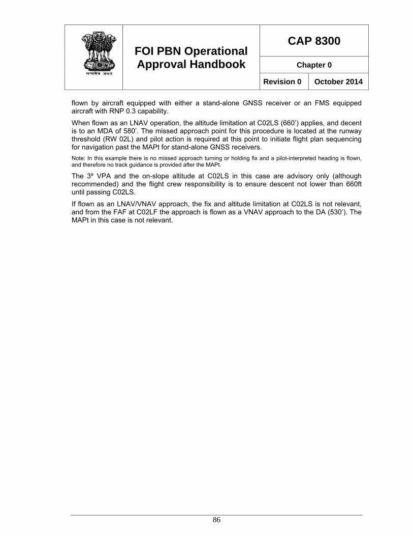
FOI PBN Operational Approval Handbook
CAP 8300
Chapter 0
Revision 0 October 2014
86
flown by aircraft equipped with either a stand-alone GNSS receiver or an FMS equipped aircraft with RNP 0.3 capability.
When flown as an LNAV operation, the altitude limitation at C02LS (660’) applies, and decent is to an MDA of 580’. The missed approach point for this procedure is located at the runway threshold (RW 02L) and pilot action is required at this point to initiate flight plan sequencing for navigation past the MAPt for stand-alone GNSS receivers. Note: In this example there is no missed approach turning or holding fix and a pilot-interpreted heading is flown, and therefore no track guidance is provided after the MAPt.
The 3º VPA and the on-slope altitude at C02LS in this case are advisory only (although recommended) and the flight crew responsibility is to ensure descent not lower than 660ft until passing C02LS.
If flown as an LNAV/VNAV approach, the fix and altitude limitation at C02LS is not relevant, and from the FAF at C02LF the approach is flown as a VNAV approach to the DA (530’). The MAPt in this case is not relevant.
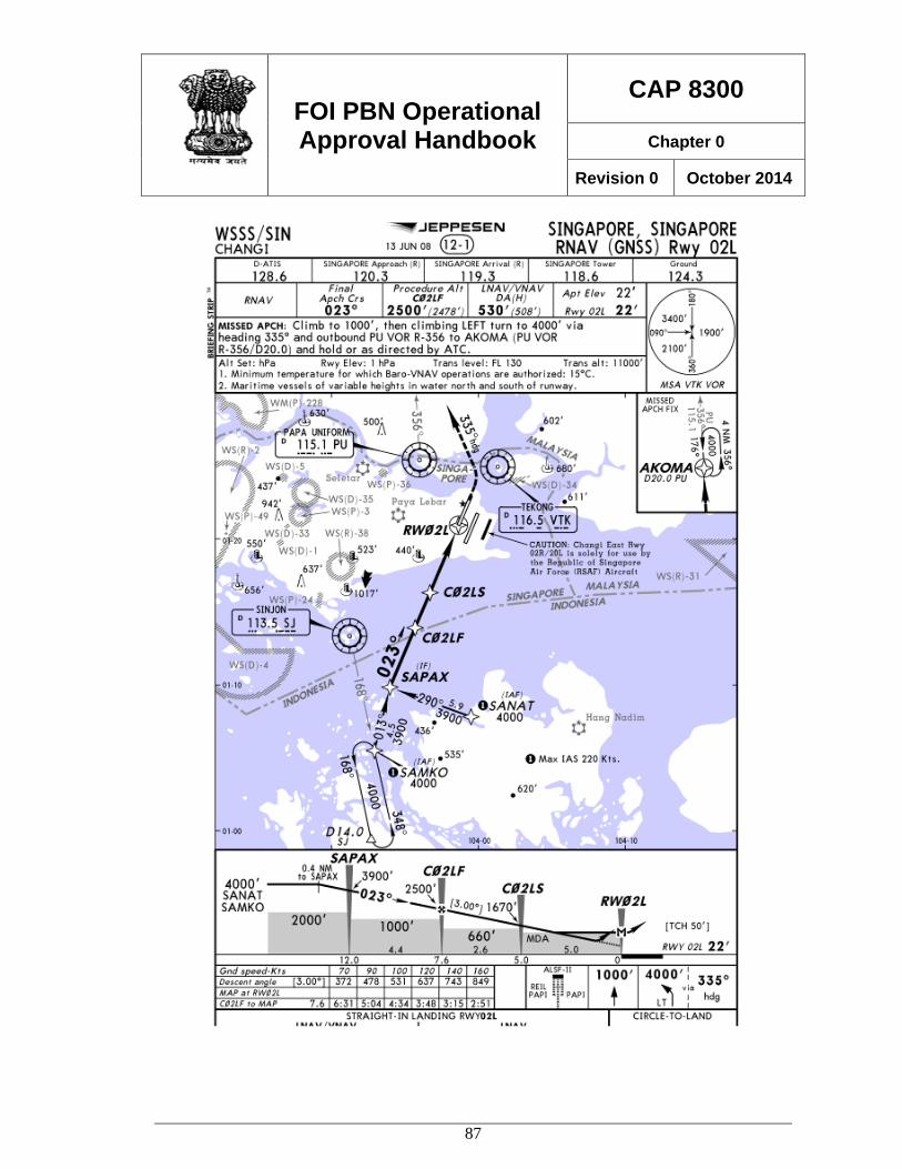
FOI PBN Operational Approval Handbook
CAP 8300
Chapter 0
Revision 0 October 2014
87
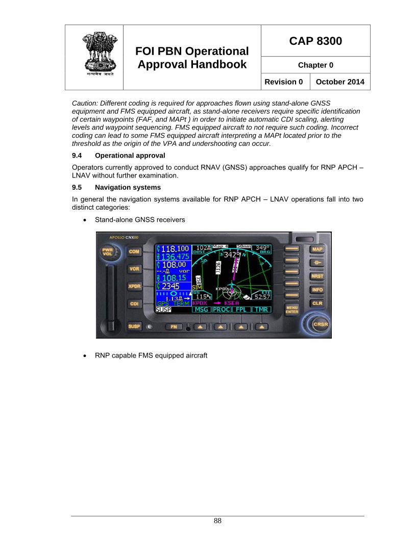
FOI PBN Operational Approval Handbook
CAP 8300
Chapter 0
Revision 0 October 2014
88
Caution: Different coding is required for approaches flown using stand-alone GNSS equipment and FMS equipped aircraft, as stand-alone receivers require specific identification of certain waypoints (FAF, and MAPt ) in order to initiate automatic CDI scaling, alerting levels and waypoint sequencing. FMS equipped aircraft to not require such coding. Incorrect coding can lead to some FMS equipped aircraft interpreting a MAPt located prior to the threshold as the origin of the VPA and undershooting can occur.
9.4 Operational approval Operators currently approved to conduct RNAV (GNSS) approaches qualify for RNP APCH – LNAV without further examination.
9.5 Navigation systems In general the navigation systems available for RNP APCH – LNAV operations fall into two distinct categories:
• Stand-alone GNSS receivers
• RNP capable FMS equipped aircraft
FOI PBN Operational Approval Handbook
CAP 8300
Chapter 0
Revision 0 October 2014
89
Although both types of navigation systems have similar capability there are significant differences in functionality, cockpit displays, and flight crew procedures.
9.6 Stand-alone systems This type of system is commonly represented by a panel-mounted self-contained unit comprising a GNSS receiver incorporating a control unit, a lateral deviation indicator, and an annunciator panel. In some cases the unit may also include a map display. Units may also be installed with a separate CDU, or a separate map display.
Commonly installed in general aviation aircraft, this type of system is also frequently installed in commuter airline aircraft and occasionally in older jet air transport category aircraft.
For IFR approach operations, the installation must provide a lateral deviation displayed on a CDI or HSI in the pilot’s primary field of view. This is normally done by connecting the GNSS receiver output to a dedicated CDI or by enabling the selection of the navigation source to the primary HSI/CDI to be selected. (The in-built CDI provided on most stand-alone GNSS receivers is generally not considered adequate, even if the unit is installed in the pilot’s primary field of view.)
An annunciator panel is standard equipment for approach operations and must be located in a suitable position on the instrument panel. Navigation mode annunciation of terminal mode, approach armed, and approach active is required.
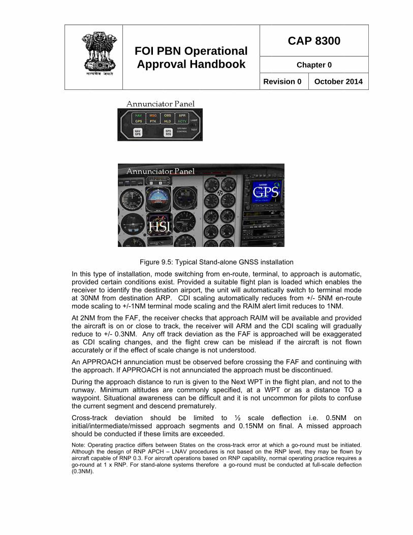
In thisprovidreceivat 30Nmode
At 2NMthe airreduceas CDaccura
An APthe ap
Duringrunwawaypothe cu
Cross-initial/ishouldNote: OAlthougaircraft go-roun(0.3NM
s type of insted certain cer to identify
NM from descaling to +
M from the Frcraft is on e to +/- 0.3NDI scaling cately or if the
PPROACH approach. If A
g the approaay. Minimumoint. Situatiorrent segme
-track deviintermediated be conductOperating practgh the design ocapable of RN
nd at 1 x RNP).
FOI PAppr
Figure 9
tallation, moconditions exy the destinstination AR/-1NM termi
FAF, the recor close to
NM. Any offchanges, ane effect of sc
annunciationAPPROACH
ach distancem altitudes onal awareneent and desc
iation shoue/missed apted if these tice differs betof RNP APCH
NP 0.3. For airc. For stand-alo
PBN Oproval Ha
9.5: Typical
ode switchinxist. Provideation airport
RP. CDI scnal mode sc
ceiver checktrack, the re
ff track deviand the flightcale change
must be obis not annun
e to run is givare commoess can be dcend premat
uld be limpproach seglimits are extween States o
H – LNAV proccraft operationsone systems th
perationandboo
Stand-alone
g from en-roed a suitablet, the unit wcaling automcaling and th
ks that approeceiver will ation as the t crew can is not under
bserved befonciated the a
ven to the Nonly specifiedifficult and turely.
mited to ½gments and xceeded. on the cross-trcedures is nots based on RNherefore a go-
nal ok
Re
e GNSS insta
oute, termine flight plan
will automaticmatically redhe RAIM ale
oach RAIM wARM and thFAF is appbe mislead
rstood.
ore crossing approach mu
ext WPT in ed, at a WP
it is not unc
½ scale d0.15NM on
rack error at wbased on the
NP capability, n-round must be
CAP
Cha
evision 0
allation
al, to approis loaded w
cally switch uces from +rt limit reduc
will be availahe CDI scal
proached wild if the airc
the FAF anust be disco
the flight plaPT or as acommon for
deflection n final. A m
which a go-rouRNP level, th
normal operatine conducted a
P 8300
apter 0
October
ach is automwhich enableto terminal m+/- 5NM en-ces to 1NM.
able and proing will gradl be exagge
craft is not
nd continuingntinued.
an, and not ta distance T
pilots to co
i.e. 0.5NMmissed appr
nd must be inhey may be flong practice requat full-scale def
2014
matic, es the mode -route
ovided dually erated flown
g with
to the TO a nfuse
M on roach
itiated. own by uires a flection
FOI PBN Operational Approval Handbook
CAP 8300
Chapter 0
Revision 0 October 2014
91
At the MAPt, which is commonly located at the runway threshold waypoint sequencing is inhibited, on the assumption that the aircraft is landing. If a missed approach is conducted pilot action is normally required to sequence to the missed approach. Depending on the procedure design (coding) defined track guidance in the missed approach may not be provided, and crews need to understand the navigation indications that are provided and the appropriate technique for managing the missed approach.
On sequencing to the missed approach the receiver automatically reverts to terminal mode.
Close attention needs to be placed on the human factors associated with approaches flown using this type of equipment.
9.7 Flight Management Systems RNP APCH – LNAV operations conducted in aircraft equipped with an FMS and GNSS are managed very differently to stand-alone systems.
As discussed above, RNP APCH procedures are designed using RNAV (GNSS) criteria which were not developed on the basis of GNSS performance rather than an RNP requirement. However it can be shown that an aircraft capable of RNP 0.3 approach operations meets or exceeds the navigation tolerance requirements for RNAV (GNSS) approach procedure design. FMS equipped aircraft therefore are able to fly RNP APCH –LNAV procedures provided RNP 1.0 is selected for the initial, intermediate and missed approach segments, and RNP 0.3 for the final approach segment.
Positioning data, including GNSS, is commonly combined with IRS and radio position to compute an FMS position. The GNSS receiver, which may be separate or part of a multi-mode receiver, provides position data input but does not drive automatic mode switching or CDI scaling. Navigation system integrity may be based on RAIM, but more commonly is provided by a hybrid IRS/GNSS system, which can provide significantly improved integrity protection and availability.
Most FMS aircraft are not equipped with a CDI type non-numerical lateral deviation indicator, although some manufacturers offer a lateral deviation indicator as an option. Where a lateral deviation indicator is provided, the scaling is determined by the manufacturer and may be either a fixed scale or a non-scaled system. Lateral deviation scales may only be available (either automatic or selectable) for certain phases of flight. Automatic scaling similar to stand-alone systems is not provided.
Lateral deviation in this type of system is commonly displayed as a digital cross-track deviation on a map display. Digital cross-track deviation is normally displayed in 1/10th NM, although 1/100th is often available as an option. Digital cross-track deviation may also be subject to rounding. For example where the display threshold is set at 0.15NM on a display capable of only 1 decimal place, the first digital indication of cross-track deviation is displayed as 0.2NM. In the same example, as cross-track deviation is reduced, the lowest value displayed is 0.1NM rounded down when the actual deviation reaches 0.15NM.
Monitoring of deviations within the limits of the navigation specification (0.15NM on final approach) using digital cross-track indications alone can be difficult in some cases. In the example in the previous paragraph the first digital indication of cross-track error is displayed at 0.2NM (although this indication is initiated at 0.15). However, a relative or graphical indication of cross-track error can be derived from the relative position of the aircraft symbol
FOI PBN Operational Approval Handbook
CAP 8300
Chapter 0
Revision 0 October 2014
92
to the flight plan track on the navigation display. For this method to be satisfactory, the size and resolution of the map display needs to be sufficient, and a suitable map scale must be selected.
A go-round should be conducted if the cross-track error reaches 1 x RNP (0.3NM).
Modern large screen (10inch) multi-function displays at 10NM range are generally satisfactory and small deviations can be estimated sufficiently accurately to provide good initial indication of track divergence. Older and smaller displays, including LCD type displays can be less effective and subject to variation (jumping) in displayed position.
Additional cross-track deviation information may also be available on the CDU/MCDU which although outside the normal field of view can be monitored by the PNF/PM. In such cases the evaluation of cockpit displays must also take into consideration the crew operation procedures, callouts etc.
As turns for RNP APCH LNAV approaches are TF/TF transitions and initiation is based turn anticipation logic, track guidance during turns is not provided, and cross-track deviation indications are not provided with respect to a defined turning path. The lack of a defined path is accommodated in the design of the approach procedure, however, it is necessary for the turn to be initiated and correctly executed so that there is no significant under- or over- shooting of the subsequent leg.
In the evaluation cross-track deviation monitoring, it needs to be recognised that track adherence using autopilot or flight director for normal operations is generally very good and little of no cross-track deviation is observed. The evaluation should therefore concentrate on determining that in the unlikely event of a deviation that the crew has sufficient indications to detect and manage any deviation. Deviations can also occur due to delayed or incorrect NAV selection, delay in autopilot connection, autopilot inadvertent disconnection, turbulence, excessive adverse wind, OEI operations and other rare normal or no-normal events.
Navigation system alerting varies between aircraft systems, and unlike stand-alone systems is determined by logic determined by the OEM. Although the operational approval will not normally need to consider the methodology used, the basics of the alerting system must be understood and the approval needs to determine that the operator’s flight crew procedures and training is consistent with the particular aircraft system.
The appropriate RNP for the initial and intermediate segment is RNP 1.0, in the FAS RNP 0.3NM, and RNP 1 for the missed approach. The most common method used to manage RNP is to select RNP 0.3 prior to the IAF, and retain that selection throughout the approach and missed approach. In some cases a default RNP for approaches may apply, and it is sufficient that the crew confirms the correct RNP is available. In other cases crew selection of RNP 0.3 prior to commencement of the approach is necessary. Changing the RNP after passing the IAF is not recommended as it increases crew workload, introduces the opportunity for error (forgetting to change the RNP), and provides little or no operational advantage. For RNP 0.3 operations availability is normally close to 100% and although RNP 0.3 may not be required for the majority of the approach (initial/intermediate segments) the probability of an alert due to the selection of a lower than necessary RNP is extremely low, especially as prediction for RNP 0.3 availability is required to conduct an approach.
FOI PBN Operational Approval Handbook
CAP 8300
Chapter 0
Revision 0 October 2014
93
Less commonly some systems allow the RNP to be automatically extracted from the navigation database.
9.8 Using VNAV advisory information Barometric VNAV is commonly available on modern jet air transport category aircraft equipped with FMS. Other VNAV systems are also available (e.g. SBAS) although few aircraft in this category are fitted.
Aircraft in the general aviation, commuter and light airline categories are generally not equipped with an integrated lateral and vertical navigation system, (typically stand-alone GNSS systems) although increasingly business jets are fitted with capable VNAV systems.
RNP APCH LNAV approach procedures are not dependent upon VNAV and normal non-precision approach principles apply in which obstacle clearance is dependent upon minimum altitudes.
However most RNP APCH LNAV approach procedures are published to indicate an optimum approach gradient (normally 3°) above all minimum obstacle clearance altitudes. Despite there being no change to the underlying non-precision approach obstacle clearance requirements it is recommended that VNAV is used where available to manage the approach and assist in flying a stabilised constant angle flight path. Navigation database coding normally supports a flight path angle where identified on the instrument approach chart.
While the use of VNAV for this purpose is recommended, the operational approval needs to carefully examine the aircraft capability, VNAV functionality, mode selection and annunciation, mode reversion, operating procedures and crew knowledge and training.
It must be clearly understood that VNAV used in this way does not resolve the crew from the responsibility to ensure obstacle clearance is maintained by strict adherence to minimum attitudes by use of the pressure altimeter. Descent is made to the LNAV minima which is an MDA. An acceptable alternative method is to add a margin the LNAV minimum altitude (typically 50-100ft) and to treat the higher MDA as a DA, on the basis that any height loss during the go-round will result in descent not lower than the published MDA. In some States operational approval under certain circumstances may be available to consider the published MDA as a DA.
During the operational approval due attention should be placed to vertical navigation at all stages of the approach. Although an approach angle is normally only published for the FAS extension of the coded angle to the IF should be considered in order to provide additional protection and avoid potential problems with intercepting the vertical path. Operators will normally need to make a special request to the navigation database supplier for the extension of the vertical path angle coding.
Normally an approach will be designed so that the vertical path clears all minimum altitudes in the final approach segment by a convenient margin (50-100ft). This allows for some tolerance in the VNAV system and avoids any tendency to level off in order to observe any hard altitude limitations. Where a suitable tolerance is not provided consideration should be given to revising the design of the procedure to be more VNAV friendly.
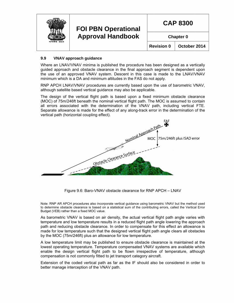
9.9 Whereguidedthe usminim
RNP Aalthou
The d(MOCall errSeparvertica
Note: Rto deterBudget
As batempepath amade by the
A low lowestenablecompe
Extensbetter
VNAV appe an LNAV/Vd approach se of an apum which is
APCH LNAVgh satellite b
design of th) of 75m/246rors associarate allowancal path (horiz
Figu
RNP AR APCHrmine obstacle(VEB) rather t
rometric VNerature and land reducingfor low temp
e MOC (75m
temperaturet operating te the desigensation is n
sion of the cmanage inte
FOI PAppr
proach guidVNAV minimand obstac
pproved VNA a DA and m
V/VNAV procbased vertic
e vertical fl6ft beneath ated with thce is made fzontal coupl
ure 9.6: Baro
procedures ale clearance is han a fixed MO
NAV is basedow tempera
g obstacle cperature suc/246ft) plus
e limit may temperaturegn vertical fnot common
coded verticerception of
PBN Oproval Ha
dance ma is publishle clearanceAV system. minimum altit
cedures arecal guidance
ight path isthe nominalhe determinfor the effecing effect).
o-VNAV obst
lso incorporatebased on a sta
OC value.
d on air denature results learance. Inch that the dan allowanc
be publishe. Temperatuflight path tly fitted to je
cal path as the VNAV p
perationandboo
hed the proce in the fina
Descent intudes in the
e currently b may also be
s based upol vertical flighnation of thct of any alo
tacle clearan
e vertical guidaatistical sum o
nsity, the acin a reduced
n order to codesigned verce for low tem
d to ensure ure compensto be flown
et transport c
far as the IFpath.
nal ok
Re
cedure has bal approach this case iFAS do not
ased upon te applicable
on a fixed mht path. The
he VNAV png-track erro
nce for RNP
nce using baroof the contribut
ctual verticald flight path
ompensate fortical flight pamperature.
obstacle clesated VNAV n irrespectivcategory airc
F should als
CAP
Cha
evision 0
been designsegment is is made to t apply.
the use of be.
minimum obe MOC is assath, includior in the det
APCH – LN
ometric VNAV ting errors, call
flight path angle loweror this effecath angle cle
earance is msystems are
ve of tempecraft.
so be consid
P 8300
apter 0
October
ed as a vertdependent the LNAV/V
barometric V
bstacle clearsumed to cong vertical termination o
NAV
but the methodled the Vertica
angle variesring the apprct an allowanears all obst
maintained ae available werature, alth
dered in ord
2014
tically upon
VNAV
VNAV,
rance ontain
FTE. of the
d used al Error
s with roach nce is tacles
at the which hough
der to
FOI PBN Operational Approval Handbook
CAP 8300
Chapter 0
Revision 0 October 2014
95
When conducting an LNAV/VNAV approach, the primary means of obstacle clearance is provided by the VNAV system rather than the altimeter, and adherence to the vertical flight path within reasonable tolerance is required.
ICAO Doc 8168 PANS-OPS Volume 1 provides operational guidance on the conduct of approach with barometric VNAV guidance. Vertical deviations from the defined path should be limited to +100/-50ft. Note: To retain consistency with RNP AR APCH is expected that the PBN Manual will amend the vertical FTE limit to 75ft.
The operational approval needs to carefully examine the aircraft capability, VNAV functionality, mode selection and annunciation, mode reversion, operating procedures and crew knowledge and training.
9.10 Altimeter setting procedures As the flight path guidance provided by a barometric VNAV system is directly affected by the barometric pressure subscale setting, particular attention needs to be placed to pressure setting procedures and associated aircraft systems.
9.11 Vertical Navigation Systems Most commercial jet transport aircraft are equipped with a baro VNAV system that is compliant with FAA AC 20-129 which has been in existence for many years.
It can be difficult to reconcile the specified minimum barometric VNAV system performance requirements in the Attachment to the PBN Manual (which are derived from FAA AC 20-129) with actual VNAV operating practice. However the actual performance of installed VNAV systems has been demonstrated to provide accurate vertical guidance which meets the standard necessary for RNP APCH.
AC 20-129 makes the assumption that altimetry system error (ASE) will be compensated and consequently no allowance is made for altimetry errors in the estimation of vertical TSE. In practice a residual error does exist in most aircraft and manufacturers are generally able to provide data. As a guide, ASE is typically less than 60ft.
The FTE standard in the PBN Manual (and AC 20-129) is larger than is normally observed during approach operations. For example, the FTE requirement applicable to most approach operations is 200ft, compared to observed values which are commonly less than 60ft (3 σ).
Potential errors associated with waypoint resolution, vertical path angle definition, and ATIS errors are not included.
Although a statistical analysis of VNAV component errors is not required for basic Baro-VNAV operations, it may be helpful to asses the typical VNAV errors, in a similar manner to that applied to Baro-VNAV for RNP AR APCH operations.
A root sum square calculation using typical PBN Manual VNAV equipment and FTE values, plus an allowance for other errors, provides the following result at a 5NM FAF.
RSS TSE = ( ) ( ) ( ) ( ) ( ) ( )222222 ATISVPAWPRASEFTEVNAV +++++
= 234ft
FOI PBN Operational Approval Handbook
CAP 8300
Chapter 0
Revision 0 October 2014
96
Assuming: VNAV equipment error (99.7%) 100ft
FTE (99.7%) 200ft
ASE (Assumed max 99.7% error) 60ft
WPR 3ft
VPA based on 1° resolution/0.5° error 26ft
ATIS (assumed 99.7%) 20ft Note: Horizontal coupling error or ANPE is considered separately in PANS-OPS and does not need to be included.
This value is slightly higher than the figure given in the PBN Manual RSS value (224ft) but less than the 246ft MOC used in design.
Given that the commonly observed VNAV errors, including FTE (with autopilot) are significantly less than the values used in this example, the performance of a VNAV system compliant with FAA AC 20-129 can be expected to be consistent with the assumption of a 246ft fixed MOC.
Additional mitigation is also provided by the operational requirement to monitor the vertical FTE and conduct a go-round if the deviation below the vertical path exceeds 50ft (or 75ft if amended.)
For aircraft approved for RVSM operations the ASE and VNAV errors can be expected to be small. If any doubt exists as to the suitability of a particular VNAV system, additional data on actual in-service performance should be sought.
9.12 GNSS Availability Prediction. As the current GPS constellation is unable to provide 100% availability at all levels of service, there a periods, depending upon a number of factors, when an RNP approach cannot be conducted. Consequently a prediction of availability is conducted to enable the flight crew and dispatchers (where applicable) to take into consideration the availability of GNSS capability to be expected at any particular location.
Availability of RNP APCH operations is normally limited by the approach HPL which is set to 0.3NM by default for stand-alone GNSS receivers. At this level of service, the periods when an RNP service is unavailable are short, and a delay in departure or en-route, is often sufficient to schedule an arrival when the service is predicted to be available.
An operation is not available, or should be discontinued when an alert is displayed to the flight crew. Consequently availability is determined by the means used to generate an alert, which as discussed previously, varies between aircraft. In order to be most accurate and effective a prediction of availability needs to be based on the same parameters that are used in the particular aircraft systems, rather than a general prediction of a parameter such as HPL.
The operator needs to make arrangements for prediction service to be available that replicates the monitoring system on the aircraft. Prediction services are readily available from a number of commercial sources. The prediction should be based on the latest satellite health data, which is readily available, and take into account other factors such as high terrain. On board prediction programs are generally unsatisfactory in that they are unable to take account of satellite NOTAMS and terrain masking.
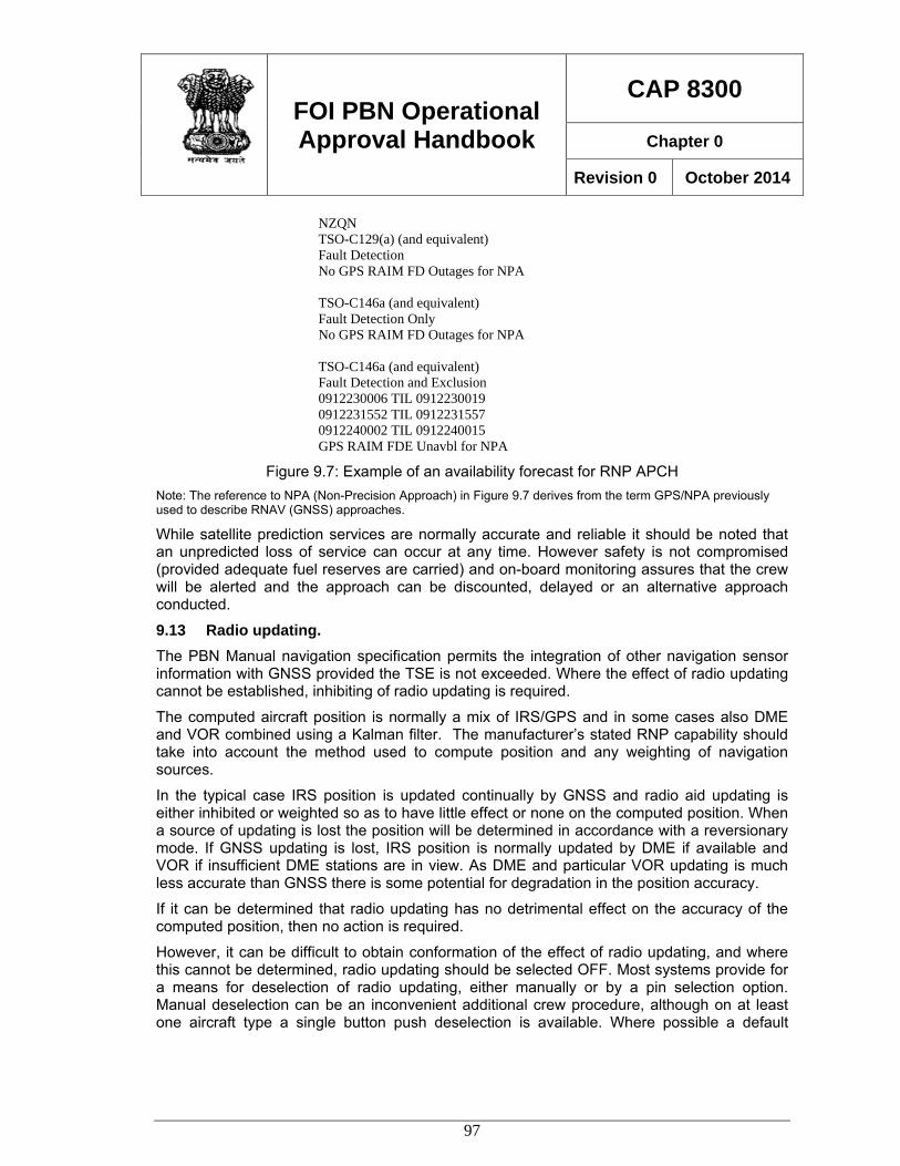
FOI PBN Operational Approval Handbook
CAP 8300
Chapter 0
Revision 0 October 2014
97
NZQN TSO-C129(a) (and equivalent) Fault Detection No GPS RAIM FD Outages for NPA TSO-C146a (and equivalent) Fault Detection Only No GPS RAIM FD Outages for NPA TSO-C146a (and equivalent) Fault Detection and Exclusion 0912230006 TIL 0912230019 0912231552 TIL 0912231557 0912240002 TIL 0912240015 GPS RAIM FDE Unavbl for NPA
Figure 9.7: Example of an availability forecast for RNP APCH Note: The reference to NPA (Non-Precision Approach) in Figure 9.7 derives from the term GPS/NPA previously used to describe RNAV (GNSS) approaches.
While satellite prediction services are normally accurate and reliable it should be noted that an unpredicted loss of service can occur at any time. However safety is not compromised (provided adequate fuel reserves are carried) and on-board monitoring assures that the crew will be alerted and the approach can be discounted, delayed or an alternative approach conducted.
9.13 Radio updating. The PBN Manual navigation specification permits the integration of other navigation sensor information with GNSS provided the TSE is not exceeded. Where the effect of radio updating cannot be established, inhibiting of radio updating is required.
The computed aircraft position is normally a mix of IRS/GPS and in some cases also DME and VOR combined using a Kalman filter. The manufacturer’s stated RNP capability should take into account the method used to compute position and any weighting of navigation sources.
In the typical case IRS position is updated continually by GNSS and radio aid updating is either inhibited or weighted so as to have little effect or none on the computed position. When a source of updating is lost the position will be determined in accordance with a reversionary mode. If GNSS updating is lost, IRS position is normally updated by DME if available and VOR if insufficient DME stations are in view. As DME and particular VOR updating is much less accurate than GNSS there is some potential for degradation in the position accuracy.
If it can be determined that radio updating has no detrimental effect on the accuracy of the computed position, then no action is required.
However, it can be difficult to obtain conformation of the effect of radio updating, and where this cannot be determined, radio updating should be selected OFF. Most systems provide for a means for deselection of radio updating, either manually or by a pin selection option. Manual deselection can be an inconvenient additional crew procedure, although on at least one aircraft type a single button push deselection is available. Where possible a default
FOI PBN Operational Approval Handbook
CAP 8300
Chapter 0
Revision 0 October 2014
98
option where radio updating is normally OFF is preferred, with the option of crew selection to ON in the unlikely event of a loss of GNSS updating.
9.14 Operating Procedures In recent years most manufacturers have developed recommendations for RNAV (GPS)/RNAV (GNSS) procedures. Although the manufacturer recommendations should be followed, the operational approval should include an independent evaluation of the operators’ proposed procedures. RNP APCH operating procedures should be consistent with the operator’s normal procedures where possible in order to minimise any human factors elements associated with the introduction RNP operations.
9.15 Procedure selection and review Operating procedures need to address the selection of the approach from the navigation database and the verification and review of the displayed data. Commonly some changes to an operator’s normal practice will be involved, and the evaluation will need to recognise that new techniques may be appropriate to RNP approach operations.
In most cases the instrument approach chart will contain RNAV (GNSS) in the title and the clearance issued will refer to RNAV, the runway, and usually a suffix letter e.g. RNAV (GNSS) RWY 20 X. Due to avionics limitations the available approaches may be displayed in an abbreviated format e.g. RNVX. In some cases the suffix letters (X, Y, and Z) may not be supported. Care needs to be taken that flight crew procedures take into account these limitations and that the correct procedure is selected and then checked.
It should be recognised that the approach chart assumes less importance for an RNP APCH procedure once the procedure is loaded in the FMS and checked. During the approach only limited reference to the approach chart is normally required.
9.16 Use of autopilot and flight director The manufacturer’s guidance will normally provide recommendations on the use of auto-pilot and/or flight director. In general, RNP APCH procedures should be flown with autopilot coupled if the aircraft is equipped, enabling the crew to place greater attention to monitoring the approach and taking advantage of the reduced FTE normally available. This policy should not preclude the use of flight director (consistent with manufacturer procedures) when autopilot is not available or in other circumstances (e.g. OEI operations). Note: The FTE used by the aircraft manufacturer to demonstrate RNP capability may be dependent upon the use of a coupled auto-pilot or flight director. A lesser RNP capability may be applicable to procedures flown manually using a map display.
9.17 GNSS updating RNP APCH procedures are dependent on GNSS positioning, and the availability of GNSS, (as well as the available level of RNP) should be checked prior to commencement of an approach.
The failure of a GNSS receiver (i.e. an equipment failure) is commonly annunciated, but in the normal case where duplicated GNSS receivers are installed, the approach can continue normally using the serviceable receiver.
FOI PBN Operational Approval Handbook
CAP 8300
Chapter 0
Revision 0 October 2014
99
A loss of GNSS updating due to a loss of signal may occur at any time, but an alert will not normally be generated immediately. Where position integrity can be maintained following the loss of GNSS a valid position continues to be displayed.
When the required performance cannot be sustained an alert will be generated, and the normal procedure is to conduct a go-round, unless the approach can be conducted visually.
Inspectors should be familiar with the alerting system applicable to the specific aircraft under consideration to ensure that operating procedures and crew knowledge and training is consistent with the system functionality.
9.18 Flight crew knowledge and training Successful RNP APCH LNAV and LNAV/VNAV approach operations depend heavily on sound flight crew knowledge and training.
The type of navigation system has a significant effect on the conduct of this type of procedure and flight training must take this factor into account.
Crews operating aircraft equipped with basic stand-alone systems typically require significantly more flight training than crews operating FMS equipped aircraft. The amount of training will vary depending on the flight crew’s previous RNAV experience, however the following is provide as a guide.
Ground training. Ground training including computer-based training and classroom briefings, will normally require a minimum of one day.
Simulator training. For FMS systems operated by crews with experience in the use of the FMS for the conduct of conventional approach procedures, a pre-flight briefing session and one 2 to 4 hours simulator session per crew is commonly sufficient.
For operators of stand-alone systems, simulator or flight training may require 2 or more training sessions. Proficiency may be achieved in normal uncomplicated operations in a short period of time however additional flight time needs to be scheduled to ensure competency in the management of approach changes, go-round, holding and other functions, including due consideration of human factors. Where necessary initial training should be supplemented by operational experience in VMC or under supervision.
9.19 Navigation Database RNP APCH operations are critically dependent on valid data. The PBN Manual includes the basic requirements associated with the use and management of navigation databases.
Although the navigation database should be obtained from a qualified source, operators must also have in place sound procedures for the management of data. Experienced RNAV operators who understand the importance of reliable data will normally have such procedures established, however less experienced operators may not fully understand the need for comprehensive management procedures and may need to develop or improve existing procedures.
It should be noted that despite the requirement for the database supplier to comply with RTCA DO200A/EUROCAE document ED 76 that data errors may still occur and dependence on quality management alone is not sufficient.
FOI PBN Operational Approval Handbook
CAP 8300
Chapter 0
Revision 0 October 2014
100
Cyclic Data Updates: There is no specific requirement in the PBN Manual navigation specification to implement checks of RNP APCH approach data at each update. Despite this operators should be encouraged to implement an electronic means of ensuring that the data loaded onto the aircraft remains valid. Although the operating tolerances for RNP APCH provide a level of conservatism, and GNSS driven approach procedures are inherently extremely accurate, electronic data errors are not in any way related to these factors and gross errors can occur just as easily as minor ones.
A cyclic comparison of new versus old data must be designed to identify changes that have not been ordered prior to the effective date for each database cycle. Action can then be taken to rectify the problem before the effective date, or issue corrective action such as notices to flight crew, withdrawal of procedures etc.,
In cases where an effective electronic cyclic data validation process is not available, it may be necessary to conduct re-validation of procedures at each cycle. This is a time-consuming and complex procedure which should be avoided wherever possible.
FOI PBN Operational Approval Handbook
CAP 8300
Chapter 0
Revision 0 October 2014
101
Chapter 10 RNP AR APCH 10.1 General RNP AR APCH operations permit additional safety and efficiency to be achieved by the capability of advanced navigation equipment, aircraft systems and procedures design.
A large number of RNP AR approach and departure procedures have been developed by the industry, commonly sponsored by airlines and designed using commercially developed design criteria. These operations have been approved in a number of States following evaluation on a case-by-case basis, normally for a specific aircraft type and individual operator.
The RNP AR APCH navigation specification has been developed to provide ICAO guidance for similar RNP approach procedures that can be applied generally and to a range of qualified aircraft types.
Procedure design criteria have now been published in ICAO Doc 9905 RNP AR Procedure Design Manual.
10.2 Authorisation Required All operations involve some form of authorisation, either specific or implied, and consequently questions are often raised with regard to the use of the term authorisation required in the context of RNP AR APCH operations.
Early development work on RNP approach procedures was carried out in the United States. Under the US Federal Aviation Regulations, all instrument approach procedures that are in the public domain are developed under FAR Part 97. Where approach procedures (for whatever reason) do not comply with FAR Part 97, the FAA can approve an operation (for a specific operator) as a Special Airworthiness and Aircrew Authorisation Required (SAAAR) procedure.
Accordingly as at the time (1995) the initial work on RNP approach development was undertaken there was no provision in FAR Part 97 for this type of operation, the FAA approved RNP approach operations as procedures with SAAAR.
Subsequently the FAA developed procedure design rules (FAA Order 8260.52) and airworthiness and operational rules (FAA AC90-101A) to support FAA Part 97 RNP SAAAR operations, referred to Public RNP SAAAR. In 2005, when the then Obstacle Clearance Panel (now Instrument Flight Procedures Panel) in ICAO decided to harmonise ICAO procedure design rules with FAA Order 8260.52, it was recognised that there was no equivalent process in ICAO which related to non-conforming or Special procedures. Consequently it was decided to abbreviate the term to Authorisation Required or AR for ICAO application. FAA AC90-101A has now been published in February 2011 and these operations are referred to as RNP AR APCH harmonizing PBN terminology.
The implication (whether SAAAR or AR) is that improvements in operational safety and efficiency gained by the utilisation of the capability of advanced navigation capability are matched by an appropriate level of detailed evaluation of aircraft, operations and procedure design.
AR thbeforeoperat
10.3 The athe ca
It shouonly othan 0which
10.4 RNP ANAVIGDESIG
It is aprocedcapab The dexperispecif
erefore reque issuing antions which a
Characterre a numbe
apability of th
• sup
• obs
• fina
• rad
uld be notedone characte0.3. An RNPalso uses R
ProcedureAR APCH pGATION PEGN MANUAL
advisable thdure design
bility, operatin
design criterence in a nic aircraft ty
FOI PAppr
uires the St approval aare identified
ristics er of characthis type of op
pport for RN
stacle cleara
al approach
dius to fix (R
d that while eristic and t
P 0.3 RNP ARNP 0.3 capa
e Design procedures ERFORMANL.
Figure
hat inspecto as AR openg procedur
ria for RNPumber of Stpes, and ind
PBN Oproval Ha
ate to condand that onlyd as Authori
teristics of Rperation, inc
P less than
ance lateral t
vertical obst
F) legs enab
RNP AR APhat many R
AR APCH opability.
are designeNCE AUTHO
10.1: RNP A
ors are famerations areres and proc
P AR APCHtates which dustry devel
perationandboo
uct a full evy qualified oisation Requ
RNP AR APcluding;
0.3 (RNP 0.
tolerance 2 x
tacle clearan
bling circular
PCH procedRNP AR APCperation sho
ed in accordORIZATION
AR APCH O
miliar with the dependentcedure desig
H procedurehave generaloped design
nal ok
Re
valuation of operators aruired.
PCH operatio
1 is the lowe
x RNP
nce provided
r flight paths
dures supporCH operatiould not be c
dance with IREQUIRED
Obstacle Prot
he basic prt upon the
gn.
es has beeally been apn criteria. Th
CAP
Cha
evision 0
all aspects re permitted
ons that com
est currently
d by a vertic
s to be flown
rt low RNP tons do not rconfused wit
CAO Doc 9D (RNP AR
tection
rinciples of proper integ
en derived pplied to indhe ICAO RN
P 8300
apter 0
October
of the operto conduct
mbine to imp
y available)
al error budg
types, that trequire RNPth an RNP A
9905 REQUR) PROCED
RNP AR Agration of ai
from operaividual opera
NP AR Proce
2014
ration RNP
prove
get
this is P less APCH
UIRED DURE
APCH ircraft
ational ators, edure
FOI PBN Operational Approval Handbook
CAP 8300
Chapter 0
Revision 0 October 2014
103
Design Manual provides guidance to States on the early implementation of generic RNP AR approach procedures that can be applied to any appropriately capable aircraft and qualified operating crew. The applicability of the design criteria to a broad range of capable aircraft does result in some operational limitations, particularly in areas of difficult terrain. In order to achieve a satisfactory operational outcome it may be necessary in such cases to approve variations to the design based on specific operational mitigations. The RNP AR Procedure Design Manual makes reference to such circumstances as follows:
1.1.2.5 The design criteria in this manual are applicable to a range of aircraft types and cannot therefore, take into account the full capability of some aircraft types. Consequently procedures designed in accordance with this manual will provide an acceptable operational solution in many but not all circumstances. Where an operationally acceptable solution is not available through the application of the criteria in this manual, development of detailed procedures may be needed to satisfy local conditions. Alternative design solutions may be derived which specify aircraft type or specific performance parameters, special operating conditions or limitations, crew training, operational evaluation or other requirements that can be demonstrated to provide an equivalent level of safety. Such solutions are not the subject of this manual and will require case-by-case flight operational safety assessments and operational approval.
10.5 Operational Approval RNP AR APCH procedures depend upon the integration of aircraft, operations and procedure design to deliver a safe and efficient outcome. Conventional navigation systems which have been in common usage for many years depend on aircraft equipment & avionics, operating procedures and procedure design that have benefited from many years of common usage and we are generally able to consider each element in isolation. For example ILS receivers are manufactured by many different companies, the operation and crew interface is standard, and a pilot qualified to fly ILS can do so on any aircraft with minimum of cross-training. ILS operating procedures are common and it is not necessary to apply different procedures for differing aircraft or avionics. Similarly the procedure designer develops ILS approaches without reference to specific avionics capabilities or operating procedures. All of these aspects are common, well understood, and standardised throughout the industry.
The same cannot be said of RNP AR APCH operations. In most cases, aircraft avionics were installed before the concept of RNP approaches was developed and equipment has been adapted to provide RNP AR APCH capability. Consequently there is no common standard yet available for RNP AR APCH avionics, cockpit displays, alerting and other functions. In some cases modification of upgrade of aircraft systems may be available, in other cases evaluation may be required for systems which cannot be upgraded.
Operating procedures also need to be matched to the aircraft, avionics, cockpit displays, etc., and will vary considerably between aircraft types, models and configurations. Both operating procedures and aircraft equipment/capability need to be evaluated against the basis upon
FOI PBN Operational Approval Handbook
CAP 8300
Chapter 0
Revision 0 October 2014
104
which RNP AR APCH procedures are designed, and therefore consideration of the basic procedure design principles needs to be included in the operational approval process.
10.6 Evaluation Team For many States, the first RNP AR APCH operational approval will be a new experience for both the operator and the regulator. Most regulatory authorities are structured to manage conventional operations and there are established procedures for approving operations. It is not uncommon for various departments (both in the airline and regulator) to carry out their work independently and there may be infrequent need to consult with technical experts in other fields of expertise.
It is recommended that a team approach is used in the conduct of an RNP AR APCH evaluation, and that cross-discipline dialogue and consultation is encouraged. As the first such operational experience will be a learning experience for all concerned it can be very useful to involve all parties, including the applicant, in a consultative approach to the approval process.
A project lead should be appointed to co-ordinate the combined efforts of the project team. As the outcome is an operational approval the project lead should be a person experienced in flight operations assisted by experts in other specialist fields as required. The project lead and other participants on the team should be encouraged to learn as much as possible about areas outside their immediate area of expertise. An vital part of a successful approval process is the synergy between all aspects of the operation that leads to a successful safety outcome.
10.7 Operator’s Application An important contributor to a successful RNP AR APCH implementation project is a well developed and comprehensive application. However it needs to be realised that the operator is likely to be inexperienced in this type of operation and will be developing their knowledge and expertise during the authorisation process, so some allowance will need to be made. The applicant should be encouraged to present as clearly as possible the details of how the operation is to be conducted, and be prepared to discuss the proposal with the regulator so that a satisfactory outcome is achieved. The regulator should also recognise that it may be difficult in the early stages for the applicant to clearly identify the requirements for approval and that the regulator may also have some similar difficulty in understanding the requirements.
It needs to be recognised that while the assistance of a competent operational approvals consultant can be very helpful, at the end of the operational approval process both the applicant and the approving authority need to ensure that they have comprehensive understanding of all aspects of the operation. Leaving it to a consultant to prepare a conforming application, and then just “ticking the boxes” does little to validate the Authorisation Required process.
10.8 Aircraft Eligibility As the airworthiness requirements for RNP AR APCH operations are relatively recent (e.g. FAA AC 90-101 published December 2005 and FAA AC 90-101A published in February 2011) few aircraft have yet to be specifically approved for RNP AR APCH operations. Commonly the eligibility for an aircraft to conduct RNP AR APCH operations needs to be established during the operational approval process.
FOI PBN Operational Approval Handbook
CAP 8300
Chapter 0
Revision 0 October 2014
105
Some AFMs will contain a statement of RNP capability (AR may not be mentioned) which may have been approved or accepted by the regulatory authority in the State of manufacture however such statements need to be considered against the circumstances existing at the time of manufacture. Most RNP capability statements were made at a time when there was no international guidance and the basis for the capability statements are commonly developed by the manufacturer, and were accepted by the regulatory authority at the time as being reasonable, but of no specific relevance to operations being conducted at that time in history.
Some manufacturers have applied for “RNP AR APCH approval” by their respective aviation authority, and where such documentation is available, the issue of aircraft eligibility is very much simpler to determine.
However there remain a significant number of aircraft that are RNP AR APCH capable but which do not have an RNP AR APCH airworthiness approval that is consistent with the requirements of the PBN Manual RNP AR APCH navigation specification. The reasons are varied, and may include a lack of operator demand leading the manufacturer to apply for approval, a disagreement between the manufacturer and approving authority, an inability to meet one or more specific requirements, or a lack of supporting data.
The absence of an RNP AR APCH airworthiness approval does not mean that the aircraft is not suitable for RNP AR APCH operations, but that this capability has not been demonstrated against available airworthiness guidelines. In many cases an operational procedure or mitigation is required to overcome the inability to obtain an airworthiness approval. In fact many operational approvals have been issued for aircraft that do not have an RNP AR APCH airworthiness approval.
Where the eligibility needs to be established by operational approval, the normal process is to obtain supporting data from the aircraft manufacturer. Leading manufacturers are increasingly coming under pressure from customers to provide support for RNP AR operations and the amount and detail for information available is increasing steadily.
States with limited resources may be able to request advice and assistance from States that have previously issued operational approvals in respect of specific aircraft. Care should be taken to identify the specific basis of such approvals as there are many variations in aircraft equipment, software, displays, options, and other relevant features that vary between aircraft of the same type and model.
10.9 Flight Technical Error The manufacturer will normally use flight technical error data obtained during flight trials to establish the RNP capability depending upon the phase of flight and the method of control. Typically the lowest FTE and therefore the lowest RNP is obtained with auto-pilot coupled, however other values may be applicable to the use of flight director or map mode.
If there is any concern over the FTE data, then the operator can be required to gather additional in-service data. This can be achieved during initial operations, which should be limited to a conservative RNP (e.g. RNP 0.3). FTE data can be captured via on-board engineering monitoring systems or the Quick Access Recorder (QAR). The standard deviation of FTE observed can then be used to calculate the RNP capability based on the formula in Part 1 of this handbook.
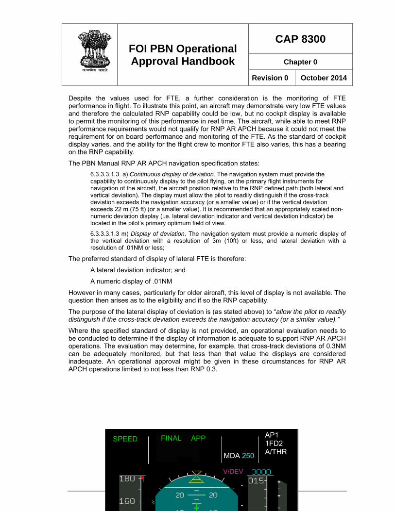
FOI PBN Operational Approval Handbook
CAP 8300
Chapter 0
Revision 0 October 2014
106
Despite the values used for FTE, a further consideration is the monitoring of FTE performance in flight. To illustrate this point, an aircraft may demonstrate very low FTE values and therefore the calculated RNP capability could be low, but no cockpit display is available to permit the monitoring of this performance in real time. The aircraft, while able to meet RNP performance requirements would not qualify for RNP AR APCH because it could not meet the requirement for on board performance and monitoring of the FTE. As the standard of cockpit display varies, and the ability for the flight crew to monitor FTE also varies, this has a bearing on the RNP capability.
The PBN Manual RNP AR APCH navigation specification states: 6.3.3.3.1.3. a) Continuous display of deviation. The navigation system must provide the capability to continuously display to the pilot flying, on the primary flight instruments for navigation of the aircraft, the aircraft position relative to the RNP defined path (both lateral and vertical deviation). The display must allow the pilot to readily distinguish if the cross-track deviation exceeds the navigation accuracy (or a smaller value) or if the vertical deviation exceeds 22 m (75 ft) (or a smaller value). It is recommended that an appropriately scaled non-numeric deviation display (i.e. lateral deviation indicator and vertical deviation indicator) be located in the pilot’s primary optimum field of view.
6.3.3.3.1.3 m) Display of deviation. The navigation system must provide a numeric display of the vertical deviation with a resolution of 3m (10ft) or less, and lateral deviation with a resolution of .01NM or less;
The preferred standard of display of lateral FTE is therefore:
A lateral deviation indicator; and
A numeric display of .01NM
However in many cases, particularly for older aircraft, this level of display is not available. The question then arises as to the eligibility and if so the RNP capability.
The purpose of the lateral display of deviation is (as stated above) to “allow the pilot to readily distinguish if the cross-track deviation exceeds the navigation accuracy (or a similar value).”
Where the specified standard of display is not provided, an operational evaluation needs to be conducted to determine if the display of information is adequate to support RNP AR APCH operations. The evaluation may determine, for example, that cross-track deviations of 0.3NM can be adequately monitored, but that less than that value the displays are considered inadequate. An operational approval might be given in these circumstances for RNP AR APCH operations limited to not less than RNP 0.3.
V/DEV
SPEED FINAL
APP MDA 250
AP1 1FD2 A/THR
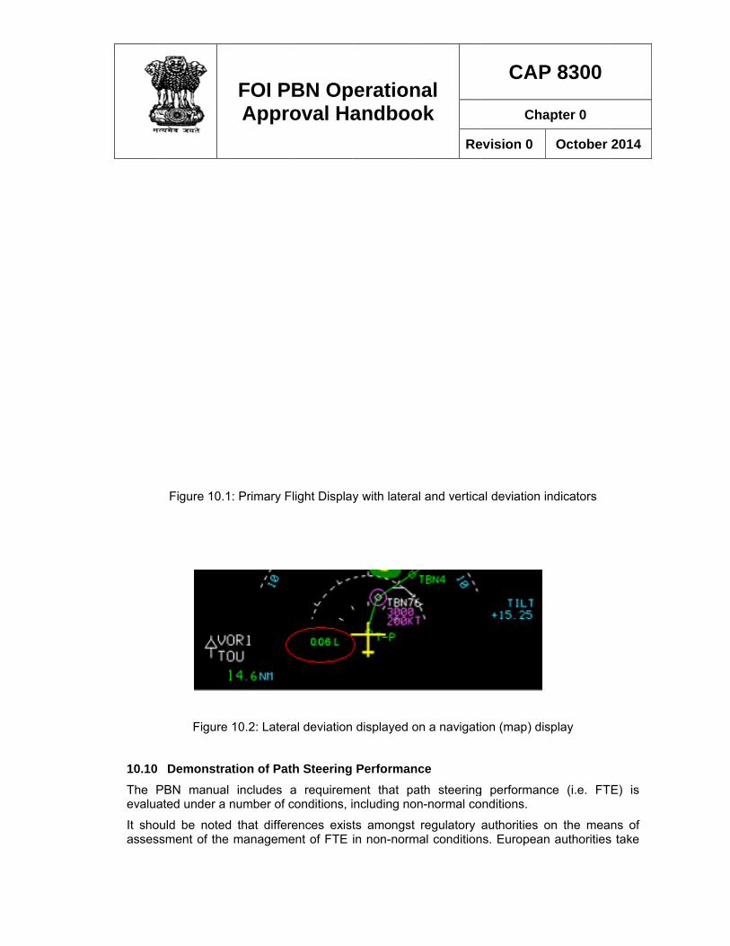
10.10 The Pevalua
It shoassess
Figure 10.
Figure
DemonstrPBN manuaated under a
uld be notesment of the
FOI PAppr
1: Primary F
e 10.2: Later
ration of Paal includes a number of
ed that differe managem
PBN Oproval Ha
Flight Displa
ral deviation
th Steeringa requiremconditions, i
rences existent of FTE
perationandboo
y with latera
displayed o
Performanment that pa
including no
ts amongst in non-norm
nal ok
Re
al and vertica
on a navigati
nce ath steeringn-normal co
regulatory mal condition
CAP
Cha
evision 0
al deviation i
ion (map) dis
g performanonditions.
authorities ons. European
P 8300
apter 0
October
indicators
splay
nce (i.e. FT
on the mean authorities
2014
TE) is
ans of s take
FOI PBN Operational Approval Handbook
CAP 8300
Chapter 0
Revision 0 October 2014
108
the view that the aircraft system should be capable of managing non-normal events, while the FAA considers that operational mitigations are acceptable.
The method(s) is used to demonstrate FTE performance must be taken into account when evaluating crew procedures.
10.11 Navigation System Monitoring and Alerting In order to qualify for RNP operations of any kind the navigation system must incorporate a system to monitor the performance of the navigation system and provide an alert to the flight crew when the system no longer meets the specified performance requirements.
Two elements of navigation system performance are normally monitored, accuracy and integrity.
Depending upon the manufacturer the parameters used and the alerting levels will vary, however the method used is not normally an issue with regard to aircraft eligibility, although there can be implications in operating procedures. Information should be obtained on the parameters that are monitored, the relevant alert limits and the method of annunciation of the alert.
Navigation system accuracy is commonly represented by Horizontal Figure of Merit (HFOM) or Estimated Position Error (EPE). These parameters represent an estimate of the position solution assuming that the satellite system is operating within its specific performance. An alert is normally generated when HFOM or EPE equals or exceeds a limit, normally 1 x RNP.
Integrity is commonly monitored by Horizontal Protection Level (HPL), sometimes called Horizontal Integrity Limit (HIL). An alert is provided when HPL equals of exceeds a limit relative to the selected RNP.
In at least one case the manufacturer derives a value for accuracy as a function of HPL. As both accuracy and integrity are dependent upon the same satellite constellation there is a relationship between derived parameters such as HFOM, EPE and HPL (HIL). Although each of these parameters measures different performance characteristics, each can be shown to be a function of another, within specified bounds.
Normally NSE integrity is monitored, but some systems monitor both accuracy and integrity and separate alerting limits are set for each parameter. In some (less common) cases HFOM is used and there may be no alert directly related to integrity. Such cases warrant further examination to ensure that integrity is adequately monitored and it may be necessary to implement supplementary procedures (e.g. ground monitoring) to ensure that integrity is available for all operations.
10.12 GNSS latent failure protection GNSS systems must provide protection from latent GPS satellite failure. Protection is provided by an integrity monitoring system and the principles of integrity monitoring are discussed elsewhere in this handbook.
For RNP AR APCH operations the PBN Manual includes a requirement that when HIL = HAL that the probability that the aircraft remains within the obstacle clearance volume used to evaluate the procedure must be greater than 95 percent (both laterally and vertically). (Para 6.3.3.2.2 (b)). Normally the manufacturer will provide documentation that this condition is met.
FOI PBN Operational Approval Handbook
CAP 8300
Chapter 0
Revision 0 October 2014
109
An alternative means of compliance provided in the note attached to this paragraph is available if the HIL is less than 2 x RNP less 95% FTE.
It may be helpful to consider a typical case based upon the simple (alternative) case. The typical 95% FTE for a modern aircraft with AP engaged is of the order of .07NM/95%. To meet the alternative means of compliance HIL should not exceed 2 x RNP - .07NM. For the limiting case (currently) where RNP = 0.10NM, the maximum HIL is:
(2 x 0.10) - .07 = 0.13NM.
In most cases, HAL ≤ 1 x RNP and therefore this condition is met.
10.13 Operating Procedures In recent years most manufacturers have developed recommendations for RNP AR APCH operating procedures. Although the manufacturer recommendations should be followed, the operational approval should include an independent evaluation of the operators’ proposed procedures. RNP AR APCH operating procedures should be consistent with the operator’s normal procedures where possible in order to minimise any human factors elements associated with the introduction of RNP AR APCH operations.
Vectoring. A procedure may be intercepted at a position inside the IAF but no later than the VIP when vectored by ATS. Descent on an approach procedure below the minimum vectoring altitude is not permitted until the aircraft is established within the vertical and lateral tolerances of the procedure and the appropriate navigation mode(s) is engaged.
10.14 RNP Availability Prediction. As the current GPS constellation is unable to provide 100% availability of RNP at all levels of service, there a periods, depending upon a number of factors, when an RNP approach cannot be conducted. Consequently a prediction of availability is conducted to enable the flight crew and dispatchers (where applicable) to take into consideration the level of RNP capability that can be expected at any particular location.
Commonly, even for low RNP levels, the periods when an RNP service is unavailable are short, and a delay in departure or en-route, is often sufficient to schedule an arrival when the service is predicted to be available.
An operation is not available, or should be discontinued when an alert is displayed to the flight crew. Consequently availability is determined by the means used to generate an alert, which as discussed previously, varies between aircraft. In order to be most accurate and effective a prediction of availability needs to be based on the same parameters that are used in the particular aircraft systems, rather than a general prediction of a parameter such as HPL.
The operator needs to make arrangements for prediction service to be available that replicates the monitoring system on the aircraft. Prediction services are readily available from a number of commercial sources. The prediction should be based on the latest satellite health data, which is readily available, and take into account other factors such as high terrain. On board prediction programs are generally unsatisfactory in that they are unable to take account of satellite NOTAMS and terrain masking.
While satellite prediction services are normally accurate and reliable it should be noted that an unpredicted unavailability can occur at any time. However safety is not compromised
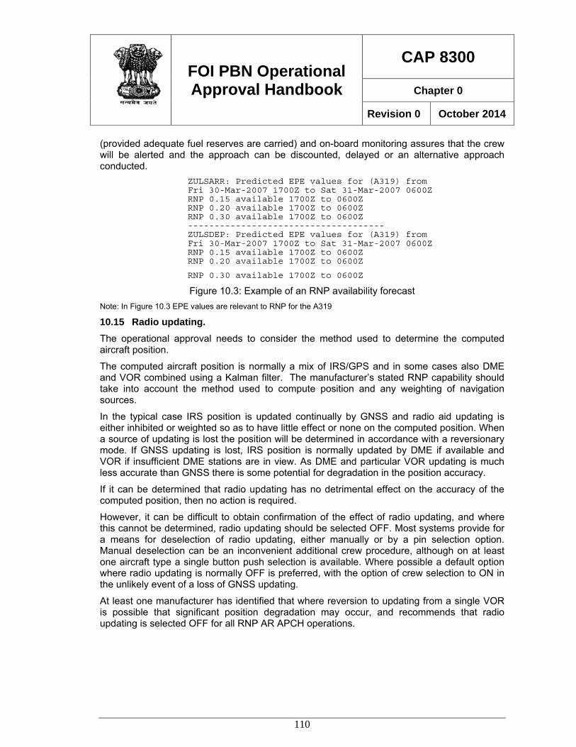
FOI PBN Operational Approval Handbook
CAP 8300
Chapter 0
Revision 0 October 2014
110
(provided adequate fuel reserves are carried) and on-board monitoring assures that the crew will be alerted and the approach can be discounted, delayed or an alternative approach conducted.
ZULSARR: Predicted EPE values for (A319) from Fri 30-Mar-2007 1700Z to Sat 31-Mar-2007 0600Z RNP 0.15 available 1700Z to 0600Z RNP 0.20 available 1700Z to 0600Z RNP 0.30 available 1700Z to 0600Z ------------------------------------- ZULSDEP: Predicted EPE values for (A319) from Fri 30-Mar-2007 1700Z to Sat 31-Mar-2007 0600Z RNP 0.15 available 1700Z to 0600Z RNP 0.20 available 1700Z to 0600Z
RNP 0.30 available 1700Z to 0600Z
Figure 10.3: Example of an RNP availability forecast Note: In Figure 10.3 EPE values are relevant to RNP for the A319
10.15 Radio updating. The operational approval needs to consider the method used to determine the computed aircraft position.
The computed aircraft position is normally a mix of IRS/GPS and in some cases also DME and VOR combined using a Kalman filter. The manufacturer’s stated RNP capability should take into account the method used to compute position and any weighting of navigation sources.
In the typical case IRS position is updated continually by GNSS and radio aid updating is either inhibited or weighted so as to have little effect or none on the computed position. When a source of updating is lost the position will be determined in accordance with a reversionary mode. If GNSS updating is lost, IRS position is normally updated by DME if available and VOR if insufficient DME stations are in view. As DME and particular VOR updating is much less accurate than GNSS there is some potential for degradation in the position accuracy.
If it can be determined that radio updating has no detrimental effect on the accuracy of the computed position, then no action is required.
However, it can be difficult to obtain confirmation of the effect of radio updating, and where this cannot be determined, radio updating should be selected OFF. Most systems provide for a means for deselection of radio updating, either manually or by a pin selection option. Manual deselection can be an inconvenient additional crew procedure, although on at least one aircraft type a single button push selection is available. Where possible a default option where radio updating is normally OFF is preferred, with the option of crew selection to ON in the unlikely event of a loss of GNSS updating.
At least one manufacturer has identified that where reversion to updating from a single VOR is possible that significant position degradation may occur, and recommends that radio updating is selected OFF for all RNP AR APCH operations.
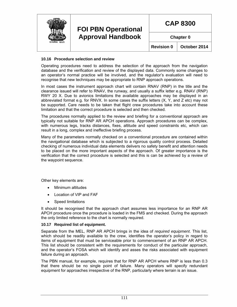
FOI PBN Operational Approval Handbook
CAP 8300
Chapter 0
Revision 0 October 2014
111
10.16 Procedure selection and review Operating procedures need to address the selection of the approach from the navigation database and the verification and review of the displayed data. Commonly some changes to an operator’s normal practice will be involved, and the regulator’s evaluation will need to recognise that new techniques may be appropriate to RNP approach operations.
In most cases the instrument approach chart will contain RNAV (RNP) in the title and the clearance issued will refer to RNAV, the runway, and usually a suffix letter e.g. RNAV (RNP) RWY 20 X. Due to avionics limitations the available approaches may be displayed in an abbreviated format e.g. for RNVX. In some cases the suffix letters (X, Y, and Z etc) may not be supported. Care needs to be taken that flight crew procedures take into account these limitation and that the correct procedure is selected and then checked.
The procedures normally applied to the review and briefing for a conventional approach are typically not suitable for RNP AR APCH operations. Approach procedures can be complex, with numerous legs, tracks distances, fixes, altitude and speed constraints etc, which can result in a long, complex and ineffective briefing process.
Many of the parameters normally checked on a conventional procedure are contained within the navigational database which is subjected to a rigorous quality control process. Detailed checking of numerous individual data elements delivers no safety benefit and attention needs to be placed on the more important aspects of the approach. Of greater importance is the verification that the correct procedure is selected and this is can be achieved by a review of the waypoint sequence.
Other key elements are:
• Minimum altitudes
• Location of VIP and FAF
• Speed limitations
It should be recognised that the approach chart assumes less importance for an RNP AR APCH procedure once the procedure is loaded in the FMS and checked. During the approach the only limited reference to the chart is normally required.
10.17 Required list of equipment. Separate from the MEL, RNP AR APCH brings in the idea of required equipment. This list, which should be readily available to the crew, identifies the operator’s policy in regard to items of equipment that must be serviceable prior to commencement of an RNP AR APCH. This list should be consistent with the requirements for conduct of the particular approach, and the operator’s FOSA which will identify and asses the risks associated with equipment failure during an approach.
The PBN manual, for example, requires that for RNP AR APCH where RNP is less than 0.3 that there should be no single point of failure. Many operators will specify redundant equipment for approaches irrespective of the RNP, particularly where terrain is an issue.
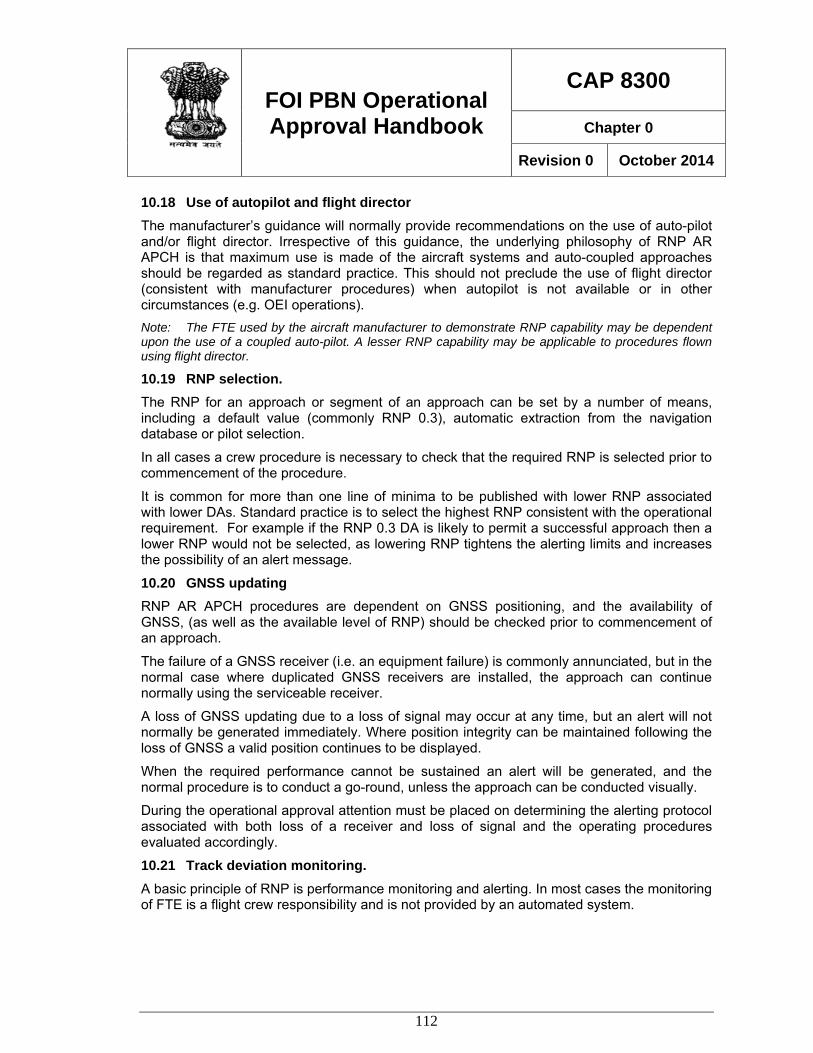
FOI PBN Operational Approval Handbook
CAP 8300
Chapter 0
Revision 0 October 2014
112
10.18 Use of autopilot and flight director The manufacturer’s guidance will normally provide recommendations on the use of auto-pilot and/or flight director. Irrespective of this guidance, the underlying philosophy of RNP AR APCH is that maximum use is made of the aircraft systems and auto-coupled approaches should be regarded as standard practice. This should not preclude the use of flight director (consistent with manufacturer procedures) when autopilot is not available or in other circumstances (e.g. OEI operations). Note: The FTE used by the aircraft manufacturer to demonstrate RNP capability may be dependent upon the use of a coupled auto-pilot. A lesser RNP capability may be applicable to procedures flown using flight director.
10.19 RNP selection. The RNP for an approach or segment of an approach can be set by a number of means, including a default value (commonly RNP 0.3), automatic extraction from the navigation database or pilot selection.
In all cases a crew procedure is necessary to check that the required RNP is selected prior to commencement of the procedure.
It is common for more than one line of minima to be published with lower RNP associated with lower DAs. Standard practice is to select the highest RNP consistent with the operational requirement. For example if the RNP 0.3 DA is likely to permit a successful approach then a lower RNP would not be selected, as lowering RNP tightens the alerting limits and increases the possibility of an alert message.
10.20 GNSS updating RNP AR APCH procedures are dependent on GNSS positioning, and the availability of GNSS, (as well as the available level of RNP) should be checked prior to commencement of an approach.
The failure of a GNSS receiver (i.e. an equipment failure) is commonly annunciated, but in the normal case where duplicated GNSS receivers are installed, the approach can continue normally using the serviceable receiver.
A loss of GNSS updating due to a loss of signal may occur at any time, but an alert will not normally be generated immediately. Where position integrity can be maintained following the loss of GNSS a valid position continues to be displayed.
When the required performance cannot be sustained an alert will be generated, and the normal procedure is to conduct a go-round, unless the approach can be conducted visually.
During the operational approval attention must be placed on determining the alerting protocol associated with both loss of a receiver and loss of signal and the operating procedures evaluated accordingly.
10.21 Track deviation monitoring. A basic principle of RNP is performance monitoring and alerting. In most cases the monitoring of FTE is a flight crew responsibility and is not provided by an automated system.
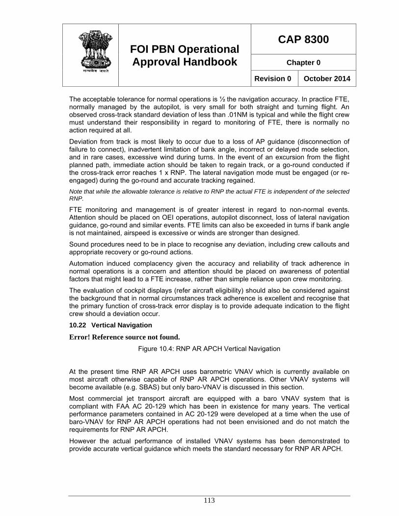
FOI PBN Operational Approval Handbook
CAP 8300
Chapter 0
Revision 0 October 2014
113
The acceptable tolerance for normal operations is ½ the navigation accuracy. In practice FTE, normally managed by the autopilot, is very small for both straight and turning flight. An observed cross-track standard deviation of less than .01NM is typical and while the flight crew must understand their responsibility in regard to monitoring of FTE, there is normally no action required at all.
Deviation from track is most likely to occur due to a loss of AP guidance (disconnection of failure to connect), inadvertent limitation of bank angle, incorrect or delayed mode selection, and in rare cases, excessive wind during turns. In the event of an excursion from the flight planned path, immediate action should be taken to regain track, or a go-round conducted if the cross-track error reaches 1 x RNP. The lateral navigation mode must be engaged (or re-engaged) during the go-round and accurate tracking regained. Note that while the allowable tolerance is relative to RNP the actual FTE is independent of the selected RNP.
FTE monitoring and management is of greater interest in regard to non-normal events. Attention should be placed on OEI operations, autopilot disconnect, loss of lateral navigation guidance, go-round and similar events. FTE limits can also be exceeded in turns if bank angle is not maintained, airspeed is excessive or winds are stronger than designed.
Sound procedures need to be in place to recognise any deviation, including crew callouts and appropriate recovery or go-round actions.
Automation induced complacency given the accuracy and reliability of track adherence in normal operations is a concern and attention should be placed on awareness of potential factors that might lead to a FTE increase, rather than simple reliance upon crew monitoring.
The evaluation of cockpit displays (refer aircraft eligibility) should also be considered against the background that in normal circumstances track adherence is excellent and recognise that the primary function of cross-track error display is to provide adequate indication to the flight crew should a deviation occur.
10.22 Vertical Navigation
Error! Reference source not found. Figure 10.4: RNP AR APCH Vertical Navigation
At the present time RNP AR APCH uses barometric VNAV which is currently available on most aircraft otherwise capable of RNP AR APCH operations. Other VNAV systems will become available (e.g. SBAS) but only baro-VNAV is discussed in this section.
Most commercial jet transport aircraft are equipped with a baro VNAV system that is compliant with FAA AC 20-129 which has been in existence for many years. The vertical performance parameters contained in AC 20-129 were developed at a time when the use of baro-VNAV for RNP AR APCH operations had not been envisioned and do not match the requirements for RNP AR APCH.
However the actual performance of installed VNAV systems has been demonstrated to provide accurate vertical guidance which meets the standard necessary for RNP AR APCH.
FOI PBN Operational Approval Handbook
CAP 8300
Chapter 0
Revision 0 October 2014
114
It is therefore necessary to obtain data to substantiate the VNAV performance. The basis of the procedure design is the VEB which in comprised of the following elements:
• Altimetry System Error (ASE)
• Flight Technical Error (FTE)
• Horizontal coupling or Actual Navigation Performance Error (ANPE)
• Waypoint resolution error (WPR)
• Vertical angle error (VAE)
• Atis Error
The VEB is computed using the following formula:
ATISVAEASEFTEWPRANPEISADBGVEB +++++++= 22222
34
Where :
BG is Body Geometry (allowance for wing span during turning flight)
ISAD is ISA Deviation which is the allowance for temperature effect
ANPE, WPR and ATIS errors are either fixed or independent of the aircraft. The elements that need to be evaluated are:
Altimetry system error (ASE);
Flight technical error
Vertical angle error
ASE should be determined by the manufacturer and documentation provided to show that the aircraft meets the minimum requirement; The 99.7% altimetry system error for each aircraft (assuming the temperature and lapse rates of the ISA) shall be less or equal to than the following with the aircraft in the approach configuration: ASE = -8.8 x 10⁻⁸ x H2 + 6.5 x10⁻³ x H + 50 (ft)
Where H is the true altitude of the aircraft.
This information may be obtained from the manufacturers in most cases, or from other regulatory authorities that have conducted an operational approval for the particular aircraft. Where insufficient data exists, in-service data can be collected using on-board engineering or QAR data collection, during the initial implementation period.
Aircraft which are RVSM compliant should have no difficulty in meeting the ASE requirement.
The value for FTE used in the calculation of VEB is 23m (75ft)/ 99.7% (3σ ) and it needs to be established that the aircraft can meet this requirement. Most manufacturers will provide a
FOI PBN Operational Approval Handbook
CAP 8300
Chapter 0
Revision 0 October 2014
115
statement that the FTE/99.7% is less than this value, and performance is typically of the order of 50 – 60 ft. Where the manufacturer supplied data is unavailable, insufficient on inconclusive, the FTE values can be substantiated during initial operations by collecting on-board data from the engineering monitoring system or QAR. Operations may need to be limited to a high minima or visual conditions during the data collection periods.
Vertical angle error is a value normally set by the FMS manufacturer, and should be equal or less than 0.01°. As many FMSs were designed when there was no requirement for such as accurate definition of vertical flight path angle, the value could be as high as 0.1°. This of itself does not mean that the aircraft is unable to qualify as the VEB is a sum of all the contributing errors. An analysis of the sum of all the errors, including a high value of vae should demonstrate that the VEB remains with in the design limit.
10.23 Vertical deviation monitoring. Although variations in FTE are accommodated in the VEB, it is a flight crew responsibility to monitor FTE and limit any excursions above and below the vertical flight path.
Most aircraft do not have a system for automatic monitoring and/or alerting of deviation from the vertical flight path and this function is a crew responsibility. The maximum acceptable deviation below the flight path is set at 23m (75ft). Crew procedures must detail the callouts required when a deviation is observed, and mandate a go-round if the deviation exceeds the maximum. Deviations above the flight path do not compromise obstacle clearance in the final approach, but can result in the aircraft arriving above the flight path, leading to destabilisation of the approach, a long landing, energy management issues and other effects. Sustained deviation above the flight path should be limited to less than 75ft.
During the evaluation of the aircraft systems attention should be placed on the vertical flight path and deviation displays which need to be adequate to allow flight crew monitoring of flight path deviations.
Although the design of an RNP AR APCH procedure uses the VEB obstacle clearance only in the final approach segment, it is operationally convenient to nominate a point prior to the FAF at which the aircraft is to be established on the lateral and vertical flight path, with the appropriate flight mode engaged (e.g. VNAV PATH or FINAL APP) in a suitable approach configuration, and in stable flight. Although various terms have been used for this point, Vertical Intercept Point (VIP) is becoming accepted in common use. This is also useful to indicate to ATC the latest point at which the approach can be joined if it is necessary to take the aircraft off-track after the IAF.
10.24 Maximum airspeeds As the ability for an aircraft to remain on track during an RF leg is limited by angle of bank and groundspeed, it is important that the operational approval addresses both the aircraft capability and the flight crew responsibilities associated with this common manoeuvre.
Bank angle authority is subject to a number of factors including crew selection, airspeed, altitude, ground proximity, loss of systems (e.g. RADALT) and can result in an unplanned reduction of commanded bank angle leading to a deviation from track.
The minimum radius for an RF legs is determined by the assumed maximum bank angle (25°/ 8° above/below 121m (400ft) respectively) at the maximum design ground speed. The
FOI PBN Operational Approval Handbook
CAP 8300
Chapter 0
Revision 0 October 2014
116
maximum groundspeed is a function of the assumed maximum true airspeed, (which is affected by altitude and temperature) and an assumed rare normal tailwind component. In normal operations, as flight is well within the maximum limits (i.e. light winds) observed bank angles are low. However should design rare normal tailwind conditions exist, and/or the maximum design airspeed is reached or exceeded, then the aircraft will command up to the maximum bank angle in order stay on the flight path. If the bank angle is reached, any further increase in groundspeed will result in a deviation from the flight path.
It is necessary that flight crews understand the effect of airspeed on track keeping in RF turns and limit speeds to the maximum used in design. The design airspeeds used for various phases of flight and aircraft category are published in the PBN Manual. Maximum airspeeds may also be programmed in the navigation database enabling less reliance on flight crew memory to manage airspeed.
Although not a mandatory function for RNP AR APCH the capability to fly an RF leg is commonly required for RNP AR APCH procedures. Consequently it is unusual for an operational approval to not cover operations with RF legs.
10.25 Limiting temperature Obstacle clearance in the final approach segment is adjusted to allow for the change in flight path with temperature. In temperatures below ISA the actual vertical flight path is flatter than the nominal designed gradient and obstacle clearance is reduced. The procedure designer, in order to maintain minimum clearance from obstacles beneath the final approach path, may need to limit the operating temperature, and a minimum temperature is published on the approach chart.
Some aircraft systems incorporate a temperature compensation system which allows the design flight path gradient to be flown, removing the requirement to protect the final approach path from the effect of temperature. However the majority of air transport aircraft do not have temperature compensation installed. Note: Some operations also incorporate provision for non-normal operations, and temperature limits may also be predicated on OEI climb performance.
10.26 Altimeter setting procedures As the flight path guidance provided by a barometric VNAV system is directly affected by the barometric pressure subscale setting, particular attention needs to be placed to pressure setting procedures and associated aircraft systems.
10.27 TOGA Navigation Functionality The Take-off Go Around (TOGA) function in most existing aircraft installations was designed to assist in the conduct of a missed approach in circumstances where the general requirement is to maintain the approach track during the missed approach. For RNP AR APCH operations this typical functionality is no longer an appropriate solution and the PBN Manual requirement is that missed approach guidance is provided such that continual lateral navigation guidance is provided in the go-round. The terms TOGA to LNAV, or TOGA to NAV describe this functionality in common usage.
This feature is becoming standard on production aircraft and is available as an upgrade on many later model aircraft. Where the function is not available, special crew procedures and
FOI PBN Operational Approval Handbook
CAP 8300
Chapter 0
Revision 0 October 2014
117
training may be developed to overcome this limitation. Normally it will be necessary to over-ride the normal TOGA track hold function and manually maintain the RNP track until the normal RNP navigation can be re-engaged.
10.28 Navigation Database The PBN Manual includes a number of requirements associated with the navigation database as follows:
Data management process: Operators who are experienced in RNAV operations are likely to have sound procedures in place for the management of data. Less experienced operators may not fully understand the need for comprehensive management procedures and may need to develop or improve existing procedures.
Data Suppliers: The requirement for a data supplier to have an approval in accordance with RTCA DO200A/Eurocae ED76 is now common practice. It is common for States to recognise a LoA issued by the State where the data base supplier is located. It should be noted that despite the requirement for a LoA that data errors may still occur and dependence on quality management alone is not sufficient.
Initial Data Validation: The procedure designer is required conduct an initial flight validation in an RNP capable aircraft. Experience has been that despite the validity of the data originating in the design office errors can occur downstream in data packing, reading and interpreting of data, data execution and functionality, and it is necessary for each operator to conduct an initial data validation to ensure correct operation in the particular type/model of aircraft to be flown.
While this requirement is necessary it can present problems in practice. If the validation is to be done in a simulator, then the simulator should accurately replicate the aircraft. In many cases this is not possible as simulators tend to lag behind aircraft in terms of upgrades. Consideration may need to be made for the simulator compatibility, complexity of the procedure, past experience and other factors. If a suitable simulator is not available then validation may need to be conducted in the aircraft. This can be achieved with safety in visual conditions during normal revenue operations without incurring additional unnecessary expense.
Cyclic Data Validation: This is an important consideration in the management of navigation data as each update provides a subtle opportunity for data errors to occur. Various methods are used in an attempt to ensure that data remains valid, but the most reliable method involves an electronic comparison of the new database against a database of known validity. For this process to be successful, source data in electronic form is necessary, although most States have yet to implement facilities to enable the export of procedures in an electronic file. (Note: The file should be derived directly from the procedure designers electronic data file without human intervention.).
Data Updates: Changes are routinely made to all approach procedures and unless there is a significant change to the flight path, either laterally or vertically, re-validation should not be necessary. The cyclic comparison of new versus old data must be designed to identify changes that have not been ordered prior to the effective date for each database cycle. Action can then be taken to rectify the problem before the effective date, or issue corrective action such as notices to flight crew, withdrawal of procedures etc.
FOI PBN Operational Approval Handbook
CAP 8300
Chapter 0
Revision 0 October 2014
118
In cases where an effective electronic cyclic data validation process is not available, it may be necessary to conduct re-validation of procedures at each cycle. This is a time-consuming and complex procedure which should be avoided wherever possible.
10.29 Flight crew training Properly conducted RNP AR APCH operations are perhaps the simplest yet most efficient approach operation available. The fact that normal operations, routinely conducted using the aircraft auto-flight system, provide excellent repeatable and very accurate flight path guidance can mislead operators into a false sense of security.
It must be recognised that the improvements in operational capability and efficiency need to be matched by an enhanced awareness and sound operating procedures. One of the subtle risks to RNP AR APCH operations is the reduced levels of alertness that may occur simply due to the confidence that crews have in the operation.
Thorough flight crew training is essential to ensure that crews are fully conversant with the aircraft systems and operations and are able to manage all normal and non-normal operations with confidence. Training needs to emphasise the role of the flight crew to monitor the aircraft systems and a thorough understanding of aircraft systems management.
Training requirements will vary significantly depending on the operator’s previous experience. Operators familiar with the conduct of RNP APCH (RNAV GNSS) operations will find the transition to RNP AR APCH less demanding. Operators without relevant experience would be well advised to progress slowly and introduce RNP AR APCH operations under a phased implementation program.
As a guide, crews with previous relevant RNAV approach experience will typically require a minimum of one day ground briefing on RNP AR APCH principles, systems and operating procedures, and one or more 4hr simulator training sessions (per crew).
10.30 Flight Operational Safety Assessment (FOSA) The improved capability of RNP AR APCH operations enables approach procedures to be designed to low decision altitudes at locations where conventional approach procedures are not possible. The ability to deliver an aircraft to a DA as low as 75m/250ft in close proximity to terrain brings with it increased exposure to risk in the event of a critical systems failure.
The safety of normal RNP AR APCH operations is not in question, and compliance with the requirements of the RNP AR APCH navigation specification is regarded as sufficient to meet the required level of safety. The FOSA is intended to provide assurance that the level of safety is maintained in the event of a non-normal event.
ICAO instrument approach procedure design criteria do not make provision for non-normal events and consequently approach procedures are designed without regard to the consequences of failures, and could therefore place an aircraft in a situation where there is increased exposure to risk in the event of a system failure.
FOI PBN Operational Approval Handbook
CAP 8300
Chapter 0
Revision 0 October 2014
119
While there are elements of an approach procedure that are associated with the air navigation service provider, the aircraft manufacturer, and the procedure designer, the fundamental responsibility for the FOSA rests with the operator.
The method used to conduct the FOSA is of less importance that the fact that an assessment of the hazards is conducted. There are generally accepted practices for risk assessment adopted by a number of industries which can be applied to the FOSA.
In general, the following basic principles should be applied.
1. Each of the hazards should be identified. Guidance on typical hazards is provided in the PBN Manual, but this list should not be regarded as exhaustive.
2. The probability of a hazard event occurring should be assessed. For example, probability may be assessed as:

FOI PBN Operational Approval Handbook
CAP 8300
Chapter 0
Revision 0 October 2014
120
a. Almost certain
b. Likely
c. Possible
d. Unlikely
e. Rare
f. Extremely Rare
3. Assess the consequences of each event, for example:
a. Minor
b. Moderate
c. Major
d. Severe
e. Catastrophic
4. Identify risk mitigators (including documentation)
5. Evaluate the overall risk
At the end of this process all risk outcomes should be assessed as low or “as low as reasonably practical”.
For example:
Hazard: Loss of integrity during an approach with RF legs
Probability: Rare
Consequences: Minor (Go-round, IRS nav available)
Risk mitigators: Availability prediction, TOGA to LNAV available, crew training
References: OPS Manual Section 5 Ch 2 RNP availability program
Fight crew operations manual Part II Section 3 para 7.4.3.1
Flight crew training Manual Section4 Chapter 1 para 1.9.3
Risk Assessment: Low