canso educational booklet unstable approaches 2nd … · global atm performance. canso – the...
TRANSCRIPT

Unstable ApproachesATC Considerations
Published: January 2011
TRANSFORMINGGLOBAL ATM PERFORMANCE
CANSO – the Civil Air Navigation Services Organisation
2
CANSO wishes to thank all contributors to this CANSO Educational Booklet and acknowledges the intellectual
property rights of those who have contributed to this document.
CANSO Copyright. All rights reserved. No part of this publication may be reproduced, or transmitted in any
form, without the prior permission of CANSO.
The Educational Booklet, which addresses Air Traffic Control Considerations for Unstable Approach is intended
to provide guidance to assist in the improvement of runway safety. CANSO has endeavoured to ensure the
accuracy of this Educational Booklet insofar as possible. However, all recommendations are made in the context
of a framework-based approach and without any guarantee on the part of the contributors or CANSO to
particular situations. CANSO disclaims any liability in connection with the use of this Educational Booklet or any
aspect thereof.
The Educational Booklet has been developed through the contributions of CANSO Members: UK-NATS, FAA-ATO
Unstable Approaches – ATC Considerations
3
1. Introduction An aircraft must meet certain criteria on approach to be able to land safely. This is because an aircraft in flight,
and in particular a large aircraft, possesses a great deal of energy that must be dissipated appropriately during
descent, landing and rollout. Managing an aircraft during the descent and approach phases essentially
becomes a task of managing energy, which is provided by aircraft speed and level. Landing long or a landing at
excessive speeds can result in an overrun. Excessive sink rates on approach whilst attempting to capture a glide
path can result in a hard landing or even Controlled Flight Into Terrain (CFIT). The criteria for continuing an
approach generally relates to the aircraft’s position, height, speed and configuration and should be outlined in
an airline’s Operations Manual. For each performance criterion, such as speed, rate of descent etc the aircraft
must be within a certain tolerable ‘window’ in order for it to be classified as “stabilised” and continue to land.
These criteria are assessed at “gates” which tend to be established, depending on individual Airline SOPs and
flight conditions, between 1500ft – 500ft agl. (Find descriptions of typical “window” criteria in Annex A).
Should the aircraft fail to meet these criteria it is considered to be unstable and a pilot should be expected to
execute a go-around. If an aircraft does not meet the conditions of the gate criteria and proceeds beyond the
gate altitude, then the occurrence is often automatically logged by the aircraft’s on-board information
monitoring system (Flight Data Monitoring) and the airline operator informed. The pilot can then expect to be
interviewed and potentially face disciplinary action. Although the approach’s stability is only officially
“measured” (against the criteria) when the aircraft passes through the above gates an unstable approach is
usually the result of a series of events involving various causal factors (weather, tailwind, fatigue, pressure,
workload, poor planning, pilot error, ATC interaction, procedures etc.), which can occur at any stage of the
approach, even as far back as the cruise phase.
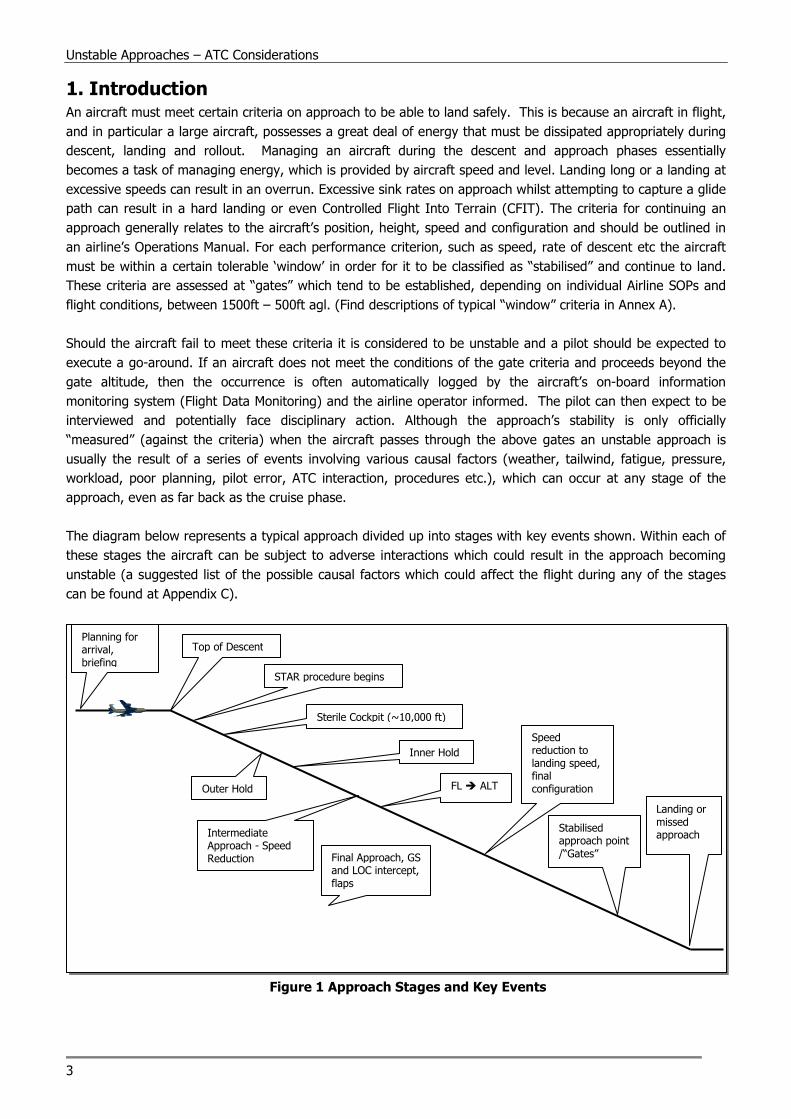
The diagram below represents a typical approach divided up into stages with key events shown. Within each of
these stages the aircraft can be subject to adverse interactions which could result in the approach becoming
unstable (a suggested list of the possible causal factors which could affect the flight during any of the stages
can be found at Appendix C).
Figure 1 Approach Stages and Key Events
Top of Descent
STAR procedure begins
Sterile Cockpit (~10,000 ft)
Outer Hold
Inner Hold
Intermediate Approach - Speed Reduction
FL � ALT
Final Approach, GS and LOC intercept, flaps
Speed reduction to landing speed, final configuration
Planning for arrival, briefing
Stabilised approach point /“Gates”
Landing or missed approach
CANSO – the Civil Air Navigation Services Organisation
4
Pilots are under pressure to achieve a stabilised approach for a number of reasons:
• Safety: unstable approaches have either directly or indirectly been the cause of several incidents and
accidents including Runway Excursions;
• Economic: a missed approach can eliminate all profit from a flight. Due to fuel constraints it may also
result in a diversion to an alternate aerodrome1.
• Legal: recent changes in legislation (within Europe EU Ops have replaced JAR OPS 1, which now trumps
any national law) which stipulates that stabilised approaches are mandated.
Ultimately it remains the responsibility of the Pilot in Command to decide not to continue an approach if, in their
opinion, the approach is becoming unstable. This decision can be made at any point during the approach and
not just at the Stabilised Approach decision point. Nevertheless, in the chain of events that lead up to an
unstable approach Air Traffic Control (ATC) can play a role.
1.1 Objectives
The purpose of this information is to increase the knowledge of Air Traffic Control Officers (ATCO) about
stabilised approaches and to increase their awareness of the part that ATC can have in contributing towards an
approach becoming unstable.
1.2 Limitations
It is recognised that many factors contribute towards unstable approaches and that the flight crew are
ultimately in control of the aircraft, however this document predominately focuses on the proposed ATC
contribution towards an unstable approach. Flight crew issues such as competence, training and CRM are not
covered. However, a list of causal factors, some without any ATC involvement are included (see Appendix C) so
that ATC staff have an awareness of the additional factors that could be occurring during an approach, some of
which could lead to an unstable approach and/or a missed approach.
In this assessment the contributory causes towards unstable approaches have been considered from a generic
point of view but with an emphasis on turbojet/turbofan aircraft. The principles provided in this paper may not
apply to all aircraft and airline operating procedures.
2. ATC Involvement in Unstable Approaches This section looks at the role that ATC can have in contributing to unstable approaches and discusses potential
solutions from an ATC point of view. The premise of this assessment is that ATC can contribute towards
unstable approaches through their involvement in and understanding of the following basic factors:
• Distance (Time) Provision
• Speed Instructions
For both of the above factors, two-way communication between ATC and the flight-deck plays a large and
important role. With good communication from both sides, the risk of an unstable approach occurring can be
significantly reduced.
1 An aircraft must typically carry sufficient fuel to fly to the primary (planned) destination, and then to an alternate destination. Failure to
land at the primary destination (unstable approach, bad weather, blocked runway etc.) may result in the primary fuel being used up,
leaving nothing but the diversion fuel in the tanks. In this case a diversion is mandatory. The only exception to this, under EU rules, is an
option for the crew to remain at destination if certain criteria are met and to burn off the diversion fuel (in this case the crew should inform
ATC that they are using their diversion fuel). In the latter case, if the aircraft reaches, or is anticipated to reach, its final reserve fuel then a
Mayday call is mandatory.

Unstable Approaches – ATC Considerations
5
2.1 Distance (Time) Provision
2.1.1 Descent Planning and ATC Routing
When operating piston and light turboprop aircraft descent planning is somewhat straightforward as these
aircraft operate at lower speeds and altitudes, and use propellers which add drag. Jet aircraft (and larger turbo
prop aircraft) have a very ‘clean’ design which offers minimal drag in order to achieve high cruising speeds.
Therefore jet aircraft often have a tendency to be ‘slippery’, i.e. they require a lot of distance to descend and/or
slow down. Further, jet aircraft operate at higher altitudes making the descent longer, which can compound
any errors. The whole situation is exacerbated by the use of modern high-bypass turbofan engines, which
produce a significantly higher residual thrust at flight-idle than older, low-bypass or pure turbojet, engines fitted
to the previous generation of jet aircraft.
Large aircraft are often fitted with a Flight Management System (FMS) which performs the descent calculations.
Based on the planned route the FMS continuously calculates and updates a vertical profile and a speed profile,
collectively referred to as a descent profile in this assessment. The vertical profile relates to the aircraft’s
planned level at any given point during the descent, and the speed profile relates to the target speeds for each
segment of the descent. The speed profile is calculated by a number of factors such as speed limits, wind and
Cost Index.2
With the necessary involvement of ATC instructions, the FMS calculated descent profile is not often flown. It is
therefore important that the flight crew keep a mental model (situational awareness) of the profile as the
constantly changing environment can quickly alter the remaining track mileage.
Descent planning for jet aircraft (including business jets, see Reference 4) is often based on a ‘three times’ rule
of thumb, or a variant thereof. As an example, with 100 nautical track miles remaining the aircraft should be at
approximately 30,000 ft on its descent profile. Extra distance is then added for deceleration. With larger
aircraft such as the B747 or A380, momentum plays a bigger role hence a longer distance for deceleration is
required. Other factors may also play a role during manual descent planning, such as speed instructions from
ATC, wind, and turbulence. A simplified example is shown in Figure 2 below. Note that the numbers used are
for illustration purposes only and will vary depending on aircraft type:
Figure 2 Descend Planning Example (Plan View)
2 The Cost Index (CI) is entered into the FMS and provides a speed versus economy ratio. The Cost Index usually ranges from 0 – 200. As an example, inputting a CI of 0 will yield the most economic flight, but at the lowest speeds. A CI of 200 would result in highest speeds, but also at the highest financial cost. The CI is calculated by the AO Ops department and input into the FMS before the flight departs.
50 nm
65 nm
30 nm A
15 nm
15 nm
B
C
ILS LOC

CANSO – the Civil Air Navigation Services Organisation
6
• Should the aircraft follow the planned route (A - B - C - Airport) the total track distance would be 110
miles. Assuming no wind the aircraft should aim to use perhaps 10 miles for decelerating and the
remaining 100 miles for descending, meaning that the aircraft should aim to be at approximately 30,000
ft at point A according to the ‘three times’ rule.
• Should ATC give the aircraft a shorter route at Point A (A - C - Airport) the total track miles would reduce
to 95 track miles. Assuming no wind the aircraft should aim to again use 10 miles for decelerating and
the remaining 85 miles for descending, meaning that the aircraft should aim to be at approximately
25,000 ft at point A according to the ‘three times’ rule. This means the aircraft would suddenly be 5,000
ft high on the ‘new’ descent profile.
Ideally descents usually take place with little or no thrust, hence immediate measures that are available to
‘catch’ the profile are speed brakes and increased speed (the effect of speed is discussed in further detail in
Section 2.2). Speed limits tend to apply at lower levels (e.g. 250 knots below FL100) and speed brakes often
become less effective as the aircraft decelerates. Hence towards the latter stages of the descent, drag may be
increased by early deployment of gear and flaps. However this is not a preferred option as it increases system
wear and may be inconsistent with local noise abatement procedures. Additionally, flap and gear deployment
are almost always associated with airframe speed restrictions and increases in fuel burn.
Although the FMS will automatically try to adjust the descent profile for alterations, a point can be reached
where the aircraft simply does not have sufficient distance to descend and decelerate. Failure of the flight crew
to anticipate ATC instructions and consequently alter the descent profile can result in the aircraft being too high
to make the approach.
Should this occur early in the approach the crew may request additional track miles. Should it occur late in the
approach the crew may well decide to execute a missed approach.
One of the most critical elements is to ensure that the crew receive regular and accurate updates of the
distance from touchdown (DFT) and is informed at the earliest opportunity of a change in routing; vectoring will
significantly alter the track miles. This is especially important for planning purposes if the track miles are being
reduced.
2.1.2 Approaches
2.1.2.1 Change of Runway
Prior to arrival a number of tasks must be accomplished on the flight-deck. As an example the flight-deck must
be configured for the approach, which would include setting all frequencies, minima, levels, speeds, routings
etc. Following this a briefing is required. Briefings are a component of Crew Resource Management (CRM) to
assure ‘transparency’ i.e. that all crew are working to the same plan for both normal and abnormal events and
will always include details of the Missed Approach Procedures (MAP) for the planned arrival runway. The crew
will also fly the approach expecting to “go-around” until the decision point (such as the Decision Altitude) at
which time they decide to land.
Prior to the approach, the setup and briefing tend to be conducted reasonably early, usually well before top of
descend. A late runway change may not only imply a different routing for the aircraft, but also that the flight
deck must be set up for a different approach on a different runway. This will require a new briefing and the
Flight Management Computer (FMC) to be reprogrammed. Therefore late runway changes tend to increase the
flight deck workload significantly during an already busy flight phase. This also applies to any changes to the
standard MAP which, if not as published, should be communicated to the flight crew as early as possible. It is
Unstable Approaches – ATC Considerations
7
reasonable to assume that errors are more likely to occur as the workload increases.
Runway changes that result in more track miles remaining are generally easier to cope with as they provide
additional time for the setup and briefing. With more track miles suddenly remaining the aircraft will be low on
the ‘new’ profile which can be compensated for by reducing the rate of descend. Further, a late change to a
parallel runway with the same type of approach tends to be easier to cope with as the descent profile remains
virtually the same and parallel runways often have the same MAP.
The most difficult runway change involves a change to a runway that results in less track miles remaining. As
an example, a late change from 09 to 27 for an aircraft coming in from the east will probably result in a rushed
setup and an abbreviated briefing and will, assuming the aircraft was on profile in the first place, suddenly put
the aircraft high on the ‘new’ profile. In these instances additional track miles will probably be required.
2.1.2.2 Change of Approach – Precision/Non-precision
There are fundamental differences in how different types of approaches are flown. The ILS is the most
common approach used at large airports. An ILS approach is usually flown at 3º and allows most aircraft to fly
a large part of the approach on autopilot. It also requires relatively little manipulation of the autopilot during
the approach; it is mainly speed reductions that take place to allow flaps and gear to be deployed. During an
ILS approach the aircraft will continue to slow down and configure after becoming established on both the
localiser and the glideslope. This means that the aircraft can maintain a relatively high speed until late in the
approach, such as 160knots until four miles. However, it is very difficult for a modern aircraft (A330, B-737-800,
etc) to descend on the glide slope and slow down simultaneously; therefore the controller must allow for
deceleration to final approach speed when the aircraft is approaching the glide slope interception point. Flight
crew requests for a slower airspeed during the final portion of the approach should be approved to the
maximum extent possible.
Non-precision approaches3 result in a much higher workload as in many cases, the crew must manually control
rate of descent or altitude. Although it can be flown on autopilot, more manipulation of the autopilot is
required as the crew must continuously adjust the rate of descent. The autopilot is usually disconnected earlier
compared to a precision approach as the decision point (Decision Altitude) is higher. Non-precision approaches
may be offset from the runway which requires an element of manual handling late in the approach, and as they
are not usually flown and practiced as frequently as precision approaches, it can result in the crew being less
proficient.
Controllers should be aware that due to the increased workload and constraints for the aircrew in flying a non-
precision approach (see 2.1.2.4), when vectoring onto finals and should aim to position the aircraft on finals at
a distance greater than normal, to assist the crew.
Note: PANS ATM does not differentiate on how a controller is expected to radar vector an aircraft to the final
approach course; the same procedure applies (30 degrees or less, 2 nm prior to G/S intercept…) for precision
or non-precision approaches. However, an awareness of flight crew workload can assist in reducing cockpit
workload.
Based on these challenges, non precision approaches tend to be carefully briefed. A fundamental difference
compared to a precision approach is speed management. As the speed changes during a non precision
approach, the pilot needs to recalculate and manually adjust the rate of descent in order to remain on the
3 ICAO assembly resolution A37-11 underpins the higher safety risks with non-precision operations and aims at having the availability of
approach procedures with vertical guidance to all runways
CANSO – the Civil Air Navigation Services Organisation
8
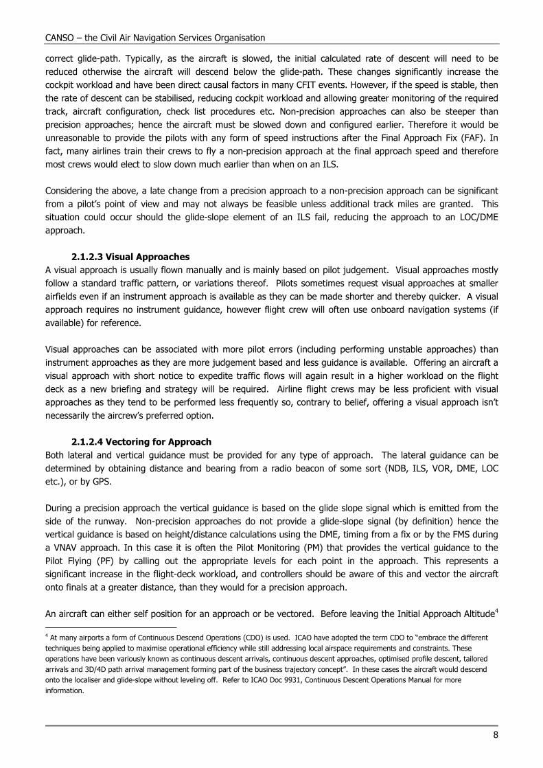
correct glide-path. Typically, as the aircraft is slowed, the initial calculated rate of descent will need to be
reduced otherwise the aircraft will descend below the glide-path. These changes significantly increase the
cockpit workload and have been direct causal factors in many CFIT events. However, if the speed is stable, then
the rate of descent can be stabilised, reducing cockpit workload and allowing greater monitoring of the required
track, aircraft configuration, check list procedures etc. Non-precision approaches can also be steeper than
precision approaches; hence the aircraft must be slowed down and configured earlier. Therefore it would be
unreasonable to provide the pilots with any form of speed instructions after the Final Approach Fix (FAF). In
fact, many airlines train their crews to fly a non-precision approach at the final approach speed and therefore
most crews would elect to slow down much earlier than when on an ILS.
Considering the above, a late change from a precision approach to a non-precision approach can be significant
from a pilot’s point of view and may not always be feasible unless additional track miles are granted. This
situation could occur should the glide-slope element of an ILS fail, reducing the approach to an LOC/DME
approach.
2.1.2.3 Visual Approaches
A visual approach is usually flown manually and is mainly based on pilot judgement. Visual approaches mostly
follow a standard traffic pattern, or variations thereof. Pilots sometimes request visual approaches at smaller
airfields even if an instrument approach is available as they can be made shorter and thereby quicker. A visual
approach requires no instrument guidance, however flight crew will often use onboard navigation systems (if
available) for reference.
Visual approaches can be associated with more pilot errors (including performing unstable approaches) than
instrument approaches as they are more judgement based and less guidance is available. Offering an aircraft a
visual approach with short notice to expedite traffic flows will again result in a higher workload on the flight
deck as a new briefing and strategy will be required. Airline flight crews may be less proficient with visual
approaches as they tend to be performed less frequently so, contrary to belief, offering a visual approach isn’t
necessarily the aircrew’s preferred option.
2.1.2.4 Vectoring for Approach
Both lateral and vertical guidance must be provided for any type of approach. The lateral guidance can be
determined by obtaining distance and bearing from a radio beacon of some sort (NDB, ILS, VOR, DME, LOC
etc.), or by GPS.
During a precision approach the vertical guidance is based on the glide slope signal which is emitted from the
side of the runway. Non-precision approaches do not provide a glide-slope signal (by definition) hence the
vertical guidance is based on height/distance calculations using the DME, timing from a fix or by the FMS during
a VNAV approach. In this case it is often the Pilot Monitoring (PM) that provides the vertical guidance to the
Pilot Flying (PF) by calling out the appropriate levels for each point in the approach. This represents a
significant increase in the flight-deck workload, and controllers should be aware of this and vector the aircraft
onto finals at a greater distance, than they would for a precision approach.
An aircraft can either self position for an approach or be vectored. Before leaving the Initial Approach Altitude4
4 At many airports a form of Continuous Descend Operations (CDO) is used. ICAO have adopted the term CDO to “embrace the different
techniques being applied to maximise operational efficiency while still addressing local airspace requirements and constraints. These
operations have been variously known as continuous descent arrivals, continuous descent approaches, optimised profile descent, tailored
arrivals and 3D/4D path arrival management forming part of the business trajectory concept”. In these cases the aircraft would descend
onto the localiser and glide-slope without leveling off. Refer to ICAO Doc 9931, Continuous Descent Operations Manual for more
information.

Unstable Approaches – ATC Considerations
9
(also known as Platform Altitude) the aircraft must be lined up with the runway and at an appropriate distance.
If the aircraft is not in the correct position the final descent can not be commenced as the aircraft may be
outside of the protected area, hence terrain separation can not be assured. A descent at this point would be
dangerous, particularly if in Instrument Meteorological Conditions.
Vectoring by ATC plays an important role in positioning an aircraft for an approach. The following two
examples show a reference scenario during which an aircraft is correctly vectored for a precision approach and
a scenario where unrealistic vectoring results in the aircraft either performing a missed approach and/or
becoming unstable.
Figure 3 Approach Vectoring (Reference Scenario)
In the correctly executed scenario the aircraft at Point A is vectored in for an approach, and is likely to intercept
the localiser before the glide-slope, or at least at the same time as the glide slope (Point B). In this case the
aircraft will intercept the glide-slope from below, which is preferred5. Provided that the aircraft has been
cleared for the approach it can safely descend on the glide-slope as it has both lateral and vertical guidance.
Basic aircraft instruments are shown, with the vertical bar on the dial showing the localiser, and the horizontal
bar showing the glide-slope.
The scenario shown in Figure 4 depicts the use of unrealistic vectors which result in the aircraft becoming
unstable causing it to either execute a missed approach or incorrectly continue the approach:
5 Catching the glide-slope from above is considered poor practice as a glide-slope may emit a ‘false’ glide-slope above the actual glide-slope.
The ‘false’ glide slope is steeper than the actual glide-slope and is not reliable.
Initial Approach Altitude e.g. 2,500 ft.
A
Equivalent Side View
Top View B
B
Glide-slope
Localiser C
A
C

CANSO – the Civil Air Navigation Services Organisation
10
Figure 4 Approach Vectoring (unrealistic Vectors)
The aircraft at Point D has been cut in short by ATC and has not yet arrived at the localiser. However it is
picking up the glide-slope signal as it is within range. As the aircraft moves closer to the runway the glide slope
indicator tells it to descend in accordance with the glide slope even if the aircraft has not arrived at the localiser
and therefore has no lateral guidance. The pilot must ignore this indication as descending would be unsafe.
Therefore the aircraft continues in level flight.
As the aircraft reaches Point E it finally picks up the localiser and now has both lateral and vertical guidance,
but is at this point very high on the glide slope and is unable to descend sufficiently to regain the glide-slope.
As the aircraft is already descending and probably also decelerating, increasing the rate of descent is difficult.
The aircraft should therefore execute a missed approach
Vectoring an aircraft in too short (as illustrated in Figure 4 above) should be avoided as it will probably lead to a
missed approach or excessive sink rates as the flight crew attempt to catch the glide-slope from above. An
approach with excessive sink rates is, by definition, an unstable approach (See Appendix A).
2.1.3 Descend Planning Requirements
For the crew to be able to adequately perform descent planning, at least one of the following is required:
• Adherence to the Flight Plan Route and Approach Procedure
• Local Knowledge of Potential Deviations
• Track Distance Information from the Approach Controller
To expect aircraft to always adhere to the planned route and approach procedure is impractical for ATC. Also,
all pilots will not have experience with local ATC procedures. Therefore the option that provides most flexibility
is provision of track distance information from the approach controller anytime the aircraft is deviated from the
planned route and approach procedure. These are discussed in further detail below:
2.1.3.1 Adherence to the Flight Plan Route and Approach Procedure
Based on the flight plan route a descent profile can be calculated by the FMS. If the aircraft adheres to the
planned route it should also adhere reasonably to the descent profile. Anytime ATC modifies the route some
form of compensation will be required, such as a speed change or even speed brake deployment.
Initial Approach Altitude e.g. 2,500 ft.
D
E
E
Glide-slope
Localiser Top View
Equivalent Side View
D
‘We are too high!’

Unstable Approaches – ATC Considerations
11
For ATC to keep all aircraft on their planned routes and descent profiles may not be practical in most traffic
situations. Adjustments to speed, headings and levels are usually required to control traffic flow at busy times.
Despite the aforementioned concerns regarding shortcuts and track mileage, some flight crew may deem that
the shortcut is achievable and accept the shorter route to save time and fuel and to keep their place in the flow
of traffic.
IF ATC has to keep an aircraft above profile for operational reasons, it may be appropriate to adjust the aircraft
speed e.g., assign a reduced speed) prior to commencement of descent in order to compensate for the “high”
profile. Most FMS programs keep the aircraft at the maximum altitude for as long as possible, using a profile
with thrust at or near idle. As a consequence, there is little or no additional descent capability for the aircraft
when descent is delayed significantly beyond the computed “top of descent point”, unless the flight crew uses
increased descent speed, a longer flight path, or speed brakes.
Controllers should also be aware of the effect that encountering icing has on the operation of the aircraft during
the descent. Most modern aircraft require a power setting above “flight idle” whilst descending in known icing
conditions. While planning the sequence of arrival or vectoring aircraft, controllers should be aware of this
additional constraint and should be very careful not to position aircraft above the descent profile as the
“recovery” to regain the profile will be much more difficult based on the additional thrust provided by the
engines. If an aircraft is held high for any reason, it will probably end up high on the descent profile. Once the
descent is granted it will again have to compensate by increasing its descent rate.
2.1.3.2 Local Knowledge
‘Local Knowledge’ refers to the flight crew’s experience with a particular area allowing them to anticipate the
ATC instructions associated with that area. As an example, certain airports publish arrival procedures that are
seldom adhered to; instead an unofficial vectored route is provided which may be longer or shorter. Pilots
familiar with the approach will most likely position themselves high or low on the descent/approach in
anticipation of the route change.
Although the flight crew may be experienced, they may not be experienced with the arrival in question and will
therefore be unable to anticipate ATC instructions.
2.1.3.3 Track Distance Information from Approach Controller
In cases where aircraft are being vectored for an approach, provision of a regular and accurate distance to
touchdown from the approach controller allows the flight crew to calculate their descent profile. This is
particularly important during Continuous Descent Approaches (CDA) as the margins for error are smaller.
Obviously this information has to be provided reasonably early during the approach to enable adjustments to be
made. Should the remaining track miles be provided/updated late in the profile it will be more difficult for the
flight crew to make any necessary compensations.
Should the flight crew determine that the track miles proposed by the controller are inadequate they may
request additional track miles to enable them to comply with their criteria restrictions for maintaining a
stabilised approach. If the extra miles aren’t available and the crew continue with the approach then there is an
increased risk that the approach may become unstable.
The ATC belief that in reducing the remaining track distance, it will help the flight crew, is not always true; it
can significantly increase the flight-deck workload as the crew must attempt to catch the “new” descent profile
whilst trying to maintain a stabilised approach, which increases the associated risks.
CANSO – the Civil Air Navigation Services Organisation
12
2.2 Speed Instructions
2.2.1 Speed Instructions during Descent
Speed instructions (e.g. maintain 280 knots) are obviously necessary but remove some of the flight crew’s
options for managing the descent. As mentioned earlier descent planning is a matter of managing energy,
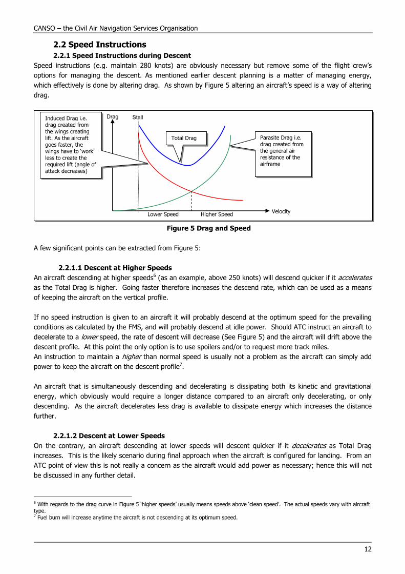
which effectively is done by altering drag. As shown by Figure 5 altering an aircraft’s speed is a way of altering
drag.
Figure 5 Drag and Speed
A few significant points can be extracted from Figure 5:
2.2.1.1 Descent at Higher Speeds
An aircraft descending at higher speeds6 (as an example, above 250 knots) will descend quicker if it accelerates
as the Total Drag is higher. Going faster therefore increases the descend rate, which can be used as a means
of keeping the aircraft on the vertical profile.
If no speed instruction is given to an aircraft it will probably descend at the optimum speed for the prevailing
conditions as calculated by the FMS, and will probably descend at idle power. Should ATC instruct an aircraft to
decelerate to a lower speed, the rate of descent will decrease (See Figure 5) and the aircraft will drift above the
descent profile. At this point the only option is to use spoilers and/or to request more track miles.
An instruction to maintain a higher than normal speed is usually not a problem as the aircraft can simply add
power to keep the aircraft on the descent profile7.
An aircraft that is simultaneously descending and decelerating is dissipating both its kinetic and gravitational
energy, which obviously would require a longer distance compared to an aircraft only decelerating, or only
descending. As the aircraft decelerates less drag is available to dissipate energy which increases the distance
further.
2.2.1.2 Descent at Lower Speeds
On the contrary, an aircraft descending at lower speeds will descent quicker if it decelerates as Total Drag
increases. This is the likely scenario during final approach when the aircraft is configured for landing. From an
ATC point of view this is not really a concern as the aircraft would add power as necessary; hence this will not
be discussed in any further detail.
6 With regards to the drag curve in Figure 5 ‘higher speeds’ usually means speeds above ‘clean speed’. The actual speeds vary with aircraft type. 7 Fuel burn will increase anytime the aircraft is not descending at its optimum speed.
Drag Stall
Total Drag Parasite Drag i.e. drag created from the general air resistance of the airframe
Induced Drag i.e. drag created from the wings creating lift. As the aircraft goes faster, the wings have to ‘work’ less to create the required lift (angle of attack decreases)
Velocity Lower Speed Higher Speed
Unstable Approaches – ATC Considerations
13
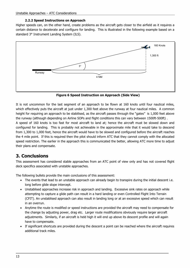
2.2.2 Speed Instructions on Approach
Higher speeds can, on the other hand, create problems as the aircraft gets closer to the airfield as it requires a
certain distance to decelerate and configure for landing. This is illustrated in the following example based on a
standard 3° Instrument Landing System (ILS).
Figure 6 Speed Instruction on Approach (Side View)
It is not uncommon for the last segment of an approach to be flown at 160 knots until four nautical miles,
which effectively puts the aircraft at just under 1,300 feet above the runway at four nautical miles. A common
height for requiring an approach to be stabilised, as the aircraft passes through the “gates” is 1,000 feet above
the runway (although depending on Airline SOPs and flight conditions this can vary between 1500ft-500ft) .
A speed of 160 knots is too fast for most aircraft to land at; hence the aircraft must be slowed down and
configured for landing. This is probably not achievable in the approximate mile that it would take to descend
from 1,300 to 1,000 feet, hence the aircraft would have to be slowed and configured before the aircraft reaches
the 4 mile point. If this is required then the pilot should inform ATC that they cannot comply with the allocated
speed restriction. The earlier in the approach this is communicated the better, allowing ATC more time to adjust
their plans and compensate.
3. Conclusions This assessment has considered stable approaches from an ATC point of view only and has not covered flight
deck specifics associated with unstable approaches.
The following bullets provide the main conclusions of this assessment:
• The events that lead to an unstable approach can already begin to transpire during the initial descent i.e.
long before glide slope intercept.
• Unstablised approaches increase risk in approach and landing. Excessive sink rates on approach while
attempting to capture a glide path can result in a hard landing or even Controlled Flight Into Terrain
(CFIT). An unstablised approach can also result in landing long or at an excessive speed which can result
in an overrun.
• Anytime the route is modified or speed instructions are provided the aircraft may need to compensate for
the change by adjusting power, drag etc. Larger route modifications obviously require larger aircraft
adjustments. Similarly, if an aircraft is held high it will end up above its descent profile and will again
have to compensate.
• If significant shortcuts are provided during the descent a point can be reached where the aircraft requires
additional track miles.
3°
4 NM
1,300 ft
160 Knots
Runway

CANSO – the Civil Air Navigation Services Organisation
14
• Rather than help the flight crew, reducing the remaining track distance can significantly increase the
flight-deck workload as the crew must attempt to catch the “new” descent profile while trying to maintain
a stabilised approach.
• An aircraft requires a significantly longer distance to simultaneously descend and decelerate compared to
just descending or decelerating.
• When providing aircraft with vectors for approach, early, regular and accurate track distance information
from the approach controller increases the crew’s ability to calculate an accurate achievable descent
profile and reduce the chances of an unstable approach occurring.
• A late runway change significantly increases crew workload and increases the potential for error, which
could result in an unstable approach. If the change results in a shorter route compared to the original
route more track miles could be required.
• Flight crew usually find non-precision approaches more complex as they include more elements and are
not performed as often as precision approaches. Speed instructions to aircraft that are inside the FAF are
not recommended. Due to the associated increase in cockpit workload the aircraft should be vectored for
longer finals, for a non-precision approach, than for a precision approach.
• Visual approaches and circling approaches are more error prone than full instrument approaches; if ATC
do not offer these types of approaches the pilots will probably execute the approach that they have
briefed and are prepared for, thus reducing the risk of an unstable approach occurring.
• Instructing an aircraft to reduce speed during the upper parts of the descent will usually cause it to drift
above its descent profile.
• Instructing an aircraft to maintain a higher than normal speed during the upper parts of the descent will
generally not result in problems with regards to maintaining the descent profile as power can be added.
• Requesting that an aircraft maintain a certain speed during final approach may conflict with the
requirements for a stable approach.
• Controllers should be aware that the FMS and ILS equipment is designed so that the localiser is captured
first then the glide-slope. If the glide-slope is captured before the localiser the aircraft may not be able to
continue the approach without it becoming unstable and the associated risk of CFIT increases.
• It is better for pilots and ATC to acknowledge that the approach is unstable and throw the approach
away early, rather than fight it on the way down anticipating that they will have the approach stabilised
by the minima e.g. 1000/500ft, only to go around at the stabilised approach point, or worse, continue to
land.
• Controllers should be wary of offering what they might consider to be as favourable alternatives e.g.
cutting the a/c in early, offering the option of a visual approach etc. This may lead the flight crew into
accepting an option that puts them into a situation where there is a significantly increased risk of the
flight/ approach becoming unstable.
Unstable Approaches – ATC Considerations
15
Appendix A Criteria for a Stable Approach
Although flying a stabilised approach is mandatory (EC Law) the actual criteria for a stable approach are not
mandated by law, but are instead established by each airline to suit their operations and then included in the
Airline’s Operations Manual. Therefore the criteria for continuing an approach tend to vary.
The following criteria are those defined by Flight Safety Foundation (Reference 2) and have been included for
illustration purposes only. Although these criteria should be viewed as ‘ballpark’ figures, most criteria used by
the airlines tend to be reasonably close to these:
• The aircraft must be on the correct flight path (ILS: within 1 dot GS/LOC; Visual approach: wings level at
500ft radio; Circling approach: wings level at 300ft);
• Only small heading and pitch changes required to maintain path;
• Speed must not deviate more than VRef+20kts/-0kts;
• The aircraft to be in proper landing configuration;
• A sink rate of max 1000 fpm (unless briefed otherwise);
• A power setting appropriate for aircraft configuration and not below the minimum power for an approach
as defined in the Aircraft Operations Manual;
• All briefings and checklists must be complete.
The above criteria tend to be applied at the following altitudes:
• IMC stable by 1000ft IMC;
• VMC stable by 500ft VMC (The aircraft should aim to be stable by 1,000 ft even in VMC conditions. If the
crew fail to achieve this then the gate can be reset to 500 ft, but only if the crew anticipate that the
aircraft will be stable by 500 ft, if not a missed approach has to be carried out). Note: The altitude at
which the gates are set and by which the approach is judged to be stable, varies depending on airline
SOPs and can range from 1500ft-500ft
EC Law now states:
• Without Visual Ground Reference: It is recommended that stabilisation be achieved at the latest when
passing 1,000ft above runway threshold elevation. If ATC procedures require higher speeds and is
allowed in the OM, the above gate may not be met, in this case stabilisation should be achieved by 500ft.
• With Visual Ground Reference: Stabilisation should be achieved by 500ft (however it is still recommended
that pilots use the 1000ft gate as above).
If the above gates are not met pilots should consider initiating a go-around maneuver.
Additionally, note the use of the words “recommended” and “should”.
CANSO – the Civil Air Navigation Services Organisation
16
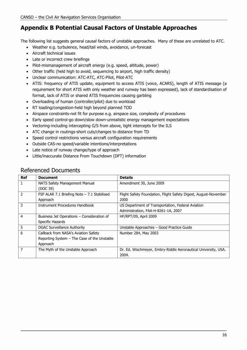
Appendix B Potential Causal Factors of Unstable Approaches
The following list suggests general causal factors of unstable approaches. Many of these are unrelated to ATC.
• Weather e.g. turbulence, head/tail winds, avoidance, un-forecast
• Aircraft technical issues
• Late or incorrect crew briefings
• Pilot-mismanagement of aircraft energy (e.g. speed, altitude, power)
• Other traffic (held high to avoid, sequencing to airport, high traffic density)
• Unclear communication: ATC-ATC, ATC-Pilot, Pilot-ATC
• ATIS: frequency of ATIS update, equipment to access ATIS (voice, ACARS), length of ATIS message (a
requirement for short ATIS with only weather and runway has been expressed), lack of standardisation of
format, lack of ATIS or shared ATIS frequencies causing garbling
• Overloading of human (controller/pilot) due to workload
• RT loading/congestion-held high beyond planned TOD
• Airspace constraints-not fit for purpose e.g. airspace size, complexity of procedures
• Early speed control-go down/slow down-unrealistic energy management expectations
• Vectoring-including intercepting G/S from above, tight intercepts for the ILS
• ATC change in routings-short cuts/changes to distance from TD
• Speed control restrictions versus aircraft configuration requirements
• Outside CAS-no speed/variable intentions/interpretations
• Late notice of runway change/type of approach
• Little/inaccurate Distance From Touchdown (DFT) information
Referenced Documents Ref Document Details
1 NATS Safety Management Manual
(DOC 39)
Amendment 30, June 2009
2 FSF ALAR 7.1 Briefing Note – 7.1 Stabilised
Approach
Flight Safety Foundation, Flight Safety Digest, August-November
2000
3 Instrument Procedures Handbook US Department of Transportation, Federal Aviation
Administration, FAA-H-8261-1A, 2007
4 Business Jet Operations – Consideration of
Specific Hazards
HF/RPT/09, April 2009
5 DGAC Surveillance Authority Unstable Approaches – Good Practice Guide
6 Callback from NASA’s Aviation Safety
Reporting System – The Case of the Unstable
Approach
Number 284, May 2003
7 The Myth of the Unstable Approach Dr. Ed. Wischmeyer, Embry-Riddle Aeronautical University, USA.
2004.

Unstable Approaches – ATC Considerations
17
Notes

CANSO – the Civil Air Navigation Services Organisation
18
Notes

Unstable Approaches – ATC Considerations
19
Notes

Aena – SpainAEROTHAI – ThailandAirports Authority of IndiaAirservices AustraliaAirways New ZealandANS of the Czech RepublicATNS – South AfricaBULATSA – BulgariaAustro Control – AustriaAvinor – NorwayANWS - TaiwanAZANS – AzerbaijanBelgocontrol – BelgiumCAA - UgandaCAAS – SingaporeCARC - JordanDECEA - BrazilDFS – GermanyDHMI – TurkeyDSNA – FranceEANS – EstoniaENAV SpA – ItalyFAA – USAFinavia Corporation – FinlandGACA – Kingdom of Saudi ArabiaGCAA – United Arab EmiratesHellenic Civil Aviation AuthorityHungaroControlIrish Aviation AuthorityISAVIA – IcelandKazaeronavigatsia – Kazakhstan
LFV – SwedenLGS – LatviaLPS Slovak RepublicLuxembourg ANALVNL – the NetherlandsMATS – MaltaNAATC – Netherlands AntillesNAMA - NigeriaNANSC – EgyptNATA - AlbaniaNATS – UKNAV CANADANAV PortugalNaviair – DenmarkOACA – TunisiaOro Navigacija – LithuaniaPANSA – PolandPristina International Airport J.S.C.ROMATSA – RomaniaSakaeronavigatsia Ltd – GeorgiaSENEAM - MexicoSercoskyguide – SwitzerlandSlovenia ControlSMATSA – SerbiaState ATM Corporation – RussiaUkSATSE – Ukraine
Full Members Associate MembersGold MembersAbu Dhabi Airports CompanyAirbusBoeing ATMEra CorporationFREQUENTIS AGGroupEAD Europe S.L.ITT CorporationLockheed MartinMetron AviationRaytheonSELEX Sistemi Integrati S.p.A.Sensis CorporationTelephonics Corporation, ESDThales
Silver MembersAbu Dhabi Department of TransportAdacel Inc.ARINCATC Global (UBM Information Ltd)ATC NetworkATCA – JapanAviation Advocacy SarlAvitech AGBarco N.V.Booz Allen HamiltonBrüel & Kjaer EMSComsoft GmbHDubai AirportsEADS CassidianEIZO Technologies GmbHEmiratesEntry Point North
Etihad AirwaysFokker Services B.V.GE Aviation’s PBN ServicesHarris CorporationHeliosHITT TrafficHoneywell International Inc./ AerospaceIDS – Ingegneria Dei Sistemi S.p.A.Indra SistemasIntegra A/SIntelcan Technosystems Inc.JeppesenL-3 Communications ESSCOLEMZ R&PLFV Aviation Consulting ABLochard EMSMicro Nav LtdThe MITRE Corporation – CAASDM.L.S. International CollegeNaverus, Inc.Nokia Siemens NetworksNorthrop Grumman– Park Air SystemsQuintiqSaab ABSITASELEX Systems Integration Inc.Ubitech Systems, Inc.U.S. DoD Policy Board on Federal AviationWIDE
Last updated 18 January 2011
Lighter areas represent airspace
covered by CANSO Members
Who We Are & What We Do
CANSO – The Civil Air Navigation Services Organisation– is the global voice of the companies that provide air traffic control, and represents the interests of Air Navigation Services Providers worldwide. CANSO members are responsible for supporting over 85% of world air traffic, and through our Workgroups, members share information and develop new policies, with the ultimate aim of improving air navigation services on the ground and in the air. CANSO also represents its members’ views in major regulatory and industry forums, including at ICAO, where we have official Observer status.
JOINING CANSOThe membership of CANSO is drawn from a wide range of ANSPs and companies involved with the delivery of air traffic services. Membership offers them the chance to network formally and informally, exchange best practice, and
contribute to CANSO Workgroups, delivering the standards and policies that will drive the future development of Air Navigation Services.
Full (ANSP) Membership is open to all ANSPs, regardless of whether or not they are autonomous of their government. Associate members can apply for either Gold or Silver status, which brings differing levels of access to CANSO Workgroups and event and advertising discounts. All members get a free listing in the CANSO Yearbook, and have access to the GlobalATM Net, an extranet that is the hub of CANSO’s activities, and home to an extensive member database.
For further information on joining CANSO, please visitwww.canso.org/joiningcanso.