calibrating dial indicators
TRANSCRIPT
UNITED STATES DEPARTMENT OF THE INTERIORBUREAU OF RECLAMATION
PROCEDURE FOR
CALIBRATING DIAL INDICATORS
USBR 1007-89
INTRODUCTION
This procedure is under the jurisdiction of the Geotechnical Services Branch, code D-3760, Research and Laboratory ServicesDivision, Denver Office, Denver, Colorado. The procedure is issued under the fixed designation USBR 1007. The number immediatelyfollowing the designation indicates the year of acceptance or the year of last revision.
1. Scope
1.1 This designation outlines the procedure for cali-brating dial indicators for laboratory and field applications.
1.2 Method A outlines the calibration procedure usingprecision gauge blocks; Method B outlines the calibrationprocedure using a micrometer fixture.
2. Applicable Documents
2.1 USBR Procedures:USBR 1000 Standards for Linear Measurement DevicesUSBR 3900 Standard Definitions of Terms and SymbolsRelating to Soil Mechanics
2.2 ASMEStandard:ANSI B89.1.10 Dial Indicators (for Linear Measurement)
2.3 Federal Specification:GGG-G-15C Gage Blocks and Accessories
3. Summary of Method
3.1 Comparison readings between a dial indicator andeither precision gauge blocks (method A) or a micrometerfixture (method B) are used to determine the accuracy,repeatability, and hysteresis of the dial indicator. The resultsare used to evaluate the acceptability of dial indicators forlaboratory and field use.
4. Significance and Use
4.1 Accurate linear measurements are required toobtain proper data for laboratory and field use.
4.2 Calibrate dial indicators when purchased andannually thereafter.
5. Terminology
5.1 Definitions are in accordance with USBR 3900.5.2 Terms not included in USBR 3900 specific to this
designation are:5.2.1 Accuracy.-The degree to which displayed dial
indicator readings vary from known spindle displacements.5.2.2 Graduation.-The least measured value which
is marked on the dial indicator face.5.2.3 Hysceresis.-The difference in displayed dial
indicator readings at any particular spindle displacement
within the specified range, when the dial indicator readingis approached first with increasing and then with decreasingspindle displacements.
5.2.4 Range.-The measured values over which thedial indicator is intended to measure, specified by upperand lower limits.
5.2.5 Repeatabil#y.-The degree to which displayeddial indicator readings vary for successive measurementsof the same reference.
6. Apparatus
6.1 Dial Indicator.-A dial indicator used for standardlaboratory or field applications.
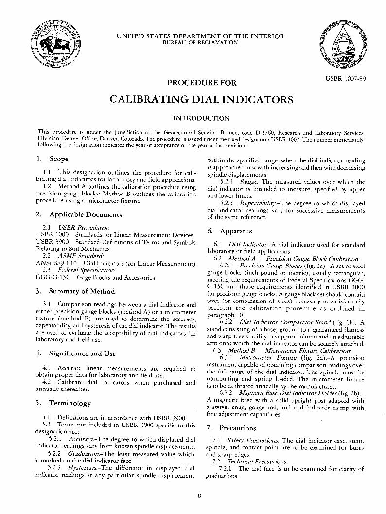
6.2 Method A --Precision Gauge Block Calibration:6.2.1 Precision Gauge Blocks (fig. la).-A set of steel
gauge blocks (inch-pound or metric), usually rectangular,meeting the requirements of Federal Specifications GGG-G-15C and those requirements identified in USBR 1000for precision gauge blocks. A gauge block set should containsizes (or combination of sizes) necessary to satisfactorilyperform the "calibration procedure as outlined inparagraph 10.
6.2.2 Dial Indicator Comparator Stand (fig. lb).-Astand consisting of a base; ground to a guaranteed flatnessand warp-free stability; a support column and an adjustablearm onto which the dial indicator can be securely attached.
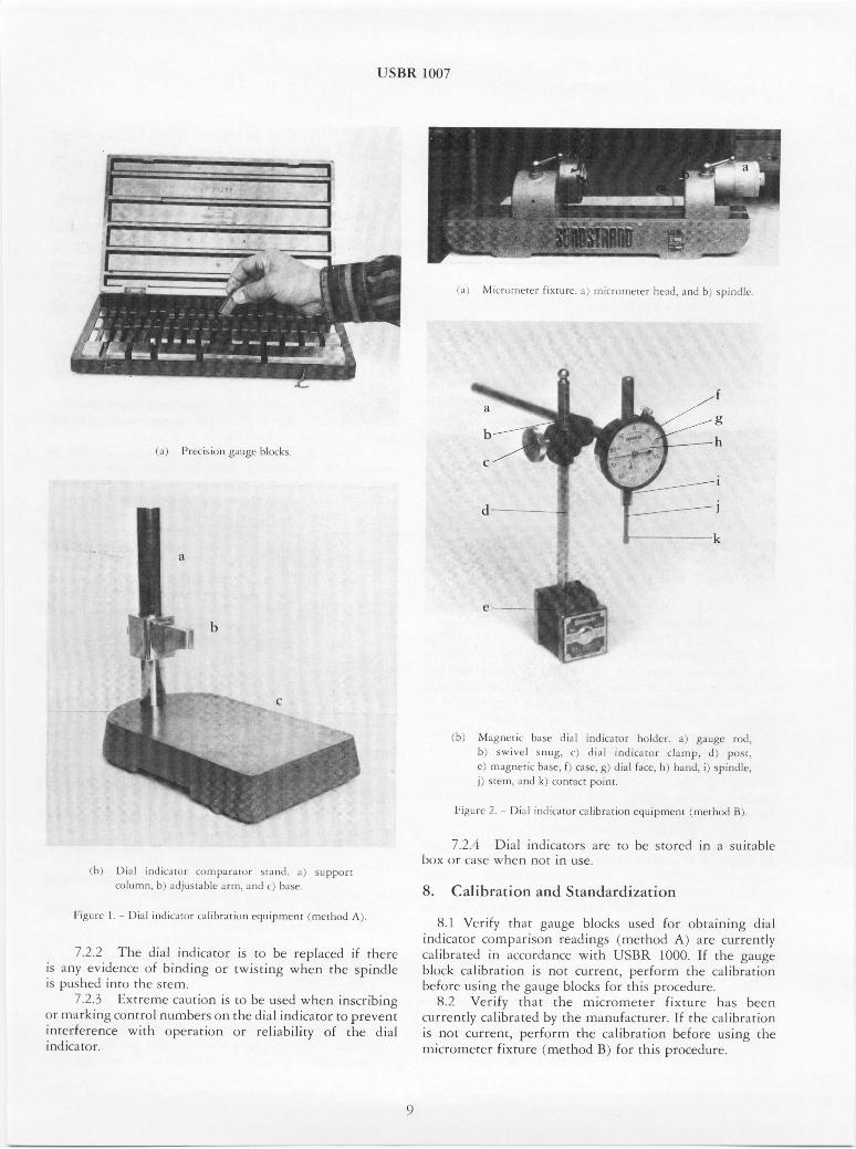
6.3 Method B- Micrometer Fixture Calibration:6.3.1 Micrometer Fixture (fig. 2a).-A precision
instrument capable of obtaining comparison readings overthe full range of the dial indicator. The spindle must benonrotating and spring loaded. The micrometer fixtureis to be calibrated annually by the manufacturer.
6.3.2 Magnetic Base DialIndicatorHolder ( fig. 2b).-A magnetic base with a solid upright post adapted witha swivel snug, gauge rod, and dial indicat& clamp with.fine adjustment capabilities.
7. Precautions
7.1 Safety Precautions.-The dial indicator case, stem,spindle, and contact point are to be examined for burrsand sharp edges.
7.2 Technical Precautions:7.2.1 The dial face is to be examined for clarity of
graduations.
USBR bil)(:l,7
!•1; I,: I; It Itl };:•11 D•.. h' Jl:i,; 1, ':Ill :,k i" L J,! •r]c ]l k[',l I,I!,
i,] : J:'r¢ ,: il•ii,ll •LILIL,' ' ]IlIl( •;:q.
,k•, [>Ld !l,li,;;:l,:.: •;,n:l:•q.t:,,i ,.1•111,! •, .<qr, l:,,z]
l<:,: tttl]a, I:, : i;IiL !;l;i;7>il • ;T It h .] lid ,i I:, t•U
]:imm: I I:],i;•l m,]it;•,, ,:;Lhitr:,rzm,=,•J <,:i!,•il-,m,L'lll , m,e.d>:•.J ,:,,;
722 Th,•: ,:t!i;i,l iY,,.diiazm•¢ is •,:, bc repl•JceJ i:•: tlxcl.•i'• ;•,In:y e'<'J.•lem:,•ce •:,t bhn,lin•: ,:,•: u&rJihl'Li•alg ',vlles• dJe spmJll,:i5 t'=,Ll'-,lIel:l Jilnt<:, []:I,L: 5 I:£1VI
7 • !!:l E:•at•t!lll•t thl,;Itjl•i,l:] iS •,le II';•(!l 'wt-,en irJs,Crit:::li:ll•.,;
< :i ii i i ] k il 1,- 1'• Ji ['1 • (i ( :l •21/. r" I Ii I :1 ] I I • 71 ] •l I •: •7 &l II ]1 In • t-ll e ,.!l ] k t ]! i Jl • < :l i C •J 1:. c:i [" [[ (> j-:l 1" •. ', ( ]: ] [
il:l[t!•lerc'nce ',!,•[¢hl •lll::,eral-i,:>•l ,:•r l:eli•q:,i]lity ,W: d-•e d, ia:li i l•:l ica•c •,1
e .....
]'<1 •,.:•<li, I:,•>h •!,;: Jl,ll:¢.ll.;,* I;,=ILI¢,• •; E!,;IIIL!:L [I,LI.•>: :•'"il.,tl HIIL;•, L: Ji;ll i;:;Ji,.•t,:,l '[ ];l[]:l;il ` iI:, :1i,;.>17.
:i i >,I:U[I] •i IlL{ 1,:1 I I}[][;1<'{ •!1 I[1:11
F[•u,c :l:,.i;,I i]hli, LIE,]IF ,:;lllilliI;tlli,:.ll {'l:•t;illiIIIJ(q]l I" I: K j•:
7.•!.]; [)i;I] il]lL•L:iLk][l:)•'S il[t•! £1:1 L]'L. <;l•':•'C':•[ ,in • Stl.i•l::,le'
17,,l:,:k: (iF LZI•;C ',•,. IJl£1:l I]';)[ i•]l l.:lq•
8. CaJ[ibrr, tion and S•arMardiizatu:)n
8.1 •'•..2c l :i f). I £11•l;],t •i;•lLll.ge: bllli(ks tll•.;u<:l l(/r ii:)I-:l,[[•l[•i:]l]g; dii;LI
Ji[],:]iC•lt,;J,l" ICll ['[]']•]1;]] ]S'[IIn •" e:]d [ •}gl;•;I (rll*UrLIlu(:,,:l k ) alKe .:lLirrel!•( ]3';
£ a I R ii D) F a E L' L'k i rll ; 1 'L 'C ,I ) y J: t* [ i C e V..' i *] ] 1:_ : S •;i • I '[L)O I:: }. ] t "[ I1-• C •.!;•/LII .y C
•::} ] I: }el{: C• ] 1•:I•" •1 [ 1( :l•:l i El [-Jll;:]l[ k.:L]I'•7£Jl[, ].]l('lt(}l:l]] [})C cz,:li•z:,r:•ii•:.zq
bef<,.te •.l>:ih-,g; :he gatJg;e k)[(]lCl.:s, fi: }] •hi> pr<,.,x.d urcS.2: X,TC•I;ii:}' t}']:•g [t'le' ]I]]J:c•;<:I'I'II,LttJ[" •i:i.:lL:lI'O h•l>; }7:1ec•1
,:ltlrrenl:l:}. cail ibr:•teJI b!.' d-• II]]LlI]Lt]:ACll"LilE(r • til-•e c•llil:l•;,{i<;,•]li"; •:*CIIt CLIYZTee'r]lL!, Fl'Q'I-fIIk)['•:]']l the ca•llibr•ci,:an bcf,,:•.•'c LIIhiJr],• I •tll]•.:
]lliCrc, me•e:t: f:i:,¢ftl•re If: Fr:let[],:3,cI BI ) fl: }:1" t l,i>; j•",I'(jlIIC:,eCt!L]F(:
USBR 1007
9. Conditioning
9.1 Perform this calibration in an environment as closeto 68 °F (20 °C) as possible.
9.2 The dial indicator, calibration gauge blocks, anddial indicator comparator stand and base should be in theenvironment in which they are to be calibrated for at least24 hours prior to calibration.
10. Procedure
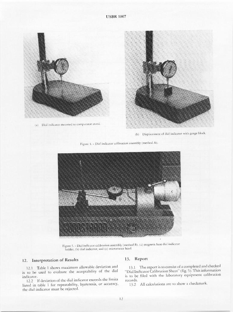
10.1 All data are to be recorded on the "Dial IndicatorCalibration Sheet" as shown on figure 3.
10.2 Record the range and graduation of the dialindicator to be calibrated.
10.3 Locate and record the manufacturer and serialnumber of the dial indicator to be calibrated. If it has noserial number, record the model number and any identifyingmarking.
10.4 Record the type and serial number of the referencestandard to be used.
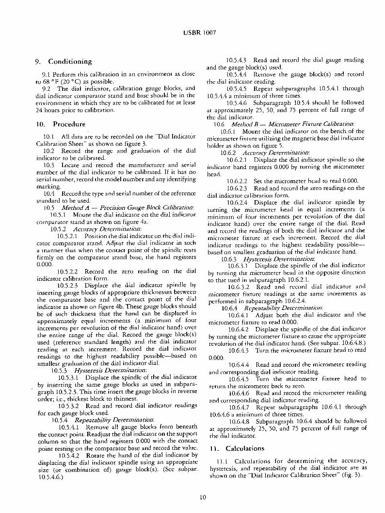
10.5 Method A -- Precision Gauge Block Calibration:10.5.1 Mount the dial indicator on the dial indicator
comparator stand as shown on figure 4a.10.5.2 Accuracy Determination:
10.5.2.1 Position the dial indicator on the dial indi-cator comparator stand. Adjust the dial indicator in sucha manner that when the contact point of the spindle restsfirmly on the comparator stand base, the hand registers0.000.
10.5.2.2 Record the zero reading on the dialindicator calibration form.
10.5.2.3 Displace the dial indicator spindle byinserting gauge blocks of appropriate thicknesses betweenthe comparator base and the contact point of the dialindicator as shown on figure 4b. These gauge blocks shouldbe of such thickness that the hand can be displaced inapproximately equal increments (a minimum of fourincrements per revolution of the dial indicator hand) overthe entire range of the dial. Record the gauge block(s)used (reference standard length) and the dial indicatorreading at each increment. Record the dial indicatorreadings to the highest readability possible--based onsmallest graduation of the dial indicator dial.
10.5.3 Hysteresis Determination:10.5.3.1 Displace the spindle of the dial indicator
by inserting the same gauge blocks as used in subpara-graph 10.5.2.3. This time insert the gauge blocks in reverseorder; i.e., thickest block to thinnest.
10.5.3.2 Read and record dial indicator readingsfor each gauge block used.
10.5.4 Repeatabffity Determination:10.5.4.1 Remove all gauge blocks from beneath
the contact point. Readjust the dial indicator on the supportcolumn so that the hand registers 0.000 with the contactpoint resting on the comparator base and record the value.
10.5.4.2 Rotate the hand of the dial indicator bydisplacing the dial indicator spindle using an appropriatesize (or combination of) gauge block(s). (See subpar.10.5.4.6.)
10.5.4.3 Read and record the dial gauge readingand the gauge block(s) used.
10.5.4.4 Remove the gauge block(s) and recordthe dial indicator reading.
10.5.4.5 Repeat subparagraphs 10.5.4.1 through10.5.4.4 a minimum of three times.
10.5.4.6 Subparagraph 10.5.4 should be followedat approximately 25, 50, and 75 percent of full range ofthe dial indicator.
10.6 Method B- Micrometer Fixture Calibration:10.6.1 Mount the dial indicator on the bench of the
micrometer fixture utilizing the magnetic base dial indicatorholder as shown on figure 5.
10.6.2 Accuracy Determination:10.6.2.1 Displace the dial indicator spindle so the
indicator hand registers 0.000 by turning the micrometerhead.
10.6.2.2 Set the micrometer head to read 0.000.10.6.2.3 Read and record the zero readings on the
dial indicator calibration form.10.6.2.4 Displace the dial indicator spindle by
turning the micrometer head in equal increments (aminimum of four increments per revolution of the dialindicator hand) over the entire range of the dial. Readand record the readings of both the dial indicator and themicrometer fixture at each increment. Record the dialindicator readings to the highest readability possible--based on smallest graduation of the dial indicator hand.
10.6.3 Hysteresis Determination:10.6.3.1 Displace the spindle of the dial indicator
by turning the micrometer head in the opposite directionto that used in subparagraph 10.6.2.1.
10.6.3.2 Read and record dial indicator andmicrometer fixture readings at the same increments asperformed in subparagraph 10.6.2.4.
10.6.4 Repeatability Determination:10.6.4.1 Adjust both the dial indicator and the
micrometer fixture to read 0.000.10.6.4.2 Displace the spindle of the dial indicator
by turning the micrometer fixture to cause the appropriaterevolution of the dial indicator hand. (See subpar. 10.6.4.8.)
10.6.4.3 Turn the micrometer fixture head to read0.000.
10.6.4.4 Read and record the micrometer readingand corresponding dial indicator reading.
10.6.4.5 Turn the micrometer fixture head toreturn the micrometer back to zero.
10.6.4.6 Read and record the micrometer readingand corresponding dial indicator reading.
10.6.4.7 Repeat subparagraphs 10.6.4.1 through10.6.4.6 a minimum of three times.
10.6.4.8 Subparagraph 10.6.4 should be followedat approximately 25, 50, and 75 percent of full range ofthe dial indicator.
11. Calculations
11.1 Calculations for determining the accuracy,hysteresis, and repeatability of the dial indicator are asshown on the "Dial Indicator Calibration Sheet" (fig. 3).
10

USBR 1007
7-2349 (5.86)Bureau of Reclamation DIAL INDICATOR CALIBRATIONSHEET Desiinat|onUSBR 1007---8_•
DIAL INDICATOR RANGE/GRADUATIONS
MANUFACTURER Example
REFERENCE STANDARD USED:.
CALIBRATION PERFORMED BY
CALIBRATION CHECKED BY
0-1.000 inch / 0.001 inch
[] GAUGE BLOCKSI• MICROMETER FIXTURE
SERIAL NO
SERIAL NO
SERIAL NO.
DATE
DATE
D1-115281
M F- I00
ACCURACY HYSTER EElS R EPEATABILITY
TRIAL REFERENCENO. STANDARD
LENGTH
(1) (2)
I 0. 000
2 0. 025
3 .0;050
4 0. 075
5 O. lO0
6 O. 125
7 O. 150
8 •0. 175
9 0.200
DIAL DIFFER- TRIAL REFERENCE DIALINDICATOR ENCE NO. STANDARD INDICATORREADINGS (2) - (3) LENGTH READING
(3) (4) (5) (6) (7)
0.000 0.000 89 .0.000 0.000
0.025 0.000 88 0.025 0.024
o.o56 o.-ooo- 87 0.o5o 0.0500.075 0.000 86 0.075 0.074
0.100 0.000 85 0.100 0.100
0.125 "0.000 84 0;125 0.125
0.150 0.000 83 0.150 0.150
0.175 0.000 82 0.175 0.175
0.200 0.000 81 0.200 0.199
HYSTER-ESIS
(3) - (7)
(8)
O. 000
O.001
0.000
O.001
0.000
0.000
0.000
0.000
0.001
BASEDIAL
READING
(9)
RETRACTED RETURN REPEAT-READING READING ASILITY
(to) (11) (g)- (tl)
I 12 REV{)LUT I ON
0.050 0.000 0.000
0.050 0.ooo o.ooo0.050 0.000 0.000
0.000
0.000
0.000
2 I/2 REVC _UTIONS---
0.000 0.250 0.000 0.000
0.000 0.250 0.000 0.000
0.000 0.250 0.000 0.O00
ACCURACY: ACCEPT []
REJECT []
HYSTERESIS: ACCEPT []
REJECT []
REPEATABILITY: ACCEPT []
REJECT []
REMARKS: Only partial calibration data shown.
Figure 3. - Dial indicator calibration sheet --example.
GDO 850-947
ll
USBR ]LC•07
}x:i,z•;,,re •, l'J'i;LI hklic:m :,• i. allil[)l•;Iti '•I1 :l•;SeIllJZ:'[Ji!f' I -,L: I,:•d I!I,L ,: ,, n', •+•:•,,:':i,• I,,US•. ,::ILuL in,Jicah:,l
!1 •,L•Lde•, • I•, [: ,:thtl i• J,•l i,• ;•I,: :,u, :• •i •,L!: ': ,• :' m ice,: :,,I JeEe• I • •s,d
1L2.. lnter'pre•atio.r• o,f Re.su]l.ts
li2.1J Table I s]>,.',vs m•u:,i,num a]lL•,,wable ,J.eviad,:m •mdis t.,::, k>e tl.,iud tc,, e•,altlla•e El++c >LC<%tT>t+•bJlJc:•' ':•'•: the ,J[=•li n<;I ic4 ,:<:,,•
/. 2.2: If: dc:vii•i,::,n ,;>f {}q,,c dlia] iJ-tuLic•++c:,.r e>+ceedls d-:,e limit>i,liisted ilq, tab]ie l t+,:.J• " rcpeal+.Lbi]ity> tr•ys•e':esis+ or •,++,,.:L'xrac?',.tl'll,e Cli;]] i!l'J'L]jiIl::k:e*II:)m" •]-JIL]S,•+ be rei, e•e'd
13. Repo• '+•
] -', !1 The •ep,:>rt it> t,•l. c<:,,r•>.ist ,i,f •t c< :,.t•qT>h,::tc'd an.l ct:•ecked
is :•:, be •fiilec[ v,,id,+• d,+•e l:l/-*<:,t•,:w'S: equiF:'l•:,ent calil_-:,.rzLti•:,n1 CC'• I,• ,d s.
] !•."i kl]l C;1]Ct]l]+t/Ljl:)l]{; dil;€ {<1, ?,lji;)',x.r ;+ll c{llc'c'i<lqil;ll:k.
12

USBR 1007
Table 1. - Dial indicator maximum deviation.
AccuracySmallest Repeatability Hysteresis First 2-1/3 First 10graduation revolutions revolutionsinch mm
First 20*revolutions
Deviation in unitsofsmallestgraduation
0.00005 0.00l +0.2 0.50 __l _____4.00010 .002 +0.2 .50 ±1 ±3 _____4.00050 .010 ___+0.2 -33 __--+1 ---+3 ---4.00100 .020 ---0.2 .33 ,,,1 _____2 ---4
* Over 20 revolutions consult with individual manufacturers for standard procedure.Table 1 taken from ANSI B 89.1.10-1978 dial indicators for linear measurements.
13