calgary international airport tenant … international airport tenant design standards &...
TRANSCRIPT
CALGARY INTERNATIONAL AIRPORT
TENANT DESIGN STANDARDS & GUIDELINES
April 2009
Calgary International Airport Tenant Design Standards & Guidelines
April 2009 Page 1 of 4
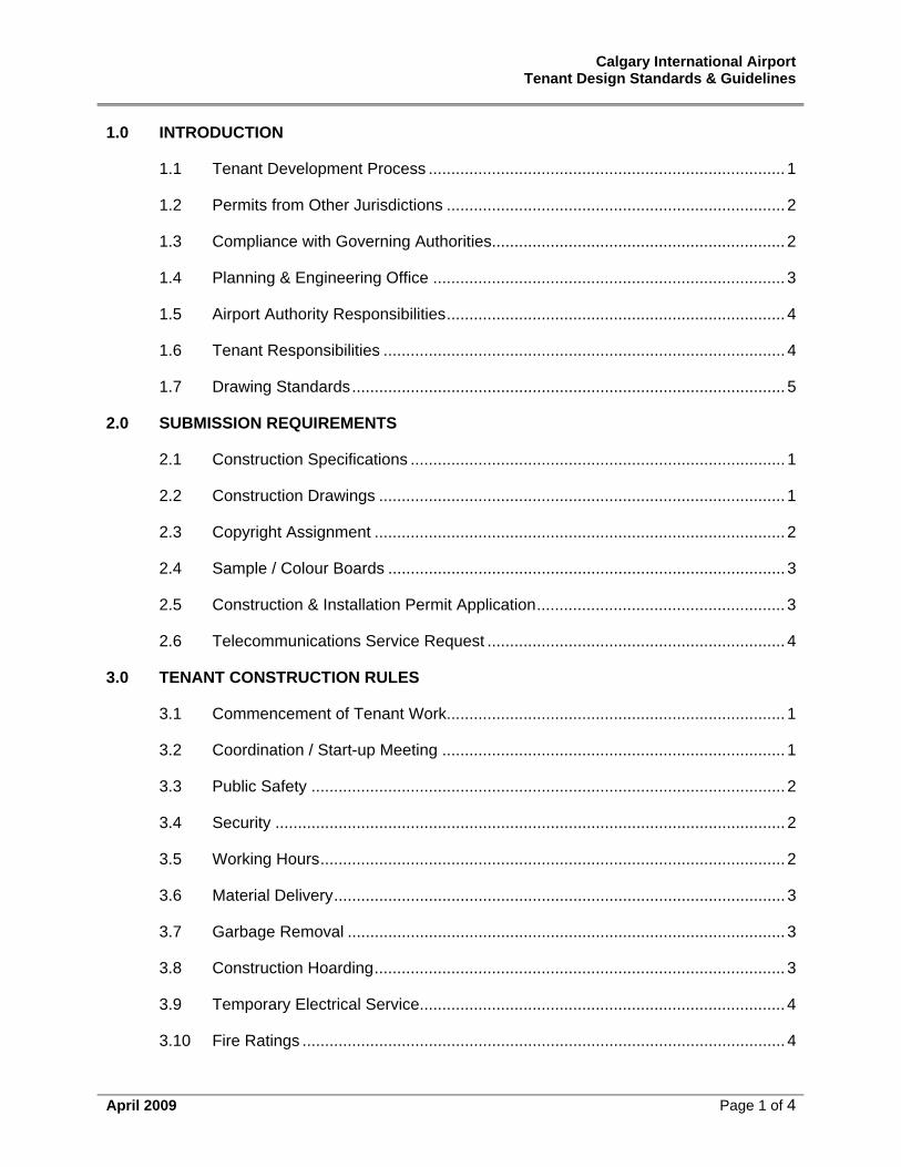
1.0 INTRODUCTION
1.1 Tenant Development Process ............................................................................... 1
1.2 Permits from Other Jurisdictions ........................................................................... 2
1.3 Compliance with Governing Authorities................................................................. 2
1.4 Planning & Engineering Office .............................................................................. 3
1.5 Airport Authority Responsibilities........................................................................... 4
1.6 Tenant Responsibilities ......................................................................................... 4
1.7 Drawing Standards................................................................................................ 5
2.0 SUBMISSION REQUIREMENTS
2.1 Construction Specifications ................................................................................... 1
2.2 Construction Drawings .......................................................................................... 1
2.3 Copyright Assignment ........................................................................................... 2
2.4 Sample / Colour Boards ........................................................................................ 3
2.5 Construction & Installation Permit Application....................................................... 3
2.6 Telecommunications Service Request .................................................................. 4
3.0 TENANT CONSTRUCTION RULES
3.1 Commencement of Tenant Work........................................................................... 1
3.2 Coordination / Start-up Meeting ............................................................................ 1
3.3 Public Safety ......................................................................................................... 2
3.4 Security ................................................................................................................. 2
3.5 Working Hours....................................................................................................... 2
3.6 Material Delivery.................................................................................................... 3
3.7 Garbage Removal ................................................................................................. 3
3.8 Construction Hoarding........................................................................................... 3
3.9 Temporary Electrical Service................................................................................. 4
3.10 Fire Ratings ........................................................................................................... 4
Calgary International Airport Tenant Design Standards & Guidelines
April 2009 Page 2 of 4
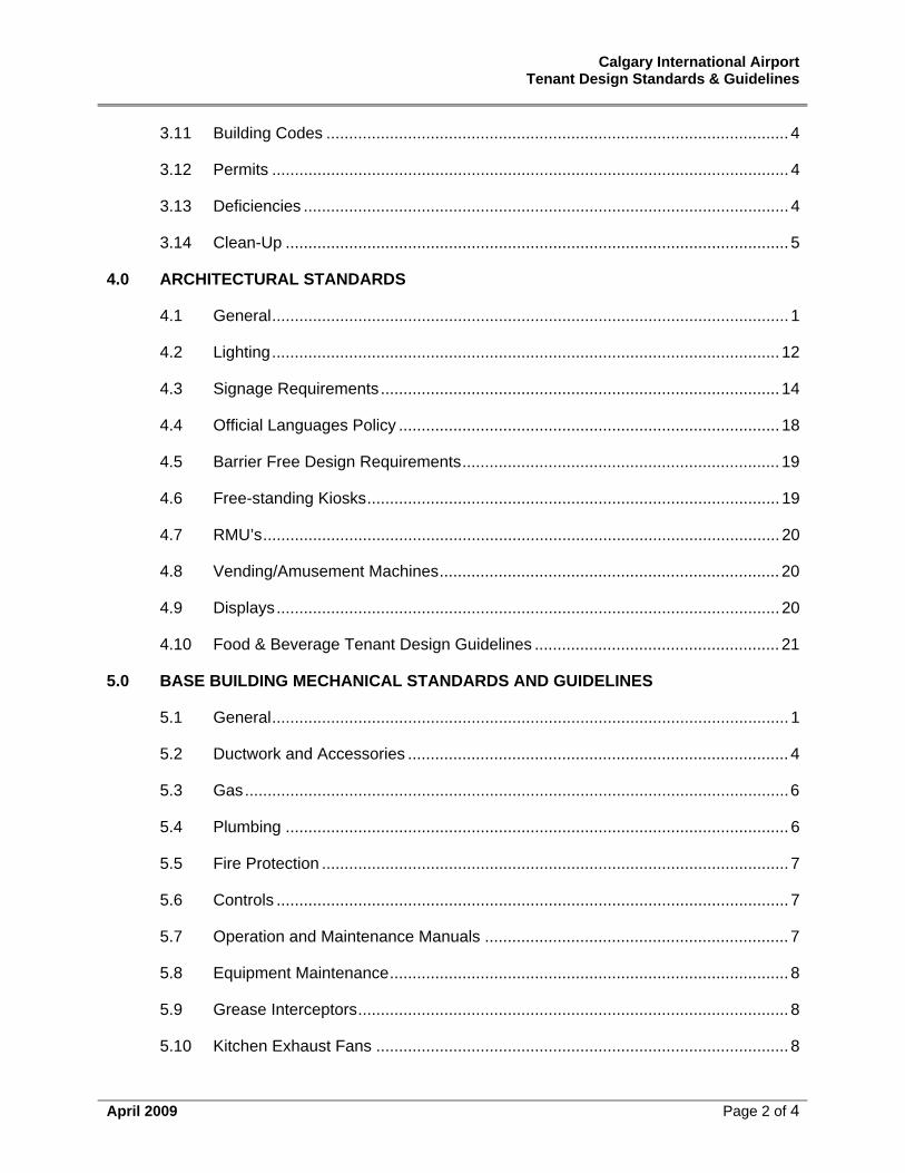
3.11 Building Codes ...................................................................................................... 4
3.12 Permits .................................................................................................................. 4
3.13 Deficiencies ........................................................................................................... 4
3.14 Clean-Up ............................................................................................................... 5
4.0 ARCHITECTURAL STANDARDS
4.1 General.................................................................................................................. 1
4.2 Lighting................................................................................................................ 12
4.3 Signage Requirements........................................................................................ 14
4.4 Official Languages Policy .................................................................................... 18
4.5 Barrier Free Design Requirements...................................................................... 19
4.6 Free-standing Kiosks........................................................................................... 19
4.7 RMU’s.................................................................................................................. 20
4.8 Vending/Amusement Machines........................................................................... 20
4.9 Displays............................................................................................................... 20
4.10 Food & Beverage Tenant Design Guidelines ...................................................... 21
5.0 BASE BUILDING MECHANICAL STANDARDS AND GUIDELINES
5.1 General.................................................................................................................. 1
5.2 Ductwork and Accessories .................................................................................... 4
5.3 Gas........................................................................................................................6
5.4 Plumbing ............................................................................................................... 6
5.5 Fire Protection ....................................................................................................... 7
5.6 Controls ................................................................................................................. 7
5.7 Operation and Maintenance Manuals ................................................................... 7
5.8 Equipment Maintenance........................................................................................ 8
5.9 Grease Interceptors............................................................................................... 8
5.10 Kitchen Exhaust Fans ........................................................................................... 8
Calgary International Airport Tenant Design Standards & Guidelines
April 2009 Page 3 of 4
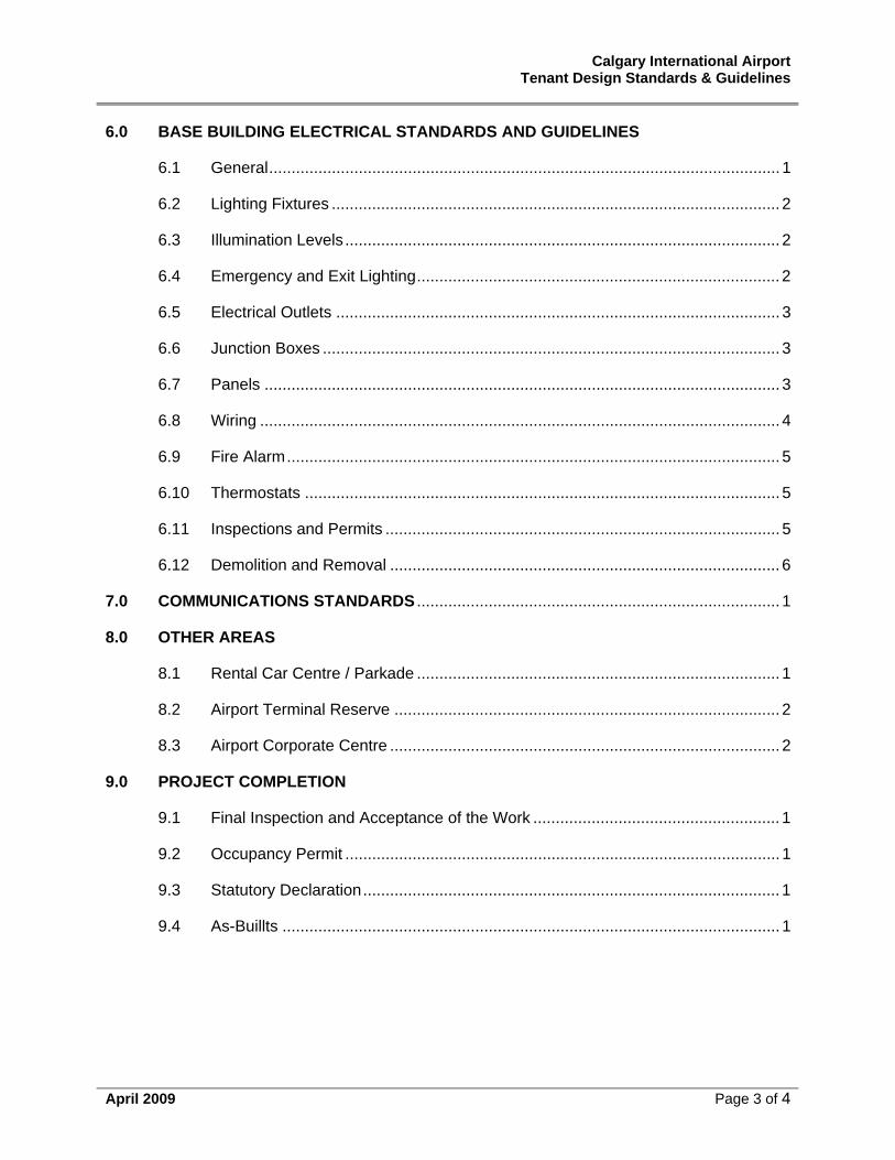
6.0 BASE BUILDING ELECTRICAL STANDARDS AND GUIDELINES
6.1 General.................................................................................................................. 1
6.2 Lighting Fixtures .................................................................................................... 2
6.3 Illumination Levels................................................................................................. 2
6.4 Emergency and Exit Lighting................................................................................. 2
6.5 Electrical Outlets ................................................................................................... 3
6.6 Junction Boxes ...................................................................................................... 3
6.7 Panels ................................................................................................................... 3
6.8 Wiring .................................................................................................................... 4
6.9 Fire Alarm.............................................................................................................. 5
6.10 Thermostats .......................................................................................................... 5
6.11 Inspections and Permits ........................................................................................ 5
6.12 Demolition and Removal ....................................................................................... 6
7.0 COMMUNICATIONS STANDARDS ................................................................................. 1
8.0 OTHER AREAS
8.1 Rental Car Centre / Parkade ................................................................................. 1
8.2 Airport Terminal Reserve ...................................................................................... 2
8.3 Airport Corporate Centre ....................................................................................... 2
9.0 PROJECT COMPLETION
9.1 Final Inspection and Acceptance of the Work ....................................................... 1
9.2 Occupancy Permit ................................................................................................. 1
9.3 Statutory Declaration............................................................................................. 1
9.4 As-Buillts ............................................................................................................... 1
Calgary International Airport Tenant Design Standards & Guidelines
April 2009 Page 4 of 4
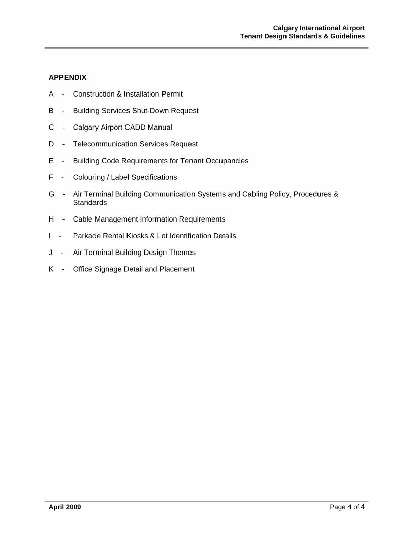
APPENDIX
A - Construction & Installation Permit
B - Building Services Shut-Down Request
C - Calgary Airport CADD Manual
D - Telecommunication Services Request
E - Building Code Requirements for Tenant Occupancies
F - Colouring / Label Specifications
G - Air Terminal Building Communication Systems and Cabling Policy, Procedures & Standards
H - Cable Management Information Requirements
I - Parkade Rental Kiosks & Lot Identification Details
J - Air Terminal Building Design Themes
K - Office Signage Detail and Placement
Calgary International Airport Tenant Design Standards & Guidelines
Definitions and Abbreviations
April 2009 Page 1 of 2
DEFINITIONS AND ABBREVIATIONS Air Terminal Building Complex
This represents the terminal building, parkade and rental car centre.
Airport Authority The Calgary Airport Authority
ATB Air Terminal Building
Base Building Drawing The Base Building Drawing is a drawing provided by the Landlord that documents all base building planning information pertaining to the Leased Premises. The information is provided in the form of a scaled drawing(s) identifying in plan, the location of all base building services provided by the Landlord, existing structural elements (if any) within the Leased Premises, demising wall and lease line locations. From this information the Tenant’s consultants develop their design and construction documents.
CIA Calgary International Airport
Construction Documents Drawings and specifications prepared by the Tenant’s consultants that allow the Tenant to obtain a building permit, tender a project and construct their premises.
Construction Installation Permit (CIP) A Construction Installation Permit (CIP) is a permit issued by the Calgary Airport Authority allowing the alteration of lands and/or buildings managed by the Airport Authority. The issuance of a CIP is the means by which the Airport Authority monitors changes and coordinates all affected parties. Each Tenant must obtain a Construction Installation Permit (CIP) from the Calgary Airport Authority prior to proceeding with any work.
Demising Wall The common wall between two adjacent Leased Premises or between a Leased Premise and a common area. The demising wall extends back from a neutral pier or demising cap.
Demising Cap Architectural element separating two adjacent Leased Premises or a Leased Premise and a service corridor.
Design Control Zone An area established by the Landlord inside the Tenant’s Leased Premises within which the Landlord maintains the right to approve all the Tenant’s materials, finishes, fixture layout, signage, fittings, display and lighting elements.
Calgary International Airport Tenant Design Standards & Guidelines
Definitions and Abbreviations
April 2009 Page 2 of 2
Development Coordinator Reference to the Airport Development Coordinator will be either the Manager, Development Services or the Development Coordinator.
Landlord Calgary Airport Authority is the Landlord of Calgary International Airport
Lease Line The line shown on the Base Building Drawing defining the confines of the tenant’s demised premises.
Leased Premises The area leased by the Landlord to the Tenant as defined in the Base Building Drawing and the Lease Agreement.
Material Controls The Landlord’s right to review and approve all materials specified for tenant spaces. Tenants are required to use finishes and materials that are compatible with the base building.
Storefront Front face of the Leased Premises. In the case of a premise with more than one exposure to the Concourse or public walkway, the storefront refers to all facades.
Tenant The legal name of the operator renting space from the Landlord
Tenant Detail Plans (TDP) The Tenant Detail Plans are the set of detailed design and construction documents prepared by the Tenant’s consultants and submitted by the Tenant as part of the CIP application and Building Permit. These must include all relevant plans, sections, elevations and detail drawings for the proposed project, including detailed engineering drawings.
YYC Calgary International Airport
Calgary International Airport Tenant Design Standards & Guidelines
Section 1 – Introduction
April 2009 Page 1 of 5
1.0 INTRODUCTION
The Air Terminal Building Tenant Design Standards and Guidelines is a manual prepared by the Airport Authority that outlines the technical and design requirements to assist the Airport Authority staff and consultants maintain the high level of workmanship, methods, materials, appearance and quality for any project undertaken in the Airport Terminal Building Complex. These are the minimum acceptable standards, and apply to all Tenant developments, alterations, improvements, and additions to the building and/or within the building.
In addition to outlining the design standards and guidelines, this document outlines the submission and approval process that all Tenants must follow. All projects must comply with these standards, unless authorized by The Calgary Airport Authority, Planning and Engineering Department.
The Calgary Airport Authority, as Landlord both in the Air Terminal Building and surrounding lands, has a responsibility, as set out in the Transport Canada Lease, to provide Transport Canada with information regarding any development. As a Tenant of The Calgary Airport Authority, the responsibility to comply with these standards is inherent. As such, the Airport Authority developed the Construction & Installation Permit to be used as a tracking tool and instrument to monitor tenant development and ensure that it meets the Airport Authority’s standards.
The Calgary Airport Authority reserves the right to amend these standards at any time. The Calgary Airport Authority also reserves the right to waive or increase these standards as may be required due to the specific characteristics and location of any given project. Should the Airport Authority refuse an application for development, the applicant will be provided with written reasons for refusal.
These Design Standards and Guidelines will apply to new and existing tenants upon any improvements or where applicable, lease renewals.
1.1 Tenant Development Process
A Construction & Installation Permit (CIP) application form (Appendix ‘A’) can be obtained from the Planning and Engineering offices of The Calgary Airport Authority or down loaded on line from the Calgary International Airport’s web site at www.yyc.com. The CIP application form must be filled out in its entirety and returned to the Planning and Engineering offices along with detailed drawings outlining the work that is to be performed. Base drawings can be requested from the Development Coordinator of The Calgary Airport Authority.
Once the application has been submitted and checked for completeness, a preliminary review will begin. The project will be circulated to those parties within the Airport Authority that may be affected. A review of all disciplines affected by the work will be detailed, and comments will be forwarded to the Tenant, or their authorized representative. Submissions may require revisions if it is incomplete, or does not meet the standards as laid out in this document.
Calgary International Airport Tenant Design Standards & Guidelines
Section 1 – Introduction
April 2009 Page 2 of 5
After revisions have been made to the satisfaction of the Airport Authority, a CIP may be issued to allow the tenant to begin work. It is important to note that other permits may be required from other authorities having jurisdiction (ie. The City of Calgary). In these instances a letter of authorization from the Airport Authority is required before a Tenant may apply for any such permits.
1.2 Permits from Other Jurisdictions
Once the Airport Authority has given its approval to the Tenant in the form of a letter of authorization, the Tenant may apply for a Building Permit from the City of Calgary. The City of Calgary will not accept or process a Building Permit application without a letter of authorization from the Airport Authority.
Once the Tenant has obtained a Building Permit from the City of Calgary, the Airport Authority will issue the CIP to the Tenant. Every Tenant must obtain a CIP from the Calgary Airport Authority prior to proceeding with any work.
1.3 Compliance with Governing Authorities
The following codes, regulations & acts shall apply as they relate to the specific development. Although this list attempts to be complete, it is the tenant’s consultants and contractor’s responsibility to ensure that all applicable codes and their most current regulations are adhered to, and that the appropriate permit(s) are displayed at the work site.
• Canadian Electrical Code and Alberta Appendices
• Canadian Environmental Protection Act
• Canadian Heating, Ventilating and Air Conditioning Code
• Canadian Labour Code - Part II
• Canadian Plumbing Code
• Canadian Occupational Safety and Health Regulations
• Alberta Building Code
• National Building Code
• National Fire Code
• Alberta Fire Code
• Alberta Environmental Protection and Enhancement Act
• Transportation of Dangerous Good Act (TDGA)
• Canadian Standards Association Barrier Free Design Manual; CAN/CSA B651-M90
Calgary International Airport Tenant Design Standards & Guidelines
Section 1 – Introduction
April 2009 Page 3 of 5
• CAN/CSA C22.2 214, Communication Cables
• CAN/CSA T527, Grounding and bonding for Telecommunications in Commercial Buildings
• CAN/CSA T529, Design Guidelines for Telecommunications in Commercial Buildings
• CAN/CSA T530, Building Facilities Design Guidelines for Telecommunications
• EIA/TIA 568A Building Telecommunications Cable Standards
• Alberta Occupational Health and Safety and its regulations
• Pressure Piping Code and Regulations, Boiler and Pressure Vessels Act., Government of Alberta
• American Society of Mechanical Engineers Code, Boiler and Pressure Vessels
• Workplace Hazardous Materials Information System (WHMIS)
• The Calgary Airport Authority, Calgary International Airport Air Terminal Building Tenant Standards and Guidelines
• The Calgary Airport Authority CADD Manual
In cases where more than one regulation applies to a specific situation, the most stringent requirement shall apply.
NOTE: the review of plans, specifications, and construction details, and the issuance of a Construction & Installation Permit by The Calgary Airport Authority, in no way relieves the tenant/owner and /or their consultants and contractors from complying with all applicable by laws, codes, regulations, and the most stringent requirements of all authorities having jurisdiction.
1.4 Planning & Engineering Office
The Tenant Development Coordinator represents the Landlord (The Calgary Airport Authority), and is the liaison between the Tenant and the Landlord for all review and approval phases from preliminary design to completion of construction.
Calgary International Airport Tenant Design Standards & Guidelines
Section 1 – Introduction
April 2009 Page 4 of 5
All correspondence, questions and submissions should be forwarded to:
The Calgary Airport Authority Calgary International Airport 2000 Airport Road N.E. Calgary, Alberta T2E 6W5 ATTENTION: Manager, Development Services [email protected] Fax: (403) 735-1283
1.5 Airport Authority Responsibilities
1.5.1 Base Building Drawings
The Airport Authority will provide the Tenant with base building drawings for the area being constructed. The tenant’s consultants must check and verify the accuracy of these drawings on site.
1.5.2 Submission Review
The CAA will review the submission within a reasonable time frame. CAA comments may be provided if changes are required to the design submission. If the CAA rejects a project submission, a written reason will be provided.
1.5.3 Coordination
The Development Coordinator will assist the Tenant with applications, permits, security escort coordination and other requests in order to ensure the project runs smoothly.
1.6 Tenant Responsibilities
1.6.1 Permit to Practice
It is the responsibility of the Tenant to hire qualified consultants and contractors, licensed to practice in the Province of Alberta.
1.6.2 Final Inspection
The Tenant must ensure that all consultants- architectural, electrical, mechanical and structural, (if applicable) who are responsible for the Tenant’s construction documents, perform a final inspection and ensure that the project has been constructed as per the construction documents and that all equipment and systems are operating as specified and designed. A copy of the final inspection report, list of equipment and acceptance of the work by the consultants must be forwarded to the
Calgary International Airport Tenant Design Standards & Guidelines
Section 1 – Introduction
April 2009 Page 5 of 5
Development Coordinator before the Airport Authority will accept the project as being complete.
1.6.3 Security
If the project takes place in a secure area, the Tenant is responsible for following Transport Canada regulations and providing or arranging for security escorts for the duration of the project.
1.6.4 Start-up Meeting
A pre-construction coordination / start-up meeting must be held prior to commencement of any work. See item (3.2).
1.6.5 Shutdowns
If service shutdowns within the project area are required during the construction period for any reason, the tenant or his authorized representative must make those arrangements. Forty-eight (48) hours notice will be required. The building services shutdown form is attached as Appendix ‘B’.
1.6.6 Final Inspection
1.6.7 As-built Drawings
It is a condition of the Tenant’s Lease Agreement that as-built drawings be submitted within 30 days of completion of the project. See item (9.4)
1.7 Drawing Standards
In general, all drawings are to be presented on a standard B1 size format. Information is to be metric and drawing text shall be a minimum of 2.5 millimeters in height and suitable for 1/2 size printing and scanning.
Facility base information is available in AutoCAD .dwg format and it is desirable to have Tenant submissions in the same format. Calgary Airport Authority CADD Standards are outlined in Appendix C.
Calgary International Airport Tenant Design Standards & Guidelines
Section 2 – Submission Requirements
April 2009 Page 1 of 4
2.0 SUBMISSION REQUIREMENTS
A complete submission will include a completed Construction & Installation Permit application form (Appendix ‘A’), and detailed drawings of the proposed project.
The Tenant must check actual site conditions, verify all job dimensions against the base building information provided by the Airport Authority’s Technical Data Centre and review all conditions of the Construction Schedule of the Lease Agreement, (if applicable) before proceeding with final construction drawings.
The Tenant must engage the services of licensed professionals in the design of architectural, mechanical and electrical drawings for construction and approval purposes. Drawings must bear the seal of a registered professional licensed to practice in the province of Alberta.
2.1 Construction Specifications
For all tenant projects, one hard copy of the Construction Specifications, utilizing the National Master Specification (NMS) format shall be submitted in MS Word 97 compatible format. Alternatively, a detailed outline, in written form, of the scope of work involved may be submitted.
2.2 Construction Drawings
Construction Drawings shall be submitted in the form of three (3) sets of black or blue line prints and one set of electronic files unless otherwise approved by the Planning and Engineering Department. Airport Authority CADD standards are provided (Appendix C) to ensure design firms using Airport Authority CADD drawings are able to understand the information but are not required adhere it is recommended for easier sharing of information.
In general, all drawings are to be presented on a standard B1 size format, information is to be metric and drawing text shall be a minimum of 2.5 millimetres and suitable for 1/2 size printing and scanning. All Drawings are to be scale drawings with dimensions, and are to include the following:
• key plan, showing location of project within the ATB (this key plan should be at a scale large enough to show required exits/access to exits, proximity to washrooms, etc.)
• detailed floor plans
• exterior and interior elevations
• sections and details, as required
• reflected ceiling plans, as required
• all signage, including type, materials, size, and location
Calgary International Airport Tenant Design Standards & Guidelines
Section 2 – Submission Requirements
April 2009 Page 2 of 4
• structural, mechanical, electrical, and telecommunication/data drawings as required, including details and performance characteristics of all equipment.
• Drawings shall show utility connection locations as well as the size of services. Where necessary, special systems or equipment drawings shall be submitted.
Standard Notes:
The following notes should appear on all drawings submitted for approval:
• “One set of Final Landlord Approved Drawings to be kept on site and available for checking at all times during construction.”
• “All materials to meet flame spread rating requirements of authorities having jurisdiction.”
• “All work to be scheduled through the Calgary Airport Planning Coordinator so that it does not interfere with Airport operations.”
In addition to the above, the drawings should indicate:
• Leasehold location, configuration, name and leasehold reference number on a key plan.
2.3 Copyright Assignment
Tenants designing facilities which are to be constructed on land sub-leased from the Calgary Airport Authority, or in buildings situated on Calgary Airport lands should be aware from the outset of discussions that the following paragraphs form part of the standard Lease Agreement. These paragraphs may have implications on the agreements that a Tenant will need to make with its consultants. The requirements set out below should be taken into account when entering into any design, design-build or consulting contract. These are obligations, which the Calgary Airport Authority is obliged to require of its Tenants under its Lease Agreement (Head Lease) with Transport Canada.
2.3.1 Prior to the commencement of construction of any Leasehold Improvement or installation of any utility, service or road, (collectively the “Project”), the Tenant shall provide and shall ensure that any Occupant provides the Landlord with satisfactory evidence that the Tenant or any Occupant, as the case may be, has obtained from the design, architectural and engineering consultants responsible for the preparation and creation of all design, construction and specification documents for the Project, an assignment and irrevocable non-exclusive license of the copyright of the design, construction and specification documents relating to the Project in favour of the Landlord and the Crown for the purpose of the Project only. Such assignment and license shall not include the right to use or duplicate any identifying logo, mark, trademark or industrial
Calgary International Airport Tenant Design Standards & Guidelines
Section 2 – Submission Requirements
April 2009 Page 3 of 4
design of the Tenant or of any Occupant or Transferee, nor shall such assignment and license grant any proprietary right whatsoever to the Landlord or to the Crown of any such identifying logo, mark, trademark or industrial design. The Agreement providing such assignment and license shall expressly state that neither the Landlord nor the Crown shall be responsible for any costs or expenses incurred or to be incurred in connection with the preparation of such design, construction and specification documents or their subsequent use by either the Landlord or the Crown, and that both the Landlord and the Crown are entitled to use the design, construction and specification documents for any purposes related to the Project whatsoever, at any time, without any further consent and without any further payment.
2.3.2 At the completion of the construction of the Project, the Tenant shall deliver to the Landlord, and shall ensure that any Occupant deliver to the Landlord, two (2) sets of reproducible “As Built” design, construction and specification documents with respect thereto, including copies of any electronic data embodying such documents and any program required for the use and interpretation of such data. The Landlord acknowledges that the design, construction and specification documents, the electronic data and program, as aforesaid, are valuable to the Tenant. The Landlord shall be entitled to use such design, construction and specification documents, electronic data and program only for such purposes as contemplated by this Lease or for any purpose relating to the Project after expiration or early termination of this Lease. The Landlord shall not disclose such documents, electronic data and program to any third party other than as is reasonably necessary for the purposes, as aforesaid; PROVIDED ALWAYS, that the Landlord shall be permitted to provide such documents, electronic data and program to the Crown in order that the Landlord may comply with its obligations in respect thereof under the Head Lease.
2.4 Sample / Colour Boards
Sample/Color Boards shall be submitted when required by the Planning & Engineering Department. Such boards shall include samples of proposed finish materials and colors, including but not limited to paint samples, floor and wall covering samples, plastic laminate samples, and illustrations of proposed lighting fixtures.
2.5 Construction & Installation Permit Application
A Construction & Installation Permit Application is attached as Appendix ‘A’. A digital copy of the file can be obtained by contacting the Development Coordinator. The form must be completed in its entirety.
Calgary International Airport Tenant Design Standards & Guidelines
Section 2 – Submission Requirements
April 2009 Page 4 of 4
2.6 Telecommunication Service Request (TSR)
The Telecommunication Service Request form (TSR) is provided by the Authority and TELUS to assist Airport Tenants in order their voice and data services at the airport.
This form must be used in all instances when requesting a change, addition, disconnection or removal of Telecommunication services within the Calgary Airport Property Boundary. These services include voice, data, video, Internet, telecommunications networks, or equipment. A copy of the TSR is attached as Appendix ‘D’.
Calgary International Airport Tenant Design Standards & Guidelines
Section 3 – Tenant Construction Regulations
April 2009 Page 1 of 5
3.0 TENANT CONSTRUCTION RULES
Based on the Landlord’s experience and in order to incur the least amount of inconvenience to all concerned, the following rules and requirements are applicable to all Tenants upon starting their construction work. These requirements will be enforced to ensure that there is no interruption to other businesses or public movement by Tenant contractor(s).
3.1 Commencement of Tenant Work
Unless otherwise expressly permitted or required by the Landlord, no Tenant Work may commence and the Tenant may not have possession of the Leased Premises until the following conditions have been satisfied:
• The Landlord has issued a Calgary Airport Authority Construction Installation Permit (CIP).
• The Landlord has approved the Tenant Design and the Tenant has submitted a construction schedule to the Landlord complete with 24-hour emergency contact list.
• All necessary approvals and permits of municipal and other governing authorities having jurisdiction over the Tenant’s work have been obtained.
• The Landlord has approved the Tenant’s contractors.
• The Landlord has notified the Tenant in writing of the date the Leased Premises are ready for the commencement of Tenant’s Work and upon which the Tenant is to take possession.
• The Lease Agreement has been fully executed.
• The Landlord has received a development security deposit from the tenant.
3.2 Coordination / Start–up Meeting
Prior to commencing work, a site meeting shall be arranged by the Development Coordinator and attended by a representative of the Tenant, the Tenant’s contractor, major subcontractors, the Tenant’s consultants and the Landlord.
Scheduling and coordination of all work shall be discussed including:
• all essential base building services to be maintained during construction.
• safety entry and egresses to be maintained.
• verification of construction schedule.
• verification of requirements for fire safety and construction safety to be maintained.
Calgary International Airport Tenant Design Standards & Guidelines
Section 3 – Tenant Construction Regulations
April 2009 Page 2 of 5
• noise and dust control with regard to normal building operations.
• verification of site access, storage areas and parking relative to the tenant’s contractor’s forces.
• scheduling of critical shut-downs and change-overs.
• Roles and responsibilities related to establishing emergency procedures.
3.3 Public Safety
It is the responsibility of the Tenant to ensure that its contractors exercise all caution in matters relating to construction and public safety and to comply with the Occupational, Health and Safety standards established by authorities having jurisdiction.
Where applicable, the Tenant shall designate a member of its’ contractors’ forces as the Prime Contractor responsible for work site safety for the project.
From time to time, the Landlord may issue to a Tenant’s contractor safety instructions, which must be strictly adhered to. All work is governed by the latest Construction Safety Act and the Tenant’s contractor must abide by the Landlord’s representative in these areas when required.
3.4 Security
Security of the Leased Premises during the construction and fixturing period is the sole responsibility of the Tenant. The Landlord assumes no liability for any loss or damage including the theft of building materials, equipment or supplies.
It will be necessary for all Tenants and construction personnel to comply with all applicable security legislation and regulations in effect at the Airport. Tenants and construction personnel shall adhere to security requirements such as:
• Airport Restricted Area Pass System Policy
• Airport Vehicle Operators Permit Policy
• Keys, Proximity Cards and Lock System Policy
• Airport Security Escorts (at the Tenant’s expense)
Documents and information related to the above regulations as well as other security related requirements are available from the Airport Pass Control Office.
3.5 Working Hours
The Tenant’s contractors and suppliers will be subject to restrictions, which may be imposed by the Landlord in regard to deliveries, hours of work, scheduling and co-ordination of work including, but not limited to night shifts and weekends.
Calgary International Airport Tenant Design Standards & Guidelines
Section 3 – Tenant Construction Regulations
April 2009 Page 3 of 5
It is the responsibility of the Tenant to coordinate with the Airport Development Coordinator the approved hours of work for their construction forces within the Airport Terminal Building.
Access to the Leased Premises for construction personnel and the delivery of material will be subject to restrictions imposed by the Landlord and the location of the Work.
Parking of vehicles by the Tenant’s workforce will be confined to those specific areas set aside for them. Contractor’s trailers are not permitted except by special permission of the Landlord.
3.6 Material Delivery
The Tenant and his contractor must coordinate the time, location, routing and method for all deliveries relating to the construction of the Leased Premises with the Airport Development Coordinator.
No construction material may be delivered through public areas without prior consent of the Landlord and no construction material may be stored or stockpiled in any public area.
3.7 Garbage Removal
The Tenant’s contractors will be required to remove all construction debris on a daily basis. The timing for garbage removal and the location of bins must be coordinated with the Airport Development Coordinator. In areas where the work is “airside”, measures must be taken to ensure that all garbage is enclosed and does not present a danger to airside operations (F.O.D.-Foreign Object Damage). Temporary storage of garbage or debris outside of the Leased Premises will not be permitted.
3.8 Construction Hoarding
Prior to commencing any work, the Tenant’s contractor should install a temporary hoarding in front of the Leased Premises. The hoarding should be of non-combustible metal stud and drywall construction sealed at the top and painted white with a 100mm high rubber or vinyl cove base to the Landlord’s approval.
The hoarding should be located a maximum of 900 mm (3'-0") in front of the Lease Line where possible and should be equal in height to the full premise opening (i.e. the space between the floor and the underside of the Landlord’s bulkhead). The top should be secured with polyethylene.
In order to protect the public concourse or walkway finish, plywood strips should be attached to the bottom of the hoarding. This will facilitate the moving of any hoarding if required during working hours. Hoarding should be securely braced into the Leased Premises behind the Lease Line. No mechanical fastening to the Base Building floor or structure will be permitted.
Calgary International Airport Tenant Design Standards & Guidelines
Section 3 – Tenant Construction Regulations
April 2009 Page 4 of 5
Where construction is being done in tandem with any base building or Landlord construction, the Landlord at the Tenant’s expense may undertake the erection of the Tenant’s hoarding.
Access to the Leased Premises for construction purposes should be from a rear corridor location or through a 900 x 2035 painted hollow metal door and frame complete with lockset. The Tenant shall provide the Airport Planning Coordinator with two sets of passkeys.
Hoarding must remain in place until authorization is received from the Airport Development Coordinator. If there are any major deficiencies found, the Tenant may be required to re-install the hoarding until deficiencies are corrected.
3.9 Temporary Electrical Service
The Landlord, through its contractor when active on site, may provide at the Tenant’s expense, temporary electrical service required during the Tenant’s construction phase.
3.10 Fire Ratings
During construction and / or demolition, care must be taken by the Tenant and its contractors to maintain existing fire walls, fire proofing and fire dampers in ductwork, notwithstanding any other work that may affect the fire rating requirements of authorities having jurisdiction. If the Tenant causes any damage to the fire rating, the Landlord will advise the Tenant to perform the necessary repairs or the Landlord will repair such damage at the Tenant’s expense.
3.11 Building Codes
It is the Tenant’s responsibility to fully comply with all applicable governing codes and ordinances for their occupancy type. Attached as Appendix ‘E’ are YYC/ATB Building Code Requirements for Tenant Occupancies.
3.12 Permits
The Tenant is responsible for obtaining at its own expense all approvals and / or permits pertaining to its space from all authorities having jurisdiction prior to commencement of construction.
All approvals and permits should be posted in a visible location.
3.13 Deficiencies
The Tenant should make good any deficiencies discovered by the Landlord or by the Building Inspectors whether in his own premises or in adjacent premises affected by the Tenant’s construction. Failure to comply with a written request within 30 days will cause the Landlord to correct tenant deficiencies at the Tenant’s expense.
Calgary International Airport Tenant Design Standards & Guidelines
Section 3 – Tenant Construction Regulations
April 2009 Page 5 of 5
3.14 Clean-Up
The Tenant should ensure proper clean up of all areas related to its work to the satisfaction of the Landlord prior to opening for business.

Calgary International Airport Tenant Design Standards and Guidelines
Section 4 – Architectural
April 2009 Page 1 of 25
42A
58A
82
44 39
49
54
59
64
69
74
79
8689
4.0 ARCHITECTURAL STANDARDS
The following architectural standards apply to all Tenants in the Air Terminal Building Complex.
4.1 General
All new development shall be sensitive to the original design of the Air Terminal Building, and will be required to maintain the building’s architectural integrity. All development shall recognize the fact that the building’s floor plan is not RECTANGULAR, but is RADIAL.
• Design consultants and contractors shall conduct a site inspection of the project area prior to the preparation of design drawings or concepts. A preliminary concept review may be conducted by the Airport Authority.
• The Air Terminal Building areas have been developed with a particular theming master plan (see Appendix J) and should be taken into account with all finishes and basic design. All proposed colours and materials shall be assessed against the theme colours and materials in order to determine compatibility.
• Prior to construction, design consultants and contractors shall contact the Development Coordinator to confirm the location of lease lines and all critical dimensions. All development must occur within the designated leased areas.
Calgary International Airport Tenant Design Standards and Guidelines
Section 4 – Architectural
April 2009 Page 2 of 25
• Where applicable, all proposals shall ensure that airside views are maintained and maximized.
• Any work undertaken in areas containing asbestos materials must comply with Alberta Occupational Health & Safety Standards.
• The Environmental Department shall be notified of any work that requires excavation.
• Use of combustible construction material in construction assemblies is expressly prohibited without prior approval of the Planning and Engineering Department.
4.1.1 Design Control Zone
The Landlord has established an area inside the Leased Premises called the Design Control Zone:
• 1200 mm (4’-0”) from the storefront lease line for retail stores, and
• 2400 mm (8’-0”) from the storefront lease line for food units
Within this area the Landlord retains approval of all aspects of the Tenants’ storefront design including furnishings, fixtures, signage, lighting and merchandise presentation.
4.1.2 Structural Precast Concrete
The structural precast concrete elements of the air terminal building form much of the building’s architectural detail. Tenants are encouraged to take advantage of the structural columns within their leased area by choosing finishing materials that compliment the style and texture of precast concrete. In order to maintain the architectural integrity of these major structural elements, the following restrictions apply:
(a) The framing in, concealment or painting of precast concrete components is strictly prohibited.
(b) The use of fasteners, adhesives or signage is expressly prohibited without prior approval of the Calgary Airport Authority, Planning & Engineering Department.
4.1.3 Storefronts
Storefronts should offer the maximum exposure of the tenant’s premises. Two thirds (66%) of the storefront must be either fixed glass (tempered or safety), open access or a combination thereof.
Calgary International Airport Tenant Design Standards and Guidelines
Section 4 – Architectural
April 2009 Page 3 of 25
4.1.4 Bulkheads
Bulkheads within the Tenant’s Leased Premises should be finished to a high level durable good quality material such as tile, wood, or metal.
Tenant bulkheads must be supported and secured from within the Tenant’s premises.
Tenant bulkheads may not extend lower than 2400 mm (8’-0”) above the finished floor and should align with the height of adjacent bulkheads where possible.
4.1.5 Entrances and Closure Systems
Closure systems should be but are not limited to, the following types:
• Frameless glass doors on bottom and top patch pivots with a 100mm high stainless steel bottom rail or other approved finish.
• Single track frameless glass siding doors. Note: Multiple track or stacking metal frame panels are not permitted and sliding doors when open should be concealed from public view.
• Folding aluminum grilles and closures with top hung track. Note: Grilles and closures should be finished in clear anodized aluminum, complete with emergency exit doors and tempered glass or perforated panels. Grilles should be stored in a pocket enclosure during business hours.
• Rolling overhead aluminum grille with recessed side-rails. Finish to be clear anodized.
• Under some conditions wood storefronts, closures, trim and fittings will be permitted. Such details must conform to flame spread ratings required by applicable codes and authorities having jurisdiction.
• See also Section 4.1.9 Doors & Frames
4.1.6 Exterior Base – in pre-security areas the Tenant should provide a 380 mm (15”) high base across the width of each storefront where exposed to the public. The base should be of a durable material (i.e. stainless steel, tile etc.) subject to the Landlord’s approval. This base is to protect the storefront against damage from baggage carts and luggage. Exterior Base in post-security areas should be 150mm (6”) across the width of each storefront where exposed to the public.
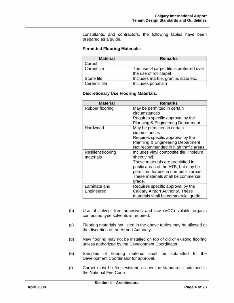
4.1.7 Floors
(a) The Airport Authority will approve all floor materials on a project by project basis. However, in order to assist tenants, design
Calgary International Airport Tenant Design Standards and Guidelines
Section 4 – Architectural
April 2009 Page 4 of 25
consultants, and contractors, the following tables have been prepared as a guide.
Permitted Flooring Materials:
Material Remarks Carpet Carpet tile The use of carpet tile is preferred over
the use of roll carpet Stone tile Includes marble, granite, slate etc. Ceramic tile Includes porcelain
Discretionary Use Flooring Materials:
Material Remarks Rubber flooring May be permitted in certain
circumstances Requires specific approval by the Planning & Engineering Department
Hardwood May be permitted in certain circumstances Requires specific approval by the Planning & Engineering Department Not recommended in high traffic areas
Resilient flooring materials
Includes vinyl composite tile, linoleum, sheet vinyl. These materials are prohibited in public areas of the ATB, but may be permitted for use in non-public areas. These materials shall be commercial grade.
Laminate and Engineered
Requires specific approval by the Calgary Airport Authority. These materials shall be commercial grade.
(b) Use of solvent free adhesives and low (VOC) volatile organic compound type solvents is required.
(c) Flooring materials not listed in the above tables may be allowed at the discretion of the Airport Authority.
(d) New flooring may not be installed on top of old or existing flooring unless authorized by the Development Coordinator.
(e) Samples of flooring material shall be submitted to the Development Coordinator for approval.
(f) Carpet must be fire resistant, as per the standards contained in the National Fire Code.
Calgary International Airport Tenant Design Standards and Guidelines
Section 4 – Architectural
April 2009 Page 5 of 25
(g) The use of flooring material containing asbestos is prohibited. Removal of existing asbestos tile must be done in accordance with Alberta Occupational Health & Safety Standards.
(h) The transition between tenant installed and Landlord base building flooring should occur at a point deemed appropriate by the Landlord.
(i) Where two flooring materials abut, tenants and contractors shall ensure that the finished floor elevations match, and that trip hazards are not created. If necessary, a threshold shall be used.
(j) When cutting existing quarry tile, tenants and contractors shall take necessary precautions to ensure that the cuts are clean, and shall be responsible for the replacement of damaged or chipped tiles.
(k) All grout shall be adequately sealed to prevent discoloration due to accumulation of dirt and grime.
(l) All penetrations through the concrete floor system assembly shall conform to Part 3 of the Alberta Building Code, and will be required to be sealed by a fire stop system as well as waterproofed.
(m) When coring through the floor, spotters must be used below. All measures must be taken to reduce noise and control dust. When coring is required, the Tenant is responsible for obtaining x-rays of the area and submitting the information to the Development Coordinator, prior to work beginning. Use of ultra sound testing is not permitted.
(n) The Landlord has designed the floor slab for all new and existing areas of the Air Terminal Building and within the Leased Premises to receive a maximum dead load of 350 kg/m2 and a maximum live load of 500 kg/m2.
(o) Base building expansion joints within the Leased Premises must be maintained. Any treatment to the expansion joint must be approved by the Development Coordinator prior to installation.
4.1.8 Membranes
Waterproof membranes are to be installed underneath floor finishes in all food and beverage prep and serving areas, washroom facilities etc.
Note: Membranes specified in a) below are specific to waterproofing of the exterior walls of crack isolation and suppression. Coordinate with manufacturers where a membrane is required for continual submersion or
Calgary International Airport Tenant Design Standards and Guidelines
Section 4 – Architectural
April 2009 Page 6 of 25
high moisture drive situations such as in saunas, swimming pools and fountains.
(a) Waterproofing Crack Suppression Membranes: load-bearing, reinforced, liquid applied membrane meeting the requirements of ANSI A118.10:
(i) Acceptable materials:
(1) Custom Building Products Level Quik Waterproof and Anti-Fracture Membrane
(2) Flextile Ltd. Flex WP-980 Waterproof and Crack Isolation Membrane
(3) Laticrete International Inc. 9235 Waterproofing and Anti-Fracture Membrane
(4) MAPEI Inc. PRP 315 Waterproof and Crack Isolation Membrane.
Note: Performed membrane listed below is specifically intended for thin set tile application in shower and other wet areas.
(b) Performed Waterproofing Membrane System: to ANSI A118.10, soft polyethylene membrane with fleece webbing laminated on both sides complete with special cut width rolls and special shapes for corners and pipe sleeves (and manufacturers’ standard floor drain assembly).
(i) Acceptable materials: Schluter Kerdi (and Kerdi Draine) Telephone (403)243-0434, (780)483-8002 or (800)667-8746.
Note: Uncoupling membrane listed below is specifically intended for use in TTMAC 09300 Manual Details 313F and 325F for floors where directly bonding tile or marble to an unstable substrate could lead to failure of the installation. Other types of membranes can be used for this purpose, but these membranes form a part of the total tile setting system and are less susceptible to workmanship irregularities.
(c) Uncoupling Membrane: rigid polyethylene membrane with a grid structure of square cavities 3 mm high each cut back in a dovetail configuration having anchoring fleece laminated to underside (or non-directional, non-deteriorating woven mat (10mm) (16mm) thick) complete with manufacturers recommended floor adhesives and setting materials:
(i) Acceptable materials:
Calgary International Airport Tenant Design Standards and Guidelines
Section 4 – Architectural
April 2009 Page 7 of 25
(1) Schluter Ditra
Telephone (403)243-0434, (780)483-8002 or (800)667-8746.
(2) Laticrete International Inc. (/QSM4) (QSM7) Mat
Telephone (403)253-5150, (790)451-2275 or (800)838-4237.
4.1.9 Walls
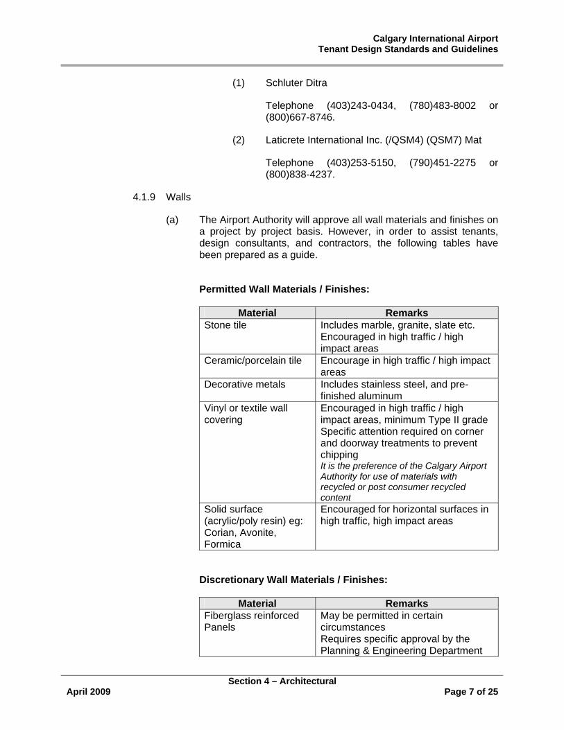
(a) The Airport Authority will approve all wall materials and finishes on a project by project basis. However, in order to assist tenants, design consultants, and contractors, the following tables have been prepared as a guide.
Permitted Wall Materials / Finishes:
Material Remarks
Stone tile Includes marble, granite, slate etc. Encouraged in high traffic / high impact areas
Ceramic/porcelain tile Encourage in high traffic / high impact areas
Decorative metals Includes stainless steel, and pre-finished aluminum
Vinyl or textile wall covering
Encouraged in high traffic / high impact areas, minimum Type II grade Specific attention required on corner and doorway treatments to prevent chipping It is the preference of the Calgary Airport Authority for use of materials with recycled or post consumer recycled content
Solid surface (acrylic/poly resin) eg: Corian, Avonite, Formica
Encouraged for horizontal surfaces in high traffic, high impact areas
Discretionary Wall Materials / Finishes:
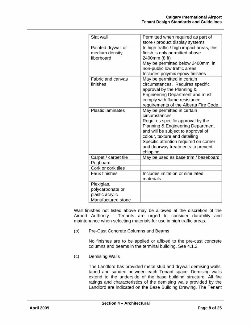
Material Remarks Fiberglass reinforced Panels
May be permitted in certain circumstances Requires specific approval by the Planning & Engineering Department
Calgary International Airport Tenant Design Standards and Guidelines
Section 4 – Architectural
April 2009 Page 8 of 25
Slat wall Permitted when required as part of store / product display systems
Painted drywall or medium density fiberboard
In high traffic / high impact areas, this finish is only permitted above 2400mm (8 ft) May be permitted below 2400mm, in non-public low traffic areas Includes polymix epoxy finishes
Fabric and canvas finishes
May be permitted in certain circumstances. Requires specific approval by the Planning & Engineering Department and must comply with flame resistance requirements of the Alberta Fire Code.
Plastic laminates May be permitted in certain circumstances Requires specific approval by the Planning & Engineering Department and will be subject to approval of colour, texture and detailing Specific attention required on corner and doorway treatments to prevent chipping
Carpet / carpet tile May be used as base trim / baseboardPegboard Cork or cork tiles Faux finishes Includes imitation or simulated
materials Plexiglas, polycarbonate or plastic acrylic
Manufactured stone
Wall finishes not listed above may be allowed at the discretion of the Airport Authority. Tenants are urged to consider durability and maintenance when selecting materials for use in high traffic areas.
(b) Pre-Cast Concrete Columns and Beams
No finishes are to be applied or affixed to the pre-cast concrete columns and beams in the terminal building. See 4.1.2.
(c) Demising Walls
The Landlord has provided metal stud and drywall demising walls, taped and sanded between each Tenant space. Demising walls extend to the underside of the base building structure. All fire ratings and characteristics of the demising walls provided by the Landlord are indicated on the Base Building Drawing. The Tenant
Calgary International Airport Tenant Design Standards and Guidelines
Section 4 – Architectural
April 2009 Page 9 of 25
shall provide all wall treatments within the Leased Premises at the Tenant’s expense.
No wall fixtures directly mounted on the demising walls will be permitted other than those approved by the Landlord. The Tenant acknowledges that the demising walls are not designed to support wall-mounted fixtures. Slatwall panels and metal standards must be independently secured.
(d) Where walls are to be attached to tile floors, attachment must be done at grout lines, where possible.
(e) All drywall is to be a minimum thickness of 16mm, fire rated to the most stringent rating of the National Fire Code.
(f) Where painted drywall is to be used, a paint sample shall be provided to the Development Coordinator for approval. One coat of primer and two coats of colour are required. The use of colours which match or are compatible with those in the surrounding area of the terminal is encouraged.
(g) All studs are to be metal. Wooden studs are strictly prohibited. Wooden blocking shall only be considered when specifically identified on the submitted construction drawings.
(h) All baseboards are to match the colour, type and height of existing adjacent baseboard material.
(i) For all walls which are located adjacent to a public circulation corridor, or in any other area where baggage carts are commonly used, a durable base material shall be installed to a height of 380mm (15”). above the level of the floor. Acceptable store front base materials include:
• stainless steel
• prefinished metals
• stone, quarry or ceramic tile
4.1.10 Doors and Frames
(a) All doors leading from public areas to secure areas, restricted areas, and/or to the outside, shall be insulated metal doors 44mm (1 ¾ ”) thick - suitable for exterior use. Minimum dimension 915mm x 2135 (3’ x 7’ ).
(b) Doors opening into an area must have a vision panel that must not affect fire rating.
Calgary International Airport Tenant Design Standards and Guidelines
Section 4 – Architectural
April 2009 Page 10 of 25
(c) All wooden doors shall be solid core doors 44mm (1 ¾ ”) thick - with heat/pressure applied plastic laminate to match existing Air Terminal Building Standards. Minimum dimension 915mm x 2135 (3’ x 7’ ).
(d) All metal doors shall be painted to match existing.
(e) Glass doors must be safety glass tempered and have a contrasting mark as required by Code.
(f) All locks shall be Schlage L 9000 series, 630 finish c/w 03 lever and type >L= escutcheon.
(g) The Airport Authority may consider the use of Schlage A-series, 626 finish c/w key lockset for interior tenant space doors which do not have public access. Specific approval from the Airport Authority is required in such circumstances. All doors which have public access must comply with f), above, without exception.
(h) All doors shall have 3 hinges per door, of ball bearing type, with non wrought stainless steel, 630 finish, unless provision is to be made to include an electrical access switch.
(i) Door stops shall be used where appropriate; finish 630 (stainless steel, satin finish).
(j) Tenant spaces with doorways opening into post-security areas must be equipped with door closure devices.
(k) All door closures shall be L.C.N. Series Smoothee 4010 or 4110 finish 689 clear or 695 dark bronze.
(l) All door frames to be welded, mitred corners, 1.6mm (16ga) minimum heavy duty galvanized steel, primed and painted to match existing.
(m) All doors in high traffic areas should be equipped with kick plates; finish 630. Kick plates will be a minimum height of 380 mm (15”) pre-security areas and 250 mm (10”) in post security areas.
4.1.11 Windows, Glazing and Coverings
(a) All exterior windows shall be of a thermal pane type and bronze tinted to match existing, in prefinished aluminum frames.
(b) All interior glazing shall conform to Code.
(c) All interior glazing shall be tempered or safety glass, minimum thickness 3/8”, 1/2” recommended.
Calgary International Airport Tenant Design Standards and Guidelines
Section 4 – Architectural
April 2009 Page 11 of 25
(d) All window frames in fire separations shall be of steel painted to match existing.
(e) Existing windows and window frames shall not be removed, altered, or obscured without the prior approval of the Airport Authority.
(f) Any attachments to window frames must be approved by the Airport Authority. Attachment by mechanical means to exterior window frames is expressly prohibited.
(g) Contractors shall take the necessary precautions to ensure that existing metal window frames are not damaged during construction.
(h) All interior window frames shall be prefinished anodized aluminum to match existing.
(i) Airside views from public areas shall be maintained whenever possible.
(j) All window coverings shall match those existing in the area, unless otherwise approved.
(k) All window coverings shall be flame resistant, and comply with the most stringent National Fire Code rating.
4.1.12 Ceilings
Ceilings within the Leased Premises should be constructed in drywall or suspended metal or acoustical tile. Standard 24” x 48” acoustic tile ceiling systems are not allowed within public areas of the Leased Premises. Exposed ceiling systems may be considered at the Landlord’s discretion.
(a) In some cases the Landlord may be required to specify the ceiling material to be used.
(b) All drywall ceiling assemblies shall be a minimum 16mm fire rated gypsum board.
(c) All closed in ceiling assemblies shall provide a minimum one hour fire resistance rating.
(d) All suspended ceiling material should be either acoustic ceiling panels or metal ceiling components. A sample shall be provided prior to installation for approval.
(e) Suspended ceiling systems must conform to all regulatory by-laws and Codes having jurisdiction.
Calgary International Airport Tenant Design Standards and Guidelines
Section 4 – Architectural
April 2009 Page 12 of 25
(f) Any mechanical panel access blocked shall be relocated to a suitable location at the tenant’s expense.
(g) Appropriate access to any mechanical or electrical equipment or fittings shall be provided in all ceiling installations.
(h) Wooden ceiling joists are strictly prohibited.
4.1.13 Roof
(a) All new roof areas shall be Sarnafil single ply membrane inverted system.
(b) Roof installations, repairs, modifications (including penetrations through the roof) are strictly controlled, and shall be undertaken only by a qualified Sarnafil applicator.
(c) Access to roof areas is allowed only under the supervision of a Calgary Airport Authority employee. To arrange access, contact the Manager, Structural Maintenance, 735 1334.
(d) Fall protection systems may not be altered or affected by construction.
4.1.14 Concession/Store Tops
(a) Where the top of a concession is exposed to views from above, the Airport Authority requires that the top of the concession/store be finished. Designs and materials which are consistent with the architectural detail of both the concession/store and the Air Terminal Building, and which require minimum maintenance should be used.
(b) No conduit, wiring, plumbing or mechanical apparatus shall be visible from above or below.
(c) No storage is permitted on concession/store tops.
(d) Concession/store tops should be designed so as to allow minimal accumulations of dust and debris.
(e) All concession/store tops shall be maintained and cleaned on a regular basis.
4.2 Lighting
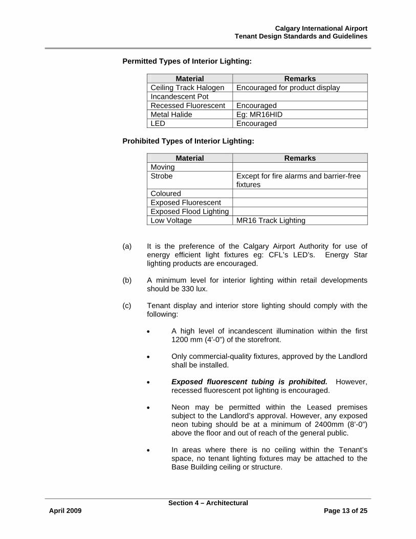
4.2.1 The Airport Authority will approve all lighting materials and fixtures on a project by project basis. However, in order to assist tenants, design consultants, and contractors, the following tables have been prepared as a guide.
Calgary International Airport Tenant Design Standards and Guidelines
Section 4 – Architectural
April 2009 Page 13 of 25
Permitted Types of Interior Lighting:
Material Remarks Ceiling Track Halogen Encouraged for product display Incandescent Pot Recessed Fluorescent Encouraged Metal Halide Eg: MR16HID LED Encouraged
Prohibited Types of Interior Lighting:
Material Remarks Moving Strobe Except for fire alarms and barrier-free
fixtures Coloured Exposed Fluorescent Exposed Flood Lighting Low Voltage MR16 Track Lighting
(a) It is the preference of the Calgary Airport Authority for use of energy efficient light fixtures eg: CFL’s LED’s. Energy Star lighting products are encouraged.
(b) A minimum level for interior lighting within retail developments should be 330 lux.
(c) Tenant display and interior store lighting should comply with the following:
• A high level of incandescent illumination within the first 1200 mm (4'-0") of the storefront.
• Only commercial-quality fixtures, approved by the Landlord shall be installed.
• Exposed fluorescent tubing is prohibited. However, recessed fluorescent pot lighting is encouraged.
• Neon may be permitted within the Leased premises subject to the Landlord’s approval. However, any exposed neon tubing should be at a minimum of 2400mm (8’-0”) above the floor and out of reach of the general public.
• In areas where there is no ceiling within the Tenant’s space, no tenant lighting fixtures may be attached to the Base Building ceiling or structure.
Calgary International Airport Tenant Design Standards and Guidelines
Section 4 – Architectural
April 2009 Page 14 of 25
4.3 Signage Requirements
The following general signage requirements apply to all tenants.
4.3.1 General
Tenant identification is an integral element of the overall design and image of the Tenant’s business. Signage should be unique, distinctive and graphically creative. Storefront signs should be compatible with the overall tenant design and should be of a compatible size, colour and illumination. Tenant signs should be visible but not so vivid as to overwhelm adjacent tenant signs or the Airport Way Finding Signage.
All signage installations require Airport Authority approval. All signage associated with a proposed development must be submitted as a comprehensive package and shall be included as part of the initial submission.
The Airport Authority will approve all sign design, materials and finishes on a project by project basis. However, in order to assist tenants, design consultants and contractors, the following tables have been prepared as a guide.
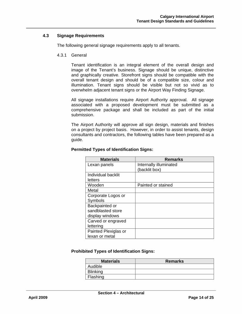
Permitted Types of Identification Signs:
Materials Remarks Lexan panels Internally illuminated
(backlit box) Individual backlit letters
Wooden Painted or stained Metal Corporate Logos or Symbols
Backpainted or sandblasted store display windows
Carved or engraved lettering
Painted Plexiglas or lexan or metal
Prohibited Types of Identification Signs:
Materials Remarks Audible Blinking Flashing
Calgary International Airport Tenant Design Standards and Guidelines
Section 4 – Architectural
April 2009 Page 15 of 25
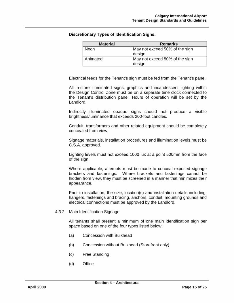
Discretionary Types of Identification Signs:
Material Remarks Neon May not exceed 50% of the sign
design Animated May not exceed 50% of the sign
design
Electrical feeds for the Tenant’s sign must be fed from the Tenant’s panel.
All in-store illuminated signs, graphics and incandescent lighting within the Design Control Zone must be on a separate time clock connected to the Tenant’s distribution panel. Hours of operation will be set by the Landlord.
Indirectly illuminated opaque signs should not produce a visible brightness/luminance that exceeds 200-foot candles.
Conduit, transformers and other related equipment should be completely concealed from view.
Signage materials, installation procedures and illumination levels must be C.S.A. approved.
Lighting levels must not exceed 1000 lux at a point 500mm from the face of the sign.
Where applicable, attempts must be made to conceal exposed signage brackets and fastenings. Where brackets and fastenings cannot be hidden from view, they must be screened in a manner that minimizes their appearance.
Prior to installation, the size, location(s) and installation details including: hangers, fastenings and bracing, anchors, conduit, mounting grounds and electrical connections must be approved by the Landlord.
4.3.2 Main Identification Signage
All tenants shall present a minimum of one main identification sign per space based on one of the four types listed below:
(a) Concession with Bulkhead
(b) Concession without Bulkhead (Storefront only)
(c) Free Standing
(d) Office
Calgary International Airport Tenant Design Standards and Guidelines
Section 4 – Architectural
April 2009 Page 16 of 25
(a) Bulkhead
• At some locations, the Landlord has provided a continuous drywall sign band on each storefront elevation.
• Main identification signage mounted on the drywall sign band must not project lower than 2400 mm (8 ft) above the level of the floor.
• The length of any sign may not exceed 66% of the storefront width.
• Letter signs should be in proportion to the size of the sign band and should not exceed an average height of 450mm (18”).
• The maximum projection of an individual letter sign’s outer edge beyond the sign band/bulkhead fascia is 150mm (6”).
• At the Landlord’s discretion, the Tenant may be allowed to install a three dimensional sign that projects a maximum 300 mm (12”) in any direction beyond the Tenant’s sign bulkhead.
• At the Landlord’s discretion, the Tenant may be allowed in addition to the storefront sign to install a blade sign. The size, design, material finish and mounting details are subject to the Landlord’s approval.
• All through-wall neon should be contained in CSA approved metal housings with the front lip cut off flush with the signband/bulkhead face. Neon tube supports should not be fastened to the sign band or bulkhead- all supports should be within the letter figure or symbol. Support fastenings, such as screws and bent angles should be of a non-corrosive material or coating.
(b) Storefront
• Painted or applied signs on the surface of a glass storefront in a method approved by the Landlord.
• Sandblasted, etched or beveled glass with a concealed light source.
• Individual metal letters applied to the surface of a glass storefront (maximum height 150mm (6”), minimum height 50mm (2”).
Calgary International Airport Tenant Design Standards and Guidelines
Section 4 – Architectural
April 2009 Page 17 of 25
• The length of any sign shall not exceed 66% of the store front width, with a maximum letter height of 450mm.
(c) Free Standing
Free standing identification signage is only permitted when the tenant is unable to attach signage to a wall or bulkhead. Free standing signage will be reviewed and approved by the Calgary Airport Authority on a project by project basis.
(d) Office
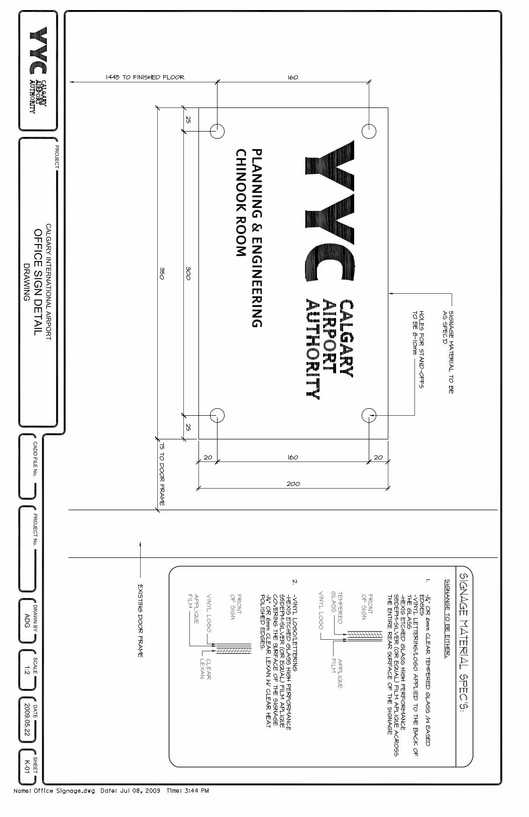
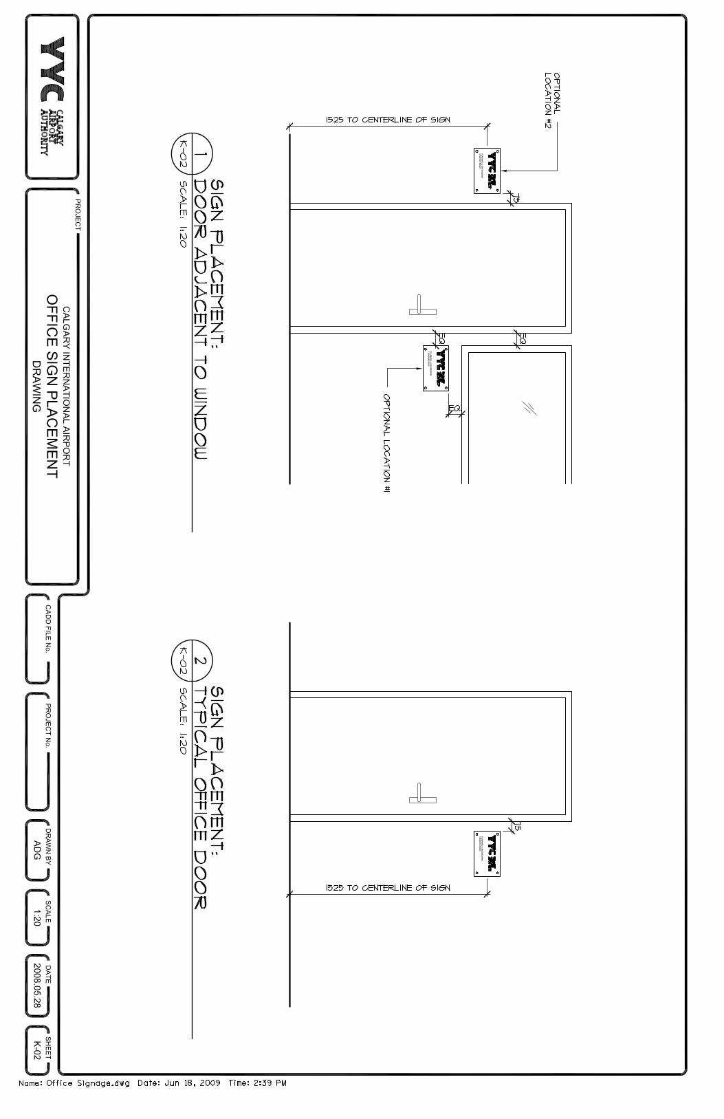
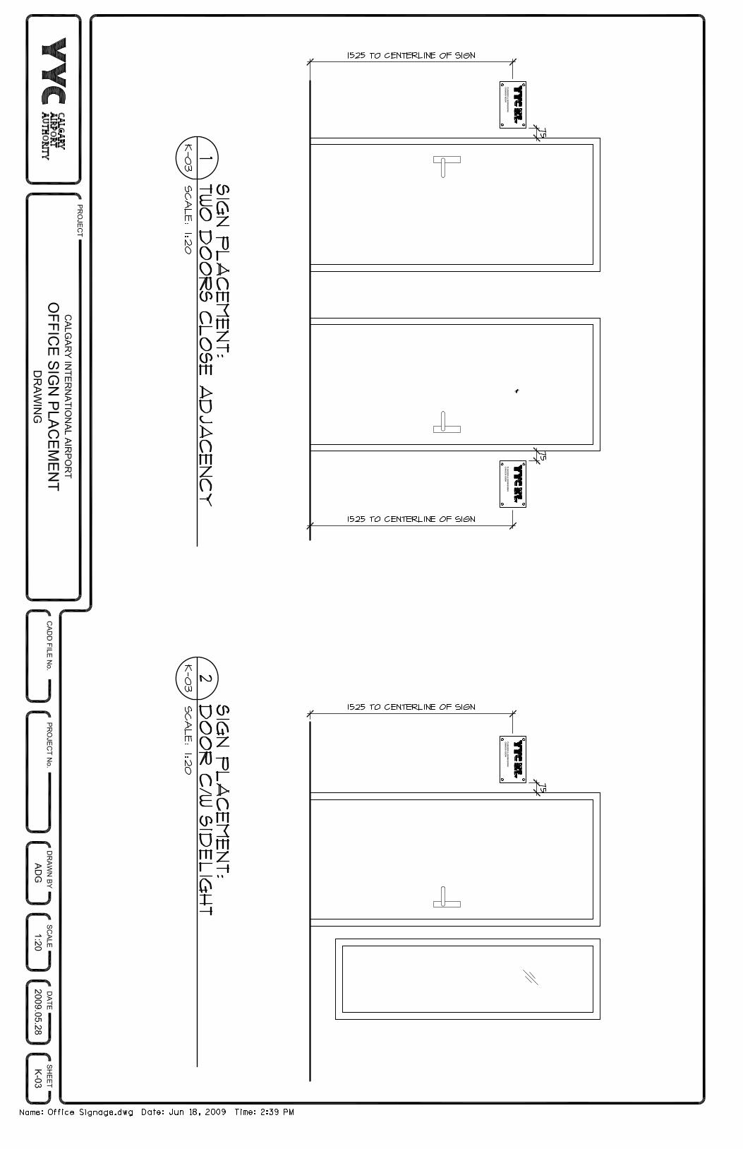
Please reference Appendix K for Office identification signage detail and placement.
4.3.3 Blade
In the case where the Landlord has approved a storefront blade sign, the Tenant must follow the following guidelines:
• All details of the sign, location and fastening details are subject to the Landlord’s approval.
• Blade signs must be non-illuminated with a maximum face of 600 mm x 600 mm, mounted perpendicular to the storefront.
Blade signs may be:
• Painted with a low lustre paint in a method approved by the Landlord;
• Individual or script lettered, non-illuminated – maximum height 450 mm (18”), minimum height 100 mm (4”);
• A wood panel with raised letters or logo;
• An engraved or etched stone or metal plaque;
• A non-illuminated Artisan’s plaque.
The use of illuminated blade signs may be approved in areas where they do not interfere with airport wayfinding signs.
4.3.4 Promotional and Temporary Signage
Promotional signs are permitted provided they are of a temporary nature. Permanent Promotional signs are not permitted.
All signs, graphics and logos must receive the Landlord’s approval prior to installation.
Calgary International Airport Tenant Design Standards and Guidelines
Section 4 – Architectural
April 2009 Page 18 of 25
Free-standing signs are not permitted outside the Leased Premises.
The Tenant should not erect or affix any sign or advertisement to the exterior of the Leased Premises including windows and doors, without the Landlord’s approval.
Advertising slogans and/or product identification signs are not permitted outside of the Lease Line.
Additional types of identification signage may be considered. Each request will be reviewed on a case by case basis and approval will be dependent upon whether the proposed identification sign adheres to a number of basic considerations including type, height, size and location.
4.4 Official Languages Policy
The Calgary Airport Authority Official Languages Policy is based upon the provisions of Bill C (Airport Transfer (Miscellaneous Matters) Act), the Official Languages Act (Parts IV, V, VI, VIII, IX and X), and the Official Languages (Communication with and Services to the Public) Regulations. Tenants are responsible for ensuring that the Official Languages Policy and any future policy regulations and/or amendments are enforced.
With respect to tenant signage, the following regulations apply:
All signage (electronic or static) except registered names or logos, displayed in public areas must be provided in both official languages.
Those organizations that are specifically identified in the Official Languages Regulations as providing specified services to the travelling public through a contractual agreement with the Calgary Airport Authority, must provide them in both official languages. This applies to the following services:
• restaurants, cafeteria, fast food outlets, car rental agencies, travel insurance, ground transportation dispatch, foreign exchange, duty free shops and hotel services;
• self-service equipment, including automated banking machines and vending machines, and the provision of instructions for the use of public telephones and electronic games: and
• passenger screening and boarding services, public announcements and the provision of other information to the public, and carrier services, including counter services for ticket and check-in.
Where a service is provided by means of printed or pre-recorded material, such as signs, notices and menus, car rental contracts and travel insurance policies for the travelling public, the material shall be provided in both official languages.
Calgary International Airport Tenant Design Standards and Guidelines
Section 4 – Architectural
April 2009 Page 19 of 25
Where a service is provided by means other than those referred to above, the service shall be offered to the travelling public by such means as will enable any member of that public to obtain those services in the official language of his or her choice, within a reasonable period of time.
4.5 Barrier Free Design Requirements
In addition to providing sufficient in-store circulation for luggage carts and passengers with hand luggage, Tenants must comply with the Alberta Building Code and National Building Code requirements for barrier-free design.
The Alberta Building Code and National Building Code have set standards for barrier free design with which the Tenant’s designers must comply especially within all retail areas, lounges and restaurants. Particular attention must be paid to storefront entrances, paths of travel, in-store and entrance floor level changes, washrooms accessible to the public, doorways and doors, aisle widths, counter heights and widths, eye level displays, food and beverage seating and signage information.
4.6 Free–standing Kiosks
The Airport Authority defines a Free-Standing Kiosk as a retail unit without demising walls and bulkhead.
Kiosks are to be constructed and installed by the Tenant. The design is to be approved by the Landlord.
4.6.1 Design Guidelines
Counters should be on average 900 mm (3’-0”) in height with provision made for barrier free accessibility.
Display cases may occupy up to thirty percent (30%) of the counter area and should not exceed 1370 mm (4’-6”) in height.
Counter fronts should be constructed of durable, high quality materials consistent with the overall kiosk design and be compatible with the materials and design of the Airport. Counter fronts should incorporate a continuous 250mm (10”) high protective base. Refer to Retail Store Design Controls (item 4.7) for approved finishes.
Canopies and overhead structures should be designed as an integral part of the kiosk. Internally illuminated materials are not permitted and the structure should be designed to hold the kiosk signage and lighting.
The horizontal bottom edge of the kiosk canopy should be at a minimum 2250 mm (7’-6”) above the floor.
Overhead structures such as canopies should be constructed of durable, high quality materials.
Calgary International Airport Tenant Design Standards and Guidelines
Section 4 – Architectural
April 2009 Page 20 of 25
Where required, kiosk tenants are responsible for the provision of adequate refuse containers. Refuse containers should be built into the kiosk and enclosed in a manner consistent with the design of the kiosk.
Each kiosk must have at least one primary identification sign. The sign should be integral to the design of the canopy with a maximum letter height of 300 mm (12”) and should not exceed 1200 mm (4’-0”) in length. The method of construction and attachment to the kiosk is subject to the Landlord’s approval.
All kiosk lighting should be within the leased space and directed towards the products. Task lighting should be focused on countertops and work areas; display lighting should be focused on the products.
Display cases should be internally illuminated.
Security systems or closures should be designed to be integral with the structure and constructed in materials that are consistent with the kiosk design
Power and water lines must be cored through the base building floor slab to a fixed stub location within the kiosk.
Note: Kiosk Tenants should not rely upon the Base Building HVAC system to ventilate their unit. To avoid potential ventilation problems within their unit, Kiosk Tenants should refer to item 5.2.
4.7 Retail Merchandising Units (RMU’s)
INFORAMTION REQUIRED
4.8 Vending/Amusement Machines
Vending machines, when approved by the Airport Authority, shall be located so as not to impede the flow of traffic. The size and location of all machines must be approved in writing by the Airport Authority prior to installation.
Vending or amusement machines may not exceed a noise level of 85 db at any given time.
Unless otherwise approved by the Airport Authority, all machine enclosures should have a 380mm (15”) high stainless steel base to protect the machines from baggage cart damage.
4.9 Displays
Permanent or temporary displays must be approved by the Airport Authority prior to installation.
Calgary International Airport Tenant Design Standards and Guidelines
Section 4 – Architectural
April 2009 Page 21 of 25
Permanent or temporary displays when approved by the Airport Authority shall be located so as to not impede the flow of traffic in the Public Concourse or interfere with sightlines to the Terminal Wayfinding system.
In the case where the display is manned, no solicitation of the public or Airport staff will be permitted.
Displays should be designed to compliment the design theme of the area in which the display is located. Special attention should be taken in the use of shapes, colours and materials.
4.10 Food & Beverage Units – In-line
The merchandising concept for in-line food units is to create a strong visual identification of the Tenant’s product by stressing the presentation of cooking and food preparation. Storefronts should be open allowing maximum exposure of the Premises. Stores and storefronts are to be constructed by the Tenant. All designs are to be approved by the Landlord.
In addition to the design standards contained in the previous sections the following are specific to In-line Food & Beverage Tenants:
4.10.1 Counters
Tenant counters should average 900 mm (3’-0”) in height and not exceed 1370 mm (4’ 6”) in the case of display cases and sneeze guards. Counter fronts should incorporate a continuous 250mm (10”) high protective base where exposed to the public concourse, 380mm (15”) in pre-security areas, and provision must be made for barrier free accessibility.
Tray rails and/or tray storage should be incorporated into the counter design and should not project beyond the Lease Line. Counters should be fabricated with solid edges.
Self-serve drink dispensers and waste receptacles must be self-contained within the unit.
4.10.2 Railings
Railings within the Tenant’s space should be finished in durable materials such as powder coated metal, stainless steel, brass, natural wood or tempered glass. Railings must be installed within the Tenant’s leased premises. The Airport Authority will approve all railing material and finishes on a project by project basis.
The installation of railings without prior approval from the Calgary Airport Authority is strictly prohibited.
Calgary International Airport Tenant Design Standards and Guidelines
Section 4 – Architectural
April 2009 Page 22 of 25
4.10.3 Lighting
Lighting in general should be designed to enhance the food presentation by means of incandescent and accent lighting. Exposed fluorescent lighting within the public service areas is not allowed.
4.10.4 Exhaust Hoods
Exhaust hoods, exposed to the public view should be clad in visually acceptable materials such as stainless steel or copper.
4.10.5 Prep kitchen and rear Service Areas
Prep kitchens and rear service areas should not be visible to the public. Doors should have self-closing devices.
Tenants are required to keep all supplies and stock out of public view.
4.10.6 Menu Boards
All menu boards should be illuminated, either internally or indirectly.
Menu boards should be located under the bulkhead within the Tenant’s Premises.
Menu boards may not be hung from the ceiling directly in front of the storefront bulkhead.
Menu text must be presented in both English and French, please reference Section 4.4 (Official Languages Policy).
Free-standing menu boards or other free-standing signs are not allowed without prior written consent of the Landlord.
4.10.7 Floor Membranes
All areas with the potential for water leakage are to have a waterproof floor membrane – please reference Section 4.1.8.
4.11 Food & Beverage Units – Dining Lounge
Sit down dining and lounge units should be open and inviting to the public circulation areas and provide a variety of dining and lounge experiences in a contemporary atmosphere. All designs are to be approved by the Landlord.
In addition to the design standards contained in the previous sections the following are specific to In-line Food & Beverage Units – Dining Lounge Tenants:

Calgary International Airport Tenant Design Standards and Guidelines
Section 4 – Architectural
April 2009 Page 23 of 25
4.11.1 Design Guidelines
All finishes should be durable and of good quality such as tile, metal, glass, natural wood, stone or other materials approved by the Landlord. Floor finishes within the Leased Premises are limited to natural wood, high performance commercial carpet, slate, porcelain or ceramic tile, textured or tinted concrete, natural stone, terrazzo or other durable materials acceptable to the Landlord.
Enclosure handrails are subject to the Landlord’s approval and low walls should incorporate a 250mm (10”) high protective base where exposed to the Public Concourse, 380mm (15”) in pre-security areas.
Prep Kitchens and storage areas should not be visible to the public. Doors should have self-closing devices. Open kitchens are subject to the Landlord’s approval.
Refer to General Architectural Standards (4.1 and sub sections) for approved storefront and closure systems.
Where applicable, airside views at exterior glazed walls should be maintained.
Under floor piping for syrup and/or liquor lines to bars and beverage areas will only be permitted with the Landlord’s approval.
Durable floor finishes must be installed, properly treated and sealed under all bar areas before equipment is installed.
Refer to General Architectural Standards (4.1 and sub sections) for approved floor, wall and ceiling finishes.
Refer to General Architectural Standards (4.2 and sub sections) for lighting guidelines.
4.11.2 Sign Guidelines
Refer to Signage Requirements, item 4.3.
4.11.3 Floor Membranes
All areas with the potential for water leakage are to have a waterproof floor membrane – please reference Section 4.1.8.
4.12 Food & Beverage - Free-standing Kiosks
Strategically located free-standing feature units are an important design element within the retail areas of the Airport. The Landlord has identified specialized food and beverage tenants to be located throughout the Terminal Building. These tenants will be required to design a unit that is unique to the retailer and the
Calgary International Airport Tenant Design Standards and Guidelines
Section 4 – Architectural
April 2009 Page 24 of 25
Airport environment. Specific attention to detail will be paid to these units during the Landlord’s review and approval process.
In addition to the design standards contained in the previous sections the following are specific to In-line Food & Beverage – Free-standing Kiosk Tenants:
4.12.1 Design Guidelines
The unit should be visually open, allowing clear visibility through all sides.
All counters and partitions should be no greater than 1370 mm (4’-6”) in height. Counter fronts should incorporate a 250mm (10”) high protective base where exposed to the Public Concourse, 380mm (15”) in pre-security areas and provision must be made for barrier free accessibility.
All elements greater than 1200 mm (4’-0”) in height such as lighting and signage shall be designed so as to be visually open and unobtrusive.
The entire unit will be considered to be within the Design Control Zone and subject to the Landlord’s approval.
Countertop materials must be durable and of a high quality. The Tenant is encouraged to add decorative elements such as a wood or metal bullnose or another decorative accent band along the face of the countertop. Acceptable materials are: solid surface plastic (Corian, Surell or equal), stone, metal, and stainless steel
Sneeze guards should be designed to be an integral part of the kiosk and should be no higher than 1370mm (4’-6”) above the finished floor. Joints should be butt glazed to allow maximum visibility.
Cup and napkin dispensers and condiment containers should be recessed into the countertop as an integral part of the design
Menu boards should be of high quality durable materials with finished or framed edges and attached in a professional manner to the kiosk, the equipment or other elements of the kiosk. Internally illuminated menu boards are not permitted.
In the case where table seating is provided adjacent to the kiosk, the Tenant should define the seating area by means of a railing or low wall. See item 4.10.2 (Railings).
Power and water lines must be cored through the base building floor slab to a fixed stub location within the kiosk. Such work will be carried out by the Landlord’s forces at the Tenant’s expense.
4.12.2 Sign Guidelines
Refer to Free-standing Kiosks item 4.6.
Calgary International Airport Tenant Design Standards and Guidelines
Section 4 – Architectural
April 2009 Page 25 of 25
4.12.3 Floor Membranes
All areas with the potential for water leakage are to have a waterproof floor membrane – please reference Section 4.1.8.
Calgary International Airport Tenant Design Standards & Guidelines
Section 5 – Mechanical
April 2009 Page 1 of 9
5.0 BASE BUILDING MECHANICAL STANDARDS AND GUIDELINES
5.1 General
5.1.1 Existing Conditions
(a) In specific locations the Calgary Airport Authority (“Landlord”) has established certain fixed Base Building mechanical services that pass through the Leased Premises. Any connection changes or modifications to existing base building services, including structural items, within the Leased Premises shall be reviewed with the Development Coordinator and the Landlord’s written approval must be obtained before any work is done.
(b) Except for redundant in-store ductwork associated with heating and cooling an existing premise scheduled for renovation, the Tenant shall not remove, alter or relocate any other in-store ductwork without the prior consent of the Landlord.
(c) Any changes or modifications to existing base building services, including structural items, within the Leased Premises shall be reviewed and approved by Landlord before any work is done.
(d) For specific use applications (e.g. food courts, kitchens & washrooms) the Tenant is required to install a waterproof membrane on the floor. Where a waterproof membrane exists, Landlord approved methods for repairs shall be used to maintain a watertight seal after construction/renovation. Please reference Section 4.1.8.
(e) The Landlord must approve any work which may affect the base building warranties, before any work can commence.
(f) Where construction involves the modification of an existing control system, the tenant’s contractor shall co-ordinate the installation of all control components required to provide a fully operational system including the replacement of existing defective components, with the Calgary Airport Authority.
(g) The Landlord has supplied connections to the base building systems at designated points within the Lease Premises as identified on the Base Building Drawing. The Landlord has designated the capacity for general lighting, occupant load and miscellaneous equipment load within the Leased Premises at an average of 15 watts per square foot.
(h) It is the responsibility of the Tenant’s contractors and designers to check and verify actual on-site dimensions and conditions.
Calgary International Airport Tenant Design Standards & Guidelines
Section 5 – Mechanical
April 2009 Page 2 of 9
(i) All existing wall penetrations within the Leased Premises must be fire stopped as required using only firestop products that have been ULC or cUL tested for specific fire-rated construction conditions conforming to construction assembly type, penetrating item type, annular space requirements, and fire-rating involved for separate instance. Install firestop materials in accordance with ULC Fire resistance Directory or UL Products Certified for Canada (cUL) Directory.
(j) All existing floor penetrations within the Leased Premises must be fire stopped and sealed with a watertight membrane using only firestop products that have been ULC or cUL tested for specific fire-rated construction conditions conforming to construction assembly type, penetrating item type, annular space requirements, and fire-rating involved for separate instance. Install firestop materials in accordance with ULC Fire resistance Directory or UL Products Certified for Canada (cUL) Directory.
(k) All existing plumbing cleanouts within the Leased Premises must be relocated to floor level at the Tenant’s expense.
5.1.2 Demolition of Existing Mechanical Systems
(a) Any plumbing and / or mechanical equipment which is no longer required by the Tenant or is to be abandoned must be removed. Removal shall extend to the last valve, tee (“T”) or wye (“Y”) connection. Refer to shutdown procedures.
(b) Pneumatic tubing no longer required by the Tenant or to be abandoned must be stripped back to the main and capped.
(c) The Tenant is responsible for the repair or patching of all floors, walls, etc. damaged as the result of the removal of any equipment. New materials should be used to match the existing condition.
(d) Pipes and systems that are no longer required that are removed are to be noted as being removed on a set of record drawings. Such drawings shall be submitted to the Calgary Airport Authority.
5.1.3 Cutting & Patching
(a) Prior to undertaking any floor penetrations approved by the Landlord, the tenant is required to X-ray the floor area in question to determine locations of any in-slab re-bar and/or conduit. Copies to be provided to the Landlord. X-raying of any floor area within the Leased Premises should be done after normal operating hours and all precautions should be made to
Calgary International Airport Tenant Design Standards & Guidelines
Section 5 – Mechanical
April 2009 Page 3 of 9
protect any adjacent computer equipment. Refer to shutdown procedures.
(b) Mechanical coring must be undertaken for slab penetrations greater than 25 mm (1”) in diameter.
(c) Provide sleeves for all wall and floor penetrations.
(d) All wall and floor penetrations must be sealed to the Landlord’s satisfaction. All penetrations must be fire-proofed as required and all floor penetrations must have a watertight seal. See items 5.1.1.i and 5.1.1.j.
5.1.4 Shop Drawings
(a) One (1) set of approved shop drawings must be submitted to the Development Coordinator for all specified Tenant equipment as per the approved drawing submission.
5.1.5 Standard of Materials and Workmanship
(a) The Tenant’s contractor must employ tradesmen properly licensed and qualified to perform the specified work.
5.1.6 Owner’s Stock
(a) Existing equipment not intended to be re-used shall be disposed of by the tenant .
5.1.7 As-Built Drawings
(a) Refer to Section 9.0, Final Inspection and Clean Up.
5.1.8 Coordination of Services
(a) The Tenant or his contractor must coordinate the locations of all existing services with the Development Coordinator and Mechanical Coordinator prior to the commencement of any work on site.
(b) All Contractors / Tenants are required to complete a Building Services Shutdown Request Form to arrange for equipment to be isolated prior to work commencing.
Shutdown forms are available on the Calgary International Airport’s webpage (www.yyc.com) or from the Planning & Engineering office. Shutdown requests must be submitted 48 hours prior to requested time of shutdown.
The following require completion of a Building Services Shutdown Form:
Calgary International Airport Tenant Design Standards & Guidelines
Section 5 – Mechanical
April 2009 Page 4 of 9
(i) To isolate, drain & refill the heating and fire protection systems.
(ii) To isolate domestic water supplies.
(iii) HVAC systems.
(iv) Gas service.
(v) Removal of thermostats, air boxes, or any pneumatic air lines.
5.1.9 Performance Tests
(a) The Tenant is required to undertake performance tests for all mechanical and electrical equipment and systems installed within the Leased Premises to ensure proper operation and that all requirements have been met. Written documentation of the performance tests must be submitted to the Landlord prior to the Landlord’s acceptance of the work.
5.1.10 Air and Water Balancing
(a) The Tenant will provide air and water balancing of the Tenant’s HVAC and exhaust system upon notification from the Tenant that the Tenant’s system. A copy of the approved report must be added to the Maintenance Manual (see 5.7.1.c)
5.1.11 Painting and Identification
(a) All piping shall be identified by black painted labels and directional flow arrows. Identification shall be provided at fifty (50) foot (15000mm) intervals, on both sides of a wall/floor penetration and behind access doors using the Calgary Airport Authority’s colouring and labeling specifications. See Appendix ‘F’.
5.1.12 Fire Separations and Fire Dampers
(a) The Tenant must provide and maintain all fire and smoke separations and fire dampers within the Leased Premises and between adjacent tenancies and the base building as required by the Alberta Building Code and the Alberta Fire Code. See item 5.1.1.i).
(b) The Tenant must provide and maintain watertight seals around all pipes and duct penetrations through designated smoke or fire separations. See item 5.1.1.j).
5.2 Ductwork and Accessories
Calgary International Airport Tenant Design Standards & Guidelines
Section 5 – Mechanical
April 2009 Page 5 of 9
5.2.1 General
(a) The Tenant must provide adequately sized access panels for dampers, equipment, fire dampers, valves, radiation valves, and any other equipment requiring servicing.
(b) The Tenant must verify with the Landlord, the location, size, and quantity of access panels required prior to construction.
5.2.2 Heating, Ventilating and Air Conditioning
(a) The air distribution within the Leased Premises shall be installed by the Tenant and should include ductwork, dampers, diffusers, grilles, and 25mm (1”) thermal insulation with a vapor barrier.
(b) Any air tempering and/or zone control with an electrical heat source proposed by the Tenant is subject to the Landlord’s approval and will be at the Tenant’s expense.
(c) Zone control within the Leased Premises shall be provided by modifying existing radiation heating systems.
(d) Aluminum or steel jackets shall be provided for all outdoor piping and ducting.
(e) All exposed piping and ducting canvas jackets shall be painted.
(f) The Tenant shall use rigid rectangular ductwork. Flex duct will only be allowed for low pressure duct drops to a maximum of 1000mm (3’-0”) in length. All ductwork shall be installed as per SMACNA and ASHRAE standards.
(g) Duct tape shall not be used to seal any ductwork.
(h) Ventilation will be provided by the Landlord to satisfy the minimum requirements for the Tenant’s use. The Landlord may install additional exhaust or ventilation at the Tenant’s request and expense.
(i) Where water-cooled equipment is permitted for cooling, Tenants are required to insulate all pressure drain lines.
5.2.3 Exhaust / Make-Up Air
(a) The Tenant is required to exhaust all odours or substances, which, in the Landlord’s opinion, are objectionable. Exhaust hoods shall be provided as per Code requirements or as determined by the Landlord’s Engineer.
(b) Exhaust systems, including exhaust fans and hoods, shall be installed as per current NFPA Codes. Use of a sprinkler system
Calgary International Airport Tenant Design Standards & Guidelines
Section 5 – Mechanical
April 2009 Page 6 of 9
for hood extinguishing is not acceptable. Only CO2 or chemical extinguishing systems are permitted.
(c) Food and Beverage Tenants must provide water washed exhaust hoods over cooking areas complete with an automatic fire protection system and grease interceptor.
(d) The Landlord, will install a tie-in to the Landlord’s Fire Alarm System at the Tenant’s expense. See item 6.9
(e) It is the responsibility of the tenants to supply and install their own make-up air system. The make-up air system is to be tempered and sized for 95% of the Tenant exhaust requirements. A common area unit will provide the remaining 5% of make-up air.
5.3 Gas
5.3.1 General
(a) Tenant gas meters are to be located in the Landlord’s Meter Room. Tenant gas lines are to be extended from the Landlord’s manifold to the Leased Premises at the Tenant’s expense.
5.4 Plumbing
5.4.1 General
(a) All Tenant equipment shall be installed in the Leased Premises by the Tenant.
(b) Vacuum breakers and backflow preventers must be installed by the Tenant on all plumbing lines as required by Code and the Calgary Airport Authority.
(c) Adequately sized access panels for valves, cleanouts, and any other equipment requiring servicing must be provided by the Tenant.
(d) All domestic hot water shall be generated locally by the Tenant.
(e) A domestic cold water supply, sanitary pipes and venting will be provided by the Landlord to the lease line of the Leased Premises. The Tenant must extend these lines at his expense.
(f) All copper piping should be type ‘L’ or ’K’. All vent lines shall be DWV copper or cast iron. Plastic piping will not be permitted.
(g) Exposed piping canvas jackets must be painted.
Calgary International Airport Tenant Design Standards & Guidelines
Section 5 – Mechanical
April 2009 Page 7 of 9
(h) Domestic hot water shall be electrically generated by the Tenant within the Leased Premises. Natural gas water heaters may be permitted for higher user Tenants at the Landlord’s discretion. If permitted, venting must be provided as per Code requirements.
(i) Tenant shall provide a domestic cold water meter with a remote read out. Meter must be mounted no more than 1500 mm (5 ft) above finished floor.
(j) Grease interceptors and/or “hair” baskets shall be surface mounted and installed by the Tenant where required by Code or as determined by the Landlord’s engineer.
(k) All cleanouts shall be installed above the floor level and shall be provided with adequately sized access panels.
5.5 Fire Protection
5.5.1 Sprinkler System
(a) The Landlord has installed a sprinkler system grid within the open ceiling space of each retail unit.
(b) The Landlord’s contractor will perform the interconnection of the Tenant’s sprinkler system to the base building fire alarm system at the tenant’s expense.
5.6 Controls
5.6.1 Control Components
(a) Control valves and dampers shall be equal to the base building standard type unless otherwise noted.
(b) Computer automated controls shall be of the same manufacturer as the base building standard.
(c) The Calgary Airport Authority recommends that all mechanical units be DDC operated and tied-into the Landlord’s Building Management System. All tying-in shall be at the tenant’s expense. The Landlord will not monitor premises not tied into the Landlord’s system.
5.7 Operation and Maintenance Manuals
5.7.1 General
(a) The Tenant must provide manuals of all mechanical systems including operating maintenance and lubrication instructions to the Landlord upon completion of the work.
Calgary International Airport Tenant Design Standards & Guidelines
Section 5 – Mechanical
April 2009 Page 8 of 9
(b) The Tenant must provide the Landlord with certification of all equipment where required by local codes and authorities.
(c) The Tenant must provide the Landlord with copies of all shop drawings, maintenance bulletins and air balance reports.
(d) The Tenant must provide the Landlord with a list of addresses and twenty-four (24) hour contact telephone numbers of all equipment suppliers and contractors.
(e) The Tenant must provide the Landlord with performance details for all equipment including curves for fans and pumps with actual operating points noted and the control sequence of operations.
(f) All of the above information is required by the Landlord to determine the impact on the ATB systems.
5.8 Equipment Maintenance
5.8.1 Mechanical Equipment Installed by Tenant
(a) The Tenant must provide the Landlord with a complete list of all equipment installed within the Leased Premises.
(b) The Tenant at their expense shall maintain all mechanical equipment installed by the Tenant over and above the Base Building services provided by the Landlord. Maintenance tasks and frequencies shall be adequate to ensure that all equipment is operating at the capacity to which it was designed. Proof of adequate maintenance shall be provided to the Landlord if requested.
(c) If in the landlord’s opinion maintenance is inadequate the landlord may have the maintenance performed by an outside contractor and back charged to the Tenant.
5.9 Grease Interceptors
(a) Grease interceptors shall be cleaned and serviced by the tenant as frequently as determined by the Landlord, at a minimum once monthly. All cleaning and servicing shall be carried out during off hours by qualified personnel.
(b) If in the landlord’s opinion maintenance is inadequate the landlord may have the maintenance performed by an outside contractor and back charged to the Tenant.

Calgary International Airport Tenant Design Standards & Guidelines
Section 5 – Mechanical
April 2009 Page 9 of 9
5.10 Kitchen Exhaust Fans
5.10.1 Kitchen exhaust fans shall be cleaned by the Tenant on a regular basis in accordance with NFPA guidelines.
5.10.2 If in the landlord’s opinion maintenance is inadequate the landlord may have the maintenance performed by an outside contractor and back charged to the Tenant.
Calgary International Airport Tenant Design Standards & Guidelines
Section 6 - Electrical
April 2009 Page 1 of 6
6.0 BASE BUILDING ELECTRICAL STANDARDS AND GUIDELINES
6.1 General
6.1.1 ELECTRIAL WORK MUST NOT BE CARRIED OUT ON ENERGIZED EQUIPMENT.
All Contractors / Tenants are required to complete a Building Services Shutdown Request Form to arrange for equipment to be de-energized prior to work commencing
Shut Down forms are available on the Calgary International Airport’s webpage (www.calgaryairport.com) or from the Planning & Engineering office and must be submitted 48 hours prior to requested time of shut down.
6.1.2 All conduit and wiring must be concealed from public view.
6.1.3 The provision of electrical power to any development proposal must be coordinated through the Calgary Airport Authority Planning & Engineering Department.
6.1.4 All coring through the base building slab must be preceded by x-raying the base building slab, at tenant’s expense and approval to proceed must be obtained from the Airport Authority. See item 5.1.3.
6.1.5 The Calgary Airport Authority (“Landlord”) has supplied connections to the base building systems at designated points within the Lease Premises as identified on the Base Building Drawing. The landlord has designated the capacity for general lighting, occupancy load and miscellaneous equipment load within the Leased Premises at an average of 15 watts per square foot.
6.1.6 It is the responsibility of the Tenant’s contractors and designers to check and verify actual on-site dimensions and conditions.
6.1.7 All wall penetrations within the Leased Premises must be fire stopped as required using only firestop products that have been ULC or cUL tested for specific fire-rated construction conditions conforming to construction assembly type, penetrating item type, annular space requirements, and fire-rating involved for separate instance. Install firestop materials in accordance with ULC Fire Resistance Directory or UL Products Certified for Canada (cUL) Directory.
6.1.8 All floor penetrations within the Leased Premises must be fire stopped and sealed with a watertight membrane using only firestop products that have been ULC or cUL tested for specific fire-rated construction conditions conforming to construction assembly type, penetrating item type, annular space requirements, and fire-rating involved for separate
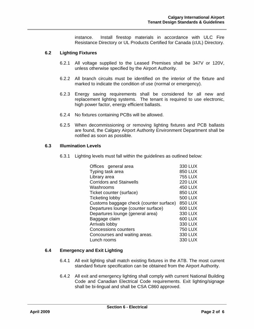
Calgary International Airport Tenant Design Standards & Guidelines
Section 6 - Electrical
April 2009 Page 2 of 6
instance. Install firestop materials in accordance with ULC Fire Resistance Directory or UL Products Certified for Canada (cUL) Directory.
6.2 Lighting Fixtures
6.2.1 All voltage supplied to the Leased Premises shall be 347V or 120V, unless otherwise specified by the Airport Authority.
6.2.2 All branch circuits must be identified on the interior of the fixture and marked to indicate the condition of use (normal or emergency).
6.2.3 Energy saving requirements shall be considered for all new and replacement lighting systems. The tenant is required to use electronic, high power factor, energy efficient ballasts.
6.2.4 No fixtures containing PCBs will be allowed.
6.2.5 When decommissioning or removing lighting fixtures and PCB ballasts are found, the Calgary Airport Authority Environment Department shall be notified as soon as possible.
6.3 Illumination Levels
6.3.1 Lighting levels must fall within the guidelines as outlined below:
Offices general area 330 LUX Typing task area 850 LUX Library area 755 LUX Corridors and Stairwells 220 LUX Washrooms 450 LUX Ticket counter (surface) 850 LUX Ticketing lobby 500 LUX Customs baggage check (counter surface) 850 LUX Departures lounge (counter surface) 600 LUX Departures lounge (general area) 330 LUX Baggage claim 600 LUX Arrivals lobby 330 LUX Concessions counters 750 LUX Concourses and waiting areas. 330 LUX Lunch rooms 330 LUX
6.4 Emergency and Exit Lighting
6.4.1 All exit lighting shall match existing fixtures in the ATB. The most current standard fixture specification can be obtained from the Airport Authority.
6.4.2 All exit and emergency lighting shall comply with current National Building Code and Canadian Electrical Code requirements. Exit lighting/signage shall be bi-lingual and shall be CSA C860 approved.
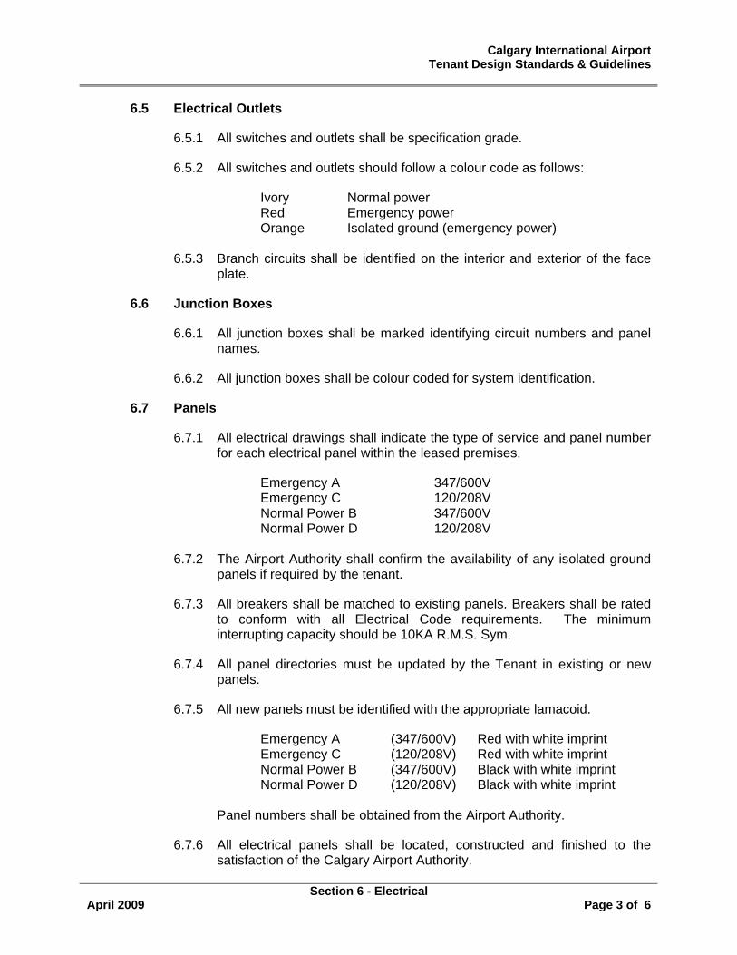
Calgary International Airport Tenant Design Standards & Guidelines
Section 6 - Electrical
April 2009 Page 3 of 6
6.5 Electrical Outlets
6.5.1 All switches and outlets shall be specification grade.
6.5.2 All switches and outlets should follow a colour code as follows:
Ivory Normal power Red Emergency power Orange Isolated ground (emergency power)
6.5.3 Branch circuits shall be identified on the interior and exterior of the face plate.
6.6 Junction Boxes
6.6.1 All junction boxes shall be marked identifying circuit numbers and panel names.
6.6.2 All junction boxes shall be colour coded for system identification.
6.7 Panels
6.7.1 All electrical drawings shall indicate the type of service and panel number for each electrical panel within the leased premises.
Emergency A 347/600V Emergency C 120/208V Normal Power B 347/600V Normal Power D 120/208V
6.7.2 The Airport Authority shall confirm the availability of any isolated ground panels if required by the tenant.
6.7.3 All breakers shall be matched to existing panels. Breakers shall be rated to conform with all Electrical Code requirements. The minimum interrupting capacity should be 10KA R.M.S. Sym.
6.7.4 All panel directories must be updated by the Tenant in existing or new panels.
6.7.5 All new panels must be identified with the appropriate lamacoid.
Emergency A (347/600V) Red with white imprint Emergency C (120/208V) Red with white imprint Normal Power B (347/600V) Black with white imprint Normal Power D (120/208V) Black with white imprint
Panel numbers shall be obtained from the Airport Authority.
6.7.6 All electrical panels shall be located, constructed and finished to the satisfaction of the Calgary Airport Authority.
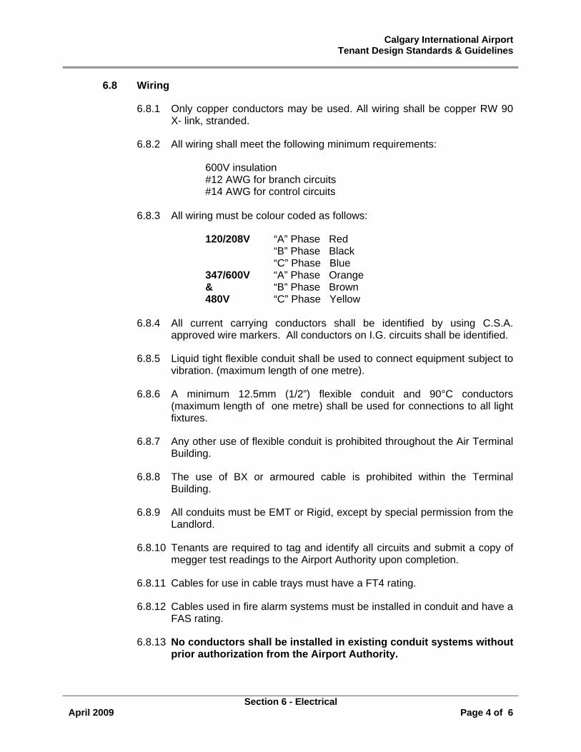
Calgary International Airport Tenant Design Standards & Guidelines
Section 6 - Electrical
April 2009 Page 4 of 6
6.8 Wiring
6.8.1 Only copper conductors may be used. All wiring shall be copper RW 90 X- link, stranded.
6.8.2 All wiring shall meet the following minimum requirements:
600V insulation #12 AWG for branch circuits #14 AWG for control circuits
6.8.3 All wiring must be colour coded as follows:
120/208V “A” Phase Red “B” Phase Black “C” Phase Blue 347/600V “A” Phase Orange & “B” Phase Brown 480V “C” Phase Yellow
6.8.4 All current carrying conductors shall be identified by using C.S.A. approved wire markers. All conductors on I.G. circuits shall be identified.
6.8.5 Liquid tight flexible conduit shall be used to connect equipment subject to vibration. (maximum length of one metre).
6.8.6 A minimum 12.5mm (1/2”) flexible conduit and 90°C conductors (maximum length of one metre) shall be used for connections to all light fixtures.
6.8.7 Any other use of flexible conduit is prohibited throughout the Air Terminal Building.
6.8.8 The use of BX or armoured cable is prohibited within the Terminal Building.
6.8.9 All conduits must be EMT or Rigid, except by special permission from the Landlord.
6.8.10 Tenants are required to tag and identify all circuits and submit a copy of megger test readings to the Airport Authority upon completion.
6.8.11 Cables for use in cable trays must have a FT4 rating.
6.8.12 Cables used in fire alarm systems must be installed in conduit and have a FAS rating.
6.8.13 No conductors shall be installed in existing conduit systems without prior authorization from the Airport Authority.
Calgary International Airport Tenant Design Standards & Guidelines
Section 6 - Electrical
April 2009 Page 5 of 6
6.8.14 All E.M.T. connectors and couplings must be rain tight or steel set screw type. The use of cast metal type will not be permitted.
6.8.15 As built drawings showing new conduits, cable runs, receptacles, panels, lights, circuit numbers, etc. are to be provided to the Calgary Airport Authority by the tenant’s contractor.
6.8.16 Conduits should not be run on the same support system as the communication tray.
6.8.17 Panel indexes shall be updated and submitted to the Calgary Airport Authority Electrical Coordinator.
6.9 Fire Alarm
6.9.1 The Calgary Airport Authority has supplied conduit to each retail space. The Landlord contractor will tie-in the Tenant’s fire alarm system to the base building system upon approval of the Tenant’s requirements and at the tenant’s expense.
6.9.2 All of the tenant’s in-store fire alarm components shall match the base building systems (Simplex).
6.9.3 All alterations and installations are to be done by certified personnel, verified by an independent engineer, and approved by Labour Canada.
6.9.4 The verification procedure shall comply with the requirements of CSA CAN S537.
6.9.5 The fire alarm CCT’s must be checked by Simplex after modifications or changes have been made.
6.9.6 Where required by Code, additional fire detection devices shall be installed at the Tenant’s expense.
6.10 Thermostats
6.10.1 The Calgary Airport Authority has installed one (1) thermostat in each retail space at a designated location indicated on the Base Building Drawing (see item 1.6).
6.10.2 It is the Tenant’s responsibility to determine the number and location(s) of thermostats required in his space. The Tenant at the Tenant’s expense shall undertake any additions or relocations required.
6.11 Inspections and Permits
6.11.1 The Tenant’s contractor is responsible for obtaining all necessary permits and approvals from the authorities having jurisdiction.
Calgary International Airport Tenant Design Standards & Guidelines
Section 6 - Electrical
April 2009 Page 6 of 6
6.11.2 The Tenant’s contractor is responsible for arranging and scheduling all necessary inspections by the authorities having jurisdiction.
6.11.3 The Calgary Airport Authority Electrical Coordinator shall inspect all electrical work prior to such work being enclosed within walls, floors and/or ceilings.
6.12 Demolition and Removal
6.12.1 Any utilities and services which are no longer required by the Tenant - or are to be abandoned - must be removed from the Leased Premises. Removal shall extend to the last junction box, sub-panel, or panel as the case may be.
6.12.2 All panel knock-outs shall be plugged with appropriate plugs, and all breaker locations shall be filled with appropriate blanks.
6.12.3 All panel directories and junction box labels shall be updated.
6.12.4 All abandoned circuits shall be recorded on a set of record drawings. Such drawings shall be submitted to the Airport Authority.
Calgary International Airport Tenant Design Standards & Guidelines
Section 7 - Communication
April 2009 Page 1 of 1
7.0 COMMUNICATION STANDARDS
The Calgary Airport Authority has completed the installation of a Fibre Optic Network throughout the ATB and to various parts of the airfield.
This fibre network will be used by both the Calgary Airport Authority and the Tenants as required. The documentation as set out in Appendix D highlights the requirements for communication and cabling installation. The Calgary Airport Authority has implemented a NORDX/CDT Standard and requires tenants to take this into account when implementing systems within the airport.
Any questions regarding this document or standards should be forwarded to the Airport Development Coordinator and/or Telecommunications Manager.
Appendix G
Air Terminal Building Communication Systems and Cabling Policy, Procedures and Standards.
Appendix H
Cable Management Information Requirements (Contractor Data Collection Process)
Calgary International Airport Tenant Design Standards & Guidelines
Section 8 – Other Areas
April 2009 Page 1 of 3
8.0 OTHER AREAS
8.1 Rental Car Centre / Parkade
All ATB standards apply within the Rental Car Centre and the Parkade.
8.1.1 Vehicle Rental Buildings - Drawings attached as Appendix ‘I’.
Where space is available, support buildings for vehicle rental agencies are to be located on the third level of the Parkade. Only one building will be allowed per car rental agency.
Vehicle Rental Buildings shall - at a maximum - take up the equivalent of two parking spaces. Unless otherwise approved by the Airport Authority, the following dimensions shall apply to all vehicle rental buildings:
Width: 4000mm (13’-0”)
Depth: 3800mm (12’-6”)
Height: 3000mm (10’-0”)
Dimensions are inclusive of curbing, steps, and ramps located outside of the building's exterior walls.
Protective curbing must be provided for all exposed walls. Such curbing shall be in the form of a poured-in-place concrete curb, or pre-cast concrete parking bumpers.
Entrances to vehicle rental buildings should be positioned so as to avoid conflict with vehicles and pedestrians.
Buildings should only be constructed of fire resistant materials. Wood frame construction is strictly prohibited. Wood may only be used for interior casework or millwork.
Exterior finishes are restricted to clear anodized aluminum siding.
Window glazing should be clear and sealed in clear anodized aluminum frames, equal to Kawneer Insuline 500 series.
Exterior doors should be sealed and glazed in clear anodized aluminum frames equal to Kawneer 190 narrow stile series.
Exterior lighting is limited to the illumination of access routes or for safety purposes. Decorative lighting will not be permitted.
Exterior signage is limited to one (1) fascia identification sign per elevation. Signage is restricted to a 500mm high sign band set at 2500mm to 3000mm above the Parkade floor slab. The maximum
Calgary International Airport Tenant Design Standards & Guidelines
Section 8 – Other Areas
April 2009 Page 2 of 3
lettering height is restricted to 400mm. Exterior signage is restricted to backlit illumination only and should conform to CSA requirements.
All parking stall identification signs are limited to 400mm x 400mm in size unless otherwise approved by the Airport Authority. The top of all signs must be set at 1800mm above the curb.
At the Airport Authority’s discretion, car rental agency identification signs may be allowed on the pre-cast concrete ceiling tee joists within the Parkade. These signs should be mounted using small amounts of adhesive. The tenant is responsible for the removal of all mounting adhesive if the signage is relocated or removed. No holes shall be drilled into the structural ceiling tee joists due to the existence of pre-stressed cables.
Alternative methods for providing parking stall identification signage and/or car rental identification signage may be considered by the Airport Authority, but specific approval will be required.
Electrical power is available in the form of 120/208, 3 phase. The tenant shall be responsible for all connections, conduit, and wiring to the building site. Heating, if required, shall be electrically generated. Water and sewer services are not available.
(a) Sign Guidelines
All interior and exterior sign proposals must be approved by the Development Coordinator, prior to installation.
8.2 Airport Terminal Reserve
8.2.1 Ancillary Buildings
Tenants proposing to install buildings within the Terminal Campus must receive approval from the Development Coordinator.
Temporary buildings must be constructed and finished in a high quality and should compliment the colors and finishes of the surrounding buildings. The Airport Authority will discourage the use of temporary sheds and trailers.
Both temporary and permanent buildings require approval/permits from the City of Calgary. Such approvals can only be obtained with the written permission of the Calgary Airport Authority. See item 1.2.
8.3 Airport Corporate Centre
Although the standards laid out in this document do not apply to the Airport Corporate Centre, tenants in this building still require a Construction & Installation Permit (CIP) from the Airport Authority. See item 1.2.
Calgary International Airport Tenant Design Standards & Guidelines
Section 8 – Other Areas
April 2009 Page 3 of 3
Prior to obtaining a Building Permit from the City of Calgary, the tenant is required to obtain a letter of approval from the Development Coordinator.
The tenant is required to obtain development and construction approval from Dundee Realty Management Corporation prior to submitting an application to the City of Calgary and the Airport Authority.
Contact Info:
Ms. Michele Westeen Property Manager Dundee Realty Management Corporation 1167 Kensington Crescent NW, Suite 250 Calgary, Alberta T2N 1X7 403.270.4674 (phone) 403.212.7179 (fax) [email protected]
Calgary International Airport Tenant Design Standards & Guidelines
Section 9 – Final Inspection
April 2009 Page 1 of 1
9.0 PROJECT COMPLETION
9.1 Final Inspection and Acceptance of the Work
The Tenant shall notify the Tenant’s Consultant(s) and The Calgary Airport Authority (Airport Authority) in writing when all deficiencies are complete and final clean up has been done. The Tenant and his Consultant(s) along with the Airport Authority will make a final inspection to ascertain if the Work has been fully completed in accordance with the Approved Detail Drawings.
9.2 Occupancy Permit
The Tenant is responsible for obtaining an Occupancy Permit from the City of Calgary prior to commencing operations. Proof of obtaining the Occupancy Permit must be submitted to the Airport Authority prior to commencing operations.
9.3 Statutory Declaration
A Statutory Declaration is a legal form completed by the Tenant’s contractor(s) and witnessed by a Commissioner of Oaths, Notary Public or Justice of the Peace at the end of the construction period stating to the Owner, in this case the Tenant, that he has discharged all his lawful obligations with respect to the performance of the Contract, including without limitation, payment of all accounts for labour, subcontractors, suppliers, debts arising out of statutory requirements, and other indebtedness which may have been incurred by him, up to the date specified.
At the Airport Authority’s request, the Tenant should submit to the Airport Authority, its Contractor’s Statutory Declaration as required under the Construction Schedule. The Tenant will also furnish evidence of compliance with the requirements of the Workers’ Compensation Act as required under the Construction Schedule.
9.4 As-Builts
At the end of the construction period and within the time period specified by the Lease, the Tenant must provide the Airport Authority with one (1) set of good quality reproducible prints of all drawings and one set electronic files as specified by the Development Coordinator, documenting all as-built conditions. If the required documentation is not received by the Airport Authority within the specified time period, the Airport Authority will undertake the work at the Tenant’s expense.
Appendix “A” Construction Installation Permit
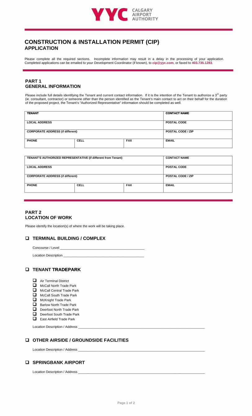
TENANT TENANT CONTACT NAME CONTACT NAME
LOCAL ADDRESS POSTAL CODE
CORPORATE ADDRESS (if different) POSTAL CODE / ZIP
PHONE CELL FAX EMAIL
TENANT’S AUTHORIZED REPRESENTATIVE (if different from Tenant) CONTACT NAME
LOCAL ADDRESS POSTAL CODE
CORPORATE ADDRESS (if different) POSTAL CODE / ZIP
PHONE CELL FAX EMAIL
Please include full details identifying the Tenant and current contact information. If it is the intention of the Tenant to authorize a 3rd party (ie. consultant, contractor) or someone other than the person identified as the Tenant’s main contact to act on their behalf for the duration of the proposed project, the Tenant’s “Authorized Representative” information should be completed as well.
PART 1 GENERAL INFORMATION
Please complete all the required sections. Incomplete information may result in a delay in the processing of your application. Completed applications can be emailed to your Development Coordinator (if known), to [email protected], or faxed to 403.735.1283.
CONSTRUCTION & INSTALLATION PERMIT (CIP) APPLICATION
Page 1 of 2
TERMINAL BUILDING / COMPLEX
Concourse / Level ______________________________________________ Location Description ____________________________________________
Please identify the location(s) of where the work will be taking place.
PART 2 LOCATION OF WORK
TENANT TRADEPARK TRADEPARK
Air Terminal District McCall North Trade Park McCall Central Trade Park McCall South Trade Park McKnight Trade Park Barlow North Trade Park Deerfoot North Trade Park Deerfoot South Trade Park East Airfield Trade Park
Location Description / Address _____________________________________________________________________
OTHER AIRSIDE / GROUNDSIDE FACILITIES
Location Description / Address _____________________________________________________________________
SPRINGBANK AIRPORT
Location Description / Address _____________________________________________________________________
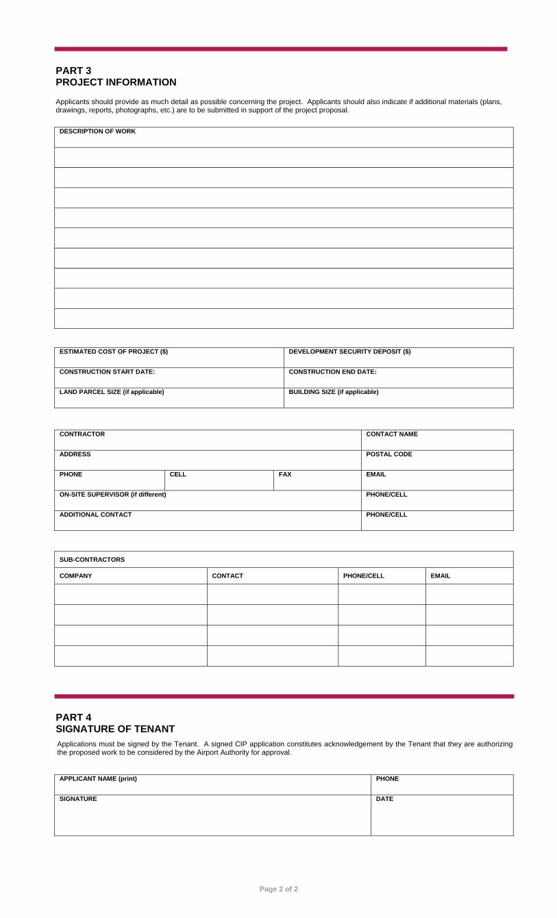
DESCRIPTION OF WORK
ESTIMATED COST OF PROJECT ($) DEVELOPMENT SECURITY DEPOSIT ($)
CONSTRUCTION START DATE: CONSTRUCTION END DATE:
LAND PARCEL SIZE (if applicable) BUILDING SIZE (if applicable)
CONTRACTOR CONTACT NAME
ADDRESS POSTAL CODE
PHONE CELL FAX EMAIL
ON-SITE SUPERVISOR (if different) PHONE/CELL
ADDITIONAL CONTACT PHONE/CELL
SUB-CONTRACTORS
COMPANY CONTACT PHONE/CELL EMAIL
APPLICANT NAME (print) PHONE
SIGNATURE DATE
PART 3 PROJECT INFORMATION
Applicants should provide as much detail as possible concerning the project. Applicants should also indicate if additional materials (plans, drawings, reports, photographs, etc.) are to be submitted in support of the project proposal.
PART 4 SIGNATURE OF TENANT Applications must be signed by the Tenant. A signed CIP application constitutes acknowledgement by the Tenant that they are authorizing the proposed work to be considered by the Airport Authority for approval.
Page 2 of 2
Appendix “B” Building Services Shut-Down Request
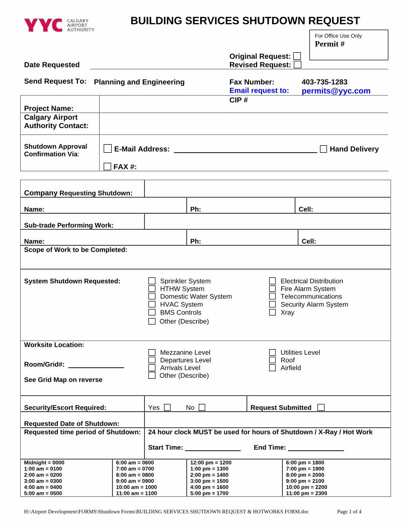
BUILDING SERVICES SHUTDOWN REQUEST
For Office Use Only Permit #
Date Requested
Original Request: Revised Request:
Send Request To:
Planning and Engineering
Fax Number:
403-735-1283
Email request to: [email protected] Project Name:
CIP #
Calgary Airport Authority Contact:
Shutdown Approval Confirmation Via:
E-Mail Address: Hand Delivery
FAX #:
Company Requesting Shutdown:
Name: Ph: Cell:
Sub-trade Performing Work:
Name: Ph: Cell: Scope of Work to be Completed:
System Shutdown Requested: Sprinkler System Electrical Distribution HTHW System Fire Alarm System
Domestic Water System Telecommunications HVAC System Security Alarm System BMS Controls Xray
Other (Describe)
Worksite Location: Mezzanine Level Utilities Level Departures Level Roof Arrivals Level Airfield Room/Grid#:
See Grid Map on reverse Other (Describe)
Security/Escort Required:
Yes No
Request Submitted
Requested Date of Shutdown:
Requested time period of Shutdown: 24 hour clock MUST be used for hours of Shutdown / X-Ray / Hot Work Start Time: End Time:
Midnight = 0000 1:00 am = 0100 2:00 am = 0200 3:00 am = 0300 4:00 am = 0400 5:00 am = 0500
6:00 am = 0600 7:00 am = 0700 8:00 am = 0800 9:00 am = 0900 10:00 am = 1000 11:00 am = 1100
12:00 pm = 1200 1:00 pm = 1300 2:00 pm = 1400 3:00 pm = 1500 4:00 pm = 1600 5:00 pm = 1700
6:00 pm = 1800 7:00 pm = 1900 8:00 pm = 2000 9:00 pm = 2100 10:00 pm = 2200 11:00 pm = 2300
H:\Airport Development\FORMS\Shutdown Forms\BUILDING SERVICES SHUTDOWN REQUEST & HOTWORKS FORM.doc Page 1 of 4
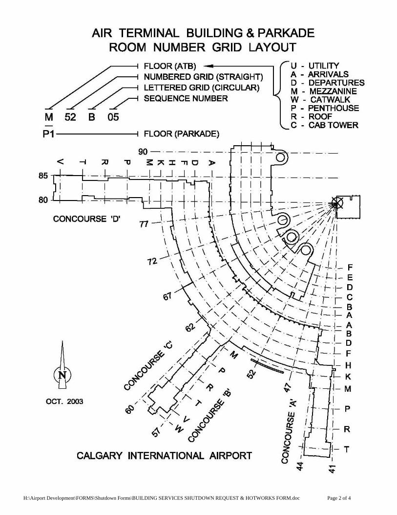
H:\Airport Development\FORMS\Shutdown Forms\BUILDING SERVICES SHUTDOWN REQUEST & HOTWORKS FORM.doc Page 2 of 4

BUILDING SERVICES SHUTDOWN REQUEST
For Office Use Only Permit #
Date Requested
DATE SUBMITTED Original Request: Revised Request:
Send Request To:
Planning and Engineering
Fax Number:
403-735-1283
Email request to: [email protected] Project Name:
Name # if known Please use above address to submit by email
Calgary Airport Authority Contact:
Name of the Calgary Airport Authority Contact or Project Manager Name
Shutdown Approval Confirmation Via:
Email address is preferred. Please indicate a Current email address E-Mail Address: Hand Delivery
FAX #:
Company Requesting Shutdown:
The full name of the company submitting the shutdown
Name: Name of contact person Ph: Mandatory Cell: Mandatory
Sub-trade Performing Work: Name of company completing the Work if sub-trade is being used.
Name: Sub trade contractor Name of company Ph: sub contractor’s phone # Cell: Sub Contractor Cell Scope of Work to be Completed: Complete description of work being performed. NOTE: IF the following Welding/cutting/grinding/soldering is being performed, please complete HOT WORKS PERMIT
System Shutdown Requested: Sprinkler System Electrical Distribution Please check off the areas effected HTHW System Fire Alarm System
Domestic Water System Telecommunications HVAC System Security Alarm System BMS Controls XRAY
Please indicate a system that is being shutdown and full description
Other (Describe)
Worksite Location: Mezzanine Level Utilities Level Departures Level Roof Arrivals Level Airfield Room/Grid#:
See Grid Map on page 2 – please mark the location Other (Describe)
Please indicate full location if this is Airside/Airfield
Please check off Security/Escort Required:
Yes No
Request Submitted
Requested Date of Shutdown:
Please complete Dates of shutdown
Requested time period of Shutdown: Please use 24 hrs clock
24 hour clock MUST be used for hours of Shutdown / X-Ray / Hotwork See chart listed below Start date: End date:
Midnight = 0000 1:00 am = 0100 2:00 am = 0200 3:00 am = 0300 4:00 am = 0400 5:00 am = 0500
6:00 am = 0600 7:00 am = 0700 8:00 am = 0800 9:00 am = 0900 10:00 am = 1000 11:00 am = 1100
12:00 pm = 1200 1:00 pm = 1300 2:00 pm = 1400 3:00 pm = 1500 4:00 pm = 1600 5:00 pm = 1700
6:00 pm = 1800 7:00 pm = 1900 8:00 pm = 2000 9:00 pm = 2100 10:00 pm = 2200 11:00 pm = 2300
H:\Airport Development\FORMS\Shutdown Forms\Filling out Shutdown form.doc Page 1 of 2
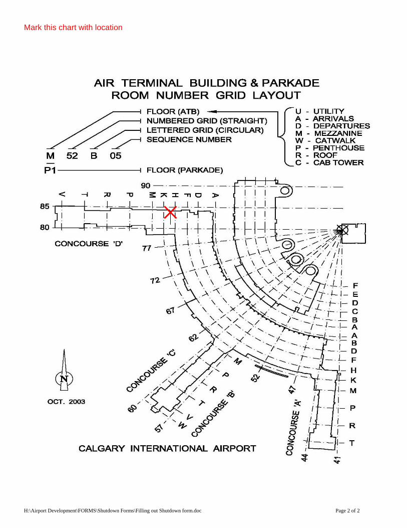
Mark this chart with location
H:\Airport Development\FORMS\Shutdown Forms\Filling out Shutdown form.doc Page 2 of 2
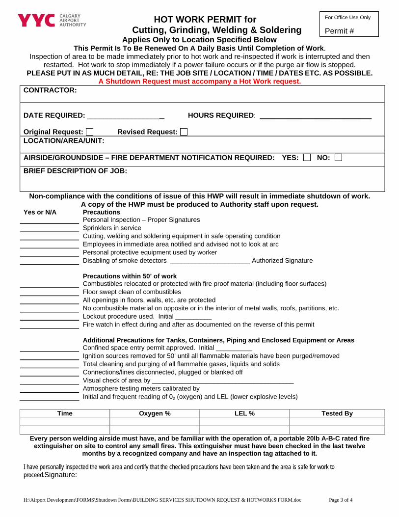
HOT WORK PERMIT for For Office Use Only Permit #Cutting, Grinding, Welding & Soldering
Applies Only to Location Specified Below This Permit Is To Be Renewed On A Daily Basis Until Completion of Work.
Inspection of area to be made immediately prior to hot work and re-inspected if work is interrupted and then restarted. Hot work to stop immediately if a power failure occurs or if the purge air flow is stopped.
PLEASE PUT IN AS MUCH DETAIL, RE: THE JOB SITE / LOCATION / TIME / DATES ETC. AS POSSIBLE. A Shutdown Request must accompany a Hot Work request.
CONTRACTOR: DATE REQUIRED: __________________ HOURS REQUIRED: ____________________________ Original Request: Revised Request: LOCATION/AREA/UNIT: AIRSIDE/GROUNDSIDE – FIRE DEPARTMENT NOTIFICATION REQUIRED: YES: NO:
BRIEF DESCRIPTION OF JOB:
Non-compliance with the conditions of issue of this HWP will result in immediate shutdown of work. A copy of the HWP must be produced to Authority staff upon request.
Yes or N/A Precautions Personal Inspection – Proper Signatures Sprinklers in service Cutting, welding and soldering equipment in safe operating condition Employees in immediate area notified and advised not to look at arc Personal protective equipment used by worker Disabling of smoke detectors ______________________ Authorized Signature Precautions within 50’ of work Combustibles relocated or protected with fire proof material (including floor surfaces) Floor swept clean of combustibles All openings in floors, walls, etc. are protected No combustible material on opposite or in the interior of metal walls, roofs, partitions, etc. Lockout procedure used. Initial __________ Fire watch in effect during and after as documented on the reverse of this permit Additional Precautions for Tanks, Containers, Piping and Enclosed Equipment or Areas Confined space entry permit approved. Initial __________ Ignition sources removed for 50’ until all flammable materials have been purged/removed Total cleaning and purging of all flammable gases, liquids and solids Connections/lines disconnected, plugged or blanked off Visual check of area by _______________________________________ Atmosphere testing meters calibrated by Initial and frequent reading of 02 (oxygen) and LEL (lower explosive levels)
Time Oxygen % LEL % Tested By
Every person welding airside must have, and be familiar with the operation of, a portable 20lb A-B-C rated fire extinguisher on site to control any small fires. This extinguisher must have been checked in the last twelve
months by a recognized company and have an inspection tag attached to it.
I have personally inspected the work area and certify that the checked precautions have been taken and the area is safe for work to proceed.Signature:
H:\Airport Development\FORMS\Shutdown Forms\BUILDING SERVICES SHUTDOWN REQUEST & HOTWORKS FORM.doc Page 3 of 4
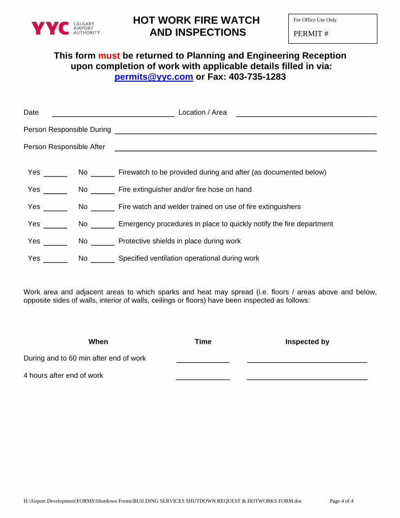
For Office Use Only
PERMIT #
For Office Use Only
PERMIT # HOT WORK FIRE WATCH
AND INSPECTIONS
This form must be returned to Planning and Engineering Reception upon completion of work with applicable details filled in via:
[email protected] or Fax: 403-735-1283
Date
Location / Area
Person Responsible During
Person Responsible After
Yes
No
Firewatch to be provided during and after (as documented below)
Yes
No
Fire extinguisher and/or fire hose on hand
Yes
No
Fire watch and welder trained on use of fire extinguishers
Yes
No
Emergency procedures in place to quickly notify the fire department
Yes
No
Protective shields in place during work
Yes
No
Specified ventilation operational during work Work area and adjacent areas to which sparks and heat may spread (i.e. floors / areas above and below, opposite sides of walls, interior of walls, ceilings or floors) have been inspected as follows:
When Time Inspected by
During and to 60 min after end of work
4 hours after end of work
H:\Airport Development\FORMS\Shutdown Forms\BUILDING SERVICES SHUTDOWN REQUEST & HOTWORKS FORM.doc Page 4 of 4
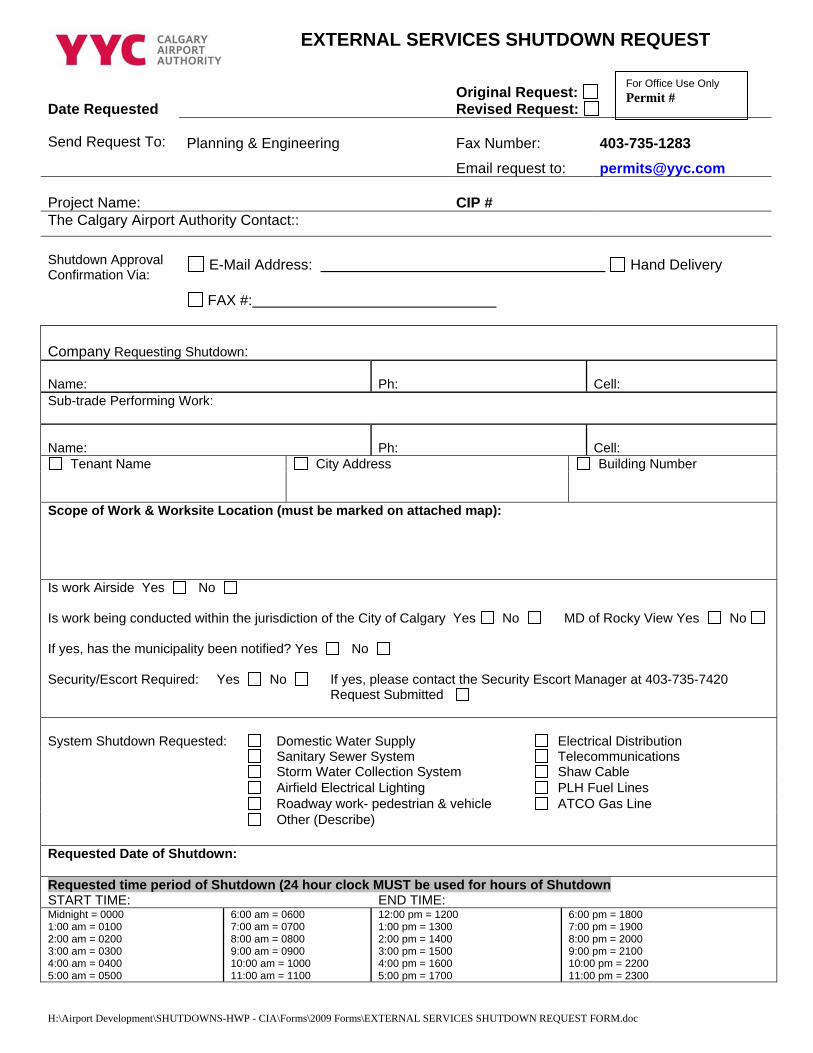
H:\Airport Development\SHUTDOWNS-HWP - CIA\Forms\2009 Forms\EXTERNAL SERVICES SHUTDOWN REQUEST FORM.doc
For Office Use Only Permit #
EXTERNAL SERVICES SHUTDOWN REQUEST
Date Requested
Original Request: Revised Request:
Send Request To:
Planning & Engineering
Fax Number:
403-735-1283
Email request to: [email protected] Project Name:
CIP #
The Calgary Airport Authority Contact:: Shutdown Approval Confirmation Via:
E-Mail Address: Hand Delivery
FAX #:
Company Requesting Shutdown: Name: Ph: Cell: Sub-trade Performing Work: Name: Ph: Cell:
Tenant Name City Address Building Number Scope of Work & Worksite Location (must be marked on attached map): Is work Airside Yes No Is work being conducted within the jurisdiction of the City of Calgary Yes No MD of Rocky View Yes No If yes, has the municipality been notified? Yes No Security/Escort Required:
Yes No
If yes, please contact the Security Escort Manager at 403-735-7420 Request Submitted
System Shutdown Requested:
Domestic Water Supply
Electrical Distribution
Sanitary Sewer System Telecommunications Storm Water Collection System Shaw Cable Airfield Electrical Lighting PLH Fuel Lines Roadway work- pedestrian & vehicle ATCO Gas Line
Other (Describe)
Requested Date of Shutdown: Requested time period of Shutdown (24 hour clock MUST be used for hours of Shutdown START TIME: END TIME: Midnight = 0000 1:00 am = 0100 2:00 am = 0200 3:00 am = 0300 4:00 am = 0400 5:00 am = 0500
6:00 am = 0600 7:00 am = 0700 8:00 am = 0800 9:00 am = 0900 10:00 am = 1000 11:00 am = 1100
12:00 pm = 1200 1:00 pm = 1300 2:00 pm = 1400 3:00 pm = 1500 4:00 pm = 1600 5:00 pm = 1700
6:00 pm = 1800 7:00 pm = 1900 8:00 pm = 2000 9:00 pm = 2100 10:00 pm = 2200 11:00 pm = 2300
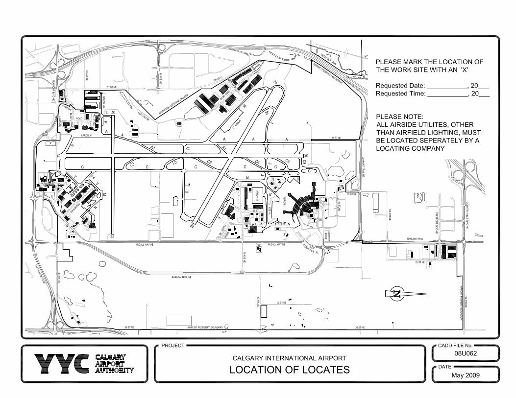


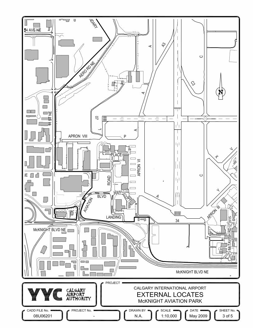


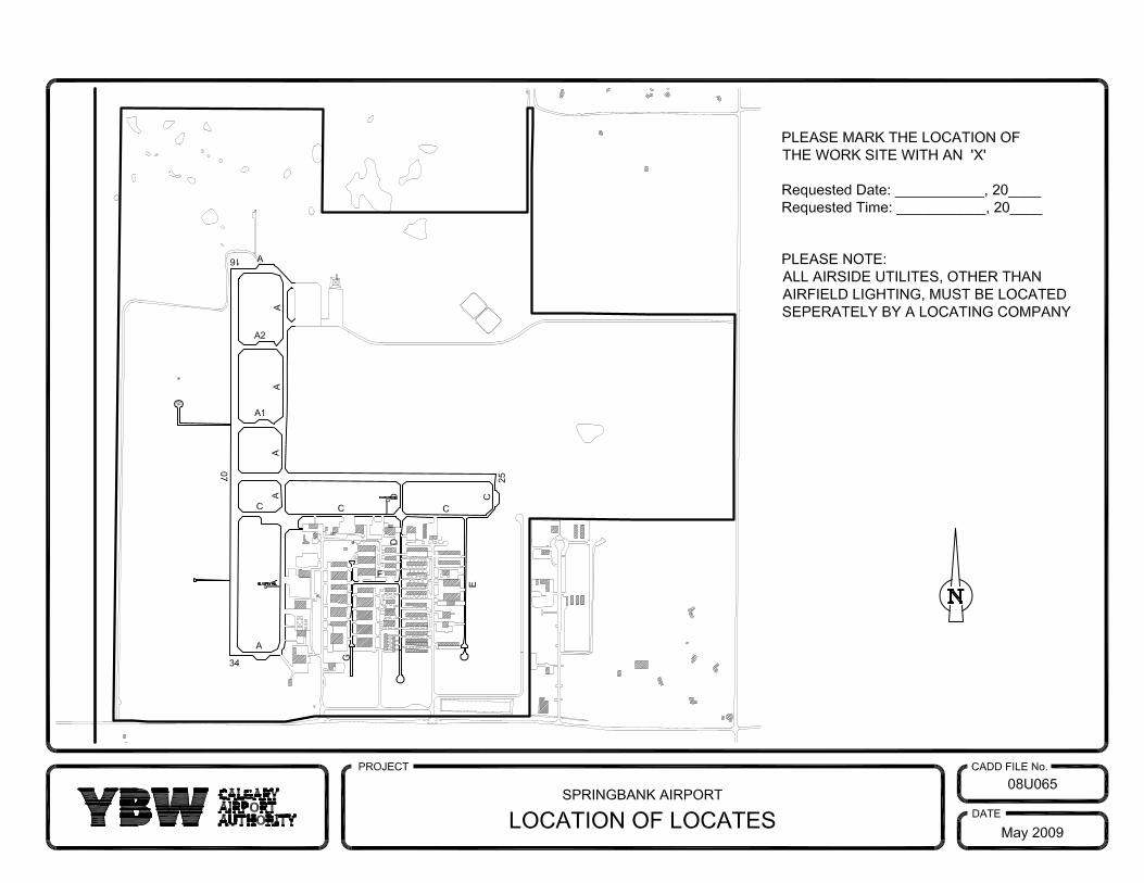
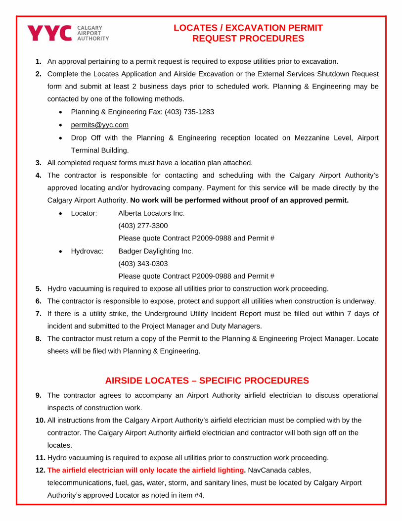
LOCATES / EXCAVATION PERMIT
REQUEST PROCEDURES
1. An approval pertaining to a permit request is required to expose utilities prior to excavation. 2. Complete the Locates Application and Airside Excavation or the External Services Shutdown Request
form and submit at least 2 business days prior to scheduled work. Planning & Engineering may be
contacted by one of the following methods.
• Planning & Engineering Fax: (403) 735-1283
• Drop Off with the Planning & Engineering reception located on Mezzanine Level, Airport
Terminal Building. 3. All completed request forms must have a location plan attached.
4. The contractor is responsible for contacting and scheduling with the Calgary Airport Authority’s
approved locating and/or hydrovacing company. Payment for this service will be made directly by the
Calgary Airport Authority. No work will be performed without proof of an approved permit.
• Locator: Alberta Locators Inc.
(403) 277-3300
Please quote Contract P2009-0988 and Permit #
• Hydrovac: Badger Daylighting Inc.
(403) 343-0303
Please quote Contract P2009-0988 and Permit #
5. Hydro vacuuming is required to expose all utilities prior to construction work proceeding.
6. The contractor is responsible to expose, protect and support all utilities when construction is underway.
7. If there is a utility strike, the Underground Utility Incident Report must be filled out within 7 days of
incident and submitted to the Project Manager and Duty Managers.
8. The contractor must return a copy of the Permit to the Planning & Engineering Project Manager. Locate
sheets will be filed with Planning & Engineering.
AIRSIDE LOCATES – SPECIFIC PROCEDURES
9. The contractor agrees to accompany an Airport Authority airfield electrician to discuss operational
inspects of construction work.
10. All instructions from the Calgary Airport Authority’s airfield electrician must be complied with by the
contractor. The Calgary Airport Authority airfield electrician and contractor will both sign off on the
locates.
11. Hydro vacuuming is required to expose all utilities prior to construction work proceeding.
12. The airfield electrician will only locate the airfield lighting. NavCanada cables,
telecommunications, fuel, gas, water, storm, and sanitary lines, must be located by Calgary Airport
Authority’s approved Locator as noted in item #4.
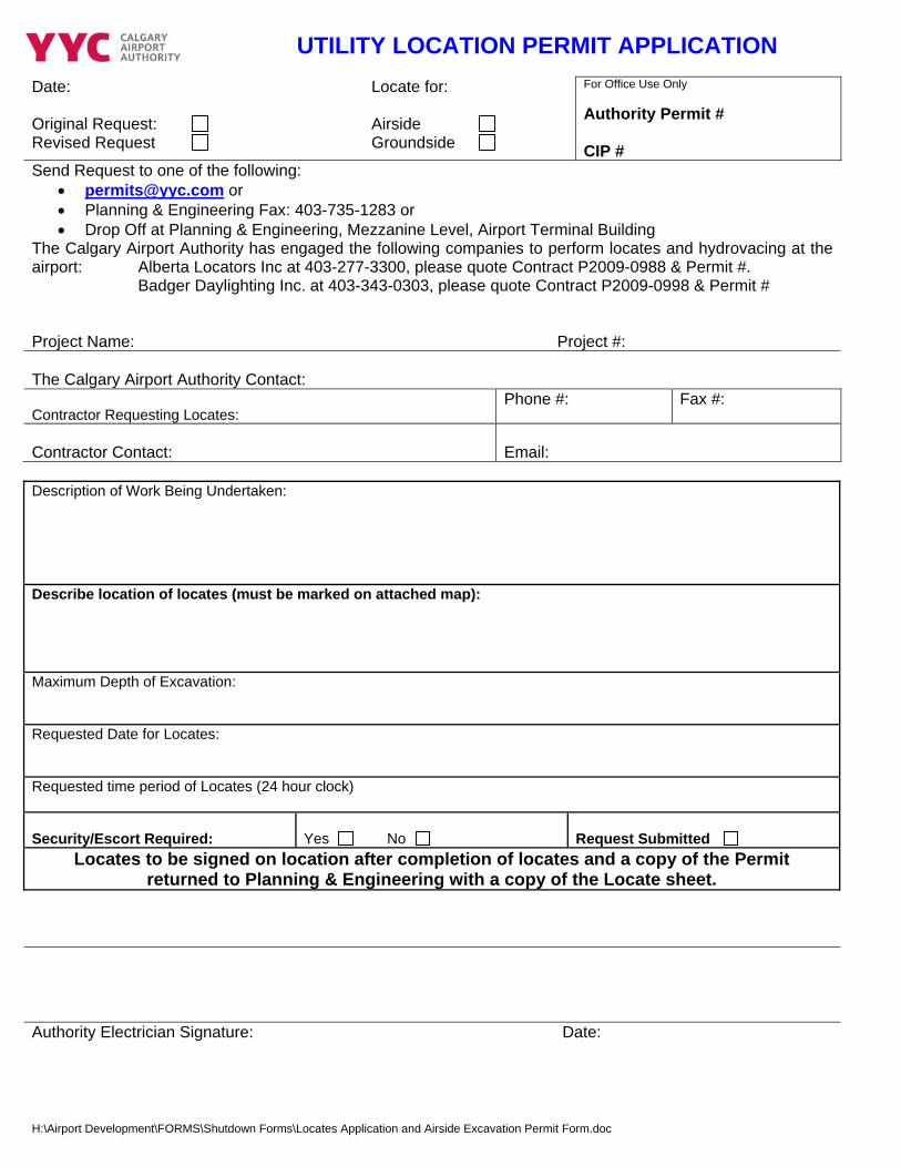
UTILITY LOCATION PERMIT APPLICATION
Date: Original Request: Revised Request
Locate for: Airside Groundside
For Office Use Only Authority Permit # CIP #
Send Request to one of the following: • [email protected] or • Planning & Engineering Fax: 403-735-1283 or • Drop Off at Planning & Engineering, Mezzanine Level, Airport Terminal Building
The Calgary Airport Authority has engaged the following companies to perform locates and hydrovacing at the airport: Alberta Locators Inc at 403-277-3300, please quote Contract P2009-0988 & Permit #. Badger Daylighting Inc. at 403-343-0303, please quote Contract P2009-0998 & Permit # Project Name:
Project #:
The Calgary Airport Authority Contact: Contractor Requesting Locates:
Phone #: Fax #:
Contractor Contact:
Email:
Description of Work Being Undertaken:
Describe location of locates (must be marked on attached map):
Maximum Depth of Excavation: Requested Date for Locates: Requested time period of Locates (24 hour clock) Security/Escort Required:
Yes No
Request Submitted
Locates to be signed on location after completion of locates and a copy of the Permit returned to Planning & Engineering with a copy of the Locate sheet.
Authority Electrician Signature: Date:
H:\Airport Development\FORMS\Shutdown Forms\Locates Application and Airside Excavation Permit Form.doc
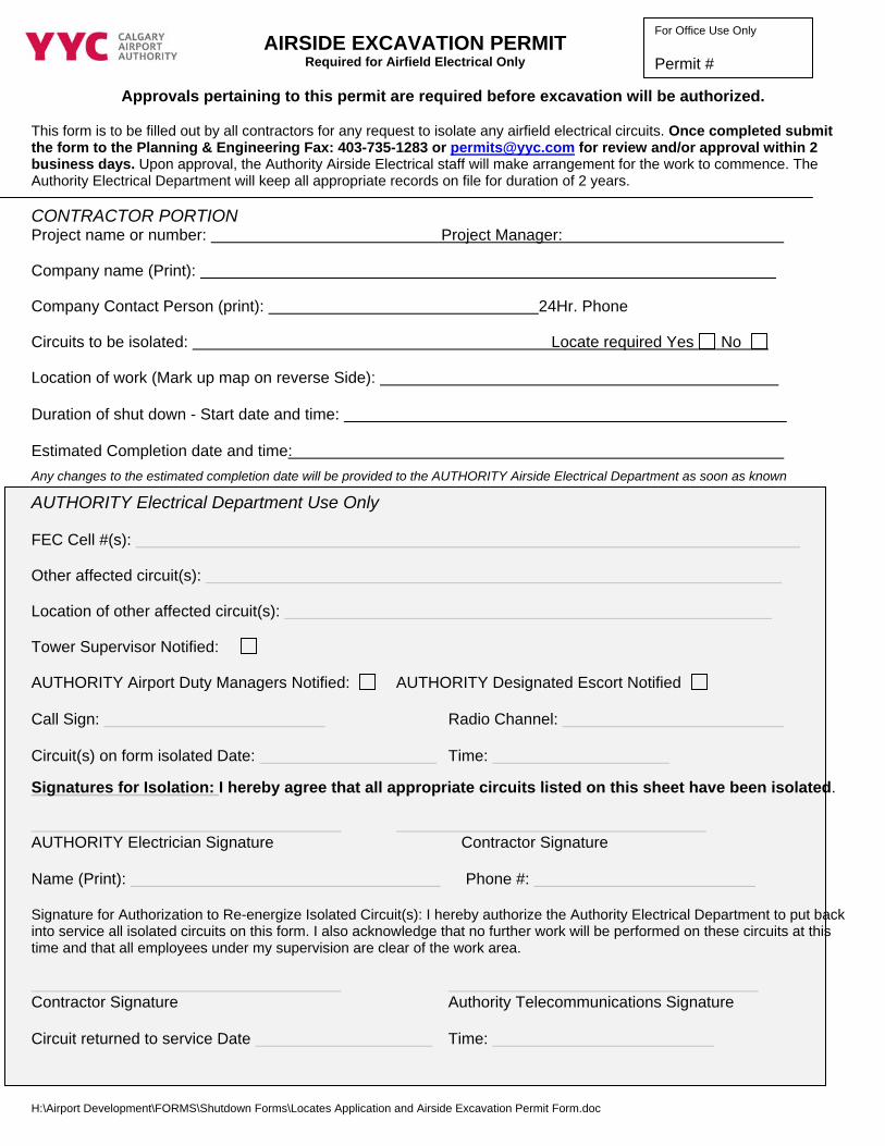
For Office Use Only
Permit #AIRSIDE EXCAVATION PERMIT
Required for Airfield Electrical Only
Approvals pertaining to this permit are required before excavation will be authorized.
This form is to be filled out by all contractors for any request to isolate any airfield electrical circuits. Once completed submit the form to the Planning & Engineering Fax: 403-735-1283 or [email protected] for review and/or approval within 2 business days. Upon approval, the Authority Airside Electrical staff will make arrangement for the work to commence. The Authority Electrical Department will keep all appropriate records on file for duration of 2 years. CONTRACTOR PORTION Project name or number: Project Manager:
Company name (Print):
Company Contact Person (print): 24Hr. Phone
Circuits to be isolated: Locate required Yes No
Location of work (Mark up map on reverse Side): Duration of shut down - Start date and time: Estimated Completion date and time: Any changes to the estimated completion date will be provided to the AUTHORITY Airside Electrical Department as soon as known
AUTHORITY Electrical Department Use Only FEC Cell #(s):
Other affected circuit(s):
Location of other affected circuit(s):
Tower Supervisor Notified:
AUTHORITY Airport Duty Managers Notified: AUTHORITY Designated Escort Notified Call Sign: Radio Channel: Circuit(s) on form isolated Date: Time: Signatures for Isolation: I hereby agree that all appropriate circuits listed on this sheet have been isolated. AUTHORITY Electrician Signature Contractor Signature Name (Print): Phone #: Signature for Authorization to Re-energize Isolated Circuit(s): I hereby authorize the Authority Electrical Department to put back into service all isolated circuits on this form. I also acknowledge that no further work will be performed on these circuits at this time and that all employees under my supervision are clear of the work area. Contractor Signature Authority Telecommunications Signature Circuit returned to service Date Time:
H:\Airport Development\FORMS\Shutdown Forms\Locates Application and Airside Excavation Permit Form.doc
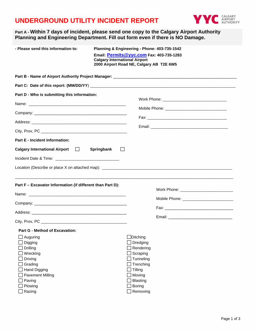
Page 1 of 3
UNDERGROUND UTILITY INCIDENT REPORT Part A - Within 7 days of incident, please send one copy to the Calgary Airport Authority Planning and Engineering Department. Fill out form even if there is NO Damage.
- Please send this information to: Planning & Engineering - Phone: 403-735-1542 Email: [email protected] Fax: 403-735-1283
Calgary International Airport 2000 Airport Road NE, Calgary AB T2E 6W5
Part B - Name of Airport Authority Project Manager: ________________________________________________________ Part C: Date of this report: (MM/DD/YY) __________________________________________________________________ Part D - Who is submitting this information: Name: ____________________________________________ Company: __________________________________________ Address: ___________________________________________ City, Prov, PC _______________________________________
Work Phone: _____________________________ Mobile Phone: ____________________________ Fax: ____________________________________ Email: ___________________________________
Part E - Incident Information: Calgary International Airport Springbank Incident Date & Time: _____________________________ Location (Describe or place X on attached map): ___________________________________________________________ ___________________________________________________________________________________________________ Part F – Excavator Information (if different than Part D): Name: ____________________________________________ Company: __________________________________________ Address: ___________________________________________ City, Prov, PC _______________________________________
Work Phone: ________________________ Mobile Phone: _______________________ Fax: _______________________________ Email: _____________________________
Part G - Method of Excavation:
Auguring Ditching Digging Dredging Drilling Rendering Wrecking Scraping Driving Tunneling Grading Trenching Hand Digging Tilling Pavement Milling Moving Paving Blasting Plowing Boring Razing Removing
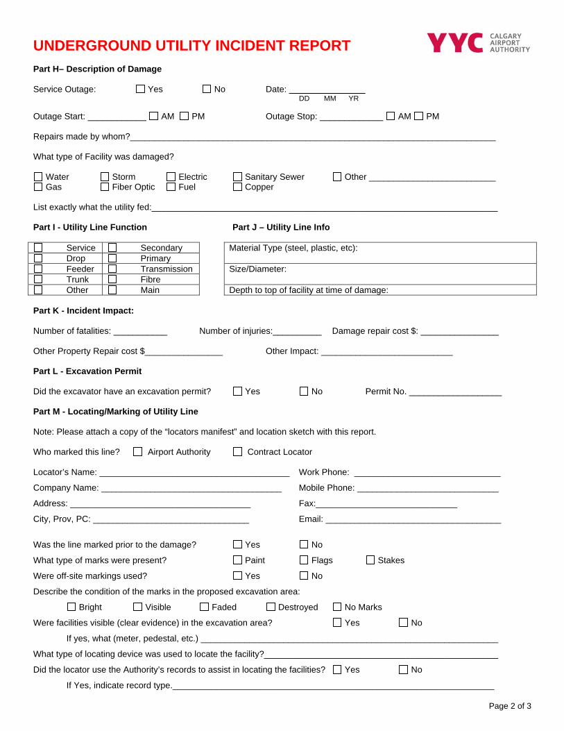
Page 2 of 3
UNDERGROUND UTILITY INCIDENT REPORT Part H– Description of Damage Service Outage: Yes No Date: DD MM YR Outage Start: ____________ AM PM Outage Stop: _____________ AM PM Repairs made by whom?___________________________________________________________________________ What type of Facility was damaged?
Water Storm Electric Sanitary Sewer Other __________________________ Gas Fiber Optic Fuel Copper
List exactly what the utility fed:_______________________________________________________________________ Part I - Utility Line Function Part J – Utility Line Info
Service Secondary Drop Primary
Material Type (steel, plastic, etc):
Feeder Transmission Trunk Fibre
Size/Diameter:
Other Main Depth to top of facility at time of damage: Part K - Incident Impact: Number of fatalities: ___________ Number of injuries:__________ Damage repair cost $: ________________ Other Property Repair cost $________________ Other Impact: ___________________________ Part L - Excavation Permit Did the excavator have an excavation permit? Yes No Permit No. ___________________ Part M - Locating/Marking of Utility Line Note: Please attach a copy of the “locators manifest” and location sketch with this report. Who marked this line? Airport Authority Contract Locator Locator’s Name: _______________________________________ Work Phone: ______________________________
Company Name: _____________________________________ Mobile Phone: _____________________________
Address: _____________________________________ Fax:_____________________________
City, Prov, PC: ________________________________ Email: ____________________________________
Was the line marked prior to the damage? Yes No
What type of marks were present? Paint Flags Stakes
Were off-site markings used? Yes No
Describe the condition of the marks in the proposed excavation area:
Bright Visible Faded Destroyed No Marks
Were facilities visible (clear evidence) in the excavation area? Yes No
If yes, what (meter, pedestal, etc.) _____________________________________________________________
What type of locating device was used to locate the facility?________________________________________________
Did the locator use the Authority’s records to assist in locating the facilities? Yes No
If Yes, indicate record type.__________________________________________________________________
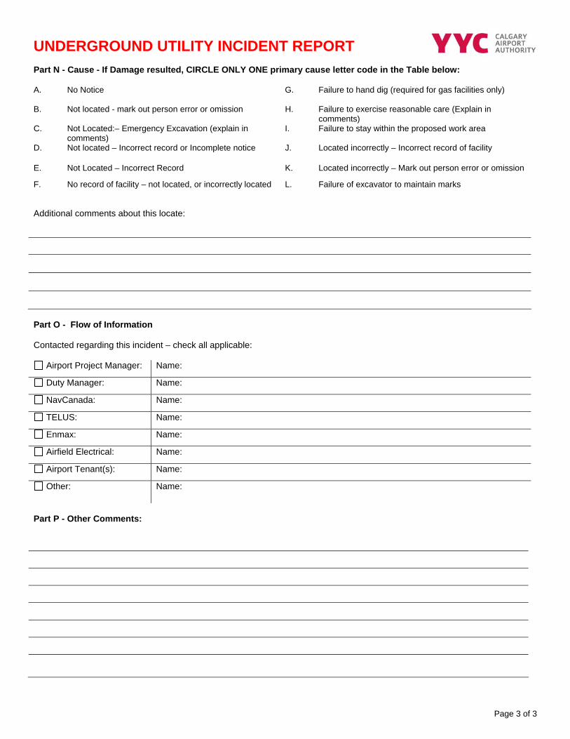
Page 3 of 3
UNDERGROUND UTILITY INCIDENT REPORT Part N - Cause - If Damage resulted, CIRCLE ONLY ONE primary cause letter code in the Table below: A. No Notice G. Failure to hand dig (required for gas facilities only)
B. Not located - mark out person error or omission H. Failure to exercise reasonable care (Explain in comments)
C. Not Located:– Emergency Excavation (explain in comments)
I. Failure to stay within the proposed work area
D. Not located – Incorrect record or Incomplete notice J. Located incorrectly – Incorrect record of facility
E. Not Located – Incorrect Record K. Located incorrectly – Mark out person error or omission
F. No record of facility – not located, or incorrectly located L. Failure of excavator to maintain marks
Additional comments about this locate:
Part O - Flow of Information Contacted regarding this incident – check all applicable:
Airport Project Manager: Name:
Duty Manager: Name:
NavCanada: Name:
TELUS: Name:
Enmax: Name:
Airfield Electrical: Name:
Airport Tenant(s): Name:
Other: Name:
Part P - Other Comments:
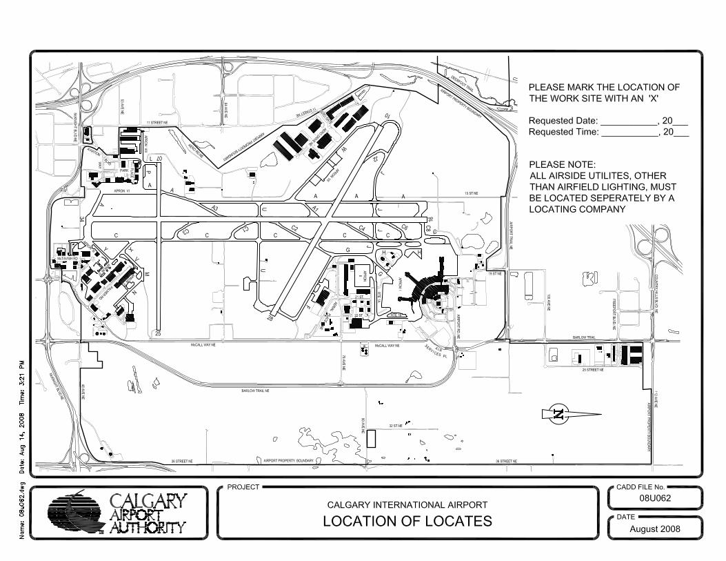
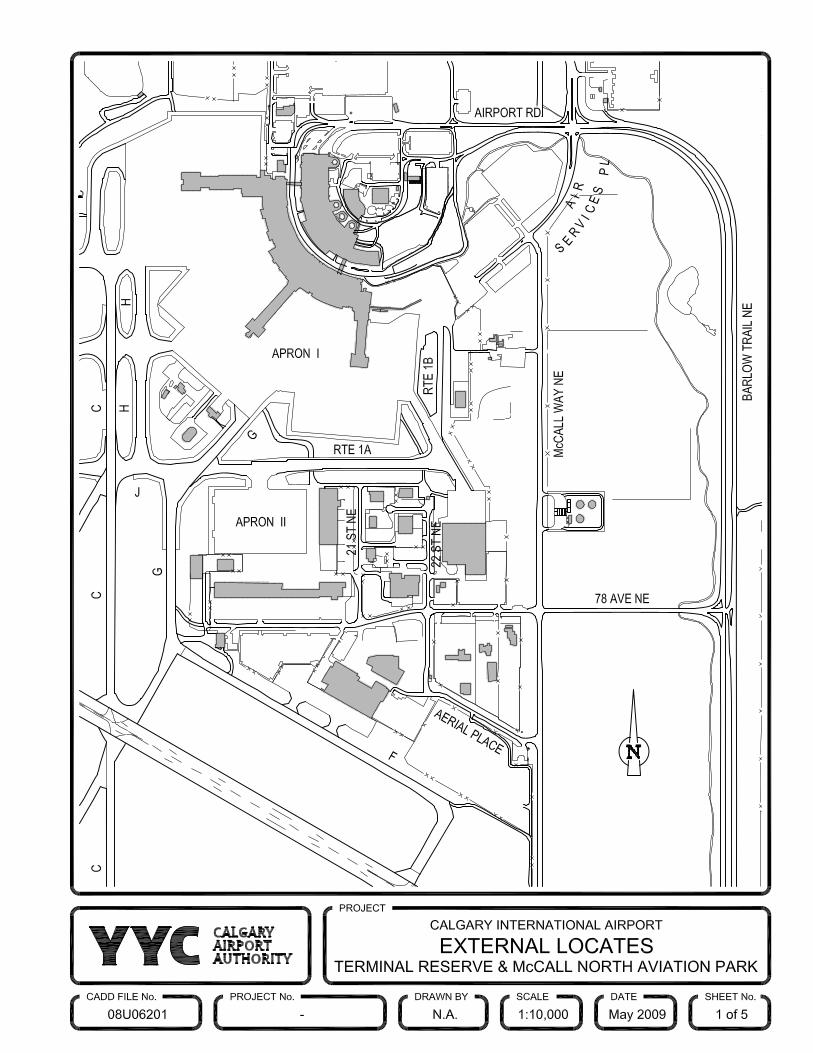
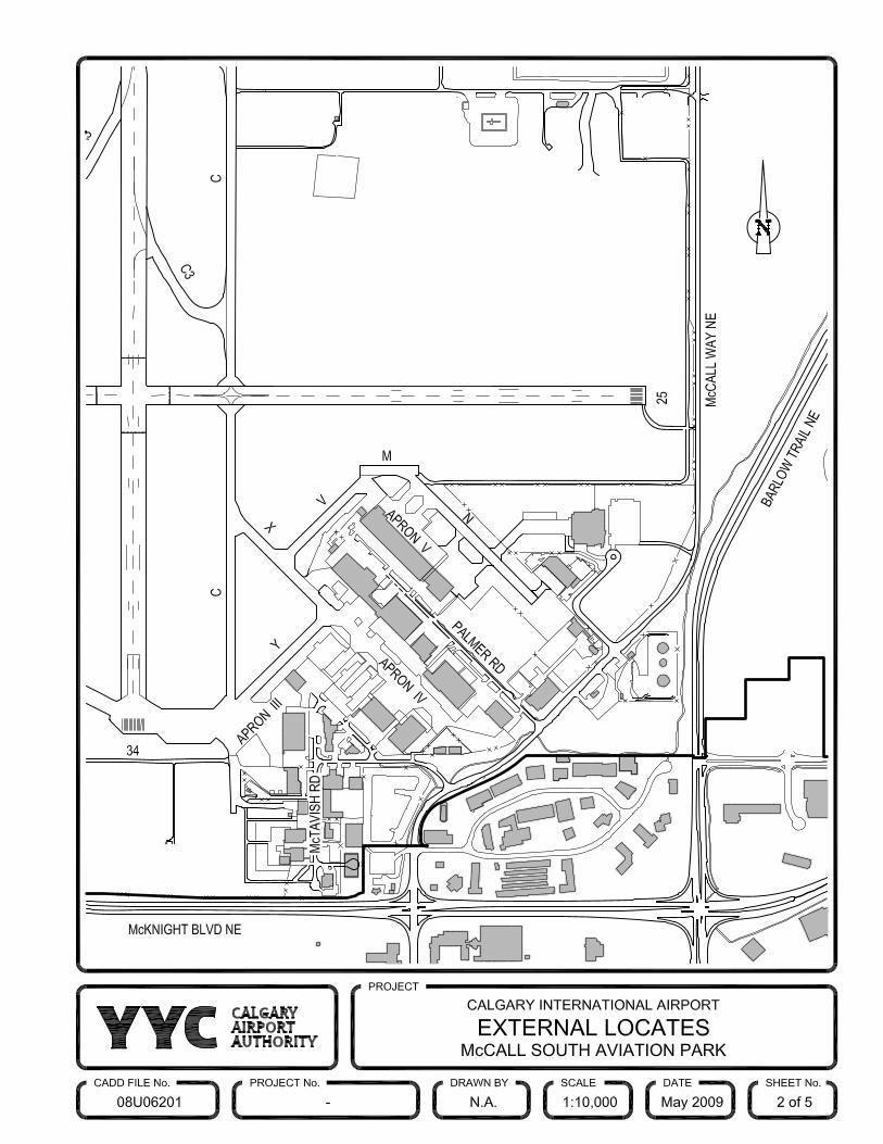

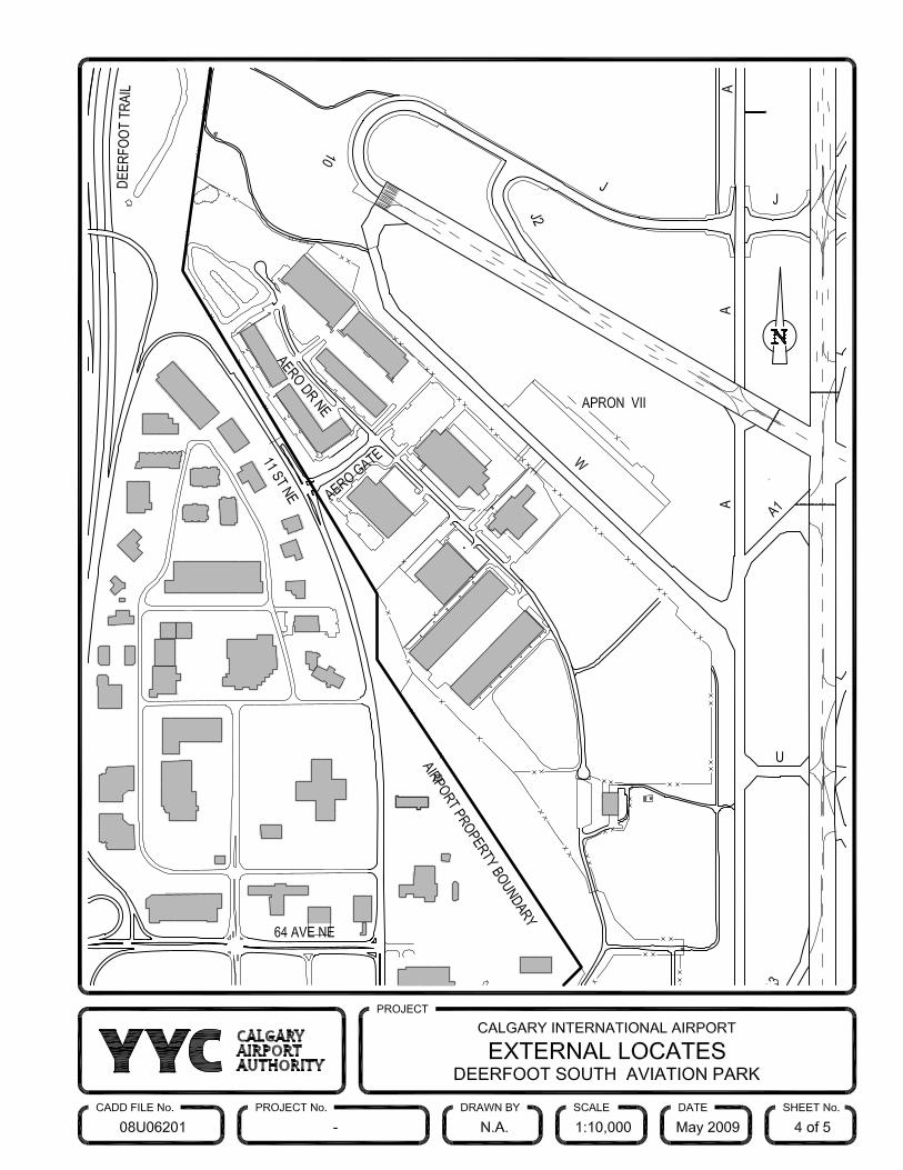
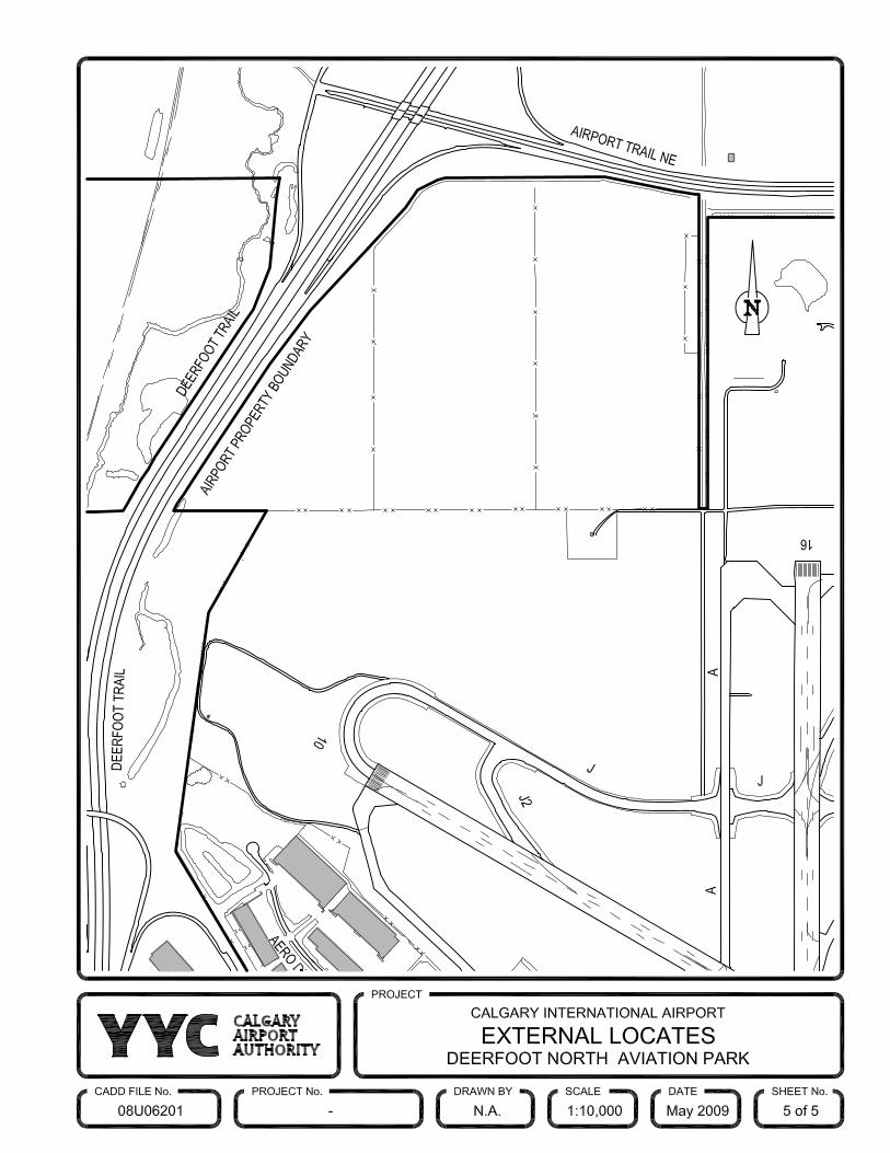
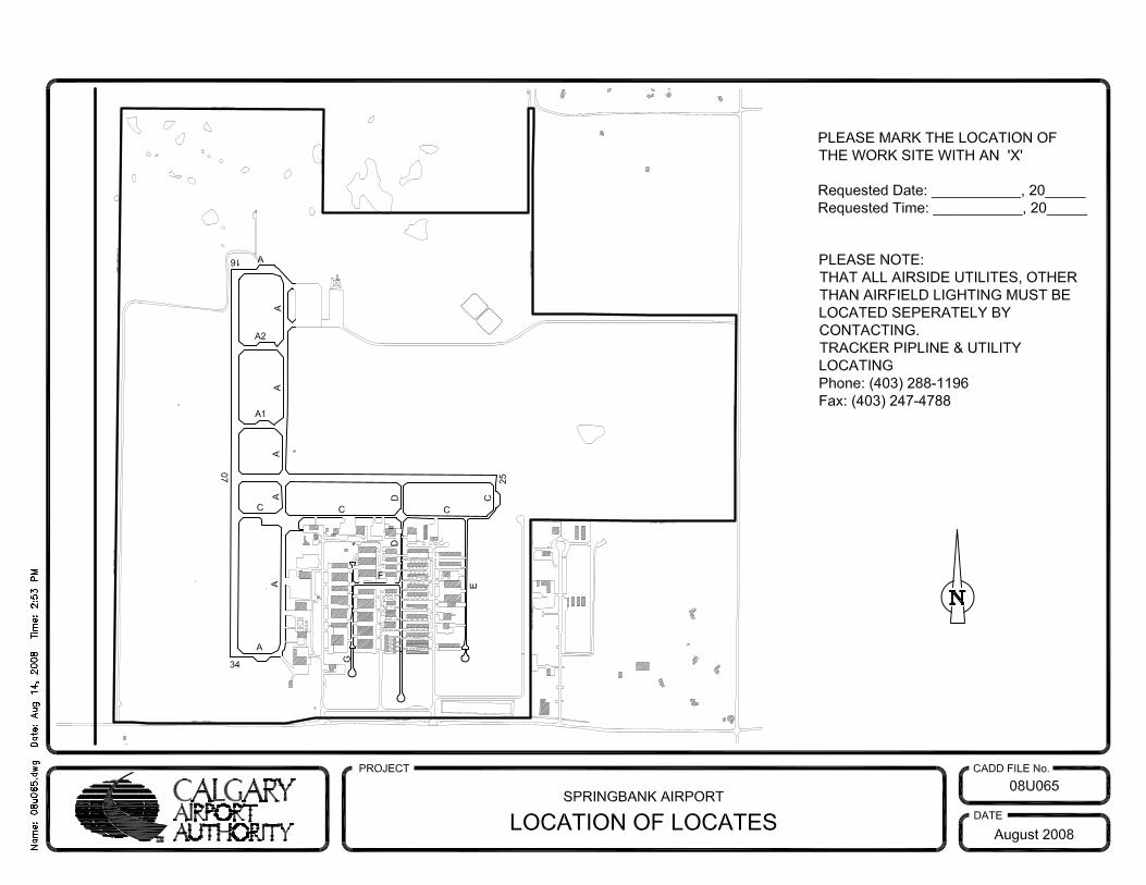

Appendix “C” Calgary Airport CADD Manual
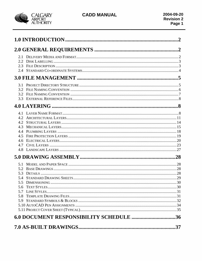
CADD MANUAL
2004-09-20Revision 2
Page 1
1.0 INTRODUCTION.....................................................................................2
2.0 GENERAL REQUIREMENTS ...............................................................2
2.1 DELIVERY MEDIA AND FORMAT.......................................................................................................2 2.2 DISK LABELLING ..............................................................................................................................3 2.3 FILE DESCRIPTION ............................................................................................................................3 2.4 STANDARD CO-ORDINATE SYSTEMS.................................................................................................4
3.0 FILE MANAGEMENT ............................................................................5
3.1 PROJECT DIRECTORY STRUCTURE ....................................................................................................5 3.2 FILE NAMING CONVENTION .............................................................................................................6 3.2 FILE NAMING CONVENTION .............................................................................................................7 3.3 EXTERNAL REFERENCE FILES...........................................................................................................8
4.0 LAYERING ...............................................................................................8
4.1 LAYER NAME FORMAT.....................................................................................................................8 4.2 ARCHITECTURAL LAYERS...............................................................................................................11 4.2 STRUCTURAL LAYERS ....................................................................................................................14 4.3 MECHANICAL LAYERS....................................................................................................................15 4.4 PLUMBING LAYERS ........................................................................................................................18 4.5 FIRE PROTECTION LAYERS .............................................................................................................19 4.6 ELECTRICAL LAYERS......................................................................................................................20 4.7 CIVIL LAYERS ................................................................................................................................23 4.8 LANDSCAPE LAYERS ......................................................................................................................27
5.0 DRAWING ASSEMBLY........................................................................28
5.1 MODEL AND PAPER SPACE .............................................................................................................28 5.2 BASE DRAWINGS ............................................................................................................................28 5.3 DETAILS .........................................................................................................................................28 5.4 STANDARD DRAWING SHEETS........................................................................................................29 5.5 DIMENSIONING ...............................................................................................................................30 5.6 TEXT STYLES..................................................................................................................................30 5.7 LINE STYLES...................................................................................................................................31 5.8 TEMPLATE DRAWING FILES............................................................................................................31 5.9 STANDARD SYMBOLS & BLOCKS ...................................................................................................32 5.10 AUTOCAD PEN ASSIGNMENTS ......................................................................................................34 5.11 PROJECT COVER SHEET (TYPICAL).................................................................................................35
6.0 DOCUMENT RESPONSIBILITY SCHEDULE .................................36
7.0 AS-BUILT DRAWINGS.........................................................................37
CADD MANUAL
2004-09-20Revision 2
Page 2
1.0 INTRODUCTION
This Computer Aided Design and Drafting Standards package is to be used on all Calgary Airport Authority (Airport Authority) projects. These standards have been developed to serve as a guide and overview for all disciplines of CADD on internal and contractually submitted electronic drawing file formats. Highlights within this manual include file format, naming conventions, layering, drawing assembly and general drafting procedures. Consultants shall contact the Technical Data Centre (TDC) for updates and revisions to the standards and must ensure the most current issue of the Airport Authority CADD Manual is being used. The file structure, drawing numbering, primary layer names and standard detail symbology shall be adhered to. Changes to the standards symbology or layering groups may be considered upon formal request to the TDC. The Airport Authority must approve these modifications, in advance, and the modifications shall be documented in writing with the drawing submission. Facility record drawings are available for Consultants use on Airport Authority projects. While every attempt is made to ensure the information in the record drawings is correct, consultants should verify all-critical information, systems and dimensions and obtain any missing information. Access to original as-built information is permitted and can be arranged through project manager and TDC. The Airport Authority is currently utilising Autodesk Map 2004, AutoDesk Land Desktop 2004 with Civil/Survey enhancement packages and Autodesk Architectural Desktop 2004 enhanced with Building Systems 2004. The airport has adopted the use of the AIA Layer Guidelines - Long Layer Name Format for its CADD layering convention.
2.0 GENERAL REQUIREMENTS
2.1 Delivery Media and Format All information described in section 2.0 of this document is to be included in the electronic data deliverables. Any additional files developed as part of the project such as construction specifications, XML Databases shall also be provided with the drawing sets. Deliverables are to be provided on CD-ROM. Drawing files will be saved in AutoCAD 2004 format (.dwg). If not upgraded to Autocad 2004, version 2000 or R14 formats will be acceptable. The submitter is responsible for archiving the electronic data until final written acceptance from the Airport Authority has been issued. Electronic data deliverables are required with all major submittals unless otherwise directed by Contract Agreements. Filenames
• drawing / filename provided by the Airport Authority • long filenames will be accepted by the Airport Authority • refer to section 3.2 for file naming conventions
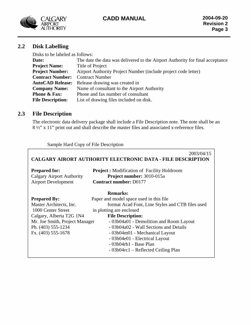
CADD MANUAL
2004-09-20Revision 2
Page 3
2.2 Disk Labelling
Disks to be labeled as follows: Date: The date the data was delivered to the Airport Authority for final acceptance Project Name: Title of Project Project Number: Airport Authority Project Number (include project code letter) Contract Number: Contract Number AutoCAD Release: Release drawing was created in Company Name: Name of consultant to the Airport Authority Phone & Fax: Phone and fax number of consultant File Description: List of drawing files included on disk.
2.3 File Description The electronic data delivery package shall include a File Description note. The note shall be an 8 ½” x 11” print out and shall describe the master files and associated x-reference files.
Sample Hard Copy of File Description
2003/04/15CALGARY AIRORT AUTHORITY ELECTRONIC DATA - FILE DESCRIPTION Prepared for: Project : Modification of Facility Holdroom Calgary Airport Authority Project number: 3010-015a Airport Development Contract number: D0177 Remarks: Prepared By: Paper and model space used in this file Master Architects, Inc. format Acad Font, Line Styles and CTB files used 1000 Center Street in plotting are enclosed Calgary, Alberta T2G 1N4 File Description: Mr. Joe Smith, Project Manager - 03b04a01 - Demolition and Room Layout Ph. (403) 555-1234 - 03b04a02 - Wall Sections and Details Fx. (403) 555-1678 - 03b04m01 - Mechanical Layout
- 03b04e01 - Electrical Layout - 03b04rb1 - Base Plan - 03b04rc1 – Reflected Ceiling Plan
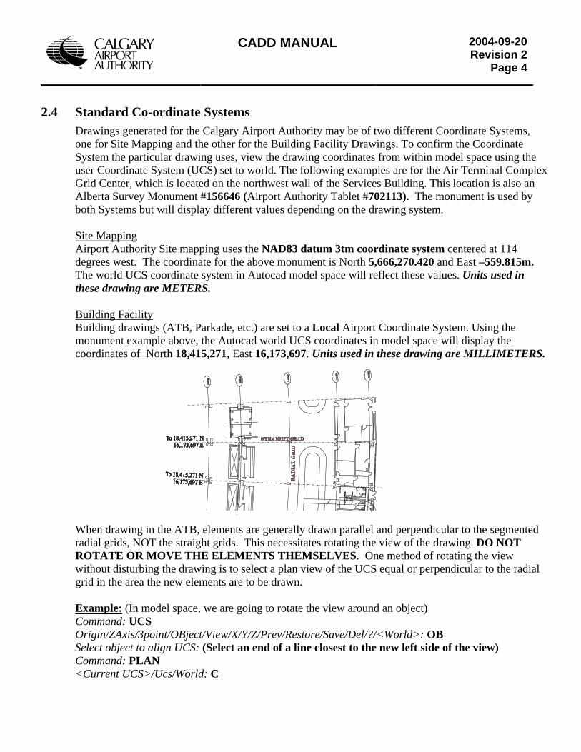
CADD MANUAL
2004-09-20Revision 2
Page 4
2.4 Standard Co-ordinate Systems Drawings generated for the Calgary Airport Authority may be of two different Coordinate Systems, one for Site Mapping and the other for the Building Facility Drawings. To confirm the Coordinate System the particular drawing uses, view the drawing coordinates from within model space using the user Coordinate System (UCS) set to world. The following examples are for the Air Terminal Complex Grid Center, which is located on the northwest wall of the Services Building. This location is also an Alberta Survey Monument #156646 (Airport Authority Tablet #702113). The monument is used by both Systems but will display different values depending on the drawing system. Site Mapping Airport Authority Site mapping uses the NAD83 datum 3tm coordinate system centered at 114 degrees west. The coordinate for the above monument is North 5,666,270.420 and East –559.815m. The world UCS coordinate system in Autocad model space will reflect these values. Units used in these drawing are METERS. Building Facility Building drawings (ATB, Parkade, etc.) are set to a Local Airport Coordinate System. Using the monument example above, the Autocad world UCS coordinates in model space will display the coordinates of North 18,415,271, East 16,173,697. Units used in these drawing are MILLIMETERS.
When drawing in the ATB, elements are generally drawn parallel and perpendicular to the segmented radial grids, NOT the straight grids. This necessitates rotating the view of the drawing. DO NOT ROTATE OR MOVE THE ELEMENTS THEMSELVES. One method of rotating the view without disturbing the drawing is to select a plan view of the UCS equal or perpendicular to the radial grid in the area the new elements are to be drawn.
Example: (In model space, we are going to rotate the view around an object) Command: UCS Origin/ZAxis/3point/OBject/View/X/Y/Z/Prev/Restore/Save/Del/?/<World>: OB Select object to align UCS: (Select an end of a line closest to the new left side of the view) Command: PLAN <Current UCS>/Ucs/World: C
CADD MANUAL
2004-09-20Revision 2
Page 5
3.0 FILE MANAGEMENT
3.1 Project Directory Structure Directory structures shall be created for all in-house generated Capital projects. Projects not requiring all disciplines do not need to have all discipline levels created. All drawings will be located within the directory structure as indicated below.
Project Number Level – this number will be provided by the Airport Authority Project Manager. For projects that have multiple tendered contracts, ensure to use Project Number Sub Letter to describe the project directory (3010-015a). No drawings are located at this level.
Discipline Level - only title block/fence drawings (. DWG) are located at this level. Details, plans etc, from component level will be X-referenced onto title block/fence drawings from the BLK directory.
C - Civil / Landscaping drawings A - Architectural drawings E - Electrical drawings I - Interior drawing M - Mechanical/Plumbing/Fire Protection drawings S - Structural drawings T - Telecommunication Drawings Prel - Preliminary/Schematic design drawings Spec - All discipline specifications, schedules addendum. Admin - All administrative files such as correspondence, technical data, production drawing lists and schedules etc.
Component Level BLK - Final drawing component elements are located in this directory. Components are
X-referenced onto title blocks/fences.
Directory Structure - Consultants are not required to follow Airport Authority directory structure, but are required to provide files that will fit into the Airport Authority file System. Options are available to deal with Autocad xref file pathing as follows; 1) Placement of all plot sheets and xref files in one directory 2) When sub-directories are required, use parent file pathing example: .\BLK\xxxxx.dwg Use a “.” to
indicate parent, then followed by the sub-directories as required. 3) Autocad command “e-transmit” with the selection to remove xref paths.
These above methods will allow the project drawings to move into the Airport Authority file System and allow Autocad to resolve the xref paths.
The use of XREF binding is not considered to be acceptable option nor is directory hard pathing. Again, we ask that you DO NOT use xref binding or hard pathing.
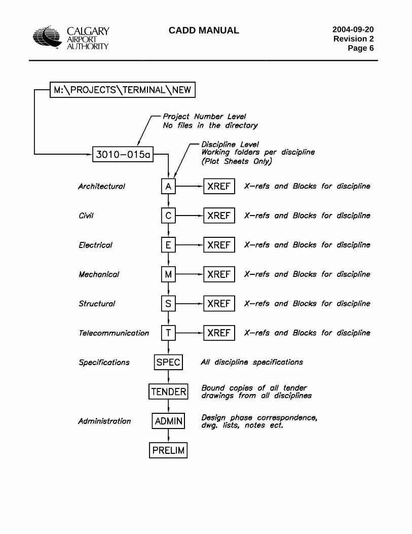
CADD MANUAL
2004-09-20Revision 2
Page 6
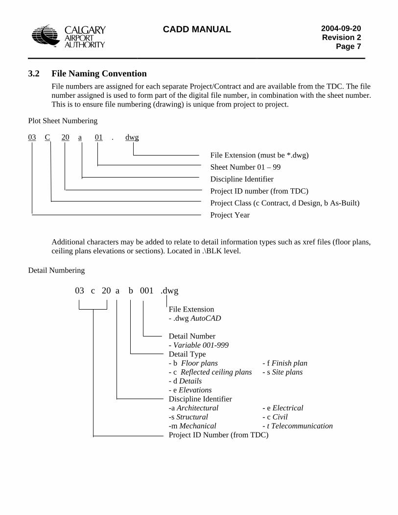
CADD MANUAL
2004-09-20Revision 2
Page 7
3.2 File Naming Convention
File numbers are assigned for each separate Project/Contract and are available from the TDC. The file number assigned is used to form part of the digital file number, in combination with the sheet number. This is to ensure file numbering (drawing) is unique from project to project.
Plot Sheet Numbering 03 C 20 a 01 . dwg
File Extension (must be *.dwg)
Sheet Number 01 – 99
Discipline Identifier
Project ID number (from TDC)
Project Class (c Contract, d Design, b As-Built)
Project Year
Additional characters may be added to relate to detail information types such as xref files (floor plans, ceiling plans elevations or sections). Located in .\BLK level.
Detail Numbering
03 c 20 a b 001 .dwg File Extension
- .dwg AutoCAD Detail Number
- Variable 001-999 Detail Type
- b Floor plans - f Finish plan - c Reflected ceiling plans - s Site plans - d Details - e Elevations
Discipline Identifier -a Architectural - e Electrical -s Structural - c Civil -m Mechanical - t Telecommunication Project ID Number (from TDC)
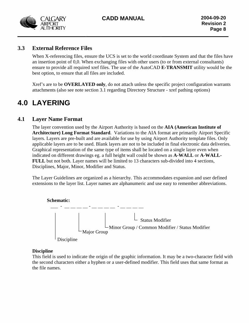
CADD MANUAL
2004-09-20Revision 2
Page 8
3.3 External Reference Files When X-referencing files, ensure the UCS is set to the world coordinate System and that the files have an insertion point of 0,0. When exchanging files with other users (to or from external consultants) ensure to provide all required xref files. The use of the AutoCAD E-TRANSMIT utility would be the best option, to ensure that all files are included. Xref’s are to be OVERLAYED only, do not attach unless the specific project configuration warrants attachments (also see note section 3.1 regarding Directory Structure - xref pathing options)
4.0 LAYERING
4.1 Layer Name Format The layer convention used by the Airport Authority is based on the AIA (American Institute of Architecture) Long Format Standard. Variations to the AIA format are primarily Airport Specific layers. Layers are pre-built and are available for use by using Airport Authority template files. Only applicable layers are to be used. Blank layers are not to be included in final electronic data deliveries. Graphical representation of the same type of items shall be located on a single layer even when indicated on different drawings eg. a full height wall could be shown as A-WALL or A-WALL-FULL but not both. Layer names will be limited to 13 characters sub-divided into 4 sections, Disciplines, Major, Minor, Modifier and Status. The Layer Guidelines are organized as a hierarchy. This accommodates expansion and user defined extensions to the layer list. Layer names are alphanumeric and use easy to remember abbreviations.
Schematic: ___ - __ __ __ __ - __ __ __ __ - __ __ __ __
Major Group Minor Group / Common Modifier / Status Modifier
Discipline
Status Modifier
Discipline This field is used to indicate the origin of the graphic information. It may be a two-character field with the second characters either a hyphen or a user-defined modifier. This field uses that same format as the file names.
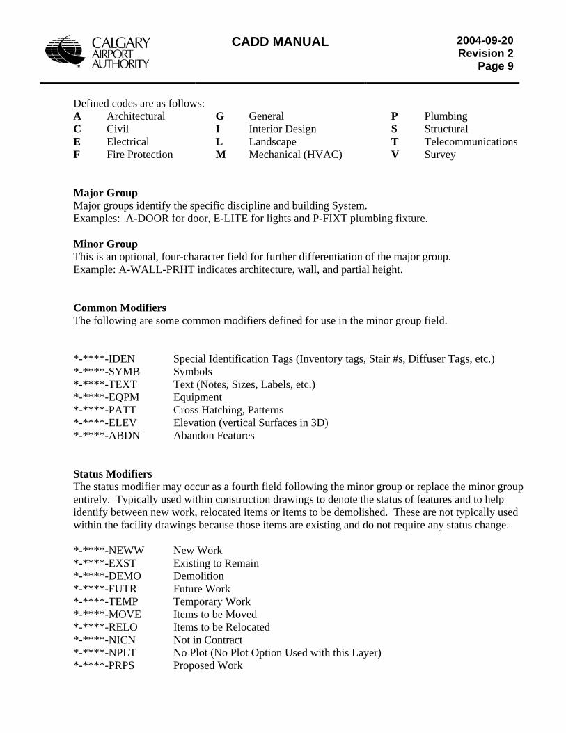
CADD MANUAL
2004-09-20Revision 2
Page 9
Defined codes are as follows: A Architectural
C Civil E Electrical F Fire Protection
G General I Interior Design L Landscape M Mechanical (HVAC)
P Plumbing S Structural T Telecommunications V Survey
Major Group Major groups identify the specific discipline and building System. Examples: A-DOOR for door, E-LITE for lights and P-FIXT plumbing fixture. Minor Group This is an optional, four-character field for further differentiation of the major group. Example: A-WALL-PRHT indicates architecture, wall, and partial height. Common Modifiers The following are some common modifiers defined for use in the minor group field. *-****-IDEN Special Identification Tags (Inventory tags, Stair #s, Diffuser Tags, etc.) *-****-SYMB Symbols *-****-TEXT Text (Notes, Sizes, Labels, etc.) *-****-EQPM Equipment *-****-PATT Cross Hatching, Patterns *-****-ELEV Elevation (vertical Surfaces in 3D) *-****-ABDN Abandon Features Status Modifiers The status modifier may occur as a fourth field following the minor group or replace the minor group entirely. Typically used within construction drawings to denote the status of features and to help identify between new work, relocated items or items to be demolished. These are not typically used within the facility drawings because those items are existing and do not require any status change. *-****-NEWW New Work *-****-EXST Existing to Remain *-****-DEMO Demolition *-****-FUTR Future Work *-****-TEMP Temporary Work *-****-MOVE Items to be Moved *-****-RELO Items to be Relocated *-****-NICN Not in Contract *-****-NPLT No Plot (No Plot Option Used with this Layer) *-****-PRPS Proposed Work
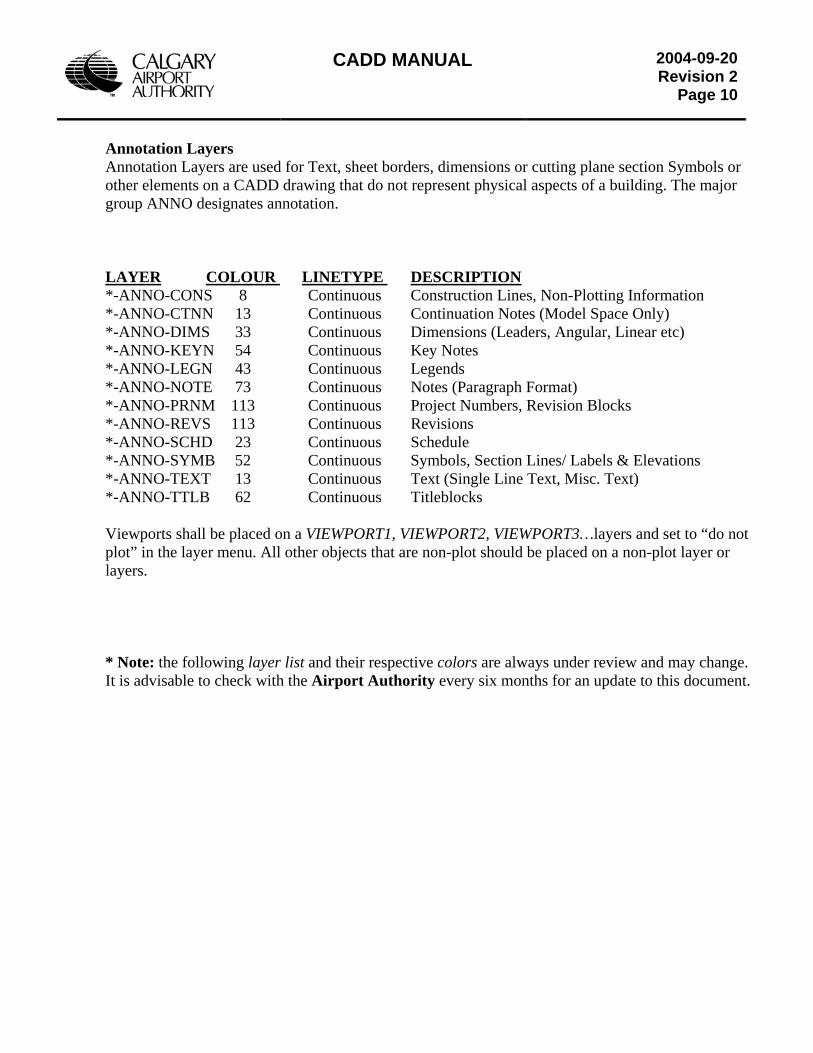
CADD MANUAL
2004-09-20Revision 2
Page 10
Annotation Layers Annotation Layers are used for Text, sheet borders, dimensions or cutting plane section Symbols or other elements on a CADD drawing that do not represent physical aspects of a building. The major group ANNO designates annotation. LAYER COLOUR LINETYPE DESCRIPTION*-ANNO-CONS 8 Continuous Construction Lines, Non-Plotting Information *-ANNO-CTNN 13 Continuous Continuation Notes (Model Space Only) *-ANNO-DIMS 33 Continuous Dimensions (Leaders, Angular, Linear etc) *-ANNO-KEYN 54 Continuous Key Notes *-ANNO-LEGN 43 Continuous Legends *-ANNO-NOTE 73 Continuous Notes (Paragraph Format) *-ANNO-PRNM 113 Continuous Project Numbers, Revision Blocks *-ANNO-REVS 113 Continuous Revisions *-ANNO-SCHD 23 Continuous Schedule *-ANNO-SYMB 52 Continuous Symbols, Section Lines/ Labels & Elevations *-ANNO-TEXT 13 Continuous Text (Single Line Text, Misc. Text) *-ANNO-TTLB 62 Continuous Titleblocks Viewports shall be placed on a VIEWPORT1, VIEWPORT2, VIEWPORT3…layers and set to “do not plot” in the layer menu. All other objects that are non-plot should be placed on a non-plot layer or layers. * Note: the following layer list and their respective colors are always under review and may change. It is advisable to check with the Airport Authority every six months for an update to this document.
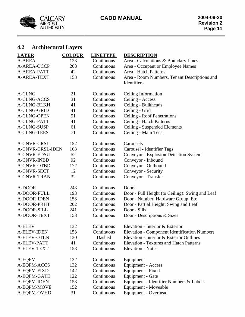
CADD MANUAL
2004-09-20Revision 2
Page 11
4.2 Architectural Layers LAYER COLOUR LINETYPE DESCRIPTION A-AREA 123 Continuous Area - Calculations & Boundary Lines A-AREA-OCCP 203 Continuous Area - Occupant or Employee Names A-AREA-PATT 42 Continuous Area - Hatch Patterns A-AREA-TEXT 153 Continuous Area - Room Numbers, Tenant Descriptions and Identifiers A-CLNG 21 Continuous Ceiling Information A-CLNG-ACCS 31 Continuous Ceiling - Access A-CLNG-BLKH 41 Continuous Ceiling - Bulkheads A-CLNG-GRID 41 Continuous Ceiling - Grid A-CLNG-OPEN 51 Continuous Ceiling - Roof Penetrations A-CLNG-PATT 41 Continuous Ceiling - Hatch Patterns A-CLNG-SUSP 61 Continuous Ceiling - Suspended Elements A-CLNG-TEES 71 Continuous Ceiling - Main Tees A-CNVR-CRSL 152 Continuous Carousels A-CNVR-CRSL-IDEN 163 Continuous Carousel - Identifier Tags A-CNVR-EDSU 52 Continuous Conveyor - Explosion Detection System A-CNVR-INBD 92 Continuous Conveyor - Inbound A-CNVR-OTBD 172 Continuous Conveyor - Outbound A-CNVR-SECT 12 Continuous Conveyor - Security A-CNVR-TRAN 32 Continuous Conveyor - Transfer A-DOOR 243 Continuous Doors A-DOOR-FULL 193 Continuous Door - Full Height (to Ceiling): Swing and Leaf A-DOOR-IDEN 153 Continuous Door - Number, Hardware Group, Etc A-DOOR-PRHT 202 Continuous Door - Partial Height: Swing and Leaf A-DOOR-SILL 241 Continuous Door - Sills A-DOOR-TEXT 153 Continuous Door - Descriptions & Sizes A-ELEV 132 Continuous Elevation - Interior & Exterior A-ELEV-IDEN 153 Continuous Elevation - Component Identification Numbers A-ELEV-OTLN 130 Dashed Elevation - Interior & Exterior Outlines A-ELEV-PATT 41 Continuous Elevation - Textures and Hatch Patterns A-ELEV-TEXT 153 Continuous Elevation - Notes A-EQPM 132 Continuous Equipment A-EQPM-ACCS 132 Continuous Equipment - Access A-EQPM-FIXD 142 Continuous Equipment - Fixed A-EQPM-GATE 122 Continuous Equipment - Gate A-EQPM-IDEN 153 Continuous Equipment - Identifier Numbers & Labels A-EQPM-MOVE 152 Continuous Equipment - Moveable A-EQPM-OVHD 31 Continuous Equipment - Overhead
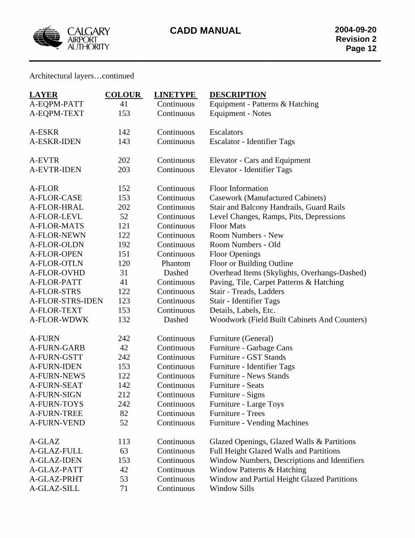
CADD MANUAL
2004-09-20Revision 2
Page 12
Architectural layers…continued LAYER COLOUR LINETYPE DESCRIPTIONA-EQPM-PATT 41 Continuous Equipment - Patterns & Hatching A-EQPM-TEXT 153 Continuous Equipment - Notes A-ESKR 142 Continuous Escalators A-ESKR-IDEN 143 Continuous Escalator - Identifier Tags A-EVTR 202 Continuous Elevator - Cars and Equipment A-EVTR-IDEN 203 Continuous Elevator - Identifier Tags A-FLOR 152 Continuous Floor Information A-FLOR-CASE 153 Continuous Casework (Manufactured Cabinets) A-FLOR-HRAL 202 Continuous Stair and Balcony Handrails, Guard Rails A-FLOR-LEVL 52 Continuous Level Changes, Ramps, Pits, Depressions A-FLOR-MATS 121 Continuous Floor Mats A-FLOR-NEWN 122 Continuous Room Numbers - New A-FLOR-OLDN 192 Continuous Room Numbers - Old A-FLOR-OPEN 151 Continuous Floor Openings A-FLOR-OTLN 120 Phantom Floor or Building Outline A-FLOR-OVHD 31 Dashed Overhead Items (Skylights, Overhangs-Dashed) A-FLOR-PATT 41 Continuous Paving, Tile, Carpet Patterns & Hatching A-FLOR-STRS 122 Continuous Stair - Treads, Ladders A-FLOR-STRS-IDEN 123 Continuous Stair - Identifier Tags A-FLOR-TEXT 153 Continuous Details, Labels, Etc. A-FLOR-WDWK 132 Dashed Woodwork (Field Built Cabinets And Counters) A-FURN 242 Continuous Furniture (General) A-FURN-GARB 42 Continuous Furniture - Garbage Cans A-FURN-GSTT 242 Continuous Furniture - GST Stands A-FURN-IDEN 153 Continuous Furniture - Identifier Tags A-FURN-NEWS 122 Continuous Furniture - News Stands A-FURN-SEAT 142 Continuous Furniture - Seats A-FURN-SIGN 212 Continuous Furniture - Signs A-FURN-TOYS 242 Continuous Furniture - Large Toys A-FURN-TREE 82 Continuous Furniture - Trees A-FURN-VEND 52 Continuous Furniture - Vending Machines A-GLAZ 113 Continuous Glazed Openings, Glazed Walls & Partitions A-GLAZ-FULL 63 Continuous Full Height Glazed Walls and Partitions A-GLAZ-IDEN 153 Continuous Window Numbers, Descriptions and Identifiers A-GLAZ-PATT 42 Continuous Window Patterns & Hatching A-GLAZ-PRHT 53 Continuous Window and Partial Height Glazed Partitions A-GLAZ-SILL 71 Continuous Window Sills
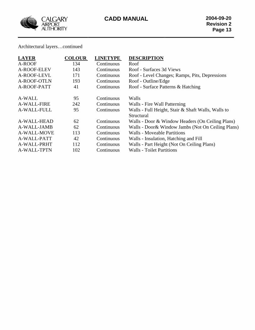
CADD MANUAL
2004-09-20Revision 2
Page 13
Architectural layers…continued LAYER COLOUR LINETYPE DESCRIPTIONA-ROOF 134 Continuous Roof A-ROOF-ELEV 143 Continuous Roof - Surfaces 3d Views A-ROOF-LEVL 171 Continuous Roof - Level Changes; Ramps, Pits, Depressions A-ROOF-OTLN 193 Continuous Roof - Outline/Edge A-ROOF-PATT 41 Continuous Roof - Surface Patterns & Hatching A-WALL 95 Continuous Walls A-WALL-FIRE 242 Continuous Walls - Fire Wall Patterning A-WALL-FULL 95 Continuous Walls - Full Height, Stair & Shaft Walls, Walls to Structural A-WALL-HEAD 62 Continuous Walls - Door & Window Headers (On Ceiling Plans) A-WALL-JAMB 62 Continuous Walls - Door& Window Jambs (Not On Ceiling Plans) A-WALL-MOVE 113 Continuous Walls - Moveable Partitions A-WALL-PATT 42 Continuous Walls - Insulation, Hatching and Fill A-WALL-PRHT 112 Continuous Walls - Part Height (Not On Ceiling Plans) A-WALL-TPTN 102 Continuous Walls - Toilet Partitions
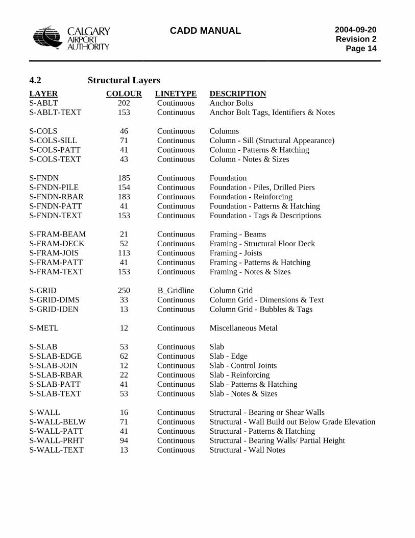
CADD MANUAL
2004-09-20Revision 2
Page 14
4.2 Structural Layers LAYER COLOUR LINETYPE DESCRIPTION S-ABLT 202 Continuous Anchor Bolts S-ABLT-TEXT 153 Continuous Anchor Bolt Tags, Identifiers & Notes S-COLS 46 Continuous Columns S-COLS-SILL 71 Continuous Column - Sill (Structural Appearance) S-COLS-PATT 41 Continuous Column - Patterns & Hatching S-COLS-TEXT 43 Continuous Column - Notes & Sizes S-FNDN 185 Continuous Foundation S-FNDN-PILE 154 Continuous Foundation - Piles, Drilled Piers S-FNDN-RBAR 183 Continuous Foundation - Reinforcing S-FNDN-PATT 41 Continuous Foundation - Patterns & Hatching S-FNDN-TEXT 153 Continuous Foundation - Tags & Descriptions S-FRAM-BEAM 21 Continuous Framing - Beams S-FRAM-DECK 52 Continuous Framing - Structural Floor Deck S-FRAM-JOIS 113 Continuous Framing - Joists S-FRAM-PATT 41 Continuous Framing - Patterns & Hatching S-FRAM-TEXT 153 Continuous Framing - Notes & Sizes S-GRID 250 B_Gridline Column Grid S-GRID-DIMS 33 Continuous Column Grid - Dimensions & Text S-GRID-IDEN 13 Continuous Column Grid - Bubbles & Tags S-METL 12 Continuous Miscellaneous Metal S-SLAB 53 Continuous Slab S-SLAB-EDGE 62 Continuous Slab - Edge S-SLAB-JOIN 12 Continuous Slab - Control Joints S-SLAB-RBAR 22 Continuous Slab - Reinforcing S-SLAB-PATT 41 Continuous Slab - Patterns & Hatching S-SLAB-TEXT 53 Continuous Slab - Notes & Sizes S-WALL 16 Continuous Structural - Bearing or Shear Walls S-WALL-BELW 71 Continuous Structural - Wall Build out Below Grade Elevation S-WALL-PATT 41 Continuous Structural - Patterns & Hatching S-WALL-PRHT 94 Continuous Structural - Bearing Walls/ Partial Height S-WALL-TEXT 13 Continuous Structural - Wall Notes
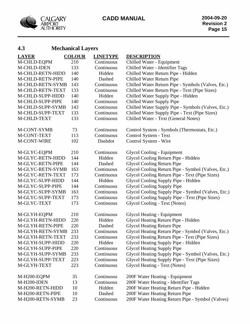
CADD MANUAL
2004-09-20Revision 2
Page 15
4.3 Mechanical Layers LAYER COLOUR LINETYPE DESCRIPTION M-CHLD-EQPM 210 Continuous Chilled Water - Equipment M-CHLD-IDEN 133 Continuous Chilled Water - Identifier Tags M-CHLD-RETN-HIDD 140 Hidden Chilled Water Return Pipe - Hidden M-CHLD-RETN-PIPE 140 Dashed Chilled Water Return Pipe M-CHLD-RETN-SYMB 143 Continuous Chilled Water Return Pipe - Symbols (Valves, Etc.) M-CHLD-RETN-TEXT 133 Continuous Chilled Water Return Pipe - Text (Pipe Sizes) M-CHLD-SUPP-HIDD 140 Hidden Chilled Water Supply Pipe - Hidden M-CHLD-SUPP-PIPE 140 Continuous Chilled Water Supply Pipe M-CHLD-SUPP-SYMB 143 Continuous Chilled Water Supply Pipe - Symbols (Valves, Etc.) M-CHLD-SUPP-TEXT 133 Continuous Chilled Water Supply Pipe - Text (Pipe Sizes) M-CHLD-TEXT 133 Continuous Chilled Water - Text (General Notes) M-CONT-SYMB 73 Continuous Control System - Symbols (Thermostats, Etc.) M-CONT-TEXT 113 Continuous Control System - Text M-CONT-WIRE 102 Dashdot Control System - Wire M-GLYC-EQPM 210 Continuous Glycol Cooling - Equipment M-GLYC-RETN-HIDD 144 Hidden Glycol Cooling Return Pipe - Hidden M-GLYC-RETN-PIPE 144 Dashed Glycol Cooling Return Pipe M-GLYC-RETN-SYMB 163 Continuous Glycol Cooling Return Pipe - Symbol (Valves, Etc.) M-GLYC-RETN-TEXT 173 Continuous Glycol Cooling Return Pipe - Text (Pipe Sizes) M-GLYC-SUPP-HIDD 144 Hidden Glycol Cooling Supply Pipe - Hidden M-GLYC-SUPP-PIPE 144 Continuous Glycol Cooling Supply Pipe M-GLYC-SUPP-SYMB 163 Continuous Glycol Cooling Supply Pipe - Symbol (Valves, Etc.) M-GLYC-SUPP-TEXT 173 Continuous Glycol Cooling Supply Pipe - Text (Pipe Sizes) M-GLYC-TEXT 173 Continuous Glycol Cooling - Text (Notes) M-GLYH-EQPM 210 Continuous Glycol Heating - Equipment M-GLYH-RETN-HIDD 220 Hidden Glycol Heating Return Pipe - Hidden M-GLYH-RETN-PIPE 220 Dashed Glycol Heating Return Pipe M-GLYH-RETN-SYMB 233 Continuous Glycol Heating Return Pipe - Symbol (Valves, Etc.) M-GLYH-RETN-TEXT 233 Continuous Glycol Heating Return Pipe - Text (Pipe Sizes) M-GLYH-SUPP-HIDD 220 Hidden Glycol Heating Supply Pipe - Hidden M-GLYH-SUPP-PIPE 220 Continuous Glycol Heating Supply Pipe M-GLYH-SUPP-SYMB 233 Continuous Glycol Heating Supply Pipe - Symbol (Valves, Etc.) M-GLYH-SUPP-TEXT 223 Continuous Glycol Heating Supply Pipe - Text (Pipe Sizes) M-GLYH-TEXT 223 Continuous Glycol Heating - Text (Notes) M-H200-EQPM 35 Continuous 200F Water Heating - Equipment M-H200-IDEN 13 Continuous 200F Water Heating - Identifier Tags M-H200-RETN-HIDD 10 Hidden 200F Water Heating Return Pipe - Hidden M-H200-RETN-PIPE 10 Dashed 200F Water Heating Return Pipe M-H200-RETN-SYMB 23 Continuous 200F Water Heating Return Pipe - Symbol (Valves)
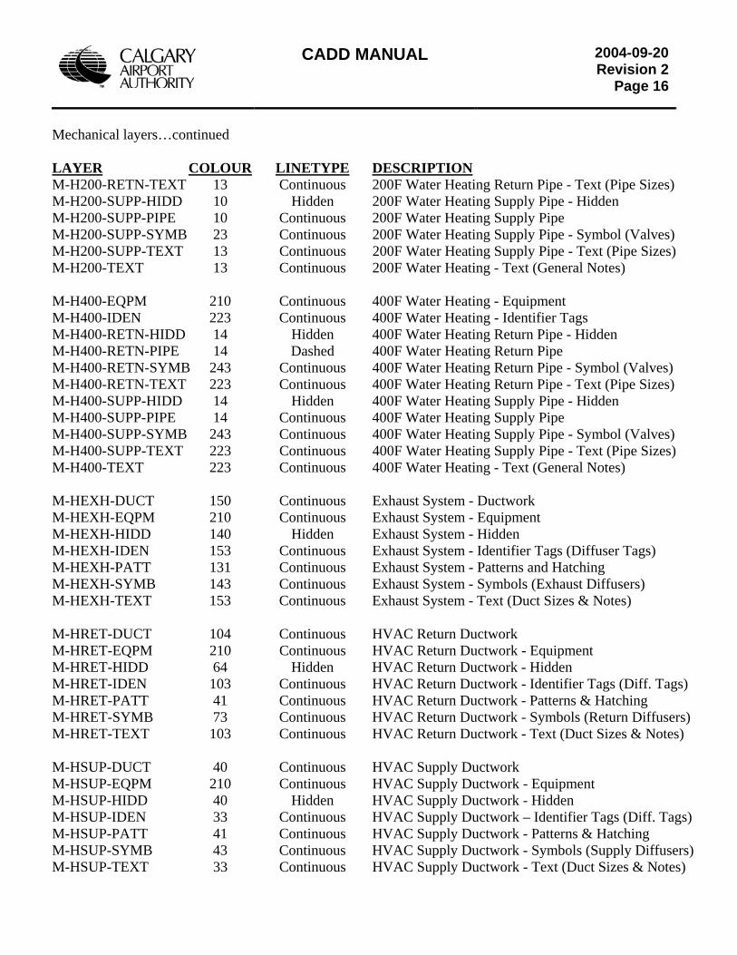
CADD MANUAL
2004-09-20Revision 2
Page 16
Mechanical layers…continued LAYER COLOUR LINETYPE DESCRIPTION M-H200-RETN-TEXT 13 Continuous 200F Water Heating Return Pipe - Text (Pipe Sizes) M-H200-SUPP-HIDD 10 Hidden 200F Water Heating Supply Pipe - Hidden M-H200-SUPP-PIPE 10 Continuous 200F Water Heating Supply Pipe M-H200-SUPP-SYMB 23 Continuous 200F Water Heating Supply Pipe - Symbol (Valves) M-H200-SUPP-TEXT 13 Continuous 200F Water Heating Supply Pipe - Text (Pipe Sizes) M-H200-TEXT 13 Continuous 200F Water Heating - Text (General Notes) M-H400-EQPM 210 Continuous 400F Water Heating - Equipment M-H400-IDEN 223 Continuous 400F Water Heating - Identifier Tags M-H400-RETN-HIDD 14 Hidden 400F Water Heating Return Pipe - Hidden M-H400-RETN-PIPE 14 Dashed 400F Water Heating Return Pipe M-H400-RETN-SYMB 243 Continuous 400F Water Heating Return Pipe - Symbol (Valves) M-H400-RETN-TEXT 223 Continuous 400F Water Heating Return Pipe - Text (Pipe Sizes) M-H400-SUPP-HIDD 14 Hidden 400F Water Heating Supply Pipe - Hidden M-H400-SUPP-PIPE 14 Continuous 400F Water Heating Supply Pipe M-H400-SUPP-SYMB 243 Continuous 400F Water Heating Supply Pipe - Symbol (Valves) M-H400-SUPP-TEXT 223 Continuous 400F Water Heating Supply Pipe - Text (Pipe Sizes) M-H400-TEXT 223 Continuous 400F Water Heating - Text (General Notes) M-HEXH-DUCT 150 Continuous Exhaust System - Ductwork M-HEXH-EQPM 210 Continuous Exhaust System - Equipment M-HEXH-HIDD 140 Hidden Exhaust System - Hidden M-HEXH-IDEN 153 Continuous Exhaust System - Identifier Tags (Diffuser Tags) M-HEXH-PATT 131 Continuous Exhaust System - Patterns and Hatching M-HEXH-SYMB 143 Continuous Exhaust System - Symbols (Exhaust Diffusers) M-HEXH-TEXT 153 Continuous Exhaust System - Text (Duct Sizes & Notes) M-HRET-DUCT 104 Continuous HVAC Return Ductwork M-HRET-EQPM 210 Continuous HVAC Return Ductwork - Equipment M-HRET-HIDD 64 Hidden HVAC Return Ductwork - Hidden M-HRET-IDEN 103 Continuous HVAC Return Ductwork - Identifier Tags (Diff. Tags) M-HRET-PATT 41 Continuous HVAC Return Ductwork - Patterns & Hatching M-HRET-SYMB 73 Continuous HVAC Return Ductwork - Symbols (Return Diffusers) M-HRET-TEXT 103 Continuous HVAC Return Ductwork - Text (Duct Sizes & Notes) M-HSUP-DUCT 40 Continuous HVAC Supply Ductwork M-HSUP-EQPM 210 Continuous HVAC Supply Ductwork - Equipment M-HSUP-HIDD 40 Hidden HVAC Supply Ductwork - Hidden M-HSUP-IDEN 33 Continuous HVAC Supply Ductwork – Identifier Tags (Diff. Tags) M-HSUP-PATT 41 Continuous HVAC Supply Ductwork - Patterns & Hatching M-HSUP-SYMB 43 Continuous HVAC Supply Ductwork - Symbols (Supply Diffusers) M-HSUP-TEXT 33 Continuous HVAC Supply Ductwork - Text (Duct Sizes & Notes)
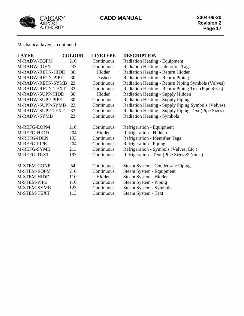
CADD MANUAL
2004-09-20Revision 2
Page 17
Mechanical layers…continued LAYER COLOUR LINETYPE DESCRIPTIONM-RADW-EQPM 210 Continuous Radiation Heating - Equipment M-RADW-IDEN 233 Continuous Radiation Heating - Identifier Tags M-RADW-RETN-HIDD 30 Hidden Radiation Heating - Return Hidden M-RADW-RETN-PIPE 30 Dashed Radiation Heating - Return Piping M-RADW-RETN-SYMB 23 Continuous Radiation Heating - Return Piping Symbols (Valves) M-RADW-RETN-TEXT 33 Continuous Radiation Heating - Return Piping Text (Pipe Sizes) M-RADW-SUPP-HIDD 30 Hidden Radiation Heating - Supply Hidden M-RADW-SUPP-PIPE 30 Continuous Radiation Heating - Supply Piping M-RADW-SUPP-SYMB 23 Continuous Radiation Heating - Supply Piping Symbols (Valves) M-RADW-SUPP-TEXT 33 Continuous Radiation Heating - Supply Piping Text (Pipe Sizes) M-RADW-SYMB 23 Continuous Radiation Heating - Symbols M-REFG-EQPM 210 Continuous Refrigeration - Equipment M-REFG-HIDD 204 Hidden Refrigeration - Hidden M-REFG-IDEN 193 Continuous Refrigeration - Identifier Tags M-REFG-PIPE 204 Continuous Refrigeration - Piping M-REFG-SYMB 213 Continuous Refrigeration - Symbols (Valves, Etc.) M-REFG-TEXT 193 Continuous Refrigeration - Text (Pipe Sizes & Notes) M-STEM-CONP 54 Continuous Steam System - Condensate Piping M-STEM-EQPM 210 Continuous Steam System - Equipment M-STEM-HIDD 110 Hidden Steam System - Hidden M-STEM-PIPE 110 Continuous Steam System - Piping M-STEM-SYMB 123 Continuous Steam System - Symbols M-STEM-TEXT 113 Continuous Steam System - Text
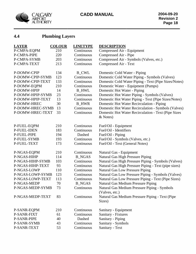
CADD MANUAL
2004-09-20Revision 2
Page 18
4.4 Plumbing Layers LAYER COLOUR LINETYPE DESCRIPTION P-CMPA-EQPM 210 Continuous Compressed Air - Equipment P-CMPA-PIPE 220 Continuous Compressed Air - Pipe P-CMPA-SYMB 203 Continuous Compressed Air - Symbols (Valves, etc.) P-CMPA-TEXT 213 Continuous Compressed Air - Text P-DOMW-CPIP 134 B_CWL Domestic Cold Water - Piping P-DOMW-CPIP-SYMB 123 Continuous Domestic Cold Water Piping - Symbols (Valves) P-DOMW-CPIP-TEXT 133 Continuous Domestic Cold Water Piping - Text (Pipe Sizes/Notes) P-DOMW-EQPM 210 Continuous Domestic Water - Equipment (Pumps) P-DOMW-HPIP 14 B_HWL Domestic Hot Water - Piping P-DOMW-HPIP-SYMB 23 Continuous Domestic Hot Water Piping - Symbols (Valves) P-DOMW-HPIP-TEXT 13 Continuous Domestic Hot Water Piping - Text (Pipe Sizes/Notes) P-DOMW-HREC 30 B_HWR Domestic Hot Water Recirculation - Piping P-DOMW-HREC-SYMB 13 Continuous Domestic Hot Water Recirculation - Symbols (Valves) P-DOMW-HREC-TEXT 33 Continuous Domestic Hot Water Recirculation - Text (Pipe Sizes & Notes) P-FUEL-EQPM 210 Continuous Fuel/Oil - Equipment P-FUEL-IDEN 183 Continuous Fuel/Oil - Identifiers P-FUEL-PIPE 194 Dashed Fuel/Oil - Piping P-FUEL-SYMB 193 Continuous Fuel/Oil - Symbols (Valves, etc.) P-FUEL-TEXT 173 Continuous Fuel/Oil - Text (General Notes) P-NGAS-EQPM 210 Continuous Natural Gas - Equipment P-NGAS-HIHP 114 B_NGAS Natural Gas High Pressure Piping P-NGAS-HIHP-SYMB 103 Continuous Natural Gas High Pressure Piping - Symbols (Valves) P-NGAS-HIHP-TEXT 93 Continuous Natural Gas High Pressure Piping - Text (pipe sizes) P-NGAS-LOWP 110 Continuous Natural Gas Low Pressure Piping P-NGAS-LOWP-SYMB 123 Continuous Natural Gas Low Pressure Piping - Symbols (Valves) P-NGAS-LOWP-TEXT 113 Continuous Natural Gas Low Pressure Piping - Text (Pipe Sizes) P-NGAS-MEDP 70 B_NGAS Natural Gas Medium Pressure Piping P-NGAS-MEDP-SYMB 73 Continuous Natural Gas Medium Pressure Piping - Symbols (Valves, etc.) P-NGAS-MEDP-TEXT 83 Continuous Natural Gas Medium Pressure Piping - Text (Pipe Sizes) P-SANR-EQPM 210 Continuous Sanitary - Equipment P-SANR-FIXT 61 Continuous Sanitary - Fixtures P-SANR-PIPE 40 Dashed Sanitary - Piping P-SANR-SYMB 43 Continuous Sanitary - Symbols P-SANR-TEXT 53 Continuous Sanitary - Text
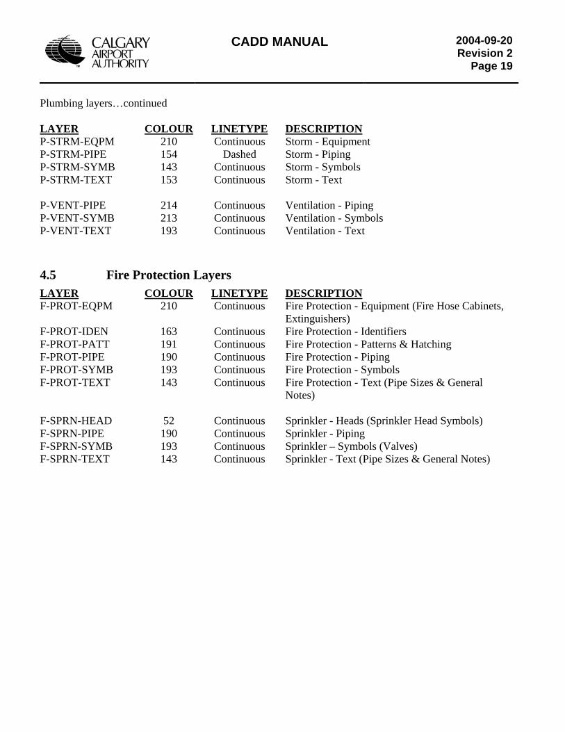
CADD MANUAL
2004-09-20Revision 2
Page 19
Plumbing layers…continued LAYER COLOUR LINETYPE DESCRIPTION P-STRM-EQPM 210 Continuous Storm - Equipment P-STRM-PIPE 154 Dashed Storm - Piping P-STRM-SYMB 143 Continuous Storm - Symbols P-STRM-TEXT 153 Continuous Storm - Text P-VENT-PIPE 214 Continuous Ventilation - Piping P-VENT-SYMB 213 Continuous Ventilation - Symbols P-VENT-TEXT 193 Continuous Ventilation - Text
4.5 Fire Protection Layers LAYER COLOUR LINETYPE DESCRIPTION F-PROT-EQPM 210 Continuous Fire Protection - Equipment (Fire Hose Cabinets, Extinguishers) F-PROT-IDEN 163 Continuous Fire Protection - Identifiers F-PROT-PATT 191 Continuous Fire Protection - Patterns & Hatching F-PROT-PIPE 190 Continuous Fire Protection - Piping F-PROT-SYMB 193 Continuous Fire Protection - Symbols F-PROT-TEXT 143 Continuous Fire Protection - Text (Pipe Sizes & General Notes) F-SPRN-HEAD 52 Continuous Sprinkler - Heads (Sprinkler Head Symbols) F-SPRN-PIPE 190 Continuous Sprinkler - Piping F-SPRN-SYMB 193 Continuous Sprinkler – Symbols (Valves) F-SPRN-TEXT 143 Continuous Sprinkler - Text (Pipe Sizes & General Notes)
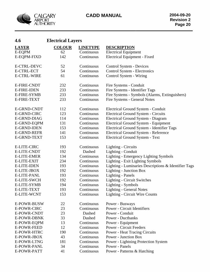
CADD MANUAL
2004-09-20Revision 2
Page 20
4.6 Electrical Layers LAYER COLOUR LINETYPE DESCRIPTION E-EQPM 62 Continuous Electrical Equipment E-EQPM-FIXD 142 Continuous Electrical Equipment - Fixed E-CTRL-DEVC 52 Continuous Control System - Devices E-CTRL-ECT 54 Continuous Control System - Electronics E-CTRL-WIRE 61 Continuous Control System - Wiring E-FIRE-CNDT 232 Continuous Fire Systems - Conduit E-FIRE-IDEN 233 Continuous Fire Systems - Identifier Tags E-FIRE-SYMB 233 Continuous Fire Systems - Symbols (Alarms, Extinguishers) E-FIRE-TEXT 233 Continuous Fire Systems - General Notes E-GRND-CNDT 112 Continuous Electrical Ground System - Conduit E-GRND-CIRC 123 Continuous Electrical Ground System - Circuits E-GRND-DIAG 114 Continuous Electrical Ground System - Diagram E-GRND-EQPM 131 Continuous Electrical Ground System - Equipment E-GRND-IDEN 153 Continuous Electrical Ground System - Identifier Tags E-GRND-REFR 141 Continuous Electrical Ground System - Reference E-GRND-TEXT 153 Continuous Electrical Ground System - Text E-LITE-CIRC 193 Continuous Lighting - Circuits E-LITE-CNDT 192 Dashed Lighting - Conduit E-LITE-EMER 134 Continuous Lighting - Emergency Lighting Symbols E-LITE-EXIT 234 Continuous Lighting - Exit Lighting Symbols E-LITE-IDEN 193 Continuous Lighting - Luminaries Descriptions & Identifier Tags E-LITE-JBOX 192 Continuous Lighting - Junction Box E-LITE-PANL 193 Continuous Lighting - Panels E-LITE-SWCH 192 Continuous Lighting - Circuit Switches E-LITE-SYMB 194 Continuous Lighting - Symbols E-LITE-TEXT 193 Continuous Lighting - General Notes E-LITE-WCNT 153 Continuous Lighting - Circuit Wire Counts E-POWR-BUSW 22 Continuous Power - Busways E-POWR-CIRC 23 Continuous Power - Circuit Identifiers E-POWR-CNDT 23 Dashed Power - Conduit E-POWR-DBNK 33 Dashed Power - Ductbanks E-POWR-EQPM 13 Continuous Power - Equipment E-POWR-FEED 12 Continuous Power - Circuit Feeders E-POWR-HTRC 190 Continuous Power - Heat Tracing Circuits E-POWR-JBOX 43 Continuous Power - Junction Box E-POWR-LTNG 181 Continuous Power - Lightning Protection System E-POWR-PANL 34 Continuous Power - Panels E-POWR-PATT 41 Continuous Power - Patterns & Hatching
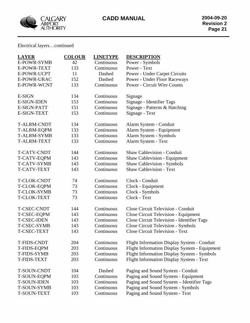
CADD MANUAL
2004-09-20Revision 2
Page 21
Electrical layers…continued LAYER COLOUR LINETYPE DESCRIPTION E-POWR-SYMB 42 Continuous Power - Symbols E-POWR-TEXT 133 Continuous Power - Text E-POWR-UCPT 11 Dashed Power - Under Carpet Circuits E-POWR-URAC 152 Dashed Power - Under Floor Raceways E-POWR-WCNT 133 Continuous Power - Circuit Wire Counts E-SIGN 134 Continuous Signage E-SIGN-IDEN 153 Continuous Signage - Identifier Tags E-SIGN-PATT 151 Continuous Signage - Patterns & Hatching E-SIGN-TEXT 153 Continuous Signage - Text T-ALRM-CNDT 134 Continuous Alarm System - Conduit T-ALRM-EQPM 133 Continuous Alarm System - Equipment T-ALRM-SYMB 133 Continuous Alarm System - Symbols T-ALRM-TEXT 133 Continuous Alarm System - Text T-CATV-CNDT 144 Continuous Shaw Cablevision - Conduit T-CATV-EQPM 143 Continuous Shaw Cablevision - Equipment T-CATV-SYMB 143 Continuous Shaw Cablevision - Symbols T-CATV-TEXT 143 Continuous Shaw Cablevision - Text T-CLOK-CNDT 74 Continuous Clock - Conduit T-CLOK-EQPM 73 Continuous Clock - Equipment T-CLOK-SYMB 73 Continuous Clock - Symbols T-CLOK-TEXT 73 Continuous Clock - Text T-CSEC-CNDT 144 Continuous Close Circuit Television - Conduit T-CSEC-EQPM 143 Continuous Close Circuit Television - Equipment T-CSEC-IDEN 143 Continuous Close Circuit Television - Identifier Tags T-CSEC-SYMB 143 Continuous Close Circuit Television - Symbols T-CSEC-TEXT 143 Continuous Close Circuit Television - Text T-FIDS-CNDT 204 Continuous Flight Information Display System - Conduit T-FIDS-EQPM 203 Continuous Flight Information Display System - Equipment T-FIDS-SYMB 203 Continuous Flight Information Display System - Symbols T-FIDS-TEXT 203 Continuous Flight Information Display System - Text T-SOUN-CNDT 104 Dashed Paging and Sound System - Conduit T-SOUN-EQPM 103 Continuous Paging and Sound System - Equipment T-SOUN-IDEN 103 Continuous Paging and Sound System – Identifier Tags T-SOUN-SYMB 103 Continuous Paging and Sound System - Symbols T-SOUN-TEXT 103 Continuous Paging and Sound System - Text
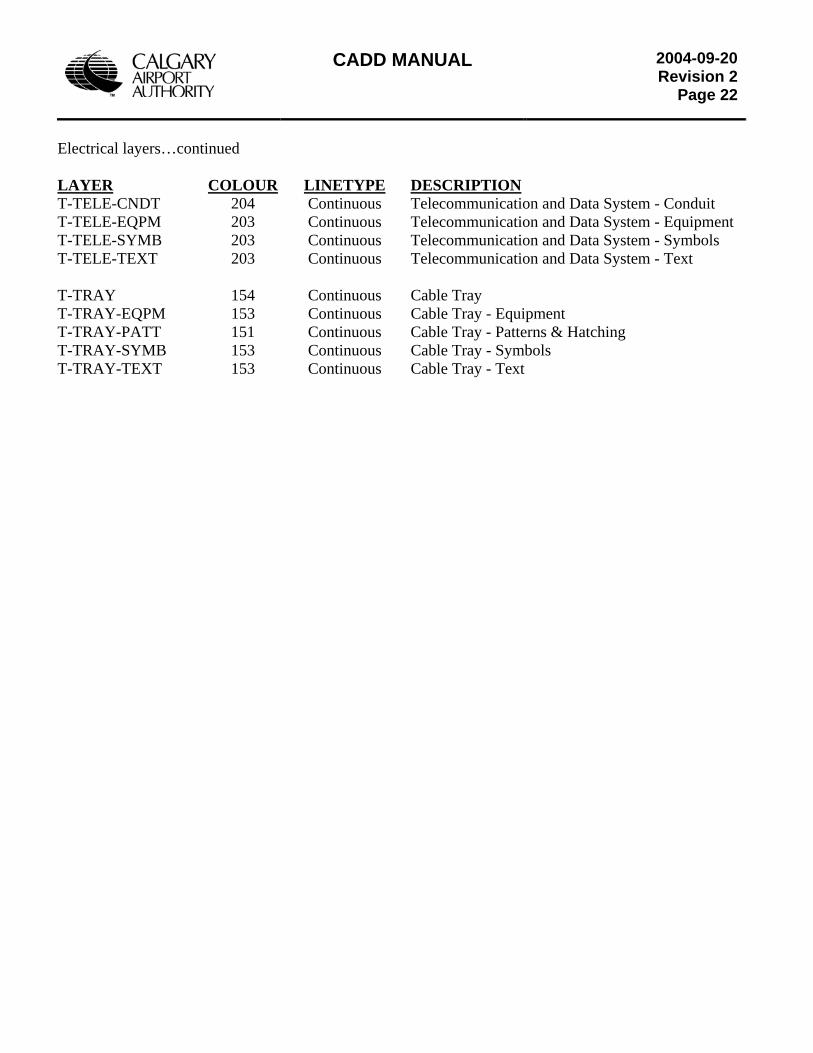
CADD MANUAL
2004-09-20Revision 2
Page 22
Electrical layers…continued LAYER COLOUR LINETYPE DESCRIPTION T-TELE-CNDT 204 Continuous Telecommunication and Data System - Conduit T-TELE-EQPM 203 Continuous Telecommunication and Data System - Equipment T-TELE-SYMB 203 Continuous Telecommunication and Data System - Symbols T-TELE-TEXT 203 Continuous Telecommunication and Data System - Text T-TRAY 154 Continuous Cable Tray T-TRAY-EQPM 153 Continuous Cable Tray - Equipment T-TRAY-PATT 151 Continuous Cable Tray - Patterns & Hatching T-TRAY-SYMB 153 Continuous Cable Tray - Symbols T-TRAY-TEXT 153 Continuous Cable Tray - Text
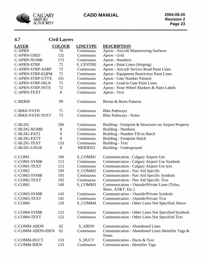
CADD MANUAL
2004-09-20Revision 2
Page 23
4.7 Civil Layers LAYER COLOUR LINETYPE DESCRIPTION C-APRN 76 Continuous Apron - Aircraft Maneuvering Surfaces C-APRN-GRID 132 Continuous Apron - Grid C-APRN-NUMB 173 Continuous Apron - Numbers C-APRN-STRP 72 S_CENTRE Apron - Paint Lines (Striping) C-APRN-STRP-ASRP 72 Continuous Apron - Aircraft Service Road Paint Lines C-APRN-STRP-EQPM 72 Continuous Apron - Equipment Restriction Paint Lines C-APRN-STRP-GTTX 161 Continuous Apron - Gate Number Painted C-APRN-STRP-INLN 72 Continuous Apron - Lead-in Gate Paint Lines C-APRN-STRP-INTX 72 Continuous Apron - Nose Wheel Markers & Paint Labels C-APRN-TEXT 8 Continuous Apron - Text C-BERM 99 Continuous Berms & Berm Patterns C-BIKE-PATH 71 Continuous Bike Pathways C-BIKE-PATH-TEXT 73 Continuous Bike Pathways - Notes C-BLDG 206 Continuous Building - Footprint & Structures on Airport Property C-BLDG-NUMB 8 Continuous Building - Numbers C-BLDG-PAT2 9 Continuous Building - Number Fill-in Hatch C-BLDG-PATT 8 Continuous Building - Footprint Hatch C-BLDG-TEXT 133 Continuous Building - Text C-BLDG-UNGR 8 HIDDEN2 Building - Underground C-COM1 100 S_COMM1 Communication - Calgary Airport Use C-COM1-SYMB 113 Continuous Communication - Calgary Airport Use Symbols C-COM1-TEXT 112 Continuous Communication - Calgary Airport Use text C-COM2 190 S_COMM2 Communication - Nav Aid Specific C-COM2-SYMB 193 Continuous Communication - Nav Aid Specific Symbols C-COM2-TEXT 192 Continuous Communication - Nav Aid Specific Text C-COM3 140 S_COMM3 Communication – Outside/Private Lines (Telus, Shaw, AT&T, Etc.) C-COM3-SYMB 143 Continuous Communication – Outside/Private Symbols C-COM3-TEXT 142 Continuous Communication – Outside/Private Text C-COM4 120 S_COMM4 Communication - Other Lines Not Specified Above C-COM4-SYMB 123 Continuous Communication - Other Lines Not Specified Symbols C-COM4-TEXT 122 Continuous Communication - Other Lines Not Specified Text C-COMM-ABDN 62 S_ABDN Communication - Abandoned Lines C-COMM-ABDN-IDEN 62 Continuous Communication - Abandoned Lines Identifier Tags & Notes C-COMM-DUCT 133 S_DUCT Communication - Ducts & Text C-COMM-IDEN 133 Continuous Communication - Identifier Tags
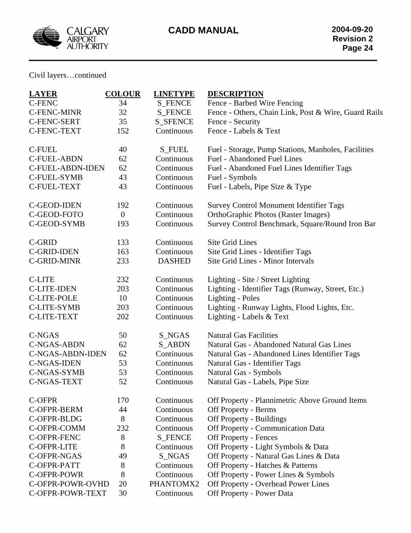
CADD MANUAL
2004-09-20Revision 2
Page 24
Civil layers…continued LAYER COLOUR LINETYPE DESCRIPTION C-FENC 34 S_FENCE Fence - Barbed Wire Fencing C-FENC-MINR 32 S_FENCE Fence - Others, Chain Link, Post & Wire, Guard Rails C-FENC-SERT 35 S_SFENCE Fence - Security C-FENC-TEXT 152 Continuous Fence - Labels & Text C-FUEL 40 S_FUEL Fuel - Storage, Pump Stations, Manholes, Facilities C-FUEL-ABDN 62 Continuous Fuel - Abandoned Fuel Lines C-FUEL-ABDN-IDEN 62 Continuous Fuel - Abandoned Fuel Lines Identifier Tags C-FUEL-SYMB 43 Continuous Fuel - Symbols C-FUEL-TEXT 43 Continuous Fuel - Labels, Pipe Size & Type C-GEOD-IDEN 192 Continuous Survey Control Monument Identifier Tags C-GEOD-FOTO 0 Continuous OrthoGraphic Photos (Raster Images) C-GEOD-SYMB 193 Continuous Survey Control Benchmark, Square/Round Iron Bar C-GRID 133 Continuous Site Grid Lines C-GRID-IDEN 163 Continuous Site Grid Lines - Identifier Tags C-GRID-MINR 233 DASHED Site Grid Lines - Minor Intervals C-LITE 232 Continuous Lighting - Site / Street Lighting C-LITE-IDEN 203 Continuous Lighting - Identifier Tags (Runway, Street, Etc.) C-LITE-POLE 10 Continuous Lighting - Poles C-LITE-SYMB 203 Continuous Lighting - Runway Lights, Flood Lights, Etc. C-LITE-TEXT 202 Continuous Lighting - Labels & Text C-NGAS 50 S_NGAS Natural Gas Facilities C-NGAS-ABDN 62 S_ABDN Natural Gas - Abandoned Natural Gas Lines C-NGAS-ABDN-IDEN 62 Continuous Natural Gas - Abandoned Lines Identifier Tags C-NGAS-IDEN 53 Continuous Natural Gas - Identifier Tags C-NGAS-SYMB 53 Continuous Natural Gas - Symbols C-NGAS-TEXT 52 Continuous Natural Gas - Labels, Pipe Size C-OFPR 170 Continuous Off Property - Plannimetric Above Ground Items C-OFPR-BERM 44 Continuous Off Property - Berms C-OFPR-BLDG 8 Continuous Off Property - Buildings C-OFPR-COMM 232 Continuous Off Property - Communication Data C-OFPR-FENC 8 S_FENCE Off Property - Fences C-OFPR-LITE 8 Continuous Off Property - Light Symbols & Data C-OFPR-NGAS 49 S_NGAS Off Property - Natural Gas Lines & Data C-OFPR-PATT 8 Continuous Off Property - Hatches & Patterns C-OFPR-POWR 8 Continuous Off Property - Power Lines & Symbols C-OFPR-POWR-OVHD 20 PHANTOMX2 Off Property - Overhead Power Lines C-OFPR-POWR-TEXT 30 Continuous Off Property - Power Data
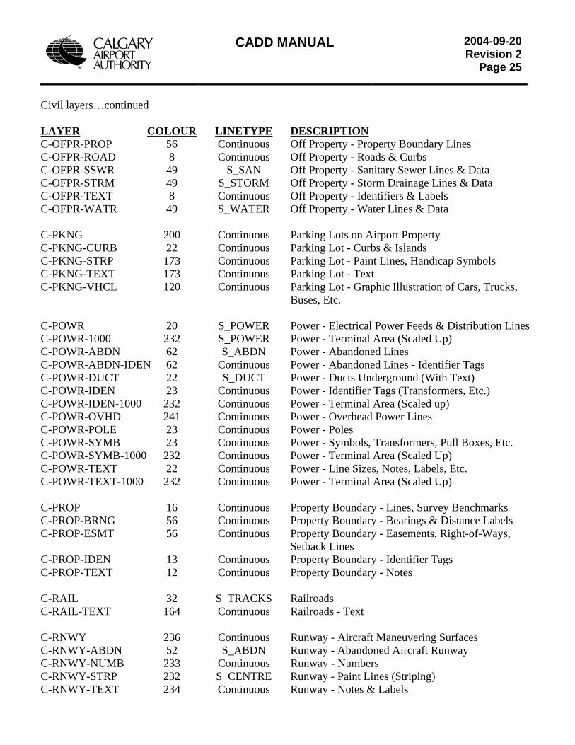
CADD MANUAL
2004-09-20Revision 2
Page 25
Civil layers…continued LAYER COLOUR LINETYPE DESCRIPTION C-OFPR-PROP 56 Continuous Off Property - Property Boundary Lines C-OFPR-ROAD 8 Continuous Off Property - Roads & Curbs C-OFPR-SSWR 49 S_SAN Off Property - Sanitary Sewer Lines & Data C-OFPR-STRM 49 S_STORM Off Property - Storm Drainage Lines & Data C-OFPR-TEXT 8 Continuous Off Property - Identifiers & Labels C-OFPR-WATR 49 S_WATER Off Property - Water Lines & Data C-PKNG 200 Continuous Parking Lots on Airport Property C-PKNG-CURB 22 Continuous Parking Lot - Curbs & Islands C-PKNG-STRP 173 Continuous Parking Lot - Paint Lines, Handicap Symbols C-PKNG-TEXT 173 Continuous Parking Lot - Text C-PKNG-VHCL 120 Continuous Parking Lot - Graphic Illustration of Cars, Trucks, Buses, Etc. C-POWR 20 S_POWER Power - Electrical Power Feeds & Distribution Lines C-POWR-1000 232 S_POWER Power - Terminal Area (Scaled Up) C-POWR-ABDN 62 S_ABDN Power - Abandoned Lines C-POWR-ABDN-IDEN 62 Continuous Power - Abandoned Lines - Identifier Tags C-POWR-DUCT 22 S_DUCT Power - Ducts Underground (With Text) C-POWR-IDEN 23 Continuous Power - Identifier Tags (Transformers, Etc.) C-POWR-IDEN-1000 232 Continuous Power - Terminal Area (Scaled up) C-POWR-OVHD 241 Continuous Power - Overhead Power Lines C-POWR-POLE 23 Continuous Power - Poles C-POWR-SYMB 23 Continuous Power - Symbols, Transformers, Pull Boxes, Etc. C-POWR-SYMB-1000 232 Continuous Power - Terminal Area (Scaled Up) C-POWR-TEXT 22 Continuous Power - Line Sizes, Notes, Labels, Etc. C-POWR-TEXT-1000 232 Continuous Power - Terminal Area (Scaled Up) C-PROP 16 Continuous Property Boundary - Lines, Survey Benchmarks C-PROP-BRNG 56 Continuous Property Boundary - Bearings & Distance Labels C-PROP-ESMT 56 Continuous Property Boundary - Easements, Right-of-Ways, Setback Lines C-PROP-IDEN 13 Continuous Property Boundary - Identifier Tags C-PROP-TEXT 12 Continuous Property Boundary - Notes C-RAIL 32 S_TRACKS Railroads C-RAIL-TEXT 164 Continuous Railroads - Text C-RNWY 236 Continuous Runway - Aircraft Maneuvering Surfaces C-RNWY-ABDN 52 S_ABDN Runway - Abandoned Aircraft Runway C-RNWY-NUMB 233 Continuous Runway - Numbers C-RNWY-STRP 232 S_CENTRE Runway - Paint Lines (Striping) C-RNWY-TEXT 234 Continuous Runway - Notes & Labels
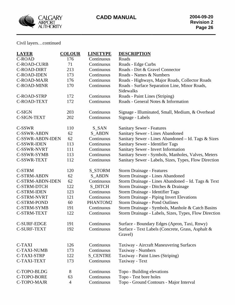
CADD MANUAL
2004-09-20Revision 2
Page 26
Civil layers…continued LAYER COLOUR LINETYPE DESCRIPTION C-ROAD 176 Continuous Roads C-ROAD-CURB 71 Continuous Roads - Edge Curbs C-ROAD-DIRT 213 Continuous Roads - Dirt & Gravel Connector C-ROAD-IDEN 173 Continuous Roads - Names & Numbers C-ROAD-MAJR 176 Continuous Roads - Highways, Major Roads, Collector Roads C-ROAD-MINR 170 Continuous Roads - Surface Separation Line, Minor Roads, Sidewalks C-ROAD-STRP 172 Continuous Roads - Paint Lines (Striping) C-ROAD-TEXT 172 Continuous Roads - General Notes & Information C-SIGN 203 Continuous Signage - Illuminated, Small, Medium, & Overhead C-SIGN-TEXT 202 Continuous Signage - Labels C-SSWR 110 S_SAN Sanitary Sewer - Features C-SSWR-ABDN 62 S_ABDN Sanitary Sewer - Lines Abandoned C-SSWR-ABDN-IDEN 62 Continuous Sanitary Sewer - Lines Abandoned – Id. Tags & Sizes C-SSWR-IDEN 113 Continuous Sanitary Sewer - Identifier Tags C-SSWR-NVRT 111 Continuous Sanitary Sewer - Invert Information C-SSWR-SYMB 113 Continuous Sanitary Sewer - Symbols, Manholes, Valves, Meters C-SSWR-TEXT 112 Continuous Sanitary Sewer - Labels, Sizes, Types, Flow Direction C-STRM 120 S_STORM Storm Drainage - Features C-STRM-ABDN 62 S_ABDN Storm Drainage - Lines Abandoned C-STRM-ABDN-IDEN 62 Continuous Storm Drainage - Lines Abandoned – Id. Tags & Text C-STRM-DTCH 122 S_DITCH Storm Drainage - Ditches & Drainage C-STRM-IDEN 123 Continuous Storm Drainage - Identifier Tags C-STRM-NVRT 121 Continuous Storm Drainage - Piping Invert Elevations C-STRM-POND 60 PHANTOM2 Storm Drainage - Pond Outlines C-STRM-SYMB 191 Continuous Storm Drainage - Symbols, Manhole & Catch Basins C-STRM-TEXT 122 Continuous Storm Drainage - Labels, Sizes, Types, Flow Direction C-SURF-EDGE 191 Continuous Surface - Boundary Edges (Apron, Taxi, Rnwy) C-SURF-TEXT 192 Continuous Surface - Text Labels (Concrete, Grass, Asphalt & Gravel) C-TAXI 126 Continuous Taxiway - Aircraft Maneuvering Surfaces C-TAXI-NUMB 173 Continuous Taxiway - Numbers C-TAXI-STRP 122 S_CENTRE Taxiway - Paint Lines (Striping) C-TAXI-TEXT 173 Continuous Taxiway - Text C-TOPO-BLDG 8 Continuous Topo - Building elevations C-TOPO-BORE 63 Continuous Topo - Test bore holes C-TOPO-MAJR 4 Continuous Topo - Ground Contours - Major Interval
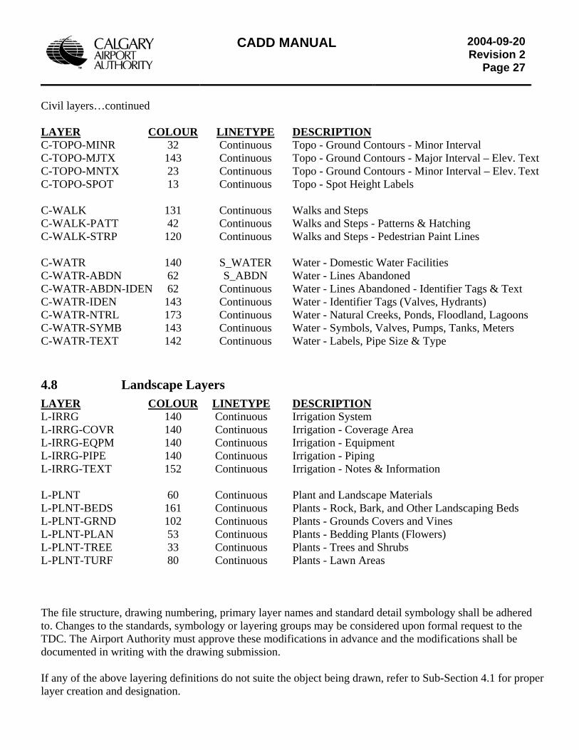
CADD MANUAL
2004-09-20Revision 2
Page 27
Civil layers…continued LAYER COLOUR LINETYPE DESCRIPTION C-TOPO-MINR 32 Continuous Topo - Ground Contours - Minor Interval C-TOPO-MJTX 143 Continuous Topo - Ground Contours - Major Interval – Elev. Text C-TOPO-MNTX 23 Continuous Topo - Ground Contours - Minor Interval – Elev. Text C-TOPO-SPOT 13 Continuous Topo - Spot Height Labels C-WALK 131 Continuous Walks and Steps C-WALK-PATT 42 Continuous Walks and Steps - Patterns & Hatching C-WALK-STRP 120 Continuous Walks and Steps - Pedestrian Paint Lines C-WATR 140 S_WATER Water - Domestic Water Facilities C-WATR-ABDN 62 S_ABDN Water - Lines Abandoned C-WATR-ABDN-IDEN 62 Continuous Water - Lines Abandoned - Identifier Tags & Text C-WATR-IDEN 143 Continuous Water - Identifier Tags (Valves, Hydrants) C-WATR-NTRL 173 Continuous Water - Natural Creeks, Ponds, Floodland, Lagoons C-WATR-SYMB 143 Continuous Water - Symbols, Valves, Pumps, Tanks, Meters C-WATR-TEXT 142 Continuous Water - Labels, Pipe Size & Type
4.8 Landscape Layers LAYER COLOUR LINETYPE DESCRIPTION L-IRRG 140 Continuous Irrigation System L-IRRG-COVR 140 Continuous Irrigation - Coverage Area L-IRRG-EQPM 140 Continuous Irrigation - Equipment L-IRRG-PIPE 140 Continuous Irrigation - Piping L-IRRG-TEXT 152 Continuous Irrigation - Notes & Information L-PLNT 60 Continuous Plant and Landscape Materials L-PLNT-BEDS 161 Continuous Plants - Rock, Bark, and Other Landscaping Beds L-PLNT-GRND 102 Continuous Plants - Grounds Covers and Vines L-PLNT-PLAN 53 Continuous Plants - Bedding Plants (Flowers) L-PLNT-TREE 33 Continuous Plants - Trees and Shrubs L-PLNT-TURF 80 Continuous Plants - Lawn Areas The file structure, drawing numbering, primary layer names and standard detail symbology shall be adhered to. Changes to the standards, symbology or layering groups may be considered upon formal request to the TDC. The Airport Authority must approve these modifications in advance and the modifications shall be documented in writing with the drawing submission. If any of the above layering definitions do not suite the object being drawn, refer to Sub-Section 4.1 for proper layer creation and designation.
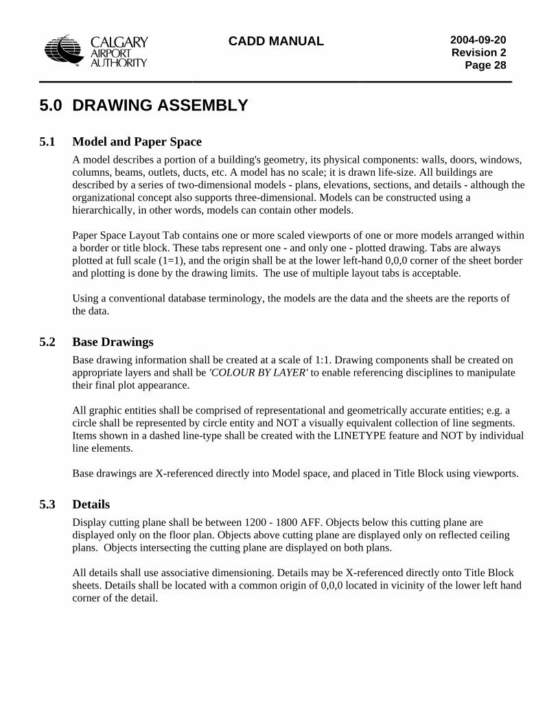
CADD MANUAL
2004-09-20Revision 2
Page 28
5.0 DRAWING ASSEMBLY
5.1 Model and Paper Space A model describes a portion of a building's geometry, its physical components: walls, doors, windows, columns, beams, outlets, ducts, etc. A model has no scale; it is drawn life-size. All buildings are described by a series of two-dimensional models - plans, elevations, sections, and details - although the organizational concept also supports three-dimensional. Models can be constructed using a hierarchically, in other words, models can contain other models. Paper Space Layout Tab contains one or more scaled viewports of one or more models arranged within a border or title block. These tabs represent one - and only one - plotted drawing. Tabs are always plotted at full scale (1=1), and the origin shall be at the lower left-hand 0,0,0 corner of the sheet border and plotting is done by the drawing limits. The use of multiple layout tabs is acceptable. Using a conventional database terminology, the models are the data and the sheets are the reports of the data.
5.2 Base Drawings Base drawing information shall be created at a scale of 1:1. Drawing components shall be created on appropriate layers and shall be 'COLOUR BY LAYER' to enable referencing disciplines to manipulate their final plot appearance. All graphic entities shall be comprised of representational and geometrically accurate entities; e.g. a circle shall be represented by circle entity and NOT a visually equivalent collection of line segments. Items shown in a dashed line-type shall be created with the LINETYPE feature and NOT by individual line elements. Base drawings are X-referenced directly into Model space, and placed in Title Block using viewports.
5.3 Details Display cutting plane shall be between 1200 - 1800 AFF. Objects below this cutting plane are displayed only on the floor plan. Objects above cutting plane are displayed only on reflected ceiling plans. Objects intersecting the cutting plane are displayed on both plans. All details shall use associative dimensioning. Details may be X-referenced directly onto Title Block sheets. Details shall be located with a common origin of 0,0,0 located in vicinity of the lower left hand corner of the detail.
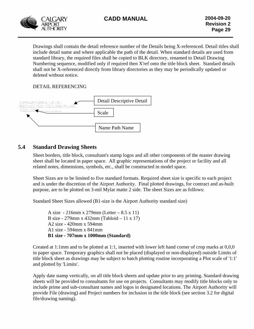
CADD MANUAL
2004-09-20Revision 2
Page 29
Drawings shall contain the detail reference number of the Details being X-referenced. Detail titles shall include detail name and where applicable the path of the detail. When standard details are used from standard library, the required files shall be copied to BLK directory, renamed to Detail Drawing Numbering sequence, modified only if required then X'ref onto the title block sheet. Standard details shall not be X-referenced directly from library directories as they may be periodically updated or deleted without notice. DETAIL REFERENCING
5.4 Standard Drawing SheetsSheet borders, title block, consusheet shall be located in paper srelated notes, dimensions, symb Sheet Sizes are to be limited to and is under the discretion of thpurpose, are to be plotted on 3- Standard Sheet Sizes allowed (B A size - 216mm x 279m B size - 279mm x 432m A2 size - 420mm x 594 A1 size - 594mm x 841
B1 size - 707mm x 100 Created at 1:1mm and to be ploin paper space. Temporary graptitle block sheet as drawings maand plotted by 'Limits'. Apply date stamp vertically, onsheets will be provided to consuinclude prime and sub-consultaprovide File (drawing) and Projfile/drawing naming).
Scale
e
m
mm0
n
Name Path Nam
Detail Descriptive Detail
ltant's stamp logos and all other components of the master drawing pace. All graphic representations of the project or facility and all ols, etc., shall be constructed in model space.
five standard formats. Required sheet size is specific to each project e Airport Authority. Final plotted drawings, for contract and as-built
il Mylar matte 2 side. The sheet Sizes are as follows:
1-size is the Airport Authority standard size)
m (Letter – 8.5 x 11) m (Tabloid – 11 x 17)
m m mm (Standard)
tted at 1:1, inserted with lower left hand corner of crop marks at 0,0,0 hics shall not be placed (displayed or non-displayed) outside Limits of y be subject to batch plotting routine incorporating a Plot scale of '1:1'
all title block sheets and update prior to any printing. Standard drawing ltants for use on projects. Consultants may modify title blocks only to t names and logos in designated locations. The Airport Authority will
ect numbers for inclusion in the title block (see section 3.2 for digital
CADD MANUAL
2004-09-20Revision 2
Page 30
5.5 Dimensioning All dimensions shown in the project submittals shall be fully associative and placed on appropriate layers. Dimension definition points should be located with an appropriate Object Snap (End Point, Mid Point, etc.) or otherwise located precisely on the project geometry. Manual input of dimension Text or Non-associative dimensions are NOT acceptable in submittals to the Airport Authority Note: Due to the different units used in Building (millimeters) and Site drawings (metres) different dim styles are used. The following is an example of a Site - Meter (millimeters settings will be different).
Dimension Styles are included in template files. They include CAA_MS1 (model space dimensioning), and CAA_PS1 (paper space dimensioning). All settings are inclusive in the style. If unable to use one of the above, start a new style and dimension as follows: Dimension Variables: Dimension Lines: spacing = 10; colour >by layer Extension Lines: extension = 2; origin offset = 2; colour >by layer. Architectural Arrowheads: users arrow = Dimtick; size 1.5 Engineering Arrowheads: Closed filled = size 1.5 Scale: Set to Drawing Scale Horizontal Justification = centred. Vertical Justification = above. Primary Units = decimal; precision 0.000
If dimensions are placed in paper space ensure to change “dimlfac” to the scale of the viewport.
5.6 Text Styles Text used on Calgary Airport Authority projects by both in-house design team and external consultants shall follow the styles listed below. The standard notation Text size shall be 2.5mm, (2.0mm will be allowed) to facilitate one half-scale plotting. Note: Due to the different units used in Building (millimeters) and Site drawings (metres) different Text styles are used. The following is an example of a Building - millimeters (meters settings will be different).
General Notation - plans and details Style XFine, Font CAA_Arch, Size 200mm OR Style XFine, Font CAA_Eng, Size 200mm Style Fine, Font CAA_Arch, Size 250mm Style Fine, Font CAA_Eng, Size 250mm Style Medium, Font CAA_Arch, Size 300mm Style Medium, Font CAA_Eng, Size 300mm Style Large, Font CAA_Arch, Size 400mm Style Large, Font CAA_Eng, Size 400mm Detail Titles - as predefined attributes Miscellaneous Symbols - as predefined attributes Title Blocks - as predefined attributes
Copies of all fonts and Symbols are available from the Airport Authority for external consultant use and are supplied on Airport Authority Standards CD-ROM.
CADD MANUAL
2004-09-20Revision 2
Page 31
Common Airport Authority Fonts
5.7 Line Styles The line styles used by the Airport Authority are named CAA.LIN and contain custom line styles used within the Building and Site record drawings. Line style names starting with “B” are used in the building; names starting with “S” are used in the Site. The remainder of the name describes the type of line. Example: S_SFENCE (Site Security Fence) or B_NGAS (Building Natural Gas)
Line styles are based on the ACADISO.LIN (AutoCAD metric) file. DO NOT USE IMPERIAL LINETYPES OR LINE STYLES.
5.8 Template Drawing Files Template drawing files and symbols provided by the Airport Authority shall be utilized. These may include but not be limited to the following: • Typical Title Sheets • Formatted Drawing Files • Drawing Symbology and Other Blocks • Dimension Styles, Text Styles • Pre-built Airport Authority Layers
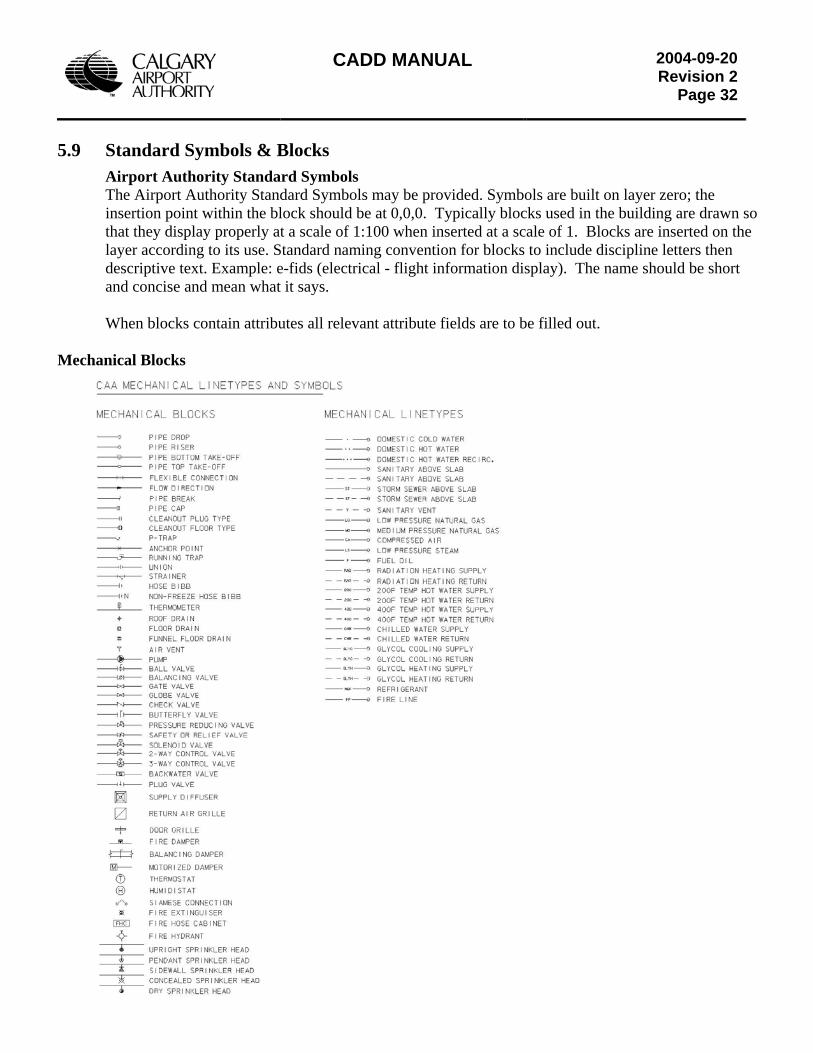
CADD MANUAL
2004-09-20Revision 2
Page 32
5.9 Standard Symbols & Blocks
Airport Authority Standard Symbols The Airport Authority Standard Symbols may be provided. Symbols are built on layer zero; the insertion point within the block should be at 0,0,0. Typically blocks used in the building are drawn so that they display properly at a scale of 1:100 when inserted at a scale of 1. Blocks are inserted on the layer according to its use. Standard naming convention for blocks to include discipline letters then descriptive text. Example: e-fids (electrical - flight information display). The name should be short and concise and mean what it says. When blocks contain attributes all relevant attribute fields are to be filled out.
Mechanical Blocks
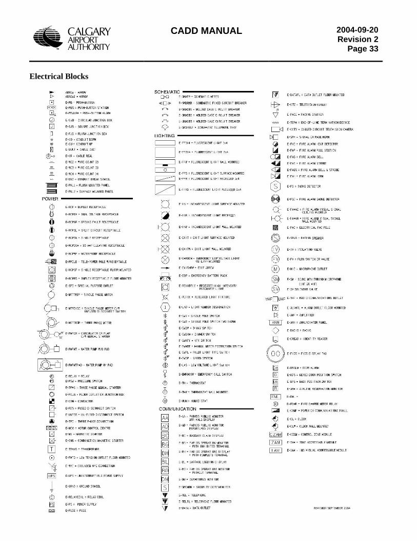
CADD MANUAL
2004-09-20Revision 2
Page 33
Electrical Blocks
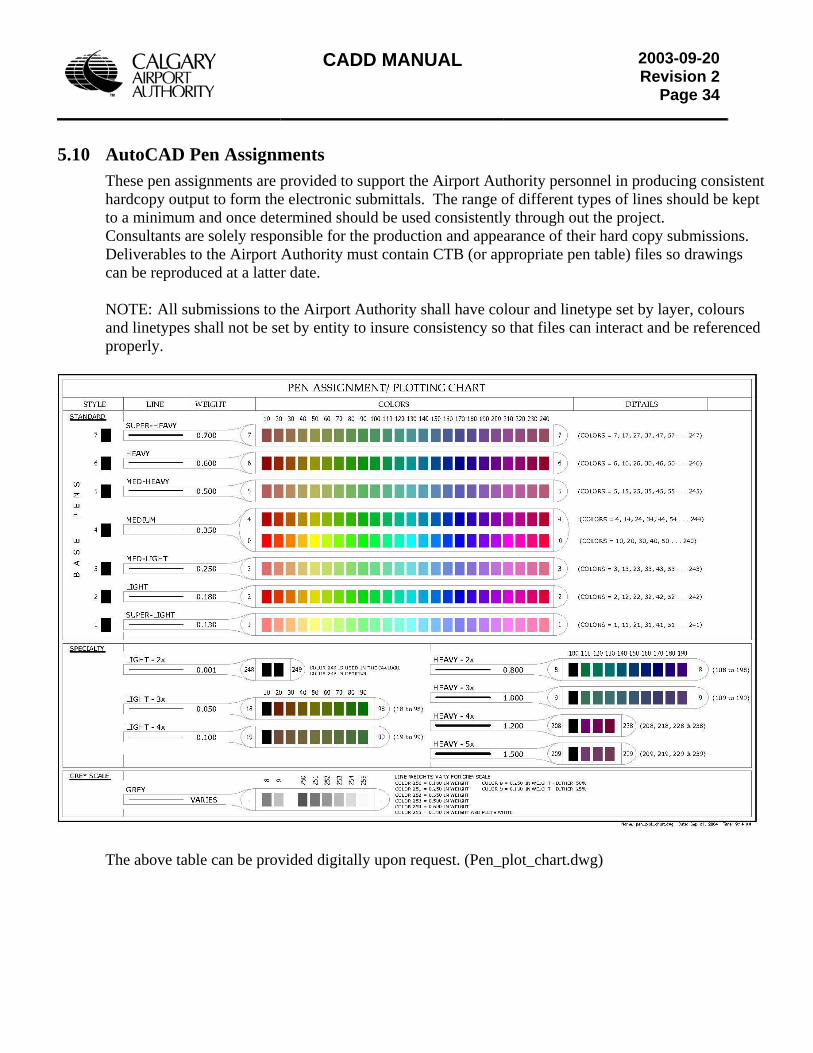
CADD MANUAL
2003-09-20Revision 2
Page 34
5.10 AutoCAD Pen Assignments These pen assignments are provided to support the Airport Authority personnel in producing consistent hardcopy output to form the electronic submittals. The range of different types of lines should be kept to a minimum and once determined should be used consistently through out the project. Consultants are solely responsible for the production and appearance of their hard copy submissions. Deliverables to the Airport Authority must contain CTB (or appropriate pen table) files so drawings can be reproduced at a latter date.
NOTE: All submissions to the Airport Authority shall have colour and linetype set by layer, colours and linetypes shall not be set by entity to insure consistency so that files can interact and be referenced properly.
The above table can be provided digitally upon request. (Pen_plot_chart.dwg)
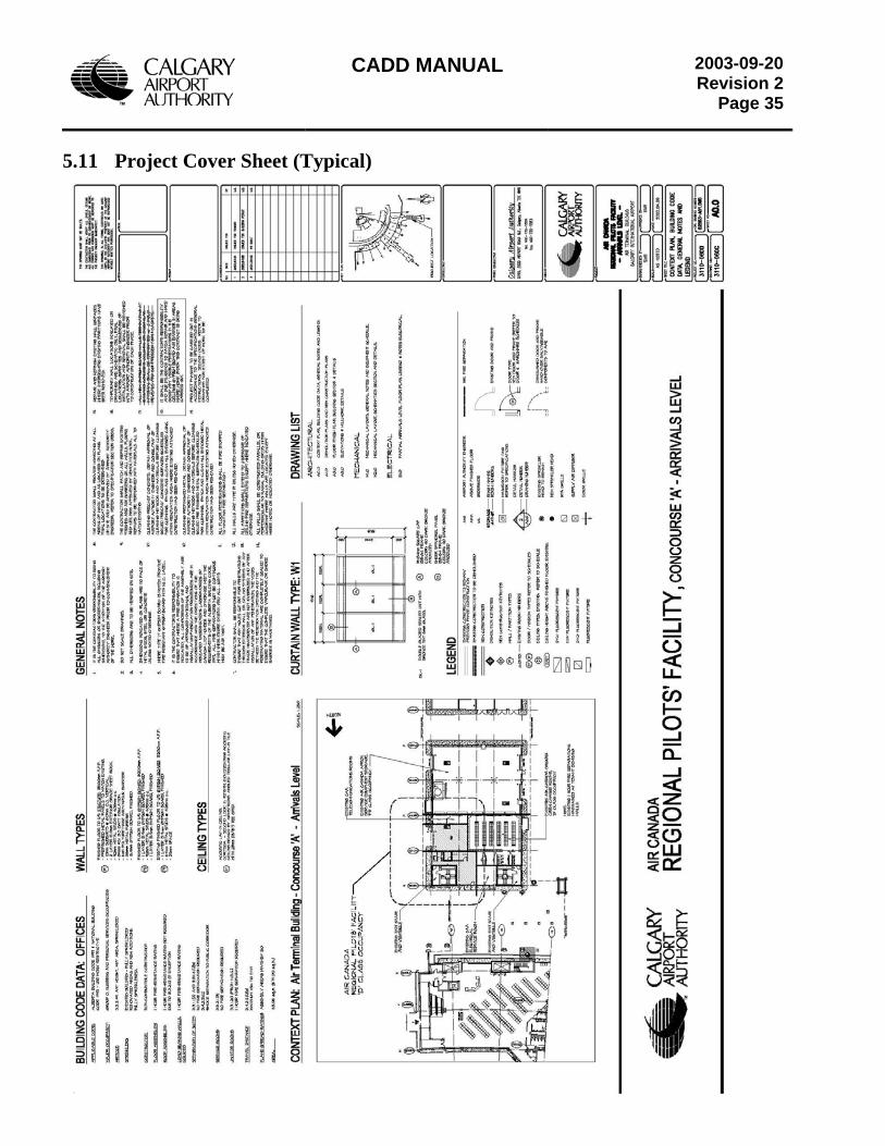
CADD MANUAL
2003-09-20Revision 2
Page 35
5.11 Project Cover Sheet (Typical)
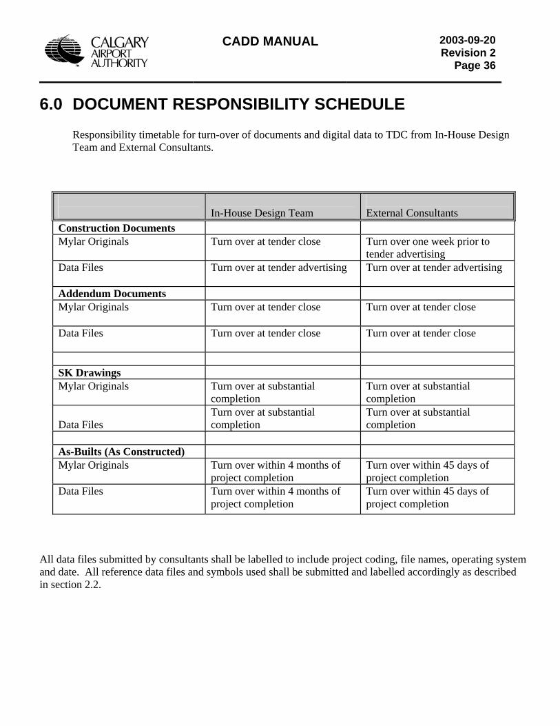
CADD MANUAL
2003-09-20Revision 2
Page 36
6.0 DOCUMENT RESPONSIBILITY SCHEDULE
Responsibility timetable for turn-over of documents and digital data to TDC from In-House Design Team and External Consultants.
In-House Design Team
External Consultants
Construction Documents Mylar Originals Turn over at tender close Turn over one week prior to
tender advertising Data Files Turn over at tender advertising Turn over at tender advertising
Addendum Documents Mylar Originals Turn over at tender close Turn over at tender close
Data Files Turn over at tender close Turn over at tender close
SK Drawings Mylar Originals Turn over at substantial
completion Turn over at substantial completion
Data Files
Turn over at substantial completion
Turn over at substantial completion
As-Builts (As Constructed) Mylar Originals Turn over within 4 months of
project completion Turn over within 45 days of project completion
Data Files Turn over within 4 months of project completion
Turn over within 45 days of project completion
All data files submitted by consultants shall be labelled to include project coding, file names, operating system and date. All reference data files and symbols used shall be submitted and labelled accordingly as described in section 2.2.
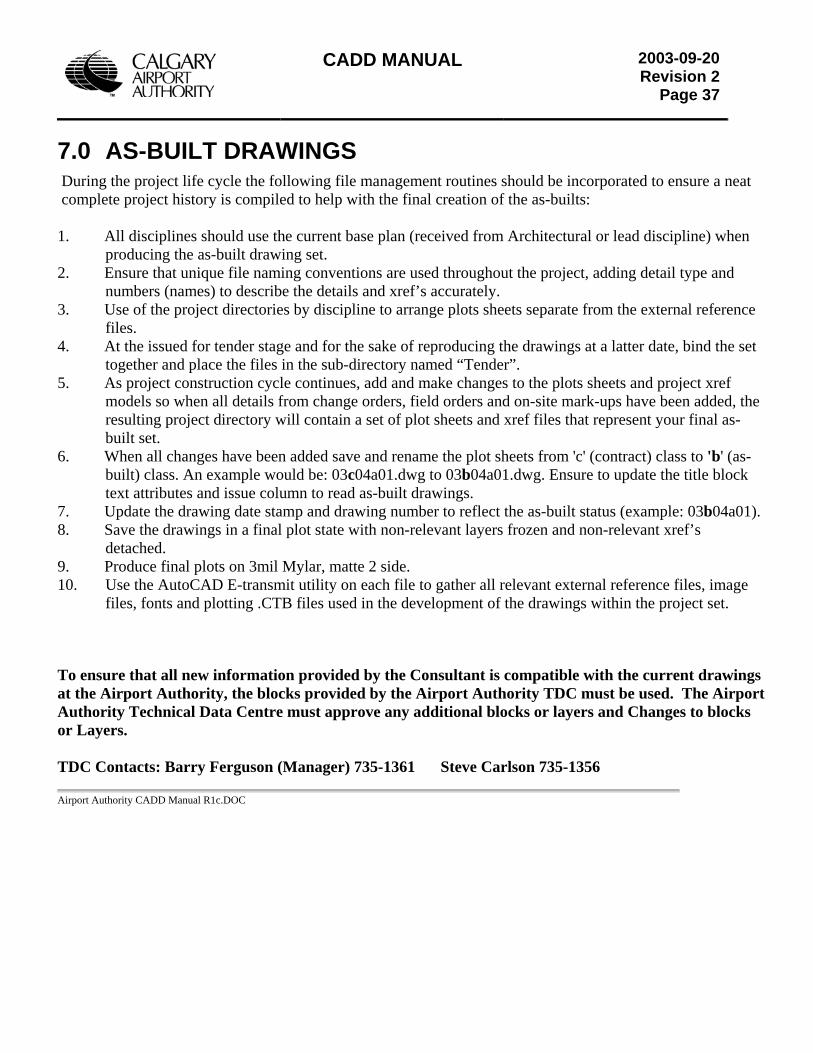
CADD MANUAL
2003-09-20Revision 2
Page 37
7.0 AS-BUILT DRAWINGS During the project life cycle the following file management routines should be incorporated to ensure a neat complete project history is compiled to help with the final creation of the as-builts: 1. All disciplines should use the current base plan (received from Architectural or lead discipline) when
producing the as-built drawing set. 2. Ensure that unique file naming conventions are used throughout the project, adding detail type and
numbers (names) to describe the details and xref’s accurately. 3. Use of the project directories by discipline to arrange plots sheets separate from the external reference
files. 4. At the issued for tender stage and for the sake of reproducing the drawings at a latter date, bind the set
together and place the files in the sub-directory named “Tender”. 5. As project construction cycle continues, add and make changes to the plots sheets and project xref
models so when all details from change orders, field orders and on-site mark-ups have been added, the resulting project directory will contain a set of plot sheets and xref files that represent your final as-built set.
6. When all changes have been added save and rename the plot sheets from 'c' (contract) class to 'b' (as-built) class. An example would be: 03c04a01.dwg to 03b04a01.dwg. Ensure to update the title block text attributes and issue column to read as-built drawings.
7. Update the drawing date stamp and drawing number to reflect the as-built status (example: 03b04a01). 8. Save the drawings in a final plot state with non-relevant layers frozen and non-relevant xref’s
detached. 9. Produce final plots on 3mil Mylar, matte 2 side. 10. Use the AutoCAD E-transmit utility on each file to gather all relevant external reference files, image
files, fonts and plotting .CTB files used in the development of the drawings within the project set. To ensure that all new information provided by the Consultant is compatible with the current drawings at the Airport Authority, the blocks provided by the Airport Authority TDC must be used. The Airport Authority Technical Data Centre must approve any additional blocks or layers and Changes to blocks or Layers. TDC Contacts: Barry Ferguson (Manager) 735-1361 Steve Carlson 735-1356 Airport Authority CADD Manual R1c.DOC
Appendix “D” Telecommunication Services Request
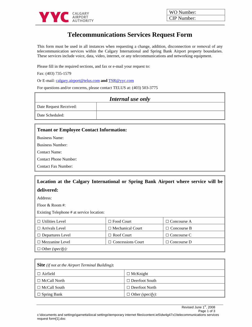
WO Number: CIP Number:
Revised June 1st, 2008 Page 1 of 3 c:\documents and settings\garnetta\local settings\temporary internet files\content.ie5\dw4g47x1\telecommunications services request form[1].doc
Telecommunications Services Request Form This form must be used in all instances when requesting a change, addition, disconnection or removal of any telecommunication services within the Calgary International and Spring Bank Airport property boundaries. These services include voice, data, video, internet, or any telecommunications and networking equipment. Please fill in the required sections, and fax or e-mail your request to:
Fax: (403) 735-1579
Or E-mail: [email protected] and [email protected]
For questions and/or concerns, please contact TELUS at: (403) 503-3775
Internal use only Date Request Received: Date Scheduled:
Tenant or Employee Contact Information: Business Name:
Business Number:
Contact Name:
Contact Phone Number:
Contact Fax Number:
Location at the Calgary International or Spring Bank Airport where service will be
delivered: Address:
Floor & Room #:
Existing Telephone # at service location: □ Utilities Level □ Food Court □ Concourse A
□ Arrivals Level □ Mechanical Court □ Concourse B
□ Departures Level □ Roof Court □ Concourse C
□ Mezzanine Level □ Concessions Court □ Concourse D
□ Other (specify):
Site (if not at the Airport Terminal Building):
□ Airfield □ McKnight
□ McCall North □ Deerfoot South
□ McCall South □ Deerfoot North
□ Spring Bank □ Other (specify):
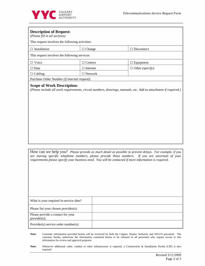
Telecommunications Service Request Form
Revised 3/11/2009 Page 2 of 3
Description of Request: (Please fill in all sections)
This request involves the following activities: □ Installation □ Change □ Disconnect
This request involves the following services:
□ Voice □ Centrex □ Equipment
□ Data □ Internet
□ Cabling □ Network
□ Other (specify):
Purchase Order Number (if internal request):
Scope of Work Description: (Please include all work requirements, circuit numbers, drawings, manuals, etc. Add as attachment if required.)
How can we help you? Please provide as much detail as possible to prevent delays. For example, if you are moving specific telephone numbers, please provide those numbers. If you are uncertain of your requirements please specify your business need. You will be contacted if more information is required.
What is your required in-service date?
Please list your chosen provider(s):
Please provide a contact for your provider(s):
Provider(s) service order number(s):
Note: Customer information provided herein will be reviewed by both the Calgary Airport Authority and TELUS personnel. The
customer hereby authorizes the information contained herein to be released to all personnel who require access to this information for review and approval purposes
Note: Whenever additional cable, conduit or other infrastructure is required, a Construction & Installation Permit (CIP) is also
required.
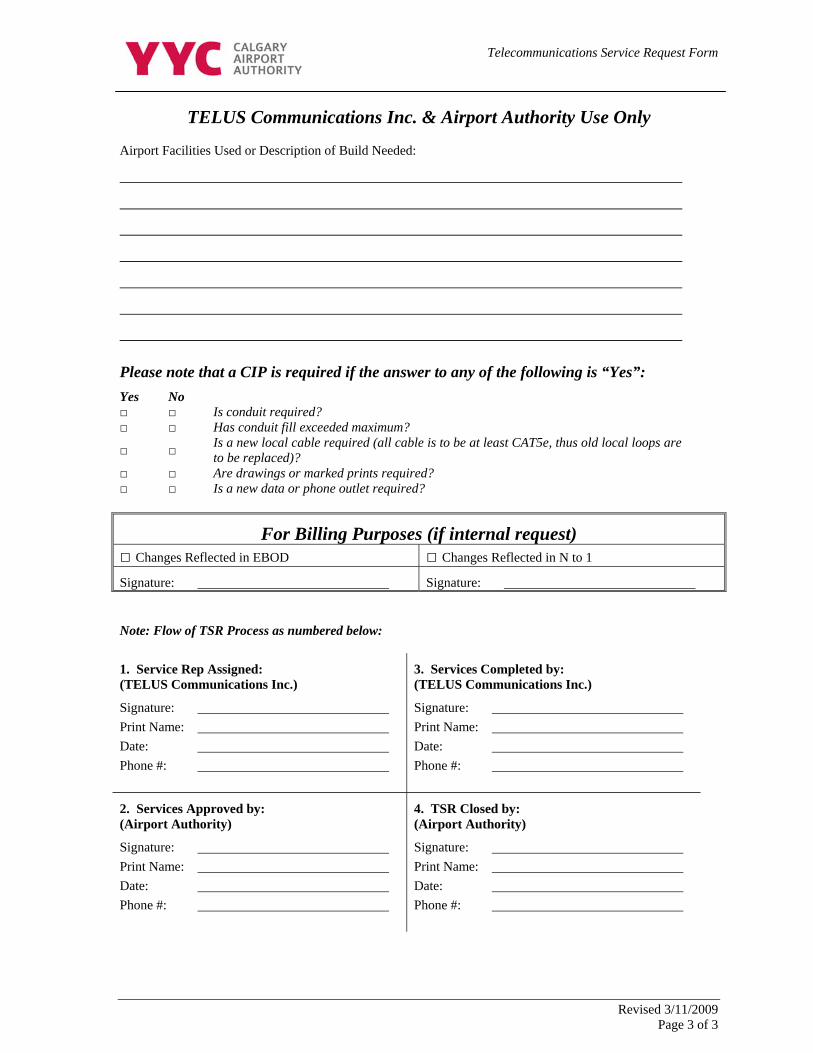
Telecommunications Service Request Form
Revised 3/11/2009 Page 3 of 3
TELUS Communications Inc. & Airport Authority Use Only Airport Facilities Used or Description of Build Needed:
Please note that a CIP is required if the answer to any of the following is “Yes”: Yes No □ □ Is conduit required? □ □ Has conduit fill exceeded maximum?
□ □ Is a new local cable required (all cable is to be at least CAT5e, thus old local loops are to be replaced)?
□ □ Are drawings or marked prints required? □ □ Is a new data or phone outlet required?
For Billing Purposes (if internal request) □ Changes Reflected in EBOD □ Changes Reflected in N to 1 Signature: Signature: Note: Flow of TSR Process as numbered below:
1. Service Rep Assigned: (TELUS Communications Inc.)
Signature: Print Name: Date: Phone #:
3. Services Completed by: (TELUS Communications Inc.)
Signature: Print Name: Date: Phone #:
2. Services Approved by: (Airport Authority)
Signature: Print Name: Date: Phone #:
4. TSR Closed by: (Airport Authority)
Signature: Print Name: Date: Phone #:
Appendix “E” Building Code Requirements for Tenant Occupancies
Calgary International Airport Air terminal Building
Building Code Requirements For Tenant Occupancies
The following excerpts and interpretations from the Alberta Building Code 2006 are included as a quick reference for your information only; they do not supercede the Alberta Building Code 2006. It is the responsibility of the tenant, or the tenant’s design professional, to read and ensure compliance with the Alberta Building Code 2006 and all other Codes application to your specific project.
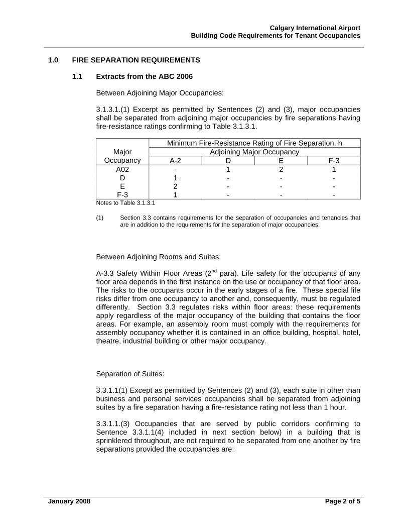
Calgary International Airport Building Code Requirements for Tenant Occupancies
January 2008 Page 2 of 5
1.0 FIRE SEPARATION REQUIREMENTS
1.1 Extracts from the ABC 2006
Between Adjoining Major Occupancies:
3.1.3.1.(1) Excerpt as permitted by Sentences (2) and (3), major occupancies shall be separated from adjoining major occupancies by fire separations having fire-resistance ratings confirming to Table 3.1.3.1.
Minimum Fire-Resistance Rating of Fire Separation, h Adjoining Major Occupancy Major
Occupancy A-2 D E F-3 A02 - 1 2 1 D 1 - - - E 2 - - -
F-3 1 - - - Notes to Table 3.1.3.1
(1) Section 3.3 contains requirements for the separation of occupancies and tenancies that are in addition to the requirements for the separation of major occupancies.
Between Adjoining Rooms and Suites:
A-3.3 Safety Within Floor Areas (2nd para). Life safety for the occupants of any floor area depends in the first instance on the use or occupancy of that floor area. The risks to the occupants occur in the early stages of a fire. These special life risks differ from one occupancy to another and, consequently, must be regulated differently. Section 3.3 regulates risks within floor areas: these requirements apply regardless of the major occupancy of the building that contains the floor areas. For example, an assembly room must comply with the requirements for assembly occupancy whether it is contained in an office building, hospital, hotel, theatre, industrial building or other major occupancy.
Separation of Suites:
3.3.1.1(1) Except as permitted by Sentences (2) and (3), each suite in other than business and personal services occupancies shall be separated from adjoining suites by a fire separation having a fire-resistance rating not less than 1 hour.
3.3.1.1.(3) Occupancies that are served by public corridors confirming to Sentence 3.3.1.1(4) included in next section below) in a building that is sprinklered throughout, are not required to be separated from one another by fire separations provided the occupancies are:
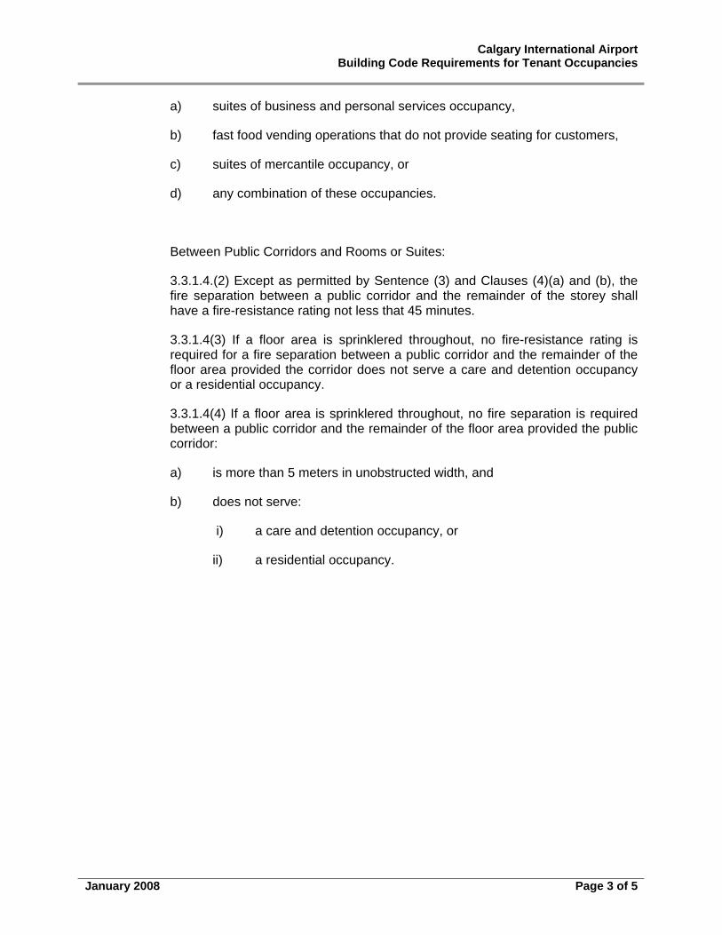
Calgary International Airport Building Code Requirements for Tenant Occupancies
January 2008 Page 3 of 5
a) suites of business and personal services occupancy,
b) fast food vending operations that do not provide seating for customers,
c) suites of mercantile occupancy, or
d) any combination of these occupancies.
Between Public Corridors and Rooms or Suites:
3.3.1.4.(2) Except as permitted by Sentence (3) and Clauses (4)(a) and (b), the fire separation between a public corridor and the remainder of the storey shall have a fire-resistance rating not less that 45 minutes.
3.3.1.4(3) If a floor area is sprinklered throughout, no fire-resistance rating is required for a fire separation between a public corridor and the remainder of the floor area provided the corridor does not serve a care and detention occupancy or a residential occupancy.
3.3.1.4(4) If a floor area is sprinklered throughout, no fire separation is required between a public corridor and the remainder of the floor area provided the public corridor:
a) is more than 5 meters in unobstructed width, and
b) does not serve:
i) a care and detention occupancy, or
ii) a residential occupancy.
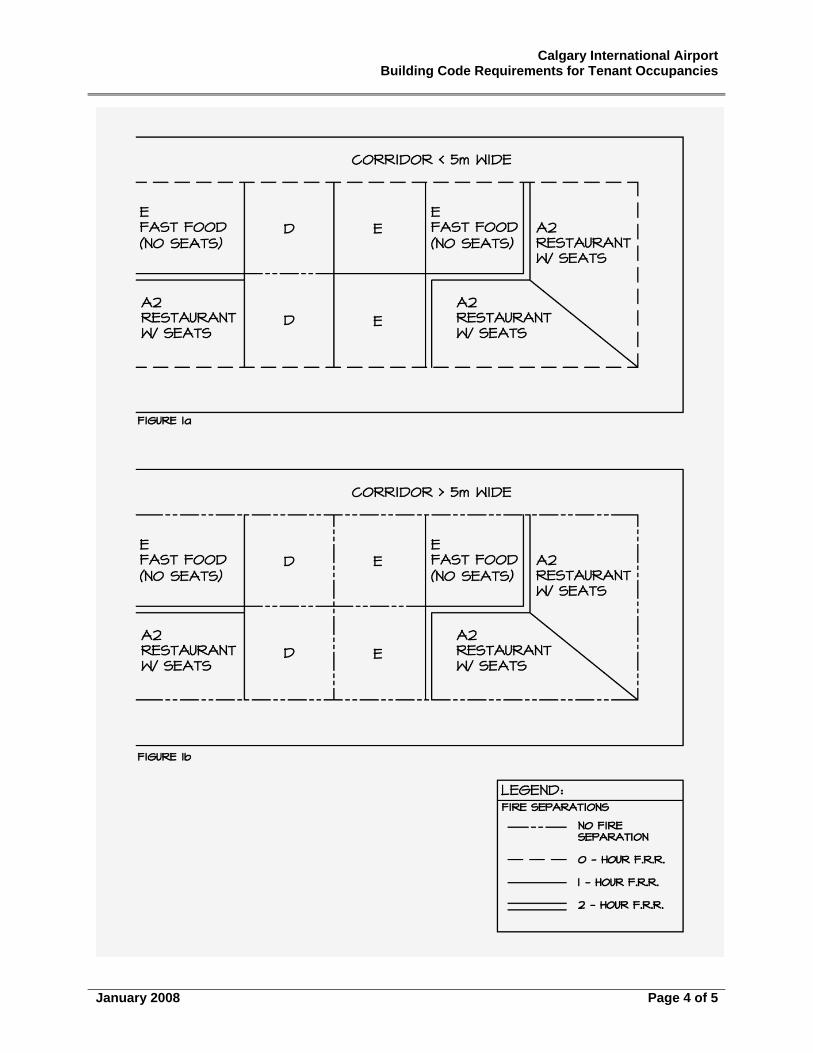
Calgary International Airport Building Code Requirements for Tenant Occupancies
January 2008 Page 4 of 5
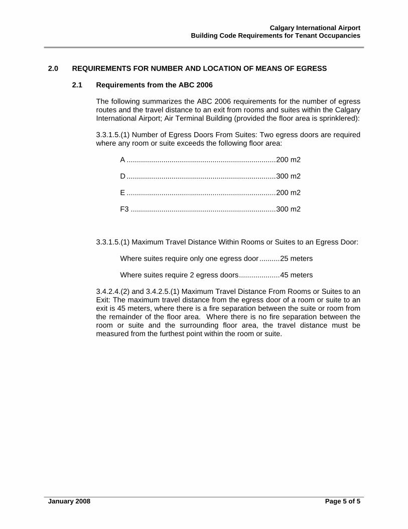
Calgary International Airport Building Code Requirements for Tenant Occupancies
January 2008 Page 5 of 5
2.0 REQUIREMENTS FOR NUMBER AND LOCATION OF MEANS OF EGRESS
2.1 Requirements from the ABC 2006
The following summarizes the ABC 2006 requirements for the number of egress routes and the travel distance to an exit from rooms and suites within the Calgary International Airport; Air Terminal Building (provided the floor area is sprinklered):
3.3.1.5.(1) Number of Egress Doors From Suites: Two egress doors are required where any room or suite exceeds the following floor area:
A .........................................................................200 m2
D .........................................................................300 m2
E .........................................................................200 m2
F3 .......................................................................300 m2
3.3.1.5.(1) Maximum Travel Distance Within Rooms or Suites to an Egress Door:
Where suites require only one egress door ..........25 meters
Where suites require 2 egress doors....................45 meters
3.4.2.4.(2) and 3.4.2.5.(1) Maximum Travel Distance From Rooms or Suites to an Exit: The maximum travel distance from the egress door of a room or suite to an exit is 45 meters, where there is a fire separation between the suite or room from the remainder of the floor area. Where there is no fire separation between the room or suite and the surrounding floor area, the travel distance must be measured from the furthest point within the room or suite.
Appendix “F” Colouring / Label Specifications
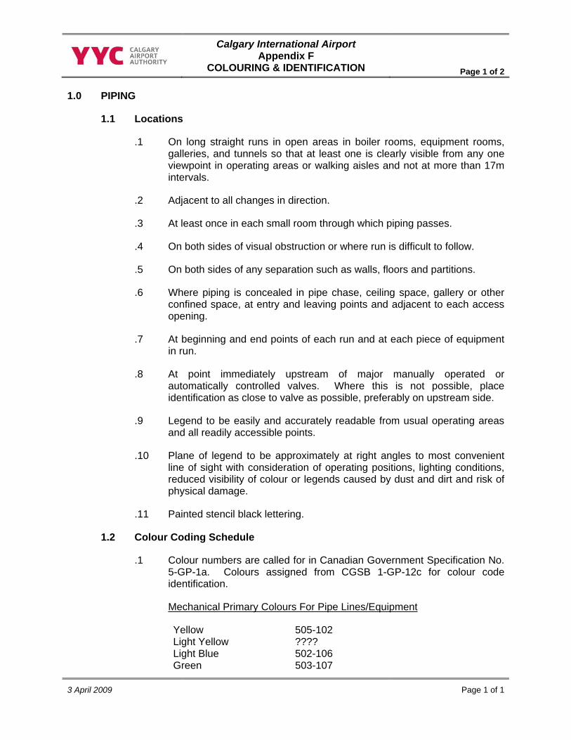
Calgary International Airport Appendix F
COLOURING & IDENTIFICATION Page 1 of 2
3 April 2009 Page 1 of 1
1.0 PIPING
1.1 Locations
.1 On long straight runs in open areas in boiler rooms, equipment rooms, galleries, and tunnels so that at least one is clearly visible from any one viewpoint in operating areas or walking aisles and not at more than 17m intervals.
.2 Adjacent to all changes in direction.
.3 At least once in each small room through which piping passes.
.4 On both sides of visual obstruction or where run is difficult to follow.
.5 On both sides of any separation such as walls, floors and partitions.
.6 Where piping is concealed in pipe chase, ceiling space, gallery or other confined space, at entry and leaving points and adjacent to each access opening.
.7 At beginning and end points of each run and at each piece of equipment in run.
.8 At point immediately upstream of major manually operated or automatically controlled valves. Where this is not possible, place identification as close to valve as possible, preferably on upstream side.
.9 Legend to be easily and accurately readable from usual operating areas and all readily accessible points.
.10 Plane of legend to be approximately at right angles to most convenient line of sight with consideration of operating positions, lighting conditions, reduced visibility of colour or legends caused by dust and dirt and risk of physical damage.
.11 Painted stencil black lettering.
1.2 Colour Coding Schedule
.1 Colour numbers are called for in Canadian Government Specification No. 5-GP-1a. Colours assigned from CGSB 1-GP-12c for colour code identification.
Mechanical Primary Colours For Pipe Lines/Equipment
Yellow 505-102 Light Yellow ???? Light Blue 502-106 Green 503-107
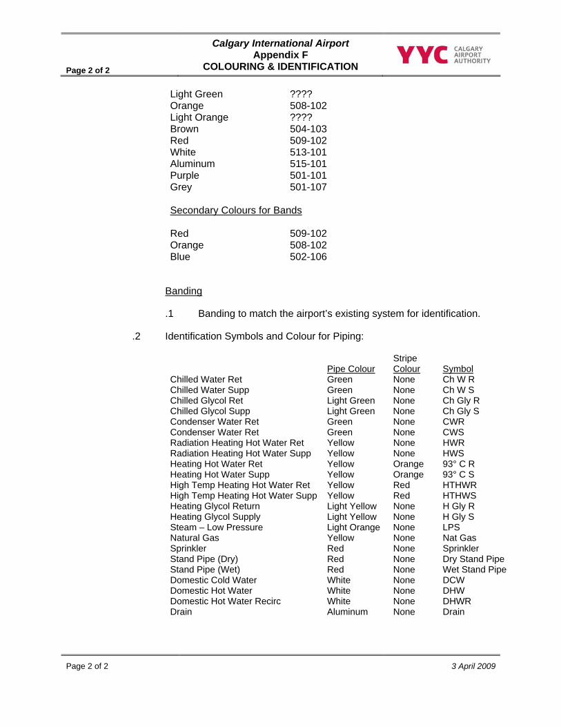
Page 2 of 2
Calgary International Airport Appendix F
COLOURING & IDENTIFICATION
Page 2 of 2 3 April 2009
Banding
.1 Banding to match the airport’s existing system for identification.
.2 Identification Symbols and Colour for Piping:
Light Green ???? Orange 508-102 Light Orange ???? Brown 504-103 Red 509-102 White 513-101 Aluminum 515-101 Purple 501-101 Grey 501-107 Secondary Colours for Bands Red 509-102 Orange 508-102 Blue 502-106
Pipe Colour Stripe Colour
Symbol
Chilled Water Ret Green None Ch W R Chilled Water Supp Green None Ch W S Chilled Glycol Ret Light Green None Ch Gly R Chilled Glycol Supp Light Green None Ch Gly S Condenser Water Ret Green None CWR Condenser Water Ret Green None CWS Radiation Heating Hot Water Ret Yellow None HWR Radiation Heating Hot Water Supp Yellow None HWS Heating Hot Water Ret Yellow Orange 93° C R Heating Hot Water Supp Yellow Orange 93° C S High Temp Heating Hot Water Ret Yellow Red HTHWR High Temp Heating Hot Water Supp Yellow Red HTHWS Heating Glycol Return Light Yellow None H Gly R Heating Glycol Supply Light Yellow None H Gly S Steam – Low Pressure Light Orange None LPS Natural Gas Yellow None Nat Gas Sprinkler Red None Sprinkler Stand Pipe (Dry) Red None Dry Stand Pipe Stand Pipe (Wet) Red None Wet Stand Pipe Domestic Cold Water White None DCW Domestic Hot Water White None DHW Domestic Hot Water Recirc White None DHWR Drain Aluminum None Drain
Appendix “G” Air Terminal Building Communication Systems
And Cabling Policy, Procedures & Standards
Page 1 of 27
Tenant Policies & Procedures June 2009
AIR TERMINAL BUILDING COMMUNICATION SYSTEMS AND CABLING POLICY, PROCEDURES & STANDARDS Date Issued: June 2005 Updated: June 2009 Airport Authority Contact: Paul Lawrence Director, Information Technology & Telecommunications
TABLE OF CONTENTS
1. DOCUMENT OVERVIEW ..................................................................................................................2 2. DEFINITIONS.....................................................................................................................................2 3. INFRASTRUCTURE OVERVIEW......................................................................................................2 4. COMMUNICATIONS INFRASTRUCTURE POLICIES & STRATEGIES .........................................3 5. GENERAL REQUIREMENTS (COMMON-USE AREA) ...................................................................4 6. REQUEST TO PERFORM WORK ....................................................................................................8 7. INSTALLATION REQUIREMENTS AND PRACTICES..................................................................10 8. MATERIALS USED .........................................................................................................................17 9. HORIZONTAL RUNS.......................................................................................................................20 10. LABELING.......................................................................................................................................20 11. TESTING..........................................................................................................................................25 12. DATA EQUIPMENT.........................................................................................................................26 13. RECORDS AND AS-BUILTS ..........................................................................................................27 14. CABLE MANAGEMENT INFORMATION REQUIREMENTS.........................................................27 15. ACCEPTANCE ................................................................................................................................27 16. SUBMISSION FOR EXCEPTION....................................................................................................27
Page 2 of 27
Tenant Policies & Procedures June 2009
1. Document Overview
This document is intended to provide infrastructure cabling guidelines for the implementation of communication systems at The Calgary International Airport. This document highlights the standards that tenants and their contractors must follow. This document contains policy, procedures, standards and installation practice guidelines. It shall be provided to contractors doing work on behalf of the tenants and the Calgary Airport Authority. The intent of this document is to assist tenants and their contractors to include the technical and infrastructure requirements in their planning and project development process. By incorporating these standards into the CIP submission, The Calgary Airport Authority will be able to process tenant requests quickly. As part of the Construction Installation Permit (CIP) process, all documentation must be submitted to the Development Coordinator - Airport Development - Planning for review and approval by The Calgary Airport Authority.
2. Definitions
• The Calgary Airport Authority – referred to as the Authority • Tenant – a person/company that has obtained a lease agreement from the
Authority in which to conduct business • Tenant Lease Area – area that the tenant has leased from the Authority • Tenant Contractor – The person/company that the Tenant has engaged to due
work within the tenant lease area. • Common Use area - all area outside of the tenant lease area that is not currently
under or available for a future lease agreement 3. Infrastructure Overview
The Authority has a Fibre Optic and Copper network throughout the terminal with the fibre network extending to various parts of the airfield. The fibre network will be used by the Authority and the tenants as required. The following documentation highlights the requirements for communication and cabling installation. The Calgary Airport Authority has implemented a NORDX/CDT Standard and requires tenants to take this into account when implementing systems within the airport. The NORDX/CDT Standard will be enforced for all fiber and horizontal runs that are implemented in the Authority’s common area. The only exception to this is the voice copper cable backbone structure discussed further in on this document. Any questions regarding this document or standards should be forwarded to the Development Coordinator – Airport Development - Planning and Manager, Telecommunications.
Page 3 of 27
Tenant Policies & Procedures June 2009
4. Communications Infrastructure Policies & Strategies
(a) Air Terminal Building Common-Use Area
(i) The Calgary Airport Authority will own, operate, and control all communications infrastructure within non-leased or common-use areas in the area defined as Air Terminal Building at the Calgary International Airport. The Authority shall ensure a reasonable and competitive pricing for the usage of such infrastructure for all users.
(ii) The Authority will provide this communications infrastructure from the Telecommunication Carrier’s main distribution rack or switch (located in the Authority’s Service Building) to each tenants lease line. This will consist of three (3) CAT 5 enhanced 4 pair cables, terminated on a Bix strip, and one (1) coaxial cable. Tenants will be required to provide their own termination equipment at lease line. All services will be provided within a reasonable timeframe.
(iii) The communications infrastructure shall be defined as: all fibre and copper cable, all conduit/raceways, termination equipment (non tenant), racking and enclosures (non tenant), active components and other telecommunications related facilities on Calgary Airport Authority property. This shared communications network (SCN) will be used as the backbone for voice, data, video, multimedia and special communications systems that are required for the ongoing operations and support of activities within the Air Terminal Building at the Calgary International Airport.
(b) Air Terminal Building Tenant Lease Area
(i) As the tenant is responsible for the infrastructure with-in their own lease space, it is recommended that the tenant takes due diligence in designs and that all designs should be reviewed by a BICSI RCDD or P. Eng. to ensure adherence to the applicable standards. The design must be provided to the Authority, listing the products used by part number and description. An explanation of the design must provide the location of the termination points, pathways, penetrations and capacities of the proposed cabling. The design shall conform to the standards of the NORDX/CDT IBDN Structured Cabling System guidelines or that of another manufacturer. All designs shall be submitted as per the CIP and TSR process.
(c) Strategic Alliance Telecommunications Infrastructure Projects
(i) The Authority and TELUS Communications Inc. (TELUS) have entered into a Strategic Alliance whereas TELUS is responsible for supporting the overall operation, maintenance and management of the telecommunications infrastructure and related services at the Calgary International Airport under the direction of the Airport Authority Information Technologies & Telecommunications department.
Page 4 of 27
Tenant Policies & Procedures June 2009
(ii) On behalf of the Authority and in recognition of this alliance, contractors are requested to solicit competitive quotations from TELUS for portions of work that have any relationship to telecommunications installation within the Authority’s tendering requirements.
5. General Requirements (Common-Use Area)
(a) Certification
(i) As the new Fiber backbone is a NORDX/CDT certified system, all work being performed in the common–use area must be done in a manner that will conform to this standard. All work is to be done by a NORDX/CDT Certified System Vendor and is to be done using NORDX/CDT certified technicians. All materials are to be NORDX/CDT or approved by NORDX/CDT to be a part of an IBDN Certified Structured Cabling System. All associated warranties as offered by NORDX/CDT will be applied to the work performed. All expansion to the fibre backbone will be performed by the Authority. Horizontal cabling certification will be the responsibility of the tenant.
(ii) Horizontal copper cabling within the ATB common-use area must be installed to NORDX/CDT IBDN Structural Cabling System guidelines. All cable must be at least CMR (FT4) rated to meet Building and CEC Code requirements. Cable specifications are included later in this document.
(b) Reference Materials
(i) Work performed must conform to the following standards including all addendums: (Where guidelines in two standards differ, the most stringent shall apply.)
(ii) Note the most recent issue of the standards listed below or the future published standards shall be used:
• ANSI/TIA/EIA 569 (CSA T530) - Commercial Building Standards for Telecommunications Pathways and Spaces
• ANSI/TIA/EIA 607 (CSA T527) - Grounding and Bonding Requirements for Telecommunications in Commercial Buildings
• ANSI/TIA/EIA 568B.1 (2000) - Commercial Building Telecommunication Cabling Standard
• 5.2.4 ANSI/TIA/EIA 568B.2 - Additional Transmission Performance Specifications for Enhanced Category 5 Cabling
• 5.2.5 ANSI/TIA/EIA 568B.3 – Optical Fibre Cabling Components Standard
• ANSI/TIA/EIA 606 (CSA T528) - Administration Standard for the Telecommunication Infrastructure of Commercial Buildings
Page 5 of 27
Tenant Policies & Procedures June 2009
(iii) The following materials shall be available for reference while performing work:
• BICSI TDM Manual
• BICSI Cabling Installation Manual
• NORDX/CDT Catalogue and Reference Guide
• NORDX/CDT IBDN Design and Engineering Manual
• NORDX/CDT IBDN Installation and Maintenance Manual
• The Calgary Airport Authority Planning and Engineering Air Terminal Building Technical Standards
(c) Credentials
(i) Contractors installing structured cabling in the common-use area shall be a NORDX/CDT CSV and utilize staff that has been trained by NORDX/CDT on the installation of the products used.
(ii) At least one member of the staff must be trained by NORDX/CDT on the IBDN Design and Engineering guidelines.
(iii) At least one member of the staff must be a certified BICSI RCDD.
(iv) A copy of NORDX/CDT certification certificate should be provided with your submission.
(v) All NORDX/CDT installers and designers shall have current NORDX/CDT manufacturer training.
• Manufacturer Training shall be current to within three years prior to project start date.
Note: Any requirement related to building modifications including coring, and sleeving must be reviewed and approved through the CIP process.
(d) Security
(i) Tenants and contractors must comply with all security orders, regulations and procedures, as established by the Authority.
(ii) Tenants and contractors must comply with all requirements of the Aerodrome Restricted Area Pass System and the CATSA Restricted Area Identification Card (RAIC) program. This policy has been enacted to provide positive identification of persons authorized to be in restricted areas on a “need and right to entry basis”. On establishing a need and right of entry to an airport-restricted area, a pass may be issued authorizing access to specific area within the airport. All access requirements shall be identified in the initial CIP submission prior to the start of the project.
Page 6 of 27
Tenant Policies & Procedures June 2009
(e) Hours of Work
(i) Hours of work are flexible but must be noted in the CIP. It is preferable that work involving large tools or equipment be done during less busy times in the late evenings. Airport Development must approve all work schedules.
(ii) Any impact on the existing Authority Cable Plant in terms of disruptions to general services must be reported to the Manager, Telecommunications.
(iii) Any anticipated noise or public safety issue must be reported to the Authority before the work is undertaken.
(f) Cleanup
(i) All debris from the work site must be cleaned daily.
(ii) Any tracking of mud, dust, debris, etc. through the Air Terminal Building that result from the construction must be immediately cleaned.
(iii) Proper barriers or dust collecting units must be used if the work will result in a proliferation of dust.
(iv) Replacement of ceiling tiles, insulation board, paralline ceiling, etc., must be immediately put back after completion of work, or in the interim if work is delayed or postponed for short periods of time. This includes the raceways along the outer perimeter bulkhead and north Terminal wall, both arrivals and departures levels.
(g) Safety
(i) All rules and guidelines as specified by the Alberta Occupational Health and Safety Act, the Canadian Code Part II and all regulations pursuant to these acts must be adhered to on Authority work sites.
(ii) Proper construction barricades shall be placed around the site when in public or high traffic areas.
• Airport Development must approve all barricades prior to commencing the project. Locations of the barricades must be determined with the Airport Development Department or the Airport Duty Manager.
(iii) Effective, Nov 4, 2004, the Canadian Air Transport Security Authority (CATSA) implemented a program for the random screening of non-passengers (NPS) at the Calgary International Airport.
• All personal that have access to restricted areas could be subject to screening.
Page 7 of 27
Tenant Policies & Procedures June 2009
(iv) You are not permitted to bring a prohibited item into a restricted area (except the necessary tools of the trade). If a prohibited item is intercepted, you may either surrender the item to a Screening Officer or leave the restricted area immediately. If you chose to leave the restricted area with the prohibited item, the Authority will be notified. See the NPS-CATSA documentation regarding further details, available at the Authority Pass Control Office.
(v) No tools shall be left unattended at any time. Tools left unattended within secure areas will be confiscated. Arrange for storage for tools and materials if working in a public area. Obtain approval before power actuated tools are used. Ensure that the operator of this type of equipment is certified to use it.
(vi) All materials delivered to the work site must be identified by size and weight, as there are restrictions in certain areas.
• NOTAMS (notice to airmen) are required for any work being done on airside areas.
• When coring concrete floors, X-ray is required for all holes, coring is to be done after hours, clean up must be done as work is ongoing, and the contractor will be responsible for damages to finished adjacent areas.
(vii) Any workers working on any area of more than 2.4 meters above the nearest permanent safe level must be utilizing personal fall protection gear, in compliance with Labour Canada and OH&S guidelines. We have cables and brackets installed in frequently used areas for this use.
(h) Conduit Provision
(i) The telecommunications infrastructure provided to each tenant’s lease line will consist of one empty 25mm conduit (1”) run from an Authority communications room or cable tray system to the tenant’s lease line closest to the communications room.
• This will contain three (3) CAT5 enhanced cables and one (1) coaxial cable.
• If applicable, the tenant will be responsible for extending this conduit and cable to his termination equipment location.
• Basic service requirements in excess of this conduit must be negotiated with the Authority leasing personnel.
• Conduits shall be run as per CED, Provincial, local jurisdictions and the Authority electrical standards.
• Provide a pull string in all empty conduits.
Page 8 of 27
Tenant Policies & Procedures June 2009
(i) Grounding
(i) All electronic equipment, racks, conduit and other equipment shall be grounded as per the applicable codes in use by the Authority. Approved Government and local codes shall take precedence over the requirements of this document.
(ii) All grounding requirements must be implemented to ensure personnel safety and equipment reliability. Industry-wide specifications, standards and applicable codes are required as a minimum and additional steps may be taken as required, based on system requirements and the site’s geographical area.
(iii) Abnormal and unusual conditions can sometimes require special effort to achieve an effectively bonded and grounded site.
6. Request to Perform Work
All contractors requested to perform work within the Calgary International Airport must have that work pre-approved by the Authority. All work must be performed within the guidelines of this document and the Air Terminal Building Technical Standards. Submissions for work are to be processed on a CIP (Construction Installation Permit) and a TSR (Telecommunications Service Request). (a) Designs
(i) Due diligence is required in designs; it is recommended that all designs shall be reviewed by BICSI RCDD or P. Eng. to ensure adherence to the applicable standards. The design must be provided to the Authority, listing the products used by part number and description.
(ii) An explanation of the design must provide the location of the termination points, pathways, penetrations and capacities of the proposed cabling. The design shall conform to the standards of the NORDX/CDT IBDN Structured Cabling System guidelines.
(iii) All designs shall be submitted as per the CIP and TSR processes.
(b) Drawing Submissions
(i) Drawing Submissions must include network schematics, equipment locations, and identify network protocols used. Submissions of drawings shall be in AutoCAD.
(c) Format of Submissions
(i) Drawings should be uniform in size; approximately 600mm X 900mm (24” X 36”) (A1) and should include the following information:
• Cable tray layout on cable tray line drawing, showing entire network system impacted by project
Page 9 of 27
Tenant Policies & Procedures June 2009
• Numbers and type of cable pairs used, and of those made available
• Room numbers of associated communications closets
• Network schematic showing equipment and location(s)
• Descriptions of equipment to be used at user’s end
• Telephone number or circuit number
• Name of the service provider (i.e. TELUS, Allstream, Shaw, etc.)
• Equipment specification sheets for equipment being installed in Authority closets
(ii) In addition to the above the drawings should indicate store location, configuration, name, and premises number on a key plan.
Note: These requirements are identified where the tenants system interfaces with the Airport Terminal Building backbone infrastructure.
(d) Closet Layout
(i) The contractor shall submit a drawing of existing and proposed terminations for any existing or proposed closets affected by the work. The placement and quantity of all new terminations shall be indicated on the drawing as well as the path of the cables within the room. Any equipment whether permanently or temporarily placed in the closet shall have its location indicated on the drawing.
(ii) Any active equipment must be noted and specification sheets provided showing physical dimensions, heat dissipation (BTU/hr), current draw (amps, phase, and volts), weight, and indicating any special environmental conditions which are required.
(e) Cable
(i) The contractor shall submit a drawing showing all cable paths from origination to termination. The drawing shall indicate any new or existing conduits used, trays used and penetrations made. Cable designations shall be indicated on the drawing.
(f) Scope of Work
(i) The tenant/contractor must submit a written explanation of the planned work.
• This must include the number, capacity and type of cable being installed or altered. It must provide a description of the areas that the work will be taking place and any access required to Authority areas or tenant space. Any equipment brought on site such as ladders, man lifts, and etc. that may pose a safety hazard must be listed.
Page 10 of 27
Tenant Policies & Procedures June 2009
(ii) The submitted scope of work must provide the number of technicians involved in the work with an indication of planned start and finish dates.
(iii) Approval for installation of RF devices above will still require Industry Canada Licensing. Licensing alone does not constitute approval for installation of RF equipment/systems at the Calgary International Airport.
7. Installation Requirements and Practices
(a) Installation Requirements
(i) All cable is to be run in conduit or communication trays.
• Minimum conduit size is 19mm. (3/4”).
(ii) All proposed new runs of conduit must be indicated on drawings and information regarding proposed routing must be provided for approval prior to issuance of a Construction Installation Permit (CIP).
(iii) Accurate and verified as-built drawings must be provided upon completion of all telecom/data installations. Drawings are to indicate number of pair run and CER.
(iv) All telephone outlet covers and pull boxes must be marked with the following information upon completion (following the Authority Communication Horizontal Cable Labeling Standards in Section 9).
• Type of usage (i.e. TEL or DATA)
• Destination point of cable (i.e. CER)
(v) Removal of all cables and associated connections is required when a system is no longer in use. Advise the Telecommunications Manager of cable pairs and block pairs now free as the result of this removal.
(vi) All cables must be C.S.A. approved, and be at a minimum CMR (FT4).
• The installation of PBX’s, key systems, CPE equipment, Central Office Equipment, Payphones, and other similar products is prohibited unless specially authorized in writing by the Telecommunications Manager via TSR/CIP.
(vii) All telephone lines, fax lines, etc. shall be serviced by an existing telephone switch located in the Services Building Room SB203.
(viii) All cable installed within the Air Terminal Complex common use areas is owned by the Authority. Tenants are responsible for cabling within their own areas. Any cable assigned to dedicated use by the tenants outside of their lease space must have an agreement with the Authority prior to installation.
• Use faceplates and jack(s) as per Authority standards.
Page 11 of 27
Tenant Policies & Procedures June 2009
(b) Communication Equipment Rooms (CERs)
(i) All work within CERs must be done as indicated on drawing submissions. Any cabling to BIX mounts is not to cross over jumper channels.
(ii) Any transition of cables from floor to ceiling or ceiling to floor is to take place as close as practical to corners or the edge of the backboard or through approved raceways.
(iii) If insufficient backboard space exists, the tenant is to provide additional space as required.
(iv) Any cables going to racks that are not adjacent to walls are to be carried via ladder cable tray.
(v) No cables are to run diagonally within a CER. All cables are to be fastened to walls in appropriate spacing to prevent sag or bulging of cables.
(vi) Fiber and Backbone copper cables will have minimal amount of service slack, i.e. no service loops are to be implemented, minimal slack to be left for proper termination and shall not exceed one meter in length. Horizontal copper cables will also have minimal amount of service slack, i.e. no service loops are to be implemented, minimal slack to be left for proper termination and shall not exceed one meter on length.
(vii) Cable ties are to be used with appropriate sized saddles; the cable must be dressed in with the bundle as opposed to tied on top of the bundle. Proper care must be taken to ensure cables are not squeezed or deformed. Additional cable support may require the installation of a cable trough system or alternate means to appropriately support the cable system.
(c) Connection to Backbone
(i) Under no circumstances is a tenant or a tenant’s contractor allowed to connect to the Authority backbone unless with written approval from the Authority. All connections to the backbone must be made by TELUS upon receiving approval from the Authority.
(d) Rack Layout
(i) Racks in CERs shall be laid out in the following fashion:
(ii) Power bars are to be mounted at bottom of rack (3U) and are reserved. Active components are to be placed at the bottom of the rack directly above power bar location.
(iii) Fibre panels are to be placed at the top of the rack followed by Category 5 enhanced patch panels.
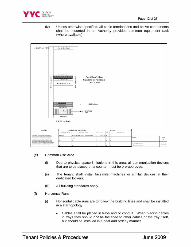
Page 12 of 27
Tenant Policies & Procedures June 2009
(iv) Unless otherwise specified, all cable terminations and active components shall be mounted in an Authority provided common equipment rack (where available).
(e) Common Use Area
(i) Due to physical space limitations in this area, all communication devices that are to be placed on a counter must be pre-approved.
(ii) The tenant shall install facsimile machines or similar devices in their dedicated lockers.
(iii) All building standards apply.
(f) Horizontal Runs
(i) Horizontal cable runs are to follow the building lines and shall be installed in a star topology.
• Cables shall be placed in trays and or conduit. When placing cables in trays they should not be fastened to other cables or the tray itself, but should be installed in a neat and orderly manner.
20/03/01
Page1 of 1
Typical CAA CommonEquipment Rack.vsd
LEGEND REFERENCE DRAWINGS REVISION
The recipient of this document agrees that the informationcontained herein is confidential and shall remain the sole andexclusive property of TELUS Advanced Communications.Disclosure of this information by TELUS AdvancedCommunications to the recipient shall not be construed as grantingor conferring, by license or otherwise, any rights in or to theconfidential information. The recipient of this document furtheragrees that the confidential information obtained by it from thisdocument shall be held in strict confidence, to be used exclusivelyfor the purpose intended by TELUS Advanced Communicationsand shall not be imparted by the recipient to others.
t804802
DRAWING NUMBER
>AB21934
>
>
>
>
DRAWING TITLE
>TYPICAL CAA Common Equipment Rack
Layout
>
>
>
>
Rev#
>
>
>
>
>
Date
00/12/14
>
>
>
>
BY
XYZ
>
>
>
>
DESCRIPTION
>
>
>
>
24/48 Str. Fib. Panel
15 inch Modem Shelf
Vertical W
ire Mngt.
Vertical W
ire Mngt.
Rack Base
1u power bar
19 20 21 22 23 2413 14 15 16 17 187 8 9 10 11 121 2 3 4 5 6
43 44 45 46 47 4837 38 39 40 41 4231 32 33 34 35 3625 26 27 28 29 30
1 2 3 4 5 6
7 8 91 01112
AB
12x
6x
8x
2x
9x
3x
10x
4x
11x
5x
7x
1x
Eth
erne
t
A
12x
6x
8x
2x
9x
3x
10x
4x
11x
5x
7x
1x
C
1 2 3 4 5 6
7 8 91 01112
AB
12x
6x
8x
2x
9x
3x
10x
4x
11x
5x
7x
1x
Eth
erne
t
A
12x
6x
8x
2x
9x
3x
10x
4x
11x
5x
7x
1x
C
1u hor. wire man.
R.F.Mote Rack
Load BatteryLineOn On
BatterySmartBoost
ReplaceBattery
Test
1u hor. wire man.
24 STR. MM FIBRE
CISCO Switches
APC 2200RMXLUPS
See CAA CablingStandard for Additional
Description
Page 13 of 27
Tenant Policies & Procedures June 2009
(ii) Care should be taken so as not to exceed fill limits (40%) when using conduit.
(iii) Care must be taken not to cause cable burn when pulling in cable.
(iv) Do not pull cables in conduits that have existing cables, any exceptions require prior approval from the Authority, maximum conduit fill in such instances shall not exceed maximum conduit fill as identified in ANSI TIA/EIA 569A standards.
(v) Do not exceed 90 meters on any horizontal cable.
(g) Backbone Runs
(i) Every ten meters there is to be a warning sticker placed lengthwise along the cable so that it can be clearly read. Bend radius and crush factors must be considered at all times. Fiber cable passing between floors is to do so within sleeves. Any penetration of walls is to be fire-stopped to Authority instructions.
(ii) Copper backbones are to be laid in trays in a neat and orderly manner or installed in conduit. Penetration between floors is to be in sleeves. Any penetrations through walls are to be fire-stopped.
(iii) All backbone fiber and cable that is run between communication closets and is designated as a redundant feed or feeds another communication closet as a redundant feed is to be installed in a manner that is physically separate from the main backbone run with minimal sharing of the same path.
(iv) All other installation standards listed in ANSI TIA/EIA 568B are to be followed.
(h) Antennae Installations
(i) The Authority, will request that any devices/ installed under this section have power emission and RF emission testing made once a year. The results are to be provided to the Telecommunications Manager
(ii) The Authority requires proof that the system to be installed will not cause RF interference with any Authority Operational and /or other system installed in the Calgary International Airport Property.
(iii) The Authority reserves the right to request the removal of any such device installed, if they feel that it may affect the operations of the Authority or the Calgary International Airport.
(iv) The Authority will require if requested proof that the RF emissions are safe and are within the Federal, Provincial and Municipal health and safety guideline.
Page 14 of 27
Tenant Policies & Procedures June 2009
(v) After the antenna location has been marked and approved, the installer shall remove the gravel ballast to the Fabrine membrane and install the base plate on the Fabrine membrane. The gravel ballast shall then be replaced up to the perimeter of the base plate pad.
(vi) If the base plate alone is not adequate to stabilize the antenna, concrete blocks or a heavier base plate shall be used. The use of sandbags for stabilization is not acceptable.
(vii) Base plates shall be steel plate, approximately 760mm X 760mm X 6.3mm in size. The steel plate shall be painted to protect from rusting.
(viii) Antennas must be mounted to a freestanding base plate. Attachment to the building or building components is not permitted.
(ix) Under no circumstances should the PVC membrane be cut or punctured. A qualified Sarnafil repair technician shall be brought in for any installations, which require penetrations of the PVC membrane.
(x) Entrance to roof areas is allowed only under the supervision of an Authority employee. To arrange access, contact the Structural Facilities Manager – 735-1334.
(xi) All communication cables within the building shall follow existing cable trays and ducts. Where no cable trays or ducts exist, cables must be run in conduit (E.M.T. minimum 19mm). All conduits are to be terminated within 400mm of the tray or duct.
(xii) All access to roof level must be through an approved weather head fitting. Conduits shall be sealed for weatherproofing. Locations for new entries are to have the prior approval of the Telecommunications Manager.
(xiii) No conduit runs shall be allowed on the roof without prior written approval of the Authority.
(xiv) All antennae must be metal and tagged with in the following manner:
Company Name: Air Canada Contact Phone: (403) xxx-xxxx Frequency/Type of Service: UHF Radio – Fr800.94-2 Connects to Com Room: M8065
The contact should be for the area responsible for maintaining and supporting the antenna.
Antenna tags may be obtained from:
Roblyn Engraving Ltd. 1927 Highfield Crescent, S.E. Calgary Alberta T2G 5M1 (403)251-5656
Page 15 of 27
Tenant Policies & Procedures June 2009
Request them to use the Calgary Airport Authority antenna tag standard.
(xv) All satellite dishes are to be tethered via braded metal cable to their base.
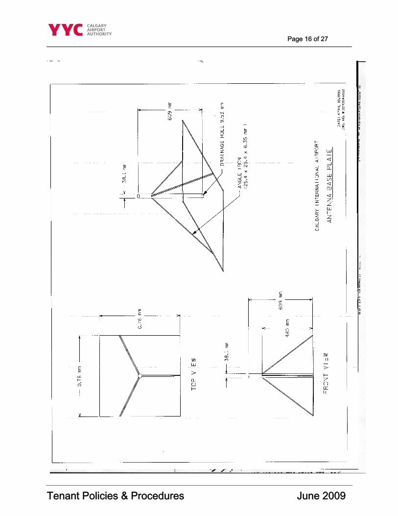
Page 16 of 27
Tenant Policies & Procedures June 2009
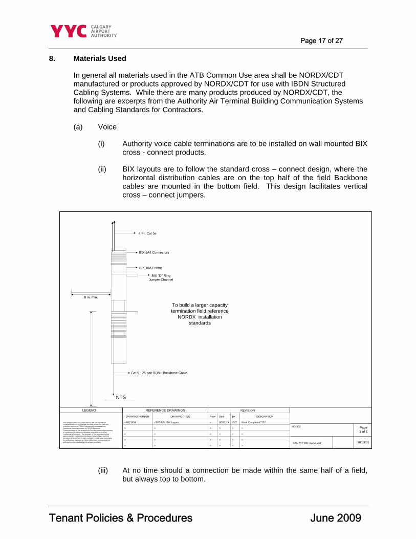
Page 17 of 27
Tenant Policies & Procedures June 2009
8. Materials Used
In general all materials used in the ATB Common Use area shall be NORDX/CDT manufactured or products approved by NORDX/CDT for use with IBDN Structured Cabling Systems. While there are many products produced by NORDX/CDT, the following are excerpts from the Authority Air Terminal Building Communication Systems and Cabling Standards for Contractors. (a) Voice
(i) Authority voice cable terminations are to be installed on wall mounted BIX cross - connect products.
(ii) BIX layouts are to follow the standard cross – connect design, where the horizontal distribution cables are on the top half of the field Backbone cables are mounted in the bottom field. This design facilitates vertical cross – connect jumpers.
(iii) At no time should a connection be made within the same half of a field, but always top to bottom.
20/03/01
Page1 of 1
CAA-TYP BIX Layout.vsd
LEGEND REFERENCE DRAWINGS REVISION
The recipient of this document agrees that the informationcontained herein is confidential and shall remain the sole andexclusive property of TELUS Advanced Communications.Disclosure of this information by TELUS AdvancedCommunications to the recipient shall not be construed as grantingor conferring, by license or otherwise, any rights in or to theconfidential information. The recipient of this document furtheragrees that the confidential information obtained by it from thisdocument shall be held in strict confidence, to be used exclusivelyfor the purpose intended by TELUS Advanced Communicationsand shall not be imparted by the recipient to others.
t804802
DRAWING NUMBER
>AB21934
>
>
>
>
DRAWING TITLE
>TYPICAL BIX Layout
>
>
>
>
Rev#
>
>
>
>
>
Date
00/12/14
>
>
>
>
BY
XYZ
>
>
>
>
DESCRIPTION
Work Completed????
>
>
>
>
NTS
BIX 10A Frame
BIX "D" RingJumper Channel
BIX 1A4 Connectors
Cat 5 - 25 pair BDN+ Backbone Cable
4 Pr. Cat 5e
8 in. min.
To build a larger capacitytermination field reference
NORDX installationstandards
Page 18 of 27
Tenant Policies & Procedures June 2009
(b) Data
(i) Authority fibre backbone is terminated in three different manners. It terminates in either a Fibre Manager (type 1), a free standing RF Mote 19” x 77” rack or a wall mount Hubbell 19” x 48” swing rack (type 2 and 3).
(ii) The fibre backbone interconnecting rooms U69D06, U59D01, SB203, M58G01, and U42D01 terminates on a NORDX/CDT Fibre Manager.
• The right side of the Fibre Manager is for single-mode terminations. The fibre is fusion spliced to 1-meter single-mode ST pigtails mounted in a 6 port termination module.
• The left side is for multimode fibre and is fusion spliced to 1-meter multimode ST pigtails mounted in a 6 port termination module.
(iii) Other closets housing fibre backbone are on either wall mount swing gate racks or free standing racks.
• The fibre is fusion spliced to ST pigtails, either single-mode or multi-mode and is mounted in Fibre Express panels.
• The left side is for multimode and the right side is for single-mode.
• The Fibre Express panels will hold up to 24 or 48 strands of fibre.
(iv) The Authority data horizontal copper cabling terminates on the same racks as the fibre, with the exception of the rooms with Fibre Managers.
• The copper cables terminate on NORDX/CDT PS5 series of patch panels. There is a requirement for a 1U horizontal cable management panel for every 24 ports provided.
(v) The Calgary Airport Authority horizontal distribution fibre or copper terminates on the same type of equipment and may use the same racks, although the termination housing (patch panel or fibre express) is separate. Horizontal cables must always terminate on a separate panel and be mounted on the lowest available space on the rack.
(c) Tenant Cables
(i) All tenant cables, whether fibre or copper, shall be terminated on the same type of equipment as Authority cables.
(ii) There needs to be a clear differentiation between Authority cables and the tenant cables, thus the tenant cables must not terminate on the Authority rack unless the cables are being provided by the Authority as a point of demarcation.
(iii) BIX fields will follow the standard design, but separate mounts will need to be provided by the tenant.
Page 19 of 27
Tenant Policies & Procedures June 2009
• All locations for BIX mounting assemblies must be pre-approved by the Calgary Airport Authority.
• For data cables, patch panels are required.
• Tenants may terminate voice cables on patch panels as well but it must be noted that connections to the Authority voice backbone need to be converted to BIX. These panels are to be mounted on the Authority provided common equipment racks.
(iv) Tenant racks may only to be provided with special permission from the Authority.
• Under no circumstances will a tenant, or a tenants contractor, connect to the Authority backbone unless under the direction of the Authority.
• All connections to the Authority backbone and equipment must be made by TELUS under full disclosure to and with the approval of the Authority.
• No connections will be made to any equipment or patch panels unless they are installed by the tenant.
(d) Rack Layout
(i) Racks in telephone CERs shall be laid out in the following fashion:
(ii) Two power bars are to be mounted at bottom of rack with space below for an optional or future UPS.
(iii) Active components are to be placed at the bottom of the rack directly above power bar location.
(iv) Fibre managers are to be placed at the top of the rack followed by category 5 enhanced patch panels.
(v) Unless otherwise specified, all cable terminations and active components shall be mounted in an Authority provided common equipment rack (where available).
(vi) All racks are to be bolted to the floor per manufacturer’s specifications.
(e) Shallow CERs
(i) There are some CERs in use which do not have sufficient depth to handle the type of terminations previously listed. The Authority fibre cables terminate in a NORDX/CDT wall mounted Fibre Express Panel. These are fusion spliced to factory made pigtails. The top half of the box is for multimode and the bottom for single mode.
Page 20 of 27
Tenant Policies & Procedures June 2009
(ii) Tenant fibres must terminate in the same manner although variances in connector types are permitted. All copper cables must terminate on equipment as described in the voice and data section.
9. Horizontal Runs
(a) Direct
(i) Direct runs of 4 pair cable from telecomm CERs to common-use outlets are to be minimum NORDX/CDT Category 5 Enhanced cables, CMR rated (minimum FT4). One separate cable is required per RJ45 jack.
(ii) Terminations are to be on NORDX/CDT EZ – MDVO Modules and mounted in NORDX/CDT MDVO faceplates, adapters or boxes. Modules are to be PS5 – 8 pin, 568A coded, with gray modules for data and white modules for telephone. Faceplates shall be white nylon with filler plates required.
(b) Backbone Runs
(i) Fibre backbone runs are to be NORDX/CDT indoor/outdoor armored fibre for both multimode and single mode.
(ii) Single mode is to have a yellow jacket and multimode is to be orange. These fibre cables are a special order through NORDX/CDT.
(iii) Voice backbones are to be IBDN Plus 25 pair cable or IBDN D-Inside (non-plenum).
• IBDN Plus 25 pair cable is to be used for small pair counts and runs under 90 meters.
• IBDN D-Inside (non-plenum) is to be used for runs of pair counts larger than 25 pair and runs over 100 meters, a single cable consisting of multiples of 25 may be used.
• Cables run through duct banks must be suitable for that application.
10. Labeling
All labeling is to conform to ANSI TIA/EIA-606 standards and the consulting engineer with regard to color. Numbering and location of labeling is to conform to the Authority Communication Horizontal Cable Labeling Standards set forth in Section 7.
(i) Labels on copper cables are to be Panduit self-laminating adhesive wire markers produced with a laser printer.
(ii) Labels on fibre cables are to be Panduit Fibre Optic Cable Marker Rigid (non-adhesive) Tags.
Page 21 of 27
Tenant Policies & Procedures June 2009
(iii) Labels on outlet faceplates may be either Panduit computer printable labels or labels produced with a Brother P Touch Label Maker or equivalent product.
(b) Communication Horizontal Cable Labeling Standards
(i) The Authority has set the following labeling standards.
(ii) This document is divided into four sections.
• Section 1: where a horizontal cable/fiber is terminated in an end user’s location from a riser room
• Section 2: where a cable/fiber is not terminated in a riser room but is terminated into a public area, common use area or tenant within the ATB
• Section 3: to be used for all active components located in a riser room
• Section 4: to be used for circuit designators that all cables, fibers, and leased line must have in order to be entered into FACTS database. The circuit designators do not have to be labeled on the cable but should be identified somewhere at the end user’s location i.e. - outlet, jack, patch panel.
(iii) Once the label has been established, TELUS or the Authority is to be notified of the label to ensure it is entered into the cable management database (FACTS).
(c) SECTION 1 Horizontal Cable
(i) Three types of end horizontal cables have been determined, minimum CAT5E, Fiber, and a leased line.
(ii) The following definitions apply to each of the cable types.
• Any cable been installed to an end user will have the following labels attached to both ends of the cable (riser room terminator considered a label) and if applicable on the faceplate of the terminated end.
• Horizontal cable – any horizontal cable utilizing a Category5E cable, or greater, which will be used for a single circuit application. When a horizontal cable is terminated within a riser room, it is to be given a sequential number based upon how many horizontal cables are presently terminated.
• Fiber – consists of any fiber cable being installed from a riser room to an end user.
• Leased Line – any cable being installed in which each pair is to be utilized for a different circuit application. (Authority standard is 3 CAT5E 4 pair).
Page 22 of 27
Tenant Policies & Procedures June 2009
(iii) With regards to each type of horizontal cable, the following labeling practices must be followed to ensure cable identification and cable tracking. Once the label has been established, TELUS or the Authority is to be notified of the label to ensure it is entered into the cable management database (FACTS).
(A) CAT5E/Fiber labeling: Category 5E cable & fiber is to be labeled with the following standard whose definitions can be found from the criteria below and with reference to the CAD drawings of the ATB.
1) XXXXXX-YZZZ
a) With “XXXXXX” being the Tenant/final destination of the horizontal cable with reference to either the room number or Grid designation.
b) With “Y” being derived from the following table.
c) With “ZZZ” being the terminated number of that horizontal cable. Horizontal cables when terminated within a riser room will be labeled sequentially.
(B) An example of the labeling is listed below.
1) M58V02-D002
a) M58V02 is the quadrant grid number of the room (this can also be the room number where the horizontal cable is terminated)
b) D is the service type (data)
c) 002 mean that it is the second horizontal cable that has been terminated in the riser room.
d) The labeling of the cable should be done both in the Riser room and in the termination room (on the cable itself) and finally on the faceplate of the outlet jack.
TYPE OF SERVICE “Y” Designator Voice V Data D Video/Security S Alarms A HVAC H Fiber F
Page 23 of 27
Tenant Policies & Procedures June 2009
(iv) Leased line labeling:
(A) Leased line cable is to be labeled with the following standard whose definitions can be found from the criteria below and with reference to the CAD drawings of the ATB.
1) WWWWWW-XXXXXX-ZZ
a) With “WWWWWW” being the final Riser Room from which the Leased line has been terminated.
b) With “XXXXXX” being the room number to where the lease line has it’s end termination.
c) With “ZZ” being the sequential numbering of the individual cable pairs.
d) An example of the labeling is listed below.
RCC-001-01 RCC-001-02 RCC-001-03
RCC is the riser room RCC (rental car center); this could also be the room number of the riser room
001 is the room number to which the leased line is terminated.
01, 02, 03 are the sequential numbering of the leased line pairs.
(d) SECTION 2 Backbone Cable
(i) For a room to room circuit that utilizes either cable or fiber and does not terminate in a riser room, it is to have the following label on either end of the cable and where applicable on the faceplate of the terminated end.
(A) WWWWWW-XXXXXX-YY-ZZ
1) With “WWWWWW-XXXXXX” as being the room numbers with the first designator as being the lowest room number. Labeling of both ends of the cable should be the same; room numbers are not to be transposed.
2) With “YY” as being the derived from the following table.
TYPE OF SERVICE “YY” Designator Single Mode fiber SM Multimode Fiber MM CAT5E C5
Page 24 of 27
Tenant Policies & Procedures June 2009
3) With “ZZ” as being the sequential numbering of the numbering of the circuits in that room.
4) An example of the labeling is listed below.
U42D01-U69D06-MM-01 U42D01 as being the first room number, in this case a riser room (note 1) U69D06 as being the second room number (note 1) MM as being a multi mode fiber 01 as being the number of the fiber runs. Note 1: U42D01 room is lower than U69D06; it is to be placed first on the label. This is inclusive of the alphanumeric structure.
(e) SECTION 3 Active Equipment
(i) For any Riser room that has active components in it, whether floor, wall or rack mounted the following labeling standards are to be used to identify the equipment.
(A) XXXXXX-YYYY-ZZZZZZ
1) With “XXXXXX” as being the riser room “room number”
2) With “YYYY” being derived from the following table.
3) With “ZZZZZZ” as being a six-alpha/numeric description of the equipment being labeled.
4) An example of the labeling is listed below
U69D06 -0002-HUB002 U69D06 is the riser room number. R02 is the rack number in the riser room. (Cabinets generally labeled CA?) HUB002 is the second hub on that rack.
TYPE OF SERVICE “YYYY” Designator
Rack/Cabinet Number XXXX Wall mounted WALL Floor mounted FLR
Page 25 of 27
Tenant Policies & Procedures June 2009
(f) SECTION 4 Tenant Cable
(i) This section of labeling is to be used for data entry into the FACTS cable management database. All circuit labeling is to be done per TELUS’s circuit designators except where an
(ii) In-house circuit exists and is not in the TELUS database. In this case, the following practice will be adopted.
(A) XXXX-Y-ZZZZ
1) With “XXXX” is an alpha/numeric description of the tenant/company for which the circuit has been installed.
(This section yet to be defined for all tenants).
2) With “Y” is derived from the following table.
3) With “ZZZZ” being the sequential number of the circuit.
4) An example of the labeling is listed below.
ACA-F-0001 ACA is an alpha/numeric for Air Canada Airlines F means that it is a dark fiber used 0001 is the number of the fiber used
11. Testing
(a) Fiber
(i) All fiber installed at the Airport shall be tested using a power meter and light source.
(ii) Test results will be required to verify meeting or exceeding the manufacturer specifications for the fiber cable and mated connectors. A hard copy of the power meter results shall be provided to the Authority upon completion.
TYPE OF SERVICE “Y” Designator Dark Fiber F Voice V Alarm circuit A Data D Power/Video/Security S
Page 26 of 27
Tenant Policies & Procedures June 2009
(iii) An OTDR must be available to trouble shoot any anomalies in the test results or conduct testing at the discretion of the Authority or the consulting engineer.
(iv) Power meter and light source testing shall be performed at standard wavelength (850nm) in BOTH directions.
(b) Copper
(i) All 4 pair copper rated Category 5 or higher performing channels shall be tested in accordance with TSB 67.
(ii) The testing shall be done as a channel test, which includes patch cords at each end of the cable.
(iii) Testing shall be to 350 MHz. Category 5 multi pair cables shall be done as a link test. Copper test results shall be provided to the Authority in both hard copy and current electronic media. Preferred tester is Fluke DSP2000 or DSP4000. A written request for tester substitution must be submitted to the Telecommunications Manager for approval prior to testing.
(iv) All backbone cable rated Category 3 shall be tested for continuity, polarity and resistance utilizing a standard digital millimeter.
12. DATA Equipment
The Authority has implemented a updated data network consisting of NORTEL switches with a few Cisco switched located on the outside edge of the network. (a) Installation of Tenant Data Equipment
(i) Before the installation of any data equipment in an Authority CER, approval must be obtained from the Authority Telecommunication Manager. A Telecommunications Service Request (TSR) must be submitted complete with a drawing showing the rack layout and location. The TSR and all pertinent information is to be e-mailed to the Manager, Telecommunications for approval at the following e-mail address [email protected]
(b) Assignment of new Ports on switches
(i) Prior to any new port being activated on the network devices, information regarding the settings of the port is to be obtained, i.e. 10Mbs/100Mbs half/full duplex and that information is to be used to hard code the port settings.
(ii) Port settings will not to be set for auto sensing unless either information is not available or the device being put on the LAN requires that auto sensing is set.
Page 27 of 27
Tenant Policies & Procedures June 2009
13. Records and As-Builts
Cable records must include cable numbers, cross–connections and test results.
(i) Cable numbers shall be placed at the outlet location on as built drawings.
(ii) As built drawings of the cables and termination closet shall be provided, both hard copy and CD-ROM or other electronic format (if in electronic format, must be in AutoCAD format).
(iii) A block diagram of networks and their associated hardware shall be provided.
14. Cable Management Information Requirements
All cabling information is to be captured and provided to the Authority as per the “Cable Management Information Requirements (Contractor Data Collection Process)” document.
15. Acceptance
Authority acceptance of the work performed will be based on the completeness of cable records and drawings as well as test results, neatness and compliance to standards. Any work not deemed to meet these criteria needs must be rectified immediately. A copy of the application for certification must be submitted to the Authority upon completion.
16. Submission for Exception
Any requests for exceptions will need to be highlighted as exceptions in the submitted scope of work. Exceptions will be considered only if they do not jeopardize the NORDX/CDT Certification.
End of document
Appendix “H” Cable Management Information Requirements
Page 1 of 6 Cable Management Information Requirements (Contractor Data Collection Process) Date Issued: June 2008 Effective Date: June 2009 Prepared By: Director, Information Technologies & Telecommunications 1. Background:
The Calgary Airport Authority has both a copper and fiber optic cable infrastructure. There are approximately 95 communication rooms in the Airport Terminal Building (ATB), about 12,000 cable pairs, and miles of tie trunk cable. The fiber optic backbone consists of both single mode and multi mode colour coded cable.
The Terminal Building was constructed in approximately 1976. From 1991 to present, the building standard for copper cable has been IBDN 4pr level 5, 24 AWG. In 1998 a fiber optics-cabling infrastructure was introduce. The cable plant also extends the Airport Terminal Building to cargo row and the Airside Maintenance Complex. Currently the Authority is using Cat 5E cable for trunks and horizontal wiring.
TELUS, on behalf of the Authority, maintains the telecommunications cable records for the Calgary Airport Authority using a database and application known as the Fibre and Cable Tracking System (FACTS).
2. Purpose:
The purpose of this document is to provide instructions for companies who perform telecommunications cable installations for the Calgary Airport Authority and our constituents with instructions on what information is required to be collected and turned over to the Calgary Airport Authority for input of the cable records by TELUS into FACTS.
The requirement for the collection of cabling records into FACTS is part of the Telecommunications Services Request (TSR) process, and must be completed for all Construction Installation Permits (CIPS) and all Capital Projects with a Telecom component.
3. Cable Management:
Cables are used as a transmission media for telephone calls, fax machines, and data. A copper cable consists of a number of “cable pairs”. As a rule each cable pair can be connected to one device (i.e. telephone, fax machine, etc.) Thus a tie cable with 100 cable pairs can handle about 100 devices. Fiber Optic cable uses light to transmit information down the silicon fiber. Through multiplexing many devices can be served by a single strand of fiber.
Page 2 of 6
At the Calgary International Airport, telecommunications cabling provides service to airlines, tenants, and the Authority. In order to provide the desired communication service to the end user in a timely manner, capacity must be available on either fiber optics or copper cables, thus the need to treat this capacity as an inventory asset.
In order to manage inventory a computer program was installed that allows us to track cable usage and location. Tracking cable usage allows for the following benefits:
(a) Faster trouble shooting of cable failures
(b) Preplanning for cable capacity upgrades
(c) Improved quality control of installations
(d) Aids in preplanning for CIPs and Capital projects
4. Capture of new cable information for input into FACTS:
When a cable installation is being performed by a contractor the following information MUST be recorded into the attached data collection sheet called “Calgary Airport Authority Cable Record Changes”
The contractor must provide the following information:
(a) Customer: Who the circuit is for and the carrier, example Westjet/TELUS
(b) Circuit: This will be either voice circuit or data circuit.
(c) Line Equipment: This is the central office equipment location, or PBX.
(d) Entrance cable: Shall be the cable pairs on the MDF.
(e) XCONN1…4: The installer shall record each cable pair that they have cross connected in each communications room, use as many rows on the sheet as required to capture all of the cross-connects. Include the communications room number beside the cable pair. Cable connections will be recorded down to the device outlet. Refer to the Calgary Airport Authority Communications Systems & Cabling Standards for more detail on labeling standards.
(f) Termination Comm. Room/Jack/Eqpt: List of the end device and room of the termination end of the circuit, example telephone room M61D01.
Notes: Information that maybe required for trouble shooting or pertinent information.
If a cable run is from comm. room to comm. room, then it is to be entered into the data sheet above (fields that do not apply are to be marked N/A).
5. Fiber Installations

Page 3 of 6
When a tenant has requested either dark fiber or a V-LAN type connection the following must be submitted:
(a) Fiber Optics cable information must be provided on the attached cable
information collection form.
(b) The contractor must detail all connections for the fiber or data from originating end to terminating end. This will include the following:
(c) Fiber manager ports,
(d) Cross-connects,
(e) Connections to active components,
(f) Patch panels,
(g) End devices.
6. New Telecommunications Systems:
When a new communications system (CCTV, security, cable TV, parking, telephony or other systems) is added to or expanded upon at the Calgary International Airport and the RFP requests cabling information to be entered into the CMS cable system the contractor shall: The contractor shall prepare all information to have all cables, and their terminations entered into the Calgary Airport Authority’s FACTS cable management system. This will include:
(a) If a terminal block or strip is being used that has not previously been entered into
CMS. The contractor shall provide the information for TELUS to build the templates and graphical representation for the terminal block or strip.
(b) Enter all terminations of cables including terminal strips, or blocks into the CMS cable data capture sheets.
(c) Prior to entry of the cable information into CMS the contractor shall submit a sample cable entry template to the Calgary Airport Authority for approval.
Submittal:
(i) The Contractor shall submit the cable record collection data to the Calgary Airport Authority Project Manager for review and acceptance.
(ii) The project manager will provide the cable collection data to the Calgary Airport Authority’s Telecommunications Manager and TELUS, who will evaluate the completeness of the information provided and its acceptability for entry into the CMS. If the cable record information provided to the Calgary Airport Authority is deemed to be unacceptable then the following may occur:
Page 4 of 6
(iii) The contractor maybe asked to verify and resubmit the cable records.
(iv) The Calgary Airport Authority may ask TELUS to go and recapture the cable record information and these costs will be billed back to the contractor.
(v) Cable record information must be provided to the Calgary Airport Authority as part of the required documents package that is submitted to the Calgary Airport Authority prior to acceptance of a project. The date for submittal of cable records shall be built into the project delivery schedule, and be accepted by the Calgary Airport Authority Project Manager.
Note: TELUS must have completed the input of the cable records into the CMS prior to acceptance of the final project.
7. Audit Process:
The cable records information provided by the contractor shall be subject to an audit by TELUS, on behalf of the Authority, to confirm the completeness and accuracy of the data provided.
This audit will include a visual and physical inspection of 10% of the cables installed to confirm both accuracy of the cabling information provided to the Calgary Airport Authority. If there is a discrepancy found then the following may occur:
(a) The contractor maybe asked to verify and resubmit the cable records.
(b) The CAA may ask TELUS to go and recapture the cable record information and these costs will be billed back to the contractor.
8. Technical Support and Assistance:
The Contractor is responsible for the capture of and submittal of cable records to the Calgary Airport Authority. It is the responsibility of the contractor to ensure that all information gathered is in a format acceptable to TELUS for data input into FACTS. If the contractor has questions they may contact:
TELUS On-site Supervisor: 403-503-3775 Calgary Airport Authority Manager, Telecommunications 403-735-1338
9. Costs:
The costs for the capture of cable records shall be the responsibility of the contractor.

Page 5 of 6
The costs for TELUS to input cable records into FACTS are to be the responsibility of the contractor and they are required to make the necessary arrangements with TELUS to have input completed.
The costs for TELUS Technical support are the responsibility of the contractor.
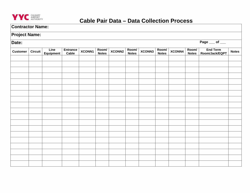
Cable Pair Data – Data Collection Process
Contractor Name:
Project Name:
Date: Page ___ of ___
Customer Circuit Line Equipment
Entrance Cable XCONN1 Room/
Notes XCONN2 Room/Notes XCONN3 Room/
Notes XCONN4 Room/ Notes
End Term Room/Jack/EQPT Notes
Appendix “I” Parkade Rental Kiosks & Lot Identification Details
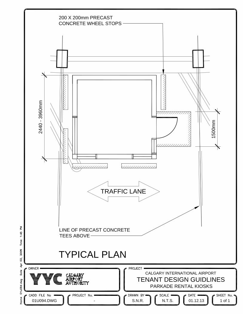
TRAFFIC LANE
TYPICAL PLAN
200 X 200mm PRECASTCONCRETE WHEEL STOPS
LINE OF PRECAST CONCRETETEES ABOVE
1500
mm
2440
- 39
60m
m
CALGARY INTERNATIONAL AIRPORT
TENANT DESIGN GUIDLINESPARKADE RENTAL KIOSKS
01U094.DWG - S.N.R. N.T.S. 01.12.13 1 of 1
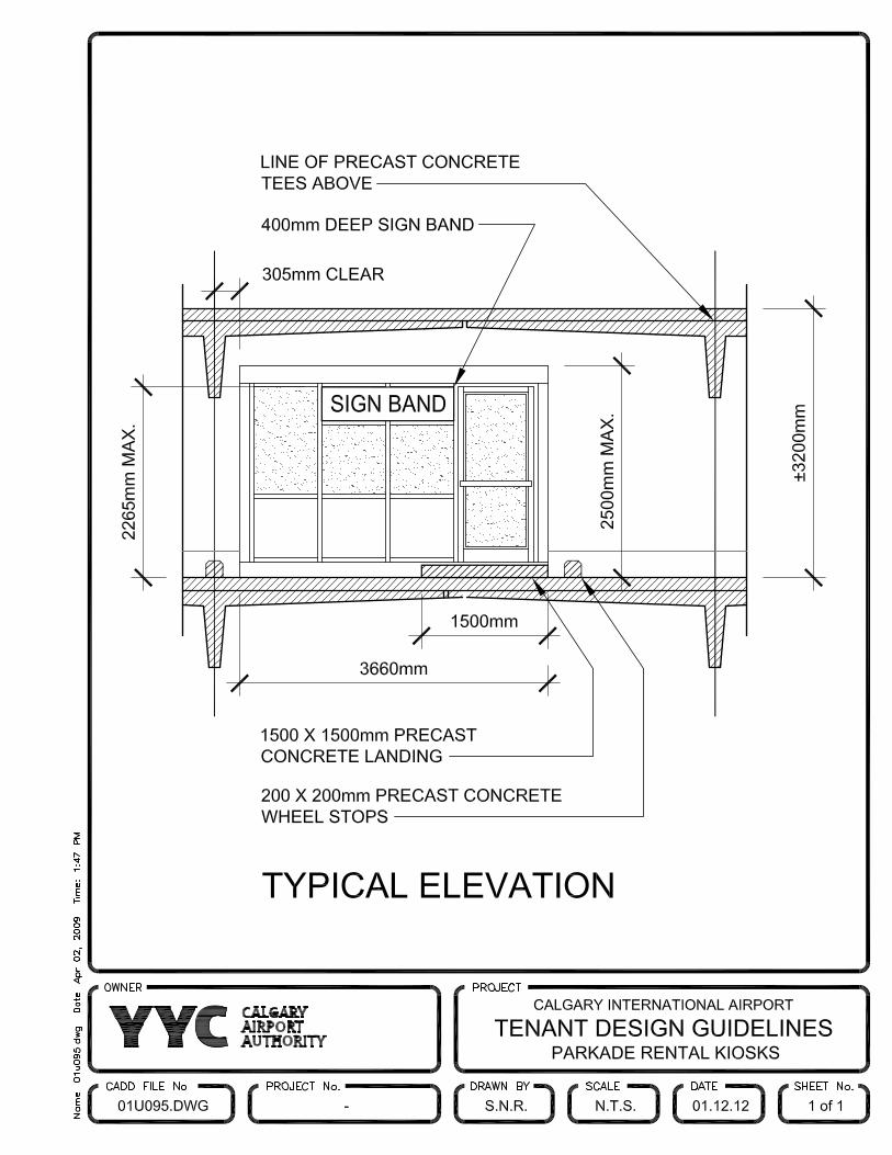
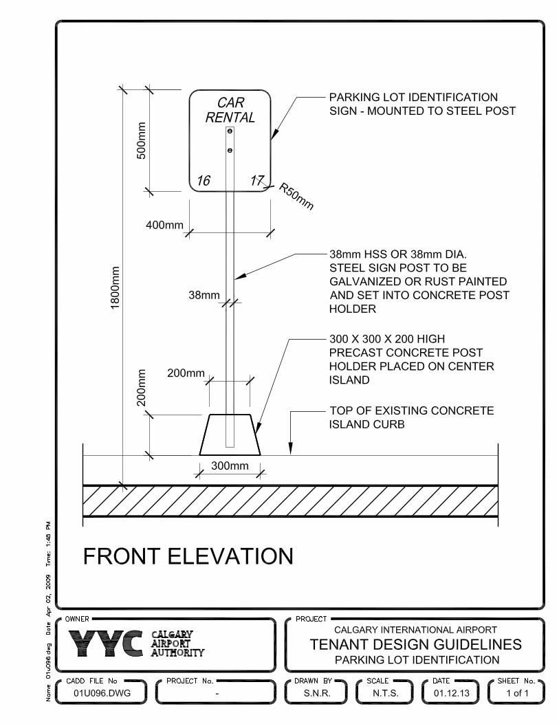
Appendix “J” Air Terminal Building Design Themes
Calgary International Airport Tenant Design Standards & Guidelines
Terminal Building Design Themes
January 2009 Page 1 of 3
1.0 TERMINAL BUILDING DESIGN THEMES
The architectural design for the public areas of Calgary International Airport takes its inspiration from the natural and man-made features that are unique to southern Alberta. A palette of earth toned floor tile and custom designed carpet, natural stone, wood and glass is used throughout the public spaces of the Terminal Building.
To further enhance a sense of place, the Calgary Airport Authority has established an overall design theme for the Terminal Building that can be interpreted as “Rhythms of the Landscape”. Specific design elements such as commissioned art work, graphics, colours, forms and materials have been developed for the public concourses, processing and waiting areas, embarking/disembarking points and designated meeting areas. The finishes and colours of the theme works are reflective of the established Terminal Building colour and material palette.
Tenants and their designers should be conscious of the Terminal Building design themes described below and storefronts and store interiors should reflect the spirit of the specific theming of the area where they are located.
1.1 Concourse A and Concourse A Hammerhead
The design theme for Concourse A is Western Heritage: The Stampede, the round-up, chuck wagon races, all of the action and pageantry of the West. Commissioned artwork located throughout “A” Pier will focus on “Horse and Man”, the interplay of forms and colours, when man and beast perform as one. Floor mounted sculptures of “true stories” will be featured throughout the concourse, embracing the community aspects of life in Calgary and Alberta.
1.2 Ticketing Hall
The design theme for the Departures Level Ticketing Hall is “People at Play”. Elements within this space are designed to celebrate the opportunities for playful recreation offered in Alberta, skiing, cycling, rafting, etc. Sculpted figures in action, some precarious, others stable, but all showing a moment of adventure high above the visitor’s heads The result is the creation of three dimensional compositions colourful when viewed as a whole and fascinating in detail when viewed individually. Artwork and installations are “light” and entertaining, taking the opportunities presented by the architectural features of large glazed walls and high spaces.
1.3 Concourse “B”
To be developed
1.4 Concourse “C”
To be developed
Calgary International Airport Tenant Design Standards & Guidelines
Terminal Building Design Themes
January 2009 Page 2 of 3
1.5 “D” Domestic Arrivals Hall
The design theme for the “D” Domestic Arrivals Hall is “First Impressions”. Flanked by the Canadian Shield to the east and the Rockies to the west, the deep layers of horizontal rocks under the Plains hold a rich cache of previous life forms.
1.6 International Arrivals Hall
The main design feature of the International Arrivals Hall is a rock wall that changes in colour and texture as the traveler exits from the restricted area and enters the Arrivals Hall. Water cascading over the rock surface is designed to produce a “white” water effect while also creating sound. Within the geological formations, drawings derived from early First Nations cultural and spiritual images are revealed to the viewer by a series of controlled light sources. Stones representing the tipi ring or meeting place, inset into the floor, are located between the rock wall/water feature and a sculpted figure, a symbol of ceremonial dance and welcome.
1.7 North Processor Retail Hall
Located within a glazed and high ceiling space, the Retail Hall provides views to the Western landscape across the Airport lands. The area provides extensive seating for the traveler prior to proceeding to their departure gate. It is assumed that more time is spent here than most other areas of the Airport. The design theme for the Retail Hall is “The Big Sky” as this space enjoys full views of the ever-changing Alberta skies over the distant landscape, with natural light filling the space for most of the day. Pure sunlight is white, composed of seven colours of the rainbow (a spectrum). As it passes through our atmosphere, it is split into its rich variety of colours. Clear skies are blue, sunsets are fiery red; when sunlight strikes ice and water particles spectacular rainbows are created.
1.8 North Processor Lantern Hall
The design theme for the North Processor Lantern Hall is “Transformations”. The lantern is a vaulted rectilinear space. Located between the “D” Widening lounge and the “D” Pier Food Court, the area is subject to high traffic volumes. Using sculptural skeletal forms, commissioned artwork describes the transition from the “flying reptiles” in Alberta’s prehistoric past to birds of feather.
1.9 Concourse D Food Court
The design theme for Concourse D Food Court is “Aviation”. From wing shaped suspended canopies above the tenant counters to whimsical suspended fabric “clouds” above the seating area, design elements in the Food Court evoke the magic and fantasy of commercial aviation from the days of Alberta’s flying pioneers to a vision of the world to come.

Calgary International Airport Tenant Design Standards & Guidelines
Terminal Building Design Themes
January 2009 Page 3 of 3
1.10 Concourse D Hammerhead
The design theme for Concourse D Hammerhead is “Up, up and Away”. Characterized by a high vaulted ceiling, elements in this space are designed around those daring feats of the flying machine. Sometimes foolish, but always fearless, the pioneering spirits who broke the barriers of air travel in Western Canada. The bush pilots, explorers and entrepreneurs, who by taking advantage of every advance in aircraft technology, contributed to the economic and social development of Alberta.
Appendix “K” Office Signage Detail and Placement