caledonian railway cables
DESCRIPTION
Caledonian Railway Cables Railway Signalling Cables Railway Communication Cables Railway Power & Control Cables, The cables are used as cabling wires for the relays and electronic equipments in the Traffi c Control Center and Trackside Equipment Shelter. The CV cables are suitable for use Optical Control Panel (OCP) wiring, indoor interconnection of railway network equipments. The cables are halogen free fire resistant, inductive protected and armoured. BS 6853 -1a, DIN 5510-1 1-4, UNE 21123, NFF 16-101 F0 Standard and etc.Website: www. caledonian-cables.co.uk www.caledonian-cables.deContact : NikiEmail: [email protected]TRANSCRIPT

Caledonian Railway CablesRailway Signalling CablesRailway Communication CablesRailway Power & Control Cables
www.caledonian-cables.co.ukwww.addison-cables.com


1
Caledonian Railway Cableswww.caledonian-cables.co.uk
TABLE OF CONTENTS
1www.caledonian-cables.co.uk
Caledonian Railway Cableswww.caledonian-cables.co.uk
European Signalling System for Rail Industry 001
Electrification System for Rail Industry 004
Basic Design for Railway Cables 004
Cables for Railway Application 017
RAILSIG Railway Signalling & Control Cables 020
Equipment Cables for Control Centre
France RATP Railway StandardCV /CVZ Indoor Equipment Cables ………………………………………………………………… 021ZUG/ ZUT/ SUG Indoor Equipment Cables ………………………………………………………… 023SCG Local Control Cables …………………………………………………………………………… 025
Multicore Signalling & Control Main Cables for Trackside
German DB Railway StandardAJ-2Y2YDB2Y S(H115)/S(H145)/S(H95) …………………………………………………………… 026A-2Y2YB2Y S(H115)/S(H145)/S(H95) ……………………………………………………………… 030A-2Y2Yv S(H115)/S(H145)/S(H95) ………………………………………………………………… 033
UK NETWORK RAIL StandardTYPE A1, A2 & A3 Railway Signalling Cable ……………………………………………………… 036TYPE B1 & B2 Railway Signalling Cable …………………………………………………………… 038TYPE C1 & C2 Railway Signalling Cable …………………………………………………………… 040TYPE C3 Railway Signalling Cable …………………………………………………………………… 041TYPE D1 & D2 Railway Signalling Cable …………………………………………………………… 042TYPE E1 & E2 Railway Signalling Cable …………………………………………………………… 044TYPE E3 Railway Signalling Cable …………………………………………………………………… 046
Spain RENFE Railway StandardEAPSP n×1×1.4 ………………………………………………………………………………………… 048CCPSSP-FR0.3 n×1×1.4 ……………………………………………………………………………… 050CCTSST-FR0.3 n×1×1.4 ……………………………………………………………………………… 052
Multipair/Multiquad Signalling & Control Cables for Trackside
German DB Railway StandardAJ-2Y(L)2YDB2Y S(H45) …………………………………………………………………………… 054A-2Y(L)2YB2Y S(H45) ………………………………………………………………………………… 057
TABLE OF CONTENTS

2 www.addison-cables.com
A-2Y(L)2Yv S(H45) …………………………………………………………………………………… 059France RATP Railway Standard Intercity Main Lines
ZPAU & ZPAU-SH Main Signalling Cables (AC Electrifi ed Lines) ………………………………… 061ZPFU & ZPFU-SH Main & Local Signalling Cables (DC Electrifi ed Lines) ……………………………… 063ZPGU Local Signalling Cables (DC Electrifi ed Lines) ………………………………………………… 065ZCO3 & ZCO3-SH Main Signalling Cables (AC Electrifi ed High Speed Lines) ………………… 067
France RATP Railway Standard Urban SubwayK23 LSZH Subway Signalling Cables for Metro/Local Trains/Tramlines ………………………… 069K24 LSZH Subway Signalling Cables ……………………………………………………………… 071K13 PVC Subway Signalling Cables for Metro/Local Trains/Tramlines ………………………… 073Digicode 30KHz Indoor Signalling Cables ………………………………………………………… 075Inductive Loop Cable …………………………………………………………………………………… 077
Spain RENFE Railway StandardEAPSP n×4×0.9/1.3/1.4 ……………………………………………………………………………… 078CCPSSP-FR0.3 n×2×0.9/1.4 ………………………………………………………………………… 081CCPSSP-FR0.1 n×4×0.9/1.4 ………………………………………………………………………… 083CCPSSP-R-FR0.1 ……………………………………………………………………………………… 085CCTSST-FR0.1 n×4×0.9/1.4 ………………………………………………………………………… 087CCTSST-FR0.3 n×4×1.4 ……………………………………………………………………………… 089
Belgium SNCB Railway StandardSXCAV & SXCAG Signalling Cables ………………………………………………………………… 091
Swiss SBB Railway StandardSW-CLT Switching Centre Cables …………………………………………………………………… 093
UK NETWORK RAIL StandardTwin Datalink Cable …………………………………………………………………………………… 095
Axle Counter Cables
UK NETWORK RAIL StandardRT/F3 D & S & B type Axle Counter Cable ………………………………………………………… 096RT/F3 E1/E2/E3 Type Axle Counter Cable ………………………………………………………… 099
Balise Cables
French KVB SystemSPFB Speed Control System Cables ………………………………………………………………… 101
European ERTMS SystemEUROBALISE SIF ……………………………………………………………………………………… 102EUROBALISE BGA …………………………………………………………………………………… 103
Fire lntegrity Cables
France RATP Railway StandardK27 Fire Resisting Control Cables (CR1-C1 Class) ………………………………………………… 105MD4 Fire Resisting Telecom Cables (CR1-C1 Class) ……………………………………………… 107
RAILSIG/RAILOPTICS/RAILDATA/RAILCOX Railway Telecom Cables 109

3
Caledonian Railway Cableswww.caledonian-cables.co.uk
Telecommunication Cables for Outdoor Plant
UK NETWORK RAIL StandardRT/ZHLS, A-2Y(L)2Y External Telephone Cables to NR/PS/TEL/00015 ………………………… 110Scada/Pilot Cables NR/PS/ELP/27220 ……………………………………………………………… 113Outdoor Single Mode Trackside Fiber Cables NR/PS/TEL/00014 ………………………………… 115
UK LU London Underground StandardG7621 Trackside Communications Cables ………………………………………………………… 117G7622 Trackside Communications Cables ………………………………………………………… 119G7623 Trackside Communications Cables ………………………………………………………… 122
France RATP Railway StandardMD4 Medium Distance Trackside Telecom Cables ………………………………………………… 124ST2513/CT2243 Outdoor Single Mode Unarmoured Trackside Optical Fiber Cables ………… 126CT2242 Outdoor Single Mode Armoured Trackside Optical Fiber Cables ……………………… 128
Telecommunication Cables for Indoor Plant
France RATP Railway StandardK20 & L120 LSZH Armoured F/FTP Cat6 Cables ………………………………………………… 130K209B LSZH Armoured Optical Fiber Cables ……………………………………………………… 132K26 LSZH 50/75Ω Coaxial Cables …………………………………………………………………… 134
RAILFEEDER Railway Power & Control Cables 137France RATP Railway Standard
K25 Track Feeder Cables to NF F 55-625 …………………………………………………………… 138UK NETWORK RAIL Standard
450/750V Track Feeder Cables to RT/E/S/21101 …………………………………………………… 140450/750V LSZH Track Feeder Cables to EME-SP-14-025/SE908 ……………………………… 142450/750V LSZH Single Core Conduit Wires to EME-SP-14-026 ………………………………… 1430.6/1KV Limited Fire Hazard/Fire Survival Multicore Armoured Cables to EME-SP-14-027 …… 145LU Section 12 Fire Integrity Cables ………………………………………………………………… 148500/750V Fire Survival Mineral Insulated Multicore LSZH Cables to EME-SP-14-028 ………… 150Pigtail Rail Connection Cables to SE260L …………………………………………………………… 153450/750V Limited Fire Hazard Earthing Cables to SE774 ………………………………………… 154300/500V Limited Fire Hazard Track Circuit Feeder Cables to SE895 …………………………… 1550.6/1KV Limited Fire Hazard Rail Connection Cables to SE902 ………………………………… 156Concentric Signalling Cables Type 1 to SE1047 …………………………………………………… 157Trackside Signalling Aluminium Power Cables to BR880 ………………………………………… 159Point Heating Cables to NR/SP/ELP/40045 ………………………………………………………… 161FTN Screening Conductor Cables …………………………………………………………………… 163NSGAFOU Cables …………………………………………………………………………………… 16433KV Power Cables to BS 7835 NR/PS/ELP/00008 ……………………………………………… 16611KV LSZH Power Cables to BS 7835 ……………………………………………………………… 16712/20(24)KV Power Cables to CENELEC HD620 & C 33-226 …………………………………… 16933KV LSZH Power Cables to BS 6622/BS 7835 …………………………………………………… 172
TABLE OF CONTENTS
www.caledonian-cables.co.uk

4 www.addison-cables.com
1800V DC Positive Traction Cables ………………………………………………………………… 174300V DC Negative Traction Cables ………………………………………………………………… 176
FIRERAIL Traction Cables For Railway Applications 1780.45/0.75KV Single Core Standard Wall Traction Cables ………………………………………… 1790.45/0.75KV Multicore Standard Wall Traction Cables …………………………………………… 1800.45/0.75KV Single Core Thin Wall Traction Cables ……………………………………………… 1820.45/0.75KV Multicore Thin Wall Traction Cables …………………………………………………… 1840.6/1KV Single Core Medium Wall Traction Cables ………………………………………………… 1860.6/1KV Multicore Medium Wall Traction Cables …………………………………………………… 1880.6/1KV Single Core Thin Wall Traction Cables …………………………………………………… 1910.6/1KV Multicore Thin Wall Traction Cables ……………………………………………………… 1930.6/1KV Single Core Dual Wall Traction Cables …………………………………………………… 1960.6/1KV Multicore Dual Wall Traction Cables ……………………………………………………… 1981.8/3KV Single Core Standard Wall Traction Cables ……………………………………………… 2021.8/3KV Single Core Medium Wall Traction Cables ………………………………………………… 2041.8/3KV Single Core Dual Wall Traction Cables …………………………………………………… 2063.6/6KV Single Core Standard Wall Traction Cables ……………………………………………… 2083.6/6KV Single Core Medium Wall Traction Cables ………………………………………………… 2103.6/6KV Single Core Dual Wall Traction Cables …………………………………………………… 212300/500V Single Core Thin Wall Fire Resistant Traction Cables ………………………………… 214300/500V Multicore Thin Wall Fire Resistant Traction Cables …………………………………… 2150.6/1KV Single Core Medium Wall Fire Resistant Traction Cables ……………………………… 2171.8/3KV Single Core Medium Wall Fire Resistant Traction Cables ……………………………… 219
RAILDATA Databus Cables For Railway Applications 221WTB (Wired Train Bus) Cables ……………………………………………………………………… 222MVB (Multifunction Vehicle Bus) Cables …………………………………………………………… 224MVB (Multifunction Vehicle Bus) Cables (Redundant Version) …………………………………… 226WTB (Wired Train Bus)/MVB (Multifunction Vehicle Bus) Cables ………………………………… 227Integrated 9/11/18/20 Cores 0.75mm² UIC Databus Cables ……………………………………… 229Category 5E Data Cables ……………………………………………………………………………… 231
Ordering Information 233

001
Caledonian Railway Cableswww.caledonian-cables.co.uk
European Signalling System for Rail Industry
Interoperability has become a keyword in the European Rail
sector. It is easy to see there is an urgent need for a harmonized,
interoperable train control system. At least seven proprietary ATP
systems (Bombardier, Alstom, Invensys, Alcatel, Ansaldo/CSEE,
Siemens /ZUB) were installed in European railway, creating a
considerable barrier to Interoperability. A deep change in the
communication and signalling system is taking place with the new
ERTMS projects (European Rail Traffic Management System). Its
purpose is to set up a common ATP/ATC System through Europe,
allowing trains to cross borders easily and therefore increase the
competitiveness of railways on international corridors for freight and
passengers. The vision is to operate all high-speed lines and most
other conventional lines through ERTMS/ETCS in Europe.
In the early days of ETCS development, Siemens and other signalling suppliers worked together within the
EUROSIG group, which defi ned and specifi ed the ETCS components to ensure compatibility and interoperability of the
various sub-components and sub-systems. Siemens was the fi rst to offer the S21 Eurobalise for commercial projects.
German Rail (DB) has chosen the Berlin--Halle/Leipzig line as one of the European pilot lines for commercial operation
at ETCS Level 2. The objectives of the pilot project are to demonstrate the interoperability of the system, employing
components developed by various manufacturers. The line is equipped with conventional axle counters and lineside
signals. For ETCS Level 2 operation, the line will have three radio block centres, each connected via LAN to the relevant
electronic interlocking, and approximately 1000 S21 Eurobalises. Installation of GSM-R (Global System for Mobile
Communications--Railways) has been successfully completed, covering the basic functionality of ETCS Level 2, such as
movement authorisation.
The Signum system (Automatic Train Warning System –ATW) was the fi rst in the Swiss Rail network to provide help
or supervision to drivers. It signifi cantly increased the safety with acoustic signals in cabins coupled with distance signals.
However, this ATW system had no impact on network capacity. The French equivalent ATW system was the “crocodile”
based on another technical concept, which of course was a problem to interoperability. When Swiss Federal Railways
(SBB) introduced new signals in the 1990s, the ZUB system (Automatic Train Protection – ATP, with balises on the
tracks) was introduced in order to launch emergency barking in case of exceeding specifi c needs. Such a system was
mainly implemented in German speaking countries, whereas in France for example it was the KVB. At least 10 different
ATW/ATP systems were then developed in Europe, creating a considerable barrier to Interoperability.
What is ERTMS The European Rail Traffi c Management System has been defi ned in 3 levels
ERTMS Level 1:
EUROPEAN SIGNALLING SYSTEM FOR RAIL INDUSTRY
www.caledonian-cables.co.uk

002 www.addison-cables.com
A. Eurobalises - Overlay to Existing Signalling System.
- Movement Authorities through Eurobalise.
- Train Integrity & Position by Track Circuit.
B. Eurobalises with infill (Euroloop or radio or extra balises)- Overlay to Existing Signalling System.
- Movement Authorities through Eurobalise.
- Train Integrity & Position by Track Circuit.
ERTMS Level 1 is a Train Control System based on track-to-train communication by an intermittent system. The
system includes Lineside Encoder Units (LEU) which is designed to acquire traffic information and convert this into
conditioning messages to be sent to the balise for subsequent processing by the On Board equipment. Each LEU can
command up to 4 balises. Each Encoder cabinet can house up to 8 LEUs. The maximum distance between balises is
5 km. Connection to Computer Based Interlocking is either through a safety protocol stack based on “Profi bus”, or
HDLC proprietary serial link. Purpose of the Eurobalise is to transmit a message to the On-Board equipment in order to
advise the driver and the On-Board ATP processing unit about the train positioning and the conditions of the track and
traffi c ahead, and hence take the appropriate actions for train speed and for the protection of the train itself, passengers
and infrastructure alike. LEUs and Eurobalises are linked through a suitable connection cable. The On Board equipment
serves to calculate the dynamic speed profi le, select the most restrictive speed value, compare the train's actual speed
with the permitted speed and, if necessary, perform brake application. Radio In-fi ll is a functionality that can be optionally
added to the ERTMS Level 1 in order to increase the performance of the line. Purpose of the Radio Infill Unit is to
transmit the message corresponding to the Eurobalise in advance with respect to the Eurobalise placed at the signal. In
this way, a train approaching a signal at stop can revoke braking as soon as the signal clears without waiting to get to the
signal itself. The In-fi ll message is transmitted via radio using GSM-R and Euroradio safety protocols, as in ERTMS Level
2. The use of radio allows a continuous infi ll coverage at unlimited distance from the signal.
The train will stop and wait and will not pass the balises until the signal turns
from red to green
On Board Trainborne Equipment
Track Circuit
Eurobalises
Lineside EncoderUnits
With the Infill loop functionality, the train will receive a message in advance to pass this signal before reaching the
balises. Therefore, the train can accelerate immediatelywhen the signal goes from red to green
On Board Trainborne Equipment
Track Circuit
Eurobalises
Lineside EncoderUnits
Infill Loop

003
Caledonian Railway Cableswww.caledonian-cables.co.uk
ERTMS Level 2: Eurobalises + Euroradio (GSM-R) + Radio Block Centre (RBC)
- No more Trackside Signals Required.
- Movement Authorities through GSM-R.
- Train Position via Eurobalise.
ERTMS Level 2 is a Train Control System based on data communications between the Centralized Block Centre
and the trains, via a radio system. ETCS Level 2 brings the introduction of radio transmission for railway signalling i.e.
GSM-R (Global Standard of Mobile Communication-Rail) in the frequency range of 900 MHz. In this case, the Eurobalise
acts as intermittent transmission device, mainly for location reference. The Radio Block Centre (RBC) is wayside
redundant management system designed to provide information continuously to each train and knows from trains their
positions; it receives track circuits and route status information from the Automatic Block System and from Interlockings.
ETCS Level 2 combines many advantages as follows:
- Long term compatibility with other European railways by use of Eurobalise beacons;
- On-board signalling by use of radio transmission with the GSM-R protocol;
- Minimum amount of devices in the track, what reduce time and costs for track maintenance.
ERTMS Level 3: Eurobalises + Euroradio (GSM-R) + Radio Block Centre (RBC)
- Movement Authorities through GSM-R.
- Train Position via Eurobalise.
- Train Integrity Onboard. Moving Block.
There are only a few players providing the very fi rst High Speed Line in commercial service running solely on an
ERTMS Level 2 system. Beside Europe, countries like China and India also embracing this advanced signalling system.
Thousands of kms of ERTMS Level 1 lines are in operation or under construction also.
Movement authority and track position are transmittedover the radio between the Radio Block Center and the train,acquiring up-to-date information without any lineside signals.q g p y g
On Board Trainborne Equipment
Track Circuit
Eurobalises
Radio Block Center
Interlockingo
Train integrity checking is done on boardand therefore track circuits are not required.
The train can run on moving block.
On Board Trainborne Equipment
Eurobalises
Interlocking & Radio Block Center
Track Positionand Integrity
EUROPEAN SIGNALLING SYSTEM FOR RAIL INDUSTRY
www.caledonian-cables.co.uk

004 www.addison-cables.com
Electrifi cation System for Rail Industry
The electric railway needs a power supply that the trains can
access at all times. Transmission of power is always along the track
by means of an overhead wire (catenary) or at ground level, using an
extra, third rail laid close to the running rails. AC systems always use
overhead wires, DC systems can use either an overhead wire or a
third rail, both are common.
The railway electrification system supplies electrical energy to
the trains at different voltages which include 600V DC, 750V DC,
1500V DC, 3000V DC, 15KV AC 16⅔Hz & 25KV AC 50Hz. The lower
voltages are often used with third or fourth rail systems and voltages
above 1000V are normally limited to overhead wiring for safety reasons. 750 volt DC third rail supply has been used
extensively in UK for trains running up to 145 km/h, which is about its limit for speed.
25KV AC is the preferred system for high-speed and long distance railways, commonly adopted in Europe, India and
United States. DC system is the preferred option for shorter lines, urban systems and tramways. 1500V DC is commonly
used in Netherlands, Japan, India, France, New Zealand and United States, 3000V DC is commonly used in Belgium,
Italy, Spain, Poland and South Africa.
While use of a third rail does not require the use of DC, in practice all third-rail systems use DC because it can carry
41% more power than an AC system operating at the same peak voltage. Third rail is more compact than overhead
wires and can be used in smaller-diameter tunnels, an important factor for subway systems. DC systems are limited to
relatively low voltages, and this can limit the size and speed of trains and the amount of air-conditioning the trains can
provide. This may be a factor favoring overhead wires and high voltage AC, even for urban usage. In practice the top
speed of trains on third-rail systems is limited to 100mph (160km/h) because above that speed reliable contact between
the shoe and the rail cannot be maintained. Besides the third rail, fourth rail system may be adopted, as found in the
London Underground. The additional rail carries the electrical return that on third rail and overhead networks is provided
by the running rails. On the London Underground, a top contact third rail is beside the track, energized at +420V DC and
a top contact fourth rail is located centrally between the running rails at -210V DC, which combine to provide a traction
voltage of 630V DC.
Basic Design for Railway Cables
As a global supplier, Caledonian offers extensive range of copper and fi ber cables in three key economic sectors:
infrastructure, industry and building. Our cables are used in rolling stock, railway infrastructure, energy and telecom
networks, automobiles, shipboard, oil, mining & petrochemical, windmill applications, etc. Caledonian has always been
at the forefront of meeting the requirement of the most advanced railway standards within the ERTMS. The ERTMS
requires high levels of EMC performance. Caledonian signalling and control cables are designed and built to comply with
such EMC requirements, with the use of special insulation and sheath materials with different screening designs.

005
Caledonian Railway Cableswww.caledonian-cables.co.uk
Caledonian designs a wide range of signalling and control (branded as RAILSIG), power (branded as
RAILFEEDER), coaxial (branded as RAILCOX), fi ber optic (branded as RAILOPTICS) and databus cables (branded as
RAILDATA) specially adapted to rail environments, providing enhanced fi re performance, oil resistance and fl exibility.
In rail sections including the station, trackside and tunnel, virtually all the cables have to be halogen free, as well as fi re
retardant, and assure low toxicity and minimal smoke to enhance survival, fi re fi ghting and emergency operations.
Caledonian covers wide area network for main line, metropolitan area network for subway, light rail and intercity
arrival/departures, and station range cable for effi cient rail management. Caledonian can provides optic fi ber for both
analogue and digital railway applications such as (ESTMS/ETCS). Caledonian can also offer reliable cables to power the
trackside equipments and provide low frequency communications.
Copper multicore, multipair and multiquad are used for signalling and control cables. Caledonian signalling and
control cables guarantee electromagnetic immunity critical for communications from catenaries and current rail. They
are designed to survive along the track, resistant to high temperatures, humidity, oil and ultra violet light. They have
high dielectric strength, and come in low smoke halogen free and fi re retardant versions suitable for tunnels, stations
and platforms. The cables can be customized to provide different reduction factor, special fi re performance sheathing
and specifi c color coding. Caledonian signalling and control cables exhibits exceptional performance because of special
manufacturing process, choice of suitable insulation and sheathing materials for the rail environments.
Caledonian railway cables offer Rail authorities and operators, contractors a wide range of cable solutions, which may be
one of the world's most comprehensive and technologically advanced answers to rail industry.
Caledonian has developed railway cables that meet the challenges posed by railway industry for low smoke and
toxicity, even in a system that has the stringent requirement in the world. London Underground, a thriving railway system
that carries a billion passengers in a year, also lay claim to be the oldest train system in the world. The fi rst underground
railway to operate electric train, it is usually referred to as a tube, thanks to the shape of the tunnel far below the street
level. Built in late 1800s, the long tunnels were not designed for optimum fi re safety. In fact, the long sections are designed
without exits. As a result, if a fi re began inside the tunnels, smoke and fumes will overwhelm the passengers, who would have
no ready means of escape. Therefore, extreme precautions are taken to prevent the occurrences of fi re smoke, fume and toxic
vapor, which is one reason the system standard for smoke and toxicity is the most stringent of any rail systems in the world.
Low smoke and fume, low toxic and oil resistant
The railway industry has the exact requirements for cables that are used in both infrastructure (the tunnels)
and rolling stock (trains). These requirements cover underground train, tunnels, railways, subway, tram, trackside
and mass rapid transit propulsion equipments. Safety is the critical issues. In fact, smoke and fume levels deemed
safe are specified in different standard including BS 6853(UK), NFF 16101(France), DIN 5510 (Germany) and TS
45545-2(Europe).
Caledonian become aware of the market demand for a low smoke and fume, halogen free railway cables that would
meet London Underground BS 6853 for low smoke and low toxicity, while also providing excellent resistance to mineral
oil, withstanding IRM 903 for 7 days at 100℃ .
Flame retardant, UV resistant and temperature resistant
In addition to low smoke and toxicity in the event of fi re, the cables are featured by
-Highly fl ame retardant
-No acid gas emission during fi re
-Mineral oil resistence at high temperature (IRM 903 7 days at 100℃ )
-Wide operating temperature from -40℃ to 120℃
BASIC DESIGN FOR RAILWAY CABLES
www.caledonian-cables.co.uk

006 www.addison-cables.com
-Weathering testing indicates 20-years UV resistance.
-Can be crosslinked via dry silane or e-beam technology to achieve high temperature resistance.
Caledonian railway cables can be designed to offer an extremely wide operating temperature range of +125℃ down to -60℃ ,
a very low smoke density and are always classifi ed as short circuit cable and earth fault-proof cables
Anti Induction for Railway Signalling & Control Cables
The magnetic fi eld resulting from the power supply voltage of the catenaries (25KV A.C.) induces an electromotive
force (e.m.f) in all conductors subjected to this fi eld. If a conductor is protected by a conductive e metallic sheath, the e.m.f
decreases from V1 to V2. The ratio rk = V2/V1 is called the screening or reduction factor. This screening or reduction factor is
measured according to CCITT standard, requiring the cable sample of 2m length should achieve the required values for this rk
factor as given in the table here below.
ZPAU- Multipair Anti Induction Cables with two helically applied steel tapes (electromagnetic shield) and copper
tapes (electrostatic shield)
SCREENING FACTOR rK CURVES
10
0.1
0.2
0.3
0.4
0.5
0.6
0.7
rK
V1(Volt/km)
ZPAU
ZCO3
ZCO3 ZPAU
20 30 40 50 60 70 80 90 100 150 300

007
Caledonian Railway Cableswww.caledonian-cables.co.uk
ZCO3- Multiquad Anti Induction Cables with two helically applied steel tapes (electromagnetic shield) and copper
tapes (electrostatic shield)
In a theoretical and simplifi ed way, this factor is equal to |R/Z|, R being the linear D.C. resistance of the metallic
sheath and Z its linear impedance Z= r + jLω at the frequency ω/2π (generally 50Hz). The minimum value of the rk factor
is obtained by decreasing R using screen with a high conductivity (such as copper) and by increasing L (and Z) choosing
a screen with a high magnetic permeability (such as steel).
Signalling & Control Cable to French Rail Standard According to French rail, intercity railway signalling cables rated
750V are meant for signal circuits which link permanent installations
situated along rail tracks. They are generally installed in conduits and
meet the ST 698G (ZPGU-ZPAU Series) and CT 362 (ZCO3 Series)
standard. They are multicore or multipair signalling and control cables
providing low voltage energy and two way telecommunications for field
equipment. The key features lie in the electromagnetic immunity with high
reduction factor, especially for high speed lines.
Unarmoured Local Link Cables (ZPGU Series)
The unarmoured ZPGU cables are used mainly on short distance links inside or outside the service cabins.
Armoured Main Signalling Cables for non electrified lines or 1500V DC Lines (ZPFU Series)
The armoured ZPFU cables are used for the main circuits of 1500V DC electrifi ed lines.
Armoured Main Signalling Cables for 25KV AC electrified lines (ZPAU Series)
These cables are called “Anti Induction Cables” which are recommended for use in the main circuits of electrifi ed
lines in 25KV A.C. They are designed with improved protection against induction according to the following principle:
when a telecommunication line is affected by electrical and magnetic fi elds resulting from the power supply voltage of the
catenaries (25KV A.C.), there is an electromotive force induced between conductors and earth. The anti induction cables
include several layers of metallic screens (copper and steel) to provide a very effi cient protection against interferences.
Armoured Main Signalling Cables for High Speed Train lines (ZCO3 Series)
The basic application of ZCO3 cables is for the carrier current signal system of high speed train line (TGV). Due to
an increase in the induction screen thickness and the steel armor, their anti induction protection is much higher than the
ZPAU Series cables.
Equipment Cables for Control Centers (ZUG/SUG/ZUT, CV/CVZ & SCG Series)
ZUG/SUG/ZUT are equipment cables installed in traffi c control centre or trackside equipment shelter, used for indoor
interconnection between the computer devices and railway network equipment. ZUG & ZUT are multipair equipment
cables and SUG are multicore equipment cables. CV/CVZ cables are used as cabling wires for the relays and electronic
equipment. The cables are suitable for use only in Optical Control Panel (OCP) wiring. The SCG cables are designed for
www.caledonian-cables.co.uk
BASIC DESIGN FOR RAILWAY CABLES

008 www.addison-cables.com
connect the equipment centre to the device concerned. The cables are used as local control or power supply cables for
trackside and between the rail equipments.
K23 Cables
K23 are main armored LSZH multiquad signalling cables for metro local train and tramlines. They are designed
for remote controls and teletransmissions in underground railway networks. The cables are used for digicode cable
signalling, being laid in channel, cable tray, or on hook supports, along suburban railway lines, electrifi ed at maximum
1500V DC. The cables have aluminium moisture barrier, double steel tape armour and LSZH sheath.
K24 Cables
K24 are LSZH multipair signalling cables for metro local train and tramlines. They are designed for remote controls
and teletransmissions in underground railway networks. The cables are used for digicode cable signalling, being laid in
channel, cable tray, or on hook supports, along suburban railway lines, electrifi ed at maximum 1500V DC u, b. K24 have
aluminium moisture barrier and LSZH sheath, with optional double steel tape armouring,
Digicode Cable
Digicode Cable are indoor railway signalling cables designed for transmission of track circuit digicode signals up
to 30KHz in electrifi ed lines, being installed in cable trays. The cables are covered by fl ame retardant LSZH sheath with
double layers of steel tapes, with low capacitance values.
Signalling & Control Cable to German DB Rail Standard
AJ-2Y2YDB2Y
AJ-2Y2YDB2Y are multicore signalling cables designed for transmission
of service tensions up to 600 VDC / 420 Veff AC100Hz with induction
protection. With the combination of copper wires and either 0.5mm or 0.8mm
thick steel tape, the cables can be offered with different reduction factors ( 0.15,
0.35 and 0.55) and capacitance values (115, 145 & 95 nF/km).
A-2Y2YB2Y/A-2Y2Yv
The A-2Y2YB2Y and A-2Y2Yv cables are multicore signalling cables designed for transmission of service tensions
for DC electrifi ed lines without induction protection. These cables can be offered with different capacitance values (115,
145 & 95nF/km). A-2Y2YB2Y cables are offered with one helically applied steel tape (0.2-0.3mm) or two helically applied
steel tapes (0.1mm). A-2Y2Yv cables are unarmoured version.
AJ-2Y(L)2YDB2Y
AJ-2Y(L)2YDB2Y are multipair signalling cables designed for AC electrifi ed lines with induction protection, suitable
for transmission of signals up to 90KHz in railway networks. With the combination of copper wires and either 0.5mm
or 0.8mm thick steel tape, the cables can be offered with different reduction factors (0.15, 0.35 and 0.55) and low
capacitance values of 45nF/km.

009
Caledonian Railway Cableswww.caledonian-cables.co.uk
A-2Y(L)2YB2Y/A-2Y(L)2Yv
A-2Y(L)2YB2Y & A-2Y(L)2Yv are multipair signalling cables designed for DC electrifi ed lines without induction protection.
These cables can be offered with low capacitance values of 45nF/km. A-2Y(L)2YB2Y are offered with one helically applied
steel tape (0.2-0.3mm) or two helically applied steel tapes (0.1mm). A-2Y(L)2Yv cables are unarmoured version.
Signalling & Control Cable to UK NETWORK RAIL StandardGenerally speaking, this type of internal and external single and multicore Signalling cable is used for the control
of the UK rail signal network. The applicable standard is NR/PS/SIG/00005. These signalling cables are insulated with
either LSZH or EPR compound and sheathed by either elastomeric LSZH or PCP sheath compound to make the cables
become highly fl exible for railtrack installation. Further, the cables are also oil resistant.
Caledonian's signalling cable types include Class 2 stranded A1, A2 and A3 with LSZH insulation; Class 2 stranded
B1 and B2 with EPR insulation and HDPCP sheath; Class 5 stranded C1 and C2 with EPR insulation and high density
PCP sheath; Class 2 stranded D1 and D2 with EPR or LSZH Insulation and LSZH sheath. Class 5 stranded E1 and
E2 with EPR or LSZH insulation and LSZH sheath; and Class 5 stranded C3 with EPR insulation and E3 with LSZH
insulation are protected with overall screening.
Signalling cable type A1, A2, A3
LSZH cables for free wiring in relay rooms, signal boxes, REBs (Equipment Boxes) and location cases. All Type A
Cables have Class 2 stranded tinned copper conductors with LSZH insulation. A1 and A2 Cables are single core cables
and A3 Cables are multi-core. A1 Cables are with LSZH insulation only and A2 and A3 Cables also have an LSZH
sheath.
Signalling cable type B1, B2, D1 & D2
Type B and D Signalling Cables are used between Equipment Boxes, Signal Boxes, Relay Rooms and Location
Case. Both B and D Cables have Class 2 stranded tinned copper conductors – B1 and D1 Cables are single core cables
and B2 and D2 Cables are twin and multi-core cables. Whereas B1 and B2 Cables have EPR insulation and HDPCP
sheathing, D1 and D2 Cables have LSZH or EPR insulation and LSZH sheathing.
Signalling cable type C1, C2, E1 & E2
Type C and E Signalling Cables are designed to carry control and signal information between the Location Cases
and the Signalling Head. Both C and E Cables have Class 5 stranded tinned copper conductors – C1 and E1 Cables
are single core cables and C2 and E2 Cables are twin and multi-core cables. Whereas C1 and C2 Cables have EPR
insulation and HDPCP sheathing, E1 and E2 Cables have LSZH or EPR insulation and LSZH sheathing. C2 and E2
Cables are commonly referred to as Tail Cables. C1 and E1 Cables are used for the maintenance of these installations.
Signalling cable type C3 & E3
Type C3 & E3 cables are designed for use in the rail network's TPWS (train protection warning system). These
cables have two fl exible cores with either EPR (C3 Cable) or LSZH (E3 Cable) insulation, a drain wire, and an aluminium
screen.
www.caledonian-cables.co.uk
BASIC DESIGN FOR RAILWAY CABLES
010 www.addison-cables.com
Signalling & Control Cable to Spain RENFE Rail Standard
EAPSP
EAPSP are multicore and multiquad signalling cables without induction protection, which can be installed directly to
the ground. This is equivalent to A-2Y(L)2Y(SR)2Y according to VDE standard. The cables are equipped with moisture
barrier and corrugated steel tape armouring.
CCPSSP & CCTSST
CCPSSP & CCTSST are multicore, multipair or multiquad armoured signalling cables used for transmission of low
frequency signals in high speed lines. Either copper wires or tapes are used to serve as electrostatic shield. With the
combination of either copper tapes or wires and double layers of 0.8mm thick steel tape, the cables can offer either 0.1
(copper wire) or 0.3 (copper tape) reduction factor. CCPSSP is covered with PE sheath equivalent to AJ-2Y(St)2YB2Y
according to VDE standard and CCTSST is covered with fi re retardant non corrosive PE sheath, similar to AJ-2Y(St)
HBH. The cables can be jelly fi lled to offer full watertightness.
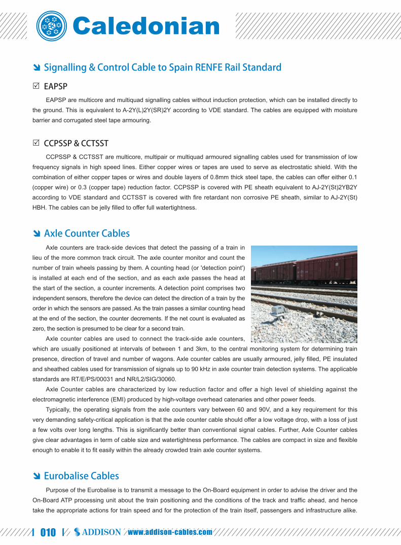
Axle Counter Cables Axle counters are track-side devices that detect the passing of a train in
lieu of the more common track circuit. The axle counter monitor and count the
number of train wheels passing by them. A counting head (or 'detection point')
is installed at each end of the section, and as each axle passes the head at
the start of the section, a counter increments. A detection point comprises two
independent sensors, therefore the device can detect the direction of a train by the
order in which the sensors are passed. As the train passes a similar counting head
at the end of the section, the counter decrements. If the net count is evaluated as
zero, the section is presumed to be clear for a second train.
Axle counter cables are used to connect the track-side axle counters,
which are usually positioned at intervals of between 1 and 3km, to the central monitoring system for determining train
presence, direction of travel and number of wagons. Axle counter cables are usually armoured, jelly fi lled, PE insulated
and sheathed cables used for transmission of signals up to 90 kHz in axle counter train detection systems. The applicable
standards are RT/E/PS/00031 and NR/L2/SIG/30060.
Axle Counter cables are characterized by low reduction factor and offer a high level of shielding against the
electromagnetic interference (EMI) produced by high-voltage overhead catenaries and other power feeds.
Typically, the operating signals from the axle counters vary between 60 and 90V, and a key requirement for this
very demanding safety-critical application is that the axle counter cable should offer a low voltage drop, with a loss of just
a few volts over long lengths. This is signifi cantly better than conventional signal cables. Further, Axle Counter cables
give clear advantages in term of cable size and watertightness performance. The cables are compact in size and fl exible
enough to enable it to fi t easily within the already crowded train axle counter systems.
Eurobalise Cables Purpose of the Eurobalise is to transmit a message to the On-Board equipment in order to advise the driver and the
On-Board ATP processing unit about the train positioning and the conditions of the track and traffi c ahead, and hence
take the appropriate actions for train speed and for the protection of the train itself, passengers and infrastructure alike.

011
Caledonian Railway Cableswww.caledonian-cables.co.uk
The balise cables are used for the Eurobalise and the balise transmission
modules in the On-Board equipment. The cables are flexible, resistant and
have electromagnetic immunity for high frequency communications which is a
necessity for a radio based GSM-R traffi c management system.
These specialised balise cables are to be used in the upgrading of
rail network to meet ERTMS (European Rail Traffic Management System)
requirements. The implementation of ERTMS will facilitate higher-speed services
and an increased number of connections on railways. The balise cables are advanced copper signalling cables which will be
installed along the tracks to carry vital information regarding train position, length and number of wagons. This information will
be used by the Automatic Train Control (ATC) system and relayed both to the driver via transponders, otherwise known as
"balises", and to the train control centre. The balise cables therefore play a vital role in maintaining high levels of safety as the
volume of rail traffi c increases.
Fire Resisting Signalling Cables
K27 Fire Resisting Signalling Cables
K27 are multiconductor halogen free signalling cables, flame retardant according to NF F32-070, fire resistant
according to CR1 CI French standard. The silicon rubber insulated cables are protected with double steel tapes, designed
for suburban infrastructures and underground railways. The cables are used for carrying power control, signals and vital
communication data during the time to evacuate the people at risk.
MD4 Fire Resisting Signalling Cables
MD4 are multiconductor halogen free signalling cables, flame retardant according to NF F32-070, fire resistant
according to CR1 CI French standard. The mica insulated cables are protected with double steel tapes and copper tapes
to offer induction protection, designed for suburban infrastructures and underground railways. The cables are used for
carrying power control, signals and vital communication data during the time to evacuate the people at risk.
Twin Datalink Cables These rail cables are PE or LSZH sheathed interconnecting cables suitable for Solid State Interlocking (SSI)
systems, in either black or blue sheath. The applicable standard is BR1932 (PA05/02833).
Telecom Cables for Outdoor Plant
Trackside Telephone Cable
The trackside telephone cable, usually denoted by RT/ZHLS or A-2Y(L)2Y, are designed primarily for XDSL
transmission in a LAN or access network. Trackside telephone cable are usually unit twin PE insulated jelly fi lled 0.63
or 0.9mm communication cables with either PE or LSZH sheath. The trackside telephone cables are installed in the
cable troughs along the side of the track. The cables can be used to connect everything from stations and relay rooms to
telephone points in location cases. The applicable standards are NR/PS/TEL/00015 (formerly RT/E/PS/00015 and GK/RT
0315) for UK NETWORK RAIL and TS0886/BS 1822 & BR892 for UK NETWORK RAIL, SNCF CT 2328 /SNCF CT 2329
for France RATP. For direct burial application, brass tape armouring or Zetabon type corrugated steel tape armouring can
www.caledonian-cables.co.uk
BASIC DESIGN FOR RAILWAY CABLES

012 www.addison-cables.com
be offered against rodent attack.
Metro Communications Cables
Two metro communications cables are usually employed within railway equipment rooms located in either open
locations or within the tunnels/stations. One is LUL specifi cation G7621 (type 1/non section 12) which is designed for
installation in trackside bracket runs and for use within railway equipment rooms located in open locations. The other,
the LUL specifi cation G7622 (type 2/section 12) metro communications cable is designed for trackside bracket runs, and
railway equipment rooms within subsurface tunnels and stations.
Scada/Pilot Cables
The Scada/Pilot Cable are jelly fi lled 0.9mm multipair telephone cables complying with BS 3573. These telecom
cables are suitable for modem based Supervisory Control and Data Acquisition systems (SCADA) operating in the
VF range 300 to 3000Hz. The SCADA system is radio-based and includes an integrated hardware/software system
that monitors and alarms on the power distribution, escalator status, elevator status, security intrusion, fare collection
intrusion, fi re alarm etc.
The applicable standard is NR/PS/ELP/27220 (formerly RT/E/PS/0034) for UK NETWORK RAIL.
Trackside Fiber Cable
Trackside fi ber cables are fi bre communication cables designed to serve high traffi c and data rate requirements
and FTN applications. To meet the security concerns of tunnels and urban metro system, both metal armoured and all
dielectric optic fi ber cables with up to 144 fi ber counts can be supplied, offering electromagnetic immunity within the rail
network for systems with high traffi c and data requirements. Trackside cables have a single mode fi bre, single continuous
non-metallic strength member, a water-blocking compound, fibre carrier, separator and a PE sheath. The armoured
version usually has corrugated steel/polymer laminate tape for mechanical protection. Compact and cost-effi cient optical
fi ber micro-cables are increasingly being installed in dense railway subway networks. The use of fi ber yarns guarantee
for both longitudinal water tightness and vibration reducing characteristics. The use of premium single mode fibres
guarantees highest data rates and best transmission reliability. Other than corrugated armouring, the metal free all
dielectric fi ber optic cables can be glass armoured with rodent protection or reenforced with double sheath with buffer
intermediate layer.
The applicable standards are NR/PS/TEL/00014 (formerly RT/E/PS/00014), BR 1837 and SCCF CT2242 (corrugated
steel tape armoured) SNCF ST2513 (unarmoured).
Radiating Cables
The radiating cables are another form of coaxial cables to provide a tuned bi-directional desired leakage effect
between transmitter and receiver. The cables are often used in underground, tunnels where an antenna is impossible.
These fl exible perforated coaxial cables act like antenna in this confi ned environment. They are extremely important for
ESTMS/ETCS radio based system.

013
Caledonian Railway Cableswww.caledonian-cables.co.uk
Telecom Cables for Indoor Plant
Armoured F/FTP Cat6 LSZH Cables
Lan cables made up of 4 pair F/FTP Cat6 cables are used to ensure transmission of digital signals between
stations and control centres, feeding information to and from ticket machines, barriers, clocks, display systems, lifts and
escalators. Each pair of these cables are screened with individual aluminium foil, with overall aluminium foil screen. Other
options include UTP (Unshielded), FTP (Overall aluminium foil screened), S/FTP (Individual aluminium foil screened with
overall copper braid screen). The cables are suitable for installation in cable trays or on hooks. Galvanized steel braid
armouring can be applied for rodent protection. The applicable standard is RATP Cat6-K20 for France RATP.
Armoured Optic Fibre LSZH Cables
Using a fiber optic backbone, the communications system is
well connected by fiber optic cables. The communication system
includes public address (PA) systems, emergency telephones, centrally
connected ticket kiosk, closed circuit television monitoring, and controlled
and alarmed access points to the emergency walkways. The PA system
also services the vehicles and the OMSF. The on-board system provides
for announcements of the next station, door closing warnings, and any
service interruptions, as well special announcements about special
events, emergencies, and so on.
The cables are used for long distance telecommunication and signalling links using either single mode or multimode
optical fi bers in suburban infrastructure. These halogen free cables are laid on hooks, pulled through ducts or cables
trays. The applicable standard is RATP K209A/B for France RATP. The cables can be applied with corrugated copolymer
steel armouring for rodent protection.
50/75Ω LSZH Coaxial Cable
The video surveillance system within a station and between stations is made possible with coaxial cables. Analogue
signals from CCTV cameras are transmitted by either 50 or 75Ωn coaxial cables. The 50Ω cables are HF transmission
coaxial cables for GSM antennas. All radio-based communications transmits and receives information relayed through
antennas located along the guideway. The 50Ω cables include: solid red copper; solid copper coated aluminium; red
copper tube; corrugated red copper tube (for 1'5/8F type). The 75Ω cables are HF transmission coaxial cables. These
include solid red copper (for type 11 RTC) used for video surveillance or red copper tube (for type KX6) used for
cameras. The Halogen-free cables are suitable for being laid on hooks, and pulled through walls or through technical
ducts. The applicable standard is RATP K26 for France RATP.
Power & Control Cable for railway applications
450/750V Trackfeeder Cable
At a Substation, the AC current is transformed and rectified into DC 450/750V. Trackfeeder cables are used to
take provide the 450/750 volt DC supply from Traction Substations and Track Paralleling Huts to the track including the
conductor rails, negative cable connections and where appropriate bonding. The single core trackfeeder cable has a
Class 2 stranded aluminium or tinned copper conductor, a PETP (Polyethylene Terephthalate) separator and a black
www.caledonian-cables.co.uk
BASIC DESIGN FOR RAILWAY CABLES

014 www.addison-cables.com
CSP sheath. Positive trackfeeder cables commonly used include 1x1000mm² (aluminium), 1x630mm² (copper) and
1x500 mm²(aluminium). Negative trackfeeder cables commonly used include 1x800mm² (aluminium), 1x500mm² (copper),
1x240mm² (aluminium), 1x161mm² (copper) & 1x150mm² (aluminium). The applicable standard is NR/PS/ELP/21101. BS
6360 and BS 6899 for UK NETWORK RAIL and NF-F5525 for France RATP.
450/750V LSZH Earthing Cable
Earthing cables, commonly named as LSZH 6491B conduit wiring cable, are used
in switch and relay rooms, stations and general areas as required providing an effective
protective earth. These cables are commonly installed in ducts and used in the power
network within a station – from the ticket kiosks, passenger information displays, entrances
and exits to the lifts and escalators. The applicable standards is BS 7211 and EME-
SP-14-026 for UK NETWORK RAIL.
0.6/1KV Steel Wire Armoured LSZH Cable
Steel wire armoured 0.6/1KV LSZH power and auxiliary control cables are designed for supply of power to ticket
kiosks, passenger information displays, entrances and exits, lightning systems, lifts and escalators in the concourse.
They can be installed directly underground, outdoors, indoors and in cable ducting. These cables have Class 2 stranded
copper conductors, XLPE insulation and aluminium or steel wire armour. The applicable standard is BS 6724 and EME-
SP-14-027 for UK NETWORK RAIL. LSZH cables are employed for installation in the concourse where fire, smoke
emission and toxic fumes may create a potential threat during the fi re.
Fire Integrity Cable
Fire Integrity Cable, are designed for installation typically in public help points (PHP), public address (PA), station
announcement platforms (SAP), fi re alarm and CCTV systems, platform screens and door, entrance and exits, lifts and
escalators in a station where vital circuit integrity must be maintained in the event of a fi re. The fi re integrity cables also
furnish a complete fire detection system for difficult environments (like tunnels) providing early warning and no false
alarms. The fire integrity cables consist of solid or stranded copper conductors, silicon rubber insulation, an optional
aluminium tape and a LSZH sheath. The applicable standards include BS 7629-1, BS 5839-1: 2002, BS 8434-1: 2003,
BS EN 50200 PH30, BS 6387 C W Z, IEC 60332-3, IEC 60332-1, BS EN 50265, BS EN 50266, BS 50267, BS EB 50268
, IEC 60754 and IEC 61034). These cables comply with LU Section 12 station regulations.
Aluminum Power Cable
Aluminium power Cables are designed for the distribution of trackside signalling power. These 2 and 4 core power
cables have a sector shaped solid aluminium conductor, XLPE or PVC insulation, a PETP separator and a black PVC
sheath. The applicable standards are BR880, BS 5467 and BS 6346.
Point Heating Cable
Swtichpoints along a railway line allow the train to change between tracks. Many railway switchpoints suffer during
the winter months, from snow and ice blocking the moving rails and point mechanisms, causing failures and disruption
to traffi c. It is vital that these Points continue to operate effectively in adverse weather conditions. To do so, Switchpoint
Heating system are installed in the web of the stock and moving rails and applies heat through point heating cable

015
Caledonian Railway Cableswww.caledonian-cables.co.uk
effectively to the areas most prone to the effects of snow and ice. The point heating cables consist of Class 5 fl exible
tinned copper conductors, EPR (Ethylene Polypropylene Rubber) insulation and a PCP (Polychloroprene) sheath. These
heavy duty cables offer protection from abrasion and mechanical impact whilst maintaining fl exibility to ease installation
and provide power and control in Points Heating systems. The applicable standard is NR/SP/ELP/40045 (formerly RT/E/
PS40045) and BS 7919
Bare Conductor and Screening Conductor Cables
In overhead line networks, screening conductor cables are used to screen telecommunication cables from electrical
interference caused by the potential of a high voltage cable. These cables can absorb the magnetic fi eld generated by the
overhead high voltage cables and minimize the effects of this interference. Bare and covered screening conductor cables
are usually installed in parallel to the communication cable to provide effective zonal screening. The conductor section
is usually 150mm² and 240/250 mm². Screening Conductor Cable has a single core stranded aluminium conductor and
a black PVC or LSZH sheath, and a Bare Conductor consists of a single core stranded aluminium conductor. Screening
conductor cables are denoted as FTN screening conductor cables by NETWORK RAIL. The applicable standard is NR/
PS/TEL/31102 (BR1817)/BS 6485
NSGAFOU Rail Cable
NSGAFOU cables are designed for use in wiring of devices in the electrical traction units that power the wheels
and auxiliary controls (such as breaks and heating systems). NSGAFOU Rail Cable is a single core cable with a Class
5 fl exible tinned copper conductor, EPR insulation, and a Black PCP sheath. These cables are used for existing train
maintenance only.
6.35/11KV, 12.7/22KV & 19/33KV & 25/44KV Medium Voltage Cable
These medium voltage cables are designed for the distribution of three phase A.C. electrical power supplies at
nominal system voltages of 11KV, 22KV 33KV and 44KV to traction substations on D.C. electrified lines. The 25KV
two core concentric cables are mainly used to deliver 25KV single phase electrical power supplies, typically, to feeder
stations on A.C. electrifi ed lines. The 25KV single core cables are mainly used to carry 25KV electrical power supplies
from track-side switching stations to the overhead line equipment on A.C electrifi ed lines. Armoured 11kV cables are used
to distribute power between substations. Over longer distances, 33KV cables are generally specifi ed.
This 11-33kV cables have class 2 stranded plain aluminium or copper conductors, extruded semi-conducting XLPE
conductor screen, XLPE insulation and cold strippable semi-conducting XLPE insulation screen, water blocking tape,
metallic screen of copper wires and copper tapes, aluminium or steel wire armour and a PE, PVC or LSZH sheath.
The applicable standard includes NETWORK RAIL Line Standard NR/PS/ELP/00008, BS 6622 or BS 7835 (LSZH
version). These power cables are available in various sizes: popular sizes of 1x240mm² solid aluminium, 1x185mm² solid
aluminium and 1x300mm² stranded copper are commonly used.
DC Traction Cables for 1500 DC Electrified Lines
Most of the railways use a 1500VDC, single overhead conductor catenary system with traction return via the running
rails. The traction power system provides 1500V DC power to the train through two power rails, a positive and negative,
mounted to the side of the guide beam. The system provided for traction supply from substations connected to lines via
fault sensing circuit breakers. Return current is collected by connecting the substation negative busbar to the rail, usually
by way of impedance bond. DC traction cables are used to connect impedance bonds and negative busbar to rails and
www.caledonian-cables.co.uk
BASIC DESIGN FOR RAILWAY CABLES

016 www.addison-cables.com
between neutral points of the impedance bonds mounted in track. DC
traction cables are designed for traction return for non electrical areas
or electrifi ed areas using 1500DC traction.
DC traction cables are used as positive and negative cables for
railway system. Positive feeder cables connect the dc feeder circuit
breakers in the traction substation to the contact rail system. Negative
feeder cables are used to connect the rectifi er negative bus in the traction
substations to the shunts at the running rail.
In normal traction area, the standard size is 120mm² copper.
This may be provided by 608/0.5mm copper or 925/0.5mm (185 mm²) aluminium. In heavy traction area, standard size is
185mm² copper. This may be provided by 962/0.5mm copper or 1525/0.5mm (300mm²) aluminium.
DC traction cables are characterized by superior aging and stable electrical characteristics at high temperature,
extreme heat resistance and sunlight resistance, suitable for installation in damp locations inside the tunnels. They can
be used for direct burial or in ducts, subject to vibrations of train operation.
Conductor shall be anneal uncoated copper, concentric and round. An extruded semi conducting thermoset
compound shall be applied over the conductor. This conductor shield is fi rmly bonded to the overlying insulation with a
similar temperature coeffi cient of expansion as the EPR insulation. The EPR insulation can withstand oil, heat, stress and
extreme temperature, being moisture, chemical resistant and mechanically rugged. The cables shall have at least 3.9mm
or 155mil insulation thickness. The sheath shall be either crosslinked polyolefin low smoke zero halogen compound
or CSP. The LSZH or CSP sheath applied with this cable provides excellent resistance to mechanical abuse, flame,
weathering, most oils, acids and alkalines.
FIRERAIL Traction Cables for Railway Application FIRERAIL traction cables series are compact single and multicore power and signal cables. They are designed to
pass the fi re tests relevant to railway applications. They have extremely low toxicity values and thanks to the thin wall and
medium-wall design, weight and space requirements are minimized. They are halogen free, flame retardant, low smoke
and have a low toxicity index. Demands for temperature, weathering, ozone and oil resistance are fulfi lled easily. They are
especially suited to electrical/diesel multiples units, railway vehicles, trams and underground railways, for connecting fi xed
and moving parts, open, in cable ducts or pipes, inside and outside railway vehicles, converters, traction motors and breaking
system

017
Caledonian Railway Cableswww.caledonian-cables.co.uk
Cables for Railway Application
Trackside Railway Cables (Intercity Railway)
Equ
ipm
ent s
helte
r
1B
oard
Wiri
ng C
able
s In
Tra
ffic
Con
trol
Cen
ter a
nd E
quip
men
t She
lter
CV
/CV
Z/C
V-S
/CV
Z-S
(Fre
nch
Rai
lway
Sta
ndar
d)
2In
tern
al C
onne
ctio
n C
able
s In
Ser
ver
& C
ontro
l Roo
mZU
G/Z
UT/
SU
G (F
renc
h R
ailw
ay S
tand
ard)
3M
ultic
ore,
Mul
tipai
r or M
ultiq
uad
Trac
ksid
eS
igna
lling
Cab
les
ZPFU
/ ZP
AU
/ ZC
O3
(Fre
nch
Rai
lway
Sta
ndar
d)A
J-2Y
2YD
B2Y
/ A
-2Y
2YB
2Y /
A-2
Y2Y
V /
AJ-
2Y(L
)2Y
DB
2Y
A-2
Y2Y
(L)B
2Y /
A-2
Y(L
)2Y
V (G
erm
an R
ailw
ay S
tand
ard)
E
AP
SP
/ C
CP
SS
P /
CC
TSS
T (S
pani
sh R
ailw
ay S
tand
ard)
SX
CA
V /
SX
CA
G (B
elgi
um R
ailw
ay S
tand
ard)
Loca
l Con
trol a
nd P
ower
Sup
ply
Cab
les
SC
G (F
renc
h R
ailw
ay S
tand
ard)
BR
880
/ SE
902
/ SE
1047
(UK
Rai
lway
Sta
ndar
d)6
Loca
l Sig
nal C
able
sZP
GU
(Fre
nch
Rai
lway
Sta
ndar
d)74
Trac
ksid
e M
ediu
m D
ista
nce
Telc
om C
able
sM
D4
/ RT/
ZHLS
(UK
Rai
lway
Sta
ndar
d)
5S
T251
3BR
/CT2
243
/ CT2
242
(Fre
nch
Rai
lway
Sta
ndar
d)N
R/P
S/T
EL/
0001
4(U
K R
ailw
ay S
tand
ard)
Trac
ksid
e Fi
bre
Opt
ic C
able
s
Sw
itchi
ng C
entre
Cab
les
SW
CLT
(Sw
iss
Rai
lway
Sta
ndar
d)
Bal
isese
Bala
Trac
ksid
e B
ox
Rel
ay R
oom
Fibr
e C
hann
el S
witc
h
Cab
les
Use
d A
long
The
Tra
cksi
de(In
terc
ity R
ailw
ay)
IT R
oom
Net
wor
k M
aint
enan
ce S
erve
r
Trac
ksid
e B
ox
Trac
ksid
e E
quip
men
te
sska
Trde
kE
te
miuq
np
Sw
itchi
ng M
otor
Sw
gt
Mw
oM
inc
gM
go
cro
Axl
e C
ount
erA
lA
xA
er
ut
ue
Co
ee
Enc
oder
8
9
Bal
ise
Cab
les
SP
FB (F
renc
h K
VB
Sys
tem
)E
UR
OB
ALI
SE
SIF
/ E
UR
OB
ALI
SE
BG
A (E
RTM
S S
yste
m)
9
Poi
nt H
eatin
g C
able
s11
Trac
k Fe
eder
Cab
les
13
Rad
iatin
g C
able
s14
DC
Tra
ctio
n C
able
s15
FTN
Scr
eeni
ng C
ondu
ctor
Cab
les
16
Sca
da/P
ilot C
able
s17
Con
duit
Wire
s 18
MV
Pow
er C
able
s19
Loop
Cab
les
20
Sig
nal C
able
s10
ZPFU
(Fre
nch
Rai
lway
Sta
ndar
d)
Cab
le T
ypes
Cab
le C
ode
/ Sta
ndar
dsC
able
Typ
esC
able
Cod
e / S
tand
ards
NR
/SP
/ELP
/400
45 C
able
s (U
K R
ailw
ay S
tand
ard)
K25
NFF
5562
5 (F
renc
h R
ailw
ay S
tand
ard)
RT/
E/S
2110
1 / E
ME
-SP
-14-
025/
SE
908(
UK
Rai
lway
Sta
ndar
d)
EM
E-S
P-1
4-02
6 / S
E26
0L /
SE
774
/ SE
895
(UK
Rai
lway
Sta
ndar
d)
BR
7835
/ B
S66
22 /
NR
/PS
/ELP
/000
08 /
XK
DT
(UK
Rai
lway
Sta
ndar
d)
Axl
e C
ount
er C
able
s12
RT/
F3 (U
K R
ailw
ay S
tand
ard)
K26
(Fre
nch
Rai
lway
Sta
ndar
d)
NR
/PS
TEL/
3110
2 (B
R18
17) (
UK
Rai
lway
Sta
ndar
d)
66
10
11
12
1
2
34
5
16
13
17
1415
1819
20
10
DN
C S
erve
rC
lock
Ser
ver
Net
wor
k C
ente
r
Em
erge
ncy
Han
dlin
g R
oom
Mai
nten
ance
Roo
m
Rai
l
Trac
ksid
e C
hann
el
7
1
12
Bal
ise
Tran
smis
sion
Mod
ule
Traf
fic C
ontr
ol C
entr
eTC
C
CABLES FOR RAILWAY APPLICATION
www.caledonian-cables.co.uk

018 www.addison-cables.com
Trackside Railway Cables (Urban Railway)
Sig
nalli
ng &
Con
trol C
able
sK
23 /
K24
/ K
13 (F
renc
h R
ailw
ay S
tand
ard)
RT/
ZHLS
/ TY
PE
A1
/ A2
/ A3
/ B1
/ B2
/ C1
/ C
2 / C
3 / D
1 / D
2 / E
1 / E
2 / E
3 (U
K R
ailw
ay S
tand
ard)
1
Cop
per T
elec
om C
able
sG
7621
/ G
7622
/ G
7623
(U
K R
ailw
ay S
tand
ard)
DIG
ICO
DE
(Fre
nch
Rai
lway
Sta
ndar
d)2
Fibe
r Opt
ic C
able
sK
209A
/B (F
renc
h R
ailw
ay S
tand
ard)
3
Dat
abus
Cab
les
L120
& K
20 (F
renc
h R
ailw
ay S
tand
ard)
4
Coa
xial
Cab
les
K26
(Fre
nch
Rai
lway
Sta
ndar
d)5Cab
les
Use
d A
long
The
Tra
cksi
de(U
rban
Rai
lway
)
Con
trol R
oom
Met
ro L
ine
/ Lig
ht R
ail /
Rap
id T
rans
it / S
ubw
ay /
Tube
/ U
nder
grou
nd
89
1011
12
12
34 13
67
Cab
le T
rays
/Duc
ts/H
ooks
To s
witc
hes,
sen
sons
, lig
hts
Cam
era
4
5
Hoo
ks o
n Tu
nnel
Way
Sca
da/P
ilot C
able
s7
Dig
icod
e C
able
s12
Twin
Dat
alin
k C
able
s13
Loop
Cab
les
14
Cab
le T
ypes
Cab
le C
ode
/ Sta
ndar
dsC
able
Typ
esC
able
Cod
e / S
tand
ards
Trac
k Fe
eder
Cab
les
6K
25 N
FF55
625
(Fre
nch
Rai
lway
Sta
ndar
d)R
T/E
/S21
101
/ EM
E-S
P-1
4-02
5/S
E90
8 (U
K R
ailw
ay S
tand
ard)
Con
duit
Wire
s 8
EM
E-S
P-1
4-02
6 / S
E26
0L /
SE
774
/ SE
895
(UK
Rai
lway
Sta
ndar
d)
DC
Tra
ctio
n C
able
s10
1800
DC
Pos
itive
/ 300
DC
Neg
ativ
e C
able
s
Loca
l Con
trol o
r Pow
er C
able
s9
SE
902
/ SE
1047
/ B
R88
0 (U
K R
ailw
ay S
tand
ard)
MV
Pow
er C
able
s11
BR
7835
/ B
S66
22 /
NR
/PS
/ELP
/000
08 (U
K R
ailw
ay S
tand
ard)

019
Caledonian Railway Cableswww.caledonian-cables.co.uk
Station Range Railway CablesC
able
s U
sed
In T
he R
ailw
ay S
tatio
n
CC
TV S
urve
illan
ce S
yste
m
PA
Bro
adca
st S
yste
m
Lifts
and
Esc
alat
ors
Em
erge
ncy
Tele
phon
e S
yste
m
Tick
et K
iosk
Rai
lway
Pla
tform
Hel
p P
oint
s
1
13
13
13
4
5
5
5
Ent
ranc
es a
nd E
xits
Tick
et H
alls
Pas
seng
er In
form
atio
n D
ispl
ay
1
1
2 5
6
Con
trol
Roo
m
Plat
form
Stat
ion
Ligh
ting
2
Pla
tform
Scr
eens
and
Doo
rs
Info
rmat
ion
Dis
play
21:3
0
3
Fire
Ala
rm
Ele
vato
r Fla
tform
Cab
les
4
Tele
phon
e C
able
s6
Fire
Res
istin
g C
able
s5
K27
/ M
D4
(Fre
nch
Rai
lway
Sta
ndar
d) E
ME
-SP
-14-
027
/ LU
SE
CTI
ON
12
/ EM
E-S
P-1
4-02
8 (U
K R
ailw
ay S
tand
ard)
8S
E90
2 (U
K R
ailw
ay S
tand
ard)
Con
trol C
able
s
K20
9A/B
(Fre
nch
Rai
lway
Sta
ndar
d)O
ptic
Fib
re C
able
s7
Con
duit
Wire
s 9
SE
260L
/ S
E77
4 / S
E89
5 (U
K R
ailw
ay S
tand
ard)
Coa
xial
Cab
les
2
Dat
a C
able
s3
Fixe
d W
iring
Cab
les
1
K26
(Fre
nch
Rai
lway
Sta
ndar
d)
K20
&L1
20 (F
renc
h R
ailw
ay S
tand
ard)
Cab
le T
ypes
Cab
le C
ode
/ Sta
ndar
dsC
able
Typ
esC
able
Cod
e / S
tand
ards
www.caledonian-cables.co.uk
CABLES FOR RAILWAY APPLICATION

020 www.addison-cables.com
RAILSIG RAILWAY SIGNALLING & CONTROL CABLES
Equipment Cables for Control Centre
France RATP Railway Standard
Multicore Signalling & Control Main Cables for Trackside
German DB Railway StandardUK NETWORK RAIL StandardSpain RENFE Railway Standard
Multipair/Multiquad Signalling & Control Cables for Trackside
German DB Railway StandardFrance RATP Railway Standard Intercity Main LinesFrance RATP Railway Standard Urban SubwaySpain RENFE Railway StandardBelgium SNCB Railway StandardSwiss SBB Railway StandardUK NETWORK RAIL Standard
Axle Counter Cables
UK NETWORK RAIL Standard
Balise Cables
French KVB SystemEuropean ERTMS System
Fire lntegrity Cables
France RATP Railway Standard

021
Caledonian Railway Cableswww.caledonian-cables.co.uk
CV /CVZ Indoor Equipment Cables
Applications The cables are used as cabling wires for the relays and electronic equipments
in the Traffi c Control Center and Trackside Equipment Shelter. The CV cables are
suitable for use only in Optical Control Panel (OCP) wiring.
Standards SNCF CT 500 ●
Construction ● Conductors: Class 5 stranded tinned
copper (for flexible wires CV-S & CVZ-S type),
class 1 solid tinned copper (for stiff wires CV &
CVZ), 0.5/1.0/2.5/6.0 mm² cross section.
● Insulation: White (for CVZ type)/coloured
(for CV type) unleaded PVC.
● Sheath: Coloured polyamide outer sheath (for CVZ & CVZ-S type).
Electrical Characteristics at 20℃ CV/CVZ
Nominal Conductor Diameter mm 0.8 1.17 1.78Nominal Cross Section Area mm² 0.5 1.0 2.5Maximum Conductor Resistance (DC) Ω/km 36.1 17.9 7.56Operating Voltage V 750
CV-S/CVZ-SNo of Strands/ Strand Diameter No/mm 16/0.2 32/0.2 50/0.25 84/0.3Nominal Cross Section Area mm² 0.5 1.0 2.5 6Maximum Conductor Resistance (DC) Ω/km 40.1 20.0 8.21 3.39Operating Voltage V 750
Mechanical and Thermal Properties ● Minimum Bending Radius (static): 4×OD (for fl exible wire); 5×OD (for stiff wire)
● Minimum Bending Radius (dynamic): 8×OD (for fl exible wire); 10×OD (for stiff wire)
● Operating Temperature: -15℃ to +70℃
Solid/Stranded Tinned Copper Conductor
PVC Insulation
Polymide Sheath
RAILSIG RAILWAY SIGNALLING & CONTROL CABLES
Equipment Cables for Control Centre France RATP Railway Standard

022 www.addison-cables.com
Dimensions and Weight CV/CVZ Cables
Cable Code Number of Conductors
Nominal Sheath Thicknessmm
Nominal Overall Diametermm
Nominal Weightkg/km
0.8mm Conductor, 1.6mm Insulated WireRS/CV-075-Y-1G0.5 1 - - 6
1.17mm Conductor, 1.9mm Insulated WireRS/CVZ-075-Y(4Y)-1G1 1 0.2 2.3 13.2
1.78mm Conductor, 2.7mm Insulated WireRS/CVZ-075-Y(4Y)- 1G2.5 1 0.2 3.1 29.3
CV-S/CVZ-S Cables
Cable Code Number of Conductors
Nominal Sheath Thicknessmm
Nominal Overall Diametermm
Nominal Weightkg/km
16/0.2mm Conductor, 1.6mm Insulated WireRS/CV-S-075-Y-1G0.5 1 - - 6.8RS/CVZ-S-075-Y(4Y)-1G0.5 1 0.35 2.3 7.6
32/0.2mm Conductor, 2.1mm Insulated WireRS/CVZ-S-075-Y(4Y)-1G1 1 0.2 2.5 13.5RS/CVZ-S-075-Y(4Y)-1P1S 1P 0.2 2.5 28.2
50/0.25mm Conductor, 3.0mm Insulated WireRS/CVZ-S-075-Y(4Y)- 1G2.5 1 0.2 3.4 29.3
84/0.3mm Conductor, 4.2mm Insulated WireRS/CVZ-S-075- Y(4Y)-1G6 1 0.2 4.6 60.1
AbrasionRetardant
Resistant to HighTemperature
0°
Weather Resistant Mineral Oil Resistant
Rated voltage
450/750V
Flame RetardantNF C32-070-2.1(C2)
IEC 60332-1/EN 50265-2-1

023
Caledonian Railway Cableswww.caledonian-cables.co.uk
ZUG/ ZUT/ SUG Indoor Equipment Cables
Applications The cables are used as cabling for the relays and electronic equipments
in the Traffic Control Center and Trackside Equipment Shelter. The cables are
suitable for indoor interconnection of railway network equipments.
Standards SNCF CT 455 ●
Construction ● Conductors: Class 5 stranded tinned copper,
1 mm² or 0.38 mm² cross section.
● Insulation: Coloured PVC.
● Cabling Element: Pairs (for ZUG/ZUT)/Cores (for SUG).
● Core Wrapping (optional): Plastic tape(s) with overlapping.
● Screen (optional): Tinned copper braid for electrostatic protection (only for ZUT type).
● Sheath: Black FRPVC compound. LSZH option can be offered upon request.
Electrical Characteristics at 20℃ No of Strands/ Strand Diameter No/mm 12/0.2 32/0.2Nominal Cross Section Area mm² 0.38 1Maximum Conductor Resistance (DC) Ω/km 52.5 20.1Operating Voltage V 450/750 450/750
Mechanical and Thermal Properties ● Minimum Bending Radius: 4×OD (static); 8×OD (dynamic)
● Operating Temperature: -15℃ to +70℃
Dimensions and Weight ZUG Cables
Cable Code Number of Pairs Nominal Sheath Thicknessmm
Nominal Overall Diametermm
Nominal Weightkg/km
12/0.2mm Conductor, 1.4mm Insulated WireRS/ZUG-075-YY-28P0.38S 28 0.7 15.7 310
32/0.2mm Conductor, 2.09mm Insulated WireRS/ZUG-075-YY-1P1S 1 0.7 7.0 59
Stranded Tinned Copper Conductor
PVC Insulation
Twisted Pair
Non Hygroscopic Tape
FRPVC/LSZH Sheath
RAILSIG RAILWAY SIGNALLING & CONTROL CABLES
Equipment Cables for Control Centre France RATP Railway Standard

024 www.addison-cables.com
Cable Code Number of Pairs Nominal Sheath Thicknessmm
Nominal Overall Diametermm
Nominal Weightkg/km
RS/ZUG-075-YY-3P1S 3 0.7 9.9 108RS/ZUG-075-YY-6P1S 6 0.7 12.4 184RS/ZUG-075-YY-12P1S 12 0.7 15.7 335
SUG Cables
Cable Code Number of Conductors
Nominal Sheath Thicknessmm
Nominal Overall Diametermm
Nominal Weightkg/km
32/0.2mm Conductor, 2.09mm Insulated WireRS/SUG-075-YY-3C1S 3 0.7 8 73
ZUT Cables
Cable Code Number of Pairs Nominal Sheath Thicknessmm
Nominal Overall Diametermm
Nominal Weightkg/km
32/0.2mm Conductor, 2.09mm Insulated WireRS/ZUT-075-YCY-2P1S 2 0.7 9.5 122RS/ZUT-075-YCY-6P1S 6 0.7 13.5 276RS/ZUT-075-YCY-12P1S 12 0.7 17.5 445
Rated voltage
450/750V
Laid In Cable Tray Flame RetardantNF C32-070-2.1(C2)
IEC 60332-1/EN 50265-2-1

025
Caledonian Railway Cableswww.caledonian-cables.co.uk
SCG Local Control Cables
Applications The cables are designed as local control or power supply cables for trackside
and between the rails equipments inside the equipment shelter.
Standards SNCF CT 466 ●
Construction ● Conductors: Class 1 tinned solid copper.
● Insulation: Cross-linked black polyethylene (XLPE)
insulation.
● Sheath: PVC sheath, coloured black.
Electrical Characteristic s at 20℃ Nominal Conductor Diameter mm 1.78 2.76Nominal Cross Section Area mm² 2.5 6Maximum Conductor Resistance (DC) Ω/km 7.56 3.11Operating Voltage V 750
Mechanical and Thermal Properties ● Minimum Bending Radius: 5×OD (static); 10×OD (dynamic)
● Operating Temperature: -20℃ to +90℃
Dimensions and Weight
Cable Code Number of Cores Nominal Sheath Thicknessmm
Nominal Overall Diametermm
Nominal Weightkg/km
1.78mm Conductor, 4mm Insulated WireRS/SCG-075-2XY-2G2.5 2 3.0 14 227RS/SCG-075-2XY-4G2.5 4 3.2 17 336RS/SCG-075-2XY-6G2.5 6 3.7 19.5 475RS/SCG-075-2XY-8G2.5 8 3.9 21 542
2.76mm Conductor, 5.4mm Insulated WireRS/SCG-075-2XY-2G6 2 3.6 18 384RS/SCG-075-2XY-4G6 4 3.7 20.5 550RS/SCG-075-2XY-6G6 6 3.9 23.5 780RS/SCG-075-2XY-8G6 8 4.1 26 940
Cross-linked PE Insulation
Solid Copper Conductor
PVC Sheath
Rated voltage
450/750V
Laid In Cable Tray Flame RetardantNF C32-070-2.1(C2)
IEC 60332-1/EN 50265-2-1
RAILSIG RAILWAY SIGNALLING & CONTROL CABLES
Equipment Cables for Control Centre France RATP Railway Standard

026 www.addison-cables.com
AJ-2Y2YDB2Y S(H115)/S(H145)/S(H95)
Applications The cables are designed for transmission of service tensions up to 600 VDC /
420 Veff AC100Hz in railway signalling networks, and are suitable for installation in
ducts or laying directly into the ground.
Standards Dlk 1.013.107y ●
Dlk 1.013.107y ●
Dlk 1.013.108y (for 1.4/1.8mm conductor H95 type) ●
Dlk 1.013.110y ●
Construction Conductors: Solid annealed copper, 0.9, ●
1.4 or 1.8 mm nominal diameter.
Insulation: Solid polyethylene. ●
Stranding: Single conductors are helically ●
stranded in concentric layers. Cables from 14
conductors on have two extra conductors of 0.5mm with perforated insulation (surveillance conductors).
Core Wrapping: Plastic tape(s) with overlapping. ●
Inner Sheath: Low density polyethylene. ●
Electrostatic Shield: One layer of helically applied copper wires (0.9, 1.2, 1.4 or 1.8mm). ●
Electromagnetic Shield: Two helically applied steel tapes (0.5 or 0.8mm thick, depending on required reduction ●
factor).
Outer Sheath: Low density polyethylene. ●
Type Codes AJ- outdoor cable with protection against inductive infl uences
2Y solid PE conductor insulation
2Y inner PE sheath
D copper wire concentric screen
B steel tape armor
2Y outer PE sheath
S signal cable
LG layer stranding
H (n) operating capacity
Copper WireSolid PE InsulationNon Hygroscopic TapeInner PE SheathExtra Perforated Insulated Conductor
Solid Copper ConductorPE Sheath
Double Steel Tapes

027
Caledonian Railway Cableswww.caledonian-cables.co.uk
Electrical Characteristics at 20 ℃ Nominal Conductor Diameter mm 0.9 1.4 1.8Maximum Conductor Resistance Ω/km 28.9 11.9 7.2Minimum Insulation Resistance @500 V DC (1min) MΩ.km 10000 10000 10000Maximum Mutual Capacitance @800Hz (AC) nF/km 115 145/95* 145/95*Dielectric Strength, conductor to conductor (DC voltage 1min) V 3535 3535 3535Surveillance Conductors
Loop resistance, maximum Ω/km 190 190 190Insulation resistance
- dry cable core, minimum MΩ.km 1000 1000 1000- wet cable core, maximum KΩ.km 30 30 30
Nominal Reduction Factor @ 100 V/km, 16 2/3 Hzrk 401 series 0.15 0.15 0.15rk 501 series 0.35 0.35 0.35rk 601 series 0.55 0.55 0.55
Operating Voltage AC/DC V 420/600 420/600 420/600Test Voltage@50 Hz 1 min
Core to Core Veff 2500 2500 2500Core to Screen Veff 2500 2500 2500
*The value “95” is only for cables with 1.4/1.8mm conductors according to Dlk 1.013.108y.
Mechanical and Thermal Properties ● Minimum Bending Radius: 10×OD
● Temperature Range: -40℃ to +60℃ (during operation); -10℃ +60℃ (during installation)
Dimensions and Weight AJ-2Y2YDB2Y n×1×0.9 S(H115)
Cable CodeNumber of conductors
(n)
Nominal Sheath Thicknessmm
Nominal Overall Diameter
mm
Nominal Weightkg/kmInner Outer
0.9mm Conductor, 1.55mm Insulated Wire rk 601 Series RS107y-2Y2YDB2Y-10C0.9-S(H115)-R6 10 1.3 1.2 19.0 520RS107y-2Y2YDB2Y-20C0.9-S(H115)-R6 20 1.3 1.2 20.0 650RS107y-2Y2YDB2Y-30C0.9-S(H115)-R6 30 1.3 1.2 22.0 780RS107y-2Y2YDB2Y-50C0.9-S(H115)-R6 50 1.3 1.2 25.0 1010RS107y-2Y2YDB2Y-80C0.9-S(H115)-R6 80 1.3 1.2 29.0 1330RS107y-2Y2YDB2Y-120C0.9-S(H115)-R6 120 1.3 1.3 32.0 1740RS107y-2Y2YDB2Y-160C0.9-S(H115)-R6 160 1.3 1.3 35.0 2310RS107y-2Y2YDB2Y-200C0.9-S(H115)-R6 200 1.3 1.3 38.0 2520
0.9mm Conductor, 1.55mm Insulated Wire rk 501 SeriesRS107y-2Y2YDB2Y-10C0.9-S(H115)-R5 10 1.3 1.2 19.0 600RS107y-2Y2YDB2Y-20C0.9-S(H115)-R5 20 1.3 1.2 20.0 740RS107y-2Y2YDB2Y-30C0.9-S(H115)-R5 30 1.3 1.2 22.0 890RS107y-2Y2YDB2Y-50C0.9-S(H115)-R5 50 1.3 1.3 25.0 1150RS107y-2Y2YDB2Y-80C0.9-S(H115)-R5 80 1.3 1.3 29.0 1480RS107y-2Y2YDB2Y-120C0.9-S(H115)-R5 120 1.5 1.3 32.0 1910RS107y-2Y2YDB2Y-160C0.9-S(H115)-R5 160 1.5 1.3 35.0 2530RS107y-2Y2YDB2Y-200C0.9-S(H115)-R5 200 1.5 1.5 38.0 2730
RAILSIG RAILWAY SIGNALLING & CONTROL CABLES
Multicore Signalling & Control Main Cables for Trackside German DB Railway Standard

028 www.addison-cables.com
AJ-2Y2YDB2Y n×1×1.4/1.8 S(H145)
Cable CodeNumber of conductors
(n)
Nominal Sheath Thicknessmm
Nominal Overall Diameter
mm
Nominal Weightkg/kmInner Outer
1.4mm Conductor, 2.2mm Insulated Wire rk 601 SeriesRS107y-2Y2YDB2Y-10C1.4-S(H145)-R6 10 1.3 1.2 21 670RS107y-2Y2YDB2Y-20C1.4-S(H145)-R6 20 1.3 1.2 23.5 940RS107y-2Y2YDB2Y-30C1.4-S(H145)-R6 30 1.3 1.2 27 1180RS107y-2Y2YDB2Y-50C1.4-S(H145)-R6 50 1.3 1.2 31 1650RS107y-2Y2YDB2Y-80C1.4-S(H145)-R6 80 1.3 1.2 35 2270RS107y-2Y2YDB2Y-120C1.4-S(H145)-R6 120 1.3 1.3 41 3110RS107y-2Y2YDB2Y-160C1.4-S(H145)-R6 160 1.3 1.3 46 3900RS107y-2Y2YDB2Y-200C1.4-S(H145)-R6 200 1.3 1.3 49 4670
1.4mm Conductor, 2.2mm Insulated Wire rk 501 SeriesRS107y-2Y2YDB2Y-10C1.4-S(H145)-R5 10 1.3 1.2 21 780RS107y-2Y2YDB2Y-20C1.4-S(H145)-R5 20 1.3 1.2 23.5 1070RS107y-2Y2YDB2Y-30C1.4-S(H145)-R5 30 1.3 1.2 26 1320RS107y-2Y2YDB2Y-50C1.4-S(H145)-R5 50 1.3 1.3 31 1810RS107y-2Y2YDB2Y-80C1.4-S(H145)-R5 80 1.3 1.3 35 2460RS107y-2Y2YDB2Y-120C1.4-S(H145)-R5 120 1.5 1.3 42 3380RS107y-2Y2YDB2Y-160C1.4-S(H145)-R5 160 1.5 1.3 46 4190RS107y-2Y2YDB2Y-200C1.4-S(H145)-R5 200 1.5 1.5 49 5000
1.4mm Conductor, 2.2mm Insulated Wire rk 401 SeriesRS107y-2Y2YDB2Y-10C1.4-S(H145)-R4 10 1.3 1.2 23 960RS107y-2Y2YDB2Y-20C1.4-S(H145)-R4 20 1.3 1.2 25.6 1260RS107y-2Y2YDB2Y-30C1.4-S(H145)-R4 30 1.3 1.3 28 1940RS107y-2Y2YDB2Y-50C1.4-S(H145)-R4 50 1.3 1.3 33 2450RS107y-2Y2YDB2Y-80C1.4-S(H145)-R4 80 1.5 1.3 38 3280RS107y-2Y2YDB2Y-120C1.4-S(H145)-R4 120 1.5 1.5 44 4290RS107y-2Y2YDB2Y-160C1.4-S(H145)-R4 160 1.5 1.5 48 5200RS107y-2Y2YDB2Y-200C1.4-S(H145)-R4 200 1.5 1.5 52 6060
1.8mm Conductor, 2.7mm Insulated Wire rk 601 SeriesRS107y-2Y2YDB2Y-10C1.8-S(H145)-R6 10 1.3 1.2 23 850RS107y-2Y2YDB2Y-20C1.8-S(H145)-R6 20 1.3 1.2 27 1260RS107y-2Y2YDB2Y-30C1.8-S(H145)-R6 30 1.3 1.3 30 1620RS107y-2Y2YDB2Y-50C1.8-S(H145)-R6 50 1.3 1.3 36 2080RS107y-2Y2YDB2Y-80C1.8-S(H145)-R6 80 1.5 1.3 41 3310RS107y-2Y2YDB2Y-120C1.8-S(H145)-R6 120 1.5 1.5 48 4570RS107y-2Y2YDB2Y-160C1.8-S(H145)-R6 160 1.5 1.5 54 5950RS107y-2Y2YDB2Y-200C1.8-S(H145)-R6 200 1.5 1.5 58 6970
1.8mm Conductor, 2.7mm Insulated Wire rk 501 SeriesRS107y-2Y2YDB2Y-10C1.8-S(H145)-R5 10 1.3 1.2 23 970RS107y-2Y2YDB2Y-20C1.8-S(H145)-R5 20 1.3 1.2 27 1410RS107y-2Y2YDB2Y-30C1.8-S(H145)-R5 30 1.3 1.3 30 1780RS107y-2Y2YDB2Y-50C1.8-S(H145)-R5 50 1.3 1.3 36 2520RS107y-2Y2YDB2Y-80C1.8-S(H145)-R5 80 1.5 1.3 42 3570RS107y-2Y2YDB2Y-120C1.8-S(H145)-R5 120 1.5 1.5 49 5950RS107y-2Y2YDB2Y-160C1.8-S(H145)-R5 160 1.5 1.5 55 6170RS107y-2Y2YDB2Y-200C1.8-S(H145)-R5 200 1.5 1.5 59 7380
1.8mm Conductor, 2.7mm Insulated Wire rk 401 SeriesRS107y-2Y2YDB2Y-10C1.8-S(H145)-R4 10 1.3 1.2 25 1160RS107y-2Y2YDB2Y-20C1.8-S(H145)-R4 20 1.3 1.2 29 1700RS107y-2Y2YDB2Y-30C1.8-S(H145)-R4 30 1.3 1.3 32 2400RS107y-2Y2YDB2Y-50C1.8-S(H145)-R4 50 1.3 1.3 38 3350RS107y-2Y2YDB2Y-80C1.8-S(H145)-R4 80 1.5 1.3 44 3310RS107y-2Y2YDB2Y-120C1.8-S(H145)-R4 120 1.5 1.5 51 4900RS107y-2Y2YDB2Y-160C1.8-S(H145)-R4 160 1.5 1.5 57 7340RS107y-2Y2YDB2Y-200C1.8-S(H145)-R4 200 1.5 1.5 61 8650

029
Caledonian Railway Cableswww.caledonian-cables.co.uk
AJ-2Y2YDB2Y n×1×1.4/1.8 S(H95)
Cable CodeNumber of conductors
(n)
Nominal Sheath Thickness
mmNominal Overall
Diametermm
Nominal Weightkg/km
Inner Outer1.4mm Conductor, 2.7mm Insulated Wire rk 501 Series
RS108y-2Y2YDB2Y-10C1.4-S(H95)-R5 10 1.3 1.2 22.0 900RS108y-2Y2YDB2Y-14C1.4-S(H95)-R5 14 1.3 1.2 24.0 1010RS108y-2Y2YDB2Y-20C1.4-S(H95)-R5 20 1.3 1.2 27.0 1220RS108y-2Y2YDB2Y-30C1.4-S(H95)-R5 30 1.3 1.2 30.0 1520RS108y-2Y2YDB2Y-50C1.4-S(H95)-R5 50 1.3 1.3 35.0 2090
1.4mm Conductor, 2.7mm Insulated Wire rk 401 SeriesRS108y-2Y2YDB2Y-30C1.4-S(H95)-R4 30 1.3 1.2 32.0 2150RS108y-2Y2YDB2Y-50C1.4-S(H95)-R4 50 1.3 1.3 38.0 2900
1.8mm Conductor, 3.4mm Insulated Wire rk 501 SeriesRS108y-2Y2YDB2Y-10C1.8-S(H95)-R5 10 1.3 1.2 25.0 1130RS108y-2Y2YDB2Y-14C1.8-S(H95)-R5 14 1.3 1.2 27.0 1330RS108y-2Y2YDB2Y-20C1.8-S(H95)-R5 20 1.3 1.2 30.0 1620RS108y-2Y2YDB2Y-30C1.8-S(H95)-R5 30 1.3 1.3 34.0 2340RS108y-2Y2YDB2Y-50C1.8-S(H95)-R5 50 1.3 1.3 42.0 3020
1.8mm Conductor, 3.4mm Insulated Wire rk 401 SeriesRS108y-2Y2YDB2Y-30C1.8-S(H95)-R4 30 1.3 1.3 37.0 2880RS108y-2Y2YDB2Y-50C1.8-S(H95)-R4 50 1.3 1.3 44.0 3950
Anti Induction
EMIUV Resistant Water Resistant Rated Voltage
600V DC/420V AC
Laid In Ducts Buried in Ciround Zero HalogenIEC 60754-1/NF C20-454
EN 50267-2-1
Zero
RAILSIG RAILWAY SIGNALLING & CONTROL CABLES
Multicore Signalling & Control Main Cables for Trackside German DB Railway Standard
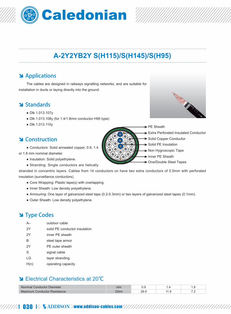
030 www.addison-cables.com
A-2Y2YB2Y S(H115)/S(H145)/S(H95)
Applications The cables are designed in railways signalling networks, and are suitable for
installation in ducts or laying directly into the ground.
Standards Dlk 1.013.107y ●
Dlk 1.013.108y (for 1.4/1.8mm conductor H95 type) ●
Dlk 1.013.110y ●
Construction Conductors: Solid annealed copper, 0.9, 1.4 ●
or 1.8 mm nominal diameter.
Insulation: Solid polyethylene. ●
Stranding: Single conductors are helically ●
stranded in concentric layers. Cables from 14 conductors on have two extra conductors of 0.5mm with perforated
insulation (surveillance conductors).
Core Wrapping: Plastic tape(s) with overlapping. ●
Inner Sheath: Low density polyethylene. ●
Armouring: One layer of galvanized steel tape (0.2-0.3mm) or two layers of galvanized steel tapes (0.1mm). ●
Outer Sheath: Low density polyethylene. ●
Type Codes A– outdoor cable
2Y solid PE conductor insulation
2Y inner PE sheath
B steel tape armor
2Y PE outer sheath
S signal cable
LG layer stranding
H(n) operating capacity
Electrical Characteristics at 20 ℃ Nominal Conductor Diameter mm 0.9 1.4 1.8Maximum Conductor Resistance Ω/km 28.9 11.9 7.2
Solid PE Insulation
Non Hygroscopic Tape
Inner PE Sheath
Extra Perforated Insulated Conductor
Solid Copper Conductor
PE Sheath
One/Double Steel Tapes

031
Caledonian Railway Cableswww.caledonian-cables.co.uk
Minimum Insulation Resistance @500 V DC (1min) MΩ.km 10000 10000 10000Maximum Conductor Capacitance @800Hz (AC) nF/km 115 145/95* 145/95*Dielectric Strength, conductor to conductor (DC voltage 1min) V 3535 3535 3535
Surveillance ConductorsLoop resistance, maximum Ω/km 190 190 190Insulation resistance
- dry cable core, minimum MΩ.km 1000 1000 1000- wet cable core, maximum KΩ.km 30 30 30
Operating Voltage AC/DC V 420/600 420/600 420/600Test Voltage@50 Hz 1 min
Core to Core Veff 2500 2500 2500Core to Screen Veff 2500 2500 2500
*The value “95” is only for cables with 1.4/1.8mm conductors according to Dlk 1.013.108y.
Mechanical and Thermal Properties ● Minimum Bending Radius: 10×OD
● Temperature Range: -40℃ to +60℃ (during operation); -10℃ +60℃ (during installation)
Dimensions and Weight A-2Y2YB2Y n×1× 0.9 S(H115)
Cable CodeNumber of conductors
(n)
Nominal Sheath Thickness mm
Nominal Overall Diameter
mm
Nominal Weightkg/kmInner Outer
0.9mm Conductor, 1.55mm Insulated WireRS107y-2Y2YB2Y-2C0.9-S(H115) 2 1.3 1.2 12.0 120RS107y-2Y2YB2Y-4C0.9-S(H115) 4 1.3 1.2 13.0 140RS107y-2Y2YB2Y-7C0.9-S(H115) 7 1.3 1.2 14.0 170RS107y-2Y2YB2Y-10C0.9-S(H115) 10 1.3 1.2 15.5 220RS107y-2Y2YB2Y-14C0.9-S(H115) 14 1.3 1.2 16.0 260RS107y-2Y2YB2Y-20C0.9-S(H115) 20 1.3 1.2 17.0 320RS107y-2Y2YB2Y-24C0.9-S(H115) 24 1.3 1.2 19.0 370RS107y-2Y2YB2Y-30C0.9-S(H115) 30 1.3 1.2 19.0 410RS107y-2Y2YB2Y-40C0.9-S(H115) 40 1.3 1.2 20.0 500RS107y-2Y2YB2Y-50C0.9-S(H115) 50 1.3 1.2 22.0 590RS107y-2Y2YB2Y-60C0.9-S(H115) 60 1.3 1.2 23.0 680RS107y-2Y2YB2Y-80C0.9-S(H115) 80 1.3 1.2 25.0 840RS107y-2Y2YB2Y-100C0.9-S(H115) 100 1.3 1.3 28.0 1020RS107y-2Y2YB2Y-120C0.9-S(H115) 120 1.3 1.3 29.0 1180RS107y-2Y2YB2Y-140C0.9-S(H115) 140 1.3 1.3 31.0 1360
A-2Y2YB2Y n×1×1.4/1.8 S(H145)
Cable CodeNumber of conductors
(n)
Nominal Sheath Thickness mm
Nominal Overall Diameter
mm
Nominal Weightkg/km
Inner Outer1.4mm Conductor, 2.2mm Insulated Wire
RS107y-2Y2YB2Y-4C1.4-S(H145) 4 1.3 1.2 14.0 190RS107y-2Y2YB2Y-7C1.4-S(H145) 7 1.3 1.2 15.5 260RS107y-2Y2YB2Y-10C1.4-S(H145) 10 1.3 1.2 18.0 340RS107y-2Y2YB2Y-14C1.4-S(H145) 14 1.3 1.2 19.0 420RS107y-2Y2YB2Y-20C1.4-S(H145) 20 1.3 1.2 21.0 550RS107y-2Y2YB2Y-24C1.4-S(H145) 24 1.3 1.2 22.0 630
RAILSIG RAILWAY SIGNALLING & CONTROL CABLES
Multicore Signalling & Control Main Cables for Trackside German DB Railway Standard

032 www.addison-cables.com
Cable CodeNumber of conductors
(n)
Nominal Sheath Thickness mm
Nominal Overall Diameter
mm
Nominal Weightkg/km
Inner OuterRS107y-2Y2YB2Y-30C1.4-S(H145) 30 1.3 1.2 23.0 750RS107y-2Y2YB2Y-40C1.4-S(H145) 40 1.3 1.2 25.0 940RS107y-2Y2YB2Y-50C1.4-S(H145) 50 1.3 1.3 28.0 1140RS107y-2Y2YB2Y-60C1.4-S(H145) 60 1.3 1.3 30.0 1320
1.8mm Conductor, 2.7mm Insulated WireRS107y-2Y2YB2Y-4C1.8-S(H145) 4 1.3 1.2 15.5 250RS107y-2Y2YB2Y-7C1.8-S(H145) 7 1.3 1.2 17.0 350RS107y-2Y2YB2Y-10C1.8-S(H145) 10 1.3 1.2 20.0 470RS107y-2Y2YB2Y-14C1.8-S(H145) 14 1.3 1.2 21.0 600RS107y-2Y2YB2Y-20C1.8-S(H145) 20 1.3 1.2 24.0 800RS107y-2Y2YB2Y-24C1.8-S(H145) 24 1.3 1.2 26.0 910RS107y-2Y2YB2Y-30C1.8-S(H145) 30 1.3 1.2 27.0 1100RS107y-2Y2YB2Y-40C1.8-S(H145) 40 1.3 1.2 30.0 1400
A-2Y2YB2Y n×1×1.4 S(H95)
Cable CodeNumber of conductors
(n)
Nominal Sheath Thickness mm
Nominal Overall Diameter
mm
Nominal Weightkg/km
Inner Outer1.4mm Conductor, 2.7mm Insulated Wire
RS108y-2Y2YB2Y-10C1.4-S(H95) 10 1.3 1.2 18.0 390RS108y-2Y2YB2Y-14C1.4-S(H95) 14 1.3 1.2 20.0 480RS108y-2Y2YB2Y-20C1.4-S(H95) 20 1.3 1.2 22.0 610
1.8mm Conductor, 3.4mm Insulated WireRS108y-2Y2YB2Y-10C1.8-S(H95) 10 1.3 1.2 21.0 550RS108y-2Y2YB2Y-14C1.8-S(H95) 14 1.3 1.2 23.0 700
UV Resistant Water Resistant Rated Voltage
600V DC/420V AC
Laid In Ducts Buried in Ciround Zero HalogenIEC 60754-1/NF C20-454
EN 50267-2-1
Zero

033
Caledonian Railway Cableswww.caledonian-cables.co.uk
A-2Y2Yv S(H115)/S(H145)/S(H95)
Applications The cables are designed for general uses in protective devises in railways
signalling networks, and are suitable for installation in ducts.
Standards Dlk 1.013.107y ●
Dlk 1.013.108y (for 1.4/1.8mm conductor H95 type) ●
Dlk 1.013.110y ●
Construction Conductors: Solid annealed copper, 0.9, 1.4 or ●
1.8 mm nominal diameter.
Insulation: Solid polyethylene. ●
Stranding: Single conductors are helically stranded in concentric layers. Cables from 14 conductors on, have two ●
extra conductors with perforated insulation (surveillance conductors).
Core Wrapping: Plastic tape(s) with overlapping. ●
Outer Sheath: Low density polyethylene. ●
Type Codes A– outdoor cable
2Y solid PE conductor insulation
2Yv PE sheath with increased wall thickness
S signal cable
LG layer stranding
H(n) operating capacity
Electrical Characteristics at 20 ℃ Nominal Conductor Diameter mm 0.9 1.4 1.8Maximum Conductor Resistance Ω/km 28.9 11.9 7.2Minimum Insulation Resistance @500 V DC (1min) MΩ.km 10000 10000 10000Maximum Conductor Capacitance @800Hz (AC) nF/km 115 145/95* 145/95*Dielectric Strength, conductor to conductor (DC voltage 1min) V 3535 3535 3535Surveillance Conductors
Loop resistance, maximum Ω/km 190 190 190Insulation resistance
- dry cable core, minimum MΩ.km 1000 1000 1000
Solid PE Insulation
Non Hygroscopic Tape
Extra Perforated Insulated Conductor
Solid Copper Conductor
Outer PE Sheath
RAILSIG RAILWAY SIGNALLING & CONTROL CABLES
Multicore Signalling & Control Main Cables for Trackside German DB Railway Standard

034 www.addison-cables.com
- wet cable core, maximum KΩ.km 30 30 30Operating Voltage AC/DC V 420/600 420/600 420/600Test Voltage@50 Hz 1 min
Core to Core Veff 2500 2500 2500Core to Screen Veff 2500 2500 2500
*The value “95” is only for cables with 1.4/1.8mm conductors according to Dlk 1.013.108y.
Mechanical and Thermal Properties Minimum Bending Radius: 7.5×OD ●
Temperature Range: -40℃ to +60℃ (during operation); -10℃ to +60℃ (during installation) ●
Dimensions and Weight A-2Y2Yv n×1×0.9 S(H115)
Cable CodeNumber of conductors
(n)
Nominal Sheath Thickness
mm
Nominal Overall Diameter
mm
Nominal Weightkg/km
0.9mm Conductor, 1.55mm Insulated WireRS107y-2Y2Yv-2C0.9-S(H115) 2 2.0 9.0 60RS107y-2Y2Yv-4C0.9-S(H115) 4 2.0 9.0 75RS107y-2Y2Yv-7C0.9-S(H115) 7 2.0 11.0 100RS107y-2Y2Yv-10C0.9-S(H115) 10 2.0 12.0 130RS107y-2Y2Yv-14C0.9-S(H115) 14 2.0 13.0 170RS107y-2Y2Yv-20C0.9-S(H115) 20 2.0 14.0 220RS107y-2Y2Yv-24C0.9-S(H115) 24 2.0 15.0 260RS107y-2Y2Yv-30C0.9-S(H115) 30 2.2 16.0 310RS107y-2Y2Yv-40C0.9-S(H115) 40 2.2 17.0 380RS107y-2Y2Yv-50C0.9-S(H115) 50 2.2 19.0 460RS107y-2Y2Yv-60C0.9-S(H115) 60 2.2 20.0 540RS107y-2Y2Yv-80C0.9-S(H115) 80 2.2 22.0 690RS107y-2Y2Yv-100C0.9-S(H115) 100 2.2 25.0 850RS107y-2Y2Yv-120C0.9-S(H115) 120 2.2 26.0 990RS107y-2Y2Yv-140C0.9-S(H115) 140 2.2 28.0 1150RS107y-2Y2Yv-160C0.9-S(H115) 160 2.2 29.0 1260RS107y-2Y2Yv-180C0.9-S(H115) 180 2.2 32.0 1460RS107y-2Y2Yv-200C0.9-S(H115) 200 2.2 32.0 1600
A-2Y2Yv n×1×1.4/1.8 S(H145)
Cable CodeNumber of conductors
(n)
Nominal Sheath Thickness
mm
Nominal Overall Diameter
mm
Nominal Weightkg/km
1.4mm Conductor, 2.2mm Insulated WireRS107y-2Y2Yv-4C1.4-S(H145) 4 2.0 11.0 120RS107y-2Y2Yv-7C1.4-S(H145) 7 2.0 12.0 180RS107y-2Y2Yv-10C1.4-S(H145) 10 2.0 15.0 240RS107y-2Y2Yv-14C1.4-S(H145) 14 2.2 16.0 320RS107y-2Y2Yv-20C1.4-S(H145) 20 2.2 17.0 430RS107y-2Y2Yv-24C1.4-S(H145) 24 2.2 19.0 500RS107y-2Y2Yv-30C1.4-S(H145) 30 2.2 20.0 600RS107y-2Y2Yv-40C1.4-S(H145) 40 2.2 22.0 770RS107y-2Y2Yv-50C1.4-S(H145) 50 2.2 24.0 950RS107y-2Y2Yv-60C1.4-S(H145) 60 2.2 26.0 1120RS107y-2Y2Yv-80C1.4-S(H145) 80 2.2 29.0 1450RS107y-2Y2Yv-100C1.4-S(H145) 100 2.2 33.0 1810

035
Caledonian Railway Cableswww.caledonian-cables.co.uk
Cable CodeNumber of conductors
(n)
Nominal Sheath Thickness
mm
Nominal Overall Diameter
mm
Nominal Weightkg/km
RS107y-2Y2Yv-120C1.4-S(H145) 120 2.2 35.0 2140RS107y-2Y2Yv-140C1.4-S(H145) 140 2.2 37.0 2470RS107y-2Y2Yv-160C1.4-S(H145) 160 2.2 39.0 2800RS107y-2Y2Yv-180C1.4-S(H145) 180 2.2 42.0 3140RS107y-2Y2Yv-200C1.4-S(H145) 200 2.2 43.0 3460
1.8mm Conductor, 2.7mm Insulated WireRS107y-2Y2Yv-4C1.8-S(H145) 4 2.0 12.0 170RS107y-2Y2Yv-7C1.8-S(H145) 7 2.0 14.0 260RS107y-2Y2Yv-10C1.8-S(H145) 10 2.0 17.0 355RS107y-2Y2Yv-14C1.8-S(H145) 14 2.2 18.0 475RS107y-2Y2Yv-20C1.8-S(H145) 20 2.2 21.0 655RS107y-2Y2Yv-24C1.8-S(H145) 24 2.2 22.0 760RS107y-2Y2Yv-30C1.8-S(H145) 30 2.2 24.0 930RS107y-2Y2Yv-40C1.8-S(H145) 40 2.2 27.0 1210RS107y-2Y2Yv-50C1.8-S(H145) 50 2.2 29.0 1480RS107y-2Y2Yv-60C1.8-S(H145) 60 2.2 31.0 1760RS107y-2Y2Yv-80C1.8-S(H145) 80 2.2 35.0 2310RS107y-2Y2Yv-100C1.8-S(H145) 100 2.2 40.0 2860RS107y-2Y2Yv-120C1.8-S(H145) 120 2.2 42.0 3390RS107y-2Y2Yv-140C1.8-S(H145) 140 2.2 46.0 3930RS107y-2Y2Yv-160C1.8-S(H145) 160 2.2 49.0 4500RS107y-2Y2Yv-180C1.8-S(H145) 180 2.2 52.0 5100RS107y-2Y2Yv-200C1.8-S(H145) 200 2.2 53.0 5600
A-2Y2Yv n×1×1.4/1.8 S(H95)
Cable CodeNumber of conductors
(n)
Nominal Sheath Thickness
mm
Nominal Overall Diameter
mm
Nominal Weightkg/km
1.4mm Conductor, 2.7mm Insulated WireRS108y-2Y2Yv-10C1.4-S(H95) 10 2.0 16.0 270RS108y-2Y2Yv-14C1.4-S(H95) 14 2.0 18.0 350RS108y-2Y2Yv-20C1.4-S(H95) 20 2.0 20.0 470RS108y-2Y2Yv-30C1.4-S(H95) 30 2.2 24.0 670RS108y-2Y2Yv-50C1.4-S(H95) 50 2.2 29.0 1050
1.8mm Conductor, 3.4mm Insulated WireRS108y-2Y2Yv-10C1.8-S(H95) 10 2.0 19.0 400RS108y-2Y2Yv-14C1.8-S(H95) 14 2.2 21.0 540RS108y-2Y2Yv-20C1.8-S(H95) 20 2.2 24.0 730RS108y-2Y2Yv-30C1.8-S(H95) 30 2.2 28.0 1050RS108y-2Y2Yv-50C1.8-S(H95) 50 2.2 36.0 1700
UV Resistant Water Resistant Rated Voltage
600V DC/420V AC
Laid In Ducts Zero HalogenIEC 60754-1/NF C20-454
EN 50267-2-1
Zero
RAILSIG RAILWAY SIGNALLING & CONTROL CABLES
Multicore Signalling & Control Main Cables for Trackside German DB Railway Standard

036 www.addison-cables.com
TYPE A1, A2 & A3 Railway Signalling Cable
Applications The cables are designed for railway signalling systems. The cables are
suitable for use in d.c. circuits where the nominal voltage to earth does not exceed
1100 volts and are suitable for installation in ducts.
Standards NR/PS/SIG/00005(formerly RT/E/PS/00005) ●
Construction Conductors: Tinned stranded copper, class ●
2 according to IEC 60228 & BS 6360.
Insulation: LSZH crosslinked. ●
Core Wrapping: P last ic tape(s) wi th ●
overlapping.
Sheath: LSZH (for types A2 & A3 only). ●
Electrical Characteristics at 20℃ Nominal Conductor Cross Section mm² 0.75 1.15Maximum Conductor DC Resistance Ω/km 24.8 17.3Voltage Rating KV 0.65/1.1Nominal Insulation Thickness mm 0.85 0.85
Mechanical and Thermal Properties ● Minimum Bending Radius: 6×OD (static); 15×OD (dynamic)
● Temperature Range: -25℃ to +85℃ (during operation); -10℃ to +85℃ (during installation)
Dimensions and Weight
Cable Code
No. of cores& Nominal Conductor Cross Sectional Area
No.×mm²
No. & Nominal Diameter of Strands
No/mm
Nominal Sheath Thickness
mm
Overall DiameterMin/Max
mm
Nominal Weightkg/km
Type A1(without sheath)RS/A1-H-1G0.75(BL) 1x0.75(blue) 7/0.37 - 2.7/3.2 16RS/A1-H-1G0.75(BR) 1x0.75(brown) 7/0.37 - 2.7/3.2 16RS/A1-H-1G0.75(RD) 1x0.75(red) 7/0.37 - 2.7/3.2 16RS/A1-H-1G0.75(OR) 1x0.75(orange) 7/0.37 - 2.7/3.2 16
Crosslinked LSZH Insulation
Stranded Tinned Copper Conductor
LSZH Sheath

037
Caledonian Railway Cableswww.caledonian-cables.co.uk
Cable Code
No. of cores& Nominal Conductor Cross Sectional Area
No.×mm²
No. & Nominal Diameter of Strands
No/mm
Nominal Sheath Thickness
mm
Overall DiameterMin/Max
mm
Nominal Weightkg/km
RS/A1-H-1G0.75(GR) 1x0.75(green) 7/0.37 - 2.7/3.2 16RS/A1-H-1G0.75(VI) 1x0.75(violet) 7/0.37 - 2.7/3.2 16RS/A1-H-1G0.75 1x0.75(black) 7/0.37 - 2.7/3.2 16RS/A1-H-1G1.15 1x1.15(black) 16/0.30 - 2.9/3.6 21
Type A2(with sheath)RS/A2-3GH-1G0.75 1x0.75 7/0.37 0.7 4.0/5.0 30RS/A2-3GH-1G1.15 1x1.15 16/0.30 0.7 4.3/5.3 35
Type A3(with sheath)RS/A3-3GH-2G0.75 2x0.75 7/0.37 0.9 6.7/8.8 67RS/A3-3GH-4G0.75 4x0.75 7/0.37 1.0 8.0/10.4 108RS/A3-3GH-6G0.75 6x0.75 7/0.37 1.1 9.7/12.5 160RS/A3-3GH-10G0.75 10x0.75 7/0.37 1.2 12.6/16.1 259RS/A3-3GH-14G0.75 14x0.75 7/0.37 1.3 13.8/17.7 495RS/A3-3GH-36G0.75 36x0.75 7/0.37 1.6 21.6/26.9 752RS/A3-3GH-48G0.75 48x0.75 7/0.37 1.6 24.3/30.7 963
Impact Resistant Highly Flexible Oil Resistant Weather Resistant Rated Voltage
650/1100V
Laid In Ducts
Flame RetardantNF C32-070-2.1(C2)
IEC 60332-1/EN 50265-2-1NF C32-070-2.2(C1)
IEC 60332-3/EN50266
Fire Retardant Zero HalogenIEC 60754-1/NF C20-454
EN 50267-2-1
Zero
Low Smoke EmissionIEC 61034/NFC20-902EN 50268/NF C32-073
EN 50267-2-2/NF C32-074IEC 60754-2/NF C20-453
Low Corrosivity Low Toxicity
RAILSIG RAILWAY SIGNALLING & CONTROL CABLES
Multicore Signalling & Control Main Cables for Trackside UK NETWORK RAIL Standard
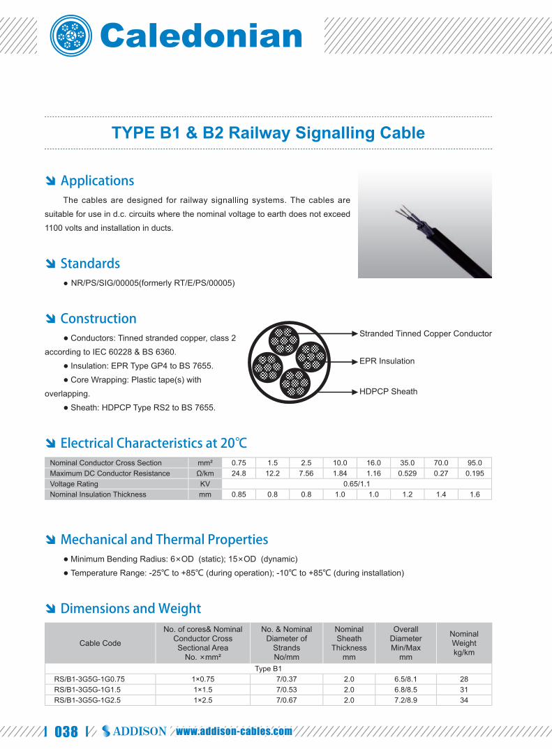
038 www.addison-cables.com
TYPE B1 & B2 Railway Signalling Cable
Applications The cables are designed for railway signalling systems. The cables are
suitable for use in d.c. circuits where the nominal voltage to earth does not exceed
1100 volts and installation in ducts.
Standards NR/PS/SIG/00005(formerly RT/E/PS/00005) ●
Construction ● Conductors: Tinned stranded copper, class 2
according to IEC 60228 & BS 6360.
● Insulation: EPR Type GP4 to BS 7655.
● Core Wrapping: Plastic tape(s) with
overlapping.
● Sheath: HDPCP Type RS2 to BS 7655.
Electrical Characteristics at 20℃ Nominal Conductor Cross Section mm² 0.75 1.5 2.5 10.0 16.0 35.0 70.0 95.0Maximum DC Conductor Resistance Ω/km 24.8 12.2 7.56 1.84 1.16 0.529 0.27 0.195Voltage Rating KV 0.65/1.1Nominal Insulation Thickness mm 0.85 0.8 0.8 1.0 1.0 1.2 1.4 1.6
Mechanical and Thermal Properties ● Minimum Bending Radius: 6×OD (static); 15×OD (dynamic)
● Temperature Range: -25℃ to +85℃ (during operation); -10℃ to +85℃ (during installation)
Dimensions and Weight
Cable Code
No. of cores& Nominal Conductor Cross Sectional Area
No. ×mm²
No. & Nominal Diameter of
StrandsNo/mm
Nominal Sheath
Thicknessmm
Overall DiameterMin/Max
mm
Nominal Weightkg/km
Type B1RS/B1-3G5G-1G0.75 1×0.75 7/0.37 2.0 6.5/8.1 28RS/B1-3G5G-1G1.5 1×1.5 7/0.53 2.0 6.8/8.5 31RS/B1-3G5G-1G2.5 1×2.5 7/0.67 2.0 7.2/8.9 34
EPR Insulation
Stranded Tinned Copper Conductor
HDPCP Sheath

039
Caledonian Railway Cableswww.caledonian-cables.co.uk
Cable Code
No. of cores& Nominal Conductor Cross Sectional Area
No. ×mm²
No. & Nominal Diameter of
StrandsNo/mm
Nominal Sheath
Thicknessmm
Overall DiameterMin/Max
mm
Nominal Weightkg/km
RS/B1-3G5G-1G10 1×10.0 7/1.35 2.0 9.4/11.8 205RS/B1-3G5G-1G35 1×35.0 19/1.53 2.0 12.9/16.1 495
Type B2RS/B2-3G5G-2G1.5 2×1.5 7/0.53 2.0 9.4/12.1 135RS/B2-3G5G-2G2.5 2×2.5 7/0.67 2.0 10.5/13.1 170RS/B2-3G5G-2G10 2×10.0 7/1.35 2.0 15.0/18.7 443RS/B2-3G5G-2G16 2×16.0 7/1.70 2.0 16.7/20.9 625RS/B2-3G5G-2G35 2×35.0 19/1.53 2.2 22.3/27.8 1232RS/B2-3G5G-2G70 2×70.0 19/2.14 2.4 28.8/36.0 2053RS/B2-3G5G-2G95 2×95.0 19/2.52 2.6 33.2/41.5 2968RS/B2-3G5G-4G0.75 4×0.75 7/0.37 2.0 10.2/12.8 140RS/B2-3G5G-7G0.75 7×0.75 7/0.37 2.0 11.8/14.7 214RS/B2-3G5G-10G0.75 10×0.75 7/0.37 2.0 14.4/18.0 280RS/B2-3G5G-12G0.75 12×0.75 7/0.37 2.0 14.8/18.5 321RS/B2-3G5G-19G0.75 19×0.75 7/0.37 2.0 17.0/21.3 451RS/B2-3G5G-27G0.75 27×0.75 7/0.37 2.0 20.1/25.1 602RS/B2-3G5G-37G0.75 37×0.75 7/0.37 2.2 22.7/28.4 799RS/B2-3G5G-48G0.75 48×0.75 7/0.37 2.2 25.7/32.2 973RS/B2-3G5G-4G1.5 4×1.5 7/0.53 2.0 10.9/13.7 217RS/B2-3G5G-7G1.5 7×1.5 7/0.53 2.0 12.6/15.8 296RS/B2-3G5G-10G1.5 10×1.5 7/0.53 2.0 15.6/19.4 401RS/B2-3G5G-12G1.5 12×1.5 7/0.53 2.0 16.0/20.0 437RS/B2-3G5G-19G1.5 19×1.5 7/0.53 2.0 18.5/23.1 615RS/B2-3G5G-27G1.5 27×1.5 7/0.53 2.2 22.2/27.8 856RS/B2-3G5G-37G1.5 37×1.5 7/0.53 2.2 25.1/31.4 1126RS/B2-3G5G-48G1.5 48×1.5 7/0.53 2.4 28.1/35.1 1494RS/B2-3G5G-4G2.5 4×2.5 7/0.67 2.0 11.9/14.8 260RS/B2-3G5G-7G2.5 7×2.5 7/0.67 2.0 13.8/17.2 370RS/B2-3G5G-10G2.5 10×2.5 7/0.67 2.0 17.1/21.3 520RS/B2-3G5G-12G2.5 12×2.5 7/0.67 2.0 17.6/22.0 599RS/B2-3G5G-19G2.5 19×2.5 7/0.67 2.0 20.4/25.5 835RS/B2-3G5G-27G2.5 27×2.5 7/0.67 2.2 24.6/30.7 1232RS/B2-3G5G-37G2.5 37×2.5 7/0.67 2.4 27.8/34.7 1623RS/B2-3G5G-48G2.5 48×2.5 7/0.67 2.6 31.2/39.0 2032RS/B2-3G5G-6P0.75S 6×2×0.75 7/0.37 2.0 19.7/24.6 372
Impact Resistant Highly Flexible Oil Resistant Weather Resistant Rated Voltage
650/1100V
Laid In Ducts
RAILSIG RAILWAY SIGNALLING & CONTROL CABLES
Multicore Signalling & Control Main Cables for Trackside UK NETWORK RAIL Standard

040 www.addison-cables.com
TYPE C1 & C2 Railway Signalling Cable
Applications The cables are designed for railway signalling systems. The cables are
suitable for use in d.c. circuits where the nominal voltage to earth does not exceed 1100 volts and installation in ducts.
Standard NR/PS/SIG/00005(formerly RT/E/PS/00005) ●
Construction Conductors: Tinned stranded copper, class 5 ●
according to IEC 60228 & BS 6360.
Insulation: EPR Type GP4 to BS 7655. ●
Core Wrapping: Plastic tape(s) with overlapping. ●
Sheath: HDPCP Type RS2 to BS 7655. ●
Electrical Characteristics at 20℃ Nominal Conductor Cross Section mm² 2.5Maximum DC Conductor Resistance Ω/km 8.21Voltage Rating KV 0.65/1.1Nominal Insulation Thickness mm 1.05
Mechanical and Thermal Properties Minimum Bending Radius: 6×OD (static); 15×OD (dynamic) ●
Temperature Range: -25℃ to +85℃ (during operation); ●
-10℃ to +85℃ (during installation)
Dimensions and Weight
Cable Code
No. of cores& Nominal Conductor Cross Sectional
AreaNo.×mm²
No. & Nominal Diameter of Strands
No/mm
Nominal Sheath
Thicknessmm
Overall DiameterMin/Max
mm
Nominal Weightkg/km
Type C1RS/C1-3G5G-1G2.5 1×2.5 50/0.25 3.8 11.2/14.0 195
Type C2RS/C2-3G5G-2G2.5 2×2.5 50/0.25 3.8 14.9/18.8 370RS/C2-3G5G-4G2.5 4×2.5 50/0.25 3.8 16.4/20.9 460RS/C2-3G5G-7G2.5 7×2.5 50/0.25 3.8 18.7/23.7 610RS/C2-3G5G-10G2.5 10×2.5 50/0.25 3.8 22.5/28.6 920RS/C2-3G5G-12G2.5 12×2.5 50/0.25 3.8 23.2/29.3 950RS/C2-3G5G-16G2.5 16×2.5 50/0.25 3.8 25.3/32.0 1180
Routine test voltage: 2.5kV for 5 minute
EPR Insulation
Stranded Tinned Copper Conductor
HDPCP Sheath
Impact Resistant Highly Flexible Oil Resistant
Weather Resistant Rated Voltage
650/1100V
Laid In Ducts

041
Caledonian Railway Cableswww.caledonian-cables.co.uk
TYPE C3 Railway Signalling Cable
Applications The cables are designed for railway signalling systems. The cables are
suitable for use in d.c. circuits where the nominal voltage to earth does not exceed
1100 volts and installation in ducts.
Standard NR/PS/SIG/00005(formerly RT/E/PS/00005) ●
Construction ● Conductors: Tinned stranded copper, class 5
according to IEC 60228 & BS 6360.
● Insulation: EPR Type GP4 to BS 7655.
● Screen: Aluminium tape.
● Drain Wire: 2.5 mm² fl exible tinned copper.
● Sheath: HDPCP Type RS2 to BS 7655.
Electrical Characteristics at 20℃ Nominal Conductor Cross Section mm² 2.5Maximum DC Conductor Resistance Ω/km 8.21Minimum Noise Reduction dB 60Voltage Rating KV 0.65/1.1Nominal Insulation Thickness mm 1.05
Mechanical and Thermal Properties Minimum Bending Radius: 6×OD (static); 15×OD (dynamic) ●
Temperature Range: -25℃ to +85℃ (during operation); ●
-10℃ to +85℃ (during installation)
Dimensions and Weight
Cable Code
No. of cores& Nominal Conductor Cross Sectional Area
No.×mm²
No. & Nominal Diameter of
StrandsNo/mm
Nominal Sheath
Thicknessmm
Overall DiameterMin/Max
mm
Nominal Weightkg/km
Type C3RS/C3-3G(St)5G-1P2.5S 1×2×2.5 50/0.25 3.8 15.0/20.0 390
Routine test voltage: 2.5kV for 5 minutes
EPR Insulation
Stranded Tinned Copper Conductor
Drain Wire
HDPCP Sheath
Aluminium Tape
Impact Resistant Highly Flexible Oil Resistant
Weather Resistant Rated Voltage
650/1100V
Laid In Ducts
RAILSIG RAILWAY SIGNALLING & CONTROL CABLES
Multicore Signalling & Control Main Cables for Trackside UK NETWORK RAIL Standard

042 www.addison-cables.com
TYPE D1 & D2 Railway Signalling Cable
Applications The cables are designed for railway signalling systems. The cables are
suitable for use in d.c. circuits where the nominal voltage to earth does not exceed
1100 volts and installation in ducts.
Standards NR/PS/SIG/00005(formerly RT/E/PS/00005) ●
Construction ● Conductors: Tinned stranded copper,
according to IEC 60228 class 2& BS 6360.
● Insulation: LSZH or EPR Type GP4 to BS 7655.
● Core Wrapping: Plastic tape(s) with overlapping.
● Sheath: LSZH.
Electrical Characteristics at 20℃ Nominal Conductor Cross Section mm² 0.75 1.5 2.5 10.0 16.0 35.0 70.0 95.0Maximum DC Conductor Resistance Ω/km 24.8 12.2 7.56 1.84 1.16 0.529 0.27 0.195Voltage Rating KV 0.65/1.1Nominal Insulation Thickness mm 0.85 0.8 0.8 1.0 1.0 1.2 1.4 1.6
Mechanical and Thermal Properties ● Minimum Bending Radius: 6×OD (static); 15×OD (dynamic)
● Temperature Range: -25℃ to +85℃ (during operation); -10℃ to +85℃ (during installation)
Dimensions and Weight
Cable Code
No. of cores& Nominal Conductor Cross Sectional Area
No.×mm²
No. & Nominal Diameter of Strands
No/mm
Nominal Sheath
Thicknessmm
Overall DiameterMin/Max
mm
Nominal Weightkg/km
Type D1RS/D1-3GH-1G0.75 1×0.75 7/0.37 2.0 6.5/8.1 25RS/D1-3GH-1G1.5 1×1.5 7/0.53 2.0 6.8/8.5 30RS/D1-3GH-1G2.5 1×2.5 7/0.67 2.0 7.2/8.9 34RS/D1-3GH-1G10 1×10.0 7/1.35 2.0 9.4/11.8 205RS/D1-3GH-1G35 1×35.0 19/1.53 2.0 12.9/16.1 495
LSZH/EPR Insulation
Stranded Tinned Copper Conductor
LSZH Sheath
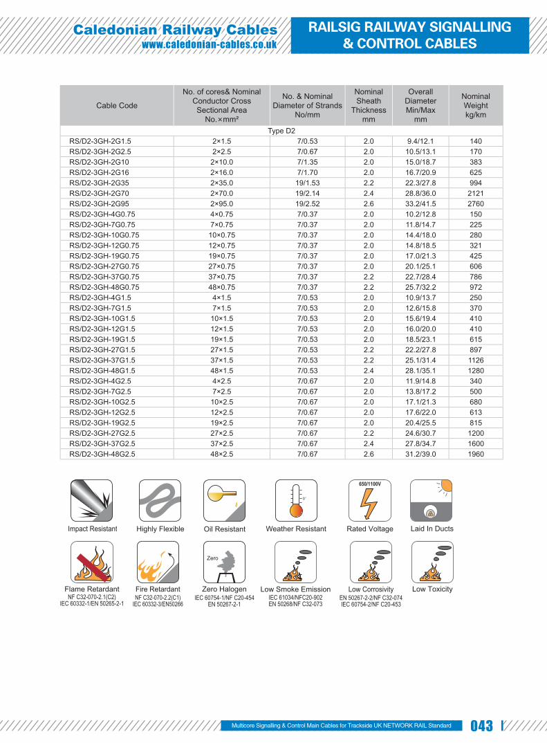
043
Caledonian Railway Cableswww.caledonian-cables.co.uk
Cable Code
No. of cores& Nominal Conductor Cross Sectional Area
No.×mm²
No. & Nominal Diameter of Strands
No/mm
Nominal Sheath
Thicknessmm
Overall DiameterMin/Max
mm
Nominal Weightkg/km
Type D2RS/D2-3GH-2G1.5 2×1.5 7/0.53 2.0 9.4/12.1 140RS/D2-3GH-2G2.5 2×2.5 7/0.67 2.0 10.5/13.1 170RS/D2-3GH-2G10 2×10.0 7/1.35 2.0 15.0/18.7 383RS/D2-3GH-2G16 2×16.0 7/1.70 2.0 16.7/20.9 625RS/D2-3GH-2G35 2×35.0 19/1.53 2.2 22.3/27.8 994RS/D2-3GH-2G70 2×70.0 19/2.14 2.4 28.8/36.0 2121RS/D2-3GH-2G95 2×95.0 19/2.52 2.6 33.2/41.5 2760RS/D2-3GH-4G0.75 4×0.75 7/0.37 2.0 10.2/12.8 150RS/D2-3GH-7G0.75 7×0.75 7/0.37 2.0 11.8/14.7 225RS/D2-3GH-10G0.75 10×0.75 7/0.37 2.0 14.4/18.0 280RS/D2-3GH-12G0.75 12×0.75 7/0.37 2.0 14.8/18.5 321RS/D2-3GH-19G0.75 19×0.75 7/0.37 2.0 17.0/21.3 425RS/D2-3GH-27G0.75 27×0.75 7/0.37 2.0 20.1/25.1 606RS/D2-3GH-37G0.75 37×0.75 7/0.37 2.2 22.7/28.4 786RS/D2-3GH-48G0.75 48×0.75 7/0.37 2.2 25.7/32.2 972RS/D2-3GH-4G1.5 4×1.5 7/0.53 2.0 10.9/13.7 250RS/D2-3GH-7G1.5 7×1.5 7/0.53 2.0 12.6/15.8 370RS/D2-3GH-10G1.5 10×1.5 7/0.53 2.0 15.6/19.4 410RS/D2-3GH-12G1.5 12×1.5 7/0.53 2.0 16.0/20.0 410RS/D2-3GH-19G1.5 19×1.5 7/0.53 2.0 18.5/23.1 615RS/D2-3GH-27G1.5 27×1.5 7/0.53 2.2 22.2/27.8 897RS/D2-3GH-37G1.5 37×1.5 7/0.53 2.2 25.1/31.4 1126RS/D2-3GH-48G1.5 48×1.5 7/0.53 2.4 28.1/35.1 1280RS/D2-3GH-4G2.5 4×2.5 7/0.67 2.0 11.9/14.8 340RS/D2-3GH-7G2.5 7×2.5 7/0.67 2.0 13.8/17.2 500RS/D2-3GH-10G2.5 10×2.5 7/0.67 2.0 17.1/21.3 680RS/D2-3GH-12G2.5 12×2.5 7/0.67 2.0 17.6/22.0 613RS/D2-3GH-19G2.5 19×2.5 7/0.67 2.0 20.4/25.5 815RS/D2-3GH-27G2.5 27×2.5 7/0.67 2.2 24.6/30.7 1200RS/D2-3GH-37G2.5 37×2.5 7/0.67 2.4 27.8/34.7 1600RS/D2-3GH-48G2.5 48×2.5 7/0.67 2.6 31.2/39.0 1960
Multicore Signalling & Control Main Cables for Trackside UK NETWORK RAIL Standard
Impact Resistant Highly Flexible Oil Resistant Weather Resistant Rated Voltage
650/1100V
Laid In Ducts
Flame RetardantNF C32-070-2.1(C2)
IEC 60332-1/EN 50265-2-1NF C32-070-2.2(C1)
IEC 60332-3/EN50266
Fire Retardant Zero HalogenIEC 60754-1/NF C20-454
EN 50267-2-1
Zero
Low Smoke EmissionIEC 61034/NFC20-902EN 50268/NF C32-073
EN 50267-2-2/NF C32-074IEC 60754-2/NF C20-453
Low Corrosivity Low Toxicity
RAILSIG RAILWAY SIGNALLING & CONTROL CABLES

044 www.addison-cables.com
TYPE E1 & E2 Railway Signalling Cable
Applications The cables are designed for railway signalling systems. The cables are
suitable for use in d.c. circuits where the nominal voltage to earth does not exceed
1100 volts and installation in ducts.
Standards NR/PS/SIG/00005(formerly RT/E/PS/00005) ●
Construction ● Conductors: Tinned stranded copper, class 5
according to IEC 60228 & BS 6360.
● Insulation: LSZH or EPR Type GP4 to BS 7655.
● Outer Sheath: LSZH.
Electrical Characteristics at 20 ℃ Nominal Conductor Cross Section mm² 2.5Maximum DC Conductor Resistance Ω/km 8.21Voltage Rating KV 0.65/1.1Nominal Insulation Thickness mm 1.05
Mechanical and Thermal Properties ● Minimum Bending Radius: 6×OD (static); 15×OD (dynamic)
● Temperature Range: -25℃ to +85℃ (during operation); -10℃ to +85℃ (during installation)
Dimensions and Weight
Cable Code
No. of cores& Nominal Conductor Cross Sectional
Area No.×mm²
No. & Nominal Diameter of
StrandsNo/mm
Nominal Sheath Thickness
mm
Overall DiameterMin/Max
mm
Nominal Weightkg/km
Type E1RS/E1-3GH-1G2.5 1×2.5 50/0.25 3.8 11.2/14.0 200
Type E2RS/E2-3GH-2G2.5 2×2.5 50/0.25 3.8 14.9/18.8 380RS/E2-3GH-4G2.5 4×2.5 50/0.25 3.8 16.4/20.9 470RS/E2-3GH-7G2.5 7×2.5 50/0.25 3.8 18.7/23.7 625RS/E2-3GH-10G2.5 10×2.5 50/0.25 3.8 22.5/28.6 940
LSZH/EPR Insulation
Stranded Tinned Copper Conductor
LSZH Sheath

045
Caledonian Railway Cableswww.caledonian-cables.co.uk
Multicore Signalling & Control Main Cables for Trackside UK NETWORK RAIL Standard
Cable Code
No. of cores& Nominal Conductor Cross Sectional
Area No.×mm²
No. & Nominal Diameter of
StrandsNo/mm
Nominal Sheath Thickness
mm
Overall DiameterMin/Max
mm
Nominal Weightkg/km
RS/E2-3GH-12G2.5 12×2.5 50/0.25 3.8 23.2/29.3 980RS/E2-3GH-16G2.5 16×2.5 50/0.25 3.8 25.3/32.0 1200RS/E2-3GH-1P2.5S 1×2×2.5 50/0.25 3.8 15.0/20.0 341
Routine test voltage: 2.5kV for 5 minutes
Impact Resistant Highly Flexible Oil Resistant Weather Resistant Rated Voltage
650/1100V
Laid In Ducts
Flame RetardantNF C32-070-2.1(C2)
IEC 60332-1/EN 50265-2-1NF C32-070-2.2(C1)
IEC 60332-3/EN50266
Fire Retardant Zero HalogenIEC 60754-1/NF C20-454
EN 50267-2-1
Zero
Low Smoke EmissionIEC 61034/NFC20-902EN 50268/NF C32-073
EN 50267-2-2/NF C32-074IEC 60754-2/NF C20-453
Low Corrosivity Low Toxicity
RAILSIG RAILWAY SIGNALLING & CONTROL CABLES

046 www.addison-cables.com
TYPE E3 Railway Signalling Cable
Applications The cables are designed for railway signalling systems. The cables are
suitable for use in d.c. circuits where the nominal voltage to earth does not exceed
1100 volts and installation in ducts.
Standards NR/PS/SIG/00005(formerly RT/E/PS/00005) ●
Construction Conductor: Tinned stranded copper, according ●
to IEC 60228 class 5& BS 6360.
Insulation: LSZH or EPR Type GP4 to BS ●
7655.
Screen: Aluminium tape. ●
Drain Wire: 2.5 mm² fl exible tinned copper. ●
Sheath: LSZH. ●
Electrical Characteristics at 20℃ Nominal Conductor Cross Section mm² 2.5Maximum DC Conductor Resistance Ω/km 8.21Minimum Noise Reduction dB 60Voltage Rating KV 0.65/1.1Nominal Insulation Thickness mm 1.05
Mechanical and Thermal Properties ● Minimum Bending Radius: 6×OD (static); 15×OD (dynamic)
● Temperature Range: -25℃ to +85℃ (during operation); -10℃ to +85℃ (during installation)
LSZH/EPR Insulation
Stranded Tinned Copper Conductor
Drain Wire
LSZH Sheath
Aluminium Tape

047
Caledonian Railway Cableswww.caledonian-cables.co.uk
Dimensions and Weight
Cable Code
No. of cores& Nominal Conductor Cross Sectional Area
No.×mm²
No. & Nominal Diameter of
StrandsNo/mm
Nominal Sheath
Thicknessmm
Overall DiameterMin/Max
mm
Nominal Weightkg/km
Type E3RS/E3-3G(St)H-1P2.5S 1 x 2 x 2.5 50/0.25 3.8 15.0/20.0 410
Routine test voltage: 2.5kV for 5 minutes
Impact Resistant Highly Flexible Oil Resistant Weather Resistant Rated Voltage
650/1100V
Laid In Ducts
Flame RetardantNF C32-070-2.1(C2)
IEC 60332-1/EN 50265-2-1NF C32-070-2.2(C1)
IEC 60332-3/EN50266
Fire Retardant Zero HalogenIEC 60754-1/NF C20-454
EN 50267-2-1
Zero
Low Smoke EmissionIEC 61034/NFC20-902EN 50268/NF C32-073
EN 50267-2-2/NF C32-074IEC 60754-2/NF C20-453
Low Corrosivity Low Toxicity
Multicore Signalling & Control Main Cables for Trackside UK NETWORK RAIL Standard
RAILSIG RAILWAY SIGNALLING & CONTROL CABLES

048 www.addison-cables.com
EAPSP n×1×1.4
Applications The cables are used as railway cables and can be installed directly into the
ground or in ducts.
Standards RENFE E.T. 03.365.051.6 ●
Construction Conductors: Soft annealed solid copper, 1.4 ●
mm nominal diameter.
Insulation: PE insulation. ●
Stranding: Cores are helically stranded in ●
concentric layers.
Core Wrapping: Plast ic tape(s) with ●
overlapping.
Moisture Barrier: One laminated sheath made of aluminium tape (0.2mm thick) coated with copolymer on at least ●
one side is applied longitudinally with overlap.
Inner Sheath: PE sheath. ●
Armour: One corrugated steel tape is longitudinally applied with overlap. ●
Outer Sheath: PE sheath. ●
Electrical Characteristics at 20℃ Nominal Conductor Diameter mm 1.4Maximum Conductor Resistance Ω/km 11.7Minimum Insulation Resistance @500 V DC MΩ.km 25000Resistance Unbalance % 2Test Voltage @50Hz 1min
Core to Core Veff 2100Core to Screen Veff 2500Core to Armouring Veff 2000
Mechanical and Thermal Properties Minimum Bending Radius: 10×OD ●
Temperature Range: -30℃ to +70℃ (during operation); -10℃ +50℃ (during installation) ●
Solid Copper ConductorSolid PE Insulation
Non Hygroscopic Tape
Inner PE Sheath
Outer PE Sheath
Corrugated Steel Tape
PE-copolymer Coated Aluminium Tape

049
Caledonian Railway Cableswww.caledonian-cables.co.uk
Dimensions and Weight
Cable Code Number of Cores
Nominal Sheath Thickness mm
Maximum Overall Diameter
mm
Nominal Weightkg/kmInner Outer
1.4mm Conductor, 2.6mm Insulated WireRS/EAPSP-2Y(L)2Y(SR)2Y-4C1.4 4 1.3 1.4 15.7 270RS/EAPSP-2Y(L)2Y(SR)2Y-7C1.4 7 1.3 1.4 17.1 350RS/EAPSP-2Y(L)2Y(SR)2Y-9C1.4 9 1.3 1.4 19.9 420RS/EAPSP-2Y(L)2Y(SR)2Y-12C1.4 12 1.3 1.4 20.0 480RS/EAPSP-2Y(L)2Y(SR)2Y-19C1.4 19 1.3 1.4 22.0 630RS/EAPSP-2Y(L)2Y(SR)2Y-27C1.4 27 1.3 1.4 24.8 810RS/EAPSP-2Y(L)2Y(SR)2Y-37C1.4 37 1.3 1.4 26.9 1010RS/EAPSP-2Y(L)2Y(SR)2Y-48C1.4 48 1.3 1.4 29.7 1240RS/EAPSP-2Y(L)2Y(SR)2Y-61C1.4 61 1.3 1.4 31.8 1490
Multicore Signalling & Control Main Cables for Trackside Spain RENFE Railway Standard
UV Resistant Water Resistant Rated Voltage
300/500V
Buried in Ciround Laid In Ducts Zero HalogenIEC 60754-1/NF C20-454
EN 50267-2-1
Zero
RAILSIG RAILWAY SIGNALLING & CONTROL CABLES

050 www.addison-cables.com
CCPSSP-FR0.3 n×1×1.4
Applications The cables are used as railway cables and can be installed directly into the
ground or in ducts.
Standards RENFE E.T. 03.365.051.6 ●
Construction Conductors: Soft annealed solid copper, 1.4 mm nominal ●
diameter.
Insulation: PE insulation. ●
Stranding: Cores are helically stranded in concentric ●
layers.
Core Wrapping: Two or more layers of plastic tape(s) with overlapping. ●
Screen: Copper tapes with overlap (protection against interference). ●
Inner Sheath: PE sheath. ●
Armour: Two layers of steel tape (0.8mm thick). ●
Outer Sheath: PE sheath. ●
Electrical Characteristics at 20℃ Nominal Conductor Diameter mm 1.4Maximum Conductor Resistance Ω/km 11.9Minimum Insulation Resistance @500 V DC MΩ.km 15000Resistance Unbalance % 2Test Voltage @50Hz 1min
Core to Core Veff 2100Core to Screen Veff 2500
Reduction Factor @100V/km 50Hz 0.3
Mechanical and Thermal Properties ● Minimum Bending Radius: 10×OD
● Temperature Range: -40℃ to +60℃ (during operation); -10℃ +60℃ (during installation)
Solid Copper ConductorSolid PE Insulation
Copper Tape ScreenNon Hygroscopic Tape
Inner PE Sheath
Outer PE Sheath
Double Steel Tapes

051
Caledonian Railway Cableswww.caledonian-cables.co.uk
Dimensions and Weight
Cable Code Number of Cores
Nominal Sheath Thickness mm
Maximum Overall Diameter
mm
Nominal Weightkg/kmInner Outer
1.4mm Conductor, 2.6mm Insulated WireRS/CCPSSP-FR0.3-2Y(K)2YB2Y-2C1.4 2 1.5 1.6 16.5 530RS/CCPSSP-FR0.3-2Y(K)2YB2Y-4C1.4 4 1.5 1.6 17.5 608RS/CCPSSP-FR0.3-2Y(K)2YB2Y-7C1.4 7 1.5 1.6 19.0 718RS/CCPSSP-FR0.3-2Y(K)2YB2Y-9C1.4 9 1.5 1.6 22.7 914RS/CCPSSP-FR0.3-2Y(K)2YB2Y-12C1.4 12 1.5 1.6 23.2 977RS/CCPSSP-FR0.3-2Y(K)2YB2Y-19C1.4 19 1.6 1.8 25.2 1185RS/CCPSSP-FR0.3-2Y(K)2YB2Y-27C1.4 27 1.6 1.8 28.1 1437RS/CCPSSP-FR0.3-2Y(K)2YB2Y-37C1.4 37 1.7 1.8 31.4 1754RS/CCPSSP-FR0.3-2Y(K)2YB2Y-48C1.4 48 1.7 1.8 34.2 2062
Multicore Signalling & Control Main Cables for Trackside Spain RENFE Railway Standard
UV Resistant Water Resistant Rated Voltage
300/500V
Buried in Ciround Laid In Ducts Zero HalogenIEC 60754-1/NF C20-454
EN 50267-2-1
Zero
Anti Induction
EMI
RAILSIG RAILWAY SIGNALLING & CONTROL CABLES

052 www.addison-cables.com
CCTSST-FR0.3 n×1×1.4
Applications The cables are used as railway cables and can be installed directly into the
ground or in ducts.
Standards RENFE E.T. 03.365.051.6 ●
Co nstructionConductors: Soft annealed solid copper, 1.4 mm nominal ●
diameter.
Insulation: PE insulation. ●
Stranding: Cores are helically stranded in concentric ●
layers.
Core Wrapping: Two or more layers of plastic tape(s) with overlapping. ●
Screen: Copper tapes with overlap (protection against interference). ●
Inner Sheath: FRNC-PE sheath, coloured green. ●
Armour: Two layers of steel tape (0.8mm thick). ●
Outer Sheath: FRNC-PE sheath, coloured green. ●
*FRNC: Flame retardant, non corrosive.
Electrical Characteristics at 20℃ Nominal Conductor Diameter mm 1.4Maximum Conductor Resistance Ω/km 11.7Minimum Insulation Resistance @500 V DC MΩ.km 35000Resistance Unbalance % 2Test Voltage @50Hz 1min
Core to Core Veff 2100Core to Screen Veff 2500
Reduction Factor @100V/km 50Hz 0.3
Mechanical and Thermal Properties Minimum Bending Radius: 10×OD ●
Temperature Range: -40℃ to +60℃ (during operation); -10℃ +60℃ (during installation) ●
Solid Copper ConductorSolid PE Insulation
Copper Tape ScreenNon Hygroscopic Tape
Inner FRNC-PE Sheath
Outer FRNC-PE Sheath
Double Steel Tapes

053
Caledonian Railway Cableswww.caledonian-cables.co.uk
Dimensions and Weight
Cable Code Number of Cores
Nominal Sheath Thickness mm
Maximum Overall Diameter
mm
Nominal Weightkg/kmInner Outer
1.4mm Conductor, 2.6mm Insulated WireRS/CCTSST-FR0.3-2Y(K)HBH-4C1.4 4 1.5 1.6 18.0 705RS/CCTSST-FR0.3-2Y(K)HBH-19C1.4 19 1.6 1.8 26.1 1362RS/CCTSST-FR0.3-2Y(K)HBH-27C1.4 27 1.6 1.8 29.2 1648RS/CCTSST-FR0.3-2Y(K)HBH-48C1.4 48 1.7 1.8 36.7 2348
Anti Induction
EMIUV Resistant Water Resistant Rated Voltage
300/500V
Buried in Ciround Laid In Ducts
Flame RetardantNF C32-070-2.1(C2)
IEC 60332-1/EN 50265-2-1NF C32-070-2.2(C1)
IEC 60332-3/EN50266
Fire Retardant Zero HalogenIEC 60754-1/NF C20-454
EN 50267-2-1
Zero
Low Smoke EmissionIEC 61034/NFC20-902EN 50268/NF C32-073
EN 50267-2-2/NF C32-074IEC 60754-2/NF C20-453
Low Corrosivity Low Toxicity
RAILSIG RAILWAY SIGNALLING & CONTROL CABLES
Multicore Signalling & Control Main Cables for Trackside Spain RENFE Railway Standard

054 www.addison-cables.com
AJ-2Y(L)2YDB2Y S(H45)
Applications The cables are designed for transmission of low frequent signals up to 90
KHz through symmetric circuits in railway networks, and are suitable for laying
directly into the ground or in ducts.
Standards Dlk 1.013.109y ●
Dlk 1.013.110y ●
Construction Conductors: Solid Annealed copper, 0.9 ●
or 1.4 mm nominal diameter.
Insulation: Solid polyethylene. ●
Cabl ing E lement : Four insu la ted ●
conductors are twisted together to form a quad.
Stranding: Quads are helically stranded ●
in concentric layers. Cables from 7 quads
on, have two extra conductors of 0.5mm with
perforated insulation (surveillance conductors).
Core Wrapping: Plastic tape(s) with overlapping. ●
Moisture Barrier: One laminated sheath made of aluminium tape (0.15mm) coated with PE-Copolymer on at least ●
one side is applied with longitudinally overlap.
Inner Sheath: Low density polyethylene. ●
Electrostatic Shield: One layer of helically applied copper wires (0.9, 1.2, 1.4 or 1.8mm). ●
Electromagnetic Shield: Two helically applied steel tapes (0.5 or 0.8mm thick, depending on required reduction ●
factor).
Outer Sheath: Low density polyethylene. ●
Type Codes AJ– outdoor cable with protection against inductive infl uences
2Y solid PE conductor insulation
(L)2Y inner laminated PE sheath
D copper wire concentric screen
B steel tape armor
2Y outer PE sheath
Solid PE Insulation
Non Hygroscopic TapeExtra Perforated Insulated Conductor
Solid Copper Conductor
PE-copolymer Coated Aluminium TapeQuad
Outer PE Sheath
Inner PE SheathDouble Steel Tapes
Copper Wire

055
Caledonian Railway Cableswww.caledonian-cables.co.uk
S signal cable
LG layer stranding
H(n) operating capacity
Ring marking of Quad The single core is identifi ed by black ring markings:
Side Circuit 1 a-wire without marking
b-wire 1 mark distance 17mm
Side Circuit 2 a-wire 2 marks distance 34mm
b-wire 2 marks distance 17mm
Electrical Characteristics at 20 ℃ Nominal Conductor Diameter mm 0.9 1.4Maximum Conductor Resistance Ω/km 56.6 23.4Minimum Insulation Resistance @500 V DC (1min) MΩ.km 10000 10000Maximum Conductor Capacitance @800Hz (AC) nF/km 45 45Maximum Capacitance Unbalance @800Hz
K1 (100% / 50% all values) pF/km 650/150 650/150K9-12 neighboured quads pF/km 500/150 500/150K9-12 over-neighboured quads pF/km 150 150ea1/2 pF/km 1300 1300
Miniumum Far-end Crosstalk Attenuation @90KHz100% / 80% all values dB/km 58/62 33/45
Maximum Attenuation @90KHz dB/km 3.3 2.6Dielectric Strength, conductor to conductor (DC voltage 1min) V 3535 3535Surveillance Conductors
Loop resistance, maximum Ω/km 190 190Insulation resistance
- dry cable core, minimum MΩ.km 1000 1000- wet cable core, maximum KΩ.km 30 30
Optional: Nominal Reduction Factor @ 100 V/km, 16 2/3 Hzrk 401 series 0.15 0.15rk 501 series 0.35 0.35rk 601 series 0.55 0.55
Operating Voltage AC/DC V 420/600 420/600Test Voltage 50 Hz 1 min
Core to Core Veff 2500 2500Core to Screen Veff 2500 2500
Mechanical and Thermal Properties Minimum Bending Radius: 10×OD ●
Temperature Range: -40℃ to +60℃ (during operation); -10℃ +60℃ (during installation) ●
34mm
17mm
17mm 17mm
17mm
2
5
a-core
b-coreside circuit 1
without ring
a-core
b-coreside circuit 2
RAILSIG RAILWAY SIGNALLING & CONTROL CABLES
Multipair/Multiquad Signalling & Control Cables for Trackside German DB Railway Standard

056 www.addison-cables.com
Dimensions and Weight
Cable Code Number of Quads
Nominal Sheath Thickness mm
Nominal Overall Diameter
mm
Nominal Weightkg/kmInner Outer
0.9mm Conductor, 1.8mm Insulated Wire rk 601 SeriesRS109y-2Y(L)2YDB2Y-3Q0.9-S(H45)-R6 3 1.3 1.2 21.0 650RS109y-2Y(L)2YDB2Y-5Q0.9-S(H45)-R6 5 1.3 1.2 23.0 800RS109y-2Y(L)2YDB2Y-10Q0.9-S(H45)-R6 10 1.3 1.2 28.0 1130RS109y-2Y(L)2YDB2Y-20Q0.9-S(H45)-R6 20 1.3 1.2 35.0 1670RS109y-2Y(L)2YDB2Y-30Q0.9-S(H45)-R6 30 1.3 1.2 40.0 2180RS109y-2Y(L)2YDB2Y-40Q0.9-S(H45)-R6 40 1.3 1.2 45.0 2650
0.9mm Conductor, 1.8mm Insulated Wire rk 401 SeriesRS109y-2Y(L)2YDB2Y-10Q0.9-S(H45)-R4 10 1.3 1.2 31.0 1880RS109y-2Y(L)2YDB2Y-20Q0.9-S(H45)-R4 20 1.3 1.2 38.0 2640RS109y-2Y(L)2YDB2Y-30Q0.9-S(H45)-R4 30 1.3 1.2 43.0 3310RS109y-2Y(L)2YDB2Y-40Q0.9-S(H45)-R4 40 1.3 1.2 48.0 3880
1.4mm Conductor, 2.6mm Insulated Wire rk 501 SeriesRS109y-2Y(L)2YDB2Y-3Q1.4-S(H45)-R5 3 1.3 1.2 25.0 1060RS109y-2Y(L)2YDB2Y-5Q1.4-S(H45)-R5 5 1.3 1.2 29.0 1360RS109y-2Y(L)2YDB2Y-10Q1.4-S(H45)-R5 10 1.3 1.2 37.0 2040RS109y-2Y(L)2YDB2Y-20Q1.4-S(H45)-R5 20 1.3 1.2 47.0 3180RS109y-2Y(L)2YDB2Y-30Q1.4-S(H45)-R5 30 1.3 1.2 54.0 4220RS109y-2Y(L)2YDB2Y-40Q1.4-S(H45)-R5 40 1.3 1.2 61.0 5180
1.4mm Conductor, 2.6mm Insulated Wire rk 401 SeriesRS109y-2Y(L)2YDB2Y-3Q1.4-S(H45)-R4 3 1.3 1.2 28.0 1650RS109y-2Y(L)2YDB2Y-5Q1.4-S(H45)-R4 5 1.3 1.2 31.0 1950RS109y-2Y(L)2YDB2Y-10Q1.4-S(H45)-R4 10 1.3 1.2 39.0 2880RS109y-2Y(L)2YDB2Y-20Q1.4-S(H45)-R4 20 1.3 1.2 49.0 4180RS109y-2Y(L)2YDB2Y-30Q1.4-S(H45)-R4 30 1.3 1.2 56.0 5330RS109y-2Y(L)2YDB2Y-40Q1.4-S(H45)-R4 40 1.3 1.2 63.0 6430
Anti Induction
EMIUV Resistant Water Resistant Rated Voltage
600V DC/420V AC
Laid In Ducts Buried in Ciround Zero HalogenIEC 60754-1/NF C20-454
EN 50267-2-1
Zero

057
Caledonian Railway Cableswww.caledonian-cables.co.uk
A-2Y(L)2YB2Y S(H45)
Applications The cables are designed for transmission of low frequent signals up to 90
KHz through symmetric circuits in railway networks, and are suitable for laying directly into the ground or in ducts.
Standard sDlk 1.013.109y ●
Dlk 1.013.110y ●
Construction Conductor: Solid annealed copper, 0.9 or ●
1.4 mm nominal diameter.
Insulation: Solid polyethylene. ●
Cab l i ng E lemen t : Fou r i nsu la ted ●
conductors are twisted together to form a quad.
Stranding: Quads are helically stranded in concentric layers. Cables from 7 quads on, have two extra conductors ●
of 0.5mm with perforated insulation (surveillance conductors).
Core Wrapping: Plastic tape(s) with overlapping. ●
Moisture Barrier: One laminated sheath made of aluminium tape (0.15mm) coated with PE-Copolymer on at least ●
one side is applied with longitudinally overlap.
Inner Sheath: Low density polyethylene. ●
Electromagnetic Shield: One helically applied steel tape (0.2-0.3mm) or two helically applied steel tapes (0.1mm). ●
Outer Sheath: Low density polyethylene. ●
Type Codes A– outdoor cable 2Y solid PE conductor insulation(L)2Y PE inner laminated sheath B steel tape armor2Y PE outer sheath S signal cableLG layer stranding H(n) operating capacity
Ring marking of Quad The single core is identifi ed by black ring markings: Side Circuit 1 a-wire without marking b-wire 1 mark distance 17mmSide Circuit 2 a-wire 2 marks distance 34mm b-wire 2 marks distance 17mm
Solid PE Insulation
Non Hygroscopic Tape
Extra Perforated Insulated Conductor
Solid Copper Conductor
PE-copolymer Coated Aluminium TapeQuad
Outer PE SheathInner PE Sheath
One/Double Steel Tapes
Multipair/Multiquad Signalling & Control Cables for Trackside German DB Railway Standard
34mm
17mm
17mm 17mm
17mm
2
5
a-core
b-coreside circuit 1
without ring
a-core
b-coreside circuit 2
RAILSIG RAILWAY SIGNALLING & CONTROL CABLES

058 www.addison-cables.com
Electrical Characteristics at 20 ℃ Nominal Conductor Diameter mm 0.9 1.4Maximum Conductor Resistance Ω/km 56.6 23.4Minimum Insulation Resistance @500 V DC (1min) MΩ.km 10000 10000Maximum Conductor Capacitance @800Hz (AC) nF/km 45 45Maximum Capacitance unbalance @800Hz
K1 (100% / 50% all values) pF/km 650/150 650/150K9-12 neighboured quads pF/km 500/150 500/150K9-12 over-neighboured quads pF/km 150 150ea1/2 pF/km 1300 1300
Minimum Far-end Crosstalk Attenuation @90KHz100% / 80% all values dB/km 58/62 33/45
Maximum Attenuation @90KHz dB/km 3.3 2.6Dielectric Strength, conductor to conductor (DC voltage 1min) V 3535 3535Surveillance Conductors
Loop resistance, maximum Ω/km 190 190Insulation resistance
- dry cable core, minimum MΩ.km 1000 1000- wet cable core, maximum KΩ.km 30 30
Operating Voltage AC/DC V 420/600 420/600Test Voltage @50 Hz 1 min
Core to Core Veff 2500 2500Core to Screen Veff 2500 2500
Mechanical and Thermal Properties Minimum Bending Radius: 10×OD ●
Temperature Range: -40℃ to +60℃ (during operation); -10℃ +60℃ (during installation) ●
Dimensions and Weight
Cable Code Number of Quads
Nominal Sheath Thickness mm
Nominal Overall Diameter
mm
Nominal Weightkg/km
Inner Outer0.9mm Conductor, 1.8mm Insulated Wire
RS109y-2Y(L)2YB2Y-1Q0.9-S(H45) 1 1.3 1.2 12.0 170RS109y-2Y(L)2YB2Y-3Q0.9-S(H45) 3 1.3 1.2 17.0 310RS109y-2Y(L)2YB2Y-5Q0.9-S(H45) 5 1.3 1.2 19.0 410RS109y-2Y(L)2YB2Y-7Q0.9-S(H45) 7 1.3 1.2 21.0 500RS109y-2Y(L)2YB2Y-10Q0.9-S(H45) 10 1.3 1.2 24.0 640RS109y-2Y(L)2YB2Y-14Q0.9-S(H45) 14 1.3 1.2 27.0 800
1.4mm Conductor, 2.8mm Insulated WireRS109y-2Y(L)2YB2Y-1Q1.4-S(H45) 1 1.3 1.2 14.0 240RS109y-2Y(L)2YB2Y-3Q1.4-S(H45) 3 1.3 1.2 21.0 490RS109y-2Y(L)2YB2Y-5Q1.4-S(H45) 5 1.3 1.2 24.0 710RS109y-2Y(L)2YB2Y-7Q1.4-S(H45) 7 1.3 1.2 26.0 880RS109y-2Y(L)2YB2Y-10Q1.4-S(H45) 10 1.3 1.2 33.0 1190RS109y-2Y(L)2YB2Y-14Q1.4-S(H45) 14 1.3 1.2 36.5 1550
UV Resistant Water Resistant Rated Voltage
600V DC/420V AC
Laid In Ducts Buried in Ciround Zero HalogenIEC 60754-1/NF C20-454
EN 50267-2-1
Zero

059
Caledonian Railway Cableswww.caledonian-cables.co.uk
A-2Y(L)2Yv S(H45)
Applications The cables are designed for transmission of low frequent signals up to 90 KHz
through symmetric circuits in railway networks, and are suitable for laying directly into the ground or in ducts.
Standards Dlk 1.013.109y ●
Dlk 1.013.110y ●
Construction Conductors: Solid annealed copper, 0.9 or ●
1.4 mm nominal diameter.
Insulation: Solid polyethylene. ●
Cabling Element: Four insulated conductors ●
are twisted together to form a quad.
Stranding: Quads are helically stranded in ●
concentric layers. Cables from 7 quads on, have two extra conductors of 0.5mm with perforated insulation (surveillance
conductors).
Core Wrapping: Plastic tape(s) with overlapping. ●
Moisture Barrier: One laminated sheath made of aluminium tape (0.15mm) coated with PE-Copolymer on at least ●
one side is applied with longitudinally overlap.
Outer Sheath: Polyethylene, with reinforced radial thickness. ●
Type Codes A– outdoor cable 2Y solid PE conductor insulation(L)2Yv laminated sheath with increased wall thickness S signal cableLG layer stranding H(n) operating capacity
Ring marking of Quad The single core is identifi ed by black ring markings: Side Circuit 1 a-wire without marking b-wire 1 mark distance 17mmSide Circuit 2 a-wire 2 marks distance 34mm b-wire 2 marks distance 17mm
Solid PE Insulation
Non Hygroscopic Tape
Extra Perforated Insulated Conductor
Solid Copper Conductor
PE-copolymer Coated Aluminium TapeQuad
Reinforced PE Sheath
Multipair/Multiquad Signalling & Control Cables for Trackside German DB Railway Standard
34mm
17mm
17mm 17mm
17mm
2
5
a-core
b-coreside circuit 1
without ring
a-core
b-coreside circuit 2
RAILSIG RAILWAY SIGNALLING & CONTROL CABLES

060 www.addison-cables.com
Electrical Characteristics at 20℃ Nominal Conductor Diameter mm 0.9 1.4Maximum Conductor Resistance Ω/km 56.6 23.4Minimum Insulation Resistance @500 V DC (1min) MΩ.km 10000 10000Maximum Conductor Capacitance @800Hz (AC) nF/km 45 45Maximum Capacitance Unbalance @800Hz
K1 (100% / 50% all values) pF/km 650/150 650/150K9-12 neighboured quads pF/km 500/150 500/150K9-12 over-neighboured quads pF/km 150 150ea1/2 pF/km 1300 1300
Minimum Far-end Crosstalk Attenuation @90KHz100% / 80% all values dB/km 58/62 33/45
Maximum Attenuation @90KHz dB/km 3.3 2.6Dielectric Strength, conductor to conductor (DC voltage 1min) V 3535 3535Surveillance Conductors
Loop resistance, maximum Ω/km 190 190Insulation resistance
- dry cable core, minimum MΩ.km 1000 1000- wet cable core, maximum KΩ.km 30 30
Operating Voltage AC/DC V 420/600 420/600Test Voltage @50 Hz 1 min
Core to Core Veff 2500 2500Core to Screen Veff 2500 2500
Mechanical and Thermal Properties Minimum Bending Radius: 7.5×OD ●
Temperature Range: -40℃ to +60℃ (during operation); -10℃ +60℃ (during installation) ●
Dimensions and Weight
Cable Code Number of Quads
Nominal Sheath Thicknessmm
Nominal Overall Diametermm
Nominal Weightkg/km
0.9mm Conductor, 1.8mm Insulated WireRS109y-2Y(L)2Yv-1Q0.9-S(H45) 1 2.0 10.0 95RS109y-2Y(L)2Yv-3Q0.9-S(H45) 3 2.0 15.0 200RS109y-2Y(L)2Yv-5Q0.9-S(H45) 5 2.0 17.0 280RS109y-2Y(L)2Yv-7Q0.9-S(H45) 7 2.0 19.0 360RS109y-2Y(L)2Yv-10Q0.9-S(H45) 10 2.0 22.0 480RS109y-2Y(L)2Yv-14Q0.9-S(H45) 14 2.0 25.0 620RS109y-2Y(L)2Yv-20Q0.9-S(H45) 20 2.0 28.0 830RS109y-2Y(L)2Yv-30Q0.9-S(H45) 30 2.2 34.0 1200RS109y-2Y(L)2Yv-40Q0.9-S(H45) 40 2.2 38.0 1550
1.4mm Conductor, 2.8mm Insulated WireRS109y-2Y(L)2Yv-1Q1.4-S(H45) 1 2.0 12.0 150RS109y-2Y(L)2Yv-3Q1.4-S(H45) 3 2.0 19.0 350RS109y-2Y(L)2Yv-5Q1.4-S(H45) 5 2.0 22.0 530RS109y-2Y(L)2Yv-7Q1.4-S(H45) 7 2.0 24.0 690RS109y-2Y(L)2Yv-10Q1.4-S(H45) 10 2.0 29.0 950RS109y-2Y(L)2Yv-14Q1.4-S(H45) 14 2.2 33.0 1280RS109y-2Y(L)2Yv-20Q1.4-S(H45) 20 2.2 39.0 1750RS109y-2Y(L)2Yv-30Q1.4-S(H45) 30 2.2 46.0 2550RS109y-2Y(L)2Yv-40Q1.4-S(H45) 40 2.2 53.0 3320
UV Resistant Water Resistant Rated Voltage
600V DC/420V AC
Laid In Ducts Buried in Ciround Zero HalogenIEC 60754-1/NF C20-454
EN 50267-2-1
Zero
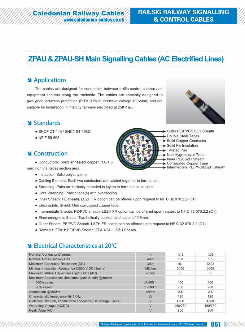
061
Caledonian Railway Cableswww.caledonian-cables.co.uk
ZPAU & ZPAU-SH Main Signalling Cables (AC Electrifi ed Lines)
Applications The cables are designed for connection between traffi c control centers and
equipment shelters along the trackside. The cables are specially designed to
give good induction protection (R.F= 0.26 at inductive voltage 100V/km) and are
suitable for installation in intercity railways electrifi ed at 25KV ac.
Standards SNCF CT 445 / SNCT ST 698G ●
NF F 55-698 ●
Construction Conductors: Solid annealed copper, 1.0/1.5 ●
mm² nominal cross section area.
Insulation: Solid polyethylene. ●
Cabling Element: Each two conductors are twisted together to form a pair. ●
Stranding: Pairs are helically stranded in layers to form the cable core. ●
Core Wrapping: Plastic tape(s) with overlapping. ●
Inner Sheath: PE sheath. LSZH FR option can be offered upon request to NF C 32 070.2.2 (C1). ●
Electrostatic Shield: One corrugated copper tape. ●
Intermediate Sheath: PE/PVC sheath. LSZH FR option can be offered upon request to NF C 32 070.2.2 (C1). ●
Electromagnetic Shield: Two helically applied steel tapes of 0.5mm. ●
Outer Sheath: PE/PVC Sheath. LSZH FR option can be offered upon request to NF C 32 070.2.2 (C1). ●
Remarks: ZPAU: PE/PVC Sheath; ZPAU-SH: LSZH Sheath. ●
Electrical Characteristics at 20℃ Nominal Conductor Diameter mm 1.13 1.38Nominal Cross Section Area mm² 1.0 1.5Maximum Conductor Resistance (DC) Ω/km 18.1 12.31Minimum Insulation Resistance @500 V DC (3mins) MΩ.km 5000 5000Maximum Mutual Capacitance @1000Hz (AC) nF/km 55 55Maximum Capacitance Unbalance (pair to pair) @800Hz
100% cases pF/500 m 400 40090% cases pF/500 m 200 200
Attenuation @45KHz dB/km 2.5 2.5Characteristic Impedance @45KHz Ω 120 120Dielectric Strength, conductor to conductor (DC voltage 3secs) V 4500 4500Operating Voltage (AC/DC) V 450/750 450/750Peak Value (AC) V 900 900
Solid Copper ConductorSolid PE InsulationTwisted PairNon Hygroscopic TapeInner PE/LSZH SheathCorrugated Copper TapeIntermediate PE/PVC/LSZH Sheath
Outer PE/PVC/LSZH SheathDouble Steel Tapes
Multipair/Multiquad Signalling & Control Cables for Trackside France RATP Railway Standard
RAILSIG RAILWAY SIGNALLING & CONTROL CABLES

062 www.addison-cables.com
Mechanical and Thermal Properties Minimum Bending Radius: 8×OD (static); 16×OD (dynamic) ●
Temperature Range: -40℃ to +70℃ (during operation); -20℃ to +50℃ (during installation) ●
Reduction Factor Inductive Voltage (V/km) Em 28 32 37 42 47 50 70 80 100 120 170 225Reduction Factor @50Hz Rk 0.75 0.70 0.60 0.50 0.40 0.35 0.30 0.28 0.26 0.25 0.24 0.25
Dimensions and Weight
Cable Code No. of PairsNominal Sheath Thickness
mmNominal Overall
Diametermm
Nominal Weightkg/kmInner Interm. Outer
1.13mm Conductor, 2.3mm Insulated WireRS/ZPAU-2Y2Y(K)2YB2Y-1P1S 1 1.0 0.8 1.6 16.2 490RS/ZPAU-2Y2Y(K)2YB2Y-2P1S 2 1.0 0.8 1.6 17.0 550RS/ZPAU-2Y2Y(K)2YB2Y-3P1S 3 1.0 0.8 1.6 22.2 820RS/ZPAU-2Y2Y(K)2YB2Y-4P1S 4 1.0 0.8 1.6 23.8 890RS/ZPAU-2Y2Y(K)2YB2Y-7P1S 7 1.0 0.8 1.7 26.7 1080RS/ZPAU-2Y2Y(K)2YB2Y-14P1S 14 1.2 0.8 1.8 32.3 1560RS/ZPAU-2Y2Y(K)2YB2Y-21P1S 21 1.2 1.1 2.0 37.2 1990RS/ZPAU-2Y2Y(K)2YB2Y-28P1S 28 1.2 1.1 2.2 41.4 2380RS/ZPAU-2Y2Y(K)2YB2Y-56P1S 56 1.3 1.3 2.5 52.9 3700
1.38mm Conductor, 2.55mm Insulated WireRS/ZPAU-2Y2Y(K)2YB2Y-14P1.5S 14 1.2 0.8 1.8 35.0 2050RS/ZPAU-2Y2Y(K)2YB2Y-21P1.5S 21 1.2 1.1 2.0 39.5 2525
PE Sheath
LSZH Sheath
Anti Induction
EMIUV Resistant Mineral Oil
ResistantRated voltage
750V DC/450V AC
Buried in Ciround Laid In Ducts
Zero HalogenIEC 60754-1/NF C20-454
EN 50267-2-1
Zero
Flame RetardantNF C32-070-2.1(C2)
IEC 60332-1/EN 50265-2-1NF C32-070-2.2(C1)
IEC 60332-3/EN50266
Fire Retardant Zero HalogenIEC 60754-1/NF C20-454
EN 50267-2-1
Zero
Low Smoke EmissionIEC 61034/NFC20-902EN 50268/NF C32-073
EN 50267-2-2/NF C32-074IEC 60754-2/NF C20-453
Low Corrosivity Low Toxicity
PVC Sheath
Flame RetardantNF C32-070-2.1(C2)
IEC 60332-1/EN 50265-2-1

063
Caledonian Railway Cableswww.caledonian-cables.co.uk
ZPFU & ZPFU-SH Main & Local Signalling Cables (DC Electrifi ed Lines)
Applications The cables are designed for the main signalling circuits of 1500V DC
electrifi ed lines.
Standards SNCF CT 445 ●
NF F 55-698 ●
Construction Conductors: Solid annealed copper, 1.0mm² nominal ●
cross section area.
Insulation: Solid polyethylene. ●
Cabling Element: Two conductors are twisted to form a pair. ●
Stranding: Pairs are helically stranded to form the cable core. ●
Core Wrapping: Plastic tape(s) with overlapping. ●
Inner Sheath: PE. LSZH FR option can be offered upon request to NF C 32 070.2.2 (C1). ●
Mechanical Protection: Two helically applied steel tapes (0.15, 0.2/0.5mm, depending on pair count). ●
Outer Sheath: PE/PVC. LSZH FR option can be offered upon request to NF C 32 070.2.2 (C1). ●
Remark: ZPFU: PE/PVC Sheath; ZPFU-SH: LSZH Sheath. ●
Electrical Characteristics at 20℃ Nominal Conductor Diameter mm 1.13Nominal Cross Section Area mm² 1Maximum Conductor Resistance (DC) Ω/km 18.1Minimum Insulation Resistance @500 V DC (3mins) MΩ.km 5000Maximum Mutual Capacitance (AC) @1000Hz nF/km 55Maximum Capacitance Unbalance @1000Hz pF/500 m 400Attenuation @45KHz dB/km 2.5Characteristic Impedance @45KHz Ω 120Dielectric Strength, conductor to conductor (DC voltage 3mins) V 4500Operating Voltage AC/DC V 450/750
Mechanical and Thermal Properties Minimum Bending Radius: 8×OD (static); 16×OD (dynamic) ●
Temperature Range: -40℃ to +70℃ (during operation); -20℃ to +50℃ (during installation) ●
Solid Copper ConductorSolid PE InsulationTwisted PairNon Hygroscopic TapeInner PE/LSZH Sheath
Outer PE/PVC/LSZH Sheath
Double Steel Tapes
Multipair/Multiquad Signalling & Control Cables for Trackside France RATP Railway Standard
RAILSIG RAILWAY SIGNALLING & CONTROL CABLES

064 www.addison-cables.com
Dimensions and Weight
Cable Code No. of Pairs
Nominal Sheath Thicknessmm
Nominal Overall Diameter
mm
Nominal Weightkg/km
Armour Thickness
mmInner Outer1.13mm Conductor, 2.3 Insulated Wire
RS/ZPFU-2Y2YB2Y-1P1S 1 1.0 1.5 11.7 207 0.15RS/ZPFU-2Y2YB2Y-2P1S 2 1.0 1.5 12.9 257 0.2RS/ZPFU-2Y2YB2Y-4P1S 4 1.0 1.6 16.8 509 0.2RS/ZPFU-2Y2YB2Y-7P1S 7 1.0 1.7 19.0 653 0.5RS/ZPFU-2Y2YB2Y-14P1S 14 1.2 1.8 24.1 1011 0.5RS/ZPFU-2Y2YB2Y-21P1S 21 1.2 2.0 27.8 1304 0.5RS/ZPFU-2Y2YB2Y-28P1S 28 1.2 2.2 31.0 1594 0.5RS/ZPFU-2Y2YB2Y-56P1S 56 1.3 2.5 40.5 2630 0.5
UV Resistant Mineral Oil Resistant
Rated voltage
750V DC/450V AC
Buried in Ciround Laid In Ducts
PE Sheath
LSZH Sheath
Zero HalogenIEC 60754-1/NF C20-454
EN 50267-2-1
Zero
Flame RetardantNF C32-070-2.1(C2)
IEC 60332-1/EN 50265-2-1NF C32-070-2.2(C1)
IEC 60332-3/EN50266
Fire Retardant Zero HalogenIEC 60754-1/NF C20-454
EN 50267-2-1
Zero
Low Smoke EmissionIEC 61034/NFC20-902EN 50268/NF C32-073
EN 50267-2-2/NF C32-074IEC 60754-2/NF C20-453
Low Corrosivity Low Toxicity
PVC Sheath
Flame RetardantNF C32-070-2.1(C2)
IEC 60332-1/EN 50265-2-1

065
Caledonian Railway Cableswww.caledonian-cables.co.uk
ZPGU Local Signalling Cables (DC Electrifi ed Lines)
Applications The cables are designed for internal connection inside cabling of equipment
shelters along the trackside. The shielded cables are suitable for local circuits.
Standards SNCF CT 445 ●
NF F 55-698 ●
Construction Conductors: Class 1 solid copper, 1.0 mm² nominal ●
cross section area.
Insulation: Solid polyethylene. ●
Cabling Element: Each two conductors are twisted ●
together to form a pair.
Inner Sheath: PE. ●
Screen: Aluminium/Polyethylene tape screen. ●
Drain Wire: Tinned copper drain wire. ●
Outer Sheath: PVC/LSZH. ●
Electrical Characteristics at 20℃ Nominal Conductor Diameter mm 1.13Nominal Cross Section Area mm² 1.0Maximum Conductor Resistance (DC) Ω/km 18.1Maximum Mutual Capacitance @1000Hz (AC) nF/km 55Operating Voltage V 750
Mechanical and Thermal Properties Minimum Bending Radius: 8×OD (static); 16×OD (dynamic) ●
Temperature Range: -40℃ to +70℃ (during operation); -20℃ to +50℃ (during installation) ●
Solid Copper ConductorSolid PE Insulation
Alu/Polyester Tape ScreenTinned Copper Drain WireInner PE Sheath
Outer PVC/LSZH Sheath
Twisted Pair
Multipair/Multiquad Signalling & Control Cables for Trackside France RATP Railway Standard
RAILSIG RAILWAY SIGNALLING & CONTROL CABLES

066 www.addison-cables.com
Dimensions and Weight
Cable Code No. of Pairs
Nominal Sheath Thicknessmm
Nominal Overall Diameter
mm
Nominal Weightkg/km
Inner Outer1.13mm Conductor, 2.3 Insulated Wire
RS/ZPGU-2Y2Y(L)Y-1P1S 1 1.0 1.5 9.8 95RS/ZPGU-2Y2Y(L)Y-2P1S 2 1.0 1.5 10.6 130RS/ZPGU-2Y2Y(L)Y-3P1S 3 1.0 1.5 13.2 179RS/ZPGU-2Y2Y(L)Y-7P1S 7 1.0 1.7 18.3 301RS/ZPGU-2Y2Y(L)Y-14P1S 14 1.2 1.8 21.3 532
Flame RetardantNF C32-070-2.1(C2)
IEC 60332-1/EN 50265-2-1NF C32-070-2.2(C1)
IEC 60332-3/EN50266
Fire Retardant Zero HalogenIEC 60754-1/NF C20-454
EN 50267-2-1
Zero
Low Smoke EmissionIEC 61034/NFC20-902EN 50268/NF C32-073
EN 50267-2-2/NF C32-074IEC 60754-2/NF C20-453
Low Corrosivity Low Toxicity
UV Resistant Mineral Oil Resistant
Rated voltage
750V DC/450V AC
Buried in Ciround Laid In Ducts
Flame RetardantNF C32-070-2.1(C2)
IEC 60332-1/EN 50265-2-1
PVC Sheath
LSZH Sheath

067
Caledonian Railway Cableswww.caledonian-cables.co.uk
ZCO3 & ZCO3-SH Main Signalling Cables (AC Electrifi ed High Speed Lines)
Applications The cables are designed for connection between traffi c control centers and
equipment shelters along the trackside. The cables are specially designed to give
good induction protection (R.F=0.21 at inductive voltage 100V/km) and are suitable
for installation in high speed railway lines electrifi ed at 25KV ac.
Standards SNCF CT 445 ●
NF F 55-698 ●
Construction Conductors: Solid annealed copper, 1.0 mm² ●
nominal cross section area.
Insulation: Solid polyethylene. ●
Cabling Element: Four conductors are twisted to form a quad. ●
Stranding: Quads are helically stranded to get the cable core. ●
Core Wrapping: Plastic tape(s) with overlapping. ●
Inner Sheath: Low density polyethylene. LSZH FR option can be offered upon request to NF C 32 070.2.2 (C1). ●
Electrostatic Shield: Corrugated copper tape. ●
Intermediate Sheath: Low density polyethylene. LSZH FR option can be offered upon request to NF C 32 070.2.2 ●
(C1).
Electromagnetic Shield: Two helically applied steel tapes (0.5mm). ●
Outer Sheath: PE/PVC compound. LSZH FR option can be offered upon request to NF C 32 070.2.2 (C1). ●
Remarks: ZCO3: PE/PVC Sheath; ZCO3-SH: LSZH Sheath. ●
Electrical Characteristics at 20℃ Nominal Conductor Diameter mm 1.13Nominal Cross Section Area mm² 1.0Maximum Conductor Resistance (DC) Ω/km 18.1Minimum Insulation Resistance @500 V DC (3mins) MΩ.km 5000Maximum Mutual Capacitance (AC) @1000Hz nF/km 40Maximum Capacitance Unbalance @800Hz pF/500m 400Dielectric Strength, conductor to conductor (DC voltage 3mins) V 4500Operating Voltage AC/DC V 450/750
Solid Copper ConductorSolid PE InsulationQuadNon Hygroscopic TapeInner PE/LSZH SheathCorrugated Copper TapeIntermediate PE/LSZH Sheath
Outer PE/PVC/LSZH SheathDouble Steel Tapes
Multipair/Multiquad Signalling & Control Cables for Trackside France RATP Railway Standard
RAILSIG RAILWAY SIGNALLING & CONTROL CABLES

068 www.addison-cables.com
Reduction Factor Inductive voltage(V/km) 50 70 100 370 400 470Reduction factor @50Hz 0.42 0.30 0.21 0.16 0.18 0.31
Mechanical and Thermal Properties Minimum Bending Radius: 8×OD (static); 16×OD (dynamic) ●
Temperature Range: -40℃ to +70℃ (during operation); -20℃ to +50℃ (during installation) ●
Dimensions and Weight
Cable Code No. of QuadsNominal Sheath Thickness
mmNominal Overall
Diametermm
Nominal Weightkg/km
Inner Interm. Outer1.13mm Conductor, 2.33 Insulated Wire
RS/ZCO3-2Y2Y(K)2YB2Y-2Q1S 2 0.8 1.0 1.6 27.0 1295RS/ZCO3-2Y2Y(K)2YB2Y-4Q1S 4 0.8 1.0 1.6 29.5 1490
Anti Induction
EMIUV Resistant Mineral Oil
ResistantRated voltage
750V DC/450V AC
Buried in Ciround Laid In Ducts
PE Sheath
LSZH Sheath
Zero HalogenIEC 60754-1/NF C20-454
EN 50267-2-1
Zero
Flame RetardantNF C32-070-2.1(C2)
IEC 60332-1/EN 50265-2-1NF C32-070-2.2(C1)
IEC 60332-3/EN50266
Fire Retardant Zero HalogenIEC 60754-1/NF C20-454
EN 50267-2-1
Zero
Low Smoke EmissionIEC 61034/NFC20-902EN 50268/NF C32-073
EN 50267-2-2/NF C32-074IEC 60754-2/NF C20-453
Low Corrosivity Low Toxicity
PVC Sheath
Flame RetardantNF C32-070-2.1(C2)
IEC 60332-1/EN 50265-2-1

069
Caledonian Railway Cableswww.caledonian-cables.co.uk
K23 LSZH Subway Signalling Cables for Metro/Local Trains/Tramlines
Applications The cables are designed for remote control and teletransmission in
underground railway networks. The cables can be laid in channel, cable tray, or on hook supports, along suburban railway lines electrifi ed at maximum 1500V DC.
Standards NF F 55-623 ●
Construction Conductors: Copper wire, 0.6, 0.8, 1.0 or ●
1.2 mm nominal diameter.
Insulation: Solid polyethylene. ●
Cabling Element: Four conductors are ●
twisted to form a star quad. For 1 & 4 pair cables,
conductors shall be twisted in pairs.
Stranding: Quads are stranded in helically laid concentric layers or units to form the cable core. ●
Core Wrapping: Plastic tape(s) with overlapping. ●
Moisture Barrier: One laminated sheath made of aluminium tape coated with PE-Copolymer on at least one side ●
is applied with longitudinally overlap.
Inner Sheath: LSZH fi re retardant compound. ●
Armour: Two helically applied steel tapes. ●
Outer Sheath: LSZH fi re retardant compound. ●
Electrical Characteristics at 20℃ Nominal Conductor Diameter mm 0.6 0.8 1.0 1.2Maximum Average DC Conductor Resistance Ω/km 64.0 36.0 23.0 16.0Minimum Insulation Resistance @500 V DC (3min) MΩ.km 5000 5000 5000 5000Maximum Mutual Capacitance @1000Hz (AC) nF/km 57.5 57.5 57.5 57.5Maximum Capacitance Unbalance @800Hz
K1 (side to side) pF/500m 435 435 435 435K9-12 (quad to quad) pF/500m 220 220 220 220
Operating Voltages V 200 400 500 750Maximum Permissible Current A 0.35 0.63 1.0 1.4Dielectric Strength (DC voltage 1min)
Conductor to Conductor V 1500 2000 3000 3000Conductor to Screen V 1500 1500 1500 1500
Mechanical and Thermal Properties Minimum Bending Radius: 8×OD (static); 16×OD (dynamic)Temperature Range: -40℃ to +60℃ (during operation); -20℃ to +50℃ (during installation)
Multipair/Multiquad Signalling & Control Cables for Trackside France RATP Railway Standard
Solid Copper ConductorSolid PE InsulationStar QuadNon Hygroscopic Tape
Inner LSZH SheathOuter LSZH Sheath
PE-copolymer Coated Aluminium TapeDouble Steel Tapes
RAILSIG RAILWAY SIGNALLING & CONTROL CABLES

070 www.addison-cables.com
Dimensions and Weight
Cable Code Number of Pairs
Spare pairs
Minimum Sheath Thickness mm
Maximum Overall Diameter
mm
Nominal Weightkg/kmInner Outer
0.6mm Conductor, 0.96mm Insulated Wire (6/10)RS/K23-2Y(L)HBH-2P0.6 2 - 1.0 1.0 10.5 130RS/K23-2Y(L)HBH-4P0.6 4 - 1.0 1.0 14.0 171RS/K23-2Y(L)HBH-8P0.6 8 - 1.0 1.0 16.5 215RS/K23-2Y(L)HBH-14P0.6 14 - 1.0 1.2 17.5 290RS/K23-2Y(L)HBH-20P0.6 20 - 1.0 1.2 18.5 350RS/K23-2Y(L)HBH-28P0.6 28 - 1.0 1.4 21.0 441RS/K23-2Y(L)HBH-38P0.6 38 - 1.0 1.4 21.5 533RS/K23-2Y(L)HBH-56P0.6 56 - 1.0 1.4 23.0 700RS/K23-2Y(L)HBH-84P0.6 84 - 1.0 1.6 28.0 970RS/K23-2Y(L)HBH-112P0.6 112 - 1.0 1.6 30.5 1190RS/K23-2Y(L)HBH-168P0.6 168 2 1.0 1.8 38.0 1847RS/K23-2Y(L)HBH-224P0.6 224 2 1.0 2.0 44.0 2675RS/K23-2Y(L)HBH-280P0.6 280 2 1.0 2.0 51.0 3185RS/K23-2Y(L)HBH-336P0.6 336 4 1.0 2.0 57.0 3680RS/K23-2Y(L)HBH-392P0.6 392 4 1.0 2.0 58.5 4168RS/K23-2Y(L)HBH-448P0.6 448 4 1.0 2.2 67.0 4647RS/K23-2Y(L)HBH-784P0.6 784 4 1.0 2.2 90.5 7406RS/K23-2Y(L)HBH-896P0.6 896 6 1.0 2.2 102.5 8315
0.8mm Conductor, 1.27 mm Insulated Wire (8/10)RS/K23-2Y(L)HBH-2P0.8 2 - 1.0 1.0 11.5 155RS/K23-2Y(L)HBH-4P0.8 4 - 1.0 1.0 15.5 216RS/K23-2Y(L)HBH-8P0.8 8 - 1.0 1.2 17.5 298RS/K23-2Y(L)HBH-14P0.8 14 - 1.0 1.4 20.5 412RS/K23-2Y(L)HBH-20P0.8 20 - 1.0 1.4 23.0 512RS/K23-2Y(L)HBH-28P0.8 28 - 1.0 1.4 24.5 637RS/K23-2Y(L)HBH-38P0.8 38 - 1.0 1.6 26.5 805RS/K23-2Y(L)HBH-56P0.8 56 - 1.0 1.6 32.0 1096RS/K23-2Y(L)HBH-84P0.8 84 - 1.0 1.8 39.0 1504RS/K23-2Y(L)HBH-112P0.8 112 - 1.0 1.8 40.5 1880
1.0mm Conductor, 1.8mm Insulated Wire (10/10)RS/K23-2Y(L)HBH-2P1 2 - 1.0 1.0 12.0 195RS/K23-2Y(L)HBH-4P1 4 - 1.0 1.2 17.5 298RS/K23-2Y(L)HBH-8P1 8 - 1.0 1.4 20.5 431RS/K23-2Y(L)HBH-14P1 14 - 1.0 1.4 23.5 587RS/K23-2Y(L)HBH-20P1 20 - 1.0 1.6 25.0 762RS/K23-2Y(L)HBH-28P1 28 - 1.0 1.6 29.0 981RS/K23-2Y(L)HBH-38P1 38 - 1.0 1.6 31.5 1243RS/K23-2Y(L)HBH-56P1 56 - 1.0 1.8 38.5 1683RS/K23-2Y(L)HBH-84P1 84 - 1.0 2.0 46.5 2340RS/K23-2Y(L)HBH-112P1 112 - 1.0 2.0 51.5 2944
1.2mm Conductor, 2.0mm Insulated Wire (12/10)RS/K23-2Y(L)HBH-1P1.2 1 - 1.0 1.2 14.0 188RS/K23-2Y(L)HBH-2P1.2 2 - 1.0 1.2 14.5 230RS/K23-2Y(L)HBH-4P1.2 4 - 1.0 1.4 20.0 357RS/K23-2Y(L)HBH-8P1.2 8 - 1.0 1.4 24.0 509RS/K23-2Y(L)HBH-14P1.2 14 - 1.0 1.4 25.0 710RS/K23-2Y(L)HBH-20P1.2 20 - 1.0 1.6 29.0 950RS/K23-2Y(L)HBH-28P1.2 28 - 1.0 1.6 31.5 1213
Impact Resistant Mineral Oil Resistant
Acid&AlkalineResistant
Laid In conduit
Flame RetardantNF C32-070-2.1(C2)
IEC 60332-1/EN 50265-2-1NF C32-070-2.2(C1)
IEC 60332-3/EN50266
Fire Retardant Zero HalogenIEC 60754-1/NF C20-454
EN 50267-2-1
Zero
Low Smoke EmissionIEC 61034/NFC20-902EN 50268/NF C32-073
EN 50267-2-2/NF C32-074IEC 60754-2/NF C20-453
Low Corrosivity Low Toxicity

071
Caledonian Railway Cableswww.caledonian-cables.co.uk
K24 LSZH Subway Signalling Cables
Applications The cables are designed for remote control and teletransmission in
underground railway networks. The cables can be laid in channel, cable tray, or on
hook supports, along suburban railway lines electrifi ed at maximum 1500V DC
Standards AFNOR NF F 55-624 ●
Construction Conductors: Solid copper conductor, 0.5/0.6/0.9 mm ●
nominal diameter.
Insulation: Polyethylene insulation. ●
Cabling Element: Each two conductors are twisted together to form a pair. ●
Stranding: For cables less than 15 pairs, pairs are helically stranded in concentric layers to form the cable core. ●
For cables from 21 to 112 pairs, pairs are stranded in concentric layers or bundles to form the cables core.
Core Wrapping: One or more synthetic long ribbons or tapes are arranged on the cable core. ●
Screen: Aluminium/Polyester tape. ●
Drain Wire: A tinned copper drain wire, 0.5mm nominal diameter. ●
Sheath: Fire retardant LSZH. ●
Optional Armoured Cables: For armoured cable, one or more tape(s) is (are) helically applied with overlap on the screen to
form a bedding, and double steel tapes armour with a halogen-free fi re retardant outer sheath are applied on the bedding.
Electrical Characteristics at 20℃ Nominal Conductor Diameter mm 0.5 0.6 0.9Minimum Insulation Resistance MΩ.km 5000 5000 5000Maximum Operating Voltage V 200 200 400Maximum Permissible Current A 0.25 0.35 0.80
Mechanical and Thermal Properties Minimum Bending Radius: 7.5×OD (unarmoured); 10×OD (armoured) ●
Temperature Range: -40℃ to +60℃ (during operation); -20℃ to +50℃ (during installation) ●
Solid Copper ConductorPE InsulationTwisted Pair
Synthetic Long Ribbons/TapeDrain Wire
Fire Resistant LSZH Sheath
Aluminium/Polyester Tape
Multipair/Multiquad Signalling & Control Cables for Trackside France RATP Railway Standard
RAILSIG RAILWAY SIGNALLING & CONTROL CABLES

072 www.addison-cables.com
Dimensions and Weight Unarmoured K24 Cables A-2Y(L)H n×2×0.5/0.6/0.9
Cable Code Number of Pairs(n)
Nominal Sheath Thickness
mm
Nominal Overall Diameter
mm
Nominal Weightkg/km
0.5mm Conductor, 0.9mm Insulated WireRS/K24-2Y(L)H-2P0.5 2 1.0 6.0 55RS/K24-2Y(L)H-3P0.5 3 1.0 6.5 65RS/K24-2Y(L)H-5P0.5 5 1.0 7.0 80RS/K24-2Y(L)H-7P0.5 7 1.0 8.0 95RS/K24-2Y(L)H-10P0.5 10 1.0 9.0 120RS/K24-2Y(L)H-15P0.5 15 1.2 10.5 150RS/K24-2Y(L)H-21P0.5 21 1.2 12.5 185
0.6mm Conductor, 0.96mm Insulated WireRS/K24-2Y(L)H-2P0.6 2 1.0 6.5 65RS/K24-2Y(L)H-3P0.6 3 1.0 7.0 70RS/K24-2Y(L)H-5P0.6 5 1.0 8.0 90RS/K24-2Y(L)H-7P0.6 7 1.0 8.5 110RS/K24-2Y(L)H-10P0.6 10 1.2 10.0 140RS/K24-2Y(L)H-15P0.6 15 1.2 11.5 175RS/K24-2Y(L)H-21P0.6 21 1.2 13.5 225
0.9mm Conductor, 1.5mm Insulated WireRS/K24-2Y(L)H-2P0.9 2 1.0 8.5 95RS/K24-2Y(L)H-3P0.9 3 1.0 9.0 110RS/K24-2Y(L)H-5P0.9 5 1.0 10.5 150RS/K24-2Y(L)H-7P0.9 7 1.2 12.0 185RS/K24-2Y(L)H-10P0.9 10 1.2 13.5 245RS/K24-2Y(L)H-15P0.9 15 1.4 15.0 340RS/K24-2Y(L)H-21P0.9 21 1.4 19.0 435
Armoured K24 Cables A-2Y(L)HBH n×2×0.5/0.6/0.9
Cable Code Number of Pairs(n)
Nominal Sheath Thicknessmm
Nominal Overall Diameter
mm
Nominal Weightkg/km
Inner Outer0.5mm Conductor, 0.9mm Insulated Wire
RS/K24-2Y(L)HBH-2P0.5 2 1.0 1.0 10.0 195RS/K24-2Y(L)HBH-3P0.5 3 1.0 1.0 10.5 205RS/K24-2Y(L)HBH-5P0.5 5 1.0 1.0 11.0 230RS/K24-2Y(L)HBH-7P0.5 7 1.0 1.0 12.0 255RS/K24-2Y(L)HBH-10P0.5 10 1.0 1.0 13.0 295RS/K24-2Y(L)HBH-15P0.5 15 1.0 1.2 14.5 345RS/K24-2Y(L)HBH-21P0.5 21 1.0 1.2 16.5 400
0.6mm Conductor, 0.96mm Insulated WireRS/K24-2Y(L)HBH-2P0.6 2 1.0 1.0 10.5 200RS/K24-2Y(L)HBH-3P0.6 3 1.0 1.0 11.0 210RS/K24-2Y(L)HBH-5P0.6 5 1.0 1.0 12.0 245RS/K24-2Y(L)HBH-7P0.6 7 1.0 1.0 12.5 285RS/K24-2Y(L)HBH-10P0.6 10 1.0 1.2 14.0 330RS/K24-2Y(L)HBH-15P0.6 15 1.0 1.2 15.5 385RS/K24-2Y(L)HBH-21P0.6 21 1.0 1.2 18.0 450
0.9mm Conductor, 1.5mm Insulated WireRS/K24-2Y(L)HBH-2P0.9 2 1.0 1.0 12.5 260RS/K24-2Y(L)HBH-3P0.9 3 1.0 1.0 13.5 285RS/K24-2Y(L)HBH-5P0.9 5 1.0 1.0 14.5 345RS/K24-2Y(L)HBH-7P0.9 7 1.0 1.2 16.0 395RS/K24-2Y(L)HBH-10P0.9 10 1.0 1.2 18.0 485RS/K24-2Y(L)HBH-15P0.9 15 1.0 1.4 19.5 610RS/K24-2Y(L)HBH-21P0.9 21 1.0 1.4 24.0 735
Impact Resistant Mineral Oil Resistant
Acid&AlkalineResistant
Laid In conduit
Flame RetardantNF C32-070-2.1(C2)
IEC 60332-1/EN 50265-2-1NF C32-070-2.2(C1)
IEC 60332-3/EN50266
Fire Retardant Zero HalogenIEC 60754-1/NF C20-454
EN 50267-2-1
Zero
Low Smoke EmissionIEC 61034/NFC20-902EN 50268/NF C32-073
EN 50267-2-2/NF C32-074IEC 60754-2/NF C20-453
Low Corrosivity Low Toxicity

073
Caledonian Railway Cableswww.caledonian-cables.co.uk
K13 PVC Subway Signalling Cables for Metro/Local Trains/Tramlines
Applications The cables are designed for remote control and teletransmission in
underground railway networks. The cables can be laid in channel, cable tray, or on
hook supports, along suburban railway lines electrifi ed at maximum 1500V DC
Standards AFNOR NF F 55-633 ●
Construction Conductors: Solid copper conductor, 0.6/0.8/1.0/1.2 ●
mm nominal diameter.
Insulation: Polyethylene insulation. ●
Cabling Element: Pair/Quad. ●
Stranding: 4-pair cables are composed of pairs, while other cables are composed of star quads. ●
Spare Pairs: Spare pairs may be provided according to capacity of cables. ●
Core Wrapping: One or more non-hygroscopic polyester tapes are helically or longitudinally laid with an overlap. ●
Screen: Aluminium/Nylon tape bonded with a special PVC sealing sheath or Aluminium/PE tape bonded with a ●
halogen-free fi re-retardant sheath.
Drain Wire: A tinned copper drain wire, 0.5mm nominal diameter. ●
Bedding: Several glass silk tapes are helically laid with an overlap to form bedding. ●
Armour: Two helically applied steel tapes. ●
Outer Sheath: LSPVC. ●
Electrical Characteristics at 20℃ Nominal Conductor Diameter mm 0.6 0.8 1.0 1.2Nominal Mutual Capacity nF/km 57.5 57.5 57.5 57.5Minimum Insulation Resistance MΩ.km 5000 5000 5000 5000Maximum Operating Voltage V 200 400 500 750Maximum Permissible Current A 0.35 0.63 1.0 1.4
Mechanical and Thermal Properties Minimum Bending Radius: 8×OD (static); 16×OD (dynamic) ●
Temperature Range: -40℃ to +60℃ (during operation); -20℃ to +50℃ (during installation) ●
Solid PE Insulation
Non Hygroscopic Tape
Twisted Pair/Quad
Solid Copper Conductor
Al/Nylon or Al/PE ScreenDrain Wire
LSPVC SheathGlass Silk Tapes Bedding
Double Steel Tapes
Multipair/Multiquad Signalling & Control Cables for Trackside France RATP Railway Standard
RAILSIG RAILWAY SIGNALLING & CONTROL CABLES

074 www.addison-cables.com
Core Identification 4-pair cable:
Pair1: black/colourless Pair2: blue/ colourless
Pair3: yellow/colourless Pair4: red/ colourless
Other cable:
Side circuit 1 of a quad a-wire: sequence of black/blue/yellow/red/green/blue/yellow, etc.
b-wire: colourless
Side circuit 2 of a quad a-wire: grey
b-wire: white
Unit binder: sequence of white/blue/yellow/brown/black/red/green/violet
Dimensions and Weight
Cable Code Number of PairsNominal Sheath Thickness
mmNominal Overall
Diametermm
Nominal Weightkg/km
Inner Outer0.6mm Conductor, 0.96mm Insulated Wire
RS/K13-2Y(L)2YBY-4P0.6 4 1.0 1.0 12.5 220RS/K13-2Y(L)2YBY-8P0.6 8(4Q) 1.0 1.0 13.5 260RS/K13-2Y(L)2YBY-14P0.6 14(7Q) 1.0 1.2 15.5 350RS/K13-2Y(L)2YBY-28P0.6 28(14Q) 1.0 1.4 17.5 480RS/K13-2Y(L)2YBY-56P0.6 56(4 x 7Q) 1.0 1.4 22.0 750
0.8mm Conductor, 1.27mm Insulated Wire RS/K13-2Y(L)2YBY-4P0.8 4 1.0 1.0 14.0 280RS/K13-2Y(L)2YBY-8P0.8 8(4Q) 1.0 1.2 15.0 340RS/K13-2Y(L)2YBY-14P0.8 14(7Q) 1.0 1.4 18.0 470RS/K13-2Y(L)2YBY-28P0.8 28(14Q) 1.0 1.4 21.0 700RS/K13-2Y(L)2YBY-56P0.8 56(4 x 7Q) 1.0 1.6 28.5 1200
1.0mm Conductor, 1.8mm Insulated WireRS/K13-2Y(L)2YBY-4P1 4 1.0 1.2 15.5 340RS/K13-2Y(L)2YBY-8P1 8(4Q) 1.0 1.4 17.5 460RS/K13-2Y(L)2YBY-14P1 14(7Q) 1.0 1.4 20.5 630RS/K13-2Y(L)2YBY-28P1 28(14Q) 1.0 1.6 25.0 990RS/K13-2Y(L)2YBY-56P1 56(4 x 7Q) 1.0 1.8 34.0 1700
1.2mm Conductor, 2.0mm Insulated WireRS/K13-2Y(L)2YBY-2P1.2 2(1Q) 1.0 1.2 12.5 240RS/K13-2Y(L)2YBY-4P1.2 4 1.0 1.4 17.0 420RS/K13-2Y(L)2YBY-8P1.2 8(4Q) 1.0 1.4 18.5 530RS/K13-2Y(L)2YBY-14P1.2 14(7Q) 1.0 1.4 21.5 740RS/K13-2Y(L)2YBY-28P1.2 28(14Q) 1.0 1.6 27.5 1250
Impact Resistant Mineral Oil Resistant
Acid&AlkalineResistant
Laid In conduit Flame RetardantNF C32-070-2.1(C2)
IEC 60332-1/EN 50265-2-1
Low Smoke EmissionIEC 61034/NFC20-902EN 50268/NF C32-073

075
Caledonian Railway Cableswww.caledonian-cables.co.uk
Digicode 30KHz Indoor Signalling Cables
Applications The cables are designed for transmission of track circuit digicode signals up
to 30 kHz in electrifi ed lines.
Standards EN 50266-2-4 & IEC 60332-3(Fire performance) ●
EN 50268-2(Smoke density) ●
EN 50267-2-1(Halogen content) ●
EN 50267-2-2(Gases acidity) ●
EN 50265-2-1, IEC 60332-1, NF ●
C 32070 Cat C2 compliant (for PVC
sheathed cables)
Construction Conductors: Solid Annealed copper, 1.4 mm nominal diameter (0.6 mm for the auxiliary pair). ●
Insulation: Polyethylene. ●
Cabling Element: Two insulated conductors are twisted together to form a pair. ●
Stranding: Pairs are helically stranded to get the cable core. ●
Core Wrapping: Plastic tape(s) with overlapping. ●
Inner Sheath: Low density polyethylene. ●
Moisture Barrier: Copolymer coated laminated aluminium tape. ●
Intermediate Sheath: LSZH fi re retardant compound. PE or PVC option can be offered upon request. ●
Mechanical Protection: Two helically applied steel tapes. ●
Outer Sheath: LSZH fi re retardant compound. PE or PVC option can be offered upon request. ●
Electrical Characteristics at 20℃ Nominal Conductor Diameter mm 1.4Maximum DC Conductor Resistance Ω/km 12.1Maximum Resistance Unbalance % 3Minimum Insulation Resistance @500 V DC (1min) MΩ.km 5000Dielectric Strength (DC voltage 1 min)
Conductor to Conductor V 1000Conductor to Screen V 3000
Minimum Spark Test On Outer Sheath (AC voltage) V 5000Maximum Mutual Capacitance (Data pairs) nF/km 45Nominal Mutual Capacitance (Auxiliary pair) nF/km 50Maximum Capacitance Unbalance
Solid Copper ConductorSolid PE InsulationTwisted PairNon Hygroscopic Tape
Copolymer Coated Laminated Aluminium Tape
Inner PE Sheath
Double Steel Tapes
Intermediate PE/PVC/LSZH SheathOuter PE/PVC/LSZH Sheath
Multipair/Multiquad Signalling & Control Cables for Trackside France RATP Railway Standard
RAILSIG RAILWAY SIGNALLING & CONTROL CABLES

076 www.addison-cables.com
Pair to Pair nF/500m 400Pair to Ground nF/500m 1500
Maximum Characteristic Pair [email protected] dB/km [email protected] dB/km [email protected] dB/km [email protected] dB/km 1.28
Minimum Near End Crosstalk Attenuation (NEXT) @4.1KHz dB/km [email protected] dB/km 42
Minimum Far End Crosstalk Attenuation (FEXT) @4.1KHz dB/km [email protected] dB/km 48
Minimum Unbalance Attenuation dB 40Maximum Rated Voltage, between pair conductors V rms 220Maximum Rated Current A rms 1
Mechanical and Thermal Properties Minimum Bending Radius: 8×OD (static); 16×OD (dynamic) ●
Temperature Range: -40℃ to +60℃ (during operation); -20℃ to +50℃ (during installation) ●
Dimensions and Weight
Cable Code Number of Pairs
Nominal Sheath Thicknessmm
Nominal Overall Diameter
mm
Nominal Weightkg/kmInner Interm. Outer
RS/DIG-2Y2Y(L)HBH-1P1.4 1* 0.7 1.3 1.5 17.9 428RS/DIG-2Y2Y(L)HBH-2P1.4 2* 0.7 1.3 1.5 19.2 497RS/DIG-2Y2Y(L)HBH-3P1.4 3 0.7 1.3 1.5 20.2 562
*Plus one auxiliary pair with 0.6mm conductors.
Mineral Oil Resistant
Acid&AlkalineResistant
Laid In conduit
Flame RetardantNF C32-070-2.1(C2)
IEC 60332-1/EN 50265-2-1NF C32-070-2.2(C1)
IEC 60332-3/EN50266
Fire Retardant Zero HalogenIEC 60754-1/NF C20-454
EN 50267-2-1
Zero
Low Smoke EmissionIEC 61034/NFC20-902EN 50268/NF C32-073
EN 50267-2-2/NF C32-074IEC 60754-2/NF C20-453
Low Corrosivity Low Toxicity

077
Caledonian Railway Cableswww.caledonian-cables.co.uk
Inductive Loop Cable
Application The cables are designed for installation between railway running rails and
they provide communications between trains and trackside equipments.
Standards TR2029 ●
Construction Conductors: Stranded copper conductor. ●
Insulation: EPR/PE. ●
Sheath: PCP/PVC/LSZH. ●
Electrical Characteristics at 20℃ Nominal Conductor Cross Section mm² 1.5 2.5Maximum Conductor Resistance Ω/km 13.7 7.41Minimum Insulation Resistance MΩ.km 5000 5000Capacitance to Earth @1KHz pF/km 0.1 0.1
Mechanical and Thermal Properties Minimum Bending Radius: 6×OD (static); ●
15×OD (dynamic)
Temperature Range: -20℃ to +85℃ ●
Dimensions and Weight
Cable Code
No. of cores& Nominal Conductor
Cross Sectional Area No.×mm²
No. & Nominal Diameter of
StrandsNo/mm
Nominal Insulation Thickness
mm
Nominal Sheath
Thicknessmm
Nominal Overall
Diametermm
Nominal Weightkg/km
RS2029-3G5G-1G1.5 1×1.5 30/0.25 0.8 1.4 6.6 70RS2029-2YY-1G2.5 1×2.5 7/0.67 3.5 2.0 13 183RS2029-2YH-1G2.5 1×2.5 7/0.67 0.7 4.5 13 219
EPR/PE Insulation
Stranded Copper ConductorPCP/PVC/LSZH Sheath
UV Resistant Mineral Oil Resistant
Rated voltage
750V DC/450V AC
Buried in Ciround Laid In Ducts
Multipair/Multiquad Signalling & Control Cables for Trackside France RATP Railway Standard
RAILSIG RAILWAY SIGNALLING & CONTROL CABLES
LSZH Sheath
Flame RetardantNF C32-070-2.1(C2)
IEC 60332-1/EN 50265-2-1NF C32-070-2.2(C1)
IEC 60332-3/EN50266
Fire Retardant Zero HalogenIEC 60754-1/NF C20-454
EN 50267-2-1
Zero
Low Smoke EmissionIEC 61034/NFC20-902EN 50268/NF C32-073
EN 50267-2-2/NF C32-074IEC 60754-2/NF C20-453
Low Corrosivity Low Toxicity

078 www.addison-cables.com
EAPSP n×4×0.9/1.3/1.4
Applications The cables are used as railway cables and can be installed directly into the
ground or in ducts.
Standards RENFE E.T. 03.365.051.6 ●
Construction Conductors: Soft annealed solid copper, ●
0.9/1.3/1.4 mm nominal diameter.
Insulation: PE insulation. ●
Cabling Element: Four insulated conductors ●
are twisted together to form a quad.
Stranding: Star quads are helically stranded in concentric layers. ●
Core Wrapping: Plastic tape(s) with overlapping. ●
Moisture Barrier: One laminated sheath made of aluminium tape (0.2mm thick) coated with copolymer on at least ●
one side is applied with longitudinally overlap.
Inner Sheath: PE sheath. ●
Armour: One corrugated steel tape is longitudinally applied with overlap. ●
Outer Sheath: PE sheath. ●
Optional Jelly Filled Cables: The cable core interstices are fi lled with petroleum jelly to avoid longitudinal water penetration
within the cable. The water resistant filling compound is applied to the air space between non-hygroscopic tape and
shield, shield and sheath within the cable core.
Electrical Characteristics at 20℃ Nominal Conductor Diameter mm 0.9 1.3 1.4Maximum Conductor Resistance Ω/km 28.5 13.7 11.7Minimum Insulation Resistance @500 V DC MΩ.km 25000 25000 25000Resistance Unbalance % 1 1 1Mutual Capacitance @800Hz nF/km 41 45 45Capacitance Unbalance @800Hz
K1 mean value/individual value pF/460m 35/250 35/250 35/250K9-12 mean value/individual value pF/460m 35/250 35/250 35/250ea1/2 mean value/individual value pF/460m 320/1200 320/1200 320/1200
Solid Copper Conductor
Solid PE InsulationOptional Petroleum Jelly
Non Hygroscopic Tape
Outer PE Sheath
Corrugated Steel Tape
Star Quad
Inner PE SheathPE-copolymer Coated Aluminium Tape

079
Caledonian Railway Cableswww.caledonian-cables.co.uk
Attenuation @1KHz dB/km 0.7 0.5 0.46Test Voltage @50Hz 1min
Core to Core Veff 2100 2100 2100Core to Screen Veff 2500 2500 2500Core to Armouring Veff 2000 2000 2000
Mechanical and Thermal Properties Minimum Bending Radius: 10×OD ●
Temperature Range: -30℃ to +70℃ (during operation); -10℃ to +50℃ (during installation) ●
Dimensions and Weight EAPSP n×4×0.9/1.3/1.4 Cables
Cable CodeNumber of
Quads(n)
Nominal Sheath Thickness mm
Maximum Overall Diameter
mm
Nominal Weightkg/km
Inner Outer0.9mm Conductor, 1.8mm Insulated Wire
RS/EAPSP-2Y(L)2YB2Y-1Q0.9 1 1.3 1.4 15.5 240RS/EAPSP-2Y(L)2YB2Y-3Q0.9 3 1.3 1.4 19.5 380RS/EAPSP-2Y(L)2YB2Y-5Q0.9 5 1.3 1.4 22.0 490RS/EAPSP-2Y(L)2YB2Y-7Q0.9 7 1.3 1.4 24.0 580RS/EAPSP-2Y(L)2YB2Y-10Q0.9 10 1.3 1.4 27.5 750RS/EAPSP-2Y(L)2YB2Y-14Q0.9 14 1.4 1.6 30.0 920
1.3mm Conductor, 2.5mm Insulated WireRS/EAPSP-2Y(L)2YB2Y-1Q1.3 1 1.3 1.4 16.0 270RS/EAPSP-2Y(L)2YB2Y-3Q1.3 3 1.3 1.4 20.5 470RS/EAPSP-2Y(L)2YB2Y-5Q1.3 5 1.4 1.6 26.5 680RS/EAPSP-2Y(L)2YB2Y-7Q1.3 7 1.4 1.6 27.0 840RS/EAPSP-2Y(L)2YB2Y-10Q1.3 10 1.4 1.6 30.5 1100RS/EAPSP-2Y(L)2YB2Y-14Q1.3 14 1.5 1.6 34.0 1400
1.4mm Conductor, 2.6mm Insulated WireRS/EAPSP-2Y(L)2YB2Y-1Q1.4 1 1.3 1.4 18.0 330RS/EAPSP-2Y(L)2YB2Y-3Q1.4 3 1.3 1.4 23.0 560RS/EAPSP-2Y(L)2YB2Y-5Q1.4 5 1.4 1.6 26.5 770RS/EAPSP-2Y(L)2YB2Y-7Q17 7 1.4 1.6 29.0 950RS/EAPSP-2Y(L)2YB2Y-10Q1.4 10 1.4 1.6 34.0 1280RS/EAPSP-2Y(L)2YB2Y-14Q1.4 14 1.5 1.6 38.0 1650RS/EAPSP-2Y(L)2YB2Y-19Q1.4 19 1.6 1.8 43.0 2120
EAPSP-R n×4×0.9/1.3 Jelly Filled Cables
Cable CodeNumber of
Quads(n)
Nominal Sheath Thickness mm
Maximum Overall Diameter
mm
Nominal Weightkg/km
Inner Outer0.9mm Conductor, 1.8mm Insulated Wire
RS/EAPSP-R-2Y(F)(L)2YB2Y-1Q0.9 1 1.3 1.4 16.5 270RS/EAPSP-R-2Y(F)(L)2YB2Y-3Q0.9 3 1.3 1.4 22.0 470RS/EAPSP-R-2Y(F)(L)2YB2Y-5Q0.9 5 1.3 1.4 25.0 630RS/EAPSP-R-2Y(F)(L)2YB2Y-7Q0.9 7 1.3 1.4 26.7 730RS/EAPSP-R-2Y(F)(L)2YB2Y-10Q0.9 10 1.3 1.4 31.5 980RS/EAPSP-R-2Y(F)(L)2YB2Y-12Q0.9 12 1.4 1.6 32.8 1090RS/EAPSP-R-2Y(F)(L)2YB2Y-14Q0.9 14 1.4 1.6 34.6 1230RS/EAPSP-R-2Y(F)(L)2YB2Y-19Q0.9 19 1.5 1.6 39.0 1560RS/EAPSP-R-2Y(F)(L)2YB2Y-25Q0.9 25 1.5 1.6 43.2 1940
Multipair/Multiquad Signalling & Control Cables for Trackside Spain RENFE Railway Standard
RAILSIG RAILWAY SIGNALLING & CONTROL CABLES

080 www.addison-cables.com
Cable CodeNumber of
Quads(n)
Nominal Sheath Thickness mm
Maximum Overall Diameter
mm
Nominal Weightkg/km
Inner Outer1.3mm Conductor, 2.5mm Insulated Wire
RS/EAPSP-R-2Y(F)(L)2YB2Y-1Q1.3 1 1.3 1.4 18.0 360RS/EAPSP-R-2Y(F)(L)2YB2Y-3Q1.3 3 1.3 1.4 23.0 570RS/EAPSP-R-2Y(F)(L)2YB2Y-5Q1.3 5 1.4 1.6 29.5 830RS/EAPSP-R-2Y(F)(L)2YB2Y-7Q1.3 7 1.4 1.6 29.7 980RS/EAPSP-R-2Y(F)(L)2YB2Y-10Q1.3 10 1.4 1.6 34.5 1330RS/EAPSP-R-2Y(F)(L)2YB2Y-12Q1.3 12 1.5 1.8 38.0 1580RS/EAPSP-R-2Y(F)(L)2YB2Y-14Q1.3 14 1.5 1.8 38.6 1710RS/EAPSP-R-2Y(F)(L)2YB2Y-19Q1.3 19 1.6 2.0 45.5 2260RS/EAPSP-R-2Y(F)(L)2YB2Y-25Q1.3 25 1.6 2.0 50.5 2840
UV Resistant Water Resistant Rated Voltage
300/500V
Buried in Ciround Laid In Ducts Zero HalogenIEC 60754-1/NF C20-454
EN 50267-2-1
Zero

081
Caledonian Railway Cableswww.caledonian-cables.co.uk
CCPSSP-FR0.3 n×2×0.9/1.4
Applications The cables are used as railway cables and can be installed directly into the
ground or in ducts.
Standards RENFE E.T. 03.365.051.6 ●
Construction Conductors: Soft annealed solid copper, 1.4 mm nominal ●
diameter.
Insulation: PE insulation. ●
Cabling Element: Two insulated conductors are twisted ●
together to form a pair.
Stranding: Pairs are helically stranded in concentric layers. ●
Core Wrapping: Two or more layers of plastic tape(s) with overlapping. ●
Screen: Copper tapes with overlap (protection against interference). ●
Inner Sheath: PE sheath. ●
Armour: Two layers steel tape (0.8mm thick). ●
Outer Sheath: PE sheath. ●
Electrical Characteristics at 20℃ Nominal Conductor Diameter mm 0.9 1.4Maximum Conductor Resistance Ω/km 28.5 11.7Minimum Insulation Resistance @500 V DC MΩ.km 15000 15000Mutual Capacitance @1KHz nF/km 58 58Capacitance Unbalance @1KHz
Pair to Pair pF/km 260 260Pair to Earth pF/km 2625 2625
Test Voltage @50Hz 1minCore to Core Veff 2100 2100Core to Screen Veff 2500 2500
Reduction Factor @100V/km 50Hz 0.3 0.3
Mechanical and Thermal Properties Minimum Bending Radius: 10×OD ●
Temperature Range: -40℃ to +60℃ (during operation); -10℃ to +60℃ (during installation) ●
Solid Copper Conductor
Solid PE InsulationTwisted Pair
Copper Tape ScreenNon Hygroscopic Tape
Inner PE Sheath
Outer PE Sheath
Double Steel Tapes
Multipair/Multiquad Signalling & Control Cables for Trackside Spain RENFE Railway Standard
RAILSIG RAILWAY SIGNALLING & CONTROL CABLES

082 www.addison-cables.com
Dimensions and Weight
Cable Code Number of Pairs
Nominal Sheath Thickness mm
Maximum Overall Diameter
mm
Nominal Weightkg/kmInner Outer
0.9mm Conductor, 1.8mm Insulated WireRS/CCPSSP-FR0.3-2Y(K)2YB2Y-6P0.9 6 1.5 1.6 19.2 720RS/CCPSSP-FR0.3-2Y(K)2YB2Y-10P0.9 10 1.5 1.6 24.0 1011RS/CCPSSP-FR0.3-2Y(K)2YB2Y-12P0.9 12 1.5 1.6 24.5 1067
1.4mm Conductor,2.7mm Insulated WireRS/CCPSSP-FR0.3-2Y(K)2YB2Y-2P1.4 2 1.5 1.6 22.5 904RS/CCPSSP-FR0.3-2Y(K)2YB2Y-6P1.4 6 1.6 1.8 25.5 1155RS/CCPSSP-FR0.3-2Y(K)2YB2Y-7P1.4 7 1.6 1.8 26.9 1258RS/CCPSSP-FR0.3-2Y(K)2YB2Y-10P1.4 10 1.7 1.8 30.9 1542RS/CCPSSP-FR0.3-2Y(K)2YB2Y-11P1.4 11 1.7 1.8 30.9 1576RS/CCPSSP-FR0.3-2Y(K)2YB2Y-14P1.4 14 1.7 1.8 37.1 1827RS/CCPSSP-FR0.3-2Y(K)2YB2Y-20P1.4 20 1.8 2.0 37.9 2214
UV Resistant Water Resistant Rated Voltage
300/500V
Buried in Ciround Laid In Ducts Zero HalogenIEC 60754-1/NF C20-454
EN 50267-2-1
Zero
Anti Induction
EMI
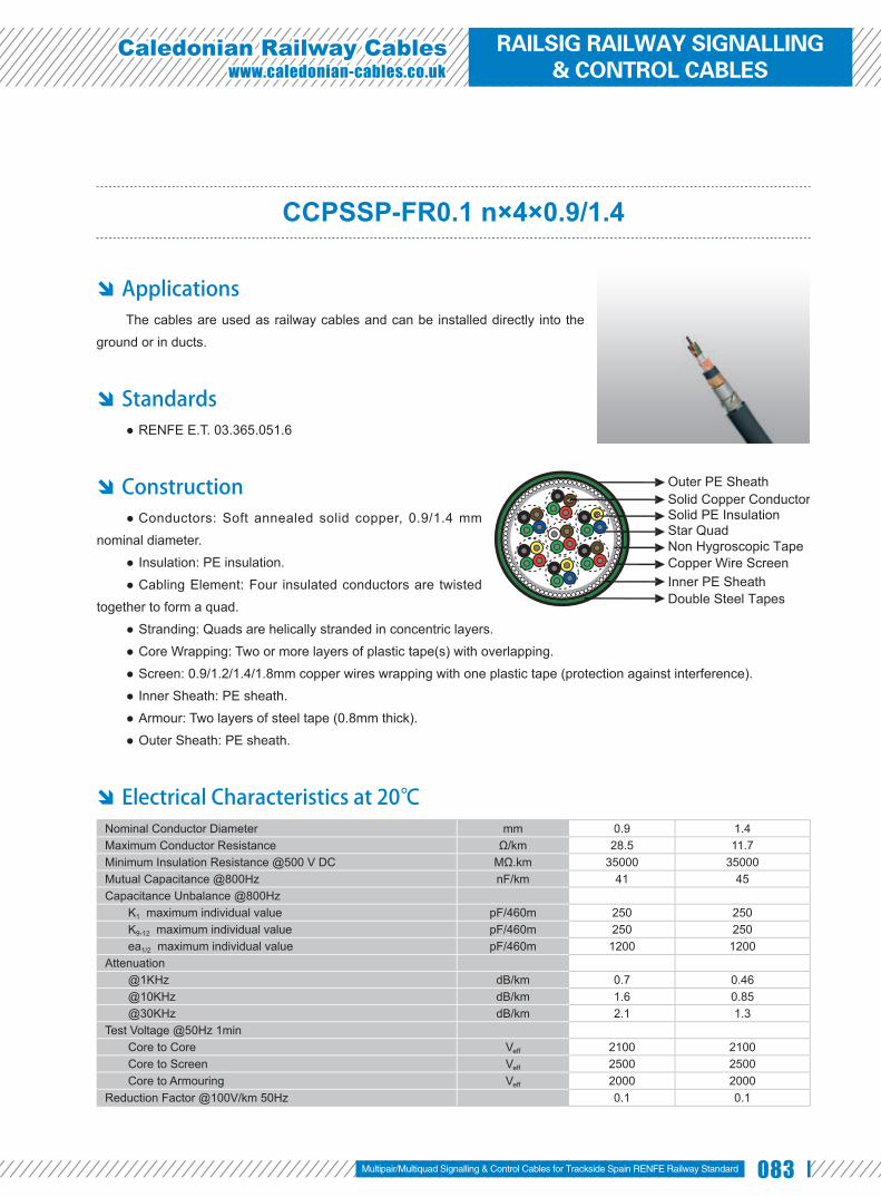
083
Caledonian Railway Cableswww.caledonian-cables.co.uk
CCPSSP-FR0.1 n×4×0.9/1.4
Applications The cables are used as railway cables and can be installed directly into the
ground or in ducts.
Standards RENFE E.T. 03.365.051.6 ●
Construction Conductors: Soft annealed solid copper, 0.9/1.4 mm ●
nominal diameter.
Insulation: PE insulation. ●
Cabling Element: Four insulated conductors are twisted ●
together to form a quad.
Stranding: Quads are helically stranded in concentric layers. ●
Core Wrapping: Two or more layers of plastic tape(s) with overlapping. ●
Screen: 0.9/1.2/1.4/1.8mm copper wires wrapping with one plastic tape (protection against interference). ●
Inner Sheath: PE sheath. ●
Armour: Two layers of steel tape (0.8mm thick). ●
Outer Sheath: PE sheath. ●
Electrical Characteristics at 20℃ Nominal Conductor Diameter mm 0.9 1.4Maximum Conductor Resistance Ω/km 28.5 11.7Minimum Insulation Resistance @500 V DC MΩ.km 35000 35000Mutual Capacitance @800Hz nF/km 41 45Capacitance Unbalance @800Hz
K1 maximum individual value pF/460m 250 250K9-12 maximum individual value pF/460m 250 250ea1/2 maximum individual value pF/460m 1200 1200
Attenuation @1KHz dB/km 0.7 0.46@10KHz dB/km 1.6 0.85@30KHz dB/km 2.1 1.3
Test Voltage @50Hz 1minCore to Core Veff 2100 2100Core to Screen Veff 2500 2500Core to Armouring Veff 2000 2000
Reduction Factor @100V/km 50Hz 0.1 0.1
Solid Copper ConductorSolid PE InsulationStar Quad
Copper Wire ScreenNon Hygroscopic Tape
Inner PE Sheath
Outer PE Sheath
Double Steel Tapes
Multipair/Multiquad Signalling & Control Cables for Trackside Spain RENFE Railway Standard
RAILSIG RAILWAY SIGNALLING & CONTROL CABLES

084 www.addison-cables.com
Mechanical and Thermal Properties Minimum Bending Radius: 10×OD ●
Temperature Range: -40℃ to +60℃ (during operation); -10℃ to +60℃ (during installation) ●
Dimensions and Weight
Cable Code Number of Quads
Nominal Sheath Thickness mm
Maximum Overall Diameter
mm
Nominal Weightkg/km
Inner Outer0.9mm Conductor, 1.8mm Insulated Wire
RS/CCPSSP-FR0.1-2YD2YB2Y-1Q0.9 1 1.5 1.6 21.2 1140RS/CCPSSP-FR0.1-2YD2YB2Y-3Q0.9 3 1.5 1.6 24.5 1370RS/CCPSSP-FR0.1-2YD2YB2Y-5Q0.9 5 1.5 1.6 27.0 1610RS/CCPSSP-FR0.1-2YD2YB2Y-7Q0.9 7 1.5 1.6 28.4 1750RS/CCPSSP-FR0.1-2YD2YB2Y-10Q0.9 10 1.5 1.6 32.1 2060RS/CCPSSP-FR0.1-2YD2YB2Y-12Q0.9 12 1.5 1.6 32.1 2130RS/CCPSSP-FR0.1-2YD2YB2Y-14Q0.9 14 1.6 1.8 35.3 2380RS/CCPSSP-FR0.1-2YD2YB2Y-19Q0.9 19 1.7 1.8 38.6 2760RS/CCPSSP-FR0.1-2YD2YB2Y-25Q0.9 25 1.7 1.8 42.0 3150
1.4mm Conductor, 2.7mm Insulated WireRS/CCPSSP-FR0.1-2YD2YB2Y-1Q1.4 1 1.5 1.6 22.7 1280RS/CCPSSP-FR0.1-2YD2YB2Y-3Q1.4 3 1.5 1.6 28.0 1690RS/CCPSSP-FR0.1-2YD2YB2Y-5Q1.4 5 1.6 1.8 32.0 2070RS/CCPSSP-FR0.1-2YD2YB2Y-7Q1.4 7 1.6 1.8 33.9 2320RS/CCPSSP-FR0.1-2YD2YB2Y-10Q1.4 10 1.6 1.8 39.2 2860RS/CCPSSP-FR0.1-2YD2YB2Y-12Q1.4 12 1.7 1.8 39.2 2980RS/CCPSSP-FR0.1-2YD2YB2Y-14Q1.4 14 1.7 1.8 42.6 3340RS/CCPSSP-FR0.1-2YD2YB2Y-19Q1.4 19 1.8 2.0 48.5 4160
UV Resistant Water Resistant Rated Voltage
300/500V
Buried in Ciround Laid In Ducts Zero HalogenIEC 60754-1/NF C20-454
EN 50267-2-1
Zero
Anti Induction
EMI

085
Caledonian Railway Cableswww.caledonian-cables.co.uk
CCPSSP-R-FR0.1
Applications The cables are used as railway cables and can be installed directly into the
ground or in ducts.
Standards RENFE E.T. 03.365.051.6 ●
Construction Conductors: Soft annealed solid copper, 0.9 mm nominal ●
diameter. Insulation: PE insulation. ●Cabling Element: Four insulated conductors are twisted ●
together to form a quad.Stranding: Quads are helically stranded in concentric layers. ●Filling: Petroleum jelly fi lling. ●Core Wrapping: At least one layer of water swellable material with overlapping. ●Inner Sheath: PE sheath. ●Screen: 1.4/1.8mm copper wires wrapping with one plastic tape (protection against interference). ●Intermediate Sheath: PE sheath. ●Armour: Two layers of steel tape (0.8mm thick). ●Outer Sheath: PE sheath. ●
Electrical Characteristics at 20℃ Nominal Conductor Diameter mm 0.9Maximum Conductor Resistance Ω/km 28.5Minimum Insulation Resistance @500 V DC MΩ.km 25000Mutual Capacitance @800Hz nF/km 41Capacitance Unbalance @800Hz K1 maximum individual value pF/460m 250 K9-12 maximum individual value pF/460m 250 ea1/2 maximum individual value pF/460m 1200Attenuation @1KHz dB/km 0.7 @10KHz dB/km 1.6 @30KHz dB/km 2.1Test Voltage @50Hz 1min Core to Core Veff 2100 Core to Screen Veff 2500 Core to Armouring Veff 2000Reduction Factor @100V/km 50Hz 0.1
Solid Copper ConductorSolid PE InsulationPetroleum Jelly Filling
Copper Wire Screen
Non Hygroscopic Tape
Intermediate PE SheathOuter PE Sheath
Double Steel Tapes
Star Quad
Inner PE Sheath
Multipair/Multiquad Signalling & Control Cables for Trackside Spain RENFE Railway Standard
RAILSIG RAILWAY SIGNALLING & CONTROL CABLES

086 www.addison-cables.com
Mechanical and Thermal Properties Minimum Bending Radius: 10×OD ●
Temperature Range: -30℃ to +70℃ (during operation); -5℃ to +50℃ (during installation) ●
Dimensions and Weight
Cable Code Number of Quads
Nominal Sheath Thickness mm
Maximum Overall Diameter
mm
Nominal Weightkg/kmInner Inter. Outer
0.9mm Conductor, 1.8mm Insulated WireRS/CCPSSP-R-FR0.1-2Y(F)2YD2YB2Y-1Q0.9 1 1.5 1.5 1.6 23.7 1300RS/CCPSSP-R-FR0.1-2Y(F)2YD2YB2Y-3Q0.9 3 1.5 1.5 1.6 27.7 1648RS/CCPSSP-R-FR0.1-2Y(F)2YD2YB2Y-5Q0.9 5 1.5 1.5 1.6 31.5 1984RS/CCPSSP-R-FR0.1-2Y(F)2YD2YB2Y-25Q0.9 25 1.7 1.7 1.8 51.3 4166
UV Resistant Water Resistant Rated Voltage
300/500V
Buried in Ciround Laid In Ducts Zero HalogenIEC 60754-1/NF C20-454
EN 50267-2-1
Zero
Anti Induction
EMI

087
Caledonian Railway Cableswww.caledonian-cables.co.uk
CCTSST-FR0.1 n×4×0.9/1.4
Applications The cables are used as railway cables and can be installed directly into the
ground or in ducts.
Standards RENFE E.T. 03.365.051.6 ●
Construction Conductors: Soft annealed solid copper, 0.9/1.4 mm ●
nominal diameter.
Insulation: PE insulation. ●
Cabling Element: Four insulated conductors are twisted ●
together to form a quad.
Stranding: Quads are helically stranded in concentric layers. ●
Core Wrapping: Two or more layers of plastic tape(s) with overlapping. ●
Screen: 0.9/1.2/1.4/1.8mm copper wires wrapping with one plastic tape (protection against interference). ●
Inner Sheath: LSZH sheath, coloured green. ●
Armour: Two layers of steel tape (0.8mm thick). ●
Outer Sheath: LSZH sheath, coloured green. ●
Electrical Characteristics at 20℃ Nominal Conductor Diameter mm 0.9 1.4Maximum Conductor Resistance Ω/km 28.5 11.7Minimum Insulation Resistance @500 V DC MΩ.km 35000 35000Mutual Capacitance @800Hz nF/km 41 45Capacitance Unbalance @800Hz
K1 maximum individual value pF/460m 250 250K9-12 maximum individual value pF/460m 250 250ea1/2 maximum individual value pF/460m 1200 1200
Attenuation @1KHz dB/km 0.7 0.46@10KHz dB/km 1.6 0.85@30KHz dB/km 2.1 1.3
Test Voltage @50Hz 1minCore to Core Veff 2100 2100Core to Screen Veff 2500 2500Core to Armouring Veff 2000 2000
Reduction Factor @100V/km 50Hz 0.1 0.1
Solid Copper ConductorSolid PE InsulationStar Quad
Copper Wire ScreenNon Hygroscopic Tape
Inner ZHLS Sheath
Outer ZHLS Sheath
Double Steel Tapes
Multipair/Multiquad Signalling & Control Cables for Trackside Spain RENFE Railway Standard
RAILSIG RAILWAY SIGNALLING & CONTROL CABLES

088 www.addison-cables.com
Mechanical and Thermal Properties Minimum Bending Radius: 10×OD ●
Temperature Range: -40℃ to +60℃ (during operation); -10℃ to +60℃ (during installation) ●
Dimensions and Weight
Cable Code Number of Quads
Nominal Sheath Thickness mm
Maximum Overall Diameter
mm
Nominal Weightkg/kmInner Outer
0.9mm Conductor, 1.8mm Insulated WireRS/CCTSST-FR0.1-2YDHBH-1Q0.9 1 1.5 1.6 20.6 1170RS/CCTSST-FR0.1-2YDHBH-3Q0.9 3 1.5 1.6 24.7 1480RS/CCTSST-FR0.1-2YDHBH-5Q0.9 5 1.5 1.6 27.3 1740RS/CCTSST-FR0.1-2YDHBH-7Q0.9 7 1.5 1.6 29.6 1950RS/CCTSST-FR0.1-2YDHBH-10Q0.9 10 1.5 1.6 33.5 2320RS/CCTSST-FR0.1-2YDHBH-25Q0.9 25 1.7 1.8 44.2 3590
1.4mm Conductor, 2.7mm Insulated WireRS/CCTSST-FR0.1-2YDHBH-10Q1.4 10 1.6 1.8 39.2 3140
Anti Induction
EMIUV Resistant Water Resistant Rated Voltage
300/500V
Buried in Ciround Laid In Ducts
Flame RetardantNF C32-070-2.1(C2)
IEC 60332-1/EN 50265-2-1NF C32-070-2.2(C1)
IEC 60332-3/EN50266
Fire Retardant Zero HalogenIEC 60754-1/NF C20-454
EN 50267-2-1
Zero
Low Smoke EmissionIEC 61034/NFC20-902EN 50268/NF C32-073
EN 50267-2-2/NF C32-074IEC 60754-2/NF C20-453
Low Corrosivity Low Toxicity

089
Caledonian Railway Cableswww.caledonian-cables.co.uk
CCTSST-FR0.3 n×4×1.4
Applications The cables are used as railway cables and can be installed directly into the
ground or in ducts.
Standards RENFE E.T. 03.365.051.6 ●
Construction Conductors: Soft annealed solid copper, 1.4 mm nominal ●
diameter.
Insulation: PE insulation. ●
Cabling Element: Four insulated conductors are twisted ●
together to form a quad.
Stranding: Quads are helically stranded in concentric layers. ●
Core Wrapping: Two or more layers of plastic tape(s) with overlapping. ●
Screen: Copper tapes with overlap (protection against interference). ●
Inner Sheath: LSZH sheath, coloured green. ●
Armour: Two layers steel tape (0.8mm thick). ●
Outer Sheath: LSZH sheath, coloured green. ●
Electrical Characteristics at 20℃ Nominal Conductor Diameter mm 1.4Maximum Conductor Resistance Ω/km 11.7Minimum Insulation Resistance @500 V DC MΩ.km 35000Mutual Capacitance @800Hz nF/km 45Capacitance Unbalance @800Hz
K1 maximum individual value pF/460m 250K9-12 maximum individual value pF/460m 250ea1/2 maximum individual value pF/460m 1200
Test Voltage @50Hz 1minCore to Core Veff 2100Core to Screen Veff 2500
Reduction Factor @100V/km 50Hz 0.3
Mechanical and Thermal Properties Minimum Bending Radius: 10×OD ●
Temperature Range: -40℃ to +60℃ (during operation); -10℃ to +60℃ (during installation) ●
Solid Copper ConductorSolid PE InsulationStar Quad
Copper TapeNon Hygroscopic Tape
Inner ZHLS Sheath
Outer ZHLS Sheath
Double Steel Tapes
Multipair/Multiquad Signalling & Control Cables for Trackside Spain RENFE Railway Standard
RAILSIG RAILWAY SIGNALLING & CONTROL CABLES

090 www.addison-cables.com
Dimensions and Weight
Cable Code Number of Quads
Nominal Sheath Thickness mm
Maximum Overall Diameter
mm
Nominal Weightkg/km
Inner Outer1.4mm Conductor, 2.6mm Insulated Wire
RS/CCTSST-FR0.3-2Y(K)HBH-1Q1.4 1 1.5 1.6 19.0 880RS/CCTSST-FR0.3-2Y(K)HBH-3Q1.4 3 1.5 1.6 27.1 1440RS/CCTSST-FR0.3-2Y(K)HBH-5Q1.4 5 1.5 1.6 31.0 1826RS/CCTSST-FR0.3-2Y(K)HBH-7Q1.4 7 1.5 1.6 33.1 2090RS/CCTSST-FR0.3-2Y(K)HBH-10Q1.4 10 1.7 1.8 38.4 2640RS/CCTSST-FR0.3-2Y(K)HBH-14Q1.4 14 1.7 1.8 42.2 3168RS/CCTSST-FR0.3-2Y(K)HBH-19Q1.4 19 1.8 2.0 47.2 3861
Anti Induction
EMIUV Resistant Water Resistant Rated Voltage
300/500V
Buried in Ciround Laid In Ducts
Flame RetardantNF C32-070-2.1(C2)
IEC 60332-1/EN 50265-2-1NF C32-070-2.2(C1)
IEC 60332-3/EN50266
Fire Retardant Zero HalogenIEC 60754-1/NF C20-454
EN 50267-2-1
Zero
Low Smoke EmissionIEC 61034/NFC20-902EN 50268/NF C32-073
EN 50267-2-2/NF C32-074IEC 60754-2/NF C20-453
Low Corrosivity Low Toxicity

091
Caledonian Railway Cableswww.caledonian-cables.co.uk
SXCAV & SXCAG Signalling Cables
Applications The cables are designed for connection between switching centers and
equipment shelters along the trackside. The cables are used as main signalling
cables specially designed to give good induction protection (R.F=0.24 at inductive
voltage 170 V/km) and are suitable for installation in intercity railways electrifi ed at
25KV ac.
Standards SXCAV SXCAG Specifi cation ●
Fire performance: EN 50266-2-4 C ●
Construction Conductors: Class 1 solid bare copper conductor. ●
Insulation: Coloured cross-linked PE insulation. ●
Cabling Element: Each two conductors are twisted together to form a pair. ●
Stranding: Pairs are helically stranded in layers to form the cable core. ●
Core Wrapping: Plastic tape(s) with overlapping. ●
Inner Sheath: PE sheath. ●
Electrostatic Shield: One corrugated copper tape. ●
Intermediate Sheath: PE sheath. ●
Electromagnetic Shield: Two helically applied steel tapes. ●
Outer Sheath: Black unleaded PVC (SXCAV) or green halogen free (SXCAG) sheath. ●
Electrical Characteristics at 20℃ Nominal Conductor Diameter mm 1.38Nominal Cross Section Area mm² 1.5Maximum Conductor Resistance (DC) Ω/km 12.3Minimum Insulation Resistance @500 V DC (3mins) MΩ.km 10000Maximum Mutual Capacitance @1000Hz (AC) nF/km 60Maximum Reduction Factor @170V/km 50Hz 0.24Operating Voltage V 1000
Mechanical and Thermal Properties Minimum Bending Radius: 10×OD ●
Temperature Range: -25℃ to +90℃ (during operation); -10℃ to +90℃ (during installation) ●
Solid Copper ConductorCross-linked PE InsulationTwisted PairNon Hygroscopic TapeInner PE SheathCorrugated Copper TapeIntermediate PE Sheath
Outer PVC/LSZH SheathDouble Steel Tapes
Multipair/Multiquad Signalling & Control Cables for Trackside Belgium SNCB Railway Standard
RAILSIG RAILWAY SIGNALLING & CONTROL CABLES

092 www.addison-cables.com
Dimensions and Weight SXCAV Cables
Cable Code Number of Pairs
Nominal Sheath Thickness mm
Nominal Overall Diameter
mm
Nominal Weightkg/km
Inner Inter. Outer1.38mm Conductor, 2.38mm Insulated Wire
RS/SXCAV-2Y2Y(K)2YBY-1P1.5S 1 1.0 0.8 1.6 16.9 513RS/SXCAV-2Y2Y(K)2YBY-4P1.5S 4 1.0 0.8 1.6 23.1 826RS/SXCAV-2Y2Y(K)2YBY-7P1.5S 7 1.0 0.8 1.7 26.1 1060RS/SXCAV-2Y2Y(K)2YBY-14P1.5S 14 1.2 0.8 1.8 32.3 1571RS/SXCAV-2Y2Y(K)2YBY-24P1.5S 24 1.2 1.1 2.0 38.3 2199RS/SXCAV-2Y2Y(K)2YBY-30P1.5S 30 1.2 1.1 2.2 42.8 2555
SXCAG Cables
Cable Code Number of Pairs
Nominal Sheath Thicknessmm
Nominal Overall Diameter
mm
Nominal Weightkg/km
Inner Inter. Outer1.38mm Conductor, 2.38mm Insulated Wire
RS/SXCAG-2Y2Y(K)2YBH-1P1.5S 1 1.0 0.8 1.6 16.9 515RS/SXCAG-2Y2Y(K)2YBH-4P1.5S 4 1.0 0.8 1.6 23.1 855RS/SXCAG-2Y2Y(K)2YBH-7P1.5S 7 1.0 0.8 1.7 26.1 1095RS/SXCAG-2Y2Y(K)2YBH-14P1.5S 14 1.2 0.8 1.8 32.3 1616RS/SXCAG-2Y2Y(K)2YBH-24P1.5S 24 1.2 1.1 2.0 38.3 2260RS/SXCAG-2Y2Y(K)2YBH-30P1.5S 30 1.2 1.1 2.2 42.8 2625
Anti Induction
EMIBuried in Ciround Laid In Ducts
PVC Sheath
LSZH Sheath
Flame RetardantNF C32-070-2.1(C2)
IEC 60332-1/EN 50265-2-1
Flame RetardantNF C32-070-2.1(C2)
IEC 60332-1/EN 50265-2-1NF C32-070-2.2(C1)
IEC 60332-3/EN50266
Fire Retardant Zero HalogenIEC 60754-1/NF C20-454
EN 50267-2-1
Zero
Low Smoke EmissionIEC 61034/NFC20-902EN 50268/NF C32-073
EN 50267-2-2/NF C32-074IEC 60754-2/NF C20-453
Low Corrosivity Low Toxicity

093
Caledonian Railway Cableswww.caledonian-cables.co.uk
SW-CLT Switching Centre Cables
Applications The cables are used as block cables for railway. The cables are suitable
for connection between local switching centre and the trackside and signalling
equipments.
Standards CFF: I-EB-SK 3001.82.1000 ●
Construction Conductors: Class 1 solid copper, 1.0/1.5/2.2mm ●
nominal diameter.
Insulation: Solid polyethylene. ●
Cabling Element: Four conductors are twisted ●
together to form a quad.
Inner Sheath: PE sheath. ●
Armour: Double galvanized steel tapes of 0.15mm. ●
Outer Sheath: PE/LSZH sheath. ●
Optional Unarmoured Cable: The cables offered without galvanized steel tapes (SW).
Traction Armoured Cable: The cables offered with galvanized steel fl at wire armour with or without protection sheath
(SW-F/FT).
Halogenfree Sheathed Cable: The cables offered with LSZH sheath according to IEC 60332-3C (SW-CLN/FN).
Electrical Characteristics at 20℃ Nominal Conductor Diameter mm 1.0 1.5 2.2Maximum Conductor Resistance (DC) Ω/km 47.0 20.9 10.0Minimum Insulation Resistance @500 V DC (3mins) MΩ.km 10000 10000 10000Maximum Mutual Capacitance @800Hz nF/km 42 52 60Maximum Capacitance Unbalance
In quad pF/km 400 400 400Between quads pF/km 400 400 400Real-ground pF/km 650 650 650
Operating Voltage AC/DC V 500/800
Solid Copper Conductor
Solid PE Insulation
Inner PE Sheath
Star Quad
Outer PE/LSZH Sheath
Double Galvanized Steel Tapes
Multipair/Multiquad Signalling & Control Cables for Trackside Swiss SBB Railway Standard
RAILSIG RAILWAY SIGNALLING & CONTROL CABLES

094 www.addison-cables.com
Mechanical and Thermal Properties Minimum Bending Radius: 10×OD ●
Temperature Range: -30℃ to +60℃ (during operation); -10℃ +60℃ (during installation) ●
Dimensions and Weight
Cable Code No. of Quads
Nominal Sheath Thicknessmm
Nominal Overall Diameter
mm
Nominal Weightkg/km
Inner Outer1.0mm Conductor, 1.8mm Insulated Wire
RS/SW-CLT-2Y2YB2Y-1Q1 1 1.0 1.5 12.7 161RS/SW-CLT-2Y2YB2Y-2Q1 2 1.0 1.5 17.5 335RS/SW-CLT-2Y2YB2Y-3Q1 3 1.0 1.7 18.3 390RS/SW-CLT-2Y2YB2Y-4Q1 4 1.0 1.7 20.4 455RS/SW-CLT-2Y2YB2Y-5Q1 5 1.0 1.7 21.7 543RS/SW-CLT-2Y2YB2Y-7Q1 7 1.2 1.8 23.3 640RS/SW-CLT-2Y2YB2Y-10Q1 10 1.2 2.0 28.4 896RS/SW-CLT-2Y2YB2Y-15Q1 15 1.2 2.2 33.0 1260RS/SW-CLT-2Y2YB2Y-20Q1 20 1.2 2.3 37.1 1590RS/SW-CLT-2Y2YB2Y-25Q1 25 1.2 2.4 41.7 1960RS/SW-CLT-2Y2YB2Y-30Q1 30 1.3 2.5 43.2 2130
1.5mm Conductor, 2.8mm Insulated WireRS/SW-CLT-2Y2YB2Y-1Q1.5 1 1.0 1.5 15.1 240RS/SW-CLT-2Y2YB2Y-2Q1.5 2 1.0 1.5 23.6 491RS/SW-CLT-2Y2YB2Y-3Q1.5 3 1.0 1.7 24.4 585RS/SW-CLT-2Y2YB2Y-4Q1.5 4 1.0 1.7 27.5 684RS/SW-CLT-2Y2YB2Y-5Q1.5 5 1.0 1.7 30.5 793RS/SW-CLT-2Y2YB2Y-7Q1.5 7 1.2 1.8 32.9 1030RS/SW-CLT-2Y2YB2Y-10Q1.5 10 1.2 2.0 42.5 1460RS/SW-CLT-2Y2YB2Y-15Q1.5 15 1.2 2.2 49.2 2060RS/SW-CLT-2Y2YB2Y-20Q1.5 20 1.2 2.3 57.0 2600RS/SW-CLT-2Y2YB2Y-25Q1.5 25 1.2 2.4 62.8 3300RS/SW-CLT-2Y2YB2Y-30Q1.5 30 1.3 2.5 64.4 3660
2.2mm Conductor, 3.8mm Insulated WireRS/SW-CLT-2Y2YB2Y-1Q2.2 1 1.0 1.5 13.1 346RS/SW-CLT-2Y2YB2Y-2Q2.2 2 1.0 1.5 20.4 573RS/SW-CLT-2Y2YB2Y-3Q2.2 3 1.0 1.7 21.4 934RS/SW-CLT-2Y2YB2Y-4Q2.2 4 1.0 1.7 23.1 1329RS/SW-CLT-2Y2YB2Y-5Q2.2 5 1.0 1.7 25.5 1380RS/SW-CLT-2Y2YB2Y-7Q2.2 7 1.2 1.8 27.4 1730RS/SW-CLT-2Y2YB2Y-10Q2.2 10 1.2 2.0 33.7 2560RS/SW-CLT-2Y2YB2Y-15Q2.2 15 1.2 2.2 39.2 3630RS/SW-CLT-2Y2YB2Y-20Q2.2 20 1.2 2.3 43.4 4780RS/SW-CLT-2Y2YB2Y-25Q2.2 25 1.2 2.4 50.1 5850RS/SW-CLT-2Y2YB2Y-30Q2.2 30 1.3 2.5 51.8 6580
Anti Induction
EMIUV Resistant Water Resistant Zero Halogen
IEC 60754-1/NF C20-454EN 50267-2-1
Zero
Buried in Ciround Laid In Ducts

095
Caledonian Railway Cableswww.caledonian-cables.co.uk
Twin Datalink Cable
Application The cables are used as interconnecting cables for Solid State Interlocking
(SSI) systems.
Standards BR 1932 ●
Construction Conductors: Class 1 solid plain copper ●
conductor, 1.27mm nominal diameter.Insulation: Solid polyethylene. ●Inner Sheath: Low density polyethylene. ●Moisture Barrier: PE Copolymer coated ●
aluminium tape.Sheath: Low density polyethylene. ●Core Identifi cation: Blue & Red. ●
Electrical Characteristics at 20℃ Nominal Conductor Diameter mm 1.27Nominal Conductor Cross Section mm² 2.5Maximum Conductor Resistance Ω/km 7.41
Mechanical and Thermal Properties Minimum Bending Radius: 6×OD ●
Temperature Range: -25℃ to +85℃ (during operation); -10℃ to +85℃ (during installation) ●
Dimensions and Weight
Cable Code No. of pairsNominal Sheath
Thickness mm
Overall DiameterMin/Max
mm
Nominal Weightkg/km
1.27mm Conductor, 2.59mm Insulation WireRS1932-2Y2Y(L)2Y-1P1.27 1 2.5 12.47/12.8 136
Solid PE Insulation
Inner PE Sheath
Solid Copper Conductor
PE-copolymer Coated Aluminium Tape
Outer PE Sheath
Anti Induction
EMIUV Resistant Water Resistant Zero Halogen
IEC 60754-1/NF C20-454EN 50267-2-1
Zero
Buried in Ciround Laid In DuctsRated Voltage
300/500V
Multipair/Multiquad Signalling & Control Cables for Trackside UK NETWORK RAIL Standard
RAILSIG RAILWAY SIGNALLING & CONTROL CABLES

096 www.addison-cables.com
RT/F3 D & S & B type Axle Counter Cable
Applications The cables are designed for transmission of signals up to 90 kHz in axle
counter train detection systems.
Standards RT/E/PS/00031 ●
Construction Conductors: Tinned copper, 0.9/1.4 mm ●
nominal diameter.
Insulation: Solid polyethylene. ●
Cabling Element: Two insulated conductors ●
are twisted together to form a pair.
Stranding: Pairs are helically stranded in ●
concentric layers.
Filling: Cable core interstices are filled ●
with a low-permitivity compound. Unfi lled cables
option can be offered upon request.
Core Wrapping: Plastic tape(s) with ●
overlapping.
Moisture Barrier: One laminated sheath ●
made of aluminium tape coated with PE-
Copolymer on at least one side is applied with
longitudinally overlap.
Inner Sheath (for S/B type): Polyethylene or LSZH fi re retardant compound. ●
Mechanical Protection (for S/B type): One corrugated steel tape or brass tape is longitudinally applied with ●
overlap. Unarmoured cables option can be offered upon request.
Outer Sheath: Polyethylene or LSZH fi re retardant compound. Ruggedised PE sheath compound can be offered ●
upon request.
Type Codes F1 class: Non LSZH cables.
F5 class: Unfi lled cables
D type: Unarmoured types
R type: Ruggedised PE sheath
Solid Copper ConductorSolid PE InsulationTwisted Pair
Non Hygroscopic TapeOptional Petroleum Jelly
PE/LSZH Sheath
PE-copolymer Coated Aluminium Tape
Solid Copper ConductorSolid PE InsulationTwisted Pair
Non Hygroscopic Tape
Inner PE/LSZH Sheath
Optional Petroleum Jelly
Outer PE/LSZH Sheath
PE-copolymer Coated Aluminium TapeCorrugated Steel/Brass Tape

097
Caledonian Railway Cableswww.caledonian-cables.co.uk
S type: Steel tape armoured types
B type: Brass tape armoured types
E1, E2 & E3 types: 3 different induction protection levels available.
Electrical Characteristics at 20℃ Nominal Conductor Diameter mm 0.9 1.4Nominal Conductor Cross Section mm² 0.63 1.5Maximum Conductor Resistance Ω/km 30.0 12.5Minimum Insulation Resistance @500 V DC (1min) MΩ.km 5000 5000Nominal Conductor Capacitance @800Hz/1000Hz (AC) nF/km 42+3 47+3Dielectric Strength, conductor to screen (DC voltage 2mins) V 3000 3000Maximum Average Attenuation
@1.0KHz dB/km 0.73 [email protected] dB/km 1.10 0.62@40KHz dB/km 2.88 1.77@90KHz dB/km 3.70 [email protected] dB/km 11.2 7.45
Minimum Average Near-end Crosstalk @1.0KHz dB/km 60 [email protected] dB/km 60 60@40KHz dB/km 50 50@90KHz dB/km 50 [email protected] dB/km 35 35
Mechanical and Thermal Properties Minimum Bending Radius: 7.5×OD (unarmoured); 10×OD (armoured) ●
Temperature Range: -30℃ to +60℃ (during operation); -10℃ to +60℃ (during installation) ●
Core Identification
Pair Number A Wire B Wire Pair Number A Wire B Wire1 WHITE BLUE 13 YELLOW GREEN2 WHITE ORANGE 14 YELLOW BROWN3 WHITE GREEN 15 YELLOW GREY4 WHITE BROWN 16 VIOLET BLUE5 WHITE GREY 17 VIOLET ORANGE6 RED BLUE 18 VIOLET GREEN7 RED ORANGE 19 VIOLET BROWN8 RED GREEN 20 VIOLET GREY9 RED BROWN 21 TURQUOISE BLUE10 RED GREY 22 TURQUOISE ORANGE11 YELLOW BLUE 23 TURQUOISE GREEN12 YELLOW ORANGE 24 TURQUOISE BROWN
Two pair cables laid up in quad formation colour coded in rotation, Orange, White, Green, Black
Axle Counter Cables UK NETWORK RAIL Standard
RAILSIG RAILWAY SIGNALLING & CONTROL CABLES

098 www.addison-cables.com
Dimensions and Weight A-2Y(F)(L)2Y n×2×0.9/1.4 Cables
Cable Code Number of Pairs(n)
Nominal Sheath Thickness mm
Maximum Overall Diameter
mm
Nominal Weightkg/km
0.9mm Conductor, 1.55mm Insulated WireRS/RT/F3-D-2Y(F)(L)2Y-2P0.9 2 2.4 13.2 210RS/RT/F3-D-2Y(F)(L)2Y-10P0.9 10 2.4 21.6 530RS/RT/F3-D-2Y(F)(L)2Y-12P0.9 12 2.4 24.8 580RS/RT/F3-D-2Y(F)(L)2Y-19P0.9 19 2.4 31.2 800RS/RT/F3-D-2Y(F)(L)2Y-24P0.9 24 2.4 33.8 980
1.4mm Conductor, 2.2mm Insulated WireRS/RT/F3-D-2Y(F)(L)2Y-2P1.4 2 2.4 23.4 320RS/RT/F3-D-2Y(F)(L)2Y-10P1.4 10 2.4 30.0 910RS/RT/F3-D-2Y(F)(L)2Y-12P1.4 12 2.4 32.0 1101RS/RT/F3-D-2Y(F)(L)2Y-19P1.4 19 2.4 37.3 1450RS/RT/F3-D-2Y(F)(L)2Y-24P1.4 24 2.4 42.3 1780
A-2Y(L)2YB2Y n×2×0.9/1.4 Cables
Cable CodeNumber of
Pairs(n)
Nominal Sheath Thickness mm
Maximum Overall Diameter
mm
Nominal Weightkg/km
Inner Outer0.9mm Conductor, 1.8mm Insulated Wire
RS/RT/F3-S-2Y(L)2YB2Y-2P0.9 2 2.2 2.4 22.0 399RS/RT/F3-S-2Y(L)2YB2Y-10P0.9 10 2.2 2.4 30.4 880RS/RT/F3-S-2Y(L)2YB2Y-12P0.9 12 2.2 2.4 33.6 963RS/RT/F3-S-2Y(L)2YB2Y-19P0.9 19 2.2 2.4 40.0 1312RS/RT/F3-S-2Y(L)2YB2Y-24P0.9 24 2.2 2.4 42.6 1626
1.4mm Conductor , 2.7mm Insulated WireRS/RT/F3-S-2Y(L)2YB2Y-2P1.4 2 2.2 2.4 32.2 608RS/RT/F3-S-2Y(L)2YB2Y-10P1.4 10 2.2 2.4 38.8 1510RS/RT/F3-S-2Y(L)2YB2Y-12P1.4 12 2.2 2.4 40.8 1827RS/RT/F3-S-2Y(L)2YB2Y-19P1.4 19 2.2 2.4 46.1 2380RS/RT/F3-S-2Y(L)2YB2Y-24P1.4 24 2.2 2.4 51.1 2954
UV Resistant Water Resistant Rated voltage
750V DC/450V AC
Impact Resistant Buried in Ciround Laid In Ducts
LSZH Sheath
Flame RetardantNF C32-070-2.1(C2)
IEC 60332-1/EN 50265-2-1NF C32-070-2.2(C1)
IEC 60332-3/EN50266
Fire Retardant
PE Sheath
Zero HalogenIEC 60754-1/NF C20-454
EN 50267-2-1
Zero
Zero HalogenIEC 60754-1/NF C20-454
EN 50267-2-1
Zero
Low Smoke EmissionIEC 61034/NFC20-902EN 50268/NF C32-073
EN 50267-2-2/NF C32-074IEC 60754-2/NF C20-453
Low Corrosivity Low Toxicity

099
Caledonian Railway Cableswww.caledonian-cables.co.uk
RT/F3 E1/E2/E3 Type Axle Counter Cable
Applications The cables are designed for transmission of signals up to 90 kHz in axle
counter train detection systems.
Standards RT/E/PS/00031 ●
Construction Conductors: Tinned copper wire, 0.9 or ●
1.4 mm nominal diameter.Insulation: Solid polyethylene. ●Cab l ing E lement : Two insu la ted ●
conductors are twisted together to form a pair.Stranding: Pairs are helically stranded in ●
concentric layers.Filling: Cable core interstices are fi lled with a low-permitivity compound. Unfi lled cables option can be offered upon ●
request.Core Wrapping: Plastic tape(s) with overlapping. ●Moisture Barrier: One laminated sheath made of aluminium tape coated with PE-Copolymer on at least one side ●
is applied with longitudinally overlap.Inner Sheath: Polyethylene or LSZH fi re retardant compound. ●Electrostatic Shield: One layer of helically applied copper wires. ●Electromagnetic Shield: Two helically applied steel tapes. ●Outer Sheath: Polyethylene or LSZH fi re retardant compound. Ruggedised PE sheath compound can be offered ●
upon request.
Type Codes F1 class: Non LSZH cables F5 class: Unfi lled cables
D type: Unarmoured types R type: Ruggedised PE sheath
S type: Steel tape armoured types B type: Brass tape armoured types
E1, E2 & E3 types: 3 different induction protection levels available.
Electrical Characteristics at 20℃ Nominal Conductor Diameter mm 0.9 1.4Nominal Conductor Cross Section mm² 0.63 1.5Maximum Conductor Resistance Ω/km 30.0 12.5
Solid Copper ConductorSolid PE InsulationTwisted Pair
Non Hygroscopic Tape
Inner PE/LSZH Sheath
Optional Petroleum Jelly
Outer PE/LSZH Sheath
Double Steel TapesPE-copolymer Coated Aluminium Tape
Copper Wire
Axle Counter Cables UK NETWORK RAIL Standard
RAILSIG RAILWAY SIGNALLING & CONTROL CABLES

100 www.addison-cables.com
Minimum Insulation Resistance @500 V DC (1min) MΩ.km 5000 5000Nominal Mutual Capacitance @800Hz/1000Hz (AC) nF/km 42+3 47+3Dielectric Strength, conductor to screen (DC voltage 2mins) V 3000 3000Maximum Average Attenuation
@1.0KHz dB/km 0.73 [email protected] dB/km 1.10 0.62@40KHz dB/km 2.88 1.77@90KHz dB/km 3.70 [email protected] dB/km 11.2 7.45
Minimum Average Near-end Crosstalk Attenuation @1.0KHz dB/km 60 [email protected] dB/km 60 60@40KHz dB/km 50 50@90KHz dB/km 50 [email protected] dB/km 35 35
Maximum Reduction Factor @100V/km,50HzEMI RF 1 (modest level) 0.65 0.65EMI RF 2 (medium level) 0.45 0.45EMI RF 3 (high level) 0.20 0.20
Mechanical and Thermal Properties Minimum Bending Radius: 7.5×OD (unarmoured); 10×OD (armoured) ●Temperature Range: -30℃ to +60℃ (during operation); -10℃ to +60℃ (during installation) ●
Dimensions and Weight
Cable Code Number of Pairs
Nominal Sheath Thickness mm
Nominal Overall Diameter
mm
Nominal Weightkg/kmInner Outer
0.9mm Conductor , 1.8mm Insulated WireRS/RT/F3-S/E3-2Y(F)(L)2YDB2Y-2P0.9 2 2.2 2.4 23.4 1300RS/RT/F3-S/E3-2Y(F)(L)2YDB2Y-10P0.9 10 2.2 2.4 31.8 1650RS/RT/F3-S/E3-2Y(F)(L)2YDB2Y-12P0.9 12 2.2 2.4 35.0 1760RS/RT/F3-S/E3-2Y(F)(L)2YDB2Y-19P0.9 19 2.2 2.4 41.4 2275RS/RT/F3-S/E3-2Y(F)(L)2YDB2Y-24P0.9 24 2.2 2.4 44.0 2450
1.4mm Conductor, 2.7mm Insulated WireRS/RT/F3-S/E3-2Y(F)(L)2YDB2Y-2P1.4 2 2.2 2.4 33.6 1480RS/RT/F3-S/E3-2Y(F)(L)2YDB2Y-10P1.4 10 2.2 2.4 40.2 2200RS/RT/F3-S/E3-2Y(F)(L)2YDB2Y-12P1.4 12 2.2 2.4 42.2 2325RS/RT/F3-S/E3-2Y(F)(L)2YDB2Y-19P1.4 19 2.2 2.4 47.5 2975RS/RT/F3-S/E3-2Y(F)(L)2YDB2Y-24P1.4 24 2.2 2.4 52.5 3150
UV Resistant Water Resistant Rated voltage
750V DC/450V AC
Impact Resistant Buried in Ciround Laid In DuctsAnti Induction
EMI
LSZH Sheath
Flame RetardantNF C32-070-2.1(C2)
IEC 60332-1/EN 50265-2-1NF C32-070-2.2(C1)
IEC 60332-3/EN50266
Fire Retardant
PE Sheath
Zero HalogenIEC 60754-1/NF C20-454
EN 50267-2-1
Zero
Zero HalogenIEC 60754-1/NF C20-454
EN 50267-2-1
Zero
Low Smoke EmissionIEC 61034/NFC20-902EN 50268/NF C32-073
EN 50267-2-2/NF C32-074IEC 60754-2/NF C20-453
Low Corrosivity Low Toxicity

101
Caledonian Railway Cableswww.caledonian-cables.co.uk
SPFB Speed Control System Cables
Applications The cables are used for the train speed control system (French system KVB).
The cables are laid along railway lines and connect the speed sensors (located between the rails) to the encoder located inside the trackside equipment shelter.
Standards SNCF CT 446 ●
Construction Conductors: Class 2 stranded tinned copper. ●Insulation: Solid polyethylene. ●Cabling Element: Twisted pair. ●Inner Sheath: Low density polyethylene. ●Armour: Galvanized steel braid armour. ●Outer Sheath: Flame Retardant PVC. ●
Electrical Characteristics at 20℃ Nominal Conductor Diameter mm 0.8Nominal Cross Section Area mm² 0.5Maximum Conductor Resistance (DC) Ω/km 36Characteristic Impedance @100KHz Ω 120Maximum Attenuation @50KHz dB/km 5Nominal Insulation Thickness mm 0.55Operating Voltage V 500
Mechanical and Thermal Properties Minimum Bending Radius: 8×OD (static); 16×OD (dynamic) ●Temperature Range: -30℃ to +70℃ (during operation); -20℃ to +50℃ (during installation) ●
Dimensions and Weight
Cable Code
No. of cores& Nominal Conductor Cross Sectional Area
No.×mm²
No. & Nominal Diameter of
StrandsNo/mm
Nominal Sheath Thickness
mm
Nominal Overall
Diametermm
Nominal Weightkg/km
Inner OuterRS/SPFB-2Y2Y(SWB)2Y-2C0.5S 2 x 0.5 7/0.32 1.0 1.5 9.1 97
Stranded Tinned Copper ConductorSolid PE Insulation
Galvanized Steel Braid ArmourInner PE Sheath
Outer FRPVC Sheath
Twisted Pair
Balise Cables French KVB System
Flexible Mineral Oil Resistant
Fuel Oil ResistantOzone Resistant Laid In Ducts/Channel
Flame RetardantNF C32-070-2.1(C2)
IEC 60332-1/EN 50265-2-1
RAILSIG RAILWAY SIGNALLING & CONTROL CABLES

102 www.addison-cables.com
EUROBALISE SIF
Applications The cables are used in Eurobalise (ERTMS) speed control circuits. The
cables are laid in trays alongside railway lines and connect an “Eurobalise” located between the rails to the Eurocoder (LEU) located in a control centre.
Standards ALSTOM 5 326 203 ●SNCF CT 446 ●
Construction Conductors: Class 2 stranded copper. ●Insulation: Solid polyethylene. ●Inner sheath: Low density polyethylene. ●Screen: Two corrugated copper braid ●
shields.Intermediate Sheath : Low density ●
polyethylene.Armour: Galvanized steel braid armour. ●Outer Sheath: Flame Retardant PVC. ●
Electrical Characteristics at 20℃ Nominal Conductor Diameter mm 1.04Nominal Cross Section Area mm² 0.85Maximum Conductor Resistance (DC) Ω/km 22Nominal Characteristic Impedance @100 KHz-1MHz Ω 95Maximum Attenuation
@560 kHz dB/km 7.5@1MHz dB/km 10
Nominal Insulated Thickness mm 0.63
Mechanical and Thermal Properties Minimum Bending Radius: 8×OD (static); 16×OD (dynamic) ●Temperature Range: -30℃ to +70℃ (during operation); -20℃ to +50℃ (during installation) ●
Dimensions and Weight
Cable Code
No. of cores& Nominal Conductor Cross Sectional Area
No.×mm²
No. & Nominal Diameter of
StrandsNo/mm
Nominal Sheath Thickness
mm
Nominal Overall
Diametermm
Nominal Weightkg/km
Inner Inter. OuterRS/SIF-2Y2YC2Y(SWB)Y-2C0.85S 2 x 0.85 7/0.386 1.0 0.8 1.6 15 301
Stranded Copper ConductorSolid PE Insulation
Intermediate PE SheathGalvanized Steel Braid Armour
Outer FRPVC Sheath
Inner PE SheathDouble Corrugated Copper Braid Screen
Mineral Oil Resistant
Fuel Oil Resistant Ozone Resistant Laid In Ducts/Channel
Flame RetardantNF C32-070-2.1(C2)
IEC 60332-1/EN 50265-2-1
Rated voltage
450/750V

103
Caledonian Railway Cableswww.caledonian-cables.co.uk
EUROBALISE BGA
Applications The cables are used as balise cables for ERTMS (European Rail Traffic
Management System) railway networks. The cables are armoured and can provide
low reduction factor.
Standards CEI 20-11 ●
CEI 20-14 ●
CEI 20-29 ●
CEI 20-34 ●
CEI 46-4 ●
CEI 103-10 ●
Construction Conductors: Solid annealed copper, 1.6 mm nominal diameter. ●
Insulation: Solid polyethylene. ●
Stranding: Conductors will be stranded with dielectric fi llers in order to get a circular core shape. ●
Core Wrapping: Plastic tape (s) with overlapping. ●
Inner Sheath: Low density polyethylene. ●
Screen: Aluminium/polyethylene tape longitudinally applied and overlapped. ●
Drain Wire: Tinned copper drain wire ●
Intermediate Sheath: Low density polyethylene. ●
Armour: Two galvanized steel tapes. ●
Outer Sheath: Low density polyethylene. ●
Electrical Characteristics at 20℃ Nominal Conductor Diameter mm 1.6
Maximum Conductor Resistance (DC) Ω/km 21.5
Mutual Capacitance nF/km 42.3+/-15%
Nominal Characteristic Impedance @8.9 KHz Ω 130
Nominal Characteristic Impedance @560 KHz Ω 110
Maximum Attenuation @560 KHz dB/km 3.8
Insulation Resistance MΩ.km 10000
Minimum Dielectric Strength core to screen (DC) V 1000
Minimum Dielectric Strength core to core (DC) V 3000
Reduction Factor @100V/km 50Hz 0.6
Solid Copper Conductor
Intermediate PE Insulation
Core Wrapping
Al/Polyethylene Tape Screen
Outer PE SheathDouble Galvanized Steel Tapes
Inner PE Sheath
Solid PE Insulation
Drain Wire
Balise Cables European ERTMS System
RAILSIG RAILWAY SIGNALLING & CONTROL CABLES

104 www.addison-cables.com
Mechanical and Thermal Properties Minimum Bending Radius: 8×OD (static); 16×OD (dynamic) ●
Temperature Range: -30℃ to +70℃ (during operation); -20℃ to +50℃ (during installation) ●
Dimensions and Weight
Cable Code Number of PairsNominal Sheath Thickness
mmNominal Overall
Diametermm
Nominal Weightkg/km
Inner Inter. Outer1.6mm Conductor, 3.4mm Insulated Wire
RS/BGA-2Y2Y(L)2YB2Y-1P1.6 1 1.0 0.8 1.6 16 334
Anti Induction
EMIUV Resistant Water Resistant Mineral Oil
ResistantRated Voltage
600V DC/420V AC
Laid In Ducts Zero HalogenIEC 60754-1/NF C20-454
EN 50267-2-1
Zero

105
Caledonian Railway Cableswww.caledonian-cables.co.uk
K27 Fire Resisting Control Cables (CR1-C1 Class)
Applications The cables are designed for provide circuit integrity for safety lightning, smoke
extraction, ventilation, emergency telephone and exits during fi re for underground
railways.
Standards RATP K27 specifi cation ●
Fire resistant: class CR1 ●
No fi re propagation: class C1 RATP (<30cm) ●
Construction Conductors: Class 1 solid conductor from ●
1.5mm² to 4mm²; class 2 stranded conductor for 6mm².
Insulation: Silicone rubber insulation. ●
Stranding: Cores are helically stranded in ●
concentric layers.
Inner Sheath: LSZH. ●
Armour: Two layers of steel tape. ●
Outer Sheath: LSZH. ●
Electrical Characteristics at 20℃ Number of strands/Nominal Conductor Diameter mm 7/1.04 1/1.39 1/1.79 1/2.25
Nominal Cross Section Area mm² 6 1.5 2.5 4
Nominal Insulation Thickness mm 1.0 0.8 1.0 1.0
Operating Voltage V 300/500
Mechanical and Thermal Properties Minimum Bending Radius: 5×OD (static); 10×OD (dynamic) ●
Temperature Range: -10℃ to +90℃ (during operation); -10℃ to +60℃ (during installation) ●
Solid/Stranded Copper Conductor
Silicone Rubber Insulation
Inner LSZH Sheath
Outer LSZH Sheath
Double Steel Tapes
Fire lntegrity Cables France RATP Railway Standard
RAILSIG RAILWAY SIGNALLING & CONTROL CABLES

106 www.addison-cables.com
Dimensions and Weight
Cable Code Number of Cores
Nominal Sheath Thickness mm
Maximum Overall Diameter
mm
Nominal Weightkg/kmInner Outer
7/1.04mm Conductor, 4.76mm Insulated Wire
RS/K27-SZ1F3Z1-U(AS+)-2G6 2 1.0 1.5 17.0 406
1/1.39mm Conductor, 2.99mm Insulated Wire
RS/K27-SZ1F3Z1-U(AS+)-2G1.5 2 1.0 1.5 11.3 200
RS/K27-SZ1F3Z1-U(AS+)-3G1.5 3 1.0 1.5 12.5 237
RS/K27-SZ1F3Z1-U(AS+)-12G1.5 12 1.0 1.5 18.9 596
1/1.79mm Conductor, 3.79mm Insulated Wire
RS/K27-SZ1F3Z1-U(AS+)-2G2.5 2 1.0 1.5 13.2 265
RS/K27-SZ1F3Z1-U(AS+)-3G2.5 3 1.0 1.5 13.5 309
1/2.25mm Conductor, 4.26mm Insulated wire
RS/K27-SZ1F3Z1-U(AS+)-2G4 2 1.0 1.5 14.7 325
RS/K27-SZ1F3Z1-U(AS+)-3G4 3 1.0 1.5 15.6 411
Impact Resistant Mineral Oil Resistant
Acid&AlkalineResistant
Laid In conduit
Insulation Integrity FE180EN 50200/IEC 60331
/NF C32-070-2.3(CR1)
V
FE
Flame RetardantNF C32-070-2.1(C2)
IEC 60332-1/EN 50265-2-1NF C32-070-2.2(C1)
IEC 60332-3/EN50266
Fire Retardant Zero HalogenIEC 60754-1/NF C20-454
EN 50267-2-1
Zero
Low Smoke EmissionIEC 61034/NFC20-902EN 50268/NF C32-073
EN 50267-2-2/NF C32-074IEC 60754-2/NF C20-453
Low Corrosivity Low Toxicity

107
Caledonian Railway Cableswww.caledonian-cables.co.uk
MD4 Fire Resisting Telecom Cables (CR1-C1 Class)
Applications The cables are telecommunication cables for tunnel application. The cables
are halogen free fi re resistant, inductive protected and armoured.
Standards Fire retardant: NBN C 30-004 F2 ●
Fire resistant: NBN 713-020 Add.3. -RF 1h ●
Construction Conductors: Solid copper conductor, 0.5mm² ●
nominal cross section area.
Insulation: Mica-tape + LSZH insulation. ●
Cabling Element: Four conductors are twisted to ●
form a quad.
Stranding: Quads are helically stranded in concentric ●
layers.
Core Wrapping: Plastic tape(s) with overlapping. ●
Inner Sheath: LSZH sheath. ●
Screen: Copper tape screen. ●
Intermediate Sheath: LSZH sheath. ●
Armour: Two layer of steel tape. ●
Outer Sheath: LSZH sheath. ●
Electrical Characteristics at 20℃ Nominal Conductor Diameter mm 0.8Nominal Cross Section Area mm² 0.5Nominal Insulation Thickness mm 0.5Maximum Conductor Resistance (DC) Ω/km 36.7Minimum Insulation Resistance MΩ.km 100Maximum Capacitance nF/km 120Voltage Test 2 mins KVac 0.5
Mechanical and Thermal Properties Minimum Bending Radius: 10×OD ●
Temperature Range: -40℃ to +60℃ (during operation); -10℃ +60℃ (during installation) ●
Solid Copper ConductorMica Tape+LSZH Insulation
Non Hygroscopic TapeInner LSZH SheathCopper Tape ScreenIntermediate LSZH Sheath
Outer LSZH SheathDouble Steel Tapes
Star Quad
Fire lntegrity Cables France RATP Railway Standard
RAILSIG RAILWAY SIGNALLING & CONTROL CABLES

108 www.addison-cables.com
Dimensions and Weight
Cable Code No. of Quads
Nominal Sheath Thicknessmm
Nominal Overall Diameter
mm
Nominal Weightkg/km
Inner Interm. Outer
0.8mm Conductor, 1.8mm Insulated Wire
RS/MD4-HH(K)HBH-7Q0.8-FR 7 1.0 1.0 1.8 30.7 1074
Anti Induction
EMIRated Voltage
300/500V
Laid In Ducts Buried in Ciround
Insulation Integrity FE180EN 50200/IEC 60331
/NF C32-070-2.3(CR1)
V
FE
Flame RetardantNF C32-070-2.1(C2)
IEC 60332-1/EN 50265-2-1NF C32-070-2.2(C1)
IEC 60332-3/EN50266
Fire Retardant Zero HalogenIEC 60754-1/NF C20-454
EN 50267-2-1
Zero
Low Smoke EmissionIEC 61034/NFC20-902EN 50268/NF C32-073
EN 50267-2-2/NF C32-074IEC 60754-2/NF C20-453
Low Corrosivity Low Toxicity

109
Caledonian Railway Cableswww.caledonian-cables.co.uk
RAILSIG/RAILOPTICS/RAILDATA/RAILCOX
Railway Telecom Cables
Telecommunication Cables for Outdoor Plant
UK NETWORK RAIL StandardUK LU London Underground StandardFrance RATP Railway Standard
Telecommunication Cables for Indoor Plant
France RATP Railway Standard

110 www.addison-cables.com
RT/ZHLS, A-2Y(L)2Y External Telephone Cables to NR/PS/TEL/00015
Applications The cables are designed primarily for trackside railway installation in non
electrifi ed area. For direct burial application, brass tape armoured or Zetabon type
corrugated steel tape armoured can be offered against rodent attack.
Standards NR/PS/TEL/00015 (formerly RT/E/PS/00015 or GK/RT 0315) ●
TS0886/BR1822 ●
BR892 ●
Construction Conductors: Solid plain copper conductor, ●
0.63 or 0.9 mm nominal diameter.
Insulation: Solid polyethylene to BS 6234. ●
Cabling Element: Two insulated conductors are twisted together to form a pair. ●
Stranding: Pairs are helically stranded in 10 pair units. ●
Core Wrapping: Plastic tape(s) with overlapping. ●
Moisture Barrier: One laminated sheath made of aluminium tape (0.15mm) coated with PE-Copolymer on at least ●
one side is applied with longitudinally overlap.
Outer Sheath: Polyethylene to BS 6234. LSZH compound option can be offered upon request. ●
Optional Jelly Filled Cables: The cable core interstices are fi lled with petroleum jelly to avoid longitudinal water penetration
within the cable. The water resistant filling compound is applied to the air space between non-hygroscopic tape and
shield, shield and sheath within the cable core.
Armoured Cables: Corrugated steel tape armour coated on both sides with copolymer can be applied over an
intermediate sheath. The steel tape thickness is 0.145mm. Brass tape armour can be offered as an option.
Electrical Characteristics at 20℃ Nominal Conductor Diameter mm 0.63 0.9Maximum Conductor Resistance Ω/km 60.0 30.0Minimum Insulation Resistance @500 V DC (1min) MΩ.km 1500 1500Maximum Conductor Capacitance @1000Hz (AC)
Solid Copper Conductor
Solid PE Insulation
PE-copolymer Coated Aluminium Tape
Twisted Pair
Non Hygroscopic Tape
PE/LSZH Sheath

111
Caledonian Railway Cableswww.caledonian-cables.co.uk
Maximum Average ValueFor 20 pairs or less nF/km 70 79More than 20 pairs nF/km 67 75
Maximum Individual Value 99% of pairsUp to 20 pairs nF/km 79.0 85.0More than 20 pairs nF/km 75.0 81.0
Maximum Capacitance Unbalance @1000Hz pair to pair (99% of pairs)For 2 pairs (1 quad) pF/500m 800 800All other sizes pF/500m 275 275
Dielectric Strength, conductor to screen (DC voltage 2mins) V 2000 2000Maximum Average Attenuation
@1.0KHz dB/km 1.40 [email protected] dB/km 2.15 [email protected] dB/km 18.70 14.6
Minimum Average Near-end Crosstalk @1.0KHz dB/km 70 [email protected] dB/km 65 [email protected]
Within Units dB/km 40 40Between Units dB/km 47 47
High Voltage Breakdown TestDC for 2mins V 2000 2000AC for 2mins V 1333 1333
Mechanical and Thermal Properties Minimum Bending Radius: 7.5×OD (unarmoured); 10×OD (armoured) ●
Temperature Range: -40℃ to +70℃ (during operation); -10℃ +60℃ (during installation) ●
Core Identification Colour scheme, unit binder colour and cable make-up according to NR/PS/TEL/00015
Pair Number A Wire B Wire Unit Number Binder Colour Cable SizeNumber and Pair Size of Unit
Centre 1st Layer1 WHITE BLUE 1 BLUE 2 1x2 -2 WHITE ORANGE 2 ORANGE 5 1x5 -3 WHITE GREEN 3 GREEN 10 1x10 -4 WHITE BROWN 4 BROWN 20 4x5 -5 WHITE GREY 5 GREY 20 2x10 -6 RED BLUE 6 WHITE 30 6x5 -7 RED ORANGE 7 RED 30 3x10 -8 RED GREEN 8 BLACK 50 5x10 -9 RED BROWN 9 YELLOW 50 1x10 4x10¹⁰ RED GREY 10 VIOLET 75 3x5 6x10
100 2x10 8x10
100 3x10 7x10
100 4x5 8x10
Dimensions and Weight A-2Y(L)2Y n×2×0.63/0.9
Cable Code Number of Pairs(n)
Nominal Sheath Thickness
mm
Maximum Overall Diameter
mm
Nominal Weightkg/km
0.63mm Conductor, 1.15mm Insulated WireRS/RT/ZHLS-2Y(L)2Y-2P0.63 2 2.7 12.3 103RS/RT/ZHLS-2Y(L)2Y-5P0.63 5 2.7 13.8 155
RAILSIG RAILWAY TELECOM CABLES
Telecommunication Cables for Outdoor Plant UK NETWORK RAIL Standard
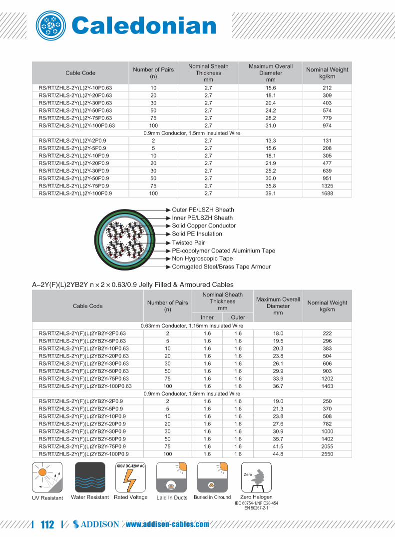
112 www.addison-cables.com
Cable Code Number of Pairs(n)
Nominal Sheath Thickness
mm
Maximum Overall Diameter
mm
Nominal Weightkg/km
RS/RT/ZHLS-2Y(L)2Y-10P0.63 10 2.7 15.6 212RS/RT/ZHLS-2Y(L)2Y-20P0.63 20 2.7 18.1 309RS/RT/ZHLS-2Y(L)2Y-30P0.63 30 2.7 20.4 403RS/RT/ZHLS-2Y(L)2Y-50P0.63 50 2.7 24.2 574RS/RT/ZHLS-2Y(L)2Y-75P0.63 75 2.7 28.2 779RS/RT/ZHLS-2Y(L)2Y-100P0.63 100 2.7 31.0 974
0.9mm Conductor, 1.5mm Insulated WireRS/RT/ZHLS-2Y(L)2Y-2P0.9 2 2.7 13.3 131RS/RT/ZHLS-2Y(L)2Y-5P0.9 5 2.7 15.6 208RS/RT/ZHLS-2Y(L)2Y-10P0.9 10 2.7 18.1 305RS/RT/ZHLS-2Y(L)2Y-20P0.9 20 2.7 21.9 477RS/RT/ZHLS-2Y(L)2Y-30P0.9 30 2.7 25.2 639RS/RT/ZHLS-2Y(L)2Y-50P0.9 50 2.7 30.0 951RS/RT/ZHLS-2Y(L)2Y-75P0.9 75 2.7 35.8 1325RS/RT/ZHLS-2Y(L)2Y-100P0.9 100 2.7 39.1 1688
A-2Y(F)(L)2YB2Y n×2×0.63/0.9 Jelly Filled & Armoured Cables
Cable Code Number of Pairs(n)
Nominal Sheath Thickness
mmMaximum Overall
Diametermm
Nominal Weightkg/km
Inner Outer0.63mm Conductor, 1.15mm Insulated Wire
RS/RT/ZHLS-2Y(F)(L)2YB2Y-2P0.63 2 1.6 1.6 18.0 222RS/RT/ZHLS-2Y(F)(L)2YB2Y-5P0.63 5 1.6 1.6 19.5 296RS/RT/ZHLS-2Y(F)(L)2YB2Y-10P0.63 10 1.6 1.6 20.3 383RS/RT/ZHLS-2Y(F)(L)2YB2Y-20P0.63 20 1.6 1.6 23.8 504RS/RT/ZHLS-2Y(F)(L)2YB2Y-30P0.63 30 1.6 1.6 26.1 606RS/RT/ZHLS-2Y(F)(L)2YB2Y-50P0.63 50 1.6 1.6 29.9 903RS/RT/ZHLS-2Y(F)(L)2YB2Y-75P0.63 75 1.6 1.6 33.9 1202RS/RT/ZHLS-2Y(F)(L)2YB2Y-100P0.63 100 1.6 1.6 36.7 1463
0.9mm Conductor, 1.5mm Insulated WireRS/RT/ZHLS-2Y(F)(L)2YB2Y-2P0.9 2 1.6 1.6 19.0 250RS/RT/ZHLS-2Y(F)(L)2YB2Y-5P0.9 5 1.6 1.6 21.3 370RS/RT/ZHLS-2Y(F)(L)2YB2Y-10P0.9 10 1.6 1.6 23.8 508RS/RT/ZHLS-2Y(F)(L)2YB2Y-20P0.9 20 1.6 1.6 27.6 782RS/RT/ZHLS-2Y(F)(L)2YB2Y-30P0.9 30 1.6 1.6 30.9 1000RS/RT/ZHLS-2Y(F)(L)2YB2Y-50P0.9 50 1.6 1.6 35.7 1402RS/RT/ZHLS-2Y(F)(L)2YB2Y-75P0.9 75 1.6 1.6 41.5 2055RS/RT/ZHLS-2Y(F)(L)2YB2Y-100P0.9 100 1.6 1.6 44.8 2550
Solid Copper ConductorSolid PE Insulation
PE-copolymer Coated Aluminium TapeTwisted Pair
Non Hygroscopic Tape
Inner PE/LSZH SheathOuter PE/LSZH Sheath
Corrugated Steel/Brass Tape Armour
UV Resistant Water Resistant Rated Voltage
600V DC/420V AC
Laid In Ducts Zero HalogenIEC 60754-1/NF C20-454
EN 50267-2-1
Zero
Buried in Ciround

113
Caledonian Railway Cableswww.caledonian-cables.co.uk
Scada/Pilot Cables NR/PS/ELP/27220
Applications The telecom cables are suitable for modem based supervisory system
operating in the VF range from 300 to 3000Hz.
Standards NR/PS/ELP/27220 (formerly RT/E/PS/0034) ●
Construction Conductors: Class 1 solid plain copper ●
conductor 0.9 mm nominal diameter to BS 6360,
complies with BS 3573.
Insulation: Solid polyethylene type 03 to ●
BS 6234.
Cabling Element: Two insulated conductors ●
are twisted together to form a pair.
Filling: Petroleum jelly fi lled. ●
Core Wrapping: PETP (Polyethylene Terephthalate) tape. ●
Moisture Barrier: One laminated sheath made of aluminium tape coated with PE-Copolymer on at least one side ●
is applied with longitudinally overlap.
Inner Sheath: Low density polyethylene type 03C to BS 6234. ●
Screen: Aluminium wire screen. ●
Core Wrapping: Water blocking tape. ●
Sheath: Low density polyethylene type 03C to BS 6234. ●
Electrical Characteristics at 20℃ Nominal Conductor Diameter mm 0.9
Maximum Conductor Resistance Ω/km 30.0
Maximum Average Mutual Capacitance @1000Hz (AC) nF/km 71
Maximum Capacitance Unbalance @1000Hz pair to pair pF/500m 275
Mechanical and Thermal Properties Minimum Bending Radius: 10×OD ●
Temperature Range: -25℃ to +85℃ (during operation); -10℃ to +70℃ (during installation) ●
Solid Copper ConductorPE Insulation
PE-copolymer Coated Aluminium TapeTwisted Pair
PETP Tape
Inner PE SheathOuter PE Sheath
Aluminium Wire ScreenPetroleum Jelly Filling
RAILSIG RAILWAY TELECOM CABLES
Telecommunication Cables for Outdoor Plant UK NETWORK RAIL Standard

114 www.addison-cables.com
Dimensions and Weight
Cable Code Number of PairsNominal Sheath
Thicknessmm
Maximum Overall Diameter
mm
Nominal Weightkg/km
0.9mm Conductor, 1.5mm Insulated Wire
RS27220-2Y(F)(L)2YB2Y-10P0.9 10 1.8 25.8 755
RS27220-2Y(F)(L)2YB2Y-20P0.9 20 1.8 27.8 946
RS27220-2Y(F)(L)2YB2Y-30P0.9 30 2.0 31.8 1225
RS27220-2Y(F)(L)2YB2Y-50P0.9 50 2.0 35.8 1643
RS27220-2Y(F)(L)2YB2Y-75P0.9 75 2.2 41.6 2240
RS27220-2Y(F)(L)2YB2Y-100P0.9 100 2.2 46.6 2780
UV Resistant Water Resistant Rated Voltage
600V DC/420V AC
Laid In Ducts Zero HalogenIEC 60754-1/NF C20-454
EN 50267-2-1
Zero

115
Caledonian Railway Cableswww.caledonian-cables.co.uk
Outdoor Single Mode Trackside Fiber Cables NR/PS/TEL/00014
Applications The cables are fibre communications cable designed for use in high traffic
and data rate requirements.
Standards NR/PS/TEL/00014 (formerly RT/E/PS/00014) ●
Construction Fibre: Step Index Singlemode Fibres in ●
accordance with ITU-T recommendation G.652.9/125
μm Fibre @ 1310nm &1550nm.
Fibre Carrier: PE. ●
Central Strength Member: Single continuous ●
non-metallic.
Binding Tape: Polymeric loose tubes fi lled with water blocking material. ●
Inner Sheath: PE (Polyethylene) Type 03C to BS 6234 or LSZH Sheath. ●
Sheath: PE (Polyethylene) Type 03C to BS 6234 or LSZH sheath. ●
Optional Armoured Cables: Corrugated steel tape armoured cables can be offered as an option.
Electrical Characteristics at 20℃ Maximum Attenuation G652
@1310nm dB/km 0.35@1550nm dB/km 0.22
Maximum Chromatic DispersionBetween 1260 and 1360nm ps/(nm/km) 3.5Between 1530 and 1565nm ps/(nm/km) 19
Zero Dispersion Wavelength nm 1310±11Zero Dispersion Slope ps/(nm2.km) 0.09Numerical Aperture 0.14Point discontinuity dB 0.1PMD (individual fi ber) ps/km 0.2Maximum Cutoff Wavelength nm 1260Cladding Diameter um 125±1Core/Cladding Concentricity Error um ≤0.5
Singlemode Optical Fibres
PE Tube
Inner PE/LSZH SheathOuter PE/LSZH Sheath
Non-metallic Central Reinforcement
RAILOPTICS RAILWAY FIBER CABLES
Telecommunication Cables for Outdoor Plant UK NETWORK RAIL Standard

116 www.addison-cables.com
Cladding Non Circularity % ≤1Coating Non Circularity % ≤6Proof Test Level Kpsi (GN/m2) 100 (0.7)Crush Resistance N/cm 300Maximum Laying Tension N From 12 to 72 FO: 2500;144 FO: 3000
Mechanical and Thermal Properties Minimum Bending Radius: 12×OD . ●
Temperature Range: -20℃ to +60℃ (during operation); -10℃ to +60℃ (during installation) ●
Dimensions and Weight Unarmoured Single Mode Trackside Fiber Cables
Cable Code No. of fi bresNominal Cladding
Thicknessμm
Nominal Sheath Thickness
mm
Nominal Overall
Diametermm
Nominal Weightkg/km
Inner OuterRO14-ML-B-9-2×4-F-2Y2Y 8 125 1.6 2.0 12.0 110RO14-ML-B-9-2×6-F-2Y2Y 12 125 1.6 2.0 12.0 110RO14-ML-B-9-4×5-F-2Y2Y 20 125 1.6 2.0 12.0 110RO14-ML-B-9-8×6-F-2Y2Y 48 125 1.6 2.0 12.6 120RO14-ML-B-9-16×6-F-2Y2Y 96 125 1.6 2.0 14.0 150
Steel Tape Armoured Single Mode Trackside Fiber Cables
Cable Code No. of fi bresNominal Cladding
Thicknessμm
Nominal Sheath Thickness
mm
Nominal Overall
Diametermm
Nominal Weightkg/km
Inner OuterRO14-ML-B-9-2×4-F-2Y(STA)2Y 8 125 1.6 2.0 15.0 210RO14-ML-B-9-2×6-F-2Y(STA)2Y 12 125 1.6 2.0 15.0 210RO14-ML-B-9-4×5-F-2Y(STA)2Y 20 125 1.6 2.0 15.0 210RO14-ML-B-9-8×6-F-2Y(STA)2Y 48 125 1.6 2.0 15.5 230RO14-ML-B-9-16×6-F-2Y(STA)2Y 96 125 1.6 2.0 17.0 270
UV Resistant Water Resistant Rated Voltage
600V DC/420V AC
Laid In Ducts
LSZH Sheath
Flame RetardantNF C32-070-2.1(C2)
IEC 60332-1/EN 50265-2-1NF C32-070-2.2(C1)
IEC 60332-3/EN50266
Fire Retardant
PE Sheath
Zero HalogenIEC 60754-1/NF C20-454
EN 50267-2-1
Zero
Zero HalogenIEC 60754-1/NF C20-454
EN 50267-2-1
Zero
Low Smoke EmissionIEC 61034/NFC20-902EN 50268/NF C32-073
EN 50267-2-2/NF C32-074IEC 60754-2/NF C20-453
Low Corrosivity Low Toxicity

117
Caledonian Railway Cableswww.caledonian-cables.co.uk
G7621 Trackside Communications Cables
Applications The cables are designed for installation in trackside bracket runs and for use
in open locations (type1) or in tunnels or underground locations (type2).
Standards LUL Spec G7621 A2 type 1 (for PVC sheath) ●
LUL Spec G7621 A2 type 2 (for LSZH sheath) ●
Construction Conductors: Solid plain copper, 0.63/0.9 mm nominal ●
diameter.
Insulation: Cellular polyethylene. ●
Cabling Element: Two insulated conductors are twisted together to form a pair. ●
Core Wrapping: Non-hygroscopic plastic tape with overlapping. ●
Outer Sheath: PVC/LSZH sheath, coloured violet. ●
Core Identification 1 Pair Cable: Blue/White
3 Pair Cable: Blue/White Orange/White Green/White
Electrical Characteristics at 20℃ Nominal Conductor Diameter mm 0.63 0.9
Maximum Conductor Resistance
Average Value Ω/km 57.5 28
Individual Value Ω/km 59 29
Minimum Insulation Resistance @500 V DC MΩ.km 1500 1500
Maximum Average Mutual Capacitance nF/km 59 59
Maximum Average Capacitance Unbalance
Pair to Pair pF/460m 100 100
Pair to Earth pF/460m 1200 1200
Mechanical and Thermal Properties Minimum Bending Radius: 7.5×OD ●
Temperature Range: -30℃ to +70℃ (during operation); -10℃ +55℃ (during installation) ●
Solid Copper Conductor
Twisted Pair
Cellular PE Insulation
PVC/LSZH Sheath
Non-hygroscopic Tape
RAILSIG RAILWAY TELECOM CABLES
Telecommunication Cables for Outdoor Plant UK LU London Underground Standard

118 www.addison-cables.com
Dimensions and Weight
Cable Code No. of pairs Nominal Thickness of Sheathmm
Nominal Overall Diametermm
Nominal Weightkg/km
0.63mm Conductor, 1.15mm Insulated WireRS7621A2/T1-02YY-1P0.63 1 2.5 7.0 60RS7621A2/T1-02YY-3P0.63 3 2.5 9.0 90
0.9mm Conductor, 1.5mm Insulated WireRS7621A2/T1-02YY-1P0.9 1 2.5 8.0 70RS7621A2/T1-02YY-3P0.9 3 2.5 10.0 120
Flame RetardantNF C32-070-2.1(C2)
IEC 60332-1/EN 50265-2-1
Mineral Oil Resistant
Rated voltage
750V DC/450V AC
Buried in Ciround Laid In Ducts
LSZH Sheath
Flame RetardantNF C32-070-2.1(C2)
IEC 60332-1/EN 50265-2-1NF C32-070-2.2(C1)
IEC 60332-3/EN50266
Fire Retardant
PVC Sheath
Zero HalogenIEC 60754-1/NF C20-454
EN 50267-2-1
Zero
Low Smoke EmissionIEC 61034/NFC20-902EN 50268/NF C32-073
EN 50267-2-2/NF C32-074IEC 60754-2/NF C20-453
Low Corrosivity Low Toxicity

119
Caledonian Railway Cableswww.caledonian-cables.co.uk
G7622 Trackside Communications Cables
Applications The cables are designed for installation in trackside bracket runs and for use
within railway equipment rooms within open locations (type 1) or in subsurface
tunnels and underground locations (type 2).
Standards LUL Spec G7622 A1 type 1 (for PVC sheath) ●
LUL Spec G7622 A1 type 2 (for LSZH ●
sheath)
Construction Conductors: Solid plain copper, 0.63/0.9 ●
mm nominal diameter.
Insulation: Cellular polyethylene. ●
Cabling Element: Four insulated conductors are twisted together to form a quad. ●
Stranding: Conductors are helically stranded in concentric layers. ●
Core Wrapping: Plastic tape (s) with overlapping. ●
Moisture Barrier: One laminated sheath made of aluminium tape (0.15mm thick) coated with PE-Copolymer on at ●
least one side is applied with longitudinally overlap.
Outer Sheath: LSZH sheath, coloured violet. ●
Optional Type 1 Cables: For type 1 cables, additional foil (at least one polyester tape) and PVC sheath are applied over the
LSZH sheath. (VDE Code: A-02Y(L)HY)
Armoured Cables: Corrugated steel tape armour is applied with an overlap over LSZH sheath. An outer LSZH
sheath is applied over the armour. (VDE Code: A-02Y(L)H(SR)H)
Electrical Characteristics at 20℃ Nominal Conductor Diameter mm 0.63 0.9Maximum Conductor Resistance
Average Value Ω/km 57.5 28Individual Value Ω/km 59 29
Minimum Insulation Resistance @500 V DC MΩ.km 1500 1500Maximum Average Mutual Capacitance nF/km 59 59Maximum Average Capacitance Unbalance
Between pairs in same quad pF/460m 50 50
Cellular PE InsulationQuad
Non Hygroscopic TapeSolid Copper ConductorLSZH Sheath
PE-copolymer Coated Aluminium Tape
RAILSIG RAILWAY TELECOM CABLES
Telecommunication Cables for Outdoor Plant UK LU London Underground Standard

120 www.addison-cables.com
Between pairs (centre or in any layer) pF/460m 30 30Between any pairs and earth pF/460m 200 200Between phantom and pairs in same quad pF/460m 300 300
Mechanical and Thermal Properties Minimum Bending Radius: 7.5×OD (unarmoured); 10×OD (armoured) ●
Temperature Range: -40℃ to +70℃ (during operation); -10℃ to +50℃ (during installation) ●
Core Identifi cation Quad colours in centre and even layers
Position of Quad in LayerCentre and Even Layers
Quad Whipping ColoursA Wire B Wire C Wire D Wire
1st Quad (Marker) ORANGE WHITE BLUE GREY WHITE/ORANGEEven Quads RED WHITE VIOLET YELLOW WHITEOdd Quads BROWN WHITE GREEN GREY WHITELast Quad ORANGE WHITE RED GREEN WHITE/ORANGE
Quad colours in odd layers
Position of Quad in LayerOdd Layers
Quad Whipping ColoursA Wire B Wire C Wire D Wire
1st Quad (Marker) ORANGE BLACK BLUE GREY WHITE/ORANGEEven Quads RED BLACK VIOLET YELLOW WHITEOdd Quads BROWN BLACK GREEN GREY WHITELast Quad ORANGE BLACK RED GREEN WHITE/ORANGE
Make-up of cable
Number of Pairs
Number of Quads in centre and successive layers
Centre 1st Layer 2ndLayer 3th Layer 4th Layer 5th Layer 6th Layer8 4 - - - - - -14 1 6 - - - - -20 2 8 - - - - -28 4 10 - - - - -38 1 6 12 - - - -54 3 9 15 - - - -74 1 6 12 18 - - -104 4 10 16 22 - - -160 4 10 16 22 28 - -228 4 10 16 22 28 34 -308 4 10 16 22 28 34 40
Dimensions and Weight G7622 A1 Type 2 Cables
Cable Code No. of pairsMinimum Sheath
Thicknessmm
Nominal Overall Diameter
mm
Nominal Weightkg/km
0.63mm Conductor, 1.0mm Insulated WireRS7622A1/T2-02Y(L)H-8P0.63 8 2.5 14.5 190RS7622A1/T2-02Y(L)H-14P0.63 14 2.5 16.0 240RS7622A1/T2-02Y(L)H-20P0.63 20 2.5 17.5 310RS7622A1/T2-02Y(L)H-28P0.63 28 2.5 19.5 380RS7622A1/T2-02Y(L)H-38P0.63 38 2.5 21.5 470RS7622A1/T2-02Y(L)H-54P0.63 54 2.5 23.5 610RS7622A1/T2-02Y(L)H-74P0.63 74 2.5 25.5 780RS7622A1/T2-02Y(L)H-104P0.63 104 2.5 29.0 1020RS7622A1/T2-02Y(L)H-160P0.63 160 2.5 34.0 1498RS7622A1/T2-02Y(L)H-228P0.63 228 2.5 39.0 1993

121
Caledonian Railway Cableswww.caledonian-cables.co.uk
Cable Code No. of pairsMinimum Sheath
Thicknessmm
Nominal Overall Diameter
mm
Nominal Weightkg/km
RS7622A1/T2-02Y(L)H-308P0.63 308 2.5 43.5 26700.9mm Conductor, 1.5mm Insulated Wire
RS7622A1/T2-02Y(L)H-8P0.9 8 2.5 17.5 280RS7622A1/T2-02Y(L)H-14P0.9 14 2.5 20.0 380RS7622A1/T2-02Y(L)H-20P0.9 20 2.5 22.5 500RS7622A1/T2-02Y(L)H-28P0.9 28 2.5 24.5 630RS7622A1/T2-02Y(L)H-38P0.9 38 2.5 25.5 790RS7622A1/T2-02Y(L)H-54P0.9 54 2.5 29.0 1060RS7622A1/T2-02Y(L)H-74P0.9 74 2.5 32.5 1370RS7622A1/T2-02Y(L)H-108P0.9 108 2.5 37.5 1830
G7622 A1 Type 1 Cables
Cable Code No. of pairs
Minimum Sheath Thickness mm
Nominal Overall Diameter
mm
Nominal Weightkg/km
Inner Outer0.63mm Conductor, 1.0mm Insulated Wire
RS7622A1/T1-02Y(L)HY-8P0.63 8 2.5 3.0 20.5 330RS7622A1/T1-02Y(L)HY-14P0.63 14 2.5 3.0 22.0 390RS7622A1/T1-02Y(L)HY-20P0.63 20 2.5 3.0 23.5 480RS7622A1/T1-02Y(L)HY-28P0.63 28 2.5 3.0 25.5 560RS7622A1/T1-02Y(L)HY-38P0.63 38 2.5 3.0 27.5 660RS7622A1/T1-02Y(L)HY-54P0.63 54 2.5 3.0 29.5 830RS7622A1/T1-02Y(L)HY-74P0.63 74 2.5 3.0 31.5 1010RS7622A1/T1-02Y(L)HY-104P0.63 104 2.5 3.0 35.0 1290
0.9mm Conductor, 1.5mm Insulated WireRS7622A1/T1-02Y(L)HY-8P0.9 8 2.5 3.0 23.5 440RS7622A1/T1-02Y(L)HY-14P0.9 14 2.5 3.0 26.0 550RS7622A1/T1-02Y(L)HY-20P0.9 20 2.5 3.0 28.5 700RS7622A1/T1-02Y(L)HY-28P0.9 28 2.5 3.0 30.5 840RS7622A1/T1-02Y(L)HY-38P0.9 38 2.5 3.0 31.5 1020RS7622A1/T1-02Y(L)HY-54P0.9 54 2.5 3.0 35.0 1310RS7622A1/T1-02Y(L)HY-74P0.9 74 2.5 3.0 38.5 1650RS7622A1/T1-02Y(L)HY-104P0.9 104 2.5 3.0 43.5 2160
Armoured G7622 A1 Type 2 Cables
Cable Code No. of pairs
Minimum Sheath Thickness mm
Nominal Overall Diameter
mm
Nominal Weightkg/km
Inner Outer0.63mm Conductor, 1.0mm Insulated Wire
RS7622A1/T2-02Y(L)H(SR)H-8P0.63 8 1.2 2.5 18.2 430RS7622A1/T2-02Y(L)H(SR)H-14P0.63 14 1.2 2.5 19.0 500RS7622A1/T2-02Y(L)H(SR)H-20P0.63 20 1.2 2.5 21.2 600RS7622A1/T2-02Y(L)H(SR)H-28P0.63 28 1.2 2.5 22.6 690RS7622A1/T2-02Y(L)H(SR)H-38P0.63 38 1.2 2.5 24.2 810RS7622A1/T2-02Y(L)H(SR)H-54P0.63 54 1.2 2.5 26.7 980RS7622A1/T2-02Y(L)H(SR)H-74P0.63 74 1.2 2.5 29.2 1190RS7622A1/T2-02Y(L)H(SR)H-104P0.63 104 1.2 2.5 32.6 1480
Mineral Oil Resistant
Rated voltage
750V DC/450V AC
Buried in Ciround Laid In DuctsFlame Retardant
NF C32-070-2.1(C2)IEC 60332-1/EN 50265-2-1
PVC Sheath
LSZH Sheath
Flame RetardantNF C32-070-2.1(C2)
IEC 60332-1/EN 50265-2-1NF C32-070-2.2(C1)
IEC 60332-3/EN50266
Fire Retardant Zero HalogenIEC 60754-1/NF C20-454
EN 50267-2-1
Zero
Low Smoke EmissionIEC 61034/NFC20-902EN 50268/NF C32-073
EN 50267-2-2/NF C32-074IEC 60754-2/NF C20-453
Low Corrosivity Low Toxicity
RAILSIG RAILWAY TELECOM CABLES
Telecommunication Cables for Outdoor Plant UK LU London Underground Standard

122 www.addison-cables.com
G7623 Trackside Communications Cables
Applications The cables are designed for limited fi re hazard applications for internal use
within stations, buildings and equipment rooms.
Standards LUL Spec G7623 A2 ●
Construction Conductors: Tinned annealed solid copper, 0.5/0.6/0.63 ●
mm nominal diameter. Insulation: LSZH Insulation. ●Cabling Element: Two insulated conductors are twisted ●
together to form a pair.Stranding: Cables are composed of unit stranding. ●Core Wrapping: Non-hygroscopic plastic tape with overlapping. ●Outer Sheath: LSZH sheath. ●
Electrical Characteristics at 20℃ Nominal Conductor Diameter mm 0.5 0.6 0.63Maximum Conductor Resistance Ω/km 98 68 58Minimum Insulation Resistance @500 V DC MΩ.km 120 120 120Maximum Average Mutual Capacitance @1KHz nF/km 80 80 80Maximum Average Capacitance Unbalance @800Hz pair-to-pair 500 500 500Test Voltage AC 1min V 500 500 500
Mechanical and Thermal Properties Minimum Bending Radius: 7.5×OD ●Temperature Range: -30℃ to +70℃ (during operation); -10℃ +55℃ (during installation) ●
Core Identification Colour scheme, unit binder colour and cable make-up according to G7623
Pair Number A Wire B Wire
Pair Size 20 Pair 40 Pair 80 Pair 100 Pair 160 Pair 320 PairNumber of Units
Center 1 2 1 3x1/2 2 11st Layer 6x1/2* 7x1/2 6 52nd Layer 10
1 WHITE BLUE 1 ORANGE ORANGE ORANGE BLUE ORANGE ORANGE2 WHITE ORANGE 2 GREEN ORANGE ORANGE GREEN ORANGE3 WHITE GREEN 3 NATURAL GREEN ORANGE NATURAL4 WHITE BROWN 4 GREEN BROWN NATURAL NATURAL5 WHITE GREY 5 GREY NATURAL NATURAL6 RED BLUE 6 WHITE NATURAL GREEN7 RED ORANGE 7 RED NATURAL ORANGE8 RED GREEN 8 BLACK GREEN NATURAL
Solid Copper Conductor
Twisted Pair
LSZH Insulation
LSZH Sheath
Non-hygroscopic Tape

123
Caledonian Railway Cableswww.caledonian-cables.co.uk
9 RED BROWN 9 YELLOW NATURAL10 RED GREY 10 VIOLET NATURAL11 BLACK BLUE 11 NATURAL12 BLACK ORANGE 12 NATURAL13 BLACK GREEN 13 NATURAL14 BLACK BROWN 14 NATURAL15 BLACK GREY 15 NATURAL16 YELLOW BLUE 16 GREEN17 YELLOW ORANGE18 YELLOW GREEN19 YELLOW BROWN20 YELLOW GREY
*1/2 refers to units of 10 Pairs
Dimensions and Weight
Cable Code No. of pairs Minimum Sheath Thicknessmm
Nominal Overall Diametermm
Nominal Weightkg/km
0.5mm Conductor, 0.82mm Insulated WireRS7623A2-HH-1P0.5 1 1.3 6.0 30RS7623A2-HH-2P0.5 2 1.3 7.0 45RS7623A2-HH-3P0.5 3 1.4 7.0 50RS7623A2-HH-6P0.5 6 1.5 9.0 61RS7623A2-HH-10P0.5 10 1.6 11.0 107RS7623A2-HH-20P0.5 20 1.9 14.0 190RS7623A2-HH-40P0.5 40 1.9 16.0 320RS7623A2-HH-80P0.5 80 2.2 23.0 640RS7623A2-HH-100P0.5 100 2.2 25.0 760RS7623A2-HH-160P0.5 160 2.6 29.0 1150
0.6mm Conductor, 1.12mm Insulated WireRS7623A2-HH-1P0.6 1 1.4 6.0 35RS7623A2-HH-2P0.6 2 1.4 7.0 50RS7623A2-HH-3P0.6 3 1.5 7.0 60RS7623A2-HH-6P0.6 6 1.6 9.0 85RS7623A2-HH-10P0.6 10 1.7 11.0 145RS7623A2-HH-20P0.6 20 2.2 14.0 245RS7623A2-HH-40P0.6 40 2.2 18.0 410RS7623A2-HH-80P0.6 80 2.8 25.0 830RS7623A2-HH-100P0.6 100 2.8 27.0 980RS7623A2-HH-160P0.6 160 3.2 33.0 1450
0.63mm Conductor, 1.15mm Insulated WireRS7623A2-HH-1P0.63 1 1.4 5.5 40RS7623A2-HH-3P0.63 3 1.5 7.3 70RS7623A2-HH-5P0.63 5 1.6 8.5 89RS7623A2-HH-6P0.63 6 1.6 8.9 100RS7623A2-HH-10P0.63 10 1.7 11.1 170RS7623A2-HH-12P0.63 12 1.7 11.6 195RS7623A2-HH-160P0.63 160 3.2 35.0 1595
Mineral Oil Resistant
Rated voltage
750V DC/450V AC
Buried in Ciround Laid In Ducts
Flame RetardantNF C32-070-2.1(C2)
IEC 60332-1/EN 50265-2-1NF C32-070-2.2(C1)
IEC 60332-3/EN50266
Fire Retardant Zero HalogenIEC 60754-1/NF C20-454
EN 50267-2-1
Zero
Low Smoke EmissionIEC 61034/NFC20-902EN 50268/NF C32-073
EN 50267-2-2/NF C32-074IEC 60754-2/NF C20-453
Low Corrosivity Low Toxicity
RAILSIG RAILWAY TELECOM CABLES
Telecommunication Cables for Outdoor Plant UK LU London Underground Standard

124 www.addison-cables.com
MD4 Medium Distance Trackside Telecom Cables
Applications The cables are designed for long distance of over 10km telecommunications
alongside railway lines.
Standards SNCF CT 2328 (Main cables) /SNCT CT 2329 (Branch cables) ●
Construction CT2328 Type (Main Cables)
Conductors : So l id copper, ●
0.8mm nominal diameter
Insu la t ion : Co loured so l id ●
polyethylene.
Cabling Element: Four conductors are twisted together to form a quad. ●
Possible Harness: Aluminium screen. ●
Filling: Petroleum jelly. ●
Screen: PE-copolymer coated aluminium tape. ●
Drain Wire: Tinned drain wire. ●
Inner Sheath: Low density polyethylene. ●
Screen: One corrugated copper tape. ●
Intermediate Sheath: Low density polyethylene. ●
Armour: Two helically applied steel tapes. ●
Outer Sheath: Low density polyethylene. ●
Optional CT2329 Type (Branch Cables): For CT 2329 type, the cables have PE inner sheath, double corrugated steel tapes
armour and PE outer sheath, without aluminium tape screen & copper tape.
Electrical Characteristics at 20℃ Nominal Conductor Diameter mm 0.8Maximum Conductor Resistance (DC) Ω/km 73.4Minimum Insulation Resistance @500 V DC (3mins) MΩ.km 15000Mutual Capacitance @800Hz nF/km 51Average Capacitance Unbalance
Main CablesIn quad pF/1450 m 50Between quads pF/1450 m 30
Solid Copper ConductorPE InsulationOptional Aluminium ScreenPE Coated Al Tape Screen + Tinned Drain WireInner PE SheathCorrugated Copper TapeIntermediate PE Sheath
Outer PE SheathDouble Steel Tapes

125
Caledonian Railway Cableswww.caledonian-cables.co.uk
Real-ground pF/1450 m 200Branch Cables
In quad pF/1450 m 100Between quads pF/1450 m 100Real-ground pF/1450 m 700
Maximum Attenuation @1MHz dB/km 15.9Maximum Reduction Factor for Main Cables @100V/km 50Hz
14 quads 0.321 quads 0.228 quads 0.18
Dielectric Strength (DC voltage 1min)Conductor to Conductor V 1500Conductor to Screen V 3000
Mechanical and Thermal Properties Bending Radius: 10×OD ●
Temperature Range: -40℃ to +60℃ (during operation); -10℃ +60℃ (during installation) ●
Dimensions and Weight CT2328 (Main cable)
Cable Code No. of QuadsNominal Sheath Thickness
mmNominal Overall
Diametermm
Nominal Weightkg/kmInner Interm. Outer
0.8mm Conductor, 1.27mm Insulated WireRS2328-2Y2Y(K)2YB2Y-14Q0.8 14 1.2 1.1 2.2 29.2 1332RS2328-2Y2Y(K)2YB2Y-21Q0.8 21 1.3 1.3 2.5 31.3 1655RS2328-2Y2Y(K)2YB2Y-28Q0.8 28 1.3 1.3 2.5 35.5 2013
CT2328 (Main cables with screened quads)
Cable Code No. of QuadsNominal Sheath Thickness
mmNominal Overall
Diametermm
Nominal Weightkg/kmInner Interm. Outer
0.8mm Conductor, 1.27mm Insulated WireRS2328-2Y(L)2Y(K)2YB2Y-(14+7)Q0.8 14+7screen Quads 1.3 1.3 2.5 32.7 1765RS2328-2Y(L)2Y(K)2YB2Y-(18+3)Q0.8 18+3screen Quads 1.3 1.3 2.5 32.9 1783
CT2329 (Branch cable)
Cable Code No. of QuadsNominal Sheath Thickness
mmNominal Overall
Diametermm
Nominal Weightkg/km
Inner Outer0.8mm Conductor, 1.4mm Insulated Wire
RS2329-2Y2YB2Y-4Q0.8 4 1.0 1.7 16.4 339RS2329-2Y2YB2Y-8Q0.8 8 1.2 1.8 18.8 477RS2329-2Y2YB2Y-14Q0.8 14 1.2 2.2 22.3 686
UV Resistant Water Resistant Rated voltage
750V DC/450V AC
Laid in Channel Buried in Ciround Zero HalogenIEC 60754-1/NF C20-454
EN 50267-2-1
Zero
RAILOPTICS RAILWAY FIBER CABLES
Telecommunication Cables for Outdoor Plant France RATP Railway Standard

126 www.addison-cables.com
ST2513/CT2243 Outdoor Single Mode Unarmoured Trackside Optical Fiber Cables
Applications The cables are designed for long distance telecom links on optical fibres
along railway tracks. The cables are suitable for pulled through ducts or laid in
channels.
Standards SNCF ST 2513-99 ●
Construction Fibres: Singlemode optical fibres G652 ●
coloured (6 or 12 per tube).
Tube: PBT polyester tubes From 12 to 72 ●
OFs: 1 to 6 tubes; 144 OFs: 12 tubes.
Central Strength Member: Non-metallic central reinforcement (FRP). ●
Filling: Petroleum jelly + water-swelling yarns. ●
Reinforcement: Water-swelling aramid fi bres. ●
Sheath: PE sheath. ●
Electrical Characteristics at 20℃ Maximum Attenuation G652
@1310nm dB/km 0.35@1550nm dB/km 0.22
Maximum Chromatic DispersionBetween 1260 and 1360nm ps/(nm/km) 3.5Between 1530 and 1565nm ps/(nm/km) 19
Zero Dispersion Wavelength nm 1310±11Zero Dispersion Slope ps/(nm2.km) 0.09Numerical Aperture 0.14Point discontinuity dB 0.1PMD (individual fi ber) ps/km 0.2Maximum Cutoff Wavelength nm 1260Cladding Diameter um 125±1Core/Cladding Concentricity Error um ≤0.5Cladding Non Circularity % ≤1Coating Non Circularity % ≤6Proof Test Level Kpsi (GN/m2) 100 (0.7)Crush Resistance N/cm 300Maximum Laying Tension N From 12 to 72 FO: 2500;144 FO: 3000
Singlemode Optical Fibres
PBT Polyester Tube
Water-swelling Aramid Fibres
Outer PE Sheath
Petroleum Jelly + Water-swelling Yarns
Non-metallic Central Reinforcement

127
Caledonian Railway Cableswww.caledonian-cables.co.uk
Mechanical and Thermal Properties Minimum Bending Radius: from 12 to 72 FO: 230mm; 144 FO: 340mm. ●
Temperature Range: -30℃ to +60℃ (during operation); -10℃ +60℃ (during installation) ●
Dimensions and Weight
Cable Code No. of fi bres No of Tubes x No of Fibers/Tube
Nominal Sheath Thickness
mm
Nominal Overall Diameter
mm
Nominal Weightkg/km
RO2513-ML-B-9-1×12-F-2Y 12 1 tubes of 12 OF 1.5 11.6 112
RO2513-ML-B-9-3×12-F-2Y 36 3 tubes of 12 OF 1.5 11.6 112
RO2513-ML-B-9-6×6-F-2Y 36 6 tubes of 6 OF 1.5 11.6 112
RO2513-ML-B-9-6×12-F-2Y 72 6 tubes of 12 OF 1.5 11.6 112
RO2513-ML-B-9-12×12-F-2Y 144 12 tubes of 12 OF 1.5 17.0 225
UV Resistant Water Resistant Laid In Ducts Zero HalogenIEC 60754-1/NF C20-454
EN 50267-2-1
Zero
Laid in Channel
RAILSIG RAILWAY TELECOM CABLES
Telecommunication Cables for Outdoor Plant France RATP Railway Standard

128 www.addison-cables.com
CT2242 Outdoor Single Mode Armoured Trackside Optical Fiber Cables
Applications The cables are designed for long distance telecom links on optical fi bres along
railway tracks. The cables are suitable for installation directly in channels or buried.
Standards SNCF CT 2242.6.1 ●
Construction Fibres: Singlemode optical fibres G652 ●
coloured (6 or 12 per tube).Central Strength Member: Non-metallic ●
central reinforcement (FRP).Tube: PBT polyester tubes containing ●
fi bres.Filling: Petroleum jelly with water-swelling yarns to provide longitudinal watertightness. ●Inner Sheath: Low density polyethylene. ●Armour: 0.25mm thick corrugated steel tape armour. ●Outer Sheath: Low density polyethylene. ●
Electrical Characteristics at 20℃ Maximum Attenuation G652
@1310nm dB/km 0.35@1550nm dB/km 0.22
Maximum Chromatic DispersionBetween 1260 and 1360nm ps/(nm/km) 3.5Between 1530 and 1565nm ps/(nm/km) 19
Zero Dispersion Wavelength nm 1310±11Zero Dispersion Slope ps/(nm2.km) 0.09Numerical Aperture 0.14Point discontinuity dB 0.1PMD (individual fi ber) ps/km 0.2Maximum Cutoff Wavelength nm 1260Cladding Diameter um 125±1Core/Cladding Concentricity Error um ≤0.5Cladding Non Circularity % ≤1Coating Non Circularity % ≤6Proof Test Level Kpsi (GN/m2) 100 (0.7)Crush Resistance N/cm 450Maximum Laying Tension N 3000
Singlemode Optical Fibres
PBT Polyester Tube
Corrugated Steel Tape Armour
Outer PE Sheath
Petroleum Jelly + Water-swelling Yarns
Non-metallic Central Reinforcement
Inner PE Sheath

129
Caledonian Railway Cableswww.caledonian-cables.co.uk
Mechanical and Thermal Properties Minimum Bending Radius: 310mm. ●
Temperature Range: -40℃ to +70℃ (during operation); -10℃ +70℃ (during installation) ●
Dimensions and Weight
Cable Code No. of fi bresNominal Sheath
Thicknessmm
Nominal Overall Diameter
mm
Nominal Weightkg/km
RO2242-ML-C-9-Tn×Fn-SR-2Y(STA)2Y 1-36 1.5 14.5 260RO2242-ML-C-9-Tn×Fn-SR-2Y(STA)2Y 48-72 1.5 16.5 300RO2242-ML-C-9-Tn×Fn-SR-2Y(STA)2Y 80-144 1.5 22.0 510
Tn: Number of tubes; Fn: Number of fi bers in a tube
UV Resistant Water Resistant Zero HalogenIEC 60754-1/NF C20-454
EN 50267-2-1
Zero
Laid in Channel Buried in Ciround
RAILOPTICS RAILWAY FIBER CABLES
Telecommunication Cables for Outdoor Plant France RATP Railway Standard

130 www.addison-cables.com
K20 & L120 LSZH Armoured F/FTP Cat6 Cables
Applications The cables are designed for high speed data transmissions, and are suitable
for installations in cable trays or on hooks.
Standards RATP CAT6-K20 (for K20 cable) ●FRANCE TELECOM S31-10/20 & NF C 93.531-6/7 (for L120 cable) ●
Construction Conductors: Class 1 AWG23 sol id copper ●
conductor (for K20 cable); 0.6mm annealed copper conductor (for L120 cable).
Insulation: Solid polyethylene (for K20 cable); ●Foam skin (cellular PE + solid PE) (for L120 cable).
Cabling Element: Two conductors are twisted ●together to form a pair (for K20 cable); Four conductors are twisted together to form a quad (for L120 cable).
Core Wrapping (for L120 cable): Non-hygroscopic ●plastic tape with overlapping.
Individual Screen (for K20 cable): Alu/polyester ●shield on each pair.
Overall Screen: Alu/polyester shield. ●Drain Wire: Tinned copper drain wire, 0.5mm ●
nominal diameter.Inner Sheath (for K20 cable): LSZH. ●Armour (for K20 cable): Galvanized steel braid ●
armour.Outer Sheath: LSZH. ●
Optional Armoured L120 Cables: Tinned copper braid armoured cables can be offered upon request.
Electrical Characteristics at 20℃ Nominal Conductor Diameter mm 0.56 (K20) 0.6 (L120)AWG 23 23Maximum Conductor Resistance Ω/km 146.4 133.2Minimum Insulation Resistance @500 V DC MΩ/km 5000 5000Characteristics Impedance @100MHz Ω 100 120+15Maximum Capacitance Unbalance
Real/earth pF/km 1600 300Maximum Average Attenuation
@1MHz dB/100m 2.0 2.0@4MHz dB/100m 3.8 3.8@10MHz dB/100m 6.0 6.0@16MHz dB/100m 7.6 7.6@25MHz dB/100m 9.5 9.5
Solid Copper ConductorPE Insulation
Drain WireInner LSZH Sheath
Outer LSZH Sheath
Galvanized Steel Braid Armour
Individual Al/Polyester Screen
Overall Al/Polyester Screen
Annealed Copper Conductor
Foam Skin Insulation
Drain Wire
Outer LSZH Sheath
Overall Al/polyester Screen
Star Quad
K20
L120

131
Caledonian Railway Cableswww.caledonian-cables.co.uk
@31.25MHz dB/100m 10.7 [email protected] dB/100m 15.4 15.4@100MHz dB/100m 19.8 19.8@250MHz dB/100m 32.9 32.9
Minimum NEXT Pair to Pair@1MHz dB 77.3 77.3@4MHz dB 68.3 68.3@10MHz dB 62.3 62.3@16MHz dB 59.2 59.2@25MHz dB 56.3 [email protected] dB 54.9 [email protected] dB 50.4 50.4@100MHz dB 47.3 47.3@250MHz dB 41.3 41.3
Minimum ELFEXT Pair to Pair@1MHz dB 68.8 68.8@4MHz dB 56.8 56.8@10MHz dB 48.8 48.8@16MHz dB 44.7 44.7@25MHz dB 40.8 [email protected] dB 38.9 [email protected] dB 32.8 32.8@100MHz dB 28.8 28.8@250MHz dB 20.8 20.8
Mechanical and Thermal Properties Minimum Bending Radius: 12×OD (static); 24×OD (dynamic) ●Temperature Range: -40℃ to +60℃ (during operation); -10℃ +60℃ ●
(during installation)
Dimensions and Weight K20 cables
Cable Code No. of pairs
Nominal Sheath Thicknessmm
Nominal Overall Diameter
mm
Nominal Weightkg/kmInner Outer
0.56mm conductor, 1.45mm Insulated WireRD/K20-F/FTPCat6-2Y(St)H(SWB)H-PIMF-4P0.56 4 1.0 1.0 11.7 156
L120 cables
Cable Code No. of pairsNominal Sheath
Thicknessmm
Nominal Overall Diameter
mm
Nominal Weightkg/km
0.6mm conductor, 1.34mm Insulated WireRD/L120-F/FTPCat6-02YHH-4P0.6 4(2Q) 1.8 8.5 x 6* 60RD/L120-F/FTPCat6-02YHH-8P0.6 8(2 x 4p) 1.8 18 x 6** 120RD/L120-F/FTPCat6-02YHH-12P0.6 12(3 x 4p) 1.8 16 235RD/L120-F/FTPCat6-02YHH-32P0.6 32(4 x 4Q) 1.8 19 360RD/L120-F/FTPCat6-02YHH-64P0.6 64(8 x 4Q) 1.8 30 675RD/L120-F/FTPCat6-02YHH-128P0.6 128(4SU x 4Q) 1.8 40 1250
SU=super unit. * For 4 pair L120 cable, 8 insulated wires form 2 quads and the cable is fl at.** For 8 pair L120 cable, two fl at quads are assembled under a common LSH sheath.
Impact Resistant Mineral Oil Resistant
Acid&AlkalineResistant
Flame RetardantNF C32-070-2.1(C2)
IEC 60332-1/EN 50265-2-1NF C32-070-2.2(C1)
IEC 60332-3/EN50266
Fire Retardant Zero HalogenIEC 60754-1/NF C20-454
EN 50267-2-1
Zero
Low Smoke EmissionIEC 61034/NFC20-902EN 50268/NF C32-073
EN 50267-2-2/NF C32-074IEC 60754-2/NF C20-453
Low Corrosivity Low ToxicityLaid in CableTrays/on Hooks
RAILDATA RAILWAY DATA CABLES
Telecommunication Cables for Indoor Plant France RATP Railway Standard

132 www.addison-cables.com
K209B LSZH Armoured Optical Fiber Cables
Applications The cables are designed for long distance telecommunication and using
optical fibres in urban railways infrastructure. These low smoke halogen-free cables are laid on hooks, pulled through ducts or cable trays.
Standards RATP K209B or RATP K209A ●
Construction Compact Tube: 6 or 12 singlemode optical fibres ●
G652 or multimode fi bers assembled under thermoplastic “peelable” skin. Tube diameter: 1mm.
Filling: Water-swelling yarns. ●Tube: Thermoplastic. ●Peripheral Strength Member: Water-swelling glass yarns. ●Armour: Corrugated steel tape armour 25/100. ●Sheath: LSZH. ●
Optional K209A Type: For K209A type, the cables have loose tubes with 6-12 fi bers, steel wire strand as central strength
member, glass yarn reinforced, incorporating a corrugated steel tape armour and an outer UV stabilized LSZH jacket.
Electrical Characteristics at 20℃ Optical & Geometrical Properties for Single Mode Fibers
Maximum Attenuation G652@1310nm dB/km 0.35@1550nm dB/km 0.22
Maximum Chromatic DispersionBetween 1260 and 1360nm ps/(nm/km) 3.5Between 1530 and 1565nm ps/(nm/km) 19
Zero Dispersion Wavelength nm 1310±11Zero Dispersion Slope ps/(nm2.km) 0.09Numerical Aperture 0.14Point discontinuity dB 0.1PMD (individual fi ber) ps/km 0.2Maximum Cutoff Wavelength nm 1260Cladding Diameter um 125±1Core/Cladding Concentricity Error um ≤0.5Cladding Non Circularity % ≤1Coating Non Circularity % ≤6Proof Test Level Kpsi (GN/m2) 100 (0.7)Crush Resistance N/cm 300Maximum Laying Tension N 3000
Optical Fibres
Thermoplastic Tube
Water-swelling Glass Yarns
Outer LSZH Sheath
Corrugated Steel Tape Armour
Compact Tube

133
Caledonian Railway Cableswww.caledonian-cables.co.uk
Optical & Geometrical Properties for Multimode Fibers50/125 62.5/125
Maximum Attenuation@850nm dB/km ≤2.5 ≤3.0@1300nm dB/km ≤0.7 ≤0.8
Maximum Chromatic Dispersion@850nm MHz*km ≥500 ≥200@1300nm MHz*km ≥800 ≥500
Zero Dispersion Wavelength nm 1310 1310Numerical Aperture - 0.20±0.015 0.275±0.015Core Diameter um 50±3 62.5±3Cladding Diameter um 125±2 125±2Core/Cladding Concentricity Error(Offset) um ≤1.5 ≤1.5Coating-Clad Concentricity Error(Offset) um ≤8 ≤8Core Non-Circularity % ≤6 ≤6Cladding Non-Circularity % ≤2 1 ≤2 1Coating Diameter um 245±10 245±10Proof-Test Level Kpsi (GN/m2) 100 (0.7) 100 (0.7)
Mechanical and Thermal Properties Bending Radius: 20×OD ●Temperature Range: -40℃ to +60℃ (during operation); -10℃ +60℃ (during installation) ●
Dimensions and Weight K209A
Cable Code No. of fi bres Distribution
Nominal Sheath
Thicknessmm
Nominal Overall
Diametermm
Nominal Weightkg/km
RO/K209A-ML-C-9-TnxFn-SR-(STA)H 1-36 6 fi bre per tubes 1.8 12 190RO/K209A-ML-C-9-TnxFn-SR-(STA)H 42-72 6/12 fi bre per tubes 1.8 13.5 230
Tn: Number of tubes; Fn: Number of fi bers in a tube
K209B
Cable Code No. of fi bres
No of Tubes x No of Fibers/Tube
Nominal Sheath Thickness
mm
Nominal Overall Diameter
mm
Nominal Weightkg/km
Singlemode Fibres From 6 to 36 OF – G652RO/K209B-ML-C-9-2x6-F-(STA)H 12 2 tubes of 6 OF 1.8 13 112RO/K209B-ML-C-9-4x6-F-(STA)H 24 4 tubes of 6 OF 1.8 13 112RO/K209B-ML-C-9-6x6-F-(STA)H 36 6 tubes of 6 OF 1.8 13 112
Singlemode Fibres From 48 to 72 OF – G652RO/K209B-ML-C-9-8x6-F-(STA)H 48 8 tubes of 6 OF 2.5 15.5 230RO/K209B-ML-C-9-6x12-F-(STA)H 72 6 tubes of 12 OF 2.8 15.5 230
Multimode Fibres From 6 to 36 OF – 50/125RO/K209B-ML-C-9-1x6-F-(STA)H 6 1 tubes of 6 OF 1.8 13 112RO/K209B-ML-C-9-2x6-F-(STA)H 12 2 tubes of 6 OF 1.8 13 112
Impact Resistant Mineral Oil Resistant
Acid&AlkalineResistant
Flame RetardantNF C32-070-2.1(C2)
IEC 60332-1/EN 50265-2-1NF C32-070-2.2(C1)
IEC 60332-3/EN50266
Fire Retardant Zero HalogenIEC 60754-1/NF C20-454
EN 50267-2-1
Zero
Low Smoke EmissionIEC 61034/NFC20-902EN 50268/NF C32-073
EN 50267-2-2/NF C32-074IEC 60754-2/NF C20-453
Low Corrosivity Low Toxicity
Laid in CableTrays/on Hooks
RAILOPTICS RAILWAY FIBER CABLES
Telecommunication Cables for Indoor Plant France RATP Railway Standard

134 www.addison-cables.com
K26 LSZH 50/75Ω Coaxial Cables
Applications The 50Ω cables are HF transmission coaxial cables for GSM antennas, and
the 75Ω cables are HF transmission coaxial cables for cameras (type KX6), and
video surveillance (type 11 RTC). The Halogen-free cables are suitable for laid on
hooks, and pulled through walls or through technical ducts.
Standards RATP K26 ●
Fire Performance: NF C 32070.2.2 ●
Construction Inner Conductors: ●
50Ω cables:
Flexible Type (F)- solid copper coated aluminium (for 1/4″ , 3/8″ &1/2″ F conductor); red copper tube (for
7/8″ and 1'1/4 F conductor); corrugated red copper tube (for 1'5/8 F conductor).
Super Flexible Type (SF) - solid copper coated aluminium (for 3/8″ & 1/2″ SFconductor); helical corrugated
copper tube (for 7/8” SF conductor); copper wire (for 1/4″ SFconductor).
Extra Flexible (XF) – copper wire (for 1/4" XF conductor); solid copper coated aluminium (for 3/8" XF
conductor).
75Ω cables: solid red copper (for type 11 RTC) or red copper tube (for type KX6).
Dielectric: Cellular PE or natural PE (only for KX6 type). ●
Outer Conductor: ●
50Ω cables: corrugated copper tube.
75Ω cables: copper braid.
Outer sheath: LSZH. ●
Electrical Characteristics at 20℃ 50Ω Cables
Type of Cable inch 1/4"F 3/8"F 1/2"F 7/8"F 1'1/4F 1'5/8FImpedance Ω 50 50 50 50 50 50Attenuation
@10MHz dB/100m 1.25 1.46 0.65 0.34 0.25 0.2@150MHz dB/100m 4.99 4.22 2.61 1.45 1.02 0.85@200MHz dB/100m 5.8 4.90 3.04 1.69 1.19 1.00@450MHz dB/100m 8.8 7.51 4.66 2.61 1.86 1.57@900MHz dB/100m 12.8 11.1 6.78 3.81 2.75 2.34@1000MHz dB/100m 13.5 11.6 7.18 4.04 2.93 2.49
Inner Conductor
Outer Conductor
LSZH Sheath
Cellular PE/Natural PE Insulation

135
Caledonian Railway Cableswww.caledonian-cables.co.uk
@1500MHz dB/100m 17.0 14.4 8.99 5.08 3.72 3.17@1700MHz dB/100m 18.3 15.5 9.64 5.45 4.01 3.42
Average Power Rating @10MHz KW 5.79 7.23 13 28.0 41 57@150MHz KW 1.45 1.81 3.2 7.0 11 13@200MHz KW 1.25 1.56 2.75 6.0 9.0 11@450MHz KW 0.818 1.02 1.8 3.88 5.5 6.9@900MHz KW 0.566 0.70 1.25 2.65 3.83 4.49@1000MHz KW 0.533 0.663 1.18 2.50 3.60 4.20@1500MHz KW 0.426 0.53 0.947 1.99 2.82 3.22@1700MHz KW 0.398 0.494 0.884 1.85 2.61 2.96
Velocity of Propagation % 85 88 88 88 88 88
Type of Cable inch 1/4"SF 3/8"SF 1/2"SF 7/8"SF 1/4"XF 3/8"XFImpedance Ω 50 50 50 50 50 50Attenuation
@10MHz dB/100m 1.71 1.3 0.83 0.39 2.31 1.098@150MHz dB/100m 6.89 4.89 3.87 1.59 7.44 4.38@200MHz dB/100m 8.01 5.59 4.53 1.85 8.54 5.098@450MHz dB/100m 12.31 8.49 7.09 2.85 14.3 7.83@900MHz dB/100m 17.92 12.66 10.45 4.15 20.5 11.4@1000MHz dB/100m 18.98 13.5 11.09 4.4 21.83 12.1@1500MHz dB/100m 23.78 17.43 13.98 5.52 27.13 15.1@1700MHz dB/100m 25.51 18.91 15.03 5.92 29.5 16.2
Average Power Rating @10MHz KW 2.8 6.0 8.4 21.5 3.8 7.02@150MHz KW 0.7 1.52 2.1 5.4 0.9 1.76@200MHz KW 0.6 1.31 1.81 4.6 0.8 1.51@450MHz KW 0.39 0.86 1.18 3.0 0.51 0.99@900MHz KW 0.272 0.593 0.815 2.07 0.37 0.68@1000MHz KW 0.257 0.56 0.77 1.95 0.34 0.64@1500MHz KW 0.206 0.449 0.616 1.55 0.26 0.51@1700MHz KW 0.192 0.42 0.575 1.45 0.24 0.48
Velocity of Propagation % 83 81 82 88 84 85
75Ω CablesType of Cable inch 11 RTC KX6Impedance Ω 75 75
@50MHz dB/100m 2.5 8.13@100MHz dB/100m 3.6 11.73@150MHz dB/100m 4.6 14.53@200MHz dB/100m 5.4 16.92@500MHz dB/100m 8.5 27.0@800MHz dB/100m 10.5 35.1@1000MHz dB/100m 12.2 40.02
Velocity of Propagation % 87 66
Mechanical and Thermal Properties Minimum Bending Radius: 7.5×OD ●
Temperature Range: 50Ω cables: -40℃ to +85℃ (during operation); -20℃ to +60℃ (during installation); ●
75Ω cables: -20℃ to +85℃ (during operation); -10℃ to +60℃ (during installation).
RAILCOX RAILWAY COAXIAL CABLES
Telecommunication Cables for Indoor Plant France RATP Railway Standard

136 www.addison-cables.com
Dimensions and Weight 50Ω Cables
Cable CodeNominal Inner
Conductor Diametermm
Nominal Outer Conductor Diameter
mm
Nominal Overall Diameter
mm
Nominal Weightkg/km
1/4″ F Cable TypeRS/K26-F-HCAAYZ-50-6(1/4") 2.5 7.6 9.5 145
3/8″ F Cable TypeRS/K26-F-HCAAYZ-50-8(3/8") 3.3 9.5 11.5 204
1/2″ F Cable TypeRS/K26-F-HCAAYZ-50-12(1/2") 4.8 13.7 16.0 248
7/8″ F Cable TypeRS/K26-F-HCTAYZ-50-22(7/8") 9.0 24.8 27.75 575
1'1/4 F Cable TypeRS/K26-F-HCTAYZ-50-32(1'1/4) 13.0 35.7 39.5 1133
1'5/8 F Cable TypeRS/K26-F-HHTAYZ-50-42(1'5/8) 17.3 46.2 50.0 1631
1/4″ SF Cable TypeRS/K26-HRYZ-50-5(1/4" SF) 1.9 6.4 7.95 99
3/8″ SF Cable TypeRS/K26-HRCAYZ-50-7(3/8" SF) 2.8 9.6 11.15 159
1/2″ SF Cable TypeRS/K26-HRCAYZ-50-9(1/2" SF) 3.6 12.1 13.65 201
7/8″ SF Cable TypeRS/K26-HRCTYZ-50-22(7/8" SF) 9.4 25.0 27.5 550
1/4″ XF Cable TypeRS/K26-HRYZ-50-5(1/4" XF) 5.75 5.6 6.85 69
3/8″ XF Cable TypeRS/K26-HRCAYZ-50-7(3/8" XF) 2.76 8.0 10.1 111
*F = fl exible, SF = super fl exible, XF = extrafl exible
75Ω Cables
Cable CodeNominal Inner
Conductor Diametermm
Nominal Outer Conductor Diameter
mm
Nominal Overall Diameter
mm
Nominal Weightkg/km
11 RTC Cable TypeRS/K26-11RTC-BC80-H 1.7 7.85 10.3 115
KX6 Cable TypeRS/K26-KX6-BC80-H 0.6 4.85 7.2 66
Flame RetardantNF C32-070-2.1(C2)
IEC 60332-1/EN 50265-2-1NF C32-070-2.2(C1)
IEC 60332-3/EN50266
Fire Retardant Zero HalogenIEC 60754-1/NF C20-454
EN 50267-2-1
Zero
Low Smoke EmissionIEC 61034/NFC20-902EN 50268/NF C32-073
EN 50267-2-2/NF C32-074IEC 60754-2/NF C20-453
Low Corrosivity Low Toxicity
Impact Resistant Mineral Oil Resistant
Acid&AlkalineResistant
Laid in Ducts/on Hooks

137
Caledonian Railway Cableswww.caledonian-cables.co.uk
RAILFEEDER RAILWAY POWER & CONTROL CABLES
RAILFEEDER Railway Power & Control Cables

138 www.addison-cables.com
K25 Track Feeder Cables to NF F 55-625
Applications The cables are designed for fixed power or lighting installations in rail
transport.
Standards NF F 55-625 ●
UNE 21123 ●
Construction Conductors: Stranded bare copper conductor, ●
1.5mm² to IEC 60228 class 2.
Insulation: XLPE. ●
Filler & Inner Covering: LSZH. ●
Armour: Galvanized steel tapes. ●
Outer Sheath: LSZH, antitermite, coloured black. ●
Electrical Characteristics at 20℃ Nominal Conductor Cross Section mm² 1.5Maximum DC Conductor Resistance Ω/km 12.2Minimum Insulation resistance @500VDC MΩ.km 1500Voltage Rating KV 0.6/1(0.45/0.75 optional)
Mechanical and Thermal Properties Miniumum Bending Radius: 10×OD ●
Operating Temperatures: -20℃ to +60℃ (during operation); -10℃ to +60℃ (during installation) ●
Core Identification Colours coding: Black, Light blue, Brown, Green/Yellow, Black
XLPE InsulationStranded Bare Copper Conductor
Galvanized Steel TapeFiller + Inner LSZH Sheath
Outer LSZH Sheath

139
Caledonian Railway Cableswww.caledonian-cables.co.uk
Dimensions and Weight
Cable Code
No. of cores& Nominal Conductor Cross Sectional Area
No.×mm²
No. & Nominal Diameter of
StrandsNo/mm
Minimum Overall
Diametermm
Maximum Overall
Diametermm
Nominal Weightkg/km
RF/K25-RZ1F3Z1-U(AS)-0.6/1KV-2G1.5 2 x 1.5 7/0.53 8.0 12.0 100RF/K25-RZ1F3Z1-U(AS)-0.6/1KV-4G1.5 4 x 1.5 7/0.53 12.5 14.5 300RF/K25-RZ1F3Z1-U(AS)-0.6/1KV-12G1.5 12 x 1.5 7/0.53 18.0 20.0 590RF/K25-RZ1F3Z1-U(AS)-0.6/1KV-21G1.5 21 x 1.5 7/0.53 22.0 24.0 830
U is changed to K if the stranding class is changed from class 2 to class 5
Flame RetardantNF C32-070-2.1(C2)
IEC 60332-1/EN 50265-2-1NF C32-070-2.2(C1)
IEC 60332-3/EN50266
Fire Retardant Zero HalogenIEC 60754-1/NF C20-454
EN 50267-2-1
Zero
Low Smoke EmissionIEC 61034/NFC20-902EN 50268/NF C32-073
EN 50267-2-2/NF C32-074IEC 60754-2/NF C20-453
Low Corrosivity Low Toxicity
RAILFEEDER RAILWAY POWER & CONTROL CABLES
France RATP Railway Standard

140 www.addison-cables.com
450/750V Track Feeder Cables to RT/E/S/21101
Applications The cables can provide the 450/750 volt DC supply from Traction Substations
and Track Paralleling Huts to conductor rails, negative cable connections and
where appropriate bonding.
Standards NR/PS/ELP/21101 (formerly RT/E/S/21101) ●
BS 638 Part 4 ●
UNE 21027 ●
Construction Conductors : Class 5 s t randed ●
aluminium or tinned copper to BS EN
60228: 2005 (previously BS 6360).
Core Wrapping: PETP (Polyethylene ●
Terephthalate).
Sheath: CSP(Chlorosulfonated Polyethylene) type RS4 to BS 6899. ●
H.O.F.R. heat resistant, oil resistant and fl ame retardant. ●
Electrical Characteristics at 20℃ Nominal Conductor Cross Section mm² 161 500 630 150 240 500 800 1000Conductor Material copper AluminiumMaximum DC Conductor Resistance Ω/km 0.109 0.0369 0.0286 0.206 0.125 0.0605 0.0307 0.0291Assigned Continuous Current Rating A 550 1200 1500 430 550 800 1200 1500Voltage Rating KV 0.45/0.75
Mechanical and Thermal Properties Miniumum Bending Radius: 10×OD (Aluminium Conductor); 8×OD (Copper Conductor) ●
Operating Temperatures: -25℃ to +85℃ (during operation); -10℃ to +70℃ (during installation) ●
Stranded Aluminium/Tinned Copper Conductor
CSP Sheath
PETP

141
Caledonian Railway Cableswww.caledonian-cables.co.uk
Dimensions and Weight
Cable Code
No. of cores& Nominal Conductor
Cross Sectional Area
No.×mm²
No. & Nominal
Diameter of StrandsNo/mm
Nominal Sheath
Thicknessmm
Nominal Overall
Diametermm
Nominal Weightkg/km
Polarity/Gland Size
Copper ConductorRF21101-H01N2-D-450/750V-1G161CU 1×161 820/0.5 4.0 25.9 2050 negative/32RF21101-H01N2-D-450/750V-1G500CU 1×500 1769/0.6 4.0 42.3 5582 negative/50RF21101-H01N2-D-450/750V-1G630CU 1×630 2257/0.6 4.0 45.9 6879 positive/63S
Aluminium ConductorRF21101-H01N2-D-450/750V-1G150AL 1×150 756/0.5 4.0 20.5 581 negative/25RF21101-H01N2-D-450/750V-1G240AL 1×240 1221/0.5 4.0 29.6 1171 negative/40RF21101-H01N2-D-450/750V-1G500AL 1×500 1769/0.6 4.0 42.0 2361 positive/50RF21101-H01N2-D-450/750V-1G800AL 1×800 2825/0.6 4.0 50.2 3498 negative/63SRF21101-H01N2-D-450/750V-1G1000AL 1×1000 3531/0.6 4.0 55.0 4226 positive/63
Impact Resistant Highly Flexible Oil Resistant Weather Resistant Laid In Ducts
RAILFEEDER RAILWAY POWER & CONTROL CABLES
UK NETWORK RAIL Standard

142 www.addison-cables.com
450/750V LSZH Track Feeder Cables to EME-SP-14-025/SE908
Applications The cables can provide the 450/750 volt DC supply from Traction Substations
and Track Paralleling Huts to conductor rails, negative cable connections and
where appropriate bonding.
Standards EME SP 14 025 (replaced by LUL 1-108 and Metronet MR SE908) ●UNE 21123 ●
Construction Conductors: Stranded tinned copper conductors ●
to IEC 60228 class 2 or 5.Insulation: EPR. ●Sheath: LSZH sheathed with yellow stripe. ●
Electrical Characteristics at 20℃ Nominal Conductor Cross Section mm² 500 935Maximum DC Conductor Resistance Ω/km 0.0361 0.0194Voltage Rating KV 0.45/0.75
Mechanical and Thermal Properties Miniumum Bending Radius: 8×OD ●
Operating Temperatures: -25℃ to +85℃ (during operation); -10℃ to +70℃ (during installation) ●
Dimensions and Weight
Cable Code
No. of cores& Nominal Conductor Cross Sectional Area
No.×mm²
No. & Nominal
Diameter of StrandsNo/mm
Nominal Sheath
Thicknessmm
Nominal Overall
Diametermm
Nominal Weightkg/km
RF14025-DZ1-U(AS)-450/750V-1G500 1×500 91/2.65 8.5 54.0 7185RF14025-DZ1-U(AS)-450/750V-1G935 1×935 169/2.65 9.5 65.0 11749
U is changed to K if the stranding class is changed from class 2 to class 5
Flexible Tinned Copper Conductor
LSZH Sheath
EPR Insulation
Flame RetardantNF C32-070-2.1(C2)
IEC 60332-1/EN 50265-2-1NF C32-070-2.2(C1)
IEC 60332-3/EN50266
Fire Retardant Zero HalogenIEC 60754-1/NF C20-454
EN 50267-2-1
Zero
Low Smoke EmissionIEC 61034/NFC20-902EN 50268/NF C32-073
EN 50267-2-2/NF C32-074IEC 60754-2/NF C20-453
Low Corrosivity Low Toxicity

143
Caledonian Railway Cableswww.caledonian-cables.co.uk
450/750V LSZH Single Core Conduit Wires to EME-SP-14-026
Applications The cables are designed for fixed power or lighting installations in rail
transport.
Standards EME SP 14 026 (LUL version of BS 7211) ●
UNE 211002 ●
Construction Conductors: Stranded plain copper conductors to IEC ●
60228 class 2 or 5.
Insulation: LSZH. ●
Electrical Characteristics at 20℃ Nominal Conductor Cross Section mm² 1.5 2.5 4.0 6.0 10.0 16.0 25.0 35.0 50.0 70.0
Maximum DC Conductor Resistance Ω/km 12.1 7.41 4.61 3.08 1.83 1.15 0.727 0.524 0.387 0.268
Voltage Rating KV 0.45/0.75
Nominal Conductor Cross Section mm² 95 120 150 185 240 300 400 500 630
Maximum DC Conductor Resistance Ω/km 0.193 0.153 0.124 0.0991 0.0754 0.0601 0.0470 0.0366 0.0283
Voltage Rating KV 0.45/0.75
Mechanical and Thermal Properties Miniumum Bending Radius: 8×OD ●
Operating Temperatures: -25℃ to +85℃ (during operation); -10℃ to +70℃ (during installation) ●
Stranded Copper Conductor
LSZH Insulation
RAILFEEDER RAILWAY POWER & CONTROL CABLES
UK NETWORK RAIL Standard

144 www.addison-cables.com
Dimensions and Weight
Cable Code
No. of cores& Nominal Conductor Cross Sectional Area
No.×mm²
No. & Nominal Diameter of
StrandsNo/mm
Nominal Insulation Thickness
mm
Nominal Overall
Diametermm
Nominal Weightkg/km
RF14026-ES07Z-U(AS)-450/750V-1G1.5 1 x 1.5 7/0.53 0.7 3.0 22RF14026-ES07Z-U(AS)-450/750V-1G2.5 1 x 2.5 7/0.67 0.8 3.6 34RF14026-ES07Z-U(AS)-450/750V-1G4 1 x 4.0 7/0.85 0.8 4.1 50RF14026-ES07Z-U(AS)-450/750V-1G6 1 x 6.0 7/1.04 0.8 4.7 70RF14026-ES07Z-U(AS)-450/750V-1G10 1 x 10.0 7/1.35 1.0 5.8 114RF14026-ES07Z-U(AS)-450/750V-1G16 1 x 16.0 7/1.70 1.0 6.8 175RF14026-ES07Z-U(AS)-450/750V-1G25 1 x 25.0 7/2.14 1.2 8.6 272RF14026-ES07Z-U(AS)-450/750V-1G35 1 x 35.0 19/1.53 1.2 10.2 377RF14026-ES07Z-U(AS)-450/750V-1G50 1 x 50.0 19/1.78 1.4 11.9 509RF14026-ES07Z-U(AS)-450/750V-1G70 1 x 70.0 19/2.14 1.4 12.8 697RF14026-ES07Z-U(AS)-450/750V-1G95 1 x 95.0 37/1.78 1.6 15.0 961RF14026-ES07Z-U(AS)-450/750V-1G120 1 x 120.0 37/2.03 1.6 16.6 1203RF14026-ES07Z-U(AS)-450/750V-1G150 1 x 150.0 37/2.25 1.8 18.5 1510RF14026-ES07Z-U(AS)-450/750V-1G185 1 x 185.0 37/2.52 2.0 20.8 1855RF14026-ES07Z-U(AS)-450/750V-1G240 1 x 240.0 61/2.25 2.2 25.4 2451RF14026-ES07Z-U(AS)-450/750V-1G300 1 x 300.0 61/2.52 2.4 28.1 3031RF14026-ES07Z-U(AS)-450/750V-1G400 1 x 400.0 61/2.85 2.6 31.6 3898RF14026-ES07Z-U(AS)-450/750V-1G500 1 x 500.0 61/3.20 2.8 35.2 4894RF14026-ES07Z-U(AS)-450/750V-1G630 1 x 630.0 127/2.52 2.8 39.1 6244
U is changed to K if the stranding class is changed from class 2 to class 5
Flame RetardantNF C32-070-2.1(C2)
IEC 60332-1/EN 50265-2-1NF C32-070-2.2(C1)
IEC 60332-3/EN50266
Fire Retardant Zero HalogenIEC 60754-1/NF C20-454
EN 50267-2-1
Zero
Low Smoke EmissionIEC 61034/NFC20-902EN 50268/NF C32-073
EN 50267-2-2/NF C32-074IEC 60754-2/NF C20-453
Low Corrosivity Low Toxicity

145
Caledonian Railway Cableswww.caledonian-cables.co.uk
0.6/1KV Limited Fire Hazard/Fire Survival Multicore Armoured Cables to EME-SP-14-027
Applications The cables are designed for station range installation typically in public help
points (PHP), public address (PA), station announcement platforms (SAP) & CCTV
camera power systems. The LSZH cables has been designed to provide superior
fl ame retardance and circuit integrity if necessary, suitable for installation where
fi re, smoke emission and toxi fumes may create a potential threat.
Standards EME SP 14 027 (LUL version of BS 6724 for fi re retardant version and BS 6387 for fi re resisting version) ●
UNE 21123 ●
Construction Conductors: Stranded plain copper conductors to IEC ●
60228 class 2 or 5.
Fire Barrier Tape (optional): Mica. ●
Insulation: XLPE insulation. ●
Bedding: LSZH bedding. ●
Armoured: SWA. ●
Outer Sheath: LSZH Sheath. ●
Electrical Characteristics at 20℃ Nominal Conductor Cross Section mm² 2.5 4.0 6.0 10.0 16.0 25.0 35.0 50
Maximum DC Conductor Resistance Ω/km 7.41 4.61 3.08 1.83 1.15 0.727 0.524 0.387
Voltage Rating KV 0.6/1.0
Nominal Conductor Cross Section mm² 70.0 95 120 150 185 240 300
Maximum DC Conductor Resistance Ω/km 0.268 0.193 0.153 0.124 0.0991 0.0754 0.0601
Voltage Rating KV 0.6/1.0
Mechanical and Thermal Properties Miniumum Bending Radius: 8×OD ●
Operating Temperatures: 0℃ to +90℃ (during operation); 0℃ to +70℃ (during installation) ●
Steel Wire ArmourLSZH Sheath
XLPE InsulationLSZH Bedding
Stranded Copper Conductor
RAILFEEDER RAILWAY POWER & CONTROL CABLES
UK NETWORK RAIL Standard

146 www.addison-cables.com
Dimensions and Weight Cables without fire barrier tape
Cable Code
No. of cores& Nominal Conductor Cross Sectional Area
No.×mm²
No. & Nominal Diameter of
StrandsNo/mm
Nominal Sheath
Thicknessmm
Nominal Overall
Diametermm
Nominal Weightkg/km
RF14027-RZ1MZ1-U(AS)-0.6/1KV-2G2.5 2×2.5* 7/0.67 1.4 12.2 323RF14027-RZ1MZ1-U(AS)-0.6/1KV-2G4 2×4.0* 7/0.85 1.4 13.3 387RF14027-RZ1MZ1-U(AS)-0.6/1KV-2G6 2×6.0* 7/1.04 1.4 14.4 460RF14027-RZ1MZ1-U(AS)-0.6/1KV-2G10 2×10.0* 7/1.35 1.5 16.1 611RF14027-RZ1MZ1-U(AS)-0.6/1KV-2G16 2×16.0* 7/1.70 1.5 18.7 904RF14027-RZ1MZ1-U(AS)-0.6/1KV-2G25 2×25.0 7/2.14 1.6 21.0 1050RF14027-RZ1MZ1-U(AS)-0.6/1KV-2G35 2×35.0 19/1.53 1.7 22.0 1450RF14027-RZ1MZ1-U(AS)-0.6/1KV-2G50 2×50.0 19/1.78 1.8 24.0 1800RF14027-RZ1MZ1-U(AS)-0.6/1KV-2G70 2×70.0 19/2.14 1.9 27.0 2300RF14027-RZ1MZ1-U(AS)-0.6/1KV-2G95 2×95.0 37/1.78 2.0 32.0 3250RF14027-RZ1MZ1-U(AS)-0.6/1KV-2G120 2×120.0 37/2.03 2.1 35.0 3950RF14027-RZ1MZ1-U(AS)-0.6/1KV-2G150 2×150.0 37/2.25 2.2 38.0 4650RF14027-RZ1MZ1-U(AS)-0.6/1KV-2G185 2×185.0 37/2.52 2.4 43.0 6050RF14027-RZ1MZ1-U(AS)-0.6/1KV-2G240 2×240.0 61/2.25 2.5 49.0 7500RF14027-RZ1MZ1-U(AS)-0.6/1KV-2G300 2×300.0 61/2.52 2.6 54.0 9050RF14027-RZ1MZ1-U(AS)-0.6/1KV-3G2.5 3×2.5* 7/0.67 1.4 12.1 335RF14027-RZ1MZ1-U(AS)-0.6/1KV-3G4 3×4.0* 7/0.85 1.4 13.3 430RF14027-RZ1MZ1-U(AS)-0.6/1KV-3G6 3×6.0* 7/1.04 1.4 14.4 523RF14027-RZ1MZ1-U(AS)-0.6/1KV-3G10 3×10.0* 7/1.35 1.5 17.0 811RF14027-RZ1MZ1-U(AS)-0.6/1KV-3G16 3×16.0* 7/1.70 1.6 19.3 1072RF14027-RZ1MZ1-U(AS)-0.6/1KV-3G25 3×25.0 7/2.14 1.7 24.0 1750RF14027-RZ1MZ1-U(AS)-0.6/1KV-3G35 3×35.0 19/1.53 1.8 27.0 2000RF14027-RZ1MZ1-U(AS)-0.6/1KV-3G50 3×50.0 19/1.78 1.8 28.0 2450RF14027-RZ1MZ1-U(AS)-0.6/1KV-3G70 3×70.0 19/2.14 1.9 32.0 3250RF14027-RZ1MZ1-U(AS)-0.6/1KV-3G95 3×95.0 37/1.78 2.1 36.0 4500RF14027-RZ1MZ1-U(AS)-0.6/1KV-3G120 3×120.0 37/2.03 2.2 40.0 5350RF14027-RZ1MZ1-U(AS)-0.6/1KV-3G150 3×150.0 37/2.25 2.3 44.0 6900RF14027-RZ1MZ1-U(AS)-0.6/1KV-3G185 3×185.0 37/2.52 2.4 49.0 8200RF14027-RZ1MZ1-U(AS)-0.6/1KV-3G240 3×240.0 61/2.25 2.6 56.0 10350RF14027-RZ1MZ1-U(AS)-0.6/1KV-3G300 3×300.0 61/2.52 2.7 62.0 12600RF14027-RZ1MZ1-U(AS)-0.6/1KV-4G2.5 4×2.5* 7/0.67 1.4 13.6 406RF14027-RZ1MZ1-U(AS)-0.6/1KV-4G4 4×4.0* 7/0.85 1.4 14.9 505RF14027-RZ1MZ1-U(AS)-0.6/1KV-4G6 4×6.0* 7/1.04 1.5 17.1 737RF14027-RZ1MZ1-U(AS)-0.6/1KV-4G10 4×10.0* 7/1.35 1.5 18.9 969RF14027-RZ1MZ1-U(AS)-0.6/1KV-4G16 4×16.0* 7/1.70 1.6 21.5 1303RF14027-RZ1MZ1-U(AS)-0.6/1KV-4G25 4×25.0 7/2.14 1.7 27.0 2100RF14027-RZ1MZ1-U(AS)-0.6/1KV-4G35 4×35.0 19/1.53 1.8 29.0 2450RF14027-RZ1MZ1-U(AS)-0.6/1KV-4G50 4×50.0 19/1.78 1.9 32.0 3100RF14027-RZ1MZ1-U(AS)-0.6/1KV-4G70 4×70.0 19/2.14 2.1 37.0 4400RF14027-RZ1MZ1-U(AS)-0.6/1KV-4G95 4×95.0 37/1.78 2.2 41.0 5650RF14027-RZ1MZ1-U(AS)-0.6/1KV-4G120 4×120.0 37/2.03 2.3 46.0 7300RF14027-RZ1MZ1-U(AS)-0.6/1KV-4G150 4×150.0 37/2.25 2.4 51.0 8700RF14027-RZ1MZ1-U(AS)-0.6/1KV-4G185 4×185.0 37/2.52 2.6 55.0 10450RF14027-RZ1MZ1-U(AS)-0.6/1KV-4G240 4×240.0 61/2.25 2.7 63.0 13250RF14027-RZ1MZ1-U(AS)-0.6/1KV-4G300 4×300.0 61/2.52 2.9 68.0 16100
*Circular conductors
U is changed to K if the stranding class is changed from class 2 to class 5

147
Caledonian Railway Cableswww.caledonian-cables.co.uk
Cables with fire barrier tape
Cable Code
No. of cores& Nominal Conductor Cross Sectional Area
No.×mm²
No. & Nominal Diameter of
StrandsNo/mm
Nominal Sheath
Thicknessmm
Nominal Overall
Diametermm
Nominal Weightkg/km
RF14027-RZ1MZ1-U-MICA(AS+)-0.6/1KV-2G2.5 2×2.5 7/0.67 1.4 13.1 352RF14027-RZ1MZ1-U-MICA(AS+)-0.6/1KV-2G4 2×4.0 7/0.85 1.4 14.1 424RF14027-RZ1MZ1-U-MICA(AS+)-0.6/1KV-2G6 2×6.0 7/1.04 1.4 15.2 504RF14027-RZ1MZ1-U-MICA(AS+)-0.6/1KV-2G10 2×10.0 7/1.35 1.5 16.9 620RF14027-RZ1MZ1-U-MICA(AS+)-0.6/1KV-2G16 2×16.0 7/1.70 1.5 19.5 954RF14027-RZ1MZ1-U-MICA(AS+)-0.6/1KV-2G25 2×25.0 7/2.14 1.6 25.5 1330RF14027-RZ1MZ1-U-MICA(AS+)-0.6/1KV-2G35 2×35.0 19/1.53 1.7 29.1 1785RF14027-RZ1MZ1-U-MICA(AS+)-0.6/1KV-2G50 2×50.0 19/1.78 1.8 32.2 2165RF14027-RZ1MZ1-U-MICA(AS+)-0.6/1KV-2G70 2×70.0 19/2.14 1.9 28.8 2445RF14027-RZ1MZ1-U-MICA(AS+)-0.6/1KV-2G95 2×95.0 37/1.78 2.0 33.9 3385RF14027-RZ1MZ1-U-MICA(AS+)-0.6/1KV-2G120 2×120.0 37/2.03 2.1 37.2 4065RF14027-RZ1MZ1-U-MICA(AS+)-0.6/1KV-2G150 2×150.0 37/2.25 2.2 39.9 4745RF14027-RZ1MZ1-U-MICA(AS+)-0.6/1KV-2G185 2×185.0 37/2.52 2.4 45.0 6095RF14027-RZ1MZ1-U-MICA(AS+)-0.6/1KV-2G240 2×240.0 61/2.25 2.5 50.0 7575RF14027-RZ1MZ1-U-MICA(AS+)-0.6/1KV-2G300 2×300.0 61/2.52 2.6 55.0 9165RF14027-RZ1MZ1-U-MICA(AS+)-0.6/1KV-3G2.5 3×2.5 7/0.67 1.4 13.7 392RF14027-RZ1MZ1-U-MICA(AS+)-0.6/1KV-3G4 3×4.0 7/0.85 1.4 14.8 478RF14027-RZ1MZ1-U-MICA(AS+)-0.6/1KV-3G6 3×6.0 7/1.04 1.4 16.0 573RF14027-RZ1MZ1-U-MICA(AS+)-0.6/1KV-3G10 3×10.0 7/1.35 1.5 18.5 868RF14027-RZ1MZ1-U-MICA(AS+)-0.6/1KV-3G16 3×16.0 7/1.70 1.6 20.8 1136RF14027-RZ1MZ1-U-MICA(AS+)-0.6/1KV-3G25 3×25.0 7/2.14 1.7 27.6 1865RF14027-RZ1MZ1-U-MICA(AS+)-0.6/1KV-3G35 3×35.0 19/1.53 1.8 30.9 2235RF14027-RZ1MZ1-U-MICA(AS+)-0.6/1KV-3G50 3×50.0 19/1.78 1.8 33.9 2735RF14027-RZ1MZ1-U-MICA(AS+)-0.6/1KV-3G70 3×70.0 19/2.14 1.9 35.7 3355RF14027-RZ1MZ1-U-MICA(AS+)-0.6/1KV-3G95 3×95.0 37/1.78 2.1 38.2 4580RF14027-RZ1MZ1-U-MICA(AS+)-0.6/1KV-3G120 3×120.0 37/2.03 2.2 41.6 5505RF14027-RZ1MZ1-U-MICA(AS+)-0.6/1KV-3G150 3×150.0 37/2.25 2.3 47.0 6950RF14027-RZ1MZ1-U-MICA(AS+)-0.6/1KV-3G185 3×185.0 37/2.52 2.4 50.5 8295RF14027-RZ1MZ1-U-MICA(AS+)-0.6/1KV-3G240 3×240.0 61/2.25 2.6 57.2 10455RF14027-RZ1MZ1-U-MICA(AS+)-0.6/1KV-3G300 3×300.0 61/2.52 2.7 63.2 12660RF14027-RZ1MZ1-U-MICA(AS+)-0.6/1KV-4G2.5 4×2.5 7/0.67 1.4 14.7 454RF14027-RZ1MZ1-U-MICA(AS+)-0.6/1KV-4G4 4×4.0 7/0.85 1.4 16.0 556RF14027-RZ1MZ1-U-MICA(AS+)-0.6/1KV-4G6 4×6.0 7/1.04 1.5 18.2 783RF14027-RZ1MZ1-U-MICA(AS+)-0.6/1KV-4G10 4×10.0 7/1.35 1.5 20.0 1029RF14027-RZ1MZ1-U-MICA(AS+)-0.6/1KV-4G16 4×16.0 7/1.70 1.6 22.5 1367RF14027-RZ1MZ1-U-MICA(AS+)-0.6/1KV-4G25 4×25.0 7/2.14 1.7 29.9 2240RF14027-RZ1MZ1-U-MICA(AS+)-0.6/1KV-4G35 4×35.0 19/1.53 1.8 33.5 2705RF14027-RZ1MZ1-U-MICA(AS+)-0.6/1KV-4G50 4×50.0 19/1.78 1.9 37.1 3375RF14027-RZ1MZ1-U-MICA(AS+)-0.6/1KV-4G70 4×70.0 19/2.14 2.1 39.1 4560RF14027-RZ1MZ1-U-MICA(AS+)-0.6/1KV-4G95 4×95.0 37/1.78 2.2 43.0 5805RF14027-RZ1MZ1-U-MICA(AS+)-0.6/1KV-4G120 4×120.0 37/2.03 2.3 48.3 7430RF14027-RZ1MZ1-U-MICA(AS+)-0.6/1KV-4G150 4×150.0 37/2.25 2.4 52.4 8820RF14027-RZ1MZ1-U-MICA(AS+)-0.6/1KV-4G185 4×185.0 37/2.52 2.6 56.6 10600RF14027-RZ1MZ1-U-MICA(AS+)-0.6/1KV-4G240 4×240.0 61/2.25 2.7 64.3 13380RF14027-RZ1MZ1-U-MICA(AS+)-0.6/1KV-4G300 4×300.0 61/2.52 2.9 70.7 16255
U is changed to K if the stranding class is changed from class 2 to class 5
Impact Resistant Highly Flexible Oil Resistant Weather Resistant Laid In Ducts Insulation Integrity FE180EN 50200/IEC 60331
/NF C32-070-2.3(CR1)
V
FE
RAILFEEDER RAILWAY POWER & CONTROL CABLES
UK NETWORK RAIL Standard

148 www.addison-cables.com
LU Section 12 Fire Integrity Cables
Applications The cables are designed for installation typically in public help points (PHP),
public address (PA), station announcement platforms (SAP) & CCTV camera
power systems. The LSZH cables has been designed to provide superior flame
retardance and circuit integrity, together with optimized ease of installation
characteristics and complies with LU Section 12 station regulations.
Standards BS 7629-1/ 5839-1: 2002/ 8434-1: 2003/6387 C W Z ●
BS EN 50200 (PH90) ●
UNE 211025 ●
Construction Conductors: Class 1 solid or Class 2 ●
stranded annealed bare copper conductors
to BS EN 60228: 2005 (previously BS 6360).
Insulation: Silicone rubber insulation. ●
Core Wrapping: Plastic tape(s) with ●
overlapping.
Screen: Aluminium/Polyester tape. ●
Drain Wire: Tinned copper. ●
Sheath: High performance, thermoplastic LSZH. ●
Electrical Characteristics at 20℃ Nominal Conductor Cross Section mm² 1.0 1.5 2.5Maximum Conductor DC Resistance Ω/km 18.1 12.1 7.41Nominal Insulation Thickness mm 0.6 0.7 0.8Voltage Rating KV 0.3/0.5
Mechanical and Thermal Properties Minimum Bending Radius: 6×OD ●
Temperature Range: -40℃ to +90℃ (during operation); -10℃ to +70℃ (during installation) ●
Solid/Stranded Annealed Copper Conductor
Silicone Rubber Insulation
Drain Wire
Non Hygroscopic Tape
LSZH Sheath
Al/Polyester Tape Screen

149
Caledonian Railway Cableswww.caledonian-cables.co.uk
Dimensions and Weight
Cable Code
No. of cores& Nominal
Conductor Cross Sectional Area
No.×mm²
Conductor Diameter Nominal Sheath
Thicknessmm
Nominal Overall
Diametermm
Nominal Weightkg/km
Stranded Conductor
No/mm
Solid Conductor
mm
RFLU12-SOZ1-U-PH90(AS+)-300/500V-2G1 2×1.0 7/0.44 1.13 1.3 7.0 83RFLU12-SOZ1-U-PH90(AS+)-300/500V-3G1 3×1.0 7/0.44 1.13 1.3 7.3 95RFLU12-SOZ1-U-PH90(AS+)-300/500V-4G1 4×1.0 7/0.44 1.13 1.3 8.2 115RFLU12-SOZ1-U-PH90(AS+)-300/500V-7G1 7×1.0 7/0.44 1.13 1.3 10.5 175RFLU12-SOZ1-U-PH90(AS+)-300/500V-2G1.5 2×1.5 7/0.53 1.38 1.4 7.9 110RFLU12-SOZ1-U-PH90(AS+)-300/500V-3G1.5 3×1.5 7/0.53 1.38 1.4 8.3 128RFLU12-SOZ1-U-PH90(AS+)-300/500V-4G1.5 4×1.5 7/0.53 1.38 1.4 9.5 160RFLU12-SOZ1-U-PH90(AS+)-300/500V-7G1.5 7×1.5 7/0.53 1.38 1.4 12.2 250RFLU12-SOZ1-U-PH90(AS+)-300/500V-2G2.5 2×2.5 7/0.67 1.78 1.5 9.3 160RFLU12-SOZ1-U-PH90(AS+)-300/500V-3G2.5 3×2.5 7/0.67 1.78 1.5 9.9 190RFLU12-SOZ1-U-PH90(AS+)-300/500V-4G2.5 4×2.5 7/0.67 1.78 1.5 11.3 235
U is changed to K if the stranding class is changed from class 2 to class 5
Impact Resistant Highly Flexible Oil Resistant Weather Resistant Laid In Ducts Insulation Integrity FE180EN 50200/IEC 60331
/NF C32-070-2.3(CR1)
V
FE
RAILFEEDER RAILWAY POWER & CONTROL CABLES
UK NETWORK RAIL Standard

150 www.addison-cables.com
500/750V Fire Survival Mineral Insulated Multicore LSZH Cables to EME-SP-14-028
Applications These fire survival cables are designed for installation in hazardous
installations and radioactive environments.
Standards EME SP 14 028 ●
BS 6387 CWZ ●
BS 5839-1 Standard ●
BS 5839-1 Enhanced ●
BS 7346-6 ●
BS EN 60702 ●
Construction Conductors: Solid plain copper conductors. ●
Insulation: Magnesium Oxide. ●
Outer sheath: Plain copper sheath with optional LSZH ●
covering.
Electrical Characteristics at 20℃ Light Duty 0.5KV Grade
Nominal Conductor Diameter mm 1.13 1.39 1.77 2.25Nominal Conductor Cross Section mm² 1.0 1.5 2.5 4.0Maximum DC Conductor Resistance Ω/km 18.1 12.1 7.41 4.61Voltage Rating KV 0.5
Heavy Duty 0.75KV GradeNominal Conductor Diameter mm 1.39 1.77 2.25 2.75 3.57 4.5 5.66 6.66 7.75Nominal Conductor Cross Section mm² 1.5 2.5 4.0 6.0 10.0 16.0 25.0 35.0 50.0Maximum DC Conductor Resistance Ω/km 12.1 7.41 4.61 3.08 1.83 1.15 0.727 0.524 0.387Voltage Rating KV 0.75
Nominal Conductor Diameter mm 9.32 10.98 12.33 13.7 15.18 17.33 19.37 22.37Nominal Conductor Cross Section mm² 70.0 95.0 120.0 150.0 185.0 240.0 300 400Maximum DC Conductor Resistance Ω/km 0.268 0.193 0.153 0.124 0.101 0.0775 0.0601 0.047Voltage Rating KV 0.75
Magnesium Oxide InsulationCopper SheathOptional LSZH Covering
Solid Copper Conductor

151
Caledonian Railway Cableswww.caledonian-cables.co.uk
Mechanical and Thermal Properties Minimum Bending Radius: 2×OD (D<7); 3×OD (7 ≤ D<12); 4×OD (12 ≤ D<15); 6×OD (D ≥ 15) ●
Temperature Range: -80℃ to +105℃ ●
Dimensions and Weight Light Duty 0.5KV Grade
Cable Code
No. of cores& Nominal Conductor
Cross Sectional Area No.×mm²
Cross Sectional Area of Copper
Sheathmm²
Nominal Overall Diameter
mm
Nominal Weightkg/km
With LSZH
Covering
Without LSZH
Covering
With LSZH
Covering
Without LSZH
CoveringRF14028L-MICC-300/500V-2G1 2×1.0 5.4 6.4 5.1 126 104RF14028L-MICC-300/500V-2G1.5 2×1.5 6.3 7.0 5.7 154 136RF14028L-MICC-300/500V-2G2.5 2×2.5 8.2 7.9 6.6 206 187RF14028L-MICC-300/500V-2G4 2×4.0 10.7 9.2 7.7 322 248RF14028L-MICC-300/500V-3G1 3×1.0 6.7 7.1 5.8 159 136RF14028L-MICC-300/500V-3G1.5 3×1.5 7.8 7.7 6.4 194 176RF14028L-MICC-300/500V-3G2.5 3×2.5 9.5 8.8 7.3 272 223RF14028L-MICC-300/500V-4G1 4×1.0 7.7 7.6 6.3 187 162RF14028L-MICC-300/500V-4G1.5 4×1.5 9.1 8.3 7.0 231 203RF14028L-MICC-300/500V-4G2.5 4×2.5 11.3 9.6 8.1 336 277RF14028L-MICC-300/500V-7G1 7×1.0 11.0 9.3 7.6 269 236RF14028L-MICC-300/500V-7G1.5 7×1.5 11.8 9.9 8.4 351 295RF14028L-MICC-300/500V-7G2.5 7×2.5 15.4 11.2 9.7 475 411
Heavy Duty 0.75KV Grade
Cable Code
No. of cores& Nominal Conductor Cross Sectional Area
No.×mm²
Cross Sectional Area of Copper
Sheathmm²
Nominal Overall Diameter
mm
Nominal Weightkg/km
With LSZH
Covering
Without LSZH
Covering
With LSZH
Covering
Without LSZH
CoveringRF14028H-MICC-450/750V-1G6 1×6.0 8.0 7.7 6.2 213 173RF14028H-MICC-450/750V-1G10 1×10.0 9.0 8.8 7.3 273 240RF14028H-MICC-450/750V-1G16 1×16.0 12.0 9.8 8.3 361 326RF14028H-MICC-450/750V-1G25 1×25.0 15.0 11.1 9.6 506 457RF14028H-MICC-450/750V-1G35 1×35.0 18.0 12.2 10.7 650 585RF14028H-MICC-450/750V-1G50 1×50.0 22.0 13.6 12.1 842 758RF14028H-MICC-450/750V-1G70 1×70.0 27.0 15.2 13.7 1147 1016RF14028H-MICC-450/750V-1G95 1×95.0 32.0 17.4 15.4 1520 1324RF14028H-MICC-450/750V-1G120 1×120.0 37.0 18.8 16.8 1870 1612RF14028H-MICC-450/750V-1G150 1×150.0 44.0 20.4 18.4 2230 1949RF14028H-MICC-450/750V-1G185 1×185.0 54.0 23.2 20.4 2575 2370RF14028H-MICC-450/750V-1G240 1×240.0 70.0 26.1 23.3 3312 3050RF14028H-MICC-450/750V-1G300 1×300.0 79.0 28.8 26.0 3972 3791RF14028H-MICC-450/750V-1G400 1×400.0 91.0 32.8 30.0 5211 5004RF14028H-MICC-450/750V-2G1.5 2×1.5 11.0 9.4 7.9 259 237RF14028H-MICC-450/750V-2G2.5 2×2.5 13.0 10.2 8.7 314 276RF14028H-MICC-450/750V-2G4 2×4.0 16.0 11.3 9.8 398 355RF14028H-MICC-450/750V-2G6 2×6.0 18.0 12.4 10.9 483 446RF14028H-MICC-450/750V-2G10 2×10.0 24.0 14.2 12.7 697 619RF14028H-MICC-450/750V-2G16 2×16.0 30.0 16.2 14.7 968 850RF14028H-MICC-450/750V-2G25 2×25.0 38.0 19.1 17.1 1275 1178
RAILFEEDER RAILWAY POWER & CONTROL CABLES
UK NETWORK RAIL Standard

152 www.addison-cables.com
Cable Code
No. of cores& Nominal Conductor Cross Sectional Area
No.×mm²
Cross Sectional Area of Copper
Sheathmm²
Nominal Overall Diameter
mm
Nominal Weightkg/km
With LSZH
Covering
Without LSZH
Covering
With LSZH
Covering
Without LSZH
CoveringRF14028H-MICC-450/750V-3G1.5 3×1.5 12.0 9.8 8.3 290 254RF14028H-MICC-450/750V-3G2.5 3×2.5 14.0 10.8 9.3 365 323RF14028H-MICC-450/750V-3G4 3×4.0 17.0 11.9 10.4 461 415RF14028H-MICC-450/750V-3G6 3×6.0 20.0 13.0 11.5 590 526RF14028H-MICC-450/750V-3G10 3×10.0 27.0 15.1 13.6 853 754RF14028H-MICC-450/750V-3G16 3×16.0 34.0 17.1 15.6 1080 1034RF14028H-MICC-450/750V-3G25 3×25.0 42.0 20.2 18.2 1548 1444RF14028H-MICC-450/750V-4G1.5 4×1.5 14.0 10.6 9.1 344 305RF14028H-MICC-450/750V-4G2.5 4×2.5 16.0 11.6 10.1 430 384RF14028H-MICC-450/750V-4G4 4×4.0 20.0 12.9 11.4 577 507RF14028H-MICC-450/750V-4G6 4×6.0 24.0 14.2 12.7 718 644RF14028H-MICC-450/750V-4G10 4×10.0 30.0 16.3 14.8 1050 911RF14028H-MICC-450/750V-4G16 4×16.0 39.0 19.3 17.3 1390 1286RF14028H-MICC-450/750V-4G25 4×25.0 49.0 22.3 20.1 1943 1805RF14028H-MICC-450/750V-7G1.5 7×1.5 18.0 12.3 10.8 478 432RF14028H-MICC-450/750V-7G2.5 7×2.5 22.0 13.6 12.1 614 559RF14028H-MICC-450/750V-12G1.5 12×1.5 28.0 15.8 14.1 772 712RF14028H-MICC-450/750V-12G2.5 12×2.5 34.0 17.9 15.6 970 911RF14028H-MICC-450/750V-19G1.5 19×1.5 37.0 18.9 16.6 1086 992
Impact Resistant Highly Flexible Oil Resistant Weather Resistant Laid In Ducts Insulation Integrity FE180EN 50200/IEC 60331
/NF C32-070-2.3(CR1)
V
FE

153
Caledonian Railway Cableswww.caledonian-cables.co.uk
Pigtail Rail Connection Cables to SE260L
Applications These connection cables are designed for use in signalling equipment rooms.
Standards SE260 ●UNE 21123 ●
Construction Conductors: Stranded plain copper conductors to IEC ●
60228 class 2 or 5. Insulation: FRPVC. ●Outer sheath: FRPVC. ●
Optional Limited fi re hazard pigtail rail connection cables: Stranded tinned copper conductors, LSZH composite insulation.
Electrical Characteristics at 20℃ Nominal Conductor Cross Section mm² 0.6Maximum DC Conductor Resistance Ω/km 1.15/1.16*Voltage Rating KV 0.6/1.0
*For LSZH cable
Mechanical and Thermal Properties Minimum Bending Radius: 7.5×OD ●Temperature Range: -25℃ to +85℃ (during operation); ●
-10℃ to +70℃ (during installation)
Dimensions and Weight
Cable Code
No. of cores& Nominal Conductor Cross Sectional Area
No.×mm²
No. & Nominal Diameter of
StrandsNo/mm
Nominal Insulation Thickness
mm
Nominal Sheath
Thicknessmm
Nominal Overall
Diametermm
Nominal Weightkg/km
RF260-VV-K-0.6/1KV-1G16 1×16 19/1.04 0.7 1.4 10.3 249RF260-RZ1-K-0.6/1KV-1G16 1×16 19/1.04 0.7 1.4 10.3 255
K is changed to U if the stranding class is changed from class 5 to class 2
Stranded Copper Conductor
FRPVC/LSZH Insulation
FRPVC/LSZH Sheath
PVC Sheath
Flame RetardantNF C32-070-2.1(C2)
IEC 60332-1/EN 50265-2-1
LSZH Sheath
Flame RetardantNF C32-070-2.1(C2)
IEC 60332-1/EN 50265-2-1NF C32-070-2.2(C1)
IEC 60332-3/EN50266
Fire Retardant Zero HalogenIEC 60754-1/NF C20-454
EN 50267-2-1
Zero
Low Smoke EmissionIEC 61034/NFC20-902EN 50268/NF C32-073
EN 50267-2-2/NF C32-074IEC 60754-2/NF C20-453
Low Corrosivity Low Toxicity
RAILFEEDER RAILWAY POWER & CONTROL CABLES
UK NETWORK RAIL Standard

154 www.addison-cables.com
450/750V Limited Fire Hazard Earthing Cables to SE774
Applications The single core signalling earth and power cables are used in safety signalling
equipment rooms.
Standards SE774 ●UNE 21027 ●
Construction Conductors: Stranded tinned copper conductors. ●Insulation: Thermoplastic LSZH. ●
Electrical Characteristics at 20℃ Nominal Conductor Cross Section mm² 1.0 4.0 6.0 16.0 35.0Maximum DC Conductor Resistance Ω/km 18.2 4.7 3.11 1.16 0.529Voltage Rating KV 0.45/0.75
Mechanical and Thermal Properties Minimum Bending Radius: 7.5×OD ●Temperature Range: -25℃ to +85℃ (during operation); -10℃ to +70℃ (during installation) ●
Dimensions and Weight
Cable Code
No. of cores& Nominal Conductor Cross Sectional Area
No.×mm²
No. & Nominal Diameter of
StrandsNo/mm
Nominal Insulation Thickness
mm
Nominal Overall
Diametermm
Nominal Weightkg/km
RF774-ES07Z-U-450/750V-1G1 1×1.0 1/1.13 0.6 4.0 28RF774-ES07Z-U-450/750V-1G4 1×4.0 7/0.85 0.8 5.5 33RF774-ES07Z-U-450/750V-1G6 1×6.0 7/1.04 0.8 6.1 90RF774-ES07Z-U-450/750V-1G16 1×16.0 7/1.7 1.0 8.1 197RF774-ES07Z-U-450/750V-1G35 1×35.0 19/1.53 1.2 10.9 389
U is changed to K if the stranding class is changed from class 2 to class 5
Stranded Tinned Copper Conductor
LSZH Insulation
Flame RetardantNF C32-070-2.1(C2)
IEC 60332-1/EN 50265-2-1NF C32-070-2.2(C1)
IEC 60332-3/EN50266
Fire Retardant Zero HalogenIEC 60754-1/NF C20-454
EN 50267-2-1
Zero
Low Smoke EmissionIEC 61034/NFC20-902EN 50268/NF C32-073
EN 50267-2-2/NF C32-074IEC 60754-2/NF C20-453
Low Corrosivity Low Toxicity

155
Caledonian Railway Cableswww.caledonian-cables.co.uk
300/500V Limited Fire Hazard Track Circuit Feeder Cables to SE895
Applications The cables are designed for making connection across the track at the ballast
level to the running rails for the signalling track circuits. They are characterized by
being high resistant to mechanical damage, fi re and contaminants such as oil and
water.
Standards SE895 ●UNE 21027 ●
Construction Conductors: Stranded tinned copper conductors ●
to IEC 60228 class 2 or 5. Insulation: LSZH Insulation. ●
Electrical Characteristics at 20℃ Nominal Conductor Cross Section mm² 4.0Maximum DC Conductor Resistance Ω/km 4.7Voltage Rating KV 0.3/0.5
Mechanical and Thermal Properties Minimum Bending Radius: 7.5×OD ●Temperature Range: -25℃ to +85℃ (during operation); -10℃ to +70℃ (during installation) ●
Dimensions and Weight
Cable Code
No. of cores& Nominal Conductor Cross Sectional Area
No.×mm²
No. & Nominal Diameter of
StrandsNo/mm
Nominal Insulation Thickness
mm
Nominal Overall
Diametermm
Nominal Weightkg/km
RF895-ES05Z-U-300/500V-1G4 1×4.0 7/0.85 0.8 6.8 85
U is changed to K if the stranding class is changed from class 2 to class 5
Stranded Tinned Copper Conductor
LSZH Insulation
Flame RetardantNF C32-070-2.1(C2)
IEC 60332-1/EN 50265-2-1NF C32-070-2.2(C1)
IEC 60332-3/EN50266
Fire Retardant Zero HalogenIEC 60754-1/NF C20-454
EN 50267-2-1
Zero
Low Smoke EmissionIEC 61034/NFC20-902EN 50268/NF C32-073
EN 50267-2-2/NF C32-074IEC 60754-2/NF C20-453
Low Corrosivity Low ToxicityMineral Oil Resistant
RAILFEEDER RAILWAY POWER & CONTROL CABLES
UK NETWORK RAIL Standard

156 www.addison-cables.com
0.6/1KV Limited Fire Hazard Rail Connection Cables to SE902
Applications The single core high performance power cables are used in safety signalling
equipment rooms.
Standards SE902 ●
UNE 21123 ●
Construction Conductors: Stranded tinned copper conductors ●
to IEC 60228 class 2 or 5.
Insulation: XLPE. ●
Sheath: LSZH. ●
Electrical Characteristics at 20℃ Nominal Conductor Cross Section mm² 4.0Maximum DC Conductor Resistance Ω/km 4.7Voltage Rating KV 0.6/0.1
Mechanical and Thermal Properties Minimum Bending Radius: 7.5×OD ●
Temperature Range: -25℃ to +85℃ (during operation); -10℃ to +70℃ (during installation) ●
Dimensions and Weight
Cable Code
No. of cores& Nominal Conductor Cross Sectional Area
No.×mm²
No. & Nominal Diameter of
StrandsNo/mm
Nominal Insulation Thickness
mm
Nominal Overall Diameter
mm
Nominal Weightkg/km
RF902-RZ1-U-0.6/1KV-1G4 1×4.0 7/0.85 0.8 21.6 624
U is changed to K if the stranding class is changed from class 2 to class 5
Stranded Tinned Copper Conductor
XLPE Insulation
LSZH Sheath
Flame RetardantNF C32-070-2.1(C2)
IEC 60332-1/EN 50265-2-1NF C32-070-2.2(C1)
IEC 60332-3/EN50266
Fire Retardant Zero HalogenIEC 60754-1/NF C20-454
EN 50267-2-1
Zero
Low Smoke EmissionIEC 61034/NFC20-902EN 50268/NF C32-073
EN 50267-2-2/NF C32-074IEC 60754-2/NF C20-453
Low Corrosivity Low Toxicity

157
Caledonian Railway Cableswww.caledonian-cables.co.uk
Concentric Signalling Cables Type 1 to SE1047
Applications The mission critical signalling cables are used between central signalling
terminations frame and vital signalling equipments.
Standards SE1047 ●
UNE 21031 ●
Construction Conductors: Stranded tinned copper conductors. ●
Insulation: PVC. ●
Screen: TCW (Tinned Copper Wire) screen. ●
Inner Sheath: PVC. ●
Outer Sheath: PVC. ●
Optional Limited fi re hazard concentric signalling cables: Stranded tinned copper conductors, XLPE insulation, TCW screen,
PE sheath, units laid up, LFH sheath. (SE 1047 Type 2)
Concentric signalling screened cables: Stranded tinned copper conductors, PVC insulation, TCW spiral screen, PVC
sheath, TCWB, units laid up, PVC sheath. (SE 1047 Type 3)
Limited fire hazard concentric signalling screened cables: Stranded tinned copper conductors, XLPE insulation,
TCW spiral screen, PE sheath, TCWB, units laid up, LFH sheath. (SE 1047 Type 4)
Electrical Characteristics at 20℃ Nominal Conductor Cross Section mm² 1.85Maximum DC Conductor Resistance Ω/km 11Maximum DC Screen Resistance Ω/km 9.66
Mechanical and Thermal Properties Minimum Bending Radius: 7.5×OD ●
Temperature Range: -25℃ to +85℃ (during operation); -10℃ to +70℃ (during installation) ●
PVC InsulationTinned Copper Wire ScreenPVC SheathPVC Sheath
Tinned Copper Conductor
RAILFEEDER RAILWAY POWER & CONTROL CABLES
UK NETWORK RAIL Standard

158 www.addison-cables.com
Dimensions and Weight SE 1047 Type 1 Concentric Signalling PVC Sheathed Cables
Cable Code
No. of units& Nominal Conductor Cross Sectional Area
No.×mm²
No. & Nominal Diameter of
StrandsNo/mm
Nominal Insulation Thickness
mm
Nominal Overall
Diametermm
Nominal Weightkg/km
RF1047-VC4VV-450/750V-1G1.85 1×1.85 1/1.53 0.7 10.9 173RF1047-VC4VV-450/750V-3G1.85 3×1.85 1/1.53 0.7 18.4 453RF1047-VC4VV-450/750V-7G1.85 7×1.85 1/1.53 0.7 23.9 771RF1047-VC4VV-450/750V-19G1.85 19×1.85 1/1.53 0.7 36.8 1815
SE 1047 Type 2 Concentric Signalling LFH Sheathed Cables
Cable Code
No. of units& Nominal Conductor Cross Sectional Area
No.×mm²
No. & Nominal Diameter of
StrandsNo/mm
Nominal Insulation Thickness
mm
Nominal Overall
Diametermm
Nominal Weightkg/km
RF1047-RC4Z1Z1-450/750V-1G1.85 1×1.85 1/1.53 0.7 10.3 140RF1047-RC4Z1Z1-450/750V-3G1.85 3×1.85 1/1.53 0.7 17.1 361RF1047-RC4Z1Z1-450/750V-7G1.85 7×1.85 1/1.53 0.7 22.1 612RF1047-RC4Z1Z1-450/750V-19G1.85 19×1.85 1/1.53 0.7 33.8 1429
SE 1047 Type 3 Concentric Signalling Screened PVC Sheathed Cables
Cable Code
No. of units& Nominal Conductor
Cross Sectional Area No.×mm²
No. & Nominal Diameter of
StrandsNo/mm
Nominal Insulation Thickness
mm
Nominal Overall
Diametermm
Nominal Weightkg/km
RF1047-VC4VC4V-450/750V-1G1.85 1×1.85 1/1.53 0.8 11.6 210RF1047- VC4VC4V-450/750V-3G1.85 3×1.85 1/1.53 0.8 19.9 561RF1047- VC4VC4V-450/750V-7G1.85 7×1.85 1/1.53 0.8 25.9 987RF1047-VC4VC4V-450/750V-19G1.85 19×1.85 1/1.53 0.8 40.2 2375
SE 1047 Type 4 Concentric Signalling Screened LFH Sheathed Cables
Cable Code
No. of units& Nominal Conductor
Cross Sectional Area No.×mm²
No. & Nominal Diameter of
StrandsNo/mm
Nominal Insulation Thickness
mm
Nominal Overall
Diametermm
Nominal Weightkg/km
RF1047-RC4Z1C4Z1-450/750V-1G1.85 1×1.85 1/1.53 0.8 11.0 184RF1047-RC4Z1C4Z1-450/750V-3G1.85 3×1.85 1/1.53 0.8 18.6 487RF1047-RC4Z1C4Z1-450/750V-7G1.85 7×1.85 1/1.53 0.8 24.1 875RF1047-RC4Z1C4Z1-450/750V-19G1.85 19×1.85 1/1.53 0.8 37.2 2120
PVC Sheath
Flame RetardantNF C32-070-2.1(C2)
IEC 60332-1/EN 50265-2-1
LSZH Sheath
Flame RetardantNF C32-070-2.1(C2)
IEC 60332-1/EN 50265-2-1NF C32-070-2.2(C1)
IEC 60332-3/EN50266
Fire Retardant Zero HalogenIEC 60754-1/NF C20-454
EN 50267-2-1
Zero
Low Smoke EmissionIEC 61034/NFC20-902EN 50268/NF C32-073
EN 50267-2-2/NF C32-074IEC 60754-2/NF C20-453
Low Corrosivity Low Toxicity

159
Caledonian Railway Cableswww.caledonian-cables.co.uk
Trackside Signalling Aluminium Power Cables to BR880
Applications BR880 solid sector shaped conductors for trackside signalling power supplies.
Standards BR880 ●
BS 5467 ●
BS 6346 ●
UNE 21123 ●
Construction Conductors: Sector shaped sol id plain ●
aluminium to IEC 60228 class 2 or 5.
Insulation: XLPE type GP8 to BS 7655 or PVC ●
type TI 1 to BS 7655.
Core Wrapp ing : PETP (Po l ye thy lene ●
Terephthalate).
Sheath: PVC type 9 to BS 7655 (LSZH can be offered as an option). ●
Electrical Characteristics at 20℃ Nominal Conductor Cross Section mm² 16 25 35 50 70 95Maximum Conductor Resistance Ω/km 1.91* 1.2* 0.868* 0.641 0.443 0.32**Voltage Rating KV 0.6/1.0
* Aluminium conductors 10mm² to 35mm² circular only.
** For single core cables, four sectoral shaped conductors may be assembled info a single circular conductor. The
maximum resistance of the assembled conductor shall be 25% of that of the individual component conductors.
Mechanical and Thermal Properties Minimum Bending Radius: 10×OD ●
Temperature Range: -30℃ to +70℃ (during operation); -10℃ +55℃ (during installation) ●
Core Identification 2 core: Brown/Blue
4 core: Blue/Brown/Black/Grey
XLPE/PVC Insulation
Sector Shaped Aluminium Conductor
PETP Tape
PVC/LSZH Sheath
RAILFEEDER RAILWAY POWER & CONTROL CABLES
UK NETWORK RAIL Standard

160 www.addison-cables.com
Dimensions and Weight
Cable Code
No. of cores& Nominal Conductor Cross Sectional
Area No.×mm²
Nominal Thickness of
Insulationmm
Nominal Thickness of
Sheathmm
Nominal Overall
Diametermm
Nominal Weightkg/km
RF880-RV-K-0.6/1KV-2G16AL 2×16 1.0 1.8 14.3 420RF880-RV-K-0.6/1KV-2G25AL 2×25 1.2 1.8 16.6 455RF880-RV-K-0.6/1KV-2G35AL 2×35 1.2 1.8 18.0 525RF880-RV-K-0.6/1KV-2G50AL 2×50 1.4 1.8 20.4 620RF880-RV-K-0.6/1KV-2G70AL 2×70 1.4 1.9 22.8 840RF880-RV-K-0.6/1KV-2G95AL 2×95 1.6 2.0 26.2 1020RF880-RV-K-0.6/1KV-4G70AL 4×70 1.4 2.0 30.6 1750RF880-RV-K-0.6/1KV-4G95AL 4×95 1.6 2.2 35.5 2100
K is changed to U if the stranding class is changed from class 5 to class 2
PVC Sheath
Flame RetardantNF C32-070-2.1(C2)
IEC 60332-1/EN 50265-2-1
LSZH Sheath
Flame RetardantNF C32-070-2.1(C2)
IEC 60332-1/EN 50265-2-1NF C32-070-2.2(C1)
IEC 60332-3/EN50266
Fire Retardant Zero HalogenIEC 60754-1/NF C20-454
EN 50267-2-1
Zero
Low Smoke EmissionIEC 61034/NFC20-902EN 50268/NF C32-073
EN 50267-2-2/NF C32-074IEC 60754-2/NF C20-453
Low Corrosivity Low Toxicity

161
Caledonian Railway Cableswww.caledonian-cables.co.uk
Point Heating Cables to NR/SP/ELP/40045
Applications The cables are designed for power distribution in points heating system.
These heavy duty cables offer protection from abrasion and mechanical impact
whilst maintaining fl exibility to ease installation.
Standards NR/SP/ELP/40045 (formerly RT/E/PS/40045) ●
BS 7919 ●
UNE 21027 ●
Construction Conductors: Class 5 tinned copper conductors ●
to BS 6360.
Insulation: EPR type GP4 to BS 7655. ●
Sheath: PCP type EM2 to BS 7655. ●
Electrical Characteristics at 20℃ Nominal Conductor Cross Section mm² 1.5 2.5 4.0 6.0Maximum Conductor Resistance Ω/km 13.7 8.21 5.09 3.39Voltage Rating KV 0.3/0.5
Mechanical and Thermal Properties Minimum Bending Radius: 7.5×OD ●
Temperature Range: -30℃ to +70℃ (during operation); -10℃ +55℃ (during installation) ●
Core identification 4core yellow, yellow, blue, blue
8core yellow, yellow, blue, blue, Brown, brown, black, black
Stranded Tinned Copper Conductor
EPR Insulation
PCP Sheath
RAILFEEDER RAILWAY POWER & CONTROL CABLES
UK NETWORK RAIL Standard

162 www.addison-cables.com
Dimensions and Weight
Cable Code
No. of cores& Nominal Conductor Cross Sectional Area
No.×mm²
No. & Nominal Diameter of
StrandsNo/mm
Nominal Thickness of
Insulationmm
Nominal Overall
Diametermm
Nominal Weightkg/km
RF40045-H05RNF-300/500V-4G1.5 4×1.5 30/0.25 0.8 14.3 220RF40045-H05RNF-300/500V-4G2.5 4×2.5 50/0.25 0.9 16.5 390RF40045-H05RNF-300/500V-4G4 4×4.0 56/0.30 1.0 18.5 420RF40045-H05RNF-300/500V-8G1.5 8×1.5 30/0.25 0.8 18.5 460RF40045-H05RNF-300/500V-8G2.5 8×2.5 50/0.25 0.9 21.4 510RF40045-H05RNF-300/500V-8G4 8×4.0 56/0.25 1.0 23.6 830RF40045-H05RNF-300/500V-8G6 8×6.0 84/0.30 1.0 25.6 1040RF40045-H05RNF-300/500V-8G10 8×10.0 75/0.40 1.2 31.7 1799RF40045-H05RNF-300/500V-8G16 8×16.0 118/0.40 1.2 36.2 2480
Impact Resistant Highly Flexible Oil Resistant Weather Resistant Laid In Ducts

163
Caledonian Railway Cableswww.caledonian-cables.co.uk
FTN Screening Conductor Cables
Applications The cables are designed to be used for the purpose of screening
telecommunication cables from electrical interference.
Standard NR/PS/TEL/31102(BR1817) ●BS 6485 ●
Construction Conductors: Single core stranded aluminium to BS ●
215PT1.Insulation: PVC type 16 to BS 6485 or LSZH. ●
Electrical Characteristics at 20℃ Nominal Conductor Cross Section mm² 150 250Maximum DC Conductor Resistance Ω/km 0.1825 0.1083
Mechanical and Thermal Properties Minimum Bending Radius: 9×OD ●Temperature Range: 0℃ to +70℃ (during operation); ●
0℃ to +55℃ (during installation)
Dimensions and Weight
Cable Code
No. of cores& Nominal Conductor
Cross Sectional Area No.×mm²
No. & Nominal Diameter of Strands
No/mm
Nominal Insulation Thickness
mm
Nominal Overall
Diametermm
Nominal Weightkg/km
RF31102-H07V-U-450/750V-1G150AL 1×150 19/3.25 1.6 19.45 629RF31102-H07V-U-450/750V-1G250AL 1×250 19/4.22 1.6 24.30 995
U is changed to K if the stranding class is changed from class 2 to class 5
Stranded Aluminium Conductor
PVC/LSZH Sheath
PVC Sheath
Flame RetardantNF C32-070-2.1(C2)
IEC 60332-1/EN 50265-2-1
LSZH Sheath
Flame RetardantNF C32-070-2.1(C2)
IEC 60332-1/EN 50265-2-1NF C32-070-2.2(C1)
IEC 60332-3/EN50266
Fire Retardant Zero HalogenIEC 60754-1/NF C20-454
EN 50267-2-1
Zero
Low Smoke EmissionIEC 61034/NFC20-902EN 50268/NF C32-073
EN 50267-2-2/NF C32-074IEC 60754-2/NF C20-453
Low Corrosivity Low Toxicity
RAILFEEDER RAILWAY POWER & CONTROL CABLES
UK NETWORK RAIL Standard

164 www.addison-cables.com
NSGAFOU Cables
Applications The cables are designed for use in switch cabinets, wiring of devices, trains
and buses as well as in dry rooms.
Standards DIN VDE 0250-602 ●
Construction Conductors: Flexible tinned copper to IEC 60228 ●
class 5.
Insulation: EPR type 3G13. ●
Outer sheath: PCP type 5GM3. ●
Electrical Characteristics at 20℃ Nominal Conductor Cross Section mm² 1.5 2.5 4.0 6.0 10 16 25 35
Conductor Resistance Ω/km 13.7 8.21 5.09 3.39 1.95 1.24 0.795 0.565
Current Rating A 31 41 58 75 103 145 194 240
Voltage Rating KV 1.8/3
Nominal Conductor Cross Section mm² 50 70 95 120 150 185 240
Conductor Resistance Ω/km 0.393 0.277 0.21 0.164 0.132 0.109 0.0817
Current Rating A 301 372 456 528 607 639 821
Voltage Rating KV 1.8/3
Mechanical and Thermal Properties Minimum Bending Radius: 4×OD ●
Temperature Range: -25℃ to +80℃ (during operation); -10℃ to +60℃ (during installation) ●
Flexible Tinned Copper Conductor
PCP Sheath
EPR Insulation

165
Caledonian Railway Cableswww.caledonian-cables.co.uk
Dimensions and Weight
Cable Code
No. of cores& Nominal Conductor Cross Sectional Area
No.×mm²
No. & Nominal Diameter of
StrandsNo/mm
Nominal Insulation Thickness
mm
Nominal Overall
Diametermm
Nominal Weightkg/km
RF602-NSGAFOU-1G1.5 1×1.5 30/0.25 1.3 6.5 59RF602-NSGAFOU-1G2.5 1×2.5 50/0.25 1.3 6.8 74RF602-NSGAFOU-1G4 1×4.0 56/0.3 1.3 7.7 94RF602-NSGAFOU-1G6 1×6.0 84/0.3 1.3 8.3 118RF602-NSGAFOU-1G10 1×10.0 80/0.4 1.5 9.2 163RF602-NSGAFOU-1G16 1×16.0 126/0.4 1.5 10.1 220RF602-NSGAFOU-1G25 1×25.0 196/0.40 1.8 12.5 336RF602-NSGAFOU-1G35 1×35.0 276/0.40 1.8 14.0 470RF602-NSGAFOU-1G50 1×50.0 396/0.40 1.8 15.5 581RF602-NSGAFOU-1G70 1×70.0 360/0.50 1.8 17.0 772RF602-NSGAFOU-1G95 1×95.0 475/0.50 2.2 19.5 1030RF602-NSGAFOU-1G120 1×120.0 608/0.50 2.2 21.2 1280RF602-NSGAFOU-1G150 1×150.0 756/0.50 2.2 23.5 1650RF602-NSGAFOU-1G185 1×185.0 925/0.50 2.4 25.6 2050RF602-NSGAFOU-1G240 1×240.0 1221/0.50 2.6 27.3 2590
Impact Resistant Highly Flexible Oil Resistant Weather Resistant Laid In Ducts
RAILFEEDER RAILWAY POWER & CONTROL CABLES
UK NETWORK RAIL Standard

166 www.addison-cables.com
33KV Power Cables to BS 7835 NR/PS/ELP/00008
Applications The cables are used to distribute three phase a.c. electrical power supplies at
nominal system voltages of 33KV to traction substations on D.C. electrifi ed lines.
Standard NR/PS/ELP/00008(formerly RT/E/PS/00008) ●BS 6622, BS 6234, BS 7454 ●IEC 60502-2, IEC60840 ●
Construction Conductors: Class 1 circular solid ●
aluminium (for 185 mm²) or class 2 compact circular stranded plain copper (for 300mm²) to BS EN 60228: 2005 (previously BS 6360).
Conductor Screen: Extruded semi-conducting XLPE (Cross-Linked Polyethylene) solidly bonded. ●Insulation: XLPE (Cross-Linked Polyethylene). ●Insulation Screen: Extruded semi-conducting XLPE (Cross-Linked Polyethylene), solidly bonded and cold ●
strippable. Separator: Semi conducting water blocking tape. ●Screen: Copper wire screen, helically wound with equalising copper tape. ●Separator: Semi conducting water blocking tape. ●Sheath: Graphite coated MDPE type TS2. ●
Electrical Characteristics at 20℃ Nominal Conductor Cross Section mm² 185 300Maximum DC Conductor Resistance Ω/km 0.164 0.0601Capacitance μF/km 0.205 0.243Voltage Rating KV 19/33 19/33
Mechanical and Thermal Properties Minimum Bending Radius: 15×OD ●Temperature Range: 0℃ to +90℃ (during operation); ●
0℃ to +60℃ (during installation)
Dimensions and Weight
Cable Code
No. of cores& Nominal Conductor
Cross Sectional Area No.×mm²
Nominal Thickness of
Conductor Screenmm
Nominal Thickness of Insulation
&Insulation Screenmm/mm
Nominal Overall
Diametermm
Nominal Weightkg/km
RF00008-RHZ1H16-19/33KV-1G185AL 1×185 0.9 8.0/0.6 45.0 2200RF00008-RHZ1H16-19/33KV-1G300CU 1×300 0.9 8.0/0.6 50.0 4500
Semi-conducting Insulation ScreenXLPE InsulationSemi-conducting Conductor ScreenSolid Aluminium/Stranded Copper ConductorWater Swellable TapeMDPE Sheath
Copper Wire Screen Wound With Copper TapeWater Swellable Tape
UV Resistant Water Resistant
Laid In Ducts Buried in Ciround Zero HalogenIEC 60754-1/NF C20-454
EN 50267-2-1
Zero

167
Caledonian Railway Cableswww.caledonian-cables.co.uk
11KV LSZH Power Cables to BS 7835
Applications The cables are power cables for power networks, underground, outdoors and
in cable ducting, in particular for installation where fi re, smoke emission and toxic
fumes create a potential threat.
Standard BS 7835 ●
BS EN 50267-2-1 ●
Construction Conductor: Class 2 stranded plain copper conductor to BS EN 60228: 2005 (previously BS 6360). ●
Conductor Screen: Semi-conducting material. ●
Insulation: XLPE Type GP8 to BS 7655. ●
Insulation Screen: Semi-conducting material. ●
Metallic Screen: Individual and overall copper tape screen. ●
Filler: PETP (Polyethylene Terephthalate) fi bres. ●
Separator: Binding tape. ●
Bedding: LSZH. ●
Armour: Aluminium wire armoured (AWA) (for single core cables) or steel wire armoured (SWA) (for multicore ●
cables).
Sheath: LSZH. ●
Electrical Characteristics at 20℃ Nominal Conductor Cross Section mm² 50 70 95 120 150 185 240Maximum DC Conductor Resistance Ω/km 0.387 0.268 0.193 0.153 0.124 0.0991 0.0754Voltage Rating KV 11
Nominal Conductor Cross Section mm² 300 400 500 630 800 1000Maximum DC Conductor Resistance Ω/km 0.0601 0.047 0.0366 0.0283 0.0221 0.0176Voltage Rating KV 11
Semi-conducting Insulation ScreenCopper Tape Screen
XLPE Insulation
Semi-conducting Conductor ScreenStranded Copper Conductor
Aluminium/Steel Wire ArmourLSZH Sheath
LSZH BeddingCopper Tape Screen
PETP Fibres Filler
RAILFEEDER RAILWAY POWER & CONTROL CABLES
UK NETWORK RAIL Standard

168 www.addison-cables.com
Mechanical and Thermal Properties Minimum Bending Radius: 15×OD (for single core cables); 12×OD (for three core cables). ●
Temperature Range: 0℃ to +90℃ (during operation); 0℃ to +60℃ (during installation) ●
Dimensions and Weight
Cable Code
No. of cores& Nominal Conductor Cross Sectional Area
No.×mm²
Nominal Insulation Thickness
mm
Nominal Sheath Thicknessmm/mm
Nominal Overall
Diametermm
Nominal Weightkg/kmInner Outer
Copper ConductorRF7835-RHZ1MZ1-6.35/11KV-1G50CU 1×50 3.4 1.2 1.8 28.5 1200RF7835-RHZ1MZ1-6.35/11KV-1G70CU 1×70 3.4 1.2 1.9 30.0 1500RF7835-RHZ1MZ1-6.35/11KV-1G95CU 1×95 3.4 1.2 1.9 31.7 1600RF7835-RHZ1MZ1-6.35/11KV-1G120CU 1×120 3.4 1.2 2.0 33.9 2100RF7835-RHZ1MZ1-6.35/11KV-1G150CU 1×150 3.4 1.2 2.1 35.7 2500RF7835-RHZ1MZ1-6.35/11KV-1G185CU 1×185 3.4 1.2 2.1 37.5 2900RF7835-RHZ1MZ1-6.35/11KV-1G240CU 1×240 3.4 1.2 2.2 40.0 3600RF7835-RHZ1MZ1-6.35/11KV-1G300CU 1×300 3.4 1.2 2.2 43.0 4300RF7835-RHZ1MZ1-6.35/11KV-1G400CU 1×400 3.4 1.2 2.4 45.8 5200RF7835-RHZ1MZ1-6.35/11KV-1G500CU 1×500 3.4 1.3 2.5 50.5 6500RF7835-RHZ1MZ1-6.35/11KV-1G630CU 1×630 3.4 1.4 2.6 54.8 8000RF7835-RHZ1MZ1-6.35/11KV-1G800CU 1×800 3.4 1.5 2.7 59.2 9850RF7835-RHZ1MZ1-6.35/11KV-1G1000CU 1×1000 3.4 1.6 2.9 64.3 12100RF7835-RHZ1MZ1-6.35/11KV-3G25CU 3×25 3.4 1.3 2.4 48.8 4300RF7835-RHZ1MZ1-6.35/11KV-3G35CU 3×35 3.4 1.3 2.5 51.6 4700RF7835-RHZ1MZ1-6.35/11KV-3G50CU 3×50 3.4 1.4 2.6 54.6 5300RF7835-RHZ1MZ1-6.35/11KV-3G70CU 3×70 3.4 1.4 2.7 58.5 6300RF7835-RHZ1MZ1-6.35/11KV-3G95CU 3×95 3.4 1.5 2.8 62.6 7300RF7835-RHZ1MZ1-6.35/11KV-3G120CU 3×120 3.4 1.6 3.0 66.6 8400RF7835-RHZ1MZ1-6.35/11KV-3G150CU 3×150 3.4 1.6 3.1 69.8 9600RF7835-RHZ1MZ1-6.35/11KV-3G185CU 3×185 3.4 1.7 3.2 74.1 11000RF7835-RHZ1MZ1-6.35/11KV-3G240CU 3×240 3.4 1.8 3.4 81.2 14000RF7835-RHZ1MZ1-6.35/11KV-3G300CU 3×300 3.4 1.9 3.6 87.0 16600RF7835-RHZ1MZ1-6.35/11KV-3G400CU 3×400 3.4 2.0 3.8 95.0 19500
Aluminium ConductorRF7835-RHZ1MZ1-6.35/11KV-1G50AL 1×50 3.4 1.2 1.8 39.3 1740RF7835-RHZ1MZ1-6.35/11KV-1G70AL 1×70 3.4 1.2 1.9 41.0 1850RF7835-RHZ1MZ1-6.35/11KV-1G95AL 1×95 3.4 1.2 1.9 42.9 2100RF7835-RHZ1MZ1-6.35/11KV-1G120AL 1×120 3.4 1.2 2.0 44.5 2250RF7835-RHZ1MZ1-6.35/11KV-1G150AL 1×150 3.4 1.2 2.1 47.3 2600RF7835-RHZ1MZ1-6.35/11KV-1G185AL 1×185 3.4 1.2 2.1 49.3 2850RF7835-RHZ1MZ1-6.35/11KV-1G240AL 1×240 3.4 1.2 2.2 51.7 3150RF7835-RHZ1MZ1-6.35/11KV-1G300AL 1×300 3.4 1.2 2.2 54.4 3600RF7835-RHZ1MZ1-6.35/11KV-1G400AL 1×400 3.4 1.2 2.4 57.7 4000RF7835-RHZ1MZ1-6.35/11KV-1G500AL 1×500 3.4 1.3 2.5 61.1 4500RF7835-RHZ1MZ1-6.35/11KV-1G630AL 1×630 3.4 1.4 2.6 65.0 5250RF7835-RHZ1MZ1-6.35/11KV-1G800AL 1×800 3.4 1.5 2.7 71.6 6150RF7835-RHZ1MZ1-6.35/11KV-1G1000AL 1×1000 3.4 1.6 2.9 76.5 7200RF7835-RHZ1MZ1-6.35/11KV-3G50AL 3×50 3.4 1.4 2.6 78.2 8300RF7835-RHZ1MZ1-6.35/11KV-3G70AL 3×70 3.4 1.4 2.7 82.1 9050RF7835-RHZ1MZ1-6.35/11KV-3G95AL 3×95 3.4 1.5 2.8 86.1 9800RF7835-RHZ1MZ1-6.35/11KV-3G120AL 3×120 3.4 1.6 3.0 90.0 10600RF7835-RHZ1MZ1-6.35/11KV-3G150AL 3×150 3.4 1.6 3.1 93.2 11350RF7835-RHZ1MZ1-6.35/11KV-3G185AL 3×185 3.4 1.7 3.2 97.5 12250RF7835-RHZ1MZ1-6.35/11KV-3G240AL 3×240 3.4 1.8 3.4 103.3 13700RF7835-RHZ1MZ1-6.35/11KV-3G300AL 3×300 3.4 1.9 3.6 108.8 15500RF7835-RHZ1MZ1-6.35/11KV-3G400AL 3×400 3.4 2.0 3.8 116.1 16750
Flame RetardantNF C32-070-2.1(C2)
IEC 60332-1/EN 50265-2-1NF C32-070-2.2(C1)
IEC 60332-3/EN50266
Fire Retardant Zero HalogenIEC 60754-1/NF C20-454
EN 50267-2-1
Zero
Low Smoke EmissionIEC 61034/NFC20-902EN 50268/NF C32-073
EN 50267-2-2/NF C32-074IEC 60754-2/NF C20-453
Low Corrosivity Low Toxicity

169
Caledonian Railway Cableswww.caledonian-cables.co.uk
12/20(24)KV Power Cables to CENELEC HD620 & C 33-226
Applications The cables are power cables for power networks, underground, outdoors and
in cable ducting, in particular for installation where fi re, smoke emission and toxic
fumes create a potential threat.
Standard CENELEC HD 620 ●
C 33-226 ●
Construction Conductor: Class 2 stranded plain copper / aluminium conductor to BS EN 60228: 2005 (previously BS 6360). ●
Conductor Screen: Semi-conducting material. ●
Insulation: XLPE. ●
Insu la t ion Screen: Semi-conduct ing ●
material.
Metallic Screen: Copper wire screen. ●
Filler: PETP (Polyethylene Terephthalate) ●
fi bres.
Separator: Binding tape. ●
Sheath: PE. ●
Optional Armoured Cables: Galvanized steel fl at wire armoured cables can be offered as options.
Electrical Characteristics at 20℃ Copper Conductor
Nominal Conductor Cross Section mm² 25 50 95 150 240 300 400 500 630Maximum DC Conductor Resistance Ω/km 0.727 0.387 0.193 0.124 0.0754 0.0601 0.047 0.0366 0.0283Voltage Rating KV 20
Aluminium ConductorNominal Conductor Cross Section mm² 95 150 240 300 400 500 630Maximum DC Conductor Resistance Ω/km 0.32 0.206 0.125 0.1 0.0778 0.0605 0.0469Voltage Rating KV 20
Semi-conducting Insulation Screen
Copper Wire Screen
XLPE InsulationSemi-conducting Conductor ScreenStranded Copper/Aluminium Conductor
Binding Tape
Binding TapePE Sheath
RAILFEEDER RAILWAY POWER & CONTROL CABLES
UK NETWORK RAIL Standard

170 www.addison-cables.com
Mechanical and Thermal Properties Minimum Bending Radius: 15×OD (for single core cables); 12×OD (for three core cables) ●
Temperature Range: 0℃ to +90℃ (during operation); 0℃ to +60℃ (during installation) ●
Dimensions and Weight XKDT Single Core 12/20KV Copper Conductor
Cable Code
No. of cores& Nominal Conductor
Cross Sectional Area No.×mm²
No. & Nominal Diameter of
StrandsNo/mm
Nominal Insulation Thickness
mm
Nominal Sheath
Thicknessmm
Nominal Overall
Diametermm
Nominal Weightkg/km
RF33226-XKDT-12/20KV-1G25CU 1×25 7/2.14 5.5 1.8 27 740RF33226-XKDT-12/20KV-1G50CU 1×50 19/1.78 5.5 2.0 29 1120RF33226-XKDT-12/20KV-1G95CU 1×95 19/2.52 5.5 2.1 32 1640RF33226-XKDT-12/20KV-1G150CU 1×150 37/2.25 5.5 2.2 35 2320RF33226-XKDT-12/20KV-1G240CU 1×240 61/2.25 5.5 2.4 41 3360RF33226-XKDT-12/20KV-1G300CU 1×300 61/2.52 5.5 2.5 43 4060RF33226-XKDT-12/20KV-1G400CU 1×400 61/2.85 5.5 2.6 46 5040RF33226-XKDT-12/20KV-1G500CU 1×500 91/2.65 5.5 2.7 50 6150RF33226-XKDT-12/20KV-1G630CU 1×630 127/2.52 5.5 2.9 56 7830
XKDT-YT Three Core 12/20KV Copper Conductor
Cable Code
No. of cores& Nominal
Conductor Cross Sectional Area
No.×mm²
No. & Nominal
Diameter of StrandsNo/mm
Nominal Insulation Thickness
mm
Nominal Sheath
Thicknessmm
Nominal Overall
Diametermm
Nominal Weightkg/km
RF33226-XKDT-YT-12/20KV-3G25CU 3×25 7/2.14 5.5 2.9 62 2740RF33226-XKDT-YT-12/20KV-3G50CU 3×50 19/1.78 5.5 3.0 65 3750RF33226-XKDT-YT-12/20KV-3G95CU 3×95 19/2.52 5.5 3.3 72 5330RF33226-XKDT-YT-12/20KV-3G150CU 3×150 37/2.25 5.5 3.5 79 7450RF33226-XKDT-YT-12/20KV-3G240CU 3×240 61/2.25 5.5 3.8 91 10670RF33226-XKDT-YT-12/20KV-3G300CU 3×300 61/2.52 5.5 4.0 98 13140
XKDT Single Core 12/20KV Aluminium Conductor
Cable Code
No. of cores& Nominal Conductor Cross Sectional Area
No.×mm²
No. & Nominal
Diameter of StrandsNo/mm
Nominal Insulation Thickness
mm
Nominal Sheath
Thicknessmm
Nominal Overall
Diametermm
Nominal Weightkg/km
RF33226-XKDT-12/20KV-1G95AL 1×95 19/2.52 5.5 2.1 32 970RF33226-XKDT-12/20KV-1G150AL 1×150 37/2.25 5.5 2.2 35 1310RF33226-XKDT-12/20KV-1G240AL 1×240 61/2.25 5.5 2.4 40 1830RF33226-XKDT-12/20KV-1G300AL 1×300 61/2.52 5.5 2.5 44 2140RF33226-XKDT-12/20KV-1G400AL 1×400 61/2.85 5.5 2.6 47 2480RF33226-XKDT-12/20KV-1G500AL 1×500 61/3.20 5.5 2.7 51 2920RF33226-XKDT-12/20KV-1G630AL 1×630 127/2.52 5.5 2.9 56 3580

171
Caledonian Railway Cableswww.caledonian-cables.co.uk
XKDT-YT Three Core 12/20KV Aluminium Conductor
Cable Code
No. of cores& Nominal Conductor
Cross Sectional Area
No.×mm²
No. & Nominal Diameter of
StrandsNo/mm
Nominal Insulation Thickness
mm
Nominal Sheath
Thicknessmm
Nominal Overall
Diametermm
Nominal Weightkg/km
RF33226-XKDT-YT-12/20KV-3G95AL 3×95 19/2.52 5.5 3.3 72 3310RF33226-XKDT-YT-12/20KV-3G150AL 3×150 37/2.25 5.5 3.5 79 4360RF33226-XKDT-YT-12/20KV-3G240AL 3×240 61/2.25 5.5 3.8 90 6020RF33226-XKDT-YT-12/20KV-3G300AL 3×300 61/2.52 5.5 4.0 98 7000RF33226-XKDT-YT-12/20KV-3G400AL 3×400 61/2.85 5.5 4.3 106 8010
XKDT-FT Three Core 12/20KV Copper Conductor Galvanized Steel Flat Wire Armoured
Cable Code
No. of cores& Nominal Conductor
Cross Sectional Area
No.×mm²
No. & Nominal Diameter of Strands
No/mm
Nominal Insulation Thickness
mm
Nominal Sheath
Thicknessmm
Nominal Overall
Diametermm
Nominal Weightkg/km
Inner OuterRF33226-XKDT-FT-12/20KV-3G50CU 3×50 19/1.78 5.5 1.6 3.0 72.9 7470RF33226-XKDT-FT-12/20KV-3G95CU 3×95 19/2.52 5.5 1.7 3.3 81.5 10100RF33226-XKDT-FT-12/20KV-3G150CU 3×150 37/2.25 5.5 1.8 3.5 89.1 12800RF33226-XKDT-FT-12/20KV-3G240CU 3×240 61/2.25 5.5 2.0 3.8 99.5 16850
UV Resistant Water Resistant Laid In Ducts Buried in Ciround Zero HalogenIEC 60754-1/NF C20-454
EN 50267-2-1
Zero
RAILFEEDER RAILWAY POWER & CONTROL CABLES
UK NETWORK RAIL Standard

172 www.addison-cables.com
33KV LSZH Power Cables to BS 6622/BS 7835
Applications The cables are power cables for power networks, underground, outdoors and
in cable ducting.
Standard BS 6622 (PVC) ●BS 7835 (LSZH) ●
Construction Conductor: Class 2 stranded plain copper conductor to BS EN 60228: 2005 (previously BS 6360). ●Conductor Screen: Semi-conducting material. ●Insulation: XLPE (Cross-Linked Polyethylene) Type GP8 to BS 7655. ●Insulation Screen: Semi-conducting material. ●Metallic Screen: Individual and overall copper tape screen to BS 6622. ●Filler: PETP (Polyethylene Terephthalate) fi bres. ●Separator: Binding tape. ●Bedding: PVC Type TM1 to BS 7655 or LSZH. ●Armour: Aluminium wire armoured (AWA) (for single core cables) or steel wire armoured (SWA) (for multicore ●
cables).Sheath: PVC Type TM1 to BS 7655 or LSZH. ●
Electrical Characteristics at 20℃ Nominal Conductor Cross Section mm² 50 70 95 120 150 185 240Maximum DC Conductor Resistance Ω/km 0.387 0.268 0.193 0.153 0.124 0.0991 0.0754Voltage Rating KV 19/33
Nominal Conductor Cross Section mm² 300 400 500 630 800 1000Maximum DC Conductor Resistance Ω/km 0.0601 0.047 0.0366 0.0283 0.0221 0.0176Voltage Rating KV 19/33
Mechanical and Thermal Properties Minimum Bending Radius: 15×OD (for single core cables); 12×OD (for three core cables). ●Temperature Range: 0℃ to +90℃ (during operation); 0℃ to +60℃ (during installation) ●
Semi-conducting Insulation ScreenCopper Tape Screen
XLPE Insulation
Semi-conducting Conductor ScreenStranded Copper Conductor
Aluminium/Steel Wire ArmourLSZH Sheath
LSZH BeddingCopper Tape Screen
PETP Fibres Filler

173
Caledonian Railway Cableswww.caledonian-cables.co.uk
Dimensions and Weight
Cable Code
No. of cores& Nominal Conductor
Cross Sectional Area No.×mm²
Nominal Insulation Thickness
mm
Nominal Sheath Thickness
mmNominal Overall
Diametermm
Nominal Weightkg/kmInner Outer
Copper ConductorRF6622-RHVMV-19/33KV-1G70CU 1×70 8.0 1.2 2.2 41.0 2300RF6622-RHVMV-19/33KV-1G95CU 1×95 8.0 1.2 2.3 42.9 2650RF6622-RHVMV-19/33KV-1G120CU 1×120 8.0 1.2 2.3 44.5 3000RF6622-RHVMV-19/33KV-1G150CU 1×150 8.0 1.3 2.4 47.3 3500RF6622-RHVMV-19/33KV-1G185CU 1×185 8.0 1.3 2.5 49.3 4000RF6622-RHVMV-19/33KV-1G240CU 1×240 8.0 1.3 2.5 51.7 4650RF6622-RHVMV-19/33KV-1G300CU 1×300 8.0 1.4 2.6 54.4 5450RF6622-RHVMV-19/33KV-1G400CU 1×400 8.0 1.4 2.7 57.7 6350RF6622-RHVMV-19/33KV-1G500CU 1×500 8.0 1.5 2.8 61.1 7600RF6622-RHVMV-19/33KV-1G630CU 1×630 8.0 1.5 2.9 65.0 9150RF6622-RHVMV-19/33KV-1G800CU 1×800 8.0 1.6 3.0 71.6 11100RF6622-RHVMV-19/33KV-1G1000CU 1×1000 8.0 1.7 3.2 76.5 13400RF6622-RHVMV-19/33KV-3G50CU 3×50 8.0 1.8 3.4 78.2 9150RF6622-RHVMV-19/33KV-3G70CU 3×70 8.0 1.8 3.5 82.1 10300RF6622-RHVMV-19/33KV-3G95CU 3×95 8.0 1.9 3.6 86.1 11600RF6622-RHVMV-19/33KV-3G120CU 3×120 8.0 2.0 3.7 90.0 12800RF6622-RHVMV-19/33KV-3G150CU 3×150 8.0 2.0 3.8 93.2 14050RF6622-RHVMV-19/33KV-3G185CU 3×185 8.0 2.1 3.9 97.5 15650RF6622-RHVMV-19/33KV-3G240CU 3×240 8.0 2.2 4.1 103.3 18200RF6622-RHVMV-19/33KV-3G300CU 3×300 8.0 2.3 4.3 108.8 21100RF6622-RHVMV-19/33KV-3G400CU 3×400 8.0 2.4 4.5 116.1 24200
Aluminium ConductorRF6622-RHVMV-19/33KV-1G70AL 1×70 8.0 1.2 2.2 41.0 1850RF6622-RHVMV-19/33KV-1G95AL 1×95 8.0 1.2 2.3 42.9 2100RF6622-RHVMV-19/33KV-1G120AL 1×120 8.0 1.2 2.3 44.5 2250RF6622-RHVMV-19/33KV-1G150AL 1×150 8.0 1.3 2.4 47.3 2600RF6622-RHVMV-19/33KV-1G185AL 1×185 8.0 1.3 2.5 49.3 2850RF6622-RHVMV-19/33KV-1G240AL 1×240 8.0 1.3 2.5 51.7 3150RF6622-RHVMV-19/33KV-1G300AL 1×300 8.0 1.4 2.6 54.4 3600RF6622-RHVMV-19/33KV-1G400AL 1×400 8.0 1.4 2.7 57.7 4000RF6622-RHVMV-19/33KV-1G500AL 1×500 8.0 1.5 2.8 61.1 4500RF6622-RHVMV-19/33KV-1G630AL 1×630 8.0 1.5 2.9 65.0 5250RF6622-RHVMV-19/33KV-1G800AL 1×800 8.0 1.6 3.0 71.6 6150RF6622-RHVMV-19/33KV-1G1000AL 1×1000 8.0 1.7 3.2 76.5 7200RF6622-RHVMV-19/33KV-3G50AL 3×50 8.0 1.8 3.4 78.2 8300RF6622-RHVMV-19/33KV-3G70AL 3×70 8.0 1.8 3.5 82.1 9050RF6622-RHVMV-19/33KV-3G95AL 3×95 8.0 1.9 3.6 86.1 9800RF6622-RHVMV-19/33KV-3G120AL 3×120 8.0 2.0 3.7 90.0 10600RF6622-RHVMV-19/33KV-3G150AL 3×150 8.0 2.0 3.8 93.2 11350RF6622-RHVMV-19/33KV-3G185AL 3×185 8.0 2.1 3.9 97.5 12250RF6622-RHVMV-19/33KV-3G240AL 3×240 8.0 2.2 4.1 103.3 13700RF6622-RHVMV-19/33KV-3G300AL 3×300 8.0 2.3 4.3 108.8 15500RF6622-RHVMV-19/33KV-3G400AL 3×400 8.0 2.4 4.5 116.1 16750
PVC Sheath
Flame RetardantNF C32-070-2.1(C2)
IEC 60332-1/EN 50265-2-1
LSZH Sheath
Flame RetardantNF C32-070-2.1(C2)
IEC 60332-1/EN 50265-2-1NF C32-070-2.2(C1)
IEC 60332-3/EN50266
Fire Retardant Zero HalogenIEC 60754-1/NF C20-454
EN 50267-2-1
Zero
Low Smoke EmissionIEC 61034/NFC20-902EN 50268/NF C32-073
EN 50267-2-2/NF C32-074IEC 60754-2/NF C20-453
Low Corrosivity Low Toxicity
RAILFEEDER RAILWAY POWER & CONTROL CABLES
UK NETWORK RAIL Standard

174 www.addison-cables.com
1800V DC Positive Traction Cables
Applications These DC power cables are used for urban railways for 1500V DC traction
power system with feedback current and return current, suitable for fixed
installation. The cables are suitable for installations in ducts, tunnels, and cable
troughs or on the cable bridges etc.
Standard IEC60092 ●
BS 7655 ●
IEC60502 ●
BS 6883 Type 657 SW4 ●
Construction Conductor: Class 2 stranded annealed bare ●
copper conductors to BS EN 60228: 2005 (previously
BS 6360).
Core Wrapp ing: PETP (Po lye thy lene ●
Terephthalate).
Insulation: EPR, GP8 to BS 6899 / BS 7655 RS2 / ICEA S-95-658. ●
Sheath: Thermosetting LSZH compound SW4 or LRS1 to BS 7655 / ICEA T-33-655, with enhanced oil resistance, ●
and minimum tear resistance.
Electrical Characteristics at 20℃ Nominal Conductor Cross Section mm² 70 95 120 150 185 240 300 400 500
Maximum DC Conductor Resistance Ω/km 0.277 0.21 0.164 0.132 0.108 0.0817 0.0654 0.0495 0.0391
Minimum Insulation Resistance MΩ.km 539 472 433 390 355 313 280 245 221
Assigned Continuous Current Rating A 330 400 464 530 612 648 853 1010 1195
Conductor Short Circuit Current 1s kA 10.0 13.5 17.1 21.4 26.4 34.3 42.9 57.2 71.5
Voltage Rating KV 1.8
Mechanical and Thermal Properties Minimum Bending Radius: 6×OD ●
Temperature Range: -40℃ to +90℃ (during operation); -25℃ to +60℃ (during installation) ●
Stranded Annealed Copper Conductor
Themosetting LSZH Sheath
PETP
EPR Insulation

175
Caledonian Railway Cableswww.caledonian-cables.co.uk
Dimensions and Weight
Cable Code
No. of cores& Nominal
Conductor Cross Sectional Area
No.×mm²
No. & Nominal
Diameter of StrandsNo/mm
Nominal Insulation Thickness
mm
Nominal Sheath
Thicknessmm
Nominal Overall
Diametermm
Nominal Weightkg/km
Polarity
RF6883-DZ1-U-1800P-1G70 1×70 19/2.14 4.0 2.0 20.3 1371 PositiveRF6883-DZ1-U-1800P-1G95 1×95 19/2.52 4.0 2.0 21.7 1641 PositiveRF6883-DZ1-U-1800P-1G120 1×120 37/2.03 4.0 2.2 23.6 1958 PositiveRF6883-DZ1-U-1800P-1G150 1×150 37/2.25 4.0 2.2 19.3 2295 PositiveRF6883-DZ1-U-1800P-1G185 1×185 37/2.52 4.0 2.3 27.3 2682 PositiveRF6883-DZ1-U-1800P-1G240 1×240 61/2.25 4.0 2.3 30.7 3341 PositiveRF6883-DZ1-U-1800P-1G300 1×300 61/2.52 4.0 2.4 33.3 4016 PositiveRF6883-DZ1-U-1800P-1G400 1×400 61/2.85 4.0 2.4 40.3 5071 PositiveRF6883-DZ1-U-1800P-1G500 1×500 91/2.65 4.0 2.5 42.3 6275 PositiveRF6883-DZ1-U-1800P-1G630 1×630 127/2.52 4.0 2.5 43.4 6980 PositiveRF6883-DZ1-U-1800P-1G800 1×800 127/2.85 4.0 2.7 50.6 8785 Positive
Flame RetardantNF C32-070-2.1(C2)
IEC 60332-1/EN 50265-2-1NF C32-070-2.2(C1)
IEC 60332-3/EN50266
Fire Retardant Zero HalogenIEC 60754-1/NF C20-454
EN 50267-2-1
Zero
Low Smoke EmissionIEC 61034/NFC20-902EN 50268/NF C32-073
EN 50267-2-2/NF C32-074IEC 60754-2/NF C20-453
Low Corrosivity Low Toxicity
RAILFEEDER RAILWAY POWER & CONTROL CABLES
UK NETWORK RAIL Standard

176 www.addison-cables.com
300V DC Negative Traction Cables
Applications These DC power cables are used for urban railways for 1500V DC traction
power system with feedback current and return current, suitable for fixed
installation. The cables are suitable for installations in ducts, tunnels, and cable
troughs or on the cable bridges etc.
Standard IEC60092 ●
BS 7655 ●
IEC60502 ●
BS 6883 Type 657 SW4 ●
Construction Conductor: Class 2 stranded annealed bare ●
copper conductors to BS EN 60228: 2005 (previously
BS 6360).
Core Wrapp ing: PETP (Po lye thy lene ●
Terephthalate).
Sheath: Thermosetting LSZH compound SW4 or LRS1 to BS 7655 / ICEA T-33-655 with enhanced oil resistance, ●
and minimum tear resistance.
Electrical Characteristics at 20℃ Nominal Conductor Cross Section mm² 70 95 120 150 185 240 300 400 500
Maximum DC Conductor Resistance Ω/km 0.277 0.21 0.164 0.132 0.108 0.0817 0.0654 0.0495 0.0391
Minimum Insulation Resistance MΩ.km 0.8 0.8 0.8 0.8 0.8 0.8 0.8 0.8 0.8
Conductor Short Circuit Current 1s kA 10.0 13.5 17.1 21.4 26.4 34.3 42.9 57.2 71.5
Voltage Rating KV 0.3
Mechanical and Thermal Properties Minimum Bending Radius: 6×OD ●
Temperature Range: -40℃ to +90℃ (during operation); -25℃ to +60℃ (during installation) ●
Stranded Annealed Copper Conductor
Themosetting LSZH Sheath
PETP Tape

177
Caledonian Railway Cableswww.caledonian-cables.co.uk
Dimensions and Weight
Cable Code
No. of cores& Nominal Conductor Cross Sectional Area
No.×mm²
No. & Nominal Diameter of
StrandsNo/mm
Nominal Insulation Thickness
mm
Nominal Overall
Diametermm
Nominal Weightkg/km
Polarity
RF6883-ES05Z1-U-300N-1G70 1×70 19/2.14 4.0 19.4 1055 NegativeRF6883-ES05Z1-U-300N-1G95 1×95 19/2.52 4.0 20.7 1307 NegativeRF6883-ES05Z1-U-300N-1G120 1×120 37/2.03 4.0 22.6 1598 NegativeRF6883-ES05Z1-U-300N-1G150 1×150 37/2.25 4.0 24.3 1913 NegativeRF6883-ES05Z1-U-300N-1G185 1×185 37/2.52 4.0 26.3 2274 NegativeRF6883-ES05Z1-U-300N-1G240 1×240 61/2.25 4.0 29.1 2893 NegativeRF6883-ES05Z1-U-300N-1G300 1×300 61/2.52 4.0 32.3 3530 NegativeRF6883-ES05Z1-U-300N-1G400 1×400 61/2.85 4.0 36.3 4532 NegativeRF6883-ES05Z1-U-300N-1G500 1×500 91/2.65 4.0 40.3 5684 NegativeRF6883-ES05Z1-U-300N-1G630 1×630 127/2.52 4.0 42.3 6400 NegativeRF6883-ES05Z1-U-300N-1G800 1×800 127/2.85 4.0 46.5 8094 Negative
Flame RetardantNF C32-070-2.1(C2)
IEC 60332-1/EN 50265-2-1NF C32-070-2.2(C1)
IEC 60332-3/EN50266
Fire Retardant Zero HalogenIEC 60754-1/NF C20-454
EN 50267-2-1
Zero
Low Smoke EmissionIEC 61034/NFC20-902EN 50268/NF C32-073
EN 50267-2-2/NF C32-074IEC 60754-2/NF C20-453
Low Corrosivity Low Toxicity
RAILFEEDER RAILWAY POWER & CONTROL CABLES
UK NETWORK RAIL Standard

178 www.addison-cables.com
FIRERAIL TRACTION CABLES FOR RAILWAY APPLICATIONS

179
Caledonian Railway Cableswww.caledonian-cables.co.uk
0.45/0.75KV Single Core Standard Wall Traction Cables
Applications Single core power and control cable designed for protected, fi xed installation
inside and outside railway vehicles for connecting fi xed and moving parts.
Standard BS 6853 -1a ●DIN 5510-1 1-4 ●NFF 16-101 F0 ●
Construction Conductors: Circular Class 5 stranded plain or tinned ●
copper to BS EN 60228: 2005 / BS 6360.Insulation: Electron beam crosslinkable standard wall ●
LSZH compound
Optional FRA-SW-0.75S (Sheathed); FRA-SW-0.75S-OS (Screened & sheathed)FRA-SW-0.75SU-FR (Fire resistant & Unsheathed)
Electrical Characteristics at 20℃ Nominal Conductor Cross Section mm² 1.0 1.5 2.5 4.0 6.0 10 16Maximum Conductor Resistance Ω/km 20 13.7 8.21 5.09 3.39 1.95 1.24Voltage Rating KV 0.45/0.75
Mechanical and Thermal Properties Minimum Bending Radius: 3×OD (OD<12mm); 4×OD ●
(OD>12mm) Temperature Range: -40℃ to +120℃ ●
Dimensions and Weight
Cable CodeNo. of cores& Nominal
Conductor Cross Sectional Area
No.×mm²
Nominal Diameter of Strands
mm
Nominal Insulation Thickness
mm
Nominal Overall
Diametermm
Nominal Weightkg/km
FRA-SW-0.75SU-1G1 1×1.0 32/0.2 0.8 3.9 28FRA-SW-0.75SU-1G1.5 1×1.5 30/0.25 0.8 4.2 34FRA-SW-0.75SU-1G2.5 1×2.5 50/0.25 0.8 4.6 41FRA-SW-0.75SU-1G4 1×4.0 56/0.3 0.8 5.2 64FRA-SW-0.75SU-1G6 1×6.0 84/0.3 0.9 6.4 93FRA-SW-0.75SU-1G10 1×10.0 80/0.4 0.9 7.5 141FRA-SW-0.75SU-1G16 1×16.0 126/0.4 1.1 8.6 203
Stranded Plain/TinnedCopper Conductor
Electron Beam CrosslinkableLSZH Insulation
Impact Resistant Highly Flexible UV Resistant Oil Resistant
Weather Resistant Flame RetardantNF C32-070-2.1(C2)
IEC 60332-1/EN 50265-2-1NF C32-070-2.2(C1)
IEC 60332-3/EN50266
Fire Retardant Zero HalogenIEC 60754-1/NF C20-454
EN 50267-2-1
Zero
Low Smoke EmissionIEC 61034/NFC20-902EN 50268/NF C32-073
EN 50267-2-2/NF C32-074IEC 60754-2/NF C20-453
Low Corrosivity Low Toxicity
FIRERAIL Traction Cables for Railway Applications
FIRERAIL TRACTION CABLES FOR RAILWAY APPLICATIONS

180 www.addison-cables.com
0.45/0.75KV Multicore Standard Wall Traction Cables
Applications Multicore power and control cable designed for protected, fi xed installation
inside and outside railway vehicles for connecting fi xed and moving parts.
Standard BS 6853 -1a ●
DIN 5510-1 1-4 ●
NFF 16-101 F0 ●
Construction Conductors: Circular Class 5 stranded ●
plain or tinned copper to BS EN 60228: 2005
/ BS 6360.
Insulation: Electron beam crosslinkable ●
standard wall LSZH compound.
Outer Sheath: Electron beam crosslinkable LSZH compound. ●
Optional FRA-SW-0.75M-OS (Screened)
FRA-SW-0.75M-FR (Fire resistant)
Electrical Characteristics at 20℃ Nominal Conductor Cross Section mm² 1.0 1.5 2.5 4.0 6.0 10 16
Maximum Conductor Resistance Ω/km 20 13.7 8.21 5.09 3.39 1.95 1.24
Voltage Rating KV 0.45/0.75
Mechanical and Thermal Properties Minimum Bending Radius: 3×OD (OD<12mm); 4×OD (OD>12mm) ●
Temperature Range: -40℃ to +120℃ ●
Electron Beam Crosslinkable LSZH Sheath
Electron Beam Crosslinkable LSZH Insulation
Stranded Plain/Tinned Copper Conductor

181
Caledonian Railway Cableswww.caledonian-cables.co.uk
D imensions and Weight
Cable Code
No. of cores& Nominal Conductor Cross Sectional Area
No.×mm²
Nominal Diameter of Strands
mm
Nominal Insulation Thickness
mm
Nominal Overall
Diametermm
Nominal Weightkg/km
FRA-SW-0.75M-2G1.5 2×1.5 30/0.25 0.7 8.9 127FRA-SW-0.75M-3G1.5 3×1.5 30/0.25 0.7 9.6 144FRA-SW-0.75M-4G1.5 4×1.5 30/0.25 0.7 10.6 177FRA-SW-0.75M-5G1.5 5×1.5 30/0.25 0.7 11.6 186FRA-SW-0.75M-7G1.5 7×1.5 30/0.25 0.7 12.5 243FRA-SW-0.75M-13G1.5 13×1.5 30/0.25 0.7 17.0 411FRA-SW-0.75M-19G1.5 19×1.5 30/0.25 0.7 19.3 586FRA-SW-0.75M-28G1.5 28×1.5 30/0.25 0.7 23.6 901FRA-SW-0.75M-37G1.5 37×1.5 30/0.25 0.7 26.6 1068FRA-SW-0.75M-2G2.5 2×2.5 50/0.25 0.8 10.3 166FRA-SW-0.75M-3G2.5 3×2.5 50/0.25 0.8 11.1 201FRA-SW-0.75M-4G2.5 4×2.5 50/0.25 0.8 12.3 252FRA-SW-0.75M-5G2.5 5×2.5 50/0.25 0.8 13.4 282FRA-SW-0.75M-7G2.5 7×2.5 50/0.25 0.8 14.6 345FRA-SW-0.75M-13G2.5 13×2.5 50/0.25 0.8 20.0 616FRA-SW-0.75M-19G2.5 19×2.5 50/0.25 0.8 22.8 806FRA-SW-0.75M-28G2.5 28×2.5 50/0.25 0.8 28.2 1236FRA-SW-0.75M-37G2.5 37×2.5 50/0.25 0.8 31.7 1650
Impact Resistant Highly Flexible UV Resistant Weather Resistant Oil Resistant
Flame RetardantNF C32-070-2.1(C2)
IEC 60332-1/EN 50265-2-1NF C32-070-2.2(C1)
IEC 60332-3/EN50266
Fire Retardant Zero HalogenIEC 60754-1/NF C20-454
EN 50267-2-1
Zero
Low Smoke EmissionIEC 61034/NFC20-902EN 50268/NF C32-073
EN 50267-2-2/NF C32-074IEC 60754-2/NF C20-453
Low Corrosivity Low Toxicity
FIRERAIL Traction Cables for Railway Applications
FIRERAIL TRACTION CABLES FOR RAILWAY APPLICATIONS

182 www.addison-cables.com
0.45/0.75KV Single Core Thin Wall Traction Cables
Applications Single core power and control cable designed for protected, fi xed installation
inside and outside railway vehicles for connecting fi xed and moving parts.
Standard BS 6853 -1a ●
DIN 5510-1 1-4 ●
NFF 16-101 F0 ●
Construction Conductors: Circular Class 5 ●
stranded plain or tinned copper to BS
EN 60228: 2005 / BS 6360.
Insu la t ion: E lec t ron beam ●
crosslinkable thin wall LSZH compound.
Screen(optional): Copper Wire Screen (for screened & sheathed cables). ●
Outer Sheath(optional): Electron beam crosslinkable LSZH compound (for screened & sheathed cables). ●
Optional FRA-TW-0.75S (Sheathed)
FRA-TW-0.75SU-FR (Fire resistant & Unsheathed)
Electrical Characteristics at 20℃ Nominal Conductor Cross Section AWG 20 18 16 14 12 10Maximum Conductor Resistance Ω/km 28.3 17.9 14.1 8.3 6.8 3.6Voltage Rating KV 0.45/0.75
Mechanical and Thermal Properties Minimum Bending Radius: 3×OD (OD<12mm); 4×OD (OD>12mm) ●
Temperature Range: -40℃ to +120℃ ●
Stranded Plain/Tinned Copper Conductor
Optional Electron Beam Crosslinkable LSZH Sheath
Electron Beam Crosslinkable LSZH Insulation
Optional Copper Wire Screen
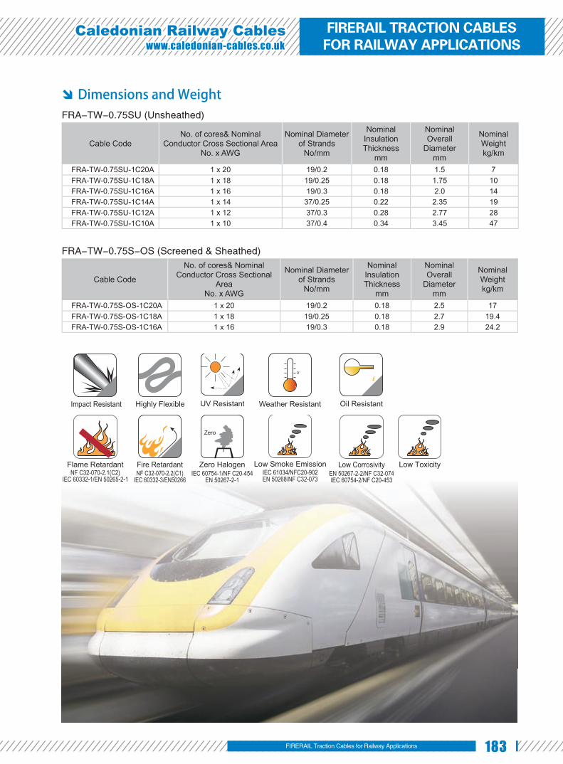
183
Caledonian Railway Cableswww.caledonian-cables.co.uk
Dimensions and Weight FRA-TW-0.75SU (Unsheathed)
Cable CodeNo. of cores& Nominal
Conductor Cross Sectional AreaNo. x AWG
Nominal Diameter of Strands
No/mm
Nominal Insulation Thickness
mm
Nominal Overall
Diametermm
Nominal Weightkg/km
FRA-TW-0.75SU-1C20A 1 x 20 19/0.2 0.18 1.5 7FRA-TW-0.75SU-1C18A 1 x 18 19/0.25 0.18 1.75 10FRA-TW-0.75SU-1C16A 1 x 16 19/0.3 0.18 2.0 14FRA-TW-0.75SU-1C14A 1 x 14 37/0.25 0.22 2.35 19FRA-TW-0.75SU-1C12A 1 x 12 37/0.3 0.28 2.77 28FRA-TW-0.75SU-1C10A 1 x 10 37/0.4 0.34 3.45 47
FRA-TW-0.75S-OS (Screened & Sheathed)
Cable Code
No. of cores& Nominal Conductor Cross Sectional
AreaNo. x AWG
Nominal Diameter of Strands
No/mm
Nominal Insulation Thickness
mm
Nominal Overall
Diametermm
Nominal Weightkg/km
FRA-TW-0.75S-OS-1C20A 1 x 20 19/0.2 0.18 2.5 17FRA-TW-0.75S-OS-1C18A 1 x 18 19/0.25 0.18 2.7 19.4FRA-TW-0.75S-OS-1C16A 1 x 16 19/0.3 0.18 2.9 24.2
Impact Resistant Highly Flexible UV Resistant Weather Resistant Oil Resistant
Flame RetardantNF C32-070-2.1(C2)
IEC 60332-1/EN 50265-2-1NF C32-070-2.2(C1)
IEC 60332-3/EN50266
Fire Retardant Zero HalogenIEC 60754-1/NF C20-454
EN 50267-2-1
Zero
Low Smoke EmissionIEC 61034/NFC20-902EN 50268/NF C32-073
EN 50267-2-2/NF C32-074IEC 60754-2/NF C20-453
Low Corrosivity Low Toxicity
FIRERAIL Traction Cables for Railway Applications
FIRERAIL TRACTION CABLES FOR RAILWAY APPLICATIONS

184 www.addison-cables.com
0.45/0.75KV Multicore Thin Wall Traction Cables
Applications Multicore power and control cable designed for protected, fi xed installation
inside and outside railway vehicles for connecting fi xed and moving parts.
Standard BS 6853 -1a ●
DIN 5510-1 1-4 ●
NFF 16-101 F0 ●
Construction Conductors: Circular Class 5 stranded ●
plain or tinned copper to BS EN 60228: 2005
/ BS 6360
I n s u l a t i o n : E l e c t r o n b e a m ●
crosslinkable thin wall LSZH compound
Outer Sheath: Electron beam crosslinkable LSZH compound ●
Optional FRA-TW-0.75M-OS (Screened)
FRA-TW-0.75M-FR (Fire resistant)
Electrical Characteristics at 20℃ Nominal Conductor Cross Section AWG 20 18 16 14 12 10Maximum Conductor Resistance Ω/km 28.3 17.9 14.1 8.3 6.8 3.6Voltage Rating KV 0.45/0.75
Mechanical and Thermal Properties Minimum Bending Radius: 3×OD (OD<12mm); 4×OD (OD>12mm) ●
Temperature Range: -40℃ to +120℃ ●
Electron Beam Crosslinkable LSZH Sheath
Electron Beam Crosslinkable LSZH Insulation
Stranded Plain/Tinned Copper Conductor

185
Caledonian Railway Cableswww.caledonian-cables.co.uk
Dimensions and Weight
Cable Code
No. of cores& Nominal Conductor Cross Sectional Area
No. x AWG
Nominal Diameter of Strands
No/mm
Nominal Insulation Thickness
mm
Nominal Overall Diameter
mm
Nominal Weightkg/km
FRA-TW-0.75M-2C20A 2×20 19/0.2 0.18 4.2 32FRA-TW-0.75M-2C18A 2×18 19/0.25 0.18 4.6 39FRA-TW-0.75M-2C16A 2×16 19/0.3 0.18 5.3 54FRA-TW-0.75M-2C14A 2×14 37/0.25 0.22 6.1 66FRA-TW-0.75M-2C12A 2×12 37/0.3 0.28 7.3 92FRA-TW-0.75M-3C20A 3×20 19/0.2 0.18 4.4 46FRA-TW-0.75M-3C18A 3×18 19/0.25 0.18 4.95 62FRA-TW-0.75M-4C20A 4×20 19/0.2 0.18 4.65 59FRA-TW-0.75M-4C18A 4×18 19/0.25 0.18 5.2 80FRA-TW-0.75M-4C16A 4×16 19/0.3 0.18 6.0 104
Impact Resistant Highly Flexible UV Resistant Weather Resistant Oil Resistant
Flame RetardantNF C32-070-2.1(C2)
IEC 60332-1/EN 50265-2-1NF C32-070-2.2(C1)
IEC 60332-3/EN50266
Fire Retardant Zero HalogenIEC 60754-1/NF C20-454
EN 50267-2-1
Zero
Low Smoke EmissionIEC 61034/NFC20-902EN 50268/NF C32-073
EN 50267-2-2/NF C32-074IEC 60754-2/NF C20-453
Low Corrosivity Low Toxicity
FIRERAIL Traction Cables for Railway Applications
FIRERAIL TRACTION CABLES FOR RAILWAY APPLICATIONS

186 www.addison-cables.com
0.6/1KV Single Core Medium Wall Traction Cables
Applications Single Core power and control cable designed for protected, fi xed installation
inside and outside railway vehicles for connecting fi xed and moving parts.
Standard BS 6853 -1a ●
DIN 5510-1 1-4 ●
NFF 16-101 F0 ●
Construction Conductors: Circular Class 5 stranded ●
plain or tinned copper to BS EN 60228: 2005 / BS 6360.
Insulation: Electron beam crosslinkable ●medium wall LSZH compound.
Optional FRA-MW-1S (Sheathed); FRA-MW-1S-OS (Screened & Sheathed)
FRA-MW-1SU-FR (Fire resistant & Unsheathed)
Electrical Characteristics at 20℃ Nominal Conductor Cross Section mm² 0.5 0.75 1.0 1.5 2.5 4.0 6.0Maximum Conductor Resistance Ω/km 40.1 26.7 20.0 13.7 8.21 5.09 3.39Voltage Rating KV 0.6/1.0
Nominal Conductor Cross Section mm² 10 16 25 35 50 70 95Maximum Conductor Resistance Ω/km 1.95 1.24 0.795 0.565 0.393 0.277 0.21Voltage Rating KV 0.6/1.0
Nominal Conductor Cross Section mm² 120 150 185 240 300 400Maximum Conductor Resistance Ω/km 0.164 0.132 0.108 0.0817 0.0654 0.0495Voltage Rating KV 0.6/1.0
Mechanical and Thermal Properties Minimum Bending Radius: 3×OD (OD<12mm); 4×OD (OD>12mm) ●Temperature Range: -40℃ to +120℃ ●
Stranded Plain/Tinned Copper Conductor
Electron Beam Crosslinkable LSZH Insulation

187
Caledonian Railway Cableswww.caledonian-cables.co.uk
Dimensions and Weight
Cable CodeNo. of cores& Nominal
Conductor Cross Sectional Area No.×mm²
Nominal Diameter of Strands
No/mm
Nominal Insulation Thickness
mm
Nominal Overall
Diametermm
Nominal Weightkg/km
FRA-MW-1SU-1G0.5 1×0.5 16/0.2 0.6 2.0 6FRA-MW-1SU-1G0.75 1×0.75 24/0.2 0.6 2.2 8FRA-MW-1SU-1G1 1×1.0 32/0.2 0.6 2.6 10FRA-MW-1SU-1G1.5 1×1.5 30/0.25 0.7 3.1 20FRA-MW-1SU-1G2.5 1×2.5 50/0.25 0.7 3.5 30FRA-MW-1SU-1G4 1×4.0 56/0.3 0.7 4.1 50FRA-MW-1SU-1G6 1×6.0 84/0.3 0.7 4.6 60FRA-MW-1SU-1G10 1×10 80/0.4 0.7 5.5 110FRA-MW-1SU-1G16 1×16 126/0.4 0.7 6.7 160FRA-MW-1SU-1G25 1×25 196/0.40 0.9 8.5 240FRA-MW-1SU-1G35 1×35 276/0.40 0.9 9.8 330FRA-MW-1SU-1G50 1×50 396/0.40 1.0 11.5 460FRA-MW-1SU-1G70 1×70 360/0.50 1.0 13.6 660FRA-MW-1SU-1G95 1×95 475/0.50 1.1 15.1 860FRA-MW-1SU-1G120 1×120 608/0.50 1.1 17.1 1080FRA-MW-1SU-1G150 1×150 756/0.50 1.4 19.1 1370FRA-MW-1SU-1G185 1×185 925/0.50 1.6 21.3 1690FRA-MW-1SU-1G240 1×240 1221/0.50 1.7 24.1 2230FRA-MW-1SU-1G300 1×300 1525/0.50 1.8 26.7 2780FRA-MW-1SU-1G400 1×400 2013/0.50 2.0 30.5 3740
Impact Resistant Highly Flexible UV Resistant Weather Resistant Oil Resistant
Flame RetardantNF C32-070-2.1(C2)
IEC 60332-1/EN 50265-2-1NF C32-070-2.2(C1)
IEC 60332-3/EN50266
Fire Retardant Zero HalogenIEC 60754-1/NF C20-454
EN 50267-2-1
Zero
Low Smoke EmissionIEC 61034/NFC20-902EN 50268/NF C32-073
EN 50267-2-2/NF C32-074IEC 60754-2/NF C20-453
Low Corrosivity Low Toxicity
FIRERAIL Traction Cables for Railway Applications
FIRERAIL TRACTION CABLES FOR RAILWAY APPLICATIONS

188 www.addison-cables.com
0.6/1KV Multicore Medium Wall Traction Cables
Applications Multicore power and control cable designed for protected, fi xed installation
inside and outside railway vehicles for connecting fi xed and moving parts.
Standard BS 6853 -1a ●
DIN 5510-1 1-4 ●
NFF 16-101 F0 ●
Construction Conductors: Circular Class 5 stranded ●
plain or tinned copper to BS EN 60228: 2005
/ BS 6360.
Insulation: Electron beam crosslinkable ●
medium wall LSZH compound.
Screening (optional) : Copper Wire Screen(for screened cables). ●
Outer Sheath: Electron beam crosslinkable LSZH compound. ●
Optional FRA-MW-1M-FR (Fire resistant)
Electrical Characteristics at 20℃ Nominal Conductor Cross Section mm² 0.5 0.75 1.0 1.5 2.5 4.0 6.0Maximum Conductor Resistance Ω/km 40.1 26.7 20.0 13.7 8.21 5.09 3.39Voltage Rating KV 0.6/1.0
Nominal Conductor Cross Section mm² 10 16 25 35 50Maximum Conductor Resistance Ω/km 1.95 1.24 0.795 0.565 0.393Voltage Rating KV 0.6/1.0
Mechanical and Thermal Properties Minimum Bending Radius: 3×OD (OD<12mm); 4×OD (OD>12mm) ●
Temperature Range: -40℃ to +120℃ ●
Stranded Plain/Tinned Copper Conductor
Electron Beam Crosslinkable LSZH Sheath
Electron Beam Crosslinkable LSZH Insulation
Optional Copper Wire Screen

189
Caledonian Railway Cableswww.caledonian-cables.co.uk
Dimensions and Weight FRA-MW-1M (Multicore unscreened)
Cable Code
No. of cores& Nominal Conductor Cross Sectional Area
No.×mm²
Nominal Diameter of StrandsNo/mm
Nominal Insulation Thickness
mm
Nominal Overall
Diametermm
Nominal Weightkg/km
FRA-MW-1M-2G0.5 2×0.5 16/0.20 0.6 5.9 48FRA-MW-1M-4G0.5 4×0.5 16/0.20 0.6 7.0 55FRA-MW-1M-7G0.5 7×0.5 16/0.20 0.6 9.1 72FRA-MW-1M-18G0.5 18×0.5 16/0.20 0.6 12.7 86FRA-MW-1M-3G0.75 3×0.75 24/0.20 0.6 6.8 70FRA-MW-1M-5G0.75 5×0.75 24/0.20 0.6 8.4 107FRA-MW-1M-8G0.75 8×0.75 24/0.20 0.6 10.9 147FRA-MW-1M-12G0.75 12×0.75 24/0.20 0.6 11.9 175FRA-MW-1M-20G0.75 20×0.75 24/0.20 0.6 15.2 350FRA-MW-1M-2G1 2×1.0 32/0.20 0.6 6.9 72FRA-MW-1M-6G1 6×1.0 32/0.20 0.6 10.0 160FRA-MW-1M-9G1 9×1.0 32/0.20 0.6 12.5 210FRA-MW-1M-25G1 25×1.0 32/0.20 0.6 18.7 519FRA-MW-1M-2G1.5 2×1.5 30/0.25 0.7 7.5 86FRA-MW-1M-3G1.5 3×1.5 30/0.25 0.7 8.0 90FRA-MW-1M-5G1.5 5×1.5 30/0.25 0.7 10.2 169FRA-MW-1M-7G1.5(G/Y) *7G 1.5 30/0.25 0.7 12.1 238FRA-MW-1M-12G1.5 12×1.5 30/0.25 0.7 14.2 313FRA-MW-1M-36G1.5 36×1.5 30/0.25 0.7 23 905
*G—yellow/green
FRA-MW-1M-OS (Multicore screened)
Cable Code
No. of cores& Nominal Conductor Cross Sectional Area
No.×mm²
Nominal Diameter of StrandsNo/mm
Nominal Insulation Thickness
mm
Nominal Overall
Diametermm
Nominal Weightkg/km
FRA-MW-1M-OS-2G0.5 2×0.5 16/0.20 0.6 6.6 68FRA-MW-1M-OS-4G0.5 4×0.5 16/0.20 0.6 7.5 102FRA-MW-1M-OS-7G0.5 7×0.5 16/0.20 0.6 9.8 145FRA-MW-1M-OS-15G0.5 15×0.5 16/0.20 0.6 13.4 240FRA-MW-1M-OS-9P0.5S 9×2×0.5 16/0.20 0.6 20.6 541FRA-MW-1M-OS-3G0.75 3×0.75 24/0.20 0.6 7.5 94FRA-MW-1M-OS-6G0.75 6×0.75 24/0.20 0.6 9.9 165FRA-MW-1M-OS-9G0.75 9×0.75 24/0.20 0.6 12.3 243FRA-MW-1M-OS-16G0.75 16×0.75 24/0.20 0.6 14.4 348FRA-MW-1M-OS-5P0.75S 5×2×0.75 24/0.20 0.6 16.0 354FRA-MW-1M-OS-4G1 4×1.0 32/0.20 0.6 8.8 140FRA-MW-1M-OS-7G1 7×1.0 32/0.20 0.6 11.8 226FRA-MW-1M-OS-3G1.5 3×1.5 32/0.25 0.7 8.6 124FRA-MW-1M-OS-5G1.5 5×1.5 32/0.25 0.7 10.9 208FRA-MW-1M-OS-9G1.5 9×1.5 30/0.25 0.7 14.9 409FRA-MW-1M-OS-16G1.5 16×1.5 30/0.25 0.7 17.5 560FRA-MW-1M-OS-6P1.5S 6×2×1.5 30/0.25 0.7 18.9 540FRA-MW-1M-OS-2G2.5 2×2.5 50/0.25 0.7 9.6 160FRA-MW-1M-OS-4G2.5 4×2.5 50/0.25 0.7 11.3 222FRA-MW-1M-OS-7G2.5 7×2.5 50/0.25 0.7 14.8 400FRA-MW-1M-OS-3G4 3×4 56/0.30 0.7 11.8 260FRA-MW-1M-OS-5G4 5×4 56/0.30 0.7 14.7 440FRA-MW-1M-OS-3G6 3×6 84/0.30 0.7 13.8 370FRA-MW-1M-OS-5G6 5×6 84/0.30 0.7 17.4 620FRA-MW-1M-OS-3G10 3×10 80/0.40 0.7 17.1 580
FIRERAIL Traction Cables for Railway Applications
FIRERAIL TRACTION CABLES FOR RAILWAY APPLICATIONS

190 www.addison-cables.com
Cable Code
No. of cores& Nominal Conductor Cross Sectional Area
No.×mm²
Nominal Diameter of StrandsNo/mm
Nominal Insulation Thickness
mm
Nominal Overall
Diametermm
Nominal Weightkg/km
FRA-MW-1M-OS-4G10 4×10 80/0.40 0.7 19.2 750FRA-MW-1M-OS-5G10 5×10 80/0.40 0.7 21.1 850FRA-MW-1M-OS-3G16 3×16 126/0.40 0.7 20.5 820FRA-MW-1M-OS-2G25 2×25 196/0.40 0.9 22.9 990FRA-MW-1M-OS-3G35 3×35 276/0.40 0.9 27.9 1600FRA-MW-1M-OS-6G35 6×35 276/0.40 0.9 39.7 3390FRA-MW-1M-OS-2G50 2×50 396/0.40 1.0 29.8 1760
Impact Resistant Highly Flexible UV Resistant Weather Resistant Oil Resistant
Flame RetardantNF C32-070-2.1(C2)
IEC 60332-1/EN 50265-2-1NF C32-070-2.2(C1)
IEC 60332-3/EN50266
Fire Retardant Zero HalogenIEC 60754-1/NF C20-454
EN 50267-2-1
Zero
Low Smoke EmissionIEC 61034/NFC20-902EN 50268/NF C32-073
EN 50267-2-2/NF C32-074IEC 60754-2/NF C20-453
Low Corrosivity Low Toxicity

191
Caledonian Railway Cableswww.caledonian-cables.co.uk
0.6/1KV Single Core Thin Wall Traction Cables
Applications Single core power and control cable designed for protected, fi xed installation
inside and outside railway vehicles for connecting fi xed and moving parts.
Standard BS 6853 -1a ●
DIN 5510-1 1-4 ●
NFF 16-101 F0 ●
Construction Conductors: Circular Class 5 stranded ●
plain or tinned copper to BS EN 60228: 2005
/ BS 6360.
Insulation: Electron beam crosslinkable ●
thin wall LSZH compound.
Optional FRA-TW-1SU-FR (Fire resistant & Unsheathed)
Electrical Characteristics at 20℃ Nominal Conductor Cross Section mm² 0.5 0.6 0.75 1.0 1.2 1.5 2.0 2.5 4.0
Maximum Conductor Resistance Ω/km 40.1 33.4 26.7 20 16.3 13.7 11.2 8.21 5.09
Voltage Rating KV 0.6/1.0
Mechanical and Thermal Properties Minimum Bending Radius: 3×OD (OD<12mm); 4×OD (OD>12mm) ●
Temperature Range: -40℃ to +120℃ ●
Stranded Plain/Tinned Copper Conductor
Electron Beam Crosslinkable LSZH Insulation
FIRERAIL Traction Cables for Railway Applications
FIRERAIL TRACTION CABLES FOR RAILWAY APPLICATIONS

192 www.addison-cables.com
Dimensions and Weight
Cable Code
No. of cores& Nominal Conductor Cross Sectional
Area No.×mm²
Nominal Diameter of Strands
No/mm
Nominal Insulation Thickness
mm
Nominal Overall Diameter
mm
Nominal Weightkg/km
FRA-TW-1SU-1C0.5S 1×0.5 19/0.18 0.3 1.4 5.8FRA-TW-1SU-1C0.6S 1×0.6 19/0.20 0.3 1.5 7FRA-TW-1SU-1C0.75S 1×0.75 19/0.22 0.3 1.6 8.4FRA-TW-1SU-1C1S 1×1.0 19/0.26 0.3 1.75 10FRA-TW-1SU-1C1.2S 1×1.2 19/0.28 0.3 2.0 13FRA-TW-1SU-1C1.5S 1×1.5 19/0.30 0.3 2.15 16FRA-TW-1SU-1C2S 1×2.0 37/0.25 0.4 2.4 19FRA-TW-1SU-1C2.5S 1×2.5 19/0.40 0.4 2.75 26FRA-TW-1SU-1C4S 1×4.0 56/0.30 0.4 3.35 40
Impact Resistant Highly Flexible UV Resistant Weather Resistant Oil Resistant
Flame RetardantNF C32-070-2.1(C2)
IEC 60332-1/EN 50265-2-1NF C32-070-2.2(C1)
IEC 60332-3/EN50266
Fire Retardant Zero HalogenIEC 60754-1/NF C20-454
EN 50267-2-1
Zero
Low Smoke EmissionIEC 61034/NFC20-902EN 50268/NF C32-073
EN 50267-2-2/NF C32-074IEC 60754-2/NF C20-453
Low Corrosivity Low ToxicityNF C32-070-2.1(C2)
IEC 60332-1/EN 50265-2-1NF C32-070-2.2(C1)
IEC 60332-3/EN50266IEC 60754-1/NF C20-454
EN 50267-2-1IEC 61034/NFC20-902EN 50268/NF C32-073
EN 50267-2-2/NF C32-074IEC 60754-2/NF C20-453
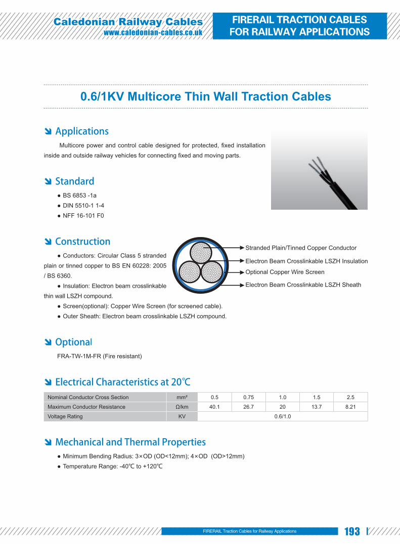
193
Caledonian Railway Cableswww.caledonian-cables.co.uk
0.6/1KV Multicore Thin Wall Traction Cables
Applications Multicore power and control cable designed for protected, fi xed installation
inside and outside railway vehicles for connecting fi xed and moving parts.
Standard BS 6853 -1a ●
DIN 5510-1 1-4 ●
NFF 16-101 F0 ●
Construction Conductors: Circular Class 5 stranded ●
plain or tinned copper to BS EN 60228: 2005
/ BS 6360.
Insulation: Electron beam crosslinkable ●
thin wall LSZH compound.
Screen(optional): Copper Wire Screen (for screened cable). ●
Outer Sheath: Electron beam crosslinkable LSZH compound. ●
Optiona lFRA-TW-1M-FR (Fire resistant)
Electrical Characteristics at 20℃ Nominal Conductor Cross Section mm² 0.5 0.75 1.0 1.5 2.5
Maximum Conductor Resistance Ω/km 40.1 26.7 20 13.7 8.21
Voltage Rating KV 0.6/1.0
Mechanical and Thermal Properties Minimum Bending Radius: 3×OD (OD<12mm); 4×OD (OD>12mm) ●
Temperature Range: -40℃ to +120℃ ●
Stranded Plain/Tinned Copper Conductor
Electron Beam Crosslinkable LSZH Sheath
Electron Beam Crosslinkable LSZH Insulation
Optional Copper Wire Screen
FIRERAIL Traction Cables for Railway Applications
FIRERAIL TRACTION CABLES FOR RAILWAY APPLICATIONS

194 www.addison-cables.com
Dimensions and Weight FRA-TW-1M (Multicore unscreened)
Cable Code
No. of cores& Nominal Conductor
Cross Sectional Area No.×mm²
Nominal Diameter of
StrandsNo/mm
Nominal Insulation Thickness
mm
Nominal Overall Diameter
mm
Nominal Weightkg/km
FRA-TW-1M-2C0.5S 2×0.5 19/0.18 0.3 4.4 31FRA-TW-1M-3C0.5S 3×0.5 19/0.18 0.3 4.6 36FRA-TW-1M-4C0.5S 4×0.5 19/0.18 0.3 5.0 43FRA-TW-1M-5C0.5S 5×0.5 19/0.18 0.3 5.5 53FRA-TW-1M-6C0.5S 6×0.5 19/0.18 0.3 6.0 62FRA-TW-1M-2P0.5S 2×2×0.5 19/0.18 0.3 6.5 58FRA-TW-1M-4P0.5S 4×2×0.5 19/0.18 0.3 8.7 99FRA-TW-1M-2C0.75S 2×0.75 19/0.22 0.3 4.75 35FRA-TW-1M-3C0.75S 3×0.75 19/0.22 0.3 5.15 47FRA-TW-1M-4C0.75S 4×0.75 19/0.22 0.3 5.6 57FRA-TW-1M-6C0.75S 6×0.75 19/0.22 0.3 6.75 83FRA-TW-1M-2P0.75S 2×2×0.75 19/0.22 0.3 7.75 81FRA-TW-1M-2C1S 2×1.0 19/0.25 0.3 5.1 45FRA-TW-1M-3C1S 3×1.0 19/0.25 0.3 5.4 54FRA-TW-1M-4C1S 4×1.0 19/0.25 0.3 5.8 64FRA-TW-1M-6C1S 6×1.0 19/0.25 0.3 7.3 98FRA-TW-1M-10C1S 10×1.0 19/0.25 0.3 8.7 143FRA-TW-1M-25C1S 25×1.0 19/0.25 0.3 12.8 324FRA-TW-1M-2C1.5S 2×1.5 19/0.3 0.3 6.0 63FRA-TW-1M-3C1.5S 3×1.5* 19/0.3 0.3 6.3 76FRA-TW-1M-4C1.5S 4×1.5 19/0.3 0.3 6.9 94FRA-TW-1M-5C1.5S 5×1.5* 19/0.3 0.3 7.8 116FRA-TW-1M-6C1.5S 6×1.5 19/0.3 0.3 8.45 141FRA-TW-1M-7C1.5S(G/Y) 7G 1.5 19/0.3 0.3 9.1 165FRA-TW-1M-8C1.5S 8×1.5 19/0.3 0.3 10.3 201FRA-TW-1M-10C1.5S 10×1.5 19/0.3 0.3 10.6 216FRA-TW-1M-18C1.5S 18×1.5 19/0.3 0.3 13.4 374FRA-TW-1M-25C1.5S(G/Y) 25G 1.5 19/0.3 0.3 15.5 494FRA-TW-1M-2C2.5S 2×2.5 19/0.4 0.4 7.3 98FRA-TW-1M-3C2.5S 3×2.5* 19/0.4 0.4 7.8 122FRA-TW-1M-4C2.5S 4×2.5 19/0.4 0.4 8.7 152FRA-TW-1M-5C2.5S 5×2.5 19/0.4 0.4 9.4 181FRA-TW-1M-6C2.5S 6×2.5 19/0.4 0.4 10.6 223
*earth cable can be offered as an option
G: earth cable (yellow/green)
FRA-TW-1M-OS (Multicore screened)
Cable Code
No. of cores& Nominal Conductor Cross Sectional Area
No.×mm²
Nominal Diameter of
StrandsNo/mm
Nominal Insulation Thickness
mm
Nominal Overall
Diametermm
Nominal Weightkg/km
FRA-TW-1M-OS-2C0.5S 2×0.5 19/0.18 0.3 4.8 42FRA-TW-1M-OS-3C0.5S 3×0.5 19/0.18 0.3 5.3 51FRA-TW-1M-OS-4C0.5S 4×0.5 19/0.18 0.3 5.4 56FRA-TW-1M-OS-6C0.5S 6×0.5 19/0.18 0.3 6.5 82FRA-TW-1M-OS-15C0.5S 15×0.5 19/0.18 0.3 9.0 167FRA-TW-1M-OS-2P0.5S 2×2×0.5 19/0.18 0.3 7.2 80FRA-TW-1M-OS-3P0.5S 3×2×0.5 19/0.18 0.3 8.1 98FRA-TW-1M-OS-4P0.5S 4×2×0.5 19/0.18 0.3 9.3 131FRA-TW-1M-OS-12P0.5S 12×2×0.5 19/0.18 0.3 13.0 276

195
Caledonian Railway Cableswww.caledonian-cables.co.uk
Cable Code
No. of cores& Nominal Conductor Cross Sectional Area
No.×mm²
Nominal Diameter of
StrandsNo/mm
Nominal Insulation Thickness
mm
Nominal Overall
Diametermm
Nominal Weightkg/km
FRA-TW-1M-OS-2C0.75S 2×0.75 19/0.22 0.3 5.0 48FRA-TW-1M-OS-4C0.75S 4×0.75 19/0.22 0.3 6.0 72FRA-TW-1M-OS-6C0.75S 6×0.75 19/0.22 0.3 7.2 103FRA-TW-1M-OS-10C0.75S 10×0.75 19/0.22 0.3 8.7 152FRA-TW-1M-OS-18C0.75S 18×0.75 19/0.22 0.3 11.0 244FRA-TW-1M-OS-3P0.75S 3×2×0.75 19/0.22 0.3 9.0 127FRA-TW-1M-OS-2C1S 2×1.0 19/0.25 0.3 5.6 60FRA-TW-1M-OS-3C1S 3×1.0 19/0.25 0.3 6.0 76FRA-TW-1M-OS-4C1S 4×1.0 19/0.25 0.3 6.5 88FRA-TW-1M-OS-6C1S 6×1.0 19/0.25 0.3 7.8 114FRA-TW-1M-OS-8C1S 8×1.0 19/0.25 0.3 8.9 171FRA-TW-1M-OS-25C1S 25×1.0 19/0.25 0.3 13.8 392FRA-TW-1M-OS-2P1S 2×2×1.0 19/0.25 0.3 8.3 117FRA-TW-1M-OS-2C1.5S 2×1.5 19/0.3 0.3 6.5 86FRA-TW-1M-OS-3C1.5S 3×1.5 19/0.3 0.3 6.8 95FRA-TW-1M-OS-4C1.5S 4×1.5 19/0.3 0.3 7.4 118FRA-TW-1M-OS-6C1.5S 6×1.5 19/0.3 0.3 9.0 168FRA-TW-1M-OS-18C1.5S 18×1.5 19/0.3 0.3 14.4 452FRA-TW-1M-OS-2C2.5S 2×2.5 19/0.4 0.4 7.8 122FRA-TW-1M-OS-4C2.5S 4×2.5 19/0.4 0.4 8.4 152FRA-TW-1M-OS-6C2.5S 6×2.5 19/0.4 0.4 11.4 268
Impact Resistant Highly Flexible UV Resistant Weather Resistant Oil Resistant
Flame RetardantNF C32-070-2.1(C2)
IEC 60332-1/EN 50265-2-1NF C32-070-2.2(C1)
IEC 60332-3/EN50266
Fire Retardant Zero HalogenIEC 60754-1/NF C20-454
EN 50267-2-1
Zero
Low Smoke EmissionIEC 61034/NFC20-902EN 50268/NF C32-073
EN 50267-2-2/NF C32-074IEC 60754-2/NF C20-453
Low Corrosivity Low Toxicity
FIRERAIL Traction Cables for Railway Applications
FIRERAIL TRACTION CABLES FOR RAILWAY APPLICATIONS

196 www.addison-cables.com
0.6/1KV Single Core Dual Wall Traction Cables
Applications Single Core power and control cable designed for protected, fi xed installation
inside and outside railway vehicles for connecting fi xed and moving parts
Standards BS 6853 -1a ●
DIN 5510-1 1-4 ●
NFF 16-101 F0 ●
Construction Conductors: Circular Class 5 stranded ●
plain or tinned copper to BS EN 60228: 2005 /
BS 6360.
Insulation 1: Electron beam crosslinkable ●
thin wall LSZH compound.
Insulation 2: Electron beam crosslinkable thin wall LSZH compound. ●
Optional FRA-DW-1S (Sheathed); FRA-DW-1S-OS (Screened & Sheathed);
FRA-DW-1SU-FR (Fire resistant & Unsheathed)
Electrical Characteristics at 20℃ Nominal Conductor Cross Section mm² 0.5 0.6 0.75 1.0 1.2 1.5 2.5 3 4
Maximum Conductor Resistance Ω/km 40.1 31.1 26.7 20 15.5 13.7 8.21 6.56 5.09
Voltage Rating KV 0.6/1.0
Mechanical and Thermal Properties Minimum Bending Radius: 3×OD (OD<12mm); 4×OD (OD>12mm) ●
Temperature Range: -40℃ to +120℃ ●
Stranded Plain/Tinned Copper Conductor
ELectron Beam Crosslinkable LSZH Insulation
ELectron Beam Crosslinkable LSZH Sheath

197
Caledonian Railway Cableswww.caledonian-cables.co.uk
Dimensions and Weight
Cable CodeNo. of cores& Nominal
Conductor Cross Sectional Area No.×mm²
Nominal Diameter of Strands
No/mm
Nominal Insulation Thickness
mm
Nominal Overall
Diametermm
Nominal Weightkg/km
FRA-DW-1SU-1G0.5 1×0.5 19/0.18 0.2 1.3 5.5FRA-DW-1SU-1G0.6 1×0.6 19/0.20 0.2 1.39 6.5FRA-DW-1SU-1G0.75 1×0.75 19/0.22 0.2 1.52 8FRA-DW-1SU-1G1 1×1.0 19/0.26 0.2 1.67 10FRA-DW-1SU-1G1.2 1×1.2 19/0.28 0.2 1.83 12FRA-DW-1SU-1G1.5 1×1.5 19/0.30 0.3 2.04 15FRA-DW-1SU-1G2 1×2.0 37/0.25 0.3 2.29 19FRA-DW-1SU-1G2.5 1×2.5 19/0.40 0.3 2.54 24FRA-DW-1SU-1G3 1×3.0 37/0.32 0.3 2.78 29FRA-DW-1SU-1G4 1×4.0 56/0.30 0.4 3.21 39
Impact Resistant Highly Flexible UV Resistant Weather Resistant Oil Resistant
Flame RetardantNF C32-070-2.1(C2)
IEC 60332-1/EN 50265-2-1NF C32-070-2.2(C1)
IEC 60332-3/EN50266
Fire Retardant Zero HalogenIEC 60754-1/NF C20-454
EN 50267-2-1
Zero
Low Smoke EmissionIEC 61034/NFC20-902EN 50268/NF C32-073
EN 50267-2-2/NF C32-074IEC 60754-2/NF C20-453
Low Corrosivity Low Toxicity
FIRERAIL Traction Cables for Railway Applications
FIRERAIL TRACTION CABLES FOR RAILWAY APPLICATIONS

198 www.addison-cables.com
0.6/1KV Multicore Dual Wall Traction Cables
Applications Multicore unscreened and screened power and control cable designed for
protected, fi xed installation for connecting fi xed parts inside equipment.
Standards BS 6853 -1a ●
DIN 5510-1 1-4 ●
NFF 16-101 F0 ●
Construction Conductors: Circular Class 5 stranded ●
plain or tinned copper to BS EN 60228: 2005
/ BS 6360.
Insulation 1: Electron beam crosslinkable ●
thin wall LSZH compound.
Insulation 2: Electron beam crosslinkable ●
thin wall LSZH compound.
Screen (optional) : Copper Wire Screen ( screened cables ). ●
Outer Sheath: Electron beam crosslinkable LSZH compound. ●
Optional FRA-DW-1M-FR (Fire resistant )
Electrical Characteristics at 20℃ Nominal Conductor Cross Section mm² 0.25 0.5 0.75 1.0 1.5 2.5
Maximum Conductor Resistance Ω/km 88.5 40.1 26.7 20 13.7 8.21
Voltage Rating KV 0.6/1.0
Mechanical and Thermal Properties Minimum Bending Radius: 3×OD (OD<12mm); 4×OD (OD>12mm) ●
Temperature Range: -40℃ to +120℃ ●
Stranded Plain/Tinned Copper Conductor
Electron Beam Crosslinkable LSZH Sheath
Electron Beam Crosslinkable LSZH Insulation
Optional Copper Wire ScreenElectron Beam Crosslinkable LSZH Insulation

199
Caledonian Railway Cableswww.caledonian-cables.co.uk
Dimensions and Weight FRA-DW-1M (Multicore unscreened)
Cable Code
No. of cores& Nominal Conductor Cross Sectional
Area No.×mm²
Nominal Diameter of
StrandsNo/mm
Nominal Insulation Thickness
mm
Nominal Overall Diameter
mm
Nominal Weightkg/km
FRA-DW-1M-2C0.5S 2×0.5 19/0.18 0.2 4.0 24FRA-DW-1M-3C0.5S 3×0.5 19/0.18 0.2 4.6 36FRA-DW-1M-5C0.5S 5×0.5 19/0.18 0.2 5.0 43FRA-DW-1M-9C0.5S 9×0.5 19/0.18 0.2 6.7 66FRA-DW-1M-12C0.5S 12×0.5 19/0.18 0.2 6.9 89FRA-DW-1M-16C0.5S 16×0.5 19/0.18 0.2 7.8 115FRA-DW-1M-25C0.5S 25×0.5 19/0.18 0.2 9.5 170FRA-DW-1M-30C0.5S 30×0.5 19/0.18 0.2 10.1 205FRA-DW-1M-2P0.5S 2×2×0.5 19/0.18 0.2 5.8 50FRA-DW-1M-2C0.75S 2×0.75 19/0.22 0.2 4.4 32FRA-DW-1M-4C0.75S 4×0.75 19/0.22 0.2 5.0 49FRA-DW-1M-9C0.75S 9×0.75 19/0.22 0.2 7.7 106FRA-DW-1M-14C0.75S 14×0.75 19/0.22 0.2 8.4 140FRA-DW-1M-27C0.75S 27×0.75 19/0.22 0.2 11.3 270FRA-DW-1M-36C0.75S 36×0.75 19/0.22 0.2 12.8 360FRA-DW-1M-3C1S 3×1.0 19/0.25 0.2 5.0 47FRA-DW-1M-6C1S 6×1.0 19/0.25 0.2 6.6 88FRA-DW-1M-14C1S 14×1.0 19/0.25 0.2 9.1 174FRA-DW-1M-20C1S 20×1.0 19/0.25 0.2 11.2 256FRA-DW-1M-50C1S 50×1.0 19/0.25 0.2 16.8 620FRA-DW-1M-2C1.5S 2×1.5 37/0.22 0.3 5.4 55FRA-DW-1M-5C1.5S 5×1.5 37/0.22 0.3 7.1 110FRA-DW-1M-7C1.5S 7×1.5 37/0.22 0.3 8.4 150FRA-DW-1M-10C1.5S 10×1.5 37/0.22 0.3 9.9 170FRA-DW-1M-18C1.5S 18×1.5 37/0.22 0.3 12.4 350FRA-DW-1M-30C1.5S 30×1.5 37/0.22 0.3 15.6 560FRA-DW-1M-50C1.5S 50×1.5 37/0.22 0.3 20.1 870FRA-DW-1M-3C2.5S 3×2.5 37/0.29 0.3 7.0 105FRA-DW-1M-6C2.5S 6×2.5 37/0.29 0.3 9.6 200FRA-DW-1M-12C2.5S 12×2.5 37/0.29 0.3 12.6 360FRA-DW-1M-18C2.5S 18×2.5 37/0.29 0.3 15.3 545FRA-DW-1M-24C2.5S 24×2.5 37/0.29 0.3 17.8 695FRA-DW-1M-30C2.5S 30×2.5 37/0.29 0.3 19.3 870FRA-DW-1M-36C2.5S 36×2.5 37/0.29 0.3 21.0 1050
FRA-DW-1M-OS (Multicore screened)
Cable Code
No. of cores& Nominal Conductor Cross Sectional Area
No.×mm²
Nominal Diameter of
StrandsNo/mm
Nominal Insulation Thickness
mm
Nominal Overall
Diametermm
Nominal Weightkg/km
FRA-DW-1M-OS-2P0.25S 2×2×0.25 19/0.13 0.2 5.7 48.9FRA-DW-1M-OS-3P0.25S 3×2×0.25 19/0.13 0.2 6.1 57.2FRA-DW-1M-OS-4P0.25S 4×2×0.25 19/0.13 0.2 7.0 72FRA-DW-1M-OS-7P0.25S 7×2×0.25 19/0.13 0.2 7.8 92FRA-DW-1M-OS-25C0.25S 25×0.25 19/0.13 0.2 8.9 139FRA-DW-1M-OS-2C0.5S 2×0.5 19/0.18 0.2 4.3 34FRA-DW-1M-OS-3C0.5S 3×0.5 19/0.18 0.2 4.5 40FRA-DW-1M-OS-4C0.5S 4×0.5 19/0.18 0.2 4.8 47FRA-DW-1M-OS-5C0.5S 5×0.5 19/0.18 0.2 5.4 58FRA-DW-1M-OS-6C0.5S 6×0.5 19/0.18 0.2 5.9 70FRA-DW-1M-OS-7C0.5S 7×0.5 19/0.18 0.2 6.3 80FRA-DW-1M-OS-8C0.5S 8×0.5 19/0.18 0.2 6.8 86FRA-DW-1M-OS-9C0.5S 9×0.5 19/0.18 0.2 7.2 95FRA-DW-1M-OS-10C0.5S 10×0.5 19/0.18 0.2 7.2 101FRA-DW-1M-OS-12C0.5S 12×0.5 19/0.18 0.2 7.4 112FRA-DW-1M-OS-15C0.5S 15×0.5 19/0.18 0.2 8.5 135FRA-DW-1M-OS-16C0.5S 16×0.5 19/0.18 0.2 8.5 142
FIRERAIL Traction Cables for Railway Applications
FIRERAIL TRACTION CABLES FOR RAILWAY APPLICATIONS

200 www.addison-cables.com
Cable Code
No. of cores& Nominal Conductor Cross Sectional Area
No.×mm²
Nominal Diameter of
StrandsNo/mm
Nominal Insulation Thickness
mm
Nominal Overall
Diametermm
Nominal Weightkg/km
FRA-DW-1M-OS-18C0.5S 18×0.5 19/0.18 0.2 8.9 162FRA-DW-1M-OS-20C0.5S 20×0.5 19/0.18 0.2 9.3 185FRA-DW-1M-OS-22C0.5S 22×0.5 19/0.18 0.2 9.9 195FRA-DW-1M-OS-25C0.5S 25×0.5 19/0.18 0.2 10.3 213FRA-DW-1M-OS-27C0.5S 27×0.5 19/0.18 0.2 10.5 231FRA-DW-1M-OS-30C0.5S 30×0.5 19/0.18 0.2 11.3 265FRA-DW-1M-OS-36C0.5S 36×0.5 19/0.18 0.2 12.1 301FRA-DW-1M-OS-42C0.5S 42×0.5 19/0.18 0.2 12.9 360FRA-DW-1M-OS-48C0.5S 48×0.5 19/0.18 0.2 13.6 410FRA-DW-1M-OS-50C0.5S 50×0.5 19/0.18 0.2 14.2 430FRA-DW-1M-OS-2P0.5S 2×2×0.5 19/0.18 0.2 6.4 69FRA-DW-1M-OS-3P0.5S 3×2×0.5 19/0.18 0.2 6.7 80FRA-DW-1M-OS-4P0.5S 4×2×0.5 19/0.18 0.2 7.4 95FRA-DW-1M-OS-5P0.5S 5×2×0.5 19/0.18 0.2 9.2 136FRA-DW-1M-OS-6P0.5S 6×2×0.5 19/0.18 0.2 9.2 148FRA-DW-1M-OS-8P0.5S 8×2×0.5 19/0.18 0.2 9.7 155FRA-DW-1M-OS-10P0.5S 10×2×0.5 19/0.18 0.2 10.9 200FRA-DW-1M-OS-12P0.5S 12×2×0.5 19/0.18 0.2 12.1 240FRA-DW-1M-OS-15P0.5S 15×2×0.5 19/0.18 0.2 13.0 300FRA-DW-1M-OS-16P0.5S 16×2×0.5 19/0.18 0.2 13.0 320FRA-DW-1M-OS-20P0.5S 20×2×0.5 19/0.18 0.2 14.4 360FRA-DW-1M-OS-2T0.5S 2×3×0.5 19/0.18 0.2 7.3 90FRA-DW-1M-OS-2C0.75S 2×0.75 19/0.22 0.2 4.8 40FRA-DW-1M-OS-3C0.75S 3×0.75 19/0.22 0.2 5.0 50FRA-DW-1M-OS-4C0.75S 4×0.75 19/0.22 0.2 5.5 62FRA-DW-1M-OS-5C0.75S 5×0.75 19/0.22 0.2 6.1 75FRA-DW-1M-OS-6C0.75S 6×0.75 19/0.22 0.2 6.6 85FRA-DW-1M-OS-7C0.75S 7×0.75 19/0.22 0.2 7.2 100FRA-DW-1M-OS-8C0.75S 8×0.75 19/0.22 0.2 7.8 113FRA-DW-1M-OS-10C0.75S 10×0.75 19/0.22 0.2 8.1 130FRA-DW-1M-OS-12C0.75S 12×0.75 19/0.22 0.2 8.4 150FRA-DW-1M-OS-14C0.75S 14×0.75 19/0.22 0.2 9.1 170FRA-DW-1M-OS-16C0.75S 16×0.75 19/0.22 0.2 9.7 206FRA-DW-1M-OS-18C0.75S 18×0.75 19/0.22 0.2 10.2 230FRA-DW-1M-OS-20C0.75S 20×0.75 19/0.22 0.2 11.1 258FRA-DW-1M-OS-24C0.75S 24×0.75 19/0.22 0.2 12.0 294FRA-DW-1M-OS-25C0.75S 25×0.75 19/0.22 0.2 12.3 300FRA-DW-1M-OS-2P0.75S 2×2×0.75 19/0.22 0.2 7.1 86FRA-DW-1M-OS-3P0.75S 3×2×0.75 19/0.22 0.2 7.6 109FRA-DW-1M-OS-4P0.75S 4×2×0.75 19/0.22 0.2 9.9 143FRA-DW-1M-OS-5P0.75S 5×2×0.75 19/0.22 0.2 10.7 182FRA-DW-1M-OS-6P0.75S 6×2×0.75 19/0.22 0.2 11.9 227FRA-DW-1M-OS-7P0.75S 7×2×0.75 19/0.22 0.2 13.4 279FRA-DW-1M-OS-8P0.75S 8×2×0.75 19/0.22 0.2 13.2 291FRA-DW-1M-OS-10P0.75S 10×2×0.75 19/0.22 0.2 14.8 333FRA-DW-1M-OS-3T0.75S 3×3×0.75 19/0.22 0.2 8.9 151FRA-DW-1M-OS-5Q0.75S 5×4×0.75 19/0.22 0.2 12.8 290FRA-DW-1M-OS-2C1S 2×1.0 19/0.25 0.2 5.0 50FRA-DW-1M-OS-3C1S 3×1.0 19/0.25 0.2 5.5 60FRA-DW-1M-OS-4C1S 4×1.0 19/0.25 0.2 5.8 72FRA-DW-1M-OS-5C1S 5×1.0 19/0.25 0.2 6.6 88FRA-DW-1M-OS-6C1S 6×1.0 19/0.25 0.2 7.3 114FRA-DW-1M-OS-7C1S 7×1.0 19/0.25 0.2 7.9 134FRA-DW-1M-OS-8C1S 8×1.0 19/0.25 0.2 8.5 150FRA-DW-1M-OS-9C1S 9×1.0 19/0.25 0.2 8.9 160FRA-DW-1M-OS-10C1S 10×1.0 19/0.25 0.2 8.9 168FRA-DW-1M-OS-12C1S 12×1.0 19/0.25 0.2 9.2 188FRA-DW-1M-OS-16C1S 16×1.0 19/0.25 0.2 10.5 250FRA-DW-1M-OS-18C1S 18×1.0 19/0.25 0.2 11.2 275FRA-DW-1M-OS-25C1S 25×1.0 19/0.25 0.2 12.7 357FRA-DW-1M-OS-27C1S 27×1.0 19/0.25 0.2 13.3 395FRA-DW-1M-OS-30C1S 30×1.0 19/0.25 0.2 13.8 450FRA-DW-1M-OS-36C1S 36×1.0 19/0.25 0.2 15.2 530

201
Caledonian Railway Cableswww.caledonian-cables.co.uk
Cable Code
No. of cores& Nominal Conductor Cross Sectional Area
No.×mm²
Nominal Diameter of
StrandsNo/mm
Nominal Insulation Thickness
mm
Nominal Overall
Diametermm
Nominal Weightkg/km
FRA-DW-1M-OS-42C1S 42×1.0 19/0.25 0.2 16.3 605FRA-DW-1M-OS-50C1S 50×1.0 19/0.25 0.2 17.8 690FRA-DW-1M-OS-2P1S 2×2×1.0 19/0.25 0.2 7.9 107FRA-DW-1M-OS-4P1S 4×2×1.0 19/0.25 0.2 9.4 128FRA-DW-1M-OS-6P1S 6×2×1.0 19/0.25 0.2 11.6 240FRA-DW-1M-OS-12P1S 12×2×1.0 19/0.25 0.2 14.3 400FRA-DW-1M-OS-4T1S 4×3×1.0 19/0.25 0.2 11.5 230FRA-DW-1M-OS-3Q1S 3×4×1.0 19/0.25 0.2 11.3 245FRA-DW-1M-OS-4Q1S 4×4×1.0 19/0.25 0.2 12.5 267FRA-DW-1M-OS-2C1.5S 2×1.5 37/0.22 0.3 5.8 70FRA-DW-1M-OS-3C1.5S 3×1.5 37/0.22 0.3 6.1 81FRA-DW-1M-OS-4C1.5S 4×1.5 37/0.22 0.3 6.7 100FRA-DW-1M-OS-5C1.5S 5×1.5 37/0.22 0.3 7.7 135FRA-DW-1M-OS-6C1.5S 6×1.5 37/0.22 0.3 8.3 155FRA-DW-1M-OS-7C1.5S 7×1.5 37/0.22 0.3 9.1 184FRA-DW-1M-OS-8C1.5S 8×1.5 37/0.22 0.3 10.3 222FRA-DW-1M-OS-9C1.5S 9×1.5 37/0.22 0.3 10.5 234FRA-DW-1M-OS-10C1.5S 10×1.5 37/0.22 0.3 10.5 240FRA-DW-1M-OS-12C1.5S 12×1.5 37/0.22 0.3 10.9 268FRA-DW-1M-OS-14C1.5S(G/Y) 14G 1.5 37/0.22 0.3 12.2 333FRA-DW-1M-OS-16C1.5S 16×1.5 37/0.22 0.3 12.5 364FRA-DW-1M-OS-18C1.5S 18×1.5 37/0.22 0.3 13.2 405FRA-DW-1M-OS-25C1.5S 25×1.5* 37/0.22 0.3 15.8 562FRA-DW-1M-OS-48C1.5S 48×1.5 37/0.22 0.3 20.7 989FRA-DW-1M-OS-2P1.5S 2×2×1.5 37/0.22 0.3 9.2 153FRA-DW-1M-OS-3P1.5S 3×2×1.5 37/0.22 0.3 9.8 205FRA-DW-1M-OS-7P1.5S 7×2×1.5 37/0.22 0.3 12.6 330FRA-DW-1M-OS-2C2.5S 2×2.5 37/0.29 0.3 7.0 105FRA-DW-1M-OS-3C2.5S 3×2.5 37/0.29 0.3 7.6 130FRA-DW-1M-OS-4C2.5S 4×2.5 37/0.29 0.3 8.4 170FRA-DW-1M-OS-5C2.5S 5×2.5 37/0.29 0.3 9.4 190FRA-DW-1M-OS-6C2.5S 6×2.5 37/0.29 0.3 10.4 225FRA-DW-1M-OS-7C2.5S 7×2.5 37/0.29 0.3 11.4 270FRA-DW-1M-OS-8C2.5S 8×2.5 37/0.29 0.3 12.6 343FRA-DW-1M-OS-10C2.5S 10×2.5 37/0.29 0.3 13.2 370FRA-DW-1M-OS-12C2.5S 12×2.5 37/0.29 0.3 13.6 420FRA-DW-1M-OS-16C2.5S 16×2.5 37/0.29 0.3 15.7 560FRA-DW-1M-OS-18C2.5S 18×2.5 37/0.29 0.3 16.6 620FRA-DW-1M-OS-25C2.5S 25×2.5 37/0.29 0.3 19.3 835FRA-DW-1M-OS-27C2.5S 27×2.5 37/0.29 0.3 20.5 870FRA-DW-1M-OS-48C2.5S 48×2.5 37/0.29 0.3 25.7 1560
* earth cable (yellow/green) can be offered
Impact Resistant Highly Flexible UV Resistant Weather Resistant Oil Resistant
Flame RetardantNF C32-070-2.1(C2)
IEC 60332-1/EN 50265-2-1NF C32-070-2.2(C1)
IEC 60332-3/EN50266
Fire Retardant Zero HalogenIEC 60754-1/NF C20-454
EN 50267-2-1
Zero
Low Smoke EmissionIEC 61034/NFC20-902EN 50268/NF C32-073
EN 50267-2-2/NF C32-074IEC 60754-2/NF C20-453
Low Corrosivity Low Toxicity
FIRERAIL Traction Cables for Railway Applications
FIRERAIL TRACTION CABLES FOR RAILWAY APPLICATIONS

202 www.addison-cables.com
1.8/3KV Single Core Standard Wall Traction Cables
Applications Single Core power and control cable designed for protected, fi xed installation
inside and outside railway vehicles for connecting fi xed and moving parts in direct
current and alternating voltage technology, especially converter technology
Standard BS 6853 -1a ●
DIN 5510-1 1-4 ●
NFF 16-101 F0 ●
Construction Conductors: Circular Class 5 ●
stranded plain or tinned copper to BS
EN 60228: 2005 / BS 6360.
Insu la t ion: E lec t ron beam ●
crosslinkable standard wall LSZH compound.
Outer Sheath (optional): Electron beam crosslinkable LSZH compound (for sheathed cables). ●
Optional FRA-SW-3S-OS (Screened & Sheathed);
FRA-SW-3SU-FR(Fire resistant & Unsheathed)
Electrical Characteristics at 20℃ Nominal Conductor Cross Section mm² 1.5 2.5 4.0 6.0 10 16 25 35 50Maximum Conductor Resistance Ω/km 13.7 8.21 5.09 3.39 1.95 1.24 0.795 0.565 0.393Voltage Rating KV 1.8/3
Nominal Conductor Cross Section mm² 70 95 120 150 185 240 300 400Maximum Conductor Resistance Ω/km 0.277 0.21 0.164 0.132 0.108 0.0817 0.0654 0.0495Voltage Rating KV 1.8/3
Mechanical and Thermal Properties Minimum Bending Radius: 3×OD (OD<12mm); 4×OD (OD>12mm) ●
Temperature Range: -40℃ to +120℃ ●
Stranded Plain/Tinned Copper Conductor
Optional Electron Beam Crosslinkable LSZH Sheath
Electron Beam Crosslinkable LSZH Insulation
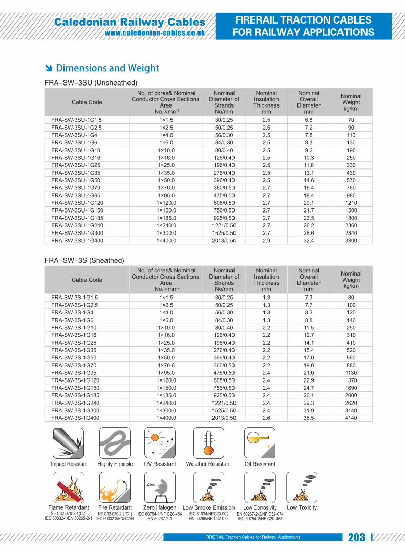
203
Caledonian Railway Cableswww.caledonian-cables.co.uk
Dimensions and Weight FRA-SW-3SU (Unsheathed)
Cable CodeNo. of cores& Nominal
Conductor Cross Sectional Area
No.×mm²
Nominal Diameter of
StrandsNo/mm
Nominal Insulation Thickness
mm
Nominal Overall
Diametermm
Nominal Weightkg/km
FRA-SW-3SU-1G1.5 1×1.5 30/0.25 2.5 6.8 70FRA-SW-3SU-1G2.5 1×2.5 50/0.25 2.5 7.2 90FRA-SW-3SU-1G4 1×4.0 56/0.30 2.5 7.8 110FRA-SW-3SU-1G6 1×6.0 84/0.30 2.5 8.3 130FRA-SW-3SU-1G10 1×10.0 80/0.40 2.5 9.2 190FRA-SW-3SU-1G16 1×16.0 126/0.40 2.5 10.3 250FRA-SW-3SU-1G25 1×25.0 196/0.40 2.5 11.8 330FRA-SW-3SU-1G35 1×35.0 276/0.40 2.5 13.1 430FRA-SW-3SU-1G50 1×50.0 396/0.40 2.5 14.6 570FRA-SW-3SU-1G70 1×70.0 360/0.50 2.7 16.4 760FRA-SW-3SU-1G95 1×95.0 475/0.50 2.7 18.4 980FRA-SW-3SU-1G120 1×120.0 608/0.50 2.7 20.1 1210FRA-SW-3SU-1G150 1×150.0 756/0.50 2.7 21.7 1500FRA-SW-3SU-1G185 1×185.0 925/0.50 2.7 23.5 1800FRA-SW-3SU-1G240 1×240.0 1221/0.50 2.7 26.2 2360FRA-SW-3SU-1G300 1×300.0 1525/0.50 2.7 28.6 2840FRA-SW-3SU-1G400 1×400.0 2013/0.50 2.9 32.4 3800
FRA-SW-3S (Sheathed)
Cable CodeNo. of cores& Nominal
Conductor Cross Sectional Area
No.×mm²
Nominal Diameter of
StrandsNo/mm
Nominal Insulation Thickness
mm
Nominal Overall
Diametermm
Nominal Weightkg/km
FRA-SW-3S-1G1.5 1×1.5 30/0.25 1.3 7.3 80FRA-SW-3S-1G2.5 1×2.5 50/0.25 1.3 7.7 100FRA-SW-3S-1G4 1×4.0 56/0.30 1.3 8.3 120FRA-SW-3S-1G6 1×6.0 84/0.30 1.3 8.8 140FRA-SW-3S-1G10 1×10.0 80/0.40 2.2 11.5 250FRA-SW-3S-1G16 1×16.0 126/0.40 2.2 12.7 310FRA-SW-3S-1G25 1×25.0 196/0.40 2.2 14.1 410FRA-SW-3S-1G35 1×35.0 276/0.40 2.2 15.4 520FRA-SW-3S-1G50 1×50.0 396/0.40 2.2 17.0 660FRA-SW-3S-1G70 1×70.0 360/0.50 2.2 19.0 880FRA-SW-3S-1G95 1×95.0 475/0.50 2.4 21.0 1130FRA-SW-3S-1G120 1×120.0 608/0.50 2.4 22.9 1370FRA-SW-3S-1G150 1×150.0 756/0.50 2.4 24.7 1690FRA-SW-3S-1G185 1×185.0 925/0.50 2.4 26.1 2000FRA-SW-3S-1G240 1×240.0 1221/0.50 2.4 29.3 2620FRA-SW-3S-1G300 1×300.0 1525/0.50 2.4 31.9 3140FRA-SW-3S-1G400 1×400.0 2013/0.50 2.6 35.5 4140
Impact Resistant Highly Flexible UV Resistant Weather Resistant Oil Resistant
Flame RetardantNF C32-070-2.1(C2)
IEC 60332-1/EN 50265-2-1NF C32-070-2.2(C1)
IEC 60332-3/EN50266
Fire Retardant Zero HalogenIEC 60754-1/NF C20-454
EN 50267-2-1
Zero
Low Smoke EmissionIEC 61034/NFC20-902EN 50268/NF C32-073
EN 50267-2-2/NF C32-074IEC 60754-2/NF C20-453
Low Corrosivity Low Toxicity
FIRERAIL Traction Cables for Railway Applications
FIRERAIL TRACTION CABLES FOR RAILWAY APPLICATIONS

204 www.addison-cables.com
1.8/3KV Single Core Medium Wall Traction Cables
Applications Single core power and control cable designed for protected, fi xed installation
inside and outside railway vehicles for connecting fi xed and moving parts in direct
current and alternating voltage technology, especially converter technology.
Standard BS 6853 -1a ●
DIN 5510-1 1-4 ●
NFF 16-101 F0 ●
Construction Conductors: Circular Class 5 ●
stranded plain or tinned copper to BS
EN 60228: 2005 / BS 6360.
Insu la t ion: E lec t ron beam ●
crosslinkable medium wall LSZH compound.
Outer Sheath: Electron beam crosslinkable LSZH compound (for sheathed cables). ●
Optional FRA-MW-3S-OS (Screened & Sheathed)
FRA-MW-3SU-FR(Fire resistant & Unsheathed)
Electrical Characteristics at 20℃ Nominal Conductor Cross Section mm² 1.5 2.5 4.0 6.0 10 16 25 35 50Maximum Conductor Resistance Ω/km 13.7 8.21 5.09 3.39 1.95 1.24 0.795 0.565 0.393Voltage Rating KV 1.8/3
Nominal Conductor Cross Section mm² 70 95 120 150 185 240 300 400Maximum Conductor Resistance Ω/km 0.277 0.21 0.164 0.132 0.108 0.0817 0.0654 0.0495Voltage Rating KV 1.8/3
Mechanical and Thermal Properties Minimum Bending Radius: 3×OD (OD<12mm); 4×OD (OD>12mm) ●
Temperature Range: -40℃ to +120℃ ●
Stranded Plain/Tinned Copper Conductor
Optional Electron Beam Crosslinkable LSZH Sheath
Electron Beam Crosslinkable LSZH Insulation

205
Caledonian Railway Cableswww.caledonian-cables.co.uk
Dimensions and Weight FRA-MW-3SU (Unsheathed)
Cable Code
No. of cores& Nominal Conductor Cross Sectional Area
No.×mm²
Nominal Diameter of Strands
No/mm
Nominal Insulation Thickness
mm
Nominal Overall
Diametermm
Nominal Weightkg/km
FRA-MW-3SU-1G1.5 1×1.5 30/0.25 2.0 5.8 50FRA-MW-3SU-1G2.5 1×2.5 50/0.25 2.0 6.2 60FRA-MW-3SU-1G4 1×4.0 56/0.30 2.0 6.8 80FRA-MW-3SU-1G6 1×6.0 84/0.30 2.0 7.3 100FRA-MW-3SU-1G10 1×10.0 80/0.40 2.0 8.2 150FRA-MW-3SU-1G16 1×16.0 126/0.40 2.0 9.3 220FRA-MW-3SU-1G25 1×25.0 196/0.40 2.0 10.8 290FRA-MW-3SU-1G35 1×35.0 276/0.40 2.0 12.1 390FRA-MW-3SU-1G50 1×50.0 396/0.40 2.0 13.6 530FRA-MW-3SU-1G70 1×70.0 360/0.50 2.0 15.4 720FRA-MW-3SU-1G95 1×95.0 475/0.50 2.2 17.4 940FRA-MW-3SU-1G120 1×120.0 608/0.50 2.2 19.1 1160FRA-MW-3SU-1G150 1×150.0 756/0.50 2.2 20.7 1440FRA-MW-3SU-1G185 1×185.0 925/0.50 2.4 22.7 1760FRA-MW-3SU-1G240 1×240.0 1221/0.50 2.4 25.6 2350FRA-MW-3SU-1G300 1×300.0 1525/0.50 2.4 27.9 2820FRA-MW-3SU-1G400 1×400.0 2013/0.50 2.6 31.7 3730
FRA-MW-3S (Sheathed)
Cable Code
No. of cores& Nominal Conductor Cross Sectional Area
No.×mm²
Nominal Diameter of Strands
No/mm
Nominal Insulation Thickness
mm
Nominal Overall
Diametermm
Nominal Weightkg/km
FRA-MW-3S-1G1.5 1×1.5 30/0.25 1.3 6.2 60FRA-MW-3S-1G2.5 1×2.5 50/0.25 1.3 6.5 70FRA-MW-3S-1G4 1×4.0 56/0.30 1.3 7.1 90FRA-MW-3S-1G6 1×6.0 84/0.30 1.3 7.6 110FRA-MW-3S-1G10 1×10.0 80/0.40 1.5 8.9 170FRA-MW-3S-1G16 1×16.0 126/0.40 1.5 10 240FRA-MW-3S-1G25 1×25.0 196/0.40 1.8 12.5 350FRA-MW-3S-1G35 1×35.0 276/0.40 1.8 13.8 450FRA-MW-3S-1G50 1×50.0 396/0.40 1.8 15.3 590FRA-MW-3S-1G70 1×70.0 360/0.50 1.8 17.2 790FRA-MW-3S-1G95 1×95.0 475/0.50 2.2 19.5 1050FRA-MW-3S-1G120 1×120.0 608/0.50 2.2 21.3 1270FRA-MW-3S-1G150 1×150.0 756/0.50 2.2 23.3 1590FRA-MW-3S-1G185 1×185.0 925/0.50 2.4 25.4 1900FRA-MW-3S-1G240 1×240.0 1221/0.50 2.4 28.1 2490FRA-MW-3S-1G300 1×300.0 1525/0.50 2.4 30.5 3010FRA-MW-3S-1G400 1×400.0 2013/0.50 2.6 34.7 3980
Impact Resistant Highly Flexible UV Resistant Weather Resistant Oil Resistant
Flame RetardantNF C32-070-2.1(C2)
IEC 60332-1/EN 50265-2-1NF C32-070-2.2(C1)
IEC 60332-3/EN50266
Fire Retardant Zero HalogenIEC 60754-1/NF C20-454
EN 50267-2-1
Zero
Low Smoke EmissionIEC 61034/NFC20-902EN 50268/NF C32-073
EN 50267-2-2/NF C32-074IEC 60754-2/NF C20-453
Low Corrosivity Low Toxicity
FIRERAIL Traction Cables for Railway Applications
FIRERAIL TRACTION CABLES FOR RAILWAY APPLICATIONS

206 www.addison-cables.com
1.8/3KV Single Core Dual Wall Traction Cables
Applications Single core power and control cable designed for protected, fi xed installation
inside and outside railway vehicles for connecting fi xed and moving parts in direct
current and alternating voltage technology, especially converter technology.
Standard BS 6853 -1a ●
DIN 5510-1 1-4 ●
NFF 16-101 F0 ●
Construction Conductors: Circular Class 5 ●
stranded plain or tinned copper to BS
EN 60228: 2005 / BS 6360.
Insulat ion1: Electron beam ●
crosslinkable thin wall LSZH compound.
Insulation2: Electron beam crosslinkable thin wall LSZH compound. ●
Screen(optional): Copper Wire Screen (for screened and sheathed cables). ●
Outer Sheath(optional): Electron beam crosslinkable LSZH compound (for screened and sheathed cables). ●
Optional FRA-DW-3SU-FR(Fire resistant & Unsheathed)
Electrical Characteristics at 20℃ Nominal Conductor Cross Section mm² 1.5 2.5 4.0 6.0 10 16 25 35 50Maximum Conductor Resistance Ω/km 13.7 8.21 5.09 3.39 1.95 1.24 0.795 0.565 0.393Voltage Rating KV 1.8/3
Nominal Conductor Cross Section mm² 70 95 120 150 185 240 300 400Maximum Conductor Resistance Ω/km 0.277 0.21 0.164 0.132 0.108 0.0817 0.0654 0.0495Voltage Rating KV 1.8/3
Mechanical and Thermal Properties Minimum Bending Radius: 3×OD (OD<12mm); 4×OD (OD>12mm) ●
Temperature Range: -40℃ to +120℃ ●
Stranded Plain/Tinned Copper Conductor
Electron Beam Crosslinkable LSZH InsulationElectron Beam Crosslinkable LSZH Insulation
Optional Electron Beam Crosslinkable LSZH SheathOptional Copper Wire Screen

207
Caledonian Railway Cableswww.caledonian-cables.co.uk
Dimensions and Weight FRA-DW-3SU (Unsheathed)
Cable Code
No. of cores& Nominal Conductor Cross Sectional
Area No.×mm²
Nominal Diameter of Strands
No/mm
Nominal Insulation Thickness
mm
Nominal Overall
Diametermm
Nominal Weightkg/km
FRA-DW-3SU-1G1.5 1×1.5 30/0.25 0.8 3.2 22FRA-DW-3SU-1G2 1×2.0 37/0.25 0.9 3.55 28FRA-DW-3SU-1G2.5 1×2.5 50/0.25 0.9 3.75 34FRA-DW-3SU-1G4 1×4.0 56/0.30 1.0 4.50 52FRA-DW-3SU-1G6 1×6.0 84/0.30 1.1 5.10 74FRA-DW-3SU-1G10 1×10.0 80/0.40 1.2 6.35 120FRA-DW-3SU-1G16 1×16.0 126/0.40 1.5 8.30 180FRA-DW-3SU-1G25 1×25.0 196/0.40 1.8 10.20 280FRA-DW-3SU-1G35 1×35.0 276/0.40 2.0 11.70 390FRA-DW-3SU-1G50 1×50.0 396/0.40 2.2 13.60 550FRA-DW-3SU-1G70 1×70.0 360/0.50 2.1 15.60 730FRA-DW-3SU-1G95 1×95.0 475/0.50 2.3 17.30 940FRA-DW-3SU-1G120 1×120.0 608/0.50 2.4 19.60 1180FRA-DW-3SU-1G150 1×150.0 756/0.50 2.6 21.90 1510FRA-DW-3SU-1G185 1×185.0 925/0.50 2.8 23.80 1800FRA-DW-3SU-1G240 1×240.0 1221/0.50 2.9 26.90 2290FRA-DW-3SU-1G300 1×300.0 1525/0.50 3.0 29.70 2910FRA-DW-3SU-1G400 1×400.0 2013/0.50 3.4 35.80 4040
FRA-DW-3S-OS (Screened & Sheathed)
Cable Code
No. of cores& Nominal Conductor Cross Sectional Area
No.×mm²
Nominal Diameter of Strands
No/mm
Nominal Insulation Thickness
mm
Nominal Overall
Diametermm
Nominal Weightkg/km
FRA-DW-3S-OS-1G1.5 1×1.5 30/0.25 0.8 5.2 48FRA-DW-3S-OS-1G2.5 1×2.5 50/0.25 0.9 5.8 63FRA-DW-3S-OS-1G4 1×4.0 56/0.30 1.0 6.7 89FRA-DW-3S-OS-1G6 1×6.0 84/0.30 1.1 7.4 120FRA-DW-3S-OS-1G10 1×10.0 80/0.40 1.2 9.0 180FRA-DW-3S-OS-1G16 1×16.0 126/0.40 1.5 11.2 280FRA-DW-3S-OS-1G25 1×25.0 196/0.40 1.8 13.4 400FRA-DW-3S-OS-1G35 1×35.0 276/0.40 2.0 14.8 510FRA-DW-3S-OS-1G50 1×50.0 396/0.40 2.2 16.8 700FRA-DW-3S-OS-1G70 1×70.0 360/0.50 2.1 19.0 920FRA-DW-3S-OS-1G95 1×95.0 475/0.50 2.3 20.7 1160FRA-DW-3S-OS-1G120 1×120.0 608/0.50 2.4 23.4 1450FRA-DW-3S-OS-1G150 1×150.0 756/0.50 2.6 25.9 1830FRA-DW-3S-OS-1G185 1×185.0 925/0.50 2.8 27.8 2130FRA-DW-3S-OS-1G240 1×240.0 1221/0.50 2.9 31.2 2910FRA-DW-3S-OS-1G300 1×300.0 1525/0.50 3.0 34.2 3370
Impact Resistant Highly Flexible UV Resistant Weather Resistant Oil Resistant
Flame RetardantNF C32-070-2.1(C2)
IEC 60332-1/EN 50265-2-1NF C32-070-2.2(C1)
IEC 60332-3/EN50266
Fire Retardant Zero HalogenIEC 60754-1/NF C20-454
EN 50267-2-1
Zero
Low Smoke EmissionIEC 61034/NFC20-902EN 50268/NF C32-073
EN 50267-2-2/NF C32-074IEC 60754-2/NF C20-453
Low Corrosivity Low Toxicity
FIRERAIL Traction Cables for Railway Applications
FIRERAIL TRACTION CABLES FOR RAILWAY APPLICATIONS

208 www.addison-cables.com
3.6/6KV Single Core Standard Wall Traction Cables
Applications Single core power and control cable designed for protected, fi xed installation
inside and outside railway vehicles for connecting fi xed and moving parts in direct
current and alternating voltage technology, especially converter technology.
Standard BS 6853 -1a ●
DIN 5510-1 1-4 ●
NFF 16-101 F0 ●
Construction Conductors: Circular Class 5 stranded ●
plain or tinned copper to BS EN 60228: 2005
/ BS 6360.
Insulation: Electron beam crosslinkable ●
standard wall LSZH compound.
Outer Sheath: Electron beam crosslinkable LSZH compound. ●
Optional FRA-SW-6S-OS (Screened)
FRA-SW-6S-FR (Fire resistant)
Electrical Characteristics at 20℃ Nominal Conductor Cross Section mm² 1.5 2.5 4.0 6.0 10 16 25 35 50Maximum Conductor Resistance Ω/km 13.7 8.21 5.09 3.39 1.95 1.24 0.795 0.565 0.393Voltage Rating KV 3.6/6
Nominal Conductor Cross Section mm² 70 95 120 150 185 240 300 400Maximum Conductor Resistance Ω/km 0.277 0.21 0.164 0.132 0.108 0.0817 0.0654 0.0495Voltage Rating KV 3.6/6
Mechanical and Thermal Properties Minimum Bending Radius: 3×OD (OD<12mm); 4×OD (OD>12mm) ●
Temperature Range: -40℃ to +120℃ ●
Stranded Plain/Tinned Copper Conductor
Electron Beam Crosslinkable LSZH Sheath
Electron Beam Crosslinkable LSZH Insulation

209
Caledonian Railway Cableswww.caledonian-cables.co.uk
Dimensions and Weight
Cable Code
No. of cores& Nominal Conductor Cross Sectional Area
No.×mm²
Nominal Diameter of StrandsNo/mm
Nominal Insulation Thickness
mm
Nominal Overall
Diametermm
Nominal Weightkg/km
FRA-SW-6S-1G2.5 1×2.5 50/0.25 3.0 11.4 170FRA-SW-6S-1G4 1×4.0 56/0.30 3.0 12.0 190FRA-SW-6S-1G6 1×6.0 84/0.30 3.0 12.5 230FRA-SW-6S-1G10 1×10.0 80/0.40 3.0 13.4 300FRA-SW-6S-1G16 1×16.0 126/0.40 3.0 14.5 360FRA-SW-6S-1G25 1×25.0 196/0.40 3.0 16.0 450FRA-SW-6S-1G35 1×35.0 276/0.40 3.0 17.3 560FRA-SW-6S-1G50 1×50.0 396/0.40 3.0 19.0 720FRA-SW-6S-1G70 1×70.0 360/0.50 3.0 20.8 930FRA-SW-6S-1G95 1×95.0 475/0.50 3.0 22.6 1160FRA-SW-6S-1G120 1×120.0 608/0.50 3.1 24.7 1430FRA-SW-6S-1G150 1×150.0 756/0.50 3.1 26.3 1740FRA-SW-6S-1G185 1×185.0 925/0.50 3.2 28.5 2080FRA-SW-6S-1G240 1×240.0 1221/0.50 3.4 31.7 2730FRA-SW-6S-1G300 1×300.0 1525/0.50 3.4 34.2 3230FRA-SW-6S-1G400 1×400.0 2013/0.50 3.4 37.8 4210
Impact Resistant Highly Flexible UV Resistant Weather Resistant Oil Resistant
Flame RetardantNF C32-070-2.1(C2)
IEC 60332-1/EN 50265-2-1NF C32-070-2.2(C1)
IEC 60332-3/EN50266
Fire Retardant Zero HalogenIEC 60754-1/NF C20-454
EN 50267-2-1
Zero
Low Smoke EmissionIEC 61034/NFC20-902EN 50268/NF C32-073
EN 50267-2-2/NF C32-074IEC 60754-2/NF C20-453
Low Corrosivity Low Toxicity
FIRERAIL Traction Cables for Railway Applications
FIRERAIL TRACTION CABLES FOR RAILWAY APPLICATIONS

210 www.addison-cables.com
3.6/6KV Single Core Medium Wall Traction Cables
Applications Single core power and control cable designed for protected, fi xed installation
inside and outside railway vehicles for connecting fi xed and moving parts in direct
current and alternating voltage technology, especially converter technology.
Standard BS 6853 -1a ●
DIN 5510-1 1-4 ●
NFF 16-101 F0 ●
Construction Conductors: Circular Class 5 stranded ●
plain or tinned copper to BS EN 60228: 2005
/ BS 6360.
Insulation: Electron beam crosslinkable ●
medium wall LSZH compound.
Outer Sheath: Electron beam crosslinkable LSZH compound. ●
Optional FRA-MW-6S-OS (Screened)
FRA-MW-6S-FR (Fire resistant)
Electrical Characteristics at 20℃ Nominal Conductor Cross Section mm² 1.5 2.5 4.0 6.0 10 16 25 35 50Maximum Conductor Resistance Ω/km 13.7 8.21 5.09 3.39 1.95 1.24 0.795 0.565 0.393Voltage Rating KV 3.6/6
Nominal Conductor Cross Section mm² 70 95 120 150 185 240 300 400Maximum Conductor Resistance Ω/km 0.277 0.21 0.164 0.132 0.108 0.0817 0.0654 0.0495Voltage Rating KV 3.6/6
Mechanical and Thermal Properties Minimum Bending Radius: 3×OD (OD<12mm); 4×OD (OD>12mm) ●
Temperature Range: -40℃ to +120℃ ●
Stranded Plain/Tinned Copper Conductor
Electron Beam Crosslinkable LSZH Sheath
Electron Beam Crosslinkable LSZH Insulation

211
Caledonian Railway Cableswww.caledonian-cables.co.uk
Dimensions and Weight
Cable Code
No. of cores& Nominal Conductor Cross Sectional
Area No.×mm²
Nominal Diameter of
StrandsNo/mm
Nominal Insulation Thickness
mm
Nominal Overall
Diametermm
Nominal Weightkg/km
FRA-MW-6S-1G2.5 1×2.5 50/0.25 2.6 9.4 120FRA-MW-6S-1G4 1×4.0 56/0.30 2.6 9.9 140FRA-MW-6S-1G6 1×6.0 84/0.30 2.6 10.4 165FRA-MW-6S-1G10 1×10.0 80/0.40 2.6 11.3 220FRA-MW-6S-1G16 1×16.0 126/0.40 2.6 12.5 290FRA-MW-6S-1G25 1×25.0 196/0.40 2.9 14.9 430FRA-MW-6S-1G35 1×35.0 276/0.40 2.9 16.2 540FRA-MW-6S-1G50 1×50.0 396/0.40 2.9 17.8 670FRA-MW-6S-1G70 1×70.0 360/0.50 2.9 19.6 880FRA-MW-6S-1G95 1×95.0 475/0.50 2.9 21.2 1100FRA-MW-6S-1G120 1×120.0 608/0.50 2.9 23.3 1380FRA-MW-6S-1G150 1×150.0 756/0.50 2.9 24.9 1660FRA-MW-6S-1G185 1×185.0 925/0.50 3.2 27.3 2010FRA-MW-6S-1G240 1×240.0 1221/0.50 3.4 30.7 2670FRA-MW-6S-1G300 1×300.0 1525/0.50 3.4 32.2 3170FRA-MW-6S-1G400 1×400.0 2013/0.50 3.4 36.6 4150
Impact Resistant Highly Flexible UV Resistant Weather Resistant Oil Resistant
Flame RetardantNF C32-070-2.1(C2)
IEC 60332-1/EN 50265-2-1NF C32-070-2.2(C1)
IEC 60332-3/EN50266
Fire Retardant Zero HalogenIEC 60754-1/NF C20-454
EN 50267-2-1
Zero
Low Smoke EmissionIEC 61034/NFC20-902EN 50268/NF C32-073
EN 50267-2-2/NF C32-074IEC 60754-2/NF C20-453
Low Corrosivity Low Toxicity
FIRERAIL Traction Cables for Railway Applications
FIRERAIL TRACTION CABLES FOR RAILWAY APPLICATIONS

212 www.addison-cables.com
3.6/6KV Single Core Dual Wall Traction Cables
Applications Single core power and control cable designed for protected, fi xed installation
inside and outside railway vehicles for connecting fi xed and moving parts in direct
current and alternating voltage technology, especially converter technology.
Standard BS 6853 -1a ●
DIN 5510-1 1-4 ●
NFF 16-101 F0 ●
Constructio nConductors: Circular Class 5 ●
stranded plain or tinned copper to BS
EN 60228: 2005 / BS 6360.
Insulat ion1: Electron beam ●
crosslinkable thin wall LSZH compound.
Insulation2: Electron beam crosslinkable thin wall LSZH compound. ●
Screen(optional): Copper wire screen (for screened and sheathed cables). ●
Outer Sheath(optional): Electron beam crosslinkable LSZH compound. (for screened and sheathed cables). ●
Electrical Characte ristics at 20℃ Nominal Conductor Cross Section mm² 1.5 2.5 4.0 6.0 10 16 25 35 50Maximum Conductor Resistance Ω/km 13.7 8.21 5.09 3.39 1.95 1.24 0.795 0.565 0.393Voltage Rating KV 3.6/6
Nominal Conductor Cross Section mm² 70 95 120 150 185 240 300 400Maximum Conductor Resistance Ω/km 0.277 0.21 0.164 0.132 0.108 0.0817 0.0654 0.0495Voltage Rating KV 3.6/6
Mechanical and Thermal Properties Minimum Bending Radius: 3×OD (OD<12mm); 4×OD (OD>12mm) ●
Temperature Range: -40℃ to +120℃ ●
Stranded Plain/Tinned Copper Conductor
Electron Beam Crosslinkable LSZH InsulationElectron Beam Crosslinkable LSZH Insulation
Optional Electron Beam Crosslinkable LSZH SheathOptional Copper Wire Screen

213
Caledonian Railway Cableswww.caledonian-cables.co.uk
Dimensions and Weight FRA-DW-6SU (Usheathed)
Cable Code
No. of cores& Nominal Conductor Cross Sectional
Area No.×mm²
Nominal Diameter of Strands
No/mm
Nominal Insulation Thickness
mm
Nominal Overall
Diametermm
Nominal Weightkg/km
FRA-DW-6SU-1G1.5 1×1.5 30/0.25 1.4 4.4 20FRA-DW-6SU-1G2.5 1×2.5 50/0.25 1.5 4.9 50FRA-DW-6SU-1G4 1×4.0 56/0.30 1.6 5.7 60FRA-DW-6SU-1G6 1×6.0 84/0.30 1.7 6.3 90FRA-DW-6SU-1G10 1×10.0 80/0.40 1.8 7.5 140FRA-DW-6SU-1G16 1×16.0 126/0.40 2.1 9.4 210FRA-DW-6SU-1G25 1×25.0 196/0.40 2.2 10.9 300FRA-DW-6SU-1G35 1×35.0 276/0.40 2.4 12.5 410FRA-DW-6SU-1G50 1×50.0 396/0.40 2.6 14.5 580FRA-DW-6SU-1G70 1×70.0 360/0.50 2.6 16.5 770FRA-DW-6SU-1G95 1×95.0 475/0.50 2.8 18.3 1000FRA-DW-6SU-1G120 1×120.0 608/0.50 2.9 20.6 1260FRA-DW-6SU-1G150 1×150.0 756/0.50 3.1 22.9 1610FRA-DW-6SU-1G185 1×185.0 925/0.50 3.3 24.8 1920FRA-DW-6SU-1G240 1×240.0 1221/0.50 3.4 27.8 2470FRA-DW-6SU-1G300 1×300.0 1525/0.50 3.6 30.8 3000FRA-DW-6SU-1G400 1×400.0 2013/0.50 3.7 36.5 4220
FRA-DW-6S-OS (Screened & Sheathed)
Cable Code
No. of cores& Nominal Conductor Cross Sectional Area
No.×mm²
Nominal Diameter of Strands
No/mm
Nominal Insulation Thickness
mm
Nominal Overall
Diametermm
Nominal Weightkg/km
FRA-DW-6S-OS-1G1.5 1×1.5 30/0.25 1.4 6.6 72FRA-DW-6S-OS-1G2.5 1×2.5 50/0.25 1.5 7.2 89FRA-DW-6S-OS-1G4 1×4.0 56/0.30 1.6 8.2 120FRA-DW-6S-OS-1G6 1×6.0 84/0.30 1.7 9.1 150FRA-DW-6S-OS-1G10 1×10.0 80/0.40 1.8 10.4 220FRA-DW-6S-OS-1G16 1×16.0 126/0.40 2.1 12.4 330FRA-DW-6S-OS-1G25 1×25.0 196/0.40 2.2 14.3 390FRA-DW-6S-OS-1G35 1×35.0 276/0.40 2.4 15.7 550FRA-DW-6S-OS-1G50 1×50.0 396/0.40 2.6 17.7 740FRA-DW-6S-OS-1G70 1×70.0 360/0.50 2.6 20.1 970FRA-DW-6S-OS-1G95 1×95.0 475/0.50 2.8 22.0 1240FRA-DW-6S-OS-1G120 1×120.0 608/0.50 2.9 24.7 1510FRA-DW-6S-OS-1G150 1×150.0 756/0.50 3.1 27.1 1900FRA-DW-6S-OS-1G185 1×185.0 925/0.50 3.3 29.1 2220FRA-DW-6S-OS-1G240 1×240.0 1221/0.50 3.4 32.3 2830FRA-DW-6S-OS-1G300 1×300.0 1525/0.50 3.6 35.6 3520
Impact Resistant Highly Flexible UV Resistant Weather Resistant Oil Resistant
Flame RetardantNF C32-070-2.1(C2)
IEC 60332-1/EN 50265-2-1NF C32-070-2.2(C1)
IEC 60332-3/EN50266
Fire Retardant Zero HalogenIEC 60754-1/NF C20-454
EN 50267-2-1
Zero
Low Smoke EmissionIEC 61034/NFC20-902EN 50268/NF C32-073
EN 50267-2-2/NF C32-074IEC 60754-2/NF C20-453
Low Corrosivity Low Toxicity
FIRERAIL Traction Cables for Railway Applications
FIRERAIL TRACTION CABLES FOR RAILWAY APPLICATIONS

214 www.addison-cables.com
300/500V Single Core Thin Wall Fire Resistant Traction Cables
Application Single Core power and control cable designed for protected, fi xed installation
inside and outside railway vehicles for connecting fi xed and moving parts.
Standards BS 6853 -1a ●DIN 5510-1 1-4 ●NFF 16-101 F0 ●BS 6387 ●
Construction Conductors: Circular Class 5 stranded ●
plain or tinned copper to BS EN 60228: 2005 / BS 6360.
Flame Barrier: Mica tape. ●Insulation: Electron beam crosslinkable ●
thin wall LSZH compound.
Electrical Characteristics at 20℃ Nominal Conductor Cross Section mm² 0.5 0.75 1.0 1.5 2.5Maximum DC Conductor Resistance Ω/km 40.1 26.7 20.0 13.7 8.21Voltage Rating KV 0.45/0.75
Mechanical and Thermal Properties Miniumum Bending Radius: 3×OD ●
(OD<12mm); 4×OD (OD>12mm)Operating Temperatures: -40 ℃ to ●
+120℃
Dimensions and Weight
Cable CodeNo. of cores& Nominal
Conductor Cross Sectional Area
No.×mm²
Nominal Diameter of
StrandsNo/mm
Nominal Insulation Thickness
mm
Nominal Overall
Diametermm
Nominal Weightkg/km
FRA-TW-0.5SU-FR-1C0.5S 1×0.5 16/0.20 0.30 2.0 8FRA-TW-0.5SU-FR-1C0.75S 1×0.75 24/0.20 0.30 2.25 11FRA-TW-0.5SU-FR-1C1S 1×1.0 32/0.2 0.35 2.50 14FRA-TW-0.5SU-FR-1C1.5S 1×1.5* 30/0.25 0.35 2.8 19FRA-TW-0.5SU-FR-1C2.5S 1×2.5* 50/0.25 0.35 3.2 29
*earth cable(coloured yellow/green)can be offered as an option.
Stranded Plain/Tinned Copper Conductor
Electron Beam Crosslinkable LSZH Insulation
Mica Tape
Impact Resistant Highly Flexible UV Resistant Weather Resistant Oil Resistant
Flame RetardantNF C32-070-2.1(C2)
IEC 60332-1/EN 50265-2-1NF C32-070-2.2(C1)
IEC 60332-3/EN50266
Fire Retardant Zero HalogenIEC 60754-1/NF C20-454
EN 50267-2-1
Zero
Low Smoke EmissionIEC 61034/NFC20-902EN 50268/NF C32-073
EN 50267-2-2/NF C32-074IEC 60754-2/NF C20-453
Low Corrosivity Low Toxicity

215
Caledonian Railway Cableswww.caledonian-cables.co.uk
300/500V Multicore Thin Wall Fire Resistant Traction Cables
Application Single Core power and control cable designed for protected, fi xed installation
inside and outside railway vehicles for connecting fi xed and moving parts.
Standards BS 6853 -1a ●
DIN 5510-1 1-4 ●
NFF 16-101 F0 ●
BS 6387 ●
Construction Conductors: Circular Class 5 stranded ●
plain or tinned copper to BS EN 60228: 2005
/ BS 6360.
Flame Barrier: Mica tape. ●
Insulation: Electron beam crosslinkable ●
thin wall LSZH compound.
Sheath: Electron beam crosslinkable LSZH compound. ●
Electrical Characteristics at 20℃ Nominal Conductor Cross Section mm² 0.5 0.75 1.0 1.5 2.5Maximum DC Conductor Resistance Ω/km 40.1 26.7 20.0 13.7 8.21Voltage Rating KV 0.45/0.75
Mechanical and Thermal Properties Miniumum Bending Radius: 3×OD (OD<12mm); 4×OD (OD>12mm) ●
Operating Temperatures: -40℃ to +120℃ ●
Stranded Plain/Tinned Copper Conductor
Electron Beam Crosslinkable LSZH Sheath
Mica Tape
Electron Beam Crosslinkable LSZH Insulation
FIRERAIL Traction Cables for Railway Applications
FIRERAIL TRACTION CABLES FOR RAILWAY APPLICATIONS

216 www.addison-cables.com
Dimensions and Weight
Cable Code
No. of cores& Nominal Conductor Cross Sectional
Area No.×mm²
Nominal Diameter of
StrandsNo/mm
Nominal Insulation Thickness
mm
Nominal Overall
Diametermm
Nominal Weightkg/km
FRA-TW-0.5M-FR-3C0.5S 3×0.5 16/0.20 0.56 5.8 41FRA-TW-0.5M-FR-26C0.5S 26×0.5 16/0.20 0.56 14.7 297FRA-TW-0.5M-FR-5P0.5S 5×2×0.5 16/0.20 0.56 12.9 178FRA-TW-0.5M-FR-2C0.75S 2×0.75 24/0.20 0.58 5.9 40FRA-TW-0.5M-FR-4C0.75S 4×0.75 24/0.20 0.58 7.05 75FRA-TW-0.5M-FR-8C0.75S 8×0.75 24/0.20 0.58 9.3 125FRA-TW-0.5M-FR-2C1S 2×1.0 32/0.20 0.63 6.5 61FRA-TW-0.5M-FR-2C1.5S 2×1.5 30/0.25 0.66 7.1 81FRA-TW-0.5M-FR-3C1.5S 3×1.5 30/0.25 0.66 7.7 99FRA-TW-0.5M-FR-5C1.5S 5×1.5* 30/0.25 0.66 9.5 150FRA-TW-0.5M-FR-6C1.5S 6×1.5 30/0.25 0.66 10.7 188FRA-TW-0.5M-FR-7C1.5S(G/Y) 7 G 1.5 30/0.25 0.66 10.3 190FRA-TW-0.5M-FR-12C1.5S(G/Y) 12 G 1.5 30/0.25 0.66 13.8 319FRA-TW-0.5M-FR-20C1.5S 20×1.5 30/0.25 0.66 17.8 533FRA-TW-0.5M-FR-25C1.5S *25×1.5 30/0.25 0.66 19.6 630FRA-TW-0.5M-FR-37C1.5S 37×1.5 30/0.25 0.66 22.6 889FRA-TW-0.5M-FR-3C2.5S(G/Y) 3 G 2.5 50/0.25 0.63 8.5 135FRA-TW-0.5M-FR-12C2.5S(G/Y) 12 G 2.5 50/0.25 0.63 15.9 460FRA-TW-0.5M-FR-25C2.5S(G/Y) 25 G 2.5 50/0.25 0.63 22.2 900
*green/yellow cables can be offered as an option
G: green/yellow cables
Impact Resistant Highly Flexible UV Resistant Weather Resistant Oil Resistant
Flame RetardantNF C32-070-2.1(C2)
IEC 60332-1/EN 50265-2-1NF C32-070-2.2(C1)
IEC 60332-3/EN50266
Fire Retardant Zero HalogenIEC 60754-1/NF C20-454
EN 50267-2-1
Zero
Low Smoke EmissionIEC 61034/NFC20-902EN 50268/NF C32-073
EN 50267-2-2/NF C32-074IEC 60754-2/NF C20-453
Low Corrosivity Low Toxicity

217
Caledonian Railway Cableswww.caledonian-cables.co.uk
0.6/1KV Single Core Medium Wall Fire Resistant Traction Cables
Application Single Core power and control cable designed for protected, fi xed installation
inside and outside railway vehicles for connecting fi xed and moving parts.
Standards BS 6853 -1a ●
DIN 5510-1 1-4 ●
NFF 16-101 F0 ●
BS 6387 ●
Construction Conductors: Circular Class 5 stranded ●
plain or tinned copper to BS EN 60228: 2005
/ BS 6360.
Flame Barrier: Mica tape. ●
Insulation: Electron beam crosslinkable ●
medium wall LSZH compound.
Electrical Characteristics at 20℃ Nominal Conductor Cross Section mm² 1.0 1.5 2.5 4.0 6.0 10 16Maximum DC Conductor Resistance Ω/km 20 13.7 8.21 5.09 3.39 1.95 1.24Voltage Rating KV 0.6/1
Nominal Conductor Cross Section mm² 25 35 50 70 95 150Maximum DC Conductor Resistance Ω/km 0.795 0.565 0.393 0.277 0.210 0.132Voltage Rating KV 0.6/1
Mechanical and Thermal Properties Miniumum Bending Radius: 3×OD (OD<12mm); 4×OD (OD>12mm) ●
Operating Temperatures: -40℃ to +120℃ ●
Stranded Plain/Tinned Copper Conductor
Electron Beam Crosslinkable LSZH Insulation
Mica Tape
FIRERAIL Traction Cables for Railway Applications
FIRERAIL TRACTION CABLES FOR RAILWAY APPLICATIONS

218 www.addison-cables.com
Dimensions and Weight
Cable Code
No. of cores& Nominal Conductor Cross Sectional
Area No.×mm²
Nominal Diameter of
StrandsNo/mm
Nominal Insulation Thickness
mm
Nominal Overall
Diametermm
Nominal Weightkg/km
FRA-MW-1SU-FR-1G1 1×1.0 32/0.2 0.55 3.15 18.8FRA-MW-1SU-FR-1G1.5 1×1.5 30/0.25 0.55 3.40 24FRA-MW-1SU-FR-1G2.5 1×2.5 50/0.25 0.60 4.05 36.6FRA-MW-1SU-FR-1G4 1×4 56/0.3 0.65 4.60 52.5FRA-MW-1SU-FR-1G6 1×6 84/0.3 0.70 5.30 73FRA-MW-1SU-FR-1G10 1×10 80/0.4 0.80 6.35 121FRA-MW-1SU-FR-1G16 1×16 126/0.4 0.90 8.15 181FRA-MW-1SU-FR-1G25 1×25 196/0.4 1.00 9.65 261FRA-MW-1SU-FR-1G35 1×35 276/0.4 1.10 10.80 365FRA-MW-1SU-FR-1G50 1×50 396/0.41 1.20 12.80 530FRA-MW-1SU-FR-1G70 1×70 360/0.50 1.30 15.10 730FRA-MW-1SU-FR-1G95 1×95 475/0.50 1.40 17.00 930FRA-MW-1SU-FR-1G150 1×150 756/0.50 1.60 21.30 1450
Impact Resistant Highly Flexible UV Resistant Weather Resistant Oil Resistant
Flame RetardantNF C32-070-2.1(C2)
IEC 60332-1/EN 50265-2-1NF C32-070-2.2(C1)
IEC 60332-3/EN50266
Fire Retardant Zero HalogenIEC 60754-1/NF C20-454
EN 50267-2-1
Zero
Low Smoke EmissionIEC 61034/NFC20-902EN 50268/NF C32-073
EN 50267-2-2/NF C32-074IEC 60754-2/NF C20-453
Low Corrosivity Low Toxicity

219
Caledonian Railway Cableswww.caledonian-cables.co.uk
1.8/3KV Single Core Medium Wall Fire Resistant Traction Cables
Application Single Core power and control cable designed for protected, fi xed installation
inside and outside railway vehicles for connecting fi xed and moving parts.
Standards BS 6853 -1a ●
DIN 5510-1 1-4 ●
NFF 16-101 F0 ●
BS 6387 ●
Construction Conductors: Circular Class 5 stranded ●
plain or tinned copper to BS EN 60228: 2005
/ BS 6360.
Flame Barrier: Mica tape. ●
Insulation: Electron beam crosslinkable medium wall LSZH compound. ●
Sheath: Electron beam crosslinkable LSZH compound. ●
Electrical Characteristics at 20℃ Nominal Conductor Cross Section mm² 1.5 2.5 4.0 6.0 10 16Maximum Conductor Resistance Ω/km 13.7 8.21 5.09 3.39 1.95 1.24Voltage Rating KV 1.8/3
Nominal Conductor Cross Section mm² 25 35 50 70 95 120Maximum Conductor Resistance Ω/km 0.795 0.565 0.393 0.277 0.21 0.164Voltage Rating KV 1.8/3
Mechanical and Thermal Properties Miniumum Bending Radius: 3×OD (OD<12mm); 4×OD (OD>12mm) ●
Operating Temperatures: -40℃ to +120℃ ●
Stranded Plain/Tinned Copper Conductor
Electron Beam Crosslinkable LSZH Insulation
Mica Tape
Electron Beam Crosslinkable LSZH Sheath
FIRERAIL Traction Cables for Railway Applications
FIRERAIL TRACTION CABLES FOR RAILWAY APPLICATIONS
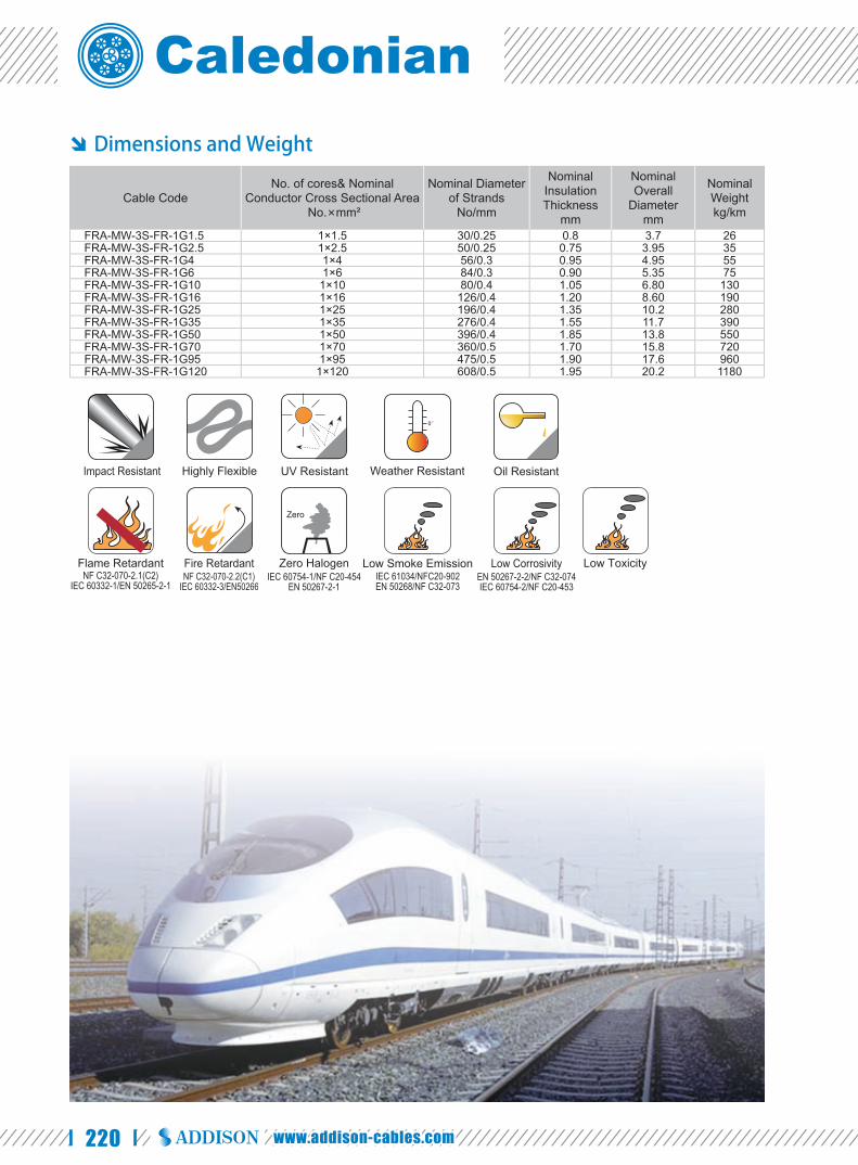
220 www.addison-cables.com
Dimensions and Weight
Cable CodeNo. of cores& Nominal
Conductor Cross Sectional Area No.×mm²
Nominal Diameter of Strands
No/mm
Nominal Insulation Thickness
mm
Nominal Overall
Diametermm
Nominal Weightkg/km
FRA-MW-3S-FR-1G1.5 1×1.5 30/0.25 0.8 3.7 26FRA-MW-3S-FR-1G2.5 1×2.5 50/0.25 0.75 3.95 35FRA-MW-3S-FR-1G4 1×4 56/0.3 0.95 4.95 55FRA-MW-3S-FR-1G6 1×6 84/0.3 0.90 5.35 75FRA-MW-3S-FR-1G10 1×10 80/0.4 1.05 6.80 130FRA-MW-3S-FR-1G16 1×16 126/0.4 1.20 8.60 190FRA-MW-3S-FR-1G25 1×25 196/0.4 1.35 10.2 280FRA-MW-3S-FR-1G35 1×35 276/0.4 1.55 11.7 390FRA-MW-3S-FR-1G50 1×50 396/0.4 1.85 13.8 550FRA-MW-3S-FR-1G70 1×70 360/0.5 1.70 15.8 720FRA-MW-3S-FR-1G95 1×95 475/0.5 1.90 17.6 960FRA-MW-3S-FR-1G120 1×120 608/0.5 1.95 20.2 1180
Impact Resistant Highly Flexible UV Resistant Weather Resistant Oil Resistant
Flame RetardantNF C32-070-2.1(C2)
IEC 60332-1/EN 50265-2-1NF C32-070-2.2(C1)
IEC 60332-3/EN50266
Fire Retardant Zero HalogenIEC 60754-1/NF C20-454
EN 50267-2-1
Zero
Low Smoke EmissionIEC 61034/NFC20-902EN 50268/NF C32-073
EN 50267-2-2/NF C32-074IEC 60754-2/NF C20-453
Low Corrosivity Low Toxicity

221
Caledonian Railway Cableswww.caledonian-cables.co.uk
FIRERAIL Databus Cables for Railway Applications
RAILDATA DATABUS CABLES FOR RAILWAY APPLICATIONS
RAILDATA DATABUS CABLES FOR RAILWAY APPLICATIONS
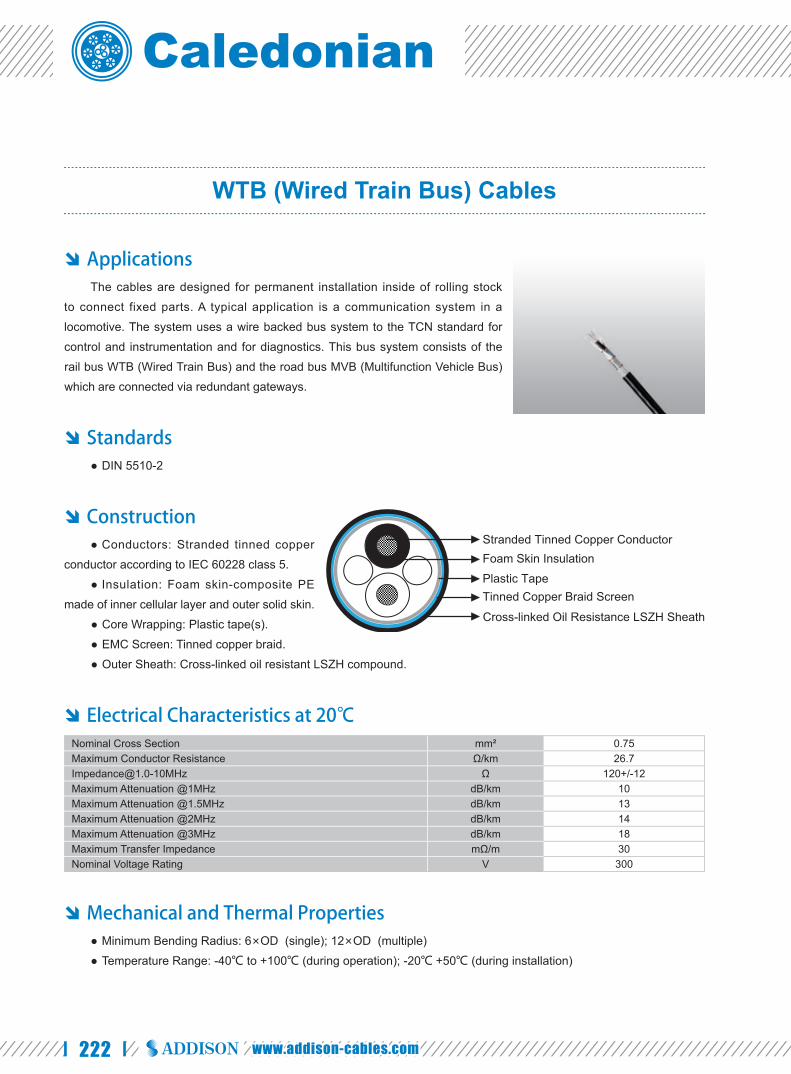
222 www.addison-cables.com
WTB (Wired Train Bus) Cables
Applications The cables are designed for permanent installation inside of rolling stock
to connect fixed parts. A typical application is a communication system in a
locomotive. The system uses a wire backed bus system to the TCN standard for
control and instrumentation and for diagnostics. This bus system consists of the
rail bus WTB (Wired Train Bus) and the road bus MVB (Multifunction Vehicle Bus)
which are connected via redundant gateways.
Standards DIN 5510-2 ●
Construction Conductors: Stranded tinned copper ●
conductor according to IEC 60228 class 5.
Insulation: Foam skin-composite PE ●
made of inner cellular layer and outer solid skin.
Core Wrapping: Plastic tape(s). ●
EMC Screen: Tinned copper braid. ●
Outer Sheath: Cross-linked oil resistant LSZH compound. ●
Electrical Characteristics at 20℃ Nominal Cross Section mm² 0.75Maximum Conductor Resistance Ω/km [email protected] Ω 120+/-12Maximum Attenuation @1MHz dB/km 10Maximum Attenuation @1.5MHz dB/km 13Maximum Attenuation @2MHz dB/km 14Maximum Attenuation @3MHz dB/km 18Maximum Transfer Impedance mΩ/m 30Nominal Voltage Rating V 300
Mechanical and Thermal Properties Minimum Bending Radius: 6×OD (single); 12×OD (multiple) ●
Temperature Range: -40℃ to +100℃ (during operation); -20℃ +50℃ (during installation) ●
Foam Skin InsulationStranded Tinned Copper Conductor
Plastic Tape
Cross-linked Oil Resistance LSZH Sheath
Tinned Copper Braid Screen

223
Caledonian Railway Cableswww.caledonian-cables.co.uk
Dimensions and Weight
Cable Code
No. of cores& Nominal Conductor Cross Sectional Area
No.×mm²
Nominal Diameter of
StrandsNo/mm
Nominal Sheath
Thicknessmm
Nominal Overall
Diametermm
Nominal Weightkg/km
RD-WTB-02YCH-2G0.75 2×0.75 19/0.22 1.4 8.3 97RD-WTB-02YCH-1P0.75S 1×2×0.75 19/0.22 1.4 9.0 110
Impact Resistant Highly Flexible UV Resistant Weather Resistant Oil Resistant
Flame RetardantNF C32-070-2.1(C2)
IEC 60332-1/EN 50265-2-1NF C32-070-2.2(C1)
IEC 60332-3/EN50266
Fire Retardant Zero HalogenIEC 60754-1/NF C20-454
EN 50267-2-1
Zero
Low Smoke EmissionIEC 61034/NFC20-902EN 50268/NF C32-073
EN 50267-2-2/NF C32-074IEC 60754-2/NF C20-453
Low Corrosivity Low Toxicity
FIRERAIL Databus Cables for Railway Applications
RAILDATA DATABUS CABLES FOR RAILWAY APPLICATIONS
RD-WTB-02YCH-2P0.75S 2×2×0.75 19/0.22 1.4 11.4 150

224 www.addison-cables.com
MVB (Multifunction Vehicle Bus) Cables
Applications The cables are designed for transmission of digital signals under baud rate
of 10M inside of rolling stock to connect fi xed parts. The communication system in
a locomotive uses a wire backed bus system to the TCN standard for control and
instrumentation and for diagnostics. This bus system consists of the rail bus WTB
(Wired Train Bus) and the road bus MVB (Multifunction Vehicle Bus) which are
connected via redundant gateways.
Standards DIN 5510-2 ●
Construction Conductors: Stranded tinned copper ●
conductor according to IEC 60228 class 5.
Insulation: Foam skin-composite PE ●
made of inner cellular layer and outer solid skin.
Core Wrapping: Plastic tape(s). ●
EMC Screen: Tinned copper braid. ●
Outer Sheath: Cross-linked oil resistant LSZH compound. ●
Electrical Characteristics at 20℃ Nominal Cross Section mm² 0.5Maximum Conductor Resistance Ω/km 41Impedance @0.5-2MHz Ω 120+/-12Maximum Attenuation @1MHz dB/km 12.5Maximum Attenuation @1.5MHz dB/km 15Maximum Attenuation @2MHz dB/km 18Maximum Attenuation @3MHz dB/km 21Maximum Transfer Impedance mΩ/m 20Nominal Voltage Rating V 300
Mechanical and Thermal Properties Minimum Bending Radius: 5×OD (single); 10×OD (multiple) ●
Temperature Range: -40℃ to +90℃ (during operation); -20℃ +50℃ (during installation) ●
Plastic Tape
Tinned Copper Braid Screen
Stranded Tinned Copper Conductor
Cross-linked Oil Resistance LSZH Sheath
Foam Skin Insulation

225
Caledonian Railway Cableswww.caledonian-cables.co.uk
Dimensions and Weight
Cable Code
No. of cores& Nominal Conductor Cross Sectional Area
No.×mm²
Nominal Diameter of
StrandsNo/mm
Nominal Sheath
Thicknessmm
Nominal Overall
Diametermm
Nominal Weightkg/km
RD-MVB-02YCH-1P0.5S+1G0.5 1×2×0.5+1×0.5 19/0.18 1.2 6.8 62RD-MVB-02YCH-2P0.5S 2×2×0.5 19/0.18 1.2 8.3 100
Impact Resistant Highly Flexible UV Resistant Weather Resistant Oil Resistant
Flame RetardantNF C32-070-2.1(C2)
IEC 60332-1/EN 50265-2-1NF C32-070-2.2(C1)
IEC 60332-3/EN50266
Fire Retardant Zero HalogenIEC 60754-1/NF C20-454
EN 50267-2-1
Zero
Low Smoke EmissionIEC 61034/NFC20-902EN 50268/NF C32-073
EN 50267-2-2/NF C32-074IEC 60754-2/NF C20-453
Low Corrosivity Low Toxicity
FIRERAIL Databus Cables for Railway Applications
RAILDATA DATABUS CABLES FOR RAILWAY APPLICATIONS

226 www.addison-cables.com
MVB (Multifunction Vehicle Bus) Cables (Redundant Version)
Applications The cables are designed for permanent installation inside of rolling stock
to connect fixed parts. A typical application is a communication system in a locomotive. The system uses a wire backed bus system to the TCN standard for control and instrumentation and for diagnostics. This bus system consists of the rail bus WTB (Wired Train Bus) and the road bus MVB (Multifunction Vehicle Bus) which are connected via redundant gateways.
Standards DIN 5510-2 ●
Construction Conductors: Stranded tinned copper ●
conductor according to IEC 60228 class 5. Insulation: 0.6mm foam/foam skin PE (for ●
0.5sqmm conductor), 0.2mm PE (for 0.25sqmm conductor). Core Wrapping: Plastic tape(s). ●EMC Screen: Tinned copper braid. ●Outer Sheath: Cross-linked oil resistant ●
LSZH compound.
Electrical Characteristics at 20℃ Nominal Cross Section mm² 0.5Maximum Conductor Resistance Ω/km 41Impedance @0.75-3MHz Ω 120+/-12Maximum Attenuation @1.5MHz dB/km 17Maximum Attenuation @3MHz dB/km 25Maximum Transfer Impedance mΩ/m 20Nominal Voltage Rating V 300
Mechanical and Thermal Properties Minimum Bending Radius: 6×OD (single); 10×OD (multiple) ●Temperature Range: -40℃ to +100℃ (during operation); -20℃ +50℃ (during installation) ●
Dimensions and Weight
Cable CodeNo. of cores& Nominal
Conductor Cross Sectional Area
No.×mm²
Nominal Diameter of
StrandsNo/mm
Nominal Sheath
Thicknessmm
Nominal Overall
Diametermm
Nominal Weightkg/km
RD-MVB-02YCH-1Q0.5S+4G0.25 1×4×0.5+4×1×0.25 19/0.18 0.6 7.9 95
Plastic Tape
Tinned Copper Braid Screen
Foam/ Foam-skin Insulation
Cross-linked Oil Resistance LSZH Sheath
Stranded Tinned Copper Conductor
Impact Resistant Highly Flexible UV Resistant Weather Resistant
Flame RetardantNF C32-070-2.1(C2)
IEC 60332-1/EN 50265-2-1NF C32-070-2.2(C1)
IEC 60332-3/EN50266
Fire Retardant Zero HalogenIEC 60754-1/NF C20-454
EN 50267-2-1
Zero
Low Smoke EmissionIEC 61034/NFC20-902EN 50268/NF C32-073
EN 50267-2-2/NF C32-074IEC 60754-2/NF C20-453
Low Corrosivity Low ToxicityOil Resistant
PE Insulation

227
Caledonian Railway Cableswww.caledonian-cables.co.uk
WTB (Wired Train Bus)/MVB (Multifunction Vehicle Bus) Cables
Applications The cables are used as connecting cables to transmit digital signals inside
railway rolling stocks. The communication system in a locomotive uses a wire
backed bus system to the TCN standard for control and instrumentation and for
diagnostics. This bus system consists of the rail bus WTB (Wired Train Bus) and
the road bus MVB (Multifunction Vehicle Bus) which are connected via redundant
gateways.
Standards DIN 5510-2 ●
Construction Conductors: Stranded tinned copper ●
conductor according to IEC 60228 class 5.
Insulation: Foam skin-composite PE ●
made of inner cellular layer and outer solid skin.
Cable Element: Twisted pair. ●
Core Wrapping: Plastic tape(s). ●
EMC Screen1: Aluminium clad polyester foil. ●
EMC Screen2: Tinned copper braid. ●
Core Wrapping: Plastic tape(s). ●
Outer Sheath: Cross-linked oil resistant LSZH compound. ●
Electrical Characteristics at 20℃ Nominal Cross Section/AWG mm² 0.62/20Maximum Conductor Resistance Ω/km 33.1Impedance @0.5-2MHz Ω 120+/-12Maximum Attenuation @1MHz dB/km 10Maximum Attenuation @2MHz dB/km 15Nominal Voltage Rating V 300
Mechanical and Thermal Properties Minimum Bending Radius: 6×OD (single); 12×OD (multiple) ●
Temperature Range: -40℃ to +100℃ (during operation); -20℃ +50℃ (during installation) ●
Aluminium Clad Polyester Foil Stranded Tinned Copper Conductor
Foam Skin Insulation
Plastic Tape
Tinned Copper Braid Screen
Plastic Tape
Cross-linked Oil Resistance LSZH Sheath
FIRERAIL Databus Cables for Railway Applications
RAILDATA DATABUS CABLES FOR RAILWAY APPLICATIONS

228 www.addison-cables.com
Dimensions and Weight
Cable Code
No. of cores& Nominal Conductor Cross Sectional Area
No.×mm²
Nominal Diameter of
StrandsNo/mm
Nominal Sheath
Thicknessmm
Nominal Overall
Diametermm
Nominal Weightkg/km
RD-WTB/MVB--02Y(ST+C)H-1P20A 1×2×0.62 19/0.2 1.2 8.3 80
Impact Resistant Highly Flexible UV Resistant Weather Resistant Oil Resistant
Flame RetardantNF C32-070-2.1(C2)
IEC 60332-1/EN 50265-2-1NF C32-070-2.2(C1)
IEC 60332-3/EN50266
Fire Retardant Zero HalogenIEC 60754-1/NF C20-454
EN 50267-2-1
Zero
Low Smoke EmissionIEC 61034/NFC20-902EN 50268/NF C32-073
EN 50267-2-2/NF C32-074IEC 60754-2/NF C20-453
Low Corrosivity Low Toxicity

229
Caledonian Railway Cableswww.caledonian-cables.co.uk
Integrated 9/11/18/20 Cores 0.75mm² UIC Databus Cables
Applications The cables are used as connecting cables to transmit digital signals inside
railway rolling stocks.
Standards DIN 5510-1 ●
Construction For 9 cores UIC databus cables:● 4 cores: 10 mm² stranded tinned
copper conductor with LSZH insulation. Combined Element: 3 cores (with ●
Cu-strand 2×6mm², 1×2.5mm²) are twisted with a fi lling element to a combined element. Wrapping: Overlapped plastic-foil(s). Elements sheaths: TPE
UIC Data Bus 0.75mm²: Two foam skin insulated tinned copper stranded conductors are twisted together with two ●fi lling elements to a pair.
Wrapping: Overlapped plastic-foil(s). Screen: Tinned copper wire braid screen Element sheaths: TPE. Wrapping: Overlapped plastic-foil(s).
Stranding: 4 strands are twisted to a core together with 3 cored element, the UIC data bus and two fi llers ●Core Wrapping: Overlapped plastic-foil(s). ●Outer Sheath: Cross-linked oil resistant LSZH compound. ●
For 11 cores UIC databus cables: 4 cores: 10 mm² stranded tinned ●
copper conductor with LSZH insulation.Combined Element: 5 cores (with ●
Cu-strand 2×6mm², 1×2.5mm² and 2×1.0 mm²) are twisted with a fi lling element to form a combined element.
Wrapping: Overlapped plastic-foil(s).Elements sheaths: TPE.
UIC Data Bus 0.75mm²: Two foam skin insulated tinned copper r stranded conductors are twisted together with ●two fi lling elements to a pair.
Wrapping: Overlapped plastic-foil(s). Screen: Tinned copper wire braid screen. Element sheaths: TPE. Wrapping: Overlapped plastic-foil(s).
Stranding: 4 strands are twisted to a core together with 5 cored element, the UIC data bus and two fi llers. ●Core Wrapping: Overlapped plastic-foil(s). ●Outer Sheath: Cross-linked oil resistant LSZH compound. ●
Plastic Foil(s)
Combined Element
4×10mm² with LSZH Insulation
Cross-linked LSZH Sheath
2×0.75mm² Data Bus with Foam Skin Insulation
Plastic Foil(s)
Combined Element
4×10mm² with LSZH Insulation
Cross-linked LSZH Sheath
2×0.75mm² Data Bus with Foam Skin Insulation
FIRERAIL Databus Cables for Railway Applications
RAILDATA DATABUS CABLES FOR RAILWAY APPLICATIONS

230 www.addison-cables.com
For 18/20 cores UIC databus cables: ● Star Quad: Four LSZH insulated
1mm² stranded tinned copper conductors are twisted to form a star quad.
UIC Data Bus 0.75mm²: Two foam ●skin insulated tinned copper stranded conductors are twisted together with two fi lling elements to form a pair.
Wrapping: Overlapped plastic-foil(s)Screen: Tinned copper wire braid screen Element sheaths: TPE. Wrapping: Overlapped plastic-foil(s)
Stranding: 4 star quads are stranded together with 2 or 4 UIC data bus cable and several fi llers. ●Core Wrapping: Overlapped plastic-foil(s). ●Screen: Tinned copper-wire braid screen. ●Outer Sheath: Cross-linked oil resistant LSZH compound. ●
Electrical Characteristics at 20℃ Nominal Cross Section mm² 0.75 1 2.5 6 10No of Strand/Strand Diameter 19/0.22 19/0.25 37/0.29 84/0.3 80/0.4Maximum Conductor Resistant Ω/km 26.7 20 8.21 3.39 [email protected] Ω 120+/-12 - - - -Maximum Attenuation @1MHz dB/km 10 - - - -Maximum Attenuation @1.5MHz dB/km 13 - - - -Maximum Attenuation @2MHz dB/km 14 - - - -Maximum Attenuation @3MHz dB/km 18 - - - -Maximum Transfer Impedance mΩ/m 30 - - - -Nominal Voltage Rating V 300 - - - -
Mechanical and Thermal Properties Minimum Bending Radius: 6×OD (single); 12×OD (multiple) ●Temperature Range: -40℃ to +90℃ (during operation); -20℃ +50℃ (during installation) ●
Dimensions and Weight
Cable CodeNo. of cores& Nominal Conductor
Cross Sectional Area No.×mm²
Nominal Sheath
Thicknessmm
Nominal Overall
Diametermm
Nominal Weightkg/km
RD-UIC-4C10S+2C6S+1C2.5S+2C0.75S 4×10+2×6+1×2.5+2×0.75 1.8 25 917RD-UIC-4C10S+2C6S+1C2.5S+2C1S+2C0.75S 4×10+2×6+1×2.5+2×1.0+2×0.75 1.8 25 969RD-UIC-4Q1S+2C0.75S 4×4×1.0+ 2×0.75 1.8 18.5 498RD-UIC-4Q1S+2P0.75S 4×4×1.0+ 2×2×0.75 1.8 23 530
Plastic Foil(s)
Tinned Copper Wire Braid Screen
Star Quad
Cross-linked LSZH Sheath
2×0.75mm² Data Bus with Foam Skin Insulation
Impact Resistant Highly Flexible UV Resistant Weather Resistant Oil Resistant
Flame RetardantNF C32-070-2.1(C2)
IEC 60332-1/EN 50265-2-1NF C32-070-2.2(C1)
IEC 60332-3/EN50266
Fire Retardant Zero HalogenIEC 60754-1/NF C20-454
EN 50267-2-1
Zero
Low Smoke EmissionIEC 61034/NFC20-902EN 50268/NF C32-073
EN 50267-2-2/NF C32-074IEC 60754-2/NF C20-453
Low Corrosivity Low Toxicity

231
Caledonian Railway Cableswww.caledonian-cables.co.uk
Category 5E Data Cables
Applications The cables are designed for permanently protected installation, inside and
outside railway rolling stock, buses and other vehicles to connect fixed parts.
Ethernet based networks as: infotainment, multimedia, passenger information
system etc.
Standards DIN 5510-2 ●EN 50228-2-2 ●BS 6853 ●EN 50306-3 par 4.8/4.9/4.10 ●
Construction For 4×0.5mm², 4×22AWG cables:● Conductors: Stranded tin plated
copper conductor (for 0.5mm² cables) or stranded silver plated copper conductor (for 22AWG cables) according to IEC 60228 class 5.
Insulation: Electron beam crosslinkable compound. ●Cable Element: Individual conductor stranded together. ●EMC Screen1: Plastic laminated aluminium-tape. ●EMC Screen2: Tinned copper braid. ●Separator (s): Plastic tape. ●Outer Sheath: Electron beam crosslinkable compound. ●
For 4×2×22AWG cables: ● Center: PE fi ller.
4 pairs 2×22AWG: Stranded tinned copper conductor according to IEC 60228 class 5. ●Insulation: Electron beam crosslinkable compound. ●EMC Screen1: Plastic laminated aluminium-tape. ●EMC Screen2: Tinned copper braid. ●Separator(s): Plastic tape. ●Outer Sheath: Electron beam crosslinkable compound. ●
Plastic Laminated Aluminium-tape
Electron Beam Crosslinkable LSZH Insulation
Stranded Tin/Silver Plated Copper Conductor
Plastic Tape
Electron Beam Crosslinkable LSZH Sheath
Tin Plated Copper Braid
FIRERAIL Databus Cables for Railway Applications
RAILDATA DATABUS CABLES FOR RAILWAY APPLICATIONS

232 www.addison-cables.com
Electrical Characteristics at 20℃ Nominal Cross Section mm² 0.5 -AWG - 22Nominal Conductor Resistance Ω/km 40.1 54.4Maximum Resistance Unbalance Ω/km 1.1 1.1Maximum Capacitance
Core to Core pF/m 65 65Core to Screen pF/m 100 100
Characteristic Impedance @100MHz Ω 100+/-5 100+/-5Transfer Impedance f≤30MHz mΩ/m 200 200Nominal Voltage Rating V 300 300
Mechanical and Thermal Properties Minimum Bending Radius: 6×OD ●
Temperature Range: -40℃ to +90℃ ●
Dimensions and Weight
Cable CodeNo. of cores& Nominal Conductor
Cross Sectional Area No.×mm²
Nominal Diameter of
StrandsNo/mm
Nominal Sheath
Thicknessmm
Nominal Overall
Diametermm
Nominal Weightkg/km
RD-Cat5E-4C0.5S 4×0.5 19/0.18 1.2 8.3 102RD-Cat5E-4C22A 4×22AWG 19/0.16 1.2 7.25 81RD-Cat5E-4P22A 4×2×22AWG 19/0.16 1.2 12.6 174
Impact Resistant Highly Flexible UV Resistant Weather Resistant Oil Resistant
Flame RetardantNF C32-070-2.1(C2)
IEC 60332-1/EN 50265-2-1NF C32-070-2.2(C1)
IEC 60332-3/EN50266
Fire Retardant Zero HalogenIEC 60754-1/NF C20-454
EN 50267-2-1
Zero
Low Smoke EmissionIEC 61034/NFC20-902EN 50268/NF C32-073
EN 50267-2-2/NF C32-074IEC 60754-2/NF C20-453
Low Corrosivity Low Toxicity
233
Caledonian Railway Cableswww.caledonian-cables.co.uk
ORDERING INFORMATION
ORDERING INFORMATION
ORDERING INFORMATION

234 www.addison-cables.com
Ordering Code for Railway Signalling Cables ( RAILSIG Series)
RSA/B-CDEFGHIJ-K-LMNO
A. Design Standard
107y: DLK 1.013.107y Standard
108y: DLK 1.013.108y Standard
109y: DLK 1.013.109y Standard
110y: DLK 1.013.110y Standard
00014: NR/PS/TEL/00014 Standard ( formerly RT/E/PS/00014)
27220: NR/PS/ELP/27220 Standard ( formerly RT/E/PS/0034)
1932: BR1932 Standard
7621A2/T1: LUL G7621 A2 Type 1 Standard (for PVC Sheath)
7621A2/T2: LUL G7621 A2 Type 2 Standard (for LSZH Sheath)
7622A1/T1: LUL G7622 A1 Type 1 Standard (for PVC Sheath)
7622A1/T2: LUL G7622 A1 Type 2 Standard (for LSZH Sheath)
7623A2: LUL G7623 A2 Standard
2029: TR2029 Standard
B Basic Type
A-: Outdoor Cables
AJ-: Outdoor Cables with inductive protection
CV: Unsheathed Board Wiring Cables (French RATP RATP Railway Standard)
CV-S: Unsheathed Flexible Board Wiring Cables (French RATP Railway Standard)
CVZ: Sheathed Board Wiring Cables (French RATP Railway Standard)
CVZ-S: Sheathed Flexible Board Wiring Cables (French RATP Railway Standard)
ZUG: Multipair Internal Equipment Cables (French RATP Railway Standard)
ZUT: Multipair Screened Internal Equipment Cables (French RATP Railway Standard)
SUG: Multicore Internal Equipment Cables (French RATP Railway Standard)
SCG: Local Control Cables (French RATP Railway Standard)
A1: Unsheathed EPR/LSZH Insulated Railway Signalling Cables (UK NETWORK RAIL Standard)
A2: EPR/LSZH Insulated & LSZH Sheathed Single Core Railway Signalling Cables (UK NETWORK RAIL Standard)
A3: EPR/LSZH Insulated & LSZH Sheathed Multicore Railway Signalling Cables (UK NETWORK RAIL Standard)
B1: EPR Insulated & HDPCP Sheathed Single Core Class 2 Stranded Railway Signalling Cables (UK NETWORK RAIL
Standard)
B2: EPR Insulated & HDPCP Sheathed Multicore Class 2 Stranded Railway Signalling Cables (UK NETWORK RAIL
Standard)
C1: EPR Insulated & HDPCP Sheathed Single Core Class 5 Stranded Railway Signalling Cables (UK NETWORK
RAIL Standard)

235
Caledonian Railway Cableswww.caledonian-cables.co.uk
C2: EPR Insulated & HDPCP Sheathed Multicore Class 5 Stranded Railway Signalling Cables (UK NETWORK RAIL
Standard)
C3: EPR Insulated & HDPCP Sheathed Single Pair Screened Class 5 Stranded Railway Signalling Cables (UK
NETWORK RAIL Standard)
D1: EPR/LSZH Insulated & LSFROH Sheathed Single Core Class 2 Stranded Railway Signalling Cables (UK
NETWORK RAIL Standard)
D2: EPR/LSZH Insulated & LSZH Sheathed Multicore Class 2 Stranded Railway Signalling Cables (UK NETWORK
RAIL Standard)
E1: EPR/LSZH Insulated & LSZH Sheathed Single Core Class 5 Stranded Railway Signalling Cables (UK
NETWORK RAIL Standard)
E2: EPR/LSZH Insulated & LSZH Sheathed Multicore Class 5 Stranded Railway Signalling Cables (UK NETWORK
RAIL Standard)
EAPSP: Steel Tape Armoured Railway Signalling Cables (Spainish RENFE Railway Standard)
EAPSP-R: Steel Tape Armoured Jelly Filled Railway Signalling Cables (Spainish RENFE Railway Standard)
CCPSSP-FR0.3: Anti Induction PE Sheathed Railway Signalling Cables with Reduction Factor 0.3 (Spainish RENFE
Railway Standard)
CCPSSP-FR0.1: Anti Induction PE Sheathed Railway Signalling Cables with Reduction Factor 0.1 (Spainish RENFE
Railway Standard)
CCPSSP-R-FR0.1: Anti Induction PE Sheathed Jelly Filled Railway Signalling Cables with Reduction Factor 0.1
(Spainish RENFE Railway Standard)
CCTSST-FR0.1: Anti Induction FRNC-PE Sheathed Railway Signalling Cables with Reduction Factor 0.1 (Spainish
RENFE Railway Standard)
CCTSST-FR0.3: Anti Induction FRNC-PE Sheathed Railway Signalling Cables with Reduction Factor 0.3 (Spainish
RENFE Railway Standard)
ZPAU: Anti Induction PE Sheathed Copper Tape Screened Multipair Railway Signalling Cables (French RATP
Railway Standard)
ZPFU: Anti Induction PE Sheathed Unscreened Multipair Railway Signalling Cables (French RATP Railway
Standard)
ZPGU: PE Sheathed Multipair Railway Signalling Cables (French RATP Railway Standard)
ZCO3: Anti Induction PE Sheathed Multiquad Railway Signalling Cables (French RATP Railway Standard)
K23: Anti Induction LSZH Sheathed Multiquad Subway Signalling Cables (French RATP Railway Standard)
K24: LSZH Sheathed Multipair LSZH Sublway Signalling Cables (French RATP Railway Standard)
K13: PVC Sheathed Multipair LSZH Sublway Signalling Cables (French RATP Railway Standard)
DIG: Digicode 30KHz Indoor Signalling Cables ( French RATP Railway Standard)
SXCAV & SXCAG: Switching Centre Signalling Cables ( Belgium SNCB Railway Standard)
SW: Switching Centre Signalling Cables (Swiss SBB Railway Standard)
RT/F3-D type: Unarmoured PE/LSZH Sheathed Axle Counter Cables (UK NETWORK RAIL Standard)
RT/F3-S type: Steel Tape Armoured PE/LSZH Sheathed Axle Counter Cables (UK NETWORK RAIL Standard)
RT/F3-B type: Brass Tape Armoured PE/LSZH Sheathed Axle Counter Cables (UK NETWORK RAIL Standard)
RT/F3-R type: Ruggedised PE Sheahed Axle Counter Cables (UK NETWORK RAIL Standard)
RT/F3-S/E1: PE/LSZH Sheathed Axle Counter Cables Reduction Factor 0.65 (UK NETWORK RAIL Standard)
RT/F3-S/E2: PE/LSZH Sheathed Axle Counter Cables Reduction Factor 0.45 (UK NETWORK RAIL Standard)
RT/F3-S/E3: PE/LSZH Sheathed Axle Counter Cables Reduction Factor 0.2(UK NETWORK RAIL Standard)
SPFB: Speed Control System Balise Cables (French KVB System)
SIF: Speed Control Eurobalise Cables (European ERTMS System)
ORDERING INFORMATION
ORDERING INFORMATION

236 www.addison-cables.com
BGA: Speed Control Eurobalise Cables (European
ERTMS System)
K27: Fire Resistant Silicon Rubber Insulated LSZH
Sheathed Signalling Cables
MD4: Fire Resistant Mica Tape Insulated LSZH
Sheathed Railway Signalling Cables
RT/ZHLS: LSZH Sheathed Trackside Telephone Cables
C Insulation
02Y: Cellular PE
2Y: Solid PE
02YS: Foam Skin (Cellular / Solid PE Dual Layer)
Y: PVC
2G: Silicone Rubber
3G: EPR
H: LSZH
D Filling
(F): Petroleum Jelly Filling
Blank: Unfi lled
E Screening
(St): Static shield of plastic-backed aluminium tape
Blank: No screen
F Bedding
2Y: PE
Y: PVC
H: LSZH
(L)2Y: Aluminium/PE Laminated sheath
Blank: No Inner Sheath
G Electrostatic Shield
D: Copper wire concentric screen
(K): Copper tape screen
C: Copper wire braid screen
(…Cu): Total cross section of copper shield in mm²
H Electromagnetic Shield
B: Single / Double layer of Galvanised Steel Tape
Armor
(1B… 0.5): One Layer of Helically Applied Steel Tape,
thickness of Steel Tape in 0.5 mm.
(1B… 0.8): One Layer of Helically Applied Steel Tape,
thickness of Steel Tape in 0.8 mm.
(2B… 0.5): Two Layers of Helically Applied Steel
Tape, thickness of Steel Tape in 0.5 mm.
(2B… 0.8): Two Layers of Helically Applied Steel
Tape, thickness of Steel Tape in 0.8 mm.
I Armoring
b: Steel Tape Armoring
SR- Corrugated Steel Tape Armouring
Blank: No Armour
J Sheath
2Y: PE
2Yv: Reinforced PE Sheath
Y: PVC
H: LSZH
Hv: Reinforced LSZH Sheath
5G: HDPCP
4Y: PA Sheath
K No of Cores/ Pairs/Quads×Conductor Diameter
/ Number of Cores/Pairs/Quads×Cross Section
NC0.9: N Cores×0.9mm
NC1.4: N Cores×1.4mm
NC1.8: N Cores×1.8mm
NP0.9: N Pairs×0.9mm
NP1.4: N Pairs×1.4mm
NP1.8: N Pairs×1.8mm
NQ0.9: N Quads×0.9mm
NQ1.4: N Quads×1.4mm
NQ1.8: N Quads×1.8mm
NC0.5S: N Cores×0.5 mm²
NP1.0S: N Pairs×1.0 mm²
NQ1.5S: N Quads×1.5 mm²
NG0.5: N Cores×0.5 mm²

237
Caledonian Railway Cableswww.caledonian-cables.co.uk
L Cable Category
S- Signal Cables
M Types of Stranding
Bd: Twisted in layers
Lg: Twisted in units
N Operating Capacity / Mutual Capacitance
H145: Mutual Capacitance of 145nF/Km
H115: Mutual Capacitance of 115nF/Km
H95: Mutual Capacitance of 95nF/Km
H45: Mutual Capacitance of 45nF/Km
O Reduction Factor
R4: R401 Series (Reduction Factor 0.15)
R5: R501 Series (Reduction Factor 0.35)
R6: R601 Series (Reduction Factor 0.55)
P Fire Retardance & Resistance Options
I1: Fire propagation to IEC 60332-1
I3C: Fire propagation to IEC 60332-3C
E30: 30 mins Circuit integrity according to DIN 4102
Part 12
E60: 60 mins Circuit integrity according to DIN 4102
Part 12
E180: 180 mins Circuit integrity according to DIN
4102 Part 12
B6387CWZ: BS 6387 CWZ
Ordering Code for Railway Control & Power Cables (RAILFEEDER Series)
RFA/B-C-DEFG-HI-J
A. Design Standard
55625: NF F 55-625 Standard
21101: RT/E/S/21101 Standard
14025: EME-SP-14-025 / SE908Standard
14026: EME-SP-14-026 Standard
14027: EME-SP-14-027 Standard
14028: EME-SP-14-028 Standard
260: SE260 Standard
774: SE774 Standard
895: SE895 Standard
902: SE902 Standard
1047: SE1047 Standard
LU12: LU Section 12 Standard
880: BR880 Standard
40045: NR/S/ELP/40045 Standard
00008: NR/PS/ELP/00008 Standard
7835: BS 7835 Standard
6622: BS 6622 Standard
7655: BS 7655 Standard
31102: NR/PS/TEL/31102 (BR1817) Standard
ORDERING INFORMATION
ORDERING INFORMATION

238 www.addison-cables.com
B. Basic Types
K25: Class 2 plain copper conductor to IEC 60228, XLPE Insulated, steel tape armoured and low smoke halogen
free polyolefi n sheathed trackfeeder cables
NSGAFOU: Single Core EPR insulated and PCP sheathed cable
H07RN-F: 450/750V EPR insulated and PCP sheathed cables
H01N2-D: 450/750V CSP sheathed welding cables, HOFR, heat resistant, oil resistant and fl ame retardant
VV-U: Class 2 plain copper conductor to IEC 60228, PVC insulated and PVC sheathed cables
VV-K: Class 5 fl exible plain copper conductor to IEC 60228, PVC insulated and PVC sheathed cables
Z1Z1-U: Class 2 plain copper conductor to IEC 60228, low smoke halogen free polyolefi n insulated and low smoke
halogen free polyolefi n sheathed cables
Z1Z1-K: Class 5 fl exible plain copper conductor to IEC 60228, low smoke halogen free polyolefi n insulated and low
smoke halogen free polyolefi n sheathed cables
RZ1-U(AS): Class 2 plain copper conductor to IEC 60228, XLPE insulated and low smoke halogen free polyolefi n
sheathed safety cables
RZ1-K(AS): Class 5 flexible plain copper conductor to IEC 60228, XLPE insulated and low smoke halogen free
polyolefi n sheathed safety cables
ES07Z-U(AS): 450/750V Class 2 plain copper conductor to IEC 60228, low smoke halogen free polyolefi n insulated
safety cables, unsheathed
ES07Z-K(AS): 450/750V Class 5 fl exible plain copper conductor to IEC 60228, low smoke halogen free polyolefi n
insulated safety cables, unsheathed.
DZ1-U(AS): Class 2 plain copper conductor to IEC 60228, EPR insulated and low smoke halogen free polyolefi n
sheathed safety cables
DZ1-K(AS): Class 5 flexible plain copper conductor to IEC 60228, EPR insulated and low smoke halogen free
polyolefi n sheathed safety cables.
DOZ1-U(AS): Class 2 plain copper conductor to IEC 60228, EPR insulated, aluminum/polyester tape screened and
low smoke halogen free polyolefi n sheathed high safety cables
DOZ1-K(AS): Class 5 flexible plain copper conductor to IEC 60228, EPR insulated , aluminum/polyester tape
screened and low smoke halogen free polyolefi n sheathed high safety cables
SZ1-U(AS+): Class 2 plain copper conductor to IEC 60228, silicon rubber insulated and low smoke halogen free
polyolefi n sheathed high safety cables
SZ1-K(AS+): Class 5 fl exible plain copper conductor to IEC 60228, silicon rubber insulated and low smoke halogen
free polyolefi n sheathed high safety cables.
SOZ1-U PH90 (AS+): Class 2 plain copper conductor to IEC 60228, silicon rubber insulated, aluminum/polyester
tape screened and low smoke halogen free polyolefi n sheathed high safety cables with fi re resistance to EN 50200 PH 90
SOZ1-K PH 90 (AS+): Class 5 fl exible plain copper conductor to IEC 60228, silicon rubber insulated , aluminum/
polyester tape screened and low smoke halogen free polyolefi n sheathed high safety cables with fi re resistance to EN
50200 PH 90
MICC: Solid plain annealed copper, magnesium oxide insulated and copper sheathed fi re resistant cables.
RZ1MZ1-U (AS): Class 2 plain copper conductor to IEC 60228, XLPE Insulated. steel wire armoured and low smoke
halogen free polyolefi n sheathed safety cables
RZ1MZ1-K(AS): Class 5 fl exible plain copper conductor to IEC 60228, XLPE Insulated, steel wire armoured and low
smoke halogen free polyolefi n sheathed safety cables
RZ1MZ1-U MICA (AS+): Class 2 plain copper conductor to IEC 60228, MICA/XLPE Insulated., steel wire armoured
and low smoke halogen free polyolefi n sheathed safety cables

239
Caledonian Railway Cableswww.caledonian-cables.co.uk
RZ1MZ1-K MICA (AS+): Class 5 fl exible plain copper conductor to IEC 60228, MICA/XLPE Insulated, steel wire
armoured and low smoke halogen free polyolefi n sheathed safety cables
RZ1F3Z1-U(AS): Class 2 plain copper conductor to IEC 60228, XLPE Insulated, steel tape armoured and low
smoke halogen free polyolefi n sheathed safety cables
RZ1F3Z1-K(AS): Class 5 fl exible plain copper conductor to IEC 60228, XLPE Insulated, .steel tape armoured and
low smoke halogen free polyolefi n sheathed safety cables
VC4VV-U: Class 2 plain copper conductor to IEC 60228, PVC insulated, copper wire braided, PVC inner sheathed
and PVC over sheathed concentric cables
RC4Z1Z1-U: Class 2 plain copper conductor to IEC 60228, XLPE insulated, copper wire braided, low smoke
halogen free polyolefi n inner sheathed and low smoke halogen free polyolefi n over sheathed concentric cables
VC4VC4V-U: Class 2 plain copper conductor to IEC 60228, PVC insulated, copper wire spiral screened, PVC inner
sheathed, copper wire braided and PVC over sheathed concentric cables
RC4Z1C4Z1-U: Class 2 plain copper conductor to IEC 60228, XLPE insulated, copper wire spiral screened, low
smoke halogen free polyolefi n inner sheathed, copper wire braided and low smoke halogen free polyolefi n over sheathed
concentric cables
RHZ1 H16- Class 2 plain copper conductor to IEC 60228, semi conducting conductor screen, XLPE insulated, semi
conducting insulation screen, copper wire + copper tape screened and low smoke halogen free polyolefin sheathed
medium voltage cables
RHZ1MZ1: Class 2 plain copper conductor to IEC 60228, semi conducting conductor screen, XLPE insulated,
semi conducting insulation screen, individual and overall copper tape screened, low smoke halogen free polyolefi n inner
sheathed, steel wire armoured and low smoke halogen free polyolefi n sheathed medium voltage cables
RHVMV: Class 2 plain copper conductor to IEC 60228, semi conducting conductor screen, XLPE insulated, semi
conducting insulation screen, individual and overall copper tape screened, PVC inner sheathed, steel wire armoured and
PVC sheathed medium voltage cables
XKDT: Class 2 plain copper conductor to IEC 60228, semi conducting conductor screen, XLPE insulated, semi
conducting insulation screen, copper wire screened, longitudinal watertight and PE sheathed medium voltage cables
XKDT-YT: Class 2 plain copper conductor to IEC 60228, semi conducting conductor screen, XLPE insulated, semi
conducting insulation screen, three twisted single core, copper wire screened, longitudinal watertight and HDPE sheathed
medium voltage cables
XKDT-FT: Class 2 plain copper conductor to IEC 60228, semi conducting conductor screen, XLPE insulated, semi
conducting insulation screen, three twisted single core, copper wire screened, galvanized steel flat wire armoured,
longitudinal watertight and PE sheathed medium voltage cables
C Voltage Rating
300/500V: 300/500V; 450/750V-450/750V; 0.6/1KV: 600/1000V; 300N-300V DC Negative; 1800P-1800V DC
Positive
6.35/11KV: 6.35/11KV; 19/33KV-19/33KV
H: No of Cores×Conductor Diameter / Number of Cores×Cross Section
3G0.5: 3 Cores×0.5mm²
ORDERING INFORMATION
ORDERING INFORMATION

240 www.addison-cables.com
I Conductor Type
AL: Aluminium CU: Copper
J Fire Retardance & Resistance Options
FR: Fire Resistant
I1: Fire propagation to IEC 60332-1
I3C: Fire propagation to IEC 60332-3C
E30: 30 mins Circuit integrity according to DIN 4102 Part 12
E60: 60 mins Circuit integrity according to DIN 4102 Part 12
E180: 180 mins Circuit integrity according to DIN 4102 Part 12
B6387CWZ: BS 6387 CWZ
Ordering Code for Railway Traction Cables (FIRERAIL Series)
FRA-A-BC-D-E-F-G
A Wall Type
SW: Standard Wall
MW: Medium Wall
TW: Thin Wall
HT: High Temperature
B Voltage Type
0.5: 300/500V
1: 0.6/1KV
3: 1.8/3KV
6: 3.6/6KV
C Core Type
S: Single Core
M: Multi Core
MP: Multi Pair
D Insulation or Sheath Type
U: Unsheathed
SW: Standard Wall Sheath
ESW: Exposed Standard Wall Sheath
RI: Reinforced Insulation
E Screen Type
OS: Overall Screen
IOS: Individual & Overall Screen
F Number of Cores and Pairs
10G: 10 Cores
G: Cross Section Areas
1.5: 1.5mm²

241
Caledonian Railway Cableswww.caledonian-cables.co.uk
Ordering Code for Railway Fiber Optic Cables (RAILOPTICS Series)
Central Loose Tube Cable
RO/A-CL-B-C-D-E-F-G-H-I-J-K
A; Cable Category
K209A/B: Railway Fiber Optic Cables
2328: SNCF CT2328 / SNCT CT 2329
2513: SNCF CT2513-99 / SNCT CT 2513-99
2242: SNCF CT2242.6.1
B: Loose tube diameter
A=2.1mm, B=2.5mm
C: Fiber type
0=Fiber and copper conductors in cable
4=50/125 multi-mode fi ber (OM3) per ITU-T G.651
5=50/125 multi-mode fi ber (OM2) per ITU-T G.651
6=62.5/125 multi-mode fi ber (OM1) per ITU-T G.651
7=NZDS SM fi ber per ITU-T G.656.
8=NZDS SM fi ber per ITU-T G.655.
9=Standard SM fi ber per ITU-T G.652.D
Ended with R=Ribbon type fi ber ( Ex: 9R= SM fi ber
per G.652.D ribbon type )
D: No. of fibers: 1 to 24
E: Bedding
2Y=PE, Y=PVC, H=LSZH
F: Armour
Blank=No armour, T=Corrugated steel tape armour,
W=Steel wire armour
B=Bronze armour, D=Fiber glass armour; TW= Steel
tape + Steel wire armour
G: Sheath
2Y=PE, Y=PVC, H=LSZH, 11Y=PU, A=Aluminium
moisture barrier,
T=Anti-termite protection
H: Water-blocking options for cable core
X=No water-blocking; J= Water blocking gel in tubes;
JD=Water-blocking gel in tubes + dry water blocking
in cable core interstices;
JJ= Water-blocking gel in tubes and cable core
interstices.
I: Water-blocking options for cables with
more than one jacket
X=No water-blocking, J= Water blocking gel between
jackets;
D=Dry water-blocking between cable jackets;
J: Strength member
A=Aramid yarn, AG=Aramid yarn and fi berglass yarn,
G=Fiberglass yarn
K: General options
SS=Fig-8 self-supporting
ORDERING INFORMATION
ORDERING INFORMATION

242 www.addison-cables.com
Multi Loose Tube Cable
RO/A-ML-B-C-DxE-F-G-H-IJ-K-L-M
A; Cable Category
K209A/B: Railway Fiber Optic Cables
2328: SNCF CT2328 / SNCT CT 2329
2513: SNCF CT2513-99 / SNCT CT 2513-99
2242: SNCF CT2242.6.1
B: Loose tube diameter
B=2.1mm, C=2.5mm, D=2.8mm, E=3.0mm, F=3.2mm
C: Fiber type
0=Fiber and copper conductors in cable
4=50/125 multi-mode fi ber (OM3) per ITU-T G.651
5=50/125 multi-mode fi ber (OM2) per ITU-T G.651
6=62.5/125 multi-mode fi ber (OM1) per ITU-T G.651
7=NZDS SM fi ber per ITU-T G.656.
8=NZDS SM fi ber per ITU-T G.655.
9=Standard SM fi ber per ITU-T G.652.D
Ended with R=Ribbon type fi ber ( Ex: 9R= SM fi ber
per G.652.D ribbon type )
D: No. of tubes: 1 to 36
E: No. of fibers per tubes: 2 to 12
F: Central member
S=Sol id s tee l , SR=Stranded stee l , F=Fiber
Reinforced Plastic (FRP)
G: Bedding
2Y=PE, Y=PVC, H=LSZH
H: Armour
Blank=No armour, STA=Corrugated steel tape
armour, SWA=Steel wire armour
B=Bronze armour, F=Fiber glass armour; TW= Steel
tape + Steel wire armour
I: Sheath
2Y=PE, Y=PVC, H=LSZH,
11Y=PU, A=Aluminium moisture barrier, T=Anti-
termite protection
J: Water-blocking options for cable core
X=No water-blocking; J= Water blocking gel in tubes;
JD=Water-blocking gel in tubes + dry water blocking
in cable core interstices;
JJ= Water-blocking gel in tubes and cable core
interstices.
K: Water-blocking options for cables with more than one jacket
X=No water-blocking, J= Water blocking gel between
jackets;
D=Dry water-blocking between cable jackets;
L: Strength member
A=Aramid yarn, AG=Aramid yarn and fi berglass yarn,
G=Fiberlass yarn
M: General options
SS=Fig-8 self-supporting

243
Caledonian Railway Cableswww.caledonian-cables.co.uk
Ordering Code for Railway Coaxial Cables (RAILCOX Series)
RS/A-B
A Basic Type
K26: 50/75Ω Coaxial Cables
B Cable Category
HCAAYZ-50-6 (1/4”): Copper clad aluminium or copper (inner conductor) + annular corrugated copper tube (outer
conductor) 50Ω 1/4” foam dielectric fl exible feeder coaxial cable
HCAAYZ-50-8 (3/8”): Copper clad aluminium or copper (inner conductor) + annular corrugated copper tube (outer
conductor) 50Ω 3/8” foam dielectric fl exible feeder coaxial cable
HCAAYZ-50-12 (1/2”): Copper clad aluminium (inner conductor) + annular corrugated copper tube (outer
conductor) 50Ω 1/2” foam dielectric fl exible feeder coaxial cable
HCTAYZ-50-22 (7/8”): Copper tube (inner conductor) + annular corrugated copper tube (outer conductor) 50Ω 7/8”
foam dielectric fl exible feeder coaxial cable
HCTAYZ-50-32 (1'1/4): Copper tube (inner conductor) + annular corrugated copper tube (outer conductor) 50Ω 1'1/4
foam dielectric fl exible feeder coaxial cable
HHTAYZ-50-42 (1'5/8): Helical corrugated copper tube (inner conductor) + annular corrugated copper tube (outer
conductor) 50Ω 1'5/8 foam dielectric fl exible feeder coaxial cable
HRYZ-50-5 (1/4"SF): Copper wire (inner conductor) + helical corrugated copper tube (outer conductor) 50Ω 1/4”
foam dielectric super fl exible feeder coaxial cable
HRCAYZ-50-7 (3/8”SF): Copper clad aluminium or copper (inner conductor) + helical corrugated copper tube (outer
conductor) 50Ω 3/8” foam dielectric super fl exible feeder coaxial cable
HRCAYZ-50-9 (1/2”SF): Copper clad aluminium (inner conductor) + helical corrugated copper tube (outer
conductor) 50Ω 1/2” foam dielectric super fl exible feeder coaxial cable
HRCTYZ-50-22 (7/8”SF): Copper tube (inner conductor) + helical corrugated copper tube (outer conductor) 50Ω
7/8” foam dielectric super fl exible feeder coaxial cable
HRYZ-50-5 (1/4”XF): Copper wire (inner conductor) + helical corrugated copper tube (outer conductor) 50Ω 1/4”
foam dielectric extra fl exible feeder coaxial cable
HRCAYZ-50-7 (3/8”XF): Copper clad aluminium or copper (inner conductor) + helical corrugated copper tube (outer
conductor) 50Ω 3/8” foam dielectric extra fl exible feeder coaxial cable
ORDERING INFORMATION
ORDERING INFORMATION

244 www.addison-cables.com
Ordering Code Railway Databus Cables (RAILDATA Series)
RD-A-BC-DEFGH
A Basic Type
L120: Railway F/FTP Data Cables
K20: Steel Wire Braided Railway F/FTP Data Cables
WTB: Wired Train Bus
MVB: Multifunction Vehicle Bus
B Construction Type
F/UTP: Overall Aluminium/Polyester Screening
F/FTP: Individual Aluminium/Polyester Screening +
Overall Aluminium/Polyester Screening
U/FTP: Individual Aluminium/Polyester Screening
C Cable Category
Cat5E: Cat 5E Type
Cat6: Cat6 Type
Cat6A: Cat 6A Type
RS485: RS 485 Type
D Insulation
02Y: Cellular PE
2Y: Solid PE
02YS: Foam Skin (Cellular / Solid PE Dual Layer)
E Screening Material
(St): Overall Shielded with Aluminium/Polyester Tape
Shielded
C: Overall Shielded with Copper Wire Braid
PiC: Pairs Shielded with Copper Wire Braid
PiMF: Pairs Shielded with Aluminium/polyester Tape
F Armoring
SWB: Steel Wire Braid Armoring
SWA: Steel Wire Armoring
STA: Steel Tape Armoring
Blank: No Armour
G Sheath
2Y: PE
Y: PVC
H: LSZH
H No of Pairs×Conductor Diameter
4P0.56: 4 Pairs×0.56mm
4P0.6: 4 Pairs×0.6mm

UNITED KINGDOM
Marchants Industrial Centre, Mill Lane, Laughton, Lewes,East Sussex, BN8 6AJ, UKTe l: 44-207-4195087Fax: 44-207-8319489Email: [email protected]: www.caledonian-cables.co.uk
HONG KONG
Unit B 22/F CMA Building 64-66 Connaught Road CentralHong KongTe l: 852-36527508Fax: 852-35834834Email: [email protected] [email protected]
SHANGHAI
Room 3501, CITIC Square, 1168 Nanjing Xi Lu,Shanghai 200041, P.R. ChinaTe l: 86-21-51119178Fax: 86-21-52524616Email: [email protected] [email protected]