calcasieu river and pass dredged material sedimentation study · calcasieu river and pass dredged...
TRANSCRIPT

________________________________
CALCASIEU RIVER AND PASS DREDGED MATERIAL SEDIMENTATION STUDY May 2004 Final Report by Environmental Processes and Engineering Division Environmental Laboratory U.S. Army Engineer Research and Development Center Waterways Experiment Station 3909 Halls Ferry Road Vicksburg, MS Prepared for U.S. Army Engineer District, New Orleans New Orleans, LA
i
Contents 1 Introduction ..................................................................................... 1 Background ............................................................................................. 1 Purpose ................................................................................................... 1 Objectives ............................................................................................... 1 2 Column Settling Test Procedures .................................................... 2 Experimental Procedures ........................................................................ 2 Sample collection ............................................................................... 8 Settling tests ....................................................................................... 8 Laboratory Procedures ............................................................................ 8 Slurry preparation .............................................................................. 8 Zone settling test ................................................................................ 8 Compression settling test ................................................................... 10 Flocculent settling test ....................................................................... 11 3 Data Analysis and Results ............................................................... 11 Data Adjustment………………………………………………………. 11 Compression Settling Test ...................................................................... 13 Zone Settling Test ................................................................................... 13 Flocculent Settling Test .......................................................................... 15 Turbidity ................................................................................................. 16 Slope Stability and Stress Deformation Analysis……………………… 16 4 CDF Volumes .................................................................................. 18 5 Conclusions……………………………………………………….. 21 References…………………………………………………………………... 23 Appendix A: Compression Settling Data and Curves……………………… A1 Appendix B: Zone Settling Data and Curves………………………………. B1 Appendix C: Flocculent Settling Data and Curves…………………………. C1 Appendix D: TSS vs Turbidity Data and Curves……………………………. D1 Appendix E: Lidar Survey September 2002…………………………………. E1

ii
List of Figures Figure 1. Gradation curve for Sample A of the Calcasieu River and Pass ........... 5 Figure 2. Gradation curve for Sample B of the Calcasieu River and Pass ............ 5 Figure 3. Gradation curve for Sample C of the Calcasieu River and Pass ............ 6 Figure 4. Gradation curve for Sample D of the Calcasieu River and Pass ............ 6 Figure 5. Schematic of settling column…………………………………………. 8 Figure 6. Calcasieu settling column test………………………………………… 9 Figure 7. Compression settling curves for all samples ......................................... 14 Figure 8. Zone settling curves for all samples…………………………………… 15 Figure 9. Fill elevation versus safety factor for dike elevations…………………. 17
List of Tables Table 1. Sediment Physical Characteristics .......................................................... 4 Table 2. Total Solids Concentration of Column Slurry Sample ........................... 8 Table 3. Compression Settling Regression Coefficients ...................................... 14 Table 4. Recommended Re-suspension Factors for various Ponding Areas and Depths ...................................................................... 16 Table 5. Storage capacity of current CDF’s using varying fill elevations ............ 20
Chapter 1 Introduction
1
1 Introduction Background As part of the Army Corps of Engineers mission to maintain navigable waterways of the US, an issue that must be addressed is the proper handling and storage/disposal/reuse of dredged material. One option for the storage of dredged material is the use of a confined disposal facility (CDF). A CDF is a diked area where dredged material is placed, either by mechanical methods of dredging or by hydraulic dredging. The conceptual design of the CDF requires an evaluation of the properties and settling behavior of the dredged material to be placed therein. This evaluation will provide information necessary to estimate storage requirements needed for the placement of dredged material along the Calcasieu River and Pass located in Lake Charles. Louisiana
Purpose The purpose of this report is to document and present the results of the laboratory tests performed to measure sedimentation properties of the dredged material from the Calcasieu River and Pass located at Lake Charles, LA. Also presented will be the correlation between turbidity and total suspended solids (TSS).
Objectives The overall objective was to support the U.S. Army Corps of Engineers, New Orleans District in their mission to dredge the Calcasieu River and Pass and to provide storage of the resulting dredged material. To fulfill this objective, settling tests were run to determine the settling behavior of the Calcasieu River and Pass sediments when they are hydraulically dredged. This will aid the District in managing the CDFs to meet their requirements. Also in support of the overall objective, data was collected on the turbidity and TSS concentrations in the water column during the settling column tests. This facilitated the development of a correlation curve for turbidity and TSS that a contractor and/or inspector can use to quickly estimate TSS by measuring turbidity. Turbidity is a much more easily and quickly measured parameter than TSS because turbidity is measured with a commercially available meter, while TSS has to be measured in a laboratory using ovens, analytical balances, filtration apparatus, and etc. Also, capacities of current CDFs along the Calcasieu River and Pass from mile 5-36 were evaluated to determine the volume of the CDFs for the placement of the dredged material. The volume calculations were based on the safe dike elevation calculations made for the disposal areas.

Chapter 2 Column Settling Test Procedures
2
2 Column Settling Test Procedures Physical Characteristics Historical MVN test data on soil samples previously retrieved from the bottom of the Calcasieu River channel were reviewed for the purpose of determining appropriate locations for additional sampling in support of the Scope of Work.
Previous sampling was conducted by several dredging contracts during the 1990’s from the river mouth (approximate mile 0) north to the Lake Charles area (approximate river mile 36), including an ERDC study (Calcasieu River Sediment Removal Study TN-EL-94-9 by Roy Wade) and the 1961 New Orleans District Design Memorandum.
One major purpose for identifying additional sampling locations was to optimize the evaluation of the future post-dredged material. The material behavior will be determined by conducting column settling tests for each sampled material. The general trend for material classification in the channel bottom (surficial deposits) from the mouth up to Lake Charles is observed as follows:
Bar channel: Silty to Highly Plastic Clay (generally fat clay, CH) Mile 0 to Mile 6: Silty Clay to Low Plasticity Silt (generally silt, ML) Mile 6 to Mile 9: Silty Clay (CL) to Low Plasticity Silt (generally silt, ML) Mile 9 to Mile 11: Silty Clay (CL) Mile 11 to Mile 13: Silty Clay (CL) to Highly Plastic Clay (generally fat clay,CH) Mile 13 to Mile 22: generally silt, ML, with some sandy silt SM and silty clay CL Mile 22 to Mile 30: generally fat clay, CH Mile 30 to Mile 36: sands and clays
It was recommended that sediment with a high percentage of clay be sampled to represent worst-case settling behavior. As a very general observation, there are three areas along the river channel bottom which have the highest probability of containing fat clay (CH) sediments:
-Nearshore below the river mouth -Mile 11 to 13 -Mile 22 to 30
Since the study area begins at river mile 4, obtaining nearshore sediments to model upland CDF sites was not considered necessary unless those sediments will be dredged and placed in future CDF sites above mile 4.
Surficial sediment sampling along the channel bottom was recommended to be conducted within river miles 11 to 13 and river miles 22 to 30. Sampling locations based on previous soil test results were suggested as follows:

Chapter 2 Column Settling Test Procedures
3
Mile 11 to 13: State Plane Coordinates (NAD 83) GPS Coordinates X= 2645340, Y= 525286 29 55 44.89312, 93 20 22.86931 X= 2646119, Y= 531242 29 56 43.97991, 93 20 15.20108 X= 2645722, Y= 531280 29 56 44.28727, 93 20 19.72067 X= 2646113, Y= 533248 29 57 03.83401, 93 20 15.66811 X= 2645908, Y= 533266 29 57 03.97667, 93 20 18.00171 Mile 22 to 30: State Plane Coordinates (NAD 83) GPS Coordinates X= 2650740, Y= 583019 30 05 17.25525, 93 19 32.91513 X= 2650761, Y= 585003 30 05 36.89585, 93 19 33.06881 X= 2650972, Y= 585030 30 05 37.19940, 93 19 30.67250 X= 2651146, Y= 585048 30 05 37.40749, 93 19 28.69555 X= 2652590, Y= 585443 30 05 41.56518, 93 19 12.33755 X= 2650500, Y= 585775 30 05 44.49192, 93 19 36.19244 X= 2654095, Y= 586800 30 05 55.25432, 93 18 55.47425 X= 2653820, Y= 587067 30 05 57.84990, 93 18 58.65713 X= 2663271, Y= 622263 30 11 47.81335, 93 17 17.91267
It was recommended that four (4) of the above sites be selected as sampling locations either at or near the coordinates within 200 feet of the channel centerline. At each selected location enough sample material was collected to fill four (4) five-gallon buckets, plus four (4) five-gallon buckets of river water. The four buckets of sediment will be tested for material properties (water content, gradation and classification, organic ash content, specific gravity, and atterberg limits). The four buckets will then be homogeneously mixed and tested to determine the anticipated future post-dredging settling behavior. The physical characteristics of the dredged material are important in the design of a CDF and starting the column settling tests. Four sediment samples were used to evaluate the physical characteristics of the lower (mi. 5-14) and middle (mi. 14-24) reaches of Calcasieu River and Pass sediment (Table 1). The remaining portion of this sample was used for the settling column tests. Eustis Engineering performed the settling column tests on the 4 samples with the ERDC Environmental Lab performing a duplicate settling column test on sample A. Prior column testing and physical analysis was performed on three sections of the upper reach (mi. 33-36, mi. 30-33 and mi. 23-30, respectively) as reported by Wade (1994). Descriptions of geotechnical and engineering testing are presented below. Based on the Unified Soil Classification System, the Calcasieu sediments were classified as a CH for all four samples tested. Specific Gravity. Specific gravity (SG) of the particulates in the sediment was measured using the procedures given in the Laboratory Soils Testing Engineering Manual (USACE 1970). The specific gravities of the four Calcasieu River sediments were 2.76, 2.70, 2.675, and 2.69 for samples A, B, C, and D, respectively.

Chapter 2 Column Settling Test Procedures
4
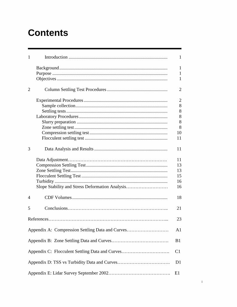
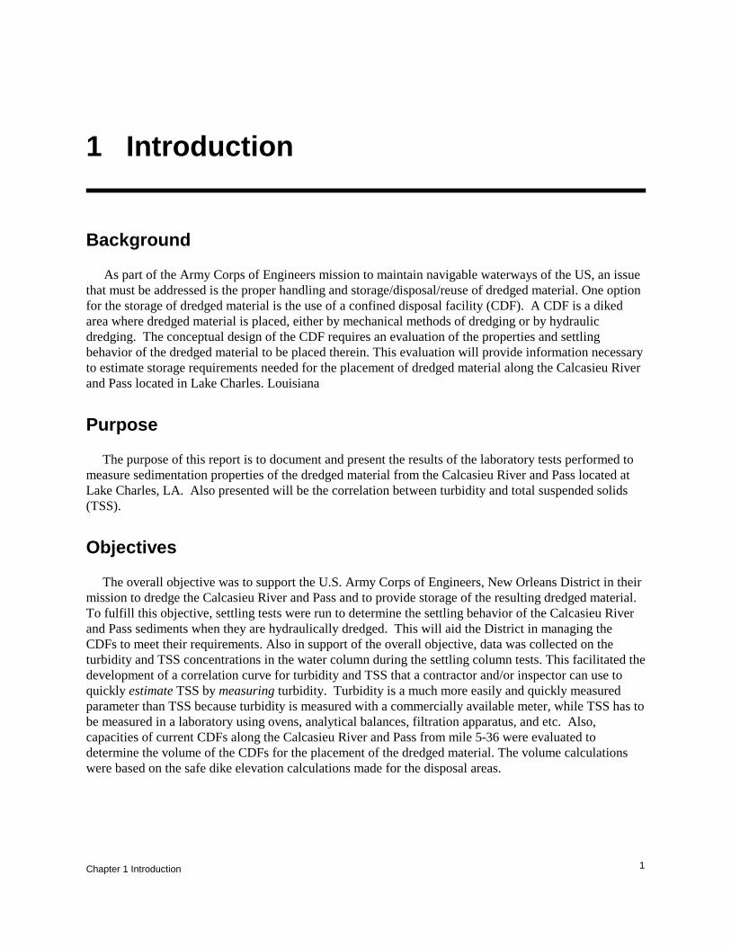
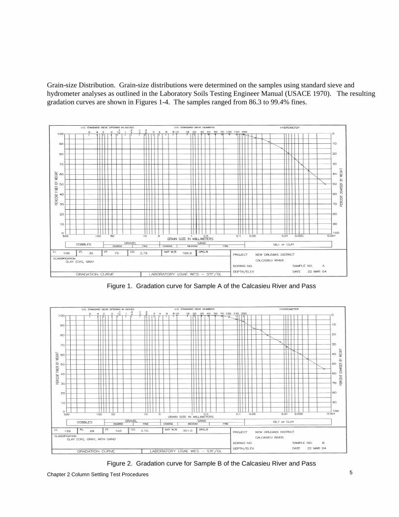
Table 1 Sediment Physical Characteristics Characteristic Sample A Sample B Sample C Sample D Specific Gravity 2.76/2.73* 2.70/2.72* 2.74/2.675* 2.74/2.69* In Situ Solids Concentration Water content 298** 169** 281** 244** Void ratio 8.2 4.6 Atterberg Limits Liquid limit 105 132 104 75 Plastic limit 30 29 29 24 Plasticity index 75 103 75 51 Grain-Size Distribution Percent gravel 0.0 0.0 0.0 0.0 Percent sand 0.6 6.3 8.3 13.7 Percent silt/clay 99.4 93.7 91.7 86.3 Classification CH CH CH CH
* Data from Eustis Engineering ** Water content was performed on samples from buckets Water Content. The in situ water content (W) of fine-grained sediment samples is also an important parameter evaluating settling behavior and the volumetric changes occurring following dredging and disposal. It should be noted that the water content in this appendix is identical to the geotechnical engineering water content. Since the water content is defined as the ratio of weight of water to weight of solids expressed as percent, it can exceed 100 percent. The procedures are given in the Laboratory Soils Testing Engineering Manual (USACE 1970). Using the specific gravity and water content, the void ratio (e) and solids concentration (S) can be expressed as follows:
100* SGWe =
eSGS
+=
1*1000
Chapter 2 Column Settling Test Procedures
5
Grain-size Distribution. Grain-size distributions were determined on the samples using standard sieve and hydrometer analyses as outlined in the Laboratory Soils Testing Engineer Manual (USACE 1970). The resulting gradation curves are shown in Figures 1-4. The samples ranged from 86.3 to 99.4% fines.
Figure 1. Gradation curve for Sample A of the Calcasieu River and Pass
Figure 2. Gradation curve for Sample B of the Calcasieu River and Pass
Chapter 2 Column Settling Test Procedures
6
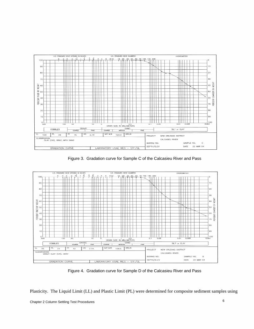
Figure 3. Gradation curve for Sample C of the Calcasieu River and Pass
Figure 4. Gradation curve for Sample D of the Calcasieu River and Pass
Plasticity. The Liquid Limit (LL) and Plastic Limit (PL) were determined for composite sediment samples using
Chapter 2 Column Settling Test Procedures
7
standard soils testing procedures as outlined in the Laboratory Soils Testing Engineer Manual (USACE 1970). The plasticity index (PI) was then computed; PI = LL – PL. Unified Soil Classification System (USCS) Classification. Visual classifications and classifications using results of the grain-size distribution and plasticity tests were determined using the USCS as outlined in the Laboratory Soils Testing Engineer Manual (USACE 1970). Settling Column Test Experimental Procedures The settling column test procedures described by Palermo, Montgomery, and Poindexter (1978), U.S. Army Corps of Engineers (USACE, 1987), and Palermo and Thackston (1988) provided the approach used to run the laboratory tests for determining the sedimentation properties of the Calcasieu River and Pass, samples A, B, C, and D, dredged material.
Settling tests The column settling tests involved mixing sediment and site water to simulate the concentration of a dredged material slurry, placing the material in a settling column, and observing the different types of settling behavior. Conducting a single settling test for the composite samples collects all three types of settling data (zone, compression, and flocculent settling data). The general procedures are described below.
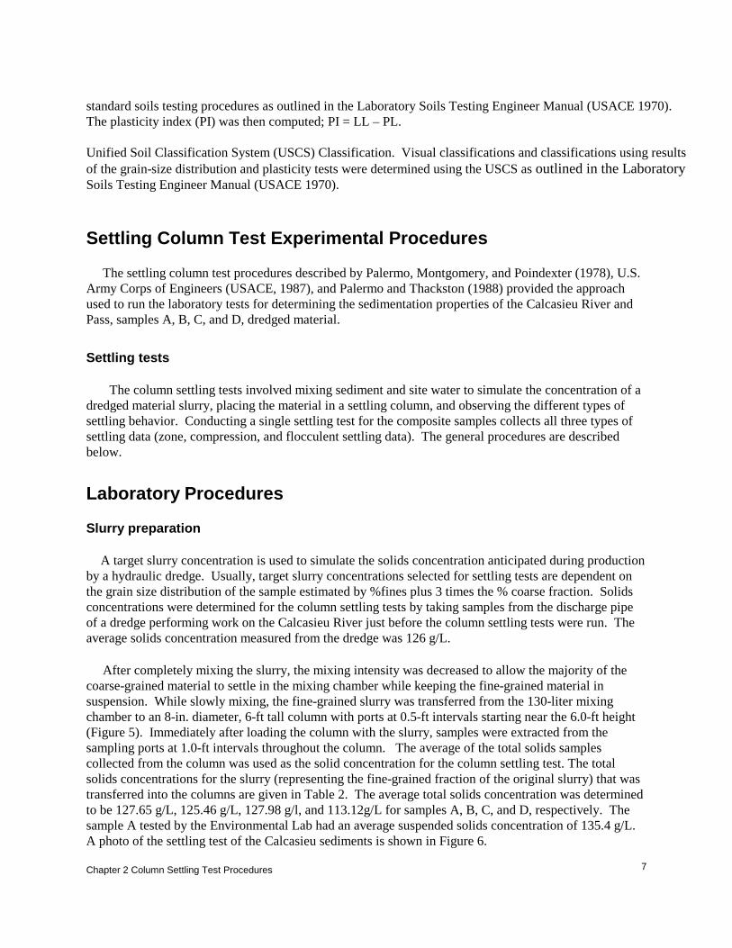
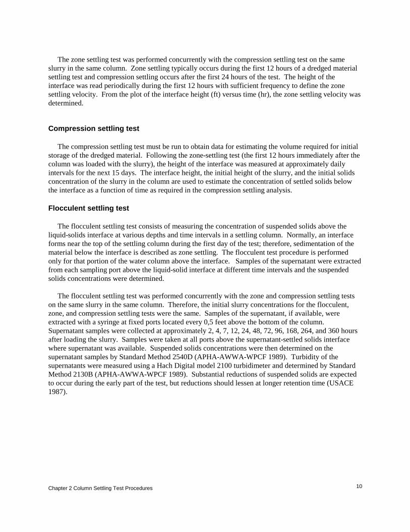
Laboratory Procedures Slurry preparation A target slurry concentration is used to simulate the solids concentration anticipated during production by a hydraulic dredge. Usually, target slurry concentrations selected for settling tests are dependent on the grain size distribution of the sample estimated by %fines plus 3 times the % coarse fraction. Solids concentrations were determined for the column settling tests by taking samples from the discharge pipe of a dredge performing work on the Calcasieu River just before the column settling tests were run. The average solids concentration measured from the dredge was 126 g/L. After completely mixing the slurry, the mixing intensity was decreased to allow the majority of the coarse-grained material to settle in the mixing chamber while keeping the fine-grained material in suspension. While slowly mixing, the fine-grained slurry was transferred from the 130-liter mixing chamber to an 8-in. diameter, 6-ft tall column with ports at 0.5-ft intervals starting near the 6.0-ft height (Figure 5). Immediately after loading the column with the slurry, samples were extracted from the sampling ports at 1.0-ft intervals throughout the column. The average of the total solids samples collected from the column was used as the solid concentration for the column settling test. The total solids concentrations for the slurry (representing the fine-grained fraction of the original slurry) that was transferred into the columns are given in Table 2. The average total solids concentration was determined to be 127.65 g/L, 125.46 g/L, 127.98 g/l, and 113.12g/L for samples A, B, C, and D, respectively. The sample A tested by the Environmental Lab had an average suspended solids concentration of 135.4 g/L. A photo of the settling test of the Calcasieu sediments is shown in Figure 6.

Chapter 2 Column Settling Test Procedures
8
Figure 5. Schematic of settling column Table 2. Total Solids Concentration of Column Slurry Sample Port Height, (ft)
Sample A (g/L)
Sample B (g/L)
Sample C (g/L)
Sample D (g/L)
1.0 127.4/131.9* 125.9 126.2 122.2
2.0 126.4/136.5* 124.5 129.3 122.5
3.0 127.2/136.6* 128.4 129.5 113.3
4.0 128.1/136.8* 123.1 130.0 112.8
5.0 129.5/136.8* 124.0 127.0 109.2
6.0 127.3/133.6* 126.9 125.9 98.7
Average 127.65/135.4* 125.46 127.98 113.12
* Denotes samples collected by Environmental Laboratory

Chapter 2 Column Settling Test Procedures
9
Figure 6. Calcasieu settling column test
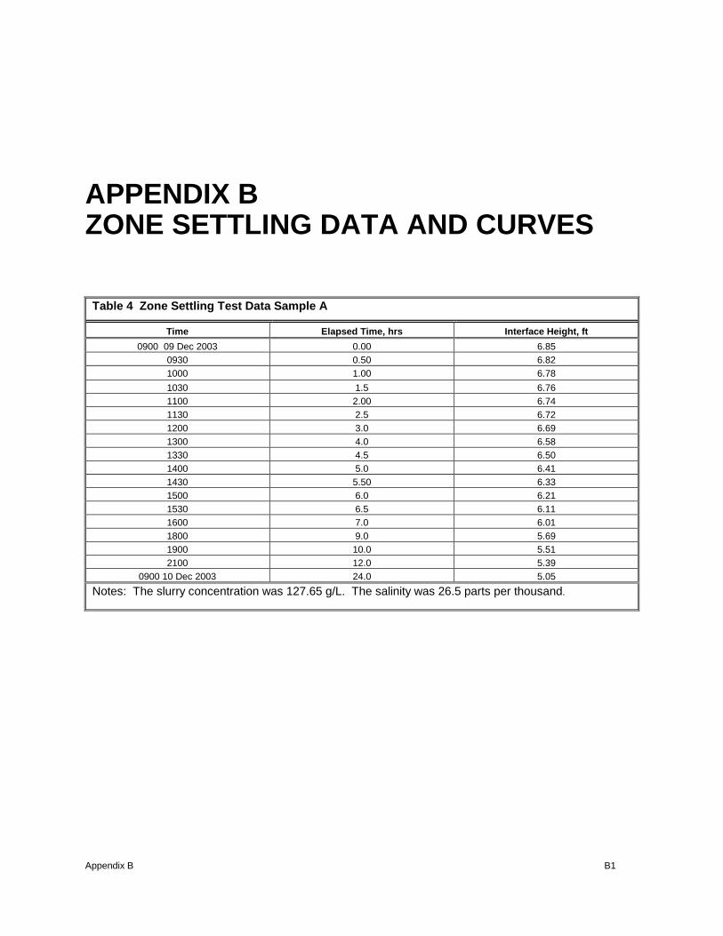
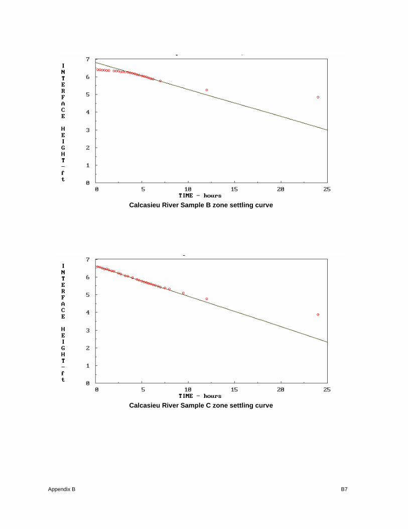
Zone settling test The zone settling test consists of recording the fall of the liquid-solids interface with time after placing the slurry in a sedimentation column. These data are plotted as height of the interface versus time. The slope of the curve in the constant velocity settling zone is the zone settling velocity, which is a function of the initial slurry concentration. The zone settling velocity is used in the design process to determine the minimum ponded area required for a given flow rate.
Chapter 2 Column Settling Test Procedures
10
The zone settling test was performed concurrently with the compression settling test on the same slurry in the same column. Zone settling typically occurs during the first 12 hours of a dredged material settling test and compression settling occurs after the first 24 hours of the test. The height of the interface was read periodically during the first 12 hours with sufficient frequency to define the zone settling velocity. From the plot of the interface height (ft) versus time (hr), the zone settling velocity was determined.
Compression settling test The compression settling test must be run to obtain data for estimating the volume required for initial storage of the dredged material. Following the zone-settling test (the first 12 hours immediately after the column was loaded with the slurry), the height of the interface was measured at approximately daily intervals for the next 15 days. The interface height, the initial height of the slurry, and the initial solids concentration of the slurry in the column are used to estimate the concentration of settled solids below the interface as a function of time as required in the compression settling analysis. Flocculent settling test The flocculent settling test consists of measuring the concentration of suspended solids above the liquid-solids interface at various depths and time intervals in a settling column. Normally, an interface forms near the top of the settling column during the first day of the test; therefore, sedimentation of the material below the interface is described as zone settling. The flocculent test procedure is performed only for that portion of the water column above the interface. Samples of the supernatant were extracted from each sampling port above the liquid-solid interface at different time intervals and the suspended solids concentrations were determined. The flocculent settling test was performed concurrently with the zone and compression settling tests on the same slurry in the same column. Therefore, the initial slurry concentrations for the flocculent, zone, and compression settling tests were the same. Samples of the supernatant, if available, were extracted with a syringe at fixed ports located every 0,5 feet above the bottom of the column. Supernatant samples were collected at approximately 2, 4, 7, 12, 24, 48, 72, 96, 168, 264, and 360 hours after loading the slurry. Samples were taken at all ports above the supernatant-settled solids interface where supernatant was available. Suspended solids concentrations were then determined on the supernatant samples by Standard Method 2540D (APHA-AWWA-WPCF 1989). Turbidity of the supernatants were measured using a Hach Digital model 2100 turbidimeter and determined by Standard Method 2130B (APHA-AWWA-WPCF 1989). Substantial reductions of suspended solids are expected to occur during the early part of the test, but reductions should lessen at longer retention time (USACE 1987).

Chapter 3 Data Analysis and Results for Column Settling Test
11
3 Data Analysis and Results for Column Settling Test The behavior of the Calcasieu sediment at slurry concentrations equal to that expected for inflow to a CDF is governed by zone settling processes. The sediments exhibited a clear interface between settled material and clarified supernatant. The settling test data were analyzed using the Automated Dredging and Disposal Alternative Management Systems (ADDAMS) (Schroeder and Palermo 1995) which is a family of computer programs developed at ERDC to assist in planning designing, and operating dredging and dredged material disposal projects. The SETTLE module of ADDAMS was used for the settling test data (Hayes and Schroeder 1992). Data adjustment Column settling tests were performed by Eustis on four sediment samples (A, B, C, D) from the Calcasieu River. A replicate of Sample A was also tested at ERDC. Upon examination of the Eustis data, it was discovered that the column settling tests were not performed exactly according to the column testing procedure guidance. At each sample interval, samples were taken from both above and below the sediment-water interface for Total Suspended Solids (TSS) and Total Solids (TS) analyses, respectively. The procedure guidance calls for only sampling below the interface for TS at the beginning of the test, and from that point on, sampling only above the interface for TSS. Sampling below the interface throughout the test caused the measurements of the interface height over time to be lower than they should have been. Other effects could also have occurred, such as disturbance of the column, which may affect the settling rate, although there is no way to know these effects. The interface height measurements by Eustis include height reduction due to settling of the solids and sampling. To develop settling curves, the interface height as a function only of compression settling is needed. To account for the effect on the interface height, a series of calculations were performed to estimate what the interface height should have been in the absence of sampling. The calculations used to correct the interface height are based on the mass lost during each sampling event. In theory, if sampling below the interface does not occur, the mass (M) of solids in the column remains constant. The mass (M) is equal to the solids concentration (C) times volume (V) below the solids interface, or since the column area is constant, we can simplify using the interface height (H) rather than volume; so M = CH. The following definitions will be used to develop the equations for estimating the theoretical interface height without sampling.

Chapter 3 Data Analysis and Results for Column Settling Test
12
Mo -original mass Mi -actual mass (after sampling) at time i Co -original solids concentration (average TS from initial TS sampling) C i -average solids concentration at time i, (average TS from TS sampling at time i) Ci -solids concentration at time i (calculated based on mass at time i) Ho -original height (slurry height at start of test, after initial TS sampling) Hi -actual height at time i, (recorded interface height) ΔHi -height differential at time i due to sampling Hoi’ -theoretical original height if had started with mass Mi Hi’ -theoretical height at time I if had not sampled Mo’ -original mass if had started with the actual mass at time i, = Mi Mi’ -theoretical mass at time i, = Mo The original mass of solids in the column can be calculated as
ooo CHM = Without sampling, mass is constant, Mo = Mi. However, since sampling occurred, a portion of the solids mass was removed at each sampling event, and Mo ≠ Mi. Mi can be calculated as the original mass minus the cumulative mass lost:
∑∆−=n
iiiooi CHCHM
Then, the theoretical original height, if had started with mass Mi, can be calculated as:
o
ioi C
MH ='
Then, mass at time i is equal to the theoretical original mass (Mi = Mo’), which is equal to the original solids concentration times theoretical original height:
''oooiiii MCHCHM ===
Or, solving for the concentration at time i,
i
ooii H
CHC
'
=
Then, the theoretical mass (had sampling not occurred) at time i, Mi’ should equal the concentration at
Chapter 3 Data Analysis and Results for Column Settling Test
13
time i times the theoretical height at time i, and should equal the original mass (Mo = Mi’):
''iiiooo MCHCHM ===
Rearranging, to solve for the theoretical height at time i:
i
ooi C
CHH ='
This series of equations was used to adjust the data from Eustis to estimate the interface height had sampling below the interface not occurred. The computed values of Hi’ from each column settling test were used to develop the compression settling curves.
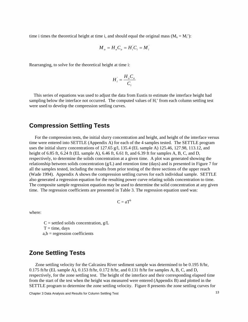
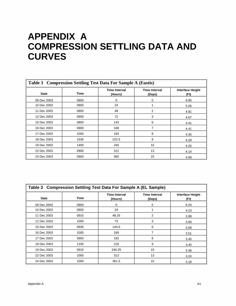
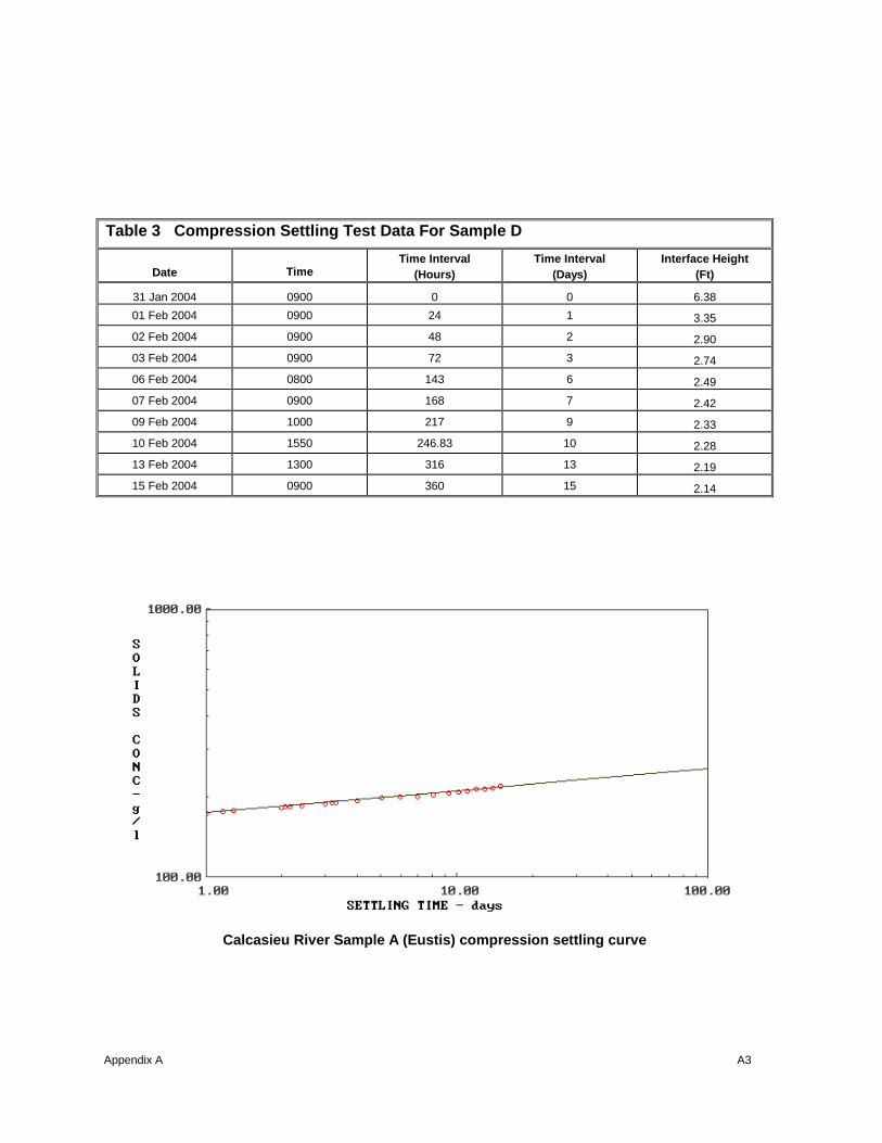
Compression Settling Tests For the compression tests, the initial slurry concentration and height, and height of the interface versus time were entered into SETTLE (Appendix A) for each of the 4 samples tested. The SETTLE program uses the initial slurry concentrations of 127.65 g/l, 135.4 (EL sample A) 125.46, 127.98, 113.12, and height of 6.85 ft, 6.24 ft (EL sample A), 6.46 ft, 6.61 ft, and 6.39 ft for samples A, B, C, and D, respectively, to determine the solids concentration at a given time. A plot was generated showing the relationship between solids concentration (g/L) and retention time (days) and is presented in Figure 7 for all the samples tested, including the results from prior testing of the three sections of the upper reach (Wade 1994). Appendix A shows the compression settling curves for each individual sample. SETTLE also generated a regression equation for the resulting power curve relating solids concentration to time. The composite sample regression equation may be used to determine the solid concentration at any given time. The regression coefficients are presented in Table 3. The regression equation used was:
C = aTb where: C = settled solids concentration, g/L T = time, days a,b = regression coefficients
Zone Settling Tests Zone settling velocity for the Calcasieu River sediment sample was determined to be 0.195 ft/hr, 0.175 ft/hr (EL sample A), 0.153 ft/hr, 0.172 ft/hr, and 0.131 ft/hr for samples A, B, C, and D, respectively, for the zone settling test. The height of the interface and their corresponding elapsed time from the start of the test when the height was measured were entered (Appendix B) and plotted in the SETTLE program to determine the zone settling velocity. Figure 8 presents the zone settling curves for

Chapter 3 Data Analysis and Results for Column Settling Test
14
all samples tested. Appendix B presents the zone settling curves for each individual sample. When the zone settling curve departs from a linear relationship, compression settling begins. The transition from zone to compression settling occurred between 10 and 12 hours (Appendix B). The zone settling velocity is adjacent to the plot of the zone settling data.
Table 3. Compression Settling Regression Coefficients Coefficient Sample A Sample A (EL) Sample B Sample C Sample D
a 174 198 179 221 231
b 0.083 0.105 0.092 0.118 0.186
Calcasieu - Compression Settling Test Curves
100.00
1000.00
1 10 100
Time, days
Solid
s C
once
ntra
tion,
g/L Upper Reach 1
Upper Reach 2Upper Reach 3Sample A (ERDC)Sample A1Sample B1Sample C1Sample D1
Figure 7. Compression settling curves for all samples.

Chapter 3 Data Analysis and Results for Column Settling Test
15
Calcasieu - Zone Settling Curves
0
1
2
34
5
6
7
0 2 4 6 8 10 12
Time, hr
Inte
rfac
e D
epth
, ft (
star
ting
at 6
ft)
Upper Reach 1Upper Reach 2Upper Reach 3Sample A (ERDC)Sample A1Sample B1Sample C1Sample D1
Figure 8. Zone settling curves for all samples, assuming initial slurry height of 6.0 feet
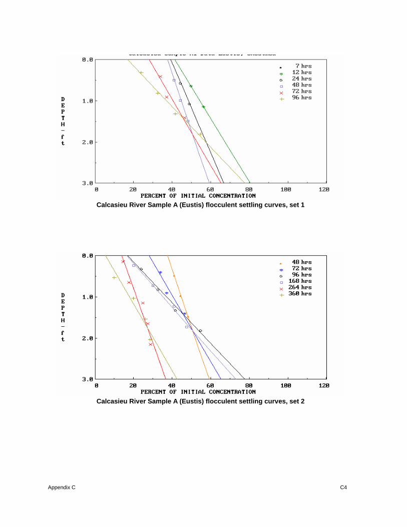
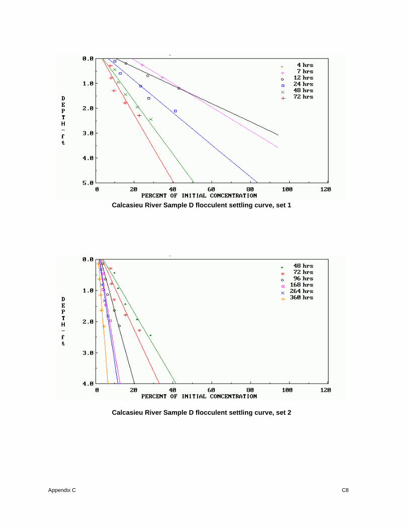
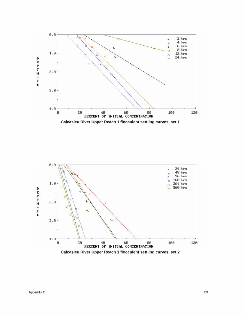
Flocculent Settling Tests An extension of the flocculent settling test is presented in USACE (1987). Palermo (1985) analyzed the effects of several possible assumptions regarding the magnitude of the value to be used as the initial concentration in the laboratory test and showed that all gave essentially the same final result. Therefore, it was recommended that, for simplicity, the concentration in the first sample taken at the highest sampling port be used as the initial concentration. SETTLE generates two curves based on the settle data presented in Appendix C. The plot generated by SETTLE is the concentration profile curve (Appendix C). The concentration profile curve, which plots the depth below the surface (ft) versus percent of initial concentration, shows that the suspended solids concentrations decrease with time and increase at deeper ponding depths (1, 2, and 3 ft) at the weir. The actual depth of withdrawal is a function of the flow rate and the weir length; the depth is shallower for lower flow rates and longer weir lengths. The supernatant suspended solids curves derived from the concentration profile curves compare the effects of retention time on the supernatant suspended solids concentration at 1-, 2-, and 3-ft ponding depths. Figure 9 shows that increasing the retention time beyond 24 hr for 1, 2, or 3 ft of ponding depth provide little additional improvement in supernatant suspended solids concentration. Actual field suspended solids will be somewhat greater because of resuspension by wind and wave action. Based on field experience, a re-suspension factor is estimated to range from 1.5 to 2.5 depending on ponding depth and surface area (Shields, Schroeder, and Thackson 1987) (Table 4).
Chapter 3 Data Analysis and Results for Column Settling Test
16
Table 4 Recommended Re-suspension Factors For Various Ponding Areas and Depths Anticipated Average Ponded Depth Anticipated Ponded Area Less than 2 ft 2 ft or Greater Less than 100 acres 2.0 1.5 Greater than 100 acres 2.5 2.0
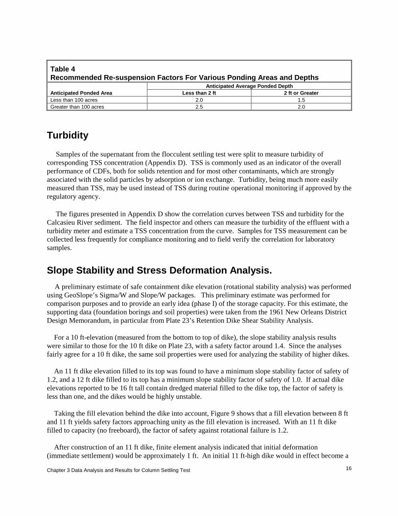
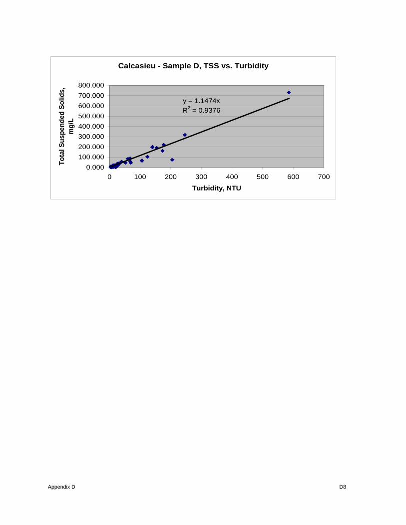
Turbidity Samples of the supernatant from the flocculent settling test were split to measure turbidity of corresponding TSS concentration (Appendix D). TSS is commonly used as an indicator of the overall performance of CDFs, both for solids retention and for most other contaminants, which are strongly associated with the solid particles by adsorption or ion exchange. Turbidity, being much more easily measured than TSS, may be used instead of TSS during routine operational monitoring if approved by the regulatory agency. The figures presented in Appendix D show the correlation curves between TSS and turbidity for the Calcasieu River sediment. The field inspector and others can measure the turbidity of the effluent with a turbidity meter and estimate a TSS concentration from the curve. Samples for TSS measurement can be collected less frequently for compliance monitoring and to field verify the correlation for laboratory samples. Slope Stability and Stress Deformation Analysis. A preliminary estimate of safe containment dike elevation (rotational stability analysis) was performed using GeoSlope’s Sigma/W and Slope/W packages. This preliminary estimate was performed for comparison purposes and to provide an early idea (phase I) of the storage capacity. For this estimate, the supporting data (foundation borings and soil properties) were taken from the 1961 New Orleans District Design Memorandum, in particular from Plate 23’s Retention Dike Shear Stability Analysis. For a 10 ft-elevation (measured from the bottom to top of dike), the slope stability analysis results were similar to those for the 10 ft dike on Plate 23, with a safety factor around 1.4. Since the analyses fairly agree for a 10 ft dike, the same soil properties were used for analyzing the stability of higher dikes. An 11 ft dike elevation filled to its top was found to have a minimum slope stability factor of safety of 1.2, and a 12 ft dike filled to its top has a minimum slope stability factor of safety of 1.0. If actual dike elevations reported to be 16 ft tall contain dredged material filled to the dike top, the factor of safety is less than one, and the dikes would be highly unstable. Taking the fill elevation behind the dike into account, Figure 9 shows that a fill elevation between 8 ft and 11 ft yields safety factors approaching unity as the fill elevation is increased. With an 11 ft dike filled to capacity (no freeboard), the factor of safety against rotational failure is 1.2. After construction of an 11 ft dike, finite element analysis indicated that initial deformation (immediate settlement) would be approximately 1 ft. An initial 11 ft-high dike would in effect become a

Chapter 3 Data Analysis and Results for Column Settling Test
17
10 ft-high dike. Based on the preliminary analyses for slope stability and initial stress deformation, it is recommended that the retention dikes be built no higher than 11 ft in elevation, with freeboard for 10 ft dredged material fill elevation. The factor of safety against slope failure should be between 1.2 and 1.3.
1.4 1.4 1.2 1.1 1 0.8 0.7123456789
10111213141516
DikeheightFillheightSafetyFactor
Figure 9. Fill elevation Versus safety factor for dike elevations
Alternatives for allowing higher dike elevations such as soil modification or reinforcement were not explored in this report. Higher dike elevations should be possible using such techniques, based on past projects in Mobile District, Norfolk District, and others.
Chapter 4 CDF Volumes
18
4 CDF Volumes ___________________________________ Based on the data from the column settling tests, the CDF capacities were calculated for varying fill elevations and volumes. A lidar survey of the disposal areas was provided by the New Orleans District that provided data on the dike elevation of each CDF and the volume at varying fill elevations. The CDFs were grouped into three groups that represent the three reaches of the Calcasieu River that were studied for this phase of the DMMP. The upper reach incorporated CDFs 1 through 12B, the middle reach consisted of CDFs 13 through E, and the lower reach consisted of CDFs H, M, and N. Appendix E presents the lidar survey that was used for calculating the fill elevations.
The data for the column settling test for the upper reach, mile 24 to 36, was obtained from the study performed by Wade in 1994. The upper reach for the Wade report was divided in to three sub-reaches due to differences in the geotechnical characteristics of the sediments found in the upper reach. The three sub-reaches were identified as Reach 1, mile 33-36, Reach 2, mile 30-33, and Reach 3, Mile 24-30. The in-situ volume of material to be dredged from Reaches 1, 2, and 3 are 1.52 million yd3, 1.73 million yd3, and 3.25 million yd3, respectively, for a total of 6.5 million cubic yards. Based on these volumes the SETTLE model computes the storage area needed for the material but does not include ponding within the CDF or freeboard. SETTLE models were run using two different dredge sizes, 27 inch and 30 inch. Using the settling column data, geotechnical data, and dredge size, Reach 1 requires a storage capacity of 2,180,950 yd3 for the 27 inch dredge and 2,250,217 yd3 for the 30 inch dredge. Reach 2 requires 1,519,669 yd3 for the 27 inch dredge and 1,563,445 yd3 dredge. Reach 3 requires 3,744,171 yd3 for the 27 inch dredge and 3,852,476 yd3 for the 30 inch dredge. The total volume requirement for the upper reach of the Calcasieu River is 7,444,790 yd3 for a 27 inch dredge and 7,666,138 yd3 for a 30 inch dredge.
Based on the Lidar surveys of disposal areas 1-12B, volumes were calculated at three different fill elevations. These elevations were 10 feet, 12 feet, and 14 feet. This was assuming a 2- foot freeboard within the disposal area so the dikes would be 2 feet higher than the fill elevations. Ponded area was not considered for this evaluation but should be added to assure adequate effluent quality and settling of the material within the CDF. At the 10- foot fill elevation, the volume of the present CDFs is 3,751,821 yd3. The 12-foot fill elevation had a volume of 4,412,484 yd3 and the 14-foot fill elevation had a volume of 4,537,518 yd3. With the information provided on the safe dike elevation of 11 feet, with a safety factor of 1.2, it is not recommended going above this elevation for the dikes unless measures are taken to reinforce the dikes to prevent failure. The 10-foot fill elevation calculations were performed assuming a 12- foot elevation dike with a safety factor of 1.0.
The middle reach of the river, mile 14-24, has 4,500,000 yd3 of in-situ material to be removed from the channel. The storage area needed for this material using a 27 inch and 30 inch dredge varies from between 4.5 and 9.6 million cubic yards. The large variance of volume needed for the material is due to the fact that the samples collected for the column settling tests had a wide range of moisture content. The moisture content of samples A, B, C, and D ranged from approximately 170% to almost 300%. Since

Chapter 4 CDF Volumes
19
these were grab samples and not cores taken from the channel these results could be misleading and not reflect what is actually present in the channel. Due to this, a range of moisture contents were input into the SETTLE model to predict the volume needed for storage of the dredged material. Using the 10- foot, 12- foot, and 14- foot fill elevations for the disposal areas used for the middle reach, the volumes that are currently available are 1,277,765 yd3, 1,810,167 yd3, and 2,520,037 yd3, respectively.
The lower reach of the river, mile 5-14, has approximately 4 million cubic yards of in-situ material to be dredged from the river. Using calculations for a 27 and 30 inch dredge, the storage capacity needed for the lower reach CDFs ranges between 4 and 9 million cubic yards. Like the middle reach, the samples collected varied in moisture content so different moisture contents were entered into SETTLE in order to obtain a range of the storage volume needed to hold the 4 million cubic yards of in-situ material. The CDFs on the lower reach of the river do not presently have dike elevations over 10 feet. Site H has a dike elevation of 10 feet, site M has an elevation of 6 feet, and site N has a dike elevation of 8 feet in the front and 6 feet in the back. Due to these dike elevations there is only a capacity of 567,896 yd3 for the placement of dredged material in the lower reach. Depending on the scheduling of the dredging to be performed on the Calcasieu River, disposal areas E and D could be used for some of the dredging done for the lower reach. Table 5 shows that depending on the dike elevation, this would increase the lower reach storage capacity to approximately 1 million cubic yards based on the 10 foot dike elevation. It should be noted that if these areas are used for the lower reach then the capacity for the middle reach will be decreased for the storage of the dredged material from that reach.
The total amount of sediment to be dredged for the Calcasieu River between miles 5 and 36 is 15 million cubic yards of in-situ material. Depending on the dredge size used, 27 or 30 inches, the total storage area needed to dispose of this material is between 16 and 26.5 million cubic yards. The range of the storage area needed is due to the fact that water contents used for the model runs were 100%, 150%, 200%, 250%, and 300% due to the fact that the samples collected and those previously done by Wade in 1994 varied from around 100% to close to 300%. Table 5 presents the current capacities for each CDF used for the placement of dredged material from miles 5-36 along the Calcasieu River. Table 8 presents the storage capacity for each CDF at the 10 foot, 12 foot, and 14 foot fill elevation along with the total volume of material to be dredged.

Chapter 4 CDF Volumes
20
Table 5. Storage capacity of current CDFs using varying fill elevations
Disposal Area
Current capacity fill up to
10’
Current capacity fill up to
10’
Current capacity fill
up to 12’
Current capacity fill up to
12’
Current capacity fill up to
14’
Current capacity fill
up to 14’
In Situ dredge volume
Capacity needed for
30” dredge
1 150,041 292,014 292,014
2 48,400 153,267 278,301
3 (Clooney Island)
194,407 509,815 509,815
4 171,014 171,014 171,014
5 192,794 291,208 291,208
6 Out Out Out
7 772,790 772,790 772,790
8 909,924 909,924 909,924
9 0 0 0
10 204,894 204,894 204,894
11 197,634 197,634 197,634
12A 258,134 258,134 258,134
12B 651,789 3,751,821 651,789 4,412,484 651,789 4,537,518 6,500,000 7,666,138
13 (Choupique Island)
379,135 379,135 379,135
15 422,695 422,695 422,695
16N 0 0 0
16S Out Out Out
17 0 0 0
22 0 145,201 145,201
23 0 24,200 161,334
D 121,000 484,002 1,056,737
E 354,935 1,277,765 354,935 1,810,167 354,935 2,520,037 4,500,000 4.5 to 9.8 MCY
H 164,561 164,561 164,561
M 403,335 403,335 403,335
N 0 567,896 0 567,896 0 567,896 4,000,000 4.0 to 9.0 MCY
Total 5,597,482 5,597,482 6,790,547 6,790,547 7,625,450 7,625,450 15,000,000 16.2 to 26.5 MCY

Chapter 5 Conclusions
21
5 Conclusions Conclusions Based on the result of the settling tests, consolidation tests, and turbidity measurements, it is concluded that: a. Dredged material from the Calcasieu River and Pass is predominantly fine grain material in the middle and lower reaches accounting for approximately 90 % of the material. The upper reach of the study area averages approximately 40 % sand and 60 % fines. b. The Calcasieu River sediment exhibited zone settling. The zone settling velocity was 0.195 ft/hr, 0.175 ft/hr (EL sample A), 0.153 ft/hr, 0.172 ft/hr, and 0.131 ft/hr for samples A, B, C, and D, respectively. c. The curves developed for the correlation between TSS and turbidity for the 4 samples had varying R2 values ranging from0.4611 to 0.9636. It is suggested that the curve developed by ERDC be used for determining the correlation between TSS and turbidity. It should be noted that this is a rough approximation and should be used for no other reason than to estimate TSS. d. A slope stability analysis was performed to approximate the safe dike elevation that could be used for the disposal areas. The analysis was performed using data supplied by the New Orleans District in a 1961 memorandum. The safe dike elevation was determined to be 11 feet with a safety factor of 1.2. A dike elevation of 12 feet gives a safety factor of 1.0. It is recommended that dikes not be built above the 11 foot elevation unless measures are taken to strengthen the foundation materials so as to reduce the chance of dike failure. e. Water contents varied greatly for the samples collected from sites A, B, C, and D. Due to this, and the fact that the upper reach samples previously collected by Wade, 1994 were lower, a range of water contents were used in running the SETTLE model. This resulted in a range of estimated dredged material storage requirements in the middle and lower reaches. More accurate estimates could be achieved if representative water contents were available for the in-situ material to be dredged in each reach. f. The total volume of material to be dredged from the Calcasieu River and Pass in the short term is 15,000,000 yd3. The upper reach has a total of 6.5MCY, the middle reach has a total of 4.5 MCY, and the lower reach has a total of 4.0 MCY.

Chapter 5 Conclusions
22
g. Depending on the size dredge used for the removal of the material, 27 or 30 inch, the upper reach requires a storage volume of 7.5 to 7.75 MCY. The middle reach requires a storage area between 4.5 and 9.8 MCY. The lower reach requires a storage volume of between 4.0 and 9.0 MCY. The total area needed for storage between miles 5 and 36 is between 16.0 and 26.5 MCY. h. Three fill elevations were used to determine the present storage capacities of the CDFs along the Calcasieu River. The 10-foot fill elevation has a storage capacity of approximately 5.6 MCY, the 12-foot fill elevation has a storage capacity of approximately 6.8 MCY, and the 14-foot fill elevation has a storage capacity of approximately 7.6 MCY i. From the results of the column settling tests and the SETTLE model for the samples collected and the data from Wade 1994, the results indicate that the storage volume present in the CDFs along the Calcasieu River and Pass is not adequate for the storage of all the dredged material that is proposed to be removed in the next 1-3 years. j. A long-term DMMP needs to performed on the Calcasieu River and Pass to address the issue of the lack of storage capacity for the placement of dredged material over the next 20 years. This DMMP would look at management of the existing CDFs and the siting of new disposal areas along with other uses of the dredged material such as beneficial uses and erosion control.

References 23
References APHA-AWWA-WPCF. (1989). Standard methods - for the examination of water and wastewater. 17th Edition, Washington, DC. Cargill, K.W. (1983). "Procedures for prediction of consolidation in soft fine-grained dredged material," Technical Report D-83-1, U.S. Army Engineer Waterways Experiment Station, Vicksburg, MS. Corp of Engineers, Department of the Army. (1987). Confined disposal of dredged material. Engineer Manual 1110-2-5027, Washington, DC. Hayes, D.F. and Schroeder, P.R. (1992). "Documentation of the SETTLE Module for ADDAMS: Design of Confined Disposal Facilities for Solids Retention and Initial Storage," Environmental Effects of Dredging Technical Notes EEDP-06-18, U.S. Army Engineer Waterways Experiment Station, Vicksburg, MS. Palermo, M.R., Montgomery, R.L., and Poindexter, M.E. (1978). Guidelines for designing, operating, and managing dredged material containment areas, Technical Report DS-78-10, U.S. Army Engineer Waterways Experiment Station, Vicksburg, MS. Palermo, M.R. and Thackston, E.L. (1988). Refinement of column settling test procedures for estimating the quality of effluent from confined dredged material disposal areas, Technical Report D-88-9, U.S. Army Engineer Waterways Experiment Station, Vicksburg, MS. Schroeder, P.R. and Palermo, M.R. (1995). The Automated Dredging and Disposal Alternatives Management System (ADDAMS), Environmental Effects of Dredging Programs Technical Note EEDP-06-12, U.S. Army Engineer Waterways Experiment Station, Vicksburg, MS. Shields, D.F., Schroeder, P.R., and Thackston, E.L. (1987). Design and management of dredged material containment areas to improve hydraulic performance, Technical Report D-87-2, U.S. Army Engineer Waterways Experiment Station, Vicksburg, MS. Wade, R. (1994). “Calcasieu River sediment removal study,” Technical Report EL-94-9, U.S. Army Engineer Waterways Experiment Station, Vicksburg, MS.
Appendix A A1
APPENDIX A COMPRESSION SETTLING DATA AND CURVES
Table 3 Compression Settling Test Data For Sample A (Eustis)
Date Time Time Interval
(Hours) Time Interval
(Days) Interface Height
(Ft)
09 Dec 2003 0900 0 0 6.85 10 Dec 2003 0900 24 1 5.05 11 Dec 2003 0900 48 2 4.81 12 Dec 2003 0900 72 3 4.67 15 Dec 2003 0800 143 6 4.41 16 Dec 2003 0900 168 7 4.41 17 Dec 2003 1000 193 8 4.35 18 Dec 2003 1530 222.5 9 4.29 19 Dec 2003 1400 245 10 4.25 22 Dec 2003 0900 312 13 4.14 24 Dec 2003 0900 360 15 4.08
Table 3 Compression Settling Test Data For Sample A (EL Sample)
Date Time Time Interval
(Hours) Time Interval
(Days) Interface Height
(Ft)
09 Dec 2003 0900 0 0 6.24 10 Dec 2003 0900 24 1 4.23 11 Dec 2003 0915 48.25 2 3.98 12 Dec 2003 1000 73 3 3.83 15 Dec 2003 0930 144.5 6 3.58 16 Dec 2003 1000 169 7 3.51 17 Dec 2003 0900 192 8 3.45 18 Dec 2003 1100 218 9 3.40 19 Dec 2003 0915 240.25 10 3.36 22 Dec 2003 1000 313 13 3.24 24 Dec 2003 1000 361.5 15 3.18

Appendix A A2
Table 3 Compression Settling Test Data For Sample B
Date Time Time Interval
(Hours) Time Interval
(Days) Interface Height
(Ft)
30 Dec 2003 0830 0 0 6.46 31 Dec 2003 0830 24 1 4.88 01 Jan 2004 0830 48 2 4.63 02 Jan 2004 0830 72 3 4.52 05 Jan 2004 0830 144 6 4.26 06 Jan 2004 0830 168 7 4.21 7 Jan 2004 1020 193.83 8 4.16 8 Jan 2004 0830 216 9 4.12 9 Jan 2004 1045 242.25 10 4.09 12 Jan 2004 1300 316.5 13 3.98 14 Jan 2004 0830 360 15 3.93
Table 3 Compression Settling Test Data For Sample C
Date Time Time Interval
(Hours) Time Interval
(Days) Interface Height
(Ft)
15 Jan 2004 0800 0 0 6.61 16 Jan 2004 0800 24 1 3.92 17 Jan 2004 0800 48 2 3.65 18 Jan 2004 0800 72 3 3.52 21 Jan 2004 1530 151 6 3.28 22 Jan 2004 0800 168 7 3.24 23 Jan 2004 1600 200 8 3.20 24 Jan 2004 1230 220.5 9 3.14 25 Jan 2004 1200 244 10 3.10 28 Jan 2004 0800 312 13 3.01 30 Jan 2004 0800 360 15 2.98
Appendix A A3
Table 3 Compression Settling Test Data For Sample D
Date Time Time Interval
(Hours) Time Interval
(Days) Interface Height
(Ft)
31 Jan 2004 0900 0 0 6.38 01 Feb 2004 0900 24 1 3.35 02 Feb 2004 0900 48 2 2.90 03 Feb 2004 0900 72 3 2.74 06 Feb 2004 0800 143 6 2.49 07 Feb 2004 0900 168 7 2.42 09 Feb 2004 1000 217 9 2.33 10 Feb 2004 1550 246.83 10 2.28 13 Feb 2004 1300 316 13 2.19 15 Feb 2004 0900 360 15 2.14
Calcasieu River Sample A (Eustis) compression settling curve

Appendix A A4
Calcasieu River Sample A (ERDC) compression settling curve
Calcasieu River Sample B compression settling curve

Appendix A A5
Calcasieu River Sample C compression settling curve
Calcasieu River Sample D compression settling curve

Appendix A A6
Calcasieu River Upper Reach 1 compression settling curve
Calcasieu River Upper Reach 2 compression settling curve

Appendix A A7
Calcasieu River Upper Reach 3 compression settling curve
Appendix B B1
APPENDIX B ZONE SETTLING DATA AND CURVES
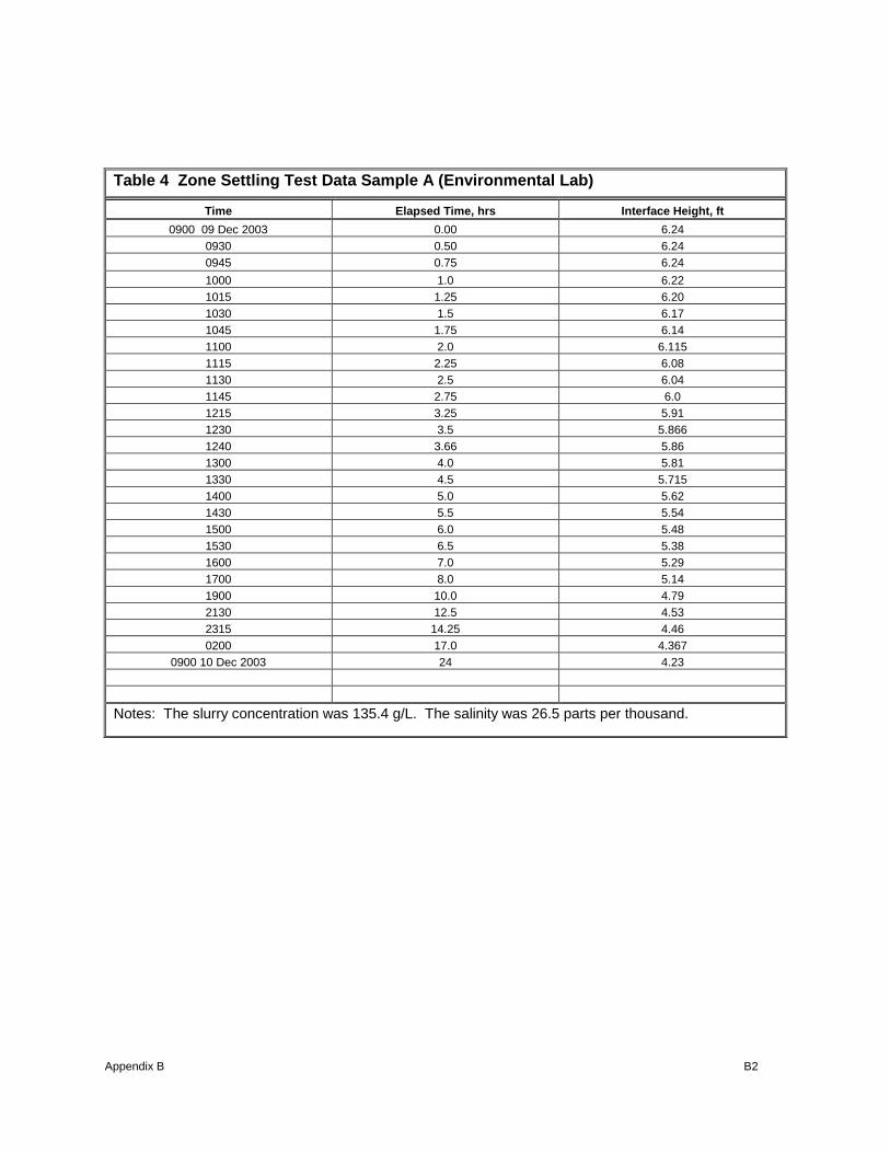
Table 4 Zone Settling Test Data Sample A
Time Elapsed Time, hrs Interface Height, ft 0900 09 Dec 2003 0.00 6.85
0930 0.50 6.82 1000 1.00 6.78 1030 1.5 6.76 1100 2.00 6.74 1130 2.5 6.72 1200 3.0 6.69 1300 4.0 6.58 1330 4.5 6.50 1400 5.0 6.41 1430 5.50 6.33 1500 6.0 6.21 1530 6.5 6.11 1600 7.0 6.01 1800 9.0 5.69 1900 10.0 5.51 2100 12.0 5.39
0900 10 Dec 2003 24.0 5.05 Notes: The slurry concentration was 127.65 g/L. The salinity was 26.5 parts per thousand.
Appendix B B2
Table 4 Zone Settling Test Data Sample A (Environmental Lab)
Time Elapsed Time, hrs Interface Height, ft 0900 09 Dec 2003 0.00 6.24
0930 0.50 6.24 0945 0.75 6.24 1000 1.0 6.22 1015 1.25 6.20 1030 1.5 6.17 1045 1.75 6.14 1100 2.0 6.115 1115 2.25 6.08 1130 2.5 6.04 1145 2.75 6.0 1215 3.25 5.91 1230 3.5 5.866 1240 3.66 5.86 1300 4.0 5.81 1330 4.5 5.715 1400 5.0 5.62 1430 5.5 5.54 1500 6.0 5.48 1530 6.5 5.38 1600 7.0 5.29 1700 8.0 5.14 1900 10.0 4.79 2130 12.5 4.53 2315 14.25 4.46 0200 17.0 4.367
0900 10 Dec 2003 24 4.23
Notes: The slurry concentration was 135.4 g/L. The salinity was 26.5 parts per thousand.

Appendix B B3
Table 4 Zone Settling Test Data Sample B
Time Elapsed Time, hrs Interface Height, ft 0830 30 Dec 2003 0.00 6.46
0845 0.25 6.44 0900 0.50 6.42 0915 0.75 6.40 0930 1.0 6.40 0945 1.25 6.38 1000 1.50 6.37 1030 2.0 6.36 1045 2.25 6.36 1100 2.5 6.35 1115 2.75 6.31 1130 3.0 6.31 1145 3.25 6.30 1200 3.50 6.28 1215 3.75 6.25 1230 4.0 6.22 1245 4.25 6.20 1300 4.50 6.16 1315 4.75 6.12 1330 5.0 6.08 1345 5.25 6.05 1400 5.50 6.01 1415 5.75 5.97 1430 6.0 5.93 1445 6.25 5.89 1530 7.0 5.78 2030 12.0 5.28
0830 31 Dec 2004 24 4.88 Notes: The slurry concentration was 125.46 g/L. The salinity was 26.5 parts per thousand.

Appendix B B4
Table 4 Zone Settling Test Data Sample C
Time Elapsed Time, hrs Interface Height, ft 0800 15 Jan 2004 0.00 6.61
0815 0.25 6.60 0830 0.5 6.57 0845 0.75 6.54 0900 1.0 6.49 0915 1.25 6.47 0930 1.50 6.43 0945 1.75 6.37 1000 2.0 6.34 1030 2.5 6.26 1045 2.75 6.21 1115 3.25 6.10 1130 3.50 6.08 1200 4.0 6.00 1230 4.5 5.90 1245 4.75 5.83 1300 5.0 5.79 1315 5.25 5.74 1330 5.50 5.71 1345 5.75 5.66 1400 6.0 5.63 1415 6.25 5.58 1430 6.50 5.55 1445 6.75 5.50 1500 7.0 5.47 1530 7.50 5.42 1600 8.0 5.35 1730 9.5 5.13 2000 12.0 4.79
0800 16 Jan 2004 24 3.92 Notes: The slurry concentration was 127.65 g/L. The salinity was 26.5 parts per thousand.

Appendix B B5
Table 4 Zone Settling Test Data Sample D
Time Elapsed Time, hrs Interface Height, ft 0900 31 Jan 2004 0.00 6.38
0915 0.25 6.36 0930 0.50 6.32 0945 0.75 6.28 1000 1.0 6.24 1015 1.25 6.21 1030 1.50 6.18 1045 1.75 6.15 1100 2.0 6.12 1115 2.25 6.09 1130 2.50 6.06 1145 2.75 6.03 1200 3.0 6.00 1215 3.25 5.96 1230 3.50 5.92 1245 3.75 5.88 1300 4.0 5.85 1315 4.25 5.82 1330 4.50 5.79 1345 4.75 5.76 1400 5.0 5.73 1415 5.25 5.69 1430 5.50 5.65 1445 5.75 5.62 1500 6.0 5.59 1515 6.25 5.56 1530 6.50 5.53 1545 6.75 5.49 1600 7.0 5.46 2100 12.0 4.84
0845 01 Feb 2004 23.75 3.36 Notes: The slurry concentration was 113.12 g/L. The salinity was 26.5 parts per thousand.

Appendix B B6
Calcasieu River Sample A (Eustis) zone settling curve
Calcasieu River Sample A (ERDC) zone settling curve
Appendix B B7
Calcasieu River Sample B zone settling curve
Calcasieu River Sample C zone settling curve

Appendix B B8
Calcasieu River Sample D zone settling curve
Calcasieu River Upper Reach 1 zone settling curve

Appendix B B9
Calcasieu River Upper Reach 2 zone settling curve
Calcasieu River Upper Reach 3 zone settling curve

Appendix C C1
APPENDIX C FLOCCULENT SETTLING DATA AND CURVES
Flocculent Settling Test Data Sample A
Time, hr Port Height, ft1
6.0 5.5 5.0 4.5 4.0 3.5 3.0 2.5
7 153 BI BI BI BI BI BI BI
12 76 76 BI BI BI BI BI BI
24 67 76 134 BI BI BI BI BI
48 64 62 73 BI BI BI BI BI
72 32 57 71 158 BI BI BI BI
96 35 41 96 66 BI BI BI BI
168 32.67 46 85.56 38.10 BI BI BI BI
264 22.22 27 70.97 41.76 44 BI BI BI
360 15.38 47.78 40 44.32 BI BI BI
1The initial slurry concentration was 127.65 g/L. 2Concentration at highest port used as initial supernatant concentration (mg/l). BI = Port is Below Interface, and no sample was collected at this time interval.

Appendix C C2
Flocculent Settling Test Data Sample A (Environmental Lab)
Time, hr Port Height, ft1
6.0 5.5 5.0 4.5 4.0 3.5 3.0 2.5
3.5 113 BI BI BI BI BI BI BI
5 68 BI BI BI BI BI BI BI
7 58 63 BI BI BI BI BI BI
12.5 23.4 39 24 BI BI BI BI BI
24 29 25 35 85 BI BI BI BI
48 22.5 20 25 BI BI BI BI
73 9.92 13.19 18.68 20 BI BI BI
96 7.75 9.73 9.69 7.54 BI BI BI
169 7 5.5 6.5 11.5 BI BI BI
240.25 8 5 9.5 5 14.5 BI BI
361.5 2.65 4.4 4.04 5.86 BI BI
1The initial slurry concentration was 135.4 g/L. 2Concentration at highest port used as initial supernatant concentration (mg/l). BI = Port is Below Interface, and no sample was collected at this time interval.
Flocculent Settling Test Data Sample B
Time, hr Port Height, ft1
6.0 5.5 5.0 4.5 4.0 3.5 3.0 2.5
7 226 BI BI BI BI BI BI BI
12 78.72 70.08 206 BI BI BI BI BI
24 74.31 77 83 100 BI BI BI BI
48 44 64 69.23 BI BI BI BI
72 45 54 51.11 148 BI BI BI
96 38 54 41.93 87.64 BI BI BI
168 30 40.66 70.3 140 BI BI BI
264 23.76 29.52 27.78 76.9 217 BI BI
360 17.43 21.74 30.43 124.78 159 BI BI
BI BI
BI BI
1The initial slurry concentration was 135.4 g/L. 2Concentration at highest port used as initial supernatant concentration (mg/l). BI = Port is Below Interface, and no sample was collected at this time interval.

Appendix C C3
Flocculent Settling Test Data Sample C
Time, hr Port Height, ft1
6.0 5.5 5.0 4.5 4.0 3.5 3.0 2.5
4 129 BI BI BI BI BI BI BI
7 98.9 55.8 BI BI BI BI BI BI
12 57.3 42.7 120 BI BI BI BI BI
24 12.6 30 45.6 101 53 BI BI BI
48 47.6 90 43.3 50 137 53.6 BI BI
72 22.8 26.6 37.2 41.3 46.1 19.5 BI BI
96 14.4 26.8 23.5 72.5 18.4 BI BI
168 12.3 18.4 19.4 18.1 17.5 142 BI
264 10.2 18.1 17.1 14.6 11.5 26.7 BI
360 5.3 8.2 25.5 17.8 6.1 74 BI 1The initial slurry concentration was 135.4 g/L. 2Concentration at highest port used as initial supernatant concentration (mg/l). BI = Port is Below Interface, and no sample was collected at this time interval.
Flocculent Settling Test Data Sample D
Time, hr Port Height, ft1
6.0 5.5 5.0 4.5 4.0 3.5 3.0 2.5
4 198 BI BI BI BI BI BI BI
7 8.2 39.3 BI BI BI BI BI BI
12 21.6 34.4 36.6 BI BI BI BI BI
24 12.1 15.6 26.9 55.3 82.7 88 BI BI
48 18.6 3.5 20.9 13 36.9 192 BI
72 4.4 11.6 16.3 56 15.3 220 BI
96 3.6 11.6 2.7 22.6 9.9 61 BI
168 2.7 5.3 10.8 8.6 45 66
264 4.8 6.9 2.7 5.9 19.4 160
360 3.4 5.4 8.5 6.1 18.8 45 1The initial slurry concentration was 135.4 g/L. 2Concentration at highest port used as initial supernatant concentration (mg/l). BI = Port is Below Interface, and no sample was collected at this time interval.
Appendix C C4
Calcasieu River Sample A (Eustis) flocculent settling curves, set 1
Calcasieu River Sample A (Eustis) flocculent settling curves, set 2

Appendix C C5
Calcasieu River Sample A (ERDC) flocculent settling curves, set 1
Calcasieu River Sample A (ERDC) flocculent settling curves, set 2

Appendix C C6
Calcasieu River Sample B flocculent settling curves, set 1
Calcasieu River Sample B flocculent settling curves, set 2

Appendix C C7
Calcasieu River Sample C flocculent settling curves, set 1
Calcasieu River Sample C flocculent settling curves, set 2
Appendix C C8
Calcasieu River Sample D flocculent settling curve, set 1
Calcasieu River Sample D flocculent settling curve, set 2
Appendix C C9
Calcasieu River Upper Reach 1 flocculent settling curves, set 1
Calcasieu River Upper Reach 1 flocculent settling curves, set 2

Appendix C C10
Calcasieu River Upper Reach 2 flocculent settling curves, set 1
Calcasieu River Upper Reach 2 flocculent settling curves, set 2

Appendix C C11
Calcasieu River Upper Reach 3 flocculent settling curves, set 1
Calcasieu River Upper Reach 3 flocculent settling curves, set 2

Appendix D D1
APPENDIX D TSS vs TURBIDITY DATA AND CURVES
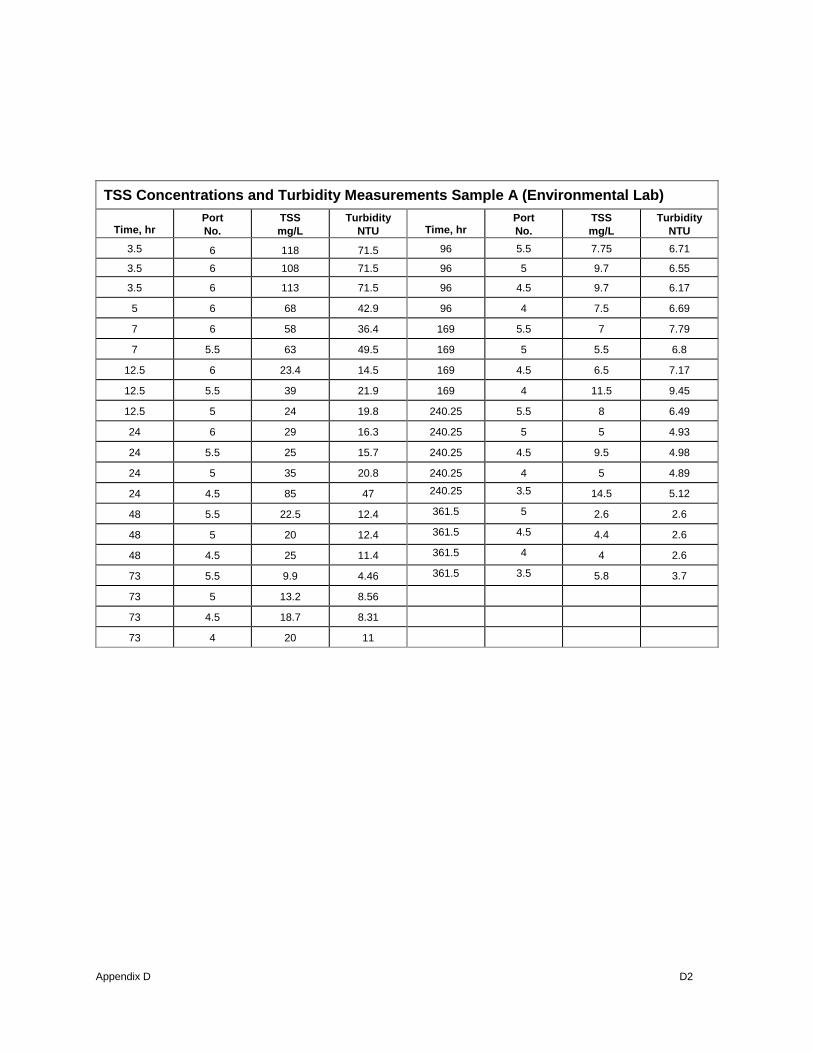
TSS Concentrations and Turbidity Measurements Sample A (Eustis)
Time, hr Port No.
TSS mg/L
Turbidity NTU Time, hr
Port No.
TSS mg/L
Turbidity NTU
7 6 153 139 168 4.5 38.1 120
12 6 76 126 264 6 22.2 41.3
12 5.5 76 139 264 5.5 27 36.9
24 6 67 110 264 5 70.9 61.1
24 5.5 76 105 264 4.5 41.7 58.7
24 5 134 119 264 4 44 23.5
48 6 64 133 360 5.5 15.4 25.3
48 5.5 62 138 360 5 47.8 50.7
48 5 73 132 360 4.5 40 47.9
72 6 32 84 360 4 44.3 73.9
72 5.5 57 131
72 5 71 140
72 4.5 158 255
96 6 35 102
96 5.5 41 137
96 5 96 94
96 4.5 66 100
168 6 32.67 52
168 5.5 46 79
168 5 85.5 103
Appendix D D2
TSS Concentrations and Turbidity Measurements Sample A (Environmental Lab)
Time, hr Port No.
TSS mg/L
Turbidity NTU Time, hr
Port No.
TSS mg/L
Turbidity NTU
3.5 6 118 71.5 96 5.5 7.75 6.71
3.5 6 108 71.5 96 5 9.7 6.55
3.5 6 113 71.5 96 4.5 9.7 6.17
5 6 68 42.9 96 4 7.5 6.69
7 6 58 36.4 169 5.5 7 7.79
7 5.5 63 49.5 169 5 5.5 6.8
12.5 6 23.4 14.5 169 4.5 6.5 7.17
12.5 5.5 39 21.9 169 4 11.5 9.45
12.5 5 24 19.8 240.25 5.5 8 6.49
24 6 29 16.3 240.25 5 5 4.93
24 5.5 25 15.7 240.25 4.5 9.5 4.98
24 5 35 20.8 240.25 4 5 4.89
24 4.5 85 47 240.25 3.5 14.5 5.12
48 5.5 22.5 12.4 361.5 5 2.6 2.6
48 5 20 12.4 361.5 4.5 4.4 2.6
48 4.5 25 11.4 361.5 4 4 2.6
73 5.5 9.9 4.46 361.5 3.5 5.8 3.7
73 5 13.2 8.56
73 4.5 18.7 8.31
73 4 20 11

Appendix D D3
TSS Concentrations and Turbidity Measurements Sample B (Eustis)
Time, hr Port No.
TSS mg/L
Turbidity NTU Time, hr
Port No.
TSS mg/L
Turbidity NTU
7 6 226 200 168 5 40.6 96
12 6 78.7 81.3 168 4.5 70.3 104
12 5.5 70 78.6 168 4 140 142
12 5 206 122 264 5.5 23.7 61.1
24 6 74.3 101 264 5 29.5 77.3
24 5.5 77 87.2 264 4.5 27.8 60
24 5 83 108 264 4 76.9 79.1
24 4.5 100 109 264 3.5 217 119
48 5.5 44 83.5 360 5.5 17.4 45.8
48 5 64 90 360 5 21.7 53.3
48 4.5 69.2 84.3 360 4.5 30.4 43
72 5.5 45 78.6 360 4 124 45.2
72 5 54 89.2 360 3.5 159 99.6
72 4.5 51.1 77.1
72 4 148 111
96 5.5 38 97.5
96 5 54 84.8
96 4.5 41.9 91.3
96 4 87.6 121
168 5.5 30 86.6
Appendix D D4
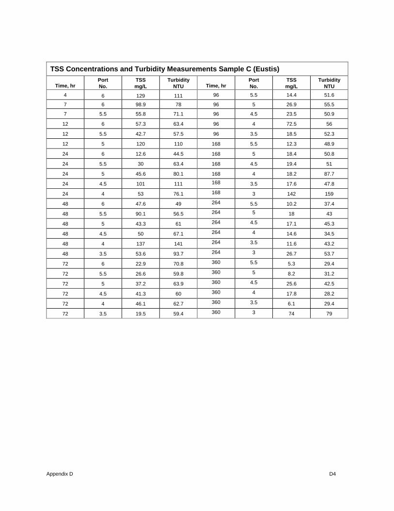
TSS Concentrations and Turbidity Measurements Sample C (Eustis)
Time, hr Port No.
TSS mg/L
Turbidity NTU Time, hr
Port No.
TSS mg/L
Turbidity NTU
4 6 129 111 96 5.5 14.4 51.6
7 6 98.9 78 96 5 26.9 55.5
7 5.5 55.8 71.1 96 4.5 23.5 50.9
12 6 57.3 63.4 96 4 72.5 56
12 5.5 42.7 57.5 96 3.5 18.5 52.3
12 5 120 110 168 5.5 12.3 48.9
24 6 12.6 44.5 168 5 18.4 50.8
24 5.5 30 63.4 168 4.5 19.4 51
24 5 45.6 80.1 168 4 18.2 87.7
24 4.5 101 111 168 3.5 17.6 47.8
24 4 53 76.1 168 3 142 159
48 6 47.6 49 264 5.5 10.2 37.4
48 5.5 90.1 56.5 264 5 18 43
48 5 43.3 61 264 4.5 17.1 45.3
48 4.5 50 67.1 264 4 14.6 34.5
48 4 137 141 264 3.5 11.6 43.2
48 3.5 53.6 93.7 264 3 26.7 53.7
72 6 22.9 70.8 360 5.5 5.3 29.4
72 5.5 26.6 59.8 360 5 8.2 31.2
72 5 37.2 63.9 360 4.5 25.6 42.5
72 4.5 41.3 60 360 4 17.8 28.2
72 4 46.1 62.7 360 3.5 6.1 29.4
72 3.5 19.5 59.4 360 3 74 79
Appendix D D5
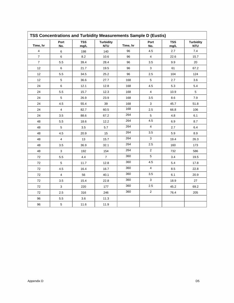
TSS Concentrations and Turbidity Measurements Sample D (Eustis)
Time, hr Port No.
TSS mg/L
Turbidity NTU Time, hr
Port No.
TSS mg/L
Turbidity NTU
4 6 198 140 96 4.5 2.7 7.4
7 6 8.2 10.6 96 4 22.6 15.7
7 5.5 39.4 28.4 96 3.5 9.9 20
12 6 21.7 19.5 96 3 61 67.2
12 5.5 34.5 25.2 96 2.5 104 124
12 5 36.6 27.7 168 5 2.7 3.6
24 6 12.1 12.8 168 4.5 5.3 5.4
24 5.5 15.7 12.3 168 4 10.9 5
24 5 26.9 23.9 168 3.5 8.6 7.9
24 4.5 55.4 39 168 3 45.7 51.8
24 4 82.7 60.5 168 2.5 66.8 106
24 3.5 88.6 67.2 264 5 4.8 6.1
48 5.5 18.6 12.2 264 4.5 6.9 8.7
48 5 3.5 5.7 264 4 2.7 6.4
48 4.5 20.9 15 264 3.5 5.9 8.9
48 4 13 15.7 264 3 19.4 26.3
48 3.5 36.9 32.1 264 2.5 160 173
48 3 192 154 264 2 732 586
72 5.5 4.4 7 360 5 3.4 19.5
72 5 11.7 12.8 360 4.5 5.4 17.8
72 4.5 16.4 16.7 360 4 8.5 22.8
72 4 56 40.1 360 3.5 6.1 20.9
72 3.5 15.4 22.8 360 3 18.9 27
72 3 220 177 360 2.5 45.2 69.2
72 2.5 316 246 360 2 76.4 205
96 5.5 3.6 11.3
96 5 11.6 11.9

Appendix D D6
Calcasieu, Sample A (ERDC), Turbidity vs. TSS
y = 0.6263xR2 = 0.9636
0
10
20
30
40
50
60
70
80
0 20 40 60 80 100 120
TSS (mg/L)
Turb
idity
(NTU
)
Calcasieu - Sample A (Eustis), TSS vs. Turbidity
y = 0.6166xR2 = 0.4719
020406080
100120140160180
0 50 100 150 200 250 300
Turbidity, NTU
Tota
l Sus
pend
ed S
olid
s,
mg/
L

Appendix D D7
Calcasieu - Sample C, TSS vs. Turbidity
y = 0.7526xR2 = 0.6416
020406080
100120140160
0 20 40 60 80 100 120 140 160 180Turbidity, NTU
To
tal
Su
spen
ded
So
lid
s, m
g/L
Calcasieu - Sample B, TSS vs. Turbidity
y = 0.9192xR2 = 0.4611
0
50
100
150
200
250
0 50 100 150 200 250
Turbidity, NTU
Tota
l Sus
pend
ed S
olid
s,
mg/
L
Appendix D D8
Calcasieu - Sample D, TSS vs. Turbidity
y = 1.1474xR2 = 0.9376
0.000100.000200.000300.000400.000500.000600.000700.000800.000
0 100 200 300 400 500 600 700
Turbidity, NTU
Tota
l Sus
pend
ed S
olid
s,
mg/
L

Appendix E E1
APPENDIX E LIDAR SURVEY SEPTEMBER 2002
Calcasieu River CDF Capacities Based Upon Lidar Survey Volume at Contour (CY)
Disp. Area
Total Acr.
App. Avg Dike
Elev. (Ft) Add. Dike Lift (Ft)
App. Disp Dike Elev.
(Ft) -2 2 4 6 8 10 12 14 16 18 20
Useable Vol. Cap. (CY)
Cap W/2:1 Bulk Fact.
Pay+Ovd Cap.
1 50 14 0 14 0 0 0 0 251,681 96,800 19,360 0 348,481
2 45 16 0 16 0 0 0 0 0 290,401 32,267 24,200 0 322,668 3
(Clooney
Island) 112 14 2 16 0 0 0 0 238,774 629,202 183,921 0 1,051,897
4 112 12 4 16 0 0 0 0 251,681 459,802 290,401 1,001,884
5 30.5 14 2 16 0 0 58,080 242,001 70,987 67,760 0 0 438,828
6 39 4 OUT OUT 0
7 255 16(front)-12(back) 2 14 0 0 0 0
1,422,966 245,228 80,667 0 -80,667 1,668,193
8 188 12 2 14 0 0 0 0 1,819,84
7 0 0 1,819,847
9 169 12(front)-8(back) 2 10 0 0 0 0 504,975 0 0 0
10 127 10(front)-8(back) 2 10 0 0 0 819,577 0 0 819,577
11 135 8 2 10 0 0 0 790,536 40,333 790,536
12A 160 8 2 10 0 0 0 1,032,53
7 0 1,032,537
12B 430
16(Flare)-12(North
End) 2 14 0 0 0 0 759,883 1,087,391 345,255 0 -41,947 1,847,274 3,670,348 1,835,174 13
(Choupique
Island) 700 16(front)-10(back) 2 12 0 0 0 0
1,516,539 645,336 0
-242,001
-225,868 1,516,539
15 180 12 4 16 0 0 0 0 529,175 1,345,525 0 1,874,701
16N 115 12 2 14 0 0 0 0 0 0 371,068 0
16S 40 20 OUT OUT 0
17* 200 8 2 10 0 0 0 0 371,068 0 0
22 135 14 2 16 0 0 0 0 0 0 580,802 145,201 580,802
23 115 16 0 16 116,160 0 0 0 0 0 96,800 177,467 0 -
48,400 -64,534 212,961
D 250 16 0 16 0 0 0 0 0 726,003 484,002 177,467 0 1,210,005 5,395,008 2,697,504
E 150 12 4 16 0 0 0 0 451,735 1,113,204 0 1,564,939 6,959,947 3,479,974
H 140 10 2 12 0 0 0 0 658,243 93,574 0 658,243
M 390 6 4 10 0 0 2,420,009 419,468 242,001 2,839,478
N 215 8(front)-6(back) 4 10 0 0 0
1,290,672 48,400 1,290,672 4,788,392 2,394,196
* Large spoils mounds with max elevations at +22'. Spoil mounds are approx. 63 acres.
18,101,67
1 9,050,835

Appendix E E2
Calcasieu River CDF Capacities Based Upon Lidar Survey Volume at Contour (CY)
Disposal Area
Add. Dike Lift
(Ft)
Appr. Disp. Dike Elev. (Ft) -2 2 4 6 8 10 12 14 16 18 20
Useable Vol. Cap. (CY)
Cap. W/2:1 Bulk Fact.
Pay+Ovd Cap.
1 0 14 0 0 0 0 41,947 108,094 141,974 156,494 161,334 161,334 161,334 150,041
2 0 16 0 0 0 0 0 48,400 104,867 125,034 141,167 145,201 145,201 153,267 3 (Clooney
Island) 2 16 0 0 0 0 29,847 164,561 315,408 361,388 361,388 361,388 361,388 509,815
4 4 16 0 0 0 0 31,460 139,554 288,788 361,388 361,388 361,388 361,388 459,802
5 2 16 0 0 4,840 33,880 66,954 87,120 98,414 98,414 98,414 98,414 98,414 291,208
6 OUT OUT 124,227 125,034 125,840 125,840 125,840 125,840 125,840 125,840 125,840 125,840 out
7 2 14 0 0 0 0 237,161 535,629 637,269 709,869 782,470 822,803 822,803 772,790
8 2 14 0 0 0 0 303,308 606,616 606,616 606,616 606,616 606,616 606,616 909,924
9 2 10 0 0 0 0 252,488 525,142 545,309 545,309 545,309 545,309 545,309 0
10 2 10 0 0 0 204,894 409,788 409,788 409,788 409,788 409,788 409,788 409,788 204,894
11 2 10 0 0 0 197,634 415,435 435,602 435,602 435,602 435,602 435,602 435,602 197,634
12A 2 10 0 0 0 258,134 516,269 516,269 516,269 516,269 516,269 516,269 516,269 258,134
12B 2 14 0 0 0 0 126,647 525,142 969,617 1,243,885 1,366,499 1,387,472 1,387,472 651,789 1,107,558 553,779 13
(Choupique Island) 2 12 0 0 0 0 379,135 1,080,938 1,653,673 2,024,741 2,202,209 2,258,675 2,258,675 379,135
15 4 16 0 0 0 0 66,147 356,548 580,802 580,802 580,802 580,802 580,802 1,003,497
16N 2 14 0 0 0 0 0 0 185,534 371,068 371,068 371,068 371,068 0
16S OUT OUT 0 0 0 0 0 0 0 32,267 96,800 129,067 out
17* 2 10 0 0 0 0 185,534 406,562 442,055 442,055 442,055 442,055 442,055 0
22 2 16 0 0 0 0 0 0 145,201 363,001 435,602 435,602 435,602 145,201
23 0 16 0 0 0 0 0 0 24,200 137,134 258,134 314,601 354,935 24,200
D 0 16 0 0 0 0 0 121,000 363,001 572,736 734,070 806,670 806,670 484,002 2,036,035 1,018,017
E 4 16 0 0 0 0 56,467 298,468 484,002 484,002 484,002 484,002 484,002 838,937 2,874,971 1,437,486
H 2 12 0 0 0 0 164,561 375,908 437,215 451,735 451,735 451,735 451,735 164,561
M 4 10 0 0 403,335 911,537 1,137,404 1,258,405 1,258,405 1,258,405 1,258,405 1,258,405 1,258,405 1,314,872
N 4 10 0 0 0 322,668 669,536 693,736 693,736 693,736 693,736 693,736 693,736 322,668 1,802,100 901,050
* Large spoils mounds with max elevations at +22'. Spoil mounds are approx. 63 acres.
9,236,369 4,618,185

Appendix E E3
Disp. Area Total Acr. App. Avg. Dike
Elev. (Ft)
Vol. at 10' (if dikes
raised)
10' Dike Cap.(12' dk,
2' fb)
Vol. at 10' (current, w/ 2' fb)
Current Cap. In Situ Dredge Vol Cap. Needed (30" dredge)
1 50 14 150,041 150,041
2 45 16 48,400 48,400
3 (Clooney Island) 112 14 194,407 194,407
4 112 12 171,014 171,014
5 30.5 14 192,794 192,794
6 39 4 out out
7 255 16(front)-12(back) 772,790 772,790
8 188 12 909,924 909,924
9 169 12(front)-8(back) 777,630 0 current dikes below 12'
10 127 10(front)-8(back) 1,024,471 204,894
11 135 8 1,048,671 197,634
12A 160 8 1,290,672 258,134
12B 430 16(Flare)-12(North End) 651,789 7,232,602 651,789 3,751,821 6,500,000 7,666,138 13 (Choupique
Island) 700 16(front)-10(back) 1,460,072 379,135
15 180 12 422,695 422,695
16N 115 12 0 0
16S 40 20 out out
17* 200 8 592,096 0
22 135 14 0 0
23 115 16 0 0
D 250 16 121,000 121,000
E 150 12 354,935 2,950,798 354,935 1,277,765 4,500,000 5,307,326
H 140 10 540,469 164,561
M 390 6 3,710,681 403,335
N 215 8(front)-6(back) 1,685,940 5,937,090 0 567,896 4,000,000 4,717,623
Total 16,120,490 16,120,490 5,597,482 5,597,482 15,000,000 17,691,088
*Estimated based on ratio of upper reach I am currently revising these numbers.

Appendix E E4

Appendix E E1