cairns thesis
DESCRIPTION
vsTRANSCRIPT
Data Logger using Raspberry Pi
Scott Cairns - 1817523
April 2013
Dissertation submitted in partial fulfilment for the degree of BSc (Hons) Computing Science
Department of Computing Science and MathematicsUniversity of Stirling
0

Abstract
The Raspberry Pi – a newly released credit card sized microcomputer – has sparked a lot of interest since its release resulting in a large amount of projects being carried out using it. This project looks at using the Raspberry Pi to create a cost efficient data logger. Data loggers are generally expensive and limit what the end user can achieve, this project allows the end user to create what they wish – what they want to record, where they want to record it – it allows the device to be expanded which no expensive data logger offers. This work researches various software packages and hardware available allowing a cost efficient data logger. The finished data logger combines the Raspberry Pi and the Gertboard with a temperature sensor, optical sensor, LEDs and a webcam and allows the user to control it both on the device and remotely. This is a simple and effective solution with scope for expansion.
1
Attestation
I understand the nature of plagiarism, and am aware of the University’s policy on this. I certify that this dissertation reports original work by me during my University project except for the following:
The ffserver configuration code in Appendix B was largely adapted from http://sirlagz.net/2012/08/04/how-to-stream-a-webcam-from-the-raspberry-pi.
The code for uploading data to COSM in the main program (Appendix E) was largely adapted from http://learn.adafruit.com/send-raspberry-pi-data-to-cosm/python-script.
The code for receiving an analogue to digital conversation value in the main program (Appendix E) was largely adapted from https://sites.google.com/a/joekamphaus.net/raspberry-pi-spi-interface-to-mcp3002/
The code for editing the terminal to allow key detection in the main program (Appendix E) was largely adapted from https://bbs.archlinux.org/viewtopic.php?pid=105189#p105189
The code for reloading the SPI drivers to prevent SPI failures (Appendix E) was largely adapted from http://www.raspberrypi.org/phpBB3/viewtopic.php?p=271375&sid=bc3f254f5c652710b9a645acc48ab771#p271375
Signature Date
2
Acknowledgements
I would like to thank my supervisor, Dr Andrew Abel. From finding an appropriate topic for the project to the writing of the thesis he has offered constant support, motivation and feedback. I would also like to thank Professor Leslie Smith for ideas during the initial proposal of the project.
3
Table of Contents
Abstract..................................................................................................................................1Attestation..............................................................................................................................2Acknowledgements...............................................................................................................3Table of Contents...................................................................................................................4List of Figures........................................................................................................................51 Introduction.....................................................................................................................6
1.1 Background and Context........................................................................................61.2 Scope and Objectives..............................................................................................71.3 Achievements.........................................................................................................71.4 Overview of Dissertation........................................................................................7
2 State-of-The-Art.............................................................................................................92.1 Hardware.................................................................................................................92.2 Commercial data loggers......................................................................................102.3 Solar Logger.........................................................................................................112.4 Garage monitor.....................................................................................................112.5 PiEye.....................................................................................................................112.6 Temperature Sensor..............................................................................................122.7 Summary...............................................................................................................12
3 Development.................................................................................................................133.1 Design...................................................................................................................13
3.1.1 Installer.........................................................................................................133.1.2 Data logger....................................................................................................13
3.2 Implementation.....................................................................................................163.2.1 Software........................................................................................................163.2.2 Hardware.......................................................................................................19
4 Testing and Evaluation.................................................................................................204.1 Testing..................................................................................................................20
4.1.1 Data logging over the network.....................................................................204.1.2 Data logging on the SD card.........................................................................204.1.3 Taking a single image...................................................................................214.1.4 Data logging with no webcam plugged in....................................................214.1.5 Single image capture with no webcam plugged in.......................................214.1.6 Using unauthorised keys...............................................................................224.1.7 Testing the optical sensor.............................................................................224.1.8 Testing the temperature sensor.....................................................................234.1.9 Using a standard user account......................................................................24
4.2 Issues and limitations............................................................................................245 Conclusion....................................................................................................................26
5.1 Conclusion............................................................................................................265.2 Future Work..........................................................................................................26
5.2.1 Portability.....................................................................................................265.2.2 Sensors..........................................................................................................275.2.3 Audio feedback.............................................................................................275.2.4 Recording software.......................................................................................27
References...........................................................................................................................28Appendix A Source code for FFServer.conf file.................................................................30Appendix B Source code for installation file......................................................................31Appendix C Software Installation guide.............................................................................32Appendix D User guide.......................................................................................................36Appendix E Source code for logger.py Program.................................................................41
4
List of Figures
Figure 1. A fully assembled Gertboard with the Pi................................................................9Figure 2. The Adafruit Pi Cobbler.......................................................................................10Figure 3. The Pi-Face Digital Interface................................................................................10Figure 4. Typical output the user will see when Data Logging...........................................16Figure 5. Outcome of first test case.....................................................................................20Figure 6. Outcome of second test case.................................................................................20Figure 7. Outcome of the third test case..............................................................................21Figure 8. Outcome of the fourth test case............................................................................21Figure 9. Outcome of the fifth test case...............................................................................22Figure 10. Outcome of the sixth test case..........................................................................22Figure 11. Outcome of the seventh test case......................................................................23Figure 12. Outcome of the eight test case..........................................................................23Figure 13. Outcome of the ninth test case..........................................................................24Figure 14. Snapshot of the top command when storing.....................................................24Figure 15. Snapshot of the top command when streaming................................................25Figure 16. List of frame formats for webcam....................................................................35Figure 17. Terminal view for changing root password......................................................37Figure 18. Terminal view for changing root password......................................................37Figure 19. Terminal view when running program.............................................................38Figure 20. Terminal view showing stream.........................................................................38Figure 21. Terminal view when beginning logging...........................................................38Figure 22. Terminal view showing store............................................................................39Figure 23. Terminal view when beginning logging...........................................................39Figure 24. List of contents within logger folder................................................................39Figure 25. Terminal view taking single image...................................................................40
5
1 Introduction
The aim of this project is to create a functional data logger using the Raspberry Pi that is capable of recording information from the webcam, microphone and various GPIO sensors such as temperature and optical sensors. This will allow the user to control the data logger using buttons connected via GPIO. The Raspberry Pi required various software packages and Python modules to be installed for the Raspbian Wheezy operating system to allow interaction with both USB devices and GPIO devices.
The project aims to allow anyone who has a spare webcam (compatible with the Pi) or microphone and a Raspberry Pi to use the software in order to create a data logging device, which could be used for things such as a cost efficient CCTV camera, recording audio information (such as notes the user may wish to hear back later). If the users have a battery pack this would enable it to be potentially used anywhere (limited only by battery life) even in extreme cases such as being used to record climbing mountains or bungee jumping. The final device will allow the user to upload the video and audio at a later date (or stream if wirelessly connected to a network). This can be extended to make use of the GPIO by including other sensors (a typical temperature sensor such as the one used in this project – the TMP36 – costs about one pound).
The project that has been undertaken is to develop a portable data logger using the newly released Raspberry Pi microcomputer. As the Raspberry Pi was newly released onset of this project (the official release was 29 February 2012) this involved research into the device, as well as any required hardware to ensure there were no compatibility issues, the operating systems available to such a device, the software available which would allow the device to interact with sensors (such as webcams and microphones) and interaction with the GPIO (General Purpose Input / Output). The GPIO is a collection of small pins on the Raspberry Pi which allows devices to be attached and controlled. The operating system can detect and configure for either input or output, and this project makes use of this to allow LEDs to be enabled and disabled for purposes of user feedback, and also allow buttons to be pressed (enabling interaction with the program and the carrying out of commands such as initialising data logging) as well as receiving sensor data (temperature and optical for this project, however many more exist) using the GPIO pins. GPIO pins can be used using various different methods; this project makes use of the newly released Gertboard15, which slots onto the GPIO pins to extend the capability of the GPIO. The Gertboard includes motor controller, dual channel digital to analogue converter, dual channel analogue to digital converter, on-board LEDs, buttons15.
1.1 Background and Context
The Raspberry Pi has received a lot of attention ever since it was first announced. Since release, many lot of people have obtained Pi’s to tinker about with and create various projects including streaming video and recording temperatures, but there appears to be a lack of all-round data loggers. A basic temperature data logger can cost between £40 and over £300, and functionality can often be limited to viewing a digital display of the current temperature or display over a limited time20. In addition it would cost over £100 for wireless webcam to stream over the network21 and even that does not include audio. This project makes use of the Raspberry Pi – a $25 Linux box22 – and a small number of accessories which includes; an optical sensor23, a temperature sensor24 and a webcam25, all of which can be purchased for under £25 to turn the Raspberry Pi into a data logger capable of recording and steaming webcam video, storing webcam video and audio and recording via text document, internet upload graphing temperature and optical sensor data in real time.
6
1.2 Scope and Objectives
The overall goal of this project was to develop a data logger using the Raspberry Pi microcomputer. The project included development of software for the Raspberry Pi using the Python programming language and a variety of modules available for the programming language to allow interaction with USB sensors (such as webcams and microphones), GPIO sensors (such as temperature sensors and optical sensors), GPIO inputs (such as buttons) and GPIO outputs (such as LEDs). This software would be used to allow the Raspberry Pi to automatically log data from hardware devices such as USB Webcams, microphones and a variety of other sensors including GPIO temperature sensors and optical sensors. It would allow users to make use of the Gertboard to press one of the three available buttons to run an appropriate command. The aims of the project also included the setting up of the Gertboard and a breadboard to allow the Raspberry Pi to interface with the GPIO with devices such as sensors, LEDs and push buttons.
The final project includes a working data logger, consisting of a Raspberry Pi connected to a Gertboard. The Gertboard is fully configured to make use of the on-board buttons and then this is also connected to a breadboard which allows multicolour LEDs and a temperature and optical sensor to be connected. The Raspberry Pi contains an SD card which holds the Raspbian Wheezy operating system and the project software; the first script ‘logger.py’ is the main software used for data logging, running this allows use of the GPIO buttons to start and end recording as well as changing the streaming method and taking a single image capture. Pressing the appropriate buttons calls a function which executes the required commands. The second item of software, ‘installation.py’, is a file to help users with installation of the data logger. It automatically downloads most of the required packages and Python modules, which allows it to be used with the installation guide to make the installation process as easy and quick as possible reducing chances of the user encountering problems due to missing software or required Python modules.
1.3 Achievements
Developments that have occurred through the duration of the project include: Learning to use Raspbian Wheezy operating system Understanding how to connect to the Raspberry Pi remotely (using SSH) Developing an understanding of Python programming language Understanding of the required packages to get the webcam to stream as well as
the command line parameters for these packages Understanding of the required packages and Python modules to interact with
GPIO and the Gertboard to obtain reading from sensors and control output Understanding of the EEML package to allow real time graphing via COSM Understanding of threading and multiprocessing in Python to allow logging of
three different sensors as well as keyboard inputs Learning how to use a breadboard, Gertboard and the electrical components used
with this (such as LEDs, buttons, sensors, capacitors, resistors) Developed a functioning data logger
The overall achievement from this project is a Raspberry Pi with the suitable software and hardware to allow it to record data from sensors; this includes two items of software one which runs the Python script to allow data logging and one to assist in the installation of the software with the installation guide.
1.4 Overview of Dissertation
The thesis contains five different chapters which explain the project, discuss how it was developed, what was required, the testing of the product and how it could be extended
7
Chapter 1 gives an introduction to the project, background and what this project has done, the goals and scope of the project and the achievements of the project. Chapter 2 contains a review of projects in the same area and how they differ from this project, including a brief description of some of the hardware used by this and similar projects. Chapter 3 provides a description of the software and hardware used to achieve the goal of creating a Data logger using the Raspberry Pi, including what each software package is used for, as well as the design of the project. Chapter 4 includes the testing of this software and product as well as detailed issues and limitations faced during this project. Chapter 5 gives the conclusion and discusses potential future work for the project.
8
2 State-of-The-Art
Although the Raspberry Pi is a relatively new device (officially released 29 February 2012) it has generated a massive amount of interest due to the low cost of the device, this has resulted in a massive amount of projects being undertaken on the Raspberry Pi in the short time it has been available.
2.1 Hardware
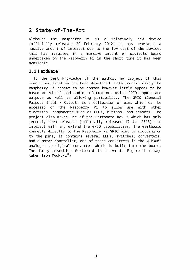
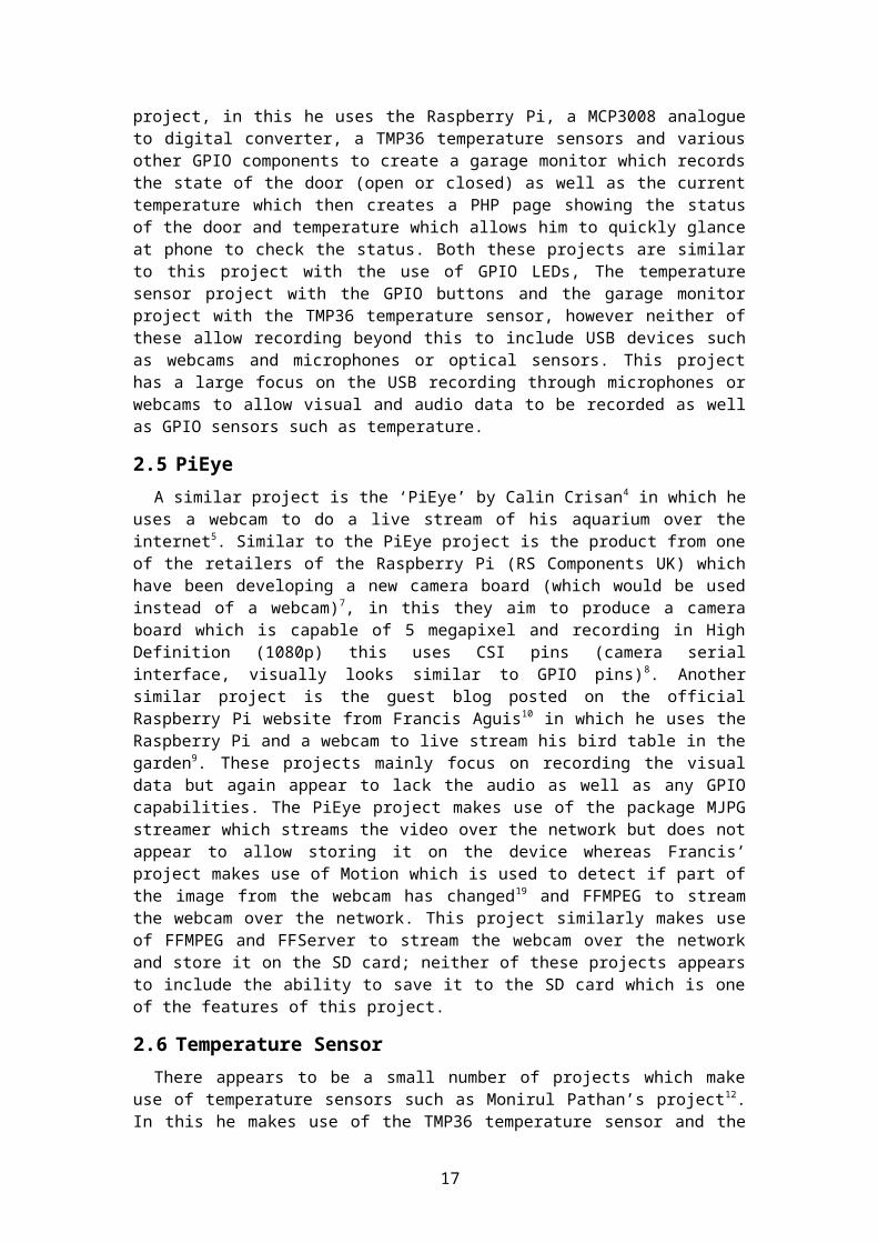
To the best knowledge of the author, no project of this exact specification has been developed. Data loggers using the Raspberry Pi appear to be common however little appear to be based on visual and audio information, using GPIO inputs and outputs as well as allowing portability. The GPIO (General Purpose Input / Output) is a collection of pins which can be accessed on the Raspberry Pi to allow use with other electrical components such as LEDs, buttons, and sensors. The project also makes use of the Gertboard Rev 2 which has only recently been released (officially released 17 Jan 2013)11 to interact with and extend the GPIO capabilities, the Gertboard connects directly to the Raspberry Pi GPIO pins by slotting on to the pins, it contains several LEDs, switches, converters, and a motor controller, one of these converters is the MCP3002 analogue to digital converter which is built into the board. The fully assembled Gertboard is shown in Figure 1 (image taken from ModMyPi32)
Figure 1. A fully assembled Gertboard with the Pi
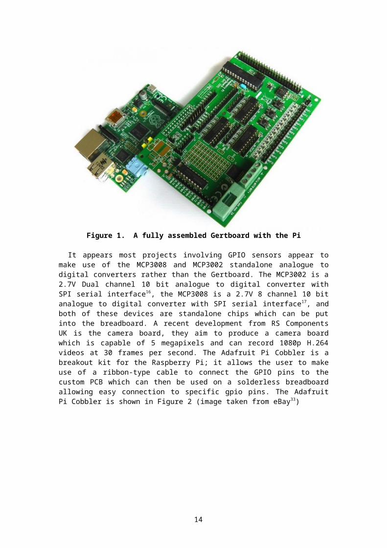
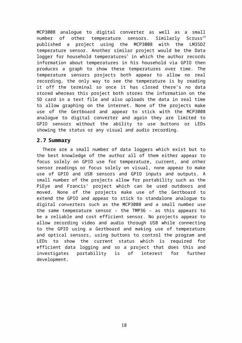
It appears most projects involving GPIO sensors appear to make use of the MCP3008 and MCP3002 standalone analogue to digital converters rather than the Gertboard. The MCP3002 is a 2.7V Dual channel 10 bit analogue to digital converter with SPI serial interface 16, the MCP3008 is a 2.7V 8 channel 10 bit analogue to digital converter with SPI serial interface17, and both of these devices are standalone chips which can be put into the breadboard. A recent development from RS Components UK is the camera board, they aim to produce a camera board which is capable of 5 megapixels and can record 1080p H.264 videos at 30 frames per second. The Adafruit Pi Cobbler is a breakout kit for the Raspberry Pi; it allows the user to make use of a ribbon-type cable to connect the GPIO pins to the custom PCB which can then
9
be used on a solderless breadboard allowing easy connection to specific gpio pins. The Adafruit Pi Cobbler is shown in Figure 2 (image taken from eBay33)
Figure 2. The Adafruit Pi Cobbler
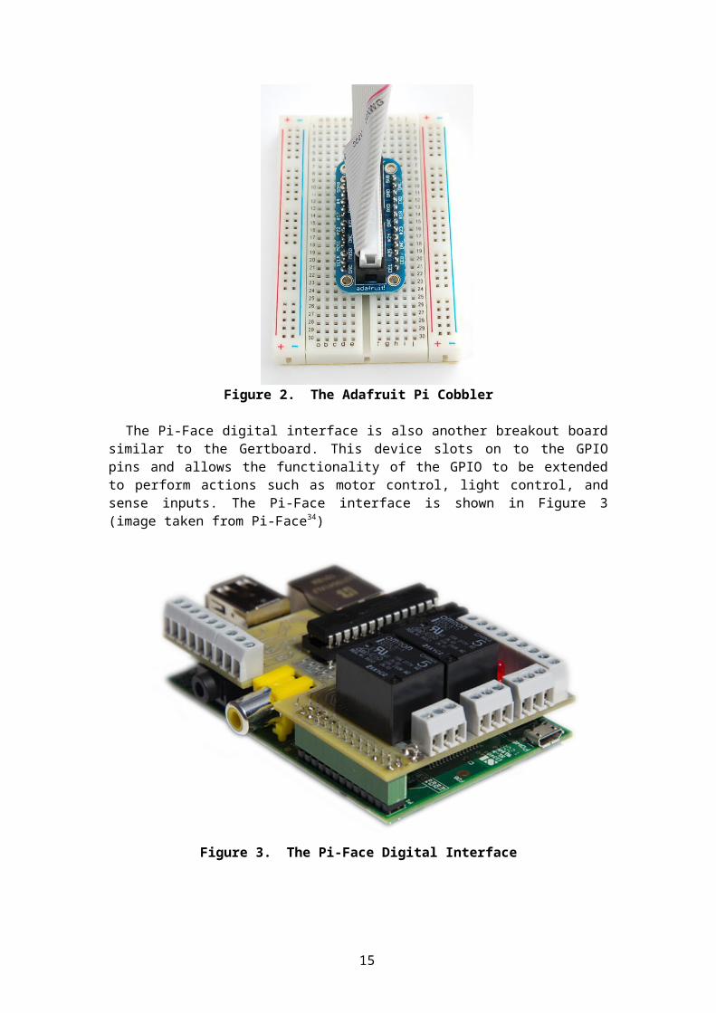
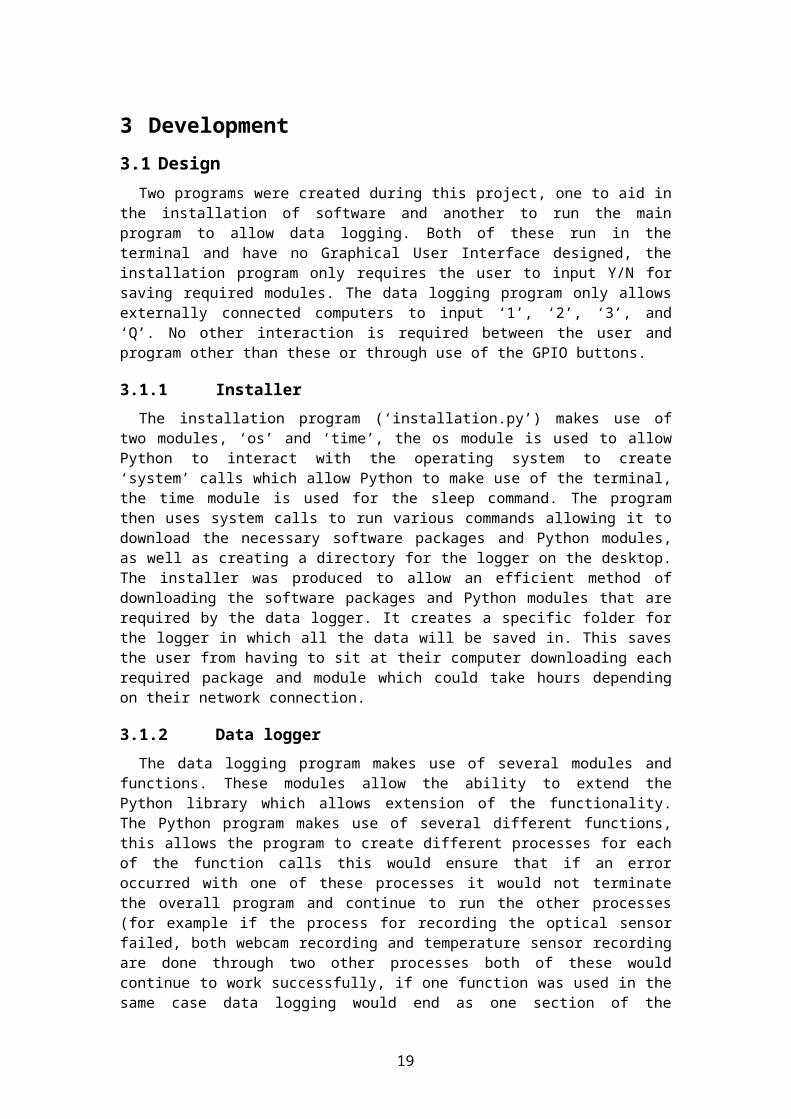
The Pi-Face digital interface is also another breakout board similar to the Gertboard. This device slots on to the GPIO pins and allows the functionality of the GPIO to be extended to perform actions such as motor control, light control, and sense inputs. The Pi-Face interface is shown in Figure 3 (image taken from Pi-Face34)
Figure 3. The Pi-Face Digital Interface
2.2 Commercial data loggers
Commercial data loggers typically focus on monitoring one sensor and tend to be very expensive; an example of a low cost temperature recorder is the MadgeTech Temp101A31. This data logger includes storage for up to 1 million temperature readings and the ability to
10
start and stop the recording. This data logger costs nearly £60 while only using one sensor. An example of a wireless data logger using temperature sensor and external sensors is the TandD RTR-574-H. This device includes two sensors which record optical and temperature readings as well as the ability to extend on this with two external sensors as well as allowing wireless connections. This data logger costs almost £380.
2.3 Solar Logger
Projects similar to the work presented in this project include Brian Dorsey’s Solar Data logger2 in this project the author connects the Raspberry Pi to various sensors such as temperature, voltage and current sensors through GPIO using this data he then records the information making it visible on his website then produces graphs showing the five temperatures and information regarding the current power usage3 as well as gas and electric meter readings18. The Solar Logger project relates to this project with the extension of the Raspberry Pi to make use of the GPIO pins to record sensor data; however this project includes GPIO buttons, GPIO LEDs and USB webcams and microphones which do not appear to be used by the Solar Logger project. The Solar Logger project also is linked to various temperature sensors placed around the house which would allow little portability as the user cannot move the Raspberry Pi without going out of range of the sensors, whereas this project allows for portability as all items are located on the board.
2.4 Garage monitor
Another similar project to this is by Matthew Kirk at the University of Cambridge, in his project he makes use of GPIO to record temperature sensors, use LEDs and buttons which is similar to this project for the use of GPIO, he builds a circuit to connect a temperature sensor then writes a program to read the sensor information and connects to the Pi via GPIO6. The temperature sensor used in this project is the DS18B20 and connects the Pi to a breadboard using the Adafruit Pi cobbler. A similar project to the temperature sensor project is include Brian Haniffin’s14 recently published project, in this he uses the Raspberry Pi, a MCP3008 analogue to digital converter, a TMP36 temperature sensors and various other GPIO components to create a garage monitor which records the state of the door (open or closed) as well as the current temperature which then creates a PHP page showing the status of the door and temperature which allows him to quickly glance at phone to check the status. Both these projects are similar to this project with the use of GPIO LEDs, The temperature sensor project with the GPIO buttons and the garage monitor project with the TMP36 temperature sensor, however neither of these allow recording beyond this to include USB devices such as webcams and microphones or optical sensors. This project has a large focus on the USB recording through microphones or webcams to allow visual and audio data to be recorded as well as GPIO sensors such as temperature.
2.5 PiEye
A similar project is the ‘PiEye’ by Calin Crisan4 in which he uses a webcam to do a live stream of his aquarium over the internet5. Similar to the PiEye project is the product from one of the retailers of the Raspberry Pi (RS Components UK) which have been developing a new camera board (which would be used instead of a webcam)7, in this they aim to produce a camera board which is capable of 5 megapixel and recording in High Definition (1080p) this uses CSI pins (camera serial interface, visually looks similar to GPIO pins)8. Another similar project is the guest blog posted on the official Raspberry Pi website from Francis Aguis10 in which he uses the Raspberry Pi and a webcam to live stream his bird table in the garden 9. These projects mainly focus on recording the visual data but again appear to lack the audio as well as any GPIO capabilities. The PiEye project makes use of the package MJPG streamer which streams the video over the network but does not appear to allow storing it on the device whereas Francis’ project makes use of Motion which is used to detect if part of the image from the webcam has changed19 and FFMPEG to stream the webcam over the network. This project similarly makes use of FFMPEG and FFServer to stream the webcam over the
11
network and store it on the SD card; neither of these projects appears to include the ability to save it to the SD card which is one of the features of this project.
2.6 Temperature Sensor
There appears to be a small number of projects which make use of temperature sensors such as Monirul Pathan’s project12. In this he makes use of the TMP36 temperature sensor and the MCP3008 analogue to digital converter as well as a small number of other temperature sensors. Similarly Scruss13 published a project using the MCP3008 with the LM35DZ temperature sensor. Another similar project would be the Data logger for household temperatures1 in which the author records information about temperatures in his household via GPIO then produces a graph to show these temperatures over time. The temperature sensors projects both appear to allow no real recording, the only way to see the temperature is by reading it off the terminal so once it has closed there’s no data stored whereas this project both stores the information on the SD card in a text file and also uploads the data in real time to allow graphing on the internet. None of the projects make use of the Gertboard and appear to stick with the MCP3008 analogue to digital converter and again they are limited to GPIO sensors without the ability to use buttons or LEDs showing the status or any visual and audio recording.
2.7 Summary
There are a small number of data loggers which exist but to the best knowledge of the author all of them either appear to focus solely on GPIO use for temperature, current, and other sensor readings or focus solely on visual, none appear to make use of GPIO and USB sensors and GPIO inputs and outputs. A small number of the projects allow for portability such as the PiEye and Francis’ project which can be used outdoors and moved. None of the projects make use of the Gertboard to extend the GPIO and appear to stick to standalone analogue to digital converters such as the MCP3008 and a small number use the same temperature sensor – the TMP36 – as this appears to be a reliable and cost efficient sensor. No projects appear to allow recording video and audio through USB while connecting to the GPIO using a Gertboard and making use of temperature and optical sensors, using buttons to control the program and LEDs to show the current status which is required for efficient data logging and so a project that does this and investigates portability is of interest for further development.
12
3 Development
3.1 Design
Two programs were created during this project, one to aid in the installation of software and another to run the main program to allow data logging. Both of these run in the terminal and have no Graphical User Interface designed, the installation program only requires the user to input Y/N for saving required modules. The data logging program only allows externally connected computers to input ‘1’, ‘2’, ‘3’, and ‘Q’. No other interaction is required between the user and program other than these or through use of the GPIO buttons.
3.1.1 Installer
The installation program (‘installation.py’) makes use of two modules, ‘os’ and ‘time’, the os module is used to allow Python to interact with the operating system to create ‘system’ calls which allow Python to make use of the terminal, the time module is used for the sleep command. The program then uses system calls to run various commands allowing it to download the necessary software packages and Python modules, as well as creating a directory for the logger on the desktop. The installer was produced to allow an efficient method of downloading the software packages and Python modules that are required by the data logger. It creates a specific folder for the logger in which all the data will be saved in. This saves the user from having to sit at their computer downloading each required package and module which could take hours depending on their network connection.
3.1.2 Data logger
The data logging program makes use of several modules and functions. These modules allow the ability to extend the Python library which allows extension of the functionality. The Python program makes use of several different functions, this allows the program to create different processes for each of the function calls this would ensure that if an error occurred with one of these processes it would not terminate the overall program and continue to run the other processes (for example if the process for recording the optical sensor failed, both webcam recording and temperature sensor recording are done through two other processes both of these would continue to work successfully, if one function was used in the same case data logging would end as one section of the function had failed). The program makes use of command line interface rather than using a graphical user interface, as the Raspberry Pi has very limited resources available this ensures no extra resources are used simply to run the GUI. With the use of GPIO buttons to allow control of the program there was simply no need for an extra GUI to be implemented, which would also require more space on the SD card allowing less recordings to be saved. Accessing the data logger remotely allows overwriting of the GPIO buttons, allowing ‘1’, ‘2’ and ‘3’ to act as buttons (B1, B2 and B3) if the user is unable to physically press the buttons then it’s still possible to run the data logger.
3.1.2.1 COSM
COSM (previously Pachube) is a service which allows users to connect to and upload sensor readings. This project makes use of EEML (Extended Environments Markup Language) which allows a connection to COSM to upload sensor reading in real-time, COSM then records the data and automatically graph the data. This allows sharing of sensor data with anyone in the world with an internet connection as well as the ability to monitor the device from anywhere in the world. COSM allows users to read and graph data stored up to three months old. COSM allows users to see webpages for individual feeds (one sensor) or view a person’s profile which includes any sensors they may upload. EEML connects to COSM using an API key, an API feed number and an API URL, using this it then sends a single reading from the sensor then COSM does the rest (updating the graphs and updating the website reading). An alternative to COSM is open.sen.se; however this appears to be an
13
invite only service for now. Open.sen.se appears to offer better graphing (use of colours, multiple figures plotted on one graph instead of a different feed for each). This project made use of COSM to create two feeds, one for the temperature sensor data and one for the optical sensor data. Using EEML this connects to COSM using the API url, key and feed number to update with real time sensor readings and graph the data.
3.1.2.2 Modules
The data logging program (‘logger.py’) makes use of eleven modules which includes ‘os’, ‘time’, ‘datetime’, ‘RPi.GPIO’, ‘spidev’, ‘multiprocessing’, ‘eeml’, ‘evdev’, ‘signal’, ‘termios’ and ‘thread’. The ‘os’ module is used by Python to allow interaction with the operating system, throughout this file it is used for various commands such as; allowing system calls similarly to the installation program (these are used to run external software packages such as ffmpeg as well as resetting the terminal on close), get an environment variable from the operating system to determine if the user is connected remotely or not, the ability to send a kill signal for a process, and reading a key press from the terminal. The ‘time’ module allows Python access to various time related functions, in this program the module has various uses which include the ability to get the current time which is then formatted and used for a timestamp on newly created files and sensor recording. It is also used to allow sleep calls which are used to allow sufficient time for reading messages, prevent buttons from being detected several times due to holding it down, and spacing out the time between processes starting. The ‘datetime’ module allows manipulation of dates which includes the format, in this program it is used to allow a string to be produced from the time integer received from the time module.
The ‘RPi.GPIO’ module allows the Python program to communicate with the GPIO pins on the Raspberry Pi, this module is used to allow gpio pins to be set up as an input or output and then attempt to detect changes such as a button press (this would change the input from 1 to 0), it is also be used to make changes such as enabling and disabling an LED, when closing the program it is also used to perform a clean-up which resets the gpio ports to defaults before the program was run. The ‘spidev’ module is used to allow the Python program to communicate with the SPI port. This is used to send and receive bits from the sensors; this allows it to read the raw values from the sensors. The ‘multiprocessing’ module is used to allow various different functions to be run concurrently; this also allows Python to terminate the processes which threading does not offer in Python. It is used to run each of the sensors individual functions when data logging begins. The ‘eeml’ module is the extended environments mark-up language which allows connection to COSM to be able to send real time sensor information.
The ‘evdev’ module is used to import UInput and ecodes. This is used to allow Python to create an input device and inject key presses, allowing a key press to end the webcam stream when connected locally. The module ‘signal’ is used with the os module to allow Python to send a kill signal for the ffmpeg process if it is running when the user wishes to begin data logging. The ‘termios’ module is used to modify the terminal that the program is running in, this gets the current terminal, modifies it to allow detection of key presses. When exiting the program the reset allows the terminal to return to its unmodified state. The ‘thread’ module is used for threading within Python. This is used for the key listener function as it does not need to be terminated during the running of the program and will run in the back waiting for a key press, threading is used rather than multiprocessing as it allows use of shared memory, this allows it to alter global variables.
3.1.2.3 Functions
The data logging program makes use of several different functions, each of these functions provide a purpose to the main section of the program. The functions in this program are ‘get_adc’, ‘recordTemp’, ‘recordLight’, ‘startRecord’, ‘stopRecord’,’ singleImg’ and
14
‘keyPress’. The ‘get_adc’ function receives a channel parameter, this function opens a spidev wrapper to communicate with the SPI port and send bits to and receive bits from the SPI channel, and this gets the output from the sensors, it then uses this raw data to return them to the function which called it.
The ‘recordTemp’ function sets up a variable using time and datetime modules to get the current timestamp, it then calls the get_adc function to receive the reading for channel 1 (temperature sensor), converts this reading to a Celsius reading and Fahrenheit then opens a file to write it to as well as sending it to COSM. The function then gets put to sleep for 30 seconds then repeats, it will repeat until the logging is cancelled or the program is closed. The ‘recordLight’ function is similar to recordTemp but calls get_adc function using the parameter 0 indicating the light sensor is on channel 0. This function just simply writes the reading value to the file and COSM without any calculations. This function again waits 30 seconds then repeats, and will repeat until logging is cancelled or the program is closed. The ‘startRecord’ function receives a ‘method’ parameter indicating the method of logging for the webcam (store or stream); the function sets up a list of parameters which allow changing of frame rates, frame size, and other important parameters. The function then gets a list of the open processes attempting to check if ffmpeg is running, if so end the process. The method variable is used to determine which code is run to store to SD card or to stream over the network, and then the appropriate variables are used within the system call.
The ‘stopRecord’ function checks if data logging is currently in process, if it is it then terminates the three processes if they are alive (a process may have terminated prior to this if it failed, for example no webcam plugged in). If locally connected it then uses evdev to create an input device and inject ‘q’ to end the webcam stream. The ‘singleImg’ function is similar to the startRecord; it sets up variables to hold information such as the frame size, input name, and other important parameters. It then checks if the ffmpeg process is running, if it is attempts to kill it then run the system call to take the image.
The ‘keyPress’ function is used to modify the terminal which allows reading of inputs. It then checks these and passes them back out of the program to be used for overwriting the buttons. This function originally posed as a problem as to start with the function was called using multiprocessing, doing this caused issues with detecting buttons and the ability to pass the key back out of the function as multiprocess functions do not share the same memory, so is unable to access global variables or return any variable from the function. This problem was overcome by using threading, threading allowed access to global variables allowing the detected key to be passed back out of the thread.
3.1.2.4 Exception handling
The functions in this program all include exception handling, each function will include a ‘try’ and ‘except KeyboardInterrupt’ which is the exception if the user presses Ctrl + C the program will end, at the same time the program will perform a system call to reset the terminal (removing the previous edits it made to allow key detection) as well as a clean-up of the gpio ports ensuring no random LEDs are left on. If the user does not cause a KeyboardInterrupt then it will be skipped.
3.1.2.5 Main section
The main section of the data logging program is an infinite loop which will wait for detection of a key or button, once either of these are detected the appropriate section of code will be executed resulting in a change to the LEDs, variables and a function call. Various sleep calls are used here to prevent several detections from one button press, again this section of code includes a ‘try’ and ‘except KeyboardInterrupt’ clause which performs the gpio clean-up and terminal reset ensuring the terminal is back to how it was before the program was run. There are various prints used throughout the program to assist the user and
15
give the user feedback to their interaction, such as recording has started and recording method has changed.
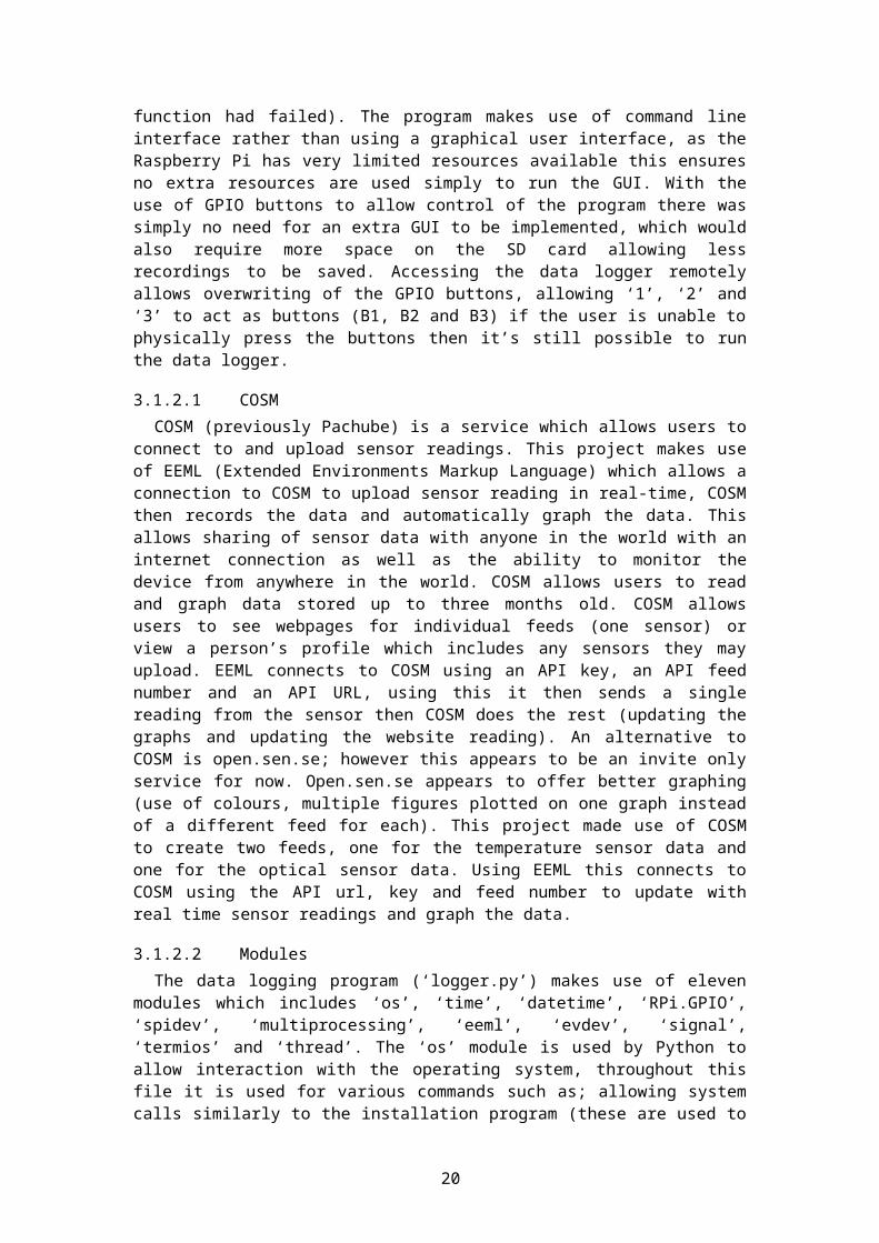
3.1.2.6 Output
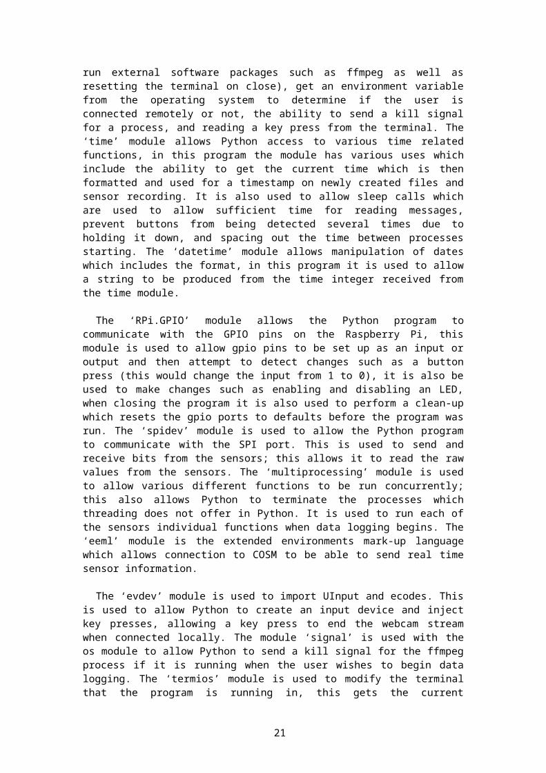
The end user will see a terminal in which any appropriate messages will appear. When the program begins the user may get a message if they are connected remotely allowing the ability to overwrite the GPIO buttons, a message will also appear stating the program has fully loaded. Enabling data logging will show another suitable warning message for users then begin data logging, during data logging every 30 seconds the temperature and optical sensors reading will be displayed. The user will receive a message when changing the streaming method between store to the SD card or stream over the network. The user will also receive a message detailing the process of an image capture. Figure 4 shows typical output the user will see when beginning the program and beginning data logging, when remotely connected.
Figure 4. Typical output the user will see when Data Logging
3.2 Implementation
To implement this project and create a data logger using the Raspberry Pi, an investigation of the available hardware and software was required.
3.2.1 Software
The project includes a variety of software packages and Python modules installed onto the Raspberry Pi to allow data logging, this includes:
Raspbian Wheezyo This is the free operating system that is based on Debian and has been
customised and optimized for use on the Raspberry Pi.o This project makes use of Raspbian Wheezy as the operating system.o It was decided that Raspbian was suitable for use as it was the most
recommended version from the Raspberry Pi Foundation and had been designed specifically for the Raspberry Pi’s hardware. Raspbian is widely supported, offers both command line and GUI, and is capable of everything required for this project
Python o The programming language used for the main software in the project, this
comes pre-installed on Raspbian Wheezy. This allows interaction with the USB (for peripherals such as webcam and microphone), GPIO (taking inputs, setting outputs) and interacts with the operating system (making use of terminal).
o This project makes use of Python as the sole programming language.
Geanyo This is a software package; Geany is a lightweight IDE (integrated
development environment) for various languages including Python.
16
o This project makes use of Geany when editing the Python code and running it from within the Raspberry Pi Graphical desktop.
FFMPEG o This is a software package that allows the Raspberry Pi to interact with the
USB webcam or microphone, it is used to capture the webcam, stream it over the network or save it on the SD card. This needs to be installed with some knowledge of the arguments used to run it (different frame rates, frame sizes, input locations, and other important parameters).
o This project allows the user to pick a method ‘store’ or ‘stream’ using this method the suitable FFMPEG code will be executed allowing a stream over the network or a video saved to the SD card. Several variables are used with this allowing the user to change the log level, frame rate, size, file format, and other important parameters.
o There are a small number of other alternatives to FFMPEG such as MEncoder and guvcview, however MEncoder appeared to have issues with the webcam settings and guvcview appeared to be designed for more of a GUI desktop rather than use in command line interfaces.
FFServer o This is a software package that allows the Raspberry Pi using FFMPEG to
stream over a network or internet allowing other devices to connect to the stream and view it. This is installed with the FFMPEG package and needs a configuration file to set some parameters (such as address port, bitrate, frame size, and other important parameters).
o This project makes use of FFServer when the logging method is set to ‘stream’ at which point ffserver will run and FFMPEG output will be set to the ip and port that FFServer is currently running on.
Fswebcam o This is a software package that allows the Raspberry Pi to capture a single
image from the webcam, this needs to be installed with some knowledge on the arguments used (again such as frame rates, frame sizes, output location, and other important parameters).
o This project allows a single image to be taken using the right button / number 3; this calls the Fswebcam code using various variables again allowing the user to set the frame size, input name, save location.
uvcdynctrl o This is a software package that allows the Raspberry Pi to configure the
webcam; this includes options such as changing this brightness, contract, hue, saturation, sharpness, and zoom. It can also be used to list all the current webcam devices detected by Raspbian, and all the formats compatible with these devices
o This project made use of the uvcdynctrl software package to receive the available frame sizes and pixel formats that can be used with this webcam, it will also allow other users to make use of the command to see the available formats for their webcams and change the variables in the code to suit.
Git o This is a software package that allows the Raspberry Pi to connect to a git
(github.com) and clone the contents of the specified git. This allows
17
software to be downloaded if it is not listed as a software package; git simply clones the contents of the git and does not install the software.
o This project makes use of Git to clone several Python modules from github which are not available through the software packages list.
Python-RPi.GPIOo This is a Python module that allows the Raspberry Pi and Python program
to communicate with the gpio pins and make use of them, this module is required to make use of LEDs and buttons that are connected via the Gertboard or directly on the GPIO pins.
o This is used within the project to set up the GPIO buttons and LEDs then further to enable/disable LEDs and listen for button presses, when exiting the program this is again used to clean up the gpio (setting it back to the default values before the program ran).
Py-Spidev o This is a Python module that allows the Raspberry Pi and Python program
to communicate with SPI devices as the Python-RPi.GPIO module currently does not allow interfacing with SPI devices.
o This is used within the project to communicate with sensors, this allows Python to communicate with an SPI port, open a channel, send a signal and receive a signal and make use of the received signal to get the current reading on the sensors.
Python-dev o This is a Python module that needs to be installed to allow Python-
RPi.GPIO to be installed correctly.o This is used during installation to allow the other Python module to be
installed and ran.
SetupTools o This is a Python module again that needs to be installed to assist another
module; this is required for the EEML installation.o Again this is used during installation to allow EEML to be installed and
run correctly.
Python-EEML o This is a Python module that’s used to communicate over the internet with
COSM (previously Pachube) which allows real time uploading of data and graphing.
o This module is used within the project to allow the Python code to send the sensor data to COSM using the API URL and API Key provided during COSM registration, this also allows a data format to be set or send raw data, in the project temperature is sent using Celsius and optical sensor sent using raw data.
Python-evdev o This is a Python module that’s used to allow Python to create an input
device and allow input events to be placed directly into the system.o This module is used within the project to create an input device then inject
the key event ‘q’ into it, used when ending the data logging to allow the webcam stream to end.
18
3.2.2 Hardware
The hardware that is currently used within the project includes: Raspberry Pi – The currently used Raspberry Pi is the Model B Revision 1 version
meaning it is limited to 256MB RAM whereas the new Revision 2 contains 512MB of ram. It also contains a 700MHz CPU, 2 USB 2.0 ports, Composite RCA, HDMI, DSI, 10/100 Ethernet and 5v MicroUSB power source.
SD card – An SD card is used to run the Raspbian Wheezy operating system with all the software packages and Python modules installed as well as the two Python programs to install and run the data logger.
Microsoft LifeCam VX-2000 – This Microsoft webcam is used for visual and audio data (using the inbuilt microphone), this is not a verified peripheral however testing of this peripheral revealed no issues with functionality, and so it was deemed suitable for use26.
Gertboard – This project makes use of the Fully Assembled Gertboard Rev 2 which slots directly on to the Raspberry Pi’s GPIO pins to extend its functionality, this is set up to allow use of the 3 on-board buttons and using the on-board MCP3002 to connect to the optical and temperature sensor located on the breadboard, it also supplies 3V3 and GND to the breadboard as well as the appropriate GPIO pins.
Breadboard – This is used to connect the LEDs and sensors to the Gertboard and supply power to them.
TMP36 – This is the temperature sensor used in the project; it is a low voltage sensor that records between -40°C to +125°C27. This is connected to the Gertboards on-board analogue to digital converter to allow a digital reading within Python.
TSL250 – This is the optical sensor used in the project, it is a low power light-to-voltage optical sensor. This is connected to the Gertboards on-board analogue to digital converter to allow a digital reading within Python.
Electrical components – Various other electrical components are used such as a green, red and yellow LED, 0.1uF ceramic disc capacitors and resistors to allow accurate readings and limit power to electrical components.
19
4 Testing and Evaluation
4.1 Testing
The testing done on this project will include the use of Scenario testing. Scenario testing is a testing method which makes use of hypothetical stories as the test cases, these scenarios attempt to replicate what the end user wishes to use the software for. Scenario testing will use a list of scenarios and ensure that each part of the program has run with various different cases. These test cases will run through every bit of code in the program ensuring there are no issues with coding.
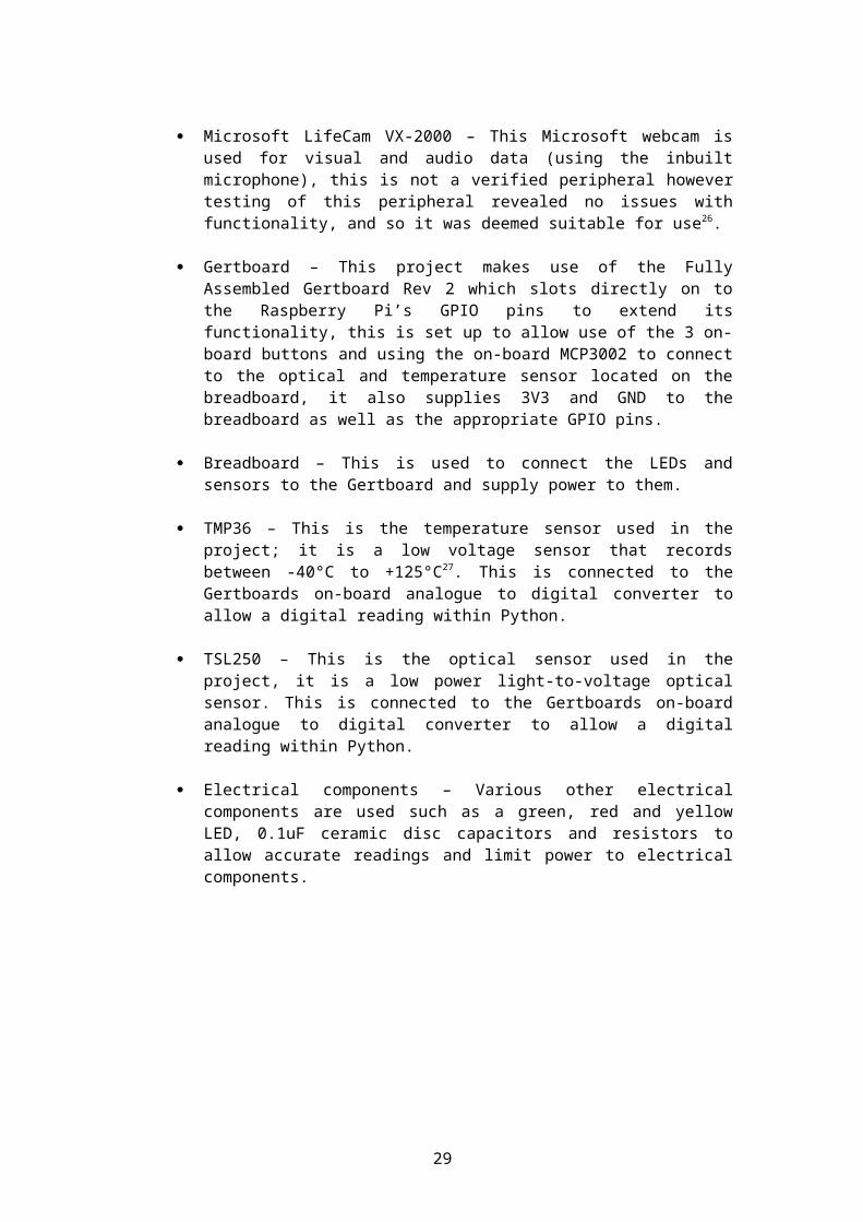
4.1.1 Data logging over the network
Test case – Enabling data logging, streaming webcam feed over the networko In this test case, the goal was to enable data logging and stream the
webcam feed over the network. To do this it required changing the logging method and starting the logging.
Test steps – Run the program, press the middle button (or 2), press the left button (or 1)
Expected results – The program should show information then start streaming over the network with the ability to connect to it via VLC
Result – Pass, as expected (Figure 5)
Figure 5. Outcome of first test case
4.1.2 Data logging on the SD card
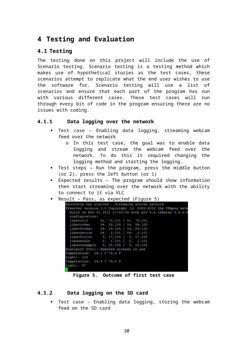
Test case – Enabling data logging, storing the webcam feed on the SD cardo In this test case, the goal was to enable data logging and store the webcam
feed on to the SD card. To do this it required starting the logging. Test steps – Run the program, press the left button (or 1) Expected results – The program should show information then start recording to
the SD card Result – Pass, as expected (Figure 6)
Figure 6. Outcome of second test case
20
4.1.3 Taking a single image
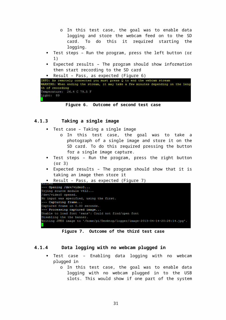
Test case – Taking a single imageo In this test case, the goal was to take a photograph of a single image and
store it on the SD card. To do this required pressing the button for a single image capture.
Test steps – Run the program, press the right button (or 3) Expected results – The program should show that it is taking an image then store it Result – Pass, as expected (Figure 7)
Figure 7. Outcome of the third test case
4.1.4 Data logging with no webcam plugged in
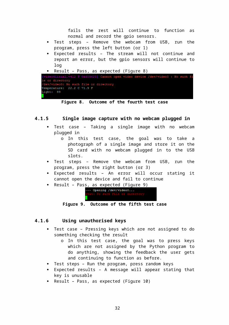
Test case – Enabling data logging with no webcam plugged ino In this test case, the goal was to enable data logging with no webcam
plugged in to the USB slots. This would show if one part of the system fails the rest will continue to function as normal and record the gpio sensors.
Test steps – Remove the webcam from USB, run the program, press the left button (or 1)
Expected results – The stream will not continue and report an error, but the gpio sensors will continue to log
Result – Pass, as expected (Figure 8)
Figure 8. Outcome of the fourth test case
4.1.5 Single image capture with no webcam plugged in
Test case – Taking a single image with no webcam plugged ino In this test case, the goal was to take a photograph of a single image and
store it on the SD card with no webcam plugged in to the USB slots. Test steps – Remove the webcam from USB, run the program, press the right
button (or 3) Expected results – An error will occur stating it cannot open the device and fail to
continue Result – Pass, as expected (Figure 9)
Figure 9. Outcome of the fifth test case
21
4.1.6 Using unauthorised keys
Test case – Pressing keys which are not assigned to do something checking the result
o In this test case, the goal was to press keys which are not assigned by the Python program to do anything, showing the feedback the user gets and continuing to function as before.
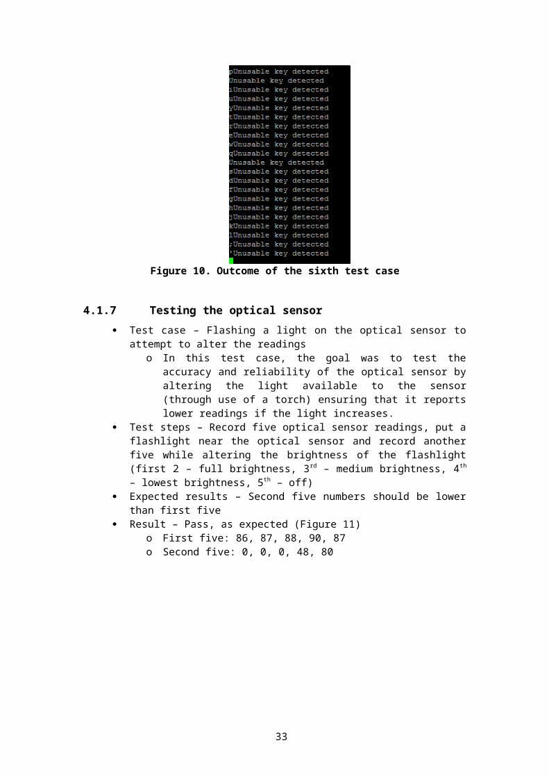
Test steps – Run the program, press random keys Expected results – A message will appear stating that key is unusable Result – Pass, as expected (Figure 10)
Figure 10. Outcome of the sixth test case
4.1.7 Testing the optical sensor
Test case – Flashing a light on the optical sensor to attempt to alter the readingso In this test case, the goal was to test the accuracy and reliability of the
optical sensor by altering the light available to the sensor (through use of a torch) ensuring that it reports lower readings if the light increases.
Test steps – Record five optical sensor readings, put a flashlight near the optical sensor and record another five while altering the brightness of the flashlight (first 2 – full brightness, 3rd – medium brightness, 4th – lowest brightness, 5th – off)
Expected results – Second five numbers should be lower than first five Result – Pass, as expected (Figure 11)
o First five: 86, 87, 88, 90, 87o Second five: 0, 0, 0, 48, 80
22
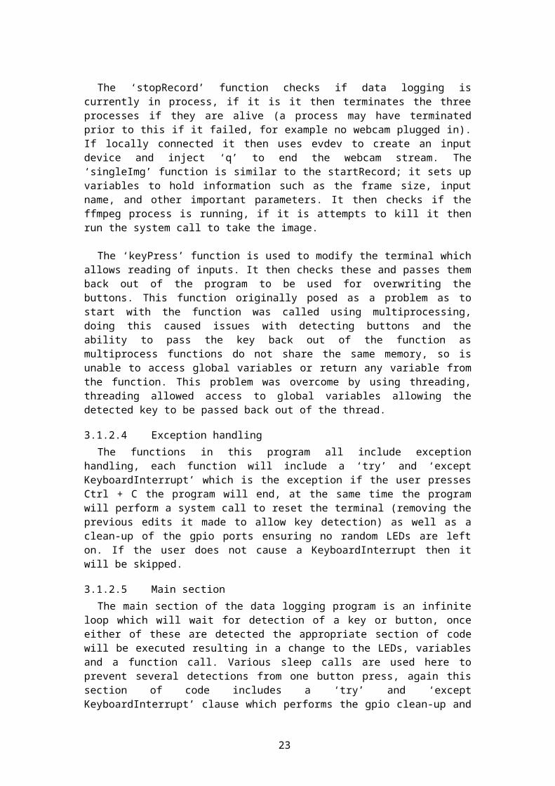
Figure 11. Outcome of the seventh test case
4.1.8 Testing the temperature sensor
Test case – Place freezing item next to temperature sensor to attempt to alter the readings
o In this test case, the goal was to test the accuracy and reliability of the temperature sensor by altering the temperature around the sensor (using a frozen item), ensuring that it reports a lower temperature when the item is next to it than prior to it being there.
Test steps – Record five temperature sensor readings, put a frozen item next to the temperature sensor and record another five
Expected results – Second five numbers should be considerably lower than the first five
Result – Pass, as expected (Figure 12)o First five: 17.0, 17.0, 17.0, 17.0, 17.7o Second five: 10.9, 10.9, 9.3, 9.0, 8.7
Figure 12. Outcome of the eight test case
23
4.1.9 Using a standard user account
Test case – Running the data logger with a standard user (not root) who has no access to specific parts of the system that is required for data logging
o In this test case, the goal was to use a standard user account to attempt to run the data logger which requires root access.
Test steps – Log into the Pi using ‘pi’ user, run the program Expected results – Inability to access GPIO Result – Pass, as expected (Figure 13)
Figure 13. Outcome of the ninth test case
4.2 Issues and limitations
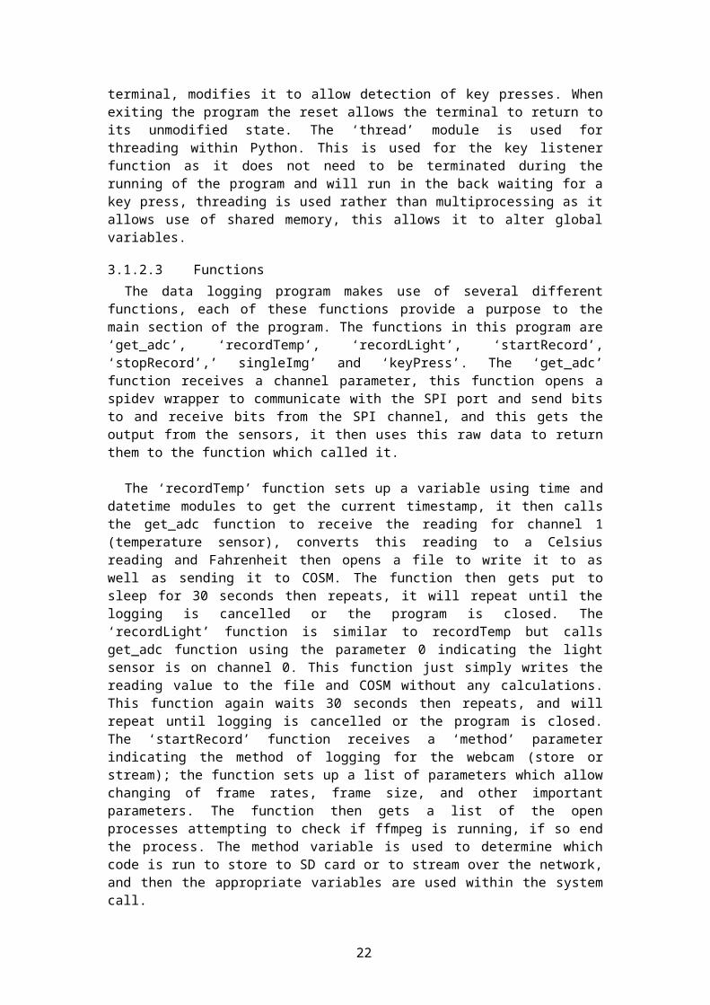
Throughout the project the main issue / limitation was down to the CPU. The Raspberry Pi runs on an ARM1176JZF-S30 (armv6k) 700 MHz Processor (which can dynamically increase up to 1 GHz). The software used to record video and audio from the webcam however, appeared to use most of the CPU when storing to the SD card
Figure 14. Snapshot of the top command when storing
A snapshot (Figure 12) shows the ‘top’ command running on the Raspberry Pi. This shows the top CPU processes as well as other information such as the CPU % and the memory usage. Running the program recording the webcam stream to the SD card results in the CPU running at typically 100%, with only three processes running in this figure the CPU usage is at 100% (90.7% used on user mode and 9.3% used by system). FFMPEG is taking up 56.2% of that, it appears when ffmpeg is running using so much of the CPU it has issues recording both visual and audio data from the webcam, which results in an ALSA buffer xrun error being shown in the terminal. When streaming the webcam video over the network the ffmpeg appears to take up a fraction of the resources it is using for video and audio
24
Figure 15. Snapshot of the top command when streaming
A snapshot (Figure 13) shows the top command again, this time it is similarly running at 100% CPU usage (98.1% by user and 1.9% by system), however this time the ffmpeg process appears to only be using a fraction of the CPU usage it was when storing to the SD card, reducing from 56.2% to 3.9%. It would appear attempting to capture visual and audio data using the Raspberry Pi will struggle due to the CPU and result in the ALSA buffer xrun errors, although it will still record with these during play back of the video file it will appear to skip a frame when each of the errors occurs.
Several other packages were tested such as MEncoder and guvcview, MEncoder attempts to do the same as ffmpeg does but similarly frame drops still occurred, a lower video quality was created, and had issues with the webcam used for this project. Guvcview appears more preferred for graphical interface rather than over a command line interface resulting in little use for this project. Removing audio from the data logging appeared to allow ffmpeg to run fine when storing it to the SD card. It would definitely appear that it is a limitation of the CPU, and appears to be attempting to record too much data which is causing random skipping of frames. Although the error exists the output file is not corrupt and still usable, at a cost of a few frames based on the length of the recording.
Similarly with the previous problem, when FFMPEG ends the streaming and storing it to the SD card it can take some time to finish encoding the audio, which resulted in the need to implement code to kill the previous process when starting a new process if it was still running. The time for encoding the audio is typically instant or a few seconds and can vary by the length of the video or the amount of audio information stored, however in some tests this was taking over ten minutes to fully encode and end the process. During which would not allow the user to start a new stream as the process is already running, implementation of this code will kill the previous ffmpeg process (meaning the audio in the file may be corrupt or not complete) and allow the new process to start. This could again be a limitation caused by the lack of processing power to allow the encoding of the file.
25
5 Conclusion
5.1 Conclusion
The goal of this project was to create a functional data logger using the Raspberry Pi, which would involve developing of software to make this possible. The data logger would allow the data to be stored locally as well as the possibility of it being sent across the network/internet. The project would make use of both USB and GPIO sensors to allow logging and allow control of the device through GPIO.
The author believes the goal has been met with this project, the final product is a functioning data logger allowing recording of temperature, optical data as well as streaming, storing and single image capture from the webcam. Users have the ability to control the device through the GPIO buttons and receive feedback on their actions via the GPIO LEDs.
The project includes the development of two items of software, an installer and the logger. This software allows a user to set up their own data logger, the logger allows remote access to control it or be controlled via buttons on the GPIO, this will run commands allowing the stream to start, method to change, and single image capture. The data logging makes use of the online service COSM to create real-time graphs using the sensor data. The user can make use of the user guides and installation guides created for this software to assist them in using it.
The project mainly went according to plan creating the data logger; however a few issues were encountered. Although the storing to SD card with audio does not work as intended due to the limitation, removal of audio would allow a fully functioning data logger with no errors caused by audio or CPU limitations. This project has successfully allowed for a low cost data logger to be produced with the ability to be used in the real world with various different uses and the ability to extend on the data loggers functionality such as portability and additional sensors.
5.2 Future Work
The work done so far in this project has allowed for development of a functioning data logger however this can be extended in various areas to improve the data logger.
5.2.1 Portability
The first major improvement would be portability; this was initially one of the planned goals for this project however due to time this was unable to be researched sufficiently and implemented, to extend the data logger to include portability this would involve the purchasing of a 5V regulated output external battery pack which is compatible with the Raspberry Pi, eLinux contains a list of verified peripherals which includes working external battery packs of which its users have tested and commented on28. TeckNet iEP392 Dual-Port 12,000 mAh External Power Bank appears to be the most favoured choice for external battery packs, with reported use of up to 16.5 hours before requiring a recharge, although this would be reduced due to the amount of power being used to stream/save webcam footage it would still allow quite a few hours of portable data logging which could be useful for outdoor trips. To allow portability it would also include purchasing a USB WiFi adapter to allow EEML to connect to COSM for graphing as well as network streaming if required, these typically require more power than a standard Raspberry Pi USB port provides so may be required to use an externally powered USB hub, alternatively the EW-7811Un from Edimax works without the need for an externally powered USB hub and should work with the webcam in one USB port and this adapter in the other, the EW-7811Un also appears to be the only WiFi
26
adapter that is instantly recognized by the Raspbian Wheezy operating system (as of 2012-09-18 version) so should be a simple installation just editing the SSID and key29.
5.2.2 Sensors
Another area for extension is sensors, although currently the Gertboard only has a two channel analogue to digital converter, this can be resolved by making use of MCP3004 or MCP3008 analogue to digital converters, allowing 4 channel and 8 channel respectively. This would allow for addition sensors (two to six) to be used with the data logger. Each sensor would simply need a new function to retrieve the data then make use of it (print it, store it then send it to COSM), there are various sensors available on the market such as sound, proximity, location/GPS, movement, touch, humidity, radiation, pressure, biometric, infrared, weather, and countless others. There are hundreds if not thousands of sensors available to implement onto the data logger which would increase the usefulness of the data logger as it has the ability to record even more relevant data than before, it would also increase the gap between this and any other data logger as they typically stick to very few different sensors.
5.2.3 Audio feedback
The product can be extended to include some form of output possibly via audio feedback such as a buzzer, this could be used for various situations such as warnings to the user, for example if the temperature is very low, if the proximity to something is very close and the users speed is enough to impact, if there’s any errors with the program such as faulty sensor data. It would also be used to give audio feedback to button presses and an action taken, such as beginning to record rather than relying solely on the green and red LEDs, i.e. if the data logger is in a place that is hard to see the user may not know if they have successfully enabled recording or not without the ability to see the data logger.
5.2.4 Recording software
Another improvement is the webcam recording software, currently the FFMPEG software makes use of the full CPU which in turn limits its ability to successfully record both visual and audio data in the case it is storing it to the SD card, this can cause an issue when recording from the webcam and in turn an error appears. The only similar software to this that’s Raspbian Wheezy / Raspberry Pi friendly appears to be MEncoder which has issues with the webcam used within this project, further research could be done into how to reduce the CPU load that ffmpeg requires to possibly fixing the issue, if it is possible.
27
References
[1] Raspberry Pi data logger, http://neilbaldwin.net/blog/weather/raspberry-pi-data-logger/, November 2012
[2] Raspberry Pi Solar Data logger, http://www.briandorey.com/post/Raspberry-Pi-Solar-Data-Logger.aspx, July 2012
[3] Home Solar PV and Water Current Report, http://home.briandorey.com/, November 2012[4] PiEye – streaming webcam in JPG format with Raspberry Pi,
http://www.bobtech.ro/tutoriale/raspberry-pi/78-streaming-webcam-in-format-m-jpg-cu-raspberry-pi, September 2012
[5] PiEye, http://pieye.dnsdynamic.com:8080/?action=stream, November 2012[6] University of Cambridge – Computer Laboratory: Raspberry Pi Temperature Sensor,
http://www.cl.cam.ac.uk/freshers/raspberrypi/tutorials/temperature/, November 2012[7] Raspberry Pi – Camera board, http://www.raspberrypi.org/archives/2555, November
2012[8] YouTube - Raspberry Pi Camera, http://www.youtube.com/watch?v=8N7kgtL0-Ts,
November 2012[9] Raspberry Pi – Guest blog #7 Bird table webcam by Francis Agius,
http://www.raspberrypi.org/archives/2504, November 2012[10] Raspberry Pi – Bird table webcam,
http://www.raspberrypi.org/wp-content/uploads/2012/11/Robin.avi, November 2012.[11] Assembled Gertboard for Raspberry Pi – Element14,
http://www.element14.com/community/docs/DOC-51726/l/assembled-gertboard-for-raspberry-pi, January 2013
[12] Raspberry Pi + Temperature Sensors, http://monirulpathan.com/afterhours/raspberry-pi-temperature-sensors/, September 2012
[13] Simple ADC with the Raspberry Pi, http://scruss.com/blog/2013/02/02/simple-adc-with-the-raspberry-pi/, February 2013
[14] My Raspberry Powered Garage Monitor, http://brianhanifin.com/2012/11/raspberry-pi-garage-monitor/, November 2012
[15] Assembled Gertboard for Raspberry Pi, http://www.element14.com/community/docs/DOC-51726/l/assembled-gertboard-for-raspberry-pi, January 2013
[16] Microchip MCP3002 user manual, http://ww1.microchip.com/downloads/en/DeviceDoc/21294C.pdf, April 2013
[17] Microchip MCP 3004/8 user manual, http://ww1.microchip.com/downloads/en/DeviceDoc/21295d.pdf, April 2013
[18] Home Solar PV and Water Current Report – Gas and Electric meter readings, http://home.briandorey.com/meter/default.aspx, April 2013
[19] Motion – Web Home, http://www.lavrsen.dk/foswiki/bin/view/Motion, February 2011[20] Data Loggers | Datalogging | Data Acquisition | Datalogger -
http://www.loggershop.co.uk/, April 2013[21] CnM Secure Wireless Camera Kit at Argos.co.uk -
http://www.argos.co.uk/webapp/wcs/stores/servlet/Browse?storeId=10151&langId=110&catalogId=23051&mRR=true&q=CCTV&c_1=1%7Ccategory_root%7CHome+and+garden%7C33005908&r_001=3%7CCamera+type%7CCMOS+wireless%7C1, April 2013
[22] Raspberry Pi - http://www.raspberrypi.org/, April 2013[23] TSL250R-LF – TAOS – PHOTODIODE, SENSOR, L/VOLTS,
http://uk.farnell.com/jsp/displayProduct.jsp?sku=1182346&action=view&CMP=GRHB-FINDCHIPS1-1004321, April 2013
[24] TMP36 – Temperature Sensor – SparkFun Electronics, https://www.sparkfun.com/products/10988, April 2013
28
[25] Microsoft Webcam: LifeCam VX-800 | Microsoft Hardware, http://www.microsoft.com/hardware/en-gb/p/lifecam-vx-800, April 2013
[26] RPi VerifiedPeripherals – eLinux, http://elinux.org/RPi_VerifiedPeripherals, April 2013[27] TMP36 Datasheet and product info | Voltage Output Temperature Sensors,
http://www.analog.com/en/mems-sensors/digital-temperature-sensors/tmp36/products/product.html, April 2013
[28] RPi VerifiedPeripherals – eLinux, http://elinux.org/RPi_VerifiedPeripherals#Working_external_Battery_packs_.28with_5.C2.A0V_regulated_output.29, April 2013
[29] RPi VerifiedPeripherals – eLinux, http://elinux.org/RPi_VerifiedPeripherals#Working_USB_Wi-Fi_Adapters, April 2013
[30] Raspberry Pi – Wikipedia, http://en.wikipedia.org/wiki/Raspberry_Pi, April 2013[31] MadgeTech Temp101A – Miniature Temperature Data Logger,
http://www.loggershop.co.uk/madgetech/temp101a-temperature-data-logger/prod_532.html, April 2013
[32] Gertboard Kit – Fully Assembled, https://www.modmypi.com/raspberry-pi-fully-assembled-gertboard, April 2013
[33] Raspberry Pi Cobbler GPIO Super Starter Kit, http://www.ebay.co.uk/itm/Raspberry-Pi-Cobbler-GPIO-Super-Starter-Kit-Breadboard-Cable-LEDs-Switches-/181071750824, April 2013
[34] Pi-Face Interface for Raspberry Pi, http://pi.cs.man.ac.uk/interface.htm, April 2013
29
Appendix A Source code for FFServer.conf file
This appendix provides the source code for the ffserver.conf file; it contains the information used for the network stream of the webcam and allows configuration of the ffserver, this configuration results in an mjpeg stream with a resolution of 352x288. The file is used when running ffserver.
Port 8001BindAddress 0.0.0.0MaxClients 10MaxBandwidth 50000NoDaemon
<Feed webcam.ffm>file /tmp/webcam.ffmFileMaxSize 10M</Feed>
<Stream webcam.mjpeg>Feed webcam.ffmFormat mjpegVideoSize 352x288VideoFrameRate 10VideoBitRate 20000VideoQMin 2VideoQMax 31</Stream>
30
Appendix B Source code for installation file
This appendix contains the source code for the installation.py file which is used to retrieve the Python modules and software required for the program.
#********************************************************************## Name: installation.py ## Description: Python program for installation of the Python modules/software required for logger.py file ## OS: Raspbian ## Author: Scott Cairns ## Notes: Used with the User Installation Guide ##*************************************************************************#
import os # import os to use for system callsimport time # for sleeps
print 'WARNING: This could take a while, installing latest packages may take a while'print 'FFMPEG will take a while to compile'time.sleep(2) # give time to read warning
os.system("sudo apt-get update") # download latest package list showing new versions of packages
os.system("sudo apt-get upgrade") # install the latest versions
if not os.path.exists("logger"): # check if the logger path doesn't existos.makedirs("logger") # if so, create it
os.system("sudo apt-get install python-dev") # install Python dev moduleos.system("sudo apt-get install python-rpi.gpio") # install gpio moduleos.system("sudo apt-get install git") # install gitos.system("git clone git://github.com/doceme/py-spidev") # clone the github filesos.system("wget http://pypi.python.org/packages/source/s/setuptools/setuptools-0.6c11.tar.gz") # get the compressed fileos.system("tar zxvf setuptools-0.6c11.tar.gz") # get setuptools module
(req'd for eeml install)os.system("wget -O geekman-python-eeml.tar.gz https://github.com/geekman/python-eeml/tarball/master")
#get EEML moduleos.system("tar zxvf geekman-python-eeml.tar.gz") # extract itos.system("git clone git://github.com/gvalkov/python-evdev.git") # clone github filesos.system("sudo apt-get install fswebcam") # get fswebcamos.system("sudo apt-get install uvcdynctrl") # get uvcdynctrl
print "Complete! Consult the user installation guide to proceed"
31
Appendix C Software Installation guide
This appendix contains a Software Installation guide to allow end users to install the Python program and make use of the included installer; it also includes information regarding how to set up the Gertboard and breadboard.
Steps for installing the modules and software required for the Python script:
1. Copy the installation.py file to the Desktop (home/pi/Desktop) (via FTP, USB flash drive, or any preferred method).
2. (In the terminal window) run the command “cd /home/pi/Desktop”, to navigate to the correct folder.
3. Run the command “python installation.py” – This will run through the Python script, it may take some time to complete depending on the users internet connection. Once complete a message will appear to confirm it has been completed.
4. If new updates are required the user will be required to press Y/N to proceed with the installation (this may happen up to 6 times over the course of the installation)
5. Once the “Complete!” message shows up in the terminal install py-spideva. Navigate to the folder using “cd py-spidev” b. Run “sudo python setup.py install”
This will navigate into the py-spidev directory then run the setup.py file which will install the python module spidev.
6. Install setuptoolsa. Navigate to the folder using “cd /home/pi/Desktop/setuptools*” b. Run “sudo python setup.py build” c. Run “sudo python setup.py install”
Again, taking the user into the setuptools directory then running build and install on setup.py, which will install the Setuptools software.
* The exact name will vary depending on the current release version.
7. Install EEMLa. Navigate to the folder using “cd /home/pi/Desktop/geekman-python-
eeml*” b. Run “sudo python setup.py install”
This navigates the user into the geekman-python-eeml folder then running setup.py to install, which will install the EEML python module.
* The exact name will vary depending on the current release version.
8. Install evdeva. Navigate to the folder using “cd /home/pi/Desktop/python-evdev”
32
b. Run “git checkout $versiontag”c. Run “sudo python setup.py install”
This navigates the user into the python-evdev directory, uses the versiontag which updates files in the tree to match the version specified and runs setup.py to install.
9. Install FFMPEGa. FTP or log into root then edit “/etc/apt/sources.list”b. Add “deb-src http://www.deb-multimedia.org sid main” c. Add “deb http://www.deb-multimedia.org wheezy main non-free”d. Run “sudo apt-get update”e. Run “sudo apt-get install deb-multimedia-keyring”f. Remove “deb http://www.deb-multimedia.org wheezy main non-free”
from “/etc/apt/sources.list”g. Run “sudo apt-get source ffmpeg-dmo”h. Navigate to the folder using “cd ffmpeg-dmo*”i. Run “./configure”j. Run “make && make install”k. Remove “deb-src http://www.deb-multimedia.org sid main” from
“/etc/apt/sources.list”
This will download the ffmpeg files and install them, FFMPEG could take up to a few hours to install (step I and J).
10. Create the ffserver.conf file in “/etc/” – The source code for this file is contained with the documentation.
Steps for preparing the Gertboard:
1. Place one jumper on B1, B2 and B3 (2 pin slots right of C9).
2. Place one jumper on 3V3 (Note: the 3V3 jumper should be on the upper two pins above J7, not the 3V3 at the top of the board).
3. Set up SPI, place jumpers on: a. GPIO 11/SCLKb. GPIO 10 / MOSIc. GPIO 9 / MISOd. GPIO 8 / CSnA
4. Set up buttons as GPIO, place jumper cables between: a. B1 and GPIO 25b. B2 and GPIO 24c. B3 and GPIO 23
5. Place jumper cable between 3V3 (top of the board) and + on breadboard.
6. Place jumper cable between GND (right of AD1 near J28) and – on breadboard.
33
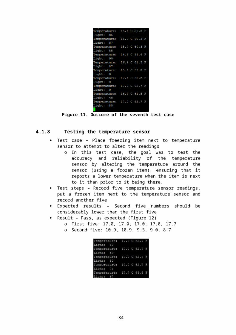
7. Set up connection to breadboard, place jumper cables between:a. GPIO 22 and long pin on green LEDb. GPIO 18 and long pin on yellow LEDc. GPIO 17 and long pin on red LEDd. AD1 and middle pin of TMP36 (Temp sensor)e. AD0 and middle pin of Optical sensor
Steps for preparing the breadboard:
1. Place 330 ohms resistors between:a. negative (GND) and the smaller pin on the green LEDb. negative (GND) and the smaller pin on the yellow LEDc. negative (GND) and the smaller pin on the red LED
2. Place jumper cables between:a. Positive (3V3) and the top pin of the temperature sensorb. Negative (GND) and the bottom pin of the temperature sensorc. Positive (3V3) and the bottom pin of the optical sensord. Negative (GND) and the top pin of the optical sensor
3. Add a .01uF capacitor to both sensors between the 3V3 and GND connections (top and bottom).
Steps for changing the webcam:
1. Log in to the Raspberry Pi using any account available (default user: pi password: raspberry)
To view the list of devices enter ‘uvcdynctrl –l’ this should display a list of devices including the camera.
To view the list of available actions enter ‘uvcdynctrl –c’, this will show a list of controls for the device such as zoom, brightness, and contract.
To get the current value of any control enter ‘uvcdynctrl –g control’ where control is the value the user wishes to obtain such as the contrast.
To set a value for any of the controls enter ‘uvcdynctrl –s control value’ for example ‘uvcdynctrl -s hue 0’ to set the Hue value to 0.
To list the available frame formats enter ‘uvcdynctrl –f’, this will give a list of the available frame sizes, frame rates and pixel formats.
34
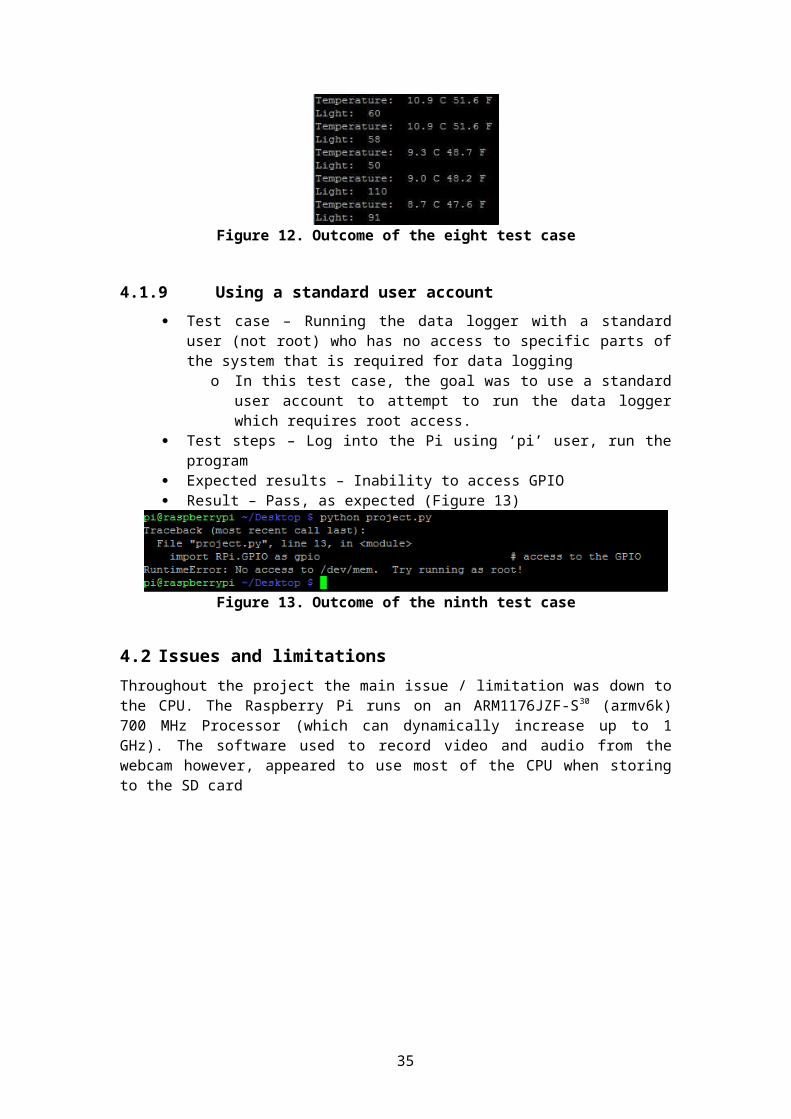
Figure 16. List of frame formats for webcam
2. Open ‘logger.py’ either remotely or locally.
3. To change the variables for the storing or streaming of webcama) Scroll down to ‘def startRecord(method):’b) Edit the appropriate variables (frameRate, frameSize, and other important
parameters)
2. To change the variables for the single image capturea) Scroll down to ‘def singleImg():’b) Edit the appropriate variables (frameSize, inputName)
3. Save the Python script and execute it.
35
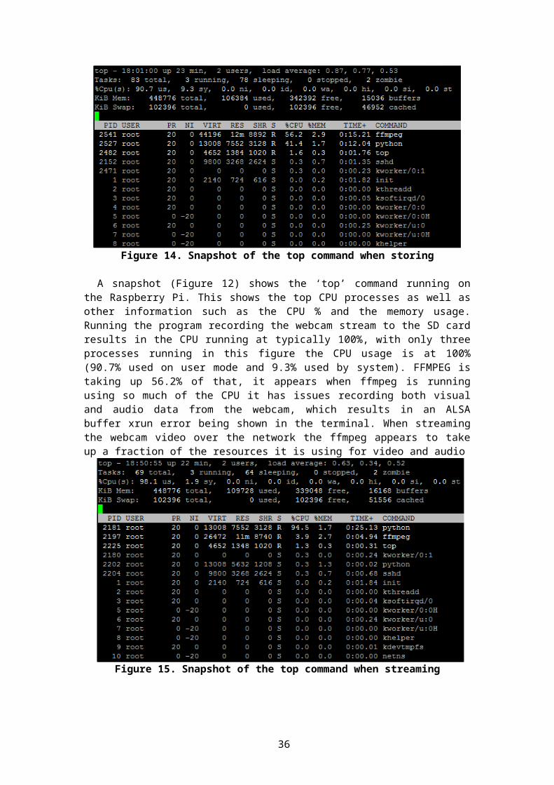
Appendix D User guide
This appendix contains the User guide which shows the end user how to run the program as well as carry out various tasks that the software will be used to do.
Auto login:
This will allow the Raspberry Pi to automatically log in using the root account without prompting for a username and password during every start up, this only works locally within the Pi, connecting via SSH will still require the user to enter a username and password.
1. Log in using any account.
2. Enter ‘sudo nano /etc/inittab’.
3. Scroll down until ‘1:2345:respawn:/sbin/getty –noclear 38400 tty1’ is visible.
4. After /sbin/getty type ‘—autologin root’.
5. It should now read ‘1:2345:respawn:/sbin/getty –autologin root –noclear 38400 tty1’.
6. Press Ctrl + X, a message should appear ‘Save modified buffer’.
7. Type ‘Y’, another message will show ‘file name to write’.
8. Press enter.
9. Restart the Raspberry Pi and it should automatically log in using ‘root’.
Setting script to auto run:
This will allow the Python script to automatically run when the user log into a user (if not using auto login) allowing the program to run with no visual display.
1. Log in using any account.
2. Enter ‘sudo nano /etc/profile’.
3. Scroll down to the bottom of the page.
4. At the end enter ‘python /home/pi/Desktop/logger.py’.
5. Press Ctrl + X, a message should appear ‘Save modified buffer’.
6. Type ‘Y’, another message will show ‘file name to write’.
7. Press enter.
8. Restart the Raspberry Pi and the script should automatically start after logging in (if not using the auto login).
36
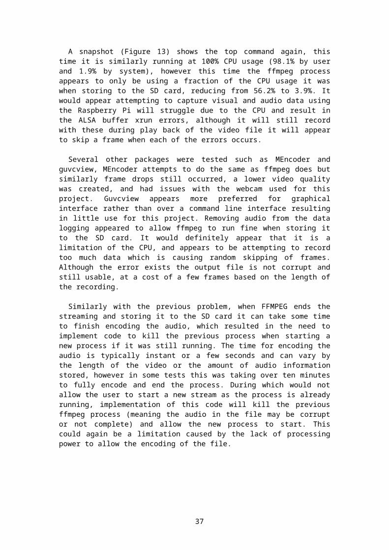
Running the script:
NOTE: When running the python script try to make sure it is only loaded once (either remotely or locally), if the user load it via SSH and again from the Pi directly it could cause issues and unexpected commands.
Using graphical session:
To use the program on the graphical desktop a small number of extra steps will be required to ensure the file can be executed
1. Log in using root user (‘root’) a. If the root password has not been set log into the default user (default user: pi
default password: raspberry).b. Enter ‘sudo passwd’ in terminal the user should receive a prompt asking for
the new password then confirmation.
Figure 17. Terminal view for changing root password
2. Run the graphical desktop using command ‘startx’.
3. Open the file manager (Menu > Accessories > File manager).
4. Locate /home/pi/Desktop.
5. Right click on the ‘logger.py’ file and go to Properties.
6. Under the Permissions tab tick the ‘Make the file executable’ box and click Ok.
7. Double click the logger.py file and execute in terminal.
8. The python script should now have loaded.
Using terminal:
1. Log in using root user (‘root’)a. If the root password has not been set, log into the default user (user: pi
password: raspberry).b. Enter ‘sudo passwd’ in terminal the user should receive a prompt asking for
the new password then confirmation.
Figure 18. Terminal view for changing root password
2. Run the command “cd /home/pi/Desktop”
37
3. Run “python logger.py”.
4. The python script should now have loaded within the terminal.
Figure 19. Terminal view when running program
Streaming webcam footage over the network:
1. Locate the middle button (indicated by S2) on the Gertboard and press it (or press 2 on a keyboard if remotely connected).
2. A message in the terminal should state that the Recording method has changed to ‘stream’.
Figure 20. Terminal view showing stream
3. Locate the left button (indicated by S3) on the Gertboard and press it (or press 1 on a keyboard if remotely connected).
4. A warning will appear followed by sensor information (temperature and optical).
Figure 21. Terminal view when beginning logging
5. The red LED will disable and the green LED will now be showing.
6. Open a media player such as VLC and load the stream http://ip-address-of-pi:8001/webcam.mjpeg
7. The sensor information is sent to COSM and can be viewed on;a. https://cosm.com/users/scottrpi# - Overviewb. https://cosm.com/feeds/117510 - Opticalc. https://cosm.com/feeds/117505 - Temperature
8. Within the ‘logger’ folder (home/pi/Desktop/logger) a file will be created/updated named ‘light.txt’ and ‘temperatures.txt’ which contain information from the sensors.
9. Press the left button again (or press 1 on keyboard) to end the sensor data logging.
10. The green LED will disable and the red LED will again be showing.
38
11. (If remotely connected) press Q to end the webcam stream.
Storing webcam footage on the SD card:
1. The default method when the script is loaded sets it to store data to the SD card (if it has been changed press 2 or middle button/S2).
Figure 22. Terminal view showing store
2. Locate the left button (indicated by S3) on the Gertboard and press it (or press 1 on a keyboard if remotely connected).
3. A warning will appear followed by sensor information (temperature and optical).
Figure 23. Terminal view when beginning logging
4. The red LED will disable and the green LED will now be showing.
5. Again the sensor information is sent to COSM and can be viewed on;a. https://cosm.com/users/scottrpi# - Overviewb. https://cosm.com/feeds/117510 - Opticalc. https://cosm.com/feeds/117505 - Temperature
6. Within the ‘logger’ folder (home/pi/Desktop/logger) a file will be created/updated named ‘light.txt’ and ‘temperatures.txt’ which will contain information from the sensors as well as a ‘webcam-XXXX-XX-XX~XX:XX:XX.mpeg’ file containing the webcam footage and the timestamp from when it was taken (in the filename).
Figure 24. List of contents within logger folder
7. Press the left button again (or press 1 on keyboard) to end the sensor data logging.
8. The green LED will disable and the red LED will again be showing.
9. (If remotely connected) press Q to end the webcam storing.
Taking a single webcam image:
1. Locate the right button (indicated by S1) on the Gertboard and press it (or press 3 on a keyboard if remotely connected).
39
2. The yellow LED will flash on for a second and off again.
3. A message in terminal should state ‘Writing JPEG image to …’.
Figure 25. Terminal view taking single image
4. Within the ‘logger’ folder (home/pi/Desktop/logger) a file will be created named ‘image-XXXX-XX-XX~XX:XX:XX.jpg’ which will contain the single image and the timestamp from when it was taken (in the filename).
40
Appendix E Source code for logger.py Program
This appendix contains the source code for the logger.py file which is the main program which allows data logging.
#**********************************************************************************************************## Name: project.py
## Description: Python program for the Data Logger
## OS: Raspbian
## Author: Scott Cairns
## Notes: If any errors occur, ensure that installation guide has been followed properly ##**********************************************************************************************************#
import os # used for terminal commandsimport time # get timestamp to put on files and gpioimport datetime # used for timestampimport RPi.GPIO as gpio # access to the GPIOimport spidev # for A/D convertersimport multiprocessing # for threading/multiprocessingimport eeml # Markup language for COSMfrom evdev import UInput, ecodes as e # Imitating a key eventimport signal # for killing taskimport termios # for key pressesimport thread # for key presses thread
# reload spi drivers prevent spi failuresimport subprocessunload_spi = subprocess.Popen('sudo rmmod spi_bcm2708', shell=True, stdout=subprocess.PIPE)start_spi = subprocess.Popen('sudo modprobe spi_bcm2708', shell=True, stdout=subprocess.PIPE)
# set up GPIO pins for 3 input (buttons) and 3 output (LEDs)gpio.setmode(gpio.BCM) # Sets to BM mode which allows you to use visual pin numbergpio.setwarnings(False) # Sometimes 'channel already in use' warning shows, this disables itredLED = 17 # variable to hold GPIO pin number for red LEDgreenLED = 22 # GPIO pin number for green LED
41
yellowLED = 18 # GPIO pin number for yellow LEDgpio.setup(yellowLED, gpio.OUT) # GPIO ID for yellow LED (single image)gpio.setup(redLED, gpio.OUT) # GPIO ID for red LED (stop recording)gpio.setup(greenLED, gpio.OUT) # GPIO ID for green LEDgpio.setup(23, gpio.IN, pull_up_down=gpio.PUD_UP) # Set up button on Gertboardgpio.setup(24, gpio.IN, pull_up_down=gpio.PUD_UP) # Set up button on Gertboardgpio.setup(25, gpio.IN, pull_up_down=gpio.PUD_UP) # Set up button on Gertboard
# set all GPIO LEDs to be disabled by default except redgpio.output(yellowLED, False)gpio.output(redLED, True) # True to show it's not recordinggpio.output(greenLED, False)
# boolean to hold value if recording or notrecording = False
# variable to hold the recording method (store or stream)method = "store"
# variable to hold the current detected key presskeyDetect = ''
# variable to hold whether we're looking for key presses or not # (prevent it being called thousands of times)keyRun = False
# Variables for using in console warning using ANSI escaped sequencesgreen = '\033[92m' # colour code for greenblue = '\033[94m' # colour code for blueyellow = '\033[93m' # colour code for yellowred = '\033[91m' # colour code for redendc = '\033[0m' # end of console warning
# variable to hold the connection method (if remotely connected linux sets the 'DISPLAY'# environment variable (such as localhost:10.0) if not then returns Empty variable ('None')conVar = os.environ.get('DISPLAY')if (conVar != None): # if connection method isn't 'None' ie remotely connected
conMethod = "remote" # set the method to 'remote'print yellow + 'INFO: As you are remotely connected you can overwrite buttons' +
endc # print infoprint yellow + 'Key 1 = GPIO #23 (Record), Key 2 = GPIO #24 (Stop record), Key 3
= GPIO #25 (Capture)' + endc # print infoelse: # if it's not remotely connected
conMethod = "local" # set method to 'local'
# COSM info - allows real time graphing over the internettemp_api_key = 'R-TZoaYnOUWVnf-s_mLMHwL3LQeSAKxZY0tNdThiS0I2VT0g'
# API key for COSM - Temptemp_api_feed = 117505
# Feed ID for COSM - Templight_api_key = '_Ea8XluPFqxAv3IQF-Zhk_3VqBySAKwrZGxXT0hPQTREOD0g'
# API key for COSM - Light
42
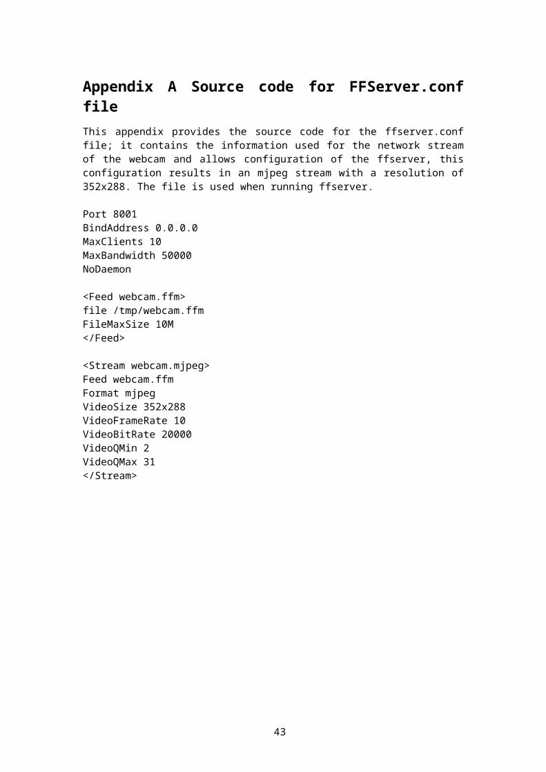
light_api_feed = 117510# Feed ID for COSM - Light
temp_api_url = '/v2/feeds/{feednum}.xml'.format(feednum = temp_api_feed)# API URL
light_api_url = '/v2/feeds/{feednum}.xml'.format(feednum = light_api_feed)# API URL
# https://cosm.com/users/scottrpi - shows both feeds# https://cosm.com/feeds/117510 - shows feed for light sensor# https://cosm.com/feeds/117505 - shows feed for temp sensor
# Function to obtain the Analog to Digital conversion and return the valuedef get_adc(channel):
spi = spidev.SpiDev() # use spidev python wrapper to communicate with SPI port
spi.open(0,0) # open channel 0 (ADC is on SPI channel 0 (CE0 / GPIO8)
#r = spi.xfer2([1,(3)<<4,0])#adc_val = ((r[1]&3) << 8) + r[2]if (channel == 0): #
Channel 0 (actual AC1) is the Light sensor# Send start bit, sgl/diff, odd/sign, MSBF
# channel = 0 sends 0000 0001 1000 0000 0000 0000 # channel = 1 sends 0000 0001 1100 0000 0000 0000 # sgl/diff = 1; odd/sign = channel; MSBF = 0
r = spi.xfer2([1,(2+channel)<<6,0])# spi.xfer2 returns same number of 8 bit bytes
# as sent. In this case, 3 - 8 bit bytes are returned # We must then parse out the correct 10 bit byte from # the 24 bits returned. The following line discards # all bits but the 10 data bits from the center of # the last 2 bytes: XXXX XXXX - XXXX DDDD - DDDD DDXX
adc_val = ((r[1]&31) << 6) + (r[2] >> 2)if (channel == 1): #
Channel 1 (Actual AC0) is the Temp sensor# Send start bit, sgl/diff, odd/sign, MSBF
# channel = 0 sends 0000 0001 1000 0000 0000 0000 # channel = 1 sends 0000 0001 1100 0000 0000 0000 # sgl/diff = 1; odd/sign = channel; MSBF = 0
r = spi.xfer2([1,(2+channel)<<6,0])# spi.xfer2 returns same number of 8 bit bytes
# as sent. In this case, 3 - 8 bit bytes are returned # We must then parse out the correct 10 bit byte from # the 24 bits returned. The following line discards # all bits but the 10 data bits from the center of # the last 2 bytes: XXXX XXXX - XXXX DDDD - DDDD DDXX
adc_val = ((r[1]&31) << 6) + (r[2] >> 2)return adc_val
# Function to request the digital value from temperature sensor and record it and graph itdef recordTemp():
try:while 1: # Loop
timeInt = time.time()# Get current timestamp as an integer
43
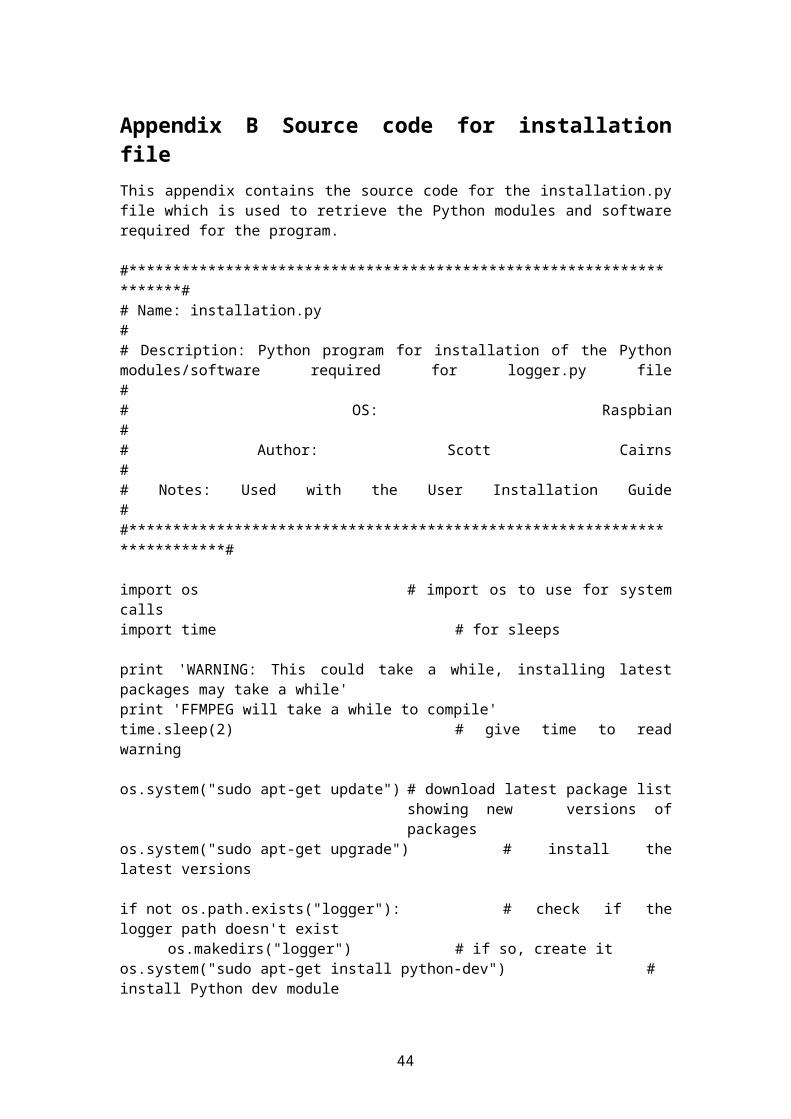
timeStr = datetime.datetime.fromtimestamp(timeInt).strftime('%Y-%m-%d %H:%M:%S') # Convert it to a string
reading = get_adc(1) # get temp sensor digital reading
c_temp = (((reading * (3300.0 / 1024.0)) - 100.0) / 10.0) - 40.0 # Calculate temp in C
f_temp = ( c_temp * 9.0 / 5.0) + 32 # Calculate temp in F
c_temp = "%.1f" % c_temp# set C temp to 1 decimal place
f_temp = "%.1f" % f_temp# set F temp to 1 decimal place
print "Temperature: ", c_temp, "C", f_temp, "F" # print the temperatures into terminal
f = open('/home/pi/Desktop/logger/temperatures.txt', 'a') # Opens file 'temperatures' with method A for append
f.write("Time: " + timeStr + " Temperature: " + c_temp + "C " + f_temp + "F\n") # write temp to file
f.close() # close file once finished the write
#pac = eeml.Pachube(temp_api_url, temp_api_key)# using markup language to connect to COSM (previously Pachube)
#pac.update([eeml.Data(0, c_temp, unit=eeml.Celsius())])# set the data and use Celsius unit
#pac.put()# do it
time.sleep(30) # Only record the temperatures every 30 seconds
return;except KeyboardInterrupt: # Ctrl C on keyboard
os.system("reset") # Reset terminal to prevent hidden characters after program ends
gpio.cleanup() # reset GPIO ports if KeyboardInterrupt
# Function to request the digital value from light sensor and record it and graph itdef recordLight():
try:while 1: # Loop
timeInt = time.time() # Get current timestamp as an integer
timeStr = datetime.datetime.fromtimestamp(timeInt).strftime('%Y-%m-%d %H:%M:%S') # Convert it to a string
reading = get_adc(0) # get light sensor digital reading
print "Light: ", reading # print light sensor readinglight = reading # set light to
the return variablelight = "%.1f" % light # set light reading to
1 decimal placef = open('/home/pi/Desktop/logger/light.txt', 'a')
# Opens file 'light.txt' with method a for appendf.write("Time: " + timeStr + " Light: " + light + "\n") # write light
info to filef.close()
# Close file once finished writing
44
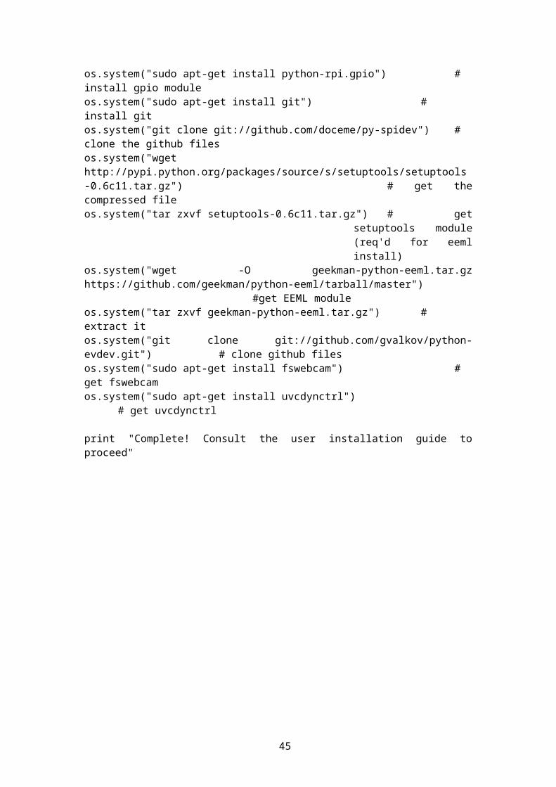
#pac = eeml.Pachube(light_api_url, light_api_key) # using markup language to connect to COSM (previously Pachube)
#pac.update([eeml.Data(0, light)])# run update, don't set a data type as it's just raw number
#pac.put()# do it
time.sleep(30) # Record light every 30 seconds
return;except KeyboardInterrupt: # Ctrl C on keyboard
os.system("reset") # Reset terminal to prevent hidden characters after program ends
gpio.cleanup() # reset GPIO ports if KeyboardInterrupt
# Function to set variables required for recording and start the recordingdef startRecord(method):
try:# set up the variables required for the recordingserverConf = "/etc/ffserver.conf" # path to the ffserver configlogLevel = "error" # logging level, quiet, panic,
fatal, error, warning, info, verbose, debugrframeRate = "1" # Frame rate in Hz
(for saving/recording)sframeRate = "30" # Frame rate in Hz
(for streaming)frameSize = "352x288" # Set frame size in width x
height (640x480, 352x288, 320x240, 176x144, 160x120 supported)fileFormat = "video4linux2" # output formatinputName = "/dev/video0" # Input type, video0 for
cameraoutLocation = "http://localhost:8001/webcam.ffm" # Output location,
over networktimeInt = time.time() # Get current timestamp as
an integertimeStr = datetime.datetime.fromtimestamp(timeInt).strftime('%Y-%m-%d~
%H:%M:%S') # Convert it to a stringoutLocationSave = "/home/pi/Desktop/logger/webcam-%s.avi" %timeStr # Output location, in this case save under /home/pi/ with name 'webcam-
timestamp.mpg'vSync = "1" # video
sync (make sure no duplicate frames etcaSync = "1" # audio
sync to fix wait at startaFormat = "alsa" # format for audio:
oss or alsaaChannel = "1" # audio channelsaInput = "hw:1,0" # input device for
audio (sound card #1 sub #0)
# Run terminal command to run ffserver and ffmpeg#os.system("ffserver -f " + serverConf + " & ffmpeg -v " + logLevel + # " -r " + frameRate + " -s " + frameSize + " -f " + fileFormat +# " -i " + inputName + " -vcodec mjpeg -f alsa -ac 1 -ar 48000
-i hw:1,0 " + outLocation + " " + outLocationSave)
45
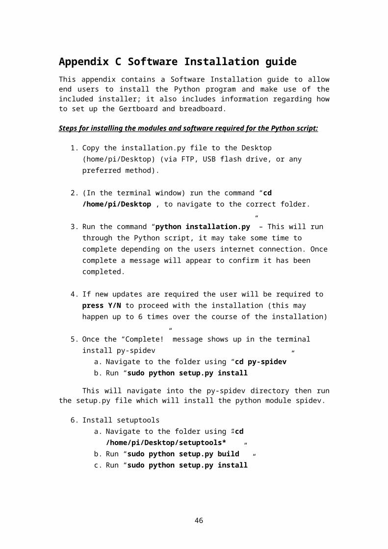
p = subprocess.Popen(['ps', '-A'], stdout=subprocess.PIPE) # check open processes
out, err = p.communicate()# record them in 'out'
for line in out.splitlines():# check each lineif 'ffmpeg' in line:
# if ffmpeg is in itprint red + "Attempting to kill ffmpeg - May cause audio
issues with last save" + endctime.sleep(2)
# show warning for 2 seconds before continuingpid = int(line.split(None, 1)[0])
# get the process IDos.kill(pid, signal.SIGKILL)
# send kill signal
if (method == "store"): # if the selected method is to store it to the SD card (video + audio)
# print "Recording has started - Storing to SD card" # print appropriate message
# os.system("ffmpeg -v " + logLevel + " -r " + frameRate + " -s " + frameSize + " -f " + fileFormat +
# " -i " + inputName + " -f alsa -ac 1 -i hw:1,0 " + " " + outLocationSave)
os.system("ffmpeg -v " + logLevel + " -r " + rframeRate + " -s " + frameSize + " -f " + fileFormat +
" -vsync " + vSync + " -i " + inputName + " -f " + aFormat + " -ar 8000 -ac " + aChannel + " -async " +
aSync + " -i " + aInput + " " + outLocationSave)elif (method == "stream"): # if the selected method is to strream it over
network (video only)print "Recording has started - Streaming across network"# print
appropriate messageos.system("ffserver -f " + serverConf + " & ffmpeg -v " + logLevel +
" -r " + sframeRate + " -s " + frameSize + " -f " + fileFormat +
" -i " + inputName + " " + outLocation)
return;except KeyboardInterrupt: # Ctrl C on keyboard
os.system("reset") # Reset terminal to prevent hidden characters after program ends
gpio.cleanup() # reset GPIO ports if KeyboardInterrupt
# Function to end the processes / recordingdef stopRecord(recording):
try:if (recording == True): # if recording has
startedif (p1.is_alive()): # If process
1 (recordTemp) is alive
46
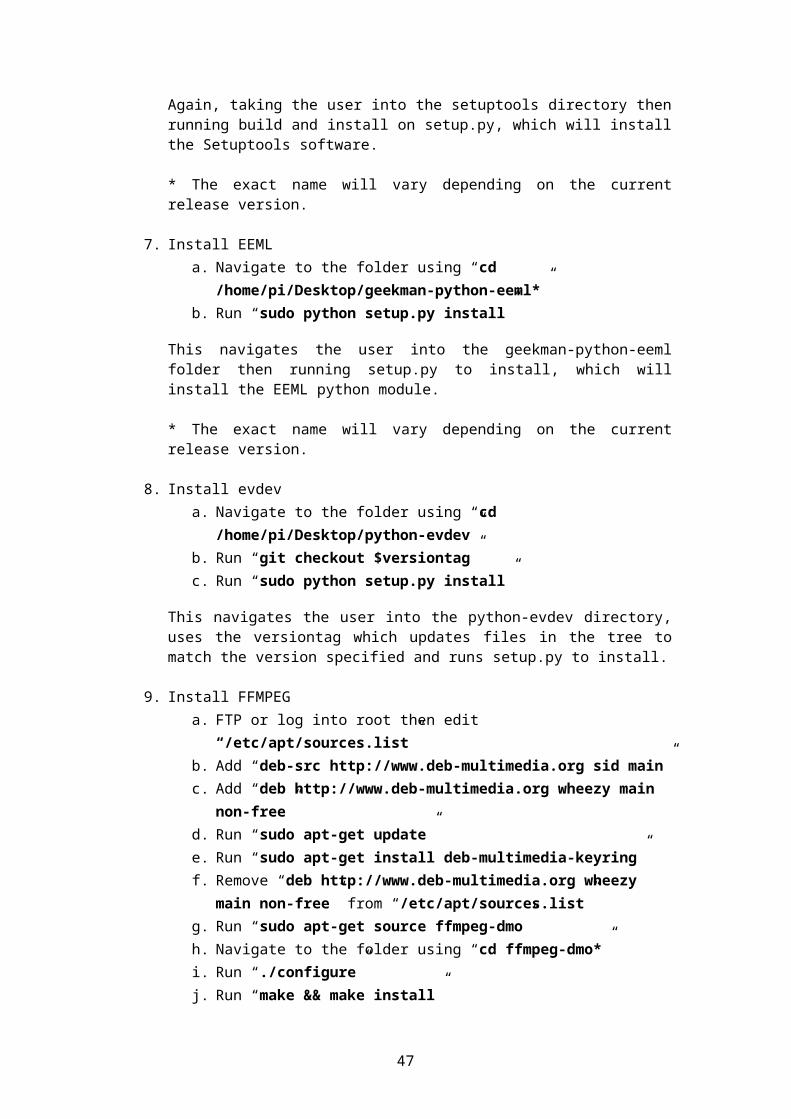
p1.terminate() # terminate process
if (p2.is_alive()): # If process 2 (recordLight) is alive
p2.terminate() # terminate process
if (p3.is_alive()): # If process 3 (startRecord) is alive
p3.terminate() # terminate process
# Imitate a key press, only works if running script from device (remote connection requires pressing q)
if (conMethod == "local"): # only do it if actually on the device
ui = UInput() # create new uinput
ui.write(e.EV_KEY,e.KEY_Q, 1) # key Q press down
ui.write(e.EV_KEY,e.KEY_Q, 0) # key Q press up
ui.syn() # do it
ui.close()# close uinput
print "Recorded finished" # print appropriate message
else: # if recording hasn't started
print "Recording has not yet started" # print appropriate messagereturn;
except KeyboardInterrupt: # Ctrl C on keyboardos.system("reset") # Reset terminal to prevent hidden characters
after program endsgpio.cleanup() # reset GPIO ports if KeyboardInterrupt
# Function to set variables for an image and execute itdef singleImg():
frameSize = "352x288" # Set frame size in width x heightinputName = "/dev/video0" # Input type, video0 for cameratimeInt = time.time() # Get current timestamp as an
integertimeStr = datetime.datetime.fromtimestamp(timeInt).strftime('%Y-%m-%d~%H:
%M:%S') # Convert it to a stringpicOut = "/home/pi/Desktop/logger/image-%s.jpg" % timeStr # Output location
for single image timestamp attached
p = subprocess.Popen(['ps', '-A'], stdout=subprocess.PIPE) # check open processes
out, err = p.communicate()# record them in 'out'
47
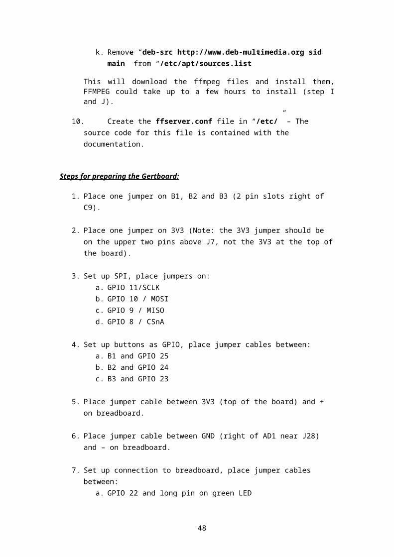
for line in out.splitlines():# check each lineif 'ffmpeg' in line:
# if ffmpeg is in itprint red + "Attempting to kill ffmpeg - May cause audio issues with
last save" + endctime.sleep(2)pid = int(line.split(None, 1)[0])
# get the process IDos.kill(pid, signal.SIGKILL)
# send kill signal
# Run terminal command which will take a single image and save it to picOutos.system("fswebcam -r " + frameSize + " -d " + inputName + " " + picOut)return;
def keyPress():try:
term = open("/dev/tty", "r") # /dev/tty is the terminal for the current process, open in reading mode
fd = term.fileno() # returns integer file desciptor
old = termios.tcgetattr(fd) # return list containing tty attributes for file descriptor
new = termios.tcgetattr(fd) # return list containing tty attributes for file descriptor
new[3] &= ~termios.ICANON & ~termios.ECHO # canonical mode and echo input characters
termios.tcsetattr(fd, termios.TCSANOW, new) # sets the parameters associated with terminal, TCSANOW = immediately
key = None # current key isn't set
try: # trykey = os.read(fd, 1) # read key press
finally: # always execute this before leaving try statement
termios.tcsetattr(fd, termios.TCSAFLUSH, old) # set attrs again this time after all output is written to object has fd has been trasmitted
term.close() # close the file
global keyDetect # allow overwriting of variable outside function
global keyRun # allow overwriting of variable outside function
if key == '1': # if key pressed is '1'
keyDetect = '1' # then set it to 1
elif key == '2': # if key is '2'keyDetect = '2' # set to 2
elif key == '3': # if key is '3'keyDetect = '3' # set to 3
elif key == 'Q': # if key is 'Q'print 'Please try again' # print message to try again
48
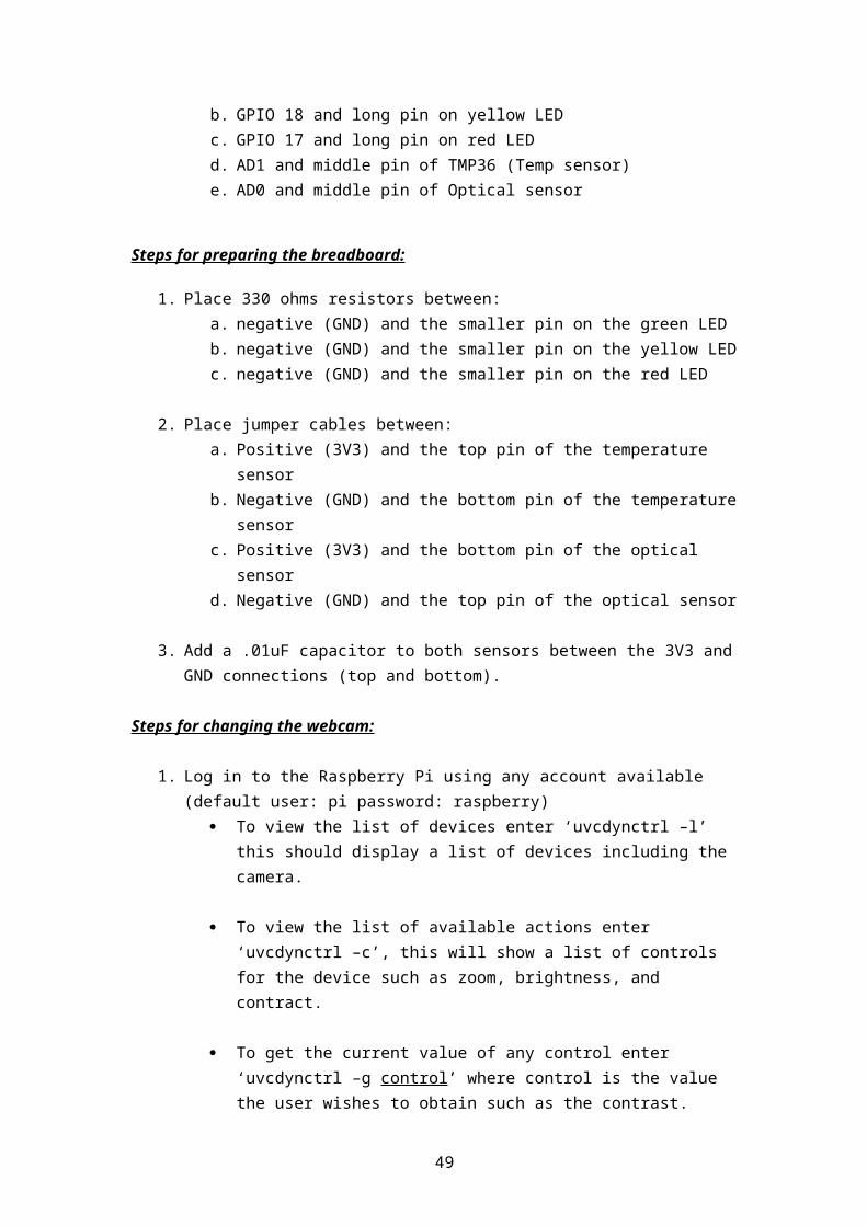
else: # otherwise
print 'Unusable key detected' # print to show unusuable key
keyRun = False # set it to false as it's not longer running
except KeyboardInterrupt: # Ctrl C on keyboardos.system("reset") # Reset terminal to prevent hidden characters
after program endsgpio.cleanup() # reset GPIO ports if KeyboardInterrupt
try:time.sleep(1) # prevent
some misreading buttons during start upprint "Python Program loaded, press a button to continue"while 1: # Infinite loop
if (((gpio.input(23) == False) or (keyDetect == '1')) and (recording == False)): # if record button is pressed and not recording, record
if (conMethod == "remote"): # give warning if remotely connected
print yellow + "INFO: As remotely connected you must press Q to end the webcam stream" + endc
print yellow + "WARNING: When ending the stream, it may take a few minutes depending on the length of recording" + endc
time.sleep(2) # give time to read the info
gpio.output(redLED, False) # disable the red LED
gpio.output(greenLED, True) # enable the LED to show it's recording (green)
recording = True # Set recording variable to true
p1 = multiprocessing.Process(target=recordTemp) # create a process with target as recordTemp
p2 = multiprocessing.Process(target=recordLight) # create a process with target as recordLight
p3 = multiprocessing.Process(target=startRecord, args=(method,))# create a process with target as startRecord taking 'method' variable as param
p3.start() # Start process to startRecord
time.sleep(2) # wait a few seconds
p1.start() # Start process to recordTemp
time.sleep(3) # wait a few seconds
p2.start() # Start process to recordLight
keyDetect = '' # Reset keyDetect
49

time.sleep(1) # prevent button from being detected several times with 1 press
if (((gpio.input(23) == False) or (keyDetect == '1')) and (recording == True)):# if record button is pressed and recording, stop
gpio.output(greenLED, False) # disable the LED to show it's recording (green)
gpio.output(redLED, True) # enable the LED to show it's not recording (red)
stopRecord(recording); # Call the stopRecord function (pass recording boolean)
recording = False # Set recording variable to false
keyDetect = '' # reset keyDetect
time.sleep(1) # prevent button from being detected several times with 1 press
if (((gpio.input(24) == False) or (keyDetect == '2')) and (method == "store")): # if switch button is pressed and current method is store
method = "stream" # change method to stream
print "Recording method has changed to stream - The recording will be streamed across the network" # print appropriate message
keyDetect = '' # reset keyDetect
time.sleep(1) # sleep for 1 second
if (((gpio.input(24) == False) or (keyDetect == '2')) and (method == "stream")): # if switch button is pressed and current method is stream
method = "store" # change method to store
print "Recording method has changed to store - The recording will be saved to the SD card" # print appropriate message
keyDetect = '' # reset keyDetect
time.sleep(1) # sleep for 1 second
if ((gpio.input(25) == False) or (keyDetect == '3')):gpio.output(yellowLED, True) # enable LED for short
duration to show it's taken image (yellow)time.sleep(1) # sleep for
one secondgpio.output(yellowLED, False) # disable LED againsingleImg(); # Call the
singleImg functionkeyDetect = '' # reset
keyDetecttime.sleep(1) # prevent
button from being detected several times with 1 pressif ((conMethod == "remote") and (keyRun == False)):
# if remotely connected start function to allow key detectiontime.sleep(1) # allow time
for q to be pressedthread.start_new_thread( keyPress, ())keyRun = True # set it to
true so it won't call this statement each loop
50
except KeyboardInterrupt: # Ctrl C on keyboardos.system("reset") # Reset terminal to prevent hidden characters after
program endsgpio.cleanup() # reset GPIO ports if KeyboardInterrupt
gpio.cleanup() # reset GPIO ports if exitos.system("reset") # Reset terminal to prevent hidden characters after program ends
51