cables and cable systems for photovoltaic · pdf file2 welcome to helukabel®...
TRANSCRIPT
www.helukabel.de
Cables and cable systems for photovoltaic installations
2
Welcome to HELUKABEL®
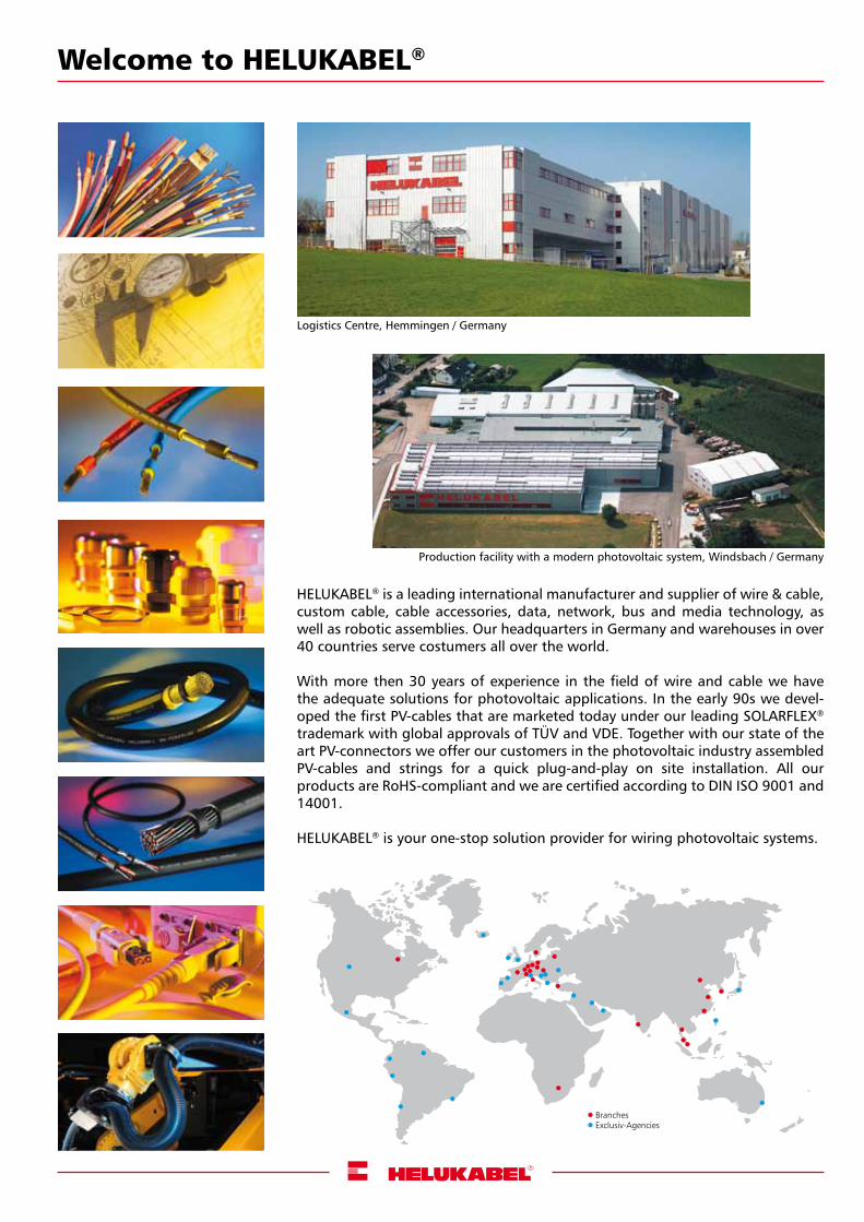
HELUKABEL® is a leading international manufacturer and supplier of wire & cable, custom cable, cable accessories, data, network, bus and media technology, as well as robotic assemblies. Our headquarters in Germany and warehouses in over 40 countries serve costumers all over the world.
With more then 30 years of experience in the field of wire and cable we have the adequate solutions for photovoltaic applications. In the early 90s we devel-oped the first PV-cables that are marketed today under our leading SOLARFLEX® trademark with global approvals of TÜV and VDE. Together with our state of the art PV-connectors we offer our customers in the photovoltaic industry assembledPV-cables and strings for a quick plug-and-play on site installation. All our products are RoHS-compliant and we are certified according to DIN ISO 9001 and 14001.
HELUKABEL® is your one-stop solution provider for wiring photovoltaic systems.
Logistics Centre, Hemmingen / Germany
Production facility with a modern photovoltaic system, Windsbach / Germany
Branches Exclusiv-Agencies
3
Contents
Reference cabling ...................................................................................................................................................
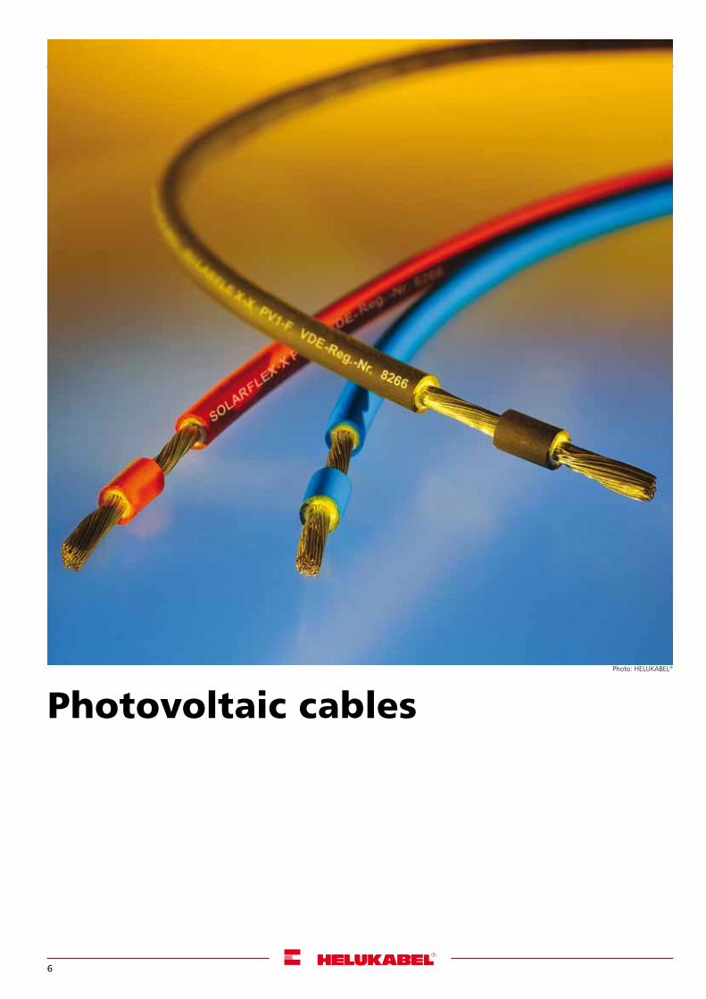
Photovoltaic cables
SOLARFLEX®-X PV1-F .................................................................................................................................................
SOLARFLEX®-X PV1-F TWIN .......................................................................................................................................
Pre-assembled solutions
Chains...............................................................................................................................................................
PV wiring fuse/diode, pre-assembled potential equalization cable ..........................................................................
Adapters..................................................................................................................................................................
Photovoltaic cables...........................................................................................................................................
Components
Panel boxes..............................................................................................................................................................
Male and female connectors............................................................................................................................
Branches...........................................................................................................................................................
Cable Accessories
Cable glands............................................................................................................................................................
Miscellaneous...................................................................................................................................................
Tools
Cables & wires
PVC control cables............................................................................................................................................
Allweather and rubber cables...........................................................................................................................
Power cables.....................................................................................................................................................
Installation cables....................................................................................................................................................
Medium voltage cables.....................................................................................................................................
Notes..........................................................................................................................................................................
Achieving success through quality and innovation.....................................................................................................
HELUKABEL® – global network ...................................................................................................................................
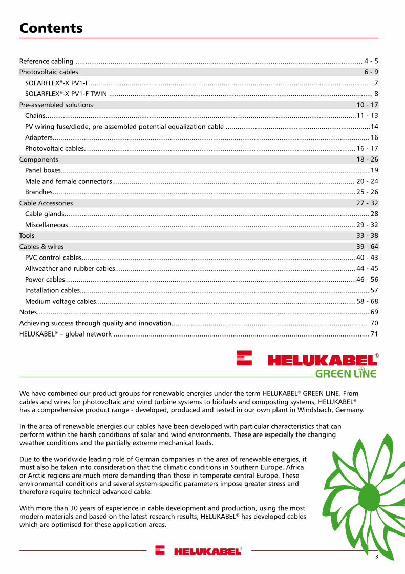
We have combined our product groups for renewable energies under the term HELUKABEL® GREEN LINE. From cables and wires for photovoltaic and wind turbine systems to biofuels and composting systems, HELUKABEL® has a comprehensive product range - developed, produced and tested in our own plant in Windsbach, Germany.
In the area of renewable energies our cables have been developed with particular characteristics that can perform within the harsh conditions of solar and wind environments. These are especially the changing weather conditions and the partially extreme mechanical loads.
Due to the worldwide leading role of German companies in the area of renewable energies, it must also be taken into consideration that the climatic conditions in Southern Europe, Africa or Arctic regions are much more demanding than those in temperate central Europe. These environmental conditions and several system-specific parameters impose greater stress and therefore require technical advanced cable.
With more than 30 years of experience in cable development and production, using the most modern materials and based on the latest research results, HELUKABEL® has developed cables which are optimised for these application areas.
GREEN LINE
4 - 5
6 - 9
7
8
10 - 17
11 - 13
14
16
16 - 17
18 - 26
19
20 - 24
25 - 26
27 - 32
28
29 - 32
33 - 38
39 - 64
40 - 43
44 - 45
46 - 56
57
58 - 68
69
70
71
4
#
=
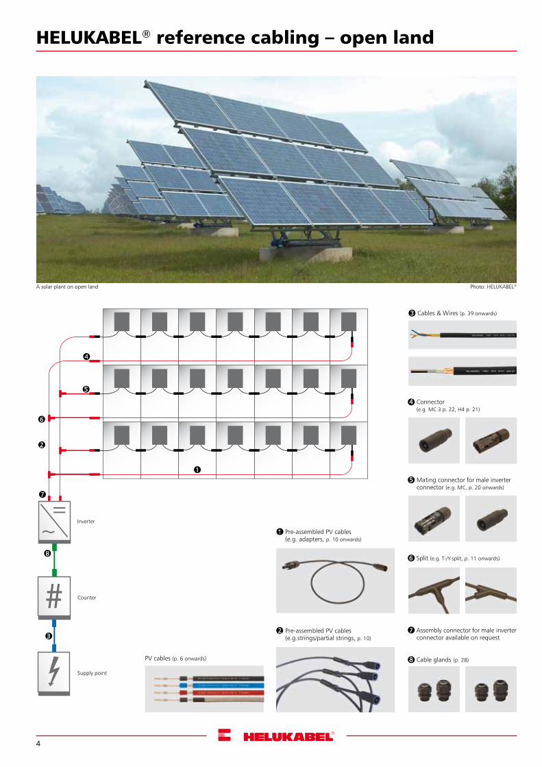
HELUKABEL® reference cabling – open land
Inverter
Counter
Supply point
A solar plant on open land
5 Mating connector for male inverter connector (e.g. MC, p. 20 onwards)
4 Connector (e.g. MC 3 p. 22, H4 p. 21)
3 Cables & Wires (p. 39 onwards)
6 Split (e.g. T-/Y-split, p. 11 onwards)
7 Assembly connector for male inverter connector available on request
8 Cable glands (p. 28)
2 Pre-assembled PV cables (e.g.strings/partial strings, p. 10)
5
7
2
4
8
6
3
1
Photo: HELUKABEL®
PV cables (p. 6 onwards)
1 Pre-assembled PV cables (e.g. adapters, p. 10 onwards)
5
#
== =
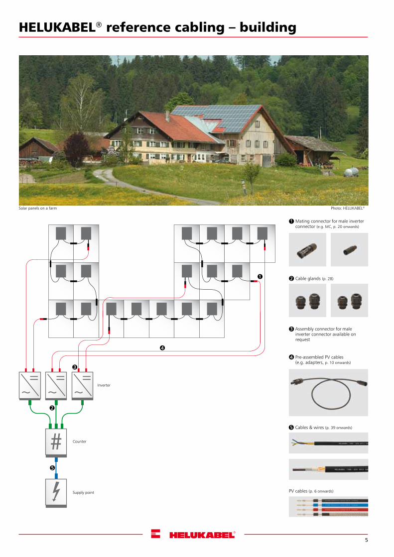
HELUKABEL® reference cabling – building
3 Assembly connector for male inverter connector available on request
Inverter
Counter
Supply point
Solar panels on a farm
1
2
4
3
5
Photo: HELUKABEL®
4 Pre-assembled PV cables (e.g. adapters, p. 10 onwards)
5 Cables & wires (p. 39 onwards)
1 Mating connector for male inverter connector (e.g. MC, p. 20 onwards)
2 Cable glands (p. 28)
PV cables (p. 6 onwards)
6
Photovoltaic cables Photo: HELUKABEL®
7
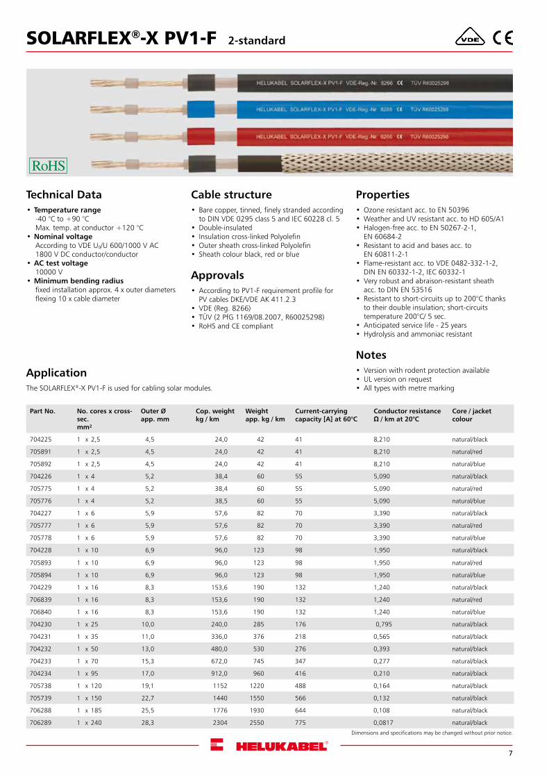
Technical Data•Temperature range
-40 °C to +90 °CMax. temp. at conductor +120 °C
•Nominal voltageAccording to VDE U0/U 600/1000 V AC1800 V DC conductor/conductor
•AC test voltage 10000 V
•Minimum bending radiusfixed installation approx. 4 x outer diametersflexing 10 x cable diameter
Cable structure• Bare copper, tinned, finely stranded according
to DIN VDE 0295 class 5 and IEC 60228 cl. 5 •Double-insulated• Insulation cross-linked Polyolefin•Outer sheath cross-linked Polyolefin• Sheath colour black, red or blue
Approvals•According to PV1-F requirement profile for
PV cables DKE/VDE AK 411.2.3• VDE (Reg. 8266)• TÜV (2 PfG 1169/08.2007, R60025298)• RoHS and CE compliant
Properties•Ozone resistant acc. to EN 50396•Weather and UV resistant acc. to HD 605/A1•Halogen-free acc. to EN 50267-2-1,
EN 60684-2• Resistant to acid and bases acc. to
EN 60811-2-1• Flame-resistant acc. to VDE 0482-332-1-2,
DIN EN 60332-1-2, IEC 60332-1• Very robust and abraison-resistant sheath
acc. to DIN EN 53516• Resistant to short-circuits up to 200°C thanks
to their double insulation; short-circuits temperature 200°C/ 5 sec.
•Anticipated service life - 25 years•Hydrolysis and ammoniac resistant
Notes• Version with rodent protection available•UL version on request•All types with metre marking
ApplicationThe SOLARFLEX®-X PV1-F is used for cabling solar modules.
Dimensions and specifications may be changed without prior notice.
SOLARFLEX®-X PV1-F 2-standard
Part No. No. cores x cross-sec.mm²
Outer Øapp. mm
Cop. weight kg / km
Weightapp. kg / km
Current-carrying capacity [A] at 60°C
Conductor resistance Ω/kmat20°C
Core / jacket colour
704225 1 x 2,5 4,5 24,0 42 41 8,210 natural/black
705891 1 x 2,5 4,5 24,0 42 41 8,210 natural/red
705892 1 x 2,5 4,5 24,0 42 41 8,210 natural/blue
704226 1 x 4 5,2 38,4 60 55 5,090 natural/black
705775 1 x 4 5,2 38,4 60 55 5,090 natural/red
705776 1 x 4 5,2 38,5 60 55 5,090 natural/blue
704227 1 x 6 5,9 57,6 82 70 3,390 natural/black
705777 1 x 6 5,9 57,6 82 70 3,390 natural/red
705778 1 x 6 5,9 57,6 82 70 3,390 natural/blue
704228 1 x 10 6,9 96,0 123 98 1,950 natural/black
705893 1 x 10 6,9 96,0 123 98 1,950 natural/red
705894 1 x 10 6,9 96,0 123 98 1,950 natural/blue
704229 1 x 16 8,3 153,6 190 132 1,240 natural/black
706839 1 x 16 8,3 153,6 190 132 1,240 natural/red
706840 1 x 16 8,3 153,6 190 132 1,240 natural/blue
704230 1 x 25 10,0 240,0 285 176 0,795 natural/black
704231 1 x 35 11,0 336,0 376 218 0,565 natural/black
704232 1 x 50 13,0 480,0 530 276 0,393 natural/black
704233 1 x 70 15,3 672,0 745 347 0,277 natural/black
704234 1 x 95 17,0 912,0 960 416 0,210 natural/black
705738 1 x 120 19,1 1152 1220 488 0,164 natural/black
705739 1 x 150 22,7 1440 1550 566 0,132 natural/black
706288 1 x 185 25,5 1776 1930 644 0,108 natural/black
706289 1 x 240 28,3 2304 2550 775 0,0817 natural/black
8
Technical Data•Temperature range
-40 °C to +90 °CMax. temp. at conductor +120 °C
•Nominal voltageAccording to VDE U0/U 600/1000 V AC1800 V DC conductor/conductor
•AC test voltage 6500 V, 50 Hz
•Minimum bending radiusSingle 1.5 cable diametersMultiple 10 cable diameters
Cable structure• Bare copper, Class 5, tinned, finely stranded
according to DIN VDE 0295 class 5 and IEC 60228 cl. 5
•Double-insulated • Insulation cross-linked special Polyolefin •Outer sheath cross-linked special Polyolefin • Sheath colour: black
Properties•Approval: TÜV 2Pfg1169/08.2007•UV, ozone-resistant, weather-resistant,•Halogen-free•Abrasion and cut resistant• Relatively flexible• Easy to strip• Flame-resistant according to VDE 0482 Part
332-1-2, IEC 60332-1-2• Resistant to short circuits up to 200 °C thanks
to double insulation, short circuit temperature 200 °C/5 sec.
•Anticipated service life 25 years
Dimensions and specifications may be changed without prior notice.
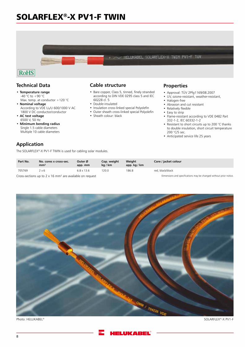
ApplicationThe SOLARFLEX®-X PV1-F TWIN is used for cabling solar modules.
Cross-sections up to 2 x 16 mm² are available on request
Part No. No. cores x cross-sec.mm²
Outer Øapp. mm
Cop. weight kg / km
Weightapp. kg / km
Core / jacket colour
705769 2 x 6 6.8 x 13.6 120.0 186.8 red, black/black
SOLARFLEX®-X PV1-F TWIN
Photo: HELUKABEL® SOLARFLEX®-X PV1-F
9
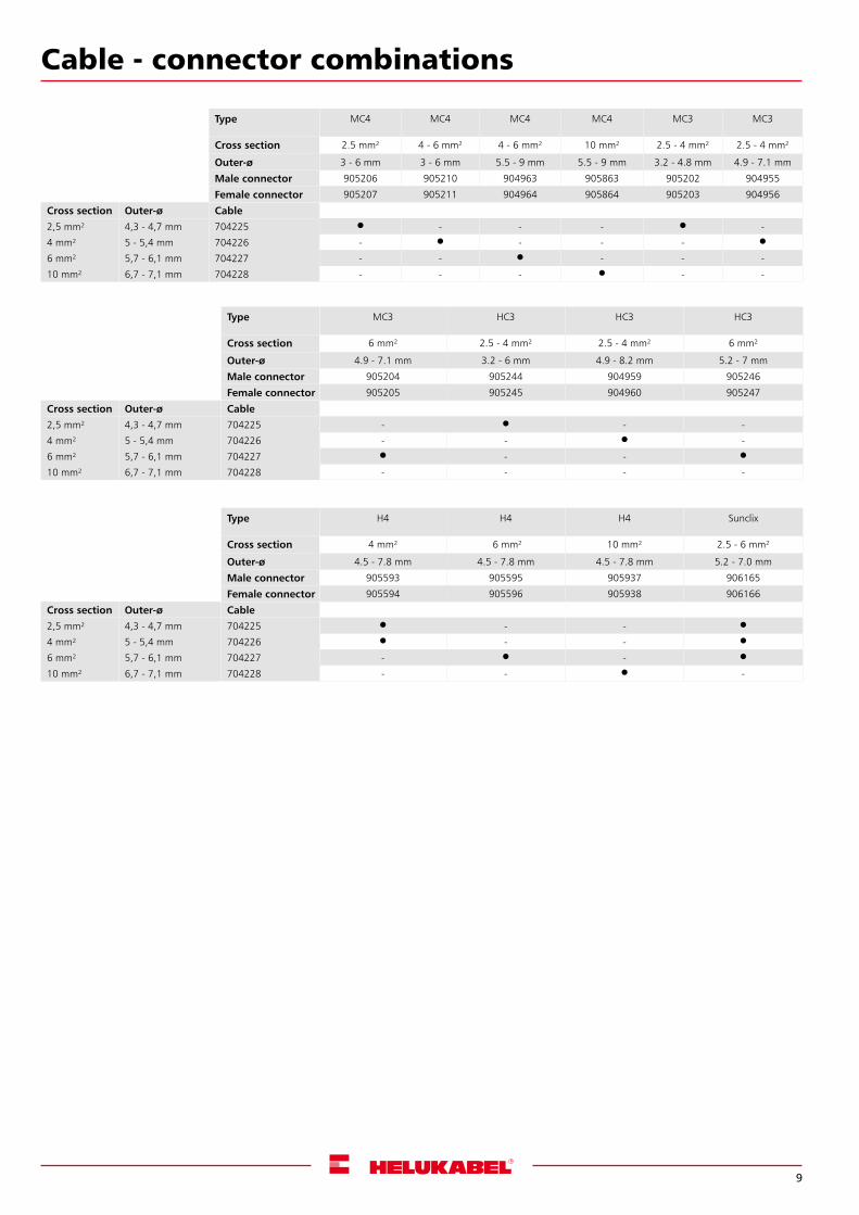
Cable - connector combinations
Type MC4 MC4 MC4 MC4 MC3 MC3
Cross section 2.5 mm² 4 - 6 mm² 4 - 6 mm² 10 mm² 2.5 - 4 mm² 2.5 - 4 mm²
Outer-ø 3 - 6 mm 3 - 6 mm 5.5 - 9 mm 5.5 - 9 mm 3.2 - 4.8 mm 4.9 - 7.1 mm
Male connector 905206 905210 904963 905863 905202 904955
Female connector 905207 905211 904964 905864 905203 904956
Cross section Outer-ø Cable
2,5 mm² 4,3 - 4,7 mm 704225 - - - -
4 mm² 5 - 5,4 mm 704226 - - - -
6 mm² 5,7 - 6,1 mm 704227 - - - - -
10 mm² 6,7 - 7,1 mm 704228 - - - - -
Type MC3 HC3 HC3 HC3
Cross section 6 mm² 2.5 - 4 mm² 2.5 - 4 mm² 6 mm²
Outer-ø 4.9 - 7.1 mm 3.2 - 6 mm 4.9 - 8.2 mm 5.2 - 7 mm
Male connector 905204 905244 904959 905246
Female connector 905205 905245 904960 905247
Cross section Outer-ø Cable
2,5 mm² 4,3 - 4,7 mm 704225 - - -
4 mm² 5 - 5,4 mm 704226 - - -
6 mm² 5,7 - 6,1 mm 704227 - -
10 mm² 6,7 - 7,1 mm 704228 - - - -
Type H4 H4 H4 Sunclix
Cross section 4 mm² 6 mm² 10 mm² 2.5 - 6 mm²
Outer-ø 4.5 - 7.8 mm 4.5 - 7.8 mm 4.5 - 7.8 mm 5.2 - 7.0 mm
Male connector 905593 905595 905937 906165
Female connector 905594 905596 905938 906166
Cross section Outer-ø Cable
2,5 mm² 4,3 - 4,7 mm 704225 - -
4 mm² 5 - 5,4 mm 704226 - -
6 mm² 5,7 - 6,1 mm 704227 - -
10 mm² 6,7 - 7,1 mm 704228 - - -
10
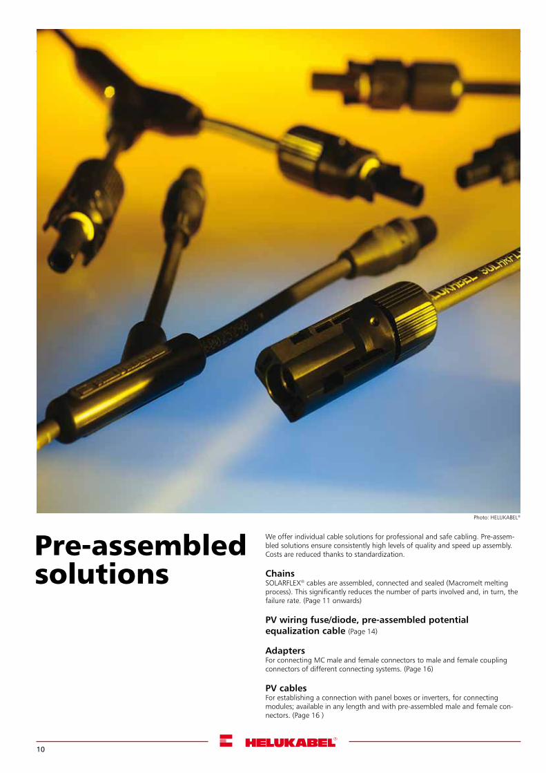
We offer individual cable solutions for professional and safe cabling. Pre-assem-bled solutions ensure consistently high levels of quality and speed up assembly. Costs are reduced thanks to standardization.
ChainsSOLARFLEX® cables are assembled, connected and sealed (Macromelt melting process). This significantly reduces the number of parts involved and, in turn, the failure rate. (Page 11 onwards)
PV wiring fuse/diode, pre-assembled potential equalization cable (Page 14)
AdaptersFor connecting MC male and female connectors to male and female coupling connectors of different connecting systems. (Page 16)
PV cablesFor establishing a connection with panel boxes or inverters, for connecting modules; available in any length and with pre-assembled male and female con-nectors. (Page 16 )
Pre-assembled solutions
Photo: HELUKABEL®
11
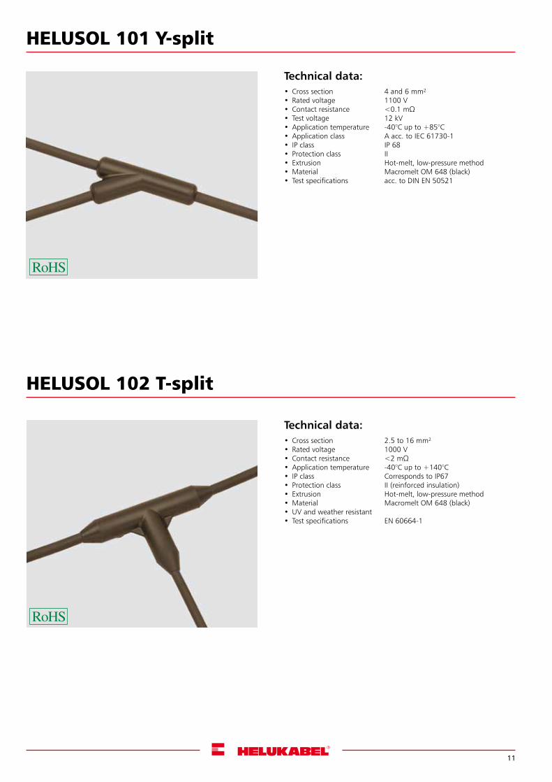
HELUSOL 101 Y-split
Technical data:• Cross section 4 and 6 mm²• Rated voltage 1100 V• Contactresistance <0.1mΩ• Test voltage 12 kV•Application temperature -40°C up to +85°C•Application class A acc. to IEC 61730-1• IP class IP 68• Protection class II• Extrusion Hot-melt, low-pressure method•Material Macromelt OM 648 (black)• Test specifications acc. to DIN EN 50521
HELUSOL 102 T-split
Technical data:• Cross section 2.5 to 16 mm²• Rated voltage 1000 V• Contactresistance <2mΩ•Application temperature -40°C up to +140°C• IP class Corresponds to IP67• Protection class II (reinforced insulation)• Extrusion Hot-melt, low-pressure method•Material Macromelt OM 648 (black)•UV and weather resistant• Test specifications EN 60664-1
12
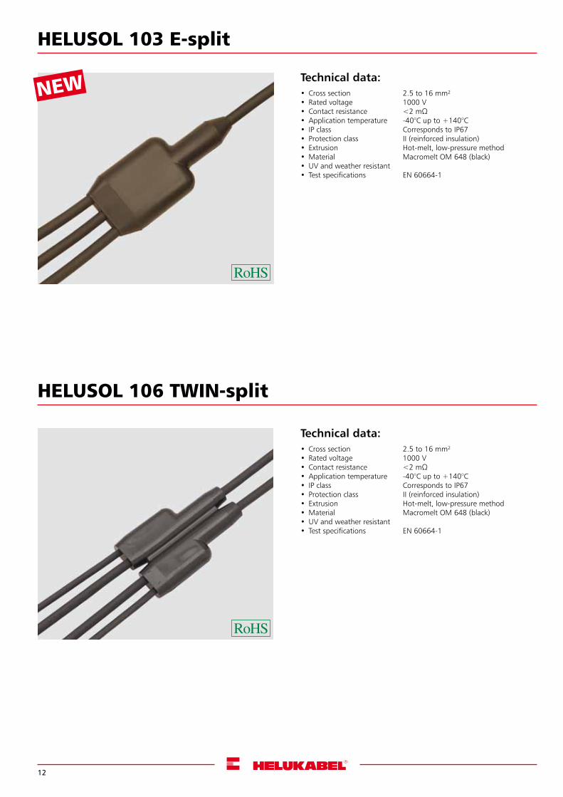
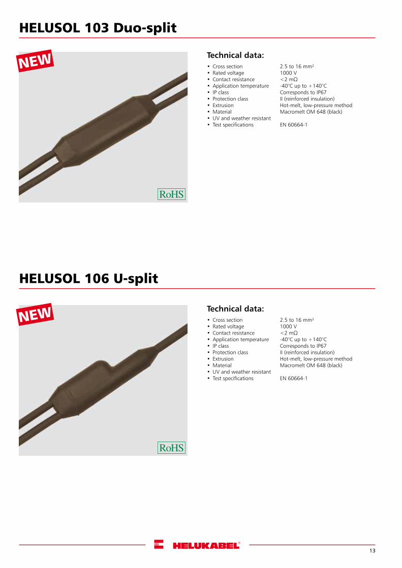
NEW Technical data:• Cross section 2.5 to 16 mm²• Rated voltage 1000 V• Contactresistance <2mΩ•Application temperature -40°C up to +140°C• IP class Corresponds to IP67• Protection class II (reinforced insulation)• Extrusion Hot-melt, low-pressure method•Material Macromelt OM 648 (black)•UV and weather resistant• Test specifications EN 60664-1
Technical data:• Cross section 2.5 to 16 mm²• Rated voltage 1000 V• Contactresistance <2mΩ•Application temperature -40°C up to +140°C• IP class Corresponds to IP67• Protection class II (reinforced insulation)• Extrusion Hot-melt, low-pressure method•Material Macromelt OM 648 (black)•UV and weather resistant• Test specifications EN 60664-1
HELUSOL 103 E-split
HELUSOL 106 TWIN-split
13
NEW
NEW
Technical data:• Cross section 2.5 to 16 mm²• Rated voltage 1000 V• Contactresistance <2mΩ•Application temperature -40°C up to +140°C• IP class Corresponds to IP67• Protection class II (reinforced insulation)• Extrusion Hot-melt, low-pressure method•Material Macromelt OM 648 (black)•UV and weather resistant• Test specifications EN 60664-1
Technical data:• Cross section 2.5 to 16 mm²• Rated voltage 1000 V• Contactresistance <2mΩ•Application temperature -40°C up to +140°C• IP class Corresponds to IP67• Protection class II (reinforced insulation)• Extrusion Hot-melt, low-pressure method•Material Macromelt OM 648 (black)•UV and weather resistant• Test specifications EN 60664-1
HELUSOL 103 Duo-split
HELUSOL 106 U-split
14
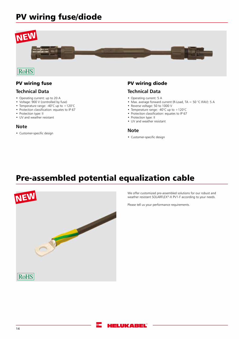
NEWWe offer customized pre-assembled solutions for our robust and weather resistant SOLARFLEX®-X PV1-F according to your needs.
Please tell us your performance requirements.
Pre-assembled potential equalization cable
Copy and
fax straight to
+49 7150 959225
NEW
PV wiring fuse/diode
PV wiring diode
Technical Data•Operating current: 5 A•Max. average forward current (R-Load, TA = 50 °C IFAV): 5 A• Reverse voltage: 50 to 1000 V• Temperature range: -40°C up to +120°C• Protection classification: equates to IP 67• Protection type: II•UV and weather resistant
Note• Customer-specific design
PV wiring fuse
Technical Data•Operating current: up to 20 A• Voltage: 900 V (controlled by fuse)• Temperature range: -40°C up to +120°C• Protection classification: equates to IP 67• Protection type: II•UV and weather resistant
Note• Customer-specific design
15
Connector 1 Connector 2 Connector 3
MC4 2.5-10 mm²
MC3 2.5-6 mm²
HC3 2.5-6 mm²
H4 2.5-10 mm²
Sunclix 2.5-6 mm²
Please enter: Mc=male connector, Fc=female connector
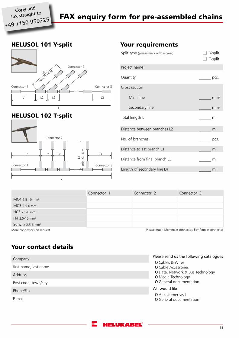
FAX enquiry form for pre-assembled chains
Project name
Quantity ______ pcs.
Cross section
Main line ______ mm²
Secondary line ______ mm²
Total length L ______ m
HELUSOL 101 Y-split
Company
first name, last name
Address
Post code, town/city
Phone/Fax
Your contact detailsPlease send us the following cataloguesO Cables & WiresO Cable AccessoriesO Data, Network & Bus TechnologyO Media TechnologyO General documentation
We would likeO A customer visitO General documentation
Distance between branches L2 ______ m
No. of branches ______ pcs.
Distance to 1st branch L1 ______ m
Distance from final branch L3 ______ m
Length of secondary line L4 ______ m
Copy and
fax straight to
+49 7150 959225
Connector 1 Connector 3
Connector 2
L1 L2 L2
L
L4
min. 0.16 m
L3
L1 L2 L2
L
L3
HELUSOL 102 T-split
Connector 1 Connector 3
Connector 2
L
L4m
in. 0
.16
m
Your requirementsSplit type (please mark with a cross) Y-split
T-split
More connectors on request
16
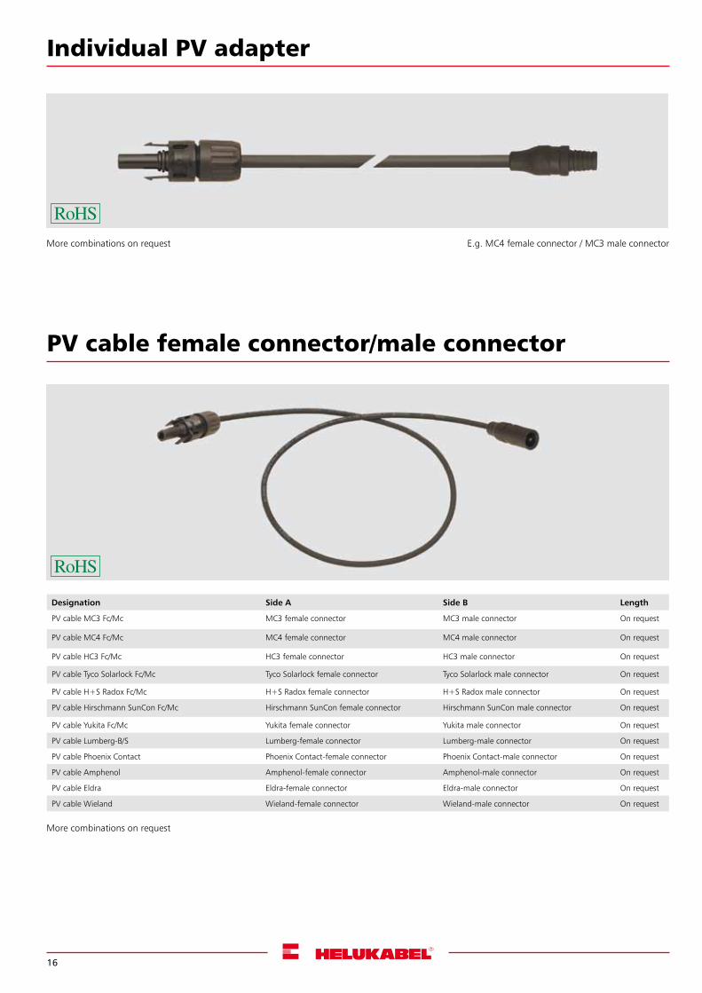
PV cable female connector/male connector
Designation Side A Side B Length
PV cable MC3 Fc/Mc MC3 female connector MC3 male connector On request
PV cable MC4 Fc/Mc MC4 female connector MC4 male connector On request
PV cable HC3 Fc/Mc HC3 female connector HC3 male connector On request
PV cable Tyco Solarlock Fc/Mc Tyco Solarlock female connector Tyco Solarlock male connector On request
PV cable H+S Radox Fc/Mc H+S Radox female connector H+S Radox male connector On request
PV cable Hirschmann SunCon Fc/Mc Hirschmann SunCon female connector Hirschmann SunCon male connector On request
PV cable Yukita Fc/Mc Yukita female connector Yukita male connector On request
PV cable Lumberg-B/S Lumberg-female connector Lumberg-male connector On request
PV cable Phoenix Contact Phoenix Contact-female connector Phoenix Contact-male connector On request
PV cable Amphenol Amphenol-female connector Amphenol-male connector On request
PV cable Eldra Eldra-female connector Eldra-male connector On request
PV cable Wieland Wieland-female connector Wieland-male connector On request
Individual PV adapter
More combinations on request E.g. MC4 female connector / MC3 male connector
More combinations on request
17
Copy and
fax straight to
+49 7150 959225FAX enquiry form for PV cables
Company
first name, last name
Address
Post code, town/city
Phone/Fax
Your contact details
Please send us the following cataloguesO Cables & WiresO Cable AccessoriesO Data, Network & Bus TechnologyO Media TechnologyO General documentation
We would likeO A customer visitO General documentation
Project name
Quantity ______ pcs.
Cross section ______ mm²
Total length L ______ m
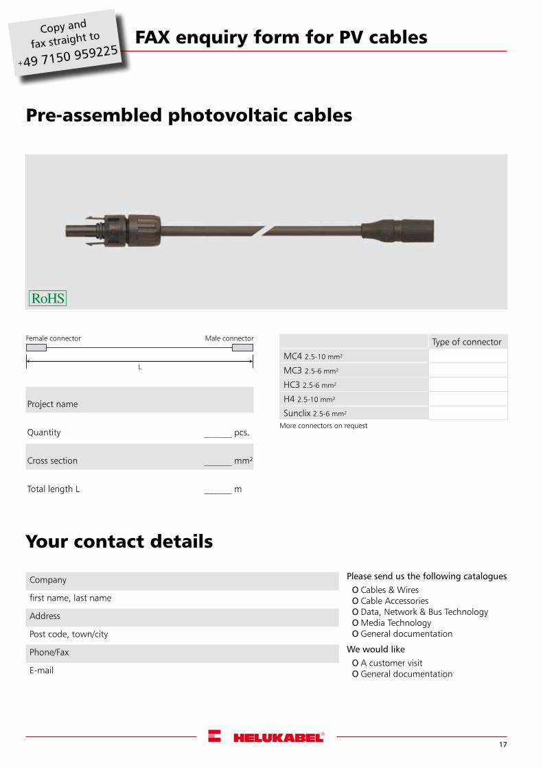
Pre-assembled photovoltaic cables
Female connector Male connector
L
Type of connector
MC4 2.5-10 mm²
MC3 2.5-6 mm²
HC3 2.5-6 mm²
H4 2.5-10 mm²
Sunclix 2.5-6 mm²
More connectors on request
18
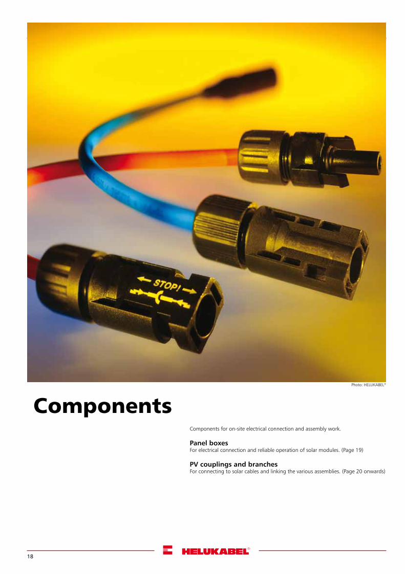
Components for on-site electrical connection and assembly work.
Panel boxesFor electrical connection and reliable operation of solar modules. (Page 19)
PV couplings and branchesFor connecting to solar cables and linking the various assemblies. (Page 20 onwards)
ComponentsPhoto: HELUKABEL®
19
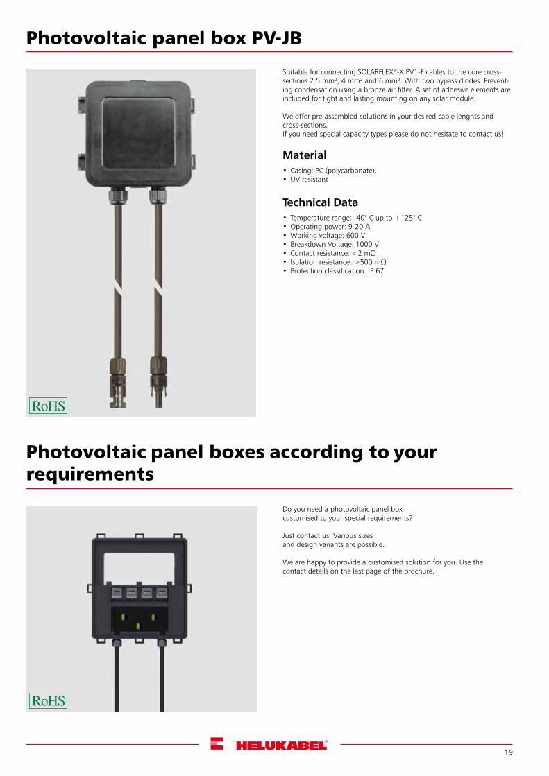
Photovoltaic panel box PV-JB
Suitable for connecting SOLARFLEX®-X PV1-F cables to the core cross-sections 2.5 mm², 4 mm² and 6 mm². With two bypass diodes. Prevent-ing condensation using a bronze air filter. A set of adhesive elements are included for tight and lasting mounting on any solar module.
We offer pre-assembled solutions in your desired cable lenghts and cross-sections.If you need special capacity types please do not hesitate to contact us!
Material• Casing: PC (polycarbonate), •UV-resistant
Technical Data• Temperature range: -40° C up to +125° C•Operating power: 9-20 A•Working voltage: 600 V• Breakdown Voltage: 1000 V• Contactresistance:<2mΩ• Isulationresistance:>500mΩ• Protection classification: IP 67
Photovoltaic panel boxes according to your requirements
Do you need a photovoltaic panel box customised to your special requirements?
Just contact us. Various sizes and design variants are possible.
We are happy to provide a customised solution for you. Use thecontact details on the last page of the brochure.
20
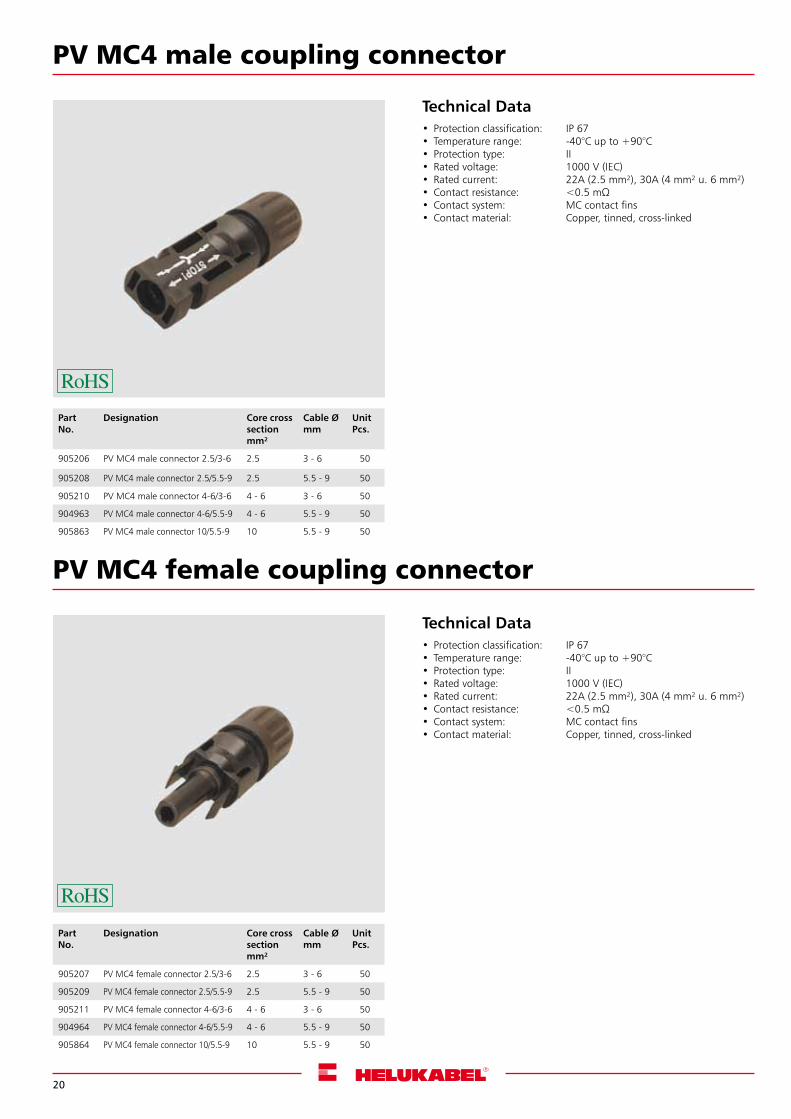
PV MC4 male coupling connector
Technical Data• Protection classification: IP 67• Temperature range: -40°C up to +90°C• Protection type: II• Rated voltage: 1000 V (IEC)• Rated current: 22A (2.5 mm²), 30A (4 mm² u. 6 mm²)• Contactresistance: <0.5mΩ• Contact system: MC contact fins• Contact material: Copper, tinned, cross-linked
PV MC4 female coupling connector
Technical Data• Protection classification: IP 67• Temperature range: -40°C up to +90°C• Protection type: II• Rated voltage: 1000 V (IEC)• Rated current: 22A (2.5 mm²), 30A (4 mm² u. 6 mm²)• Contactresistance: <0.5mΩ• Contact system: MC contact fins• Contact material: Copper, tinned, cross-linked
Part No.
Designation Core cross sectionmm²
Cable Ømm
UnitPcs.
905206 PV MC4 male connector 2.5/3-6 2.5 3 - 6 50
905208 PV MC4 male connector 2.5/5.5-9 2.5 5.5 - 9 50
905210 PV MC4 male connector 4-6/3-6 4 - 6 3 - 6 50
904963 PV MC4 male connector 4-6/5.5-9 4 - 6 5.5 - 9 50
905863 PV MC4 male connector 10/5.5-9 10 5.5 - 9 50
Part No.
Designation Core cross sectionmm²
Cable Ømm
UnitPcs.
905207 PV MC4 female connector 2.5/3-6 2.5 3 - 6 50
905209 PV MC4 female connector 2.5/5.5-9 2.5 5.5 - 9 50
905211 PV MC4 female connector 4-6/3-6 4 - 6 3 - 6 50
904964 PV MC4 female connector 4-6/5.5-9 4 - 6 5.5 - 9 50
905864 PV MC4 female connector 10/5.5-9 10 5.5 - 9 50
21
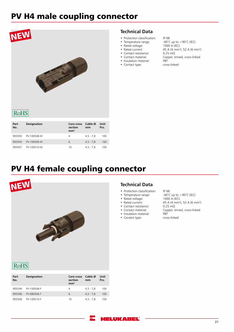
PV H4 male coupling connector
Technical Data• Protection classification: IP 68• Temperature range: -40°C up to +90°C (IEC)• Rated voltage: 1000 A (IEC)• Rated current: 45 A (4 mm²), 52 A (6 mm²)• Contactresistance: 0.25mΩ• Contact material: Copper, tinned, cross-linked• Insulation material: PBT• Conatct type: cross-linked
PV H4 female coupling connector
Technical Data• Protection classification: IP 68• Temperature range: -40°C up to +90°C (IEC)• Rated voltage: 1000 A (IEC)• Rated current: 45 A (4 mm²), 52 A (6 mm²)• Contactresistance: 0.25mΩ• Contact material: Copper, tinned, cross-linked• Insulation material: PBT• Contact type: cross-linked
Part No.
Designation Core cross sectionmm²
Cable Ømm
UnitPcs.
905593 PV-100508-M 4 4,5 - 7,8 100
905595 PV-100506-M 6 4,5 - 7,8 100
905937 PV-100510-M 10 4.5 - 7.8 100
Part No.
Designation Core cross sectionmm²
Cable Ømm
UnitPcs.
905594 PV-100508-F 4 4,5 - 7,8 100
905596 PV-080506-F 6 4,5 - 7,8 100
905938 PV-100510-F 10 4.5 - 7.8 100
NEW
NEW
22
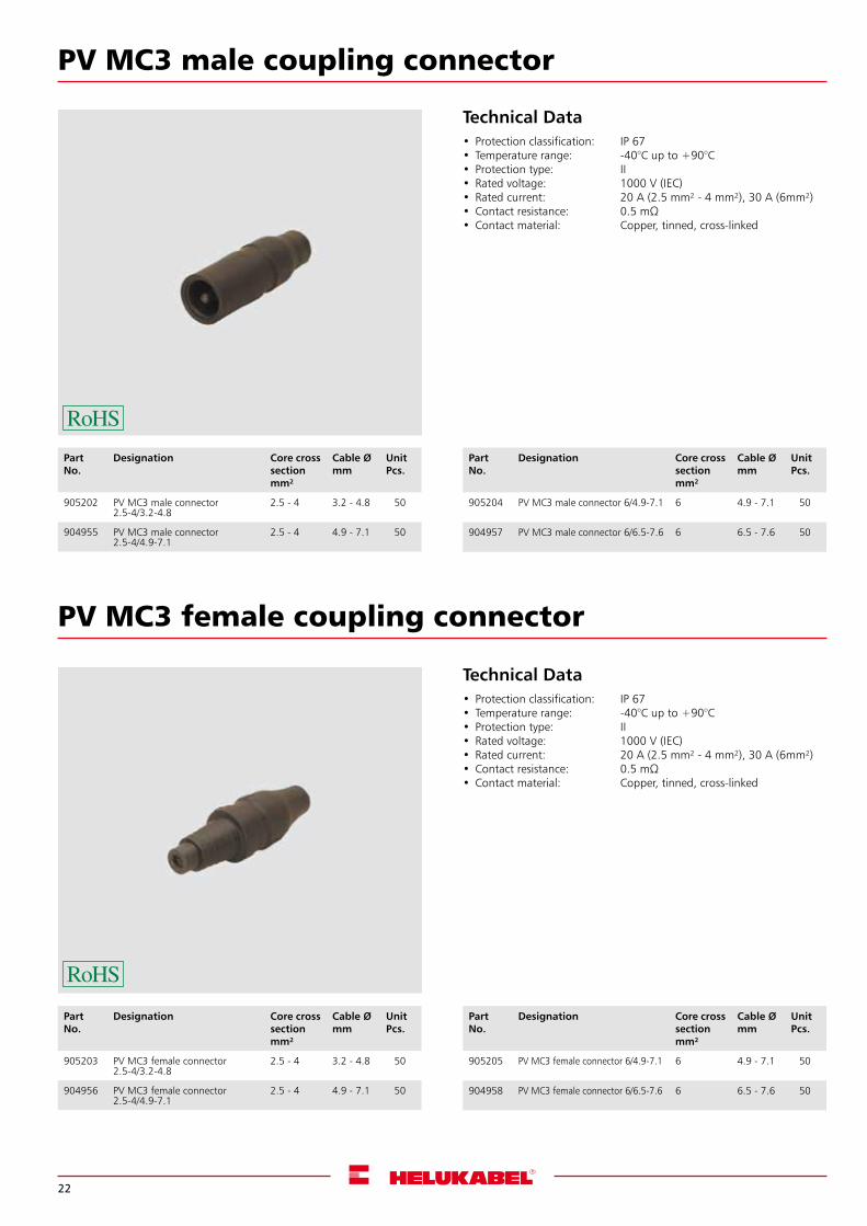
PV MC3 male coupling connector
PV MC3 female coupling connector
Technical Data• Protection classification: IP 67• Temperature range: -40°C up to +90°C• Protection type: II• Rated voltage: 1000 V (IEC)• Rated current: 20 A (2.5 mm² - 4 mm²), 30 A (6mm²)• Contactresistance: 0.5mΩ• Contact material: Copper, tinned, cross-linked
Technical Data• Protection classification: IP 67• Temperature range: -40°C up to +90°C• Protection type: II• Rated voltage: 1000 V (IEC)• Rated current: 20 A (2.5 mm² - 4 mm²), 30 A (6mm²)• Contactresistance: 0.5mΩ• Contact material: Copper, tinned, cross-linked
Part No.
Designation Core cross sectionmm²
Cable Ømm
UnitPcs.
905202 PV MC3 male connector 2.5-4/3.2-4.8
2.5 - 4 3.2 - 4.8 50
904955 PV MC3 male connector 2.5-4/4.9-7.1
2.5 - 4 4.9 - 7.1 50
Part No.
Designation Core cross sectionmm²
Cable Ømm
UnitPcs.
905203 PV MC3 female connector 2.5-4/3.2-4.8
2.5 - 4 3.2 - 4.8 50
904956 PV MC3 female connector 2.5-4/4.9-7.1
2.5 - 4 4.9 - 7.1 50
Part No.
Designation Core cross sectionmm²
Cable Ømm
UnitPcs.
905204 PV MC3 male connector 6/4.9-7.1 6 4.9 - 7.1 50
904957 PV MC3 male connector 6/6.5-7.6 6 6.5 - 7.6 50
Part No.
Designation Core cross sectionmm²
Cable Ømm
UnitPcs.
905205 PV MC3 female connector 6/4.9-7.1 6 4.9 - 7.1 50
904958 PV MC3 female connector 6/6.5-7.6 6 6.5 - 7.6 50
23
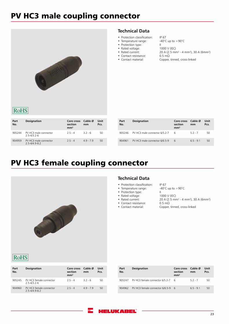
PV HC3 male coupling connector
Technical Data• Protection classification: IP 67• Temperature range: -40°C up to +90°C• Protection type: II• Rated voltage: 1000 V (IEC)• Rated current: 20 A (2.5 mm² - 4 mm²), 30 A (6mm²)• Contactresistance: 0.5mΩ• Contact material: Copper, tinned, cross-linked
Part No.
Designation Core cross sectionmm²
Cable Ømm
UnitPcs.
905244 PV HC3 male connector 2.5-4/3.2-6
2.5 - 4 3.2 - 6 50
904959 PV HC3 male connector 2.5-4/4.9-8.2
2.5 - 4 4.9 - 7.9 50
PV HC3 female coupling connector
Technical Data• Protection classification: IP 67• Temperature range: -40°C up to +90°C• Protection type: II• Rated voltage: 1000 V (IEC)• Rated current: 20 A (2.5 mm² - 4 mm²), 30 A (6mm²)• Contactresistance: 0.5mΩ• Contact material: Copper, tinned, cross-linked
Part No.
Designation Core cross sectionmm²
Cable Ømm
UnitPcs.
905245 PV HC3 female connector 2.5-4/3.2-6
2.5 - 4 3.2 - 6 50
904960 PV HC3 female connector 2.5-4/4.9-8.2
2.5 - 4 4.9 - 7.9 50
Part No.
Designation Core cross sectionmm²
Cable Ømm
UnitPcs.
905247 PV HC3 female connector 6/5.2-7 6 5.2 - 7 50
904962 PV HC3 female connector 6/6.5-9 6 6.5 - 9.1 50
Part No.
Designation Core cross sectionmm²
Cable Ømm
UnitPcs.
905246 PV HC3 male connector 6/5.2-7 6 5.2 - 7 50
904961 PV HC3 male connector 6/6.5-9 6 6.5 - 9.1 50
24
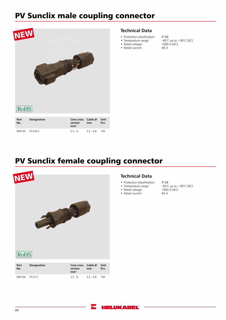
PV Sunclix male coupling connector
PV Sunclix female coupling connector
Technical Data• Protection classification: IP 68• Temperature range: -40°C up to +90°C (IEC)• Rated voltage: 1000 A (IEC)• Rated current: 40 A
Technical Data• Protection classification: IP 68• Temperature range: -40°C up to +90°C (IEC)• Rated voltage: 1000 A (IEC)• Rated current: 40 A
Part No.
Designation Core cross sectionmm²
Cable Ømm
UnitPcs.
909165 PV-CM-S 2.5 - 6 3.2 - 4.8 100
Part No.
Designation Core cross sectionmm²
Cable Ømm
UnitPcs.
906166 PV-CF-S 2.5 - 6 3.2 - 4.8 100
NEW
NEW
25
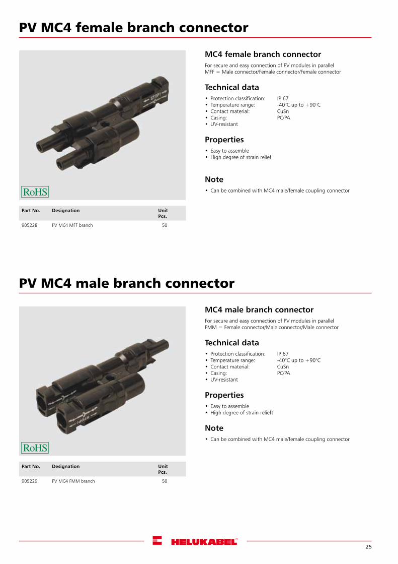
PV MC4 female branch connector
PV MC4 male branch connector
Part No. Designation UnitPcs.
905228 PV MC4 MFF branch 50
Part No. Designation UnitPcs.
905229 PV MC4 FMM branch 50
MC4 female branch connector For secure and easy connection of PV modules in parallelMFF = Male connector/Female connector/Female connector
Technical data• Protection classification: IP 67• Temperature range: -40°C up to +90°C• Contact material: CuSn• Casing: PC/PA•UV-resistant
Properties• Easy to assemble•High degree of strain relief
Note• Can be combined with MC4 male/female coupling connector
MC4 male branch connectorFor secure and easy connection of PV modules in parallelFMM = Female connector/Male connector/Male connector
Technical data• Protection classification: IP 67• Temperature range: -40°C up to +90°C• Contact material: CuSn• Casing: PC/PA•UV-resistant
Properties• Easy to assemble•High degree of strain relieft
Note• Can be combined with MC4 male/female coupling connector
26
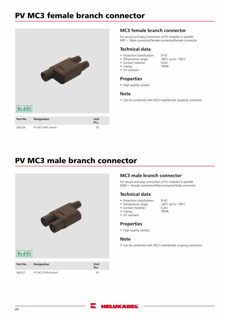
PV MC3 female branch connector
PV MC3 male branch connector
Part No. Designation UnitPcs.
905226 PV MC3 MFF branch 50
Part No. Designation UnitPcs.
905227 PV MC3 FMM branch 50
MC3 female branch connectorFor secure and easy connection of PV modules in parallelMFF = Male connector/Female connector/Female connector
Technical data• Protection classification: IP 67• Temperature range: -40°C up to +90°C• Contact material: CuSn• Casing: TPEPA•UV resistant
Properties•High-quality contact
Note• Can be combined with MC3 male/female coupling connector
MC3 male branch connectorFor secure and easy connection of PV modules in parallelFMM = Female connector/Male connector/Male connector
Technical data• Protection classification: IP 67• Temperature range: -40°C up to +90°C• Contact material: CuSn• Casing: TPEPA•UV resistant
Properties•High-quality contact
Note• Can be combined with MC3 male/female coupling connector
27
Cable accessories
28
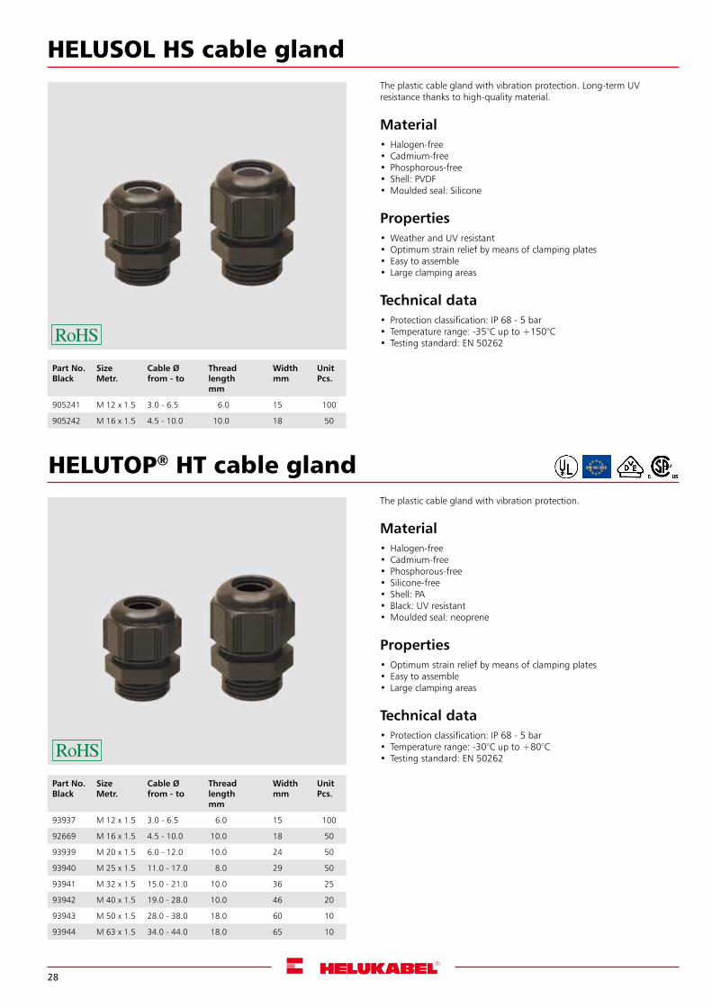
HELUSOL HS cable gland
Part No.Black
SizeMetr.
Cable Ø from - to
Thread length mm
Widthmm
UnitPcs.
905241 M 12 x 1.5 3.0 - 6.5 6.0 15 100
905242 M 16 x 1.5 4.5 - 10.0 10.0 18 50
The plastic cable gland with vibration protection. Long-term UV resistance thanks to high-quality material.
Material•Halogen-free• Cadmium-free• Phosphorous-free• Shell: PVDF•Moulded seal: Silicone
Properties•Weather and UV resistant•Optimum strain relief by means of clamping plates• Easy to assemble• Large clamping areas
Technical data• Protection classification: IP 68 - 5 bar• Temperature range: -35°C up to +150°C• Testing standard: EN 50262
HELUTOP® HT cable gland
Part No.Black
SizeMetr.
Cable Øfrom - to
Thread length mm
Widthmm
UnitPcs.
93937 M 12 x 1.5 3.0 - 6.5 6.0 15 100
92669 M 16 x 1.5 4.5 - 10.0 10.0 18 50
93939 M 20 x 1.5 6.0 - 12.0 10.0 24 50
93940 M 25 x 1.5 11.0 - 17.0 8.0 29 50
93941 M 32 x 1.5 15.0 - 21.0 10.0 36 25
93942 M 40 x 1.5 19.0 - 28.0 10.0 46 20
93943 M 50 x 1.5 28.0 - 38.0 18.0 60 10
93944 M 63 x 1.5 34.0 - 44.0 18.0 65 10
The plastic cable gland with vibration protection.
Material•Halogen-free• Cadmium-free• Phosphorous-free• Silicone-free• Shell: PA• Black: UV resistant•Moulded seal: neoprene
Properties•Optimum strain relief by means of clamping plates• Easy to assemble• Large clamping areas
Technical data• Protection classification: IP 68 - 5 bar• Temperature range: -30°C up to +80°C• Testing standard: EN 50262
29
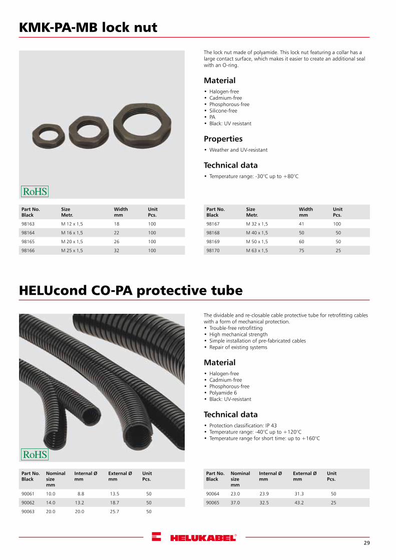
KMK-PA-MB lock nut
The lock nut made of polyamide. This lock nut featuring a collar has a large contact surface, which makes it easier to create an additional seal with an O-ring.
Material•Halogen-free• Cadmium-free• Phosphorous-free• Silicone-free• PA• Black: UV resistant
Properties•Weather and UV-resistant
Technical data• Temperature range: -30°C up to +80°C
HELUcond CO-PA protective tube
The dividable and re-closable cable protective tube for retrofitting cables with a form of mechanical protection.• Trouble-free retrofitting•High mechanical strength• Simple installation of pre-fabricated cables• Repair of existing systems
Material•Halogen-free• Cadmium-free• Phosphorous-free• Polyamide 6• Black: UV-resistant
Technical data• Protection classification: IP 43• Temperature range: -40°C up to +120°C• Temperature range for short time: up to +160°C
Part No.Black
Nominal sizemm
Internal Ømm
External Ø mm
UnitPcs.
90061 10.0 8.8 13.5 50
90062 14.0 13.2 18.7 50
90063 20.0 20.0 25.7 50
Part No.Black
SizeMetr.
Widthmm
UnitPcs.
98163 M 12 x 1,5 18 100
98164 M 16 x 1,5 22 100
98165 M 20 x 1,5 26 100
98166 M 25 x 1,5 32 100
Part No.Black
SizeMetr.
Widthmm
UnitPcs.
98167 M 32 x 1,5 41 100
98168 M 40 x 1,5 50 50
98169 M 50 x 1,5 60 50
98170 M 63 x 1,5 75 25
Part No.Black
Nominal sizemm
Internal Ømm
External Ø mm
UnitPcs.
90064 23.0 23.9 31.3 50
90065 37.0 32.5 43.2 25
30
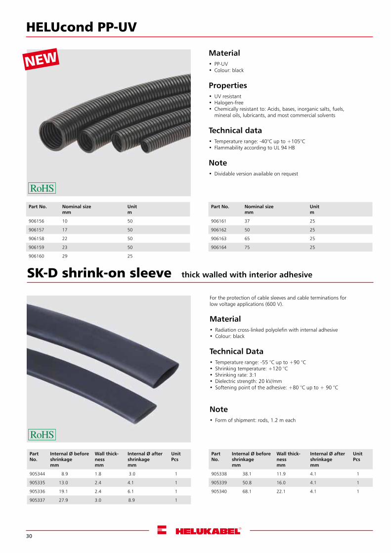
SK-D shrink-on sleeve thick walled with interior adhesive
For the protection of cable sleeves and cable terminations for low voltage applications (600 V).
Material• Radiation cross-linked polyolefin with internal adhesive• Colour: black
Technical Data• Temperature range: -55 °C up to +90 °C• Shrinking temperature: +120 °C• Shrinking rate: 3:1•Dielectric strength: 20 kV/mm• Softening point of the adhesive: +80 °C up to + 90 °C
Note• Form of shipment: rods, 1.2 m each
Part No.
Internal Ø before shrinkagemm
Wall thick-nessmm
Internal Ø after shrinkage mm
UnitPcs
905344 8.9 1.8 3.0 1
905335 13.0 2.4 4.1 1
905336 19.1 2.4 6.1 1
905337 27.9 3.0 8.9 1
Part No.
Internal Ø before shrinkagemm
Wall thick-nessmm
Internal Ø after shrinkage mm
UnitPcs
905338 38.1 11.9 4.1 1
905339 50.8 16.0 4.1 1
905340 68.1 22.1 4.1 1
HELUcond PP-UV
Material• PP-UV • Colour: black
Properties•UV resistant•Halogen-free• Chemically resistant to: Acids, bases, inorganic salts, fuels,
mineral oils, lubricants, and most commercial solvents
Technical data• Temperature range: -40°C up to +105°C• Flammability according to UL 94 HB
Note•Dividable version available on request
Part No. Nominal sizemm
Unitm
906156 10 50
906157 17 50
906158 22 50
906159 23 50
906160 29 25
Part No. Nominal sizemm
Unitm
906161 37 25
906162 50 25
906163 65 25
906164 75 25
NEW
31
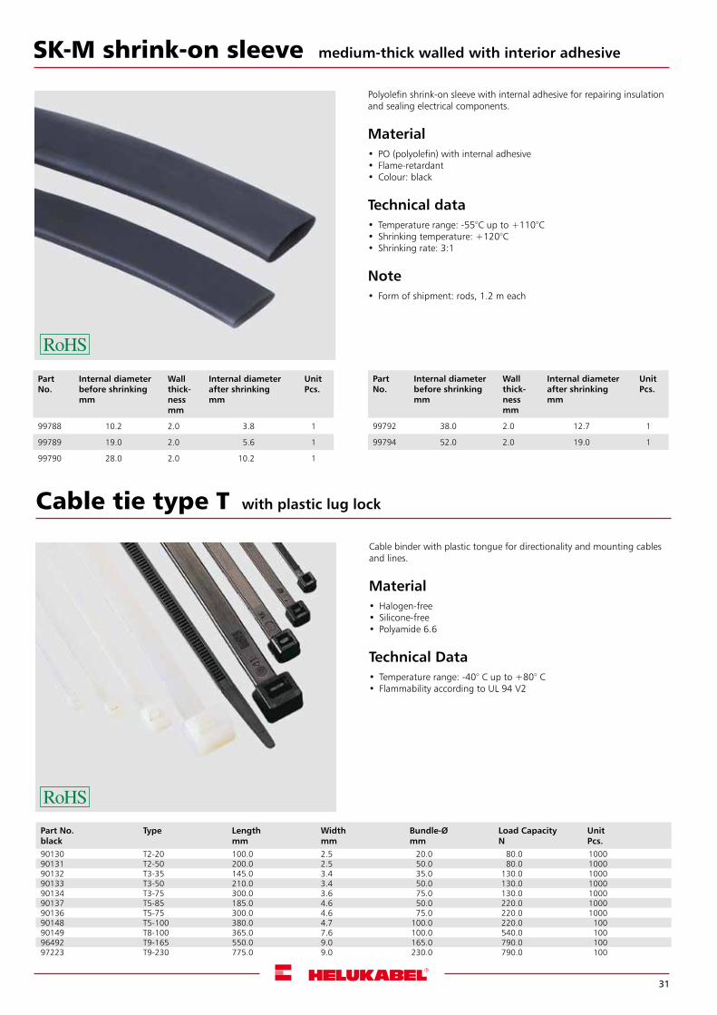
SK-M shrink-on sleeve
Polyolefin shrink-on sleeve with internal adhesive for repairing insulation and sealing electrical components.
Material• PO (polyolefin) with internal adhesive• Flame-retardant• Colour: black
Technical data• Temperature range: -55°C up to +110°C• Shrinking temperature: +120°C• Shrinking rate: 3:1
Note• Form of shipment: rods, 1.2 m each
Part No.
Internal diameter before shrinkingmm
Wall thick-nessmm
Internal diameter after shrinking mm
UnitPcs.
99788 10.2 2.0 3.8 1
99789 19.0 2.0 5.6 1
99790 28.0 2.0 10.2 1
Part No.
Internal diameter before shrinkingmm
Wall thick-nessmm
Internal diameter after shrinking mm
UnitPcs.
99792 38.0 2.0 12.7 1
99794 52.0 2.0 19.0 1
medium-thick walled with interior adhesive
Cable tie type T
Cable binder with plastic tongue for directionality and mounting cables and lines.
Material•Halogen-free• Silicone-free• Polyamide 6.6
Technical Data• Temperature range: -40° C up to +80° C• Flammability according to UL 94 V2
with plastic lug lock
Part No.black
Type Lengthmm
Widthmm
Bundle-Ømm
Load CapacityN
UnitPcs.
90130 T2-20 100.0 2.5 20.0 80.0 100090131 T2-50 200.0 2.5 50.0 80.0 100090132 T3-35 145.0 3.4 35.0 130.0 100090133 T3-50 210.0 3.4 50.0 130.0 100090134 T3-75 300.0 3.6 75.0 130.0 100090137 T5-85 185.0 4.6 50.0 220.0 100090136 T5-75 300.0 4.6 75.0 220.0 100090148 T5-100 380.0 4.7 100.0 220.0 10090149 T8-100 365.0 7.6 100.0 540.0 10096492 T9-165 550.0 9.0 165.0 790.0 10097223 T9-230 775.0 9.0 230.0 790.0 100
32
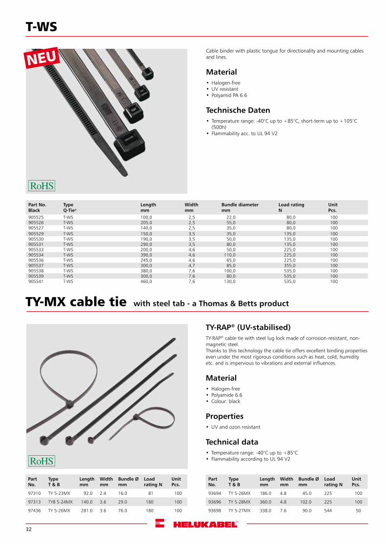
T-WS
Cable binder with plastic tongue for directionality and mounting cables and lines.
Material•Halogen-free•UV resistant• Polyamid PA 6.6
Technische Daten• Temperature range: -40°C up to +85°C, short-term up to +105°C
(500h)• Flammability acc. to UL 94 V2
Part No.Black
TypeQ-Tie®
Lengthmm
Widthmm
Bundle diametermm
Load ratingN
UnitPcs.
905525 T-WS 100,0 2,5 22,0 80,0 100905526 T-WS 205,0 2,5 55,0 80,0 100905527 T-WS 140,0 2,5 35,0 80,0 100905529 T-WS 150,0 3,5 35,0 135,0 100905530 T-WS 190,0 3,5 50,0 135,0 100905531 T-WS 290,0 3,5 80,0 135,0 100905533 T-WS 200,0 4,6 50,0 225,0 100905534 T-WS 390,0 4,6 110,0 225,0 100905536 T-WS 245,0 4,6 65,0 225,0 100905537 T-WS 300,0 4,7 85,0 355,0 100905538 T-WS 380,0 7,6 100,0 535,0 100905539 T-WS 300,0 7,6 80,0 535,0 100905541 T-WS 460,0 7,6 130,0 535,0 100
TY-MX cable tie
TY-RAP® (UV-stabilised)TY-RAP® cable tie with steel lug lock made of corrosion-resistant, non-magnetic steel.Thanks to this technology the cable tie offers excellent binding properties even under the most rigorous conditions such as heat, cold, humidity etc. and is impervious to vibrations and external influences.
Material•Halogen-free • Polyamide 6.6• Colour: black
Properties•UV and ozon resistant
Technical data• Temperature range: -40°C up to +85°C• Flammability according to UL 94 V2
with steel tab - a Thomas & Betts product
Part No.
TypeT & B
Lengthmm
Widthmm
Bundle Ømm
Load rating N
UnitPcs.
97310 TY 5-23MX 92.0 2.4 16.0 81 100
97313 TYB 5-24MX 140.0 3.6 29.0 180 100
97436 TY 5-26MX 281.0 3.6 76.0 180 100
Part No.
TypeT & B
Lengthmm
Widthmm
Bundle Ø mm
Load rating N
UnitPcs.
93694 TY 5-26MX 186.0 4.8 45.0 225 100
93696 TY 5-28MX 360.0 4.8 102.0 225 100
93698 TY 5-27MX 338.0 7.6 90.0 544 50

33
Cutting and strippingFor cutting and stripping solar cables. Can also be used with high-grade sheath material. (Page 34)
Crimping and assemblingThe contacts are neatly crimped for the purpose of connecting the solar cables to the connectors. If required, we can also offer specialist assembly accessories. (Page 35 onwards)
ToolsPhoto: HELUKABEL®
34
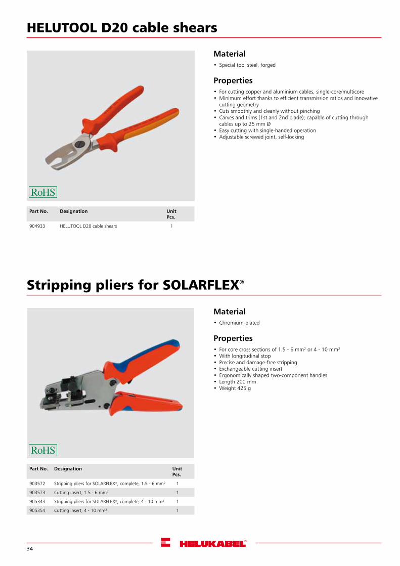
HELUTOOL D20 cable shears
Material• Special tool steel, forged
Properties• For cutting copper and aluminium cables, single-core/multicore• Minimum effort thanks to efficient transmission ratios and innovative
cutting geometry• Cuts smoothly and cleanly without pinching• Carves and trims (1st and 2nd blade); capable of cutting through
cables up to 25 mm Ø• Easy cutting with single-handed operation• Adjustable screwed joint, self-locking
Stripping pliers for SOLARFLEX®
Material• Chromium-plated
Properties• For core cross sections of 1.5 - 6 mm² or 4 - 10 mm²• With longitudinal stop• Precise and damage-free stripping• Exchangeable cutting insert• Ergonomically shaped two-component handles• Length 200 mm• Weight 425 g
Part No. Designation UnitPcs.
904933 HELUTOOL D20 cable shears 1
Part No. Designation UnitPcs.
903572 Stripping pliers for SOLARFLEX®, complete, 1.5 - 6 mm² 1
903573 Cutting insert, 1.5 - 6 mm² 1
905343 Stripping pliers for SOLARFLEX®, complete, 4 - 10 mm² 1
905354 Cutting insert, 4 - 10 mm² 1

35
HELUTOOL PEW 12.194 crimping tool
Suitable for crimping turned contacts MC3 and H4
Properties• For solderless electrical connections •Near-parallel crimping action • Consistently high crimping quality thanks to precision profiles and
positive lock (can be released) • Crimping pressure is set (calibrated) precisely at the factory • Leverage intensifies force to prevent fatigue when working • Ergonomically shaped grips • Various aids for precise positioning •All stressed parts made from special steel, which is oil-hardened and
tempered • Burnished head, grips fitted with plastic sleeves• For turned contacts, e.g. MC3• Length 200 mm •Weight 570 g
Part No. Designation Core cross sectionmm²
UnitPcs.
906151 HELUTOOL PEW 12.194 for MC3 1
906150 HELUTOOL PEW 12.1194 for H4 1
PV Tool Box HELUTOOL
Suitable for mounting MC3, MC4, H4 and other connecting systems(2.5 to 6 mm²)
Content• Crimping tool PEW with locator (upper and lower part)• Cable shear, up to 50 mm²• Stripping plier
Other combinations are available on request
Part No. Designation UnitPcs.
906168 PV Tool Box HELUTOOL I for MC3, HC3, H4 1
906169 PV Tool Box HELUTOOL II for MC3, HC3, Tyco, MC4 1
36
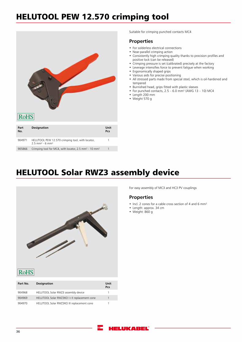
HELUTOOL PEW 12.570 crimping tool
Suitable for crimping punched contacts MC4
Properties• For solderless electrical connections •Near-parallel crimping action • Consistently high crimping quality thanks to precision profiles and
positive lock (can be released) • Crimping pressure is set (calibrated) precisely at the factory • Leverage intensifies force to prevent fatigue when working • Ergonomically shaped grips • Various aids for precise positioning •All stressed parts made from special steel, which is oil-hardened and
tempered • Burnished head, grips fitted with plastic sleeves• For punched contacts, 2.5 – 6.0 mm² (AWG 13 – 10) MC4• Length 200 mm•Weight 570 g
Part No.
Designation UnitPcs
904971 HELUTOOL PEW 12.570 crimping tool, with locator, 2.5 mm² - 6 mm²
1
905866 Crimping tool for MC4, with locator, 2.5 mm² - 10 mm² 1
HELUTOOL Solar RWZ3 assembly device
For easy assembly of MC3 and HC3 PV couplings
Properties• Incl. 2 cones for a cable cross section of 4 and 6 mm² • Length: approx. 34 cm•Weight: 860 g
Part No. Designation UnitPcs
904968 HELUTOOL Solar RWZ3 assembly device 1
904969 HELUTOOL Solar RWZ3KO I+II replacement cone 1
904970 HELUTOOL Solar RWZ3KO III replacement cone 1

37
HELUTOOL Solar H4 assembly spanner
For easy assembly of PV H4 couplings
Properties• For tightening and releasing the cable gland; for releasing the lock.•Assembly spanner set
Part No. Designation UnitPcs
905598 Opener 1
905599 Spanner 1
HELUTOOL Solar MC4 assembly spanner
For easy assembly of PV MC4 couplings
Properties• For tightening and releasing the cable gland; for releasing the lock.•Assembly spanner set
Part No. Designation UnitPcs
904972 HELUTOOL Solar MC4 assembly set, 2.5 - 6 mm² 1
9005865 HELUTOOL Solar MC4 assembly set, 10 mm² 1
Opener
Spanner
NEW
38
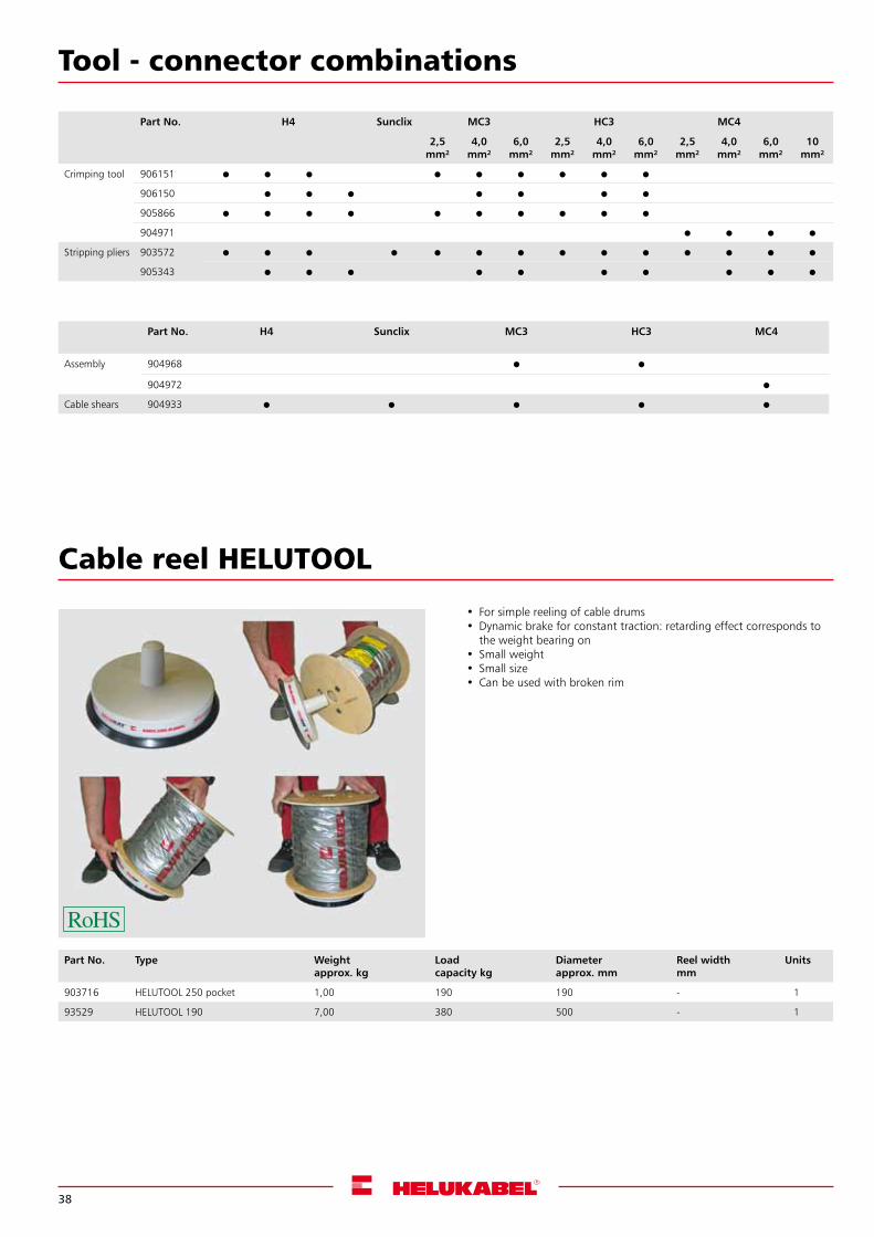
Cable reel HELUTOOL
Part No. Type Weightapprox. kg
Load capacity kg
Diameterapprox. mm
Reel widthmm
Units
903716 HELUTOOL 250 pocket 1,00 190 190 - 1
93529 HELUTOOL 190 7,00 380 500 - 1
• For simple reeling of cable drums•Dynamic brake for constant traction: retarding effect corresponds to
the weight bearing on• Small weight• Small size• Can be used with broken rim
Tool - connector combinations
Part No. H4 Sunclix MC3 HC3 MC4
Assembly 904968
904972
Cable shears 904933
Part No. H4 Sunclix MC3 HC3 MC4
2,5 mm²
4,0 mm²
6,0 mm²
2,5 mm²
4,0 mm²
6,0 mm²
2,5 mm²
4,0 mm²
6,0 mm²
10mm²
Crimping tool 906151
906150
905866
904971
Stripping pliers 903572
905343
39
PVC Control Cables page 40 onwards
Allweather and Rubber Cable page 44 onwards
Power Cables page 46 onwards
Installation Cables page 57
Medium Voltage Cables page 58 onwards
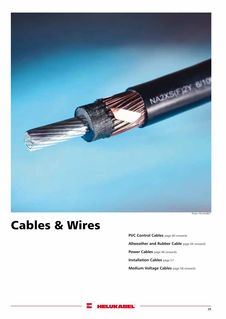
Cables & WiresPhoto: HELUKABEL®
40
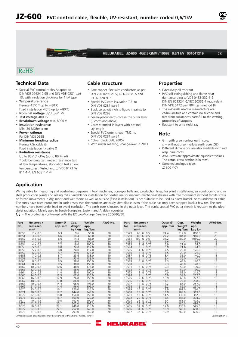
JZ-600 PVC control cable, flexible, UV-resistant, number coded 0,6/1kV
Technical Data• Special PVC control cables Adapted to
DIN VDE 0262/12.95 and DIN VDE 0281 part 13, with insulation thickness for 1 kV type
• Temperature rangeFlexing -15°C 1) up to +80°CFixed installation -40°C up to +80°C
•Nominal voltage U0/U 0,6/1 kV • Test voltage 4000 V •Breakdown voltage min. 8000 V • Insulation resistance
Min. 20 MOhm x km • Power ratingas
Per DIN VDE 0298 •Minimum bending radius
Flexing 7,5x cable ØFixed installation 4x cable Ø
•Radiation resistanceUp to 80x106 cJ/kg (up to 80 Mrad)1) cold bending test, impact resistance test at low temperatures, elongation test at low temperatures . Tested acc. to VDE 0473 Teil 811-1-4, EN 60811-1-4
ApplicationWiring cable for measuring and controlling purposes in tool machinery, conveyor belts and production lines, for plant installations, air conditioning and in steel production plants and rolling mills. Suitable for installation for flexible use for medium mechanical stresses with free movement without tensile stress or forced movements in dry, moist and wet rooms as well as outside (fixed installation). Is not suitable to be used as direct burrial- or as underwater cable. The cores have been numbered in such a way that the numbers are easily identifiable, even if the cable has only been stripped back a few cm. The core numbers have been underlined to avoid confusion. The earth core is located in the outer layer. The black, special PVC outer sheath is resistant to the ultra violet radiation. Mainly used in South-European, Eastern and Arabian countries. = The product is conformed with the EC Low-Voltage Directive 2006/95/EG.
Cable structure• Bare copper, fine wire conductors,as per
DIN VDE 0295 cl. 5, BS 6360 cl. 5 and IEC 60228 cl. 5
• Special PVC core insulation TI2, to DIN VDE 0281 part 1
• Black cores with white figure imprints to DIN VDE 0293
•Green-yellow earth core in the outer layer (3 cores and above)
• Cores stranded in layers with optimal lay-length
• Special PVC outer sheath TM2, to DIN VDE 0281 part 1
• Colour black (RAL 9005) •With meter marking, change-over in 2011
Properties• Extensively oil resistant • PVC self-extinguishing and flame retar-
dant according to VDE 0482-332-1-2, DIN EN 60332-1-2/ IEC 60332-1 (equivalent DIN VDE 0472 part 804 test method B)
• The materials used in manufacture are cadmium-free and contain no silicone and free from substances harmful to the wetting properties of lacquers
• Resistant to ultra violet ray
Note•G = with green-yellow earth core;
x = without green-yellow earth core (OZ).•Different dimensions are also available with red
resp. blue cores.•AWG sizes are approximate equivalent values.
The actual cross-section is in mm².• Screened analogue type:
JZ-600-Y-CY
Dimensions and specifications may be changed without prior notice. (RA01) Continuation »
Part No.
No.cores x cross-sec.mm²
Outer Øapp. mm
Cop. Weightkg / km
Weightapp. kg / km
AWG-No.
10550 2 x 0.5 6.3 9.6 56.0 2010551 3 G 0.5 6.6 14.4 68.0 2010552 3 x 0.5 6.6 14.4 68.0 2010553 4 G 0.5 7.2 19.0 100.0 2010554 4 x 0.5 7.2 19.0 100.0 2010555 5 G 0.5 8.0 24.0 117.0 2010556 5 x 0.5 8.0 24.0 117.0 2010557 6 G 0.5 8.7 29.0 126.0 2010558 7 G 0.5 8.7 33.6 138.0 2010559 7 x 0.5 8.7 33.6 138.0 2010560 8 G 0.5 9.5 38.0 150.0 2010561 8 x 0.5 9.5 38.0 150.0 2010562 10 G 0.5 10.6 48.0 176.0 2010563 12 G 0.5 11.4 58.0 200.0 2010564 12 x 0.5 11.4 58.0 200.0 2010565 14 G 0.5 12.3 67.0 230.0 2010566 16 G 0.5 12.9 76.0 250.0 2010567 18 G 0.5 13.8 86.0 276.0 2010568 20 G 0.5 14.4 96.0 293.0 2010569 21 G 0.5 14.4 96.0 305.0 2010570 25 G 0.5 16.1 120.0 335.0 2010571 30 G 0.5 17.2 144.0 348.0 2010572 32 G 0.5 18.0 154.0 355.0 2010573 34 G 0.5 18.7 163.0 520.0 2010574 40 G 0.5 19.5 192.0 590.0 2010575 42 G 0.5 20.1 202.0 595.0 2010576 50 G 0.5 22.1 240.0 715.0 2010577 52 G 0.5 22.1 252.0 740.0 2010578 61 G 0.5 23.6 293.0 840.0 20
Part No
No.cores x cross-sec.mm²
Outer Øapp. mm
Cop. Weightkg / km
Weightapp. kg / km
AWG-No.
10579 65 G 0.5 24.4 312.0 880.0 2010580 80 G 0.5 27.2 384.0 960.0 2010581 100 G 0.5 31.2 480.0 1050.0 2010582 2 x 0.75 6.6 14.4 66.0 1810583 3 G 0.75 6.9 21.6 74.0 1810584 3 x 0.75 6.9 21.6 74.0 1810585 4 G 0.75 7.5 29.0 126.0 1810586 4 x 0.75 7.5 29.0 126.0 1810587 5 G 0.75 8.4 36.0 140.0 1810588 5 x 0.75 8.4 36.0 140.0 1810589 6 G 0.75 9.3 43.0 170.0 1810590 6 x 0.75 9.3 43.0 170.0 1810591 7 G 0.75 9.3 50.0 190.0 1810592 7 x 0.75 9.3 50.0 190.0 1810593 8 G 0.75 10.0 58.0 212.0 1810594 8 x 0.75 10.0 58.0 212.0 1810595 9 G 0.75 10.9 65.0 227.0 1810596 10 G 0.75 11.1 72.0 238.0 1810597 12 G 0.75 12.2 86.0 257.0 1810598 12 x 0.75 12.2 86.0 257.0 1810599 14 G 0.75 12.9 101.0 286.0 1810600 15 G 0.75 13.8 108.0 319.0 1810601 18 G 0.75 14.5 130.0 362.0 1810602 20 G 0.75 15.4 144.0 394.0 1810603 21 G 0.75 15.4 151.0 422.0 1810604 25 G 0.75 17.2 180.0 486.0 1810605 32 G 0.75 19.0 230.0 595.0 1810606 34 G 0.75 19.9 245.0 638.0 1810607 37 G 0.75 19.9 260.0 696.0 18
41
Dimensions and specifications may be changed without prior notice. (RA01)
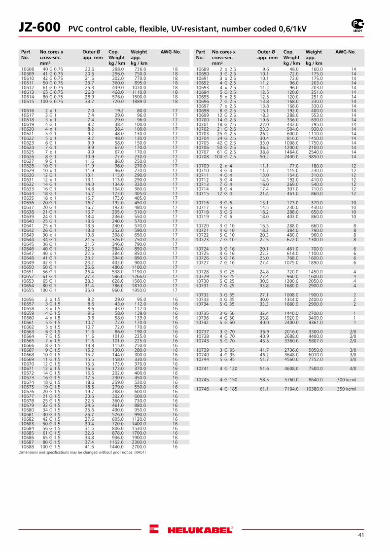
JZ-600 PVC control cable, flexible, UV-resistant, number coded 0,6/1kV
Part No.
No.cores x cross-sec.mm²
Outer Øapp. mm
Cop. Weightkg / km
Weightapp. kg / km
AWG-No.
10608 40 G 0.75 20.6 288.0 726.0 1810609 41 G 0.75 20.6 296.0 750.0 1810610 42 G 0.75 21.5 302.0 770.0 1810611 50 G 0.75 23.7 360.0 895.0 1810612 61 G 0.75 25.3 439.0 1070.0 1810613 65 G 0.75 26.0 468.0 1110.0 1810614 80 G 0.75 28.9 576.0 1500.0 1810615 100 G 0.75 33.2 720.0 1889.0 18
10616 2 x 1 7.0 19.2 80.0 1710617 3 G 1 7.4 29.0 96.0 1710618 3 x 1 7.4 29.0 96.0 1710619 4 G 1 8.2 38.4 100.0 1710620 4 x 1 8.2 38.4 100.0 1710621 5 G 1 9.2 48.0 130.0 1710622 5 x 1 9.2 48.0 130.0 1710623 6 G 1 9.9 58.0 150.0 1710624 7 G 1 9.9 67.0 170.0 1710625 7 x 1 9.9 67.0 170.0 1710626 8 G 1 10.9 77.0 230.0 1710627 9 G 1 11.6 86.0 250.0 1710628 10 G 1 11.9 96.0 270.0 1710629 10 x 1 11.9 96.0 270.0 1710630 12 G 1 13.1 115.0 290.0 1710631 12 x 1 13.1 115.0 290.0 1710632 14 G 1 14.0 134.0 320.0 1710633 16 G 1 14.8 154.0 360.0 1710634 18 G 1 15.7 173.0 405.0 1710635 18 x 1 15.7 173.0 405.0 1710636 20 G 1 16.7 192.0 450.0 1710637 20 G 1 16.7 192.0 480.0 1710638 21 G 1 16.7 205.0 510.0 1710639 24 G 1 18.4 236.0 550.0 1710640 25 G 1 18.6 240.0 570.0 1710641 25 x 1 18.6 240.0 570.0 1710642 26 G 1 18.8 252.0 590.0 1710643 30 x 1 19.8 308.0 650.0 1710644 34 G 1 21.5 326.0 750.0 1710645 36 G 1 21.5 346.0 790.0 1710646 40 G 1 22.5 384.0 850.0 1710647 40 x 1 22.5 384.0 850.0 1710648 41 G 1 23.2 394.0 890.0 1710649 42 G 1 23.2 403.0 900.0 1710650 50 G 1 25.6 480.0 1100.0 1710651 56 G 1 26.4 538.0 1190.0 1710652 61 G 1 27.3 586.0 1266.0 1710653 65 G 1 28.3 628.0 1560.0 1710654 80 G 1 31.4 786.0 1810.0 1710655 100 G 1 36.0 960.0 1950.0 17
10656 2 x 1.5 8.2 29.0 95.0 1610657 3 G 1.5 8.6 43.0 112.0 1610658 3 x 1.5 8.6 43.0 112.0 1610659 4 G 1.5 9.6 58.0 139.0 1610660 4 x 1.5 9.6 58.0 139.0 1610661 5 G 1.5 10.7 72.0 170.0 1610662 5 x 1.5 10.7 72.0 170.0 1610663 6 G 1.5 11.6 86.0 190.0 1610664 7 G 1.5 11.6 101.0 225.0 1610665 7 x 1.5 11.6 101.0 225.0 1610666 8 G 1.5 13.8 115.0 250.0 1610667 9 G 1.5 15.2 130.0 280.0 1610668 10 G 1.5 15.2 144.0 300.0 1610669 11 G 1.5 15.5 158.0 330.0 1610670 12 G 1.5 15.5 173.0 370.0 1610671 12 x 1.5 15.5 173.0 370.0 1610672 14 G 1.5 16.6 202.0 400.0 1610673 16 G 1.5 17.5 230.0 450.0 1610674 18 G 1.5 18.6 259.0 520.0 1610675 19 G 1.5 18.6 279.0 550.0 1610676 20 G 1.5 19.7 288.0 600.0 1610677 21 G 1.5 20.6 302.0 600.0 1610678 25 G 1.5 22.5 360.0 730.0 1610679 32 G 1.5 24.5 461.0 880.0 1610680 34 G 1.5 25.6 490.0 950.0 1610681 40 G 1.5 26.7 576.0 990.0 1610682 42 G 1.5 27.6 605.0 1120.0 1610683 50 G 1.5 30.4 720.0 1400.0 1610684 56 G 1.5 31.5 806.0 1530.0 1610685 61 G 1.5 32.6 878.0 1700.0 1610686 65 G 1.5 34.8 936.0 1900.0 1610687 80 G 1.5 37.4 1152.0 2300.0 1610688 100 G 1.5 41.6 1440.0 2700.0 16
Part No.
No.cores x cross-sec.mm²
Outer Øapp. mm
Cop. Weightkg / km
Weightapp. kg / km
AWG-No.
10689 2 x 2.5 9.6 48.0 160.0 1410690 3 G 2.5 10.1 72.0 175.0 1410691 3 x 2.5 10.1 72.0 175.0 1410692 4 G 2.5 11.2 96.0 203.0 14 10693 4 x 2.5 11.2 96.0 203.0 14 10694 5 G 2.5 12.5 120.0 251.0 1410695 5 x 2.5 12.5 120.0 251.0 1410696 7 G 2.5 13.8 168.0 330.0 1410697 7 x 2.5 13.8 168.0 330.0 1410698 8 G 2.5 15.1 192.0 400.0 1410699 12 G 2.5 18.3 288.0 553.0 1410700 14 G 2.5 19.6 336.0 630.0 1410701 18 G 2.5 22.0 432.0 795.0 1410702 21 G 2.5 23.3 504.0 930.0 1410703 25 G 2.5 26.2 600.0 1110.0 1410704 34 G 2.5 30.4 816.0 1450.0 1410705 42 G 2.5 33.0 1008.0 1750.0 1410706 50 G 2.5 36.2 1200.0 2100.0 1410707 61 G 2.5 38.8 1464.0 2540.0 1410708 100 G 2.5 50.2 2400.0 3850.0 14
10709 2 x 4 11.1 77.0 180.0 1210710 3 G 4 11.7 115.0 230.0 1210711 4 G 4 13.0 154.0 310.0 1210712 5 G 4 14.5 192.0 410.0 1210713 7 G 4 16.0 269.0 540.0 1210714 8 G 4 17.4 307.0 710.0 1210715 12 G 4 21.4 461.0 860.0 12
10716 3 G 6 13.1 173.0 370.0 1010717 4 G 6 14.5 230.0 430.0 1010718 5 G 6 16.2 288.0 650.0 1010719 7 G 6 18.0 403.0 860.0 10
10720 3 G 10 16.5 288.0 660.0 810721 4 G 10 18.2 384.0 790.0 810722 5 G 10 20.3 480.0 960.0 810723 7 G 10 22.5 672.0 1300.0 8
10724 3 G 16 20.1 461.0 700.0 610725 4 G 16 22.3 614.0 1100.0 610726 5 G 16 25.0 768.0 1600.0 610727 7 G 16 27.4 1075.0 1890.0 6
10728 3 G 25 24.8 720.0 1450.0 410729 4 G 25 27.4 960.0 1600.0 410730 5 G 25 30.5 1200.0 2050.0 410731 7 G 25 33.8 1680.0 2900.0 4
10732 3 G 35 27.1 1008.0 1900.0 210733 4 G 35 30.0 1344.0 2400.0 210734 5 G 35 33.3 1680.0 2900.0 2
10735 3 G 50 32.4 1440.0 2700.0 110736 4 G 50 35.8 1920.0 3400.0 110742 5 G 50 40.0 2400.0 4361.0 1
10737 3 G 70 36.9 2016.0 3300.0 2/010738 4 G 70 40.9 2688.0 4400.0 2/010743 5 G 70 45.5 3360.0 5807.0 2/0
10739 3 G 95 41.7 2736.0 5050.0 3/010740 4 G 95 46.2 3648.0 6010.0 3/010744 5 G 95 51.7 4560.0 7752.0 3/0
10741 4 G 120 51.6 4608.0 7500.0 4/0
10745 4 G 150 58.5 5760.0 8640.0 300 kcmil
10746 4 G 185 61.1 7104.0 10380.0 350 kcmil
42
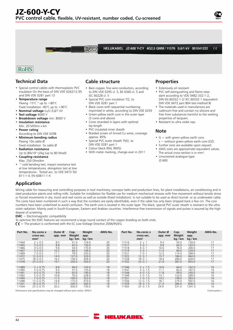
Technical Data• Special control cables with thermoplastic PVC
insulation On the basis of DIN VDE 0262/12.95 and DIN VDE 0281 part 13
• Temperature rangeFlexing -15°C 1) up to +80°CFixed installation -40°C up to +90°C
•Nominal voltage U0/U 0,6/1 kV • Test voltage 4000 V •Breakdown voltage min. 8000 V • Insulation resistance
Min. 20 MOhm x km • Power rating
According to DIN VDE 0298 •Minimum bending radius
Flexing 10x cable ØFixed installation 5x cable Ø
•Radiation resistanceUp to 80x106 cJ/kg (up to 80 Mrad)
•Coupling resistanceMax. 250 Ohm/km
• 1) cold bending test, impact resistance test at low temperatures, elongation test at low temperatures . Tested acc. to VDE 0473 Teil 811-1-4, EN 60811-1-4
ApplicationWiring cable for measuring and controlling purposes in tool machinery, conveyor belts and production lines, for plant installations, air conditioning and in steel production plants and rolling mills. Suitable for installation for flexible use for medium mechanical stresses with free movement without tensile stress or forced movements in dry, moist and wet rooms as well as outside (fixed installation). Is not suitable to be used as direct burrial- or as underwater cable. The cores have been numbered in such a way that the numbers are easily identifiable, even if the cable has only been stripped back a few cm. The core numbers have been underlined to avoid confusion. The earth core is located in the outer layer. The black, special PVC outer sheath is resistant to the ultra violet radiation. Mainly used in South-European, Eastern and Arabian countries. Interference-free transmission of signals and pulses is assured by the high degree of screening.EMC = Electromagnetic compatibilityTo optimise the EMC features we recommend a large round contact of the copper braiding on both ends. = The product is conformed with the EC Low-Voltage Directive 2006/95/EG.
Cable structure• Bare copper, fine wire conductors, according
to DIN VDE 0295 cl. 5, BS 6360 cl. 5 and IEC 60228 cl. 5
• Special PVC core insulation TI2, to DIN VDE 0281 part 1
• Black cores with sequential numbering imprinted in white, according to DIN VDE 0293
•Green-yellow earth core in the outer layer (3 cores and above)
• Cores stranded in layers with optimal lay-length
• PVC-insulated inner sheath • Braided screen of tinned Cu wires, coverage
approx. 85% • Special PVC outer sheath TM2, to
DIN VDE 0281 part 1 • Colour black (RAL 9005) •With meter marking, change-over in 2011
Properties• Extensively oil resistant• PVC self-extinguishing and flame retar-
dant according to VDE 0482-332-1-2, DIN EN 60332-1-2/ IEC 60332-1 (equivalent DIN VDE 0472 part 804 test method B)
• The materials used in manufacture are cadmium-free and contain no silicone and free from substances harmful to the wetting properties of lacquers
• Resistant to ultra violet rays
Note•G = with green-yellow earth core;
x = without green-yellow earth core (OZ).• Further sizes are available upon request.•AWG sizes are approximate equivalent values.
The actual cross-section is in mm².•Unscreened analogue type:
JZ-600
Dimensions and specifications may be changed without prior notice. (RA01) Continuation »
Part No. No.cores x cross-sec.mm²
Outer Øapp. mm
Cop. Weightkg / km
Weightapp. kg / km
AWG-No.
11464 2 x 0.5 8.5 41.0 129.0 2011465 3 G 0.5 8.8 45.0 150.0 2011466 4 G 0.5 9.6 54.0 170.0 2011467 5 G 0.5 10.2 66.0 199.0 2011469 7 G 0.5 11.1 79.0 235.0 2011472 12 G 0.5 14.0 137.0 320.0 2011475 18 G 0.5 16.2 156.0 428.0 2011478 25 G 0.5 19.1 250.0 503.0 20
11489 2 x 0.75 8.8 46.0 143.0 1811490 3 G 0.75 9.3 57.0 155.0 1811491 4 G 0.75 9.9 63.0 190.0 1811492 5 G 0.75 10.8 76.0 228.0 1811494 7 G 0.75 11.5 100.0 323.0 1811498 12 G 0.75 14.8 175.0 410.0 1811501 18 G 0.75 17.1 240.0 560.0 1811504 25 G 0.75 20.2 306.0 730.0 18
Part No. No.cores x cross-sec.mm²
Outer Øapp. mm
Cop. Weightkg / km
Weightapp. kg / km
AWG-No.
11516 2 x 1 9.4 54.0 150.0 1711517 3 G 1 9.8 64.0 163.0 1711518 4 G 1 10.6 76.0 200.0 1711519 5 G 1 11.4 89.0 239.0 1711521 7 G 1 12.5 114.0 289.0 1711525 12 G 1 15.7 186.0 464.0 1711528 18 G 1 18.4 284.0 628.0 1711532 25 G 1 21.6 387.0 855.0 17
11546 2 x 1.5 10.6 64.0 162.0 1611547 3 G 1.5 11.1 82.0 187.0 1611548 4 G 1.5 11.8 99.0 240.0 1611549 5 G 1.5 13.1 123.0 289.0 1611551 7 G 1.5 14.2 148.0 383.0 1611556 12 G 1.5 18.1 274.0 592.0 1611559 18 G 1.5 21.4 386.0 806.0 1611563 25 G 1.5 24.9 531.0 1241.0 16
JZ-600-Y-CYPVC control cable, flexible, UV-resistant, number coded, Cu-screened
43
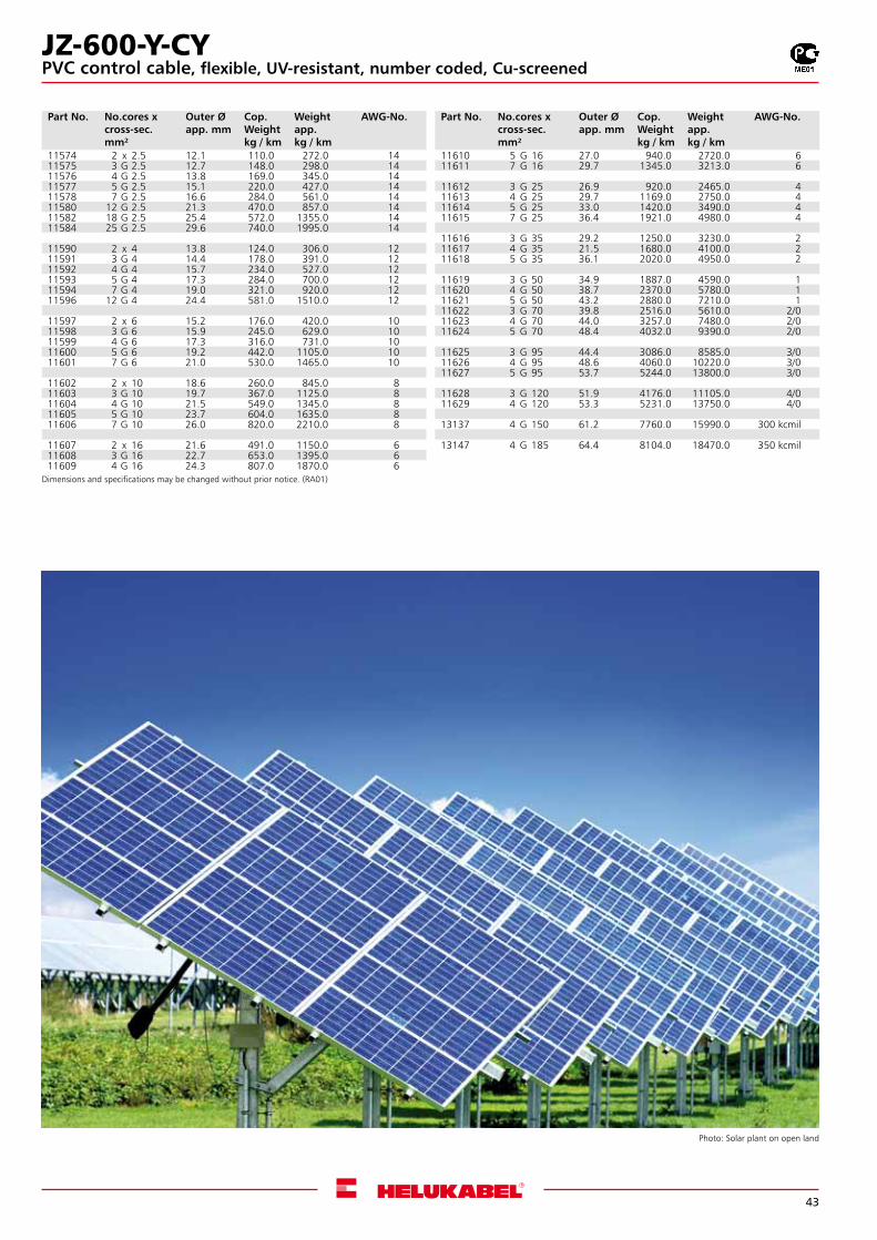
Photo: Solar plant on open land
Dimensions and specifications may be changed without prior notice. (RA01)
Part No. No.cores x cross-sec.mm²
Outer Øapp. mm
Cop. Weightkg / km
Weightapp. kg / km
AWG-No.
11574 2 x 2.5 12.1 110.0 272.0 1411575 3 G 2.5 12.7 148.0 298.0 1411576 4 G 2.5 13.8 169.0 345.0 1411577 5 G 2.5 15.1 220.0 427.0 1411578 7 G 2.5 16.6 284.0 561.0 1411580 12 G 2.5 21.3 470.0 857.0 1411582 18 G 2.5 25.4 572.0 1355.0 1411584 25 G 2.5 29.6 740.0 1995.0 14
11590 2 x 4 13.8 124.0 306.0 1211591 3 G 4 14.4 178.0 391.0 1211592 4 G 4 15.7 234.0 527.0 1211593 5 G 4 17.3 284.0 700.0 1211594 7 G 4 19.0 321.0 920.0 1211596 12 G 4 24.4 581.0 1510.0 12
11597 2 x 6 15.2 176.0 420.0 1011598 3 G 6 15.9 245.0 629.0 1011599 4 G 6 17.3 316.0 731.0 1011600 5 G 6 19.2 442.0 1105.0 1011601 7 G 6 21.0 530.0 1465.0 10
11602 2 x 10 18.6 260.0 845.0 811603 3 G 10 19.7 367.0 1125.0 811604 4 G 10 21.5 549.0 1345.0 811605 5 G 10 23.7 604.0 1635.0 811606 7 G 10 26.0 820.0 2210.0 8
11607 2 x 16 21.6 491.0 1150.0 611608 3 G 16 22.7 653.0 1395.0 611609 4 G 16 24.3 807.0 1870.0 6
Part No. No.cores x cross-sec.mm²
Outer Øapp. mm
Cop. Weightkg / km
Weightapp. kg / km
AWG-No.
11610 5 G 16 27.0 940.0 2720.0 611611 7 G 16 29.7 1345.0 3213.0 6
11612 3 G 25 26.9 920.0 2465.0 411613 4 G 25 29.7 1169.0 2750.0 411614 5 G 25 33.0 1420.0 3490.0 411615 7 G 25 36.4 1921.0 4980.0 4
11616 3 G 35 29.2 1250.0 3230.0 211617 4 G 35 21.5 1680.0 4100.0 211618 5 G 35 36.1 2020.0 4950.0 2
11619 3 G 50 34.9 1887.0 4590.0 111620 4 G 50 38.7 2370.0 5780.0 111621 5 G 50 43.2 2880.0 7210.0 111622 3 G 70 39.8 2516.0 5610.0 2/011623 4 G 70 44.0 3257.0 7480.0 2/011624 5 G 70 48.4 4032.0 9390.0 2/0
11625 3 G 95 44.4 3086.0 8585.0 3/011626 4 G 95 48.6 4060.0 10220.0 3/011627 5 G 95 53.7 5244.0 13800.0 3/0
11628 3 G 120 51.9 4176.0 11105.0 4/011629 4 G 120 53.3 5231.0 13750.0 4/0
13137 4 G 150 61.2 7760.0 15990.0 300 kcmil
13147 4 G 185 64.4 8104.0 18470.0 350 kcmil
JZ-600-Y-CYPVC control cable, flexible, UV-resistant, number coded, Cu-screened
44
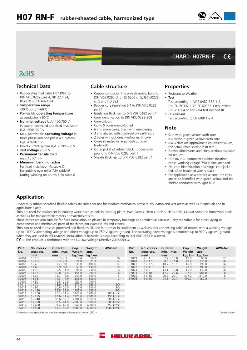
H07 RN-F rubber-sheated cable, harmonized type
Technical Data• Rubber sheathed cable H07 RN-F to
DIN VDE 0282 part 4, HD 22.4 S4, BS7919 = IEC 60245-4
• Temperature range-30°C up to +60°C
• Permissible operating temperatureat conductor +60°C
•Nominal voltage U0/U 450/750 Vin case of protected and fixed installationU0/U 600/1000 V
•Max. permissible operating voltage inthree phase and one phase a.c. systemU0/U 476/825 V
•Direct current-system U0/U 619/1238 V • Test voltage 2500 V • Permanent tensile load
max. 15 N/mm² •Minimum bending radius
For fixed installation 4x cable ØFor guiding over roller 7,5x cable ØDuring winding on drums 5-7x cable Ø
ApplicationHeavy duty rubber-sheathed flexible cables are suited for use for medium mechanical stress in dry, damp and wet areas as well as in open air and in agriculture plants.They are used for equipment in industry works such as boilers, heating plates, hand lamps, electric tools such as drills, circular saws and homework tools as well as for transportable motors or machines at site.These cables are also suitable for fixed installation on plaster, in temporary buildings and residential barracks. They are suitable for direct laying on components and mechanical parts of machines, for example lifts and cranes.They can be used in case of protected and fixed installation in tubes or in equipment as well as rotor connecting cable of motors with a working voltage up to 1000 V alternating voltage or a direct voltage up to 750 V against ground. The operating direct voltage is permitted up to 900 V against ground when they are used in rail-coaches. Installation in hazardous areas according to DIN VDE 0165 is allowed. = The product is conformed with the EC Low-Voltage Directive 2006/95/EG.
Cable structure• Copper conductor fine wire stranded, bare to
DIN VDE 0295 cl. 5, BS 6360 cl. 5, IEC 60228 cl. 5 and HD 383
• Rubber core insulation EI4 to DIN VDE 0282 part 1
• Insulation thickness to DIN VDE 0282 part 4 • Core identification to DIN VDE 0293-308 • Core colours•Up to 5 cores one-coloured• 6 and more cores, black with numbering• 3 and above, with green-yellow earth core• 2 cores without green-yellow earth core • Cores stranded in layers with optimal
lay-length •Outer jacket of rubber black, rubber com-
pound to DIN VDE 0282 part 1 • Sheath thickness to DIN VDE 0282 part 4
Properties• Resistant to Weather• Test
Test according to VDE 0482-332-1-2, DIN EN 60332-1-2/ IEC 60332-1 (equivalent DIN VDE 0472 part 804 test method B)
•Oil resistantTest according to EN 60811-2-1
Note•G = with green-yellow earth core
x = without green-yellow earth core•AWG sizes are approximate equivalent values,
the actual cross-section is in mm².• Further dimensions and cross-sections available
on request•H07 RN-F = harmonized rubber-sheathed
cable, working voltage 750 V, fine stranded.• Fhe core identification of a single core jacke-
ted, of an insulated wire is black• For application as a protective core, the ends
are to be identified with green-yellow and the middle conductor with light blue
Dimensions and specifications may be changed without prior notice. (RF01) Continuation »
Part No.
No. cores x cross-sec. mm²
Outer Ømin. - max. mm
Cop. Weightkg / km
Weightapp. kg / km
AWG-No.
37001 1 x 1.5 5.7 - 7.1 14.4 58.0 1637002 1 x 2.5 6.3 - 7.9 24.0 71.0 1437003 1 x 4 7.2 - 9.0 38.0 100.0 1237004 1 x 6 7.9 - 9.8 58.0 130.0 1037005 1 x 10 9.5 - 11.9 96.0 230.0 837006 1 x 16 10.8 - 13.4 154.0 290.0 637007 1 x 25 12.7 - 15.8 240.0 420.0 437008 1 x 35 14.3 - 17.9 336.0 530.0 237009 1 x 50 16.5 - 20.6 480.0 750.0 137010 1 x 70 18.6 - 23.3 672.0 960.0 2/037011 1 x 95 20.8 - 26.0 912.0 1250.0 3/037012 1 x 120 22.8 - 28.6 1152.0 1560.0 4/037013 1 x 150 25.2 - 31.4 1440.0 1900.0 300 kcmil37014 1 x 185 27.6 - 34.4 1776.0 2300.0 350 kcmil37015 1 x 240 30.6 - 38.3 2304.0 2950.0 500 kcmil37016 1 x 300 33.5 - 41.9 2880.0 3600.0 600 kcmil37017 1 x 400 37.4 - 46.8 3840.0 4600.0 750 kcmil37018 1 x 500 41.3 - 52.0 4800.0 6000.0 1000 kcmil
Part No.
No. cores x cross-sec. mm²
Outer Ømin. - max. mm
Cop. Weightkg / km
Weightapp. kg / km
AWG-No.
37019 2 x 1 7.7 - 10.0 19.0 98.0 1737020 2 x 1.5 8.5 - 11.0 29.0 135.0 1637021 2 x 2.5 10.2 - 13.1 48.0 193.0 1437022 2 x 4 11.8 - 15.1 77.0 280.0 1237023 2 x 6 13.1 - 16.8 115.0 330.0 1037024 2 x 10 17.7 - 22.6 192.0 586.0 837025 2 x 16 20.2 - 25.7 307.0 810.0 637026 2 x 25 24.3 - 30.7 480.0 1160.0 4
45
Dimensions and specifications may be changed without prior notice. (RF01)
Part No.
No.cores x cross-sec.mm²
Outer Ømin. - max. mm
Cop. Weightkg / km
Weightapp. kg / km
AWG-No.
37027 3G1 8.3 - 10.7 29.0 130.0 1737028 3G1.5 9.2 - 11.9 43.0 165.0 1637029 3G2.5 10.9 - 14.0 72.0 235.0 1437030 3G4 12.7 - 16.2 115.0 320.0 1237031 3G6 14.1 - 18.0 173.0 420.0 1037032 3G10 19.1 - 24.2 288.0 810.0 837033 3G16 21.8 - 27.6 461.0 1050.0 637034 3G25 26.1 - 33.0 720.0 1250.0 437035 3G35 29.3 - 37.1 1008.0 1900.0 237036 3G50 34.1 - 42.9 1440.0 2600.0 137037 3G70 38.4 - 48.3 2016.0 3400.0 2/037038 3G95 43.3 - 54.0 2736.0 4450.0 3/037039 3G120 47.4 - 60.0 3456.0 5180.0 47037040 3G150 52.0 - 66.0 4320.0 6500.0 300 kcmil37041 3G185 57.0 - 72.0 5328.0 7860.0 350 kcmil37042 3G240 65.0 - 82.0 6192.0 10224.0 500 kcmil37043 3G300 72.0 - 90.0 8640.0 12620.0 600 kcmil
37044 4G1 9.2 - 11.9 38.0 150.0 1737045 4G1.5 10.2 - 13.1 58.0 200.0 1637046 4G2.5 12.1 - 15.5 96.0 290.0 1437047 4G4 14.0 - 17.9 154.0 395.0 1237048 4G6 15.7 - 20.0 230.0 540.0 1037049 4G10 20.9 - 26.5 384.0 950.0 837050 4G16 23.8 - 30.1 614.0 1260.0 637051 4G25 28.9 - 36.6 960.0 1860.0 437052 4G35 32.5 - 41.1 1344.0 2380.0 237053 4G50 37.7 - 47.5 1920.0 3190.0 137054 4G70 42.7 - 54.0 2688.0 4260.0 2/037055 4G95 48.4 - 61.0 3648.0 5600.0 3/037056 4G120 53.0 - 66.0 4608.0 6830.0 4/037057 4G150 58.0 - 73.0 5760.0 8320.0 300 kcmil37058 4G185 64.0 - 80.0 7104.0 9800.0 350 kcmil37059 4G240 72.0 - 91.0 9216.0 12100.0 500 kcmil37060 4G300 80.0 - 101.0 11520.0 15200.0 600 kcmil
H07 RN-F rubber-sheated cable, harmonized type
Part No.
No.cores x cross-sec.mm²
Outer Ømin. - max. mm
Cop. Weightkg / km
Weightapp. kg / km
AWG-No.
37061 5 G 1.5 11.2 - 14.4 72.0 240.0 1637062 5 G 2.5 13.3 - 17.0 120.0 345.0 1437063 5 G 4 15.6 - 19.9 192.0 485.0 1237064 5 G 6 17.5 - 22.2 288.0 650.0 1037065 5 G 10 22.9 - 29.1 480.0 1200.0 837066 5 G 16 26.4 - 33.3 768.0 1550.0 637067 5 G 25 32.0 - 40.4 1200.0 2250.0 437068 5 G 35 36.8 - 45.8 1680.0 2750.0 237091 5 G 50 40.0 - 50.8 2400.0 3950.0 137154 5 G 70 43.8 - 54.0 3360.0 4740.0 134090 5 G 95 51,7 - 60,7 4560,0 6600,0 3/034349 5 G 120
37092 7 G 1.5 14.5 - 17.5 101.0 375.0 1637079 7 G 2.5 16.5 - 20.0 168.0 520.0 14
37093 12 G 1.5 17.6 - 22.4 175.0 460.0 1637096 12 G 2.5 20.6 - 26.2 288.0 760.0 14
37097 18 G 2.5 24.4 - 30.9 432.0 850.0 14
37094 19 G 1.5 20.7 - 26.3 274.0 810.0 1637098 19 G 2.5 25.5 - 31.0 456.0 1075.0 14
37095 24 G 1.5 24.3 - 30.7 346.0 1015.0 1637099 24 G 2.5 28.8 - 36.4 576.0 1390.0 14
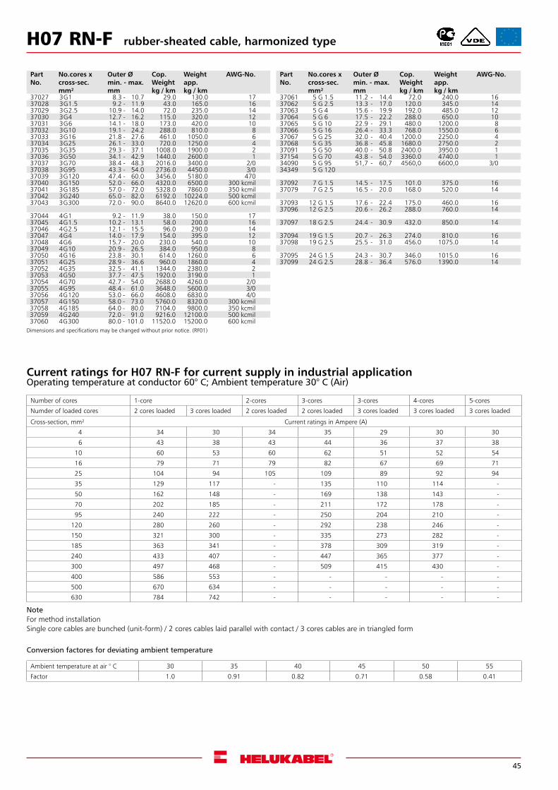
Number of cores 1-core 2-cores 3-cores 3-cores 4-cores 5-cores
Numder of loaded cores 2 cores loaded 3 cores loaded 2 cores loaded 2 cores loaded 3 cores loaded 3 cores loaded 3 cores loaded
Cross-section, mm² Current ratings in Ampere (A)
4 34 30 34 35 29 30 30
6 43 38 43 44 36 37 38
10 60 53 60 62 51 52 54
16 79 71 79 82 67 69 71
25 104 94 105 109 89 92 94
35 129 117 - 135 110 114 -
50 162 148 - 169 138 143 -
70 202 185 - 211 172 178 -
95 240 222 - 250 204 210 -
120 280 260 - 292 238 246 -
150 321 300 - 335 273 282 -
185 363 341 - 378 309 319 -
240 433 407 - 447 365 377 -
300 497 468 - 509 415 430 -
400 586 553 - - - - -
500 670 634 - - - - -
630 784 742 - - - - -
Current ratings for H07 RN-F for current supply in industrial applicationOperating temperature at conductor 60° C; Ambient temperature 30° C (Air)
NoteFor method installationSingle core cables are bunched (unit-form) / 2 cores cables laid parallel with contact / 3 cores cables are in triangled form
Conversion factores for deviating ambient temperature
Ambient temperature at air ° C 30 35 40 45 50 55
Factor 1.0 0.91 0.82 0.71 0.58 0.41
46
Technical Data• Power and control cable to DIN VDE 0276 part
603 S1, HD 603.1 and IEC 60502,7 core and above to DIN VDE 0276 part 627, HD 627 S1 and IEC 60502
•Temperature rangeflexing -5°C up to +50°Cfixed installation -40°C up to +70°C
• Permissible operating temperatureat conductor +70°C
• Permissible short circuit temperature+160°C (short circuit duration 5 sec.)
•Nominal voltage U0/U 0.6/1 kV • Test voltage 4 kV •Max. permissible tensile stress with
cable grip for Cu-conductor= 50 N/mm²
•Minimum bending radiusfor single core approx. 15x cable Øfor multi core approx. 12x cable Ø
Cable structure• Plain copper conductor, to DIN VDE 0295 cl. 1
or cl. 2 solid or stranded type, BS 6360 cl. 1 or cl. 2, IEC 60228 and HD 383
• PVC core insulation, DIV4 to HD 603.1 • Cores stranded concentrically • Colour coded to DIN VDE 0293-308, 0276 part
603 or HD 186 • Core colour for 3+½ conductor• J-type: gnye (½), bn, bk, gy•O-type: bu (½), bn, bk, gy • PVC outer jacket, DMV5 to HD 603.1 • Sheath colour black
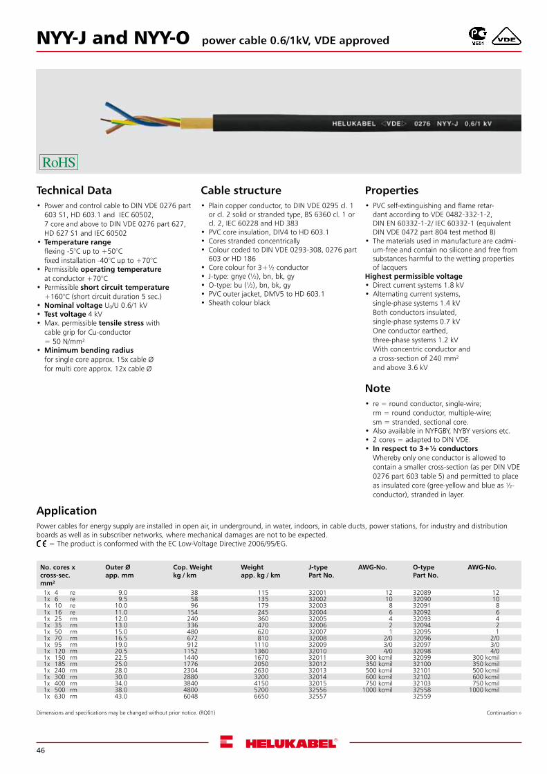
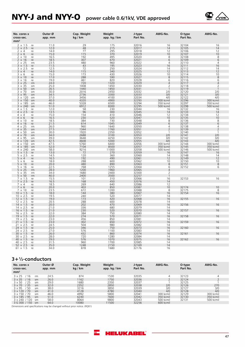
ApplicationPower cables for energy supply are installed in open air, in underground, in water, indoors, in cable ducts, power stations, for industry and distribution boards as well as in subscriber networks, where mechanical damages are not to be expected. = The product is conformed with the EC Low-Voltage Directive 2006/95/EG.
No. cores x cross-sec. mm²
Outer Øapp. mm
Cop. Weightkg / km
Weightapp. kg / km
J-type Part No.
AWG-No. O-type Part No.
AWG-No.
1x 4 re 9.0 38 115 32001 12 32089 121x 6 re 9.5 58 135 32002 10 32090 101x 10 re 10.0 96 179 32003 8 32091 81x 16 re 11.0 154 245 32004 6 32092 61x 25 rm 12.0 240 360 32005 4 32093 41x 35 rm 13.0 336 470 32006 2 32094 21x 50 rm 15.0 480 620 32007 1 32095 11x 70 rm 16.5 672 810 32008 2/0 32096 2/01x 95 rm 19.0 912 1110 32009 3/0 32097 3/01x 120 rm 20.5 1152 1360 32010 4/0 32098 4/01x 150 rm 22.5 1440 1670 32011 300 kcmil 32099 300 kcmil1x 185 rm 25.0 1776 2050 32012 350 kcmil 32100 350 kcmil1x 240 rm 28.0 2304 2630 32013 500 kcmil 32101 500 kcmil1x 300 rm 30.0 2880 3200 32014 600 kcmil 32102 600 kcmil1x 400 rm 34.0 3840 4150 32015 750 kcmil 32103 750 kcmil1x 500 rm 38.0 4800 5200 32556 1000 kcmil 32558 1000 kcmil1x 630 rm 43.0 6048 6650 32557 32559
NYY-J and NYY-O
Dimensions and specifications may be changed without prior notice. (RQ01)
power cable 0.6/1kV, VDE approved
Continuation »
Properties• PVC self-extinguishing and flame retar-
dant according to VDE 0482-332-1-2, DIN EN 60332-1-2/ IEC 60332-1 (equivalent DIN VDE 0472 part 804 test method B)
• The materials used in manufacture are cadmi-um-free and contain no silicone and free from substances harmful to the wetting properties of lacquers
Highest permissible voltage•Direct current systems 1.8 kV•Alternating current systems,
single-phase systems 1.4 kVBoth conductors insulated,single-phase systems 0.7 kVOne conductor earthed,three-phase systems 1.2 kVWith concentric conductor anda cross-section of 240 mm²and above 3.6 kV
Note• re = round conductor, single-wire;
rm = round conductor, multiple-wire;sm = stranded, sectional core.
•Also available in NYFGBY, NYBY versions etc.• 2 cores = adapted to DIN VDE.• In respect to 3+½ conductors
Whereby only one conductor is allowed to contain a smaller cross-section (as per DIN VDE 0276 part 603 table 5) and permitted to place as insulated core (gree-yellow and blue as ½-conductor), stranded in layer.
47
NYY-J and NYY-O power cable 0.6/1kV, VDE approved
No. cores x cross-sec. mm²
Outer Øapp. mm
Cop. Weightkg / km
Weightapp. kg / km
J-type Part No.
AWG-No. O-type Part No.
AWG-No.
2 x 1.5 re 11.0 29 175 32016 16 32104 162 x 2.5 re 12.0 48 215 32017 14 32105 142 x 4 re 14.0 77 295 32018 12 32106 122 x 6 re 15.0 115 370 32019 10 32107 102 x 10 re 16.5 192 495 32020 8 32108 82 x 16 re 18.5 307 670 32021 6 32109 62 x 25 rm 23.5 480 960 32022 4 32110 43 x 1.5 re 11.5 43 195 32023 16 32111 163 x 2.5 re 12.5 72 250 32024 14 32112 143 x 4 re 14.0 115 340 32025 12 32113 123 x 6 re 15.0 173 430 32026 10 32114 103 x 10 re 17.0 288 590 32027 8 32115 83 x 16 re 19.0 461 820 32028 6 32116 63 x 25 rm 24.0 720 1320 32029 4 32117 43 x 35 sm 25.0 1008 1450 32030 2 32118 23 x 50 sm 26.5 1440 1850 32031 1 32119 13 x 70 sm 30.0 2016 2450 32032 2/0 32120 2/03 x 95 sm 34.5 2736 3300 32033 3/0 32121 3/03 x 120 sm 37.0 3456 4100 32034 4/0 32122 4/03 x 150 sm 40.0 4320 4900 32293 300 kcmil 32296 300 kcmil3 x 185 sm 46.0 5328 6500 32294 350 kcmil 32297 350 kcmil3 x 240 sm 51.0 6912 8300 32295 500 kcmil 32298 500 kcmil4 x 1.5 re 12.0 58 230 32044 16 32132 164 x 2.5 re 13.5 96 300 32045 14 32133 144 x 4 re 15.0 154 410 32046 12 32134 124 x 6 re 16.5 230 520 32047 10 32135 104 x 10 re 18.5 384 730 32048 8 32136 84 x 16 re 21.5 614 1045 32049 6 32137 64 x 25 rm 26.0 960 1640 32050 4 32138 44 x 35 sm 27.5 1344 1760 32051 2 32139 24 x 50 sm 30.0 1920 2350 32052 1 32140 14 x 70 sm 34.0 2688 3100 32053 2/0 32141 2/04 x 95 sm 39.0 3648 4250 32054 3/0 32142 3/04 x 120 sm 42.5 4608 5300 32055 4/0 32143 4/04 x 150 sm 47.5 5760 6400 32056 300 kcmil 32144 300 kcmil4 x 185 sm 52.0 7104 8500 32057 350 kcmil 32145 350 kcmil4 x 240 sm 58.0 9216 11000 32058 500 kcmil 32146 500 kcmil5 x 1.5 re 13.0 72 270 32059 16 32147 165 x 2.5 re 14.5 120 360 32060 14 32148 145 x 4 re 16.5 192 490 32061 12 32149 125 x 6 re 18.0 288 600 32062 10 32150 105 x 10 re 20.0 480 890 32063 8 32151 85 x 16 re 22.5 768 1255 32064 6 32152 65 x 25 rm 28.0 1200 1960 32065 45 x 35 rm 34.0 1680 2400 32300 25 x 50 rm 40.0 2400 3500 32257 17 x 1.5 re 15.5 101 310 32066 16 32153 167 x 2.5 re 16.5 168 450 32076 147 x 4 re 18.5 269 640 32086 127 x 6 re 20.0 403 850 32087 10 32174 107 x 10 re 23.5 672 1200 32088 8 32175 8
10 x 1.5 re 18.0 144 380 32067 16 32154 1610 x 2.5 re 19.5 240 520 32077 1412 x 1.5 re 19.0 173 420 32068 16 32155 1612 x 2.5 re 20.5 288 600 32078 1414 x 1.5 re 20.0 202 470 32069 16 32156 1614 x 2.5 re 21.0 336 680 32079 1416 x 1.5 re 21.0 230 520 32070 16 32157 1616 x 2.5 re 22.0 384 750 32080 1419 x 1.5 re 22.0 274 570 32071 16 32158 1619 x 2.5 re 23.0 456 850 32081 1421 x 1.5 re 23.0 302 650 32072 16 32159 1621 x 2.5 re 24.5 504 980 32082 1424 x 1.5 re 25.0 346 750 32073 16 32160 1624 x 2.5 re 27.0 576 1100 32083 1430 x 1.5 re 26.0 432 860 32074 16 32161 1630 x 2.5 re 28.0 720 1280 32084 1440 x 1.5 re 29.0 576 1070 32075 16 32162 1640 x 2.5 re 31.5 960 1700 32085 1452 x 2.5 re 35.0 1248 2150 32169 1461 x 1.5 re 34.0 878 1680 32176 16
No. cores x cross-sec. mm²
Outer Øapp. mm
Cop. Weightkg / km
Weightapp. kg / km
J-type Part No.
AWG-No. O-type Part No.
AWG-No.
3 x 25 / 16 rm 24.5 874 1530 32035 4 32123 43 x 35 / 16 sm 26.0 1162 1750 32036 2 32124 23 x 50 / 25 sm 29.0 1680 2350 32037 1 32125 13 x 70 / 35 sm 32.0 2352 2850 32038 2/0 32126 2703 x 95 / 50 sm 38.0 3216 3850 32039 3/0 32127 3/03 x 120 / 70 sm 41.0 4128 4780 32040 4/0 32128 4/03 x 150 / 70 sm 46.0 4992 5800 32041 300 kcmil 32129 300 kcmil3 x 185 / 95 sm 51.0 6240 7600 32042 350 kcmil 32130 350 kcmil3 x 240 / 120 sm 58.0 8064 9800 32043 500 kcmil 32131 500 kcmil3 G 300 / 150 sm 64.0 10080 11500 32256 600 kcmil
3+½-conductors
Dimensions and specifications may be changed without prior notice. (RQ01)
48
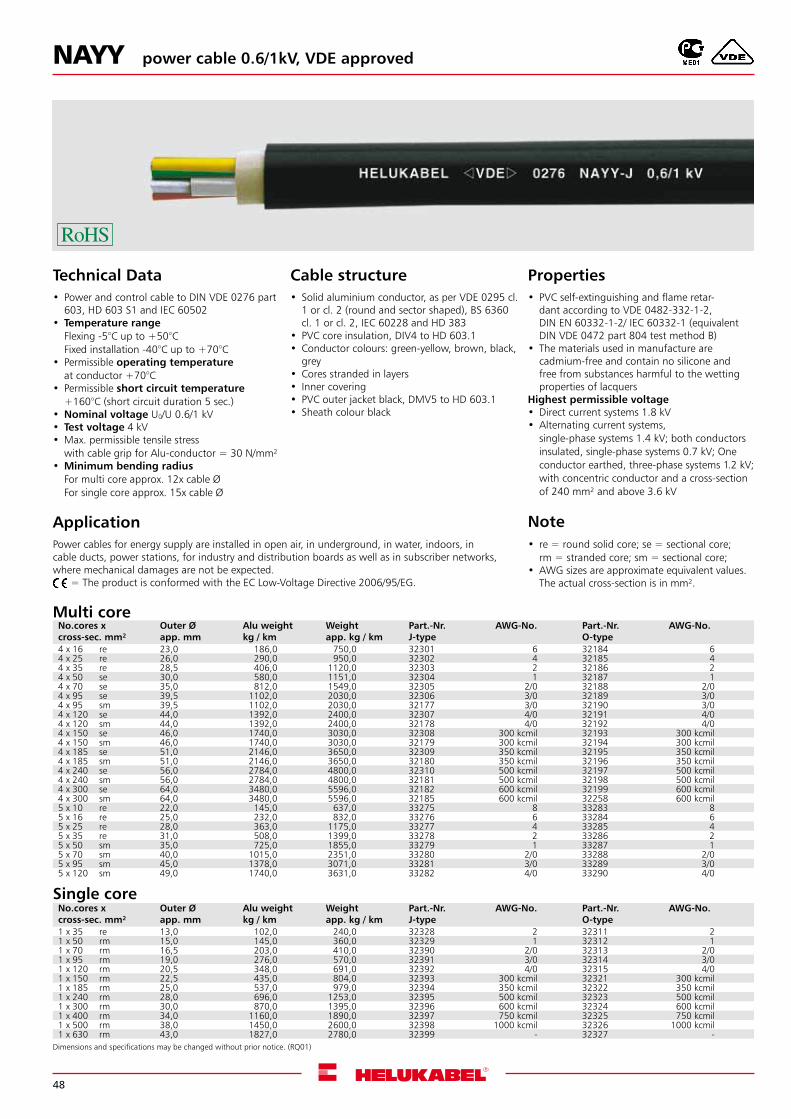
NAYY power cable 0.6/1kV, VDE approved
Technical Data• Power and control cable to DIN VDE 0276 part
603, HD 603 S1 and IEC 60502 • Temperature range
Flexing -5°C up to +50°CFixed installation -40°C up to +70°C
• Permissible operating temperatureat conductor +70°C
• Permissible short circuit temperature+160°C (short circuit duration 5 sec.)
•Nominal voltage U0/U 0.6/1 kV • Test voltage 4 kV •Max. permissible tensile stress
with cable grip for Alu-conductor = 30 N/mm² •Minimum bending radius
For multi core approx. 12x cable Ø For single core approx. 15x cable Ø
Cable structure• Solid aluminium conductor, as per VDE 0295 cl.
1 or cl. 2 (round and sector shaped), BS 6360 cl. 1 or cl. 2, IEC 60228 and HD 383
• PVC core insulation, DIV4 to HD 603.1 • Conductor colours: green-yellow, brown, black,
grey • Cores stranded in layers • Inner covering • PVC outer jacket black, DMV5 to HD 603.1 • Sheath colour black
Properties• PVC self-extinguishing and flame retar-
dant according to VDE 0482-332-1-2, DIN EN 60332-1-2/ IEC 60332-1 (equivalent DIN VDE 0472 part 804 test method B)
• The materials used in manufacture are cadmium-free and contain no silicone and free from substances harmful to the wetting properties of lacquers
Highest permissible voltage•Direct current systems 1.8 kV•Alternating current systems,
single-phase systems 1.4 kV; both conductors insulated, single-phase systems 0.7 kV; One conductor earthed, three-phase systems 1.2 kV; with concentric conductor and a cross-section of 240 mm² and above 3.6 kV
Note• re = round solid core; se = sectional core;
rm = stranded core; sm = sectional core;•AWG sizes are approximate equivalent values.
The actual cross-section is in mm².
ApplicationPower cables for energy supply are installed in open air, in underground, in water, indoors, in cable ducts, power stations, for industry and distribution boards as well as in subscriber networks, where mechanical damages are not be expected. = The product is conformed with the EC Low-Voltage Directive 2006/95/EG.
Dimensions and specifications may be changed without prior notice. (RQ01)
No.cores x cross-sec. mm²
Outer Øapp. mm
Alu weightkg / km
Weightapp. kg / km
Part.-Nr.J-type
AWG-No. Part.-Nr.O-type
AWG-No.
4 x 16 re 23,0 186,0 750,0 32301 6 32184 64 x 25 re 26,0 290,0 950,0 32302 4 32185 44 x 35 re 28,5 406,0 1120,0 32303 2 32186 24 x 50 se 30,0 580,0 1151,0 32304 1 32187 14 x 70 se 35,0 812,0 1549,0 32305 2/0 32188 2/04 x 95 se 39,5 1102,0 2030,0 32306 3/0 32189 3/04 x 95 sm 39,5 1102,0 2030,0 32177 3/0 32190 3/04 x 120 se 44,0 1392,0 2400,0 32307 4/0 32191 4/04 x 120 sm 44,0 1392,0 2400,0 32178 4/0 32192 4/04 x 150 se 46,0 1740,0 3030,0 32308 300 kcmil 32193 300 kcmil4 x 150 sm 46,0 1740,0 3030,0 32179 300 kcmil 32194 300 kcmil4 x 185 se 51,0 2146,0 3650,0 32309 350 kcmil 32195 350 kcmil4 x 185 sm 51,0 2146,0 3650,0 32180 350 kcmil 32196 350 kcmil4 x 240 se 56,0 2784,0 4800,0 32310 500 kcmil 32197 500 kcmil4 x 240 sm 56,0 2784,0 4800,0 32181 500 kcmil 32198 500 kcmil4 x 300 se 64,0 3480,0 5596,0 32182 600 kcmil 32199 600 kcmil4 x 300 sm 64,0 3480,0 5596,0 32185 600 kcmil 32258 600 kcmil5 x 10 re 22,0 145,0 637,0 33275 8 33283 85 x 16 re 25,0 232,0 832,0 33276 6 33284 65 x 25 re 28,0 363,0 1175,0 33277 4 33285 45 x 35 re 31,0 508,0 1399,0 33278 2 33286 25 x 50 sm 35,0 725,0 1855,0 33279 1 33287 15 x 70 sm 40,0 1015,0 2351,0 33280 2/0 33288 2/05 x 95 sm 45,0 1378,0 3071,0 33281 3/0 33289 3/05 x 120 sm 49,0 1740,0 3631,0 33282 4/0 33290 4/0
No.cores x cross-sec. mm²
Outer Øapp. mm
Alu weightkg / km
Weightapp. kg / km
Part.-Nr.J-type
AWG-No. Part.-Nr.O-type
AWG-No.
1 x 35 re 13,0 102,0 240,0 32328 2 32311 21 x 50 rm 15,0 145,0 360,0 32329 1 32312 11 x 70 rm 16,5 203,0 410,0 32390 2/0 32313 2/01 x 95 rm 19,0 276,0 570,0 32391 3/0 32314 3/01 x 120 rm 20,5 348,0 691,0 32392 4/0 32315 4/01 x 150 rm 22,5 435,0 804,0 32393 300 kcmil 32321 300 kcmil1 x 185 rm 25,0 537,0 979,0 32394 350 kcmil 32322 350 kcmil1 x 240 rm 28,0 696,0 1253,0 32395 500 kcmil 32323 500 kcmil1 x 300 rm 30,0 870,0 1395,0 32396 600 kcmil 32324 600 kcmil1 x 400 rm 34,0 1160,0 1890,0 32397 750 kcmil 32325 750 kcmil1 x 500 rm 38,0 1450,0 2600,0 32398 1000 kcmil 32326 1000 kcmil1 x 630 rm 43,0 1827,0 2780,0 32399 - 32327 -
Single core
Multi core
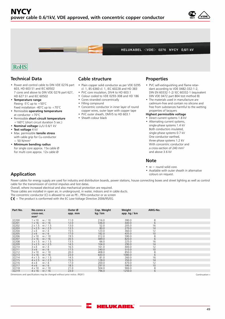
49
power cable 0.6/1kV, VDE approved, with concentric copper conductorNYCY
Technical Data• Power and control cable to DIN VDE 0276 part
603, HD 603 S1 and IEC 605027 cores and above to DIN VDE 0276 part 627, HD 627 S1 and IEC 60502
• Temperature rangeFlexing -5°C up to +50°CFixed installation -40°C up to +70°C
• Permissible operating temperatureat conductor +70°C
• Permissible short circuit temperature+160°C (short circuit duration 5 sec.)
•Nominal voltage U0/U 0.6/1 kV • Test voltage 4 kV •Max. permissible tensile stress
with cable grip for Cu-conductor= 50 N/mm²
•Minimum bending radiusFor single core approx. 15x cable ØFor multi core approx. 12x cable Ø
ApplicationPower cables for energy supply are used for industry and distribution boards, power stations, house connecting boxes and street lighting as well as control cable for the transmission of control impulses and test datas.Overall, where increased electrical and also mechanical protection are required.Those cables are installed in open air, in underground, in water, indoors and in cable ducts.The concentric conductor (C) is allowed to use as PE-, PEN-conductor or as screen
= The product is conformed with the EC Low-Voltage Directive 2006/95/EG.
Cable structure• Plain copper solid conductor as per VDE 0295
cl. 1, BS 6360 cl. 1, IEC 60228 and HD 383 • PVC core insulation, DIV4 to HD 603.1 • Colour coded to VDE 0293-308 and HD 186 • Cores stranded concentrically • Filling compound • Concentric conductor in inner layer of round
copper wires, outer layer with copper tape • PVC outer sheath, DMV5 to HD 603.1 • Sheath colour black
Properties• PVC self-extinguishing and flame retar-
dant according to VDE 0482-332-1-2, DIN EN 60332-1-2/ IEC 60332-1 (equivalent DIN VDE 0472 part 804 test method B)
• The materials used in manufacture are cadmium-free and contain no silicone and free from substances harmful to the wetting properties of lacquers
Highest permissible voltage•Direct current systems 1.8 kV•Alternating current systems,
single-phase systems 1.4 kVBoth conductors insulated,single-phase systems 0.7 kVOne conductor earthed,three-phase systems 1.2 kVWith concentric conductor anda cross-section of 240 mm²and above 3.6 kV
Note• re = round solid core.•Available with outer sheath in alternative
colours on request.
Part No. No.cores x cross-sec.mm²
Outer Øapp. mm
Cop. Weightkg / km
Weightapp. kg / km
AWG-No.
32200 1 x 10 re / 10 11.0 216.0 280.0 832201 1 x 16 re / 16 12.0 336.0 440.0 632202 2 x 1.5 re / 1.5 13.0 52.0 205.0 1632203 2 x 2.5 re / 2.5 13.5 80.0 270.0 1432204 2 x 4 re / 4 15.5 123.0 360.0 1232205 2 x 6 re / 6 17.0 182.0 435.0 1032206 2 x 10 re / 10 19.5 312.0 590.0 832207 2 x 16 re / 16 20.5 489.0 820.0 632208 3 x 1.5 re / 1.5 13.5 66.0 225.0 1632209 3 x 2.5 re / 2.5 14.5 104.0 290.0 1432210 3 x 4 re / 4 16.5 161.0 400.0 1232211 3 x 6 re / 6 17.5 240.0 510.0 1032212 3 x 10 re / 10 20.0 408.0 850.0 832213 3 x 16 re / 16 23.0 643.0 1080.0 632214 4 x 1.5 re / 1.5 14.5 81.0 260.0 1632215 4 x 2.5 re / 2.5 15.5 128.0 350.0 1432216 4 x 4 re / 4 17.0 200.0 470.0 1232217 4 x 6 re / 6 18.5 297.0 590.0 1032218 4 x 10 re / 10 21.0 504.0 900.0 832219 4 x 16 re / 16 23.0 796.0 1250.0 6
Dimensions and specifications may be changed without prior notice. (RQ01) Continuation »
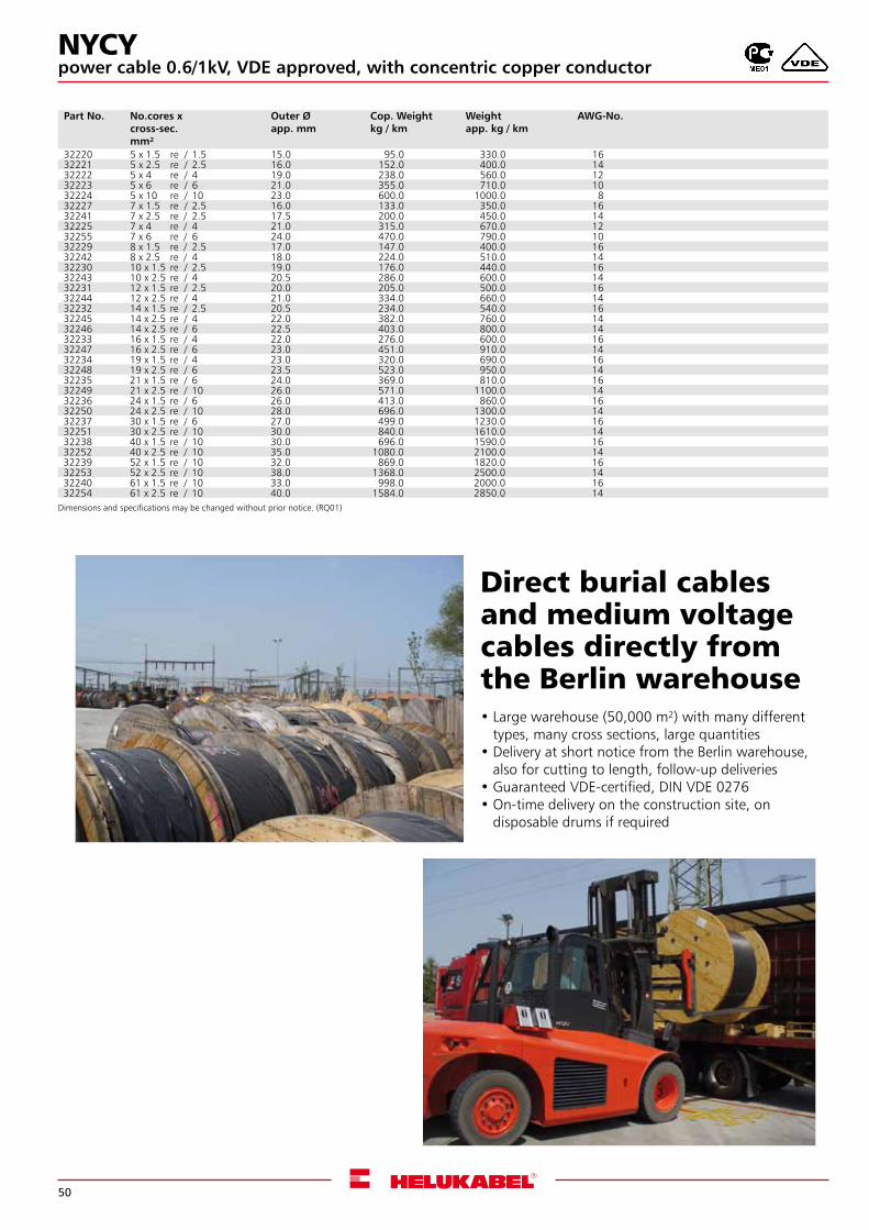
50
power cable 0.6/1kV, VDE approved, with concentric copper conductorNYCY
Part No. No.cores x cross-sec.mm²
Outer Øapp. mm
Cop. Weightkg / km
Weightapp. kg / km
AWG-No.
32220 5 x 1.5 re / 1.5 15.0 95.0 330.0 1632221 5 x 2.5 re / 2.5 16.0 152.0 400.0 1432222 5 x 4 re / 4 19.0 238.0 560.0 1232223 5 x 6 re / 6 21.0 355.0 710.0 1032224 5 x 10 re / 10 23.0 600.0 1000.0 832227 7 x 1.5 re / 2.5 16.0 133.0 350.0 1632241 7 x 2.5 re / 2.5 17.5 200.0 450.0 1432225 7 x 4 re / 4 21.0 315.0 670.0 1232255 7 x 6 re / 6 24.0 470.0 790.0 1032229 8 x 1.5 re / 2.5 17.0 147.0 400.0 1632242 8 x 2.5 re / 4 18.0 224.0 510.0 1432230 10 x 1.5 re / 2.5 19.0 176.0 440.0 1632243 10 x 2.5 re / 4 20.5 286.0 600.0 1432231 12 x 1.5 re / 2.5 20.0 205.0 500.0 1632244 12 x 2.5 re / 4 21.0 334.0 660.0 1432232 14 x 1.5 re / 2.5 20.5 234.0 540.0 1632245 14 x 2.5 re / 4 22.0 382.0 760.0 1432246 14 x 2.5 re / 6 22.5 403.0 800.0 1432233 16 x 1.5 re / 4 22.0 276.0 600.0 1632247 16 x 2.5 re / 6 23.0 451.0 910.0 1432234 19 x 1.5 re / 4 23.0 320.0 690.0 1632248 19 x 2.5 re / 6 23.5 523.0 950.0 1432235 21 x 1.5 re / 6 24.0 369.0 810.0 1632249 21 x 2.5 re / 10 26.0 571.0 1100.0 1432236 24 x 1.5 re / 6 26.0 413.0 860.0 1632250 24 x 2.5 re / 10 28.0 696.0 1300.0 1432237 30 x 1.5 re / 6 27.0 499.0 1230.0 1632251 30 x 2.5 re / 10 30.0 840.0 1610.0 1432238 40 x 1.5 re / 10 30.0 696.0 1590.0 1632252 40 x 2.5 re / 10 35.0 1080.0 2100.0 1432239 52 x 1.5 re / 10 32.0 869.0 1820.0 1632253 52 x 2.5 re / 10 38.0 1368.0 2500.0 1432240 61 x 1.5 re / 10 33.0 998.0 2000.0 1632254 61 x 2.5 re / 10 40.0 1584.0 2850.0 14
Dimensions and specifications may be changed without prior notice. (RQ01)
Direct burial cables and medium voltage cables directly from the Berlin warehouse•Large warehouse (50,000 m²) with many different
types, many cross sections, large quantities•Delivery at short notice from the Berlin warehouse,
also for cutting to length, follow-up deliveries•Guaranteed VDE-certified, DIN VDE 0276•On-time delivery on the construction site, on
disposable drums if required
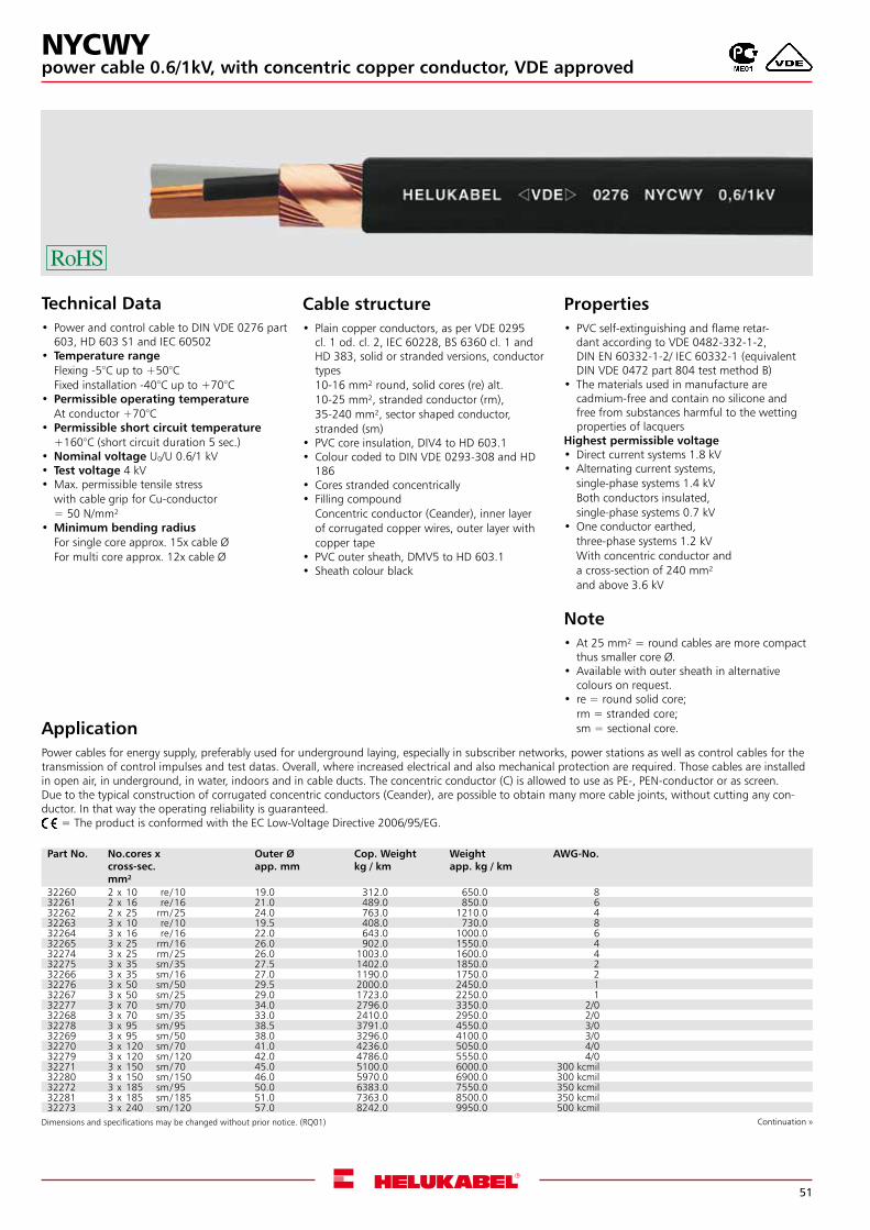
51
Technical Data• Power and control cable to DIN VDE 0276 part
603, HD 603 S1 and IEC 60502 • Temperature range
Flexing -5°C up to +50°CFixed installation -40°C up to +70°C
• Permissible operating temperatureAt conductor +70°C
• Permissible short circuit temperature+160°C (short circuit duration 5 sec.)
•Nominal voltage U0/U 0.6/1 kV • Test voltage 4 kV •Max. permissible tensile stress
with cable grip for Cu-conductor= 50 N/mm²
•Minimum bending radiusFor single core approx. 15x cable ØFor multi core approx. 12x cable Ø
ApplicationPower cables for energy supply, preferably used for underground laying, especially in subscriber networks, power stations as well as control cables for the transmission of control impulses and test datas. Overall, where increased electrical and also mechanical protection are required. Those cables are installed in open air, in underground, in water, indoors and in cable ducts. The concentric conductor (C) is allowed to use as PE-, PEN-conductor or as screen.Due to the typical construction of corrugated concentric conductors (Ceander), are possible to obtain many more cable joints, without cutting any con-ductor. In that way the operating reliability is guaranteed. = The product is conformed with the EC Low-Voltage Directive 2006/95/EG.
Cable structure• Plain copper conductors, as per VDE 0295
cl. 1 od. cl. 2, IEC 60228, BS 6360 cl. 1 and HD 383, solid or stranded versions, conductor types10-16 mm² round, solid cores (re) alt.10-25 mm², stranded conductor (rm), 35-240 mm², sector shaped conductor, stranded (sm)
• PVC core insulation, DIV4 to HD 603.1 • Colour coded to DIN VDE 0293-308 and HD
186 • Cores stranded concentrically • Filling compound
Concentric conductor (Ceander), inner layer of corrugated copper wires, outer layer with copper tape
• PVC outer sheath, DMV5 to HD 603.1 • Sheath colour black
Properties• PVC self-extinguishing and flame retar-
dant according to VDE 0482-332-1-2, DIN EN 60332-1-2/ IEC 60332-1 (equivalent DIN VDE 0472 part 804 test method B)
• The materials used in manufacture are cadmium-free and contain no silicone and free from substances harmful to the wetting properties of lacquers
Highest permissible voltage•Direct current systems 1.8 kV•Alternating current systems,
single-phase systems 1.4 kVBoth conductors insulated,single-phase systems 0.7 kV
•One conductor earthed,three-phase systems 1.2 kVWith concentric conductor anda cross-section of 240 mm²and above 3.6 kV
Note•At 25 mm² = round cables are more compact
thus smaller core Ø.•Available with outer sheath in alternative
colours on request.• re = round solid core;
rm = stranded core;sm = sectional core.
Dimensions and specifications may be changed without prior notice. (RQ01) Continuation »
Part No. No.cores x cross-sec.mm²
Outer Øapp. mm
Cop. Weightkg / km
Weightapp. kg / km
AWG-No.
32260 2 x 10 re /10 19.0 312.0 650.0 832261 2 x 16 re /16 21.0 489.0 850.0 632262 2 x 25 rm/25 24.0 763.0 1210.0 432263 3 x 10 re /10 19.5 408.0 730.0 832264 3 x 16 re /16 22.0 643.0 1000.0 632265 3 x 25 rm/16 26.0 902.0 1550.0 432274 3 x 25 rm/25 26.0 1003.0 1600.0 432275 3 x 35 sm/35 27.5 1402.0 1850.0 232266 3 x 35 sm/16 27.0 1190.0 1750.0 232276 3 x 50 sm/50 29.5 2000.0 2450.0 132267 3 x 50 sm/25 29.0 1723.0 2250.0 132277 3 x 70 sm/70 34.0 2796.0 3350.0 2/032268 3 x 70 sm/35 33.0 2410.0 2950.0 2/032278 3 x 95 sm/95 38.5 3791.0 4550.0 3/032269 3 x 95 sm/50 38.0 3296.0 4100.0 3/032270 3 x 120 sm/70 41.0 4236.0 5050.0 4/032279 3 x 120 sm/120 42.0 4786.0 5550.0 4/032271 3 x 150 sm/70 45.0 5100.0 6000.0 300 kcmil32280 3 x 150 sm/150 46.0 5970.0 6900.0 300 kcmil32272 3 x 185 sm/95 50.0 6383.0 7550.0 350 kcmil32281 3 x 185 sm/185 51.0 7363.0 8500.0 350 kcmil32273 3 x 240 sm/120 57.0 8242.0 9950.0 500 kcmil
NYCWYpower cable 0.6/1kV, with concentric copper conductor, VDE approved
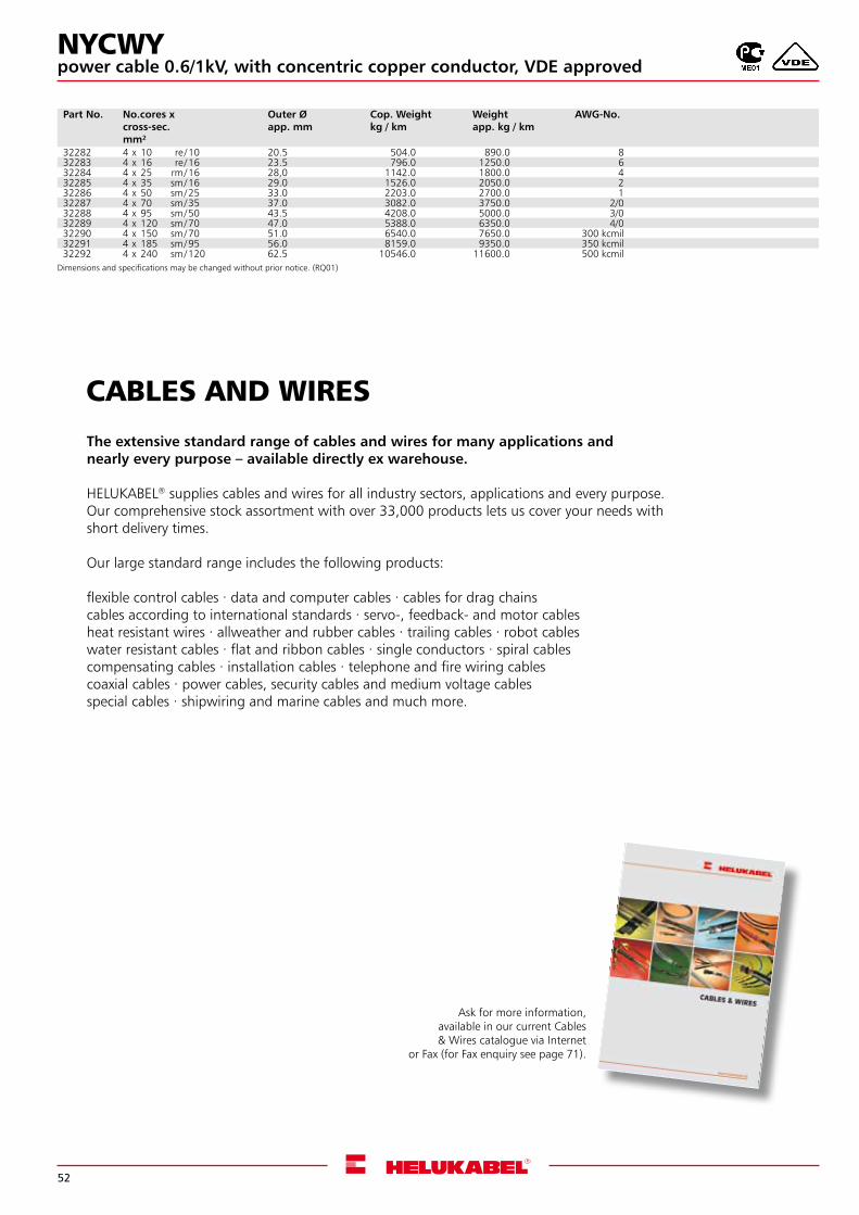
52
CABLES AND WIRES
The extensive standard range of cables and wires for many applications andnearly every purpose – available directly ex warehouse.
HELUKABEL® supplies cables and wires for all industry sectors, applications and every purpose.Our comprehensive stock assortment with over 33,000 products lets us cover your needs with short delivery times.
Our large standard range includes the following products:
flexible control cables . data and computer cables . cables for drag chainscables according to international standards . servo-, feedback- and motor cablesheat resistant wires . allweather and rubber cables . trailing cables . robot cableswater resistant cables . flat and ribbon cables . single conductors . spiral cables compensating cables . installation cables . telephone and fire wiring cablescoaxial cables . power cables, security cables and medium voltage cables special cables . shipwiring and marine cables and much more.
Ask for more information,available in our current Cables & Wires catalogue via Internet
or Fax (for Fax enquiry see page 71).
Part No. No.cores x cross-sec.mm²
Outer Øapp. mm
Cop. Weightkg / km
Weightapp. kg / km
AWG-No.
32282 4 x 10 re /10 20.5 504.0 890.0 832283 4 x 16 re /16 23.5 796.0 1250.0 632284 4 x 25 rm/16 28,0 1142.0 1800.0 432285 4 x 35 sm/16 29.0 1526.0 2050.0 232286 4 x 50 sm/25 33.0 2203.0 2700.0 132287 4 x 70 sm/35 37.0 3082.0 3750.0 2/032288 4 x 95 sm/50 43.5 4208.0 5000.0 3/032289 4 x 120 sm/70 47.0 5388.0 6350.0 4/032290 4 x 150 sm/70 51.0 6540.0 7650.0 300 kcmil32291 4 x 185 sm/95 56.0 8159.0 9350.0 350 kcmil32292 4 x 240 sm/120 62.5 10546.0 11600.0 500 kcmil
Dimensions and specifications may be changed without prior notice. (RQ01)
NYCWYpower cable 0.6/1kV, with concentric copper conductor, VDE approved
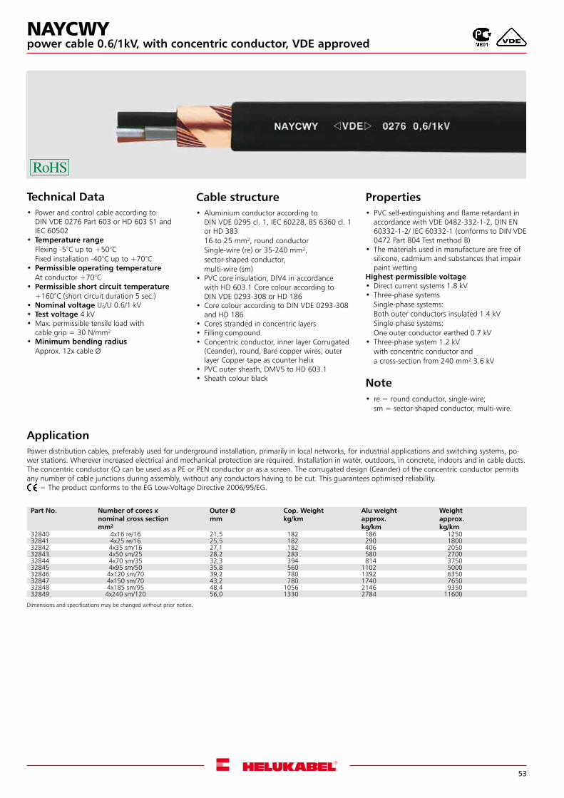
53
Dimensions and specifications may be changed without prior notice.
Technical Data• Power and control cable according to
DIN VDE 0276 Part 603 or HD 603 S1 and IEC 60502
• Temperature rangeFlexing -5°C up to +50°CFixed installation -40°C up to +70°C
• Permissible operating temperatureAt conductor +70°C
• Permissible short circuit temperature+160°C (short circuit duration 5 sec.)
•Nominal voltage U0/U 0.6/1 kV • Test voltage 4 kV •Max. permissible tensile load with
cable grip = 30 N/mm²•Minimum bending radius
Approx. 12x cable Ø
ApplicationPower distribution cables, preferably used for underground installation, primarily in local networks, for industrial applications and switching systems, po-wer stations. Wherever increased electrical and mechanical protection are required. Installation in water, outdoors, in concrete, indoors and in cable ducts. The concentric conductor (C) can be used as a PE or PEN conductor or as a screen. The corrugated design (Ceander) of the concentric conductor permits any number of cable junctions during assembly, without any conductors having to be cut. This guarantees optimised reliability. = The product conforms to the EG Low-Voltage Directive 2006/95/EG.
Cable structure•Aluminium conductor according to
DIN VDE 0295 cl. 1, IEC 60228, BS 6360 cl. 1 or HD 38316 to 25 mm², round conductor Single-wire (re) or 35-240 mm², sector-shaped conductor, multi-wire (sm)
• PVC core insulation, DIV4 in accordance with HD 603.1 Core colour according to DIN VDE 0293-308 or HD 186
• Core colour according to DIN VDE 0293-308 and HD 186
• Cores stranded in concentric layers • Filling compound• Concentric conductor, inner layer Corrugated
(Ceander), round, Bare copper wires, outer layer Copper tape as counter helix
• PVC outer sheath, DMV5 to HD 603.1 • Sheath colour black
Properties• PVC self-extinguishing and flame retardant in
accordance with VDE 0482-332-1-2, DIN EN 60332-1-2/ IEC 60332-1 (conforms to DIN VDE 0472 Part 804 Test method B)
• The materials used in manufacture are free of silicone, cadmium and substances that impair paint wetting
Highest permissible voltage•Direct current systems 1.8 kV • Three-phase systems
Single-phase systems: Both outer conductors insulated 1.4 kVSingle-phase systems: One outer conductor earthed 0.7 kV
• Three-phase system 1.2 kVwith concentric conductor anda cross-section from 240 mm² 3.6 kV
Note• re = round conductor, single-wire;
sm = sector-shaped conductor, multi-wire.
NAYCWYpower cable 0.6/1kV, with concentric conductor, VDE approved
Part No. Number of cores x nominal cross section mm²
Outer Ø mm
Cop. Weight kg/km
Alu weightapprox. kg/km
Weightapprox. kg/km
32840 4x16 re/16 21,5 182 186 1250 32841 4x25 re/16 25,5 182 290 180032842 4x35 sm/16 27,1 182 406 205032843 4x50 sm/25 28,2 283 580 270032844 4x70 sm/35 32,3 394 814 375032845 4x95 sm/50 35,8 560 1102 500032846 4x120 sm/70 39,2 780 1392 635032847 4x150 sm/70 43,2 780 1740 765032848 4x185 sm/95 48,4 1056 2146 935032849 4x240 sm/120 56,0 1330 2784 11600
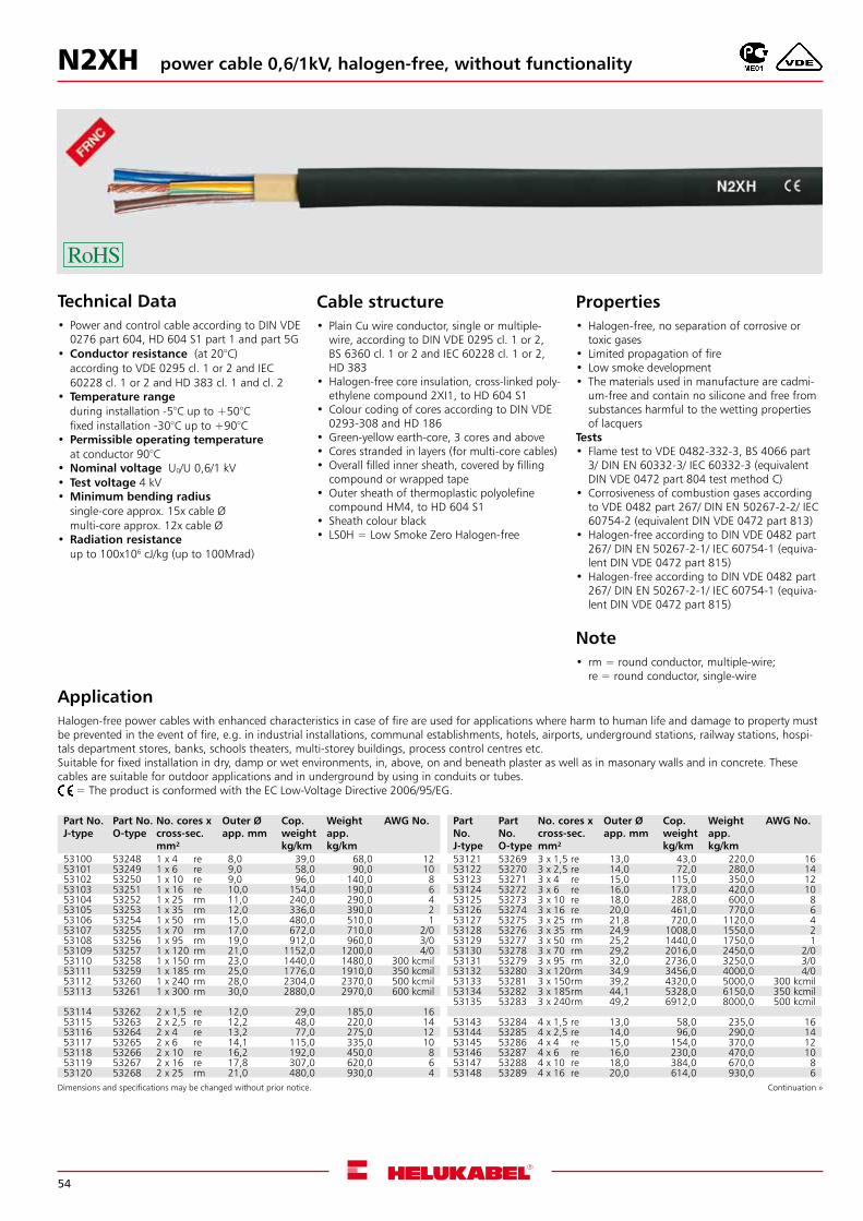
54
N2XH power cable 0,6/1kV, halogen-free, without functionality
Technical Data• Power and control cable according to DIN VDE
0276 part 604, HD 604 S1 part 1 and part 5G •Conductor resistance (at 20°C)
according to VDE 0295 cl. 1 or 2 and IEC 60228 cl. 1 or 2 and HD 383 cl. 1 and cl. 2
• Temperature rangeduring installation -5°C up to +50°Cfixed installation -30°C up to +90°C
• Permissible operating temperatureat conductor 90°C
•Nominal voltage U0/U 0,6/1 kV • Test voltage 4 kV •Minimum bending radius
single-core approx. 15x cable Ømulti-core approx. 12x cable Ø
•Radiation resistanceup to 100x106 cJ/kg (up to 100Mrad)
ApplicationHalogen-free power cables with enhanced characteristics in case of fire are used for applications where harm to human life and damage to property must be prevented in the event of fire, e.g. in industrial installations, communal establishments, hotels, airports, underground stations, railway stations, hospi-tals department stores, banks, schools theaters, multi-storey buildings, process control centres etc.Suitable for fixed installation in dry, damp or wet environments, in, above, on and beneath plaster as well as in masonary walls and in concrete. These cables are suitable for outdoor applications and in underground by using in conduits or tubes. = The product is conformed with the EC Low-Voltage Directive 2006/95/EG.
Cable structure• Plain Cu wire conductor, single or multiple-
wire, according to DIN VDE 0295 cl. 1 or 2, BS 6360 cl. 1 or 2 and IEC 60228 cl. 1 or 2, HD 383
•Halogen-free core insulation, cross-linked poly-ethylene compound 2XI1, to HD 604 S1
• Colour coding of cores according to DIN VDE 0293-308 and HD 186
•Green-yellow earth-core, 3 cores and above• Cores stranded in layers (for multi-core cables)•Overall filled inner sheath, covered by filling
compound or wrapped tape•Outer sheath of thermoplastic polyolefine
compound HM4, to HD 604 S1• Sheath colour black• LS0H = Low Smoke Zero Halogen-free
Properties•Halogen-free, no separation of corrosive or
toxic gases• Limited propagation of fire• Low smoke development • The materials used in manufacture are cadmi-
um-free and contain no silicone and free from substances harmful to the wetting properties of lacquers
Tests• Flame test to VDE 0482-332-3, BS 4066 part
3/ DIN EN 60332-3/ IEC 60332-3 (equivalent DIN VDE 0472 part 804 test method C)
• Corrosiveness of combustion gases according to VDE 0482 part 267/ DIN EN 50267-2-2/ IEC 60754-2 (equivalent DIN VDE 0472 part 813)
•Halogen-free according to DIN VDE 0482 part 267/ DIN EN 50267-2-1/ IEC 60754-1 (equiva-lent DIN VDE 0472 part 815)
•Halogen-free according to DIN VDE 0482 part 267/ DIN EN 50267-2-1/ IEC 60754-1 (equiva-lent DIN VDE 0472 part 815)
Note• rm = round conductor, multiple-wire;
re = round conductor, single-wire
Dimensions and specifications may be changed without prior notice. Continuation »
Part No.J-type
Part No.O-type
No. cores x cross-sec. mm²
Outer Ø app. mm
Cop. weight kg/km
Weightapp. kg/km
AWG No.
53100 53248 1 x 4 re 8,0 39,0 68,0 1253101 53249 1 x 6 re 9,0 58,0 90,0 1053102 53250 1 x 10 re 9,0 96,0 140,0 853103 53251 1 x 16 re 10,0 154,0 190,0 653104 53252 1 x 25 rm 11,0 240,0 290,0 453105 53253 1 x 35 rm 12,0 336,0 390,0 253106 53254 1 x 50 rm 15,0 480,0 510,0 153107 53255 1 x 70 rm 17,0 672,0 710,0 2/053108 53256 1 x 95 rm 19,0 912,0 960,0 3/053109 53257 1 x 120 rm 21,0 1152,0 1200,0 4/053110 53258 1 x 150 rm 23,0 1440,0 1480,0 300 kcmil53111 53259 1 x 185 rm 25,0 1776,0 1910,0 350 kcmil53112 53260 1 x 240 rm 28,0 2304,0 2370,0 500 kcmil53113 53261 1 x 300 rm 30,0 2880,0 2970,0 600 kcmil
53114 53262 2 x 1,5 re 12,0 29,0 185,0 1653115 53263 2 x 2,5 re 12,2 48,0 220,0 1453116 53264 2 x 4 re 13,2 77,0 275,0 1253117 53265 2 x 6 re 14,1 115,0 335,0 1053118 53266 2 x 10 re 16,2 192,0 450,0 853119 53267 2 x 16 re 17,8 307,0 620,0 653120 53268 2 x 25 rm 21,0 480,0 930,0 4
Part No.J-type
Part No.O-type
No. cores x cross-sec. mm²
Outer Ø app. mm
Cop. weight kg/km
Weightapp. kg/km
AWG No.
53121 53269 3 x 1,5 re 13,0 43,0 220,0 1653122 53270 3 x 2,5 re 14,0 72,0 280,0 1453123 53271 3 x 4 re 15,0 115,0 350,0 1253124 53272 3 x 6 re 16,0 173,0 420,0 1053125 53273 3 x 10 re 18,0 288,0 600,0 853126 53274 3 x 16 re 20,0 461,0 770,0 653127 53275 3 x 25 rm 21,8 720,0 1120,0 453128 53276 3 x 35 rm 24,9 1008,0 1550,0 253129 53277 3 x 50 rm 25,2 1440,0 1750,0 153130 53278 3 x 70 rm 29,2 2016,0 2450,0 2/053131 53279 3 x 95 rm 32,0 2736,0 3250,0 3/053132 53280 3 x 120rm 34,9 3456,0 4000,0 4/053133 53281 3 x 150rm 39,2 4320,0 5000,0 300 kcmil53134 53282 3 x 185rm 44,1 5328,0 6150,0 350 kcmil53135 53283 3 x 240rm 49,2 6912,0 8000,0 500 kcmil
53143 53284 4 x 1,5 re 13,0 58,0 235,0 1653144 53285 4 x 2,5 re 14,0 96,0 290,0 1453145 53286 4 x 4 re 15,0 154,0 370,0 1253146 53287 4 x 6 re 16,0 230,0 470,0 1053147 53288 4 x 10 re 18,0 384,0 670,0 853148 53289 4 x 16 re 20,0 614,0 930,0 6
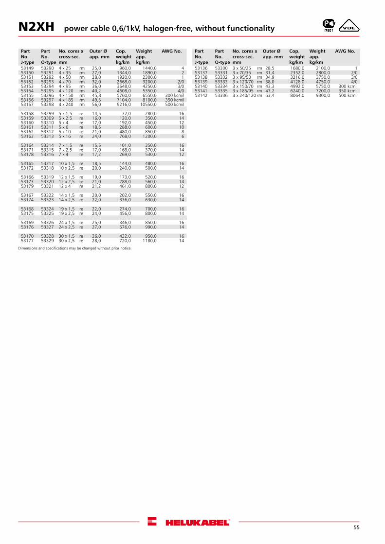
55
N2XH
Part No.J-type
Part No.O-type
No. cores x cross-sec. mm
Outer Ø app. mm
Cop. weight kg/km
Weightapp. kg/km
AWG No.
53149 53290 4 x 25 rm 25,0 960,0 1440,0 453150 53291 4 x 35 rm 27,0 1344,0 1890,0 253151 53292 4 x 50 rm 28,0 1920,0 2300,0 153152 53293 4 x 70 rm 32,0 2668,0 3200,0 2/053153 53294 4 x 95 rm 36,0 3648,0 4250,0 3/053154 53295 4 x 120 rm 40,2 4608,0 5350,0 4/053155 53296 4 x 150 rm 45,8 5760,0 6550,0 300 kcmil53156 53297 4 x 185 rm 49,5 7104,0 8100,0 350 kcmil 53157 53298 4 x 240 rm 56,0 9216,0 10550,0 500 kcmil 53158 53299 5 x 1,5 re 14,5 72,0 280,0 1653159 53309 5 x 2,5 re 16,0 120,0 350,0 1453160 53310 5 x 4 re 17,0 192,0 450,0 1253161 53311 5 x 6 re 18,5 288,0 600,0 1053162 53312 5 x 10 re 21,0 480,0 850,0 853163 53313 5 x 16 re 24,0 768,0 1200,0 6 53164 53314 7 x 1,5 re 15,5 101,0 350,0 1653171 53315 7 x 2,5 re 17,0 168,0 370,0 1453178 53316 7 x 4 re 17,2 269,0 530,0 12 53165 53317 10 x 1,5 re 18,5 144,0 480,0 1653172 53318 10 x 2,5 re 20,0 240,0 500,0 14 53166 53319 12 x 1,5 re 19,0 173,0 520,0 1653173 53320 12 x 2,5 re 21,0 288,0 560,0 1453179 53321 12 x 4 re 21,2 461,0 800,0 12 53167 53322 14 x 1,5 re 20,0 202,0 550,0 1653174 53323 14 x 2,5 re 22,0 336,0 630,0 14 53168 53324 19 x 1,5 re 22,0 274,0 700,0 1653175 53325 19 x 2,5 re 24,0 456,0 800,0 14 53169 53326 24 x 1,5 re 25,0 346,0 850,0 1653176 53327 24 x 2,5 re 27,0 576,0 990,0 14 53170 53328 30 x 1,5 re 26,0 432,0 950,0 1653177 53329 30 x 2,5 re 28,0 720,0 1180,0 14
Part No.J-type
Part No.O-type
No. cores x cross-sec. mm
Outer Ø app. mm
Cop. weight kg/km
Weightapp. kg/km
AWG No.
53136 53330 3 x 50/25 rm 28,5 1680,0 2100,0 153137 53331 3 x 70/35 rm 31,4 2352,0 2800,0 2/053138 53332 3 x 95/50 rm 34,9 3216,0 3750,0 3/053139 53333 3 x 120/70 rm 38,0 4128,0 4750,0 4/053140 53334 3 x 150/70 rm 43,3 4992,0 5750,0 300 kcmil53141 53335 3 x 185/95 rm 47,2 6240,0 7200,0 350 kcmil53142 53336 3 x 240/120 rm 53,4 8064,0 9300,0 500 kcmil
Dimensions and specifications may be changed without prior notice.
power cable 0,6/1kV, halogen-free, without functionality
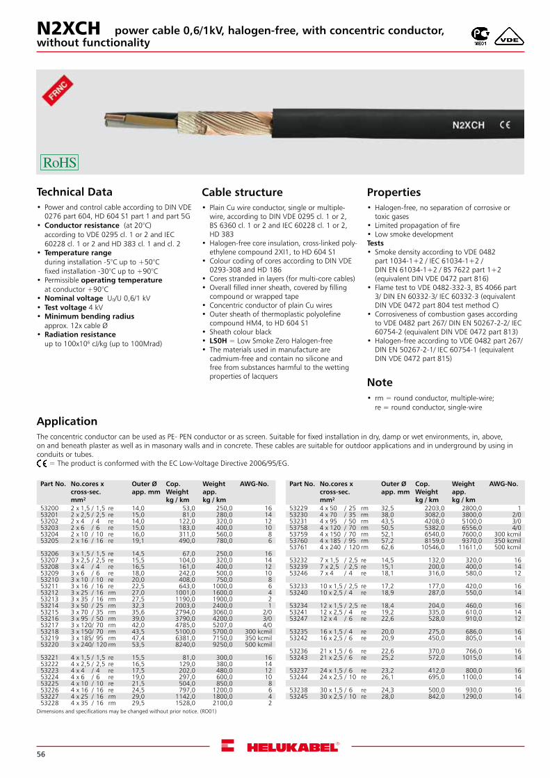
56
Dimensions and specifications may be changed without prior notice. (RO01)
Technical Data• Power and control cable according to DIN VDE
0276 part 604, HD 604 S1 part 1 and part 5G •Conductor resistance (at 20°C)
according to VDE 0295 cl. 1 or 2 and IEC 60228 cl. 1 or 2 and HD 383 cl. 1 and cl. 2
• Temperature rangeduring installation -5°C up to +50°Cfixed installation -30°C up to +90°C
• Permissible operating temperatureat conductor +90°C
•Nominal voltage U0/U 0,6/1 kV • Test voltage 4 kV •Minimum bending radius
approx. 12x cable Ø•Radiation resistance
up to 100x106 cJ/kg (up to 100Mrad)
ApplicationThe concentric conductor can be used as PE- PEN conductor or as screen. Suitable for fixed installation in dry, damp or wet environments, in, above, on and beneath plaster as well as in masonary walls and in concrete. These cables are suitable for outdoor applications and in underground by using in conduits or tubes. = The product is conformed with the EC Low-Voltage Directive 2006/95/EG.
Cable structure• Plain Cu wire conductor, single or multiple-
wire, according to DIN VDE 0295 cl. 1 or 2, BS 6360 cl. 1 or 2 and IEC 60228 cl. 1 or 2, HD 383
•Halogen-free core insulation, cross-linked poly-ethylene compound 2XI1, to HD 604 S1
• Colour coding of cores according to DIN VDE 0293-308 and HD 186
• Cores stranded in layers (for multi-core cables)•Overall filled inner sheath, covered by filling
compound or wrapped tape• Concentric conductor of plain Cu wires•Outer sheath of thermoplastic polyolefine
compound HM4, to HD 604 S1• Sheath colour black• LS0H = Low Smoke Zero Halogen-free• The materials used in manufacture are
cadmium-free and contain no silicone and free from substances harmful to the wetting properties of lacquers
Properties•Halogen-free, no separation of corrosive or
toxic gases• Limited propagation of fire• Low smoke development Tests• Smoke density according to VDE 0482
part 1034-1+2 / IEC 61034-1+2 / DIN EN 61034-1+2 / BS 7622 part 1+2 (equivalent DIN VDE 0472 part 816)
• Flame test to VDE 0482-332-3, BS 4066 part 3/ DIN EN 60332-3/ IEC 60332-3 (equivalent DIN VDE 0472 part 804 test method C)
• Corrosiveness of combustion gases according to VDE 0482 part 267/ DIN EN 50267-2-2/ IEC 60754-2 (equivalent DIN VDE 0472 part 813)
•Halogen-free according to VDE 0482 part 267/ DIN EN 50267-2-1/ IEC 60754-1 (equivalent DIN VDE 0472 part 815)
Note• rm = round conductor, multiple-wire;
re = round conductor, single-wire
N2XCHwithout functionality
power cable 0,6/1kV, halogen-free, with concentric conductor,
Part No. No.cores x cross-sec.mm²
Outer Øapp. mm
Cop. Weightkg / km
Weightapp. kg / km
AWG-No.
53200 2 x 1,5 / 1,5 re 14,0 53,0 250,0 1653201 2 x 2,5 / 2,5 re 15,0 81,0 280,0 1453202 2 x 4 / 4 re 14,0 122,0 320,0 1253203 2 x 6 / 6 re 15,0 183,0 400,0 1053204 2 x 10 / 10 re 16,0 311,0 560,0 853205 2 x 16 / 16 re 19,1 490,0 780,0 6
53206 3 x 1,5 / 1,5 re 14,5 67,0 250,0 1653207 3 x 2,5 / 2,5 re 15,5 104,0 320,0 1453208 3 x 4 / 4 re 16,5 161,0 400,0 1253209 3 x 6 / 6 re 18,0 242,0 500,0 1053210 3 x 10 / 10 re 20,0 408,0 750,0 853211 3 x 16 / 16 re 22,5 643,0 1000,0 653212 3 x 25 / 16 rm 27,0 1001,0 1600,0 453213 3 x 35 / 16 rm 27,5 1190,0 1900,0 253214 3 x 50 / 25 rm 32,3 2003,0 2400,0 153215 3 x 70 / 35 rm 35,6 2794,0 3060,0 2/053216 3 x 95 / 50 rm 39,0 3790,0 4200,0 3/053217 3 x 120/ 70 rm 42,0 4785,0 5207,0 4/053218 3 x 150/ 70 rm 43,5 5100,0 5700,0 300 kcmil53219 3 x 185/ 95 rm 47,4 6381,0 7150,0 350 kcmil53220 3 x 240/ 120 rm 53,5 8240,0 9250,0 500 kcmil
53221 4 x 1,5 / 1,5 re 15,5 81,0 300,0 1653222 4 x 2,5 / 2,5 re 16,5 129,0 380,0 1453223 4 x 4 / 4 re 17,5 202,0 480,0 1253224 4 x 6 / 6 re 19,0 297,0 600,0 1053225 4 x 10 / 10 re 21,5 504,0 850,0 853226 4 x 16 / 16 re 24,5 797,0 1200,0 653227 4 x 25 / 16 rm 29,0 1142,0 1800,0 453228 4 x 35 / 16 rm 29,5 1528,0 2100,0 2
Part No. No.cores x cross-sec.mm²
Outer Øapp. mm
Cop. Weightkg / km
Weightapp. kg / km
AWG-No.
53229 4 x 50 / 25 rm 32,5 2203,0 2800,0 153230 4 x 70 / 35 rm 38,0 3082,0 3800,0 2/053231 4 x 95 / 50 rm 43,5 4208,0 5100,0 3/053758 4 x 120 / 70 rm 50,5 5382,0 6556,0 4/053759 4 x 150 / 70 rm 52,1 6540,0 7600,0 300 kcmil53760 4 x 185 / 95 rm 57,2 8159,0 9370,0 350 kcmil53761 4 x 240 / 120 rm 62,6 10546,0 11611,0 500 kcmil
53232 7 x 1,5 / 2,5 re 14,5 132,0 320,0 1653239 7 x 2,5 / 2,5 re 15,1 200,0 400,0 1453246 7 x 4 / 4 re 18,1 316,0 580,0 12 53233 10 x 1,5 / 2,5 re 17,2 177,0 420,0 1653240 10 x 2,5 / 4 re 18,9 287,0 550,0 14
53234 12 x 1,5 / 2,5 re 18,4 204,0 460,0 1653241 12 x 2,5 / 4 re 19,2 335,0 610,0 1453247 12 x 4 / 6 re 22,6 528,0 910,0 12 53235 16 x 1,5 / 4 re 20,0 275,0 686,0 1653242 16 x 2,5 / 6 re 20,9 450,0 805,0 14
53236 21 x 1,5 / 6 re 22,6 370,0 766,0 1653243 21 x 2,5 / 6 re 25,2 572,0 1015,0 14 53237 24 x 1,5 / 6 re 23,2 412,0 800,0 1653244 24 x 2,5 / 10 re 26,1 695,0 1100,0 14
53238 30 x 1,5 / 6 re 24,3 500,0 930,0 1653245 30 x 2,5 / 10 re 28,0 842,0 1290,0 14

57
NYM-J/-O PVC-Sheathed Cable VDE-approved
Technical Data• PVC-sheathed cable to DIN VDE 0250 part 204 • Temperature range
Flexing +5°C up to +70°CFixed installation -40°C up to +70°C
•Nominal voltageU0/U 300/500 V
• Test voltage 2000 V •Minimum bending radius
Fixed installation 4x cable Ø •Radiation resistance
Up to 80x106 cJ/kg (up to 80 Mrad)
Cable structure• Solid or stranded, plain copper conductor to
DIN VDE 0295 cl. 1 or cl. 2, BS 6360 cl. 1 or cl. 2 and IEC 60228 cl. 1 or cl. 2
• PVC core insulation, TI1 to DIN VDE 0281 part 1
• Colour coded to DIN VDE 0293-308 • Cores stranded in layer • Special PVC outer sheath TM1, to
DIN VDE 0281 part 1 • Jacket colour grey (RAL 7035)
Properties• PVC self-extinguishing and flame
retardant according to VDE 0482-332-1-2, DIN EN 60332-1-2/ IEC 60332-1 (equivalent DIN VDE 0472 part 804 test method B)
Note• re = round conductor, single-wire;
rm = round conductor, multiple-wire.•G = with green-yellow earth core;
x = without green-yellow earth core (OZ).•AWG sizes are approximate equivalent values.
The actual cross-section is in mm².
Dimensions and specifications may be changed without prior notice. (RO01)
ApplicationFor industrial- and wiring purposes.Usable in the open, in dry, damp and wet environments in the open and concealed, as well as in masonry and in beton, not suitable for imbedding in solidified- or compressed-concrete. Outdoor usage is only possible, as long as the cable is protected against direct sunlight. = The product is conformed with the EC Low-Voltage Directive 2006/95/EG.
Part No. No.cores x cross-sec.mm²
Outer Øapp. mm
Cop. Weightkg / km
Weightapp. kg / km
AWG-No.
39050 1 G 1.5 re 5.4 14.4 40.0 1639001 1 x 1.5 re 5.4 14.4 40.0 1639006 2 x 1.5 re 8.7 29.0 170.0 1639056 3 G 1.5 re 9.1 43.0 135.0 1639007 3 x 1.5 re 9.1 43.0 135.0 1639058 4 G 1.5 re 9.8 58.0 160,0 1639009 4 x 1.5 re 9.8 58.0 160,0 1639066 5 G 1.5 re 10.3 72.0 190,0 1639017 5 x 1.5 re 10.3 72.0 190,0 1639072 7 G 1.5 re 11.5 101.0 235,0 1639023 7 x 1.5 re 11.5 101.0 235,0 1639076 10 G 1.5 re 13.8 144.0 330,0 1639077 12 G 1.5 re 14.4 173.0 405,0 16
39055 1 G 2.5 re 6.0 24.0 70,0 1439024 1 x 2.5 re 6.0 24.0 70,0 1439057 3 G 2.5 re 10.4 72.0 190,0 1439008 3 x 2.5 re 10.4 72.0 190,0 1439059 4 G 2.5 re 11.3 96.0 230,0 1439010 4 x 2.5 re 11.3 96.0 230.0 1439067 5 G 2.5 re 12.0 120.0 270.0 1439018 5 x 2.5 re 12.0 120.0 270.0 1439075 7 G 2.5 re 13.2 168.0 342.0 14
39051 1 G 4 re 6.6 38.0 80.0 1239002 1 x 4 re 6.6 38.0 80.0 1239074 3 G 4 re 12.0 115.0 258.0 1239060 4 G 4 re 13.0 154.0 330.0 1239011 4 x 4 re 13.0 154.0 330.0 1239068 5 G 4 re 14.5 192.0 410.0 1239019 5 x 4 re 14.5 192.0 410.0 12
Part No.
No.cores x cross-sec.mm²
Outer Øapp. mm
Cop. Weightkg / km
Weightapp. kg / km
AWG-No.
39052 1 G 6 re 7.2 58.0 105.0 1039003 1 x 6 re 7.2 58.0 105.0 1039078 3 G 6 re 13.0 173.0 320.0 1039061 4 G 6 re 15.1 230.0 460.0 1039012 4 x 6 re 15.1 230.0 460.0 1039069 5 G 6 re 16.1 288.0 540.0 1039020 5 x 6 re 16.1 288.0 540.0 10
39053 1 G 10 re 8.4 96.0 155.0 839004 1 x 10 re 8.4 96.0 155.0 839062 4 G 10 re 17.6 384.0 680.0 839013 4 x 10 re 17.6 384.0 680.0 839070 5 G 10 re 19.2 480.0 850.0 839021 5 x 10 re 19.2 480.0 850.0 8
39054 1 G 16 rm 9.9 154.0 230.0 639005 1 x 16 rm 9.9 154.0 230.0 639063 4 G 16 rm 21.3 614.0 1048.0 639014 4 x 16 rm 21.3 614.0 1048.0 639071 5 G 16 rm 23.4 768.0 1280.0 639022 5 x 16 rm 23.4 768.0 1280.0 6
39079 1 G 25 rm 12.0 240.0 325.0 439064 4 G 25 rm 25.8 960.0 1649.0 439015 4 x 25 rm 25.8 960.0 1649.0 439073 5 G 25 rm 28.7 1200.0 1970.0 4
39065 4 G 35 rm 28.5 1344.0 2000.0 239016 4 x 35 rm 28.5 1344.0 2000.0 2
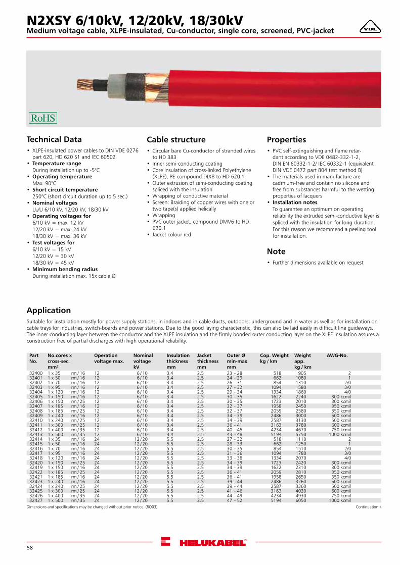
58
N2XSY 6/10kV, 12/20kV, 18/30kVMedium voltage cable, XLPE-insulated, Cu-conductor, single core, screened, PVC-jacket
Technical Data• XLPE-insulated power cables to DIN VDE 0276
part 620, HD 620 S1 and IEC 60502 • Temperature range
During installation up to -5°C •Operating temperature
Max. 90°C • Short circuit temperature
250°C (short circuit duration up to 5 sec.) •Nominal voltages
U0/U 6/10 kV, 12/20 kV, 18/30 kV •Operating voltages for
6/10 kV = max. 12 kV12/20 kV = max. 24 kV18/30 kV = max. 36 kV
• Test voltages for6/10 kV = 15 kV12/20 kV = 30 kV18/30 kV = 45 kV
•Minimum bending radiusDuring installation max. 15x cable Ø
ApplicationSuitable for installation mostly for power supply stations, in indoors and in cable ducts, outdoors, underground and in water as well as for installation on cable trays for industries, switch-boards and power stations. Due to the good laying characteristic, this can also be laid easily in difficult line guideways.The inner conducting layer between the conductor and the XLPE insulation and the firmly bonded outer conducting layer on the XLPE insulation assures a construction free of partial discharges with high operational reliability.
Cable structure• Circular bare Cu-conductor of stranded wires
to HD 383 • Inner semi-conducting coating • Core insulation of cross-linked Polyethylene
(XLPE), PE-compound DIX8 to HD 620.1 •Outer extrusion of semi-conducting coating
spliced with the insulation •Wrapping of conductive material • Screen: Braiding of copper wires with one or
two tape(s) applied helically •Wrapping • PVC outer jacket, compound DMV6 to HD
620.1 • Jacket colour red
Properties• PVC self-extinguishing and flame retar-
dant according to VDE 0482-332-1-2, DIN EN 60332-1-2/ IEC 60332-1 (equivalent DIN VDE 0472 part 804 test method B)
• The materials used in manufacture are cadmium-free and contain no silicone and free from substances harmful to the wetting properties of lacquers
• Installation notesTo guarantee an optimum on operating reliability the extruded semi-conductive layer is spliced with the insulation for long duration. For this reason we recommend a peeling tool for installation.
Note• Further dimensions available on request
Dimensions and specifications may be changed without prior notice. (RQ03) Continuation »
Part No.
No.cores x cross-sec.mm²
Operation voltage max.
Nominal voltage kV
Insulation thickness mm
Jacket thickness mm
Outer Ø min-max mm
Cop. Weightkg / km
Weightapp. kg / km
AWG-No.
32400 1 x 35 rm / 16 12 6 / 10 3.4 2.5 23 - 28 518 905 232401 1 x 50 rm / 16 12 6 / 10 3.4 2.5 24 - 29 662 1080 132402 1 x 70 rm / 16 12 6 / 10 3.4 2.5 26 - 31 854 1310 2/032403 1 x 95 rm / 16 12 6 / 10 3.4 2.5 27 - 32 1094 1580 3/032404 1 x 120 rm / 16 12 6 / 10 3.4 2.5 29 - 34 1334 1860 4/032405 1 x 150 rm / 16 12 6 / 10 3.4 2.5 30 - 35 1622 2240 300 kcmil32406 1 x 150 rm / 25 12 6 / 10 3.4 2.5 30 - 35 1723 2010 300 kcmil32407 1 x 185 rm / 16 12 6 / 10 3.4 2.5 32 - 37 1958 2450 350 kcmil32408 1 x 185 rm / 25 12 6 / 10 3.4 2.5 32 - 37 2059 2580 350 kcmil32409 1 x 240 rm / 16 12 6 / 10 3.4 2.5 34 - 39 2486 3000 500 kcmil32410 1 x 240 rm / 25 12 6 / 10 3.4 2.5 34 - 39 2587 3130 500 kcmil32411 1 x 300 rm / 25 12 6 / 10 3.4 2.5 36 - 41 3163 3780 600 kcmil32412 1 x 400 rm / 35 12 6 / 10 3.4 2.5 40 - 45 4234 4670 750 kcmil32413 1 x 500 rm / 35 12 6 / 10 3.4 2.5 43 - 48 5194 5750 1000 kcmil32414 1 x 35 rm / 16 24 12 / 20 5.5 2.5 27 - 32 518 1110 232415 1 x 50 rm / 16 24 12 / 20 5.5 2.5 28 - 33 662 1250 132416 1 x 70 rm / 16 24 12 / 20 5.5 2.5 30 - 35 854 1510 2/032417 1 x 95 rm / 16 24 12 / 20 5.5 2.5 31 - 36 1094 1780 3/032418 1 x 120 rm / 16 24 12 / 20 5.5 2.5 33 - 38 1334 2070 4/032420 1 x 150 rm / 25 24 12 / 20 5.5 2.5 34 - 39 1723 2420 300 kcmil32419 1 x 150 rm / 16 24 12 / 20 5.5 2.5 34 - 39 1622 2310 300 kcmil32422 1 x 185 rm / 25 24 12 / 20 5.5 2.5 36 - 41 2059 2810 350 kcmil32421 1 x 185 rm / 16 24 12 / 20 5.5 2.5 36 - 41 1958 2650 350 kcmil32423 1 x 240 rm / 16 24 12 / 20 5.5 2.5 39 - 44 2486 3260 500 kcmil32424 1 x 240 rm / 25 24 12 / 20 5.5 2.5 39 - 44 2587 3360 500 kcmil32425 1 x 300 rm / 25 24 12 / 20 5.5 2.5 41 - 46 3163 4020 600 kcmil32426 1 x 400 rm / 35 24 12 / 20 5.5 2.5 44 - 49 4234 4930 750 kcmil32427 1 x 500 rm / 35 24 12 / 20 5.5 2.5 47 - 52 5194 6050 1000 kcmil
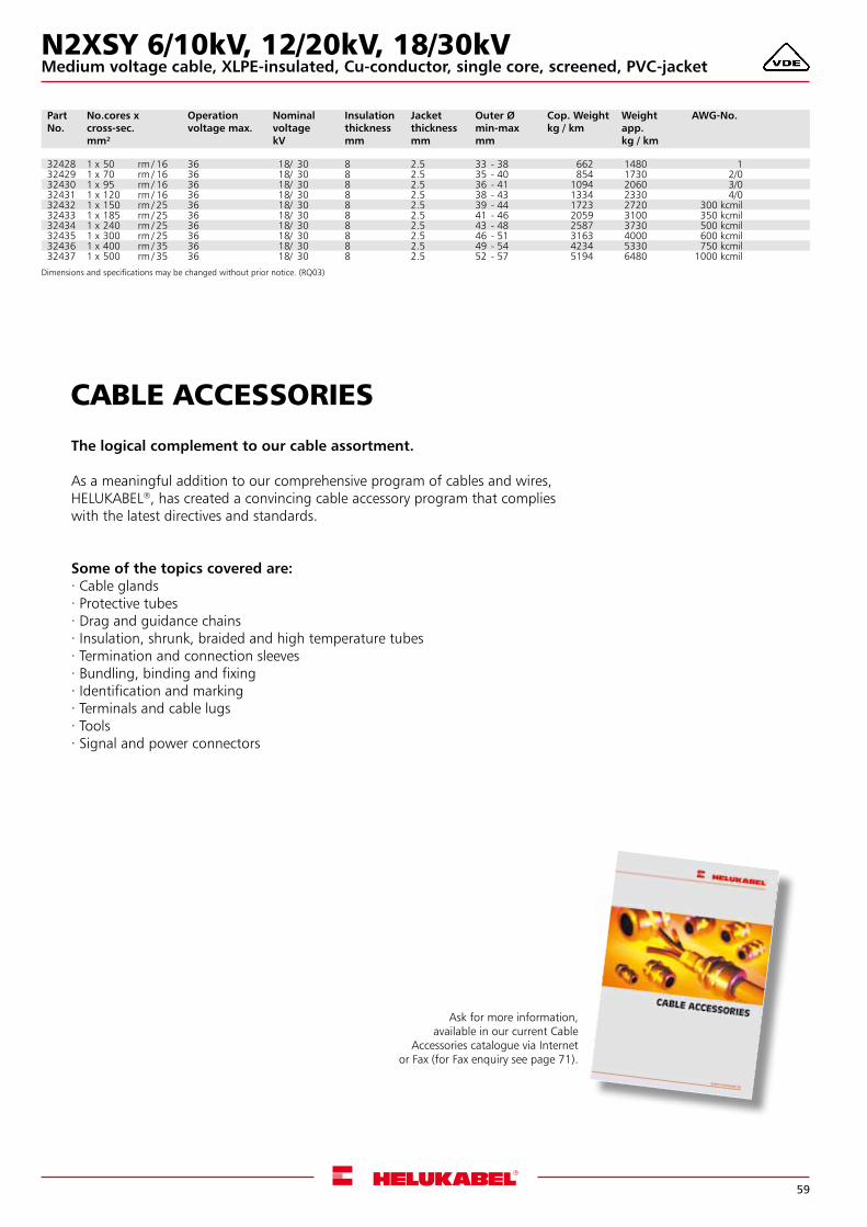
59
CABLE ACCESSORIES
The logical complement to our cable assortment.
As a meaningful addition to our comprehensive program of cables and wires, HELUKABEL®, has created a convincing cable accessory program that complies with the latest directives and standards.
Some of the topics covered are:. Cable glands. Protective tubes. Drag and guidance chains. Insulation, shrunk, braided and high temperature tubes. Termination and connection sleeves. Bundling, binding and fixing. Identification and marking. Terminals and cable lugs. Tools. Signal and power connectors
Ask for more information,available in our current Cable
Accessories catalogue via Internet or Fax (for Fax enquiry see page 71).
N2XSY 6/10kV, 12/20kV, 18/30kV
Part No.
No.cores x cross-sec.mm²
Operation voltage max.
Nominal voltage kV
Insulation thickness mm
Jacket thickness mm
Outer Ø min-max mm
Cop. Weightkg / km
Weightapp. kg / km
AWG-No.
32428 1 x 50 rm / 16 36 18/ 30 8 2.5 33 - 38 662 1480 132429 1 x 70 rm / 16 36 18/ 30 8 2.5 35 - 40 854 1730 2/032430 1 x 95 rm / 16 36 18/ 30 8 2.5 36 - 41 1094 2060 3/032431 1 x 120 rm / 16 36 18/ 30 8 2.5 38 - 43 1334 2330 4/032432 1 x 150 rm / 25 36 18/ 30 8 2.5 39 - 44 1723 2720 300 kcmil32433 1 x 185 rm / 25 36 18/ 30 8 2.5 41 - 46 2059 3100 350 kcmil32434 1 x 240 rm / 25 36 18/ 30 8 2.5 43 - 48 2587 3730 500 kcmil32435 1 x 300 rm / 25 36 18/ 30 8 2.5 46 - 51 3163 4000 600 kcmil32436 1 x 400 rm / 35 36 18/ 30 8 2.5 49 - 54 4234 5330 750 kcmil32437 1 x 500 rm / 35 36 18/ 30 8 2.5 52 - 57 5194 6480 1000 kcmil
Dimensions and specifications may be changed without prior notice. (RQ03)
Medium voltage cable, XLPE-insulated, Cu-conductor, single core, screened, PVC-jacket
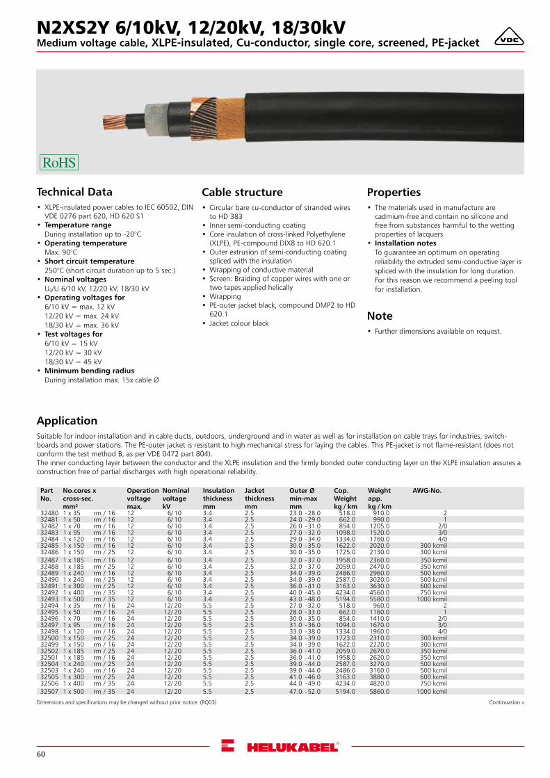
60
N2XS2Y 6/10kV, 12/20kV, 18/30kVMedium voltage cable, XLPE-insulated, Cu-conductor, single core, screened, PE-jacket
Technical Data• XLPE-insulated power cables to IEC 60502, DIN
VDE 0276 part 620, HD 620 S1 • Temperature range
During installation up to -20°C •Operating temperature
Max. 90°C • Short circuit temperature
250°C (short circuit duration up to 5 sec.) •Nominal voltages
U0/U 6/10 kV, 12/20 kV, 18/30 kV •Operating voltages for
6/10 kV = max. 12 kV12/20 kV = max. 24 kV18/30 kV = max. 36 kV
• Test voltages for6/10 kV = 15 kV12/20 kV = 30 kV18/30 kV = 45 kV
•Minimum bending radiusDuring installation max. 15x cable Ø
ApplicationSuitable for indoor installation and in cable ducts, outdoors, underground and in water as well as for installation on cable trays for industries, switch-boards and power stations. The PE-outer jacket is resistant to high mechanical stress for laying the cables. This PE-jacket is not flame-resistant (does not conform the test method B, as per VDE 0472 part 804).The inner conducting layer between the conductor and the XLPE insulation and the firmly bonded outer conducting layer on the XLPE insulation assures a construction free of partial discharges with high operational reliability.
Cable structure• Circular bare cu-conductor of stranded wires
to HD 383 • Inner semi-conducting coating • Core insulation of cross-linked Polyethylene
(XLPE), PE-compound DIX8 to HD 620.1 •Outer extrusion of semi-conducting coating
spliced with the insulation •Wrapping of conductive material • Screen: Braiding of copper wires with one or
two tapes applied helically •Wrapping • PE-outer jacket black, compound DMP2 to HD
620.1 • Jacket colour black
Properties• The materials used in manufacture are
cadmium-free and contain no silicone and free from substances harmful to the wetting properties of lacquers
• Installation notesTo guarantee an optimum on operating reliability the extruded semi-conductive layer is spliced with the insulation for long duration. For this reason we recommend a peeling tool for installation.
Note• Further dimensions available on request.
Dimensions and specifications may be changed without prior notice. (RQ03) Continuation »
Part No.
No.cores x cross-sec.mm²
Operation voltage max.
Nominal voltage kV
Insulation thickness mm
Jacket thickness mm
Outer Ø min-max mm
Cop. Weightkg / km
Weightapp. kg / km
AWG-No.
32480 1 x 35 rm / 16 12 6/ 10 3.4 2.5 23.0 -28.0 518.0 910.0 232481 1 x 50 rm / 16 12 6/ 10 3.4 2.5 24.0 -29.0 662.0 990.0 132482 1 x 70 rm / 16 12 6/ 10 3.4 2.5 26.0 -31.0 854.0 1205.0 2/032483 1 x 95 rm / 16 12 6/ 10 3.4 2.5 27.0 -32.0 1098.0 1520.0 3/032484 1 x 120 rm / 16 12 6/ 10 3.4 2.5 29.0 -34.0 1334.0 1760.0 4/032485 1 x 150 rm / 16 12 6/ 10 3.4 2.5 30.0 -35.0 1622.0 2020.0 300 kcmil32486 1 x 150 rm / 25 12 6/ 10 3.4 2.5 30.0 -35.0 1725.0 2130.0 300 kcmil32487 1 x 185 rm / 16 12 6/ 10 3.4 2.5 32.0 -37.0 1958.0 2360.0 350 kcmil32488 1 x 185 rm / 25 12 6/ 10 3.4 2.5 32.0 -37.0 2059.0 2470.0 350 kcmil32489 1 x 240 rm / 16 12 6/ 10 3.4 2.5 34.0 -39.0 2486.0 2960.0 500 kcmil32490 1 x 240 rm / 25 12 6/ 10 3.4 2.5 34.0 -39.0 2587.0 3020.0 500 kcmil32491 1 x 300 rm / 25 12 6/ 10 3.4 2.5 36.0 -41.0 3163.0 3630.0 600 kcmil32492 1 x 400 rm / 35 12 6/ 10 3.4 2.5 40.0 -45.0 4234.0 4560.0 750 kcmil32493 1 x 500 rm / 35 12 6/ 10 3.4 2.5 43.0 -48.0 5194.0 5580.0 1000 kcmil32494 1 x 35 rm / 16 24 12/ 20 5.5 2.5 27.0 -32.0 518.0 960.0 232495 1 x 50 rm / 16 24 12/ 20 5.5 2.5 28.0 -33.0 662.0 1160.0 132496 1 x 70 rm / 16 24 12/ 20 5.5 2.5 30.0 -35.0 854.0 1410.0 2/032497 1 x 95 rm / 16 24 12/ 20 5.5 2.5 31.0 -36.0 1094.0 1670.0 3/032498 1 x 120 rm / 16 24 12/ 20 5.5 2.5 33.0 -38.0 1334.0 1960.0 4/032500 1 x 150 rm / 25 24 12/ 20 5.5 2.5 34.0 -39.0 1723.0 2310.0 300 kcmil32499 1 x 150 rm / 16 24 12/ 20 5.5 2.5 34.0 -39.0 1622.0 2220.0 300 kcmil32502 1 x 185 rm / 25 24 12/ 20 5.5 2.5 36.0 -41.0 2059.0 2670.0 350 kcmil32501 1 x 185 rm / 16 24 12/ 20 5.5 2.5 36.0 -41.0 1958.0 2620.0 350 kcmil32504 1 x 240 rm / 25 24 12/ 20 5.5 2.5 39.0 -44.0 2587.0 3270.0 500 kcmil32503 1 x 240 rm / 16 24 12/ 20 5.5 2.5 39.0 -44.0 2486.0 3160.0 500 kcmil32505 1 x 300 rm / 25 24 12/ 20 5.5 2.5 41.0 -46.0 3163.0 3880.0 600 kcmil32506 1 x 400 rm / 35 24 12/ 20 5.5 2.5 44.0 -49.0 4234.0 4820.0 750 kcmil32507 1 x 500 rm / 35 24 12/ 20 5.5 2.5 47.0 -52.0 5194.0 5860.0 1000 kcmil
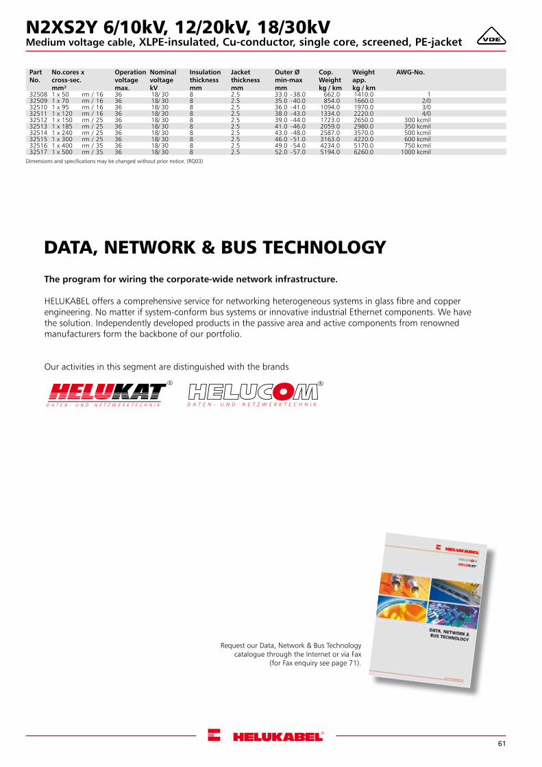
61
DATA, NETWORK & BUS TECHNOLOGY
The program for wiring the corporate-wide network infrastructure.
HELUKABEL offers a comprehensive service for networking heterogeneous systems in glass fibre and copper engineering. No matter if system-conform bus systems or innovative industrial Ethernet components. We havethe solution. Independently developed products in the passive area and active components from renowned manufacturers form the backbone of our portfolio.
Our activities in this segment are distinguished with the brands
Request our Data, Network & Bus Technologycatalogue through the Internet or via Fax
(for Fax enquiry see page 71).
N2XS2Y 6/10kV, 12/20kV, 18/30kV
Part No.
No.cores x cross-sec.mm²
Operation voltage max.
Nominal voltage kV
Insulation thickness mm
Jacket thickness mm
Outer Ø min-max mm
Cop. Weightkg / km
Weightapp. kg / km
AWG-No.
32508 1 x 50 rm / 16 36 18/ 30 8 2.5 33.0 -38.0 662.0 1410.0 132509 1 x 70 rm / 16 36 18/ 30 8 2.5 35.0 -40.0 854.0 1660.0 2/032510 1 x 95 rm / 16 36 18/ 30 8 2.5 36.0 -41.0 1094.0 1970.0 3/032511 1 x 120 rm / 16 36 18/ 30 8 2.5 38.0 -43.0 1334.0 2220.0 4/032512 1 x 150 rm / 25 36 18/ 30 8 2.5 39.0 -44.0 1723.0 2650.0 300 kcmil32513 1 x 185 rm / 25 36 18/ 30 8 2.5 41.0 -46.0 2059.0 2980.0 350 kcmil32514 1 x 240 rm / 25 36 18/ 30 8 2.5 43.0 -48.0 2587.0 3570.0 500 kcmil32515 1 x 300 rm / 25 36 18/ 30 8 2.5 46.0 -51.0 3163.0 4220.0 600 kcmil32516 1 x 400 rm / 35 36 18/ 30 8 2.5 49.0 -54.0 4234.0 5170.0 750 kcmil32517 1 x 500 rm / 35 36 18/ 30 8 2.5 52.0 -57.0 5194.0 6260.0 1000 kcmil
Dimensions and specifications may be changed without prior notice. (RQ03)
Medium voltage cable, XLPE-insulated, Cu-conductor, single core, screened, PE-jacket

62
NA2XS2Y 6/10kV, 12/20kV, 18/30kVMedium voltage cable, XLPE-insulated, alu-conductor, single-core, screened, PE-jacket
Technical Data• XLPE-insulated power cables to DIN VDE 0276
part 620, HD 620 S1 and IEC 60502 • Temperature range
During installation up to -20°C •Operating temperature
Max. 90°C • Short circuit temperature
250°C (short circuit duration up to 5 sec.) •Nominal voltages
U0/U 6/10 kV, 12/20 kV, 18/30 kV •Operating voltages for
6/10 kV = max. 12 kV12/20 kV = max. 24 kV18/30 kV = max. 36 kV
• Test voltages for6/10 kV = 15 kV12/20 kV = 30 kV18/30 kV = 45 kV
•Minimum bending radiusDuring installation max. 15x cable Ø
ApplicationSuitable for indoor installation and in cable ducts, outdoors, underground and in water as well as for installation on cable trays for industries, switch-boards and power stations. The PE-outer jacket is resistant to high mechanical stress for laying the cables. This PE-jacket is not flame-resistant (does not conform the test method B, as per VDE 0472 part 804).The inner conducting layer between the conductor and the XLPE insulation and the firmly bonded outer conducting layer on the XLPE insulation assures a construction free of partial discharges with high operational reliability.
Cable structure• Circular bare alu-conductor of stranded wires
to HD 383 • Inner semi-conducting coating • Core insulation of cross-linked Polyethylene
(XLPE), PE-compound DIX8 to HD 620.1 •Outer extrusion of semi-conducting coating
spliced with the insulation •Wrapping of conductive material • Screen: Braiding of copper wires with one or
two tapes applied helically •Wrapping • PE-outer jacket black, compound DMP2 to HD
620.1 • Jacket colour black
Properties• The materials used in manufacture are
cadmium-free and contain no silicone and free from substances harmful to the wetting properties of lacquers
• Installation notesTo guarantee an optimum on operating reliability the extruded semi-conductive layer is spliced with the insulation for long duration. For this reason we recommend a peeling tool for installation.
Note• Further dimensions available on request.
Dimensions and specifications may be changed without prior notice. (RQ03) Continuation »
Part No.
No.cores x cross-sec.mm²
Operation voltage max.
Nominal voltage kV
Insulation thickness mm
Jacket thickness mm
Outer Ø min-max mm
Cop. Weightkg / km
Alu-weightkg / km
Weightapp. kg / km
AWG-No.
32520 1 x 50 rm / 16 12 6 / 10 3.4 2.5 24.0 -29.0 182.0 145.0 710.0 132521 1 x 70 rm / 16 12 6 / 10 3.4 2.5 26.0 -31.0 182.0 203.0 790.0 2/032522 1 x 95 rm / 16 12 6 / 10 3.4 2.5 27.0 -32.0 182.0 276.0 920.0 3/032523 1 x 120 rm / 16 12 6 / 10 3.4 2.5 29.0 -34.0 182.0 348.0 990.0 4/032524 1 x 150 rm / 16 12 6 / 10 3.4 2.5 30.0 -35.0 182.0 435.0 1110.0 300 kcmil32525 1 x 150 rm / 25 12 6 / 10 3.4 2.5 30.0 -35.0 283.0 435.0 1220.0 300 kcmil32526 1 x 185 rm / 16 12 6 / 10 3.4 2.5 32.0 -37.0 182.0 537.0 1260.0 350 kcmil32527 1 x 185 rm / 25 12 6 / 10 3.4 2.5 32.0 -37.0 283.0 537.0 1370.0 350 kcmil32528 1 x 240 rm / 16 12 6 / 10 3.4 2.5 34.0 -39.0 182.0 696.0 1480.0 500 kcmil32529 1 x 240 rm / 25 12 6 / 10 3.4 2.5 34.0 -39.0 283.0 696.0 1530.0 500 kcmil32530 1 x 300 rm / 25 12 6 / 10 3.4 2.5 36.0 -41.0 283.0 870.0 1820.0 600 kcmil32531 1 x 400 rm / 35 12 6 / 10 3.4 2.5 40.0 -45.0 394.0 1160.0 2220.0 750 kcmil32532 1 x 500 rm / 35 12 6 / 10 3.4 2.5 43.0 -48.0 394.0 1450.0 2570.0 1000 kcmil32533 1 x 50 rm / 16 24 12 / 20 5.5 2.5 28.0 -33.0 182.0 145.0 890.0 132534 1 x 70 rm / 16 24 12 / 20 5.5 2.5 30.0 -35.0 182.0 203.0 970.0 2/032535 1 x 95 rm / 16 24 12 / 20 5.5 2.5 31.0 -36.0 182.0 276.0 1120.0 3/032536 1 x 120 rm / 16 24 12 / 20 5.5 2.5 33.0 -38.0 182.0 348.0 1210.0 4/032538 1 x 150 rm / 25 24 12 / 20 5.5 2.5 34.0 -39.0 283.0 435.0 1420.0 300 kcmil32537 1 x 150 rm / 16 24 12 / 20 5.5 2.5 34.0 -39.0 182.0 435.0 1370.0 300 kcmil32539 1 x 185 rm / 16 24 12 / 20 5.5 2.5 36.0 -41.0 182.0 537.0 1530.0 350 kcmil32540 1 x 185 rm / 25 24 12 / 20 5.5 2.5 36.0 -41.0 283.0 537.0 1570.0 350 kcmil32542 1 x 240 rm / 25 24 12 / 20 5.5 2.5 39.0 -44.0 283.0 696.0 1830.0 500 kcmil32541 1 x 240 rm / 16 24 12 / 20 5.5 2.5 39.0 -44.0 182.0 696.0 1720.0 500 kcmil32543 1 x 300 rm / 25 24 12 / 20 5.5 2.5 41.0 -46.0 283.0 870.0 2070.0 600 kcmil32544 1 x 400 rm / 35 24 12 / 20 5.5 2.5 44.0 -49.0 394.0 1160.0 2460.0 750 kcmil32545 1 x 500 rm / 35 24 12 / 20 5.5 2.5 47.0 -52.0 394.0 1450.0 2890.0 1000 kcmil
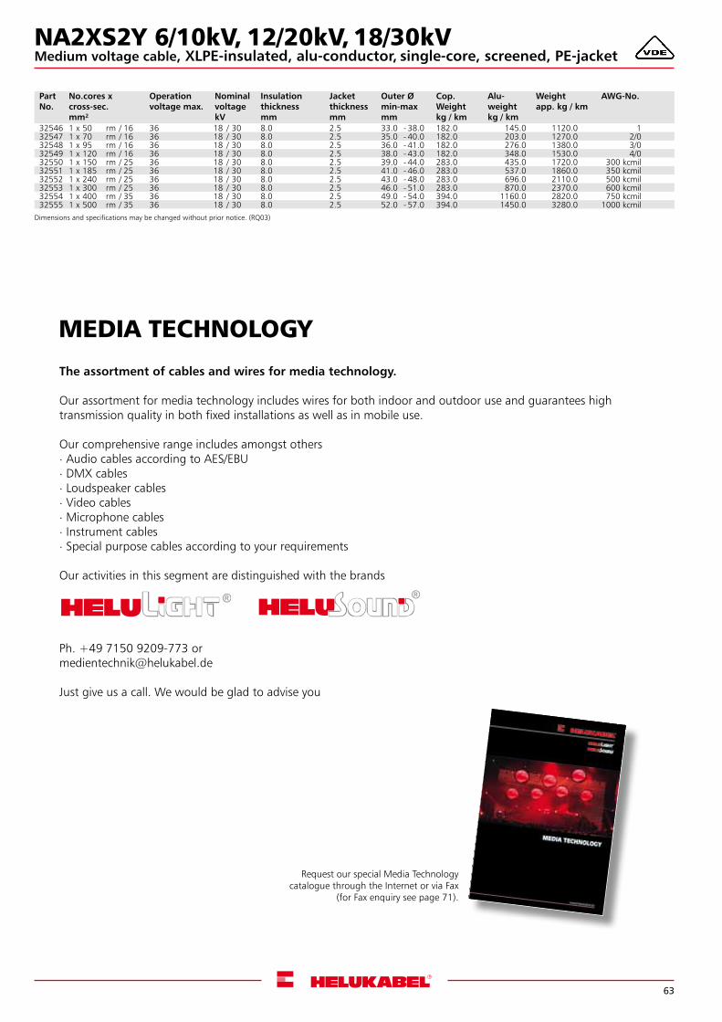
63
MEDIA TECHNOLOGY
The assortment of cables and wires for media technology.
Our assortment for media technology includes wires for both indoor and outdoor use and guarantees hightransmission quality in both fixed installations as well as in mobile use.
Our comprehensive range includes amongst others. Audio cables according to AES/EBU. DMX cables. Loudspeaker cables. Video cables. Microphone cables. Instrument cables. Special purpose cables according to your requirements
Our activities in this segment are distinguished with the brands
Ph. +49 7150 9209-773 [email protected]
Just give us a call. We would be glad to advise you
Request our special Media Technologycatalogue through the Internet or via Fax
(for Fax enquiry see page 71).
Dimensions and specifications may be changed without prior notice. (RQ03)
Part No.
No.cores x cross-sec.mm²
Operation voltage max.
Nominal voltage kV
Insulation thickness mm
Jacket thickness mm
Outer Ø min-max mm
Cop. Weightkg / km
Alu-weightkg / km
Weightapp. kg / km
AWG-No.
32546 1 x 50 rm / 16 36 18 / 30 8.0 2.5 33.0 - 38.0 182.0 145.0 1120.0 132547 1 x 70 rm / 16 36 18 / 30 8.0 2.5 35.0 - 40.0 182.0 203.0 1270.0 2/032548 1 x 95 rm / 16 36 18 / 30 8.0 2.5 36.0 - 41.0 182.0 276.0 1380.0 3/032549 1 x 120 rm / 16 36 18 / 30 8.0 2.5 38.0 - 43.0 182.0 348.0 1530.0 4/032550 1 x 150 rm / 25 36 18 / 30 8.0 2.5 39.0 - 44.0 283.0 435.0 1720.0 300 kcmil32551 1 x 185 rm / 25 36 18 / 30 8.0 2.5 41.0 - 46.0 283.0 537.0 1860.0 350 kcmil32552 1 x 240 rm / 25 36 18 / 30 8.0 2.5 43.0 - 48.0 283.0 696.0 2110.0 500 kcmil32553 1 x 300 rm / 25 36 18 / 30 8.0 2.5 46.0 - 51.0 283.0 870.0 2370.0 600 kcmil32554 1 x 400 rm / 35 36 18 / 30 8.0 2.5 49.0 - 54.0 394.0 1160.0 2820.0 750 kcmil32555 1 x 500 rm / 35 36 18 / 30 8.0 2.5 52.0 - 57.0 394.0 1450.0 3280.0 1000 kcmil
NA2XS2Y 6/10kV, 12/20kV, 18/30kVMedium voltage cable, XLPE-insulated, alu-conductor, single-core, screened, PE-jacket
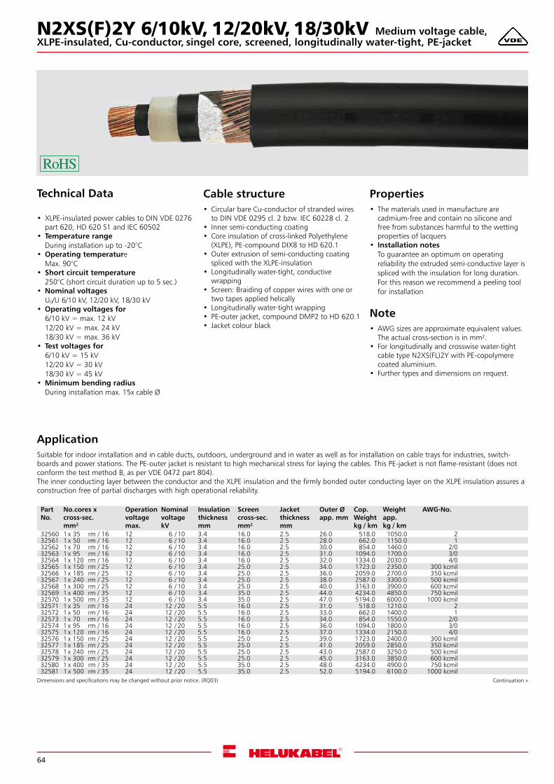
64
N2XS(F)2Y 6/10kV, 12/20kV, 18/30kVXLPE-insulated, Cu-conductor, singel core, screened, longitudinally water-tight, PE-jacket
Technical Data
• XLPE-insulated power cables to DIN VDE 0276 part 620, HD 620 S1 and IEC 60502
• Temperature rangeDuring installation up to -20°C
•Operating temperatureMax. 90°C
• Short circuit temperature250°C (short circuit duration up to 5 sec.)
•Nominal voltagesU0/U 6/10 kV, 12/20 kV, 18/30 kV
•Operating voltages for6/10 kV = max. 12 kV12/20 kV = max. 24 kV18/30 kV = max. 36 kV
• Test voltages for6/10 kV = 15 kV12/20 kV = 30 kV18/30 kV = 45 kV
•Minimum bending radiusDuring installation max. 15x cable Ø
ApplicationSuitable for indoor installation and in cable ducts, outdoors, underground and in water as well as for installation on cable trays for industries, switch-boards and power stations. The PE-outer jacket is resistant to high mechanical stress for laying the cables. This PE-jacket is not flame-resistant (does not conform the test method B, as per VDE 0472 part 804).The inner conducting layer between the conductor and the XLPE insulation and the firmly bonded outer conducting layer on the XLPE insulation assures a construction free of partial discharges with high operational reliability.
Cable structure• Circular bare Cu-conductor of stranded wires
to DIN VDE 0295 cl. 2 bzw. IEC 60228 cl. 2 • Inner semi-conducting coating • Core insulation of cross-linked Polyethylene
(XLPE), PE-compound DIX8 to HD 620.1 •Outer extrusion of semi-conducting coating
spliced with the XLPE-insulation • Longitudinally water-tight, conductive
wrapping • Screen: Braiding of copper wires with one or
two tapes applied helically • Longitudinally water-tight wrapping • PE-outer jacket, compound DMP2 to HD 620.1 • Jacket colour black
Properties• The materials used in manufacture are
cadmium-free and contain no silicone and free from substances harmful to the wetting properties of lacquers
• Installation notesTo guarantee an optimum on operating reliability the extruded semi-conductive layer is spliced with the insulation for long duration. For this reason we recommend a peeling tool for installation
Note•AWG sizes are approximate equivalent values.
The actual cross-section is in mm².• For longitudinally and crosswise water-tight
cable type N2XS(FL)2Y with PE-copolymere coated aluminium.
• Further types and dimensions on request.
Dimensions and specifications may be changed without prior notice. (RQ03) Continuation »
Part No.
No.cores x cross-sec.mm²
Operation voltage max.
Nominal voltage kV
Insulation thickness mm
Screen cross-sec.mm²
Jacket thickness mm
Outer Øapp. mm
Cop. Weightkg / km
Weightapp. kg / km
AWG-No.
32560 1 x 35 rm / 16 12 6 / 10 3.4 16.0 2.5 26.0 518.0 1050.0 232561 1 x 50 rm / 16 12 6 / 10 3.4 16.0 2.5 28.0 662.0 1150.0 132562 1 x 70 rm / 16 12 6 / 10 3.4 16.0 2.5 30.0 854.0 1460.0 2/032563 1 x 95 rm / 16 12 6 / 10 3.4 16.0 2.5 31.0 1094.0 1700.0 3/032564 1 x 120 rm / 16 12 6 / 10 3.4 16.0 2.5 32.0 1334.0 2030.0 4/032565 1 x 150 rm / 25 12 6 / 10 3.4 25.0 2.5 34.0 1723.0 2350.0 300 kcmil32566 1 x 185 rm / 25 12 6 / 10 3.4 25.0 2.5 36.0 2059.0 2700.0 350 kcmil32567 1 x 240 rm / 25 12 6 / 10 3.4 25.0 2.5 38.0 2587.0 3300.0 500 kcmil32568 1 x 300 rm / 25 12 6 / 10 3.4 25.0 2.5 40.0 3163.0 3900.0 600 kcmil32569 1 x 400 rm / 35 12 6 / 10 3.4 35.0 2.5 44.0 4234.0 4850.0 750 kcmil32570 1 x 500 rm / 35 12 6 / 10 3.4 35.0 2.5 47.0 5194.0 6000.0 1000 kcmil32571 1 x 35 rm / 16 24 12 / 20 5.5 16.0 2.5 31.0 518.0 1210.0 232572 1 x 50 rm / 16 24 12 / 20 5.5 16.0 2.5 33.0 662.0 1400.0 132573 1 x 70 rm / 16 24 12 / 20 5.5 16.0 2.5 34.0 854.0 1550.0 2/032574 1 x 95 rm / 16 24 12 / 20 5.5 16.0 2.5 36.0 1094.0 1800.0 3/032575 1 x 120 rm / 16 24 12 / 20 5.5 16.0 2.5 37.0 1334.0 2150.0 4/032576 1 x 150 rm / 25 24 12 / 20 5.5 25.0 2.5 39.0 1723.0 2400.0 300 kcmil32577 1 x 185 rm / 25 24 12 / 20 5.5 25.0 2.5 41.0 2059.0 2850.0 350 kcmil32578 1 x 240 rm / 25 24 12 / 20 5.5 25.0 2.5 43.0 2587.0 3250.0 500 kcmil32579 1 x 300 rm / 25 24 12 / 20 5.5 25.0 2.5 45.0 3163.0 3850.0 600 kcmil32580 1 x 400 rm / 35 24 12 / 20 5.5 35.0 2.5 48.0 4234.0 4900.0 750 kcmil32581 1 x 500 rm / 35 24 12 / 20 5.5 35.0 2.5 52.0 5194.0 6100.0 1000 kcmil
Medium voltage cable,
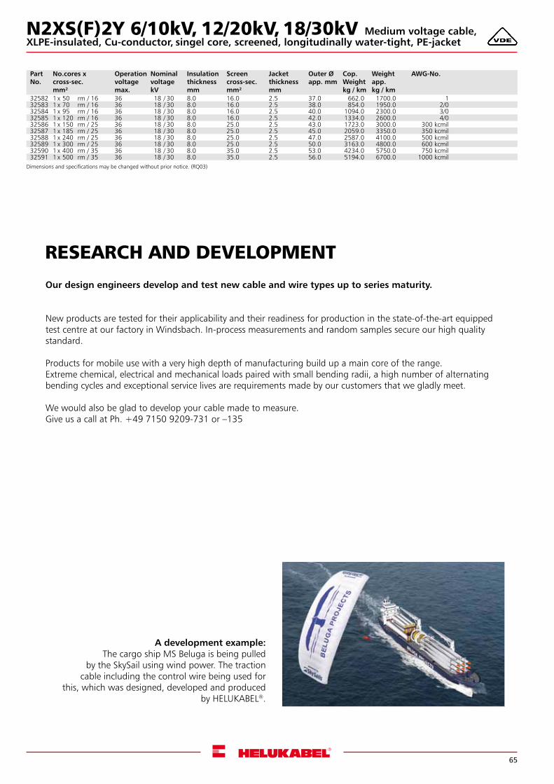
65
RESEARCH AND DEVELOPMENT
Our design engineers develop and test new cable and wire types up to series maturity.
New products are tested for their applicability and their readiness for production in the state-of-the-art equipped test centre at our factory in Windsbach. In-process measurements and random samples secure our high quality standard.
Products for mobile use with a very high depth of manufacturing build up a main core of the range.Extreme chemical, electrical and mechanical loads paired with small bending radii, a high number of alternating bending cycles and exceptional service lives are requirements made by our customers that we gladly meet.
We would also be glad to develop your cable made to measure.Give us a call at Ph. +49 7150 9209-731 or –135
A development example:The cargo ship MS Beluga is being pulled
by the SkySail using wind power. The traction cable including the control wire being used for
this, which was designed, developed and produced by HELUKABEL®.
Part No.
No.cores x cross-sec.mm²
Operation voltage max.
Nominal voltage kV
Insulation thickness mm
Screen cross-sec.mm²
Jacket thickness mm
Outer Øapp. mm
Cop. Weightkg / km
Weightapp. kg / km
AWG-No.
32582 1 x 50 rm / 16 36 18 / 30 8.0 16.0 2.5 37.0 662.0 1700.0 132583 1 x 70 rm / 16 36 18 / 30 8.0 16.0 2.5 38.0 854.0 1950.0 2/032584 1 x 95 rm / 16 36 18 / 30 8.0 16.0 2.5 40.0 1094.0 2300.0 3/032585 1 x 120 rm / 16 36 18 / 30 8.0 16.0 2.5 42.0 1334.0 2600.0 4/032586 1 x 150 rm / 25 36 18 / 30 8.0 25.0 2.5 43.0 1723.0 3000.0 300 kcmil32587 1 x 185 rm / 25 36 18 / 30 8.0 25.0 2.5 45.0 2059.0 3350.0 350 kcmil32588 1 x 240 rm / 25 36 18 / 30 8.0 25.0 2.5 47.0 2587.0 4100.0 500 kcmil32589 1 x 300 rm / 25 36 18 / 30 8.0 25.0 2.5 50.0 3163.0 4800.0 600 kcmil32590 1 x 400 rm / 35 36 18 / 30 8.0 35.0 2.5 53.0 4234.0 5750.0 750 kcmil32591 1 x 500 rm / 35 36 18 / 30 8.0 35.0 2.5 56.0 5194.0 6700.0 1000 kcmil
Dimensions and specifications may be changed without prior notice. (RQ03)
N2XS(F)2Y 6/10kV, 12/20kV, 18/30kVXLPE-insulated, Cu-conductor, singel core, screened, longitudinally water-tight, PE-jacket
Medium voltage cable,
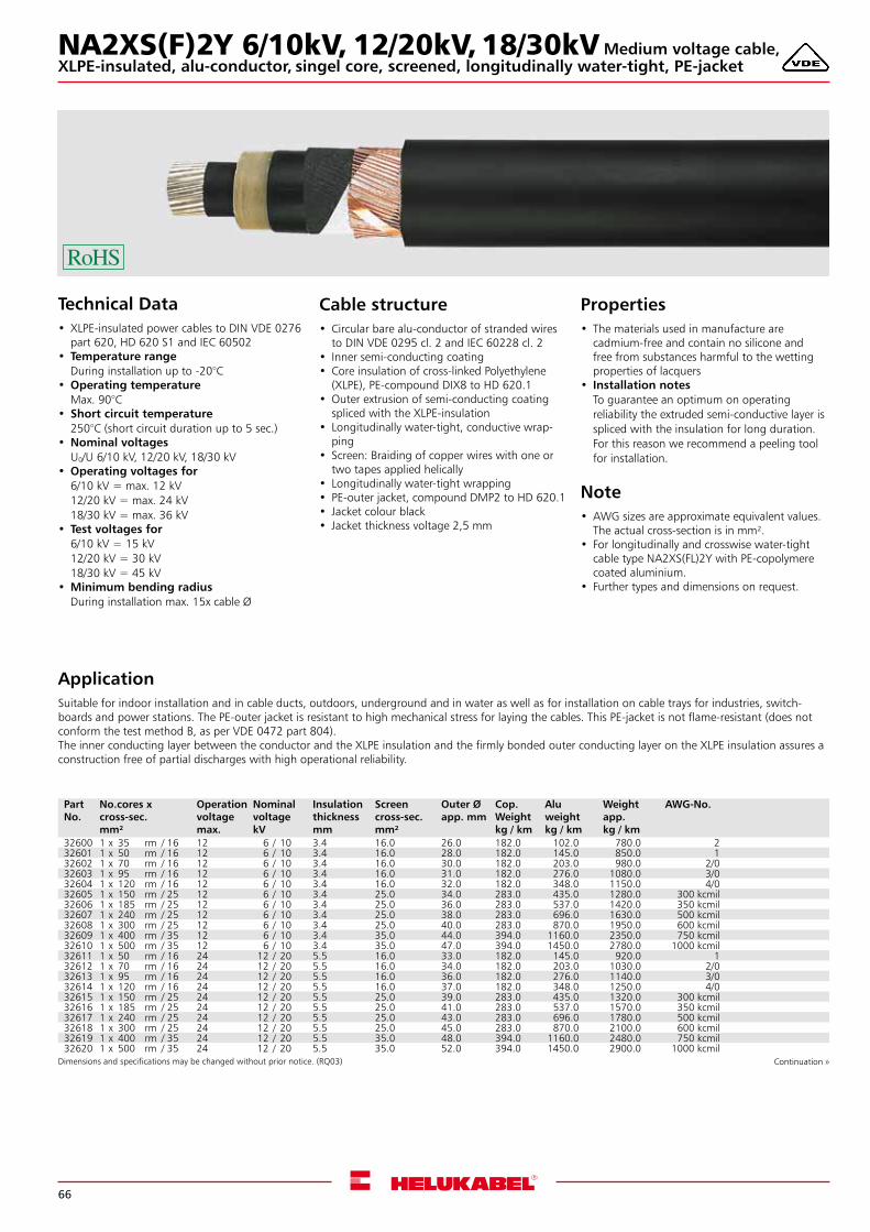
66
NA2XS(F)2Y 6/10kV, 12/20kV, 18/30kV
Technical Data• XLPE-insulated power cables to DIN VDE 0276
part 620, HD 620 S1 and IEC 60502 • Temperature range
During installation up to -20°C •Operating temperature
Max. 90°C • Short circuit temperature
250°C (short circuit duration up to 5 sec.) •Nominal voltages
U0/U 6/10 kV, 12/20 kV, 18/30 kV •Operating voltages for
6/10 kV = max. 12 kV12/20 kV = max. 24 kV18/30 kV = max. 36 kV
• Test voltages for6/10 kV = 15 kV12/20 kV = 30 kV18/30 kV = 45 kV
•Minimum bending radiusDuring installation max. 15x cable Ø
ApplicationSuitable for indoor installation and in cable ducts, outdoors, underground and in water as well as for installation on cable trays for industries, switch-boards and power stations. The PE-outer jacket is resistant to high mechanical stress for laying the cables. This PE-jacket is not flame-resistant (does not conform the test method B, as per VDE 0472 part 804).The inner conducting layer between the conductor and the XLPE insulation and the firmly bonded outer conducting layer on the XLPE insulation assures a construction free of partial discharges with high operational reliability.
Cable structure• Circular bare alu-conductor of stranded wires
to DIN VDE 0295 cl. 2 and IEC 60228 cl. 2 • Inner semi-conducting coating • Core insulation of cross-linked Polyethylene
(XLPE), PE-compound DIX8 to HD 620.1 •Outer extrusion of semi-conducting coating
spliced with the XLPE-insulation • Longitudinally water-tight, conductive wrap-
ping • Screen: Braiding of copper wires with one or
two tapes applied helically • Longitudinally water-tight wrapping • PE-outer jacket, compound DMP2 to HD 620.1 • Jacket colour black • Jacket thickness voltage 2,5 mm
Properties• The materials used in manufacture are
cadmium-free and contain no silicone and free from substances harmful to the wetting properties of lacquers
• Installation notesTo guarantee an optimum on operating reliability the extruded semi-conductive layer is spliced with the insulation for long duration. For this reason we recommend a peeling tool for installation.
Note•AWG sizes are approximate equivalent values.
The actual cross-section is in mm².• For longitudinally and crosswise water-tight
cable type NA2XS(FL)2Y with PE-copolymere coated aluminium.
• Further types and dimensions on request.
Dimensions and specifications may be changed without prior notice. (RQ03) Continuation »
Part No.
No.cores x cross-sec.mm²
Operation voltage max.
Nominal voltage kV
Insulation thickness mm
Screen cross-sec.mm²
Outer Øapp. mm
Cop. Weightkg / km
Alu weightkg / km
Weightapp. kg / km
AWG-No.
32600 1 x 35 rm / 16 12 6 / 10 3.4 16.0 26.0 182.0 102.0 780.0 232601 1 x 50 rm / 16 12 6 / 10 3.4 16.0 28.0 182.0 145.0 850.0 132602 1 x 70 rm / 16 12 6 / 10 3.4 16.0 30.0 182.0 203.0 980.0 2/032603 1 x 95 rm / 16 12 6 / 10 3.4 16.0 31.0 182.0 276.0 1080.0 3/032604 1 x 120 rm / 16 12 6 / 10 3.4 16.0 32.0 182.0 348.0 1150.0 4/032605 1 x 150 rm / 25 12 6 / 10 3.4 25.0 34.0 283.0 435.0 1280.0 300 kcmil32606 1 x 185 rm / 25 12 6 / 10 3.4 25.0 36.0 283.0 537.0 1420.0 350 kcmil32607 1 x 240 rm / 25 12 6 / 10 3.4 25.0 38.0 283.0 696.0 1630.0 500 kcmil32608 1 x 300 rm / 25 12 6 / 10 3.4 25.0 40.0 283.0 870.0 1950.0 600 kcmil32609 1 x 400 rm / 35 12 6 / 10 3.4 35.0 44.0 394.0 1160.0 2350.0 750 kcmil32610 1 x 500 rm / 35 12 6 / 10 3.4 35.0 47.0 394.0 1450.0 2780.0 1000 kcmil32611 1 x 50 rm / 16 24 12 / 20 5.5 16.0 33.0 182.0 145.0 920.0 132612 1 x 70 rm / 16 24 12 / 20 5.5 16.0 34.0 182.0 203.0 1030.0 2/032613 1 x 95 rm / 16 24 12 / 20 5.5 16.0 36.0 182.0 276.0 1140.0 3/032614 1 x 120 rm / 16 24 12 / 20 5.5 16.0 37.0 182.0 348.0 1250.0 4/032615 1 x 150 rm / 25 24 12 / 20 5.5 25.0 39.0 283.0 435.0 1320.0 300 kcmil32616 1 x 185 rm / 25 24 12 / 20 5.5 25.0 41.0 283.0 537.0 1570.0 350 kcmil32617 1 x 240 rm / 25 24 12 / 20 5.5 25.0 43.0 283.0 696.0 1780.0 500 kcmil32618 1 x 300 rm / 25 24 12 / 20 5.5 25.0 45.0 283.0 870.0 2100.0 600 kcmil32619 1 x 400 rm / 35 24 12 / 20 5.5 35.0 48.0 394.0 1160.0 2480.0 750 kcmil32620 1 x 500 rm / 35 24 12 / 20 5.5 35.0 52.0 394.0 1450.0 2900.0 1000 kcmil
XLPE-insulated, alu-conductor, singel core, screened, longitudinally water-tight, PE-jacketMedium voltage cable,
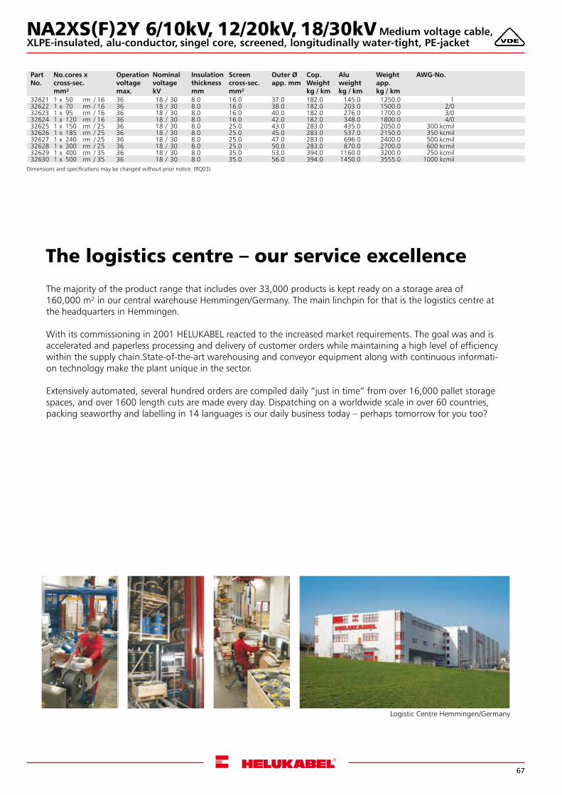
67
The logistics centre – our service excellence
The majority of the product range that includes over 33,000 products is kept ready on a storage area of 160,000 m² in our central warehouse Hemmingen/Germany. The main linchpin for that is the logistics centre at the headquarters in Hemmingen.
With its commissioning in 2001 HELUKABEL reacted to the increased market requirements. The goal was and isaccelerated and paperless processing and delivery of customer orders while maintaining a high level of efficiencywithin the supply chain.State-of-the-art warehousing and conveyor equipment along with continuous informati-on technology make the plant unique in the sector.
Extensively automated, several hundred orders are compiled daily “just in time” from over 16,000 pallet storage spaces, and over 1600 length cuts are made every day. Dispatching on a worldwide scale in over 60 countries, packing seaworthy and labelling in 14 languages is our daily business today – perhaps tomorrow for you too?
Logistic Centre Hemmingen/Germany
Part No.
No.cores x cross-sec.mm²
Operation voltage max.
Nominal voltage kV
Insulation thickness mm
Screen cross-sec.mm²
Outer Øapp. mm
Cop. Weightkg / km
Alu weightkg / km
Weightapp. kg / km
AWG-No.
32621 1 x 50 rm / 16 36 18 / 30 8.0 16.0 37.0 182.0 145.0 1250.0 132622 1 x 70 rm / 16 36 18 / 30 8.0 16.0 38.0 182.0 203.0 1500.0 2/032623 1 x 95 rm / 16 36 18 / 30 8.0 16.0 40.0 182.0 276.0 1700.0 3/032624 1 x 120 rm / 16 36 18 / 30 8.0 16.0 42.0 182.0 348.0 1800.0 4/032625 1 x 150 rm / 25 36 18 / 30 8.0 25.0 43.0 283.0 435.0 2050.0 300 kcmil32626 1 x 185 rm / 25 36 18 / 30 8.0 25.0 45.0 283.0 537.0 2150.0 350 kcmil32627 1 x 240 rm / 25 36 18 / 30 8.0 25.0 47.0 283.0 696.0 2400.0 500 kcmil32628 1 x 300 rm / 25 36 18 / 30 8.0 25.0 50.0 283.0 870.0 2700.0 600 kcmil32629 1 x 400 rm / 35 36 18 / 30 8.0 35.0 53.0 394.0 1160.0 3200.0 750 kcmil32630 1 x 500 rm / 35 36 18 / 30 8.0 35.0 56.0 394.0 1450.0 3555.0 1000 kcmil
Dimensions and specifications may be changed without prior notice. (RQ03)
NA2XS(F)2Y 6/10kV, 12/20kV, 18/30kVXLPE-insulated, alu-conductor, singel core, screened, longitudinally water-tight, PE-jacket
Medium voltage cable,
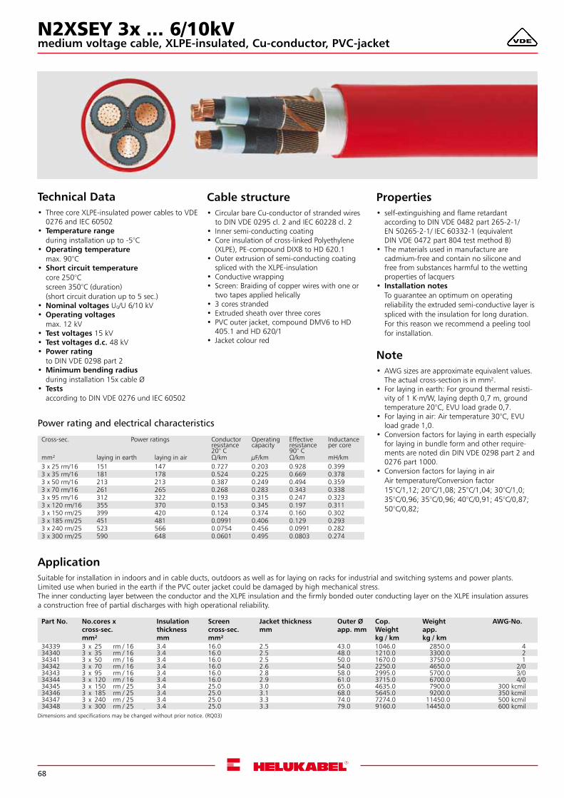
68
Technical Data• Three core XLPE-insulated power cables to VDE
0276 and IEC 60502 • Temperature range
during installation up to -5°C •Operating temperature
max. 90°C • Short circuit temperature
core 250°Cscreen 350°C (duration)(short circuit duration up to 5 sec.)
•Nominal voltages U0/U 6/10 kV •Operating voltages
max. 12 kV • Test voltages 15 kV • Test voltages d.c. 48 kV • Power rating
to DIN VDE 0298 part 2 •Minimum bending radius
during installation 15x cable Ø • Tests
according to DIN VDE 0276 und IEC 60502
ApplicationSuitable for installation in indoors and in cable ducts, outdoors as well as for laying on racks for industrial and switching systems and power plants. Limited use when buried in the earth if the PVC outer jacket could be damaged by high mechanical stress.The inner conducting layer between the conductor and the XLPE insulation and the firmly bonded outer conducting layer on the XLPE insulation assures a construction free of partial discharges with high operational reliability.
Cable structure• Circular bare Cu-conductor of stranded wires
to DIN VDE 0295 cl. 2 and IEC 60228 cl. 2 • Inner semi-conducting coating • Core insulation of cross-linked Polyethylene
(XLPE), PE-compound DIX8 to HD 620.1 •Outer extrusion of semi-conducting coating
spliced with the XLPE-insulation • Conductive wrapping • Screen: Braiding of copper wires with one or
two tapes applied helically • 3 cores stranded • Extruded sheath over three cores • PVC outer jacket, compound DMV6 to HD
405.1 and HD 620/1 • Jacket colour red
Properties• self-extinguishing and flame retardant
according to DIN VDE 0482 part 265-2-1/ EN 50265-2-1/ IEC 60332-1 (equivalent DIN VDE 0472 part 804 test method B)
• The materials used in manufacture are cadmium-free and contain no silicone and free from substances harmful to the wetting properties of lacquers
• Installation notesTo guarantee an optimum on operating reliability the extruded semi-conductive layer is spliced with the insulation for long duration. For this reason we recommend a peeling tool for installation.
Note•AWG sizes are approximate equivalent values.
The actual cross-section is in mm².• For laying in earth: For ground thermal resisti-
vity of 1 K·m/W, laying depth 0,7 m, ground temperature 20°C, EVU load grade 0,7.
• For laying in air: Air temperature 30°C, EVU load grade 1,0.
• Conversion factors for laying in earth especially for laying in bundle form and other require-ments are noted din DIN VDE 0298 part 2 and 0276 part 1000.
• Conversion factors for laying in airAir temperature/Conversion factor15°C/1,12; 20°C/1,08; 25°C/1,04; 30°C/1,0; 35°C/0,96; 35°C/0,96; 40°C/0,91; 45°C/0,87; 50°C/0,82;
Dimensions and specifications may be changed without prior notice. (RQ03) Roter Preis wird mit reduziertem Rabatt abgerechnet
Part No. No.cores x cross-sec.mm²
Insulation thickness mm
Screen cross-sec.mm²
Jacket thicknessmm
Outer Øapp. mm
Cop. Weightkg / km
Weightapp. kg / km
AWG-No.
34339 3 x 25 rm / 16 3.4 16.0 2.5 43.0 1046.0 2850.0 434340 3 x 35 rm / 16 3.4 16.0 2.5 48.0 1210.0 3300.0 234341 3 x 50 rm / 16 3.4 16.0 2.5 50.0 1670.0 3750.0 134342 3 x 70 rm / 16 3.4 16.0 2.6 54.0 2250.0 4650.0 2/034343 3 x 95 rm / 16 3.4 16.0 2.8 58.0 2995.0 5700.0 3/034344 3 x 120 rm / 16 3.4 16.0 2.9 61.0 3715.0 6700.0 4/034345 3 x 150 rm / 25 3.4 25.0 3.0 65.0 4635.0 7900.0 300 kcmil34346 3 x 185 rm / 25 3.4 25.0 3.1 68.0 5645.0 9200.0 350 kcmil34347 3 x 240 rm / 25 3.4 25.0 3.3 74.0 7274.0 11450.0 500 kcmil34348 3 x 300 rm / 25 3.4 25.0 3.3 79.0 9160.0 14450.0 600 kcmil
Cross-sec. Power ratings Conductor resistance 20° C
Operating capacity
Effective resistance 90° C
Inductance per core
mm² laying in earth laying in air Ω/km µF/km Ω/km mH/km3 x 25 rm/16 151 147 0.727 0.203 0.928 0.3993 x 35 rm/16 181 178 0.524 0.225 0.669 0.3783 x 50 rm/16 213 213 0.387 0.249 0.494 0.3593 x 70 rm/16 261 265 0.268 0.283 0.343 0.3383 x 95 rm/16 312 322 0.193 0.315 0.247 0.3233 x 120 rm/16 355 370 0.153 0.345 0.197 0.3113 x 150 rm/25 399 420 0.124 0.374 0.160 0.3023 x 185 rm/25 451 481 0.0991 0.406 0.129 0.2933 x 240 rm/25 523 566 0.0754 0.456 0.0991 0.2823 x 300 rm/25 590 648 0.0601 0.495 0.0803 0.274
Power rating and electrical characteristics
N2XSEY 3x ... 6/10kVmedium voltage cable, XLPE-insulated, Cu-conductor, PVC-jacket
Dimensions and specifications may be changed without prior notice. (RQ03)
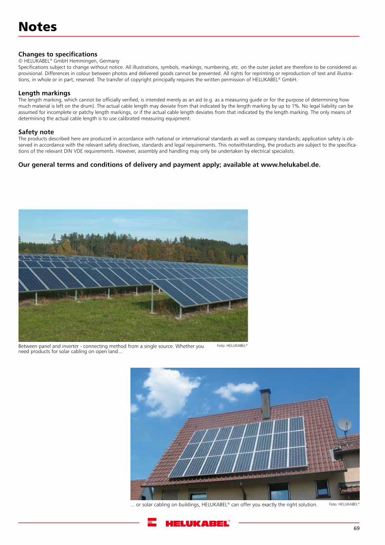
69
Foto: HELUKABEL®Between panel and inverter - connecting method from a single source. Whether you need products for solar cabling on open land...
... or solar cabling on buildings, HELUKABEL® can offer you exactly the right solution. Foto: HELUKABEL®
Notes
Changes to specifications© HELUKABEL® GmbH Hemmingen, GermanySpecifications subject to change without notice. All illustrations, symbols, markings, numbering, etc. on the outer jacket are therefore to be considered as provisional. Differences in colour between photos and delivered goods cannot be prevented. All rights for reprinting or reproduction of text and illustra-tions, in whole or in part, reserved. The transfer of copyright principally requires the written permission of HELUKABEL® GmbH.
Length markingsThe length marking, which cannot be officially verified, is intended merely as an aid (e.g. as a measuring guide or for the purpose of determining how much material is left on the drum). The actual cable length may deviate from that indicated by the length marking by up to 1%. No legal liability can be assumed for incomplete or patchy length markings, or if the actual cable length deviates from that indicated by the length marking. The only means of determining the actual cable length is to use calibrated measuring equipment.
Safety noteThe products described here are produced in accordance with national or international standards as well as company standards; application safety is ob-served in accordance with the relevant safety directives, standards and legal requirements. This notwithstanding, the products are subject to the specifica-tions of the relevant DIN VDE requirements. However, assembly and handling may only be undertaken by electrical specialists.
Our general terms and conditions of delivery and payment apply; available at www.helukabel.de.
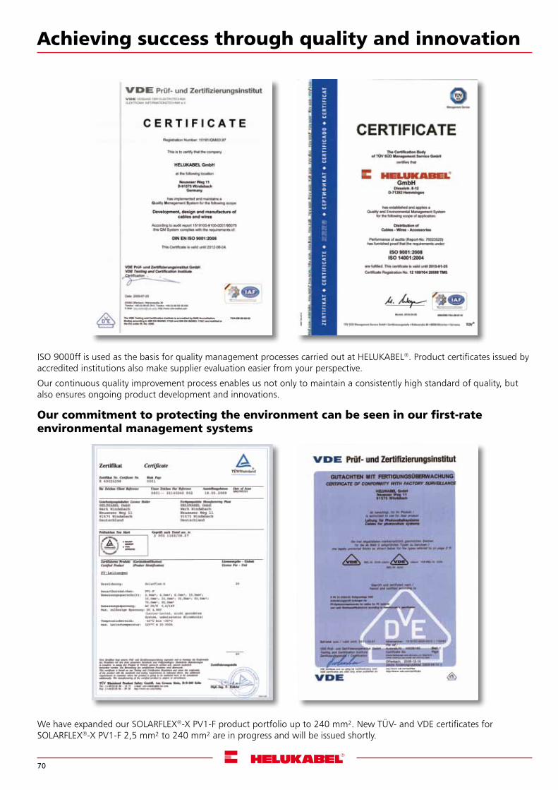
70
Achieving success through quality and innovation
ISO 9000ff is used as the basis for quality management processes carried out at HELUKABEL®. Product certificates issued by accredited institutions also make supplier evaluation easier from your perspective.
Our continuous quality improvement process enables us not only to maintain a consistently high standard of quality, but also ensures ongoing product development and innovations.
Our commitment to protecting the environment can be seen in our first-rate environmental management systems
We have expanded our SOLARFLEX®-X PV1-F product portfolio up to 240 mm². New TÜV- and VDE certificates for SOLARFLEX®-X PV1-F 2,5 mm² to 240 mm² are in progress and will be issued shortly.
www.helukabel.de
HELUKABEL® – global network
Sender (stamp)
Contacts
I would like to know more about HELUKABEL®.
Please send me the following catalogue: We would like:
Cables & Wires
Cable Accessories
Data, Network & Bus Technology
Media Technology
General documentation
A visit from a factory representative
A quotation for:
HELUKABEL® GmbHDieselstraße 8-12
71282 Hemmingen, GermanyPhone +49 7150 9209-0
Fax +49 7150 81786
Country Phone Fax e-MailHELUKABEL® Germany +49 7159 9209-0 +49 7150 81786 [email protected]
HELUKABEL® Switzerland +41 56 4181515 +41 56 4181516 [email protected]
HELUKABEL® Italy +39 039 9515450 +39 039 9281579 [email protected]
HELUKABEL® Poland +48 46 8580100 +48 46 8580117 [email protected]
HELUKABEL® Netherlands +31 495 499049 +31 495 499048 [email protected]
HELUKABEL® France +33 389 627562 +33 389 627700 [email protected]
HELUKABEL® Belgium +32 24 810020 +32 24 810022 [email protected]
HELUKABEL® China +86 21 5869 6108 +86 21 5869 3666 [email protected]
HELUKABEL® Sweden +46 8 7617805 +46 8 6210059 [email protected]
HELUKABEL® Czech Republic +42 0 312 672620 +42 0 312 672621 [email protected]
HELUKABEL® Russia +49 7150 9209389 +49 7150 922695 [email protected]
HELUKABEL® India +91 22 25185841 +91 22 25185839 [email protected]
HELUKABEL® Singapore +65 64 880170 +65 62 851513 [email protected]
HELUKABEL® Malaysia +603 7885 8724 +603 7885 7825 [email protected]® Korea +82 51 972 8646 +82 51 972 8649 [email protected]
HELUKABEL® Thailand +66 292735703 +66 29215402 [email protected]
HELUKABEL® Slovakia +42 19 15751549 +42 19 03595382 [email protected]
HELUKABEL® Turkey +90 212 5024195 +90 212 5024198 [email protected]
HELUKABEL® USA +01 847 9305118 +01 847 6228766 [email protected]
HELUKABEL® South Africa +27 11 4628752 +27 11 4628638 [email protected]
FAX enquiry form copy and fax straight forward (fax no. see above)
71
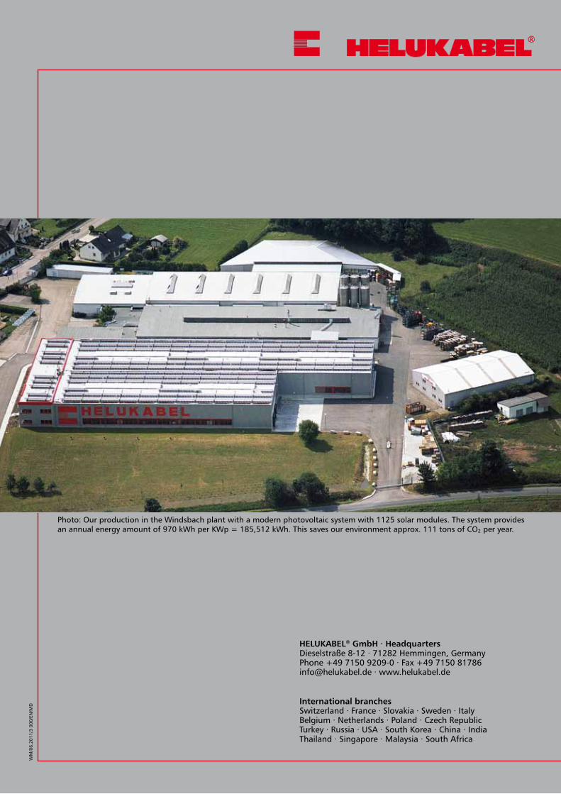
Contact details
HELUKABEL®GmbH∙HeadquartersDieselstraße 8-12 ∙ 71282 Hemmingen, GermanyPhone +49 7150 9209-0 ∙ Fax +49 7150 [email protected] ∙ www.helukabel.de
International branchesSwitzerland ∙ France ∙ Slovakia ∙ Sweden ∙ Italy Belgium ∙ Netherlands ∙ Poland ∙ Czech Republic Turkey ∙ Russia ∙ USA ∙ South Korea ∙ China ∙ India Thailand ∙ Singapore ∙ Malaysia ∙ South Africa
WM
/06.
2011
/3 0
00/E
N/M
D
Photo: Our production in the Windsbach plant with a modern photovoltaic system with 1125 solar modules. The system provides an annual energy amount of 970 kWh per KWp = 185,512 kWh. This saves our environment approx. 111 tons of CO² per year.