c60 sewage pumping station - mackay · pdf filewsaa sewage pumping station code of australia...
TRANSCRIPT

Construction Specification
C60
Sewage Pumping Station
Supplement to the WSAA Sewage Pumping Station Code of Australia
(WSA 04-2005 Version 2.1)
Revision 3 September 2012

Document Control
Rev Date Clause Details Author Verifier Approver
1 15/03/2006 - Original Version
2 02/02/2008 All Generally revised version with major amendments
3 All Full revision

TABLE OF CONTENTS
Preface ....................................................................................................................................... 7
Part 0: Glossary of Terms, Abbreviations and References .......... 8 III REFERENCED DOCUMENTS ...................................................................................................... 8
Part 3: Construction ............................................................. 9 17 GENERAL ............................................................................................................................... 9
17.1 Scope .................................................................................................................................. 9
17.2 Interpretation ......................................................................................................................... 9
18 QUALITY............................................................................................................................... 11
18.1 Quality Assurance ................................................................................................................ 11
18.1.2 Quality management system ............................................................................................ 11
18.1.5 Inspection and test plans ................................................................................................. 11
18.1.7 Quality audits ................................................................................................................ 11
18.2 Personnel Qualifications ........................................................................................................ 11
19 GENERAL CONSTRUCTION .................................................................................................... 13
19.1 General.............................................................................................................................. 13
19.5 Protection of People, Property and Environment ......................................................................... 13
19.5.1 Safety of People ............................................................................................................ 13
19.5.2 Protection of Other Services ............................................................................................. 13
19.5.3 Disused / Redundant sewers and pressure mains ................................................................. 13
19.5.5 Private and public properties ............................................................................................ 14
19.6 Affected Party Notifications .................................................................................................... 14
20 PRODUCTS, MATERIALS AND EQUIPMENT .............................................................................. 15
20.1 Authorised Products and Materials ........................................................................................... 15
20.1.1 Pressure pipe-work and pipe fittings ................................................................................... 15
20.1.2 Valves ......................................................................................................................... 17
20.1.3 Electrically operated actuators .......................................................................................... 18
20.2 Rejected Products and Materials ............................................................................................. 20
20.4 Pumps ............................................................................................................................... 20
20.5 Transportation, Handling and Storage of Products and Materials .................................................... 21
20.8 Fasteners ........................................................................................................................... 21
20.9 Works Inspection and Testing ................................................................................................. 21
20.9.1 Switchboards ................................................................................................................ 21
20.9.2 Pumps ......................................................................................................................... 22
20.9.3 Motors ......................................................................................................................... 22
20.9.4 Definitions .................................................................................................................... 22
20.9.5 Works Testing – In General .............................................................................................. 22
20.9.6 Switchgear and Controlgear Assembly (SCA) ...................................................................... 23
20.9.7 Mechanical Equipment .................................................................................................... 24
20.9.8 Valves ......................................................................................................................... 25
20.10 Concrete Works ................................................................................................................. 26
21 ELECTRICAL WORKS............................................................................................................. 28
21.2 Scope of Work ..................................................................................................................... 28
21.4 Consumer Mains .................................................................................................................. 28
21.4.6 Mains Requirements ....................................................................................................... 28
21.5 Earthing ............................................................................................................................. 29
21.5.1 General ....................................................................................................................... 29
21.6 Switchboard Installation ......................................................................................................... 29
21.6.1 General ....................................................................................................................... 29
21.10 Installation of Level Sensors ................................................................................................. 29
21.10.2 Wet-well level sensor probes .......................................................................................... 29
24 MECHANICAL INSTALLATION OF PUMPS, VALVES AND FITTINGS ............................................. 31
24.1 General.............................................................................................................................. 31
24.2 Flanged Joints ..................................................................................................................... 31
24.4 Gauges and Recorders ......................................................................................................... 31
24.4.1 Pressure Gauges ........................................................................................................... 31
24.4.3 Electromagnetic Flowmeters and Flow Switches ................................................................... 32
26 ACCESS ROAD AND HARDSTAND AREAS................................................................................ 33
27 RETAINING WALLS ................................................................................................................ 33
28 EXCAVATION ........................................................................................................................ 34
28.1 Safety ................................................................................................................................ 34
28.2 Limits of Excavation .............................................................................................................. 34
28.6 Support of Excavations.......................................................................................................... 34
28.8 Foundations and Foundation Stabilization ................................................................................. 35
28.9 Surplus Excavated Material .................................................................................................... 35
29 BEDDING FOR PIPES, BENDS, WET-WELLS AND MAINTENANCE STRUCTURES .......................... 36
29.1 Trench Floor Preparation ....................................................................................................... 36
29.2 Bedding Materials ................................................................................................................ 36
29.3 Placement of Bedding ........................................................................................................... 36
29.6 Bedding for Concrete Structures .............................................................................................. 36
29.7 Bedding for Maintenance shafts and Variable Bends.................................................................... 37
30 PIPE LAYING AND JOINTING ................................................................................................... 38
30.1 Installation of Pipes .............................................................................................................. 38
30.1.1 General ....................................................................................................................... 38
30.1.2 Cleaning, inspection and joint preparation ........................................................................... 38
30.1.4 Laying ......................................................................................................................... 38
30.2 Horizontal and Vertical Deflection of Gravity and Pressure Mains ................................................... 39
30.2.1 General ....................................................................................................................... 39
30.2.2 Methods of Deflection ..................................................................................................... 39

30.2.3 Horizontal curves ........................................................................................................... 39
30.2.4 Vertical curves .............................................................................................................. 39
30.2.5 Compound curves .......................................................................................................... 39
30.3 Horizontal and vertical separation of crossing pipelines ................................................................ 39
30.4 Flotation Control .................................................................................................................. 40
30.5 Thrust and Anchor Blocks and Restrained Joints for Pressure Mains ............................................... 40
30.6 Marking Tapes .................................................................................................................... 40
30.6.2 Detectable Marking Tape ................................................................................................. 40
30.8 Bored Pipes under Roads, Driveways and Elsewhere .................................................................. 40
30.10 Trench Stops for Pressure Mains ........................................................................................... 41
30.11 Bulkheads for Pressure Mains ............................................................................................... 41
30.12 Corrosion Protection of Cast Iron ........................................................................................... 42
30.14 Location Markers ................................................................................................................ 42
30.16 Welding of Steel Pressure Mains ........................................................................................... 42
30.16.1 General ...................................................................................................................... 42
31 WET-WELLS AND MAINTENANCE HOLES (MHS) ....................................................................... 43
31.1 General.............................................................................................................................. 43
31.4 Precast Concrete Systems ..................................................................................................... 43
31.7 Internal Coating of Concrete Wet-wells and MHs ........................................................................ 43
31.8 Covers ............................................................................................................................... 44
31.8.1 Maintenance Holes ........................................................................................................ 44
31.8.2 Wet-wells and Valve Pit ................................................................................................... 44
32 PIPE EMBEDMENT AND SUPPORT .......................................................................................... 45
32.2 Embedment Materials ........................................................................................................... 45
32.3 Compaction of Embedment .................................................................................................... 45
32.3.1 General ....................................................................................................................... 45
32.3.2 Methods ...................................................................................................................... 45
32.6 Concrete Embedment and Encasement .................................................................................... 45
33 FILL ..................................................................................................................................... 46
33.1 Trench Fill .......................................................................................................................... 46
33.1.1 General ....................................................................................................................... 46
33.1.2 Material Requirements .................................................................................................... 46
33.1.3 Compaction of Trench Fill ................................................................................................ 46
34 CONNECTION TO EXISTING GRAVITY SEWERS ........................................................................ 47
35 RESTORATION ...................................................................................................................... 49
35.1 General.............................................................................................................................. 49
35.2 Pavements ......................................................................................................................... 49
35.6 Provision for Settlement......................................................................................................... 49
35.7 Maintenance of Restored Surfaces .......................................................................................... 49
36 ACCEPTANCE TESTING ......................................................................................................... 50
36.1 Pipelines ............................................................................................................................ 50

36.3 Compaction Testing .............................................................................................................. 50
36.3.4 Trench fill compaction testing ........................................................................................... 50
36.3.4.4 Frequency and location of tests ...................................................................................... 50
36.4 Air Pressure and Vacuum Testing of Gravity Sewers ................................................................... 50
36.4.3 Testing of concrete emergency storage and maintenance structures ......................................... 50
36.4.3.1 General ..................................................................................................................... 50
36.5 Hydrostatic Pressure Testing of Pressure Mains ......................................................................... 51
36.5.1 General ....................................................................................................................... 51
36.5.2 System test pressure ...................................................................................................... 51
36.5.3 Maximum allowable loss .................................................................................................. 51
36.5.4 Test Procedure .............................................................................................................. 52
36.9 Electrical Works ................................................................................................................... 52
36.10 Sewage Pumping Station Site Testing ..................................................................................... 52
36.11 Detectable Marking Tape ..................................................................................................... 53
37 COMMISSIONING ................................................................................................................... 55
37.1 General.............................................................................................................................. 55
37.2 Pumping Station .................................................................................................................. 55
37.2.2 Pre-Commissioning ........................................................................................................ 55
37.2.3 Commissioning .............................................................................................................. 56
37.2.4 Handover ..................................................................................................................... 57
38 TOLERANCES ON AS-CONSTRUCTED WORK ........................................................................... 58
38.2 Vertical Tolerances ............................................................................................................... 58
32.2.1 Sewers, pressure mains, structures, pumping stations, roads .................................................. 58
39 WORK AS-CONSTRUCTED DETAILS ........................................................................................ 59
39.1 General.............................................................................................................................. 59
39.3 Operations and Maintenance Manuals ...................................................................................... 59
Appendix A ............................................................................................................................ 61
Appendix B ............................................................................................................................ 77
Appendix C ............................................................................................................................ 79
Appendix D ............................................................................................................................ 83

Preface The construction of sewage pumping stations and associated infrastructure must comply with the Water Services Association of Australia publication ‘WSA 04-2005 Version 2.1 – Sewage Pumping Station Code of Australia’ (the ‘Code’) except where the Code is amended by this document. The following amendments, additions, deletions and alterations apply to and form part of the Code. Section and Clause numbers refer to those in the Code. The standard drawings contained in the Code do not apply. Refer to the Mackay Regional Council standard drawings. Ultimately, this document will include amendments, additions, deletions and alterations to Part 1 'Planning and Design' of the Code so as to form a complete supplement to the Code. At this time the amendments, additions, deletions and alterations to Part 1 'Planning and Design' of the Code are included in the Mackay Regional Council document 'Development Design Guideline - Sewerage System Design - Planning Scheme Policy No. 15.14.

Part 0: Glossary of Terms, Abbreviations and References III REFERENCED DOCUMENTS (Add the following) The latest edition of all referenced documents, including all amendments and supplements, are to be used. The following documents are referred to in this Code;
a) Council Planning Scheme Policies
No. 15.14 - ‘Development Design Guideline - Sewerage System Design’ No. 16.03 - ‘Water Supply & Sewerage Infrastructure Contributions Policy’
b) Mackay Water Policies
MW02 – ‘Building Over and Adjacent to Sewers’ 063 – ‘Clearances to Water & Sewerage Assets’
c) Council Engineering Design Guidelines D20 – ‘Drawings and Documentation Guidelines’
g) Council Standard Drawings
d) WSAA Codes of Practice,
WSA 02-2002 – Sewerage Code of Australia WSA 04-2005 – Sewage Pumping Station Code of Australia WSA 101-2008 – Industry Standard for Submersible Pumps for Sewage Pumping Stations e) Water Services Specification, WS-SPEC : 2000 f) Australian Standards
h) Other Documents
‘Guide to Codes and Practices for Streets Opening’ (NSW Streets Opening Conference, 2009). ‘Planning Guidelines for Water Supply and Sewerage’ (Department of Environment and Resource management, April 2010) MEW E101 ‘Electrical Services Minimum Requirement’ (NSW Government , Public Works, NSW Water Solutions, September 2007)

Part 3: Construction 17 GENERAL 17.1 Scope ` (Add the following) Any inconsistency or ambiguity between the various documents comprising this Specification shall be resolved by the adoption of those documents in the following order of precedence;
a) Statutory Legislation b) This Specification c) Mackay Regional Council Standard Drawings d) Mackay Regional Council Standard Specifications e) Mackay Regional Council Standard Policies f) Sewerage Code of Australia (WSA 04-2005 Version 2.1) g) Water Services Specification, WS-SPEC:2000 h) Australian Standards
The work must comply with relevant Statutory Legislation, Codes of Practice, Australian Standards and Council’s local laws, policies, guidelines and specifications. This Specification applies in the construction of the various elements of a sewage pumping station system and a sewer rising main system which include, but are not limited to;
a) sewage pumping stations of capacity up to and including 200litres/second b) pressure mains of a size up to and including DN375 c) maintenance structures d) standard appurtenances
Construction of gravity sewers and associated gravity maintenance structures shall be in accordance with the requirements of WSA 02-2002 ‘Sewerage Code of Australia’. 17.2 Interpretation (Add the following) Asset Creation means any or all aspects of the planning, design, construction, supervision of construction, testing and commissioning and eventual handover of sewerage infrastructure to Mackay Regional Council. Contractor means a person, corporation, company, business or other legal entity bound under law to execute work under a contract or agreement. Contractor also means ‘Constructor’. Council means Mackay Regional Council and the Mackay Water & Waste business unit of Mackay Regional Council. Designer means a Professional Engineer who is qualified in Queensland (currently met by a person being registered as a Registered Professional Engineer Queensland (RPEQ) and is competent to perform the engineering works required for the Asset Creation process on behalf of a Developer. Developer means the person who has submitted a planning application for the provision of infrastructure under the Asset Creation process or for the utilisation of existing sewerage infrastructure.

HOLD POINT means a point beyond which work may not proceed (the Hold Point released) without authorisation, and sign-off, by the Superintendent’s representative and/or Mackay Regional Council’s representative. Release of a hold point may also be subject to an inspection of works by the Superintendent’s representative and/or Mackay Regional Council’s representative. IDAS means the Integrated Development Application System under the Sustainable Planning Act (SPA) Maintenance Structure means manhole, maintenance hole, pressure main discharge chamber, receiving access chamber or non-entry maintenance chamber MRC means the Mackay Regional Council MONITOR means intermittent surveillance of any stage of the work in progress by the Superintendent and/or the Superintendent’s Representative and/or the principal’s representative and/or Mackay Regional Council’s representative. SELF INSPECT means the progressive verification of the quality, and/or adherence to construction specifications, by the constructor/service provider and Principal Constructor (Contractor) performing the work. Confirmation of completion of Self Inspect requirements shall be by constructor checklist sign-off. Surveyor means a person, registered as a Surveyor (minimum Class – ‘individual’) with the Surveyors Board of Queensland under the Surveyors Act of Queensland, who is competent to perform the surveying work required of the works described in this document and the documents referenced herein. Sewer Reticulation means sewer pipe work less than DN375 to which property connections are permissible. SCA means Switch-gear and Control-gear Assembly and includes main switchboard, main distribution board, distribution board, control board, electrical kiosk, electrical panel, control panel or similar enclosure. SPA means the Queensland Sustainable Planning Act 2009. The Code means the Sewage Pumping Station Code of Australia (WSA 04-2005 Version 2.1) published by the Water Supply Association of Australia (WSAA). Trunk Mains means pipe work equal to or greater than DN375 in diameter and to which property connections are not permissible or generally not present. WITNESS POINT means a point beyond which work may not proceed without the Contractor notifying the Superintendent’s representative and/or Mackay Regional Council’s representative in order to provide the Superintendent’s representative and/or Mackay Regional Council’s representative with the opportunity to witness, and sign-off, an inspection or test or aspect of the work. The Superintendent’s representative and/or Mackay Regional Council’s representative, at their discretion, may authorise the inspection or test or aspect of the work to proceed without the Superintendent’s representative and/or Mackay Regional Council’s representative witnessing, and signing off, the inspection or test or aspect of the work. WS-SPEC means the Water Services Specification (2000) published by NSW Department of Public Works and Services.

18 QUALITY 18.1 Quality Assurance 18.1.2 Quality management system (Add the following) Prior to works commencing the Contractor must submit to the Superintendent evidence of its certification to the CCF Code (or equivalent). The Superintendent shall submit all certification evidence to Council prior to works commencing. Submission of certification evidence to the Superintendent constitutes a HOLD POINT. Release of the Hold Point via signoff by the Superintendent, subject to the Superintendent’s review and confirmation of the certification, is required prior to works commencing. 18.1.5 Inspection and test plans (Add the following) Council has prepared an Inspection and Test Plan (ITP) based on the WSAA Sewage Pumping Station Code of Australia and the amendments to the Code detailed in this document. The Contractor’s ITP must include, at least, all the details contained within the Council prepared ITP. 18.1.7 Quality audits (Add the following) Witness Points and Hold Points are specified within this document and referred documents for works described within this document and referred documents. It is the Constructors/Contractors responsibility to advise the Superintendent and/or Council of the anticipated or planned occurrence of any construction process/aspect or Inspection activity/aspect for which there is an associated Witness Point or Hold Point. 18.2 Personnel Qualifications (Add the following) All concrete and excavation work, including tunnelling, must be performed and supervised by appropriately-qualified and/or appropriately-accredited personnel. In particular Leading Hands, Supervisors and CCTV Operators must hold Statements of Attainment for Units of Competence (from either the Water Industry National Training Package NWP07, the Civil Construction Training Package RII09 or a training organisation’s training course/package acceptable to Council) pertaining to the particular tasks or work that they are engaged in. Prior to the commencement of any work Leading Hand, Supervisor and CCTV Operator qualifications must be submitted to the Superintendent. The Superintendent shall then submit all qualification/accreditation documentation to Council for Council review. Submission of all qualification/accreditation documentation to the Superintendent constitutes a HOLD POINT. The Superintendents review and acceptance of the nominated personnel to perform their nominated duties constitutes release of the Hold Point. Works must not commence until the Hold Point is released.

Submission of all qualification/accreditation documentation to Council constitutes a WITNESS POINT. Council shall advise the Superintendent at the time of submission whether the Witness Point is to be exercised. If exercised, Council’s review and acceptance of the nominated personnel to perform their nominated duties constitutes release of the Witness Point. Works must not commence until the Witness Point is released.

19 GENERAL CONSTRUCTION 19.1 General (Add the following) The Contractor must provide all necessary plant, equipment, labour, and materials required to satisfy the intent and/or requirements of this specification. The Contractor must comply with the requirements of all relevant Authorities including, but not limited to, having regard for stormwater management, dewatering effects/impacts, silt control, noise abatement, proximity to existing buildings and the amenity of adjacent property owners. Excavations for structures and pipelines must be performed to the lines, grades and forms shown on the Drawings, or as directed by the Superintendent, and within the specified tolerances. 19.5 Protection of People, Property and Environment 19.5.1 Safety of People (Add the following) The Contractor must comply with relevant Statutory and OH&S requirements when cutting and disposing of asbestos-cement pipes and materials. 19.5.2 Protection of Other Services (Add the following) Prior to works commencing the Contractor must locate all existing utilities and services and protect them from damage and interference. Where it is necessary to relocate or alter any existing utility or service the Contractor must make all necessary arrangements with, and comply with the requirements of, the relevant authorities. Further to notification requirements, the Contractor must immediately repair damage to any existing utility or service to the satisfaction of the utility or service owner, the Council and the Superintendent. The Contractor is responsible for all costs associated with rectification of the utility or service regardless of the accuracy of any prior location information provided by the Superintendent, Council, the utility service owner or its agent. All costs associated with the location, protection, and repair of all services must be borne by the Contractor. 19.5.3 Disused / Redundant sewers and pressure mains (Add the following) Unless noted otherwise, existing sewers and pressure mains that are no longer required it must be;
a) removed if < 1.5m deep, or b) filled with flowable cementitious grout if ≥ 1.5m deep, or c) filled with flowable cementitious grout if located under a structure (including roadways), or

d) filled with flowable cementitious grout if a structure is located within the sewer's or pressure main's zones of influence
Existing maintenance structures that are no longer required must be removed. Depth shall be measured from top of sewer/pressure main to finished surface level or from top of sewer/pressure main to top of finished pavement subgrade level; whichever is the lesser. 19.5.5 Private and public properties (Add the following) Excavated materials must not be stockpiled against any fence or the walls of any building. 19.6 Affected Party Notifications (Add the following) For all notifications the period of notice must be 5 (five) working days.

20 PRODUCTS, MATERIALS AND EQUIPMENT 20.1 Authorised Products and Materials (Add the following) 20.1.1 Pressure pipe-work and pipe fittings (This clause 20.1.1 is a new clause) Requirements for pressure pipe-work and pipe fittings are as follows:
a) Polyvinyl Chloride (PVC) Pipe and Fittings
PVC pressure pipe must be;
i) PVC-M or PVC-O ii) Series 2 (compatible with ductile iron (DI) pipe) iii) rubber ring (elastomeric seal) jointed iv) Class PN16 (minimum) v) Cream in colour (neither lighter than RAL 080 90 20, nor darker than RAL 075 80 20) vi) compliant with Section SP4 of WS-SPEC
Fittings must be Ductile Iron. Pipes and fittings must be handled, transported and stored as per manufacturer’s guidelines.
Further to the requirements of AS2032 ‘Installation of PVC pipe systems’ all PVC pipes installed to operate in direct sunlight must be painted (primer coat and double top coat) with a light coloured water-based acrylic paint.
b) Ductile Iron (DI) Pipe and Fittings
Ductile Iron pipe and fittings shall be;
i) rubber ring (elastomeric seal) jointed or flanged ii) PE sleeved (Colour – Cream) iii) cement mortar (type SR cement) lined or epoxy lined iv) Class PN35 v) compliant with Section SP2 of WS-SPEC.
Flanges shall be;
i) to Figures B5 & B6 of AS 4087, as appropriate ii) provided with Grade 316 SS bolts and Grade 304 SS nuts and washers
Pipe and fittings are to be handled, transported and stored as per manufacturer’s guidelines. Pipes and fittings cast into concrete must be treated, cleaned and prepared (including power-tool cleaned) in accordance with AS 1627.2 ‘Metal finishing – Preparation and pretreatment of surfaces Part 2: Power tool cleaning’.
c) Polyethylene (PE) Pipe and Fittings
PE Pipe and Fittings shall be;

i) electro-fusion, butt-fusion or compression joined ii) a minimum of class PN16 iii) compliant with Section SP6 of WS-SPEC iv) of either PE80B or PE100 polymer material. v) compliant with WS-SPEC Section SP6 ‘Polyethylene pipes and fittings’.
Fittings shall be;
i) (for fittings ≤ DN110mm) - PE in accordance with AS4129 ii) (for fittings > DN110mm) - DI in accordance with AS2280 and coated internally &
externally with PE in accordance with AS4129
Pipe must be of the required internal diameter shown in the design drawings. Pipes and fittings are to be handled, transported and stored as per manufacturer’s guidelines.
d) Steel Pipe and Fittings Steel pipe and fittings shall be;
i) rubber ring jointed, flanged or welded ii) Fusion bonded polyethylene (FBPE, e.g. Sintakote) or epoxy coated iii) SR type cement or epoxy lined iv) Minimum wall thickness the greater of 6mm or diameter/120 v) Compliant with Section SP1 of WS-SPEC
Flanges shall be;
i) to Figures B7, B8 & B9 of AS 4087, as appropriate ii) provided with Grade 316 SS bolts and Grade 304 SS nuts and washers
Steel pipe must be provided with cathodic protection where specified.
Pipe and fittings are to be handled, transported and stored as per manufacturer’s guidelines.
e) Glass Reinforced Plastic (GRP) Pipe and Fittings
GRP pipes and fittings must only be used with Council approval on a project-specific basis. If approved, GRP pipe and fittings shall be;
i) joined with rubber ring (elastomeric) jointed couplings ii) of a minimum pipe stiffness rating of SN10 iii) a minimum of class PN16 pressure iv) compliant with WS-SPEC Section SP5 ‘GRP pipes and fittings’.
All exposed GRP pipe work must be painted (primer coat and double top coat) with a light coloured water-based acrylic paint. Pipes and fittings are to be handled, transported and stored as per manufacturer’s guidelines.
f) ABS Pipe and Fittings
ABS pipe and fittings shall be;
i) Solvent welded

ii) minimum class PN16 pressure.
Joining of pipe shall be in accordance with the manufacturer’s instructions. Pipes and fittings are to be handled, transported and stored as per manufacturer’s guidelines.
g) Copper Pipe and Fittings
Copper pipe and fittings shall be;
i) manufactured in accordance with AS 1432 ii) in the range of DN6 to DN200 for Type A or Type B iii) insulated from ferrous mains iv) in compliance with AS3500 ‘Plumbing and drainage Part 2: Sanitary plumbing and
drainage’
Fittings shall;
i) comply with AS 3688 ‘Water supply – Metallic fittings and end connectors’ ii) be de-zincification resistant iii) , if capillary fittings, have silver brazed joints or solder insert capillary joints
20.1.2 Valves . (This clause 20.1.2 is a new clause) Requirements for valves are as follows:
a) General valve requirements
All valves are to be anti-clockwise close type.
Flange connections for valves must comply with AS4087 ‘Metallic flanges for waterworks purposes’ (or AS2129 ‘Flanges for pipes, valves and fittings’ where appropriate) and have a minimum pressure rating PN16. Bolts must be Grade SS316. Nuts and washers must be Grade SS304.
All ferrous alloy (cast iron, spheroidal graphite cast iron, plain carbon and alloy steel) valves must have protective epoxy coatings complying with WS-SPEC Section SP-30 ‘Protective Coatings for Valves’.
Oil valves and repack valve glands if directed by the Superintendent.
b) Knife Gate Valves shall be;
i) compliant with WS-SPEC Section SP23 ‘Knife gate valves’. ii) flanged unless noted otherwise on the Drawings.
c) Air Valves shall be;
i) compliant with WS-SPEC Section SP-27 ‘Air valves’ ii) a minimum size of DN80mm iii) provided with an isolating sluice valve iv) Ventomat (Council nominated make)

d) Sluice Valves shall be;
i) provided to each pump connection pipe work in the valve pit ii) flanged unless shown otherwise on the Drawings iii) resilient seated compliant with WS-SPEC Section SP-21 ‘sluice valves resilient
seated’.
e) Non-return Valves shall be;
i) provided to each discharge pipe in the valve pit. ii) resilient seated Val-Matic swing-flex check valves (Council nominated make)
f) Ball Valves shall be;
i) compliant with WS- SPEC Section SP-22 ‘Ball valves’ ii) flanged unless noted otherwise on the Drawings.
g) Butterfly Valves shall be;
i) only used with prior approval of Council ii) if approved, compliant with WS-SPEC Section SP-24 ‘Butterfly valves waterworks
purposes’ iii) if approved, flanged, unless noted otherwise on the Drawings.
h) Scour Valves shall be;
i) sluice valves ii) have assemblies as noted on the Drawings.
20.1.3 Electrically operated actuators (This clause 20.1.3 is a new clause) Requirements for electrically operated actuators are as follows;
a) General
Electrically operated actuators shall
i) be selected to be interchangeable with existing actuators where works augment existing sewerage infrastructure
ii) be selected subject to Council approval
b) Electrical properties
Electrically operated actuators shall
i) be 3 phase with a rated voltage of 415V 50Hz ii) be suitable for operation over a phase voltage range of 400V to 440 V. iii) have phase rotation protection integral with 3 phase actuators.
c) Installation
Electrically operated actuators shall
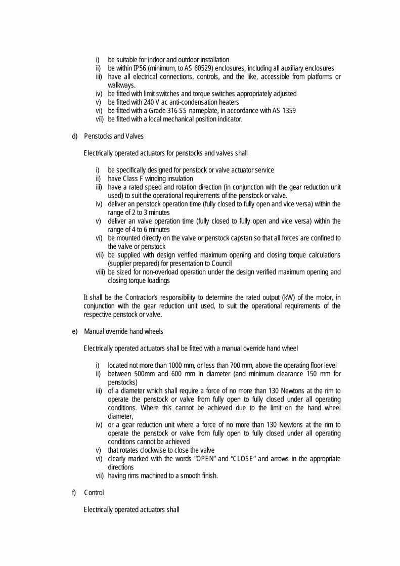
i) be suitable for indoor and outdoor installation ii) be within IP56 (minimum, to AS 60529) enclosures, including all auxiliary enclosures iii) have all electrical connections, controls, and the like, accessible from platforms or
walkways. iv) be fitted with limit switches and torque switches appropriately adjusted v) be fitted with 240 V ac anti-condensation heaters vi) be fitted with a Grade 316 SS nameplate, in accordance with AS 1359 vii) be fitted with a local mechanical position indicator.
d) Penstocks and Valves
Electrically operated actuators for penstocks and valves shall
i) be specifically designed for penstock or valve actuator service ii) have Class F winding insulation iii) have a rated speed and rotation direction (in conjunction with the gear reduction unit
used) to suit the operational requirements of the penstock or valve. iv) deliver an penstock operation time (fully closed to fully open and vice versa) within the
range of 2 to 3 minutes v) deliver an valve operation time (fully closed to fully open and vice versa) within the
range of 4 to 6 minutes vi) be mounted directly on the valve or penstock capstan so that all forces are confined to
the valve or penstock vii) be supplied with design verified maximum opening and closing torque calculations
(supplier prepared) for presentation to Council viii) be sized for non-overload operation under the design verified maximum opening and
closing torque loadings
It shall be the Contractor's responsibility to determine the rated output (kW) of the motor, in conjunction with the gear reduction unit used, to suit the operational requirements of the respective penstock or valve.
e) Manual override hand wheels
Electrically operated actuators shall be fitted with a manual override hand wheel
i) located not more than 1000 mm, or less than 700 mm, above the operating floor level ii) between 500mm and 600 mm in diameter (and minimum clearance 150 mm for
penstocks) iii) of a diameter which shall require a force of no more than 130 Newtons at the rim to
operate the penstock or valve from fully open to fully closed under all operating conditions. Where this cannot be achieved due to the limit on the hand wheel diameter,
iv) or a gear reduction unit where a force of no more than 130 Newtons at the rim to operate the penstock or valve from fully open to fully closed under all operating conditions cannot be achieved
v) that rotates clockwise to close the valve vi) clearly marked with the words "OPEN” and “CLOSE” and arrows in the appropriate
directions vii) having rims machined to a smooth finish.
f) Control
Electrically operated actuators shall

i) be fitted with integral open and close contactors (Contactors for modulating duty actuators shall be solid state type)
ii) be fitted with local open/close/emergency stop control pushbuttons iii) be fitted with Local/Remote control selector switch iv) be fitted with all ancillary equipment such as control transformers, relays and other
components as required v) be supplied with an integral reversing DOL starter and associated control equipment. vi) shall be able to be controlled either locally manually or remotely (for valves and
penstocks) vii) be fitted with the integral OPEN / CLOSE push buttons, a padlock able LOCAL
/REMOTE rotary selector switch, and an emergency stop push button. viii) stop the valve or penstock, regardless of selector switch position, following activation
of the emergency stop push button. ix) be fitted with open, close and stop interposing relays which shall enable the actuators
to be opened and closed by the control system when remote is selected. x) be provided with voltage free contacts for remote connection of monitoring signals
including, Open and close status, Actuator available (i.e. voltage present and remote selected) and Actuator fault – e.g. over torque, motor overload/over temperature fault
iv) be suitable for remote operation from the PLC v) be fitted with a position signal transmitter with an isolated 4 to 20 mA output suitable
for connection to the PLC (where specified) vi) be fitted with temperature sensing devices which shall be embedded in the motor
phase windings and shall be arranged to prevent motor overload. Non-modulating actuators shall be rated for 60 starts (reversals) per hour.
20.2 Rejected Products and Materials (Add the following) Pipes, fittings or materials, including coatings and linings, that are damaged or defective beyond the manufacturer’s described damage/defect limits, or those limits defined in the relevant Australian Standard, must not be used. Damage or defect includes, but is not limited to, delamination, scratching, distortion, chipping, thinning, deflection and cracking. 20.4 Pumps (Add the following) In addition to the requirements of WSA 101 ‘Industry standard for submersible pumps for sewage pumping stations’, pumps shall;
a) be submersible type and either Grundfos or Flygt (Other makes of pump may be considered by Council)
b) be capable of operating at the required duty point for the application c) be capable of operating near optimal efficiency within the range of operating conditions d) be capable of continuous operation e) possess non-overloading characteristics beyond the duty point close to zero head f) possess starting characteristics acceptable to the electricity supply company and the Council g) possess a minimum of 4 poles unless approved otherwise by Council h) be either soft starter or VSD (Variable Speed Drive) as required by the process and shall not be
DOL starting unless approved to be by Ergon Energy. i) experience a maximum of 12 (twelve) starts per hour

Where electronic starters are used the disturbance to the electrical supply system shall not exceed limits set down in TR IEC 61000.3.6 ‘Electromagnetic compatibility (EMC)-Limits - Assessment of emission limits for the connection of distorting installations to MV, HV and EHV power systems’ and TR IEC 61000.3.7 ‘Electromagnetic compatibility (EMC)-Limits - Assessment of emission limits for the connection of fluctuating installations to MV, HV and EHV power systems’. Radio interference external to the electronic starters shall not exceed limits set down in AS CISPR 11 ‘Industrial, scientific and medical equipment - Radio-frequency disturbance characteristics - Limits and methods of measurement’. A suitable R.F.I. filter shall be provided to ensure compliance with AS CISPR 11. The level of total harmonic distortions at the point of common coupling (PCC) must be limited to planning levels as set by the Electricity Supply Authority. Appropriate harmonic filters shall be provided on each VSD unit to comply with the Electricity Supply Authority requirements. 20.5 Transportation, Handling and Storage of Products and Materials (Add the following) Notwithstanding manufacturer’s guidance advice, PVC, non-black PE and GRP pipes and fittings must be fully protected from sunlight at all times during handling and storage using a breathable shrouding material such as hessian. Black plastic must not be used to protect or shade pipes and fittings under any circumstances. 20.8 Fasteners (Add the following) Option 2 applies. Nuts and bolts shall comply with AS 1111.1 ‘ISO metric hexagon bolts and screws - Product grade C - Bolts‘ and AS 1112.3 ‘ISO metric hexagon nuts - Product grade C’, 150 metric series. Washers shall be fitted beneath all bolts heads and all nuts. Washers shall comply with AS 1237.1 ‘Plain washers for metric bolts, screws and nuts for general purposes - General plan’ and AS 1237.2 ‘Plain washers for metric bolts, screws and nuts for general purposes – Tolerances’. Stainless steel for nuts, bolts and washers shall conform to AS 4673 ‘Cold formed stainless steel structures’, ISO 3506-1 ‘Mechanical properties of corrosion-resistant stainless steel fasteners – Part 1 Bolts, screws & studs’ and ISO 3506-2 ‘Mechanical properties of corrosion-resistant stainless steel fasteners – Part 2 Nuts’ and be minimum grade 316 SS for bolts and minimum grade 304 SS for nuts and washers. 20.9 Works Inspection and Testing 20.9.1 Switchboards (Add the following)

Electrical switchboards and control panels must be tested in Australia. Switchboards must be type tested by a NATA accredited testing facility in accordance with AS3439.1. Type test certificates must be provided to Council. The performance of works testing of switchboards in the presence of the Superintendent and Council constitutes a WITNESS POINT. The Superintendent shall advise at the time of notification by the Contractor whether the option for the Superintendent to inspect the works testing is required. Council shall advise at the time of notification by the Superintendent whether the option for Council to inspect the works testing is required. 20.9.2 Pumps (Add the following) The performance of works testing of pumps in the presence of the Superintendent and Council constitutes a WITNESS POINT. The Superintendent shall advise at the time of notification by the Contractor whether the option for the Superintendent to inspect the works testing is required. Council shall advise at the time of notification by the Superintendent whether the option for Council to inspect the works testing is required. 20.9.3 Motors (Add the following) The performance of works testing of motors in the presence of the Superintendent and Council constitutes a WITNESS POINT. The Superintendent shall advise at the time of notification by the Contractor whether the option for the Superintendent to inspect the works testing is required. Council shall advise at the time of notification by the Superintendent whether the option for Council to inspect the works testing is required. 20.9.4 Definitions (This clause 20.9.4 is a new clause) ‘Works Inspection’ means an inspection at the manufacturer’s factory or facility during the manufacture of equipment to be supplied. The Contractor is to carry out works inspections to ensure that manufacturing is in accordance with specification requirements. ‘Works Testing’ means testing at the manufacturer’s factory or facility by the Contractor, their suppliers or their subcontractors, prior to completion of the works. The Contractors Inspection and Test Plan (ITP) must note all works inspections and works tests. The Contract Programme must provide for all inspections and tests required. 20.9.5 Works Testing – In General (This clause 20.9.5 is a new clause) Works testing of pumps, motors, flow measuring equipment, SCA’s, mechanical equipment, electrical switchboards and control panels is required.

Certified test reports and test certificates must be submitted to the Superintendent. The Superintendent shall submit all reports and certificates to Council. Measuring instruments, including flow meters, shall be tested and calibrated by a NATA accredited testing facility. Test certificates shall be provided to the Superintendent. 20.9.6 Switchgear and Controlgear Assembly (SCA) (This clause 20.9.6 is a new clause) 20.9.6.1 Works Inspections The performance of works inspections of each SCA in the presence of the Superintendent constitutes a WITNESS POINT. The Superintendent shall advise at the time of notification by the Contractor whether the option for the Superintendent to inspect the works is to be exercised. If exercised, the Superintendent’s presence during inspections, and satisfactory inspection results, is required prior to the release of the Witness Point. The performance of works inspections of each SCA in the presence of Council constitutes a HOLD POINT. Council’s inspection of the works, and satisfactory inspection results, is required prior to the release of the Hold Point. Works inspections shall consist of:
1. First Inspection - Metalwork finished 2. Second Inspection - Metalwork finished and painted 3. Third Inspection - All electrical equipment installed 4. Final Inspection.
The Contractor shall notify the Superintendent at least seven (7) working days before each inspection is required. The Superintendent shall notify Council at least five (5) working days before each inspection is required. Inspections, other than the final inspection, are intended to maintain construction standards and are not intended, unless otherwise arranged, as functional tests. SCA manufacture shall not cease during these inspections. The Contractor shall provide inspection reports to the Superintendent. Any work carried out by the Contractor beyond, or in excess of, the work necessary for the final inspection is at the Contractor's risk. If a Council inspection is requested before work has reached a stage where the inspection is warranted, the cost to Council of the premature inspection may be recovered from the Developer or deducted from the Contract sum. 20.9.6.2 Works Testing The performance of works testing on each SCA in the presence of the Superintendent constitutes a WITNESS POINT. The Superintendent shall advise at the time of notification by the Contractor whether the option for the Superintendent to attend works testing is to be exercised. If exercised, the Superintendent’s presence during works testing, and satisfactory works testing results, is required prior to the release of the Witness Point. The performance of works testing on each SCA in the presence of Council constitutes a HOLD POINT. Council’s presence during works testing, and satisfactory works testing results, is required prior to the release of the hold point.

Works testing on each SCA shall include, but not be limited to,
a) Visual inspection, equipment mounting and wiring termination checks; b) Insulation tests before and after power (high pot) tests, including each phase to earth, each
phase to neutral, between phases using a minimum of 1000 V megger; c) Power tests (high pot) with AC voltage of 2.5 kV; d) Operational test of all protective devices; e) Simulated functional tests for all drives and electrical equipment in manual mode and in
automatic mode where applicable Testing must comply with the requirements of AS3439.1 and be performed during the final inspection in the presence of a Council representative. 20.9.6.3 Test Certificates Following completion of all tests the Contractor shall submit to the Council a full set of test certificates for each SCA. 20.9.7 Mechanical Equipment (This clause 20.9.7 is a new clause) 20.9.7.1 Works Inspections The performance of works inspections of mechanical equipment in the presence of the Superintendent constitutes a WITNESS POINT. The Superintendent shall advise at the time of notification by the Contractor whether the option for the Superintendent to inspect the works is to be exercised. If exercised, the Superintendent’s presence during inspections, and satisfactory inspection results, is required prior to the release of the Witness Point. Works inspections shall consist of:
1. First Inspection - Metalwork finished. 2. Second Inspection - Metalwork finished and painted. 3. Third Inspection - Fully assembled equipment. 4. Final Inspection.
Inspections, other than the final inspection, are intended to maintain construction standards. The Contractor shall provide inspection reports to the Superintendent. 20.9.7.2 Works Testing The performance of works testing on mechanical equipment in the presence of the Superintendent and Council constitutes a WITNESS POINT. The Superintendent shall advise at the time of notification by the Contractor whether the option for the Superintendent to inspect the works testing is to be exercised. Council shall advise at the time of notification by the Superintendent whether the option for Council to inspect the works testing is to be exercised. If exercised, the Superintendent’s and Council’s presence during works testing, and satisfactory works testing results, is required prior to the release of the Witness Point. Testing at the factory for materials and of major items of equipment supplied by the Contractor under this contract must be carried out on the following as a minimum:

a) Pumps with motor sizes greater than 11 kW must be works tested at the supplier’s factory in accordance with AS2417 (Rotodynamic Pumps - Hydraulic performance acceptance tests – Grades 1 and 2);
b) as nominated in the Tender Document for all other mechanical equipment. 20.9.7.3 Test Certificates Following completion of all tests the Contractor must submit to the Superintendent a full set of test certificates for each item of mechanical equipment. 20.9.8 Valves (This clause 20.9.8 is a new clause) 20.9.8.1 General The performance of works testing of valves in the presence of the Superintendent and Council constitutes a WITNESS POINT. The Superintendent shall advise at the time of notification by the Contractor whether the option for the Superintendent to inspect the works testing is to be exercised. Council shall advise at the time of notification by the Superintendent whether the option for Council to inspect the works testing is to be exercised. If exercised, the Superintendent’s and Council’s presence during works testing, and satisfactory works testing results, is required prior to the release of the Witness Point. 20.9.8.2 Works Testing of Knife Gate Valves Knife Gate valves shall be works tested in accordance with the test procedures of WS-SPEC Section SP 23, Appendix A. 20.9.8.3 Works Testing of Air Valves Air valves shall be works tested in accordance with the test procedures of WS-SPEC Section SP 27, Appendix A. 20.9.8.4 Works Testing of Gate Valves and Non-return Valves The following works testing shall be performed;
a) Test 1 — Body Test. The valve shall be blanked off at both ends and a body test pressure of 1.5 times the valve rated pressure shall be applied for 5 minutes with the plug in the partially open position. No leakage shall be visible.
b) Test 2a — Plug or Gate Test
The valve shall be blanked off at the upstream flange only, and a test pressure of 1.5 times the valve rated pressure shall be applied for 5 minutes with the valve in the closed position. There shall be no visual evidence of structural damage to the plug or of leakage through the plug itself.
c) Test 2b
While the valve is set up in the Test 2a position a test pressure equal to the working pressure

specified shall be applied and the valve shall be partially opened to prove that the rim force required on the hand wheel does not exceed 180N.
d) Test 3 — Seat Test
The valve shall be blanked off at the downstream flange and a test pressure equal to the valve rated pressure shall be applied for 5 minutes with the valve in the closed position. No leakage past the valve seat shall be observed when the test is made. All tests shall simulate a valve in a terminal position held rigidly at one end only. In this condition, the valve shall be blanked off in such a manner that the axial hydraulic force is not externally restrained. This simulates a valve in a fully differential pressure situation held rigidly at one end only.
20.10 Concrete Works (Add the following) All concrete work must be compliant with;
a) WS SPEC Section SP43 ‘Cementitious materials for concrete’, b) WS SPEC Section SP44 ‘Concrete supply standard class’, c) WS SPEC Section SP45 ‘Concrete supply special class’, and d) WS SPEC Section TR10 ‘Concrete placement’.
Classes of concrete used for the construction of the works must be as detailed in Table 20.5.
Application Grade Minimum Cement Content (kg/m3)
Maximum W/C ratio
Maximum Flyash
Content (%)
Blinding concrete, mass concrete
N15 - - -
Surface footpaths & driveways
N25 - - -
Unreinforced thrust blocks, anchor blocks, bulkheads & concrete encasement - all environments
N25 - - -
Reinforced thrust blocks, anchor blocks, bulkheads & concrete encasement - all environments
N32 - - -
Maintenance holes & benching – all environments
S40 (SR Cement) 380 0.50 20
Valve chambers & flow-meter pits – non-aggressive* environments
N32 - - -
Valve chambers & flow-meter pits - aggressive* soil and groundwater environments
S40 (SR Cement) 380 0.50 -
Underground pumping station wells - all environments.
S40 (SR Cement) 380 0.45 -
Table 20.10 – Concrete Properties

Aggressive* environments include environments where there is exposure to:
a) Seawater, anaerobic waters, swamp water tidal flats, sewage, effluent and the like, including exposure to intermittent saturation
b) Exposure Classification 3 (moderate), and greater (as defined in Appendix B of WS-SPEC Section SP-43 and considering levels of chlorides, sulphides, sulphates and pH).
Cementitious materials for concrete must be compliant with WS-SPEC Section SP43 Appendix B ‘Applications and environments’. Cover to reinforcement for water retaining structures must comply with the requirements of AS3735 ‘Concrete structures retaining fluids’. Cover to reinforcement for structures other than water retaining structures must comply with the requirements of the relevant Exposure Classifications within AS3600 ‘Concrete structures’ but must not be less than that required for C1 in aggressive environments and B1 elsewhere. Concrete surfaces exposed to aggressive environments must be provided with a protective coating compliant with WS-SPEC Section TR-20 ‘Protective Coatings’. The protective coating applied must be in addition to the concrete cover requirements. All concrete work shall be supervised by a person (the Supervisor) experienced in all aspects of concrete construction. Refer to Section 18.2 for details of requirements. The Superintendent will inspect all formwork, reinforcement and pour location for each concrete construction (including thrust blocks, property connection branches, MH bases, concrete structures etc.) prior to placement of any concrete. The Contractor shall be in attendance when the Superintendent inspects the work prior to concrete placement. All formwork, reinforcement, reinforcement supports, block-outs, excavations and preparations, and the like, must be in place, and the Superintendent notified, at least one full working day before concrete is scheduled to be placed in any section of the work. Inspection of the works by the Superintendent prior to concrete placement constitutes a HOLD POINT. Release of the Hold Point by signoff by the Superintendent following inspection is required prior to concrete placement at each concrete construction. Inspection of the works by Council prior to concrete placement constitutes a WITNESS POINT. Council shall advise at the time of notification by the Superintendent whether the option to inspect is to be exercised. If exercised, release of the Witness Point, by signoff by the Council, is required prior to concrete placement at each concrete construction.

21 ELECTRICAL WORKS 21.2 Scope of Work (Add the following)
p) Supply and install a standby diesel generator and an external weather-proof and vandal-proof socket inlet, or a junction box, rated for the full load of the switchboard with sufficient space allowed for the generator installation. Further requirements shall be in accordance with the Project Specification.
Where provision of standby diesel generator connection facilities only are required (supply of generator by others), supply and install an external weather-proof and vandal-proof socket inlet, or a junction box, as described above.
q) Negotiations with the Electricity Supply Authority. The Contractor must complete and submit all relevant application forms, attain all relevant approvals and pay all relevant fees.
r) Supply and installation of electrical switchboard;
s) Supply and installation of all instrumentation and field mounted control equipment;
t) Supply, installation and termination of all cabling;
u) Supply and installation of all junction boxes, conduits, cable trays, cable ladders and fittings;
v) Liaison with Council;
w) Any other work as required in the project specification.
x) Supply and installation of Lighting and Surge Protection as specified in the Technical Specification. (The Designer shall have assessed the need for lightning protection for the site in compliance with the requirements of AS1768 ‘Lightning Protection’).
Surge protection earth cable shall be of a size as recommended by the manufacturer and as a minimum must comprise stranded 6 (six) mm² cable. Surge protection earth cable shall be green/yellow PVC insulated cable installed such that it is segregated from all other cables.
Surge protection devices must be provided as follows: (a) Inside each Main SCA or Switchboard/Panel/Distribution Board across incoming electricity
supply (b) Across electricity supply to all instrumentation loops mounted outside in the field (c) On all signal lines run to and from outside. Instrument surge diverters must be provided on both
ends of each loop. (d) On all data and cable communication lines.
21.4 Consumer Mains 21.4.6 Mains Requirements (Add the following) A minimum site power factor of 0.9 must be provided. The prospective fault level of each electrical installation shall be as nominated by Electricity Supply Authority but in any case the minimum fault level shall be as follows:

(a) Not less than 15kA for 1 second for the Main Switchboards rated 100 Amp or less, and (b) Not be less than 25kA for 1 second for the Main Switchboards rated over 100 Amp.
If Variable Speed Drives (VSD) drives are used the level of total harmonics distortion (THD) at the point of common coupling (PCC) must be as required by the Electricity Supply Authority.
Consumer mains with a cross section greater than 120 mm2 shall consist of single core XLPE/PVC cables.
The current carrying capacity of consumer mains shall be 1.3 x maximum demand.
Consumer mains shall be sized to ensure the voltage drop at the incoming terminals of the switchboard does not exceed 2.5% under 1.3 x maximum demand conditions.
Electricity supply metering must be provided as required by the Electricity Supply Authority. 21.5 Earthing 21.5.1 General (Add the following) The primary electricity supply must be a 3-phase 415 V 50 Hz MEN system with sufficient capacity to accommodate the pumping station full load and meet the electricity supply company’s starting requirements (as per WSA 04 Section 7.2.3 ‘Primary supply’). Earthing rods must be copper clad stainless steel, 16mm (minimum) in diameter and 3m (minimum) in length. Each earthing cable must be provided with a PVC sleeve. Bare earthing conductors must not be used. All earthing cable connections to earthing rods must be by means of approved earthing clamps.
An earth inspection pit shall be provided at each rod. Each pit must be marked for easy identification. 21.6 Switchboard Installation 21.6.1 General (Add the following) Where a permanent standby diesel generator is required to be provided on site, the main switchboard shall be fitted with an Automatic Transfer Switch (ATS) to facilitate an automatic transfer between the electricity grid and the generator supply. Where provision of standby diesel generator connection facilities only are required the changeover switch shall be manual switch. For details of ATS refer to Council Standard Specification D61 ‘Switchboards for Sewage Pumping Stations’. 21.10 Installation of Level Sensors 21.10.2 Wet-well level sensor probes (Add the following) Install one (1) continuous level measuring device in each wet well. The output of each level measuring device shall be a 4-20 mA signal and shall be an input to the pump station controller. Install two (2) float switches for the HH level alarm and HHH level alarm in each pump station.

For continuous level measuring device details and float switch details refer to Council Standard Specification D61 ‘Switchboards for Sewage Pumping Stations’.

24 MECHANICAL INSTALLATION OF PUMPS, VALVES AND FITTINGS 24.1 General (Add the following) Valves shall be installed such that:
(a) Operation of valves may be performed manually without the need for tools. Valves shall be
capable of opening against full unbalanced head, and closing against full flow, smoothly and without vibration or cavitations. The maximum effort required at the hand wheel under load shall not exceed 135 N.
(b) Valves and their actuators are easily accessible for maintenance purposes and are capable of being removed from their location in a pipeline without obstruction by the pipeline or other equipment.
(c) Hand wheels shall be clearly marked with the words OPEN and SHUT and adjacent arrows to indicate the direction of rotation to which each operation refers.
Valves must be compatible with pipe work to ensure that proper sealing is achieved between pipe flanges and valve flanges. Concrete lining in pipe work must not be chipped away or reduced to provide clearance from the working parts of valves. Valves must be located to avoid conflict with property accesses, telecommunications service pits, electrical service pits and any other street side furniture. 24.2 Flanged Joints (Add the following) Bolts on all flanges will protrude no more than 10mm past the nut when tightened. Apply sufficient anti-seize/anti-galling material to the threads of all stainless steel fasteners. The material shall be Polytetrafluroethylene (PTFE) (either tape to AS 1272, dipped or sprayed) or molybdenum disulphide.
Flanges must comply with AS4087 ‘Metallic flanges for waterworks purposes’ (or AS2129 ‘Flanges for pipes, valves and fittings’ where appropriate). 24.4 Gauges and Recorders 24.4.1 Pressure Gauges (Add the following) The dry well pipework pressure gauge must comply with AS 1349 and have minimum gauge face diameter of 150mm. Steel and ductile iron pipes of DN150 and larger shall have gauges and fittings screwed into the pipe wall. In steel and ductile iron pipe work less than DN150mm, gauges and fittings shall be screwed into a tapping band. Tapping bands shall be used on pipes other than steel or ductile iron. The pressure gauge range for single or parallel pumps duty shall be 0 to 1.7 times the closed valve head of the pumps.

24.4.3 Electromagnetic Flowmeters and Flow Switches (This clause 24.4.3 is a new clause) Provide an electromagnetic flow meter housed within the pumping station or in a separate dedicated concrete structure. House the flowmeter converter in the pump station electrical switchboard and provide an input into the site telemetry system. For the flowmeter details refer to refer to Council Standard Specification D61 ‘Switchboards for Sewage Pumping Stations’. Provide each pump with an IFM Effector flow switch. For details refer to refer to Council Standard Specification D61 ‘Switchboards for Sewage Pumping Stations’.

26 ACCESS ROAD AND HARDSTAND AREAS (Clause 26 shall not apply. MRC Construction Specifications apply) 27 RETAINING WALLS (Clause 27 shall not apply. MRC Construction Specifications apply)

28 EXCAVATION 28.1 Safety (Add the following) Excavation work must be in accordance with the Safe Work Australia publication ‘Excavation Work – Code of Practice’. All instances of the word ‘should’ in the Code must be read as ‘must’. Safety barriers must be installed along the edges of open excavations and fenced pedestrian and vehicular accesses installed across trenches to maintain access to properties at all times. All installations must be adequately illuminated. 28.2 Limits of Excavation (Add the following) A horizontal distance of 600mm (minimum) must be maintained between the top edge of any excavation and the adjacent toe of any excavated material or stockpile. The minimum clear trench width (extending from the trench floor to a height of 150mm above the top of the pipe) must be as detailed in Table 28.2.
Nominal Pipe Size
(DN)
Minimum Trench Width (mm)
100 150 200 225 250 300 375 400 450 500 525 600
600 600 600 800 800 900 900 900
1000 1200 1200 1200
Table 28.2 – Minimum Trench Widths
Where trench shoring is used the clear trench width is measured between the internal faces of the trench shoring. 28.6 Support of Excavations (Add the following) Personnel engaged in work associated with excavation support must be competent and qualified in compliance with all statutory obligations. All excavation support must be designed by an RPEQ (Registered Professional Engineer Queensland) qualified engineer.

Temporary excavation support must be left in place where its removal may endanger structures in the vicinity of the excavation. Steel excavation shoring and lining must comply with AS4744.1 ‘Steel shoring and trench lining – Design’. 28.8 Foundations and Foundation Stabilization (Add the following) Where foundation material shows any signs of movement, groundwater ingress or any other possible instability, and such instability cannot be controlled by conventional means, the foundation material must be assessed by the Designer for adequacy of structural support. If the Designers assessment recommends remedial works the remedial works must be detailed in writing by the Designer. 28.9 Surplus Excavated Material (Add the following) Excess spoil must be removed from the site and disposed of off-site at an approved location. Refer to Clause 19.5.6.5. If acid sulphate soils are identified treatment and management measures must be implemented in accordance with the Queensland State Planning Policy 2/02 Guideline ‘Acid Sulfate Soils’.

29 BEDDING FOR PIPES, BENDS, WET-WELLS AND MAINTENANCE STRUCTURES 29.1 Trench Floor Preparation (Add the following) Trench shall also mean the excavation for wet-well and maintenance structure construction. Inspection of trenches by the Superintendent following completion of excavation constitutes a HOLD POINT. Release of the Hold Point, via signoff by the Superintendent, is required prior to commencement of pipe bedding, laying and jointing. Inspection of trenches by Council following completion of excavation constitutes a WITNESS POINT. Council shall advise at the time of notification by the Superintendent whether the option to inspect is to be exercised. If exercised, release of the Witness Point, by signoff by the Council, is required prior to commencement of pipe bedding, laying and jointing. 29.2 Bedding Materials Refer to MRC Standard Drawings A3-04208, A3-04209 and others referring to ‘bedding material’. Bedding Material must be sand as defined in WSAA Product Specification WSA PS – 350 ‘Compaction Sand for Pipe Embedment’. Grade B must apply (as per AS2566.2 ‘Buried Flexible Pipelines – Part 2: Installation’, Appendix G, Table G3). Other than where shown on Council Standard Drawings, Coarse Bedding Material may only be used if specifically approved by Council. Coarse Bedding Material must be;
a) a 10mm, 7mm or 5mm processed naturally occurring single-size aggregate compliant with WSAA Product Specification WSA PS – 351 ‘Processed Aggregates for Pipe Embedment’ and as defined in Table 351.1. (Processed naturally occurring means ‘not crushed’), or,
b) a 14mm processed naturally occurring graded aggregate compliant with WSAA Product Specification WSA PS – 351 ‘Processed Aggregates for Pipe Embedment’ and as defined in Table 351.1. (Processed naturally occurring means ‘not crushed’), or,
‘Crusher Dust’ (a waste product from the crushing process), whether further processed or not, is not permitted for use as Bedding Material or Coarse Bedding Material. 29.3 Placement of Bedding (Add the following) Refer to Standard Drawings A3-04208 and A3-04209. 29.6 Bedding for Concrete Structures (Add the following) Bedding material for concrete structures shall be as per bedding material for maintenance holes.

29.7 Bedding for Maintenance shafts and Variable Bends Maintenance shafts, terminal maintenance shafts, inspection openings and variable bends as defined in WSA 04-2005 ‘Sewage Pumping Station Code of Australia’ are not permitted for use by Mackay Regional Council.

30 PIPE LAYING AND JOINTING 30.1 Installation of Pipes 30.1.1 General (Add the following) Refer to Standard Drawing A3-04172 for minimum cover to the top of a pressure main. Less depth of cover than that noted or referred to in this clause may be permitted subject to provision of adequate pipe protection and approval by Council. 30.1.2 Cleaning, inspection and joint preparation (Add the following) Joints must be made such that the witness mark must, at no point, be more than 1mm from the end of the socket. Pipes, fittings, valves, and materials must be cleaned and examined jointly by the Contractor and the Superintendent prior to laying. Each pipe length must be suspended in a sling to facilitate a full inspection should the Superintendent instruct. Inspection of pipes, fittings, valves, and materials by the Superintendent prior to laying constitutes a WITNESS POINT. The Superintendent shall advise, at the time of notification by the Contractor, whether the option to inspect is to be exercised. Release of the Witness Point via signoff by the Superintendent is required. A mechanical pipe cutter must be used for cutting pipes other than PVC and PE in the field. PVC and PE pipes may be cut in the field using a power saw or a fine toothed hand saw and mitre box. Ends of field-cut pipes must be prepared in accordance with the manufacturer’s instructions, or as directed by the Superintendent. Witness marks must be made on field-cut pipes using a felt-tip marking pen at a position from the end of the pipe as specified by the manufacturer. Witness marks must not be scored into the pipe. Metallic pipes cut surfaces must be treated with protective coatings and linings equivalent to that on the pipe or appurtenance that has been cut. GRP pipe cut surfaces must be treated with a resin in accordance with the manufacturer’s guidelines. 30.1.4 Laying (Add the following) All laid and jointed pipes, including completed HCB’s prior to concreting, must be inspected by the Superintendent prior to the commencement of trench backfilling (placement of embedment material above top of bedding). This action constitutes a HOLD POINT. The Superintendent’s approval of the laid and jointed pipes is required prior to the release of the Hold Point. Backfill must not be placed until release of the hold point. Inspection by Council of all laid and jointed pipes, including completed HCB’s prior to concreting, prior to commencement of trench backfilling (placement of remaining embedment material above top of

bedding) constitutes a WITNESS POINT. Council shall advise at the time of notification by the Superintendent whether the option to inspect is to be exercised. If exercised, release of the Witness Point, by signoff by the Council, is required prior to backfilling commencing. Where PVC pipes are to be joined to ductile iron pipes, the joints must be made by inserting a PVC spigot into a ductile iron socket. Ductile iron spigots must not be joined to PVC sockets. Alternatively, multi-fit mechanical couplings or flanged adaptor couplings may be used to join pipes of different materials. 30.2 Horizontal and Vertical Deflection of Gravity and Pressure Mains 30.2.1 General (Add the following) Horizontal and vertical deflection of gravity sewers (including horizontal, vertical and compound curves) is not permitted. 30.2.2 Methods of Deflection (Add the following) Horizontal and vertical deflection of gravity sewers (including horizontal, vertical and compound curves) is not permitted. 30.2.3 Horizontal curves (Add the following) Horizontal and vertical deflection of gravity sewers (including horizontal, vertical and compound curves) is not permitted. 30.2.4 Vertical curves (Add the following) Horizontal and vertical deflection of gravity sewers (including horizontal, vertical and compound curves) is not permitted. 30.2.5 Compound curves (Add the following) Horizontal and vertical deflection of gravity sewers (including horizontal, vertical and compound curves) is not permitted. 30.3 Horizontal and vertical separation of crossing pipelines (Add the following) Refer to Council Policy 063 ‘Clearances to Water & Sewerage Assets’.

30.4 Flotation Control (Add the following) Flotation of pipes during laying, backfilling and testing must be prevented. Pipes that float or move must be removed and the pipeline re-constructed. Pipes that are removed must only be reused in the pipeline reconstruction provided they are undamaged and are inspected and accepted by the Superintendent for re-use. Temporary supports and restraints must be removed prior to completion of backfilling. 30.5 Thrust and Anchor Blocks and Restrained Joints for Pressure Mains (Add the following) Refer to MRC Standard Drawing A3-0836. Council consent is required for the use and type of restrained joints, as an alternative to thrust blocks, in congested service corridors and under urgent commissioning conditions. Provide temporary anchorages adequate to restrain the pipe when under hydrostatic test. Provide all other temporary anchorages and supports as required during construction. 30.6 Marking Tapes 30.6.2 Detectable Marking Tape (Replace the contents of Clause 30.6.2 with the following) All rising main construction must include placement of detectable marking tape. Detectable marking tape must be laid along the line of sewer rising mains and non-metallic mains at a depth of least 300mm, and no more than 500mm, from finished surface level. 30.8 Bored Pipes under Roads, Driveways and Elsewhere (Add the following) References to ‘pipeline’ in this Clause 30.8 amendment shall also be read as ‘sewer rising main’. Refer to the following Standard Drawings;
a) A3-04234 ‘Buried Crossings – Railways’ b) A3-04235 ‘Buried Crossings – Major Roadways’ c) A3-04236 ‘Buried Crossings – Bored & Jacked Encasing Pipe Details’
Unless directed otherwise, encasing pipe must extend to a minimum of 1.0m behind back-of-kerb on each side of road carriageways. Pipelines must be fitted with pipe supports and the pipeline centrally located within the encasing pipe.

The annular space between the pipeline and the encasing pipe must not be filled or grouted except for the sealing of the ends of the encasing arrangement as detailed on Standard Drawing A3-04236. DICL pipeline enclosed within the encasing pipe need not be sleeved in accordance with Clause 30.12 (amended). Where a pipeline crosses a state-government controlled road, a watercourse or any landform, feature or structure under the control or jurisdiction of any Authority or Owner (the ‘Authority’), works must comply with the requirements of that Authority. The Contractor must provide written notification to the Authority of the intention to carry out the work and pay any applicable fees. The Contractor must then obtain the written authorisation to perform the work from the Authority prior to works commencing. A copy of the Authorities written authorisation must be supplied to the Superintendent. Submission of a copy of the written authorisation to the Superintendent constitutes a HOLD POINT. Release of the Hold Point, by signoff by the Superintendent, following submission of the written authorisation is required prior to works commencing. Submission, by the Superintendent, of a copy of the Authorities written authorisation to Council constitutes a WITNESS POINT. Council shall advise at the time of notification by the Superintendent whether the option to review the written authorisation is to be exercised. If exercised, release of the Witness Point, by signoff by the Council, is required prior to works commencing. Installation of pipeline by open trenching installation methods is not permitted over those pipeline lengths designated for installation by trenchless installation methods. Work Method Statements for trenchless pipeline installations must be submitted to the Superintendent and must address the following matters;
(a) General description of method and operation sequence (b) Size, invert depth and location of temporary access/work pits required. (c) Use of specialist subcontractors. (d) Specialist equipment to be used.
Submission of Work Method Statements to the Superintendent constitutes a HOLD POINT. Release of the Hold Point, by signoff by the Superintendent, following the review of Work Method Statements and confirmation of their adequacy by the Superintendent is required prior to works commencing. 30.10 Trench Stops for Pressure Mains (Replace the contents of Clause 30.10 with the following) Refer to Standard Drawing A3-04285 ‘Trench Drainage – Bulkheads & Trenchstop’. Construct trench stops at the locations specified in the design drawings and, at minimum, in satisfaction of WS-SPEC Section TR-13, Section 4.10. 30.11 Bulkheads for Pressure Mains (Replace the contents of Clause 30.11 with the following) Refer to Standard Drawing A3-04285 ‘Trench Drainage – Bulkheads & Trenchstop’.

Construct bulkheads at the locations specified in the design drawings and, at minimum, in satisfaction of WS-SPEC Section TR-13, Section 4.10. 30.12 Corrosion Protection of Cast Iron (Add the following) Refer to the Clause 20.1 (amended). All pipes and fittings must be sleeved with polyethylene film, adhesive tape (PVC), straps and buckles that comply with AS3680 ‘Polyethylene sleeving for ductile iron piping’. Sleeving must be installed in compliance with the requirements of AS3681 ‘Application of polyethylene sleeving for ductile iron piping’ and the pipe/fitting manufacturer’s instructions. Where requirements conflict AS3681 shall take precedence. 30.14 Location Markers (Add the following) Refer to Standard Drawing A3-00837 ‘Hydrant and Valve Installation’. Where no kerb, or kerb and channel, is located within 6m of sewer rising main (SRM) valves install marker stakes adjacent to SRM valves and at all other locations noted on the design drawings. SRM marker stakes shall be as detailed on Standard Drawing A3-00837 and marked with red lettering ‘SRM’ on a white background. Valve covers must be painted black. Where kerb, or kerb and channel, is located within 6m of sewer rising main (SRM) valves install kerb markings in accordance with Standard Drawing A3-00837 and marked with black lettering ‘SRM’ on a white background. Valve covers must be painted black. Marker stakes material may be recycled plastic or in accordance with Standard Drawing A3-00837. Marker stakes must be coloured white. The location of pipes crossing roads shall be indicated by kerb markers. Refer to Standard Drawing A3-3873. 30.16 Welding of Steel Pressure Mains 30.16.1 General (Add the following) At welded joints apply either polyethylene heat shrink sleeves or a petrolatum tape wrap system in accordance with the manufacturer’s installation requirements.

31 WET-WELLS AND MAINTENANCE HOLES (MHS) 31.1 General (Add the following) Further to Clause 20.10 (amended) concrete for wet-wells and maintenance holes must;
a) contain only Type SR cement b) Contain a maximum of 20 per cent fly ash additive c) contain cement no older than three months from manufacture
31.4 Precast Concrete Systems (Add the following) Precast concrete systems may only be used in lieu of cast in-situ concrete systems with prior approval of Council. Precast maintenance holes components must comply with;
a) For concrete - AS4198 ‘Precast concrete access chambers for sewerage applications’. b) for PVC - AS1477 ‘PVC pipes and fittings for pressure applications’ c) for PE - AS2033 ‘Installation of polyethylene pipe systems’ d) for ABS - AS3518 ‘Acrylonitrile butadine styrene (ABS) compounds, pipes and fittings for
pressure applications’ e) for GRP - AS3571.1 ‘Plastics piping systems—Glass-reinforced thermoplastics (GRP) systems
based on unsaturated polyester (UP) resin Part 1: Pressure and non-pressure drainage and sewerage’
Precast wet-well components must comply with;
a) For concrete - AS4198 ‘Precast concrete access chambers for sewerage applications’. b) for ABS - AS3518 ‘Acrylonitrile butadine styrene (ABS) compounds, pipes and fittings for
pressure applications’ c) for GRP - AS3571.1 ‘Plastics piping systems—Glass-reinforced thermoplastics (GRP) systems
based on unsaturated polyester (UP) resin Part 1: Pressure and non-pressure drainage and sewerage’
Precast system components must not be delivered to the site until compliance with the relevant Australian Standard has been demonstrated to the Superintendent. This action constitutes a HOLD POINT. Release of the Hold Point, by signoff by the Superintendent following review of the submission and confirmation of its adequacy by the Superintendent, is required prior to delivery. 31.7 Internal Coating of Concrete Wet-wells and MHs (Add the following) Refer to Council Standard Drawings A3-00857 ‘Sewerage Pump Station – Manhole Type – For wells less than 6m in depth & or 30kW’ and A3-00858 ‘Sewerage Pump Station – Manhole Type – For wells greater than 6m & less than 30kW’.

31.8 Covers (Replace the contents of Clause 31.8 with the following) 31.8.1 Maintenance Holes Further to Clause 5.6.2.4 and Clause 5.3.2 the whole of the Sewage Pumping Station compound shall be deemed trafficable and Class D cover and frames must be provided to all access points. Cast iron maintenance hole covers (including cast iron concrete in-fill type covers) and frames must comply with AS3996 ‘Access covers and grates’. Cast iron maintenance hole covers and frames must not be delivered to the site until compliance with AS3996 has been demonstrated to the Superintendent. This action constitutes a HOLD POINT. Release of the Hold Point, by signoff by the Superintendent following review of the submission and confirmation of its adequacy by the Superintendent, is required prior to delivery. Concrete covers and frames are not permitted. Covers and frames must not be warped or twisted. Surfaces must be finished such that there are no abrupt irregularities and gradual irregularities must not exceed 3mm. Unformed surfaces must be finished to produce a surface that is dense, uniform and free from blemishes. Exposed edges must have a minimum 4mm radius. Cover dimension tolerances are –3mm/+0mm. Frame dimensions tolerances are ±3mm. Maintenance hole covers must be finished flush with the surface in roadways, footpaths and paved surfaces of any type. Elsewhere, covers must be finished to the levels detailed on Standard Drawing A3-04223. Bolt-down covers must be installed in areas subjected to 1 in 100 year flooding and elsewhere as shown on the Drawings. 31.8.2 Wet-wells, Valve Pits and Flow Meter Pits Mesh Safety Screens must be of Grade 316 Stainless Steel. Lids and Lid Frames must be of Aluminium. Mesh Safety Screens and Lids must be hinged and lay flat when in the open position.

32 PIPE EMBEDMENT AND SUPPORT 32.2 Embedment Materials (Replace the contents of Clause 32.2 with the following) Refer to MRC Standard Drawings A3-04208, A3-04209 and others referring to ‘Embedment material’. Embedment Material must be sand as defined in WSAA Product Specification WSA PS – 350 ‘Compaction Sand for Pipe Embedment’. Grade B must apply (as per AS2566.2 ‘Buried Flexible Pipelines – Part 2: Installation’, Appendix G, Table G3). Coarse Embedment Material must be;
a) either a 10mm, 7mm or 5mm processed naturally occurring single-size aggregate compliant with WSAA Product Specification WSA PS – 351 ‘Processed Aggregates for Pipe Embedment’ and as defined in Table 351.1. (Processed naturally occurring means ‘not crushed’), or,
b) a 14mm processed naturally occurring graded aggregate compliant with WSAA Product Specification WSA PS – 351 ‘Processed Aggregates for Pipe Embedment’ and as defined in Table 351.1. (Processed naturally occurring means ‘not crushed’), or,
‘Crusher Dust’ (the waste product from the crushing process), whether further processed or not, is not permitted for use as Embedment Material or Coarse Embedment Material. 32.3 Compaction of Embedment 32.3.1 General (Add the following) Table 36.2 ‘Minimum Compaction of Embedment and Trench/Embankment/Other Fills’ does not apply. Table 22.1 and Table 22.2 of WSA 02-2002 apply. Unless concrete encased, backfill to risers must be hand compacted to the top of the socket, or coupling, on the highest branch off the riser and for the full width of trench and for a minimum distance of 500mm upstream and downstream of the riser. Compaction of embedment material using water flooding is not permitted. 32.3.2 Methods (Add the following) Embedment operations must not damage structures, pipes and fittings, pipe and fitting external coatings, pipe and fitting sleeving or produce any movement of structures, pipes or fittings. Damaged materials must be replaced. 32.6 Concrete Embedment and Encasement (Replace the contents of Clause 32.6 with the following) Concrete encasement of pipes is not permitted.
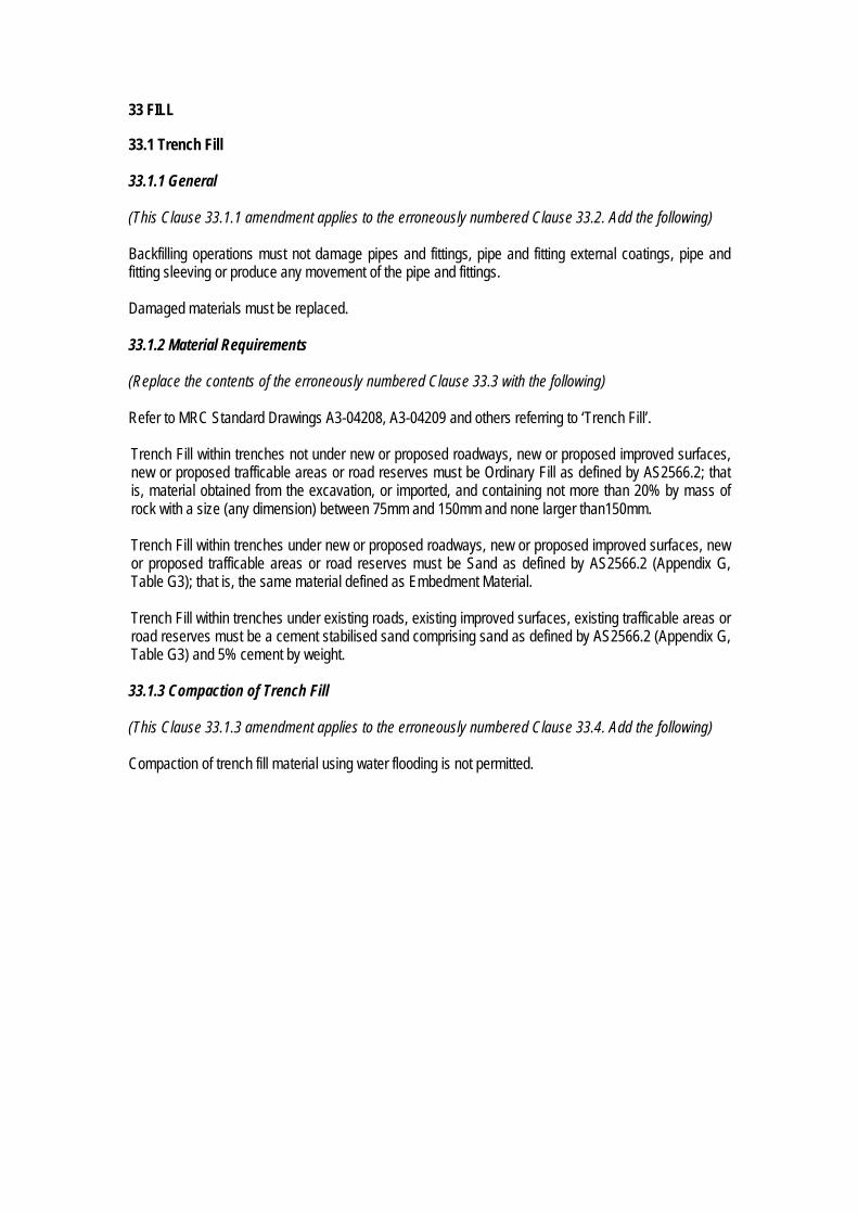
33 FILL 33.1 Trench Fill 33.1.1 General (This Clause 33.1.1 amendment applies to the erroneously numbered Clause 33.2. Add the following) Backfilling operations must not damage pipes and fittings, pipe and fitting external coatings, pipe and fitting sleeving or produce any movement of the pipe and fittings. Damaged materials must be replaced. 33.1.2 Material Requirements (Replace the contents of the erroneously numbered Clause 33.3 with the following) Refer to MRC Standard Drawings A3-04208, A3-04209 and others referring to ‘Trench Fill’. Trench Fill within trenches not under new or proposed roadways, new or proposed improved surfaces, new or proposed trafficable areas or road reserves must be Ordinary Fill as defined by AS2566.2; that is, material obtained from the excavation, or imported, and containing not more than 20% by mass of rock with a size (any dimension) between 75mm and 150mm and none larger than150mm. Trench Fill within trenches under new or proposed roadways, new or proposed improved surfaces, new or proposed trafficable areas or road reserves must be Sand as defined by AS2566.2 (Appendix G, Table G3); that is, the same material defined as Embedment Material. Trench Fill within trenches under existing roads, existing improved surfaces, existing trafficable areas or road reserves must be a cement stabilised sand comprising sand as defined by AS2566.2 (Appendix G, Table G3) and 5% cement by weight. 33.1.3 Compaction of Trench Fill (This Clause 33.1.3 amendment applies to the erroneously numbered Clause 33.4. Add the following) Compaction of trench fill material using water flooding is not permitted.

34 CONNECTION TO EXISTING GRAVITY SEWERS (Add the following) The Contractor shall carry out connection to existing sewers or sewerage infrastructure work unless;
(a) Council, in exceptional circumstances, decides to carry out the connection work (Exceptional circumstances may include connection to trunk mains, connections to complex systems and connection in areas with operational difficulties); or,
(b) the Developer requests that Council makes the connection on the understanding that the connection work will be carried out at Council’s convenience subject to its other work commitments; or,
(c) Council believes that the Contractor is not competent to make the connection; or, (d) the Contractor is not adhering to appropriate work practices.
If Council is to perform the connection;
a) All connection to existing sewers work undertaken by Council shall be at the Contractors expense.
b) A cost estimate of the works to be undertaken by Council will be provided to the Contractor and the connection will not be made until the payment is made to Council.
If the Contractor is to perform the connection;
a) The Contractor must obtain Council’s written approval to perform the works. b) A Council representative shall attend all works involved in connecting to existing sewers
(including plugging of live mains). c) The Contractor must follow Council directions. d) The Contractor remains responsible for all matters relating to the health and safety of the
Contractor, his employees and those affected by the works. e) All costs incurred by Council due to Council involvement in connection to existing sewers shall
be at the Contractors expense f) A cost estimate of the works to be undertaken by Council will be provided to the Contractor and
the connection must not commence until the payment is made to Council. A signed undertaking to pay the actual costs of the work must accompany the payment.
g) The Contractor must co-ordinate the work including notifications to Council, the Superintendent and the Developers representative.
h) The Contactor must provide Council, the Superintendent and the Developers representative with 5 working days notice of the work commencement date.
i) Council reserves the right to stop, or take over, works being undertaken by the Contractor, if, in Council’s opinion, the Contractor is incapable of completing the connection work in a reasonable time, Council’s infrastructure may be damaged or undue inconvenience to the public may be caused.
OR;
All connection to existing sewers or sewerage infrastructure must be undertaken by Council at the Contractors expense. A cost estimate of the works to be undertaken by Council will be provided to the Contractor and the connection will not be made until the payment is made to Council. An undertaking to pay the actual costs of the work, signed by the Contractor, must accompany the payment. The Contactor must provide Council, affected neighbouring residents and the Superintendent with 5 working days notice of the proposed connection commencement date.

Connections to existing pipes in-service shall be made at such times as will cause the least interference with the system operation.

35 RESTORATION 35.1 General (Add the following) References to ‘trench’ in this Clause 35 amendment shall also be read as ‘excavation’. 35.2 Pavements (Add the following) Final restoration of pavements must include the removal of temporary restoration works. Backfilling must restore full support to those structures or surfaces (including kerb and channel, road pavements or other improved surfaces) tunnelled under in lieu of trenching. 35.6 Provision for Settlement (Add the following) Further backfilling must be carried out, or the original backfill trimmed, at the end of the Defects Liability Period so that the surface of the completed trench matches design and/or adjacent finished surface levels. Subject to Council approval, and to the satisfaction of the Superintendent, material excavated from trenches and surplus to backfill requirements may be disposed of by spreading neatly in the vicinity of the trench in such a way as to avoid future erosion of the backfill and adjacent ground surfaces. Trench backfill finished surfaces must be levelled at the time of backfilling where the reasonable convenience of persons would be impacted upon if the backfill was left ‘high’. Subsequent settlement must be made good by additional filling at the time that the settlement becomes apparent. 35.7 Maintenance of Restored Surfaces (Add the following) Backfill and adjacent areas must be maintained throughout the Defects Liability Period.

36 ACCEPTANCE TESTING (‘Acceptance Testing’ shall be read as ‘Acceptance Inspections and Testing’)) 36.1 Pipelines This Clause 36.1 title is amended to ’36.1 General’. (Add the following) Construction of gravity sewers and maintenance structures, including acceptance testing of such, shall be in accordance with the requirements of WSA 02-2002 ‘Sewerage Code of Australia’. 36.3 Compaction Testing 36.3.4 Trench fill compaction testing 36.3.4.4 Frequency and location of tests (Add the following) The contractor shall perform compaction tests 75mm to 100mm below the top surface of the fill layer to be tested. Fill material within a trench traversing existing, proposed or new roads and road reserves must be tested for compaction in at least one location in each 300mm of fill material depth along the trench length within the road or road reserve extents. 36.4 Air Pressure and Vacuum Testing of Gravity Sewers 36.4.3 Testing of concrete emergency storage and maintenance structures 36.4.3.1 General (Add the following) Initial pressure testing and acceptance pressure testing requirements for emergency storage structures shall be determined by Council on a project specific basis given the variety of emergency storage structure types. The performance of initial pressure testing on emergency storage structures in the presence of the Superintendent and Council constitutes a WITNESS POINT. The Superintendent shall advise, at the time of notification by the Contractor, whether the option for the Superintendent to inspect the initial pressure testing is to be exercised. Council shall advise at the time of notification by the Superintendent whether the option for Council to inspect the initial pressure testing is to be exercised. The performance of acceptance pressure testing on emergency storage structures in the presence of the Superintendent and Council constitutes a HOLD POINT. The Superintendent’s and Council’s presence during acceptance pressure testing and sign-off of the test result certificates, as satisfactory, is required prior to the release of the hold point.

36.5 Hydrostatic Pressure Testing of Pressure Mains 36.5.1 General (Add the following) The performance of acceptance pressure testing in the presence of the Superintendent and Council constitutes a HOLD POINT. The Superintendent’s and Council’s presence during acceptance pressure testing and their sign-off of the test result certificates, as satisfactory, is required prior to the release of the Hold Point. Pressure mains shall be tested in sections approved by Council as soon as practicable after each section has been laid, jointed and backfilled, provided that:
(a) if so specified, or if the Contractor so desires, some or all of the pipe joints shall be left uncovered until the whole of the section has been successfully pressure tested; and,
(b) pressure testing shall not commence earlier than seven days after the last concrete thrust or anchor block in the test section has been cast; and,
(c) pressure testing shall not be carried out during wet weather unless approved by Council. A test section is defined as a length of pressure main which can be effectively isolated for testing, e.g. by means of main stop valves. The length of pressure main tested in one test event must not exceed 1000 metres. Pressure main of different diameter shall be tested separately and shall not be tested in the same test event. Any failure, defect, visible leakage or excessive leakage detected during the Defects Liability Period shall be rectified by the Contractor at the Contractor’s expense. 36.5.2 System test pressure (Replace the contents of Clause 32.5.2 with the following) The system test pressure shall be a minimum of 900kPa measured at the highest point in the test section. 36.5.3 Maximum allowable loss (Replace the contents of Clause 32.5.3 with the following) Calculate the Maximum Allowable Loss Rate (Q) as follows; Q = ((0.000532 + (C/ Lp)) x D x L x (H)0.5
Where: Q = Maximum Allowable Loss Rate (litres per hour) C = 0.0548 (for D.I. pipe) or 0.0568 (for PVC pipe) D = nominal diameter of pipe (mm) L = length of section tested (km) H = average test head (m) Lp = average pipe length (m) = L ÷ n n = total number of pipes + total number of fittings (in the section tested)
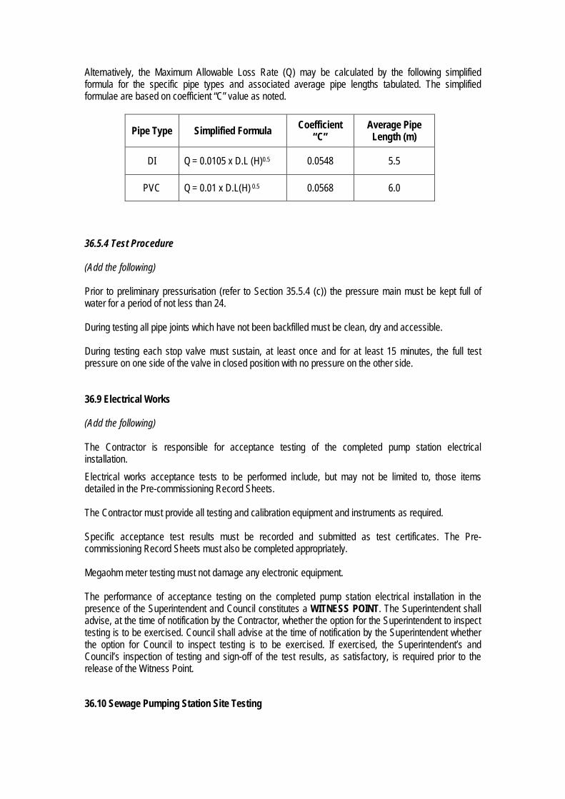
Alternatively, the Maximum Allowable Loss Rate (Q) may be calculated by the following simplified formula for the specific pipe types and associated average pipe lengths tabulated. The simplified formulae are based on coefficient “C” value as noted.
Pipe Type Simplified Formula Coefficient “C”
Average Pipe Length (m)
DI Q = 0.0105 x D.L (H)0.5 0.0548 5.5
PVC Q = 0.01 x D.L(H) 0.5 0.0568 6.0
36.5.4 Test Procedure (Add the following) Prior to preliminary pressurisation (refer to Section 35.5.4 (c)) the pressure main must be kept full of water for a period of not less than 24. During testing all pipe joints which have not been backfilled must be clean, dry and accessible. During testing each stop valve must sustain, at least once and for at least 15 minutes, the full test pressure on one side of the valve in closed position with no pressure on the other side. 36.9 Electrical Works (Add the following) The Contractor is responsible for acceptance testing of the completed pump station electrical installation. Electrical works acceptance tests to be performed include, but may not be limited to, those items detailed in the Pre-commissioning Record Sheets. The Contractor must provide all testing and calibration equipment and instruments as required. Specific acceptance test results must be recorded and submitted as test certificates. The Pre-commissioning Record Sheets must also be completed appropriately. Megaohm meter testing must not damage any electronic equipment. The performance of acceptance testing on the completed pump station electrical installation in the presence of the Superintendent and Council constitutes a WITNESS POINT. The Superintendent shall advise, at the time of notification by the Contractor, whether the option for the Superintendent to inspect testing is to be exercised. Council shall advise at the time of notification by the Superintendent whether the option for Council to inspect testing is to be exercised. If exercised, the Superintendent’s and Council’s inspection of testing and sign-off of the test results, as satisfactory, is required prior to the release of the Witness Point. 36.10 Sewage Pumping Station Site Testing

(This Clause 36.10 is an additional sub-clause to Clause 36 of WSA 04-2005) Sewage Pumping Station Site testing (Site Testing) must be performed once the works are substantially completed and the equipment is in a condition to be tested. Site testing must include, but not be limited to the following:-
a) Performance tests of the mechanical and electrical equipment b) Adjustments and setting of all field control and safety devices c) Noise level measurements d) Electrical and control tests as detailed below e) Functional check of all control and instrument loops and logic testing of circuitry and programs f) Verification of calibration of all flow meters g) Setting and calibration of all other instrumentation h) MEN Earthing: Conformation of effective earthing of exposed metal of electrical equipment. i) A static and dimensional inspection to establish that all items of equipment are complete and
the equipment is ready for no-load operation; j) No-load operation to demonstrate that all equipment functions successfully, both separately and
as components of integrated systems; k) Design load/acceptance operation to demonstrate that all equipment can successfully and
reliably operate under working conditions. l) checks and tests stipulated by those Australian Standards relevant to the works m) checks and tests required by the Electricity Supply Authority.
Submit a Site Testing Program to the Superintendent two (2) weeks prior to the commencement of any site testing. All testing equipment, labour and necessary facilities for all tests must be supplied by the Contractor. Site testing of all equipment must be supervised by the Contractor and representatives of the relevant sub-contractors. If it is not possible to activate any electrical protective equipment or device, use a simulate test to trigger a change of state in the RTU and observe control system functionality. Further to the requirements of clause 36.9 of WSA 04-2005-2.1, which details electrical works acceptance testing to be performed, further specific site tests must be performed in relation to all aspects of the sewage pumping station as detailed in the Pre-commissioning Record Sheets. Specific site test results must be recorded and submitted as test certificates. The Pre-commissioning Record Sheets must also be completed appropriately. The performance of the specific site tests on the sewage pumping station in the presence of the Superintendent and Council constitutes a WITNESS POINT. The Superintendent shall advise, at the time of notification by the Contractor, whether the option for the Superintendent to inspect testing is to be exercised. Council shall advise at the time of notification by the Superintendent whether the option for Council to inspect testing is to be exercised. If exercised, the Superintendent’s and Council’s inspection of testing and sign-off of the test results, as satisfactory, is required prior to the release of the Witness Point. 36.11 Detectable Marking Tape (This Clause 36.11 is an additional sub-clause to Clause 36 of WSA 04-2005) Demonstrate detection of buried detectable marking tape in the presence of the Superintendent following completion of trench and structure backfill. Demonstrate at the rate of one in seven sewer-sections/structures.

The performance of detection demonstrations in the presence of the Superintendent constitutes a HOLD POINT. The Superintendent’s presence during detection demonstrations and sign-off of the test results, as satisfactory, is required prior to the release of the hold point. The performance of detection demonstrations in the presence of the Council constitutes a WITNESS POINT. Council shall advise at the time of notification by the Superintendent whether the option for Council to inspect the detection demonstrations is to be exercised.

37 COMMISSIONING 37.1 General (Add the following) Field testing shall mean site testing. Tests and inspections shall comply with relevant Australian Standards. 37.2 Pumping Station 37.2.2 Pre-Commissioning (Add the following) Pre-commissioning is the preparation of plant or equipment so that it is in a safe and proper condition and ready for commissioning and operation. It includes all aspects of plant operation such as safety, electrical, mechanical and instrumentation. Pre-commissioning is the culmination of all works inspections and testing, all acceptance inspections and testing and all inspections and testing noted on the pre-commissioning record sheets. Submit a pre-commissioning programme to the Superintendent for review two (2) weeks prior to the commencement of any site testing. The pre-commissioning process shall include, but is not limited to:-
(a) Completion of all works inspections and testing (b) Completion of all acceptance inspections and testing (c) Completion of all inspections and testing (other than those conducted as part of ‘Acceptance
Inspecting and Testing’) as listed on the Pre-commissioning Record Sheets. (d) Completion of mechanical, electrical and control component testing (e) Completion of equipment and system operational tests (f) Submission of all inspection and testing results to the Superintendent (g) Submission of all Superintendent-verified inspection and testing results to Council (h) Submission of all manufacturer’s compliance certificates for items, materials and equipment
supplied, including, but not limited to, pipes, valves, pumps, flow-meters and electrical equipment, to the Superintendent
(i) Submission of all Superintendent-verified manufacturer’s compliance certificates to Council (j) Submission of all as-constructed information, including but not limited to drawings, to the
Superintendent (k) Submission of all Superintendent-verified as-constructed information, including but not limited
to drawings, to Council (l) Submission of the ‘Pump Data Record Sheet’ to the Superintendent (m) Submission of the Superintendent-verified ‘Pump Data Record Sheet’ to Council (n) Initial charges of lubricants to pump arrangements (o) Proving the installations functional aspects such as rotation direction checks, balancing and
vibration checks, temperature, pressure and flow measurements, control and protection equipment including adjustment of instrument set points and alarm settings and proving correct operation of alarms
(p) Proving the installations dimensional aspects such as assembly completeness, alignments and clearances

Notwithstanding the hold-point and witness-point requirements noted elsewhere, the presence of the Superintendent and Council, during the various inspections and tests that constitute the pre-commissioning process, constitutes as a minimum a WITNESS POINT. The Superintendent shall advise, at the time of notification by the Contractor, whether the option for the Superintendent to witness any of the various inspections and tests that constitute pre-commissioning is to be exercised. Council shall advise at the time of notification by the Superintendent whether the option for Council to witness any of the various inspections and tests that constitute pre-commissioning is to be exercised. If exercised, the Superintendent’s and Council’s sign-off of test results, as satisfactory, is required prior to the release of the Witness Point. Following completion of all inspections and tests, and other physical pre-commissioning process aspects, the submission of;
a) satisfactory inspection and test results (refer paragraph below; 3 copies), b) all as-constructed information (refer Clause 39), c) the ‘SPS Operations and Maintenance Manual’ (refer Clause 39.3; 3 hard copies and 1
electronic soft copy), d) the ‘Pump Data Record Sheet’ (refer Appendix B), and e) the Commissioning Programme (refer to Clause 37.2.3; 3 hard colour copies),
from the Contractor to the Superintendent, the Superintendents verification that the submitted information satisfies the construction specification requirements, and then submission of the verified information by the Superintendent to Council, constitutes a HOLD POINT. The submission as a whole will be referred to as the ‘Pre-commissioning Submission’. Inspection and test results to be submitted include, but are not limited to;
a) Works inspection and testing results (refer clause 20.9 (amended)) b) Acceptance inspection and testing results (refer clause 36 (amended)) c) Pre-commissioning Record Sheet inspection and testing results (refer Appendix A)
The basis of the inspection and test results submission is the works inspection record sheets, the works testing record sheets, the acceptance inspection record sheets, the acceptance testing record sheets, the ‘Pre-commissioning Record Sheets’ and any other record sheet required to adequately record all inspection results or test results not described on the record sheets noted here. Council’s review and acceptance of the Pre-commissioning Submission is required prior to the release of the Hold Point. Pumping station commissioning shall not commence until the Hold Point is released. 37.2.3 Commissioning (Add the following) Commissioning is the running of the plant and equipment to ensure flow through the pumping system, and carrying out any necessary inspections, tests and adjustments until the sewage pumping station is ready and suitable for normal starting and running under service conditions. A commissioning programme must be submitted to the Superintendent and Council for review (refer Clause 37.2.2). The Contractor must give the Superintendent a minimum of five (5) working days notice of the intention to commence commissioning and can only provide that notice after release by Council of the Hold Point stipulated in the Clause 37.2.2.

Commissioning inspections and tests must be carried out by qualified personnel. The commissioning process shall include, but is not limited to:-
(a) Completion of pump performance tests in accordance with the ‘Pump Performance Test Sheet’ (refer Appendix D)
(b) Completion of all inspections and tests noted on the ‘Commissioning Record Sheet’ (refer Appendix C)
The performance of commissioning inspections and tests in the presence of the Superintendent and Council constitutes a HOLD POINT. The Superintendent’s and Council’s presence during commissioning and their sign-off of the Record Sheets, as satisfactory, is required prior to the release of the Hold Point. Pump performance testing must demonstrate that;
(a) fixed-speed pumps operate at flow and head required under all operating conditions to achieve the performance requirements
(b) variable-speed pumps operate at flow and head required under all operating conditions over the entire range of operating speeds to achieve the performance requirements
Commissioning is not complete until the pump station has been run continually without any faults for a minimum of fifteen (15) days in accordance with required control and operation procedures. If during this period any mechanical or electrical equipment does not operate as specified then the commissioning must be repeated after rectification of defects. All rectification works and the cost of additional commissioning will be at the Developer’s expense. 37.2.4 Handover (Add the following) The sewage pumping station must be complete and be in working order, as demonstrated by the successful completion of the pre-commissioning and commissioning processes, before the works are accepted by Council either as ‘on-maintenance’ or as ‘practically complete’.
38 TOLERANCES ON AS-CONSTRUCTED WORK (Add the following) Construction of gravity sewers and maintenance structures, including as-constructed tolerances of such, shall be in accordance with the requirements of WSA 02-2002 ‘Sewerage Code of Australia’. Refer to Clause 23 of WSA 02. Road and hardstand construction tolerances are not specified by this document. 38.2 Vertical Tolerances 32.2.1 Sewers, pressure mains, structures, pumping stations, roads (Add the following) For pressure mains;
a) minimum depth of cover is as denoted on Council Standard Drawing A3-04172 ‘Pipe Installation – Support & Trench Fill – Pressure Mains ≤ DN300’, and
b) maximum depth of cover for pressure mains ≤ DN300 is 2500mm, and c) vertical tolerance from design is ±50mm

39 WORK AS-CONSTRUCTED DETAILS 39.1 General (Add the following) Refer to Council’s construction specification C101 ‘General’ and Council’s engineering design guideline D20 ‘Drawings and Documentation Guidelines’. Further to the requirements of C101 and D20, as-constructed Drawings must show;
1. sewage pumping station details 2. maintenance structure location (perpendicular distances to property boundaries), type, level 3. house connection branch location (distance to centre of downstream MH), type, depth to top-of-
riser 4. pipeline locations/alignments, size, type, levels and grades 5. easement extents
Structures represented on design drawings and removed during the works (including but not limited to pipe, fittings, pavements etc.) must not be represented on the as-constructed drawings. Structures represented on design drawings and made redundant during the works (including but not limited to pipe, fittings, pavements etc.) must be noted as ‘redundant’ on the as-constructed drawings. Areas of side-fill which contribute to the structural integrity of pipelines of a diameter greater than 225mm must be shown on the as-constructed drawings as areas not be disturbed without performance of an appropriate risk assessment. 39.3 Operations and Maintenance Manuals (This clause 39.3 is a new clause) Operations and Maintenance Manuals must be submitted in hard-copy (paper) form and in soft-copy (electronic pdf) form. All hard-copy pages and drawings shall be properly reinforced where attached to the binder. Operations and Maintenance Manuals shall contain at least the following information:
1. Cover page displaying; (a) Council issued SPS number and SPS name (b) SPS location (Street, Suburb)
2. Contents Page
3. Section containing;
(a) Constructors name, address and telephone numbers. (b) Principal’s Contract number and project description.
4. Section containing; (a) Pumping station general arrangement as-constructed drawings
5. Section relating to pumps (including motors) and containing;

(a) details and formatting in accordance with WSA 101-2008 ‘Industry standard for submersible
pumps for sewage pumping stations’, Appendix D ‘Documentation’. (b) Safe Work Procedures for all operating procedures and maintenance procedures
6. Section relating to valves and containing;
(a) dimensioned sectional arrangement drawings with associated parts and material list (b) Safe Work Procedures for all operating procedures and maintenance procedures
7. Section relating to Electrical Equipment and containing;
(a) Component-part-number list (b) Technical data sheets (c) Routine maintenance details & procedures – step-by-step procedures for preventative
maintenance work carried out at intervals of two (2) weeks or less (d) Periodic maintenance details & procedures – step-by-step procedures for preventative
maintenance work carried out at intervals in excess of two (2) weeks, including replacement of consumables
(e) Repair & Overhauling – step-by-step procedures for fault correction and for preventative maintenance, involving parts other than consumables. A list of any necessary special tools shall be included.
(f) Recommended spare parts list – illustrations and schedules for identification and specification of all items of equipment.
8. Section relating to Electrical Drawings and containing;
(a) Electrical-drawing index (b) Single-line diagram (c) Power-distribution schematic (d) Common-controls schematic (e) RTU-termination drawings (f) Equipment list (g) Cable schedule (h) Switchboard-label schedule (i) Site layout (with accurate as-constructed conduit paths noted) (j) Switchboard general arrangement (k) Switchboard construction details
9. Section relating to equipment warranty and containing all warranty information relating to;
(a) Pumps (b) Motors (c) Valves (d) Switchboards (e) Control equipment (f) Communications equipment (g) Other electrical equipment (h) Miscellaneous fittings, fixtures, materials and equipment

Appendix A
Pre-Commissioning Record Sheets

Pre-Commissioning Record Sheet Mechanical Installations
Job Name: Date:
Job Number: ITP Reference:
Description : Category :
Check Item Description: Status (Y/N/na)
Checked (Initial &
Date) Comments
1
Check that the installation of pump sets & associated pipe-work, pump pedestals, valves, fittings & gauges complies with approved design layouts & P&IDs ?
2 Static & Dimensional Check – all equipment is complete
3 Static & Dimensional Check – pipe alignments & clearances
4 Pump sets provided comply with WSA 101- 2008
5
Guide rails provided comply with WSA 101- 2008 – Clause 3.9.1. Guide rails & top guide rail mounting bracket constructed of 316 stainless steel.
6
Lifting chains comply with WSA 101 – 2008 – Clause 3.9.2. Lifting chains constructed of 316 stainless steel. Confirm lifting chains are coupled correctly to pump at nominated lifting points.
7
Pump mounting pedestal fitted to floor in accordance with Council specifications. Check all pedestal holding down bolts are fastened and tight. Pedestal holding down bolts 316 stainless steel minimum 20mm diameter. Pedestal grouting has been provided.
8 Visually check alignment of connections of pump to pedestal.
9 Pumps can be removed from the well using guide rails & no conflict occurs with pipe-work, fittings or well opening.
10 No rubbish at the bottom of the well which is likely to damage the Pump when it is started
11 All fasteners and mountings are tightened correctly
12
Pump set & motor labels have been provided as per WSA 101-2008. Details have been noted for inclusion in site documentation.
13 Confirm lubricant levels as per manufacturers requirements
14 Rotor mechanical freedom – manually turn to confirm

15
Confirm that vendor Factory Testing Certificates or Type Test Certificates and pump curves have been obtained (attach copy of pump curve to this ITP)?
16 Bump test pumps to confirm correct shaft direction of rotation
17 Operate pumps against closed discharge valve & confirm pump seal is effective & that no pipe-work leaks are detected
18
All valves operate from the closed to fully open position. All valves are right handed, easy to operate and have no sharp protrusions on Hand Wheels. Number of turns between fully open to closed to be noted & recorded in site documentation.
19 Confirm all valves seal when closed
20
Pressure gauges & associated process connection installed in valve chamber as per approved design. Pressure gauges ranged correctly for maximum discharge pressure registration.
21 Operate pumps & confirm balance/vibration levels are satisfactory
22 Pump well & confirm rising main is full by sighting 100% flow discharging at receiving manhole
23 Close line valve & open scour valve, confirm flow back into well with pumps operating
24 Open line valve (no pumps operating) & confirm rising main drains back into well
25 Open emergency pump valve with pumps operating & confirm discharge from camlock fitting
26 Design-load Operation performed – flow (calculated & flow meter), pressure, amps, kwh/1000lts.
General Comments
Representatives Date
Principal Contractor
Name
Signature
Superintendent
Name
Signature
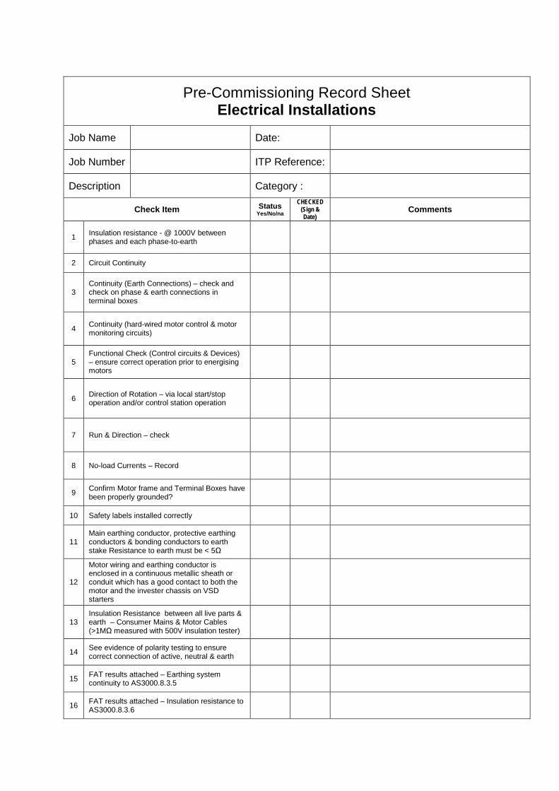
Pre-Commissioning Record Sheet Electrical Installations
Job Name Date:
Job Number ITP Reference:
Description Category :
Check Item Status Yes/No/na
CHECKED (Sign & Date)
Comments
1 Insulation resistance - @ 1000V between phases and each phase-to-earth
2 Circuit Continuity
3 Continuity (Earth Connections) – check and check on phase & earth connections in terminal boxes
4 Continuity (hard-wired motor control & motor monitoring circuits)
5 Functional Check (Control circuits & Devices) – ensure correct operation prior to energising motors
6 Direction of Rotation – via local start/stop operation and/or control station operation
7 Run & Direction – check
8 No-load Currents – Record
9 Confirm Motor frame and Terminal Boxes have been properly grounded?
10 Safety labels installed correctly
11 Main earthing conductor, protective earthing conductors & bonding conductors to earth stake Resistance to earth must be < 5Ω
12
Motor wiring and earthing conductor is enclosed in a continuous metallic sheath or conduit which has a good contact to both the motor and the invester chassis on VSD starters
13 Insulation Resistance between all live parts & earth – Consumer Mains & Motor Cables (>1MΩ measured with 500V insulation tester)
14 See evidence of polarity testing to ensure correct connection of active, neutral & earth
15 FAT results attached – Earthing system continuity to AS3000.8.3.5
16 FAT results attached – Insulation resistance to AS3000.8.3.6

17 FAT results attached – Polarity to AS3000.8.3.7
18 FAT results attached – Circuit connections to AS3000.8.3.8
19 FAT results attached – Impedance to AS30000.8.3.9
20 General inspection of electrical installation. Works are completed & ready for testing.
21 Confirm no installation damage has occurred to switchboard – dents, scratches etc.
22 All equipment checked against equipment schedules and marked up schedules adjusted as required
23 SCA rating plate complying with AS3439.1 has been fixed to indoor type SCA and all detail have been confirmed
24 Station identification labels mounted at top of each outer door on outdoor pump station SCA’s
25 Electrical signage installed as per AS3439 – Clause 5.2
26 KWH meter panels are wired to Supply Authority requirements
27 Switchboard orientation and fixing correct
28 Switchboard plinth and all gland plates sealed
29 All wiring holes are bushed
30 No sharp edges on metal work
31 All cables properly glanded at the switchboard
32 Weather seals fitted to all outer door openings and fixed securely
33 All locking bars on multi point lock systems are fixed securely into lock mechanism
34 Switchboard locks fitted – all operable
35
Adequate space provided around switchboards as per AS3000 – Clause 2.9.2.2. Clearance space does not include a step down in concrete FSL - trip hazard.
36 Consumers mains have been sized for all operational pump loads plus any auxiliary load. Submit all cable calculations
37 Consumers mains installation inspection – mechanical protection, location of underground cable & proximity of other services confirmed
38 All power & earthing cable terminations tested for tightness
39
Consumers mains conductor CSA, current carrying capacity, DC resistance - recorded. Primary (Ergon) protective device rating/characteristics – recorded. Insulation resistance test conducted at 500VDC, test result no less than 1.0Mohm.

40
Cables checked as per cable schedule. Derated Cables (0.6/1kV Cables) – check for compliance with AS3008.1.1. check cables are as per cable schedule
41 Cable Markers (0.6/1kV Cables) – check for correct identification as per drawings
42 Labels identifying all neutral connections located adjacent to neutral link
43 Electrical supply has been connected and energised.
44 Phase Rotation – Consumer Mains (L1, L2, L3) clockwise
45
Earth Electrode installed in specified connection box. Earth electrode diameter > 16mm & depth 2400mm.
46
Structure concrete reinforcing connected to main earth. Connection able to be separated from the main earth for testing.
47 Earth pit, main earth electrode and water service bond equipotential bonding installed & labelled as per AS 3000 Clause 5.5.1.3.
48 Main earth & equipotential earth resistance– complies with AS3000 & AS3017. Values no more than 0.5 ohm
49
Sub-circuit earthing to comply with AS3000 & AS3017. Fault loop impedance tests for each sub-circuit to be tested & results provided.
50
Sub-circuit insulation testing to be conducted & results provided. Insulation resistance test conducted at 500VDC, test result no less than 1.0Mohm.
51 Insulation Resistance (0.6/1kV Cables) – check with 1000V megaohm meter (phase-to-phase, phase-to-neutral, phase-to-earth)
52 Insulation Resistance (0.6/1kV Cables) – test all control cores in a cable, as a group, to earth - value not to exceed 1.0Mohm @ 500VDC
53 All labels fixed to insulating panels and enclosures are fixed with insulated bolts, nuts and fixings
54 Rating of all fuse elements is marked by label adjacent to the respective fuse
55 Termination numbers as per drawings
56 Confirm sufficient terminals installed to allow an individual terminal for every incoming field wire
57 All control wiring terminated with crimp lugs or crimp ferrules
58 Wire numbers as per drawings
59 Point-to-point checks conducted
60 All motor isolating switches are labelled
61 All motor isolating switches are pad-lockable in the off position

62 Fuses/circuit breaker settings correct as per drawings
63 Control switches & sequences operate as specified
64 Confirm that supply monitoring relay picks up (indicating correct supply phase sequence & voltage levels)
65 Trips tested
66 Control sequences – delay start etc
67
Pump detail and rating plate installed and all pump details engraved on the plate have been confirmed against pump manufacturers approved pump
68 Ratings for all motor starter equipment and ammeters checked against Specification and information from pump drive motor supplier
69
Shielded cable has been used on VSD starters. Shield terminated in EMC glands & terminals at both the VFD & motor as per manufacturers requirements.
70
Insulation test motor PU01 at 500V – motor isolate from starter circuitry (must be > 1.0 Mohm) Pump 1 - ____________ MΩ Pump 2 - ____________ MΩ Pump 3 - ____________ MΩ
71
Insulation test motor PU02 at 500V – motor isolate from starter circuitry (must be > 1.0 Mohm) Pump 1 - ____________ MΩ Pump 2 - ____________ MΩ Pump 3 - ____________ MΩ
72
Insulation test motor PU03 at 500V – motor isolate from starter circuitry (must be > 1.0 Mohm) Pump 1 - ____________ MΩ Pump 2 - ____________ MΩ Pump 3 - ____________ MΩ
73
Thermistor resistance T1 to T2 – measured with low voltage ohmmeter (must be between 150ohms - 600ohms) Pump 1 - ____________ Ω Pump 2 - ____________ Ω Pump 3 - ____________ Ω
74 Motor Thermistor resistance – measured with high impedance multi-meter (must be 150ohms < R < 600ohms)

75
Resistance between control cores S1 & S2 (non-Flgt pumps) – S1 disconnected (must be R>40 Kohm) Pump 1 - ____________ kΩ Pump 2 - ____________ kΩ Pump 3 - ____________ kΩ
76
Resistance between control cores S1 & Earth (Flygt pumps) – S1 disconnected (must be R>40 Kohm) Pump 1 - ____________ kΩ Pump 2 - ____________ kΩ Pump 3 - ____________ kΩ
77 Cable supports for the pump cables and level instrumentation are correctly located and properly fixed
78 Excess cable is supported clear of incoming sewer levels
79 No cable stocking has more than one cable installed in it
80 Motor cables are supported in the well so as to avoid damage when removing other pump
81 Motor cables in wells have minimal slack and do not present undue stress on motor cable glands
82 Appropriate lugs/pins fitted to all cables, and cables correctly identified at terminations
83
Motor terminations are in accordance with the manufacturers connection diagram. With star-delta starters, cable No. 1 is connected to the wiring from the overload.
84
Where parallel cables may be installed on site, provision has been made to ensure only one cable lug needs to be installed on each side of terminal lug
85 Bell all cores (0.6/1kV cables)
86 Point-to-point wiring checks performed
87 Voltage Variation – Phase-to-Phase & Phase-to-Earth (variation < 2%)
88 With Flygt pumps, ensure that an earth has been put on S2P
89 Seal Failure Probe resistance – test with high impedance multimeter (R>40,000ohms)
90 Level probe supported by suitable cable clamp
91 Level probe stilling pipe installed
92 Level probe is minimum 300 mm clear of all concrete and metal components & free of entanglement with other equipment
93 Level probe is mounted at correct level as per drawings

94 Analogue signals are calibrated (incl. Flow & pressure transmitters)
95 Analogue Spans – configured as per Council requirements (instrument, RTU, & SCADA) as per drawings
96 Level sensor ranged to include up to overflow level
97 Pressure transmitters ranged for maximum discharge pressure including shut head conditions & hydraulic transients
98 Pressure Switches – check settings as per drawings
99 Alarms transmit to centralised alarm monitoring point
100 Hydrostatic level sensor breather tube filter installed
101 Instrument mounting bracket installed
102 Float cables fitted with stainless steel thimbles
103 Instruments installed with sufficient spare cable to permit 1m adjustment & easy removal from the well for inspection
104 High level float activated & RTU input activation confirmed
105 Imminent Overflow level float activated & RTU input activation confirmed
106 Emergency back-up circuit activated & run timer calibrated for site conditions
107 Flow Meters – calibration verified
108 Generator socket inlet or junction box installed as per approved design
109 Emergency Start – alternator starts upon mains power failure if applicable
110 Generator inlet socket phase rotation configured (L1, L2, L3) clockwise
111 Generator connected to inlet socket & operation of “Mains/Generator” transfer switch confirmed
112
Noise levels (alternator operated on full station load) At 1m - ____________ dB At nearest property Boundary - ____________ dB
113 UPS Full Load Test – Output delivered for 8 hours duration
114 General Power – test all power outlets as per AS3000
115 General Power – test all RCD’s as per AS3000 & AS3017

116 Lighting – test switching circuits & light fitting operation.
117 Emergency Lighting – test
118 Smoke detectors – test
119 Arc flash certification – if applicable
120 Static & Dimensional Check – all equipment is complete & ready for no-load operation
121 No-load Operation performed – all equipment functions correctly
123 Design-load Operation performed – all equipment operates reliably under working conditions
124 Electrical Drawings (current) stored onsite
General Comments
Representatives Date
Principal Contractor
Name
Signature
Superintendent
Name
Signature
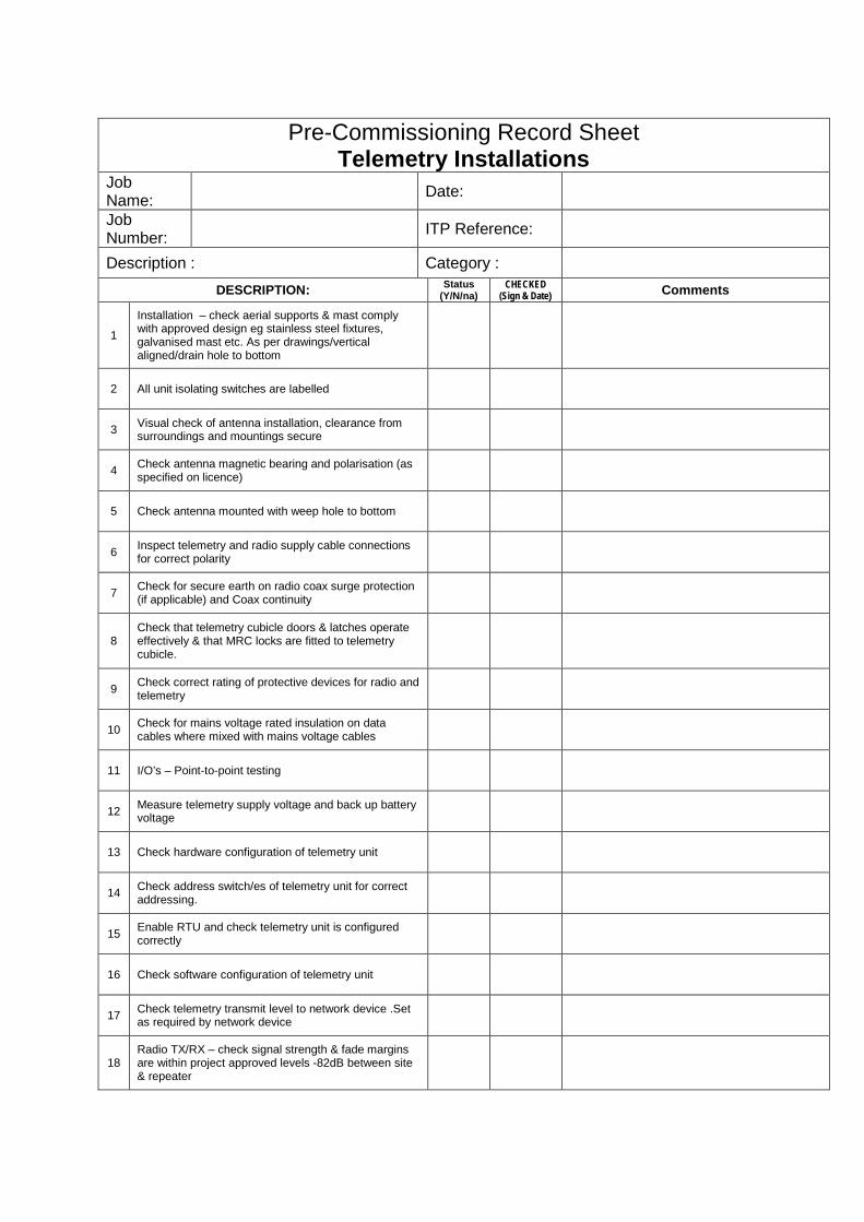
Pre-Commissioning Record Sheet Telemetry Installations
Job Name: Date: Job Number: ITP Reference:
Description : Category : DESCRIPTION: Status
(Y/N/na) CHECKED
(Sign & Date) Comments
1
Installation – check aerial supports & mast comply with approved design eg stainless steel fixtures, galvanised mast etc. As per drawings/vertical aligned/drain hole to bottom
2 All unit isolating switches are labelled
3 Visual check of antenna installation, clearance from surroundings and mountings secure
4 Check antenna magnetic bearing and polarisation (as specified on licence)
5 Check antenna mounted with weep hole to bottom
6 Inspect telemetry and radio supply cable connections for correct polarity
7 Check for secure earth on radio coax surge protection (if applicable) and Coax continuity
8 Check that telemetry cubicle doors & latches operate effectively & that MRC locks are fitted to telemetry cubicle.
9 Check correct rating of protective devices for radio and telemetry
10 Check for mains voltage rated insulation on data cables where mixed with mains voltage cables
11 I/O’s – Point-to-point testing
12 Measure telemetry supply voltage and back up battery voltage
13 Check hardware configuration of telemetry unit
14 Check address switch/es of telemetry unit for correct addressing.
15 Enable RTU and check telemetry unit is configured correctly
16 Check software configuration of telemetry unit
17 Check telemetry transmit level to network device .Set as required by network device
18 Radio TX/RX – check signal strength & fade margins are within project approved levels -82dB between site & repeater

19
Check telemetry receive level from network device, and set as required by the network device (or if not adjustable, ensure level is below telemetry threshold level)
20 Monitor telemetry messages for error
21 Monitor radio audio clarity and set audio control off or to min. volume
22 Signals transmit to centralised alarm monitoring point
23 I/O’s – Point-to-point testing, all signals register on scada & activate events & alarms as per approved design
24 RTU operates for 8 hours without mains power applied
25 Functional Operational check – all equipment as specified as per approved design
26 Operation – all hardware & software provided as per approved design
General Comments
Representatives Date
Principal Contractor
Name
Signature
Superintendent
Name
Signature
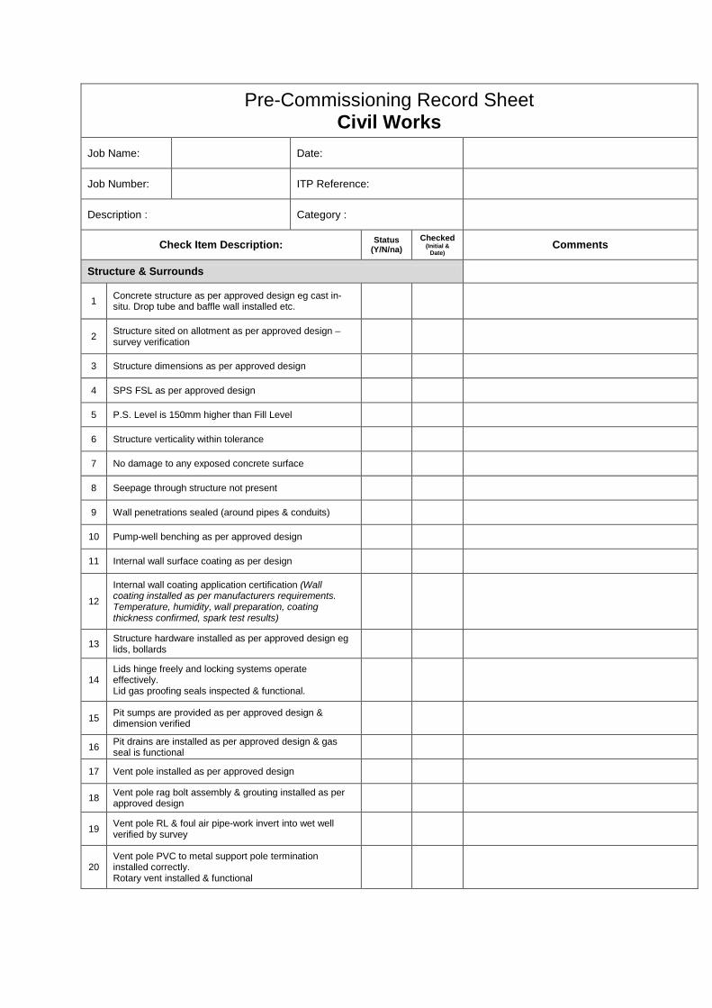
Pre-Commissioning Record Sheet Civil Works
Job Name: Date:
Job Number: ITP Reference:
Description : Category :
Check Item Description: Status (Y/N/na)
Checked (Initial &
Date) Comments
Structure & Surrounds
1 Concrete structure as per approved design eg cast in-situ. Drop tube and baffle wall installed etc.
2 Structure sited on allotment as per approved design – survey verification
3 Structure dimensions as per approved design
4 SPS FSL as per approved design
5 P.S. Level is 150mm higher than Fill Level
6 Structure verticality within tolerance
7 No damage to any exposed concrete surface
8 Seepage through structure not present
9 Wall penetrations sealed (around pipes & conduits)
10 Pump-well benching as per approved design
11 Internal wall surface coating as per design
12
Internal wall coating application certification (Wall coating installed as per manufacturers requirements. Temperature, humidity, wall preparation, coating thickness confirmed, spark test results)
13 Structure hardware installed as per approved design eg lids, bollards
14 Lids hinge freely and locking systems operate effectively. Lid gas proofing seals inspected & functional.
15 Pit sumps are provided as per approved design & dimension verified
16 Pit drains are installed as per approved design & gas seal is functional
17 Vent pole installed as per approved design
18 Vent pole rag bolt assembly & grouting installed as per approved design
19 Vent pole RL & foul air pipe-work invert into wet well verified by survey
20 Vent pole PVC to metal support pole termination installed correctly. Rotary vent installed & functional
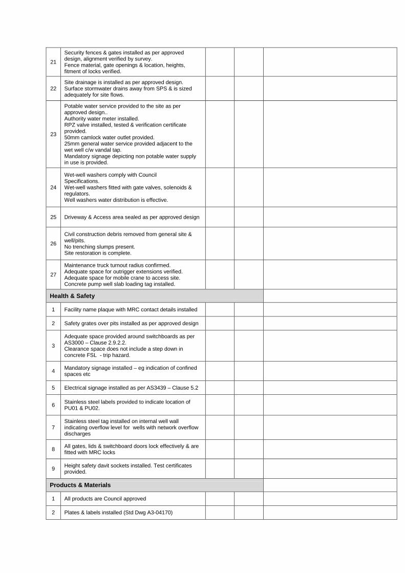
21
Security fences & gates installed as per approved design, alignment verified by survey. Fence material, gate openings & location, heights, fitment of locks verified.
22 Site drainage is installed as per approved design. Surface stormwater drains away from SPS & is sized adequately for site flows.
23
Potable water service provided to the site as per approved design.. Authority water meter installed. RPZ valve installed, tested & verification certificate provided. 50mm camlock water outlet provided. 25mm general water service provided adjacent to the wet well c/w vandal tap. Mandatory signage depicting non potable water supply in use is provided.
24
Wet-well washers comply with Council Specifications. Wet-well washers fitted with gate valves, solenoids & regulators. Well washers water distribution is effective.
25 Driveway & Access area sealed as per approved design
26
Civil construction debris removed from general site & well/pits. No trenching slumps present. Site restoration is complete.
27
Maintenance truck turnout radius confirmed. Adequate space for outrigger extensions verified. Adequate space for mobile crane to access site. Concrete pump well slab loading tag installed.
Health & Safety
1 Facility name plaque with MRC contact details installed
2 Safety grates over pits installed as per approved design
3
Adequate space provided around switchboards as per AS3000 – Clause 2.9.2.2. Clearance space does not include a step down in concrete FSL - trip hazard.
4 Mandatory signage installed – eg indication of confined spaces etc
5 Electrical signage installed as per AS3439 – Clause 5.2
6 Stainless steel labels provided to indicate location of PU01 & PU02.
7 Stainless steel tag installed on internal well wall indicating overflow level for wells with network overflow discharges
8 All gates, lids & switchboard doors lock effectively & are fitted with MRC locks
9 Height safety davit sockets installed. Test certificates provided.
Products & Materials
1 All products are Council approved
2 Plates & labels installed (Std Dwg A3-04170)

3 Covers & frames greased
4 Non hinged covers have lifting-lugs provided
Pipes & Fittings
1 Valves are anti-clockwise closing
2 Valve supports installed
3 Valve extension spindles installed
4 Pipe supports installed (to horizontal pipes) & are constructed of 316 stainless steel
5 Valve hand wheel installed
6 All pipework of correct diameter
7 Gate valves operate through full range & are in open position
8 Flap valve on valve chamber drain installed
9 Valve coatings as per Council requirements
10 Pipework coatings as per Council requirements
11 Inlet pipe dropper installed
12 Flange bolting system as per Council requirements
13 All valves pumps can be removed from well through opening
14 Flanged dismantling joints installed
15 All bolts are 316SS & Nuts are 304SS
16 Emergency pump-out pipework (incl. camlock arrangement) installed
17 SRM air releases/SRM scours installed
18 Clearances between pipe-work, valves & fitting to adjacent pit floor or well walls > 300mm
Overflow EROS
1 Overflow pit constructed as per approved design
2 Frog-flaps installed & operational (Pit & Outlet)
3 Pit covers are of specified class and material
4 Covers are installed as per approved design. Lids & hinges operate effectively & are locked.
5 Screens are installed as per approved design. Screen sizes & material of construction confirmed.
6 Overflow RL & well invert confirmed by survey
7 Overflow is accessible for maintenance
Acceptance Testing
1 Pump-well infiltration test – result complies
2 SRM testing – results comply

General Comments
Representatives Date
Principal Contractor
Name
Signature
Superintendent
Name
Signature

Appendix B
Pump Data Record Sheet

Pump Data Record Sheet Project Date
Job Number ITP Reference
Pump Data - General
Equipment Tag Number Serial Number
Equipment Location Weight (kg)
Hazardous Area Rating Design Flow (l/sec)
Manufacturer Design Head (m)
Pump Type Liquid Type
Rated Motor Power (kW) Paint Type
Pump Speed (rpm) Casing Material
Pump Data - Motor
Manufacturer Motor Speed (rpm)
Model Number Speed – if fixed (rpm)
Serial Number VSD Max. Speed (rpm)
Full Load Current (Amp) VSD Min. Speed (rpm)
Rated Volts (V) Gearbox
Weight (kg) Gearing Ratio
IP Rating Gearbox Weight (kg)
Comments

Appendix C
Commissioning Record Sheet
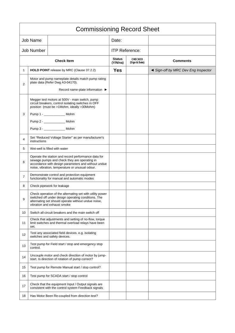
Commissioning Record Sheet Job Name Date:
Job Number ITP Reference:
Check Item Status (Y/N/na)
CHECKED (Sign & Date) Comments
1 HOLD POINT release by MRC (Clause 37.2.2) Yes Sign-off by MRC Dev Eng Inspector
2
Motor and pump nameplate details match pump rating plate data (Refer Dwg A3-04170).
Record name-plate information
3
Megger test motors at 500V - main switch, pump circuit breakers, control isolating switches in OFF position (must be >1Mohm, ideally >30Mohm) Pump 1 - ____________ Mohm Pump 2 - ____________ Mohm Pump 3 - ____________ Mohm
4 Set “Reduced Voltage Starter” as per manufacturer's instructions
5 Wet-well is filled with water
6
Operate the station and record performance data for sewage pumps and check they are operating in accordance with design parameters and without undue noise, vibration, temperature or unusual odour.
7 Demonstrate control and protection equipment functionality for manual and automatic modes
8 Check pipework for leakage
9
Check operation of the alternating set with utility power switched off under design operating conditions. The alternating set should operate without undue noise, vibration and exhaust smoke
10 Switch all circuit breakers and the main switch off
11 Check that adjustments and setting of no-flow, torque limit switches and thermal overload relays have been set.
12 Test any associated field devices. e.g. isolating switches and safety devices.
13 Test pump for Field start / stop and emergency stop control.
14 Uncouple motor and check direction of motor by jump-start. Is direction of rotation of pump correct?
15 Test pump for Remote Manual start / stop control?
16 Test pump for SCADA start / stop control
17 Check that the equipment Input / Output signals are consistent with the control system Feedback signals
18 Has Motor Been Re-coupled from direction test?

19 Have all dry-commissioning checks been signed of as per ITP?
20 Is there any leakage in the system?
21 Do up stream and downstream pressure gauges read the same?
22
Thermistor resistance T1 to T2 – measured with low voltage ohmmeter (must be 150ohms < R < 600ohms) Pump 1 - ____________ ohm Pump 2 - ____________ ohm Pump 3 - ____________ ohm
23 Motor Thermistor resistance – measured with high impedance multi-meter (must be 150ohms < R < 600ohms)
24
Resistance between control cores S1 & S2 (non-Flgt pumps) – S1 disconnected (must be R>40 Kohm) Pump 1 - ____________ Kohm Pump 2 - ____________ Kohm Pump 3 - ____________ Kohm
25
Resistance between control cores S1 & Earth (Flygt pumps) – S1 disconnected (must be R>40 Kohm) Pump 1 - ____________ Kohm Pump 2 - ____________ Kohm Pump 3 - ____________ Kohm
26 Is there any leakage in the system?
27 Does equipment fulfil its designed function under Wet-commissioning? (Delivers design flow rates, current draw etc.)
28
Is equipment deemed ready for Process Commissioning / demonstration? (e.g. can be operated under Remote Manual control for a process cycle without tripping alarms)
29 Check pump type (brand, pole)
30 Wet-well mechanical installation (pipework & fittings) –material type, valve types, operational check
31 Valve Pit mechanical installation (pipework & fittings) –material type, valve types, operational check
32 Pump-out mechanical installation (pipework & fittings) – type material, valve types, operational check
33 Overflow pit mechanical installation (pipework, screens & fittings) – material type, valve types, operational check
34 Perform Performance Test (complete ‘Pump Performance Test’ sheet)
35 Operate bypass system (SRM closed)
36 Operate Mobile Pump Connection arrangement
37 Vent pole is correct height
General Comments
Commissioning Representatives Date
Principal Contractor
Name
Signature
Superintendent
Name
Signature
MRC Dev Eng Inspector
Name
Signature

Appendix D
Pump Performance Test Sheet

Pump Performance Test Record Sheet
P&ID No.: Job Name: Location: Job No: Date : ITP No:
Description
Current
Rated Motor
Current
Current-
draw acceptance (1-2)/2<10%
Flow Measurement
Flow rate
Vibration -visual observation
Surface area of Wet Well
Water Depth At START
Water Depth at STOP
Pumped Flow 4x(5-6)x1000
Duration of Test
Design (Units)
Measured (Units)
7/8
Amp. Amp. Y/N m2 m m L S L/sec L/sec Normal/Abnormal (1) (2) (3) (4) (5) (6) (7) (8) (9) (10) (11)
Pump No. (Tag. No.):
Test 1
Test 2
Test 3
Comments:
Notes: 1 Pump curves and works tests results must be available before site test 2 Site test is not intended to reproduce pump curve, rather check if the pump can deliver adequate head under certain range of flow specified in designed by means of pump curve Witnessed by:____________________________ (Council Representative Signed: Dated:
Witnessed by: (Contractor’s Representative) Signed: Dated:
Witnessed by: (Supervising Engineer) Signed: Dated:
