butterfly valve model 45 - flomatic · pdf filestandard nbr (bunan)(other materials ......
TRANSCRIPT
Model 45 Butterfly Valve
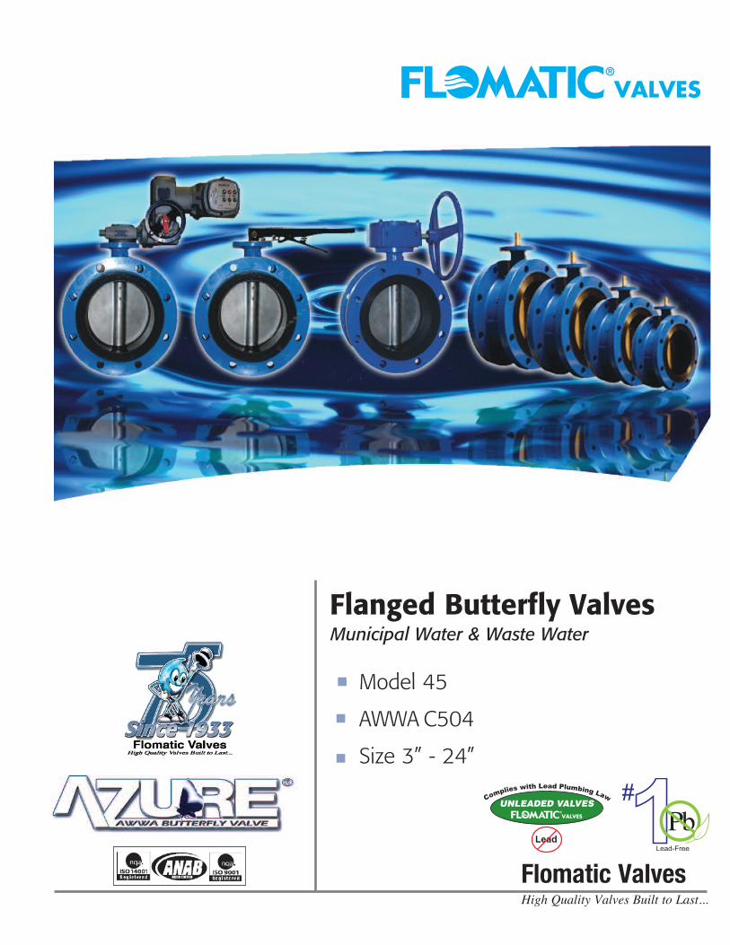
Flanged Butterfly ValvesMunicipal Water & Waste Water
Model 45
AWWA C504
Size 3” - 24”
Flomatic Corporation 15 Pruyn’s Island Drive
Glens Falls, NY 12801-4421
Telephone: 1-(800)-833-2040 Direct Telephone: 1-(518)-761-9797
Fax: 1-(800)-314-3155 Direct Fax: 1-(518)-761-9798
www.flomatic.com
High Quality Valves Built to Last...Flomatic Valves
© Copyright 2012 by Flomatic #YAzure Rev. 4/12
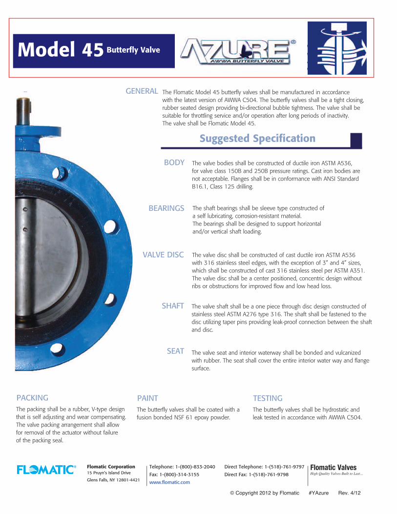
The Flomatic Model 45 butterfly valves shall be manufactured in accordance with the latest version of AWWA C504. The butterfly valves shall be a tight closing,rubber seated design providing bi-directional bubble tightness. The valve shall besuitable for throttling service and/or operation after long periods of inactivity. The valve shall be Flomatic Model 45.
GENERAL
The valve bodies shall be constructed of ductile iron ASTM A536,for valve class 150B and 250B pressure ratings. Cast iron bodies are not acceptable. Flanges shall be in conformance with ANSI Standard B16.1, Class 125 drilling.
BODY
Suggested Specification
The shaft bearings shall be sleeve type constructed ofa self lubricating, corrosion-resistant material.The bearings shall be designed to support horizontaland/or vertical shaft loading.
BEARINGS
VALVE DISC The valve disc shall be constructed of cast ductile iron ASTM A536with 316 stainless steel edges, with the exception of 3” and 4” sizes,which shall be constructed of cast 316 stainless steel per ASTM A351.The valve disc shall be a center positioned, concentric design withoutribs or obstructions for improved flow and low head loss.
The valve shaft shall be a one piece through disc design constructed ofstainless steel ASTM A276 type 316. The shaft shall be fastened to thedisc utilizing taper pins providing leak-proof connection between the shaftand disc.
SHAFT
The valve seat and interior waterway shall be bonded and vulcanizedwith rubber. The seat shall cover the entire interior water way and flangesurface.
SEAT
PACKINGThe packing shall be a rubber, V-type designthat is self adjusting and wear compensating.The valve packing arrangement shall allowfor removal of the actuator without failureof the packing seal.
PAINTThe butterfly valves shall be coated with afusion bonded NSF 61 epoxy powder.
TESTINGThe butterfly valves shall be hydrostatic andleak tested in accordance with AWWA C504.
UNLEADED VALVES
Flomatic ValvesHigh Quality Valves Built to Last...
* With Gear Operator, bare stem add B after part #
Contact our factory for larger models or other types of butterfly valves.
The
Dim
ensi
ons
The
Feat
ures
and
Ben
efit
s
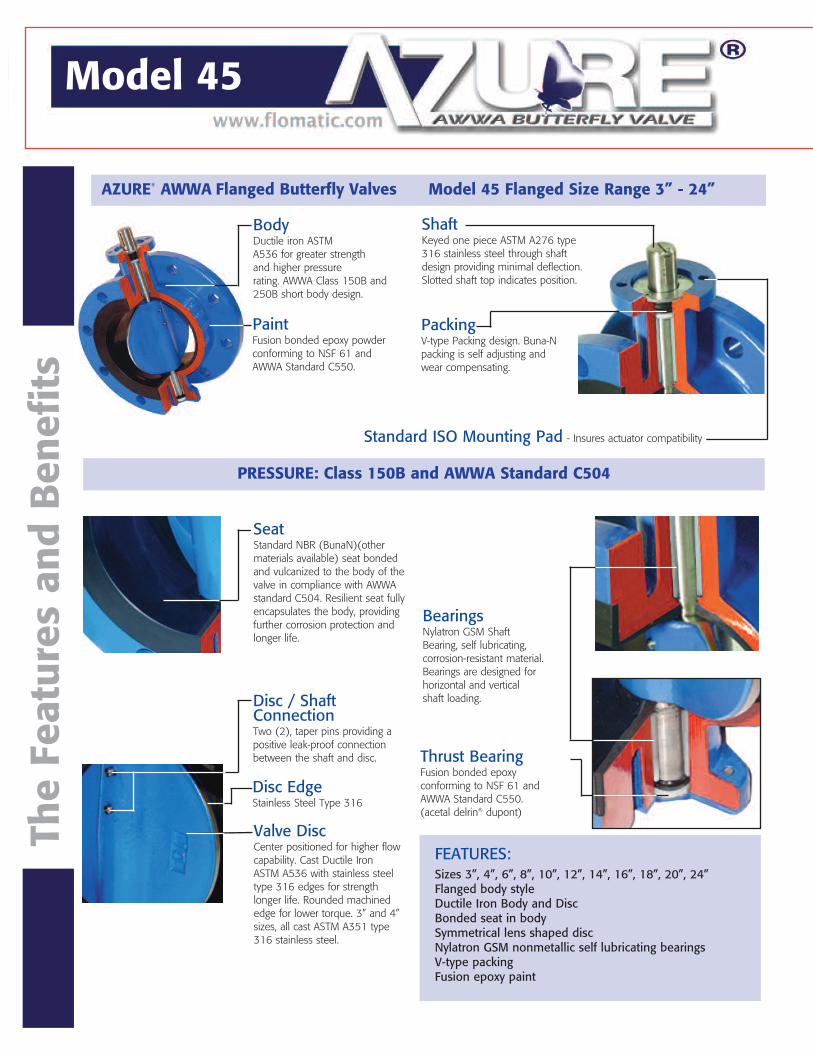
AZURE® AWWA Flanged Butterfly Valves Model 45 Flanged Size Range 3” - 24”
PRESSURE: Class 150B and AWWA Standard C504
BodyDuctile iron ASTM A536 for greater strength and higher pressure rating. AWWA Class 150B and250B short body design.
PaintFusion bonded epoxy powderconforming to NSF 61 and AWWA Standard C550.
ShaftKeyed one piece ASTM A276 type316 stainless steel through shaftdesign providing minimal deflection.Slotted shaft top indicates position.
PackingV-type Packing design. Buna-Npacking is self adjusting and wear compensating.
Standard ISO Mounting Pad - Insures actuator compatibility
Seat Standard NBR (BunaN)(other materials available) seat bondedand vulcanized to the body of thevalve in compliance with AWWAstandard C504. Resilient seat fullyencapsulates the body, providingfurther corrosion protection andlonger life.
Bearings Nylatron GSM Shaft Bearing, self lubricating,corrosion-resistant material.Bearings are designed forhorizontal and verticalshaft loading.
Thrust Bearing Fusion bonded epoxy conforming to NSF 61 andAWWA Standard C550.(acetal delrin® dupont)
Disc / ShaftConnection Two (2), taper pins providing apositive leak-proof connectionbetween the shaft and disc.
Disc Edge Stainless Steel Type 316
Valve Disc Center positioned for higher flowcapability. Cast Ductile IronASTM A536 with stainless steeltype 316 edges for strengthlonger life. Rounded machinededge for lower torque. 3” and 4”sizes, all cast ASTM A351 type316 stainless steel.
FEATURES:Sizes 3”, 4”, 6”, 8”, 10”, 12”, 14”, 16”, 18”, 20”, 24”Flanged body styleDuctile Iron Body and DiscBonded seat in bodySymmetrical lens shaped discNylatron GSM nonmetallic self lubricating bearingsV-type packingFusion epoxy paint
Model 45 Model 45
NOM VALVE SIZE
PART NUMBER
A B C D E F G H J K L M N P Q R S TWEIGH
T (LBS.)
3" 450100060 5.16 3.74 5.00 3.10 7.50 6.00 (4) 3/4" .94 15.00 7.88 6.13 1.75 5.75 .50 .13 1.20 .39 2.76 43
4" 450100070 5.91 4.49 5.00 4.09 9.00 7.50 (8) 3/4" .94 14.61 8.90 6.85 1.77 5.75 .63 .13 1.13 .39 2.76 54
6" 450000090 7.09 5.47 5.00 6.14 11.00 9.50 (8) 7/8" 1.00 17.09 8.90 6.85 1.77 5.75 1.00 .24 1.23 .39 2.76 74
8" 450000100 8.27 6.89 6.00 8.00 13.5011.75 (8) 7/8" 1.13 22.56 12.32 9.33 2.48 11.31 1.13 .32 2.00 .46 4.02 134
10" 450000110 9.69 8.00 8.00 9.88 16.0014.25 (12) 1" 1.18 25.24 12.32 9.33 2.48 11.31 1.38 .39 2.00 .46 4.02 188
12" 45000012010.87 9.53 8.00 11.8919.0017.00 (12) 1" 1.25 27.36 12.09 8.86 3.15 11.31 1.50 .39 2.09 .55 4.92 261
14" 45000014012.9110.08 8.00 14.0020.9818.74(12) 1-1/8" 1.38 30.59 12.09 8.86 3.15 11.31 1.50 .39 2.09 .55 4.92 380
16" 45000016014.7611.81 8.00 16.0023.5021.24(16) 1-1/8" 1.44 37.01 16.6111.50 4.72 15.50 2.00 .63 3.00 .70 5.51 414
18" 45000018015.9412.60 8.00 18.0025.0022.76(16) 1-1/4" 1.56 38.98 16.6111.50 4.72 15.50 2.00 .63 3.00 .70 5.51 532
20" 45000020017.6413.98 8.00 20.0027.5225.00(20) 1-1/4" 1.69 40.31 18.8213.44 4.78 15.50 2.13 .63 3.64 .87 6.50 653
24" 45000024020.3917.52 8.00 24.0032.0129.51(20) 1-3/8" 1.88 46.61 18.8213.44 4.78 15.50 2.25 .72 4.50 .87 6.50 739
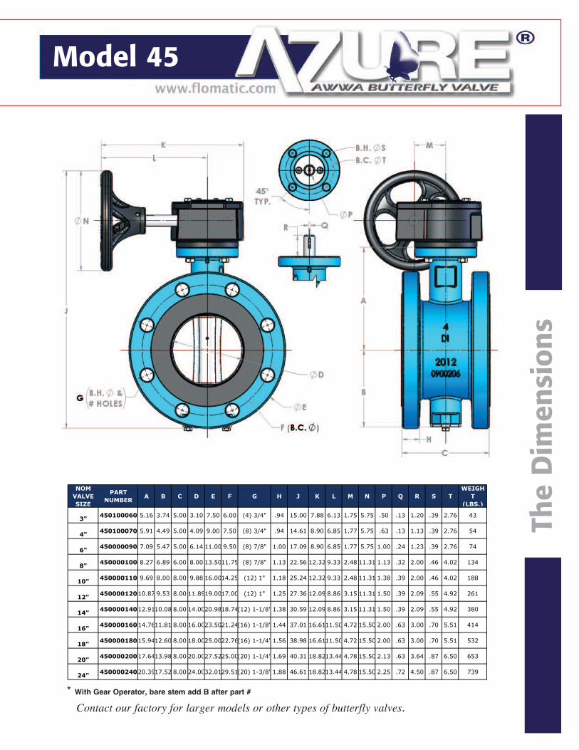
* With Gear Operator, bare stem add B after part #
Contact our factory for larger models or other types of butterfly valves.
The
Dim
ensi
ons
The
Feat
ures
and
Ben
efit
s
AZURE® AWWA Flanged Butterfly Valves Model 45 Flanged Size Range 3” - 24”
PRESSURE: Class 150B and AWWA Standard C504
BodyDuctile iron ASTM A536 for greater strength and higher pressure rating. AWWA Class 150B and250B short body design.
PaintFusion bonded epoxy powderconforming to NSF 61 and AWWA Standard C550.
ShaftKeyed one piece ASTM A276 type316 stainless steel through shaftdesign providing minimal deflection.Slotted shaft top indicates position.
PackingV-type Packing design. Buna-Npacking is self adjusting and wear compensating.
Standard ISO Mounting Pad - Insures actuator compatibility
Seat Standard NBR (BunaN)(other materials available) seat bondedand vulcanized to the body of thevalve in compliance with AWWAstandard C504. Resilient seat fullyencapsulates the body, providingfurther corrosion protection andlonger life.
Bearings Nylatron GSM Shaft Bearing, self lubricating,corrosion-resistant material.Bearings are designed forhorizontal and verticalshaft loading.
Thrust Bearing Fusion bonded epoxy conforming to NSF 61 andAWWA Standard C550.(acetal delrin® dupont)
Disc / ShaftConnection Two (2), taper pins providing apositive leak-proof connectionbetween the shaft and disc.
Disc Edge Stainless Steel Type 316
Valve Disc Center positioned for higher flowcapability. Cast Ductile IronASTM A536 with stainless steeltype 316 edges for strengthlonger life. Rounded machinededge for lower torque. 3” and 4”sizes, all cast ASTM A351 type316 stainless steel.
FEATURES:Sizes 3”, 4”, 6”, 8”, 10”, 12”, 14”, 16”, 18”, 20”, 24”Flanged body styleDuctile Iron Body and DiscBonded seat in bodySymmetrical lens shaped discNylatron GSM nonmetallic self lubricating bearingsV-type packingFusion epoxy paint
Model 45 Model 45
NOM VALVE SIZE
PART NUMBER
A B C D E F G H J K L M N P Q R S TWEIGH
T (LBS.)
3" 450100060 5.16 3.74 5.00 3.10 7.50 6.00 (4) 3/4" .94 15.00 7.88 6.13 1.75 5.75 .50 .13 1.20 .39 2.76 43
4" 450100070 5.91 4.49 5.00 4.09 9.00 7.50 (8) 3/4" .94 14.61 8.90 6.85 1.77 5.75 .63 .13 1.13 .39 2.76 54
6" 450000090 7.09 5.47 5.00 6.14 11.00 9.50 (8) 7/8" 1.00 17.09 8.90 6.85 1.77 5.75 1.00 .24 1.23 .39 2.76 74
8" 450000100 8.27 6.89 6.00 8.00 13.5011.75 (8) 7/8" 1.13 22.56 12.32 9.33 2.48 11.31 1.13 .32 2.00 .46 4.02 134
10" 450000110 9.69 8.00 8.00 9.88 16.0014.25 (12) 1" 1.18 25.24 12.32 9.33 2.48 11.31 1.38 .39 2.00 .46 4.02 188
12" 45000012010.87 9.53 8.00 11.8919.0017.00 (12) 1" 1.25 27.36 12.09 8.86 3.15 11.31 1.50 .39 2.09 .55 4.92 261
14" 45000014012.9110.08 8.00 14.0020.9818.74(12) 1-1/8" 1.38 30.59 12.09 8.86 3.15 11.31 1.50 .39 2.09 .55 4.92 380
16" 45000016014.7611.81 8.00 16.0023.5021.24(16) 1-1/8" 1.44 37.01 16.6111.50 4.72 15.50 2.00 .63 3.00 .70 5.51 414
18" 45000018015.9412.60 8.00 18.0025.0022.76(16) 1-1/4" 1.56 38.98 16.6111.50 4.72 15.50 2.00 .63 3.00 .70 5.51 532
20" 45000020017.6413.98 8.00 20.0027.5225.00(20) 1-1/4" 1.69 40.31 18.8213.44 4.78 15.50 2.13 .63 3.64 .87 6.50 653
24" 45000024020.3917.52 8.00 24.0032.0129.51(20) 1-3/8" 1.88 46.61 18.8213.44 4.78 15.50 2.25 .72 4.50 .87 6.50 739
Model 45 Butterfly Valve
Flanged Butterfly ValvesMunicipal Water & Waste Water
Model 45
AWWA C504
Size 3” - 24”
Flomatic Corporation 15 Pruyn’s Island Drive
Glens Falls, NY 12801-4421
Telephone: 1-(800)-833-2040 Direct Telephone: 1-(518)-761-9797
Fax: 1-(800)-314-3155 Direct Fax: 1-(518)-761-9798
www.flomatic.com
High Quality Valves Built to Last...Flomatic Valves
© Copyright 2012 by Flomatic #YAzure Rev. 4/12
The Flomatic Model 45 butterfly valves shall be manufactured in accordance with the latest version of AWWA C504. The butterfly valves shall be a tight closing,rubber seated design providing bi-directional bubble tightness. The valve shall besuitable for throttling service and/or operation after long periods of inactivity. The valve shall be Flomatic Model 45.
GENERAL
The valve bodies shall be constructed of ductile iron ASTM A536,for valve class 150B and 250B pressure ratings. Cast iron bodies are not acceptable. Flanges shall be in conformance with ANSI Standard B16.1, Class 125 drilling.
BODY
Suggested Specification
The shaft bearings shall be sleeve type constructed ofa self lubricating, corrosion-resistant material.The bearings shall be designed to support horizontaland/or vertical shaft loading.
BEARINGS
VALVE DISC The valve disc shall be constructed of cast ductile iron ASTM A536with 316 stainless steel edges, with the exception of 3” and 4” sizes,which shall be constructed of cast 316 stainless steel per ASTM A351.The valve disc shall be a center positioned, concentric design withoutribs or obstructions for improved flow and low head loss.
The valve shaft shall be a one piece through disc design constructed ofstainless steel ASTM A276 type 316. The shaft shall be fastened to thedisc utilizing taper pins providing leak-proof connection between the shaftand disc.
SHAFT
The valve seat and interior waterway shall be bonded and vulcanizedwith rubber. The seat shall cover the entire interior water way and flangesurface.
SEAT
PACKINGThe packing shall be a rubber, V-type designthat is self adjusting and wear compensating.The valve packing arrangement shall allowfor removal of the actuator without failureof the packing seal.
PAINTThe butterfly valves shall be coated with afusion bonded NSF 61 epoxy powder.
TESTINGThe butterfly valves shall be hydrostatic andleak tested in accordance with AWWA C504.
UNLEADED VALVES
Flomatic ValvesHigh Quality Valves Built to Last...