bulletin 100 iec contactors - search knowledgebase 100 iec contactors 3-7 product selection,...
TRANSCRIPT
Bulletin 100IEC Contactors
3-5
3
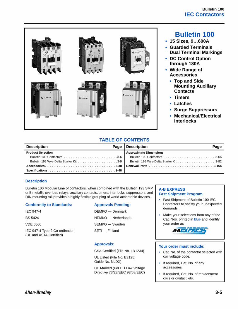
Bulletin 100• 15 Sizes, 9…600A• Guarded Terminals
Dual Terminal Markings• DC Control Option
through 180A• Wide Range of
Accessories• Top and Side
Mounting AuxiliaryContacts
• Timers• Latches• Surge Suppressors• Mechanical/Electrical
Interlocks
TABLE OF CONTENTSDescription Page Description PageProduct Selection
Bulletin 100 Contactors . . . . . . . . . . . . . . . . . . . . . . . . . . . . . . . 3-6Bulletin 199 Wye-Delta Starter Kit . . . . . . . . . . . . . . . . . . . . . . . 3-9
Accessories . . . . . . . . . . . . . . . . . . . . . . . . . . . . . . . . . . . . . . . . . 3-38Specifications . . . . . . . . . . . . . . . . . . . . . . . . . . . . . . . . . . . . . . . 3-48
Approximate DimensionsBulletin 100 Contactors . . . . . . . . . . . . . . . . . . . . . . . . . . . . . . 3-66Bulletin 199 Wye-Delta Starter Kit. . . . . . . . . . . . . . . . . . . . . . 3-82
Renewal Parts . . . . . . . . . . . . . . . . . . . . . . . . . . . . . . . . . . . . . 3-154
Description
Bulletin 100 Modular Line of contactors, when combined with the Bulletin 193 SMPor Bimetallic overload relays, auxiliary contacts, timers, interlocks, suppressors, andDIN mounting rail provides a highly flexible grouping of world acceptable devices.
A-B EXPRESSFast Shipment Program• Fast Shipment of Bulletin 100 IEC
Contactors to satisfy your unexpecteddemands.
• Make your selections from any of theCat. Nos. printed in blue and identifyyour order as
Conformity to Standards: Approvals Pending:
IEC 947-4 DEMKO — Denmark
BS 5424 NEMKO — Netherlands
VDE 0660 SEMKO — Sweden
IEC 947-4 Type 2 Co-ordination(UL and ASTA Certified)
SETI — Finland
Approvals:Your order must include:• Cat. No. of the contactor selected with
coil voltage code.
• If required, Cat. No. of anyaccessories.
• If required, Cat. No. of replacementcoils or contact kits.
CSA Certified (File No. LR1234)
UL Listed (File No. E3125;Guide No. NLDX)
CE Marked (Per EU Low VoltageDirective 73/23/EEC 93/68/EEC)
Bulletin 100IEC Contactors
3-6
Product Selection
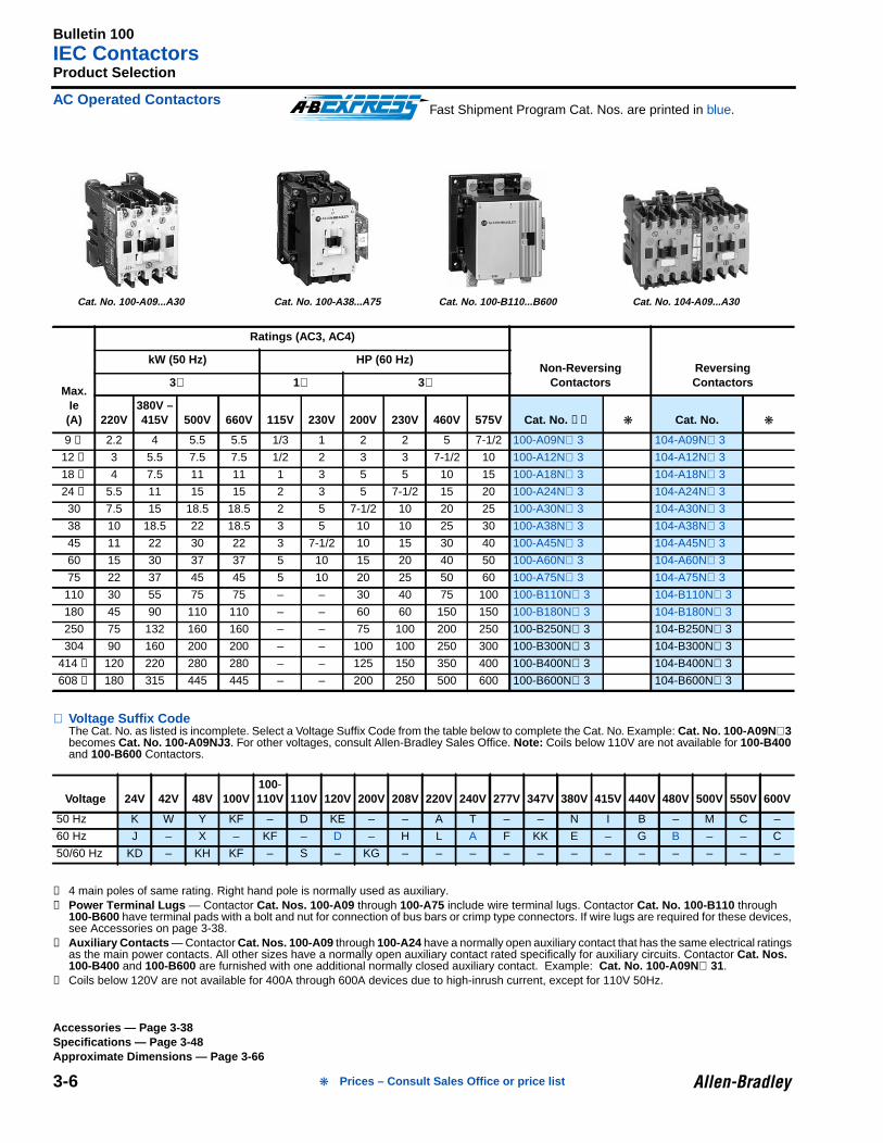
AC Operated Contactors
⊗ Voltage Suffix CodeThe Cat. No. as listed is incomplete. Select a Voltage Suffix Code from the table below to complete the Cat. No. Example: Cat. No. 100-A09N ⊗3becomes Cat. No. 100-A09NJ3 . For other voltages, consult Allen-Bradley Sales Office. Note: Coils below 110V are not available for 100-B400and 100-B600 Contactors.
➊ 4 main poles of same rating. Right hand pole is normally used as auxiliary.➋ Power Terminal Lugs — Contactor Cat. Nos. 100-A09 through 100-A75 include wire terminal lugs. Contactor Cat. No. 100-B110 through
100-B600 have terminal pads with a bolt and nut for connection of bus bars or crimp type connectors. If wire lugs are required for these devices,see Accessories on page 3-38.
➌ Auxiliary Contacts — Contactor Cat. Nos. 100-A09 through 100-A24 have a normally open auxiliary contact that has the same electrical ratingsas the main power contacts. All other sizes have a normally open auxiliary contact rated specifically for auxiliary circuits. Contactor Cat. Nos.100-B400 and 100-B600 are furnished with one additional normally closed auxiliary contact. Example: Cat. No. 100-A09N ⊗ 31.
➍ Coils below 120V are not available for 400A through 600A devices due to high-inrush current, except for 110V 50Hz.
Max.Ie(A)
Ratings (AC3, AC4)
Non-ReversingContactors
ReversingContactors
kW (50 Hz) HP (60 Hz)
3∅ 1∅ 3∅
220V380V –415V 500V 660V 115V 230V 200V 230V 460V 575V Cat. No. ➋➌ Cat. No.
9 ➊ 2.2 4 5.5 5.5 1/3 1 2 2 5 7-1/2 100-A09N⊗ 3 104-A09N⊗ 3
12 ➊ 3 5.5 7.5 7.5 1/2 2 3 3 7-1/2 10 100-A12N⊗ 3 104-A12N⊗ 3
18 ➊ 4 7.5 11 11 1 3 5 5 10 15 100-A18N⊗ 3 104-A18N⊗ 3
24 ➊ 5.5 11 15 15 2 3 5 7-1/2 15 20 100-A24N⊗ 3 104-A24N⊗ 3
30 7.5 15 18.5 18.5 2 5 7-1/2 10 20 25 100-A30N⊗ 3 104-A30N⊗ 3
38 10 18.5 22 18.5 3 5 10 10 25 30 100-A38N⊗ 3 104-A38N⊗ 3
45 11 22 30 22 3 7-1/2 10 15 30 40 100-A45N⊗ 3 104-A45N⊗ 3
60 15 30 37 37 5 10 15 20 40 50 100-A60N⊗ 3 104-A60N⊗ 3
75 22 37 45 45 5 10 20 25 50 60 100-A75N⊗ 3 104-A75N⊗ 3
110 30 55 75 75 – – 30 40 75 100 100-B110N⊗ 3 104-B110N⊗ 3
180 45 90 110 110 – – 60 60 150 150 100-B180N⊗ 3 104-B180N⊗ 3
250 75 132 160 160 – – 75 100 200 250 100-B250N⊗ 3 104-B250N⊗ 3
304 90 160 200 200 – – 100 100 250 300 100-B300N⊗ 3 104-B300N⊗ 3
414 ➍ 120 220 280 280 – – 125 150 350 400 100-B400N⊗ 3 104-B400N⊗ 3
608 ➍ 180 315 445 445 – – 200 250 500 600 100-B600N⊗ 3 104-B600N⊗ 3
Voltage 24V 42V 48V 100V100-110V 110V 120V 200V 208V 220V 240V 277V 347V 380V 415V 440V 480V 500V 550V 600V
50 Hz K W Y KF – D KE – – A T – – N I B – M C –
60 Hz J – X – KF – D – H L A F KK E – G B – – C
50/60 Hz KD – KH KF – S – KG – – – – – – – – – – – –
Fast Shipment Program Cat. Nos. are printed in blue.
Cat. No. 100-A09...A30 Cat. No. 100-A38...A75 Cat. No. 100-B110...B600 Cat. No. 104-A09...A30
Accessories — Page 3-38Specifications — Page 3-48Approximate Dimensions — Page 3-66
Prices – Consult Sales Office or price list
Bulletin 100IEC Contactors
3-7
Product Selection, Continued
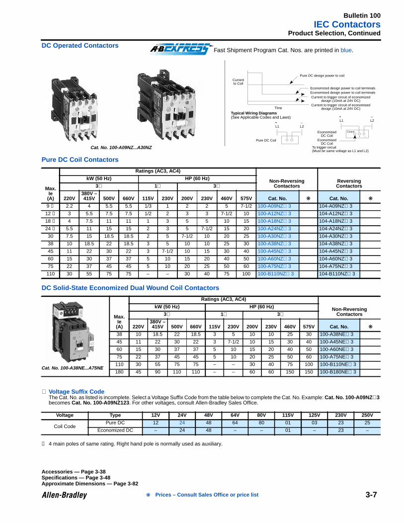
DC Operated Contactors
Pure DC Coil Contactors
DC Solid-State Economized Dual Wound Coil Contactors
⊗ Voltage Suffix CodeThe Cat. No. as listed is incomplete. Select a Voltage Suffix Code from the table below to complete the Cat. No. Example: Cat. No. 100-A09NZ ⊗3becomes Cat. No. 100-A09NZ123 . For other voltages, consult Allen-Bradley Sales Office.
➊ 4 main poles of same rating. Right hand pole is normally used as auxiliary.
Max.Ie(A)
Ratings (AC3, AC4)
Non-ReversingContactors
ReversingContactors
kW (50 Hz) HP (60 Hz)
3∅ 1∅ 3∅
220V380V –415V 500V 660V 115V 230V 200V 230V 460V 575V Cat. No. Cat. No.
9 ➊ 2.2 4 5.5 5.5 1/3 1 2 2 5 7-1/2 100-A09NZ⊗ 3 104-A09NZ⊗ 3
12 ➊ 3 5.5 7.5 7.5 1/2 2 3 3 7-1/2 10 100-A12NZ⊗ 3 104-A12NZ⊗ 3
18 ➊ 4 7.5 11 11 1 3 5 5 10 15 100-A18NZ⊗ 3 104-A18NZ⊗ 3
24 ➊ 5.5 11 15 15 2 3 5 7-1/2 15 20 100-A24NZ⊗ 3 104-A24NZ⊗ 3
30 7.5 15 18.5 18.5 2 5 7-1/2 10 20 25 100-A30NZ⊗ 3 104-A30NZ⊗ 3
38 10 18.5 22 18.5 3 5 10 10 25 30 100-A38NZ⊗ 3 104-A38NZ⊗ 3
45 11 22 30 22 3 7-1/2 10 15 30 40 100-A45NZ⊗ 3 104-A45NZ⊗ 3
60 15 30 37 37 5 10 15 20 40 50 100-A60NZ⊗ 3 104-A60NZ⊗ 3
75 22 37 45 45 5 10 20 25 50 60 100-A75NZ⊗ 3 104-A75NZ⊗ 3
110 30 55 75 75 – – 30 40 75 100 100-B110NZ⊗ 3 104-B110NZ⊗ 3
Max.Ie(A)
Ratings (AC3, AC4)
Non-ReversingContactors
kW (50 Hz) HP (60 Hz)
3∅ 1∅ 3∅
220V380V –415V 500V 660V 115V 230V 200V 230V 460V 575V Cat. No.
38 10 18.5 22 18.5 3 5 10 10 25 30 100-A38NE⊗ 3
45 11 22 30 22 3 7-1/2 10 15 30 40 100-A45NE⊗ 3
60 15 30 37 37 5 10 15 20 40 50 100-A60NE⊗ 3
75 22 37 45 45 5 10 20 25 50 60 100-A75NE⊗ 3
110 30 55 75 75 – – 30 40 75 100 100-B110NE⊗ 3
180 45 90 110 110 – – 60 60 150 150 100-B180NE⊗ 3
Voltage Type 12V 24V 48V 64V 80V 115V 125V 230V 250V
Coil CodePure DC 12 24 48 64 80 01 03 23 25
Economized DC – 24 48 – – 01 – 23 –
Fast Shipment Program Cat. Nos. are printed in blue.
Currentto Coil
Pure DC design power to coil
Economized design power to coil terminalsEconomised design power to coil terminalsCurrent to trigger circuit of economized
design (10mA at 24V DC)Current to trigger circuit of economised
design (10mA at 24V DC)Time
Typical Wiring Diagrams(See Applicable Codes and Laws)
Pure DC Coil
L1 L2
To trigger circuit(Must be same voltage as L1 and L2)
L1 L2
Control
+ –
EconomizedDC Coil
EconomisedDC Coil
88-226
+ –
+ –
Cat. No. 100-A09NZ...A30NZ
Cat. No. 100-A38NE...A75NE
Accessories — Page 3-38Specifications — Page 3-48Approximate Dimensions — Page 3-82
Prices – Consult Sales Office or price list
Bulletin 100IEC Contactors
3-8
Product Selection, Continued
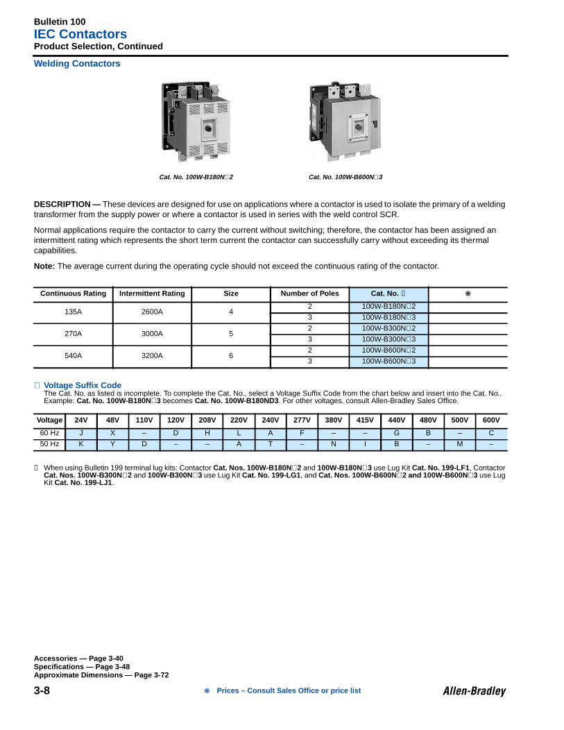
Welding Contactors
DESCRIPTION — These devices are designed for use on applications where a contactor is used to isolate the primary of a weldingtransformer from the supply power or where a contactor is used in series with the weld control SCR.
Normal applications require the contactor to carry the current without switching; therefore, the contactor has been assigned anintermittent rating which represents the short term current the contactor can successfully carry without exceeding its thermalcapabilities.
Note: The average current during the operating cycle should not exceed the continuous rating of the contactor.
⊗ Voltage Suffix CodeThe Cat. No. as listed is incomplete. To complete the Cat. No., select a Voltage Suffix Code from the chart below and insert into the Cat. No..Example: Cat. No. 100W-B180N ⊗3 becomes Cat. No. 100W-B180ND3 . For other voltages, consult Allen-Bradley Sales Office.
➊ When using Bulletin 199 terminal lug kits: Contactor Cat. Nos. 100W-B180N ⊗2 and 100W-B180N⊗3 use Lug Kit Cat. No. 199-LF1 , ContactorCat. Nos. 100W-B300N ⊗2 and 100W-B300N⊗3 use Lug Kit Cat. No. 199-LG1 , and Cat. Nos. 100W-B600N ⊗2 and 100W-B600N ⊗3 use LugKit Cat. No. 199-LJ1 .
Continuous Rating Intermittent Rating Size Number of Poles Cat. No. ➊
135A 2600A 42 100W-B180N⊗2
3 100W-B180N⊗3
270A 3000A 52 100W-B300N⊗2
3 100W-B300N⊗3
540A 3200A 62 100W-B600N⊗2
3 100W-B600N⊗3
Voltage 24V 48V 110V 120V 208V 220V 240V 277V 380V 415V 440V 480V 500V 600V
60 Hz J X – D H L A F – – G B – C
50 Hz K Y D – – A T – N I B – M –
Cat. No. 100W-B180N ⊗2 Cat. No. 100W-B600N ⊗3
Accessories — Page 3-40Specifications — Page 3-48Approximate Dimensions — Page 3-72
Prices – Consult Sales Office or price list
Bulletin 100IEC Contactors
3-9
Product Selection, Continued
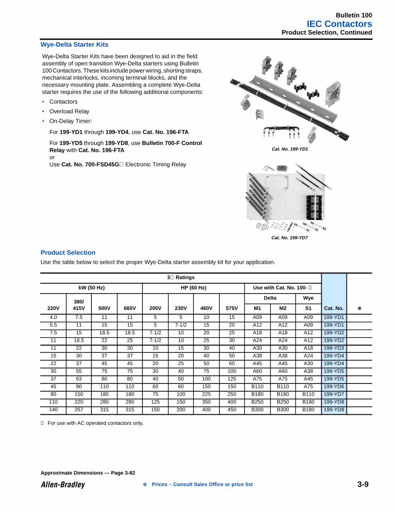
Wye-Delta Starter Kits
Product SelectionUse the table below to select the proper Wye-Delta starter assembly kit for your application.
➊ For use with AC operated contactors only.
Wye-Delta Starter Kits have been designed to aid in the fieldassembly of open transition Wye-Delta starters using Bulletin100 Contactors. These kits include power wiring, shorting straps,mechanical interlocks, incoming terminal blocks, and thenecessary mounting plate. Assembling a complete Wye-Deltastarter requires the use of the following additional components:
• Contactors
• Overload Relay
• On-Delay Timer:
For 199-YD1 through 199-YD4, use Cat. No. 196-FTA
For 199-YD5 through 199-YD8, use Bulletin 700-F ControlRelay with Cat. No. 196-FTAorUse Cat. No. 700-FSD45G⊗ Electronic Timing Relay
3∅ Ratings
Cat. No.
kW (50 Hz) HP (60 Hz) Use with Cat. No. 100- ➊
220V380/415V 500V 660V 200V 230V 460V 575V
Delta Wye
M1 M2 S1
4.0 7.5 11 11 5 5 10 15 A09 A09 A09 199-YD1
5.5 11 15 15 5 7-1/2 15 20 A12 A12 A09 199-YD1
7.5 15 18.5 18.5 7-1/2 10 20 25 A18 A18 A12 199-YD2
11 18.5 22 25 7-1/2 10 25 30 A24 A24 A12 199-YD2
11 22 30 30 10 15 30 40 A30 A30 A18 199-YD3
15 30 37 37 15 20 40 50 A38 A38 A24 199-YD4
22 37 45 45 20 25 50 60 A45 A45 A30 199-YD4
30 55 75 75 30 40 75 100 A60 A60 A38 199-YD5
37 63 80 80 40 50 100 125 A75 A75 A45 199-YD5
45 90 110 110 60 60 150 150 B110 B110 A75 199-YD6
80 150 180 180 75 100 225 250 B180 B180 B110 199-YD7
110 220 280 280 125 150 350 400 B250 B250 B180 199-YD8
140 257 315 315 150 200 400 450 B300 B300 B180 199-YD8
Cat. No. 199-YD1
Cat. No. 199-YD7
Approximate Dimensions — Page 3-82
Prices – Consult Sales Office or price list
Bulletin 100LElectrically Held Lighting Contactors
3-10
3
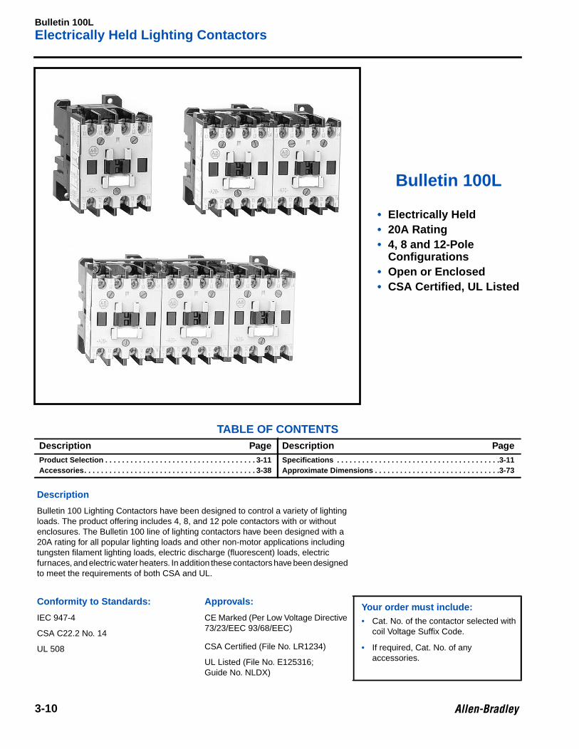
Bulletin 100L
• Electrically Held• 20A Rating• 4, 8 and 12-Pole
Configurations• Open or Enclosed• CSA Certified, UL Listed
TABLE OF CONTENTSDescription Page Description PageProduct Selection . . . . . . . . . . . . . . . . . . . . . . . . . . . . . . . . . . . . 3-11Accessories. . . . . . . . . . . . . . . . . . . . . . . . . . . . . . . . . . . . . . . . . 3-38
Specifications . . . . . . . . . . . . . . . . . . . . . . . . . . . . . . . . . . . . . . .3-11Approximate Dimensions . . . . . . . . . . . . . . . . . . . . . . . . . . . . . .3-73
Description
Bulletin 100 Lighting Contactors have been designed to control a variety of lightingloads. The product offering includes 4, 8, and 12 pole contactors with or withoutenclosures. The Bulletin 100 line of lighting contactors have been designed with a20A rating for all popular lighting loads and other non-motor applications includingtungsten filament lighting loads, electric discharge (fluorescent) loads, electricfurnaces, and electric water heaters. In addition these contactors have been designedto meet the requirements of both CSA and UL.
Conformity to Standards: App rovals:Your order must include:• Cat. No. of the contactor selected with
coil Voltage Suffix Code.
• If required, Cat. No. of anyaccessories.
IEC 947-4 CE Marked (Per Low Voltage Directive73/23/EEC 93/68/EEC)
CSA C22.2 No. 14
UL 508 CSA Certified (File No. LR1234)
UL Listed (File No. E125316;Guide No. NLDX)
Bulletin 100LElectrically Held Lighting Contactors
3-11
Product Selection
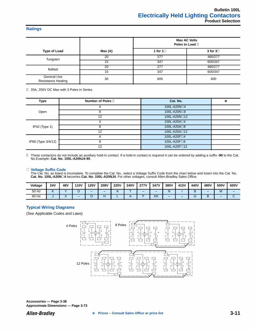
Ratings
➊ 20A, 250V DC Max with 3 Poles in Series.
➋ These contactors do not include an auxiliary hold-in contact. If a hold-in contact is required it can be ordered by adding a suffix -90 to the Cat.No.Example: Cat. No. 100L-A20NJ4-90 .
⊗ Voltage Suffix CodeThe Cat. No. as listed is incomplete. To complete the Cat. No., select a Voltage Suffix Code from the chart below and insert into the Cat. No.Cat. No. 100L-A20N ⊗4 becomes Cat. No. 100L-A20NJ4 . For other voltages, consult Allen-Bradley Sales Office.
Typical Wiring Diagrams(See Applicable Codes and Laws)
Type of Load Max (A)
Max AC VoltsPoles to Load ➊
1 for 1 ∅ 3 for 3 ∅
Tungsten20 277 480/277
15 347 600/347
Ballast20 277 480/277
15 347 600/347
General UseResistance Heating
30 600 600
Type Number of Poles ➋ Cat. No.
Open
4 100L-A20N⊗4
8 100L-A20N⊗8
12 100L-A20N⊗12
IP42 (Type 1)
4 100L-A20A⊗4
8 100L-A20A⊗8
12 100L-A20A⊗12
IP66 (Type 3/4/12)
4 100L-A20F⊗4
8 100L-A20F⊗8
12 100L-A20F⊗12
Voltage 24V 48V 110V 120V 208V 220V 240V 277V 347V 380V 415V 440V 480V 500V 600V
50 Hz K Y D – – A T – – N I B – M –
60 Hz J X – D H L A F KK – – G B – C
A1
1
T12
3
T2
4
5
T36
7
T48
A2
1
T1
2
3
T2
4
5
T36
7
T48
A2
A1
1
T1
2
3
T2
4
5
T36
7
T48
A2
1
T1
2
3
T2
4
5
T3
6
7
T4
8
1
T1
2
3
T2
4
5
T3
6
7
T4
8
1
T1
2
3
T2
4
5
T36
7
T4
8
A1
A2
A1
A2
A1
A2
12 Poles
4 Poles8 Poles
L1 L2 L4L1 L2 L3 L4 L1 L2 L3 L4
L3
L1 L2 L4L3 L1 L2 L4L3 L1 L2 L4L312 Poles
8 Poles4 Poles
Accessories — Page 3-38Approximate Dimensions — Page 3-73
Prices – Consult Sales Office or price list
Bulletin 105IEC Reversing Starters
3-12
3Enclosed Type
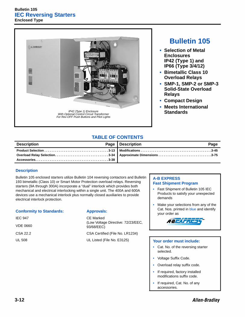
Bulletin 105• Selection of Metal
EnclosuresIP42 (Type 1) andIP66 (Type 3/4/12)
• Bimetallic Class 10Overload Relays
• SMP-1, SMP-2 or SMP-3Solid-State OverloadRelays
• Compact Design• Meets International
Standards
TABLE OF CONTENTSDescription Page Description Page
Product Selection . . . . . . . . . . . . . . . . . . . . . . . . . . . . . . . . . . . . 3-13Overload Relay Selection. . . . . . . . . . . . . . . . . . . . . . . . . . . . . . 3-34Accessories. . . . . . . . . . . . . . . . . . . . . . . . . . . . . . . . . . . . . . . . . 3-38
Modifications . . . . . . . . . . . . . . . . . . . . . . . . . . . . . . . . . . . . . . . .3-45Approximate Dimensions . . . . . . . . . . . . . . . . . . . . . . . . . . . . . .3-75
Description
Bulletin 105 enclosed starters utilize Bulletin 104 reversing contactors and Bulletin193 bimetallic (Class 10) or Smart Motor Protection overload relays. Reversingstarters (9A through 300A) incorporate a “dual” interlock which provides bothmechanical and electrical interlocking within a single unit. The 400A and 600Adevices use a mechanical interlock plus normally closed auxiliaries to provideelectrical interlock protection.
A-B EXPRESSFast Shipment Program• Fast Shipment of Bulletin 105 IEC
Products to satisfy your unexpecteddemands
• Make your selections from any of theCat. Nos. printed in blue and identifyyour order as
Conformity to Standards: App rovals:
IEC 947 CE Marked(Low Voltage Directive: 72/23/EEC,93/68/EEC)VDE 0660
CSA 22.2 CSA Certified (File No. LR1234)
UL 508 UL Listed (File No. E3125) Your order must include:• Cat. No. of the reversing starter
selected.
• Voltage Suffix Code.
• Overload relay suffix code.
• If required, factory installedmodifications suffix code.
• If required, Cat. No. of anyaccessories.
IP42 (Type 1) EnclosureWith Optional Control Circuit Transformer
For Rev-OFF Push Buttons and Pilot Lights
Bulletin 105IEC Reversing Starters
3-13
Product Selection
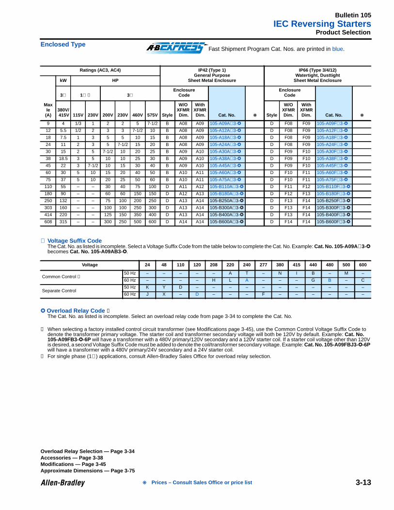
Enclosed Type
⊗ Voltage Suffix CodeThe Cat. No. as listed is incomplete. Select a Voltage Suffix Code from the table below to complete the Cat. No. Example: Cat. No. 105-A09A ⊗3-becomes Cat. No. 105-A09AB3- .
Overload Relay Code ➋The Cat. No. as listed is incomplete. Select an overload relay code from page 3-34 to complete the Cat. No.
➊ When selecting a factory installed control circuit transformer (see Modifications page 3-45), use the Common Control Voltage Suffix Code todenote the transformer primary voltage. The starter coil and transformer secondary voltage will both be 120V by default. Example: Cat. No.105-A09FB3--6P will have a transformer with a 480V primary/120V secondary and a 120V starter coil. If a starter coil voltage other than 120Vis desired, a second Voltage Suffix Code must be added to denote the coil/transformer secondary voltage. Example: Cat. No. 105-A09FBJ3- -6Pwill have a transformer with a 480V primary/24V secondary and a 24V starter coil.
➋ For single phase (1∅) applications, consult Allen-Bradley Sales Office for overload relay selection.
Ratings (AC3, AC4) IP42 (Type 1)General Purpose
Sheet Metal Enclosure
IP66 (Type 3/4/12)Watertight, Dusttight
Sheet Metal Enclosure
MaxIe(A)
kW HP
3∅ 1∅ ➋ 3∅Enclosure
Code
Cat. No.
EnclosureCode
Cat. No. 380V/ 415V 115V 230V 200V 230V 460V 575V Style
W/OXFMR Dim.
WithXFMR Dim. Style
W/OXFMRDim.
WithXFMRDim.
9 4 1/3 1 2 2 5 7-1/2 B A08 A09 105-A09A⊗3- D F08 F09 105-A09F⊗3-
12 5.5 1/2 2 3 3 7-1/2 10 B A08 A09 105-A12A⊗3- D F08 F09 105-A12F⊗3-
18 7.5 1 3 5 5 10 15 B A08 A09 105-A18A⊗3- D F08 F09 105-A18F⊗3-
24 11 2 3 5 7-1/2 15 20 B A08 A09 105-A24A⊗3- D F08 F09 105-A24F⊗3-
30 15 2 5 7-1/2 10 20 25 B A09 A10 105-A30A⊗3- D F09 F10 105-A30F⊗3-
38 18.5 3 5 10 10 25 30 B A09 A10 105-A38A⊗3- D F09 F10 105-A38F⊗3-
45 22 3 7-1/2 10 15 30 40 B A09 A10 105-A45A⊗3- D F09 F10 105-A45F⊗3-
60 30 5 10 15 20 40 50 B A10 A11 105-A60A⊗3- D F10 F11 105-A60F⊗3-
75 37 5 10 20 25 50 60 B A10 A11 105-A75A⊗3- D F10 F11 105-A75F⊗3-
110 55 – – 30 40 75 100 D A11 A12 105-B110A⊗3- D F11 F12 105-B110F⊗3-
180 90 – – 60 60 150 150 D A12 A13 105-B180A⊗3- D F12 F13 105-B180F⊗3-
250 132 – – 75 100 200 250 D A13 A14 105-B250A⊗3- D F13 F14 105-B250F⊗3-
303 160 – – 100 100 250 300 D A13 A14 105-B300A⊗3- D F13 F14 105-B300F⊗3-
414 220 – – 125 150 350 400 D A13 A14 105-B400A⊗3- D F13 F14 105-B400F⊗3-
608 315 – – 300 250 500 600 D A14 A14 105-B600A⊗3- D F14 F14 105-B600F⊗3-
Voltage 24 48 110 120 208 220 240 277 380 415 440 480 500 600
Common Control ➊50 Hz – – – – – A T – N I B – M –
60 Hz – – – – H L A – – – G B – C
Separate Control50 Hz K Y D – – – – – – – – – – –
60 Hz J X – D – – – F – – – – – –
Fast Shipment Program Cat. Nos. are printed in blue.
Overload Relay Selection — Page 3-34Accessories — Page 3-38Modifications — Page 3-45Approximate Dimensions — Page 3-75
Prices – Consult Sales Office or price list
Bulletin 105IEC Reversing Starters
3-14
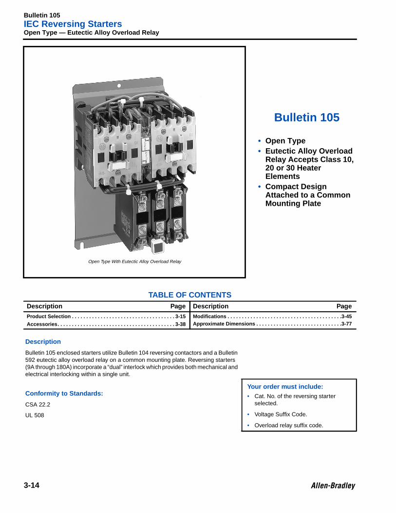
3Open Type — Eutectic Alloy Overload Relay
Bulletin 105
• Open Type• Eutectic Alloy Overload
Relay Accepts Class 10,20 or 30 HeaterElements
• Compact DesignAttached to a CommonMounting Plate
TABLE OF CONTENTSDescription Page Description Page
Product Selection . . . . . . . . . . . . . . . . . . . . . . . . . . . . . . . . . . . . 3-15
Accessories. . . . . . . . . . . . . . . . . . . . . . . . . . . . . . . . . . . . . . . . . 3-38
Modifications . . . . . . . . . . . . . . . . . . . . . . . . . . . . . . . . . . . . . . . .3-45Approximate Dimensions . . . . . . . . . . . . . . . . . . . . . . . . . . . . . .3-77
Description
Bulletin 105 enclosed starters utilize Bulletin 104 reversing contactors and a Bulletin592 eutectic alloy overload relay on a common mounting plate. Reversing starters(9A through 180A) incorporate a “dual” interlock which provides both mechanical andelectrical interlocking within a single unit.
Your order must include:• Cat. No. of the reversing starter
selected.
• Voltage Suffix Code.
• Overload relay suffix code.
Conformity to Standards:
CSA 22.2
UL 508
Open Type With Eutectic Alloy Overload Relay
Bulletin 105IEC Reversing Starters
3-15
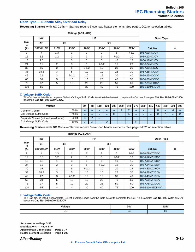
Product Selection
Open Type — Eutectic Alloy Overload RelayReversing Starters with AC Coils — Starters require 3 overload heater elements. See page 1-202 for selection tables.
⊗ Voltage Suffix CodeThe Cat. No. as listed is incomplete. Select a Voltage Suffix Code from the table below to complete the Cat. No. Example: Cat. No. 105-A09N ⊗JOVbecomes Cat. No. 105-A09NDJOV .
Reversing Starters with DC Coils — Starters require 3 overload heater elements. See page 1-202 for selection tables.
⊗ Voltage Suffix CodeThe Cat. No. as listed is incomplete. Select a voltage code from the table below to complete the Cat. No. Example: Cat. No. 105-A09NZ ⊗JOVbecomes Cat. No. 105-A09NZ24JOV .
Ratings (AC3, AC4)
Open TypeMaxIe(A)
kW HP
3∅ 1∅ 3∅
Cat. No. 380V/415V 115V 230V 200V 230V 460V 575V
9 4 1/3 1 2 2 5 7-1/2 105-A09N⊗JOV
12 5.5 1/2 2 3 3 7-1/2 10 105-A12N⊗JOV
18 7.5 1 3 5 5 10 15 105-A18N⊗JOV
24 11 2 3 5 7-1/2 15 20 105-A24N⊗JOV
30 15 2 5 7-1/2 10 20 25 105-A30N⊗KOV
38 18.5 3 5 10 10 25 30 105-A38N⊗COV
45 22 3 7-1/2 10 15 30 40 105-A45N⊗COV
60 30 5 10 15 20 40 50 105-A60N⊗COV
75 37 5 10 20 25 50 60 105-A75N⊗DOV
110 55 – – 30 40 75 100 105-B110N⊗DOV
Voltage 24 48 110 120 208 220 240 277 380 415 440 480 500 600
Common ControlCoil Voltage Suffix Code
50 Hz – – – – – A T – N I B – M –
60 Hz – – – – H L A – – – G B – C
Separate Control (without transformer)Coil Voltage Suffix Code
50 Hz K Y D – – – – – – – – – – –
60 Hz J X – D – – – F – – – – – –
Ratings (AC3, AC4)
Open TypeMaxIe(A)
kW HP
3∅ 1∅ 3∅
Cat. No. 380V/415V 115V 230V 200V 230V 460V 575V
9 4 1/3 1 2 2 5 7-1/2 105-A09NZ⊗JOV
12 5.5 1/2 2 3 3 7-1/2 10 105-A12NZ⊗JOV
18 7.5 1 3 5 5 10 15 105-A18NZ⊗JOV
24 11 2 3 5 7-1/2 15 20 105-A24NZ⊗JOV
30 15 2 5 7-1/2 10 20 25 105-A30NZ⊗KOV
38 18.5 3 5 10 10 25 30 105-A38NZ⊗COV
45 22 3 7-1/2 10 15 30 40 105-A45NZ⊗COV
60 30 5 10 15 20 40 50 105-A60NZ⊗COV
75 37 5 10 20 25 50 60 105-A75NZ⊗DOV
110 55 – – 30 40 75 100 105-B110NZ⊗DOV
Voltage 24V 115V
DC 24 01
Accessories — Page 3-38Modifications — Page 3-45Approximate Dimensions — Page 3-77Heater Element Selection — Page 1-202
Prices – Consult Sales Office or price list
Bulletin 106IEC Reversing Combination Starters
3-16
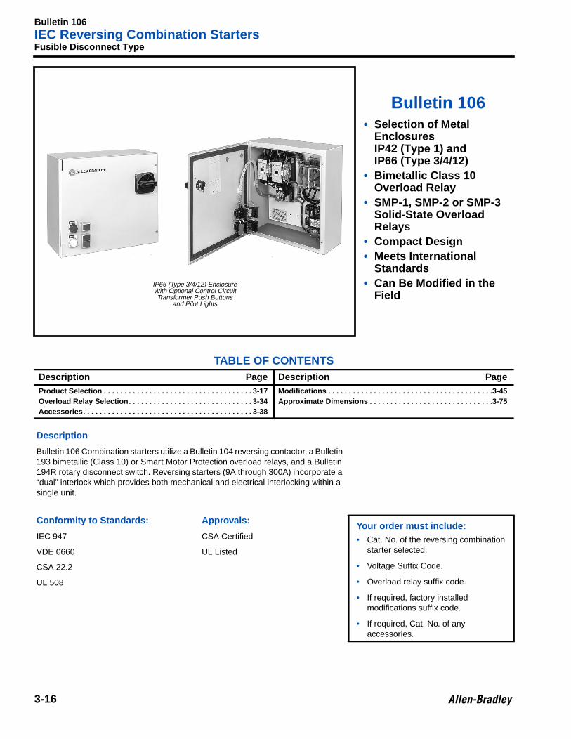
3Fusible Disconnect Type
Bulletin 106• Selection of Metal
EnclosuresIP42 (Type 1) andIP66 (Type 3/4/12)
• Bimetallic Class 10Overload Relay
• SMP-1, SMP-2 or SMP-3Solid-State OverloadRelays
• Compact Design• Meets International
Standards• Can Be Modified in the
Field
TABLE OF CONTENTSDescription Page Description PageProduct Selection . . . . . . . . . . . . . . . . . . . . . . . . . . . . . . . . . . . . 3-17Overload Relay Selection. . . . . . . . . . . . . . . . . . . . . . . . . . . . . . 3-34Accessories. . . . . . . . . . . . . . . . . . . . . . . . . . . . . . . . . . . . . . . . . 3-38
Modifications . . . . . . . . . . . . . . . . . . . . . . . . . . . . . . . . . . . . . . . .3-45Approximate Dimensions . . . . . . . . . . . . . . . . . . . . . . . . . . . . . .3-75
Description
Bulletin 106 Combination starters utilize a Bulletin 104 reversing contactor, a Bulletin193 bimetallic (Class 10) or Smart Motor Protection overload relays, and a Bulletin194R rotary disconnect switch. Reversing starters (9A through 300A) incorporate a“dual” interlock which provides both mechanical and electrical interlocking within asingle unit.
Conformity to Standards: App rovals:Your order must include:• Cat. No. of the reversing combination
starter selected.
• Voltage Suffix Code.
• Overload relay suffix code.
• If required, factory installedmodifications suffix code.
• If required, Cat. No. of anyaccessories.
IEC 947 CSA Certified
VDE 0660 UL Listed
CSA 22.2
UL 508
IP66 (Type 3/4/12) EnclosureWith Optional Control CircuitTransformer Push Buttons
and Pilot Lights
Bulletin 106IEC Reversing Combination Starters
3-17
Product Selection
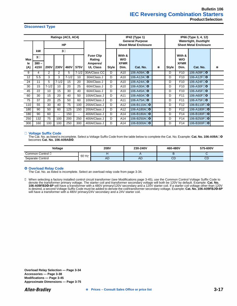
Disconnect Type
⊗ Voltage Suffix CodeThe Cat. No. as listed is incomplete. Select a Voltage Suffix Code from the table below to complete the Cat. No. Example: Cat. No. 106-A09A ⊗becomes Cat. No. 106-A09AB .
Overload Relay CodeThe Cat. No. as listed is incomplete. Select an overload relay code from page 3-34.
➊ When selecting a factory installed control circuit transformer (see Modifications page 3-45), use the Common Control Voltage Suffix Code todenote the transformer primary voltage. The starter coil and transformer secondary voltage will both be 120V by default. Example: Cat. No.106-A09FB3-6P will have a transformer with a 480V primary/120V secondary and a 120V starter coil. If a starter coil voltage other than 120Vis desired, a second Voltage Suffix Code must be added to denote the coil/transformer secondary voltage. Example: Cat. No. 106-A09FBJ -6Pwill have a transformer with a 480V primary/24V secondary and a 24V starter coil.
Ratings (AC3, AC4) IP42 (Type 1)General Purpose
Sheet Metal Enclosure
IP66 (Type 3, 4, 12)Watertight, Dusttight
Sheet Metal Enclosure
MaxIe(A)
kW
HP
Fuse ClipRating
Amperes/UL Class
3∅
Style
With &W/O
XFMRDim. Cat. No. Style
With &W/O
XFMRDim. Cat. No.
3∅
200V 230V 460V 575V380 –415V
9 4 2 2 5 7-1/2 30A/Class CC D A10 106-A09A⊗ D F10 106-A09F⊗
12 5.5 3 3 7-1/2 10 30A/Class J D A10 106-A12A⊗ D F10 106-A12F⊗
24 11 5 7-1/2 15 20 30A/Class J D A10 106-A24A⊗ D F10 106-A24F⊗
30 15 7-1/2 10 20 25 60A/Class J D A10 106-A30A⊗ D F10 106-A30F⊗
45 22 10 15 30 40 60A/Class J D A10 106-A45A⊗ D F10 106-A45F⊗
60 30 15 20 40 50 100A/Class J D A11 106-A60A⊗ D F11 106-A60F⊗
75 37 20 25 50 60 100A/Class J D A11 106-A75A⊗ D F11 106-A75F⊗
110 55 30 40 75 100 200A/Class J D A12 106-B110A⊗ D F12 106-B110F⊗
180 90 50 60 125 150 200A/Class J D A12 106-A180A⊗ D F12 106-A180F⊗
180 90 60 – 150 – 400A/Class J D A14 106-B180A⊗ D F14 106-B180F⊗
250 132 75 100 200 250 400A/Class J D A14 106-B250A⊗ D F14 106-B250F⊗
300 160 100 100 250 300 400A/Class J D A14 106-B300A⊗ D F14 106-B300F⊗
Voltage 208V 230-240V 460-480V 575-600V
Common Control ➊60 Hz
H A B C
Separate Control AD AD CD CD
Overload Relay Selection — Page 3-34Accessories — Page 3-38Modifications — Page 3-45Approximate Dimensions — Page 3-75
Prices – Consult Sales Office or price list
Bulletin 109IEC Non-Reversing Starters
3-18
3aEnclosed Type — Molded Plastic
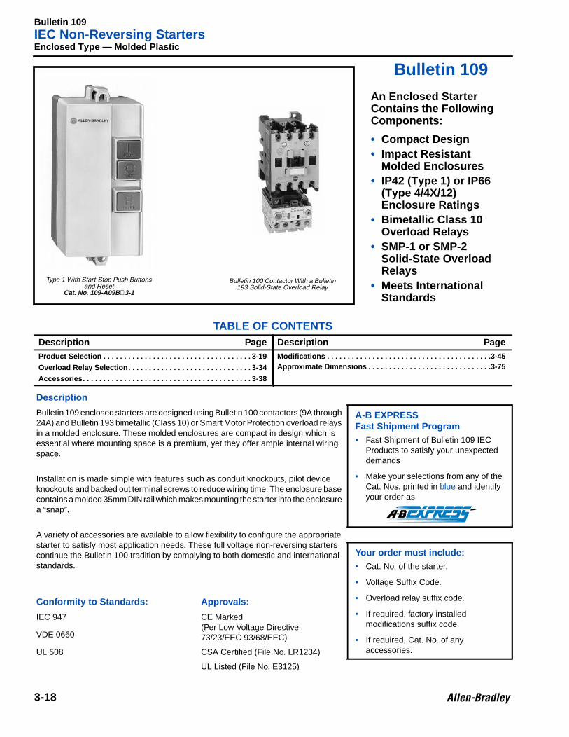
Bulletin 109
An Enclosed StarterContains the FollowingComponents:
• Compact Design• Impact Resistant
Molded Enclosures• IP42 (Type 1) or IP66
(Type 4/4X/12)Enclosure Ratings
• Bimetallic Class 10Overload Relays
• SMP-1 or SMP-2Solid-State OverloadRelays
• Meets InternationalStandards
TABLE OF CONTENTSDescription Page Description PageProduct Selection . . . . . . . . . . . . . . . . . . . . . . . . . . . . . . . . . . . . 3-19
Overload Relay Selection. . . . . . . . . . . . . . . . . . . . . . . . . . . . . . 3-34
Accessories. . . . . . . . . . . . . . . . . . . . . . . . . . . . . . . . . . . . . . . . . 3-38
Modifications . . . . . . . . . . . . . . . . . . . . . . . . . . . . . . . . . . . . . . . .3-45Approximate Dimensions . . . . . . . . . . . . . . . . . . . . . . . . . . . . . .3-75
Description
Bulletin 109 enclosed starters are designed using Bulletin 100 contactors (9A through24A) and Bulletin 193 bimetallic (Class 10) or Smart Motor Protection overload relaysin a molded enclosure. These molded enclosures are compact in design which isessential where mounting space is a premium, yet they offer ample internal wiringspace.
A-B EXPRESSFast Shipment Program• Fast Shipment of Bulletin 109 IEC
Products to satisfy your unexpecteddemands
• Make your selections from any of theCat. Nos. printed in blue and identifyyour order as
Installation is made simple with features such as conduit knockouts, pilot deviceknockouts and backed out terminal screws to reduce wiring time. The enclosure basecontains a molded 35mm DIN rail which makes mounting the starter into the enclosurea “snap”.
A variety of accessories are available to allow flexibility to configure the appropriatestarter to satisfy most application needs. These full voltage non-reversing starterscontinue the Bulletin 100 tradition by complying to both domestic and internationalstandards.
Your order must include:• Cat. No. of the starter.
• Voltage Suffix Code.
• Overload relay suffix code.
• If required, factory installedmodifications suffix code.
• If required, Cat. No. of anyaccessories.
Conformity to Standards: App rovals:
IEC 947 CE Marked(Per Low Voltage Directive73/23/EEC 93/68/EEC)VDE 0660
UL 508 CSA Certified (File No. LR1234)
UL Listed (File No. E3125)
Type 1 With Start-Stop Push Buttonsand Reset
Cat. No. 109-A09B ⊗3-1
Bulletin 100 Contactor With a Bulletin193 Solid-State Overload Relay.
Bulletin 109IEC Non-Reversing Starters
3-19
Product Selection
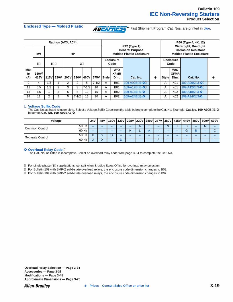
Enclosed Type — Molded Plastic
⊗ Voltage Suffix CodeThe Cat. No. as listed is incomplete. Select a Voltage Suffix Code from the table below to complete the Cat. No. Example: Cat. No. 109-A09B ⊗3-becomes Cat. No. 109-A09BA3- .
Overload Relay Code ➊The Cat. No. as listed is incomplete. Select an overload relay code from page 3-34 to complete the Cat. No.
➊ For single phase (1∅) applications, consult Allen-Bradley Sales Office for overload relay selection.➋ For Bulletin 109 with SMP-2 solid-state overload relays, the enclosure code dimension changes to B02.➌ For Bulletin 109 with SMP-2 solid-state overload relays, the enclosure code dimension changes to K02.
Ratings (AC3, AC4)IP42 (Type 1)
General PurposeMolded Plastic Enclosure
IP66 (Type 4, 4X, 12)Watertight, DusttightCorrosion Resistant
Molded Plastic Enclosure
MaxIe(A)
kW HP
3∅ 1∅➊ 3∅Enclosure
Code
Cat. No.
EnclosureCode
Cat. No.
380V/415V 115V 230V 200V 230V 460V 575V Style
W/OXFMRDim. Style
W/OXFMRDim.
9 4 1/3 1 2 2 5 7-1/2 A B01 109-A09B⊗3-➋ A K01 109-A09K⊗3-➌
12 5.5 1/2 2 3 3 7-1/2 10 A B01 109-A12B⊗3-➋ A K01 109-A12K⊗3-➌
18 7.5 1 3 5 5 10 15 A B02 109-A18B⊗3- A K02 109-A18K⊗3-
24 11 2 3 5 7-1/2 15 20 A B02 109-A24B⊗3- A K02 109-A24K⊗3-
Voltage 24V 48V 110V 120V 208V 220V 240V 277V 380V 415V 440V 480V 500V 600V
Common Control50 Hz – – – – – A T – N I B – M –
60 Hz – – – – H L A – – – G B – C
Separate Control50 Hz K Y D – – – – – – – – – – –
60 Hz J X – D – – – F – – – – – –
Fast Shipment Program Cat. Nos. are printed in blue.
Overload Relay Selection — Page 3-34Accessories — Page 3-38Modifications — Page 3-45Approximate Dimensions — Page 3-75
Prices – Consult Sales Office or price list
Bulletin 109IEC Non-Reversing Starters
3-20
3Enclosed Type — Sheet Metal
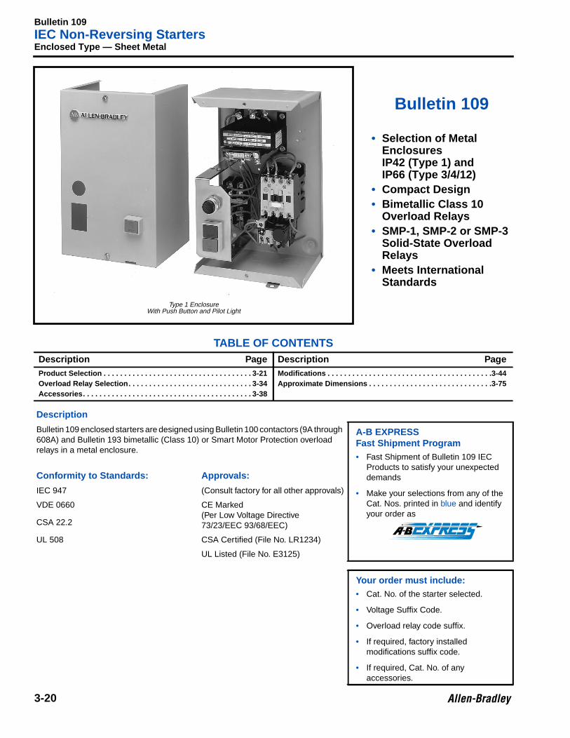
Bulletin 109
• Selection of MetalEnclosuresIP42 (Type 1) andIP66 (Type 3/4/12)
• Compact Design• Bimetallic Class 10
Overload Relays• SMP-1, SMP-2 or SMP-3
Solid-State OverloadRelays
• Meets InternationalStandards
TABLE OF CONTENTSDescription Page Description PageProduct Selection . . . . . . . . . . . . . . . . . . . . . . . . . . . . . . . . . . . . 3-21Overload Relay Selection. . . . . . . . . . . . . . . . . . . . . . . . . . . . . . 3-34Accessories. . . . . . . . . . . . . . . . . . . . . . . . . . . . . . . . . . . . . . . . . 3-38
Modifications . . . . . . . . . . . . . . . . . . . . . . . . . . . . . . . . . . . . . . . .3-44Approximate Dimensions . . . . . . . . . . . . . . . . . . . . . . . . . . . . . .3-75
Description
Bulletin 109 enclosed starters are designed using Bulletin 100 contactors (9A through608A) and Bulletin 193 bimetallic (Class 10) or Smart Motor Protection overloadrelays in a metal enclosure.
A-B EXPRESSFast Shipment Program• Fast Shipment of Bulletin 109 IEC
Products to satisfy your unexpecteddemands
• Make your selections from any of theCat. Nos. printed in blue and identifyyour order as
Conformity to Standards: App rovals:
IEC 947 (Consult factory for all other approvals)
VDE 0660 CE Marked(Per Low Voltage Directive73/23/EEC 93/68/EEC)CSA 22.2
UL 508 CSA Certified (File No. LR1234)
UL Listed (File No. E3125)
Your order must include:• Cat. No. of the starter selected.
• Voltage Suffix Code.
• Overload relay code suffix.
• If required, factory installedmodifications suffix code.
• If required, Cat. No. of anyaccessories.
Type 1 EnclosureWith Push Button and Pilot Light
Bulletin 109IEC Non-Reversing Starters
3-21
Product Selection
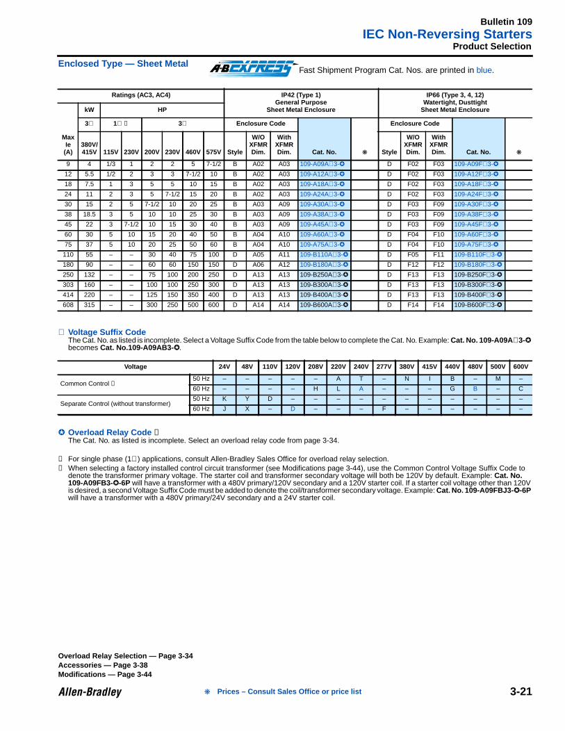
Enclosed Type — Sheet Metal
⊗ Voltage Suffix CodeThe Cat. No. as listed is incomplete. Select a Voltage Suffix Code from the table below to complete the Cat. No. Example: Cat. No. 109-A09A ⊗3-becomes Cat. No.109-A09AB3- .
Overload Relay Code ➊The Cat. No. as listed is incomplete. Select an overload relay code from page 3-34.
➊ For single phase (1∅) applications, consult Allen-Bradley Sales Office for overload relay selection.➋ When selecting a factory installed control circuit transformer (see Modifications page 3-44), use the Common Control Voltage Suffix Code to
denote the transformer primary voltage. The starter coil and transformer secondary voltage will both be 120V by default. Example: Cat. No.109-A09FB3--6P will have a transformer with a 480V primary/120V secondary and a 120V starter coil. If a starter coil voltage other than 120Vis desired, a second Voltage Suffix Code must be added to denote the coil/transformer secondary voltage. Example: Cat. No. 109-A09FBJ3- -6Pwill have a transformer with a 480V primary/24V secondary and a 24V starter coil.
Ratings (AC3, AC4) IP42 (Type 1)General Purpose
Sheet Metal Enclosure
IP66 (Type 3, 4, 12)Watertight, Dusttight
Sheet Metal Enclosure
MaxIe(A)
kW HP
3∅ 1∅ ➊ 3∅ Enclosure Code
Cat. No.
Enclosure Code
Cat. No. 380V/415V 115V 230V 200V 230V 460V 575V Style
W/OXFMRDim.
WithXFMRDim. Style
W/OXFMRDim.
WithXFMRDim.
9 4 1/3 1 2 2 5 7-1/2 B A02 A03 109-A09A⊗3- D F02 F03 109-A09F⊗3-
12 5.5 1/2 2 3 3 7-1/2 10 B A02 A03 109-A12A⊗3- D F02 F03 109-A12F⊗3-
18 7.5 1 3 5 5 10 15 B A02 A03 109-A18A⊗3- D F02 F03 109-A18F⊗3-
24 11 2 3 5 7-1/2 15 20 B A02 A03 109-A24A⊗3- D F02 F03 109-A24F⊗3-
30 15 2 5 7-1/2 10 20 25 B A03 A09 109-A30A⊗3- D F03 F09 109-A30F⊗3-
38 18.5 3 5 10 10 25 30 B A03 A09 109-A38A⊗3- D F03 F09 109-A38F⊗3-
45 22 3 7-1/2 10 15 30 40 B A03 A09 109-A45A⊗3- D F03 F09 109-A45F⊗3-
60 30 5 10 15 20 40 50 B A04 A10 109-A60A⊗3- D F04 F10 109-A60F⊗3-
75 37 5 10 20 25 50 60 B A04 A10 109-A75A⊗3- D F04 F10 109-A75F⊗3-
110 55 – – 30 40 75 100 D A05 A11 109-B110A⊗3- D F05 F11 109-B110F⊗3-
180 90 – – 60 60 150 150 D A06 A12 109-B180A⊗3- D F12 F12 109-B180F⊗3-
250 132 – – 75 100 200 250 D A13 A13 109-B250A⊗3- D F13 F13 109-B250F⊗3-
303 160 – – 100 100 250 300 D A13 A13 109-B300A⊗3- D F13 F13 109-B300F⊗3-
414 220 – – 125 150 350 400 D A13 A13 109-B400A⊗3- D F13 F13 109-B400F⊗3-
608 315 – – 300 250 500 600 D A14 A14 109-B600A⊗3- D F14 F14 109-B600F⊗3-
Voltage 24V 48V 110V 120V 208V 220V 240V 277V 380V 415V 440V 480V 500V 600V
Common Control ➋50 Hz – – – – – A T – N I B – M –
60 Hz – – – – H L A – – – G B – C
Separate Control (without transformer)50 Hz K Y D – – – – – – – – – – –
60 Hz J X – D – – – F – – – – – –
Fast Shipment Program Cat. Nos. are printed in blue.
Overload Relay Selection — Page 3-34Accessories — Page 3-38Modifications — Page 3-44
Prices – Consult Sales Office or price list
Bulletin 109IEC Non-Reversing Starters
3-22
3Open Type — Eutectic Alloy Overload Relay
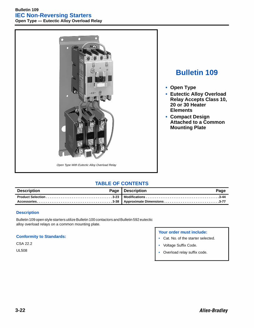
Bulletin 109
• Open Type• Eutectic Alloy Overload
Relay Accepts Class 10,20 or 30 HeaterElements
• Compact DesignAttached to a CommonMounting Plate
TABLE OF CONTENTSDescription Page Description PageProduct Selection . . . . . . . . . . . . . . . . . . . . . . . . . . . . . . . . . . . . 3-23Accessories. . . . . . . . . . . . . . . . . . . . . . . . . . . . . . . . . . . . . . . . . 3-38
Modifications . . . . . . . . . . . . . . . . . . . . . . . . . . . . . . . . . . . . . . . .3-44Approximate Dimensions . . . . . . . . . . . . . . . . . . . . . . . . . . . . . .3-77
Description
Bulletin 109 open style starters utilize Bulletin 100 contactors and Bulletin 592 eutecticalloy overload relays on a common mounting plate.
Your order must include:• Cat. No. of the starter selected.
• Voltage Suffix Code.
• Overload relay suffix code.
Conformity to Standards:
CSA 22.2
UL508
Open Type With Eutectic Alloy Overload Relay
Bulletin 109IEC Non-Reversing Starters
3-23
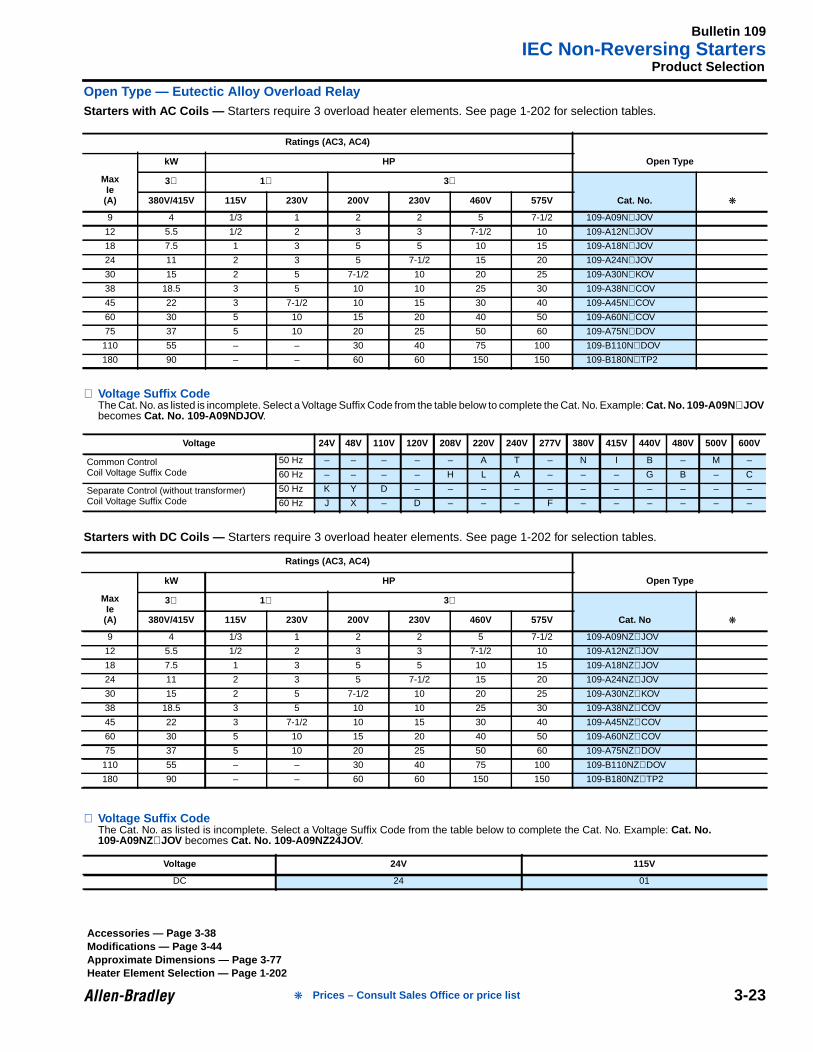
Product Selection
Open Type — Eutectic Alloy Overload RelayStarters with AC Coils — Starters require 3 overload heater elements. See page 1-202 for selection tables.
⊗ Voltage Suffix CodeThe Cat. No. as listed is incomplete. Select a Voltage Suffix Code from the table below to complete the Cat. No. Example: Cat. No. 109-A09N ⊗JOVbecomes Cat. No. 109-A09NDJOV .
Starters with DC Coils — Starters require 3 overload heater elements. See page 1-202 for selection tables.
⊗ Voltage Suffix CodeThe Cat. No. as listed is incomplete. Select a Voltage Suffix Code from the table below to complete the Cat. No. Example: Cat. No.109-A09NZ⊗JOV becomes Cat. No. 109-A09NZ24JOV .
Ratings (AC3, AC4)
Open Type
MaxIe(A)
kW HP
3∅ 1∅ 3∅
Cat. No. 380V/415V 115V 230V 200V 230V 460V 575V
9 4 1/3 1 2 2 5 7-1/2 109-A09N⊗JOV
12 5.5 1/2 2 3 3 7-1/2 10 109-A12N⊗JOV
18 7.5 1 3 5 5 10 15 109-A18N⊗JOV
24 11 2 3 5 7-1/2 15 20 109-A24N⊗JOV
30 15 2 5 7-1/2 10 20 25 109-A30N⊗KOV
38 18.5 3 5 10 10 25 30 109-A38N⊗COV
45 22 3 7-1/2 10 15 30 40 109-A45N⊗COV
60 30 5 10 15 20 40 50 109-A60N⊗COV
75 37 5 10 20 25 50 60 109-A75N⊗DOV
110 55 – – 30 40 75 100 109-B110N⊗DOV
180 90 – – 60 60 150 150 109-B180N⊗TP2
Voltage 24V 48V 110V 120V 208V 220V 240V 277V 380V 415V 440V 480V 500V 600V
Common ControlCoil Voltage Suffix Code
50 Hz – – – – – A T – N I B – M –
60 Hz – – – – H L A – – – G B – C
Separate Control (without transformer)Coil Voltage Suffix Code
50 Hz K Y D – – – – – – – – – – –
60 Hz J X – D – – – F – – – – – –
Ratings (AC3, AC4)
Open Type
MaxIe(A)
kW HP
3∅ 1∅ 3∅
Cat. No 380V/415V 115V 230V 200V 230V 460V 575V
9 4 1/3 1 2 2 5 7-1/2 109-A09NZ⊗JOV
12 5.5 1/2 2 3 3 7-1/2 10 109-A12NZ⊗JOV
18 7.5 1 3 5 5 10 15 109-A18NZ⊗JOV
24 11 2 3 5 7-1/2 15 20 109-A24NZ⊗JOV
30 15 2 5 7-1/2 10 20 25 109-A30NZ⊗KOV
38 18.5 3 5 10 10 25 30 109-A38NZ⊗COV
45 22 3 7-1/2 10 15 30 40 109-A45NZ⊗COV
60 30 5 10 15 20 40 50 109-A60NZ⊗COV
75 37 5 10 20 25 50 60 109-A75NZ⊗DOV
110 55 – – 30 40 75 100 109-B110NZ⊗DOV
180 90 – – 60 60 150 150 109-B180NZ⊗TP2
Voltage 24V 115V
DC 24 01
Accessories — Page 3-38Modifications — Page 3-44Approximate Dimensions — Page 3-77Heater Element Selection — Page 1-202
Prices – Consult Sales Office or price list
Bulletin 112IEC Combination Starters
3-24
3Fusible Disconnect Type
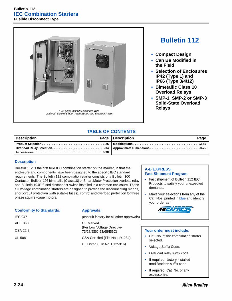
Bulletin 112
• Compact Design• Can Be Modified in
the Field• Selection of Enclosures
IP42 (Type 1) andIP66 (Type 3/4/12)
• Bimetallic Class 10Overload Relays
• SMP-1, SMP-2 or SMP-3Solid-State OverloadRelays
TABLE OF CONTENTSDescription Page Description PageProduct Selection . . . . . . . . . . . . . . . . . . . . . . . . . . . . . . . . . . . . 3-25Overload Relay Selection. . . . . . . . . . . . . . . . . . . . . . . . . . . . . . 3-34Accessories. . . . . . . . . . . . . . . . . . . . . . . . . . . . . . . . . . . . . . . . . 3-38
Modifications . . . . . . . . . . . . . . . . . . . . . . . . . . . . . . . . . . . . . . . .3-46Approximate Dimensions . . . . . . . . . . . . . . . . . . . . . . . . . . . . . .3-75
Description
Bulletin 112 is the first true IEC combination starter on the market, in that theenclosure and components have been designed to the specific IEC standardrequirements. The Bulletin 112 combination starter consists of a Bulletin 100Contactor, Bulletin 193 bimetallic (Class 10) or Smart Motor Protection overload relayand Bulletin 194R fused disconnect switch installed in a common enclosure. Thesefull voltage combination starters are designed to provide the disconnecting means,short circuit protection (with suitable fuses), control and overload protection for threephase squirrel-cage motors.
A-B EXPRESSFast Shipment Program• Fast shipment of Bulletin 112 IEC
Products to satisfy your unexpecteddemands.
• Make your selections from any of theCat. Nos. printed in blue and identifyyour order as
Conformity to Standards: App rovals:
IEC 947 (consult factory for all other approvals)
VDE 0660 CE Marked(Per Low Voltage Directive73/23/EEC 93/68/EEC)CSA 22.2 Your order must include:
• Cat. No. of the combination starterselected.
• Voltage Suffix Code.
• Overload relay suffix code.
• If required, factory installedmodifications suffix code.
• If required, Cat. No. of anyaccessories.
UL 508 CSA Certified (File No. LR1234)
UL Listed (File No. E125316)
IP66 (Type 3/4/12) Enclosure WithOptional “START-STOP” Push Button and External Reset

Bulletin 112IEC Combination Starters
3-25
Product Selection
Fusible Disconnect Type
⊗ Voltage Suffix CodeThe Cat. No. as listed is incomplete. Select a Voltage Suffix Code from the table below to complete the Cat. No. Example: Cat. No. 112-A09A ⊗becomes Cat. No. 112-A09AB .
Overload Relay CodeThe Cat. No. as listed is incomplete. Select an overload relay code from page 3-34 to complete the Cat. No.
➊ When selecting a factory installed control circuit transformer (see Modifications page 3-44), use the Common Control Voltage Suffix Code todenote the transformer primary voltage. The starter coil and transformer secondary voltage will both be 120V by default. Example: Cat. No.112-A09FB3--6P will have a transformer with a 480V primary/120V secondary and a 120V starter coil. If a starter coil voltage other than 120Vis desired, a second Voltage Suffix Code must be added to denote the coil/transformer secondary voltage. Example: Cat. No. 112-A09FBJ3- -6Pwill have a transformer with a 480V primary/24V secondary and a 24V starter coil.
Ratings (AC3, AC4) IP42 (Type 1)General Purpose
Sheet Metal Enclosure
IP66 (Type 3/4/12)Watertight, Dusttight
Sheet Metal Enclosure
MaxIe(A)
HP
Fuse ClipRating
Amperes/UL Class
3 ∅
Style
With &W/O
XFMRDim. Cat. No. Style
With &W/O
XFMRDim. Cat. No. 200V 230V 460V 575V
9 2 2 5 7-1/2 30A/Class CC D A04 112-A09A⊗ D F04 112-A09F⊗
12 3 3 7-1/2 10 30A/Class J D A04 112-A12A⊗ D F04 112-A12F⊗
24 5 7-1/2 15 20 30A/Class J D A04 112-A24A⊗ D F04 112-A24F⊗
30 7-1/2 10 20 25 60A/Class J D A10 112-A30A⊗ D F10 112-A30F⊗
45 10 15 30 40 60A/Class J D A10 112-A45A⊗ D F10 112-A45F⊗
60 15 20 40 50 100A/Class J D A11 112-A60A⊗ D F11 112-A60F⊗
75 20 25 50 60 100A/Class J D A11 112-A75A⊗ D F11 112-A75F⊗
110 30 40 75 100 200A/Class J D A12 112-B110A⊗ D F12 112-B110F⊗
180 50 60 125 150 200A/Class J D A12 112-A180A⊗ D F12 112-A180F⊗
180 60 – 150 – 400A/Class J D A13 112-B180A⊗ D F13 112-B180F⊗
250 75 100 200 250 400A/Class J D A13 112-B250A⊗ D F13 112-B250F⊗
300 100 100 250 300 400A/Class J D A13 112-B300A⊗ D F13 112-B300F⊗
Voltage 208V 230-240V 460-480V 575-600V
Common Control ➊60 Hz
H A B C
Separate Control AD AD CD CD
Fast Shipment Program Cat. Nos. are printed in blue.
Overload Relay Selection — Page 3-34Accessories — Page 3-38Modifications — Page 3-44Approximate Dimensions — Page 3-75
Prices – Consult Sales Office or price list
Bulletin 113IEC Combination Starters
3-26
3Circuit Breaker Type
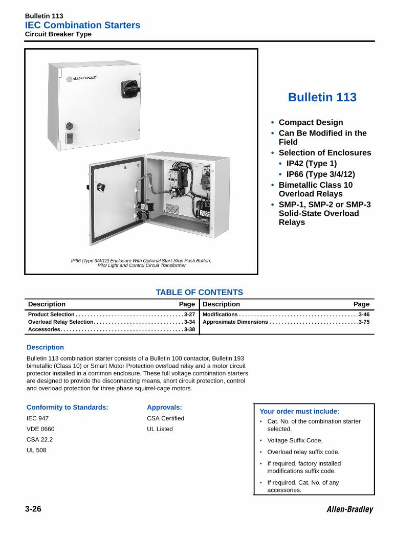
Bulletin 113
• Compact Design• Can Be Modified in the
Field• Selection of Enclosures
• IP42 (Type 1)• IP66 (Type 3/4/12)
• Bimetallic Class 10Overload Relays
• SMP-1, SMP-2 or SMP-3Solid-State OverloadRelays
TABLE OF CONTENTSDescription Page Description PageProduct Selection . . . . . . . . . . . . . . . . . . . . . . . . . . . . . . . . . . . . 3-27Overload Relay Selection. . . . . . . . . . . . . . . . . . . . . . . . . . . . . . 3-34Accessories. . . . . . . . . . . . . . . . . . . . . . . . . . . . . . . . . . . . . . . . . 3-38
Modifications . . . . . . . . . . . . . . . . . . . . . . . . . . . . . . . . . . . . . . . .3-46Approximate Dimensions . . . . . . . . . . . . . . . . . . . . . . . . . . . . . .3-75
Description
Bulletin 113 combination starter consists of a Bulletin 100 contactor, Bulletin 193bimetallic (Class 10) or Smart Motor Protection overload relay and a motor circuitprotector installed in a common enclosure. These full voltage combination startersare designed to provide the disconnecting means, short circuit protection, controland overload protection for three phase squirrel-cage motors.
Conformity to Standards: App rovals:Your order must include:• Cat. No. of the combination starter
selected.
• Voltage Suffix Code.
• Overload relay suffix code.
• If required, factory installedmodifications suffix code.
• If required, Cat. No. of anyaccessories.
IEC 947 CSA Certified
VDE 0660 UL Listed
CSA 22.2
UL 508
IP66 (Type 3/4/12) Enclosure With Optional Start-Stop Push Button,Pilot Light and Control Circuit Transformer
Bulletin 113IEC Combination Starters
3-27
Product Selection
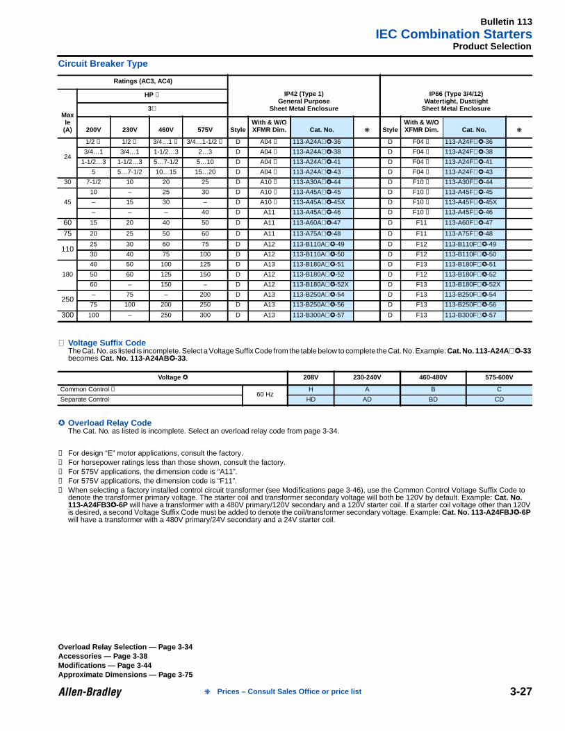
Circuit Breaker Type
⊗ Voltage Suffix CodeThe Cat. No. as listed is incomplete. Select a Voltage Suffix Code from the table below to complete the Cat. No. Example: Cat. No. 113-A24A ⊗-33becomes Cat. No. 113-A24AB -33.
Overload Relay CodeThe Cat. No. as listed is incomplete. Select an overload relay code from page 3-34.
➊ For design “E” motor applications, consult the factory.➋ For horsepower ratings less than those shown, consult the factory.➌ For 575V applications, the dimension code is “A11”.➍ For 575V applications, the dimension code is “F11”.➎ When selecting a factory installed control circuit transformer (see Modifications page 3-46), use the Common Control Voltage Suffix Code to
denote the transformer primary voltage. The starter coil and transformer secondary voltage will both be 120V by default. Example: Cat. No.113-A24FB3-6P will have a transformer with a 480V primary/120V secondary and a 120V starter coil. If a starter coil voltage other than 120Vis desired, a second Voltage Suffix Code must be added to denote the coil/transformer secondary voltage. Example: Cat. No. 113-A24FBJ -6Pwill have a transformer with a 480V primary/24V secondary and a 24V starter coil.
Ratings (AC3, AC4)
IP42 (Type 1)General Purpose
Sheet Metal Enclosure
IP66 (Type 3/4/12)Watertight, Dusttight
Sheet Metal EnclosureMaxIe(A)
HP ➊
3∅
200V 230V 460V 575V StyleWith & W/OXFMR Dim. Cat. No. Style
With & W/OXFMR Dim. Cat. No.
24
1/2 ➋ 1/2 ➋ 3/4…1 ➋ 3/4…1-1/2 ➋ D A04 ➌ 113-A24A⊗-36 D F04 ➍ 113-A24F⊗-36
3/4…1 3/4…1 1-1/2…3 2…3 D A04 ➌ 113-A24A⊗-38 D F04 ➍ 113-A24F⊗-38
1-1/2…3 1-1/2…3 5…7-1/2 5…10 D A04 ➌ 113-A24A⊗-41 D F04 ➍ 113-A24F⊗-41
5 5…7-1/2 10…15 15…20 D A04 ➌ 113-A24A⊗-43 D F04 ➍ 113-A24F⊗-43
30 7-1/2 10 20 25 D A10 ➌ 113-A30A⊗-44 D F10 ➍ 113-A30F⊗-44
45
10 – 25 30 D A10 ➌ 113-A45A⊗-45 D F10 ➍ 113-A45F⊗-45
– 15 30 – D A10 ➌ 113-A45A⊗-45X D F10 ➍ 113-A45F⊗-45X
– – – 40 D A11 113-A45A⊗-46 D F10 ➍ 113-A45F⊗-46
60 15 20 40 50 D A11 113-A60A⊗-47 D F11 113-A60F⊗-47
75 20 25 50 60 D A11 113-A75A⊗-48 D F11 113-A75F⊗-48
11025 30 60 75 D A12 113-B110A⊗-49 D F12 113-B110F⊗-49
30 40 75 100 D A12 113-B110A⊗-50 D F12 113-B110F⊗-50
180
40 50 100 125 D A13 113-B180A⊗-51 D F13 113-B180F⊗-51
50 60 125 150 D A12 113-B180A⊗-52 D F12 113-B180F⊗-52
60 – 150 – D A12 113-B180A⊗-52X D F13 113-B180F⊗-52X
250– 75 – 200 D A13 113-B250A⊗-54 D F13 113-B250F⊗-54
75 100 200 250 D A13 113-B250A⊗-56 D F13 113-B250F⊗-56
300 100 – 250 300 D A13 113-B300A⊗-57 D F13 113-B300F⊗-57
Voltage 208V 230-240V 460-480V 575-600V
Common Control ➎60 Hz
H A B C
Separate Control HD AD BD CD
Overload Relay Selection — Page 3-34Accessories — Page 3-38Modifications — Page 3-44Approximate Dimensions — Page 3-75
Prices – Consult Sales Office or price list
Bulletin 120EIEC Multi-Speed Starters — Two-Speed Separate Winding
3-28
3Two-Speed Separate Winding
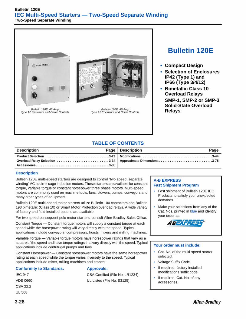
Bulletin 120E
• Compact Design• Selection of Enclosures
IP42 (Type 1) andIP66 (Type 3/4/12)
• Bimetallic Class 10Overload RelaysSMP-1, SMP-2 or SMP-3Solid-State OverloadRelays
TABLE OF CONTENTSDescription Page Description PageProduct Selection . . . . . . . . . . . . . . . . . . . . . . . . . . . . . . . . . . . . 3-29Overload Relay Selection. . . . . . . . . . . . . . . . . . . . . . . . . . . . . . 3-34Accessories. . . . . . . . . . . . . . . . . . . . . . . . . . . . . . . . . . . . . . . . . 3-38
Modifications . . . . . . . . . . . . . . . . . . . . . . . . . . . . . . . . . . . . . . . .3-44Approximate Dimensions . . . . . . . . . . . . . . . . . . . . . . . . . . . . . .3-75
Description
Bulletin 120E multi-speed starters are designed to control “two speed, separatewinding” AC squirrel cage induction motors. These starters are available for constanttorque, variable torque or constant horsepower three phase motors. Multi-speedmotors are commonly used on machine tools, fans, blowers, pumps, conveyors andmany other types of equipment.
A-B EXPRESSFast Shipment Program• Fast shipment of Bulletin 120E IEC
Products to satisfy your unexpecteddemands.
• Make your selections from any of theCat. Nos. printed in blue and identifyyour order as
Bulletin 120E multi-speed motor starters utilize Bulletin 100 contactors and Bulletin193 bimetallic (Class 10) or Smart Motor Protection overload relays. A wide varietyof factory and field installed options are available.
For two speed consequent pole motor starters, consult Allen-Bradley Sales Office.
Constant Torque — Constant torque motors will supply a constant torque at eachspeed while the horsepower rating will vary directly with the speed. Typicalapplications include conveyors, compressors, hoists, mixers and milling machines.
Variable Torque — Variable torque motors have horsepower ratings that vary as asquare of the speed and have torque ratings that vary directly with the speed. Typicalapplications include centrifugal pumps and fans. Your order must include:
• Cat. No. of the multi-speed starterselected.
• Voltage Suffix Code.
• If required, factory installedmodifications suffix code.
• If required, Cat. No. of anyaccessories.
Constant Horsepower — Constant horsepower motors have the same horsepowerrating at each speed while the torque varies inversely to the speed. Typicalapplications include mixer, milling machines and cranes.
Conformity to Standards: App rovals:
IEC 947 CSA Certified (File No. LR1234)
VDE 0660 UL Listed (File No. E3125)
CSA 22.2
UL 508
Bulletin 120E, 45 AmpType 12 Enclosure and Cover Controls
Bulletin 120E, 45 AmpType 12 Enclosure and Cover Controls
Bulletin 120EIEC Multi-Speed Starters
3-29
Product Selection
Enclosed Type
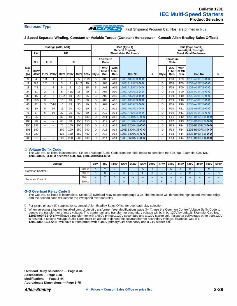
2 Speed Separate Winding, Constant or Variable Torque (Constant Horsepower —Consult Allen -Bradley Sales Office.)
⊗ Voltage Suffix CodeThe Cat. No. as listed is incomplete. Select a Voltage Suffix Code from the table below to complete the Cat. No. Example: Cat. No.120E-A09A⊗3-- becomes Cat. No. 120E-A09AB3- -.
- Overload Relay Code ➊The Cat. No. as listed is incomplete. Select (2) overload relay codes from page 3-34.The first code will denote the high speed overload relay,and the second code will denote the low speed overload relay.
➊ For single phase (1∅) applications, consult Allen-Bradley Sales Office for overload relay selection.➋ When selecting a factory installed control circuit transformer (see Modifications page 3-44), use the Common Control Voltage Suffix Code to
denote the transformer primary voltage. The starter coil and transformer secondary voltage will both be 120V by default. Example: Cat. No.120E-A09FB3--6P will have a transformer with a 480V primary/120V secondary and a 120V starter coil. If a starter coil voltage other than 120Vis desired, a second Voltage Suffix Code must be added to denote the coil/transformer secondary voltage. Example: Cat. No.120E-A09FBJ3- -6P will have a transformer with a 480V primary/24V secondary and a 24V starter coil.
Ratings (AC3, AC4) IP42 (Type 1)General Purpose
Sheet Metal Enclosure
IP66 (Type 3/4/12)Watertight, Dusttight
Sheet Metal Enclosure
MaxIe(A)
kW HP
3∅ 1∅ ➊ 3∅Enclosure
Code
Cat. No.
EnclosureCode
Cat. No. 380V/ 415V 115V 230V 200V 230V 460V 575V Style
W/OXFMR Dim.
WithXFMR Dim. Style
W/OXFMR Dim.
WithXFMR Dim.
9 4 1/3 1 2 2 5 7-1/2 B A08 A09 120E-A09A⊗3-- D F08 F09 120E-A09F⊗3--
12 5.5 1/2 2 3 3 7-1/2 10 B A08 A09 120E-A12A⊗3-- D F08 F09 120E-A12F⊗3--
18 7.5 1 3 5 5 10 15 B A08 A09 120E-A18A⊗3-- D F08 F09 120E-A18F⊗3--
24 11 2 3 5 7-1/2 15 20 B A08 A09 120E-A24A⊗3-- D F08 F09 120E-A24F⊗3--
30 15 2 5 7-1/2 10 20 25 B A09 A10 120E-A30A⊗3-- D F09 F10 120E-A30F⊗3--
38 18.5 3 5 10 10 25 30 B A09 A10 120E-A38A⊗3-- D F09 F10 120E-A38F⊗3--
45 22 3 7-1/2 10 15 30 40 B A09 A10 120E-A45A⊗3-- D F09 F10 120E-A45F⊗3--
60 30 5 10 15 20 40 50 B A10 A11 120E-A60A⊗3-- D F10 F11 120E-A60F⊗3--
75 37 5 10 20 25 50 60 B A10 A11 120E-A75A⊗3-- D F10 F11 120E-A75F⊗3--
110 55 – – 30 40 75 100 D A11 A12 120E-B110A⊗3-- D F11 F12 120E-B110F⊗3--
180 90 – – 60 60 150 150 D A12 A13 120E-B180A⊗3-- D F12 F13 120E-B180F⊗3--
250 132 – – 75 100 200 250 D A13 A14 120E-B250A⊗3-- D F13 F14 120E-B250F⊗3--
303 160 – – 100 100 250 300 D A13 A14 120E-B300A⊗3-- D F13 F14 120E-B300F⊗3--
414 220 – – 125 150 350 400 D A13 A14 120E-B400A⊗3-- D F13 F14 120E-B400F⊗3--
608 315 – – 300 250 500 600 D A14 A14 120E-B600A⊗3-- D F14 F14 120E-B600F⊗3--
Voltage 24V 48V 110V 120V 208V 220V 240V 277V 380V 415V 440V 480V 500V 600V
Common Control ➋50 Hz K Y D – – A T – N I B – M –
60 Hz J X – D H L A – – – G B – C
Separate Control50 Hz K Y D – – – – – – – – – – –
60 Hz J X – D – – – F – – – – – –
Fast Shipment Program Cat. Nos. are printed in blue.
Overload Relay Selections — Page 3-34Accessories — Page 3-38Modifications — Page 3-44Approximate Dimensions — Page 3-75
Prices – Consult Sales Office or price list
Bulletin 132IEC Pump Control Panels
3-30
3Fusible Disconnect Type
Bulletin 132
• IP32 (Type 3R)• Bimetallic Class 10
Overload Relays• SMP-1, SMP-2 or SMP-3
Solid-State OverloadRelays
• Enclosure with ExtraPanel Space forMounting AccessoryDevices
TABLE OF CONTENTSDescription Page Description Page
Product Selection . . . . . . . . . . . . . . . . . . . . . . . . . . . . . . . . . . . . 3-31Overload Relay Selection. . . . . . . . . . . . . . . . . . . . . . . . . . . . . . 3-34Accessories. . . . . . . . . . . . . . . . . . . . . . . . . . . . . . . . . . . . . . . . . 3-38
Modifications . . . . . . . . . . . . . . . . . . . . . . . . . . . . . . . . . . . . . . . .3-44
Approximate Dimensions . . . . . . . . . . . . . . . . . . . . . . . . . . . . . .3-75
Description
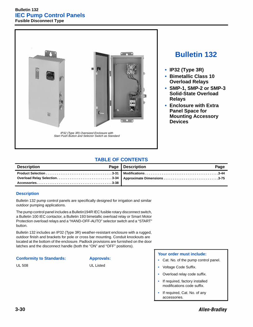
Bulletin 132 pump control panels are specifically designed for irrigation and similaroutdoor pumping applications.
The pump control panel includes a Bulletin194R IEC fusible rotary disconnect switch,a Bulletin 100 IEC contactor, a Bulletin 193 bimetallic overload relay or Smart MotorProtection overload relays and a “HAND-OFF-AUTO” selector switch and a “START”button.
Bulletin 132 includes an IP32 (Type 3R) weather-resistant enclosure with a rugged,outdoor finish and brackets for pole or cross bar mounting. Conduit knockouts arelocated at the bottom of the enclosure. Padlock provisions are furnished on the doorlatches and the disconnect handle (both the “ON” and “OFF” positions).
Your order must include:• Cat. No. of the pump control panel.
• Voltage Code Suffix.
• Overload relay code suffix.
• If required, factory installedmodifications code suffix.
• If required, Cat. No. of anyaccessories.
Conformity to Standards: App rovals:
UL 508 UL Listed
IP32 (Type 3R) Oversized Enclosure withStart Push Button and Selector Switch as Standard
Bulletin 132IEC Pump Control Panels
3-31
Product Selection
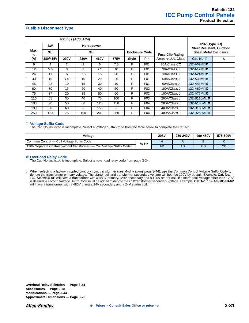
Fusible Disconnect Type
⊗ Voltage Suffix CodeThe Cat. No. as listed is incomplete. Select a Voltage Suffix Code from the table below to complete the Cat. No.
Overload Relay CodeThe Cat. No. as listed is incomplete. Select an overload relay code from page 3-34.
➊ When selecting a factory installed control circuit transformer (see Modifications page 3-44), use the Common Control Voltage Suffix Code todenote the transformer primary voltage. The starter coil and transformer secondary voltage will both be 120V by default. Example: Cat. No.132-A09MB-6P will have a transformer with a 480V primary/120V secondary and a 120V starter coil. If a starter coil voltage other than 120Vis desired, a second Voltage Suffix Code must be added to denote the coil/transformer secondary voltage. Example: Cat. No. 132-A09MBJ -6Pwill have a transformer with a 480V primary/24V secondary and a 24V starter coil.
Ratings (AC3, AC4)
Enclosure CodeFuse Clip Rating
Amperes/UL Class
IP32 (Type 3R)Sleet Resistant, OutdoorSheet Metal EnclosureMax.
Ie(A)
kW Horsepower
3∅ 3∅
380/415V 200V 230V 460V 575V Style Pin Cat. No. ➊
9 4 2 2 5 7.5 F F01 30A/Class CC 132-A09M⊗
12 5.5 3 3 7.5 10 F F01 30A/Class J 132-A12M⊗
24 11 5 7.5 15 20 F F01 30A/Class J 132-A24M⊗
30 15 7.5 10 20 25 F F01 60A/Class J 132-A30M⊗
45 22 10 15 30 40 F F01 60A/Class J 132-A45M⊗
60 30 15 20 40 50 F F02 100A/Class J 132-A60M⊗
75 37 20 25 50 60 F F02 100A/Class J 132-A75M⊗
110 55 30 40 75 100 F F03 200A/Class J 132-B110M⊗
180 90 50 60 126 150 F F04 200A/Class J 132-A180M⊗
180 90 60 – 150 – F F04 400A/Class J 132-B180M⊗
250 132 75 100 200 250 F F04 400A/Class J 132-B250M⊗
Voltage 208V 230-240V 460-480V 575-600V
Common Control — Coil Voltage Suffix Code60 Hz
H A B C
120V Separate Control (without transformer) — Coil Voltage Suffix Code AD AD CD CD
Overload Relay Selection — Page 3-34Accessories — Page 3-38Modifications — Page 3-44Approximate Dimensions — Page 3-75
Prices – Consult Sales Office or price list
Bulletin 133IEC Pump Control Panels
3-32
3Circuit Breaker Type
Bulletin 133
• IP32 (Type 3R)• Bimetallic Class 10
Overload Relays• SMP-1, SMP-2 or SMP-3
Solid-State OverloadRelays
• Enclosure with ExtraPanel Space forMounting AccessoryDevices
TABLE OF CONTENTSDescription Page Description Page
Product Selection . . . . . . . . . . . . . . . . . . . . . . . . . . . . . . . . . . . . 3-33Overload Relay Selection. . . . . . . . . . . . . . . . . . . . . . . . . . . . . . 3-34Accessories. . . . . . . . . . . . . . . . . . . . . . . . . . . . . . . . . . . . . . . . . 3-38
Modifications . . . . . . . . . . . . . . . . . . . . . . . . . . . . . . . . . . . . . . . .3-44Approximate Dimensions . . . . . . . . . . . . . . . . . . . . . . . . . . . . . .3-75
Description
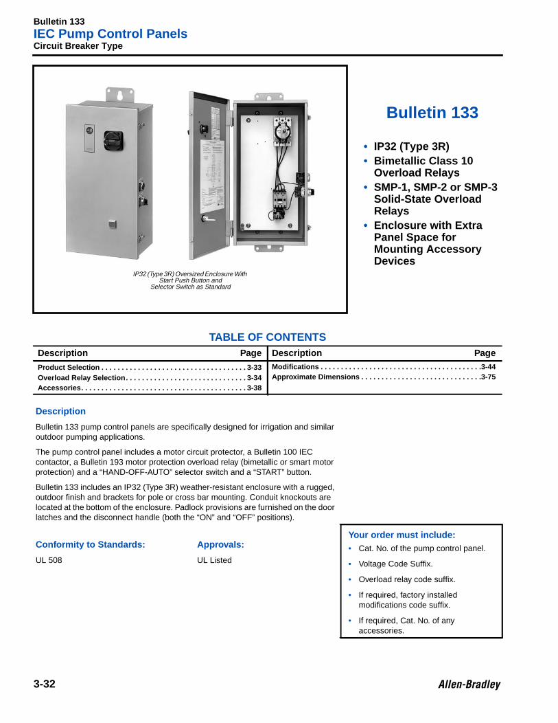
Bulletin 133 pump control panels are specifically designed for irrigation and similaroutdoor pumping applications.
The pump control panel includes a motor circuit protector, a Bulletin 100 IECcontactor, a Bulletin 193 motor protection overload relay (bimetallic or smart motorprotection) and a “HAND-OFF-AUTO” selector switch and a “START” button.
Bulletin 133 includes an IP32 (Type 3R) weather-resistant enclosure with a rugged,outdoor finish and brackets for pole or cross bar mounting. Conduit knockouts arelocated at the bottom of the enclosure. Padlock provisions are furnished on the doorlatches and the disconnect handle (both the “ON” and “OFF” positions).
Your order must include:• Cat. No. of the pump control panel.
• Voltage Code Suffix.
• Overload relay code suffix.
• If required, factory installedmodifications code suffix.
• If required, Cat. No. of anyaccessories.
Conformity to Standards: App rovals:
UL 508 UL Listed
IP32 (Type 3R) Oversized Enclosure WithStart Push Button and
Selector Switch as Standard
Bulletin 133IEC Pump Control Panels
3-33
Product Selection
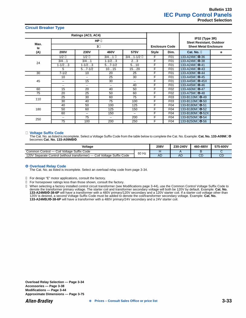
Circuit Breaker Type
⊗ Voltage Suffix CodeThe Cat. No. as listed is incomplete. Select a Voltage Suffix Code from the table below to complete the Cat. No. Example: Cat. No. 133-A09M ⊗becomes Cat. No. 133-A09MB .
Overload Relay CodeThe Cat. No. as listed is incomplete. Select an overload relay code from page 3-34.
➊ For design “E” motor applications, consult the factory.➋ For horsepower ratings less than those shown, consult the factory.➌ When selecting a factory installed control circuit transformer (see Modifications page 3-44), use the Common Control Voltage Suffix Code to
denote the transformer primary voltage. The starter coil and transformer secondary voltage will both be 120V by default. Example: Cat. No.133-A24MB-38-6P will have a transformer with a 480V primary/120V secondary and a 120V starter coil. If a starter coil voltage other than120V is desired, a second Voltage Suffix Code must be added to denote the coil/transformer secondary voltage. Example: Cat. No.133-A24MBJ -38-6P will have a transformer with a 480V primary/24V secondary and a 24V starter coil.
Ratings (AC3, AC4)
Enclosure Code
IP32 (Type 3R)Sleet Resistant, OutdoorSheet Metal Enclosure
Max.Ie(A)
HP ➊
3∅
200V 230V 460V 575V Style Dim. Cat. No. ➌
24
1/2 ➋ 1/2 ➋ 3/4…1 ➋ 3/4…1-1/2 ➋ F F01 133-A24M⊗-363/4…1 3/4…1 1-1/2…3 2…3 F F01 133-A24M⊗-38
1-1/2…3 1-1/2…3 5…7-1/2 5…10 F F01 133-A24M⊗-415 5…7-1/2 10…15 15…20 F F01 133-A24M⊗-43
30 7-1/2 10 20 25 F F01 133-A30M⊗-44
4510 – 25 30 F F01 133-A45M⊗-45– 15 30 – F F01 133-A45M⊗-45X– – – 40 F F01 133-A45M⊗-46
60 15 20 40 50 F F02 133-A60M⊗-4775 20 25 50 60 F F02 133-A75M⊗-48
11025 30 60 75 F F03 133-B110M⊗-4930 40 75 100 F F03 133-B110M⊗-50
18040 50 100 125 F F04 133-B180M⊗-5150 60 125 150 F F04 133-B180M⊗-5260 – 150 – F F04 133-B180M⊗-52X
250– 75 – 200 F F04 133-B250M⊗-5475 100 200 250 F F04 133-B250M⊗-56
Voltage 208V 230-240V 460-480V 575-600V
Common Control — Coil Voltage Suffix Code60 Hz
H A B C120V Separate Control (without transformer) — Coil Voltage Suffix Code AD AD CD CD
Overload Relay Selection — Page 3-34Accessories — Page 3-38Modifications — Page 3-44Approximate Dimensions — Page 3-75
Prices – Consult Sales Office or price list
Bulletin 100 LineOverload Relay Code Selection
3-34
3Overload Relay Selection
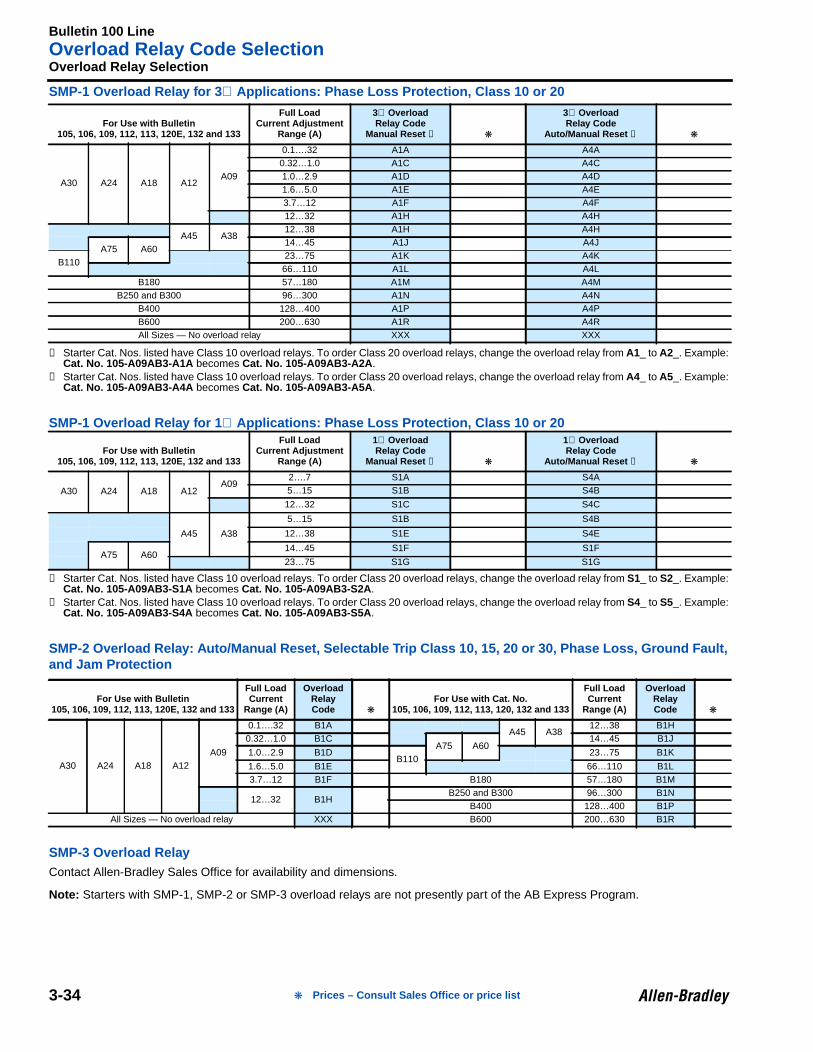
SMP-1 Overload Relay for 3 ∅ Applications: Phase Loss Protection, Class 10 or 20
➊ Starter Cat. Nos. listed have Class 10 overload relays. To order Class 20 overload relays, change the overload relay from A1_ to A2_. Example:Cat. No. 105-A09AB3-A1A becomes Cat. No. 105-A09AB3-A2A .
➋ Starter Cat. Nos. listed have Class 10 overload relays. To order Class 20 overload relays, change the overload relay from A4_ to A5_. Example:Cat. No. 105-A09AB3-A4A becomes Cat. No. 105-A09AB3-A5A .
SMP-1 Overload Relay for 1 ∅ Applications: Phase Loss Protection, Class 10 or 20
➊ Starter Cat. Nos. listed have Class 10 overload relays. To order Class 20 overload relays, change the overload relay from S1_ to S2_. Example:Cat. No. 105-A09AB3-S1A becomes Cat. No. 105-A09AB3-S2A .
➋ Starter Cat. Nos. listed have Class 10 overload relays. To order Class 20 overload relays, change the overload relay from S4_ to S5_. Example:Cat. No. 105-A09AB3-S4A becomes Cat. No. 105-A09AB3-S5A .
SMP-2 Overload Relay: Auto/Manual Reset, Selectable Trip Class 10, 15, 20 or 30, Phase Loss, Ground Fault,and Jam Protection
SMP-3 Overload RelayContact Allen-Bradley Sales Office for availability and dimensions.
Note: Starters with SMP-1, SMP-2 or SMP-3 overload relays are not presently part of the AB Express Program.
For Use with Bulletin105, 106, 109, 112, 113, 120E, 132 and 133
Full LoadCurrent Adjustment
Range (A)
3∅ OverloadRelay Code
Manual Reset ➊
3∅ OverloadRelay Code
Auto/Manual Reset ➋
A30 A24 A18 A12A09
0.1….32 A1A A4A0.32…1.0 A1C A4C1.0…2.9 A1D A4D1.6…5.0 A1E A4E3.7…12 A1F A4F12…32 A1H A4H
A45 A3812…38 A1H A4H
A75 A6014…45 A1J A4J
B11023…75 A1K A4K66…110 A1L A4L
B180 57…180 A1M A4MB250 and B300 96…300 A1N A4N
B400 128…400 A1P A4PB600 200…630 A1R A4RAll Sizes — No overload relay XXX XXX
For Use with Bulletin105, 106, 109, 112, 113, 120E, 132 and 133
Full LoadCurrent Adjustment
Range (A)
1∅ OverloadRelay Code
Manual Reset ➊
1∅ OverloadRelay Code
Auto/Manual Reset ➋
A30 A24 A18 A12A09
2….7 S1A S4A5…15 S1B S4B
12…32 S1C S4C
A45 A38
5…15 S1B S4B
12…38 S1E S4E
A75 A6014…45 S1F S1F
23…75 S1G S1G
For Use with Bulletin105, 106, 109, 112, 113, 120E, 132 and 133
Full LoadCurrent
Range (A)
OverloadRelayCode
For Use with Cat. No.105, 106, 109, 112, 113, 120, 132 and 133
Full LoadCurrent
Range (A)
OverloadRelayCode
A30 A24 A18 A12A09
0.1….32 B1AA45 A38
12…38 B1H0.32…1.0 B1C
A75 A6014…45 B1J
1.0…2.9 B1DB110
23…75 B1K
1.6…5.0 B1E 66…110 B1L3.7…12 B1F B180 57…180 B1M
12…32 B1HB250 and B300 96…300 B1N
B400 128…400 B1PAll Sizes — No overload relay XXX B600 200…630 B1R
Prices – Consult Sales Office or price list
Bulletin 100 LineOverload Relay Code Selection
3-35
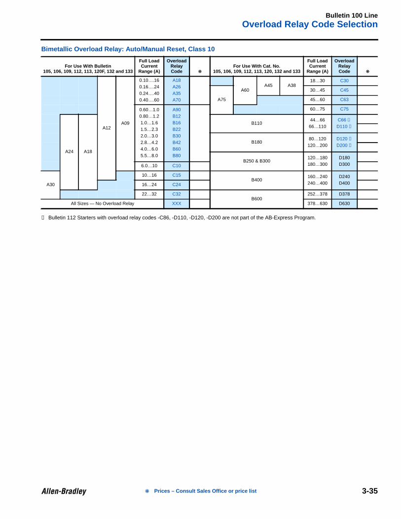
Bimetallic Overload Relay: Auto/Manual Reset, Class 10
➊ Bulletin 112 Starters with overload relay codes -C86, -D110, -D120, -D200 are not part of the AB-Express Program.
For Use With Bulletin105, 106, 109, 112, 113, 120F, 132 and 133
Full LoadCurrent
Range (A)
OverloadRelayCode
For Use With Cat. No.105, 106, 109, 112, 113, 120, 132 and 133
Full LoadCurrent
Range (A)
OverloadRelayCode
A12A09
0.10….160.16….240.24….400.40….60
A18A26A35A70
A60A45 A38
18…30 C30
A75
30…45 C45
45…60 C63
0.60…1.00.80…1.21.0…1.61.5…2.32.0…3.02.8…4.24.0…6.05.5…8.0
A90B12B16B22B30B42B60B80
60…75 C75
A24 A18
B11044…6666…110
C66 ➊
D110 ➊
B18080…120
120…200D120 ➊
D200 ➊
B250 & B300120…180180…300
D180D3006.0…10 C10
A30
10…16 C15B400
160…240240…400
D240D40016…24 C24
22…32 C32B600
252…378 D378
All Sizes — No Overload Relay XXX 378…630 D630
Prices – Consult Sales Office or price list
Bulletin 198EIEC Enclosures
3-36
3Product Selection
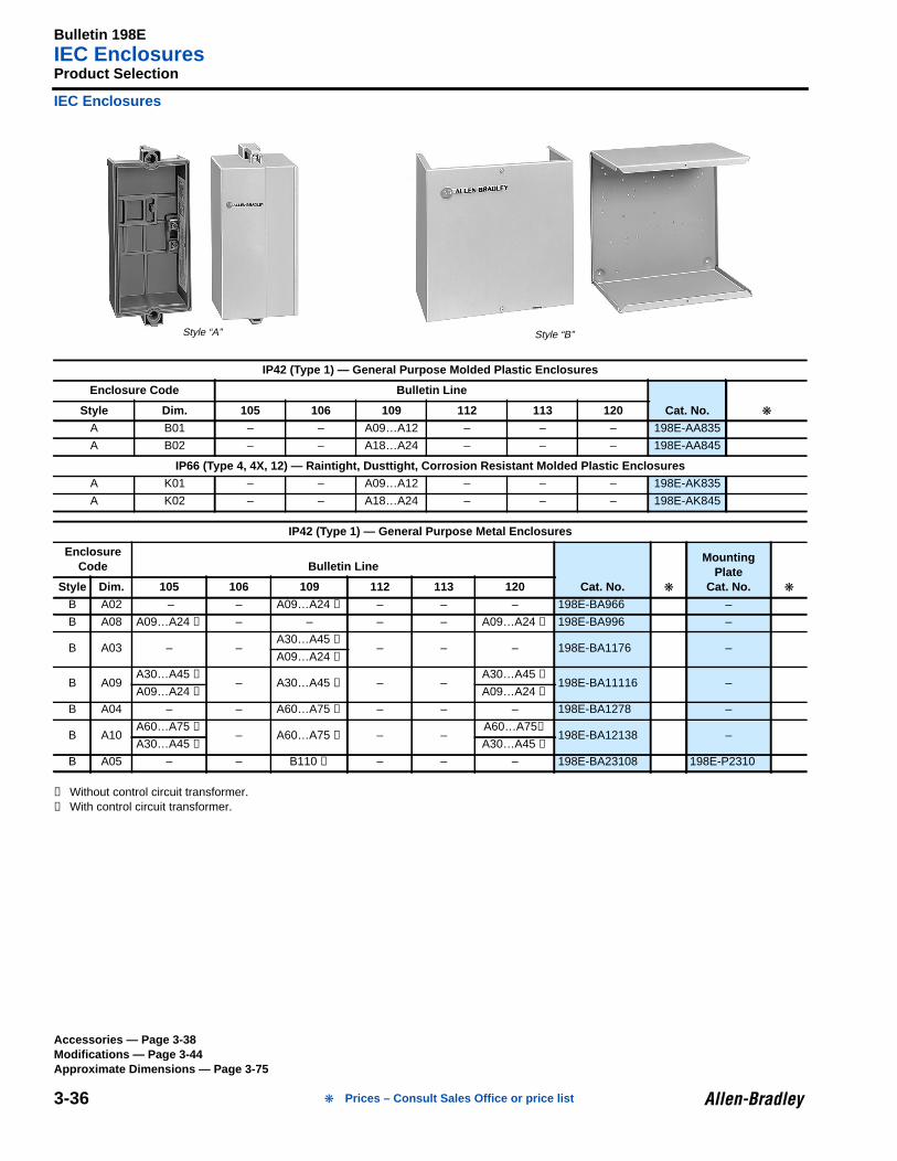
IEC Enclosures
➊ Without control circuit transformer.➋ With control circuit transformer.
IP42 (Type 1) — General Purpose Molded Plastic Enclosures
Enclosure Code Bulletin Line
Cat. No. Style Dim. 105 106 109 112 113 120A B01 – – A09…A12 – – – 198E-AA835
A B02 – – A18…A24 – – – 198E-AA845
IP66 (Type 4, 4X, 12) — Raintight, Dusttight, Corrosion Resistant Molded Plastic EnclosuresA K01 – – A09…A12 – – – 198E-AK835
A K02 – – A18…A24 – – – 198E-AK845
IP42 (Type 1) — General Purpose Metal Enclosures
EnclosureCode Bulletin Line
Cat. No.
MountingPlate
Cat. No. Style Dim. 105 106 109 112 113 120B A02 – – A09…A24 ➊ – – – 198E-BA966 –
B A08 A09…A24 ➊ – – – – A09…A24 ➊ 198E-BA996 –
B A03 – –A30…A45 ➊
– – – 198E-BA1176 –A09…A24 ➋
B A09A30…A45 ➊
– A30…A45 ➋ – –A30…A45 ➊
198E-BA11116 –A09…A24 ➋ A09…A24 ➋
B A04 – – A60…A75 ➊ – – – 198E-BA1278 –
B A10A60…A75 ➊
– A60…A75 ➋ – –A60…A75➊
198E-BA12138 –A30…A45 ➋ A30…A45 ➋
B A05 – – B110 ➊ – – – 198E-BA23108 198E-P2310
Style “A” Style “B”
Accessories — Page 3-38Modifications — Page 3-44Approximate Dimensions — Page 3-75
Prices – Consult Sales Office or price list
Bulletin 198EIEC Enclosures
3-37
Product Selection, Continued
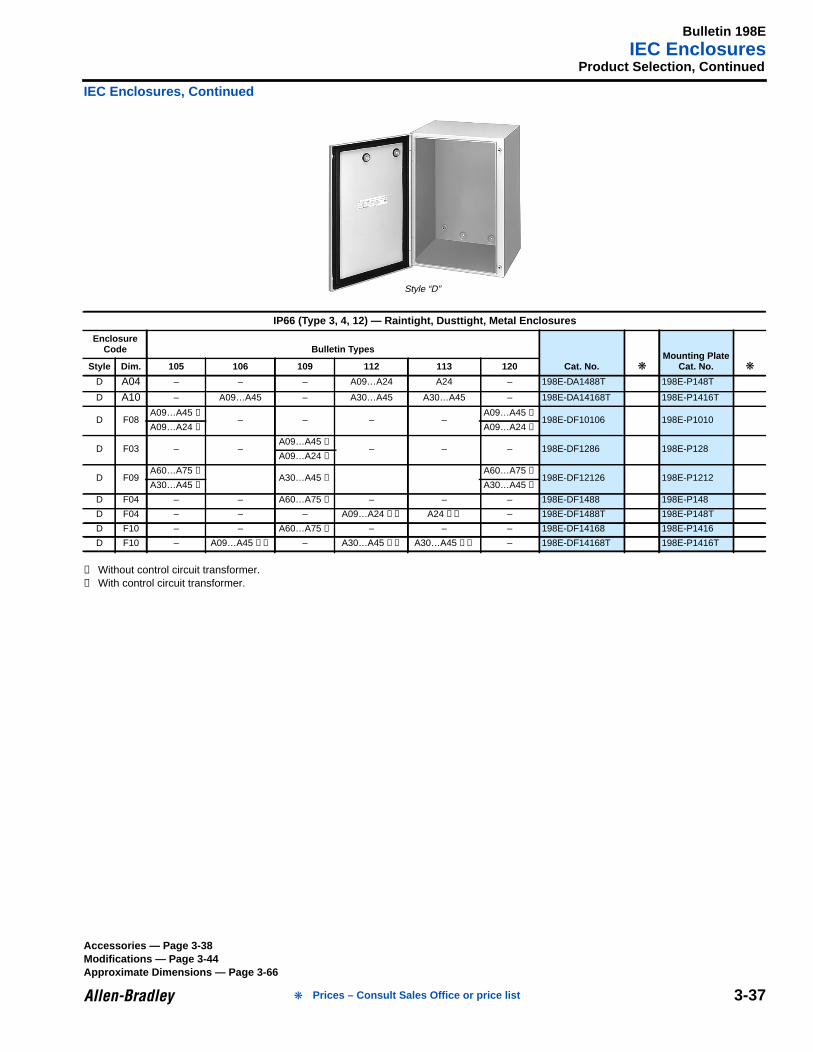
IEC Enclosures, Continued
➊ Without control circuit transformer.➋ With control circuit transformer.
IP66 (Type 3, 4, 12) — Raintight, Dusttight, Metal Enclosures
EnclosureCode Bulletin Types
Cat. No. Mounting Plate
Cat. No. Style Dim. 105 106 109 112 113 120
D A04 – – – A09…A24 A24 – 198E-DA1488T 198E-P148T
D A10 – A09…A45 – A30…A45 A30…A45 – 198E-DA14168T 198E-P1416T
D F08A09…A45 ➊
– – – –A09…A45 ➊
198E-DF10106 198E-P1010A09…A24 ➋ A09…A24 ➋
D F03 – –A09…A45 ➊
– – – 198E-DF1286 198E-P128A09…A24 ➋
D F09A60…A75 ➊
A30…A45 ➋A60…A75 ➊
198E-DF12126 198E-P1212A30…A45 ➋ A30…A45 ➋
D F04 – – A60…A75 ➊ – – – 198E-DF1488 198E-P148
D F04 – – – A09…A24 ➊➋ A24 ➊➋ – 198E-DF1488T 198E-P148T
D F10 – – A60…A75 ➋ – – – 198E-DF14168 198E-P1416
D F10 – A09…A45 ➊➋ – A30…A45 ➊➋ A30…A45 ➊➋ – 198E-DF14168T 198E-P1416T
Style “D”
Accessories — Page 3-38Modifications — Page 3-44Approximate Dimensions — Page 3-66
Prices – Consult Sales Office or price list
Bulletin 100 LineAccessories — Field Installed
3-38
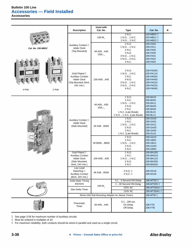
3Accessories
➊ See page 3-56 for maximum number of auxiliary circuits.➋ Must be ordered in multiples of 10.➌ For maximum reliability, both contacts should be wired in parallel and used as a single circuit.
DescriptionUsed withCat. No. Type Cat. No.
Auxiliary Contact ➊
Adder Deck(Top Mounted)
100-M_2 N.C.
1 N.O.…1 N.C.2 N.O.…2 N.C
193-MB02 ➋
193-MB11 ➋
193-MB22 ➋
All A09…A45100L-_
2 N.O.1 N.O.…1 N.C.
2 N.C.4 N.O.
3 N.O.…1 N.C.2 N.O.…2 N.C.
4 N.C.
195-FA20195-FA11195-FA02195-FA40195-FA31195-FA22195-FA04
Gold Plated ➊
Auxiliary ContactAdder Deck
(Top Mounted, 8mA,24V min.)
100-A09…A45
2 N.O.1 N.O.…1 N.C.
2 N.C.4 N.O.
3 N.O.…1 N.C.2 N.O.…2 N.C.
4 N.C.
195-FA20G195-FA11G195-FA02G195-FA40G195-FA31G195-FA22G195-FA04G
Auxiliary Contact ➊
Adder Deck(Side Mounted)
All A09…A30100L-_
1 N.O.1 N.C.
1 N.O.…1 N.C.2 N.O.2 N.C.
1 N.C. (Late Break)1 N.O.…1 N.C. (Late Break)
195-BA10195-BA01195-BA11195-BA20195-BA02195-BL01195-BL11
All A38…B300
1 N.O.1 N.C.
1 N.O.…1 N.C.2 N.O.2 N.C.
1 N.C. (Late Break)
195-GA10195-GA01195-GA11195-GA20195-GA02195-GL01
All B400…B600
1 N.O.1 N.C.
1 N.O.…1 N.C.2 N.O.2 N.C.
195-GA10195-GB01195-GB11195-GA20195-GB02
Gold Plated ➊
Auxiliary ContactAdder Deck
(Side Mounted,8mA, 24V min.)
100-A09…A30
1 N.O.1 N.C.
1 N.O.…1 N.C.2 N.O.2 N.C.
195-BA10G195-BA01G195-BA11G195-BA20G195-BA02G
Low LevelSwitching ➊
Auxiliary Contact(8mA, 24V min.)
All A38…B3002 N.O. ➌
2 N.C. ➌
195-NX19195-NX18
Solid-State TimingElement
100-M_
0.1…3 Second ON-Delay 196-MT3S ➋
1…30 Second ON-Delay 196-MT30S ➋
Star-Delta Timer220V AC 196-MTSDA2 ➋
110V AC 196-MTSDA1 ➋
35mm DIN Rail Mounting Adapter for Above Timers 196-MTM ➋
PneumaticTimer
All A09…A450.1…180 sec
On DelayOff Delay
196-FTA196-FTB
4-Pole 2-Pole
Cat. No. 195-MB22
Prices – Consult Sales Office or price list
Bulletin 100 LineAccessories — Field Installed
3-39
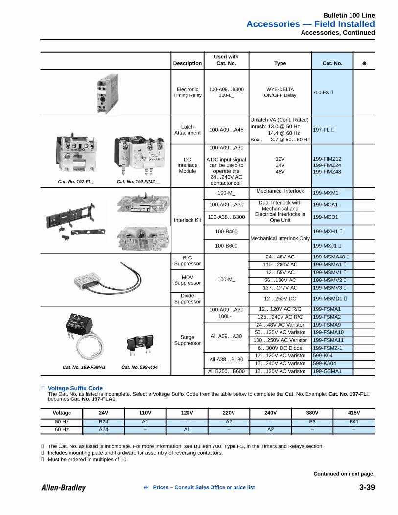
Accessories, Continued
⊗ Voltage Suffix CodeThe Cat. No. as listed is incomplete. Select a Voltage Suffix Code from the table below to complete the Cat. No. Example: Cat. No. 197-FL ⊗becomes Cat. No. 197-FLA1 .
➊ The Cat. No. as listed is incomplete. For more information, see Bulletin 700, Type FS, in the Timers and Relays section.➋ Includes mounting plate and hardware for assembly of reversing contactors.➌ Must be ordered in multiples of 10.
DescriptionUsed withCat. No. Type Cat. No.
ElectronicTiming Relay
100-A09…B300100-L_
WYE-DELTAON/OFF Delay
700-FS ➊
LatchAttachment 100-A09…A45
Unlatch VA (Cont. Rated)Inrush: 13.0 @ 50 Hz
14.4 @ 60 HzSeal: 3.7 @ 50…60 Hz
197-FL ⊗
DCInterfaceModule
100-A09…A30
A DC input signalcan be used to
operate the24…240V ACcontactor coil
12V24V48V
199-FIMZ12199-FlMZ24199-FlMZ48
Interlock Kit
100-M_ Mechanical Interlock 199-MXM1
100-A09…A30 Dual Interlock withMechanical and
Electrical Interlocks inOne Unit
199-MCA1
100-A38…B300 199-MCD1
100-B400Mechanical Interlock Only
199-MXH1 ➋
100-B600 199-MXJ1 ➋
R-CSuppressor
100-M_
24…48V AC 199-MSMA48 ➌
110…280V AC 199-MSMA1 ➌
MOVSuppressor
12…55V AC 199-MSMV1 ➌
56…136V AC 199-MSMV2 ➌
137…277V AC 199-MSMV3 ➌
DiodeSuppressor 12…250V DC 199-MSMD1 ➌
SurgeSuppressor
100-A09…A30100L-_
12…120V AC R/C 199-FSMA1
125…240V AC R/C 199-FSMA2
All A09…A30
24…48V AC Varistor 199-FSMA9
50…125V AC Varistor 199-FSMA10
130…250V AC Varistor 199-FSMA11
6…300V DC Diode 199-FSMZ-1
All A38…B18012…120V AC Varistor 599-K04
12…240V AC Varistor 599-KA04
All B250…B600 12…120V AC Varistor 199-GSMA1
Voltage 24V 110V 120V 220V 240V 380V 415V
50 Hz B24 A1 – A2 – B3 B41
60 Hz A24 – A1 – A2 – –
Cat. No. 197-FL_ Cat. No. 199-FIMZ__
Cat. No. 199-FSMA1 Cat. No. 599-K04
Continued on next page.
Prices – Consult Sales Office or price list
Bulletin 100 LineAccessories — Field Installed
3-40
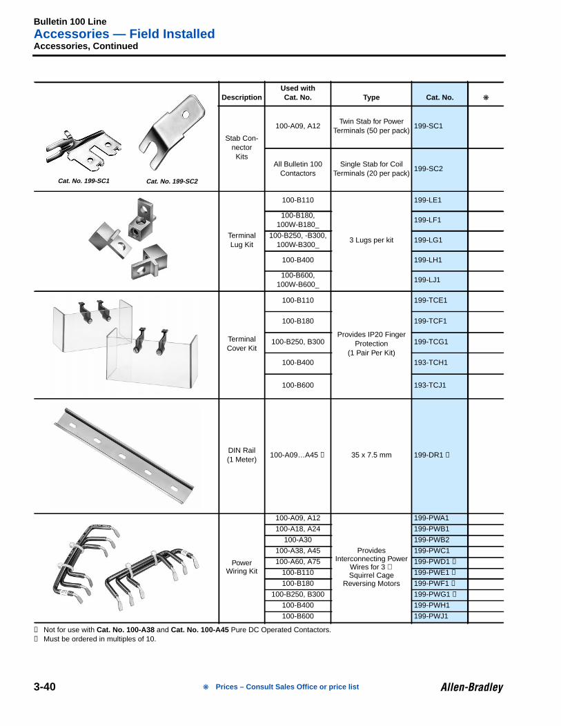
Accessories, Continued
➊ Not for use with Cat. No. 100-A38 and Cat. No. 100-A45 Pure DC Operated Contactors.➋ Must be ordered in multiples of 10.
DescriptionUsed withCat. No. Type Cat. No.
Stab Con-nector
Kits
100-A09, A12Twin Stab for Power
Terminals (50 per pack)199-SC1
All Bulletin 100Contactors
Single Stab for CoilTerminals (20 per pack)
199-SC2
TerminalLug Kit
100-B110
3 Lugs per kit
199-LE1
100-B180,100W-B180_
199-LF1
100-B250, -B300,100W-B300_
199-LG1
100-B400 199-LH1
100-B600,100W-B600_
199-LJ1
TerminalCover Kit
100-B110
Provides IP20 FingerProtection
(1 Pair Per Kit)
199-TCE1
100-B180 199-TCF1
100-B250, B300 199-TCG1
100-B400 193-TCH1
100-B600 193-TCJ1
DIN Rail(1 Meter)
100-A09…A45 ➊ 35 x 7.5 mm 199-DR1 ➋
PowerWiring Kit
100-A09, A12
ProvidesInterconnecting Power
Wires for 3 ∅Squirrel Cage
Reversing Motors
199-PWA1
100-A18, A24 199-PWB1
100-A30 199-PWB2
100-A38, A45 199-PWC1
100-A60, A75 199-PWD1 ➊
100-B110 199-PWE1 ➊
100-B180 199-PWF1 ➊
100-B250, B300 199-PWG1 ➊
100-B400 199-PWH1
100-B600 199-PWJ1
Cat. No. 199-SC1 Cat. No. 199-SC2
Prices – Consult Sales Office or price list
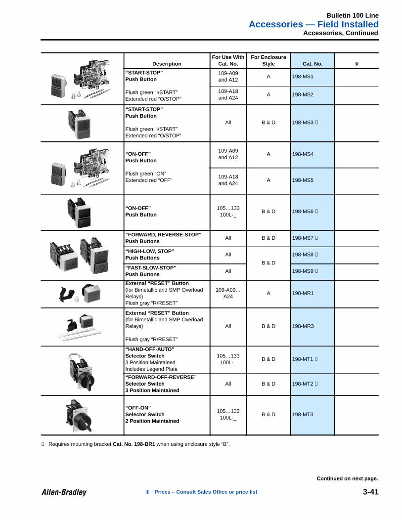
Bulletin 100 LineAccessories — Field Installed
3-41
Accessories, Continued
➊ Requires mounting bracket Cat. No. 198-BR1 when using enclosure style “B”.
DescriptionFor Use With
Cat. No.For Enclosure
Style Cat. No.
“START-STOP”Push Button
Flush green “I/START”Extended red “O/STOP”
109-A09and A12
A 198-MS1
109-A18and A24
A 198-MS2
“START-STOP”Push Button
Flush green “I/START”Extended red “O/STOP”
All B & D 198-MS3 ➊
“ON-OFF”Push Button
Flush green “ON”Extended red “OFF”
109-A09and A12
A 198-MS4
109-A18and A24
A 198-MS5
“ON-OFF”Push Button
105…133100L-_
B & D 198-MS6 ➊
“FORWARD, REVERSE-STOP”Push Buttons
All B & D 198-MS7 ➊
“HIGH-LOW, STOP”Push Buttons
All
B & D
198-MS8 ➊
“FAST-SLOW-STOP”Push Buttons
All 198-MS9 ➊
External “RESET” Button(for Bimetallic and SMP OverloadRelays)Flush gray “R/RESET”
109-A09…A24
A 198-MR1
External “RESET” Button(for Bimetallic and SMP OverloadRelays)
Flush gray “R/RESET”
All B & D 198-MR3
“HAND-OFF-AUTO”Selector Switch3 Position MaintainedIncludes Legend Plate
105…133100L-_
B & D 198-MT1 ➊
“FORWARD-OFF-REVERSE”Selector Switch3 Position Maintained
All B & D 198-MT2 ➊
“OFF-ON”Selector Switch2 Position Maintained
105…133100L-_
B & D 198-MT3
Continued on next page.
Prices – Consult Sales Office or price list
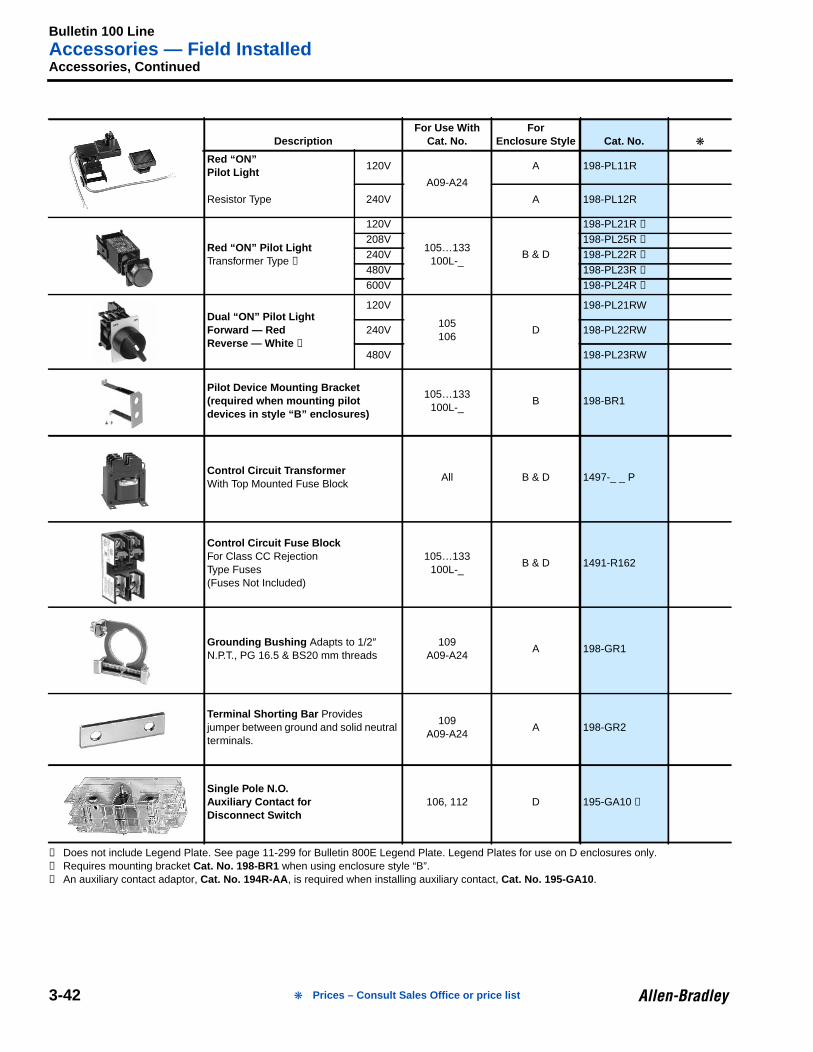
Bulletin 100 LineAccessories — Field Installed
3-42
Accessories, Continued
➊ Does not include Legend Plate. See page 11-299 for Bulletin 800E Legend Plate. Legend Plates for use on D enclosures only.➋ Requires mounting bracket Cat. No. 198-BR1 when using enclosure style “B”.➌ An auxiliary contact adaptor, Cat. No. 194R-AA , is required when installing auxiliary contact, Cat. No. 195-GA10 .
DescriptionFor Use With
Cat. No.For
Enclosure Style Cat. No.
Red “ON”Pilot Light
120V
A09-A24
A 198-PL11R
Resistor Type 240V A 198-PL12R
Red “ON” Pilot LightTransformer Type ➊
120V
105…133100L-_
B & D
198-PL21R ➋
208V 198-PL25R ➋
240V 198-PL22R ➋
480V 198-PL23R ➋
600V 198-PL24R ➋
Dual “ON” Pilot LightForward — RedReverse — White ➊
120V
105106
D
198-PL21RW
240V 198-PL22RW
480V 198-PL23RW
Pilot Device Mounting Bracket(required when mounting pilotdevices in style “B” enclosures)
105…133100L-_
B 198-BR1
Control Circuit TransformerWith Top Mounted Fuse Block
All B & D 1497-_ _ P
Control Circuit Fuse BlockFor Class CC RejectionType Fuses(Fuses Not Included)
105…133100L-_
B & D 1491-R162
Grounding Bushing Adapts to 1/2″N.P.T., PG 16.5 & BS20 mm threads
109A09-A24
A 198-GR1
Terminal Shorting Bar Providesjumper between ground and solid neutralterminals.
109A09-A24
A 198-GR2
Single Pole N.O.Auxiliary Contact forDisconnect Switch
106, 112 D 195-GA10 ➌
Prices – Consult Sales Office or price list
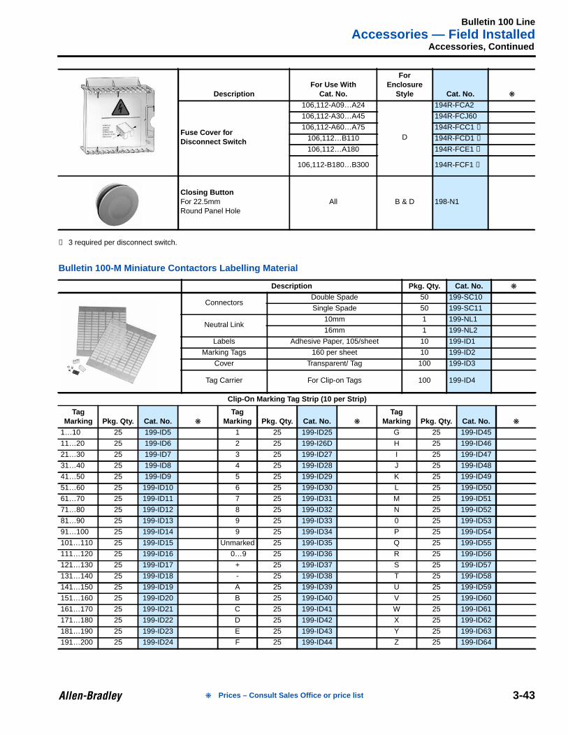
Bulletin 100 LineAccessories — Field Installed
3-43
Accessories, Continued
➊ 3 required per disconnect switch.
Bulletin 100-M Miniature Contactors Labelling Material
DescriptionFor Use With
Cat. No.
ForEnclosure
Style Cat. No.
Fuse Cover forDisconnect Switch
106,112-A09…A24
D
194R-FCA2
106,112-A30…A45 194R-FCJ60
106,112-A60…A75 194R-FCC1 ➊
106,112…B110 194R-FCD1 ➊
106,112…A180 194R-FCE1 ➊
106,112-B180…B300 194R-FCF1 ➊
Closing ButtonFor 22.5mmRound Panel Hole
All B & D 198-N1
Description Pkg. Qty. Cat. No.
ConnectorsDouble Spade 50 199-SC10
Single Spade 50 199-SC11
Neutral Link10mm 1 199-NL1
16mm 1 199-NL2
Labels Adhesive Paper, 105/sheet 10 199-ID1
Marking Tags 160 per sheet 10 199-ID2
Cover Transparent/ Tag 100 199-ID3
Tag Carrier For Clip-on Tags 100 199-ID4
Clip-On Marking Tag Strip (10 per Strip)
TagMarking Pkg. Qty. Cat. No.
TagMarking Pkg. Qty. Cat. No.
TagMarking Pkg. Qty. Cat. No.
1…10 25 199-ID5 1 25 199-ID25 G 25 199-ID45
11…20 25 199-ID6 2 25 199-I26D H 25 199-ID46
21…30 25 199-ID7 3 25 199-ID27 I 25 199-ID47
31…40 25 199-ID8 4 25 199-ID28 J 25 199-ID48
41…50 25 199-ID9 5 25 199-ID29 K 25 199-ID49
51…60 25 199-ID10 6 25 199-ID30 L 25 199-ID50
61…70 25 199-ID11 7 25 199-ID31 M 25 199-ID51
71…80 25 199-ID12 8 25 199-ID32 N 25 199-ID52
81…90 25 199-ID13 9 25 199-ID33 0 25 199-ID53
91…100 25 199-ID14 9 25 199-ID34 P 25 199-ID54
101…110 25 199-ID15 Unmarked 25 199-ID35 Q 25 199-ID55
111…120 25 199-ID16 0…9 25 199-ID36 R 25 199-ID56
121…130 25 199-ID17 + 25 199-ID37 S 25 199-ID57
131…140 25 199-ID18 - 25 199-ID38 T 25 199-ID58
141…150 25 199-ID19 A 25 199-ID39 U 25 199-ID59
151…160 25 199-ID20 B 25 199-ID40 V 25 199-ID60
161…170 25 199-ID21 C 25 199-ID41 W 25 199-ID61
171…180 25 199-ID22 D 25 199-ID42 X 25 199-ID62
181…190 25 199-ID23 E 25 199-ID43 Y 25 199-ID63
191…200 25 199-ID24 F 25 199-ID44 Z 25 199-ID64
Prices – Consult Sales Office or price list
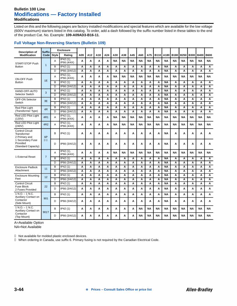
Bulletin 100 LineModifications — Factory Installed
3-44
3Modifications
Listed on this and the following pages are factory installed modifications and special features which are available for the low voltage(600V maximum) starters listed in this catalog. To order, add a dash followed by the suffix number listed in these tables to the endof the product Cat. No. Example: 109-A09AD3-B16-11 .
Full Voltage Non-Reversing Starters (Bulletin 109)
A=Available OptionNA=Not Available
➊ Not available for molded plastic enclosed devices.➋ When ordering in Canada, use suffix 6. Primary fusing is not required by the Canadian Electrical Code.
Description ofModification
Suffix Code
Enclosure
A09 A12 A18 A24 A30 A38 A45 A60 A75 B110 A180 B180 B250 B300 B400 B600Style Rating
START-STOP PushButton 1
A IP42 (1),IP66 (4/4X) A A A A NA NA NA NA NA NA NA NA NA NA NA NA
B IP42 (1) A A A A A A A A A A NA A A A A A
D IP66 (3/4/12) A A A A A A A A A A NA A A A A A
ON-OFF PushButton 1E
A IP42 (1),IP66 (4/4X) A A A A NA NA NA NA NA NA NA NA NA NA NA NA
B IP42 (1) A A A A A A A A A A NA A A A A A
D IP66 (3/4/12) A A A A A A A A A A NA A A A A A
HAND-OFF-AUTOSelector Switch 3
B IP42 (1) A A A A A A A A A A NA A A A A A
D IP66 (3/4/12) A A A A A A A A A A NA A A A A A
OFF-ON SelectorSwitch 3E
B IP42 (1) A A A A A A A A A A NA A A A A A
D IP66 (3/4/12) A A A A A A A A A A NA A A A A A
Red Pilot Light(Transformer Type) 4R
B IP42 (1) A A A A A A A A A A NA A A A A A
D IP66 (3/4/12) A A A A A A A A A A NA A A A A A
Red LED Pilot Light(120V) 4R1 A IP42 (1),
IP66 (4/4X) A A A A NA NA NA NA NA NA NA NA NA NA NA NA
Red LED Pilot Light(240V) 4R2 A IP42 (1),
IP66 (4/4X) A A A A NA NA NA NA NA NA NA NA NA NA NA NA
Control CircuitTransformer2 Primary and1 Secondary FuseProvided(Standard Capacity)
6P➊➋
B IP42 (1) A A A A A A A A A A NA A A A A A
D IP66 (3/4/12) A A A A A A A A A A NA A A A A A
1 External Reset 7
A IP42 (1),IP66 (4/4X) A A A A NA NA NA NA NA NA NA NA NA NA NA NA
B IP42 (1) A A A A A A A A A A NA A A A A A
D IP66 (3/4/12) A A A A A A A A A A NA A A A A A
Enclosure PadlockAttachment 11
B IP42 (1) A A A A A A A A A A NA A A A A A
D IP66 (3/4/12) A A A A A A A A A A NA A A A A A
Enclosure MountingFeet 12
B IP42 (1) A A A A A A A A A A NA A A A A A
D IP66 (3/4/12) A A A A A A A A A A NA A A A A A
Control CircuitFuse Block2 Fuses Provided
22B IP42 (1) A A A A A A A A A A NA A A A A A
D IP66 (3/4/12) A A A A A A A A A A NA A A A A A
1 N.O. – 1 N.C.Auxiliary Contact onContactor(Side Mount)
901
B IP42 (1) A A A A A A A A A A NA A A A A A
D IP66 (3/4/12) A A A A A A A A A A NA A A A A A
1 N.O. – 1 N.C.Auxiliary Contact onContactor(Top Mount)
901TB IP42 (1) A A A A A A A NA NA NA NA NA NA NA NA NA
D IP66 (3/4/12) A A A A A A A NA NA NA NA NA NA NA NA NA
Prices – Consult Sales Office or price list
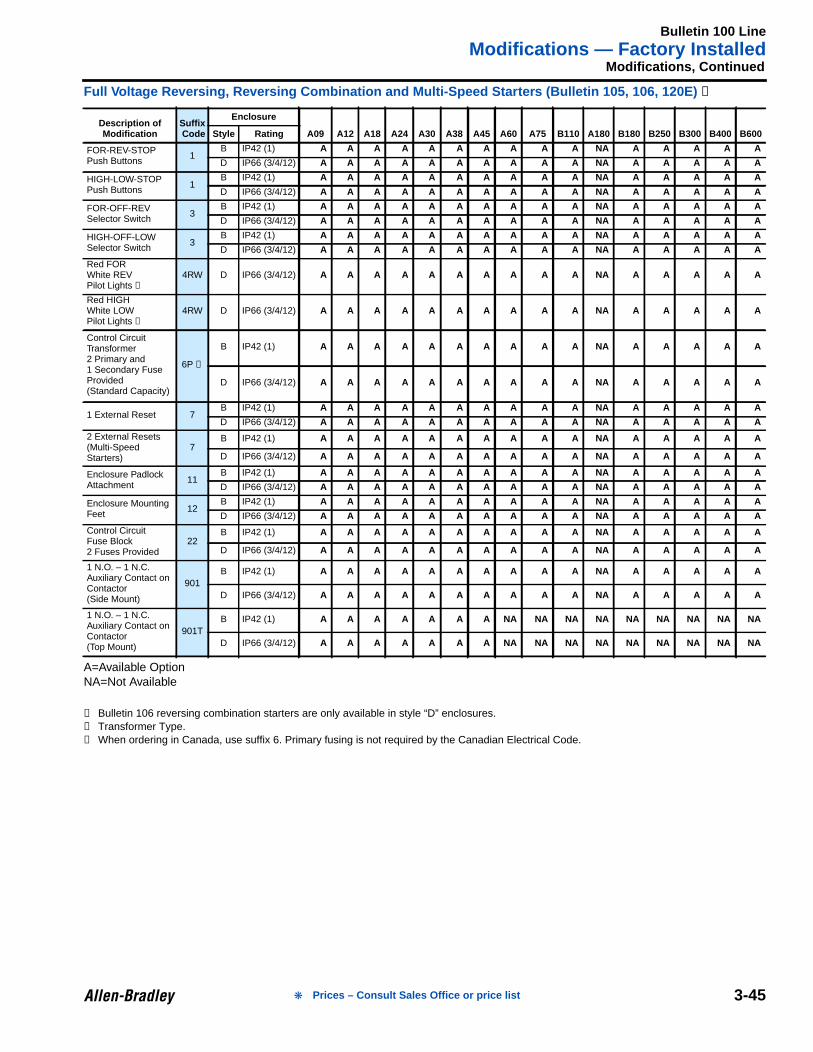
Bulletin 100 LineModifications — Factory Installed
3-45
Modifications, Continued
Full Voltage Reversing, Reversing Combination and Multi-Speed Starters (Bulletin 105, 106, 120E) ➊
A=Available OptionNA=Not Available
➊ Bulletin 106 reversing combination starters are only available in style “D” enclosures.➋ Transformer Type.➌ When ordering in Canada, use suffix 6. Primary fusing is not required by the Canadian Electrical Code.
Description ofModification
Suffix Code
Enclosure
A09 A12 A18 A24 A30 A38 A45 A60 A75 B110 A180 B180 B250 B300 B400 B600Style Rating
FOR-REV-STOPPush Buttons 1
B IP42 (1) A A A A A A A A A A NA A A A A A
D IP66 (3/4/12) A A A A A A A A A A NA A A A A A
HIGH-LOW-STOPPush Buttons 1
B IP42 (1) A A A A A A A A A A NA A A A A A
D IP66 (3/4/12) A A A A A A A A A A NA A A A A A
FOR-OFF-REVSelector Switch 3
B IP42 (1) A A A A A A A A A A NA A A A A A
D IP66 (3/4/12) A A A A A A A A A A NA A A A A A
HIGH-OFF-LOWSelector Switch 3
B IP42 (1) A A A A A A A A A A NA A A A A A
D IP66 (3/4/12) A A A A A A A A A A NA A A A A A
Red FORWhite REVPilot Lights ➋
4RW D IP66 (3/4/12) A A A A A A A A A A NA A A A A A
Red HIGHWhite LOWPilot Lights ➋
4RW D IP66 (3/4/12) A A A A A A A A A A NA A A A A A
Control CircuitTransformer2 Primary and1 Secondary FuseProvided(Standard Capacity)
6P ➌
B IP42 (1) A A A A A A A A A A NA A A A A A
D IP66 (3/4/12) A A A A A A A A A A NA A A A A A
1 External Reset 7B IP42 (1) A A A A A A A A A A NA A A A A A
D IP66 (3/4/12) A A A A A A A A A A NA A A A A A
2 External Resets(Multi-SpeedStarters)
7B IP42 (1) A A A A A A A A A A NA A A A A A
D IP66 (3/4/12) A A A A A A A A A A NA A A A A A
Enclosure PadlockAttachment 11
B IP42 (1) A A A A A A A A A A NA A A A A A
D IP66 (3/4/12) A A A A A A A A A A NA A A A A A
Enclosure MountingFeet 12
B IP42 (1) A A A A A A A A A A NA A A A A A
D IP66 (3/4/12) A A A A A A A A A A NA A A A A A
Control CircuitFuse Block2 Fuses Provided
22B IP42 (1) A A A A A A A A A A NA A A A A A
D IP66 (3/4/12) A A A A A A A A A A NA A A A A A
1 N.O. – 1 N.C.Auxiliary Contact onContactor(Side Mount)
901B IP42 (1) A A A A A A A A A A NA A A A A A
D IP66 (3/4/12) A A A A A A A A A A NA A A A A A
1 N.O. – 1 N.C.Auxiliary Contact onContactor(Top Mount)
901TB IP42 (1) A A A A A A A NA NA NA NA NA NA NA NA NA
D IP66 (3/4/12) A A A A A A A NA NA NA NA NA NA NA NA NA
Prices – Consult Sales Office or price list
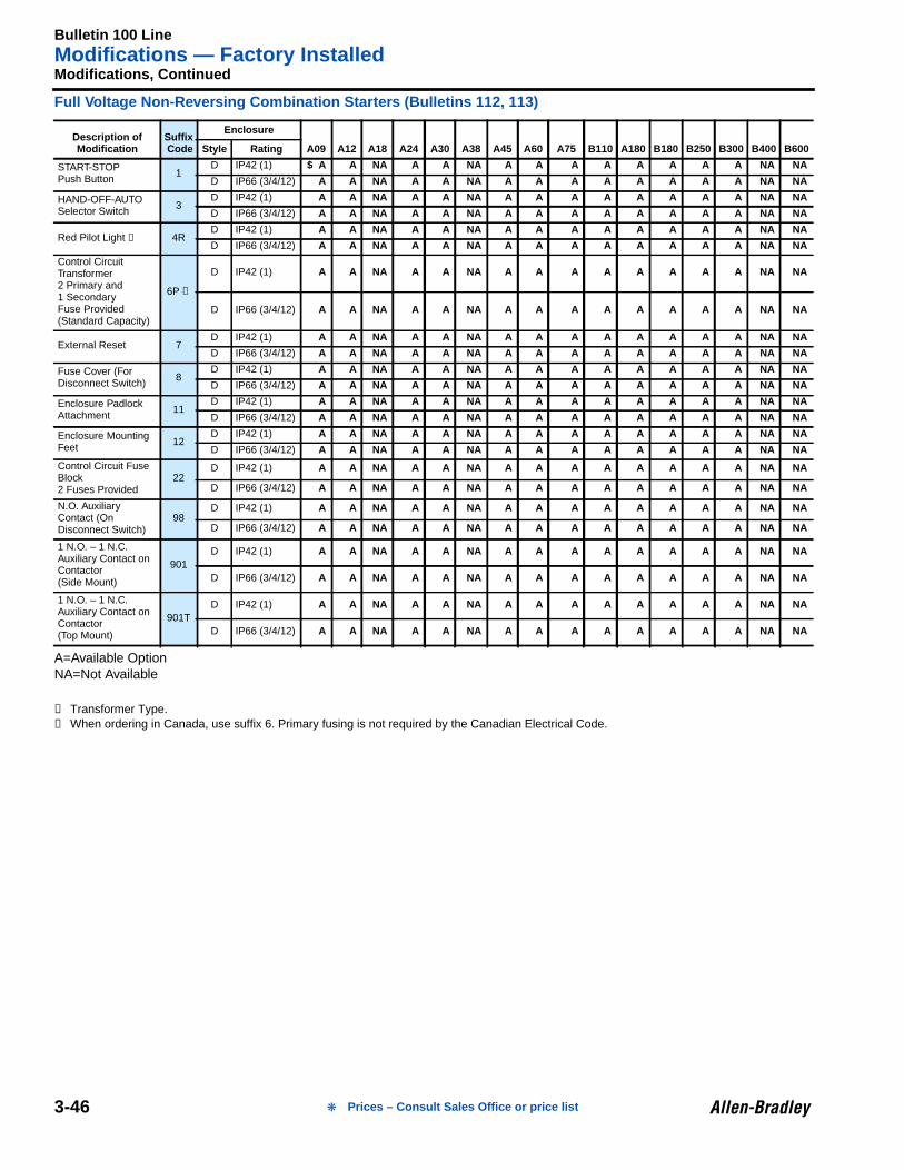
Bulletin 100 LineModifications — Factory Installed
3-46
Modifications, Continued
Full Voltage Non-Reversing Combination Starters (Bulletins 112, 113)
A=Available OptionNA=Not Available
➊ Transformer Type.➋ When ordering in Canada, use suffix 6. Primary fusing is not required by the Canadian Electrical Code.
Description ofModification
Suffix Code
Enclosure
A09 A12 A18 A24 A30 A38 A45 A60 A75 B110 A180 B180 B250 B300 B400 B600Style Rating
START-STOPPush Button 1
D IP42 (1) $ A A NA A A NA A A A A A A A A NA NA
D IP66 (3/4/12) A A NA A A NA A A A A A A A A NA NA
HAND-OFF-AUTOSelector Switch 3
D IP42 (1) A A NA A A NA A A A A A A A A NA NA
D IP66 (3/4/12) A A NA A A NA A A A A A A A A NA NA
Red Pilot Light ➊ 4RD IP42 (1) A A NA A A NA A A A A A A A A NA NA
D IP66 (3/4/12) A A NA A A NA A A A A A A A A NA NA
Control CircuitTransformer2 Primary and1 SecondaryFuse Provided(Standard Capacity)
6P ➋
D IP42 (1) A A NA A A NA A A A A A A A A NA NA
D IP66 (3/4/12) A A NA A A NA A A A A A A A A NA NA
External Reset 7D IP42 (1) A A NA A A NA A A A A A A A A NA NA
D IP66 (3/4/12) A A NA A A NA A A A A A A A A NA NA
Fuse Cover (ForDisconnect Switch) 8
D IP42 (1) A A NA A A NA A A A A A A A A NA NA
D IP66 (3/4/12) A A NA A A NA A A A A A A A A NA NA
Enclosure PadlockAttachment 11
D IP42 (1) A A NA A A NA A A A A A A A A NA NA
D IP66 (3/4/12) A A NA A A NA A A A A A A A A NA NA
Enclosure MountingFeet 12
D IP42 (1) A A NA A A NA A A A A A A A A NA NA
D IP66 (3/4/12) A A NA A A NA A A A A A A A A NA NA
Control Circuit FuseBlock2 Fuses Provided
22D IP42 (1) A A NA A A NA A A A A A A A A NA NA
D IP66 (3/4/12) A A NA A A NA A A A A A A A A NA NA
N.O. AuxiliaryContact (OnDisconnect Switch)
98D IP42 (1) A A NA A A NA A A A A A A A A NA NA
D IP66 (3/4/12) A A NA A A NA A A A A A A A A NA NA
1 N.O. – 1 N.C.Auxiliary Contact onContactor(Side Mount)
901D IP42 (1) A A NA A A NA A A A A A A A A NA NA
D IP66 (3/4/12) A A NA A A NA A A A A A A A A NA NA
1 N.O. – 1 N.C.Auxiliary Contact onContactor(Top Mount)
901TD IP42 (1) A A NA A A NA A A A A A A A A NA NA
D IP66 (3/4/12) A A NA A A NA A A A A A A A A NA NA
Prices – Consult Sales Office or price list
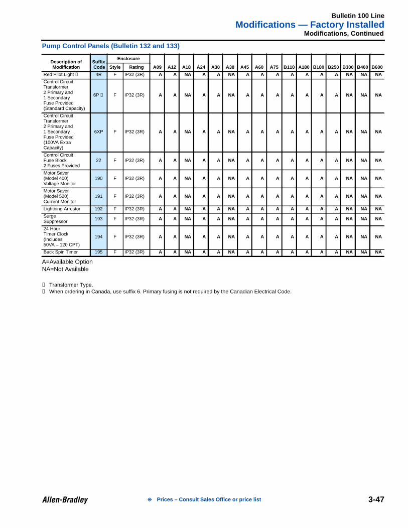
Bulletin 100 LineModifications — Factory Installed
3-47
Modifications, Continued
Pump Control Panels (Bulletin 132 and 133)
A=Available OptionNA=Not Available
➊ Transformer Type.➋ When ordering in Canada, use suffix 6. Primary fusing is not required by the Canadian Electrical Code.
Description ofModification
Suffix Code
Enclosure
A09 A12 A18 A24 A30 A38 A45 A60 A75 B110 A180 B180 B250 B300 B400 B600Style Rating
Red Pilot Light ➊ 4R F IP32 (3R) A A NA A A NA A A A A A A A NA NA NA
Control CircuitTransformer2 Primary and1 SecondaryFuse Provided(Standard Capacity)
6P ➋ F IP32 (3R) A A NA A A NA A A A A A A A NA NA NA
Control CircuitTransformer2 Primary and1 SecondaryFuse Provided(100VA ExtraCapacity)
6XP F IP32 (3R) A A NA A A NA A A A A A A A NA NA NA
Control CircuitFuse Block2 Fuses Provided
22 F IP32 (3R) A A NA A A NA A A A A A A A NA NA NA
Motor Saver(Model 400)Voltage Monitor
190 F IP32 (3R) A A NA A A NA A A A A A A A NA NA NA
Motor Saver(Model 520)Current Monitor
191 F IP32 (3R) A A NA A A NA A A A A A A A NA NA NA
Lightning Arrestor 192 F IP32 (3R) A A NA A A NA A A A A A A A NA NA NA
SurgeSuppressor 193 F IP32 (3R) A A NA A A NA A A A A A A A NA NA NA
24 HourTimer Clock(Includes50VA – 120 CPT)
194 F IP32 (3R) A A NA A A NA A A A A A A A NA NA NA
Back Spin Timer 195 F IP32 (3R) A A NA A A NA A A A A A A A NA NA NA
Prices – Consult Sales Office or price list
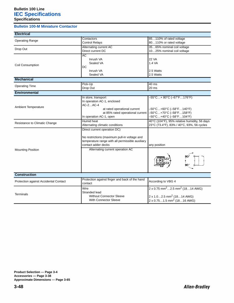
Bulletin 100 LineIEC Specifications
3-48
3Specifications
Bulletin 100-M Miniature Contactor
Electrical
Operating RangeContactorsControl Relays
85…110% of rated voltage80…110% or rated voltage
Drop OutAlternating current ACDirect current DC
35…65% nominal coil voltage10…25% nominal coil voltage
Coil Consumption
ACInrush VASealed VA
DCInrush VASealed VA
22 VA1.4 VA
2.5 Watts2.5 Watts
Mechanical
Operating TimePick-UpDrop Out
40 ms20 ms
Environmental
Ambient Temperature
In store, transportIn operation AC-1, enclosedAC-2…AC-4
at rated operational currentat 85% rated operational current
In operation AC-1, open
–55°C…+ 80°C (–67°F…176°F)
–50°C…+60°C (–58°F…140°F)–50°C…+70°C (–58°F…158°F)–50°C…+40°C (–58°F…104°F)
Resistance to Climatic ChangeHumid heatAlternating climatic conditions
40°C (104°F), 95% relative humidity, 56 days23°C (73.4°F), 83% / 40°C, 93%, 56 cycles
Mounting Position
Direct current operation DC)
No restrictions (maximum pull-in voltage andtemperature range with all permissible auxiliarycontact adder decks any position
Alternating current operation AC
Construction
Protection against Accidental ContactProtection against finger and back of the handcontact
According to VBG 4
Terminals
WireStranded lead
Without Connector SleeveWith Connector Sleeve
2 x 0.75 mm2…2.5 mm2 (18…14 AWG)
2 x 1.0…2.5 mm2 (18…14 AWG)2 x 0.75…1.5 mm2 (18…16 AWG)
Product Selection — Page 3-4Accessories — Page 3-38Approximate Dimensions — Page 3-65
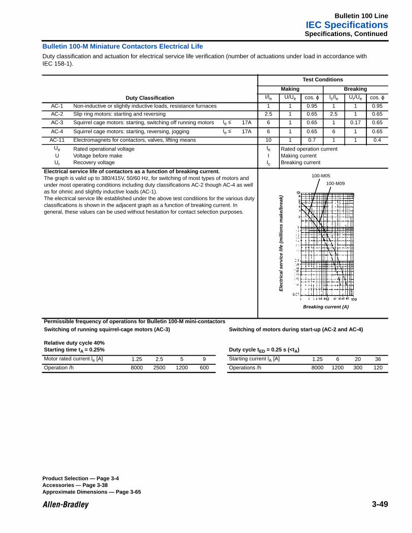
Bulletin 100 LineIEC Specifications
3-49
Specifications, Continued
Bulletin 100-M Miniature Contactors Electrical LifeDuty classification and actuation for electrical service life verification (number of actuations under load in accordance withIEC 158-1).
Duty Classification
Test Conditions
Making BreakingI/Ie U/Ue cos. ϕ Ic/Ie Ur/Ue cos. ϕ
AC-1 Non-inductive or slightly inductive loads, resistance furnaces 1 1 0.95 1 1 0.95
AC-2 Slip ring motors: starting and reversing 2.5 1 0.65 2.5 1 0.65
AC-3 Squirrel cage motors: starting, switching off running motors Ie ≤ 17A 6 1 0.65 1 0.17 0.65
AC-4 Squirrel cage motors: starting, reversing, jogging Ie ≤ 17A 6 1 0.65 6 1 0.65
AC-11 Electromagnets for contactors, valves, lifting means 10 1 0.7 1 1 0.4
Ue
UUr
Rated operational voltageVoltage before makeRecovery voltage
IeIIc
Rated operation currentMaking currentBreaking current
Electrical service life of contactors as a function of breaking current.The graph is valid up to 380/415V, 50/60 Hz, for switching of most types of motors andunder most operating conditions including duty classifications AC-2 though AC-4 as wellas for ohmic and slightly inductive loads (AC-1).The electrical service life established under the above test conditions for the various dutyclassifications is shown in the adjacent graph as a function of breaking current. Ingeneral, these values can be used without hesitation for contact selection purposes.
Permissible frequency of operations for Bulletin 100-M mini-contactorsSwitching of running squirrel-cage motors (AC-3)
Relative duty cycle 40%Starting time t A = 0.25%
Switching of motors during start-up (AC-2 and AC-4)
Duty cycle t ED = 0.25 s (<tA)
Motor rated current le [A] 1.25 2.5 5 9 Starting current lA [A] 1.25 6 20 36
Operation /h 8000 2500 1200 600 Operations /h 8000 1200 300 120
Ele
ctric
al s
ervi
ce li
fe (
mill
ions
mak
e/br
eak)
Breaking current (A)
100-M05
100-M09
Product Selection — Page 3-4Accessories — Page 3-38Approximate Dimensions — Page 3-65
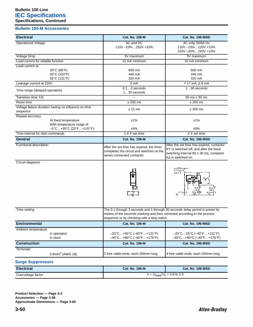
Bulletin 100 LineIEC Specifications
3-50
Specifications, Continued
Bulletin 100-M Accessories
Surge Suppressors
Electrical Cat. No. 196-M Cat. No. 196-MSD
Operational Voltage AC and DC110V –23%…250V +10%
AC only, 50/60 Hz110V –23%…120V +10%220V –20%…240V +10%
Voltage Drop 5V maximum 5V maximum
Load current for reliable function 10 mA minimum 10 mA minimum
Load current at20°C (68°F)40°C (104°F)55°C (131°F)
600 mA440 mA320 mA
600 mA440 mA320 mA
Leakage current at 220V 5 mA Y 17 mA, ∆ 6 mA
Time range (delayed operation)0.1…3 seconds1…30 seconds
1…30 seconds
Transition time Y/∆ – 90 ms ± 30 ms
Reset time ≥ 200 ms ≥ 200 ms
Voltage failure duration having no influence on timesequence
≤ 15 ms ≥ 200 ms
Repeat accuracyAt fixed temperatureWith temperature range of–5°C…+55°C (23°F…+131°F)
±1%
±5%
±1%
±5%
Time interval for start commands 1.4 X set time 2 X set time
General Cat. No. 196-M Cat. No. 196-MSD
Functional descriptionAfter the set time has expired, the timercompletes the circuit and switches on theseries connected contactor.
After the set time has expired, contactorKY is switched off, and after the fixedswitching interval 90 ± 30 ms, contactorK∆ is switched on.
Circuit diagrams
Time setting The 0.1 through 3 seconds and 1 through 30 seconds delay period is preset bymeans of the seconds marking and then corrected according to the processsequence or by checking with a stop watch.
Environmental Cat. No. 196-M Cat. No. 196-MSD
Ambient temperaturein operationin store
–20°C…+55°C (–40°F…+131°F)–40°C…+80°C (–40°F…+176°F)
–20°C…55°C (–40°F…+131°F)–40°C…+80°C (–40°F…+176°F)
Construction Cat. No. 196-M Cat. No. 196-MSD
Terminals:
0.8mm2 (AWG 18) 2 free cable ends, each 250mm long 4 free cable ends, each 250mm long
Electrical Cat. No. 196-M Cat. No. 196-MSD
Overvoltage factor n = Umax/Un = 0.8 to 2.5
Product Selection — Page 3-4Accessories — Page 3-38Approximate Dimensions — Page 3-65
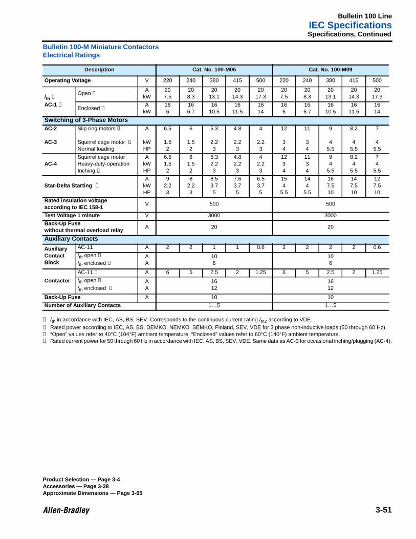
Bulletin 100 LineIEC Specifications
3-51
Specifications, Continued
Bulletin 100-M Miniature ContactorsElectrical Ratings
➊ /th in accordance with IEC, AS, BS, SEV. Corresponds to the continuous current rating /th2 according to VDE.➋ Rated power according to IEC, AS, BS, DEMKO, NEMKO, SEMKO, Finland, SEV, VDE for 3 phase non-inductive loads (50 through 60 Hz).➌ “Open” values refer to 40°C (104°F) ambient temperature. “Enclosed” values refer to 60°C (140°F) ambient temperature.➍ Rated current power for 50 through 60 Hz in accordance with IEC, AS, BS, SEV, VDE. Same data as AC-3 for occasional inching/plugging (AC-4).3
Description Cat. No. 100-M05 Cat. No. 100-M09
Operating Voltage V 220 240 380 415 500 220 240 380 415 500
/th ➊
AC-1 ➋
Open ➌A
kW207.5
208.3
2013.1
2014.3
2017.3
207.5
208.3
2013.1
2014.3
2017.3
Enclosed ➌A
kW166
166.7
1610.5
1611.5
1614
166
166.7
1610.5
1611.5
1614
Switching of 3-Phase MotorsAC-2
AC-3
Slip ring motors ➍
Squirrel cage motor ➍
Normal loading
A
kWHP
6.5
1.52
6
1.52
5.3
2.23
4.8
2.23
4
2.23
12
34
11
34
9
45.5
8.2
45.5
7
45.5
AC-4Squirrel cage motorHeavy-duty-operationInching ➍
AkWHP
6.51.52
61.52
5.32.23
4.82.23
42.23
1234
1134
94
5.5
8.24
5.5
74
5.5
Star-Delta Starting ➍
AkWHP
92.23
82.23
8.53.75
7.63.75
6.53.75
154
5.5
144
5.5
167.510
147.510
127.510
Rated insulation voltageaccording to IEC 158-1
V 500 500
Test Voltage 1 minute V 3000 3000
Back-Up Fusewithout thermal overload relay
A 20 20
Auxiliary Contacts
AuxiliaryContactBlock
AC-11 A 2 2 1 1 0.6 2 2 2 2 0.6
/th open ➌
/th enclosed ➌
AA
106
106
Contactor
AC-11 ➊ A 6 5 2.5 2 1.25 6 5 2.5 2 1.25
/th open ➌
/th enclosed ➌
AA
1612
1612
Back-Up Fuse A 10 10
Number of Auxiliary Contacts 1…5 1…5
Product Selection — Page 3-4Accessories — Page 3-38Approximate Dimensions — Page 3-65
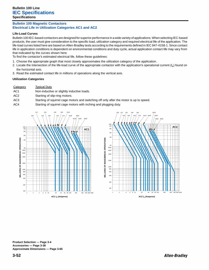
Bulletin 100 LineIEC Specifications
3-52
Specifications
Bulletin 100 Magnetic ContactorsElectrical Life in Utilization Categories AC1 and AC2
Life-Load CurvesBulletin 100 IEC-based contactors are designed for superior performance in a wide variety of applications. When selecting IEC-basedproducts, the user must give consideration to the specific load, utilization category and required electrical life of the application. Thelife-load curves listed here are based on Allen-Bradley tests according to the requirements defined in IEC 947-4158-1. Since contactlife in application conditions is dependent on environmental conditions and duty cycle, actual application contact life may vary fromthat indicated by the curves shown here.To find the contactor’s estimated electrical life, follow these guidelines:
1. Choose the appropriate graph that most closely approximates the utilization category of the application.2. Locate the intersection of the life-load curve of the appropriate contactor with the application’s operational current (le) found on
the horizontal axis.3. Read the estimated contact life in millions of operations along the vertical axis.
Utilization Categories
Category Typical DutyAC1 Non-inductive or slightly inductive loads.AC2 Starting of slip-ring motors.AC3 Starting of squirrel cage motors and switching off only after the motor is up to speed.AC4 Starting of squirrel cage motors with inching and plugging duty.
A09 A12
A18
A24
A30
A38
A45
A60
A75 B110 B180
B250
B300
B400 B600
10M8M
6M
4M
2M
1M
800K
600K
400K
200K
100K
80K
60K
40K
20K
10K
1 2 4 6 8 10 20 40 60 80 100 200 400 600 800 1000
AC2
AC2 le (Amperes)
A09
A12
A18
A24
A30
A38
A45
A60
A75
B110
B180
B250
B300
B400 B600
10M8M
6M
4M
2M
1M
800K
600K
400K
200K
100K
80K
60K
40K
20K
10K
1 2 4 6 8 10 20 40 60 80 100 200 400 600 800 1000
AC1
AC1 le (Amperes)
MIL
LIO
NS
OF
MA
KE
/BR
EA
K O
PE
RA
TIO
NS
MIL
LIO
NS
OF
MA
KE
/BR
EA
K O
PE
RA
TIO
NS
Product Selection — Page 3-4Accessories — Page 3-38Approximate Dimensions — Page 3-65
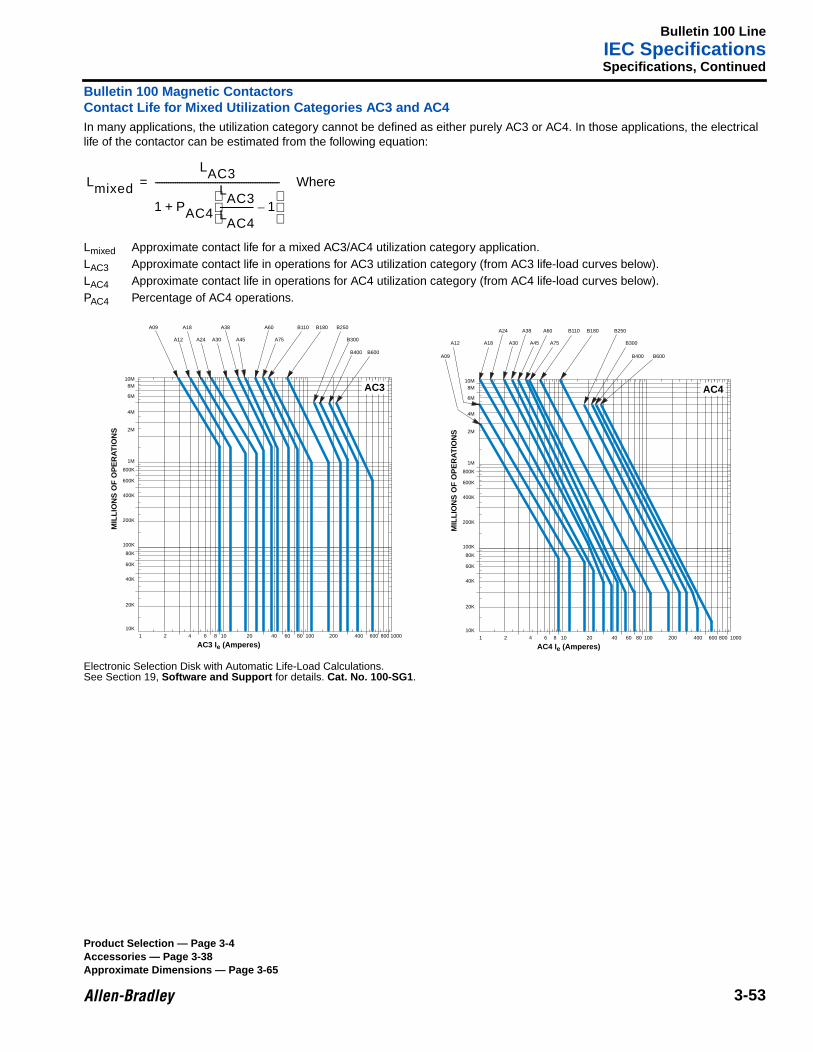
Bulletin 100 LineIEC Specifications
3-53
Specifications, Continued
Bulletin 100 Magnetic ContactorsContact Life for Mixed Utilization Categories AC3 and AC4In many applications, the utilization category cannot be defined as either purely AC3 or AC4. In those applications, the electricallife of the contactor can be estimated from the following equation:
Lmixed Approximate contact life for a mixed AC3/AC4 utilization category application.LAC3 Approximate contact life in operations for AC3 utilization category (from AC3 life-load curves below).LAC4 Approximate contact life in operations for AC4 utilization category (from AC4 life-load curves below).PAC4 Percentage of AC4 operations.
Electronic Selection Disk with Automatic Life-Load Calculations.See Section 19, Software and Support for details. Cat. No. 100-SG1 .
Lmixed
LAC3
1 PAC4AC3
L
AC4L--------------- 1–
+
-------------------------------------------------------- Where=
A09
A12
A18
A24 A30
A38
A45
A60
A75
B110 B180 B250
B300
B400 B600
10M8M
6M
4M
2M
1M
800K
600K
400K
200K
100K
80K
60K
40K
20K
10K
1 2 4 6 8 10 20 40 60 80 100 200 400 600 800 1000
AC3
AC3 Ie (Amperes)
MIL
LIO
NS
OF
OP
ER
AT
ION
S
A09
A12 A18
A24
A30
A38
A45
A60
A75
B110 B180 B250
B300
B400 B600
10M8M
6M
4M
2M
1M
800K
600K
400K
200K
100K
80K
60K
40K
20K
10K
1 2 4 6 8 10 20 40 60 80 100 200 400 600 800 1000
AC4
AC4 Ie (Amperes)
MIL
LIO
NS
OF
OP
ER
AT
ION
S
Product Selection — Page 3-4Accessories — Page 3-38Approximate Dimensions — Page 3-65
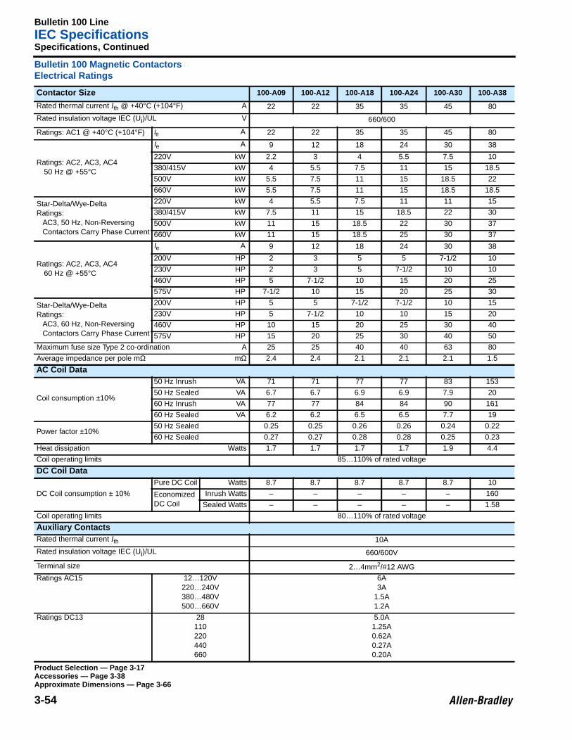
Bulletin 100 LineIEC Specifications
3-54
Specifications, Continued
Bulletin 100 Magnetic ContactorsElectrical Ratings
Contactor Size 100-A09 100-A12 100-A18 100-A24 100-A30 100-A38
Rated thermal current Ith @ +40°C (+104°F) A 22 22 35 35 45 80
Rated insulation voltage IEC (Ui)/UL V 660/600
Ratings: AC1 @ +40°C (+104°F) ie A 22 22 35 35 45 80
Ratings: AC2, AC3, AC450 Hz @ +55°C
Ie A 9 12 18 24 30 38
220V kW 2.2 3 4 5.5 7.5 10
380/415V kW 4 5.5 7.5 11 15 18.5
500V kW 5.5 7.5 11 15 18.5 22
660V kW 5.5 7.5 11 15 18.5 18.5
Star-Delta/Wye-DeltaRatings:
AC3, 50 Hz, Non-ReversingContactors Carry Phase Current
220V kW 4 5.5 7.5 11 11 15
380/415V kW 7.5 11 15 18.5 22 30
500V kW 11 15 18.5 22 30 37
660V kW 11 15 18.5 25 30 37
Ratings: AC2, AC3, AC460 Hz @ +55°C
Ie A 9 12 18 24 30 38
200V HP 2 3 5 5 7-1/2 10
230V HP 2 3 5 7-1/2 10 10
460V HP 5 7-1/2 10 15 20 25
575V HP 7-1/2 10 15 20 25 30
Star-Delta/Wye-DeltaRatings:
AC3, 60 Hz, Non-ReversingContactors Carry Phase Current
200V HP 5 5 7-1/2 7-1/2 10 15
230V HP 5 7-1/2 10 10 15 20
460V HP 10 15 20 25 30 40
575V HP 15 20 25 30 40 50
Maximum fuse size Type 2 co-ordination A 25 25 40 40 63 80
Average impedance per pole mΩ mΩ 2.4 2.4 2.1 2.1 2.1 1.5
AC Coil Data
Coil consumption ±10%
50 Hz Inrush VA 71 71 77 77 83 153
50 Hz Sealed VA 6.7 6.7 6.9 6.9 7.9 20
60 Hz Inrush VA 77 77 84 84 90 161
60 Hz Sealed VA 6.2 6.2 6.5 6.5 7.7 19
Power factor ±10%50 Hz Sealed 0.25 0.25 0.26 0.26 0.24 0.22
60 Hz Sealed 0.27 0.27 0.28 0.28 0.25 0.23
Heat dissipation Watts 1.7 1.7 1.7 1.7 1.9 4.4
Coil operating limits 85…110% of rated voltage
DC Coil Data
DC Coil consumption ± 10%
Pure DC Coil Watts 8.7 8.7 8.7 8.7 8.7 10
EconomizedDC Coil
Inrush Watts – – – – – 160
Sealed Watts – – – – – 1.58
Coil operating limits 80…110% of rated voltage
Auxiliary ContactsRated thermal current Ith 10A
Rated insulation voltage IEC (Ui)/UL 660/600V
Terminal size 2…4mm2/#12 AWG
Ratings AC15 12…120V220…240V380…480V500…660V
6A3A
1.5A1.2A
Ratings DC13 28110220440660
5.0A1.25A0.62A0.27A0.20A
Product Selection — Page 3-17Accessories — Page 3-38Approximate Dimensions — Page 3-66
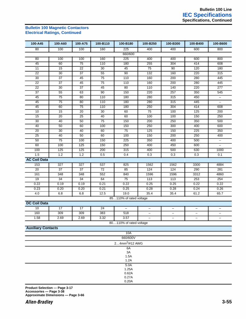
Bulletin 100 LineIEC Specifications
3-55
Specifications, Continued
Bulletin 100 Magnetic ContactorsElectrical Ratings, Continued
100-A45 100-A60 100-A75 100-B110 100-B180 100-B250 100-B300 100-B400 100-B600
80 100 100 160 225 400 400 600 800
660/600
80 100 100 160 225 400 400 600 800
45 60 75 110 180 255 304 414 608
11 15 22 30 45 75 90 120 180
22 30 37 55 90 132 160 220 315
30 37 45 75 110 160 200 280 445
22 37 45 75 110 160 200 280 445
22 30 37 45 80 110 140 220 277
37 55 63 90 150 220 257 350 545
45 75 80 110 180 280 315 450 –
45 75 80 110 180 280 315 445 –
45 60 75 110 180 250 304 414 608
10 15 20 30 60 75 100 125 200
15 20 25 40 60 100 100 150 250
30 40 50 75 150 200 250 350 500
40 50 60 100 150 250 300 400 600
20 30 40 60 75 125 150 225 350
25 40 50 60 100 150 200 250 400
50 75 100 150 225 350 400 500 –
60 100 125 150 250 400 450 600 –
100 125 125 200 315 400 500 630 1000
1.5 1.2 1.2 0.5 0.4 0.3 0.3 0.3 0.1
AC Coil Data153 327 327 537 825 1562 1562 3300 4884
20 37 37 72 85 124 124 290 281
161 348 348 552 840 1596 1596 3312 4860
19 34 34 64 75 113 113 253 254
0.22 0.19 0.19 0.21 0.22 0.25 0.25 0.22 0.22
0.23 0.20 0.20 0.21 0.25 0.28 0.28 0.24 0.26
4.0 6.8 6.8 12.5 19.0 35.4 35.4 61.2 65.7
85…110% of rated voltage
DC Coil Data10 17 17 24 – – – – –
160 309 309 383 518 – – – –
1.58 2.69 2.69 3.32 3.57 – – – –
80…110% of rated voltage
Auxiliary Contacts10A
660/600V
2…4mm2/#12 AWG
6A3A
1.5A1.2A
5.0A1.25A0.62A0.27A0.20A
Product Selection — Page 3-17Accessories — Page 3-38Approximate Dimensions — Page 3-66
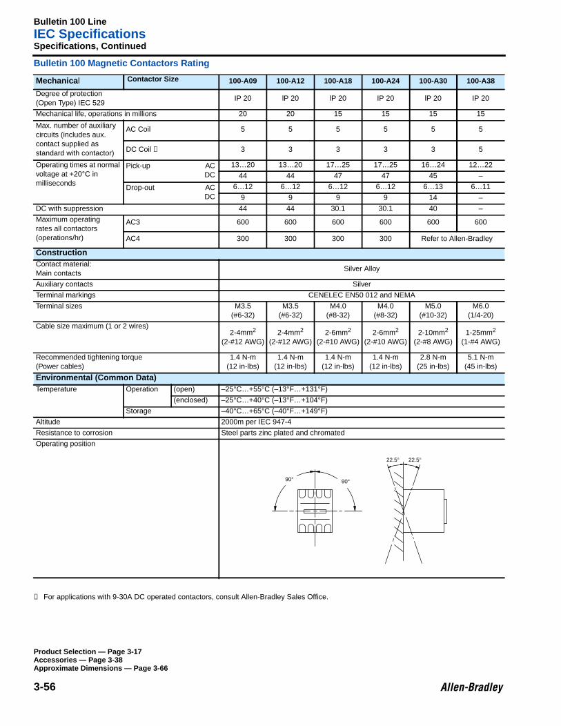
Bulletin 100 LineIEC Specifications
3-56
Specifications, Continued
Bulletin 100 Magnetic Contactors Rating
➊ For applications with 9-30A DC operated contactors, consult Allen-Bradley Sales Office.
Mechanica l Contactor Size 100-A09 100-A12 100-A18 100-A24 100-A30 100-A38
Degree of protection(Open Type) IEC 529
IP 20 lP 20 lP 20 IP 20 lP 20 IP 20
Mechanical life, operations in millions 20 20 15 15 15 15
Max. number of auxiliarycircuits (includes aux.contact supplied asstandard with contactor)
AC Coil 5 5 5 5 5 5
DC Coil ➊ 3 3 3 3 3 5
Operating times at normalvoltage at +20°C inmilliseconds
Pick-up ACDC
13…20 13…20 17…25 17…25 16…24 12…22
44 44 47 47 45 –
Drop-out ACDC
6…12 6…12 6…12 6…12 6…13 6…11
9 9 9 9 14 –
DC with suppression 44 44 30.1 30.1 40 –
Maximum operatingrates all contactors(operations/hr)
AC3 600 600 600 600 600 600
AC4 300 300 300 300 Refer to Allen-Bradley
ConstructionContact material:Main contacts
Silver Alloy
Auxiliary contacts Silver
Terminal markings CENELEC EN50 012 and NEMA
Terminal sizes M3.5(#6-32)
M3.5(#6-32)
M4.0(#8-32)
M4.0(#8-32)
M5.0(#10-32)
M6.0(1/4-20)
Cable size maximum (1 or 2 wires)2-4mm2
(2-#12 AWG)2-4mm2
(2-#12 AWG)2-6mm2
(2-#10 AWG)2-6mm2
(2-#10 AWG)2-10mm2
(2-#8 AWG)1-25mm2
(1-#4 AWG)
Recommended tightening torque(Power cables)
1.4 N-m(12 in-lbs)
1.4 N-m(12 in-lbs)
1.4 N-m(12 in-lbs)
1.4 N-m(12 in-lbs)
2.8 N-m(25 in-lbs)
5.1 N-m(45 in-lbs)
Environmental (Common Data)Temperature Operation (open) –25°C…+55°C (–13°F…+131°F)
(enclosed) –25°C…+40°C (–13°F…+104°F)
Storage –40°C…+65°C (–40°F…+149°F)
Altitude 2000m per IEC 947-4
Resistance to corrosion Steel parts zinc plated and chromated
Operating position
90° 90°
22.5°22.5°
Product Selection — Page 3-17Accessories — Page 3-38Approximate Dimensions — Page 3-66
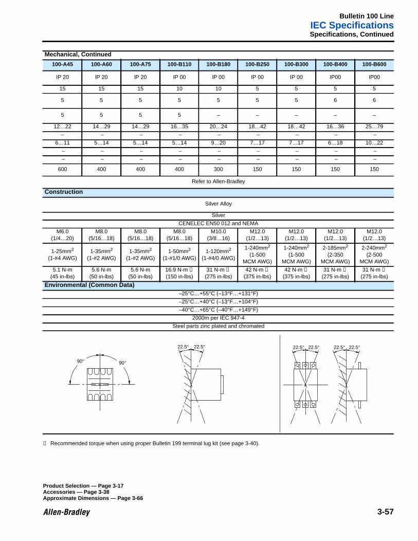
Bulletin 100 LineIEC Specifications
3-57
Specifications, Continued
➊ Recommended torque when using proper Bulletin 199 terminal lug kit (see page 3-40).
Mechanical, Continued
100-A45 100-A60 100-A75 100-B110 100-B180 100-B250 100-B300 100-B400 100-B600
IP 20 lP 20 lP 20 IP 00 lP 00 IP 00 IP 00 IP00 IP00
15 15 15 10 10 5 5 5 5
5 5 5 5 5 5 5 6 6
5 5 5 5 – – – – –
12…22 14…29 14…29 16…35 20…24 18…42 18…42 16…36 25…79
– – – – – – – – –
6…11 5…14 5…14 5…14 9…20 7…17 7…17 6…18 10…22
– – – – – – – – –
– – – – – – – – –
600 400 400 400 300 150 150 150 150
Refer to Allen-Bradley
Construction
Silver Alloy
Silver
CENELEC EN50 012 and NEMA
M6.0(1/4…20)
M8.0(5/16…18)
M8.0(5/16…18)
M8.0(5/16…18)
M10.0(3/8…16)
M12.0(1/2…13)
M12.0(1/2…13)
M12.0(1/2…13)
M12.0(1/2…13)
1-25mm2
(1-#4 AWG)1-35mm2
(1-#2 AWG)1-35mm2
(1-#2 AWG)1-50mm2
(1-#1/0 AWG)1-120mm2
(1-#4/0 AWG)
1-240mm2
(1-500MCM AWG)
1-240mm2
(1-500MCM AWG)
2-185mm2
(2-350MCM AWG)
2-240mm2
(2-500MCM AWG)
5.1 N-m(45 in-lbs)
5.6 N-m(50 in-lbs)
5.6 N-m(50 in-lbs)
16.9 N-m ➊
(150 in-lbs)31 N-m ➊
(275 in-lbs)42 N-m ➊
(375 in-lbs)42 N-m ➊
(375 in-lbs)31 N-m ➊
(275 in-lbs)31 N-m ➊
(275 in-lbs)
Environmental (Common Data)–25°C…+55°C (–13°F…+131°F)
–25°C…+40°C (–13°F…+104°F)
–40°C…+65°C (–40°F…+149°F)
2000m per IEC 947-4
Steel parts zinc plated and chromated
90°
22.5°
90°
22.5°22.5° 22.5°22.5° 22.5°
Product Selection — Page 3-17Accessories — Page 3-38Approximate Dimensions — Page 3-66
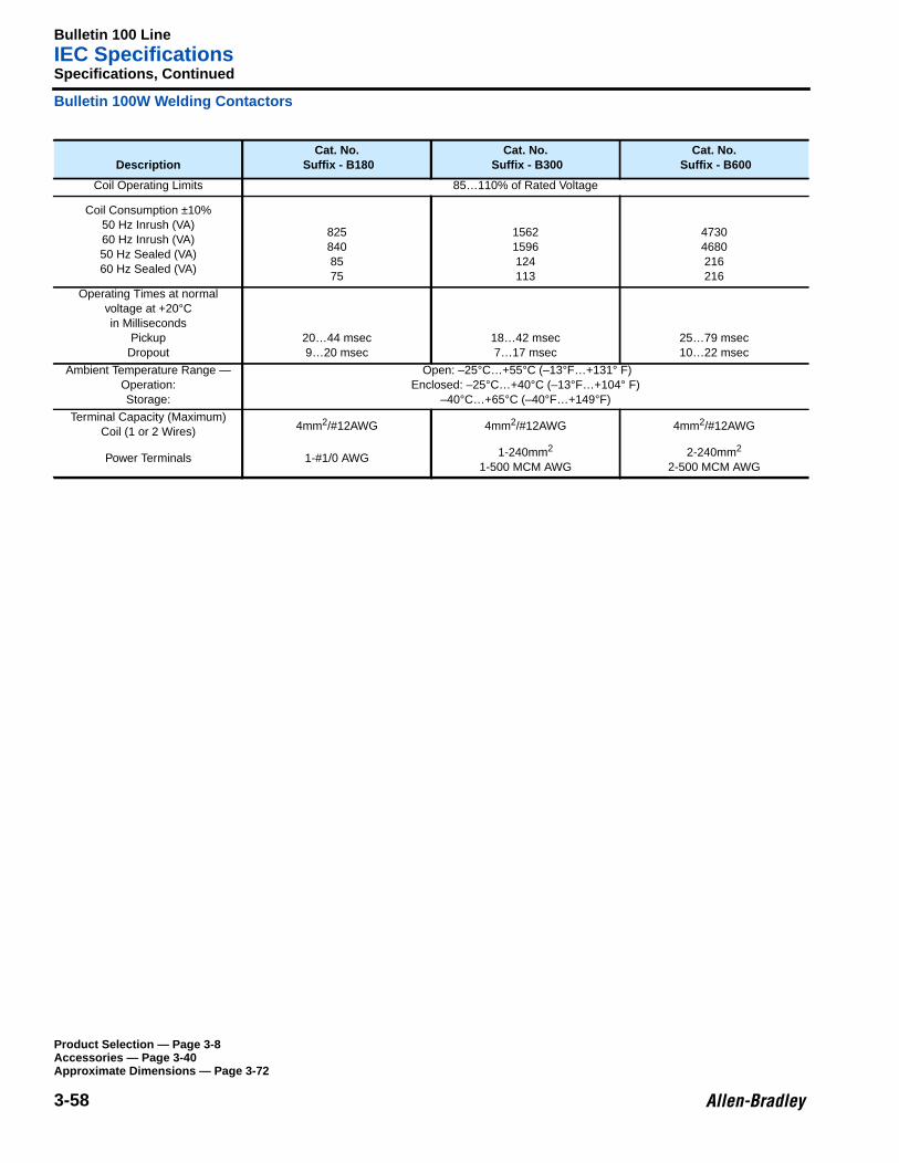
Bulletin 100 LineIEC Specifications
3-58
Specifications, Continued
Bulletin 100W Welding Contactors
DescriptionCat. No.
Suffix - B180Cat. No.
Suffix - B300Cat. No.
Suffix - B600
Coil Operating Limits 85…110% of Rated Voltage
Coil Consumption ±10%50 Hz Inrush (VA)60 Hz Inrush (VA)50 Hz Sealed (VA)60 Hz Sealed (VA)
8258408575
15621596124113
47304680216216
Operating Times at normalvoltage at +20°Cin Milliseconds
PickupDropout
20…44 msec9…20 msec
18…42 msec7…17 msec
25…79 msec10…22 msec
Ambient Temperature Range —Operation:Storage:
Open: –25°C…+55°C (–13°F…+131° F)Enclosed: –25°C…+40°C (–13°F…+104° F)
–40°C…+65°C (–40°F…+149°F)
Terminal Capacity (Maximum)Coil (1 or 2 Wires) 4mm2/#12AWG 4mm2/#12AWG 4mm2/#12AWG
Power Terminals 1-#1/0 AWG 1-240mm2
1-500 MCM AWG2-240mm2
2-500 MCM AWG
Product Selection — Page 3-8Accessories — Page 3-40Approximate Dimensions — Page 3-72
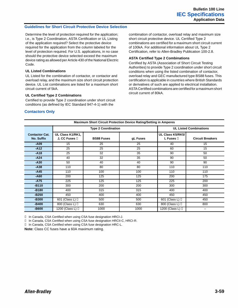
Bulletin 100 LineIEC Specifications
3-59
Application Data
Guidelines for Short Circuit Protective Device Selection
Contactors Only
➊ In Canada, CSA Certified when using CSA fuse designation HRCI-J.➋ In Canada, CSA Certified when using CSA fuse designation HRCII-C, HRCI-R.➌ In Canada, CSA Certified when using CSA fuse designation HRC-L.
Note: Class CC fuses have a 60A maximum rating.
Determine the level of protection required for the application;i.e., is Type 2 Coordination, ASTA Certification or UL Listingof the application required? Select the protective devicerequired for the application from the column labeled for thelevel of protection required. For U.S. applications, in no caseshould the protective device selected exceed the maximumdevice rating as allowed per Article 430 of the National ElectricCode.
UL Listed CombinationsUL Listed for the combination of contactor, or contactor andoverload relay, and the maximum size short circuit protectiondevice. UL List combinations are listed for a maximum shortcircuit current of 5kA.
UL Certified Type 2 CombinationsCertified to provide Type 2 coordination under short circuitconditions (as defined by IEC Standard 947-4-1) with the
combination of contactor, overload relay and maximum sizeshort circuit protective device. UL Certified Type 2combinations are certified for a maximum short circuit currentof 100kA. For additional information about UL Type 2Certification, refer to Allen-Bradley Publication 100-2.8.
ASTA Certified Type 2 CombinationsCertified by ASTA (Association of Short Circuit TestingAuthorities) to provide Type 2 coordination under short circuitconditions when using the listed combination of contactor,overload relay and GEC manufactured type BS88 fuses. Thiscertification is applicable in countries where British Standardsor derivatives of such are applied to electrical installation.ASTA Certified combinations are certified for a maximum shortcircuit current of 80kA.
Maximum Short Circuit Protection Device Rating/Setting in Amperes
Contactor Cat.No. Suffix
Type 2 Coordination UL Listed Combinations
UL Class K1/RK1,J, CC Fuses ➊ BS88 Fuses gL Fuses
UL Class K5/RK5/L Fuses ➋ Circuit Breakers
-A09 15 25 25 40 15
-A12 25 25 25 60 15
-A18 25 32 35 90 50
-A24 40 32 35 90 50
-A30 50 40 40 90 90
-A38 110 80 80 110 110
-A45 110 100 100 110 110
-A60 200 125 125 200 175
-A75 225 125 125 225 200
-B110 300 200 200 300 300
-B180 400 315 315 400 400
-B250 450 400 400 450 450
-B300 601 (Class L) ➌ 500 500 601 (Class L) ➌ 450
-B400 800 (Class L) ➌ 630 630 800 (Class L) ➌ 800
-B600 1200 (Class L) ➌ 1000 1000 1200 (Class L) ➌ –
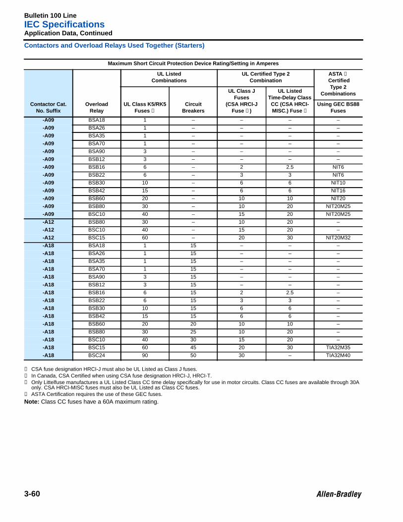
Bulletin 100 LineIEC Specifications
3-60
Application Data, Continued
Contactors and Overload Relays Used Together (Starters)
➊ CSA fuse designation HRCI-J must also be UL Listed as Class J fuses.➋ In Canada, CSA Certified when using CSA fuse designation HRCI-J, HRCI-T.➌ Only Littelfuse manufactures a UL Listed Class CC time delay specifically for use in motor circuits. Class CC fuses are available through 30A
only. CSA HRCI-MISC fuses must also be UL Listed as Class CC fuses.➍ ASTA Certification requires the use of these GEC fuses.
Note: Class CC fuses have a 60A maximum rating.
Maximum Short Circuit Protection Device Rating/Setting in Amperes
Contactor Cat.No. Suffix
OverloadRelay
UL ListedCombinations
UL Certified Type 2Combination
ASTA ➍
CertifiedType 2
Combinations
UL Class K5/RK5Fuses ➊
CircuitBreakers
UL Class JFuses
(CSA HRCI-JFuse ➋)
UL ListedTime-Delay ClassCC (CSA HRCI-MISC.) Fuse ➌
Using GEC BS88Fuses
-A09 BSA18 1 – – – –
-A09 BSA26 1 – – – –
-A09 BSA35 1 – – – –
-A09 BSA70 1 – – – –
-A09 BSA90 3 – – – –
-A09 BSB12 3 – – – –
-A09 BSB16 6 – 2 2.5 NIT6
-A09 BSB22 6 – 3 3 NIT6
-A09 BSB30 10 – 6 6 NIT10
-A09 BSB42 15 – 6 6 NIT16
-A09 BSB60 20 – 10 10 NIT20
-A09 BSB80 30 – 10 20 NIT20M25
-A09 BSC10 40 – 15 20 NIT20M25
-A12 BSB80 30 – 10 20 –
-A12 BSC10 40 – 15 20 –
-A12 BSC15 60 – 20 30 NIT20M32
-A18 BSA18 1 15 – – –
-A18 BSA26 1 15 – – –
-A18 BSA35 1 15 – – –
-A18 BSA70 1 15 – – –
-A18 BSA90 3 15 – – –
-A18 BSB12 3 15 – – –
-A18 BSB16 6 15 2 2.5 –
-A18 BSB22 6 15 3 3 –
-A18 BSB30 10 15 6 6 –
-A18 BSB42 15 15 6 6 –
-A18 BSB60 20 20 10 10 –
-A18 BSB80 30 25 10 20 –
-A18 BSC10 40 30 15 20 –
-A18 BSC15 60 45 20 30 TIA32M35
-A18 BSC24 90 50 30 – TIA32M40
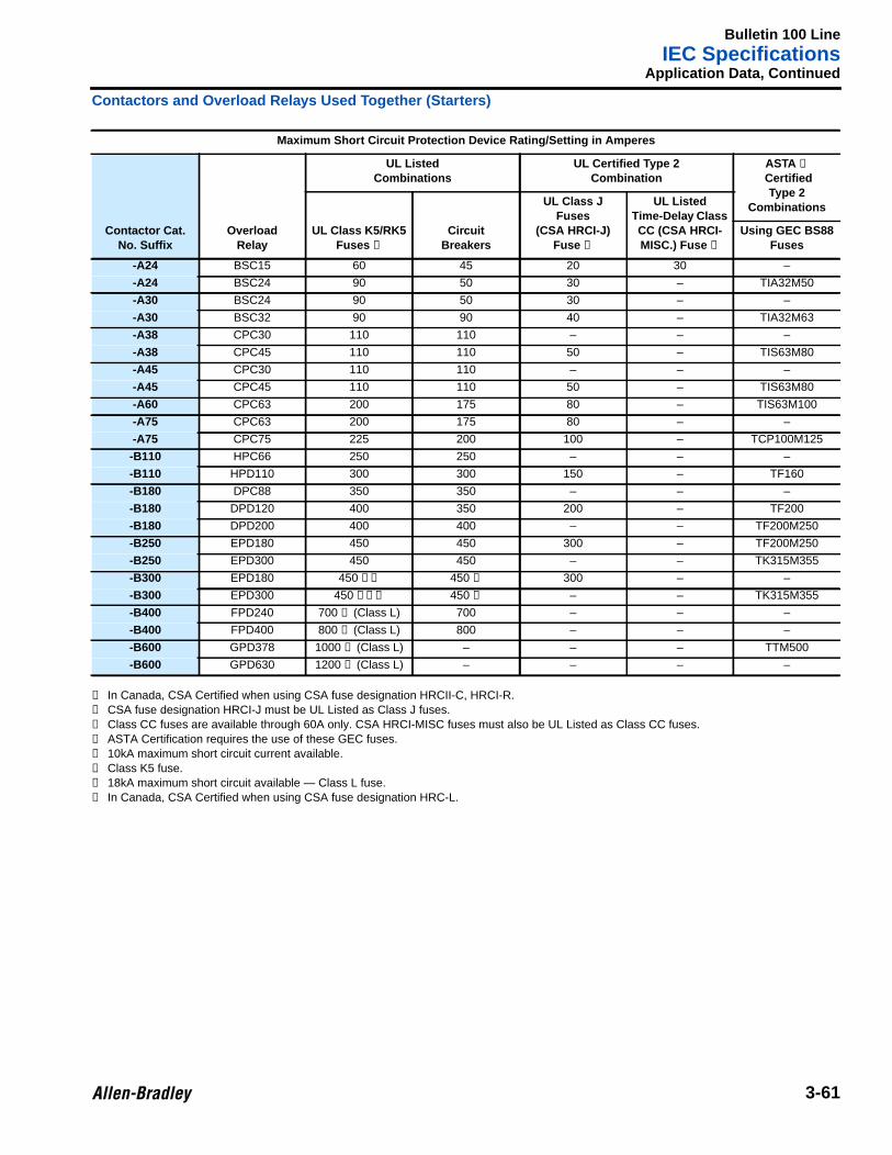
Bulletin 100 LineIEC Specifications
3-61
Application Data, Continued
Contactors and Overload Relays Used Together (Starters)
➊ In Canada, CSA Certified when using CSA fuse designation HRCII-C, HRCI-R.➋ CSA fuse designation HRCI-J must be UL Listed as Class J fuses.➌ Class CC fuses are available through 60A only. CSA HRCI-MISC fuses must also be UL Listed as Class CC fuses.➍ ASTA Certification requires the use of these GEC fuses.➎ 10kA maximum short circuit current available.➏ Class K5 fuse.➐ 18kA maximum short circuit available — Class L fuse.➑ In Canada, CSA Certified when using CSA fuse designation HRC-L.
Maximum Short Circuit Protection Device Rating/Setting in Amperes
Contactor Cat.No. Suffix
OverloadRelay
UL ListedCombinations
UL Certified Type 2Combination
ASTA ➍
CertifiedType 2
Combinations
UL Class K5/RK5Fuses ➊
CircuitBreakers
UL Class JFuses
(CSA HRCI-J)Fuse ➋
UL ListedTime-Delay ClassCC (CSA HRCI-MISC.) Fuse ➌
Using GEC BS88Fuses
-A24 BSC15 60 45 20 30 –
-A24 BSC24 90 50 30 – TIA32M50
-A30 BSC24 90 50 30 – –
-A30 BSC32 90 90 40 – TIA32M63
-A38 CPC30 110 110 – – –
-A38 CPC45 110 110 50 – TIS63M80
-A45 CPC30 110 110 – – –
-A45 CPC45 110 110 50 – TIS63M80
-A60 CPC63 200 175 80 – TIS63M100
-A75 CPC63 200 175 80 – –
-A75 CPC75 225 200 100 – TCP100M125
-B110 HPC66 250 250 – – –
-B110 HPD110 300 300 150 – TF160
-B180 DPC88 350 350 – – –
-B180 DPD120 400 350 200 – TF200
-B180 DPD200 400 400 – – TF200M250
-B250 EPD180 450 450 300 – TF200M250
-B250 EPD300 450 450 – – TK315M355
-B300 EPD180 450 ➎➏ 450 ➎ 300 – –
-B300 EPD300 450 ➎➏➐ 450 ➎ – – TK315M355
-B400 FPD240 700 ➑ (Class L) 700 – – –
-B400 FPD400 800 ➑ (Class L) 800 – – –
-B600 GPD378 1000 ➑ (Class L) – – – TTM500
-B600 GPD630 1200 ➑ (Class L) – – – –
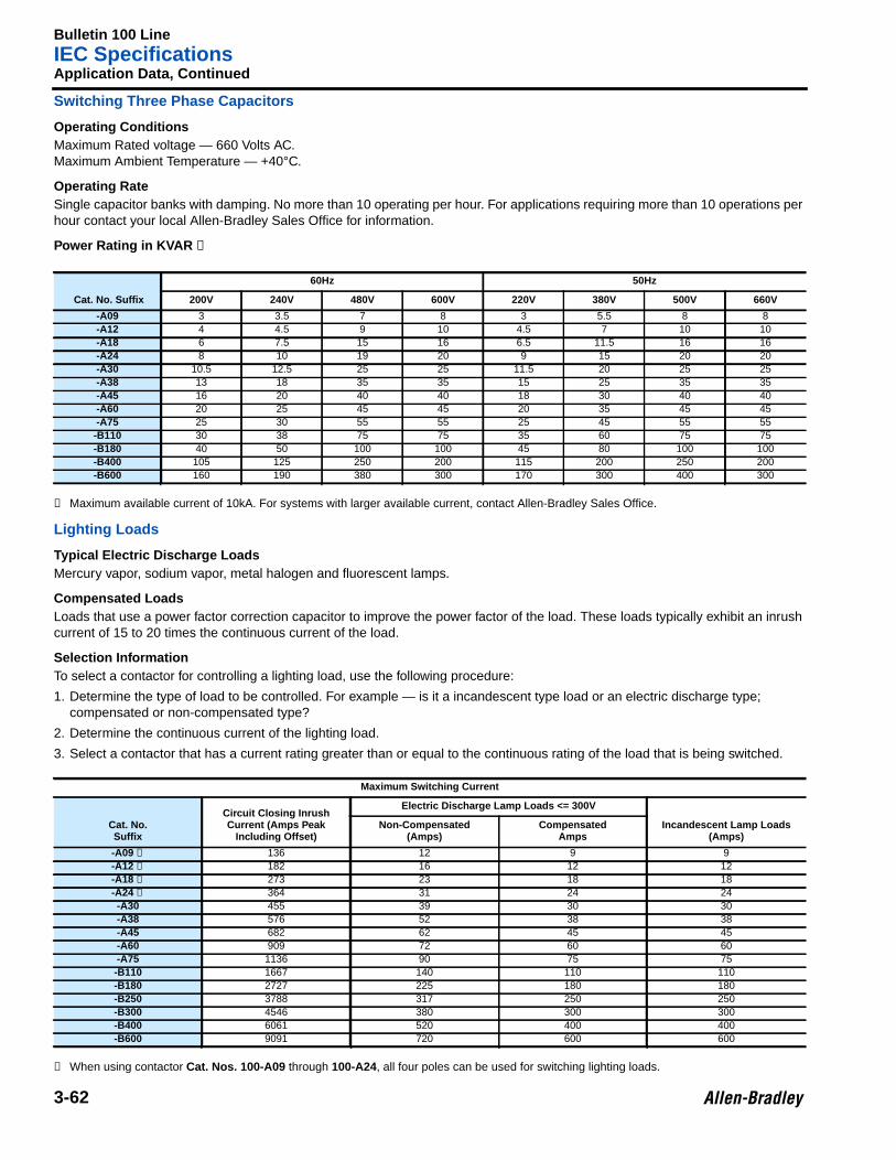
Bulletin 100 LineIEC Specifications
3-62
Application Data, Continued
Switching Three Phase Capacitors
Operating ConditionsMaximum Rated voltage — 660 Volts AC.Maximum Ambient Temperature — +40°C.
Operating RateSingle capacitor banks with damping. No more than 10 operating per hour. For applications requiring more than 10 operations perhour contact your local Allen-Bradley Sales Office for information.
Power Rating in KVAR ➊
➊ Maximum available current of 10kA. For systems with larger available current, contact Allen-Bradley Sales Office.
Lighting Loads
Typical Electric Discharge LoadsMercury vapor, sodium vapor, metal halogen and fluorescent lamps.
Compensated LoadsLoads that use a power factor correction capacitor to improve the power factor of the load. These loads typically exhibit an inrushcurrent of 15 to 20 times the continuous current of the load.
Selection InformationTo select a contactor for controlling a lighting load, use the following procedure:
1. Determine the type of load to be controlled. For example — is it a incandescent type load or an electric discharge type;compensated or non-compensated type?
2. Determine the continuous current of the lighting load.
3. Select a contactor that has a current rating greater than or equal to the continuous rating of the load that is being switched.
➊ When using contactor Cat. Nos. 100-A09 through 100-A24, all four poles can be used for switching lighting loads.
Cat. No. Suffix
60Hz 50Hz
200V 240V 480V 600V 220V 380V 500V 660V
-A09 3 3.5 7 8 3 5.5 8 8-A12 4 4.5 9 10 4.5 7 10 10-A18 6 7.5 15 16 6.5 11.5 16 16-A24 8 10 19 20 9 15 20 20-A30 10.5 12.5 25 25 11.5 20 25 25-A38 13 18 35 35 15 25 35 35-A45 16 20 40 40 18 30 40 40-A60 20 25 45 45 20 35 45 45-A75 25 30 55 55 25 45 55 55
-B110 30 38 75 75 35 60 75 75-B180 40 50 100 100 45 80 100 100-B400 105 125 250 200 115 200 250 200-B600 160 190 380 300 170 300 400 300
Maximum Switching Current
Cat. No.Suffix
Circuit Closing InrushCurrent (Amps Peak
Including Offset)
Electric Discharge Lamp Loads <= 300V
Incandescent Lamp Loads(Amps)
Non-Compensated(Amps)
CompensatedAmps
-A09 ➊ 136 12 9 9-A12 ➊ 182 16 12 12-A18 ➊ 273 23 18 18-A24 ➊ 364 31 24 24-A30 455 39 30 30-A38 576 52 38 38-A45 682 62 45 45-A60 909 72 60 60-A75 1136 90 75 75-B110 1667 140 110 110-B180 2727 225 180 180-B250 3788 317 250 250-B300 4546 380 300 300-B400 6061 520 400 400-B600 9091 720 600 600
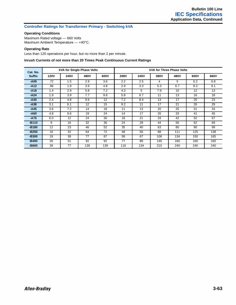
Bulletin 100 LineIEC Specifications
3-63
Application Data, Continued
Controller Ratings for Transformer Primary - Switching kVA
Operating ConditionsMaximum Rated voltage — 660 VoltsMaximum Ambient Temperature — +40°C.
Operating RateLess than 120 operations per hour, but no more than 2 per minute.
Inrush Currents of not more than 20 Times Peak Continuous Current Ratings
Cat. No.Suffix
kVA for Single Phase Volts kVA for Three Phase Volts
120V 240V 480V 600V 208V 240V 380V 480V 600V 660V
-A09 .72 1.5 2.9 3.6 2.2 2.5 4 5 6.2 6.8
-A12 .96 1.9 3.9 4.8 2.9 3.3 5.3 6.7 8.3 9.1
-A18 1.4 2.9 5.8 7.2 4.3 5 7.9 10 12 13
-A24 1.9 3.9 7.7 9.6 5.8 6.7 11 13 16 18
-A30 2.4 4.8 9.6 12 7.2 8.4 13 17 20 23
-A38 3.1 6.1 12 15 9.2 11 17 21 26 29
-A45 3.6 7.2 14 18 11 13 20 25 31 34
-A60 4.8 9.6 19 24 14 17 26 33 41 45
-A75 6.0 12 24 30 18 21 33 42 52 57
-B110 9 16 32 36 24 28 44 56 62 69
-B180 12 23 46 52 35 40 63 80 90 99
-B250 16 32 64 72 48 56 88 111 125 138
-B300 19 39 77 87 58 67 106 134 150 165
-B400 26 51 92 92 77 89 140 160 160 160
-B600 39 77 139 139 116 134 210 240 240 240
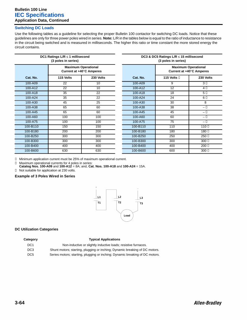
Bulletin 100 LineIEC Specifications
3-64
Application Data, Continued
Switching DC LoadsUse the following tables as a guideline for selecting the proper Bulletin 100 contactor for switching DC loads. Notice that theseguidelines are only for three power poles wired in series. Note: L/R in the tables below is equal to the ratio of inductance to resistancein the circuit being switched and is measured in milliseconds. The higher this ratio or time constant the more stored energy thecircuit contains.
➊ Minimum application current must be 25% of maximum operational current.➋ Maximum operational currents for 4 poles in series:
Catalog Nos. 100-A09 and 100-A12 = 8A; and, Cat. Nos. 100-A18 and 100-A24 = 15A.➌ Not suitable for application at 230 volts.
Example of 3 Poles Wired in Series
DC Utilization Categories
DC1 Ratings L/R ≤ 1 millisecond(3 poles in series)
DC3 & DC5 Ratings L/R ≤ 15 millisecond(3 poles in series)
Cat. No.
Maximum OperationalCurrent at +40 °C Amperes
Cat. No.
Maximum OperationalCurrent at +40 °C Amperes
115 Volts 230 Volts 115 Volts ➊ 230 Volts
100-A09 22 10 100-A09 9 3 ➋
100-A12 22 10 100-A12 12 4 ➋
100-A18 35 22 100-A18 18 5 ➋
100-A24 35 22 100-A24 24 6 ➋
100-A30 45 25 100-A30 30 8
100-A38 65 60 100-A38 38 – ➌
100-A45 65 60 100-A45 45 – ➌
100-A60 100 100 100-A60 60 – ➌
100-A75 100 100 100-A75 75 – ➌
100-B110 150 150 100-B110 110 110 ➊
100-B180 200 200 100-B180 180 180 ➊
100-B250 300 300 100-B250 250 250 ➊
100-B300 300 300 100-B300 300 300 ➊
100-B400 400 400 100-B400 400 200 ➊
100-B600 630 630 100-B600 600 300 ➊
Category Typical Applications
DC1 Non-inductive or slightly inductive loads; resistive furnaces.
DC3 Shunt motors; starting, plugging or inching; Dynamic breaking of DC motors.
DC5 Series motors; starting, plugging or inching; Dynamic breaking of DC motors.
L1
T1
L2
T2
L3
T3
Load
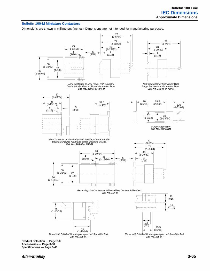
Bulletin 100 LineIEC Dimensions
3-65
3 Approximate Dimensions
Bulletin 100-M Miniature ContactorsDimensions are shown in millimeters (inches). Dimensions are not intended for manufacturing purposes.
Product Selection — Page 3-6Accessories — Page 3-38Specifications — Page 3-48
78(3-7/64)
48(1-29/32)
4(1/16)
10(25/64)
19.5(25/32)
22(7/8)
23.5(15/16)41
(1-41/64)
45(1-13/16)
4(1/16)
5(3/16)
31.5(1-1/4)
11(7/16)
5(3/16)
56(2-15/64)
47(1-7/8)
77(3-5/64)
74(2-59/64)
48(1-29/32)
50(1-31/32)
67(2-43/64)
4(1/16)
45(1-13/16)
5(3/16)
50(1-31/32)
56(2-15/64)
77(3-5/64
)74(2-59/64)
48(1-29/32)
4(1/16)
45(1-13/16)
120(4-51/64)
32(1-9/32)
47(1-7/8)
45(1-13/16)
4(1/16)
4(1/16)
11(7/16)
30(1-13/64)
90(3-39/64)
Mini-Contactor or Mini-Relay With AuxiliaryContact Adder Deck or Timer Mounted to Front.
Cat. No. 100-M or 700-M
Mini-Contactor or Mini-Relay WithSurge Suppressor Mounted to Front.
Cat. No. 100-M or 700-M
Mini-Contactor or Mini-Relay With Auxiliary Contact AdderDeck Mounted to Front and Timer Mounted to Side.
Cat. No. 100-M or 700-M
Surge SuppressorCat. No. 199-MSM
Reversing Mini-Contactors With Auxiliary Contact Adder Deck.Cat. No. 104-M
Timer With DIN Rail Mounting Adapter on 35mm DIN Rail.Cat. No. 196-MT
Timer With DIN Rail Mounting Adapter on 35mm DIN Rail.Cat. No. 196-MT
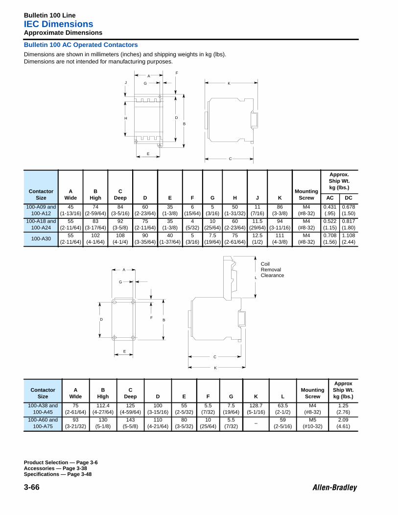
Bulletin 100 LineIEC Dimensions
3-66
Approximate Dimensions
Bulletin 100 AC Operated ContactorsDimensions are shown in millimeters (inches) and shipping weights in kg (lbs).Dimensions are not intended for manufacturing purposes.
ContactorSize
AWide
BHigh
CDeep D E F G H J K
MountingScrew
Approx.Ship Wt.kg (lbs.)
AC DC
100-A09 and100-A12
45(1-13/16)
74(2-59/64)
84(3-5/16)
60(2-23/64)
35(1-3/8)
6(15/64)
5(3/16)
50(1-31/32)
11(7/16)
86(3-3/8)
M4(#8-32)
0.431(.95)
0.678(1.50)
100-A18 and100-A24
55(2-11/64)
83(3-17/64)
92(3-5/8)
75(2-11/64)
35(1-3/8)
4(5/32)
10(25/64)
60(2-23/64)
11.5(29/64)
94(3-11/16)
M4(#8-32)
0.522(1.15)
0.817(1.80)
100-A3055
(2-11/64)102
(4-1/64)108
(4-1/4)90
(3-35/64)40
(1-37/64)5
(3/16)7.5
(19/64)75
(2-61/64)12.5(1/2)
111(4-3/8)
M4(#8-32)
0.708(1.56)
1.108(2.44)
ContactorSize
AWIde
BHIgh
CDeep D E F G K L
MountingScrew
ApproxShip Wt.kg (lbs.)
100-A38 and100-A45
75(2-61/64)
112.4(4-27/64)
125(4-59/64)
100(3-15/16)
55(2-5/32)
5.5(7/32)
7.5(19/64)
128.7(5-1/16)
63.5(2-1/2)
M4(#8-32)
1.25(2.76)
100-A60 and100-A75
93(3-21/32)
130(5-1/8)
143(5-5/8)
110(4-21/64)
80(3-5/32)
10(25/64)
5.5(7/32)
–59
(2-5/16)M5
(#10-32)2.09
(4.61)
C
K
A
G
F
D
B
E
H
J
Product Selection — Page 3-6Accessories — Page 3-38Specifications — Page 3-48
A
B
C
D
E
F
G
K
L
CoilRemovalClearance
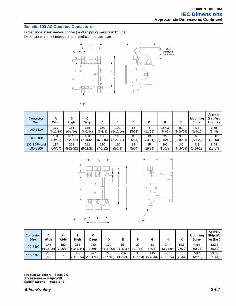
Bulletin 100 LineIEC Dimensions
3-67
Approximate Dimensions, Continued
Bulletin 100 AC Operated ContactorsDimensions in millimeters (inches) and shipping weights in kg (lbs).Dimensions are not intended for manufacturing purposes.
ContactorSize
AWide
BHigh
CDeep D E F G H K
MountingScrew
Approx.Ship Wt.kg (lbs.)
100-B110119
(4-11/16)154
(6-1/16)155
(6-7/64)130
(5-1/8)100
(3-15/16)12
(15/32)9
(11/32)187.3(7-3/8)
62(2-29/64)
M6(1/4-20)
3.85(8.49)
100-B180134
(5-9/32)187.8
(7-25/64)190
(7-31/64)160
(6-5/16)110
(4-21/64)13.9
(35/64)13
(33/64)227
(8-15/16)90
(3-35/64)M6
(1/4-20)7.00
(15.43)
100-B250 and100-B300
154(6-5/64)
226(8-29/32)
212(8-11/32)
180(7-3/32)
130(5-1/8)
18(45/64)
15(19/32)
292(11-1/2)
109(4-19/64)
M8(5/16-18)
8.24(18.17)
ContactorSize
AWide
A1Wide
BHigh
CDeep D E F G H K
MountingScrew
Approx.Ship Wt.kg (lbs.)
100-B400176
(6-15/16)189
(7-29/64)255
(10-3/64)230
(9-3/64)199
(7-27/32)154
(6-1/16)28
(1-7/64)11
(7/16)344
(13-35/64)10.5
(13/32)M10
(3/8-16)13.88
(30.60)
100-B600255(10)
–306
(12-3/64)267
(10-17/32)220
(8-1/16)226
(8-29/32)33
(1-19/64)145
(5-45/64)433
(17-3/64)10
(25/64)M12
(1/2-13)23.32
(51.41)
A
B
C
D
E
F
G
H
K
Lug Kit
CoilRemoval
Clearance
A
B
C
D
E
F
G
H
K
Lug Kit
A1
Product Selection — Page 3-6Accessories — Page 3-38Specifications — Page 3-48
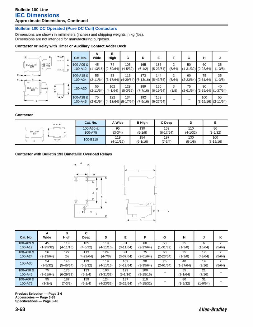
Bulletin 100 LineIEC Dimensions
3-68
Approximate Dimensions, Continued
Bulletin 100 DC Operated (Pure DC Coil) ContactorsDimensions are shown in millimeters (inches) and shipping weights in kg (lbs).Dimensions are not intended for manufacturing purposes.
Contactor or Relay with Timer or Auxiliary Contact Adder Deck
Contactor
Contactor with Bulletin 193 Bimetallic Overload Relays
Cat. No.A
WideB
High C D E F G H J
100-A09 &100-A12
45(1-13/16)
74(2-59/64)
105(4-5/32)
165(6-1/2)
136(5-23/64)
2(5/64)
50(1-31/32)
60(2-23/64)
35(1-3/8)
100-A18 &100-A24
55(2-11/64)
83(3-17/64)
113(4-29/64)
173(6-13/16)
144(5-43/64)
2(5/64)
60(2-23/64)
75(2-61/64)
35(1-3/8)
100-A3055
(2-11/64)102
(4-1/64)129
(5-3/32)189
(7-7/16)160
(6-19/64)3
(1/8)75
(2-61/64)90
(3-35/64)40
(1-37/64)
100-A38 &100-A45
75(2-61/64)
122(4-13/64)
134(5-17/64)
192(7-9/16)
163(6-27/64)
– –100
(3-15/16)55
(2-11/64)
Cat. No. A Wide B High C Deep D E
100-A60 &100-A75
95(3-3/4)
130(5-1/8)
159(6-17/64)
110(4-1/32)
80(3-5/32)
100-B110119
(4-11/16)154
(6-1/16)197
(7-3/4)130
(5-1/8)100
(3-15/16)
Cat. No.A
WideB
HighC
Deep D E F G H J K
100-A09 &100-A12
45(1-25/32)
119(4-11/16)
105(4-5/32)
119(4-11/16)
81(3-11/64)
60(2-23/64)
50(1-31/32)
35(1-3/8)
6(15/64)
2(5/64)
100-A18 &100-A24
56(2-13/64)
127(5)
113(4-29/64)
124(4-7/8)
91(3-37/64)
75(2-61/64)
60(2-23/64)
35(1-3/8)
17(43/64)
2(5/64)
100-A3054
(2-5/32)145
(5-45/64)129
(5-3/32)119
(4-11/16)109
(4-19/64)90
(3-35/64)75
(2-61/64)40
(1-37/64)14
(9/16)2
(5/64)
100-A38 &100-A45
75(2-61/64)
175(6-29/32)
133(5-1/4)
103(3-31/32)
129(5-1/16)
100(3-15/16)
–55
(2-1/64)21
(7/16) –
100-A60 &100-A75
95(3-3/4)
187(7-3/8)
159(6-1/4)
124(4-23/32)
137(5-25/64)
110(4-15/32)
–80
(3-5/32)31
(1-9/64) –
D
F C
A
B
F C
E
G H
J
BULLETIN100
196-FTA196-FTB
195-FABULLETIN100
A
B
C
D
E
BULLETIN100
A
B
C
D
E
F
G
H
JK
Product Selection — Page 3-6Accessories — Page 3-38Specifications — Page 3-48
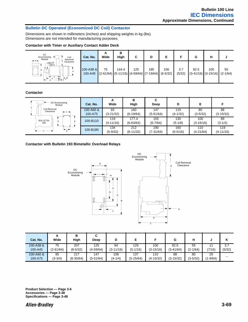
Bulletin 100 LineIEC Dimensions
3-69
Approximate Dimensions, Continued
Bulletin DC Operated (Economized DC Coil) ContactorDimensions are shown in millimeters (inches) and shipping weights in kg (lbs).Dimensions are not intended for manufacturing purposes.
Contactor with Timer or Auxiliary Contact Adder Deck
Contactor
Contactor with Bulletin 193 Bimetallic Overload Relays
Cat. No.A
WideB
High C D E F G H J
100-A38 &100-A45
75(2-61/64)
144.4(5-11/16)
125(4-59/64)
185(7-19/64)
156(6-5/32)
3.7(5/32)
92.5(3-41/16)
100(3-15/16)
55(2-1/64)
Cat. No.A
WideB
HighC
Deep D E F
100-A60 &100-A75
93(3-21/32)
160(6-19/64)
147(5-51/64)
110(4-1/32)
80(3-5/32)
88(3-15/32)
100-B110119
(4-11/16)177.4
(6-63/64)155
(6-7/64)130
(5-1/8)100
(3-15/16)89
(3-1/2)
100-B180134
(5-9/32)212
(8-11/32)190
(7-31/64)160
(6-5/16)110
(4-21/64)119
(4-11/16)
Cat. No.A
WideB
HighC
Deep D E F G H J K
100-A38 &100-A45
75(2-61/64)
207(8-5/32)
125(4-59/64)
94(3-11/16)
129(5-1/16)
100(3-15/16)
92.5(3-41/64)
55(2-1/64)
11(7/16)
3.7(5/32)
100-A60 &100-A75
95(3-3/4)
217(8-35/64)
147(5-51/64)
108(4-1/4)
137(5-25/64)
110(4-15/32)
88(3-15/32)
80(3-5/32)
29(1-9/64)
–
A
B
C
DE
F
G
J
DCEconomizing
ModuleCoil
RemovalClearance196-FT
195-F
H
A
B
C
D
E
F
DC EconomizingModule
Coil RemovalClearance
BULLETIN100
A
B
C
D
E
F
G
H
JK
GCoil Removal
Clearance
DCEconomizing
Module
DCEconomizing
Module
Product Selection — Page 3-6Accessories — Page 3-38Specifications — Page 3-48
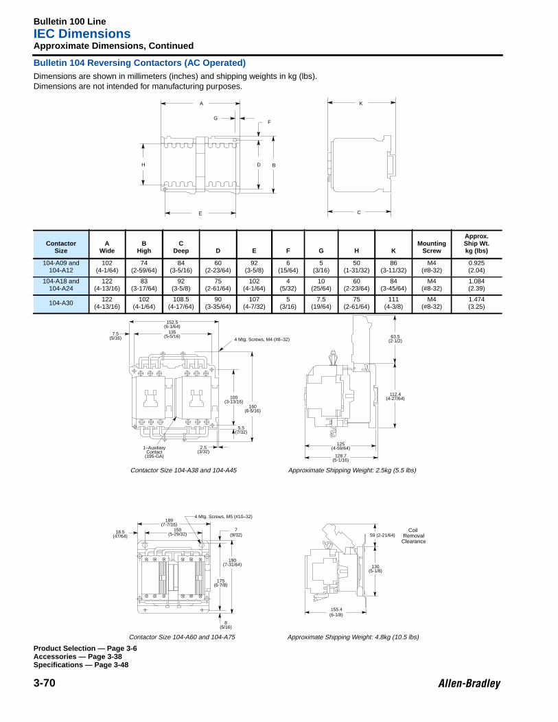
Bulletin 100 LineIEC Dimensions
3-70
Approximate Dimensions, Continued
Bulletin 104 Reversing Contactors (AC Operated)Dimensions are shown in millimeters (inches) and shipping weights in kg (lbs).Dimensions are not intended for manufacturing purposes.
ContactorSize
AWide
BHigh
CDeep D E F G H K
MountingScrew
Approx.Ship Wt.kg (lbs)
104-A09 and104-A12
102(4-1/64)
74(2-59/64)
84(3-5/16)
60(2-23/64)
92(3-5/8)
6(15/64)
5(3/16)
50(1-31/32)
86(3-11/32)
M4(#8-32)
0.925(2.04)
104-A18 and104-A24
122(4-13/16)
83(3-17/64)
92(3-5/8)
75(2-61/64)
102(4-1/64)
4(5/32)
10(25/64)
60(2-23/64)
84(3-45/64)
M4(#8-32)
1.084(2.39)
104-A30 122(4-13/16)
102(4-1/64)
108.5(4-17/64)
90(3-35/64)
107(4-7/32)
5(3/16)
7.5(19/64)
75(2-61/64)
111(4-3/8)
M4(#8-32)
1.474(3.25)
A
GF
D B
E
H
C
K
Product Selection — Page 3-6Accessories — Page 3-38Specifications — Page 3-48
152.5(6-1/64)
135(5-5/16)7.5
(5/16)
160(6-5/16)
100(3-13/16)
5.5(7/32)
2.5(3/32)
1–AuxiliaryContact
(195-GA)
63.5(2-1/2)
112.4(4-27/64)
125(4-59/64)
128.7(5-1/16)
4 Mtg. Screws, M4 (#8–32)
4 Mtg. Screws, M5 (#10–32)189
(7-7/16)150
(5-29/32) (9/32)718.5
(47/64)
190(7-31/64)
175(6-7/8)
59 (2-21/64)
130(5-1/8)
155.4(6-1/8)
Coil Removal
Clearance
8(5/16)
Contactor Size 104-A38 and 104-A45 Approximate Shipping Weight: 2.5kg (5.5 lbs)
Contactor Size 104-A60 and 104-A75 Approximate Shipping Weight: 4.8kg (10.5 lbs)

Bulletin 100 LineIEC Dimensions
3-71
Approximate Dimensions, Continued
Bulletin 104 Reversing Contactors (AC Operated), ContinuedDimensions are shown in millimeters (inches) and shipping weights in kg (lbs).Dimensions are not intended for manufacturing purposes.
ContactorSize
AWide
BHigh
CDeep D E F G H K
MountingScrew
Approx.Ship Wt.kg (lbs)
104-B110239
(9-27/64)225
(8-33/64)164
(6-29/64)205
(8-1/16)216
(8-1/2)10
(25/64)11.9
(15/32)65
(2-9/16)187.4(7-1/2)
M6(1/4-20)
8.2(18.1)
104-B180269
(10-19/32)255
(10-3/64)200
(7-7/8)235
(9-1/4)245
(9-21/32)10
(25/64)12
(15/32)100
(3-15/16)227
(9-5/64)M6
(1/4-20)15.1
(32.2)
104-B250 and104-B300
311(12-15/64)
270(10-5/8)
221(8-45/64)
250(9-27/32)
280(11-1/64)
10(25/64)
15.5(39/64)
108(4-19/64)
292(11-31/64)
M8(5/16-18)
21.1(46.5)
ContactorSize
AWide
BHigh
CDeep D E F G K
MountingScrew
Approx.Ship Wt.kg (lbs)
104-B400426
(16-49/64)275
(10-13/16)250
(9-27/32)230
(9-3/64)400
(15-3/4)26
(1-1/64)13
(33/64)344
(13-35/64)M10
(3/8-16)33.6
(74.0)
104-B600595
(23-13/32)346
(13-5/8)290
(11-7/16)263
(10-11/32)558
(21-31/32)41.6
(1-41/64)18.2
(23/32)433
(17-3/64)M12
(1/2-13)59.4
(131.0)
A
B
D
E
F
G
K
Lug Kit
C
HCoil
RemovalClearance
A
B
C
D
EF
G
K
Product Selection — Page 3-6Accessories — Page 3-38Specifications — Page 3-48
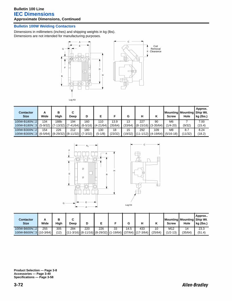
Bulletin 100 LineIEC Dimensions
3-72
Approximate Dimensions, Continued
Bulletin 100W Welding ContactorsDimensions in millimeters (inches) and shipping weights in kg (lbs).Dimensions are not intended for manufacturing purposes.
ContactorSize
AWide
BHigh
CDeep D E F G H K
MountingScrew
MountingHole
Approx.Ship Wt.kg (lbs.)
100W-B180N⊗2100W-B180N⊗3
134(5-9/32)
188b(7-13/32)
194(7-41/64)
160(6-5/16)
110(4-21/64)
13.9(35/64)
13(33/64)
227(8-15/16)
90(3-35/64)
M6(1/4-20)
7(9/32)
7.00(15.4)
100W-B300N⊗2100W-B300N⊗3
154(6-5/64)
226(8-29/32)
212(8-11/32)
180(7-3/32)
130(5-1/8)
18(23/32)
15(19/32)
292(11-1/12)
109(4-19/64)
M8(5/16-18)
8.7(11/32)
8.24(18.2)
ContactorSize
AWide
BHigh
CDeep D E F G H K
MountingScrew
MountingHole
Approx..Ship Wt .kg (lbs.)
100W-B600N⊗2100W-B600N⊗3
255(10-3/64)
305(12)
284(11-3/16)
220(8-11/16)
226(8-29/32)
33(1-19/64)
14.5(37/64)
433(17-3/64)
10(25/64)
M12(1/2-13)
14(35/64)
23.3(51.4)
A
B
C
D
E
F
G
H
K
Lug Kit
CoilRemoval
Clearance
A
B
C
D
E
F
G
H
K
Lug Kit
A1
Product Selection — Page 3-8Accessories — Page 3-40Specifications — Page 3-58
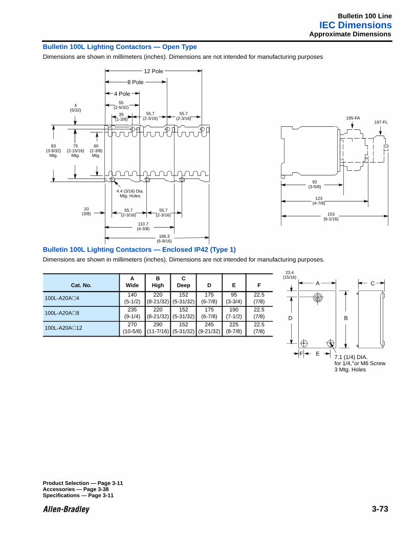
Bulletin 100 LineIEC Dimensions
3-73
Approximate Dimensions
Bulletin 100L Lighting Contactors — Open TypeDimensions are shown in millimeters (inches). Dimensions are not intended for manufacturing purposes
Bulletin 100L Lighting Contactors — Enclosed IP42 (Type 1)Dimensions are shown in millimeters (inches). Dimensions are not intended for manufacturing purposes.
55.7(2-3/16)
92(3-5/8)
123(4-7/8)
153(6-1/16)
166.3(6-9/16)
197-FL195-FA
55.7(2-3/16)
110.7(4-3/8)
10(3/8)
4.4 (3/16) Dia.Mtg. Holes
60(2-3/8)Mtg.
75(2-15/16)
Mtg.
83(3-9/32)
Mtg.
55(2-5/32)
35(1-3/8)
55.7(2-3/16)
55.7(2-3/16)
4(5/32)
4 Pole
8 Pole
12 Pole
23.4(15/16)
B
A
D
EF7.1 (1/4) DIA.for 1/4,″or M6 Screw3 Mtg. Holes
CCat. No.A
WideB
HighC
Deep D E F
100L-A20A⊗4 140(5-1/2)
220(8-21/32)
152(5-31/32)
175(6-7/8)
95(3-3/4)
22.5(7/8)
100L-A20A⊗8235
(9-1/4)220
(8-21/32)152
(5-31/32)175
(6-7/8)190
(7-1/2)22.5(7/8)
100L-A20A⊗12270
(10-5/8)290
(11-7/16)152
(5-31/32)245
(9-21/32)225
(8-7/8)22.5(7/8)
Product Selection — Page 3-11Accessories — Page 3-38Specifications — Page 3-11
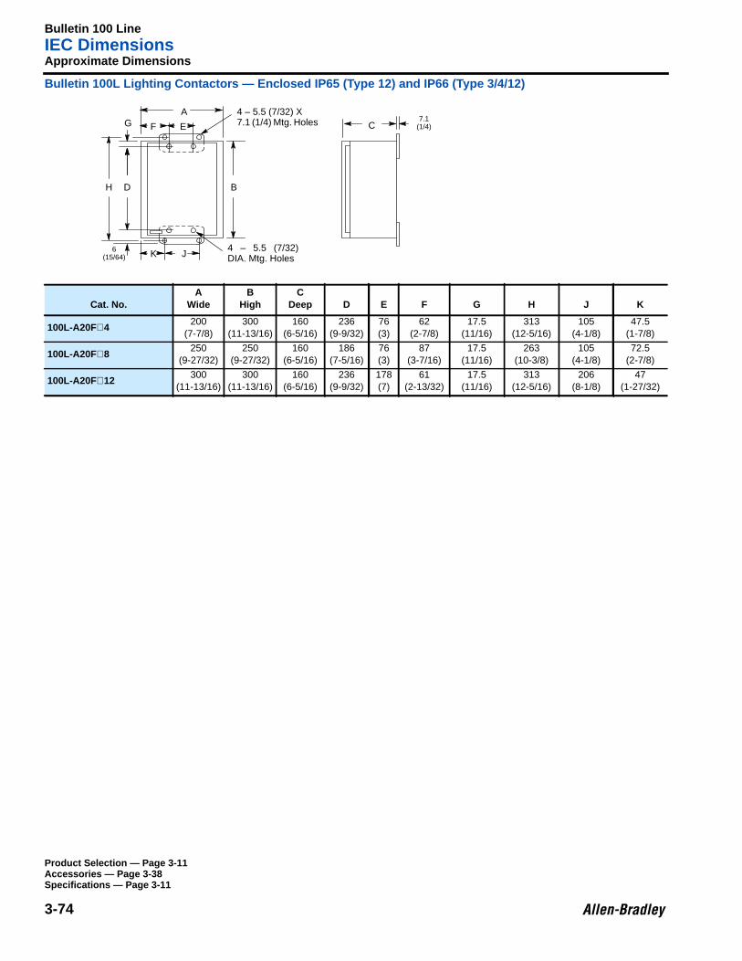
Bulletin 100 LineIEC Dimensions
3-74
Approximate Dimensions
Bulletin 100L Lighting Contactors — Enclosed IP65 (Type 12) and IP66 (Type 3/4/12)
Cat. No.A
WideB
HighC
Deep D E F G H J K
100L-A20F⊗4200
(7-7/8)300
(11-13/16)160
(6-5/16)236
(9-9/32)76(3)
62(2-7/8)
17.5(11/16)
313(12-5/16)
105(4-1/8)
47.5(1-7/8)
100L-A20F⊗8250
(9-27/32)250
(9-27/32)160
(6-5/16)186
(7-5/16)76(3)
87(3-7/16)
17.5(11/16)
263(10-3/8)
105(4-1/8)
72.5(2-7/8)
100L-A20F⊗12300
(11-13/16)300
(11-13/16)160
(6-5/16)236
(9-9/32)178(7)
61(2-13/32)
17.5(11/16)
313(12-5/16)
206(8-1/8)
47(1-27/32)
A
EFG
DH
6(15/64) K J
B
4 – 5.5 (7/32) X 7.1 (1/4) Mtg. Holes
4 – 5.5 (7/32)DIA. Mtg. Holes
C7.1
(1/4)
Product Selection — Page 3-11Accessories — Page 3-38Specifications — Page 3-11
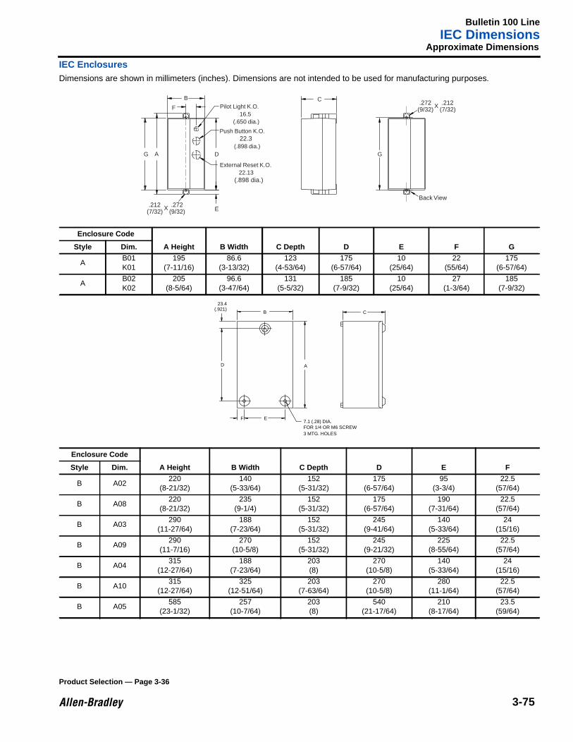
Bulletin 100 LineIEC Dimensions
3-75
Approximate Dimensions
IEC EnclosuresDimensions are shown in millimeters (inches). Dimensions are not intended to be used for manufacturing purposes.
Enclosure Code
A Height B Width C Depth D E F GStyle Dim.
AB01K01
195(7-11/16)
86.6(3-13/32)
123(4-53/64)
175(6-57/64)
10(25/64)
22(55/64)
175(6-57/64)
AB02K02
205(8-5/64)
96.6(3-47/64)
131(5-5/32)
185(7-9/32)
10(25/64)
27(1-3/64)
185(7-9/32)
Enclosure Code
A Height B Width C Depth D E FStyle Dim.
B A02220
(8-21/32)140
(5-33/64)152
(5-31/32)175
(6-57/64)95
(3-3/4)22.5
(57/64)
B A08220
(8-21/32)235
(9-1/4)152
(5-31/32)175
(6-57/64)190
(7-31/64)22.5
(57/64)
B A03290
(11-27/64)188
(7-23/64)152
(5-31/32)245
(9-41/64)140
(5-33/64)24
(15/16)
B A09290
(11-7/16)270
(10-5/8)152
(5-31/32)245
(9-21/32)225
(8-55/64)22.5
(57/64)
B A04315
(12-27/64)188
(7-23/64)203(8)
270(10-5/8)
140(5-33/64)
24(15/16)
B A10315
(12-27/64)325
(12-51/64)203
(7-63/64)270
(10-5/8)280
(11-1/64)22.5
(57/64)
B A05585
(23-1/32)257
(10-7/64)203(8)
540(21-17/64)
210(8-17/64)
23.5(59/64)
B
F
D
E
Back View.272
(9/32) .212
(7/32)
A
CPilot Light K.O.
16.5(.650 dia.)
Push Button K.O.22.3
(.898 dia.)
External Reset K.O.22.13
(.898 dia.)
G G
X
.272(9/32)
.212(7/32) X
A
E
B
F
D
23.4(.921)
C
7.1 (.28) DIA.FOR 1/4 OR M6 SCREW3 MTG. HOLES
Product Selection — Page 3-36
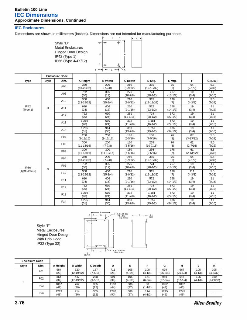
Bulletin 100 LineIEC Dimensions
3-76
Approximate Dimensions, Continued
IEC EnclosuresDimensions are shown in millimeters (inches). Dimensions are not intended for manufacturing purposes.
Type
Enclosure Code
A Height B Width C Depth D Mtg. E Mtg. F G (Dia.)Style Dim.
IP42(Type 1) D
A04 350(13-25/32)
200(7-7/8)
210(8-9/32)
315(12-13/32)
76(3)
64(2-1/2)
5.5(7/32)
A06 762(30)
305(12)
276(10-7/8)
724(28-1/2)
267(10-1/2)
19(3/4)
11(7/16)
A10 350(13-25/32)
400(15-3/4)
210(8-9/32)
315(12-13/32)
178(7)
111(4-3/8)
5.5(7/32)
A11 610(24)
406(16)
230(9-1/16)
572(22-1/2)
368(14-1/2)
19(3/4)
11(7/16)
A12 762(30)
610(24)
281(11-1/16)
724(28-1/2)
572(22-1/2)
19(3/4)
11(7/16)
A13 1,219(48)
610(24)
302(11-7/8)
1,181(46-1/2)
572(22-1/2)
19(3/4)
11(7/16)
A14 1,295(51)
914(36)
353(13-7/8)
1,257(49-1/2)
876(34-1/2)
19(3/4)
11(7/16)
IP66(Type 3/4/12) D
F08 250(9-13/16)
250(9-13/16)
160(6-5/16)
186(7-5/16)
76(3)
87(3-13/32)
5.5(7/32)
F03 300(11-13/16)
200(7-7/8)
160(6-5/16)
265(10-7/16)
76(3)
62(2-7/16)
5.5(7/32)
F09 300(11-13/16)
300(11-13/16)
160(6-5/16)
236(9-5/16)
178(7)
61(2-13/32)
5.5(7/32)
F04 350(13-25/32)
200(7-7/8)
210(8-9/32)
315(12-13/32)
76(3)
64(2-1/2)
5.5(7/32)
F06 762(30)
305(12)
276(10-7/8)
724(28-1/2)
267(10-1/2)
19(3/4)
11(7/16)
F10 350(13-25/32)
400(15-3/4)
210(8-9/32)
315(12-13/32)
178(7)
111(4-3/8)
5.5(7/32)
F11 610(24)
406(16)
230(9-1/16)
572(22-1/2)
368(14-1/2)
19(3/4)
11(7/16)
F12 762(30)
610(24)
281(11-1/16)
724(28-1/2)
572(22-1/2)
19(3/4)
11(7/16)
F13 1,219(48)
610(24)
302(11-7/8)
1,181(46-1/2)
572(22-1/2)
19(3/4)
11(7/16)
F14 1,295(51)
914(36)
353(13-7/8)
1,257(49-1/2)
876(34-1/2)
19(3/4)
11(7/16)
Enclosure Code
A Height B Width C Depth D E F G H J KStyle Dim.
F
F01 584(23)
320(12-19/32)
187(7-5/16)
711(28)
105(4-1/8)
108(4-1/4)
679(26-3/4)
667(26-1/4)
105(4-1/8)
105(4-5/32)
F02 864(34)
447(17-19/32)
238(9-5/16)
991(39)
105(4-1/8)
171(6-3/4)
959(37-3/4)
946(37-1/4)
105(4-1/8)
169(6-21/32)
F03 1067(42)
762(30)
305(12)
1118(44)
686(27)
38(1-1/2)
1092(43)
1092(43) – –
F04 1219(48)
914(36)
305(12)
1270(50)
686(27)
114(4-1/2)
1245(49)
1245(49) – –
D
F G
B
A
E
C
Style “D”Metal EnclosuresHinged Door DesignIP42 (Type 1)IP66 (Type 4/4X/12)
JK
B
HD
A
EFG
6(15/64)
C 7.1(.28)
4 – 5.5 (.22) Dia.7.1 (.28) Mtg. Holes
4 – 5.5 (.218) Dia.Mtg. Holes
Style “F”Metal EnclosuresHinged Door DesignWith Drip HoodIP32 (Type 32)
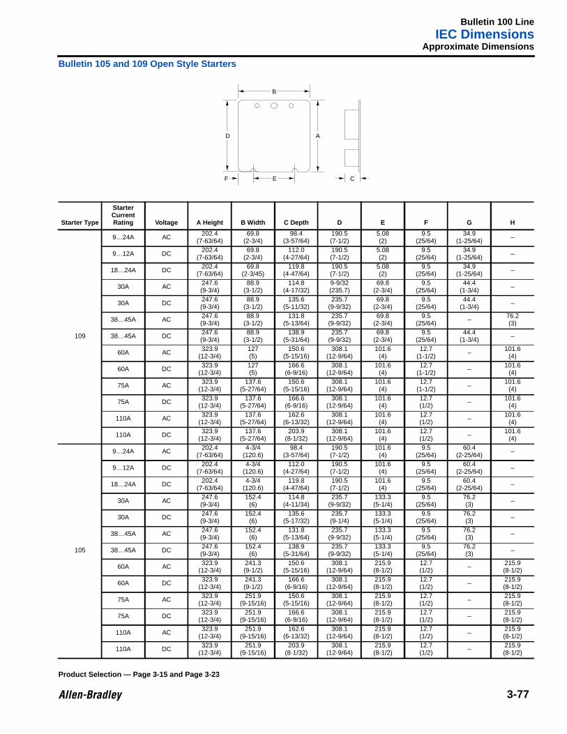
Bulletin 100 LineIEC Dimensions
3-77
Approximate Dimensions
Bulletin 105 and 109 Open Style Starters
Starter Type
StarterCurrentRating Voltage A Height B Width C Depth D E F G H
109
9…24A AC 202.4(7-63/64)
69.8(2-3/4)
98.4(3-57/64)
190.5(7-1/2)
5.08(2)
9.5(25/64)
34.9(1-25/64) –
9…12A DC 202.4(7-63/64)
69.8(2-3/4)
112.0(4-27/64)
190.5(7-1/2)
5.08(2)
9.5(25/64)
34.9(1-25/64) –
18…24A DC 202.4(7-63/64)
69.8(2-3/45)
119.8(4-47/64)
190.5(7-1/2)
5.08(2)
9.5(25/64)
34.9(1-25/64) –
30A AC 247.6(9-3/4)
88.9(3-1/2)
114.8(4-17/32)
9-9/32(235.7)
69.8(2-3/4)
9.5(25/64)
44.4(1-3/4) –
30A DC 247.6(9-3/4)
88.9(3-1/2)
135.6(5-11/32)
235.7(9-9/32)
69.8(2-3/4)
9.5(25/64)
44.4(1-3/4) –
38…45A AC 247.6(9-3/4)
88.9(3-1/2)
131.8(5-13/64)
235.7(9-9/32)
69.8(2-3/4)
9.5(25/64) – 76.2
(3)
38…45A DC 247.6(9-3/4)
88.9(3-1/2)
138.9(5-31/64)
235.7(9-9/32)
69.8(2-3/4)
9.5(25/64)
44.4(1-3/4) –
60A AC 323.9(12-3/4)
127(5)
150.6(5-15/16)
308.1(12-9/64)
101.6(4)
12.7(1-1/2) – 101.6
(4)
60A DC 323.9(12-3/4)
127(5)
166.6(6-9/16)
308.1(12-9/64)
101.6(4)
12.7(1-1/2) – 101.6
(4)
75A AC 323.9(12-3/4)
137.6(5-27/64)
150.6(5-15/16)
308.1(12-9/64)
101.6(4)
12.7(1-1/2) – 101.6
(4)
75A DC 323.9(12-3/4)
137.6(5-27/64)
166.6(6-9/16)
308.1(12-9/64)
101.6(4)
12.7(1/2) – 101.6
(4)
110A AC 323.9(12-3/4)
137.6(5-27/64)
162.6(6-13/32)
308.1(12-9/64)
101.6(4)
12.7(1/2) – 101.6
(4)
110A DC 323.9(12-3/4)
137.6(5-27/64)
203.9(8-1/32)
308.1(12-9/64)
101.6(4)
12.7(1/2) – 101.6
(4)
105
9…24A AC 202.4(7-63/64)
4-3/4(120.6)
98.4(3-57/64)
190.5(7-1/2)
101.6(4)
9.5(25/64)
60.4(2-25/64) –
9…12A DC 202.4(7-63/64)
4-3/4(120.6)
112.0(4-27/64)
190.5(7-1/2)
101.6(4)
9.5(25/64)
60.4(2-25/64) –
18…24A DC 202.4(7-63/64)
4-3/4(120.6)
119.8(4-47/64)
190.5(7-1/2)
101.6(4)
9.5(25/64)
60.4(2-25/64) –
30A AC 247.6(9-3/4)
152.4(6)
114.8(4-11/34)
235.7(9-9/32)
133.3(5-1/4)
9.5(25/64)
76.2(3) –
30A DC 247.6(9-3/4)
152.4(6)
135.6(5-17/32)
235.7(9-1/4)
133.3(5-1/4)
9.5(25/64)
76.2(3) –
38…45A AC 247.6(9-3/4)
152.4(6)
131.8(5-13/64)
235.7(9-9/32)
133.3(5-1/4)
9.5(25/64)
76.2(3) –
38…45A DC 247.6(9-3/4)
152.4(6)
138.9(5-31/64)
235.7(9-9/32)
133.3(5-1/4)
9.5(25/64)
76.2(3) –
60A AC 323.9(12-3/4)
241.3(9-1/2)
150.6(5-15/16)
308.1(12-9/64)
215.9(8-1/2)
12.7(1/2) – 215.9
(8-1/2)
60A DC 323.9(12-3/4)
241.3(9-1/2)
166.6(6-9/16)
308.1(12-9/64)
215.9(8-1/2)
12.7(1/2) – 215.9
(8-1/2)
75A AC 323.9(12-3/4)
251.9(9-15/16)
150.6(5-15/16)
308.1(12-9/64)
215.9(8-1/2)
12.7(1/2) – 215.9
(8-1/2)
75A DC 323.9(12-3/4)
251.9(9-15/16)
166.6(6-9/16)
308.1(12-9/64)
215.9(8-1/2)
12.7(1/2) – 215.9
(8-1/2)
110A AC 323.9(12-3/4)
251.9(9-15/16)
162.6(6-13/32)
308.1(12-9/64)
215.9(8-1/2)
12.7(1/2) – 215.9
(8-1/2)
110A DC 323.9(12-3/4)
251.9(9-15/16)
203.9(8-1/32)
308.1(12-9/64)
215.9(8-1/2)
12.7(1/2) – 215.9
(8-1/2)
D
F E C
B
A
Product Selection — Page 3-15 and Page 3-23
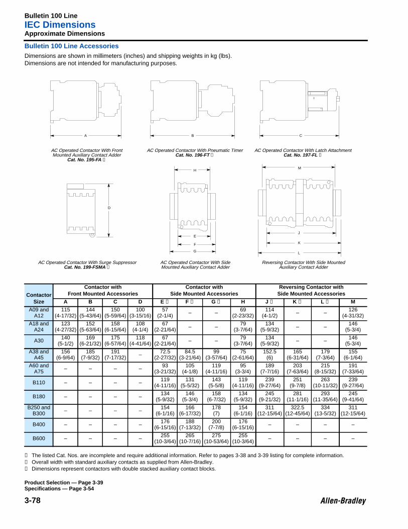
Bulletin 100 LineIEC Dimensions
3-78
Approximate Dimensions
Bulletin 100 Line AccessoriesDimensions are shown in millimeters (inches) and shipping weights in kg (lbs).Dimensions are not intended for manufacturing purposes.
➊ The listed Cat. Nos. are incomplete and require additional information. Refer to pages 3-38 and 3-39 listing for complete information.➋ Overall width with standard auxiliary contacts as supplied from Allen-Bradley.➌ Dimensions represent contactors with double stacked auxiliary contact blocks.
ContactorSize
Contactor withFront Mounted Accessories
Contactor withSide Mounted Accessories
Reversing Contactor withSide Mounted Accessories
A B C D E ➋ F ➌ G ➌ H J ➋ K ➌ L ➌ MA09 and
A12115
(4-17/32)144
(5-43/64)150
(5-59/64)100
(3-15/16)57
(2-1/4) – – 69(2-23/32)
114(4-1/2) – – 126
(4-31/32)
A18 andA24
123(4-27/32)
152(5-63/64)
158(6-15/64)
108(4-1/4)
67(2-21/64) – – 79
(3-7/64)134
(5-9/32) – – 146(5-3/4)
A30 140(5-1/2)
169(6-21/32)
175(6-57/64)
118(4-41/64)
67(2-21/64) – – 79
(3-7/64)134
(5-9/32) – – 146(5-3/4)
A38 andA45
156(6-9/64)
185(7-9/32)
191(7-17/32) – 72.5
(2-27/32)84.5
(3-21/64)99
(3-57/64)75
(2-61/64)152.5
(6)165
(6-31/64)179
(7-3/64)155
(6-1/64)
A60 andA75 – – – – 93
(3-21/32)105
(4-1/8)119
(4-11/16)95
(3-3/4)189
(7-7/16)203
(7-63/64)215
(8-15/32)191
(7-33/64)
B110 – – – – 119(4-11/16)
131(5-5/32)
143(5-5/8)
119(4-11/16)
239(9-27/64)
251(9-7/8)
263(10-11/32)
239(9-27/64)
B180 – – – – 134(5-9/32)
146(5-3/4)
158(6-7/32)
134(5-9/32)
245(9-21/32)
281(11-1/16)
293(11-35/64)
245(9-41/64)
B250 andB300 – – – – 154
(6-1/16)166
(6-17/32)178(7)
154(6-1/16)
311(12-15/64)
322.5(12-45/64)
334(13-5/32)
311(12-15/64)
B400 – – – – 176(6-15/16)
188(7-13/32)
200(7-7/8)
176(6-15/16) – – – –
B600 – – – – 255(10-3/64)
265(10-7/16)
275(10-53/64)
255(10-3/64) – – – –
A B C
D
E
F
G
HM
J
K
L
AC Operated Contactor With FrontMounted Auxiliary Contact Adder
Cat. No. 195-FA ➊
AC Operated Contactor With Pneumatic TimerCat. No. 196-FT ➊
AC Operated Contactor With Latch AttachmentCat. No. 197-FL ➊
AC Operated Contactor With Surge SuppressorCat. No. 199-FSMA ➊
AC Operated Contactor With SideMounted Auxiliary Contact Adder
Reversing Contactor With Side MountedAuxiliary Contact Adder
Product Selection — Page 3-39Specifications — Page 3-54
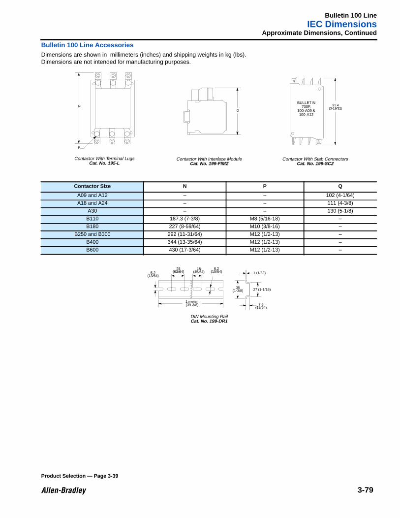
Bulletin 100 LineIEC Dimensions
3-79
Approximate Dimensions, Continued
Bulletin 100 Line AccessoriesDimensions are shown in millimeters (inches) and shipping weights in kg (lbs).Dimensions are not intended for manufacturing purposes.
Contactor Size N P Q
A09 and A12 – – 102 (4-1/64)
A18 and A24 – – 111 (4-3/8)
A30 – – 130 (5-1/8)
B110 187.3 (7-3/8) M8 (5/16-18) –
B180 227 (8-59/64) M10 (3/8-16) –
B250 and B300 292 (11-31/64) M12 (1/2-13) –
B400 344 (13-35/64) M12 (1/2-13) –
B600 430 (17-3/64) M12 (1/2-13) –
N
P
Q
BULLETIN700F,
100-A09 &100-A12
91.4(3-19/32)
Contactor With Terminal LugsCat. No. 195-L
Contactor With Interface ModuleCat. No. 199-FIMZ
Contactor With Stab ConnectorsCat. No. 199-SC2
5.2(13/64)
25(63/64)
18(45/64)
6.2(15/64)
(39-3/8)
1 (1/32)
35(1-3/8) 27 (1-1/16)
7.5(19/64)
1 meter
DIN Mounting RailCat. No. 199-DR1
Product Selection — Page 3-39
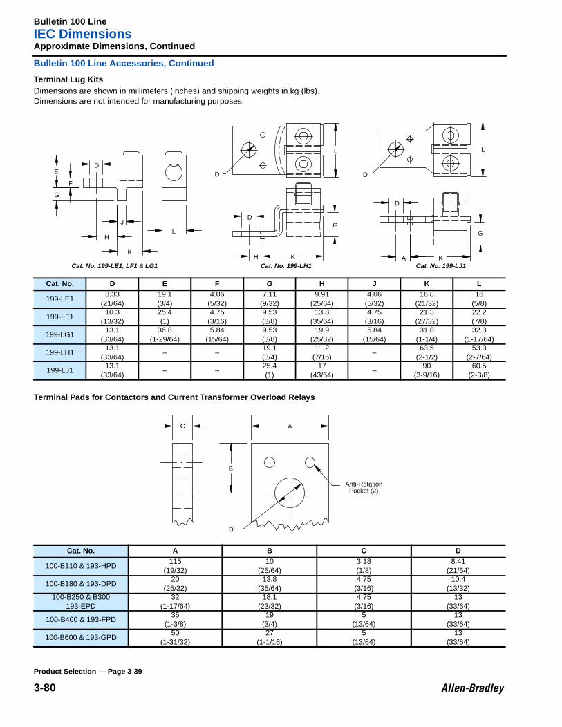
Bulletin 100 LineIEC Dimensions
3-80
Approximate Dimensions, Continued
Bulletin 100 Line Accessories, Continued
Terminal Lug KitsDimensions are shown in millimeters (inches) and shipping weights in kg (lbs).Dimensions are not intended for manufacturing purposes.
Terminal Pads for Contactors and Current Transformer Overload Relays
Cat. No. D E F G H J K L
199-LE18.33
(21/64)19.1(3/4)
4.06(5/32)
7.11(9/32)
9.91(25/64)
4.06(5/32)
16.8(21/32)
16(5/8)
199-LF110.3
(13/32)25.4(1)
4.75(3/16)
9.53(3/8)
13.8(35/64)
4.75(3/16)
21.3(27/32)
22.2(7/8)
199-LG113.1
(33/64)36.8
(1-29/64)5.84
(15/64)9.53(3/8)
19.9(25/32)
5.84(15/64)
31.8(1-1/4)
32.3(1-17/64)
199-LH113.1
(33/64)– –
19.1(3/4)
11.2(7/16)
–63.5
(2-1/2)53.3
(2-7/64)
199-LJ113.1
(33/64)– –
25.4(1)
17(43/64)
–90
(3-9/16)60.5
(2-3/8)
Cat. No. A B C D
100-B110 & 193-HPD115
(19/32)10
(25/64)3.18(1/8)
8.41(21/64)
100-B180 & 193-DPD20
(25/32)13.8
(35/64)4.75
(3/16)10.4
(13/32)100-B250 & B300
193-EPD32
(1-17/64)18.1
(23/32)4.75
(3/16)13
(33/64)
100-B400 & 193-FPD35
(1-3/8)19
(3/4)5
(13/64)13
(33/64)
100-B600 & 193-GPD50
(1-31/32)27
(1-1/16)5
(13/64)13
(33/64)
D
D
L
G
KA
G
KH
D
D
L
L
K
J
H
F
DE
G
Cat. No. 199-LE1 , LF1 & LG1 Cat. No. 199-LH1 Cat. No. 199-LJ1
C
B
D
A
Anti-RotationPocket (2)
Product Selection — Page 3-39
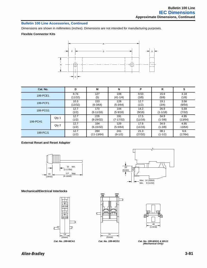
Bulletin 100 LineIEC Dimensions
3-81
Approximate Dimensions, Continued
Bulletin 100 Line Accessories, ContinuedDimensions are shown in millimeters (inches). Dimensions are not intended for manufacturing purposes.
Flexible Connector Kits
External Reset and Reset Adapter
Mechanical/Electrical Interlocks
Cat. No. D M N P R S
199-PCE18.74
(11/32)127(5)
108(41-1/4)
9.53(3/8)
15.9(5/8)
3.18(1/8)
199-PCF110.3
(13/32)153
(6-3/64)128
(5-3/64)12.7(1/2)
19.1(3/4)
3.56(9/54)
199-PCG112.7(1/2)
170(6-11/16)
144(5-9/16)
14.2(9/16)
26.9(1-1/16)
5.59(7/32)
199-PCH1Qty 1
12.7(1/2)
226(8-29/32)
191(7-17/32)
17.5(11/16)
34.9(1-3/8)
4.95(13/64)
Qty 212.7(1/2)
164(6-15/32)
129(5-5/64)
17.5(11/16)
34.9(1-3/8)
4.9513/64)
199-PCJ112.7(1/2)
284(11-13/64)
241(9-1/2)
21.3(27/32)
38.1(1-1/2)
6.6(17/64)
M
N SP
R
D
20(51/64)
Max. 14 (35/64)Min. 9 (11/32)
32(1-17/64)
15(19/32)
Min.
117(4-19/64)
Max.
21(53/64)
40(1-9/16)
13(33/64)
Cat. No. 199-MCD1 Cat. No. 199-MXH1 & MXJ1(Mechanical Only)
Cat. No. 199-MCA1
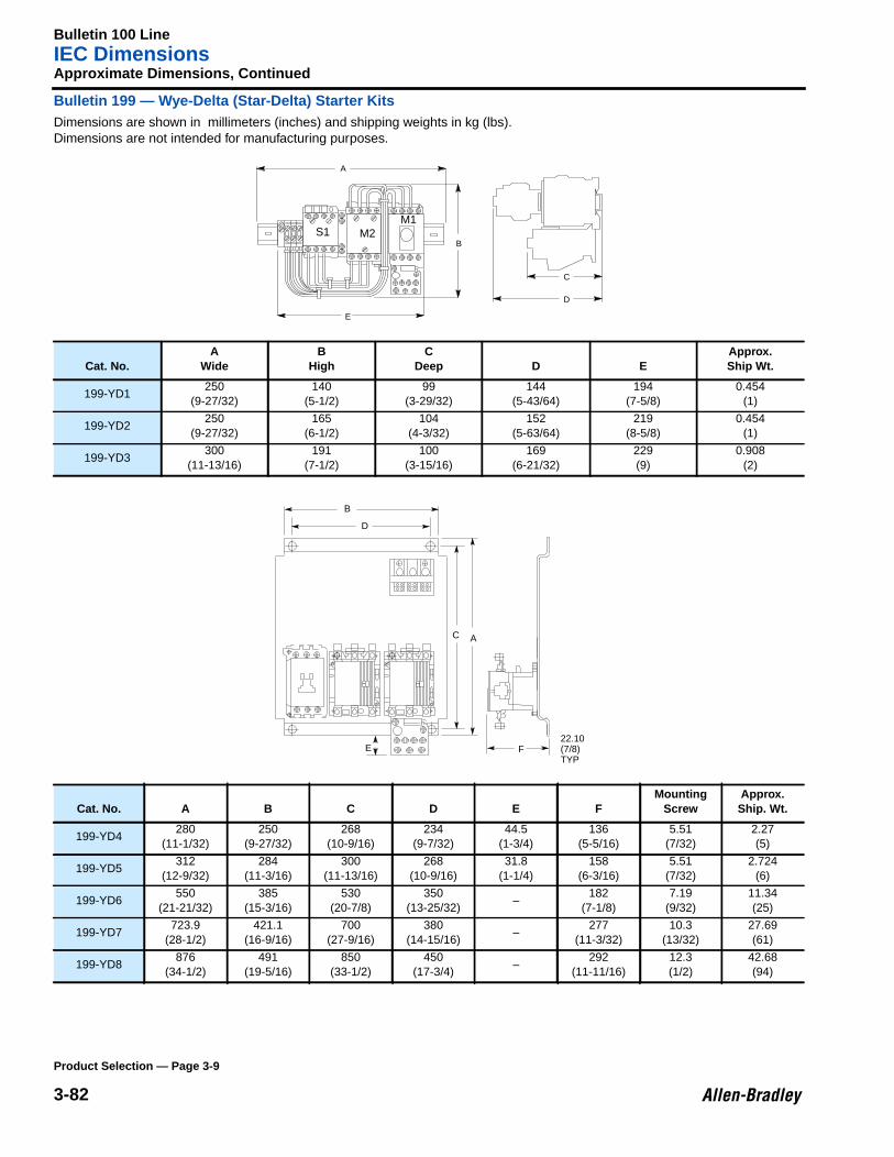
Bulletin 100 LineIEC Dimensions
3-82
Approximate Dimensions, Continued
Bulletin 199 — Wye-Delta (Star-Delta) Starter KitsDimensions are shown in millimeters (inches) and shipping weights in kg (lbs).Dimensions are not intended for manufacturing purposes.
Cat. No.A
WideB
HighC
Deep D EApprox.Ship Wt.
199-YD1250
(9-27/32)140
(5-1/2)99
(3-29/32)144
(5-43/64)194
(7-5/8)0.454
(1)
199-YD2250
(9-27/32)165
(6-1/2)104
(4-3/32)152
(5-63/64)219
(8-5/8)0.454
(1)
199-YD3300
(11-13/16)191
(7-1/2)100
(3-15/16)169
(6-21/32)229(9)
0.908(2)
Cat. No. A B C D E FMounting
ScrewApprox.Ship. Wt.
199-YD4280
(11-1/32)250
(9-27/32)268
(10-9/16)234
(9-7/32)44.5
(1-3/4)136
(5-5/16)5.51
(7/32)2.27(5)
199-YD5312
(12-9/32)284
(11-3/16)300
(11-13/16)268
(10-9/16)31.8
(1-1/4)158
(6-3/16)5.51
(7/32)2.724
(6)
199-YD6550
(21-21/32)385
(15-3/16)530
(20-7/8)350
(13-25/32)–
182(7-1/8)
7.19(9/32)
11.34(25)
199-YD7723.9
(28-1/2)421.1
(16-9/16)700
(27-9/16)380
(14-15/16)–
277(11-3/32)
10.3(13/32)
27.69(61)
199-YD8876
(34-1/2)491
(19-5/16)850
(33-1/2)450
(17-3/4)–
292(11-11/16)
12.3(1/2)
42.68(94)
C
D
A
B
E
S1 M2M1
A
D
B
C
22.10(7/8)TYP
E F
Product Selection — Page 3-9