building scalable cisco internetworks - mikdocstore.mik.ua/cisco/pdf/routing/bsciv-isis.pdf ·...
TRANSCRIPT

BSCI
Building Scalable Cisco Internetworks Version 1.2
Student Guide
Text Part Number: Review Copy
Click Here to Post Review Comments

The products and specifications, configurations, and other technical information regarding the products in this manual are subject to change without notice. All statements, technical information, and recommendations in this manual are believed to be accurate but are presented without warranty of any kind, express or implied. You must take full responsibility for their application of any products specified in this manual. LICENSE PLEASE READ THESE TERMS AND CONDITIONS CAREFULLY BEFORE USING THE MANUAL, DOCUMENTATION, AND/OR SOFTWARE (“MATERIALS”). BY USING THE MATERIALS YOU AGREE TO BE BOUND BY THE TERMS AND CONDITIONS OF THIS LICENSE. IF YOU DO NOT AGREE WITH THE TERMS OF THIS LICENSE, PROMPTLY RETURN THE UNUSED MATERIALS (WITH PROOF OF PAYMENT) TO THE PLACE OF PURCHASE FOR A FULL REFUND. Cisco Systems, Inc. (“Cisco”) and its suppliers grant to you (“You”) a nonexclusive and nontransferable license to use the Cisco Materials solely for Your own personal use. If the Materials include Cisco software (“Software”), Cisco grants to You a nonexclusive and nontransferable license to use the Software in object code form solely on a single central processing unit owned or leased by You or otherwise embedded in equipment provided by Cisco. You may make one (1) archival copy of the Software provided You affix to such copy all copyright, confidentiality, and proprietary notices that appear on the original. EXCEPT AS EXPRESSLY AUTHORIZED ABOVE, YOU SHALL NOT: COPY, IN WHOLE OR IN PART, MATERIALS; MODIFY THE SOFTWARE; REVERSE COMPILE OR REVERSE ASSEMBLE ALL OR ANY PORTION OF THE SOFTWARE; OR RENT, LEASE, DISTRIBUTE, SELL, OR CREATE DERIVATIVE WORKS OF THE MATERIALS. You agree that aspects of the licensed Materials, including the specific design and structure of individual programs, constitute trade secrets and/or copyrighted material of Cisco. You agree not to disclose, provide, or otherwise make available such trade secrets or copyrighted material in any form to any third party without the prior written consent of Cisco. You agree to implement reasonable security measures to protect such trade secrets and copyrighted Material. Title to the Materials shall remain solely with Cisco. This License is effective until terminated. You may terminate this License at any time by destroying all copies of the Materials. This License will terminate immediately without notice from Cisco if You fail to comply with any provision of this License. Upon termination, You must destroy all copies of the Materials. Software, including technical data, is subject to U.S. export control laws, including the U.S. Export Administration Act and its associated regulations, and may be subject to export or import regulations in other countries. You agree to comply strictly with all such regulations and acknowledge that it has the responsibility to obtain licenses to export, re-export, or import Software. This License shall be governed by and construed in accordance with the laws of the State of California, United States of America, as if performed wholly within the state and without giving effect to the principles of conflict of law. If any portion hereof is found to be void or unenforceable, the remaining provisions of this License shall remain in full force and effect. This License constitutes the entire License between the parties with respect to the use of the Materials Restricted Rights - Cisco’s software is provided to non-DOD agencies with RESTRICTED RIGHTS and its supporting documentation is provided with LIMITED RIGHTS. Use, duplication, or disclosure by the U.S. Government is subject to the restrictions as set forth in subparagraph “C” of the Commercial Computer Software - Restricted Rights clause at FAR 52.227-19. In the event the sale is to a DOD agency, the U.S. Government’s rights in software, supporting documentation, and technical data are governed by the restrictions in the Technical Data Commercial Items clause at DFARS 252.227-7015 and DFARS 227.7202. DISCLAIMER OF WARRANTY. ALL MATERIALS ARE PROVIDED “AS IS” WITH ALL FAULTS. CISCO AND ITS SUPPLIERS DISCLAIM ALL WARRANTIES, EXPRESSED OR IMPLIED, INCLUDING, WITHOUT LIMITATION, THOSE OF MERCHANTABILITY, FITNESS FOR A PARTICULAR PURPOSE AND NONINFRINGEMENT OR ARISING FROM A COURSE OF DEALING, USAGE, OR TRADE PRACTICE. IN NO EVENT SHALL CISCO OR ITS SUPPLIERS BE LIABLE FOR ANY INDIRECT, SPECIAL, CONSEQUENTIAL, OR INCIDENTAL DAMAGES, INCLUDING, WITHOUT LIMITATION, LOST PROFITS OR LOSS OR DAMAGE TO DATA ARISING OUT OF THE USE OR INABILITY TO USE THIS MANUAL, EVEN IF CISCO OR ITS SUPPLIERS HAVE BEEN ADVISED OF THE POSSIBILITY OF SUCH DAMAGES. In no event shall Cisco’s or its suppliers’ liability to You, whether in contract, tort (including negligence), or otherwise, exceed the price paid by You. The foregoing limitations shall apply even if the above-stated warranty fails of its essential purpose. The following information is for FCC compliance of Class A devices: This equipment has been tested and found to comply with the limits for a Class A digital device, pursuant to part 15 of the FCC rules. These limits are designed to provide reasonable protection against harmful interference when the equipment is operated in a commercial environment. This equipment generates, uses, and can radiate radio-frequency energy and, if not installed and used in accordance with the instruction manual, may

cause harmful interference to radio communications. Operation of this equipment in a residential area is likely to cause harmful interference, in which case users will be required to correct the interference at their own expense. The following information is for FCC compliance of Class B devices: The equipment described in this manual generates and may radiate radio-frequency energy. If it is not installed in accordance with Cisco’s installation instructions, it may cause interference with radio and television reception. This equipment has been tested and found to comply with the limits for a Class B digital device in accordance with the specifications in part 15 of the FCC rules. These specifications are designed to provide reasonable protection against such interference in a residential installation. However, there is no guarantee that interference will not occur in a particular installation. You can determine whether your equipment is causing interference by turning it off. If the interference stops, it was probably caused by the Cisco equipment or one of its peripheral devices. If the equipment causes interference to radio or television reception, try to correct the interference by using one or more of the following measures: • Turn the television or radio antenna until the interference stops. • Move the equipment to one side or the other of the television or radio . • Move the equipment farther away from the television or radio. • Plug the equipment into an outlet that is on a different circuit from the television or radio. (That is, make certain the equipment and the television or radio are on circuits controlled by different circuit breakers or fuses.) Modifications to this product not authorized by Cisco Systems, Inc. could void the FCC approval and negate your authority to operate the product. The following third-party software may be included with your product and will be subject to the software license agreement: CiscoWorks software and documentation are based in part on HP OpenView under license from the Hewlett-Packard Company. HP OpenView is a trademark of the Hewlett-Packard Company. Copyright © 1992, 1993 Hewlett-Packard Company. The Cisco implementation of TCP header compression is an adaptation of a program developed by the University of California, Berkeley (UCB) as part of UCB’s public domain version of the UNIX operating system. All rights reserved. Copyright © 1981, Regents of the University of California. Network Time Protocol (NTP). Copyright © 1992, David L. Mills. The University of Delaware makes no representations about the suitability of this software for any purpose.
Point-to-Point Protocol. Copyright © 1989, Carnegie-Mellon University. All rights reserved. The name of the University may not be used to endorse or promote products derived from this software without specific prior written permission.
The Cisco implementation of TN3270 is an adaptation of the TN3270, curses, and termcap programs developed by the University of California, Berkeley (UCB) as part of UCB’s public domain version of the UNIX operating system. All rights reserved. Copyright © 1981-1988, Regents of the University of California.
Cisco incorporates Fastmac and TrueView software and the RingRunner chip in some Token Ring products. Fastmac software is licensed to Cisco by Madge Networks Limited, and the RingRunner chip is licensed to Cisco by Madge NV. Fastmac, RingRunner, and TrueView are trademarks and in some jurisdictions registered trademarks of Madge Networks Limited. Copyright © 1995, Madge Networks Limited. All rights reserved.
XRemote is a trademark of Network Computing Devices, Inc. Copyright © 1989, Network Computing Devices, Inc., Mountain View, California. NCD makes no representations about the suitability of this software for any purpose.
The X Window System is a trademark of the X Consortium, Cambridge, Massachusetts. All rights reserved.
Cisco Systems has more than 200 offices in the following countries and regions. Addresses, phone numbers, and fax numbers are listed on the Cisco Web site at www.cisco.com/go/offices.
Argentina Australia Austria Belgium Brazil Bulgaria Canada Chile China PRC Colombia Costa Rica Croatia Czech Republic Denmark Dubai, UAE Finland France Germany Greece Hong Kong SAR Hungary India Indonesia Ireland Israel Italy Japan Korea Luxembourg Malaysia Mexico The Netherlands New Zealand Norway Peru Philippines Poland Portugal Puerto Rico Romania Russia Saudi Arabia Scotland Singapore Slovakia Slovenia South Africa Spain Sweden Switzerland Taiwan Thailand Turkey Ukraine United Kingdom United States Venezuela Vietnam Zimbabwe
Copyright 2001, Cisco Systems, Inc. All rights reserved. AccessPath, AtmDirector, Browse with Me, CCDA, CCDE, CCDP, CCIE, CCNA, CCNP, CCSI, CD-PAC, CiscoLink, the Cisco NetWorks logo, the Cisco Powered Network logo, Cisco Systems Networking Academy, Fast
Step, Follow Me Browsing, FormShare, FrameShare, GigaStack, IGX, Internet Quotient, IP/VC, iQ
Breakthrough, iQ Expertise, iQ FastTrack, the iQ logo, iQ Net Readiness Scorecard, MGX, the Networkers logo, Packet, RateMUX, ScriptBuilder, ScriptShare, SlideCast, SMARTnet, TransPath, Unity, Voice LAN, Wavelength Router, and WebViewer are trademarks of Cisco Systems, Inc.; Changing the Way We Work, Live, Play, and Learn, Discover All That’s Possible, and Empowering the Internet Generation, are service marks of Cisco Systems, Inc.; and Aironet, ASIST, BPX, Catalyst, Cisco, the Cisco Certified Internetwork Expert Logo, Cisco IOS, the Cisco IOS logo, Cisco Systems, Cisco Systems Capital, the Cisco Systems logo, Enterprise/Solver, EtherChannel, EtherSwitch, FastHub, FastSwitch, IOS, IP/TV, LightStream, MICA, Network Registrar, PIX, Post -Routing, Pre-Routing, Registrar, StrataView Plus, Stratm, SwitchProbe, TeleRouter, and VCO are registered trademarks of Cisco Systems, Inc. and/or its affiliates in the U.S. and certain other countries.
All other brands, names, or trademarks mentioned in this document or Web site are the property of their respective owners. The use of the word partner does not imply a partnership relationship between Cisco and any other company. (0104R)
This Document is strictly controlled through the Cisco Learning Partner license agreement. Accordingly, do not copy, print or distribute this preliminary document.
Building Scalable Cisco Internetworks, Revision 1.2: Student Guide
Copyright 2001, Cisco Systems, Inc. All rights reserved. Printed in USA.

Copyright 2001, Cisco Systems, Inc. Building Scalable Cisco Internetworking v
Table of Contents
INTRODUCTION 1-1
Overview 1-1 Course Objectives 1-2 Course Objectives (cont.) 1-3 Course Topics 1-4 Prerequisites 1-5 Participant Role 1-8 General Administration 1-10 Sources of Information 1-11 Course Syllabus 1-12 Graphic Symbols 1-14
ROUTING PRINCIPLES 2-1
Overview 2-1 Objectives 2-2 Classful Routing Protocol Overview 2-3 Classless Routing Overview 2-6 Distance Vector Operation 2-9 Link-State Operation 2-10 Written Exercise: Comparing Routing Protocols 2-29
Objective 2-29 Task 2-29 Completion Criteria 2-30
Summary 2-31 Review Questions 2-32
EXTENDING IP ADDRESSES 3-1
Overview 3-1 Objectives 3-2 IP Addressing Issues 3-3 IP Addressing Solutions 3-4 Hierarchical Addressing 3-9 VLSMs 3-11 Written Exercise 1: Calculating VLSMs 3-14
Objective 3-14 Task 3-14 Completion Criteria 3-14
Route Summarization 3-15 Written Exercise 2: Using Route Summarization 3-25
Objective 3-25
Click Here to Post Review Comments

vi Building Scalable Cisco Internetworking Copyright 2001, Cisco Systems, Inc.
Task 1 3-25 Task 2 3-26 Completion Criteria 3-26
Classless Interdomain Routing 3-27 Summary 3-29 Review Questions 3-30
CONFIGURING EIGRP 4-1
Overview 4-1 Outline 4-1
Objectives 4-2 EIGRP Overview 4-4 EIGRP Operation 4-13 Written Exercise: EIGRP Overview 4-34
Objective 4-34 Task 4-34 Completion Criteria 4-34
Configuring EIGRP 4-35 Using EIGRP in Scalable Internetworks 4-54 Verifying EIGRP Operation 4-69 Summary 4-71 Review Questions 4-73
CONFIGURING OSPF IN A SINGLE AREA 5-1
Overview 5-1 Objectives 5-2 Objectives (cont.) 5-3 OSPF Overview 5-4 OSPF Terminology 5-7 OSPF Operation 5-9
OSPF Operation in a Broadcast Multiaccess Topology 5-10 OSPF Operation in a Point-to-Point Topology 5-21 OSPF Operation in an NBMA Topology 5-22
Written Exercise: OSPF Operation 5-34 Objective 5-34 Task 5-34 Completion Criteria 5-35
Configuring OSPF in a Single Area 5-36 Verifying OSPF Operation 5-48 Summary 5-57 Summary (cont.) 5-58 Review Questions 5-59
INTERCONNECTING MULTIPLE OSPF AREAS 6-1
Overview 6-1 Objectives 6-2 Objectives (cont.) 6-3

Copyright 2001, Cisco Systems, Inc. Building Scalable Cisco Internetworking vii
Creating Multiple OSPF Areas 6-4 Routing Table Results with Different Areas 6-14
OSPF Operation Across Multiple Areas 6-15 Virtual Links Overview 6-18 Written Exercise: OSPF Operation Across Multiple Areas 6-20
Objective 6-20 Task 6-20 Completion Criteria 6-21
Using and Configuring OSPF Multiarea Components 6-22 Verifying OSPF Operation 6-40 Summary 6-42 Summary (cont.) 6-43 Review Questions 6-44
CONFIGURING IS-IS PROTOCOL 7-1
Overview 7-1 Objectives 7-2 Introduction to OSI Protocols and IS-IS Routing 7-3 Operation of IS-IS 7-28 IP and OSI Routing with Integrated IS-IS 7-53 Basic Integrated IS-IS Router Configuration 7-69 Modeling WAN Networks in Integrated IS-IS 7-83 Summary 7-97 Review Questions 7-97
OPTIMIZING ROUTING UPDATE OPERATION 8-1
Overview 8-1 Objectives 8-2 Objectives (cont.) 8-3 Redistribution Between Multiple Routing Protocols 8-4 Configuring Redistribution 8-12 Controlling Routing Update Traffic 8-27 Verifying Redistribution Operation 8-41 Written Exercise: Redistribution and Controlling Routing Update Traffic 8-43
Objectives 8-43 Task 8-43 Completion Criteria 8-44
Policy-Based Routing Using Route Maps 8-45 Verifying Policy-Based Routing 8-58 Summary 8-62 Summary (cont.) 8-63 Review Questions 8-64 Review Questions (cont.) 8-65
CONFIGURING BASIC BGP 9-1
Overview 9-1 Objectives 9-2 BGP Overview 9-4

viii Building Scalable Cisco Internetworking Copyright 2001, Cisco Systems, Inc.
When Not to Use BGP 9-10 BGP Terminology 9-14 BGP Operation 9-38 Written Exercise: BGP Terminology and Operation 9-44
Objectives 9-44 Task 9-44 Completion Criteria 9-45
Configuring BGP 9-46 Verifying BGP 9-57 Summary 9-62 Review Questions 9-64
IMPLEMENTING BGP IN SCALABLE NETWORKS 10-1
Overview 10-1 Objectives 10-2 Objectives (cont.) 10-3 Scalability Problems with IBGP 10-4 Route Reflectors 10-7 Policy Control 10-17 Written Exercise: BGP Route Reflectors and Policy Control 10-28
Objectives 10-28 Task 10-28 Completion Criteria 10-29
Multihoming 10-30 Redistribution with IGPs 10-45 Summary 10-52 Summary (cont.) 10-53 Review Questions 10-54
JOB AIDS AND SUPPLEMENTS A-1
Overview A-1 Extending IP Addresses A-2 Job Aids A-3
IP Addresses and Subnetting A-3 Decimal-to-Binary Conversion Chart A-4
Binary A-4 Supplement 1: Addressing Review A-5 Supplement 2: IP Access Lists A-16 Supplement 3: IP Features A-56 Using IP Unnumbered Interfaces A-56
Using Helper Addresses A-59 Supplement 4: EIGRP A-66 Supplement 5: OSPF A-70 Supplement 6: Route Optimization A-85 Supplement 7: BGP A-109
ROUTER PASSWORD RECOVERY B-1
Overview B-1

Copyright 2001, Cisco Systems, Inc. Building Scalable Cisco Internetworking ix
Router Password Recovery Procedure B-2
ANSWERS C-1
Overview C-1 Chapter 2 Exercises C-2
Answers to Written Exercise: Comparing Routing Protocols C-2 Answers to Review Questions C-3
Chapter 3 Exercises C-4 Answers to Written Exercise: Calculating VLSMs C-4 Answers to Written Exercises: Using Route Summarization C-5 Answers to Review Questions C-5
Chapter 4 Exercises C-6 Answers to Written Exercise: EIGRP Overview C-6 Answers to Review Questions C-7
Chapter 5 Exercises C-8 Answers to Written Exercise: OSPF Operation C-8 Answers to Review Questions C-9
Chapter 6 Exercises C-10 Answers to Written Exercise: OSPF Operation Across Multiple Areas C-10 Answers to Review Questions C-11
Chapter 7 C-13 Answers To Review Questions 13 Answers to Written Exercise: Redistribution and Controlling Routing Update Traffic C-15 Answers To Review Questions C-16
Chapter 9 Exercises C-18 Answers to Written Exercise: BGP Terminology and Operation C-18 Answers to Review Questions C-19
Chapter 10 Exercises C-21 Answers to Written Exercise: BGP Route Reflectors and Policy Control C-21 Answers to Review Questions C-22
Appendix A Exercises C-23 Answers to Extending IP Addressing Written Exercise: Calculating Subnet Masks C-23 Answers to IP Access Lists Written Exercise: IP Extended Access Lists C-24 Answers to Review Questions C-24
Laboratory Exercises Written Questions C-25 Laboratory Exercise 1: Configuring EIGRP C-25 Laboratory Exercise 2: Configuring OSPF for a Single Area C-25 Laboratory Exercise 3: Configuring OSPF for a Single Area in an NBMA Environment C-25 Laboratory Exercise 4: Configuring a Multiarea OSPF Network C-26 Laboratory Exercise 5: Configuring a Multiarea IS-IS Network C-26 Laboratory Exercise 6: Configuring Policy-Based Routing C-26 Laboratory Exercise 7: Configuring Route Redistribution between OSPF and EIGRP C-27 Laboratory Exercise 8: Configuring BGP C-27 Laboratory Exercise 9: Configuring BGP Route Reflectors and Prefix-List Filtering C-27 Laboratory Exercise 10: Configuring Multihomed BGP C-27 Laboratory Exercise 12: Super Lab Part I and Part II C-27
LABORATORY EXERCISES D-1

x Building Scalable Cisco Internetworking Copyright 2001, Cisco Systems, Inc.
Introduction D-1 Laboratory Exercise 1: Configuring EIGRP D-2
Objectives D-2 Visual Objective D-3 Command List D-3 Setup D-4 Scenario D-4 Task 1: Enabling EIGRP Within Your Pod D-6 Task 2: Enabling EIGRP Connectivity to the backbone_r1 Router D-7 Completion Criteria D-9 Student Notes D-10
Laboratory Exercise 2: Configuring OSPF for a Single Area D-11 Objectives D-11 Visual Objective D-11 Command List D-12 Setup D-12 Scenario D-12 Task 1: Enabling OSPF Within Your Pod D-13 Task 2: Enabling OSPF Connectivity to the Backbone_r1 Router D-15 Completion Criteria D-16 Student Notes D-17
Laboratory Exercise 3: Configuring OSPF for a Single Area in an NBMA Environment D-18
Objectives D-18 Visual Objective D-19 Command List D-20 Setup D-20 Scenario D-20 Task 1: Creating the Frame Relay Switch D-21 Task 2: Enabling OSPF Over an NBMA Network Using a Main Interface D-22 Task 3: Enabling OSPF Over an NBMA Network Using a Point-to-Point Subinterface D-23 Completion Criteria D-23 Student Notes D-24
Laboratory Exercise 4: Configuring a Multiarea OSPF Network D-25 Objectives D-25 Visual Objective D-26 Command List D-27 Setup D-28 Scenario D-29 Task 1: Enabling OSPF with Multiple Areas and Area Summarization D-29 Task 2: Enabling OSPF Stub Area D-31 Task 3: Enabling an OSPF Totally Stubby Area D-31 Task 4: Enabling OSPF Not-So-Stubby Area (Optional) D-32 Task 5: Enabling an OSPF Virtual Link to Support an OSPF Area not Connected to Area 0 (Optional) D-35 Completion Criteria D-37 Student Notes D-38
Laboratory Exercise 5: Configuring a Multiarea IS-IS Network D-39 Objectives D-39 Visual Objective D-40 Command List D-41
router isis D-41 router isis D-42
Setup D-42 Scenario D-42
Copyright 2001, Cisco Systems, Inc. Building Scalable Cisco Internetworking xi
Task 1: Enabling IS-IS within your pod D-42 Task 2: Enabling connectivity to the backbone_r1 router D-44 Task 3: Changing the IS-IS router type D-44 Task 4: Configure route summarization D-45 Task 5: Using IS-IS show and debug commands D-46 Completion Criteria D-48
Student Notes D-49 Laboratory Exercise 6: Configuring Policy-Based Routing D-50
Objectives D-50 Visual Objective D-50 Command List D-51 Setup D-51 Scenario D-51 Task 1: Enable IP Policy-Based Routing at pxr1 D-52 Completion Criteria D-54 Student Notes D-55
Laboratory Exercise 7: Configuring Route Redistribution Between OSPF and EIGRP D-56
Objectives D-56 Visual Objective D-56 Command List D-57 Setup D-57 Scenario D-57 Task 1: Enabling OSPF Between pxr1 (S0 and S1) and pxr2 (S0 and S1) D-58 Task 2: Enabling EIGRP Between pxr1 (S2) and pxr3 (S0) D-58 Task 3: Enabling Route Redistribution Between OSPF and EIGRP D-58 Task 4: Enabling Route Redistribution from EIGRP to OSPF with Filtering D-59 Completion Criteria D-60 Student Notes D-61
Laboratory Exercise 8: Configuring BGP D-62 Objectives D-62 Visual Objective D-63 Command List D-63 Setup D-65 Scenario D-65 Task 1: Enabling EBGP D-66 Task 2: Enabling Full-Mesh IBGP Within Your Pod (AS) D-68 Completion Criteria D-70 Student Notes D-71
Laboratory Exercise 9: Configuring BGP Route Reflectors and Prefix-List Filtering D-72
Objectives D-72 Visual Objective D-72 Command List D-73 Setup D-73 Scenario D-73 Task 1: Enabling pxr1 to be the Route Reflector D-74 Task 2: Enabling Inbound Prefix-List D-76 Completion Criteria D-76 Student Notes D-77
Laboratory Exercise 10: Configuring Multi-homed BGP D-78 Objectives D-78 Visual Objective D-79 Command List D-79

xii Building Scalable Cisco Internetworking Copyright 2001, Cisco Systems, Inc.
Setup D-80 Scenario D-80 Task 1: Enabling a Second EBGP Connection D-81 Completion Criteria D-83
Laboratory Exercise 11: Super Lab I D-85 Part I D-85 Objectives D-85 Visual Objective D-86 Command List D-86 Setup D-86 Scenario D-86 Task D-88 Completion Criteria D-88 Student Notes D-89
Laboratory Exercise 12: Super Lab II D-90
Part II D-91 Objectives D-92
Visual Objective D-92 Command List D-92 Setup D-92 Scenario D-92 Task D-94 Completion Criteria D-94 Student Notes D-95

7 1
Configuring IS-IS Protocol 2
Overview 3
This lesson provides an overview of Intermediate System-to-Intermediate System (IS-IS) 4
technology, and its structures and protocols, as well as basic configuration examples. The lesson 5
begins with Open System Interconnection (OSI) routing and then focuses on Integrated IS-IS as 6
a version that supports IP networks. Basic IS-IS and Integrated IS-IS router configuration 7
commands, examples, and some troubleshooting guidelines are presented at the end of the 8
lesson. The major part of this lesson is dedicated to an explanation of IS-IS concepts and 9
capabilities, including hierarchy and addressing of OSI-based networks. 10
Outline 11
The lesson includes these sections: 12
n Objectives 13
n Introduction to OSI Protocols and IS-IS Routing 14
n Operation of IS-IS 15
n IP and OSI Routing with Integrated IS-IS 16
n Basic Integrated IS-IS Router Configuration 17
n Modeling WAN Networks in Integrated IS-IS 18
n Summary 19
n Review Questions 20
Click Here to Post Review Comments

7-2 Building Scalable Cisco Internetworks (BSCI) v1.2 Copyright 2001, Cisco Systems, Inc.
Objectives 21
This section lists the lesson objectives. 22
Insert Slide here. n Explain basic OSI terminology and network layer protocols used in OSI 23
n Identify similarities and differences between Integrated IS-IS and OSPF 24
n Identify characteristics of an effective addressing plan for IS-IS deployment 25
n Explain how networks and interfaces are represented in IS-IS 26
n List the types of IS-IS routers and their role in IS-IS area design 27
n Describe the hierarchical structure of IS-IS areas 28
© 2001, Cisco Systems, Inc. BSCI v1.2 — 7-2
ObjectivesObjectives
Upon completing this lesson, you will be able to:• Explain basic OSI terminology and network layer
protocols used in OSI• Identify similarities and differences between
Integrated IS-IS and OSPF• Identify characteristics of an effective addressing
plan for IS-IS deployment• Explain how networks and interfaces are
represented in IS-IS• List the types of IS-IS routers and their role in IS-IS
area design• Describe the hierarchical structure of IS-IS areas

Copyright 2001, Cisco Systems, Inc. Configuring IS-IS Protocol 7-3
Objectives (cont.) 29
Insert Slide here. n Describe the concept of establishing adjacencies 30
n Describe the concepts of routing traffic transport and database synchronization 31
n Explain the basic principles of area routing 32
n Explain IS-IS nonbroadcast multiaccess (NBMA) network modeling solutions in switched 33
WAN networks 34
n Identify the steps to configure Cisco routers for proper Integrated IS-IS operation, given an 35
addressing scheme and other laboratory parameters 36
n Identify verification methods that ensure proper operation of Integrated IS-IS on Cisco 37
routers 38
© 2001, Cisco Systems, Inc. BSCI v1.2 — 7-3
Objectives (cont.)Objectives (cont.)
• Describe the concept of establishing adjacencies• Describe the concepts of routing traffic transport and
database synchronization• Explain the basic principles of area routing• Explain IS-IS NBMA (non-broadcast multi-access
network) modeling solutions in switched WAN networks
• Given an addressing scheme and other laboratory parameters, identify the steps to configure Cisco routers for proper Integrated IS-IS operation
• Identify verification methods which ensure proper operation of Integrated IS-IS on Cisco routers

7-4 Building Scalable Cisco Internetworks (BSCI) v1.2 Copyright 2001, Cisco Systems, Inc.
Introduction to OSI Protocols and IS-IS 39
Routing 40
Insert Slide here. The OSI protocols are part of an international program to develop data-networking protocols 41
and other standards that facilitate multivendor equipment interoperability. The OSI program 42
grew out of a need for international networking standards and is designed to facilitate 43
communication between hardware and software systems despite differences in underlying 44
architectures. 45
The OSI specifications were conceived and implemented by two international standards 46
organizations: the International Organization for Standardization (ISO) and the International 47
Telecommunication Union Telecommunication Standardization Sector (ITU-T). 48
The world of OSI internetworking includes various network services with these characteristics: 49
n Independence of underlying communications infrastructure 50
n End-to-end transfer 51
n Transparency 52
n Quality of service (QoS) selection 53
n Addressing 54
© 2001, Cisco Systems, Inc. BSCI v1.2 — 7-5
OSI ProtocolsOSI Protocols
ISO and OSI? • The International Organization for
Standardization (ISO) has been constituted to develop standards for data networking.
• The Open System Interconnection (OSI) protocols represent an international standardization program that facilitatesmultivendor equipment interoperability.

Copyright 2001, Cisco Systems, Inc. Configuring IS-IS Protocol 7-5
Insert Slide here. The OSI protocol suite supports numerous standard protocols at the physical, data-link, network, 55
transport session, presentation, and application layers. 56
OSI network-layer addressing is implemented by using two types of hierarchical addresses: 57
network service access point (NSAP) addresses and network-entity titles. An NSAP is a 58
conceptual point on the boundary between the network and the transport layers. The NSAP is 59
the location at which OSI network services are provided to the transport layer. Each transport-60
layer entity is assigned a single NSAP, which is individually addressed in an OSI internetwork 61
using NSAP addresses. 62
The OSI protocol suite specifies two routing protocols at the network layer: End System-to-63
Intermediate System (ES-IS) and Intermediate System-to-Intermediate System (IS-IS). In 64
addition, the OSI suite implements two types of network services: connectionless service and 65
connection-oriented service. 66
© 2001, Cisco Systems, Inc. BSCI v1.2 — 7-6
OSI Protocols (cont.)OSI Protocols (cont.)
The OSI protocol suite supports:• Numerous standard protocols at each layer of
the OSI reference model
• OSI network-layer hierarchical addressing
• Two routing protocols at the network layer

7-6 Building Scalable Cisco Internetworks (BSCI) v1.2 Copyright 2001, Cisco Systems, Inc.
Insert Slide here. In an OSI network four significant architectural entities exist: hosts, areas, a backbone, and a 67
domain. A domain is any portion of an OSI network that is under a common administrative 68
authority. Within any OSI domain, one or more areas can be defined. An area is a logical entity; 69
it is formed by a set of contiguous routers and the data links that connect them. All routers in 70
the same area exchange information about all the hosts that they can reach. The areas are 71
connected to form a backbone. All routers on the backbone know how to reach all areas. The 72
term “end system” (ES) refers to any nonrouting host or node; “intermediate system” (IS) 73
refers to a router. These terms are the basis for the OSI ES-IS and IS-IS protocols. 74
© 2001, Cisco Systems, Inc. BSCI v1.2 — 7-7
OSI Protocols—Terminology
OSI Protocols—Terminology
Terminology used in OSI• End system (ES) is any nonrouting
network nodes (host)
• Intermediate system (IS) is a router
• An area is a logical entity
–Formed by a set of contiguous routers, hosts, and the data links that connect them
• Domain is a collection of connected areas

Copyright 2001, Cisco Systems, Inc. Configuring IS-IS Protocol 7-7
Insert Slide here. The OSI protocol suite supports numerous standard protocols at each of the seven OSI layers. 75
The figure here illustrates the entire OSI protocol suite and its relation to the layers of the OSI 76
reference model. 77
© 2001, Cisco Systems, Inc. BSCI v1.2 — 7-8
OSI Protocol Suite and its Mapping to the OSI Reference Model
OSI Protocol Suite and its Mapping to the OSI Reference Model

7-8 Building Scalable Cisco Internetworks (BSCI) v1.2 Copyright 2001, Cisco Systems, Inc.
Insert Slide here. Connectionless Network Service (CLNS) uses a datagram data transfer service and does not 78
require a circuit to be established before data is transmitted. In contrast, Connection-Mode 79
Network Service (CMNS) requires a circuit to be established before transmitting data. While 80
CLNS and CMNS define the actual services provided to the OSI transport layer entitie s that 81
operate immediately above the network layer, Connectionless Network Protocol (CLNP) and 82
Connection-Oriented Network Protocol (CONP) name the protocols that these services use to 83
convey data at the network layer. CLNP is the OSI equivalent of IP. 84
© 2001, Cisco Systems, Inc. BSCI v1.2 — 7-9
OSI Network Services—What to Route in OSI Environment?
OSI Network Services—What to Route in OSI Environment?
Two types of OSI network-layer services are available to the OSI transport layer: • Connectionless Network Service (CLNS)
–CLNS performs datagram transport
• Connection-Mode Network Service (CMNS)
–CMNS requires explicit establishmentof paths between communicating transport-layer entities

Copyright 2001, Cisco Systems, Inc. Configuring IS-IS Protocol 7-9
Insert Slide here. CONP is based on the X.25 Packet-Layer Protocol (PLP) and is described in the ISO 8208 85
standard “X.25 Packet-Layer Protocol for DTE.” 86
CONP provides the interface between CMNS and upper layers. It is a network-layer service 87
that acts as the interface between the transport layer and CMNS and is described in the ISO 88
8878 standard. CMNS functions include connection setup, maintenance, and termination; it also 89
provides a mechanism for requesting a specific QoS. 90
© 2001, Cisco Systems, Inc. BSCI v1.2— 7-10
OSI Network Services—Connection-Oriented Mode
OSI Network Services—Connection-Oriented Mode
CMNS/CONP:• CONP is an OSI network-layer protocol that
carries upper-layer data and error indications over connection-oriented links
• CMNS performs functions related to the explicit establishment of paths via CONP
• When support is provided for CMNS, the routing uses the X.25 protocols as the relaying functions

7-10 Building Scalable Cisco Internetworks (BSCI) v1.2 Copyright 2001, Cisco Systems, Inc.
Insert Slide here. CLNP is an OSI network-layer protocol that carries upper-layer data and error indications over 91
connectionless links. CLNP provides the interface between CLNS and upper layers. CLNS 92
does not perform connection setup or termination because paths are determined independently 93
for each packet that is transmitted through a network. In addition, CLNS provides best-effort 94
delivery, which means that no guarantee exists that data will not be lost, corrupted, misordered, 95
or duplicated. CLNS relies on transport-layer protocols to perform error detection and 96
correction. 97
© 2001, Cisco Systems, Inc. BSCI v1.2— 7-11
OSI Network Services—Connectionless Mode
OSI Network Services—Connectionless Mode
CLNP/CLNS:• CLNP is an OSI network-layer protocol that
carries upper-layer data and error indications over connectionless links
• CLNS provides network-layer services to the transport layer via CLNP
• When support is provided for CLNS, the routing uses routing protocols to exchange routing information

Copyright 2001, Cisco Systems, Inc. Configuring IS-IS Protocol 7-11
Insert Slide here. The OSI protocol suite includes several routing protocols and one router discovery protocol (ES-98
IS, an analog to Address Resolution Protocol [ARP] in IP). Although not explicitly a routing 99
protocol, ES-IS is included in this lesson because it is commonly used with routing protocols to 100
provide end-to-end data movement through an internetwork. 101
To simplify router design and operation, OSI distinguishes between level-1, level-2, and level-3 102
routing. Level-1 ISs communicate with other level-1 ISs in the same area. Level-2 ISs route 103
between level-1 areas and form an intradomain routing backbone. Level-3 routing is done 104
between separate domains. 105
Hierarchical routing simplifies backbone design, because level-1 ISs only need to know how to 106
get to the nearest level-2 IS. 107
© 2001, Cisco Systems, Inc. BSCI v1.2— 7-12
OSI Network Services—Routing Protocols
OSI Network Services—Routing Protocols
ISO has developed standards for two types of protocols:• ES-IS dicovery protocols: “routing” between
End Systems and Intermediate Systems referred as level-0 “routing”
• IS-IS routing protocols: hierarchical (level-1, level-2 and level-3) routing between Intermediate Systems

7-12 Building Scalable Cisco Internetworks (BSCI) v1.2 Copyright 2001, Cisco Systems, Inc.
Insert Slide here. Each ES lives in a particular area. OSI routing begins when the ESs discover the nearest IS by 108
listening to Intermediate System Hello (ISH) packets. When an ES wants to send a packet to 109
another ES, it sends the packet to one of the ISs on its directly attached network (level-0 110
routing). The router then looks up the destination address and forwards the packet along the 111
best route. If the destination ES is on the same subnetwork, the local IS will know this from 112
listening to End System Hello (ESH) packets and will forward the packet appropriately. The IS 113
also might provide a redirect message back to the source to tell it that a more direct route is 114
available. 115
If the destination address is an ES on another subnetwork in the same area, the IS will know the 116
correct route (level-1 routing) and will forward the packet appropriately. 117
If the destination address is an ES in another area, the level-1 IS sends the packet to the nearest 118
level-2 IS (level-2 routing). Forwarding through level-2 ISs continues until the packet reaches a 119
level-2 IS in the destination area. Within the destination area, ISs forward the packet along the 120
best path until the destination ES is reached. 121
Routing between separate domains is referred to as level-3 routing. 122
© 2001, Cisco Systems, Inc. BSCI v1.2— 7-13
OSI Network Services—OSI Routing in Operation
OSI Network Services—OSI Routing in Operation
Area-1 Area-2
IS IS
IS IS
ESES
Domain
Level-0 routing between ESs and ISs on the same subnetLevel-0 routing between ESs and ISs on the same subnet
Level-1 routing between ISs within the same area Level-1 routing between ISs within the same area
Level-2 routing between different areas within the same domainLevel-2 routing between different areas within the same domain
Level-3 routing between separate domainsLevel-3 routing between separate domains

Copyright 2001, Cisco Systems, Inc. Configuring IS-IS Protocol 7-13
Insert Slide here. For routing in the ISO CLNS/CLNP environment, Cisco routers support these protocols: 123
n IS-IS: Routers usually operate as ISs and can exchange reachability information with other 124
ISs using the IS-IS protocol. As an IS, a Cisco router can operate at level 1 only, at level 2 125
only, or at both levels. In the last case, the router can advertise itself at level 1 as an exit 126
point from the area. Integrated IS-IS allows the IS-IS protocol to propagate routing 127
information for other protocols as well as, or instead of, CLNS. Specifically, IS-IS can route 128
CLNS, IP, or both (“dual” mode). 129
n ISO-IGRP: Cisco routers have available a proprietary routing protocol for CLNS. ISO-130
IGRP is, as its name suggests, based on Cisco’s Interior Gateway Routing Protocol (IGRP). 131
It uses distance vector technology to propagate routing information. As such, it shares some 132
of the limitations of its IP counterpart, including long convergence times (due to periodic 133
updates and long invalid-times and holdtimes). 134
n Static CLNS routes: As with IP, static CLNS routes can be created. 135
© 2001, Cisco Systems, Inc. BSCI v1.2— 7-14
OSI Network Services—IS-IS RoutingOSI Network Services—IS-IS Routing
Intermediate System to Intermediate System (IS-IS) is a dynamic link-state routing protocol in ISO CLNS environment for routing CLNP• Link-state routing protocol in the OSI stack
Alternative to IS-IS protocols is deploying CISCO ISO-IGRP or static routing

7-14 Building Scalable Cisco Internetworks (BSCI) v1.2 Copyright 2001, Cisco Systems, Inc.
Insert Slide here. Various aspects of IS-IS are described in these ISO documents: 136
n ISO 8473: Documents the ISO CLNP. 137
n ISO/IEC 8348, Appendix A: Documents NSAP addresses. 138
n ISO 9542: Documents the ES-IS routing exchange protocol. 139
n ISO/IEC 10589: Documents the IS-IS intradomain routing exchange protocol. 140
Additionally, the function of Integrated IS-IS - the use of OSI IS-IS for routing in TCP/IP and 141
dual environments - is described in RFC 1195. 142
© 2001, Cisco Systems, Inc. BSCI v1.2— 7-15
OSI Network Services—Recommended Reading OSI Network Services—Recommended Reading
• ISO 8473—documents ISO Connectionless Network Protocol (CLNP)
• ISO/IEC 8348 Appendix A—documents NSAP addresses
• ISO 9542—documents the ES-IS routing exchange protocol
• ISO/IEC 10589—documents IS-IS intradomainrouting exchange protocol

Copyright 2001, Cisco Systems, Inc. Configuring IS-IS Protocol 7-15
Insert Slide here. IS-IS is the dynamic link-state routing protocol for the OSI protocol stack. As such, it distributes 143
routing information for routing CLNP data for the ISO CLNS environment. 144
Integrated IS-IS is an implementation of the IS-IS protocol for routing multiple network 145
protocols. Integrated IS-IS tags CLNP routes with information regarding IP networks and 146
subnets. It provides an alternative to OSPF in the IP world, mixing ISO CLNS and IP routing in 147
one protocol. It can be used purely for IP routing, purely for ISO routing, or for a combination of 148
the two. 149
© 2001, Cisco Systems, Inc. BSCI v1.2— 7-16
Integrated IS-IS vs. OSPFIntegrated IS-IS vs. OSPF
Integrated IS-IS is an extended version of IS-IS for mixed ISO CLNS and IP environments • Integrated IS-IS (RFC 1195) represents
an alternative to OSPF in the IP world• Integrated IS-IS and OSPF are both
link-state protocols with similar:–Link-state representation, aging, metrics–Link-state databases, SPF algorithms–Update, decision, and flooding processes

7-16 Building Scalable Cisco Internetworks (BSCI) v1.2 Copyright 2001, Cisco Systems, Inc.
Insert Slide here. Because the configuration of OSPF is based on a central backbone (area 0), with all other 150
areas, ideally, being physically attached to area 0, certain design constraints will inevitably exist. 151
When this type of hierarchical model is used, a good, consistent IP addressing structure is 152
necessary to summarize addresses into the backbone and reduce the amount of information that 153
is carried in the backbone and advertised across the network. 154
In comparison, IS-IS also has a hierarchy with level-1 and level-2 routers (area borders lie on 155
links). However, significantly fewer Link State Packets (LSPs; also known as Link State 156
PDUs) get used, and thus, many more routers (at least 1000) can reside in a single area. This 157
capability makes IS-IS more scalable than OSPF. IS-IS allows a more flexible approach to 158
extending the backbone. Adding further level-2 routers can extend the backbone. And this 159
process is less complex than with OSPF. 160
© 2001, Cisco Systems, Inc. BSCI v1.2— 7-17
Integrated IS-IS vs.OSPF—Area DesignIntegrated IS-IS vs.
OSPF—Area Design
Area design• OSPF is based on a central backbone with
all other areas being attached to it – In OSPF the border is inside routers (ABRs)–Each link belongs to one area
• In IS-IS the area borders lie on links–Each IS-IS router belongs to exactly
one level-2 area– IS-IS allows a more flexible approach
to extending the backbone

Copyright 2001, Cisco Systems, Inc. Configuring IS-IS Protocol 7-17
Insert Slide here. With regard to CPU use and the processing of routing updates, IS-IS is more efficient. Not only 161
are there fewer LSPs to process (link-state advertisements [LSAs] in OSPF terminology) but 162
the mechanism by which IS-IS installs and withdraws prefixes is less intensive. 163
Both OSPF and IS-IS are link-state protocols and thus provide fast convergence. The 164
convergence time depends on a number of factors (timers, number of nodes, type of router, 165
etc.). 166
Based on the default timers, IS-IS will detect a failure quicker than OSPF and thus should 167
converge more rapidly. Of course, if there are many neighbors and adjacencies to consider, the 168
convergence time may also depend on the processing power of the router. IS-IS tends to be less 169
CPU intensive than OSPF. 170
The timers in IS-IS allow more tuning than OSPF. There are more timers to adjust, and thus 171
finer granularity can be achieved. By tuning the timers, convergence time can be significantly 172
decreased. However, this speed may be at the expense of stability, so a trade-off may have to 173
be made. The network operator should understand the implications of doing this. 174
© 2001, Cisco Systems, Inc. BSCI v1.2— 7-18
Integrated IS-IS vs.OSPF— (cont.)
Integrated IS-IS vs.OSPF— (cont.)
Resource usage• One link-state packet per IS-IS router in one
area (including redistributed prefixes)compared to many OSPF LSAs
Scalability of link-state protocols has been proved (live ISP backbones)• Convergence capabilities are similar
(same algorithm) • OSPF has more features (route tags,
Stub/NSSA, OSPF over Demand Circuit…)

7-18 Building Scalable Cisco Internetworks (BSCI) v1.2 Copyright 2001, Cisco Systems, Inc.
Operation of IS-IS 175
Insert Slide here. The LSPs, hello PDUs, and other routing PDUs are OSI-format PDUs; therefore, every IS-IS 176
router requires an OSI address. IS-IS uses the OSI address in the LSPs to identify the router, 177
build the topology table, and build the underlying IS-IS routing tree. 178
OSI addresses take the form of NSAPs, containing: 179
n The OSI address of the device 180
n The link to the higher-layer process 181
The NSAP address can be thought of as equivalent to the combination of IP address and upper-182
layer protocol in an IP header. 183
© 2001, Cisco Systems, Inc. BSCI v1.2— 7-20
OSI Address AssignmentOSI Address Assignment
OSI network-layer addressing is implemented with network service access point (NSAP) addresses • NSAP address identifies any system
in OSI network
• Various NSAP formats for various systems
–Different protocols may use different representation of NSAP

Copyright 2001, Cisco Systems, Inc. Configuring IS-IS Protocol 7-19
Insert Slide here. Cisco routers can route CLNS data that uses addressing conforming to the ISO 10589 standard. 184
ISO NSAP addresses consist of these parts: 185
n The “Authority and Format ID” (AFI) byte specifies the format of the address and the 186
authority that assigned that address. 187
n The “Inter-Domain ID” (IDI) identifies this domain. 188
n The AFI and IDI together make up the “Inter-Domain Part” (IDP) of the NSAP address. 189
This can loosely be equated to an IP classful “major net.” 190
n The High-Order DSP is used for subdividing the domain into areas. This can be considered 191
loosely as the OSI equivalent of a “subnet” in IP. 192
n The System ID identifies an individual OSI device. In OSI, a device has an address, just as 193
it does in DECnet (while in IP an interface has an address). 194
n The NSAP-Selector (NSEL) identifies a process on the device. It is a loose equivalent of a 195
port or socket in IP. The NSEL is not used in routing decisions. 196
n The HODSP, System ID, and NSEL together make up the Domain-Specific Part (DSP) of 197
the NSAP address. 198
ISO-IGRP routes are based on a three-level architecture: Domain (AFI + IDI, level-3), Area 199
(HODSP, level-2) and System ID (level-1). 200
IS-IS uses a simple two-layer architecture, joining the IDP and HODSP together and treating 201
them as its area-ID (level-2), with the remaining System ID used for level-1 routing. 202
© 2001, Cisco Systems, Inc. BSCI v1.2— 7-21
IS-IS NSAP Address—StructureIS-IS NSAP Address—Structure
IS-IS (ISO/IEC 10589) distinguishes only three fields in NSAP address:• Area Address: variable-length field composed of
high-order octets, excluding System ID and SEL• System ID: ES or IS identifier in an area;
fixed length of 6 octets in Cisco IOS• NSEL: N-selector, service identifier

7-20 Building Scalable Cisco Internetworks (BSCI) v1.2 Copyright 2001, Cisco Systems, Inc.
Insert Slide here. An OSI NSAP address can be up to 20 octets long. 203
The last byte is the N-Selector. Where the NSEL is set to 00, this identifies the device itself - 204
its network-level address. In this case, the NSAP is known as a NET (Network Entity Title). 205
Preceding the N-Selector is the System ID. OSI does not specify a fixed length for the System 206
ID, but Cisco IOS® does: IOS fixes the System ID as the 6 bytes preceding the 1-byte N-207
Selector. 208
In IS-IS, everything to the left of the System ID is used as the area-ID. The minimum length of 209
this area-ID is a single byte; the maximum is the remaining 13 bytes permitted by the ISO 210
standard. Therefore, an NSAP for an IS-IS network could be as little as 8 bytes in length but is 211
usually longer to permit some granularity in the allocation of areas. 212
What IS-IS treats simply as the area-ID, ISO-IGRP splits into a domain and an area. ISO-213
IGRP sets the 2 bytes to the left of the System ID as the area-ID, allowing for a theoretical 214
65,535 areas in an ISO-IGRP network. Everything else is treated as a Domain ID. Therefore, 215
the minimum length for an ISO-IGRP NSAP is 10 bytes (1-byte NSEL, 6-bytes System ID, 2-216
bytes area, minimum 1-byte domain). 217
ISO-IGRP sends routing information based on domain (variable length), area (length fixed by 218
the protocol at 2 bytes), and finally by System ID (fixed at 6 bytes). The NSEL is not used by 219
ISO-IGRP. 220
© 2001, Cisco Systems, Inc. BSCI v1.2— 7-22
OSI Addressing—IS-IS vs. ISO-IGRP NSAPs
OSI Addressing—IS-IS vs. ISO-IGRP NSAPs
IS-IS NSAP is divided into three parts • 1 octet NSEL , 6 octets for System ID, and from 1 to
13 octets for Area Address field• Total length of NSAP from 8 (minimum) up to 20
octets (maximum)
ISO-IGRP NSAP is divided as follows:• Area Address, composed of the first two octets
of the NSAP after the System ID and NSEL fields • Domain, composed of high order octets
(from 1 to 11) of the NSAP, excluding the Area, System ID, and NSEL fields
• ISO-IGRP requires at least 10 bytes of NSAP

Copyright 2001, Cisco Systems, Inc. Configuring IS-IS Protocol 7-21
Insert Slide here. If the upper-layer process ID is 00, then the NSAP refers to the device itself – that is, it is the 221
equivalent of the Layer 3 OSI address of that device. This is known as the NET. 222
The NET is used by routers to identify themselves in the LSPs and therefore forms the basis for 223
the OSI routing calculation. 224
Addresses starting with value 49 (AFI = 49) are considered as private addresses (analogous to 225
RFC 1918 for IP addresses). These addresses are routed by IS-IS. However, this group of 226
addresses should not be advertised to other CLNS networks. 227
Addresses starting with AFI values 39 and 47 represent ISO Data Country Code and ISO 228
International Code Designator, respectively. 229
© 2001, Cisco Systems, Inc. BSCI v1.2— 7-23
OSI Addressing—Network Entity TitleOSI Addressing—
Network Entity Title
• Network Service Access Point (NSAP)—address which (at the network layer) includes a service identifier (“protocol number”)
• Network Entity Title (NET)—NSAP with service identifier of 00
–Used in routers since they implement network layer only (base for SPF calculation)
• The official NSAP prefixes are required for CLNS routing—AFI 49 (Authority and Format Identifier) denotes private address space

7-22 Building Scalable Cisco Internetworks (BSCI) v1.2 Copyright 2001, Cisco Systems, Inc.
Insert Slide here. NETs and NSAPs must specify all hex digits and must start and end on a byte boundary. 230
Cisco IOS interprets the NSAP address as follows (from the right-hand end): 231
n The last byte is the N-Selector (NSEL) and must be specified as a single -byte length 232
(preceded by a “.”). A NET definition must set the N-Selector to “00”. 233
n The preceding six bytes are the System ID. IOS fixes this length at 6 bytes. It is customary 234
to use either a Media Access Control (MAC) address from the router, or (for Integrated 235
IS-IS) to code the IP address (for example, of a loopback interface) into the System ID. 236
n The rest of the address is treated by IOS as the area-ID. 237
— Can be any length up to 13 bytes. 238
— The Area Address can be as small as 1 byte, although this limits the scope for area 239
definitions. The customary simplest area-ID consists of 3 bytes, with an AFI of 1 byte 240
(47 in the figure) and 2 additional bytes for area-IDs (0001 in the figure) for an 241
effective area-ID of 47.0001. 242
— IOS will attempt to summarize the area-ID as far as possible. For example, if an IS-IS 243
network is organized with major areas subdivided into minor areas, and this is reflected 244
in the area-ID assignments: 245
n Between the minor areas, IOS will route based on the whole area-ID. 246
n Between the major areas, IOS will summarize into the area-ID portion up to the major area 247
boundary. 248
© 2001, Cisco Systems, Inc. BSCI v1.2— 7-24
OSI Addressing—NET and System Identifier Rules
OSI Addressing—NET and System Identifier Rules
NET must begin with an octet• 47.xxxx....;• 0111.xxxx... Not 111.xxxx...
NET must end with a single octet set to 00, identifying network entity (for example, router) itself• ...xxxx.00
System ID normally six octets (on Cisco six!)and has to be the same length everywhereExamples: 47.0001.0000.0c12.3456.00
01.1921.6811.1003.001047.0001.1234.5678.9101.00

Copyright 2001, Cisco Systems, Inc. Configuring IS-IS Protocol 7-23
Insert Slide here. 1. The NSAP 47.0001.aaaa.bbbb.cccc.00 consists of: 249
n For IS-IS: 250
— Area = 47.0001 251
— System ID = aaaa.bbbb.cccc 252
— N-Selector = 00 253
n For ISO-IGRP: 254
— Domain = 47 255
— Area = 0001 256
— System ID = aaaa.bbbb.cccc 257
— N-Selector = ignored by ISO-IGRP 258
2. The NSAP 39.0f01.0002.0000.0c00.1111.00 is regarded: 259
n By IS-IS: 260
— Area = 39.0f01.0002 261
— System ID = 0000.0c00.1111 262
— N-Selector = 00 263
© 2001, Cisco Systems, Inc. BSCI v1.2— 7-25
OSI Addressing—NSAP ExamplesOSI Addressing—NSAP Examples
Example 1: NSAP 47.0001.aaaa.bbbb.cccc.00• IS-IS: Area = 47.0001,
System ID = aaaa.bbbb.cccc, NSEL = 00
• ISO-IGRP: Domain = 47 Area = 0001, System ID = aaaa.bbbb.cccc, NSEL = 00
Example 2: NSAP 39.0f01.0002.0000.0c00.1111.00• IS-IS: Area = 39.0f01.0002,
System ID = 0000.0c00.1111, NSEL = 00
• ISO-IGRP: Domain= 39.0f01 Area = 0002, System ID = 0000.0c00.1111, NSEL = 00

7-24 Building Scalable Cisco Internetworks (BSCI) v1.2 Copyright 2001, Cisco Systems, Inc.
n By ISO-IGRP: 264
— Domain = 39.0f01 265
— Area = 0002 266
— System ID = 0000.0c00.1111 267

Copyright 2001, Cisco Systems, Inc. Configuring IS-IS Protocol 7-25
Insert Slide here. The area-ID is associated with the IS-IS routing process – a router can be a member of only 268
one level-2 area. Other restrictions are as follows: 269
n All routers in an area must use the same area address. Indeed, it is the shared area address 270
that actually defines the area. 271
n ESs will recognize only ISs (and ESs on the same subnetwork) that share the same area 272
address. 273
n Area routing (level-1) is based on System IDs. Therefore, each device (ES and IS) must 274
have a unique System ID within the area. 275
n All level-2 ISs come to know about all other ISs in the level-2 backbone. Therefore, they, 276
too, must have unique System IDs. 277
© 2001, Cisco Systems, Inc. BSCI v1.2— 7-26
Identifying Systems in IS-ISIdentifying Systems in IS-IS
The area address uniquely identifies the routing area and the System ID identifies each node • All routers within an area must use the same
area address
• An ES may be adjacent to a level-1 router only if they both share a common area address
• Area address is used in level-2 routing

7-26 Building Scalable Cisco Internetworks (BSCI) v1.2 Copyright 2001, Cisco Systems, Inc.
Insert Slide here. The System ID must be unique inside an area. It is customary to use either a MAC address 278
from the router, or (particularly for Integrated IS-IS) to code the IP address (for example, of a 279
loopback interface) into the System ID. 280
It is generally recommended that the System IDs remain unique across the domain; that way 281
there can never be a conflict at level 1 or level 2 if a device is moved into a different area, for 282
example. 283
All the System IDs in a domain must be of equal length. This is an OSI directive; Cisco 284
enforces this by fixing the length of the System ID at 6 bytes in all cases. 285
© 2001, Cisco Systems, Inc. BSCI v1.2— 7-27
Identifying Systems in IS-IS—System IDIdentifying Systems in IS-IS—System ID
System ID may be the MAC address (CLNS) or IP address of an interface (IP world)• System ID used in level-1 routing and has to
be unique within an area (and of same length)
• System ID has to be unique within level-2 routers that form routing domain
• General recommendation: domain-wide unique System ID

Copyright 2001, Cisco Systems, Inc. Configuring IS-IS Protocol 7-27
Insert Slide here. Some more IS-IS terms are: 286
n A subnetwork point of attachment (SNPA) is the point at which subnetwork services are 287
provided. This is the equivalent of the Layer 2 address corresponding to the Layer 3 (NET 288
or NSAP) address and is therefore usually a MAC address on a LAN or Virtual Circuit ID 289
in X.25, Frame-Relay, or ATM. 290
n A circuit is an interface. 291
A link is the path between two neighbor ISs and is defined as being “up” when communication 292
is possible between the two neighbors’ SNPAs. 293
SNPA is taken from: 294
n The MAC address on a LAN interface 295
n The Virtual Circuit ID from X.25 or ATM and the data-link connection identifier (DLCI) 296
from Frame-Relay 297
For High-Level Data Link Control (HDLC) interfaces, the SNPA is simply HDLC. 298
The router assigns a Circuit ID (one octet) to each interface on the router. 299
n In the case of point-to-point interfaces, this is the sole identifier for the circuit - for example, 300
“03”. 301
n In the case of LAN interfaces, this circuit ID is tagged to the end of the System ID of the 302
designated IS to form a 7-byte LAN ID - for example, 1921.6811.1001.03. 303
© 2001, Cisco Systems, Inc. BSCI v1.2— 7-28
Identifying Systems—Subnetworkand Circuit
Identifying Systems—Subnetworkand Circuit
SNPA (Subnetwork Point of Attachment) identified by:• Encapsulation type or DLCI address
on point-to-point interfaces (HDLC, FR)• MAC address on LAN interfaces (0000.0c12.3456)
Interfaces uniquely identified by Circuit ID:• One octet number on point-to-point interfaces (03)• Circuit ID concatenated with 6 octet System ID
of a designated router on broadcast multiaccessnetworks to form 7 octet LAN ID-(1921.6811.1001.03)

7-28 Building Scalable Cisco Internetworks (BSCI) v1.2 Copyright 2001, Cisco Systems, Inc.
Insert Slide here. The diagram shows examples of NETs for routers in an IS-IS domain: 304
n The 1-byte N-Selectors (set to “00” indicating these are NETs) 305
n The 6-byte System IDs, unique across the network 306
n The 3-byte area-IDs, common to areas and distinct between areas. 307
© 2001, Cisco Systems, Inc. BSCI v1.2— 7-29
Identifying Systems—OSIAddressing in Network
Identifying Systems—OSIAddressing in Network
39.0002.3333.3333.3333.00
39.0001.2222.2222.2222.00
39.0001.1111.1111.1111.00
39. 0004.8888.8888.8888.00
39.0003.7777.7777.7777.00
39.0004.9999.9999.9999.00
39.0002.4444.4444.4444.00
39.0002.5555.5555.5555.00
39.0002.6666.6666.6666.00
Copyright 2001, Cisco Systems, Inc. Configuring IS-IS Protocol 7-29
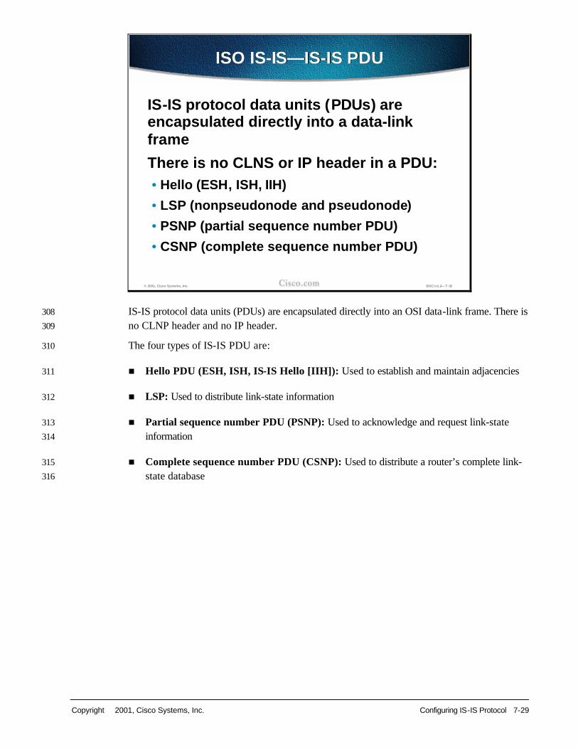
Insert Slide here. IS-IS protocol data units (PDUs) are encapsulated directly into an OSI data-link frame. There is 308
no CLNP header and no IP header. 309
The four types of IS-IS PDU are: 310
n Hello PDU (ESH, ISH, IS-IS Hello [IIH]): Used to establish and maintain adjacencies 311
n LSP: Used to distribute link-state information 312
n Partial sequence number PDU (PSNP): Used to acknowledge and request link-state 313
information 314
n Complete sequence number PDU (CSNP): Used to distribute a router’s complete link-315
state database 316
© 2001, Cisco Systems, Inc. BSCI v1.2— 7-30
ISO IS-IS—IS-IS PDUISO IS-IS—IS-IS PDU
IS-IS protocol data units (PDUs) are encapsulated directly into a data-link frame
There is no CLNS or IP header in a PDU:• Hello (ESH, ISH, IIH)
• LSP (nonpseudonode and pseudonode)
• PSNP (partial sequence number PDU)
• CSNP (complete sequence number PDU)

7-30 Building Scalable Cisco Internetworks (BSCI) v1.2 Copyright 2001, Cisco Systems, Inc.
Insert Slide here. The OSI stack defines a unit of data as a PDU. A frame is therefore regarded by OSI as a 317
data-link PDU, and a packet (or datagram, in the IP world) is regarded as a network PDU. 318
Three types of PDUs (802.2 Logical Link Control encapsulation) are shown in the figure. From 319
these it can be seen that the IS-IS and ES-IS PDUs are encapsulated directly in a data-link 320
PDU, while true CLNP (data) packets contain a full CLNP header between the data-link 321
header and any higher-layer CLNS information. 322
The IS-IS and ES-IS PDUs contain variable -length fields, depending on the function of the 323
PDU. Each field contains a type code, a length, and then the appropriate values, hence the 324
abbreviation TLV: Type, Length, Value fields. 325
© 2001, Cisco Systems, Inc. BSCI v1.2— 7-31
ISO IS-IS PDU—(cont.)ISO IS-IS PDU—(cont.)
PDU (protocol data unit) between peers• Network PDU = datagram, packet
• Data-link PDU = frame
Data-link header (OSI family 0xFEFE)
IS-IS header (first byte is 0x83)
IS-IS TLVsIS-IS:
Data-link header (OSI family 0xFEFE)
ES-IS header (first byte is 0x82)
ES-IS TLVsES-IS:
Data-link header (OSI family 0xFEFE)
CLNP header (first byte is 0x81)
CLNSCLNP
Copyright 2001, Cisco Systems, Inc. Configuring IS-IS Protocol 7-31
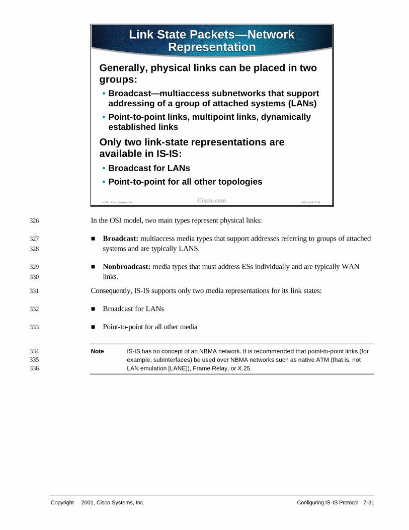
Insert Slide here. In the OSI model, two main types represent physical links: 326
n Broadcast: multiaccess media types that support addresses referring to groups of attached 327
systems and are typically LANS. 328
n Nonbroadcast: media types that must address ESs individually and are typically WAN 329
links. 330
Consequently, IS-IS supports only two media representations for its link states: 331
n Broadcast for LANs 332
n Point-to-point for all other media 333
Note IS-IS has no concept of an NBMA network. It is recommended that point-to-point links (for 334 example, subinterfaces) be used over NBMA networks such as native ATM (that is, not 335 LAN emulation [LANE]), Frame Relay, or X.25. 336
© 2001, Cisco Systems, Inc. BSCI v1.2— 7-32
Link State Packets—Network Representation
Link State Packets—Network Representation
Generally, physical links can be placed in two groups:• Broadcast—multiaccess subnetworks that support
addressing of a group of attached systems (LANs)
• Point-to-point links, multipoint links, dynamically established links
Only two link-state representations are available in IS-IS:• Broadcast for LANs
• Point-to-point for all other topologies
7-32 Building Scalable Cisco Internetworks (BSCI) v1.2 Copyright 2001, Cisco Systems, Inc.
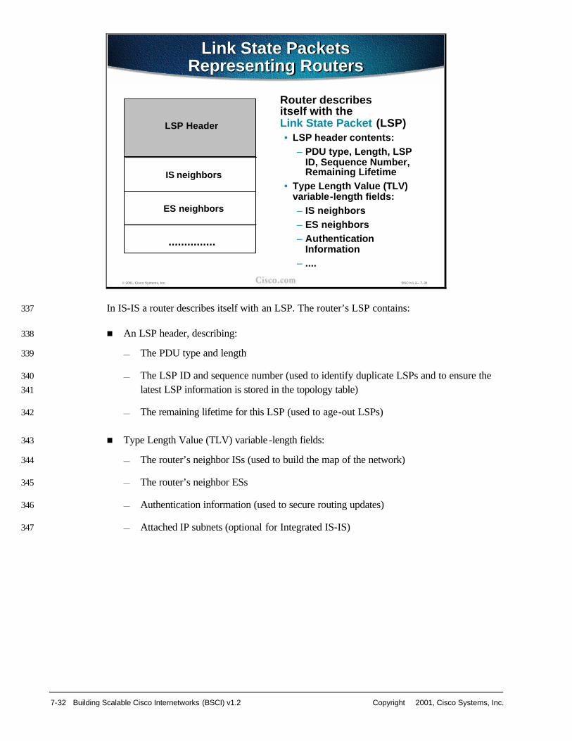
Insert Slide here. In IS-IS a router describes itself with an LSP. The router’s LSP contains: 337
n An LSP header, describing: 338
— The PDU type and length 339
— The LSP ID and sequence number (used to identify duplicate LSPs and to ensure the 340
latest LSP information is stored in the topology table) 341
— The remaining lifetime for this LSP (used to age-out LSPs) 342
n Type Length Value (TLV) variable -length fields: 343
— The router’s neighbor ISs (used to build the map of the network) 344
— The router’s neighbor ESs 345
— Authentication information (used to secure routing updates) 346
— Attached IP subnets (optional for Integrated IS-IS) 347
© 2001, Cisco Systems, Inc. BSCI v1.2— 7-33
Link State Packets Representing Routers
Link State Packets Representing Routers
Router describes itself with the Link State Packet (LSP)• LSP header contents:
– PDU type, Length, LSP ID, Sequence Number, Remaining Lifetime
• Type Length Value (TLV) variable-length fields:– IS neighbors– ES neighbors– Authentication
Information– ....
LSP Header
IS neighbors
ES neighbors
...............

Copyright 2001, Cisco Systems, Inc. Configuring IS-IS Protocol 7-33
Insert Slide here. LSPs are given sequence numbers, to enable receiving routers to ensure they use only the latest 348
LSPs in their route calculations and to avoid duplicate LSPs being entered in the topology tables. 349
When a router reloads, the sequence number is set initially to 1. The router may then receive its 350
own old LSPs back from its neighbors (which will have the last good sequence number before 351
the router reloaded). It records this number and reissues its own LSPs with the next highest 352
sequence number. 353
Each LSP has a “remaining lifetime” that is used by the LSP ageing process to ensure that 354
outdated and invalid LSPs are removed from the topology table after a suitable period. (Count to 355
zero operation - 1200 is a default start value.) 356
357
© 2001, Cisco Systems, Inc. BSCI v1.2— 7-34
LSP Representing Routers—LSP Header
LSP Representing Routers—LSP Header
LSPs are sequenced to prevent duplication of LSPs• Assists with synchronization• Sequence numbers begin with 1
Sequence numbers are increased to indicate newest LSP• LSPs in LSDB have a remaining lifetime• Allows synchronization• Decreasing timer

7-34 Building Scalable Cisco Internetworks (BSCI) v1.2 Copyright 2001, Cisco Systems, Inc.
Insert Slide here. Dijkstra’s algorithm requires a virtual router (pseudonode) for broadcast media to build a 358
directed graph. 359
For this reason, the Designated Intermediate System (DIS) is elected (by configurable priority, 360
then by highest MAC address) to generate an LSP representing a virtual router connecting all 361
attached routers to a star-shaped topology. 362
In IS-IS all routers on the LAN establish adjacencies with all other routers and with the DIS. 363
Thus, if the DIS fails, another router can take over immediately with little or no impact on the 364
topology of the network. 365
In OSPF, once the Designated Router (DR) and a Backup DR (BDR) are elected, the other 366
routers on the LAN establish adjacencies only with the DR and BDR (the BDR is elected and 367
then promoted to DR, in case of DR failure). 368
© 2001, Cisco Systems, Inc. BSCI v1.2— 7-35
LSP Representing Routers—LAN Representation
LSP Representing Routers—LAN Representation
IS IS
DIS IS IS
Pseudonode—logically “connected” to all other nodes
NOTE: All (physical) routers still establish adjacency to each other
Logical phisycal

Copyright 2001, Cisco Systems, Inc. Configuring IS-IS Protocol 7-35
Insert Slide here. The LSPs include specific information about the router’s attachments. This information is 369
included in multiple TLV fields in the main body of the LSP: 370
n The links to neighbor routers (ISs), including the metrics of those interfaces 371
n The links to neighbor ESs 372
— If Integrated IS-IS is operational, the attached IP subnets are described as ESs, using a 373
special TLV specified for IP information. 374
The metrics of IS-IS links are associated with the outgoing interface toward the neighbor IS 375
(router). Up to four metrics can be specified: 376
n Default (required): The only metric supported by Cisco IOS. 377
n Delay, Expense, and Error (optional): Intended for use in Type of Service (ToS) 378
routing. These could be used to calculate alternative routes referring to the DTR (Delay, 379
Throughput, Reliability) bits in the IP ToS field. 380
381
© 2001, Cisco Systems, Inc. BSCI v1.2— 7-36
LSP Representing Routers—Variables
LSP Representing Routers—Variables
Router specific information is encoded in the variable field with TLVs (Type Length Value)
Metric is associated with an outgoing interface• Four types (three optional, intended to be
used in Type of Service (ToS) routing)
• Delay, default, expense, and error—Cisco uses default metric only

7-36 Building Scalable Cisco Internetworks (BSCI) v1.2 Copyright 2001, Cisco Systems, Inc.
Insert Slide here. An IS-IS network is termed a domain (the equivalent of an autonomous system [AS]). Within 382
the domain is a two-level hierarchy: 383
n Level-1 ISs (the equivalent of OSPF internal nonbackbone routers) are responsible for 384
routing to ESs inside an area. 385
n Level-2 ISs (backbone routers in OSPF) route between areas only. 386
n Level-1-2 Intermediate ISs (equivalent to area border routers [ABRs] in OSPF) route 387
between areas and the backbone. They participate in the level-1 intra-area routing and the 388
level-2 interarea routing. 389
© 2001, Cisco Systems, Inc. BSCI v1.2— 7-37
L1, L2 and L1/L2 RoutersL1, L2 and L1/L2 Routers
Two-level structure of areas forms IS-IS domainsIntermediate Systems can be:• L1, level 1 (equivalent to OSPF internal
nonbackbone routers), responsible for intra-area routing
• L1/L2, level 1-2 (in OSPF these are area-border routers), performing intra- and interarea routing
• L2, level 2 (backbone routers in OSPF), interarea only

Copyright 2001, Cisco Systems, Inc. Configuring IS-IS Protocol 7-37
Insert Slide here. Level-1 routers are also referred to as station routers because they enable stations (ESs) to 390
communicate with each other and the rest of the network. 391
A contiguous group of level-1 routers defines an area. The level-1 routers maintain the level-1 392
database, which defines the picture of the area itself and its exit points to neighboring areas. 393
Level-2 routers are also referred to as area routers because they interconnect the level-1 areas. 394
Level-2 routers store a separate database, which contains only the interarea topology 395
information. 396
© 2001, Cisco Systems, Inc. BSCI v1.2— 7-38
L1 and L2 RoutersL1 and L2 Routers
Level-1 (L1) routers referred to as station routers • L1 routers constitute an area
• L1 routers keep one copy of the link-state database (its own area “picture”; intra-area information only)
• They enable “stations” (ESs) to communicate
Level-2 (L2) routers referred to as area routers• They store interarea information
• They interconnect areas

7-38 Building Scalable Cisco Internetworks (BSCI) v1.2 Copyright 2001, Cisco Systems, Inc.
Insert Slide here. Level 1-2 routers act as if they were two IS-IS routers: 397
n They support a level-1 function to communicate with the other level-1 routers in their area 398
and maintain the level-1 LSP information in a level-1 topology database. They inform other 399
level-1 routers that they are an exit point from the area. 400
n They support a level-2 function to communicate with the rest of the backbone and maintain 401
a level-2 topology database separately from their level-1 database. 402
IS-IS does not share the concept of an area 0 with OSPF. Rather, it can appear as a set of 403
distinct areas interconnected by a chain of level-2 routers, weaving their way through and 404
between the level-1 areas. 405
© 2001, Cisco Systems, Inc. BSCI v1.2— 7-39
L1/L2 RouterL1/L2 Router
• Level 1-2 (L1/L2) routers keep two separate copies of link-state databases
–For level 1 and level 2
– Inform L1 routers about an exit point
• Level 1 area is a collection of L1 and L1/L2 routers
• Backbone area (level 2) is a set of L1/L2 and L2 routers and has to be contiguous
Copyright 2001, Cisco Systems, Inc. Configuring IS-IS Protocol 7-39
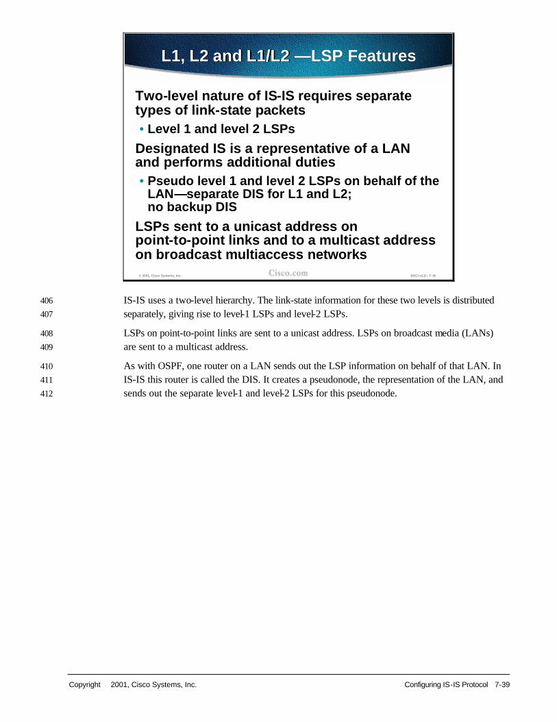
Insert Slide here. IS-IS uses a two-level hierarchy. The link-state information for these two levels is distributed 406
separately, giving rise to level-1 LSPs and level-2 LSPs. 407
LSPs on point-to-point links are sent to a unicast address. LSPs on broadcast media (LANs) 408
are sent to a multicast address. 409
As with OSPF, one router on a LAN sends out the LSP information on behalf of that LAN. In 410
IS-IS this router is called the DIS. It creates a pseudonode, the representation of the LAN, and 411
sends out the separate level-1 and level-2 LSPs for this pseudonode. 412
© 2001, Cisco Systems, Inc. BSCI v1.2— 7-40
L1, L2 and L1/L2 —LSP FeaturesL1, L2 and L1/L2 —LSP Features
Two-level nature of IS-IS requires separate types of link-state packets• Level 1 and level 2 LSPs
Designated IS is a representative of a LAN and performs additional duties• Pseudo level 1 and level 2 LSPs on behalf of the
LAN—separate DIS for L1 and L2; no backup DIS
LSPs sent to a unicast address on point-to-point links and to a multicast address on broadcast multiaccess networks

7-40 Building Scalable Cisco Internetworks (BSCI) v1.2 Copyright 2001, Cisco Systems, Inc.
Insert Slide here. Physically, a level-1-2 router connects to level-1 routers inside its area and to level-2 routers in 413
the backbone. 414
Note The boundary between areas in IS-IS exists on a link between routers and not on an ABR 415 itself, as in OSPF. 416
© 2001, Cisco Systems, Inc. BSCI v1.2— 7-41
Example #1: Area Configuration—Physical View
Example #1: Area Configuration—Physical View
Area-1 Area-2
R3 R2
R1 R4
L1L2 routers
L1 routers
R2 and R3 belong to their respective level-1 areas and provide a physical connection between them

Copyright 2001, Cisco Systems, Inc. Configuring IS-IS Protocol 7-41
Insert Slide here. Logically, the level-1-2 router acts (for the purposes of IS-IS routing) as if it were two logical 417
routers. It operates a: 418
n Level-1 routing process (with its own level-1 topology table and adjacency table) to other 419
level-1 routers (and ESs) 420
n Level-2 routing process (with a separate level-2 topology table and a separate level-2 421
adjacency table) to its neighbor backbone routers 422
© 2001, Cisco Systems, Inc. BSCI v1.2— 7-42
Example #1: Area Configuration—Logical View
Example #1: Area Configuration—Logical View
L1
R3 R2
R1 R4
R2 and R3 are still L1 routers, but, in addition, theyprovide an entry point to the level-2 backbone interconnecting both level-1 areas
L2
L2
L1 L1

7-42 Building Scalable Cisco Internetworks (BSCI) v1.2 Copyright 2001, Cisco Systems, Inc.
Insert Slide here. For example: 423
n Area 1 contains two routers: 424
— One router borders to area 2 and therefore is a level-1-2 IS. 425
— The other router is contained totally within the area and therefore is level-1-only. 426
n Area 2 has many routers: 427
— Some routers are specified as level-1-only and can route internally to that area only 428
(and to the exit points). 429
— Level-1-2 routers form a chain across the area linking to the neighbor areas. 430
— Even though the middle of these three level-1-2 routers does not link directly to another 431
area, it must support level-2 routing so the backbone is contiguous. 432
— If that middle router fails, the other level-1-only routers (though providing a physical 433
path across the area) could not perform the level-2 function, and the backbone would be 434
broken. 435
n Area 3 contains one router that borders to area 3, but has no intra-area neighbors, and is 436
therefore level-2-only. In the event that another router was added to area 3, the border 437
router would revert to level-1-2. 438
The diagram also shows that the border between the areas in an IS-IS network exists on the 439
links between level-2 routers (in contrast to OSPF where the border exists inside the ABR 440
itself). 441
© 2001, Cisco Systems, Inc. BSCI v1.2— 7-43
Example #2: L2 and L1/L2 Routers Forming L2 Backbone
Example #2: L2 and L1/L2 Routers Forming L2 Backbone
L1L2
L1L2
Backbone links
L1L2
L1L2
L1-only
L1-only
Area-2
Area-1
Area-3
Area-4L1-only
L1-only
L1L2
IS-IS domain
This router must behave as level 2 as well in order to guarantee backbone continuity.This router must behave as level 2 as well in order to guarantee backbone continuity.
L2-only

Copyright 2001, Cisco Systems, Inc. Configuring IS-IS Protocol 7-43
Insert Slide here. IS-IS uses hello PDUs to establish adjacencies with other routers (ISs) and ESs. Hello PDUs 442
carry information about the system, its parameters and capabilities. 443
444
© 2001, Cisco Systems, Inc. BSCI v1.2— 7-44
Identifying Types of Systems—Hello Messages
Identifying Types of Systems—Hello Messages
Periodic hello messages (hello PDU) are used,as in any other link-state protocol
Three types:
• ESH (End System Hello), between ES and IS
• ISH (Intermediate System Hello), sent by IS to ES
• IIH (IS-IS Hello, used between two ISs)
HELLOS carry information on the system itself, its capabilities and interface parameters

7-44 Building Scalable Cisco Internetworks (BSCI) v1.2 Copyright 2001, Cisco Systems, Inc.
Insert Slide here. There are three types of hello PDUs: 445
n The ESH is sent from an ES to an IS. 446
n The ISH is sent from an IS to an ES. 447
n The IIH is used between ISs. 448
449
© 2001, Cisco Systems, Inc. BSCI v1.2— 7-45
Identifying Types of Systems— ES and IS Hello Packets
Identifying Types of Systems— ES and IS Hello Packets
ES
IS-IS
ES-IS SNPA
ESES
SNPA
ESH
ISH
IIH
IS
IS
IS

Copyright 2001, Cisco Systems, Inc. Configuring IS-IS Protocol 7-45
Insert Slide here. ISs use IIHs to establish and maintain their neighbor relationships. Once an adjacency is 450
established, the ISs exchange link-state information with LSPs. 451
ISs also send out ISHs. ESs listen for these ISHs and randomly pick an IS (the first ISH they 452
hear) to forward all their packets to. Hence, OSI ESs require no configuration to forward 453
packets to the rest of the network. 454
455
© 2001, Cisco Systems, Inc. BSCI v1.2— 7-46
IS-IS and ES-IS CommunicationIS-IS and ES-IS Communication
Intermediate Systems establish and maintain neighbor relationships through the use of IS-IS hellos (IIHs) • Then they exchange LSPs
End Systems do not need any configuration for finding their respective IS• End Systems listen to Intermediate System
Hellos (ISHs) to find their “way to the world”
• Initially ES picks a router randomly (whichever is heard)

7-46 Building Scalable Cisco Internetworks (BSCI) v1.2 Copyright 2001, Cisco Systems, Inc.
Insert Slide here. ISs listen to the ESHs and learn about all the ESs on a segment. ISs include this information in 456
their LSPs. 457
For particular destinations, ISs may send redirect messages to ESs to provide them with an 458
optimal route off the segment. 459
© 2001, Cisco Systems, Inc. BSCI v1.2— 7-47
IS-IS and ES-IS Communication (cont.)
IS-IS and ES-IS Communication (cont.)
Routers listen to ESH and thus find all the end systems on a segment• Routers include information on end systems
in link-state packets
• Routers send redirect message to help ES in finding the most optimal exit from a segment

Copyright 2001, Cisco Systems, Inc. Configuring IS-IS Protocol 7-47
Insert Slide here. Separate adjacencies are established for level 1 and level 2. If two neighboring routers in the 460
same area run both level 1 and level 2, they will establish two adjacencies, one for each level. 461
The level-1 and level-2 adjacencies are stored in separate level-1 and level-2 adjacency tables. 462
On LANs, the two adjacencies are established with specific Layer 1 and Layer 2 IIH PDUs. 463
Routers on a LAN establish adjacencies with all other routers on the LAN (unlike OSPF, where 464
routers establish adjacencies only with the designated router). 465
On point-to-point links there is a common IIH format, part of which specifies whether the 466
HELLO relates to level 1, level 2, or both. 467
By default, hello PDUs are sent every 10 seconds; the timeout to declare a neighbor down is 30 468
seconds (that is, missing three hello packets). These timers can be reconfigured. 469
© 2001, Cisco Systems, Inc. BSCI v1.2— 7-48
Neighbors and AdjacenciesNeighbors and Adjacencies
IIH (IS-IS Hello) between routers• Two types of HELLOS on LAN—L1 and L2• Only one on p2p (with the type of desired adjacency
described—L1, L2 or both)• HELLOS sent every 10 seconds, holdtime 30 seconds
(default)
Separate adjacencies are built for L1 and L2 routers• L1/L2 routers keep two tables
Routers form adjacencies with all other routers and send LSPs to all routers on the LAN (unlike OSPF routers)

7-48 Building Scalable Cisco Internetworks (BSCI) v1.2 Copyright 2001, Cisco Systems, Inc.
Insert Slide here. IIH PDUs announce the area-ID. Separate IIH packets announce the level-1 and level-2 470
neighbors. 471
For example, where a LAN has routers from two areas attached: 472
n The routers from one area accept level-1 IIH PDUs only from their own area and therefore 473
establish adjacencies only with their own area routers. 474
n The routers from a second area similarly accept level-1 IIH PDUs only from their own 475
area. 476
n The level-2 routers (or the level-2 process within any level-1-2 router) accept only level-2 477
IIH PDUs and establish only level-2 adjacencies. 478
© 2001, Cisco Systems, Inc. BSCI v1.2— 7-49
LAN AdjacenciesLAN Adjacencies
L1
L1/L2 L1/L2 L1
L1 adjacency L2 adjanceny
Adjacencies are established based on the area address announced in the incoming IIHs and the type of the router
L1/L2 L1/L2
L1/L2
Area-1
Area-1
Area-1 Area-1
Area-2

Copyright 2001, Cisco Systems, Inc. Configuring IS-IS Protocol 7-49
Insert Slide here. On point-to-point links (that is, on a WAN), the IIH PDUs are common to both levels but 479
announce the level type and the area-ID in the HELLOs. 480
n Level-1 routers in the same area (which includes links between level-1 only and level-1-2 481
routers) exchange IIH PDUs specifying level-1 and establish a level-1 adjacency. 482
n Level-2 routers (in the same area or between areas, and including links between level-2-483
only and level-1-2 routers) exchange IIH PDUs specifying level-2 and establish a level-2 484
adjacency. 485
n Two level-1-2 routers in the same area establish both level-1 and level-2 adjacencies, and 486
maintain these with a common IIH PDU specifying both the level-1 and level-2 information. 487
n Two level-1 routers which may be physically connected but are not in the same area 488
(including a level-1 only to a level-1-2 router in a different level-1 area) exchange level-1 489
IIH PDUs but ignore these as the area-IDs do not match. Therefore, they do not establish 490
adjacency. 491
© 2001, Cisco Systems, Inc. BSCI v1.2— 7-50
WAN AdjacenciesWAN Adjacencies
L1 L1
L1/L2
Area-1 Area-1
L1/L2 L1 L1/L2
Area-1 Area-1
L1
L2 L2
Area-1 Area-1
Area-1 Area-2
L1
L1L2
L1
#
L1/L2 L2 L1/L2
Area-1 Area-1L2
L1/L2 L2 L1/L2
Area-1 Area-2L2
L2
L1/L2 L1/L2Area-1 Area-1

7-50 Building Scalable Cisco Internetworks (BSCI) v1.2 Copyright 2001, Cisco Systems, Inc.
Insert Slide here. The figure shows examples of: 492
n Level-1-only routers establishing level-1 adjacencies 493
n Level-2 routers establishing only level-2 adjacencies (between areas) 494
n Level-1-2 routers establishing both level-1 and level-2 adjacencies with their level-1-2 495
neighbors in the same area 496
Note L2 adjacency exists independent of area and must be contiguous (area 2 is not a 497 backbone area). 498
© 2001, Cisco Systems, Inc. BSCI v1.2— 7-51
Continous Flow of L2 AdjacenciesContinous Flow of L2 Adjacencies
L1L2
L1L2
L1L2
L2-only
L1-only
L1-only
L1L2
Area-1
Area-2 Area-3
L1 adjacenciesL2 adjacenciesL1 and L2 adjacencies
Area-1 and Area-2 are level-1 areasLevel-2 backbone is a set of L1/L2 and L2 routersand overlaps attached level-1 areas

Copyright 2001, Cisco Systems, Inc. Configuring IS-IS Protocol 7-51
Insert Slide here. Sequence number PDUs (SNPs) ensure LSPs are sent reliably. SNPs contain LSP descriptors; 499
not the actual, detailed LSP information, but headers describing the LSPs. 500
PSNPs usually contain only one LSP descriptor block. They are used: 501
n To acknowledge receipt of an LSP 502
n To request a complete LSP for an entry missing in the originating router’s topology 503
database 504
CSNPs are a list of the LSPs held by a router. 505
n CSNPs are sent periodically on LANs. Receiving routers can compare the list of LSPs in 506
the CSNP with their link-state database and request (with a PSNP) any missing LSPs. 507
n CSNPs are sent on point-to-point links when the link comes active. In Cisco IOS, periodic 508
CSNPs can be configured on point-to-point links. 509
© 2001, Cisco Systems, Inc. BSCI v1.2— 7-52
Link-State Database SynchronizationLink-State Database Synchronization
SNP (Sequence Number PDU) packets used to ensure synchronization and reliability• Contents are “LSP descriptions”
PSNP (Partial SNP) used:• For acknowledgment of LSPs on p2p links
• To request missing pieces of link-state database
CSNP (Complete SNP) used:• Periodically by DIS on LAN to ensure reliability
• On point-to-point link when the link comes up

7-52 Building Scalable Cisco Internetworks (BSCI) v1.2 Copyright 2001, Cisco Systems, Inc.
Insert Slide here. This figure shows the following example: 510
n A link fails. 511
n The middle router (R2) notices this failure and issues a new LSP noting the change. 512
n The left router (R1) receives the LSP, stores it in its topology table, and sends a PSNP back 513
to the middle router to acknowledge receipt of the LSP. 514
© 2001, Cisco Systems, Inc. BSCI v1.2— 7-53
Link-State Database Synchronization—P2PLink-State Database
Synchronization—P2P
R1 R3 LSP 33
PSNP
III. ACK: Thank you for
LSP 33
III. ACK: Thank you for
LSP 33I. Link went downI. Link
went down
II. New LSP describing the
current situation
II. New LSP describing the
current situation
s0R2

Copyright 2001, Cisco Systems, Inc. Configuring IS-IS Protocol 7-53
Insert Slide here. The DIS periodically (every 10 seconds) sends CSNPs listing the LSPs it holds in its link-state 515
database. This is a broadcast to all IS-IS routers on the LAN. 516
In the example, the bottom-left router (R1) compares this list of LSPs with its topology table and 517
realizes it is missing one LSP. Therefore, it sends a PSNP to the DIS (R2) to request the 518
missing LSP. The DIS reissues that LSP, and the bottom-left router acknowledges it with a 519
PSNP as in the previous diagram (not shown). 520
© 2001, Cisco Systems, Inc. BSCI v1.2— 7-54
Link-State Database Synchronization—LAN
Link-State Database Synchronization—LAN
R1
CSNP sent periodically (every 10 s) by DIS
R2/DIS
PSNP
II. Request:Sorry. I
missed LSP 77
II. Request:Sorry. I
missed LSP 77 CSNP PSNP
I. CSNP:LSP76LSP77LSP88
I. CSNP:LSP76LSP77LSP88

7-54 Building Scalable Cisco Internetworks (BSCI) v1.2 Copyright 2001, Cisco Systems, Inc.
IP and OSI Routing with Integrated IS-IS 521
Insert Slide here. Integrated IS-IS supports three types of networks: 522
n OSI 523
n IP 524
n Dual (that is, both the above) 525
The LSPs can contain many variable -length TLV fields, describing: 526
n OSI state information 527
n IP state information 528
© 2001, Cisco Systems, Inc. BSCI v1.2— 7-56
Integrated IS-IS Routing ProtocolIntegrated IS-IS Routing Protocol
Integrated IS-IS allows for three types of routing domains (OSI, IP, Dual)
Therefore, an IS-IS LSP may contain multiple variable-length fields (TLV)• Some contain OSI-specific information
• Some contain IP-specific information

Copyright 2001, Cisco Systems, Inc. Configuring IS-IS Protocol 7-55
Insert Slide here. Integrated IS-IS LSPs describe IP information in a similar manner to the way IS-IS describes 529
ESs. There are specific TLV types for IP information. 530
Like all modern routing protocols, Integrated IS-IS supports: 531
n Variable-Length Subnet Masks (VLSMs) - the mask is sent with the prefix in the updates 532
n Redistribution of IP routes into and out of IS-IS 533
n Summarization of IP routes 534
© 2001, Cisco Systems, Inc. BSCI v1.2— 7-57
Integrated IS-IS—Representing IP Networks
Integrated IS-IS—Representing IP Networks
LSP describes IP information in the same way as ESs
Integrated IS-IS has all the features of modern routing protocols• Variable-length mask
• Redistribution
• Summarization

7-56 Building Scalable Cisco Internetworks (BSCI) v1.2 Copyright 2001, Cisco Systems, Inc.
Insert Slide here. IS-IS can be enabled on Cisco routers for: 535
n Pure CLNS support 536
n IP support (Integrated IS-IS), additional to CLNS, or for IP only 537
However, even if Integrated IS-IS is being used only for IP routing, a NET address is required 538
for Layer 2 forwarding and Dijkstra’s algorithm computation: 539
n OSI protocols are used to form the neighbor relationship between routers. 540
n SPF calculations rely on a configured NET address to identify the routers. 541
© 2001, Cisco Systems, Inc. BSCI v1.2— 7-58
Integrated IS-IS—NET Address Planning
Integrated IS-IS—NET Address Planning
Common CLNS parameters (NET) and area planning are still required even in an IP environment• Even when Integrated IS-IS is used only
for IP routing, routers still establish CLNS adjacencies and use CLNS packets

Copyright 2001, Cisco Systems, Inc. Configuring IS-IS Protocol 7-57
Insert Slide here. To build the OSI forwarding database (the CLNS routing table): 542
n The link-state database is used to calculate the Shortest-Path-First (SPF) tree to OSI 543
destinations (NETs). The link metrics are totaled along each path to decide which is the 544
shortest to any given destination. 545
n There are separate link-state databases for level-1 and level-2 routes. Therefore, SPF is run 546
twice (once for each level), and separate SPF trees are created for each level. 547
n ES reachability is calculated with a partial route calculation (PRC) based on the above 548
level-1 and level-2 SPF trees. (There are no OSI ESs if it is a pure IP Integrated IS-IS 549
environment). 550
n The best paths are inserted in the CLNS routing table (OSI forwarding database). 551
© 2001, Cisco Systems, Inc. BSCI v1.2— 7-59
OSI Area Routing—Building OSI Forwarding Table
OSI Area Routing—Building OSI Forwarding Table
• When databases are synchronized, Dijkstra(SPF) algorithm is run on the LSDB to calculate the SPF tree
–Criteria: the shortest path to the destination is the lowest total sum of metrics
–Separate route calculations made for L1 and L2 areas in L1/L2 routers
• Partial route calculation (PRC) run to calculate ES reachability
• Best paths are placed in the OSI L1 and L2 forwarding tables

7-58 Building Scalable Cisco Internetworks (BSCI) v1.2 Copyright 2001, Cisco Systems, Inc.
Insert Slide here. Routing inside a level-1 area is based on the System ID of the destination OSI (NSAP) address. 552
OSI Packets to other areas are routed to the nearest level-1-2 router. 553
Level-2 routing is based on the area-ID. If a level-1-2 router receives a packet (from a level-2 554
neighbor) destined for its own area, it will route it as for level 1, based on the System ID. 555
© 2001, Cisco Systems, Inc. BSCI v1.2— 7-60
OSI Area RoutingOSI Area Routing
Level-1 intermediate systems• Routing within the area is based on the
System ID portion of the ISO address
• If the destination belongs to another area, they route to the nearest active level-1-2 router
Level-2 intermediate systems• Routing between areas is based on the area address
and considers only the area cost
• If the destination belongs to the same area, they use the least-cost path to the System ID

Copyright 2001, Cisco Systems, Inc. Configuring IS-IS Protocol 7-59
Insert Slide here. When routing a packet from one area that is destined for another area: 556
n The level-1 routers route the packet to the nearest level-1-2 router. They find the closest 557
exit point from the area, based on receipt of default routes from the level-1-2 routers in their 558
area. 559
n The level-1-2 router routes the packets into the level-2 backbone based on the destination 560
area-ID. The packet travels across the level-2 backbone to the destination area. 561
n Once it arrives in the destination area, level-1 routing is again used to route the packet to its 562
final destination inside that area. 563
The interface between the level-1 world and the level-2 world takes place on a level-1-2 router. 564
The level-1-2 router behaves as if it were both a level-1 router (routing to level-1 destinations) 565
and a level-2 router (routing between areas). 566
© 2001, Cisco Systems, Inc. BSCI v1.2— 7-61
OSI Area Routing—Routing Between Areas
OSI Area Routing—Routing Between Areas
From level 1 via level 2 to level 1• L1 always sends a packet to a nearest
active L1/L2 router (default routing)
• Then the packet travels via L2 routing towards the destination area where the best L1 path is used
Note: L1/L2 router performs L1 and L2 routing

7-60 Building Scalable Cisco Internetworks (BSCI) v1.2 Copyright 2001, Cisco Systems, Inc.
Insert Slide here. The fact that level-1 routers see a default route only to the nearest level-2 routers can lead to 567
suboptimal routing, as shown in the diagram. 568
Router R1 routes packets to Router R2 to its level-1-2 router. This router looks at the 569
destination area and routes directly into area 2. Once in area 2, the packets are routed as level 1 570
(even though the initial next hop is another level-1-2 router, the routing is level 1) to Router R2. 571
Return packets from Router R2 to Router R1 are routed by R2 to its nearest level-1-2 router. 572
This router happens to see the best route to area 1 as being via area 4 and routes the return 573
packets by a different route to the incoming packets. The path taken is not actually the least 574
cost from R2 to R1. 575
Asymmetric routing (packets in different directions taking different paths) is not necessarily 576
detrimental to the network but can make troubleshooting difficult. 577
A feature available since IOS Release 12.0 allows level-2 routes to be leaked in a controlled 578
manner into the level-1 area to help avoid this situation. 579
© 2001, Cisco Systems, Inc. BSCI v1.2— 7-62
OSI Area Routing—Suboptimal Interarea Routing
OSI Area Routing—Suboptimal Interarea Routing
L1L2
L1L2
L1L2L1L2
L2
Area-2
Area-1
Area-3
Area-4
Area-5
R2
R1
Network path from router R2 to R1Network path from router R1 to R2
L2
10
15
10
10
10
10 15
R2 takes the closest exit; then L1L2 takes the closest entry
10
10

Copyright 2001, Cisco Systems, Inc. Configuring IS-IS Protocol 7-61
Insert Slide here. An IS-IS domain is the equivalent of an IP AS. 580
IS-IS can support the interconnection of multiple domains: 581
n In a pure-OSI environment, ISO-IGRP (Cisco proprietary) interprets the initial domain 582
identifier (IDI) portion of CLNS routes and allows routing between domains. There is also a 583
standard OSI Interdomain Routing Protocol (IDRP), which provides the same function (but 584
is not supported by Cisco). 585
In an IP environment, an IP interdomain protocol is required. The most common of these is the 586
Border Gateway Protocol (BGP). 587
© 2001, Cisco Systems, Inc. BSCI v1.2— 7-63
OSI Area Routing— Interconnecting IS-IS Domains
OSI Area Routing— Interconnecting IS-IS Domains
IS-IS routing domain is a collection of IS-IS areas
When interconnecting IS-IS domains the following applies:• In pure IP-environment use BGP
• In pure CLNS use ISO-IGRP or static CLNS routes

7-62 Building Scalable Cisco Internetworks (BSCI) v1.2 Copyright 2001, Cisco Systems, Inc.
Insert Slide here. This diagram forms the basis for the following examples. 588
© 2001, Cisco Systems, Inc. BSCI v1.2— 7-64
Example #1: OSI Intra- and Interarea Routing
Example #1: OSI Intra- and Interarea Routing
Area 49.0001 Area 49.0002
R5 - L2 R2 - L1L2
R1 - L1
L2
L1
Routing in a two-level area structure
R4 - L1
L1
L1
S0
S1
S0
S1
E0 E0

Copyright 2001, Cisco Systems, Inc. Configuring IS-IS Protocol 7-63
Insert Slide here. The show isis topology command displays the least-cost paths to the destination NETs: 589
n The System ID shows the NET of the destination. IOS uses Dynamic Hostname Mapping 590
(RFC 2763) to map this to a hostname (a router’s hostname is included in its outgoing LSP), 591
where that hostname is available to the router. 592
n The Metric shows the sum of the metrics on the least-cost path to the destination. 593
n The next-hop router (IS) is shown, plus the interface through which that next hop is 594
reached, and the SNPA of that next hop (HDLC is shown as the next hop across a serial 595
line). 596
The output for Router R2 shows that separate topology databases exist for level 1 and level 2. 597
© 2001, Cisco Systems, Inc. BSCI v1.2— 7-65
Example #1—Level-1 and Level-2 Topology Table
Example #1—Level-1 and Level-2 Topology Table
R1#show isis topologyIS-IS paths to level-1 routersSystem Id Metric Next-Hop Interface SNPAR1 --R2 10 R2 Se0 *HDLC*R4 10 R4 Se1 *HDLC*
R2#show isis topologyIS-IS paths to level-1 routersSystem Id Metric Next-Hop Interface SNPAR1 10 R1 Se0 *HDLC*R2 --R4 10 R4 Se1 *HDLC*IS-IS paths to level-2 routersSystem Id Metric Next-Hop Interface SNPAR2 --R5 10 R5 Et0 0010.7bb5.9e20
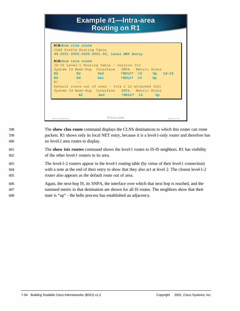
7-64 Building Scalable Cisco Internetworks (BSCI) v1.2 Copyright 2001, Cisco Systems, Inc.
Insert Slide here. The show clns route command displays the CLNS destinations to which this router can route 598
packets. R1 shows only its local NET entry, because it is a level-1-only router and therefore has 599
no level-2 area routes to display. 600
The show isis routes command shows the level-1 routes to IS-IS neighbors. R1 has visibility 601
of the other level-1 routers in its area. 602
The level-1-2 routers appear in the level-1 routing table (by virtue of their level-1 connection) 603
with a note at the end of their entry to show that they also act at level 2. The closest level-1-2 604
router also appears as the default route out of area. 605
Again, the next-hop IS, its SNPA, the interface over which that next hop is reached, and the 606
summed metric to that destination are shown for all IS routes. The neighbors show that their 607
state is “up” - the hello process has established an adjacency. 608
© 2001, Cisco Systems, Inc. BSCI v1.2— 7-66
Example #1—Intra-area Routing on R1
Example #1—Intra-area Routing on R1
R1#show clns routeCLNS Prefix Routing Table49.0001.0000.0000.0001.00, Local NET Entry
R1#show isis routeIS-IS Level-1 Routing Table - version 312System Id Next-Hop Interface SNPA Metric StateR2 R2 Se0 *HDLC* 10 Up L2-ISR4 R4 Se1 *HDLC* 10 UpR1 --Default route out of area - (via 2 L2-attached ISs)System Id Next-Hop Interface SNPA Metric State
R2 Se0 *HDLC* 10 Up

Copyright 2001, Cisco Systems, Inc. Configuring IS-IS Protocol 7-65
Insert Slide here. The same commands, executed on R2 give these results: 609
n show clns routing shows the local NET entry. It also shows the level-2 routes to its own, 610
and the neighbor, areas. 611
Note Level 2 regards the route to R2’s own area as being through itself - further emphasizing 612 that the level-1 and level-2 processes operate separately. 613
n show clns routes shows the IS-IS neighbors. 614
© 2001, Cisco Systems, Inc. BSCI v1.2— 7-67
Example #1—Intra- and InterareaRouting on R2
Example #1—Intra- and InterareaRouting on R2
R2#show clns routeCLNS Prefix Routing Table49.0001.0000.0000.0002.00, Local NET Entry49.0002 [110/10]
via R5, IS-IS, Up, Ethernet049.0001 [110/0]
via R2, IS-IS, Up
R2#show isis routeIS-IS Level-1 Routing Table - version 47System Id Next-Hop Interface SNPA Metric StateR4 R4 Se1 *HDLC* 10 UpR1 R1 Se0 *HDLC* 10 Up
R2#show clns routeCLNS Prefix Routing Table49.0001.0000.0000.0002.00, Local NET Entry49.0002 [110/10]via R5, IS-IS, Up, Ethernet0
49.0001 [110/0]via R2, IS-IS, Up
R2#show isis routeIS-IS Level-1 Routing Table - version 47System Id Next-Hop Interface SNPA Metric StateR4 R4 Se1 *HDLC* 10 UpR1 R1 Se0 *HDLC* 10 Up

7-66 Building Scalable Cisco Internetworks (BSCI) v1.2 Copyright 2001, Cisco Systems, Inc.
Insert Slide here. An alternative method of finding the route to a destination NET or NSAP is to use the which-615
route command. 616
In this case, the command is entered on the level-1-only router, R1.The command returns the 617
next hop to the destination and states whether the destination is reachable by level 1 or by the 618
default exit point to level 2. 619
© 2001, Cisco Systems, Inc. BSCI v1.2— 7-68
Example #1—Which Route in L1?Example #1—Which Route in L1?
R1#which-route 49.0001.0000.0000.0002.00 - (R2 NSAP)Route look-up for destination 49.0001.0000.0000.0002.00
Found route in IS-IS level-1 routing tableAdjacency entry used:System Id Interface SNPA State Holdtime Type Protocol0000.0000.0002 Se0 *HDLC* Up 26 L1 IS-IS
Area Address(es): 49.0001Uptime: 00:09:50
R1#which-route 49.0002.0000.0000.0005.00 - (R5 NSAP)Route look-up for destination 49.0002.0000.0000.0005.00
Using route to closest IS-IS level-2 routerAdjacency entry used:System Id Interface SNPA State Holdtime Type Protocol0000.0000.0002 Se0 *HDLC* Up 27 L1 IS-IS
Area Address(es): 49.0001Uptime: 00:09:57
R1#which-route 49.0001.0000.0000.0002.00 - (R2 NSAP)Route look-up for destination 49.0001.0000.0000.0002.00Found route in IS-IS level-1 routing table
Adjacency entry used:System Id Interface SNPA State Holdtime Type Protocol0000.0000.0002 Se0 *HDLC* Up 26 L1 IS-ISArea Address(es): 49.0001Uptime: 00:09:50
R1#which-route 49.0002.0000.0000.0005.00 - (R5 NSAP)Route look-up for destination 49.0002.0000.0000.0005.00Using route to closest IS-IS level-2 router
Adjacency entry used:System Id Interface SNPA State Holdtime Type Protocol0000.0000.0002 Se0 *HDLC* Up 27 L1 IS-ISArea Address(es): 49.0001Uptime: 00:09:57

Copyright 2001, Cisco Systems, Inc. Configuring IS-IS Protocol 7-67
Insert Slide here. Executing the which-route command on a level-2 router specifies the next hop and also states 620
that the route was matched by an entry from the CLNS level-2 routing table. 621
© 2001, Cisco Systems, Inc. BSCI v1.2— 7-69
Example #1—Which Route in L2?Example #1—Which Route in L2?
R5#which-route 49.0001.0000.0000.0002.00 (R2 NSAP)Found route in CLNS L2 prefix routing table
Route entry used:i 49.0001 [110/10] via R2, Ethernet0/0Adjacency entry used:System Id Interface SNPA State Hold. Type ProtR2 Et0/0 0000.0c92.e515 Up 24 L2 IS-IS
Area Address(es): 49.0001
R5#which-route 49.0001.0000.0000.0001.00 (R1 NSAP)Found route in CLNS L2 prefix routing tableRoute entry used:i 49.0001 [110/10] via R2, Ethernet0/0Adjacency entry used:System Id Interface SNPA State Hold. Type Prot.R2 Et0/0 0000.0c92.e515 Up 21 L2 IS-IS
Area Address(es): 49.0001
R5#which-route 49.0001.0000.0000.0002.00 (R2 NSAP)Found route in CLNS L2 prefix routing table
Route entry used:i 49.0001 [110/10] via R2, Ethernet0/0Adjacency entry used:System Id Interface SNPA State Hold. Type ProtR2 Et0/0 0000.0c92.e515 Up 24 L2 IS-ISArea Address(es): 49.0001
R5#which-route 49.0001.0000.0000.0001.00 (R1 NSAP)Found route in CLNS L2 prefix routing tableRoute entry used:i 49.0001 [110/10] via R2, Ethernet0/0Adjacency entry used:System Id Interface SNPA State Hold. Type Prot.R2 Et0/0 0000.0c92.e515 Up 21 L2 IS-ISArea Address(es): 49.0001

7-68 Building Scalable Cisco Internetworks (BSCI) v1.2 Copyright 2001, Cisco Systems, Inc.
Insert Slide here. So far, the process and outputs have referred to the OSI part of the IS-IS process. These are 622
the same as for pure OSI IS-IS routing. 623
However, in the IP world, when running Integrated IS-IS, IP information is included in the 624
LSPs. IP reachability behaves in IS-IS as if it were ES information. 625
IP information takes no part in the calculation of the SPF tree - it is simply information about 626
leaf connections to the tree. Therefore, updating the IP reachability is only a PRC (similar to ES 627
reachability). 628
IP routes are generated by the PRC and offered to the routing table, where they will be 629
accepted based on routing table rules comparing, for example, administrative distance. When 630
entered in the routing table, IP IS-IS routes are shown as being via level 1 or level 2, as 631
appropriate. 632
The separation of IP reachability from the core IS-IS network architecture gives Integrated IS-633
IS better scalability than, for example, OSPF: 634
n OSPF sends LSAs for individual IP subnets. If an IP subnet fails, then the LSA is flooded 635
through the network and, in all circumstances, all routers must run a full SPF calculation. 636
n In an Integrated IS-IS, the SPF tree is built from CLNS information. If an IP subnet fails in 637
Integrated IS-IS, the LSP is flooded as for OSPF. However, if this is a leaf IP subnet (that 638
is, the loss of the subnet has not affected the underlying CLNS architecture), the SPF tree 639
is unaffected and, therefore, only a PRC happens. 640
© 2001, Cisco Systems, Inc. BSCI v1.2— 7-70
Building IP Forwarding TableBuilding IP Forwarding Table
PRC is also run to calculate IP reachability• Since IP and ES are represented as leaf
objects they do not participate in SPF
Best paths are placed in the IP forwarding table following IP preferential rules• They appear as L1 or L2 IP routes

Copyright 2001, Cisco Systems, Inc. Configuring IS-IS Protocol 7-69
Insert Slide here. show ip route shows IP IS-IS routes in the IP routing table. The “i” indicates that the route 641
was sourced from IS-IS; “L1” and “L2” show whether the IS-IS path to these destination IP 642
networks is via IS-IS level-1 or level-2 routing. The next-hop IP addresses are matched from 643
the corresponding next-hop IS-IS neighbor routers. 644
© 2001, Cisco Systems, Inc. BSCI v1.2— 7-71
Building IP Forwarding Table (cont.)Building IP Forwarding Table (cont.)
Area 49.0001 Area 49.0002
R5- L2 R2 - L1L2
R1 - L1
L2
L1
R4 - L1
L1
L1
The IP addresses on loopbacks of routers are 1.0.0.1/8-R1, 2.0.0.1/8-R2, 4.0.0.1/8-R4 and 5.0.0.1/8-R5.R2#sh ip routei L1 1.0.0.0/8 [115/10] via 10.12.0.1, Ser0 -(R1)i L1 4.0.0.0/8 [115/10] via 10.24.0.4, Ser1 -(R4)i L2 5.0.0.0/8 [115/10] via 11.0.0.10, Eth0 -(R5)
The IP addresses on loopbacks of routers are 1.0.0.1/8-R1, 2.0.0.1/8-R2, 4.0.0.1/8-R4 and 5.0.0.1/8-R5.R2#sh ip routei L1 1.0.0.0/8 [115/10] via 10.12.0.1, Ser0 -(R1)i L1 4.0.0.0/8 [115/10] via 10.24.0.4, Ser1 -(R4)i L2 5.0.0.0/8 [115/10] via 11.0.0.10, Eth0 -(R5)
S0 S1
E0
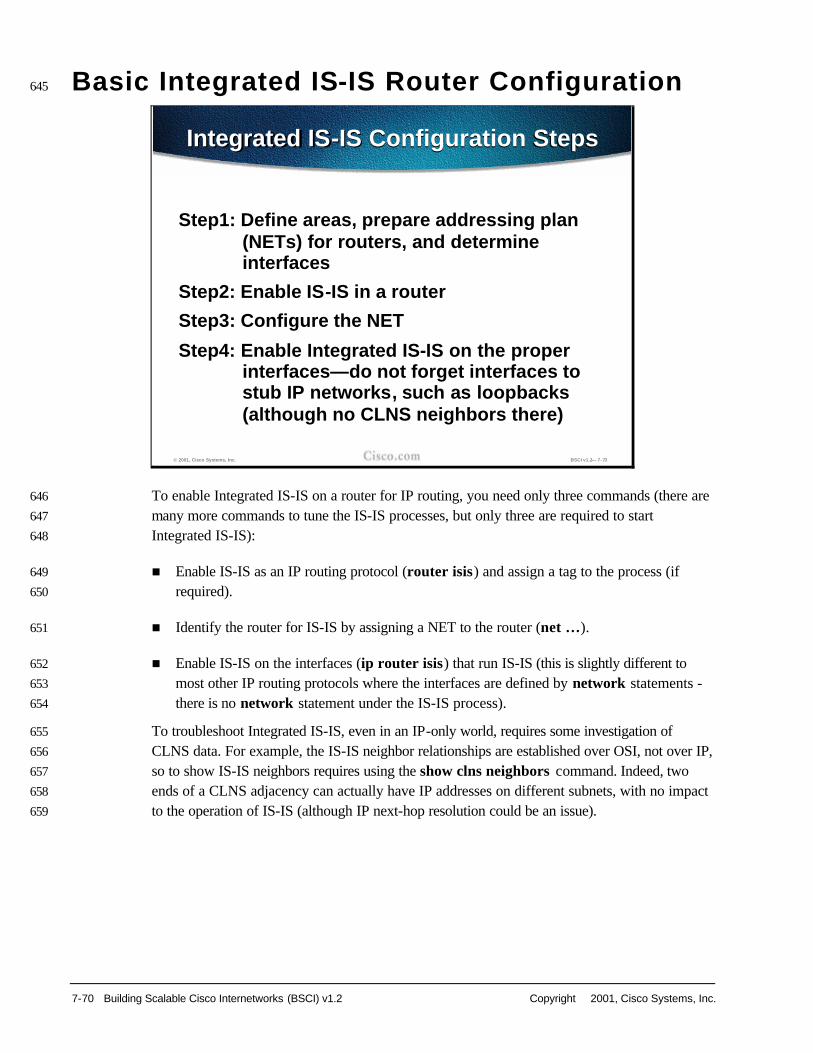
7-70 Building Scalable Cisco Internetworks (BSCI) v1.2 Copyright 2001, Cisco Systems, Inc.
Basic Integrated IS-IS Router Configuration 645
Insert Slide here. To enable Integrated IS-IS on a router for IP routing, you need only three commands (there are 646
many more commands to tune the IS-IS processes, but only three are required to start 647
Integrated IS-IS): 648
n Enable IS-IS as an IP routing protocol (router isis) and assign a tag to the process (if 649
required). 650
n Identify the router for IS-IS by assigning a NET to the router (net …). 651
n Enable IS-IS on the interfaces (ip router isis) that run IS-IS (this is slightly different to 652
most other IP routing protocols where the interfaces are defined by network statements - 653
there is no network statement under the IS-IS process). 654
To troubleshoot Integrated IS-IS, even in an IP-only world, requires some investigation of 655
CLNS data. For example, the IS-IS neighbor relationships are established over OSI, not over IP, 656
so to show IS-IS neighbors requires using the show clns neighbors command. Indeed, two 657
ends of a CLNS adjacency can actually have IP addresses on different subnets, with no impact 658
to the operation of IS-IS (although IP next-hop resolution could be an issue). 659
© 2001, Cisco Systems, Inc. BSCI v1.2— 7-73
Integrated IS-IS Configuration StepsIntegrated IS-IS Configuration Steps
Step1: Define areas, prepare addressing plan (NETs) for routers, and determine interfaces
Step2: Enable IS-IS in a router
Step3: Configure the NET
Step4: Enable Integrated IS-IS on the proper interfaces—do not forget interfaces to stub IP networks, such as loopbacks(although no CLNS neighbors there)

Copyright 2001, Cisco Systems, Inc. Configuring IS-IS Protocol 7-71
Insert Slide here. The commands to enable Integrated IS-IS are: 660
n The router is-is (global configuration) command enables Integrated IS-IS on the router. 661
Optionally, a tag can be applied to identify multiple IS-IS processes - if it is omitted, IOS 662
assumes a tag of 0. 663
n After the IS-IS process is enabled, the router must be identified for IS-IS by assigning a 664
network-entity-title to the router with the net (config-router) command. 665
n Finally, interfaces that are to use IS-IS to distribute their IP information (and additionally 666
may be used to establish IS-IS adjacencies) must be configured using the ip router is-is 667
interface command. If there is more than one IS-IS process, interfaces must state which 668
IS-IS process they belong to by specifying the appropriate tag. 669
These commands enable Integrated IS-IS on the router. However, further commands may be 670
required to tune the IS-IS operation. 671
© 2001, Cisco Systems, Inc. BSCI v1.2— 7-74
router isis [tag]router(config)#
• Enable the IS-IS routing protocol; tag—name for a process; when routing of clns packet is also needed use the clns routing command
IS-IS Configuration Steps—IS-IS Survival Kit Commands
IS-IS Configuration Steps—IS-IS Survival Kit Commands
ip router isis [tag]clns router isis [tag]
router(config-if)#
• Start an IS-IS routing process on an interface (IP, CLNS, both)
net network-entity-titlerouter(config-router)#
• Configure an IS-IS NET address for the routing process

7-72 Building Scalable Cisco Internetworks (BSCI) v1.2 Copyright 2001, Cisco Systems, Inc.
Insert Slide here. By default, Cisco IOS enables both level-1 and level-2 operations on IS-IS routers. If a router is 672
to operate only as an area router, or only as a backbone router, then this can be specified by 673
entering the is-type command (this is a router configuration command). To specify that the 674
router will act only as an area (or level-1) router, specify is-type level-1. To specify that the 675
router will act only as a backbone (or level-2) router, specify is-type level-2-only. 676
Similarly, although the router may be a level-1-2 router, it may be required to establish level-1 677
adjacencies only over certain interfaces and level-2 adjacencies over other interfaces. Thus, the 678
interface command isis circuit-type can specify either level-1 or level-2-only. If this is not 679
specified, the IOS will attempt to establish both types of adjacency over the interface. 680
Unlike some other IP protocols, IS-IS takes no account of line speed or bandwidth when setting 681
its link metrics. All interfaces are assigned a metric of 10. To change this value, you need to use 682
the interface command isis metric <value> level-1|level-2. The metric can have different 683
values for level 1 and level 2 over the same interface. 684
© 2001, Cisco Systems, Inc. BSCI v1.2— 7-75
is-type {level-1 | level-1-2 | level-2-only}router(config-router)#
• Configure the IS-IS level globally on a router; default = L1/L2 (station/area)
IS-IS Configuration Steps—IS-IS Good to Know Commands
IS-IS Configuration Steps—IS-IS Good to Know Commands
isis circuit-type {level-1 | level-1-2 | level-2-only}router(config-if)#
• Configure the type of adjacency on an interface; default = L1/L2
isis metric default-metric {level-1 | level-2}router(config-if)#
• Configure the metric for an interface; default = 10

Copyright 2001, Cisco Systems, Inc. Configuring IS-IS Protocol 7-73
Insert Slide here. This is an example of the simple Integrated IS-IS configuration, specifying only the IS-IS 685
process and the NET, and enabling IS-IS on the interfaces. This router will act as a level-1-2 686
router. 687
© 2001, Cisco Systems, Inc. BSCI v1.2— 7-76
IS-IS Configuration Steps—Simple Integrated IS-IS Example
IS-IS Configuration Steps—Simple Integrated IS-IS Example
The configured router acts as IP-only L1/L2 router
router isisnet 01.0001.0000.0000.0002.00!interface ethernet 0ip address 10.1.1.1 255.255.255.0ip router isis!interface serial 0ip address 10.1.2.1 255.255.255.0ip router isis
router isisnet 01.0001.0000.0000.0002.00
!interface ethernet 0ip address 10.1.1.1 255.255.255.0ip router isis
!interface serial 0ip address 10.1.2.1 255.255.255.0ip router isis

7-74 Building Scalable Cisco Internetworks (BSCI) v1.2 Copyright 2001, Cisco Systems, Inc.
Insert Slide here. This example shows how to configure a simple two-area IS-IS network, optimizing the level-1 688
and level-2 operations of the links and routers. 689
© 2001, Cisco Systems, Inc. BSCI v1.2— 7-77
Example #1: Sample Two-Area Configuration
Example #1: Sample Two-Area Configuration
Area 49.0001 Area 49.0002
R3 R2
R1 R4
L1L2 routers
L1 routers
E0
S0
Configure routers for routing IP within two-level area structure
S0 S0
S0
E0

Copyright 2001, Cisco Systems, Inc. Configuring IS-IS Protocol 7-75
Insert Slide here. Router R1 is in area 49.0001 with no links outside that area and, therefore, needs to operate 690
only as a level-1 router. 691
The is-type level-1 command under router isis ensures that the router creates only a level-1 692
database and takes part only in level-1 adjacencies over its interfaces - it is not necessary to 693
also specify the circuit-type on the interfaces in this case. Level 1 on the interfaces is implied 694
by setting the IS-IS process as level-1-only. 695
The serial interface has an isis metric set to better reflect the throughput of the line (compared 696
with, say, an Ethernet). 697
© 2001, Cisco Systems, Inc. BSCI v1.2— 7-78
Example #1: Sample Two-Area Configuration (L1 routers)
Example #1: Sample Two-Area Configuration (L1 routers)
R1 has to be L1-only router
hostname R1!interface Serial0ip address 192.168.120.1 255.255.255.0ip router isis!router isisis-type level-1net 49.0001.1921.6800.1005.00
hostname R1!interface Serial0ip address 192.168.120.1 255.255.255.0ip router isis
!router isisis-type level-1net 49.0001.1921.6800.1005.00

7-76 Building Scalable Cisco Internetworks (BSCI) v1.2 Copyright 2001, Cisco Systems, Inc.
Insert Slide here. Router R2 is a member of area 49.0001 but also links that area with the neighboring area 698
49.0002. Thus, it is required to act as both a level-1 and a level-2 router. This is the default 699
operation of router isis, so no specific configuration is required in the router definition. 700
However, to optimize the operation of the neighbor links, the interfaces to its two neighbors 701
specify the type of adjacency to be established. The interface toward Router R1 (in the same 702
area) specifies isis circuit-type level-1, while the interface toward Router R3 (different area, 703
hence level-2) has isis circuit-type level-2 specified. 704
Both interfaces have isis metrics defined as an example of this command. 705
© 2001, Cisco Systems, Inc. BSCI v1.2— 7-79
Example #1: Sample Two-Area Configuration (L1/L2 routers)
Example #1: Sample Two-Area Configuration (L1/L2 routers)
R2 has to be L1/L2-router (optimized)hostname R2!interface Ethernet0ip address 192.168.220.2 255.255.255.0ip router isisisis circuit-type level-2!interface Serial0ip address 192.168.120.2 255.255.255.0ip router isisisis circuit-type level-1!router isisnet 49.0001.1921.6800.1006.00
hostname R2!interface Ethernet0ip address 192.168.220.2 255.255.255.0ip router isisisis circuit-type level-2!interface Serial0ip address 192.168.120.2 255.255.255.0ip router isisisis circuit-type level-1!router isisnet 49.0001.1921.6800.1006.00

Copyright 2001, Cisco Systems, Inc. Configuring IS-IS Protocol 7-77
Insert Slide here. Some useful commands to troubleshoot the Integrated IS-IS network are: 706
n show clns displays general information about the CLNS network 707
n show clns protocol displays information for the specific IS-IS processes in the router 708
n show clns interface displays information about the interfaces running IS-IS. 709
n show clns neighbors is a very useful command, because it displays the neighbor ISs (and 710
ES neighbors, if there are any) - that is, the routers with which this router has IS-IS 711
adjacencies. The optional keyword detail displays comprehensive information about the 712
neighbors, rather than listing a summary of the neighbors, as is the case without that 713
keyword specified. The list can be reduced to those neighbors across a particular interface 714
by specifying the interface in the command. 715
© 2001, Cisco Systems, Inc. BSCI v1.2— 7-80
show clns
router#
• Display information about the CLNS network
Troubleshooting Commands—CLNSTroubleshooting Commands—CLNS
show clns protocol [tag]
router#
• List the protocol-specific information
show clns interface [type number]
router#
• List the CLNS-specific information about each interface
show clns neighbors [type number] [detail]
router#
• Display both ES and IS neighbors

7-78 Building Scalable Cisco Internetworks (BSCI) v1.2 Copyright 2001, Cisco Systems, Inc.
Insert Slide here. Further commands to troubleshoot the Integrated IS-IS network are: 716
n show isis route displays the IS-IS level-1 routing table (that is, all other System IDs in the 717
area) 718
n show clns route displays the IS-IS level-2 routing table 719
n show isis database displays the contents of the IS-IS link-state database 720
To force IS-IS to refresh its link-state database and recalculate all routes, issue the clear isis 721
command specifying the IS-IS process tag or * to clear all IS-IS 722
© 2001, Cisco Systems, Inc. BSCI v1.2— 7-81
show isis route
router#
• Display IS-IS level-1 routing table
Troubleshooting Commands—CLNS and IS-IS
Troubleshooting Commands—CLNS and IS-IS
show clns route
router#
• Display CLNS routing table
show isis database
router#
• Display the IS-IS link-state database

Copyright 2001, Cisco Systems, Inc. Configuring IS-IS Protocol 7-79
Insert Slide here. To troubleshoot the IP functionality of the Integrated IS-IS network, you can use standard IP 723
display commands: 724
n show ip protocols displays the active routing protocols, what interfaces they are active on, 725
and what networks they are routing for. 726
n show ip route displays the routing table. The detail for a particular route or a list of all 727
routes in the routing table from a particular process can be specified. 728
© 2001, Cisco Systems, Inc. www.cisco.com Overview of IS -IS Technologies, Structures and Protocols 82
show ip protocols
router#
• Display the parameters and current state of the active routing protocol process
Troubleshooting Commands—IPTroubleshooting Commands—IP
show ip route [address [mask]] | [protocol [process-id]]
router#
• Display the current state of the routing table

7-80 Building Scalable Cisco Internetworks (BSCI) v1.2 Copyright 2001, Cisco Systems, Inc.
Insert Slide here. This is an example output from the show clns protocols command showing: 729
n The Integrated IS-IS process, its tag (if present), and the level type(s) on the router 730
n The System ID and area-ID for this router 731
n The interfaces using Integrated IS-IS for routing (including whether that is for IP or CLNS 732
or both) 733
n Any redistribution of other route sources 734
n Information about the acceptance and generation of metrics, and distances for level-2 735
routing 736
© 2001, Cisco Systems, Inc. BSCI v1.2— 7-83
Example #2: Simple Troubleshooting—What About CLNS Protocol?
Example #2: Simple Troubleshooting—What About CLNS Protocol?
R2#show clns protocol
IS-IS Router: <Null Tag>System Id: 1921.6800.1006.00 IS-Type: level-1-2Manual area address(es):
49.0001Routing for area address(es):
49.0001Interfaces supported by IS-IS:
Serial0 - IPEethernet0 - IP
Redistribute:static (on by default)
Distance for L2 CLNS routes: 110RRR level: level-1Generate narrow metrics: level-1-2Accept narrow metrics: level-1-2Generate wide metrics: none Accept wide metrics: none

Copyright 2001, Cisco Systems, Inc. Configuring IS-IS Protocol 7-81
Insert Slide here. This is an example of output from the show clns neighbors command, showing: 737
n The IS-IS neighbors 738
n Their SNPAs and state 739
n The timeout (for receipt of no HELLOs) before the neighbor would be declared down 740
(holdtime) 741
n The neighbor’s level and type 742
The figure also provides an example of output from the show clns interfaces command, 743
showing: 744
n That the interface is running IS-IS and is attempting to establish both level-1 and level-2 745
adjacencies 746
n The interface numbers and circuit ID for IS-IS purposes 747
n The metric(s) for the interface and a priority for DIS negotiation (not relevant in this case 748
because it is a serial interface) 749
n Information about hello timers and the number of adjacencies that have been established 750
© 2001, Cisco Systems, Inc. BSCI v1.2— 7-84
Example #2: Are Adjacencies Established?
Example #2: Are Adjacencies Established?
R2#show clns neighborsSystem Id Interface SNPA State Holdtime Type ProtocolR1 Se0 *HDLC* Up 28 L1 IS-ISR3 Et0 0000.0c92.de4c Up 20 L2 IS-IS
R2#show clns interface serial 0Serial0 is up, line protocol is up
Checksums enabled, MTU 1500, Encapsulation HDLCERPDUs enabled, min. interval 10 msec.RDPDUs enabled, min. interval 100 msec., Addr Mask enabledCongestion Experienced bit set at 4 packetsCLNS fast switching disabledCLNS SSE switching disabledDEC compatibility mode OFF for this interfaceNext ESH/ISH in 12 secondsRouting Protocol: IS-ISCircuit Type: level-1Interface number 0x1, local circuit ID 0x101Level-1 Metric: 10, Priority: 64, Circuit ID: R2.00Number of active level-1 adjacencies: 1Next IS-IS Hello in 5 seconds
R2#show clns neighborsSystem Id Interface SNPA State Holdtime Type ProtocolR1 Se0 *HDLC* Up 28 L1 IS-ISR3 Et0 0000.0c92.de4c Up 20 L2 IS-IS
R2#show clns interface serial 0Serial0 is up, line protocol is upChecksums enabled, MTU 1500, Encapsulation HDLCERPDUs enabled, min. interval 10 msec.RDPDUs enabled, min. interval 100 msec., Addr Mask enabledCongestion Experienced bit set at 4 packetsCLNS fast switching disabledCLNS SSE switching disabledDEC compatibility mode OFF for this interfaceNext ESH/ISH in 12 secondsRouting Protocol: IS-ISCircuit Type: level-1Interface number 0x1, local circuit ID 0x101Level-1 Metric: 10, Priority: 64, Circuit ID: R2.00Number of active level-1 adjacencies: 1Next IS-IS Hello in 5 seconds

7-82 Building Scalable Cisco Internetworks (BSCI) v1.2 Copyright 2001, Cisco Systems, Inc.
Insert Slide here. This is an example of output from the show ip protocols command, showing that Integrated 751
IS-IS is running. It also shows the interfaces taking part in Integrated IS-IS and the sources of 752
routing information (the neighbor routers). 753
© 2001, Cisco Systems, Inc. BSCI v1.2— 7-85
Example #2: Is Integrated IS-IS Running?
Example #2: Is Integrated IS-IS Running?
R2#show ip protocols
Routing Protocol is "isis"Sending updates every 0 secondsInvalid after 0 seconds, hold down 0, flushed after 0Outgoing update filter list for all interfaces isIncoming update filter list for all interfaces isRedistributing: isisAddress Summarization:None
Routing for Networks:Serial0Ethernet0
Routing Information Sources:Gateway Distance Last Update11.0.0.1 115 00:11:4413.0.0.1 115 00:11:4414.0.0.1 115 00:11:44
Distance: (default is 115)

Copyright 2001, Cisco Systems, Inc. Configuring IS-IS Protocol 7-83
Insert Slide here. This is an example of output from the show ip route command, showing only the IS-IS routes. 754
These routes are all from level 1 as indicated by the “i L1” tag. 755
Integrated IS-IS uses an administrative distance of 115 by default the metric shown for each 756
route [115/20] is taken from the IS-IS cost to the destination. 757
© 2001, Cisco Systems, Inc. BSCI v1.2— 7-86
Example #2: Do We See Any IP Routes?
Example #2: Do We See Any IP Routes?
R2#show ip route isis
i L1 11.0.0.0/8 [115/10] via 192.168.20.1, Serial0i L1 13.0.0.0/8 [115/10] via 192.168.220.3, Ethernet0i L1 14.0.0.0/8 [115/20] via 192.168.220.3, Ethernet0
R2#show ip route isis
i L1 11.0.0.0/8 [115/10] via 192.168.20.1, Serial0i L1 13.0.0.0/8 [115/10] via 192.168.220.3, Ethernet0i L1 14.0.0.0/8 [115/20] via 192.168.220.3, Ethernet0
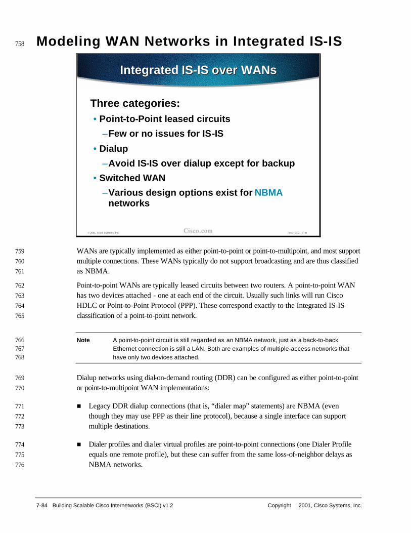
7-84 Building Scalable Cisco Internetworks (BSCI) v1.2 Copyright 2001, Cisco Systems, Inc.
Modeling WAN Networks in Integrated IS-IS 758
Insert Slide here. WANs are typically implemented as either point-to-point or point-to-multipoint, and most support 759
multiple connections. These WANs typically do not support broadcasting and are thus classified 760
as NBMA. 761
Point-to-point WANs are typically leased circuits between two routers. A point-to-point WAN 762
has two devices attached - one at each end of the circuit. Usually such links will run Cisco 763
HDLC or Point-to-Point Protocol (PPP). These correspond exactly to the Integrated IS-IS 764
classification of a point-to-point network. 765
Note A point-to-point circuit is still regarded as an NBMA network, just as a back-to-back 766 Ethernet connection is still a LAN. Both are examples of multiple-access networks that 767 have only two devices attached. 768
Dialup networks using dial-on-demand routing (DDR) can be configured as either point-to-point 769
or point-to-multipoint WAN implementations: 770
n Legacy DDR dialup connections (that is, “dialer map” statements) are NBMA (even 771
though they may use PPP as their line protocol), because a single interface can support 772
multiple destinations. 773
n Dialer profiles and dia ler virtual profiles are point-to-point connections (one Dialer Profile 774
equals one remote profile), but these can suffer from the same loss-of-neighbor delays as 775
NBMA networks. 776
© 2001, Cisco Systems, Inc. BSCI v1.2— 7-88
Integrated IS-IS over WANsIntegrated IS-IS over WANs
Three categories:• Point-to-Point leased circuits
–Few or no issues for IS-IS
• Dialup
–Avoid IS-IS over dialup except for backup
• Switched WAN
–Various design options exist for NBMA networks

Copyright 2001, Cisco Systems, Inc. Configuring IS-IS Protocol 7-85
n Dialer virtual profiles are point-to-point connections where the interface drops immediately 777
if the remote end disconnects, leading to faster neighbor-loss detection and faster 778
convergence. 779
Dial interfaces are not dealt with in this lesson. As a general rule, you should avoid IS-IS over 780
dialup, except to provide dial-backup functionality. 781

7-86 Building Scalable Cisco Internetworks (BSCI) v1.2 Copyright 2001, Cisco Systems, Inc.
Insert Slide here. IS-IS can work only over NBMA clouds configured with a full mesh. Anything less than a full 782
mesh could cause serious connectivity and routing issues. However, even if a full mesh is 783
configured, this is no guarantee that a full mesh will exist at all times. A failure in the underlying 784
switched WAN network, or a misconfiguration on one or more routers, could break the full 785
mesh either temporarily or permanently. Therefore, you should avoid NBMA multipoint 786
configurations for IS-IS networks. Use point-to-point subinterfaces instead. 787
Point-to-point interfaces should usually be configured with an IP subnet (that is, a 30-bit mask). 788
In modern IP networks using private addressing and/or variable -length subnetting, there are 789
usually plenty of spare IP addresses to apply to point-to-point interfaces. 790
Alternatively, as Integrated IS-IS uses CLNS packets for its route propagation, “ip 791
unnumbered” can be used on point-to-point interfaces. However, this works only on more 792
recent IOS releases (12.x) - earlier releases fail to establish an IS-IS adjacency because the IP 793
subnets do not match at either end of the link. Although “IP unnumbered” can be used by IS-IS, 794
it cannot be used in other routing protocols, such as OSPF. 795
© 2001, Cisco Systems, Inc. BSCI v1.2— 7-89
Configuring IS-IS in Switched WANs
Configuring IS-IS in Switched WANs
Don’t use the broadcast model on NBMA clouds• Supported and works nicely as long as all
VCs of a fully meshed topology are up (p2mp interfaces!)
Use p2p subinterfaces• Unnumbered (to loopback), or
• Each subinterface in its own subnet

Copyright 2001, Cisco Systems, Inc. Configuring IS-IS Protocol 7-87
Insert Slide here. To enable IS-IS over switched WAN media: 796
n Start the IS-IS process and assign NETs as usual 797
n On each NBMA interface: 798
— Design a mesh between the NBMA peers (full or partial). 799
— Configure point-to-point subinterfaces for each NBMA VC and assign IP addresses. 800
— Define the mapping of level-3 protocols/addresses to the VC. If manual mappings are 801
used (for example, x25 map, frame-relay map), then the CLNS mapping must specify 802
“broadcast” (to support routing packets), but the IP mapping does not require this (it is 803
used only for next-hop resolution). 804
— Start IS-IS processing on the subinterface (ip router isis). This command must not be 805
used on the “main” interface or that (multipoint) interface will generate a pseudonode 806
LSP for itself. 807
n You can use further tuning commands to control the flooding of link-state information with 808
timer and blocking commands (discussed later in this lesson). 809
© 2001, Cisco Systems, Inc. BSCI v1.2— 7-90
Configuring IS-IS—NBMA Configuration Steps
Configuring IS-IS—NBMA Configuration Steps
Start IS-IS routing process on a router and define NET(s)For each NBMA interface:• Configure the point-to-point subinterface• Assign appropriate virtual circuit and
address (CLNS, IP) to it• Define mapping• Start IS-IS on a subinterface
Optional: adjust timers and LSP flooding

7-88 Building Scalable Cisco Internetworks (BSCI) v1.2 Copyright 2001, Cisco Systems, Inc.
Insert Slide here. On a point-to-point link a single IIH PDU is sent. This can specify whether the adjacency is at 810
level-1, level-2 or both. 811
When the adjacency is established, each neighbor sends a CSNP describing the contents of its 812
link-state database. Each router then requests any missing LSPs from the neighbor using 813
PSNPs and acknowledges the receipt of the LSPs with PSNPs. 814
This activity reduces the amount of routing traffic across the point-to-point link - each router 815
exchanges only the information missing from its link-state database rather than the entire link-816
state database of its neighbor router. 817
© 2001, Cisco Systems, Inc. BSCI v1.2— 7-91
Configuring IS-IS (cont.)Configuring IS-IS (cont.)
On a p2p link, only one type of IS-IS Hello (IIH) regardless of level typeWhen adjacency on p2p link is established, LSPs get exchanged through CSNP (once only)• Missing LSPs not present in the received
CSNP are sent to neighbors• Missing pieces from CSNP not present in link-
state database requested by PSNP• Received LSPs acknowledged by PSNP

Copyright 2001, Cisco Systems, Inc. Configuring IS-IS Protocol 7-89
Insert Slide here. This is an example of a router network connected over Frame Relay and using point-to-point 818
subinterfaces. Each Frame Relay permanent virtual circuit (PVC) is treated as its own point-to-819
point network, with its own IP addresses. 820
The example is of a star network topology. It is important to note that the routers at the “points” 821
of the star are also configured with point-to-point subinterfaces even though (unlike the central 822
router) they connect to only one VC. This is the best practice for all routing protocols (it allows 823
further VCs to be added without affecting the existing VC, but it is imperative to IS-IS. A 824
“main” interface is a multipoint interface, even if it happens to have only one VC configured. If 825
the single VC were configured under a main interface, IS-IS would treat this as a broadcast 826
network and attempt to elect a DIS. Also, the adjacency would not establish because the 827
multipoint end would send broadcast, network-style HELLOs, but the central router would send 828
point-to-point hello PDUs. 829
© 2001, Cisco Systems, Inc. BSCI v1.2— 7-92
Example #1: Running IS-IS on P2P Links
Example #1: Running IS-IS on P2P Links
R4
R1
R2
R3
Frame Relay
10.1.1.2
10.1.1.6
10.1.1.10
DLCI 100
DLCI 200
DLCI 300
DLCI 400
DLCI 400
DLCI 400
p2p
p2p
p2p
Frame relay modelled as a collection of subnets (each sub-interface in its own subnet)
Frame relay modelled as a collection of subnets (each sub-interface in its own subnet)
interface s0/0.1 point-to-pointip address 10.1.1.1 255.255.255.252interface s0/0.2 point-to-pointip address 10.1.1.5 255.255.255.252interface s0/0.3 point-to-pointip address 10.1.1.9 255.255.255.252
interface s0/0.1 point-to-pointip address 10.1.1.1 255.255.255.252interface s0/0.2 point-to-pointip address 10.1.1.5 255.255.255.252interface s0/0.3 point-to-pointip address 10.1.1.9 255.255.255.252
Point-to-point sub-interfacesPoint-to-point sub-interfaces

7-90 Building Scalable Cisco Internetworks (BSCI) v1.2 Copyright 2001, Cisco Systems, Inc.
Insert Slide here. Here is the configuration of the central router from the previous example. It shows the 830
following: 831
n The encapsulation type (frame-relay) is set under the main interface (Serial0/0). No IP or 832
IS-IS configuration is included under the main interface. 833
n Three subinterfaces are defined; one for each VC. Each subinterface specifies: 834
— The IP address and subinterface for that point-to-point link: a different subnet for each 835
subinterface. 836
— Integrated IS-IS as the routing protocol over that subinterface (ip router isis). 837
— The VC to use for that point-to-point subinterface, using the frame-relay interface-838
dlci command. This is the only command needed to enable both IP and CLNS across 839
this VC. The router automatically enables, across this VC, all the protocols that are 840
enabled on the point-to-point subinterface, and “broadcast” for all those protocols. 841
© 2001, Cisco Systems, Inc. BSCI v1.2— 7-93
Example #1: Frame RelaySubinterface ConfigurationExample #1: Frame Relay
Subinterface Configuration
One router (R4) p2p FR subinterface (no maps)interface Serial0/0encapsulation frame-relay!interface Serial0/0.1 point-to-pointip address 10.1.1.1 255.255.255.252ip router isisframe-relay interface-dlci 100!interface Serial0/0.2 point-to-pointip address 10.1.1.5 255.255.255.252ip router isisframe-relay interface-dlci 200!interface Serial0/0.3 point-to-pointip address 10.1.1.9 255.255.255.252ip router isisframe-relay interface-dlci 300
interface Serial0/0encapsulation frame-relay
!interface Serial0/0.1 point-to-pointip address 10.1.1.1 255.255.255.252ip router isisframe-relay interface-dlci 100
!interface Serial0/0.2 point-to-pointip address 10.1.1.5 255.255.255.252ip router isisframe-relay interface-dlci 200
!interface Serial0/0.3 point-to-pointip address 10.1.1.9 255.255.255.252ip router isisframe-relay interface-dlci 300

Copyright 2001, Cisco Systems, Inc. Configuring IS-IS Protocol 7-91
Insert Slide here. This figure shows some monitoring commands for the example network: 842
n show frame-relay map displays the status of each Frame Relay VC, giving: 843
— Its status - “defined” means it has been configured on the Frame-Relay switch, and 844
“active” indicates that this VC is operational 845
— Its type - point-to-point, meaning it has been assigned to a point-to-point subinterface 846
— Its assigned subinterface - for example, Serial0/0.1 847
— The VC identification - for example, dlci 100 848
— Whether it supports broadcast (for example, routing) packets 849
n debug isis adj-packet shows the neighborship establishment across one of the 850
subinterfaces (Serial0/0.1); sending and receiving serial (that is, point-to-point) IIH PDUs 851
and declaring the adjacency “up.” Ongoing hello conversations for the other subinterfaces 852
are also shown. 853
© 2001, Cisco Systems, Inc. BSCI v1.2— 7-94
Example #1: Frame RelayMapping and Neighbors
Example #1: Frame RelayMapping and Neighbors
R4#show frame-relay mapSerial0/0.1 (up): point-to-point dlci, dlci 100(0x64,0x1840), broadcast
status defined, activeSerial0/0.2 (up): point-to-point dlci, dlci 200(0xC8,0x3080), broadcast
status defined, activeSerial0/0.3 (up): point-to-point dlci, dlci 300(0xA4,0x4580), broadcast
status defined, active
R4#debug isis adj-packetISIS-Adj: Sending serial IIH on Serial0/0.1, length 1499ISIS-Adj: Rec serial IIH from DLCI 100 (Serial0/0.1), cir type L1L2, cir id 00, length 1499ISIS-Adj: rcvd state UP, old state UP, new state UPISIS-Adj: Action = ACCEPT...ISIS-Adj: Sending serial IIH on Serial0/0.2, length 1499ISIS-Adj: Rec serial IIH from DLCI 200 (Serial0/0.2), cir type L1L2, cir id 01, length 1499ISIS-Adj: Sending serial IIH on Serial0/0.3, length 1499ISIS-Adj: Rec serial IIH from DLCI 300 (Serial0/0.3), cir type L1L2, cir id02, length 1499

7-92 Building Scalable Cisco Internetworks (BSCI) v1.2 Copyright 2001, Cisco Systems, Inc.
Insert Slide here. The alternative NBMA version of the example network is shown in this figure. In this case, all 854
the Frame Relay ports are configured as multipoint interfaces, either as a multipoint subinterface 855
(on the central router R4) or, possibly, the “main” interfaces on the other routers. All interfaces 856
share the same IP subnet. 857
The diagram shows the star topology from the previous example. In a multipoint environment it 858
is important that a full mesh be implemented; therefore, all other routers will also have VCs 859
interconnecting them, although these are not shown in the diagram. 860
If this were a true hub-and-spoke environment, and the spoke sites had no need to communicate 861
to each other, this topology could work with only the indicated DLCIs. In this case, the central 862
router (R4) must become the DIS for the NBMA network (as it is the only router visible to all 863
others), so a suitable IS-IS priority should be set on the Frame Relay interface. Routes would be 864
installed in each spoke router toward the other spoke routers via their local IP addresses. 865
However, packets to these destinations would be dropped, as there are no direct VCs between 866
the spokes. 867
© 2001, Cisco Systems, Inc. BSCI v1.2— 7-95
Example #2: Running IS-IS on P2MP Links
Example #2: Running IS-IS on P2MP Links
R1
R2
R3
Frame Relays0/0.2multipoint
10.0.0.4
10.0.0.1
10.0.0.2
10.0.0.3
DLCI 100
DLCI 200
DLCI 300
DLCI 400
DLCI 400
DLCI 400
p2mp
p2mp
p2mp
Outgoing (locally significant) DLCI to
which remote IP address (Inverse ARP) and CLNS protocols are mapped
Outgoing (locally significant) DLCI to
which remote IP address (Inverse ARP) and CLNS protocols are mapped
Frame Relay modeled as one IP subnet (full mesh needed although
not shown in the picture)
Frame Relay modeled as one IP subnet (full mesh needed although
not shown in the picture)
R4
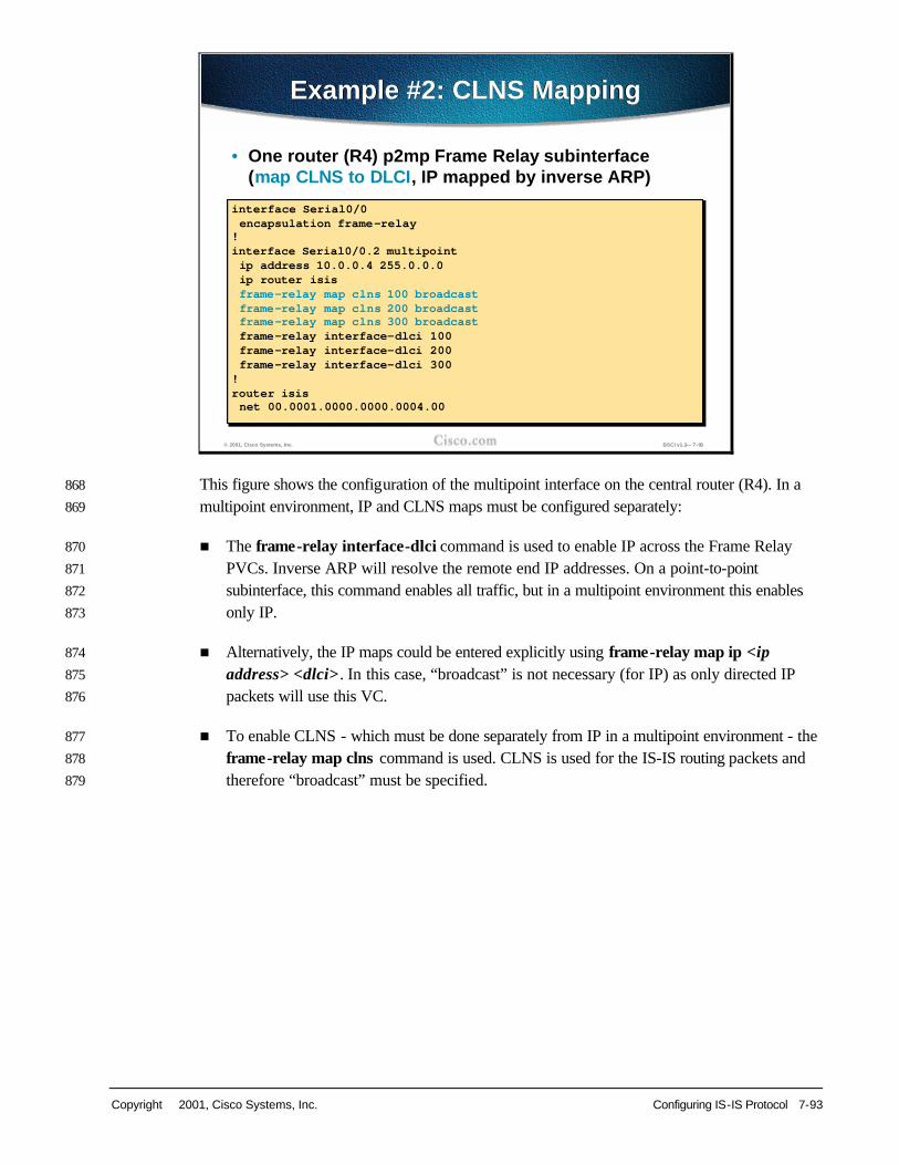
Copyright 2001, Cisco Systems, Inc. Configuring IS-IS Protocol 7-93
Insert Slide here. This figure shows the configuration of the multipoint interface on the central router (R4). In a 868
multipoint environment, IP and CLNS maps must be configured separately: 869
n The frame-relay interface-dlci command is used to enable IP across the Frame Relay 870
PVCs. Inverse ARP will resolve the remote end IP addresses. On a point-to-point 871
subinterface, this command enables all traffic, but in a multipoint environment this enables 872
only IP. 873
n Alternatively, the IP maps could be entered explicitly using frame-relay map ip <ip 874
address> <dlci> . In this case, “broadcast” is not necessary (for IP) as only directed IP 875
packets will use this VC. 876
n To enable CLNS - which must be done separately from IP in a multipoint environment - the 877
frame-relay map clns command is used. CLNS is used for the IS-IS routing packets and 878
therefore “broadcast” must be specified. 879
© 2001, Cisco Systems, Inc. BSCI v1.2— 7-96
Example #2: CLNS MappingExample #2: CLNS Mapping
interface Serial0/0encapsulation frame-relay!interface Serial0/0.2 multipointip address 10.0.0.4 255.0.0.0ip router isisframe-relay map clns 100 broadcastframe-relay map clns 200 broadcastframe-relay map clns 300 broadcastframe-relay interface-dlci 100frame-relay interface-dlci 200frame-relay interface-dlci 300!router isisnet 00.0001.0000.0000.0004.00
interface Serial0/0encapsulation frame-relay
!interface Serial0/0.2 multipointip address 10.0.0.4 255.0.0.0ip router isisframe-relay map clns 100 broadcastframe-relay map clns 200 broadcastframe-relay map clns 300 broadcastframe-relay interface-dlci 100frame-relay interface-dlci 200frame-relay interface-dlci 300
!router isisnet 00.0001.0000.0000.0004.00
• One router (R4) p2mp Frame Relay subinterface (map CLNS to DLCI, IP mapped by inverse ARP)

7-94 Building Scalable Cisco Internetworks (BSCI) v1.2 Copyright 2001, Cisco Systems, Inc.
Insert Slide here. This figure shows how the same monitoring commands, as used previously, produce a slightly 880
different output for the multipoint environment. 881
Some monitoring commands are shown for the example network: 882
n show frame-relay map again displays the status of each Frame Relay VC. This time, 883
separate entries are created for the IP and CLNS mappings (even though they use the 884
same VC): 885
— The CLNS map shows that it is created as a “static” map and that “broadcast” was 886
specified 887
— The IP map is “dynamic” because the IP address was resolved by Inverse ARP 888
n debug isis adj-packet again shows the neighborship establishment. This time, the 889
adjacency uses LAN IIH PDUs because this is a multipoint environment. 890
© 2001, Cisco Systems, Inc. BSCI v1.2— 7-97
Example #2: Frame RelayMapping and Neighbors
Example #2: Frame RelayMapping and Neighbors
R4#show frame-relay mapSerial0/0.4 (up): CLNS dlci 400(0x190,0x6400), static,
broadcast,CISCO, status defined, active
Serial0/0.4 (up): ip 10.1.4.3 dlci 400(0x190,0x6400), dynamic,broadcast,, status defined, active
R4#debug isis adj-packetISIS-Adj: Sending L2 LAN IIH on Serial0/0.2, length 1500ISIS-Adj: Rec L2 IIH from DLCI 400 (Serial0/0.2), cir type L1L2, cir id 0000.0000.0004.03, length 1500ISIS-Adj: Sending L1 LAN IIH on Serial0/0.2, length 1500ISIS-Adj: Rec L1 IIH from DLCI 400 (Serial0/0.2), cir type L1L2, cir id 0000.0000.0004.03, length 1500

Copyright 2001, Cisco Systems, Inc. Configuring IS-IS Protocol 7-95
Insert Slide here. An example of a misconfiguration is shown. One end of a link (R2) is specified as a point-to-891
point subinterface, but the other (R4) is using a point-to-multipoint interface. 892
Issuing the show clns neighbors on each router shows the mismatch: 893
n R2 (the point-to-point end) shows the adjacency as “up” 894
n R4 (the multipoint end), the adjacency is stuck in the init state 895
The misconfiguration results from the fact that the two ends of the VC are set to different 896
types. The point-to-point end sends Serial IIH PDUs. The multipoint end sends LAN IIH 897
PDUs. 898
© 2001, Cisco Systems, Inc. BSCI v1.2— 7-98
Detecting Mismatched InterfacesDetecting Mismatched Interfaces
One router (R4) configured as p2mp (sending LAN IIHs), the other (R2) as p2p (sending p2p IIHs)
Question: Why is the adjacency UP on p2p but stays in INIT on the p2mp side?R2#show clns neighborsSystem Id Interface SNPA State Holdtime Type Protocol0000.0000.0004 Se0/0.2 DLCI 300 Up 8 L1 IS-ISR5 Et0/0 0050.3ef1.5960 Up 8 L2 IS-ISR1 Se0/0.1 DLCI 100 Up 23 L1 IS-IS
R4#show clns neighborsSystem Id Interface SNPA State Holdtime Type ProtocolR6 Et0/0 0010.117e.74a8 Up 26 L2 IS-ISR3 Se0/0.3 DLCI 400 Up 28 L2 IS-IS0000.0000.0002 Se0/0.2 DLCI 300 Init 29 L1 IS-IS0000.0000.0001 Se0/0.1 DLCI 200 Up 290 IS ES-IS
R2#show clns neighborsSystem Id Interface SNPA State Holdtime Type Protocol0000.0000.0004 Se0/0.2 DLCI 300 Up 8 L1 IS-ISR5 Et0/0 0050.3ef1.5960 Up 8 L2 IS-ISR1 Se0/0.1 DLCI 100 Up 23 L1 IS-IS
R4#show clns neighborsSystem Id Interface SNPA State Holdtime Type ProtocolR6 Et0/0 0010.117e.74a8 Up 26 L2 IS-ISR3 Se0/0.3 DLCI 400 Up 28 L2 IS-IS0000.0000.0002 Se0/0.2 DLCI 300 Init 29 L1 IS-IS0000.0000.0001 Se0/0.1 DLCI 200 Up 290 IS ES-IS

7-96 Building Scalable Cisco Internetworks (BSCI) v1.2 Copyright 2001, Cisco Systems, Inc.
Insert Slide here. The ISO standard defines a three-way handshake for initiating LAN adjacencies: 899
n The adjacency starts in the “down” state. The IS sends out LAN IIH PDUs (identifying 900
itself). 901
n If a LAN IIH PDU is received, the adjacency is installed in the init state. This router then 902
sends out an IIH PDU to the neighbor, including the neighbor's SNPA in the hello packet. 903
The neighbor does the same thing with this router’s SNPA. 904
n The IS receives a second IIH from the neighbor router with its own SNPA identified in the 905
packet. On receipt of this, the IS understands that the new neighbor knows of its presence 906
and therefore declares the adjacency “up.” 907
According to the ISO standard (ISO 10589), this process is omitted for a point-to-point 908
adjacency. However, Cisco IOS implements the same three-way handshake by adding a Point-909
to-Point Adjacency State TLV (TLV 240) in the serial hello PDUs. In a similar manner to the 910
LAN adjacency, the router checks for its own SNPA in the neighbor's hello PDU before 911
declaring the adjacency “up.” 912
© 2001, Cisco Systems, Inc. BSCI v1.2— 7-99
Detecting Mismatched Interfaces (cont.)
Detecting Mismatched Interfaces (cont.)
Answer: This type of configuration is illegal• LAN adjacencies have a type of “three-way-hand
shake" (Down-Init-Up)• For such a handshake on p2p links, Cisco
introduced TLV 240 – In ISO 10589 bidirectionality is only checked
during the SPF computation• An adjacency is Up if the other side puts your
identity in the hello packet– Is valid if a previous match is found (Area
Address, Protocol Supported, IP Interface Address) for a certain level

Copyright 2001, Cisco Systems, Inc. Configuring IS-IS Protocol 7-97
Insert Slide here. The result of the example mismatch depends on the IOS release level. Prior to Release 913
12.1(1)T: 914
n R4 (multipoint) receives the point-to-point HELLO from R2 but treats it as a LAN HELLO 915
and puts the adjacency in the init state. It looks for its own SNPA in the received hello 916
PDUs (in a LAN hello PDU this would be identified in TLV 6 - IS Neighbors - but this 917
TLV is not present in a serial HELLO) but never finds them; therefore, the adjacency 918
remains in the init state. 919
n R2 (point-to-point) receives a LAN hello PDU and treats it as a point-to-point HELLO. It 920
checks the HELLO for a TLV 240 (point-to-point adjacency state) and fails to find one. For 921
backward compatibility, or perhaps to allow the link to be made to a non-Cisco IS-IS device, 922
the router assumes this is an ISO-specified point-to-point link, ignores the Cisco three-way 923
handshake, and allows the adjacency to establish, setting it to “up.” 924
Since Release 12.1(1)T: 925
n R4 (multipoint) receives the point-to-point HELLO, realizes it is the wrong hello type, and 926
installs the neighbor as an ES. R4 would show R2 in the show clns neighbors with 927
protocol “ES-IS.” 928
R2 (point-to-point) receives the LAN HELLO, recognizes the mismatch, and ignores the 929
neighbor. R4 would not appear at all in R2's show clns neighbors output. A debug isis adj-930
packets output shows the incoming LAN IIH PDU and R2 declaring the mismatch. 931
© 2001, Cisco Systems, Inc. BSCI v1.2 — 7-100
Detecting Mismatched Interfaces (cont.)
Detecting Mismatched Interfaces (cont.)
R4 (p2mp) receives a p2p IIH, and doesn't realize it is a p2p IIH • Creates a (LAN) adjacency• Looks for a TLV 6, doesn't find it, so it puts the
adjacency in INIT
R2 (p2p) receives a LAN IIH, and doesn't realize it is a LAN IIH• Creates a (p2p) adjacency• There is no TLV 240 in the packet, so the router omits
the three-way handshake for backwards compatibility, and puts the adjacency in the Up state– Fixed since IOS 12.1(1)T

7-98 Building Scalable Cisco Internetworks (BSCI) v1.2 Copyright 2001, Cisco Systems, Inc.
Summary 932
MISSING SLIDE 933
Insert Slide here. 934
935 936
© 2001, Cisco Systems, Inc. BSCI v1.2 — 7-101
SummarySummary
After completing this lesson, you should be able to:• Explain basic OSI terminology and network layer
protocols used in OSI• Identify similarities and differences between
Integrated IS-IS and OSPF• Identify characteristics of an effective addressing
plan for IS-IS deployment• Explain how networks and interfaces are
represented in IS-IS• List the types of IS-IS routers and their role in IS-IS
area design• Describe the hierarchical structure of IS-IS areas
© 2001, Cisco Systems, Inc. BSCI v1.2 — 7-102
Summary (cont.)Summary (cont.)
• Describe the concept of establishing adjacencies
• Describe the concepts of routing traffic transport and database synchronization
• Explain the basic principles of area routing
• Explain IS-IS NBMA (non-broadcast multi-access network) modeling solutions in switched WAN networks
• Given an addressing scheme and other laboratory parameters, identify the steps to configure Cisco routers for proper Integrated IS-IS operation
• Identify verification methods which ensure proper operation of Integrated IS-IS on Cisco routers

Copyright 2001, Cisco Systems, Inc. Configuring IS-IS Protocol 7-99
Review Questions 937
Answer the following questions. Appendix C contains answers to written exercises, review questions, and 938
laboratory exercises. 939
940 941 942 943 944 945 946 947 948 949 950 951 952 953 954 955 956 957 958 959 960 961
962 MISSING SLIDE
© 2001, Cisco Systems, Inc. BSCI v1.2 — 7-103
Review QuestionsReview Questions
1. What is common to OSPF and Integrated IS-IS?2. How is the router identified in an IS-IS environment?3. What is the difference between NSAP and NET?4. What does a unique System ID define?5. Which network representations are supported
by IS-IS?6. What is a pseudonode?7. How do two level-1 areas communicate?8. How do systems find each other in IS-IS?9. List the types of adjacencies between IS-IS systems.10. How is IS-IS routing enabled on Cisco routers?

7-100 Building Scalable Cisco Internetworks (BSCI) v1.2 Copyright 2001, Cisco Systems, Inc.
962 963 964 965