building regulations for the conservation of fuel & … regulations for the conservation of fuel...
TRANSCRIPT
Insulation
Low Energy –Low Carbon Buildings
ENGLAND – NEW DWELLINGS – 2013 EDITION
Building Regulations for theConservation of Fuel & Power
CI/SfBRn7 M2
First Issue March 2014

2
3
ContentsPage
Introduction 4
Approved Document L1A – New Dwellings 5Introduction 5Types of Work Covered 5Complying with Building Regulations 6CO2 Emissions & Fabric Energy Efficiency 7Limits to Design Flexibility 10Linear Thermal Bridging 11Air–permeability Testing 12Other Requirements 12Simplifying the Complex 13
Kingspan Insulation Solutions 14Construction & U–values 14Pitched Roof – Insulation Between & Under Rafters 15Pitched Roof – Insulation Between & Over Rafters 16Flat Roof – Concrete Deck with Suspended Plasterboard Ceiling 17Cavity Wall – Cavity Insulation Only 18Cavity Wall – Cavity Insulation & Insulated Dry–Lining on Dabs 19Timber Frame Wall – Insulation between Timber Studs & Insulated Dry–Lining 20Solid Blockwork Wall 21Rainscreen Cladding on Steel Frame 22Ground Floor – Solid Concrete with Insulation below Floor Slab 23
Introduction
Approved Documents LApproved Documents L (ADL), published by The Department for Communities & Local Government(DCLG), give technical guidance on how to meet the energy efficiency requirements of the BuildingRegulations 2010, as amended, for building work carried out in England.
There are four Approved Documents L:
� Approved Document L1A: Conservation of fuel & power in new dwellings (ADL1A);
� Approved Document L1B: Conservation of fuel & power in existing dwellings (ADL1B);
� Approved Document L2A: Conservation of fuel & power in new buildings other than dwellings(ADL2A); and
� Approved Document L2B: Conservation of fuel & power in existing buildings other than dwellings(ADL2B).
Each document sets out what, in ordinary circumstances, may be accepted as reasonable provisionfor compliance with the energy efficiency requirements of the Building Regulations for the type ofbuilding work in question.
About this DocumentKingspan Insulation has produced this document as a simple guide to the 2013 edition of ADL1A,including the salient changes from the 2010 edition. It specifically concentrates on the parts that arerelevant to building fabric insulation, whilst showing how compliance can be achieved using KingspanInsulation products for roofs, walls and floors and, for the purpose of comparison, thermally equivalentsolutions using other common insulation materials.
4
Approved Document L1A – New Dwellings
5
IntroductionADL1A gives guidance on ways of demonstrating ‘reasonable provision’ for compliance with theenergy efficiency requirements of the Building Regulations, for building work on ’new dwellings’.A dwelling can be defined as a ‘self–contained unit designed to accommodate a single household’.
The 2013 edition of ADL1A comes into effect on 6th April 2014. The guidance given is applicable tobuilding work originating from plans and notices submitted to a building control body (BCB) forapproval on or after this date.
Types of Work CoveredADL1A is applicable to new dwellings. There are however, some instances where ADL1A indicates thatit may be more appropriate to follow the guidance given in ADL2A or ADL1B. These are:
� mixed–use developments and multi–residential buildings – ADL2A should be used for the parts ofthe building that are not dwellings e.g. commercial or retail spaces and heated common areas(NB unheated common areas in residential buildings containing multiple dwellings should meet thearea weighted limiting fabric standards detailed in Table 3 – see the ‘Limits on Design Flexibility’section of this document), whereas ADL1A should be used for individual dwellings contained withinthe larger building;
� buildings exclusively containing rooms for residential purposes – ADL2A should be used since suchbuildings are not considered dwellings e.g. nursing homes and student accommodation;
� conservatories and / or porches installed at the same time as the construction of the dwelling –ADL1B should be used if there is adequate thermal separation between the installation and thedwelling and the heating system of the dwelling does extend into the installation, whereas ADL1Ashould be used if there is no, or inadequate, thermal separation between the installation and thedwelling or if the heating system of the dwelling extends into the installation; and
� material change of use of all or part of a building – ADL1B should be used where a dwelling iscreated in an existing building e.g. a shop that is converted to a flat.
Buildings containing both living accommodation and space for commercial use (e.g. where bothspaces share the same thermal envelope and there is direct access between the two), should betreated as a dwelling if the commercial part of the building could revert to domestic use e.g. a homeoffice in a house.

6
Compliance with the Building RegulationsDemonstrating ComplianceADL1A gives criteria that must be met in order to demonstrate compliance with the energy efficiencyrequirements of the Building Regulations. These criteria comprise a mix of mandatory requirementsand statutory guidance, some of which have little or no significance to insulation. Those that do areoutlined below.
First and foremost, there is a need to show that the designed carbon dioxide emission rate for thewhole of the dwelling (referred to as the ‘dwelling CO2 emission rate’ and expressed as ‘DER’), doesnot exceed a defined maximum allowable emission rate (referred to as the ‘Target CO2 Emission Rate’and expressed as ‘TER’). Equally, the designed energy loss through the building fabric for the whole ofthe dwelling (referred to as the ‘Dwelling Fabric Energy Efficiency’ and expressed as ‘DFEE’) must notexceed a defined maximum allowable energy loss (referred to as the ‘Dwelling Target Fabric EnergyEfficiency’ and expressed as ‘TFEE’). TER, DER, TFEE and DFEE calculations, must be carried out inaccordance with the National Calculation Methodology (NCM) i.e. the 2012 edition of the StandardAssessment Procedure (SAP 2012).
Secondly, individual building fabric elements must achieve specified energy efficiency backstopstandards, which limit design flexibility.
Thirdly, there is a need to show that the quality of construction is such that the energy performance ofthe dwelling ‘as built’ matches or exceeds that ‘designed’.
Evidence of ComplianceMuch of the evidence for demonstrating compliance can comprise the results of calculations carriedout using SAP 2012 compliant software.
ADL1A recommends that two versions of the evidence are presented to the BCB in a standardisedformat. The first version should be submitted at pre–construction (‘designed’) stage not less than oneday before commencement of the works, and the second at post–construction (‘as built’) stage notmore than five days after completion of the works.
Both the ‘designed’ and ‘as built’ submissions should include TER/DER and TFEE/DFEE calculationsas well as a list of specifications, whilst demonstrating how they are met. NB The ‘as built’ submissionmust also include the assessed air–permeability of the dwelling and any changes to the ‘designed’specifications.
The two submissions can be compared and used by the BCB to assist in checking whether what hasbeen built matches what has been designed. A clear connection should be made between the datainput into the compliance software and the product specifications e.g. the type of wall constructionthat delivers the claimed U–value.
The calculations for the ‘as built’ submission are used to provide information for the EnergyPerformance Certificate (EPC) for the completed dwelling.
Approved Document L1A – New Dwellings
7
CO2 Emissions & Fabric Energy EfficiencyADL1A adopts a ‘whole building’ approach to minimising CO2 emissions and fabric energy efficiency.A new dwelling must be designed and built such that:
� its DER is no worse than its TER; and
� its DFEE is no worse than its TFEE.
The TER and DER are expressed as the mass of CO2 in kilograms, per square metre of floor area perannum (kg/m2/yr). TER and DER calculations take account of the CO2 emission rate from spaceheating, hot water, ventilation and internal fixed lighting requirements using standardised assumptionsfor household occupancy in accordance with SAP 2012.
The TFEE and DFEE are expressed as the amount of energy consumed in units of kilowatt hours persquare metre of floor area per annum (kWh/m2/yr). The TFEE and DFEE calculations take account ofenergy losses through:
� the different elements of the dwelling’s fabric i.e. roofs, walls, floors, doors and windows;
� thermal bridges at junctions, e.g. where a wall meets a floor, and around openings in the externalelement, e.g. the edges of a window; and
� air movement from leakage and ventilation.
Also considered in the calculations are the thermal mass of the dwelling and minor heat gains fromdifferent sources, e.g. the sun, the occupants, household appliances and artificial lighting.
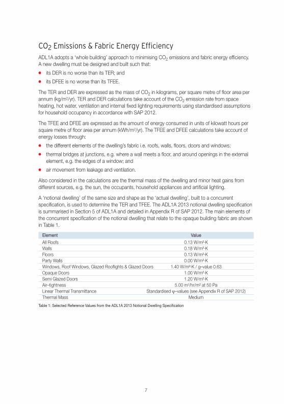
A ‘notional dwelling’ of the same size and shape as the ‘actual dwelling’, built to a concurrentspecification, is used to determine the TER and TFEE. The ADL1A 2013 notional dwelling specificationis summarised in Section 5 of ADL1A and detailed in Appendix R of SAP 2012. The main elements ofthe concurrent specification of the notional dwelling that relate to the opaque building fabric are shownin Table 1.
Element Value
All Roofs 0.13 W/m²·KWalls 0.18 W/m²·KFloors 0.13 W/m²·KParty Walls 0.00 W/m²·KWindows, Roof Windows, Glazed Rooflights & Glazed Doors 1.40 W/m²·K / g–value 0.63Opaque Doors 1.00 W/m²·KSemi Glazed Doors 1.20 W/m²·KAir–tightness 5.00 m3/hr/m² at 50 PaLinear Thermal Transmittance Standardised ψ–values (see Appendix R of SAP 2012)Thermal Mass Medium
Table 1: Selected Reference Values from the ADL1A 2013 Notional Dwelling Specification

8
Calculating the TERThe TER is calculated as follows. The CO2 emission rate from a notional dwelling of the same size andshape as the actual dwelling is calculated, using the notional building specification. The CO2 emissionrate from the proposed space heating and hot water (CH), pumps and fans (CPF) and internal lighting(CL) are calculated separately. The TER is then calculated using the following formula:
TER2013 = CH x FF + CPF + CL
where FF is the fuel factor as shown in Table 2:
Fuel Type Fuel Factor
Mains Gas 1.00LPG 1.06Oil 1.17B30K 1.00Grid Electricity 1.55Solid Mineral Fuel 1.35Solid Multi Fuel 1.00Any Fuel with CO2 Emission Factor Less than that of Mains Gas 1.00
Table 2: Fuel Factor for Different Fuel Types
For buildings containing multiple dwellings e.g. terraced houses or apartments, an optional methodmay be selected when calculating the TER for all dwellings in the building. If this method is adopted,the floor area weighted average of all individual TER’s of the dwellings contained within the largerbuilding can be calculated using the formula:
(TER1 x Floor Area1) + (TER2 x Floor Area2) + (TER3 x Floor Area3)
(Floor Area1 + Floor Area2 + Floor Area3)
Calculating the TFEEThe TFEE is calculated by determining the fabric energy efficiency from a notional dwelling of the samesize and shape as the actual dwelling, using the notional dwelling specification – but with a 15%relaxation of the resultant target in order to allow a degree of flexibility.
For buildings containing multiple dwellings, the same optional method for calculating the floor areaweighted average TER may be selected when calculating the TFEE for all dwellings in the building:
(TFEE1 x Floor Area1) + (TFEE2 x Floor Area2) + (TFEE3 x Floor Area3)
(Floor Area1 + Floor Area2 + Floor Area3)
Approved Document L1A – New Dwellings

9
Achieving the TER & TFEEThe pre–construction DER and DFEE calculations should be carried out and presented to the BCBalong with a list of specifications, so as to indicate that the dwelling, ‘as designed’, is compliant and togenerate a list of features critical to compliance.
The post–construction, or final, DER and DFEE are calculated using the performance standards of theactual dwelling. For the purpose of demonstrating compliance, the final DER and DFEE calculationsmust be based upon the dwelling ‘as built’ and must not only include any changes made to theperformance specification during construction, but also the assessed air–permeability, which isdetermined as follows:
� where the dwelling has been pressure tested, the assessed air–permeability is the measuredair–permeability;
� where the dwelling has not been tested, the assessed air–permeability is the average test resultobtained from other dwellings of the same dwelling type on the development, but increased by amargin of +2.0 m3/hr/m2 at 50 Pa; or
� on small developments (two units or less), where the builder has opted to avoid testing, theassessed air–permeability is 15 m3/hr/m2 at 50 Pa.
For buildings containing multiple dwellings, compliance may be achieved by demonstrating that either:
� the individual DER and DFEE for each dwelling are no worse than the corresponding TER andTFEE, respectively; or
� the average DER and DFEE for all dwellings are no worse than the corresponding TER and TFEE,respectively.
If the latter method is adopted, the floor area weighted average of all the individual DER’s and DFEE’sfor each dwelling contained within the larger building can be calculated using the formulae,respectively:
(DER1 x Floor Area1) + (DER2 x Floor Area2) + (DER3 x Floor Area3)
(Floor Area1 + Floor Area2 + Floor Area3)
(DFEE1 x Floor Area1) + (DFEE2 x Floor Area2) + (DFEE3 x Floor Area3)
(Floor Area1 + Floor Area2 + Floor Area3)
It is important to note that if the floor area weighted average method is adopted, it cannot be usedacross multiple separate buildings on a site and it is still necessary to provide information for eachindividual dwelling.
10
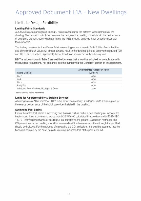
Limits to Design FlexibilityLimiting Fabric StandardsADL1A sets out area weighted limiting U–value standards for the different fabric elements of thedwelling. This provision is included to make the design of the dwelling robust should the performanceof one fabric element, upon which achieving the TFEE is highly dependent, fail or perform less wellthan expected.
The limiting U–values for the different fabric element types are shown in Table 3. It is of note that theuse of the limiting U–values will almost certainly result in the dwelling failing to achieve the required TERand TFEE, thus U–values, significantly better than those shown, are likely to be required.
NB The values shown in Table 3 are not the U–values that should be adopted for compliance withthe Building Regulations. For guidance, see the ‘Simplifying the Complex’ section of this document.
Area Weighted Average U–valueFabric Element (W/m2·K)
Roof 0.20Wall 0.30Floor 0.25Party Wall 0.20Windows, Roof Windows, Rooflights & Doors 2.00
Table 3: Limiting Fabric Parameters
Limits for Air–permeability & Building ServicesA limiting value of 10 m3/hr/m2 at 50 Pa is set for air–permeability. In addition, limits are also given forthe energy performance of the building services installed in the dwelling.
Swimming Pool BasinsIt must be noted that where a swimming pool basin is built as part of a new dwelling i.e. indoors, thebasin should have a U–value no worse than 0.25 W/m2·K, calculated in accordance with BS EN ISO13370 (Thermal performance of buildings. Heat transfer via the ground. Calculation methods). TheCO2 emissions for the dwelling should be assessed as if the basin was not there though the pool hallshould be included. For the purpose of calculating the CO2 emissions, it should be assumed that thefloor area covered by the basin has a U–value equivalent to that of the pool surround.
Approved Document L1A – New Dwellings
11
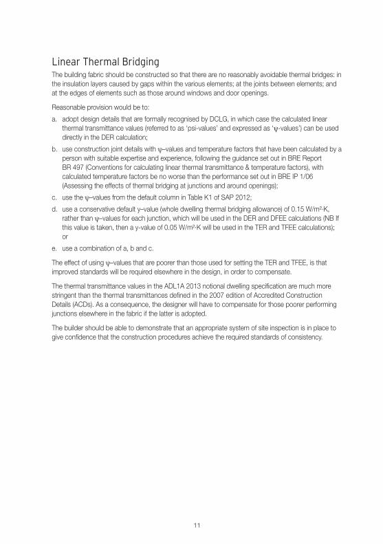
Linear Thermal BridgingThe building fabric should be constructed so that there are no reasonably avoidable thermal bridges: inthe insulation layers caused by gaps within the various elements; at the joints between elements; andat the edges of elements such as those around windows and door openings.
Reasonable provision would be to:
a. adopt design details that are formally recognised by DCLG, in which case the calculated linearthermal transmittance values (referred to as ‘psi-values’ and expressed as ‘ψ-values’) can be useddirectly in the DER calculation;
b. use construction joint details with ψ–values and temperature factors that have been calculated by aperson with suitable expertise and experience, following the guidance set out in BRE ReportBR 497 (Conventions for calculating linear thermal transmittance & temperature factors), withcalculated temperature factors be no worse than the performance set out in BRE IP 1/06(Assessing the effects of thermal bridging at junctions and around openings);
c. use the ψ–values from the default column in Table K1 of SAP 2012;
d. use a conservative default y–value (whole dwelling thermal bridging allowance) of 0.15 W/m²·K,rather than ψ–values for each junction, which will be used in the DER and DFEE calculations (NB Ifthis value is taken, then a y-value of 0.05 W/m²·K will be used in the TER and TFEE calculations);or
e. use a combination of a, b and c.
The effect of using ψ–values that are poorer than those used for setting the TER and TFEE, is thatimproved standards will be required elsewhere in the design, in order to compensate.
The thermal transmittance values in the ADL1A 2013 notional dwelling specification are much morestringent than the thermal transmittances defined in the 2007 edition of Accredited ConstructionDetails (ACDs). As a consequence, the designer will have to compensate for those poorer performingjunctions elsewhere in the fabric if the latter is adopted.
The builder should be able to demonstrate that an appropriate system of site inspection is in place togive confidence that the construction procedures achieve the required standards of consistency.
12
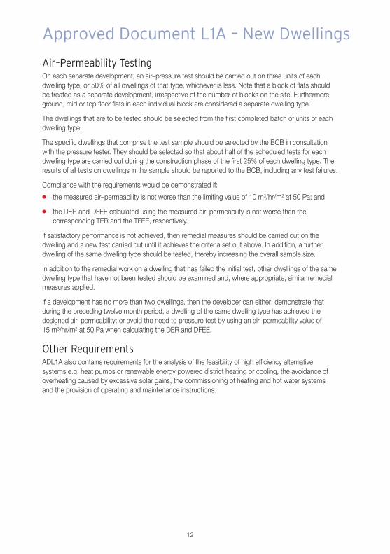
Air–Permeability TestingOn each separate development, an air–pressure test should be carried out on three units of eachdwelling type, or 50% of all dwellings of that type, whichever is less. Note that a block of flats shouldbe treated as a separate development, irrespective of the number of blocks on the site. Furthermore,ground, mid or top floor flats in each individual block are considered a separate dwelling type.
The dwellings that are to be tested should be selected from the first completed batch of units of eachdwelling type.
The specific dwellings that comprise the test sample should be selected by the BCB in consultationwith the pressure tester. They should be selected so that about half of the scheduled tests for eachdwelling type are carried out during the construction phase of the first 25% of each dwelling type. Theresults of all tests on dwellings in the sample should be reported to the BCB, including any test failures.
Compliance with the requirements would be demonstrated if:
� the measured air–permeability is not worse than the limiting value of 10 m3/hr/m2 at 50 Pa; and
� the DER and DFEE calculated using the measured air–permeability is not worse than thecorresponding TER and the TFEE, respectively.
If satisfactory performance is not achieved, then remedial measures should be carried out on thedwelling and a new test carried out until it achieves the criteria set out above. In addition, a furtherdwelling of the same dwelling type should be tested, thereby increasing the overall sample size.
In addition to the remedial work on a dwelling that has failed the initial test, other dwellings of the samedwelling type that have not been tested should be examined and, where appropriate, similar remedialmeasures applied.
If a development has no more than two dwellings, then the developer can either: demonstrate thatduring the preceding twelve month period, a dwelling of the same dwelling type has achieved thedesigned air–permeability; or avoid the need to pressure test by using an air–permeability value of15 m3/hr/m2 at 50 Pa when calculating the DER and DFEE.
Other RequirementsADL1A also contains requirements for the analysis of the feasibility of high efficiency alternativesystems e.g. heat pumps or renewable energy powered district heating or cooling, the avoidance ofoverheating caused by excessive solar gains, the commissioning of heating and hot water systemsand the provision of operating and maintenance instructions.
Approved Document L1A – New Dwellings

13
Simplifying the ComplexThe ADL1A 2013 notional dwelling specification provides a useful function in that it provides astraightforward elemental route to compliance. If the actual dwelling is built entirely to the notionaldwelling specification, it will meet the CO2 emissions and fabric energy efficiency targets, as well as thelimiting values for individual fabric elements and fixed building services.
Nonetheless, there is still huge scope for flexibility, should developers want it. Developers can, if theyprefer, choose to diverge from the ADL1A notional dwelling specification, so long as the dwelling ‘asbuilt’ achieves, or exceeds, the TER, TFEE and limiting values.
Indeed the ADL1A 2013 notional dwelling specification has been strengthened to deliver a 6%reduction in the CO2 emission rate across the new homes build mix relative to ADL2A 2010. Thisreduction is manifested in the ADL1A 2013 notional dwelling specification by much tougher linearthermal transmittance values and a lower air–tightness value.
At present, a set of standard details to achieve the new linear thermal transmittances (e.g. 2013 ACDs)does not exist and is probably unlikely to be developed by DCLG. Likewise, adopting anair–permeability rate of 5 m²/hr/m² at 50 Pa in DER and DFEE is a risk for developers. This wouldrequire the tested sample of dwellings to achieve 3 m3/hr/m² at 50 Pa. This is an onerous target andcurrent guidance is that such air–tight dwellings require mechanical ventilation with heat recoverysystems to be installed.
The most practical route forward for developers may well be to continue to work with anair–permeability target of 7 m3/hr/m² at 50 Pa and to continue to adopt the 2007 ACDs, whilstcompensating by adopting better fabric U–values than suggested by the ADL1A 2013 notionaldwelling specification.
Modelling carried out by Kingspan Insulation suggests that the values shown in Table 4 are the beststarting point U–values if adopting this latter approach.
U–valueElement (W/m2.K)
All Roofs 0.11Walls 0.16Floors 0.11
Table 4: Best Starting Point U-values
14
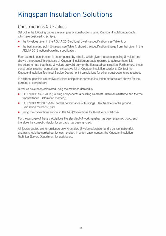
Constructions & U–valuesSet out in the following pages are examples of constructions using Kingspan Insulation products,which are designed to achieve:
� the U–values given in the ADL1A 2013 notional dwelling specification, see Table 1; or
� the best starting point U-values, see Table 4, should the specification diverge from that given in theADL1A 2013 notional dwelling specification.
Each example construction is accompanied by a table, which gives the corresponding U–values andshows the practical thicknesses of Kingspan Insulation products required to achieve them. It isimportant to note that these U–values are valid only for the illustrated construction. Furthermore, theseconstructions do not comprise an exhaustive list of Kingspan Insulation solutions. Contact theKingspan Insulation Technical Service Department if calculations for other constructions are required.
In addition, possible alternative solutions using other common insulation materials are shown for thepurpose of comparison.
U–values have been calculated using the methods detailed in:
� BS EN ISO 6946: 2007 (Building components & building elements. Thermal resistance and thermaltransmittance. Calculation method);
� BS EN ISO 13370: 1998 (Thermal performance of buildings. Heat transfer via the ground.Calculation methods); and
� using the conventions set out in BR 443 (Conventions for U–value calculations).
For the purpose of these calculations the standard of workmanship has been assumed good, andtherefore the correction factor for air gaps has been ignored.
All figures quoted are for guidance only. A detailed U–value calculation and a condensation riskanalysis should be carried out for each project. In which case, contact the Kingspan InsulationTechnical Service Department for assistance.
Kingspan Insulation Solutions
15
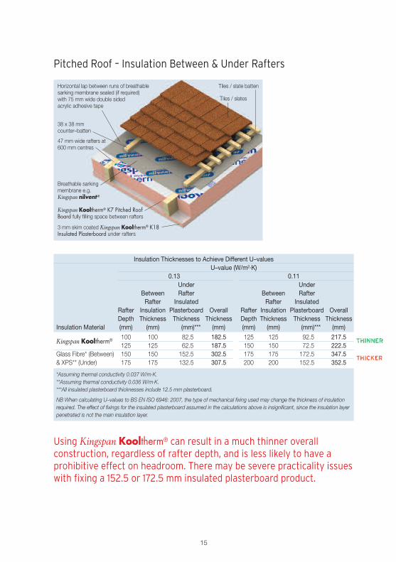
Horizontal lap between runs of breathablesarking membrane sealed (if required)with 75 mm wide double sidedacrylic adhesive tape
47 mm wide rafters at600 mm centres
Kingspan Kooltherm® K7 Pitched RoofBoard fully filling space between rafters
Tiles / slates
Tiles / slate batten
Breathable sarkingmembrane e.g.Kingspan nilvent®
38 x 38 mmcounter–batten
3 mm skim coated Kingspan Kooltherm® K18Insulated Plasterboard under rafters
Pitched Roof – Insulation Between & Under Rafters
Using Kingspan Kooltherm® can result in a much thinner overallconstruction, regardless of rafter depth, and is less likely to have aprohibitive effect on headroom. There may be severe practicality issueswith fixing a 152.5 or 172.5 mm insulated plasterboard product.
Insulation Thicknesses to Achieve Different U–valuesU–value (W/m2·K)
0.13 0.11Under Under
Between Rafter Between RafterRafter Insulated Rafter Insulated
Rafter Insulation Plasterboard Overall Rafter Insulation Plasterboard OverallDepth Thickness Thickness Thickness Depth Thickness Thickness Thickness
Insulation Material (mm) (mm) (mm)*** (mm) (mm) (mm) (mm)*** (mm)
Kingspan Kooltherm® 100 100 82.5 182.5 125 125 92.5 217.5125 125 62.5 187.5 150 150 72.5 222.5
Glass Fibre* (Between) 150 150 152.5 302.5 175 175 172.5 347.5& XPS** (Under) 175 175 132.5 307.5 200 200 152.5 352.5
*Assuming thermal conductivity 0.037 W/m·K.**Assuming thermal conductivity 0.036 W/m·K.***All insulated plasterboard thicknesses include 12.5 mm plasterboard.
NB When calculating U–values to BS EN ISO 6946: 2007, the type of mechanical fixing used may change the thickness of insulationrequired. The effect of fixings for the insulated plasterboard assumed in the calculations above is insignificant, since the insulation layerpenetrated is not the main insulation layer.
16
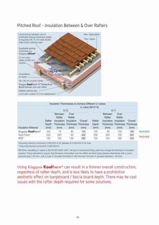
Pitched Roof – Insulation Between & Over Rafters
Using Kingspan Kooltherm® can result in a thinner overall construction,regardless of rafter depth, and is less likely to have a prohibitiveaesthetic effect on bargeboard / fascia board depth. There may be costissues with the rafter depth required for some solutions.
Insulation Thicknesses to Achieve Different U–valuesU–value (W/m2·K)
0.13 0.11Between Over Between OverRafter Rafter Rafter Rafter
Rafter Insulation Insulation Overall Rafter Insulation Insulation OverallDepth Thickness Thickness Thickness Depth Thickness Thickness Thickness
Insulation Material (mm) (mm) (mm) (mm) (mm) (mm) (mm) (mm)
Kingspan Kooltherm® 100 75 80 155 100 80 100 180Rock Fibre* 220 220 80 300 250 250 100 350XPS** 150 150 130 280 150 150 180 330
*Assuming thermal conductivity 0.038 W/m·K for between & 0.036 W/m·K for over.**Assuming thermal conductivity 0.036 W/m·K.
NB When calculating U–values to BS EN ISO 6946: 2007, the type of mechanical fixing used may change the thickness of insulationrequired. These calculations assume that the layers of insulation over the rafters are fixed using stainless steel fixings with a cross–sectional area 7.45 mm2, with 8.3 per m2 (insulant thickness 61–80 mm) and 10.0 per m2 (insulant thickness > 80 mm).
Horizontal lap between runs ofbreathable sarking membrane sealed(if required) with 75 mm wide doublesided acrylic adhesive tape
47 mm widerafters at 600 mmcentres
Kingspan Kooltherm® K7 Pitched RoofBoard between and over rafters
Tiles / slates
Tiles / slate batten
Nailable sarking clips
Breathable sarkingmembrane e.g.Kingspan nilvent®
3 mm skim coated 12.5 mm plasterboard
38 x 38 mm counter–batten
Unventilatedair space
17
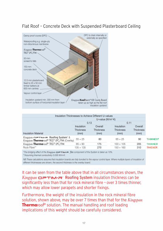
Flat Roof – Concrete Deck with Suspended Plasterboard Ceiling
It can be seen from the table above that in all circumstances shown, theKingspan Roofing System insulation thickness can besignificantly less than that for rock mineral fibre – over 3 times thinner,which may allow lower parapets and shorter fixings.
Furthermore, the weight of the insulation in the rock mineral fibresolution, shown above, may be over 7 times than that for the KingspanThermaroof® solution. The manual handling and roof loadingimplications of this weight should be carefully considered.
Damp proof course (DPC) DPC to drain internally orexternally as specified
Waterproofing e.g. single–plynon–bituminous membrane
Vapour control layer
Kingspan Thermaroof®
TR27 LPC/FM
Insulation upstand min. 300 mm frombottom surface of horizontal insulation layer
12.5 mm plasterboardfixed to 25 x 50 mmtimber battens at600 mm centres
KingspanKooltherm® K8 Cavity Boardtaken up as high as the flat roof
insulation upstand
150 mmconcrete deck
50 mmscreed to falls
Insulation Thicknesses to Achieve Different U–valuesU–value (W/m2·K)
0.13 0.11Insulation Overall Insulation OverallThickness Thickness Thickness Thickness
Insulation Material (mm) (mm) (mm) (mm)
Kingspan Roofing System* &55 + 25 80 65 + 25 90Kingspan Thermaroof® TR27 LPC/FM (Overlay)
Kingspan Thermaroof® TR27 LPC/FM 85 + 90 175 100 + 105 205Rock Fibre** 135 + 135 270 150 + 160 310
*The bridging effect of the Kingspan flex component of the System is taken as 10%.**Assuming thermal conductivity 0.038 W/m·K.
NB These calculations assume that insulation boards are fully bonded to the vapour control layer. Where multiple layers of insulation ofdifferent thicknesses are shown, the second thickness is the overlay board.
18
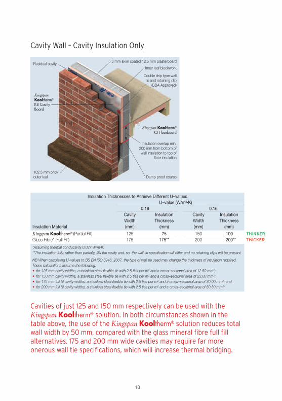
Cavity Wall – Cavity Insulation Only
Insulation Thicknesses to Achieve Different U–valuesU–value (W/m2·K)
0.18 0.16Cavity Insulation Cavity InsulationWidth Thickness Width Thickness
Insulation Material (mm) (mm) (mm) (mm)
Kingspan Kooltherm® (Partial Fill) 125 75 150 100Glass Fibre* (Full Fill) 175 175** 200 200**
*Assuming thermal conductivity 0.037 W/m·K.**The insulation fully, rather than partially, fills the cavity and, so, the wall tie specification will differ and no retaining clips will be present.
NB When calculating U–values to BS EN ISO 6946: 2007, the type of wall tie used may change the thickness of insulation required.These calculations assume the following:• for 125 mm cavity widths, a stainless steel flexible tie with 2.5 ties per m2 and a cross–sectional area of 12.50 mm2;• for 150 mm cavity widths, a stainless steel flexible tie with 2.5 ties per m2 and a cross–sectional area of 23.00 mm2;• for 175 mm full fill cavity widths, a stainless steel flexible tie with 2.5 ties per m2 and a cross–sectional area of 30.00 mm2; and• for 200 mm full fill cavity widths, a stainless steel flexible tie with 2.5 ties per m2 and a cross–sectional area of 60.80 mm2;
3 mm skim coated 12.5 mm plasterboard
Inner leaf blockworkResidual cavity
Double drip type walltie and retaining clip
(BBA Approved)
Kingspan Kooltherm®
K3 Floorboard
102.5 mm brickouter leaf
KingspanKooltherm®
K8 CavityBoard
Damp proof course
Insulation overlap min.200 mm from bottom ofwall insulation to top of
floor insulation
Cavities of just 125 and 150 mm respectively can be used with theKingspan Kooltherm® solution. In both circumstances shown in thetable above, the use of the Kingspan Kooltherm® solution reduces totalwall width by 50 mm, compared with the glass mineral fibre full fillalternatives. 175 and 200 mm wide cavities may require far moreonerous wall tie specifications, which will increase thermal bridging.
19
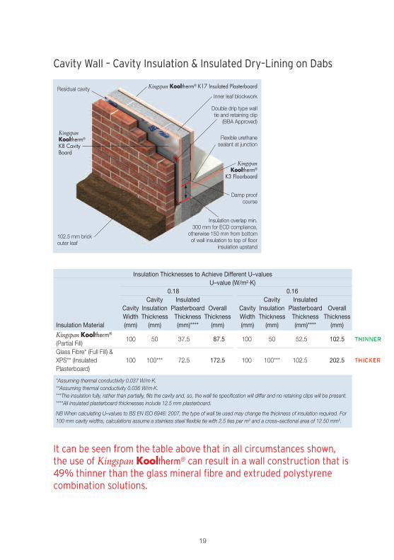
Cavity Wall – Cavity Insulation & Insulated Dry–Lining on Dabs
Residual cavity
Double drip type walltie and retaining clip
(BBA Approved)
102.5 mm brickouter leaf
Insulation overlap min.300 mm for ECD compliance,
otherwise 150 mm from bottomof wall insulation to top of floor
insulation upstand
Kingspan Kooltherm® K17 Insulated Plasterboard
Inner leaf blockwork
Flexible urethanesealant at junction
KingspanKooltherm®
K8 CavityBoard
KingspanKooltherm®
K3 Floorboard
Damp proofcourse
Insulation Thicknesses to Achieve Different U–valuesU–value (W/m2·K)
0.18 0.16Cavity Insulated Cavity Insulated
Cavity Insulation Plasterboard Overall Cavity Insulation Plasterboard OverallWidth Thickness Thickness Thickness Width Thickness Thickness Thickness
Insulation Material (mm) (mm) (mm)**** (mm) (mm) (mm) (mm)**** (mm)
Kingspan Kooltherm®100 50 37.5 87.5 100 50 52.5 102.5
(Partial Fill)Glass Fibre* (Full Fill) &XPS** (Insulated 100 100*** 72.5 172.5 100 100*** 102.5 202.5Plasterboard)
*Assuming thermal conductivity 0.037 W/m·K.**Assuming thermal conductivity 0.036 W/m·K.***The insulation fully, rather than partially, fills the cavity and, so, the wall tie specification will differ and no retaining clips will be present.****All insulated plasterboard thicknesses include 12.5 mm plasterboard.
NB When calculating U–values to BS EN ISO 6946: 2007, the type of wall tie used may change the thickness of insulation required. For100 mm cavity widths, calculations assume a stainless steel flexible tie with 2.5 ties per m2 and a cross–sectional area of 12.50 mm2.
It can be seen from the table above that in all circumstances shown,the use of Kingspan Kooltherm® can result in a wall construction that is49% thinner than the glass mineral fibre and extruded polystyrenecombination solutions.
20
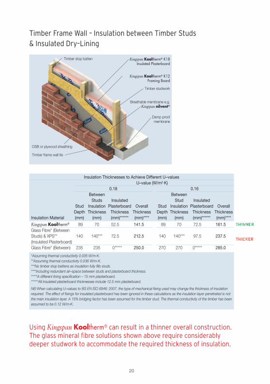
Timber Frame Wall – Insulation between Timber Studs& Insulated Dry–Lining
Kingspan Kooltherm® K18Insulated Plasterboard
Kingspan Kooltherm® K12Framing Board
Timber studwork
Breathable membrane e.g.Kingspan nilvent®
Damp proofmembrane
Timber stop batten
Timber frame wall tie
OSB or plywood sheathing
Insulation Thicknesses to Achieve Different U–valuesU–value (W/m2·K)
0.18 0.16Between BetweenStuds Insulated Stud Insulated
Stud Insulation Plasterboard Overall Stud Insulation Plasterboard OverallDepth Thickness Thickness Thickness Depth Thickness Thickness Thickness
Insulation Material (mm) (mm) (mm)****** (mm)**** (mm) (mm) (mm)****** (mm)****
Kingspan Kooltherm® 89 70 52.5 141.5 89 70 72.5 161.5Glass Fibre* (BetweenStuds) & XPS** 140 140*** 72.5 212.5 140 140*** 97.5 237.5(Insulated Plasterboard)Glass Fibre* (Between) 235 235 0***** 250.0 270 270 0***** 285.0
*Assuming thermal conductivity 0.035 W/m·K.**Assuming thermal conductivity 0.036 W/m·K.***No timber stop battens as insulation fully fills studs.****Including redundant air–space between studs and plasterboard thickness.*****A different lining specification – 15 mm plasterboard.******All insulated plasterboard thicknesses include 12.5 mm plasterboard.
NB When calculating U–values to BS EN ISO 6946: 2007, the type of mechanical fixing used may change the thickness of insulationrequired. The effect of fixings for insulated plasterboard has been ignored in these calculations as the insulation layer penetrated is notthe main insulation layer. A 15% bridging factor has been assumed for the timber stud. The thermal conductivity of the timber has beenassumed to be 0.12 W/m·K.
Using Kingspan Kooltherm® can result in a thinner overall construction.The glass mineral fibre solutions shown above require considerablydeeper studwork to accommodate the required thickness of insulation.
21
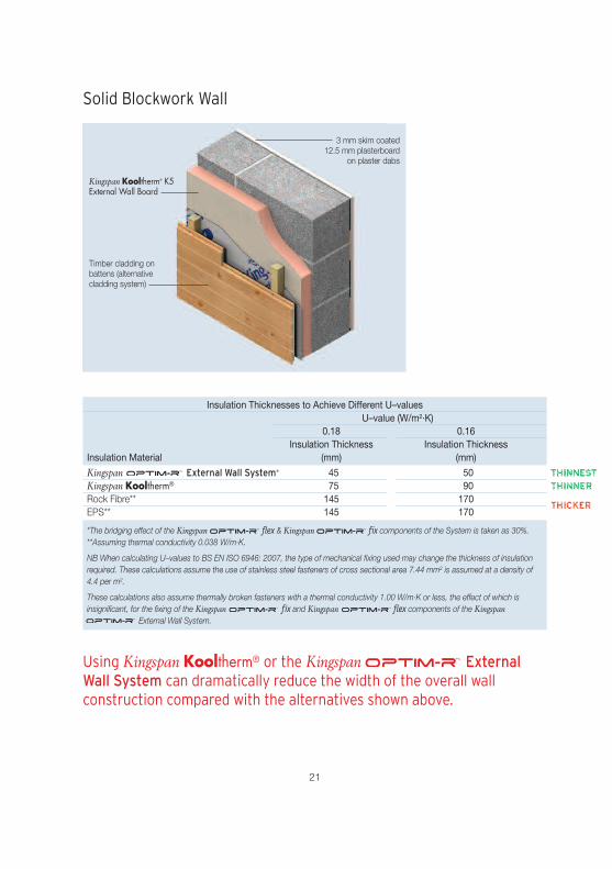
Solid Blockwork Wall
3 mm skim coated12.5 mm plasterboard
on plaster dabs
Kingspan Kooltherm® K5External Wall Board
Timber cladding onbattens (alternativecladding system)
Insulation Thicknesses to Achieve Different U–valuesU–value (W/m2·K)
0.18 0.16Insulation Thickness Insulation Thickness
Insulation Material (mm) (mm)
Kingspan External Wall System* 45 50Kingspan Kooltherm® 75 90Rock Fibre** 145 170EPS** 145 170
*The bridging effect of the Kingspan flex & Kingspan fix components of the System is taken as 30%.**Assuming thermal conductivity 0.038 W/m·K.
NB When calculating U–values to BS EN ISO 6946: 2007, the type of mechanical fixing used may change the thickness of insulationrequired. These calculations assume the use of stainless steel fasteners of cross sectional area 7.44 mm2 is assumed at a density of4.4 per m2.
These calculations also assume thermally broken fasteners with a thermal conductivity 1.00 W/m·K or less, the effect of which isinsignificant, for the fixing of the Kingspan fix and Kingspan flex components of the Kingspan
External Wall System.
Using Kingspan Kooltherm® or the Kingspan ExternalWall System can dramatically reduce the width of the overall wallconstruction compared with the alternatives shown above.

22
Rainscreen Cladding on Steel Frame
Non−combustible substrate– calcium silicate board
Kingspan Kooltherm®
K15 Rainscreen Board
Proprietary fixing rail
Cladding panel
Insulation Thicknesses to Achieve Different U–valuesU–value (W/m2·K)
0.18 0.16Insulation Overall Insulation OverallThickness Thickness Thickness Thickness
Insulation Material (mm) (mm) (mm) (mm)
Kingspan Rainscreen System* 50 + 50 100 60 + 60 120Kingspan Kooltherm® 80 + 80 160 90 + 100 190Rock Fibre** 130 + 140 270 160 + 160 320
*The bridging effect of the Kingspan flex & Kingspan fix components of the System is taken as 30%.**Assuming thermal conductivity 0.035 W/m·K.
NB Where multiple layers of insulation of different thicknesses are shown, the second thickness is the outer layer. When calculatingU–values to BS EN ISO 6946: 2007, the type of discrete ‘helping hand’ bracket may change the thickness of insulation required.These calculations assume carbon steel fasteners of cross–sectional area 16.98 mm2 at a density of 3.13 per m2.
Using Kingspan Kooltherm® or the Kingspan RainscreenSystem solution can result in a dramatically thinner overall construction.The rock mineral fibre solutions shown above require considerablydeeper discrete helping hand brackets to accommodate the requiredthickness of insulation.
23
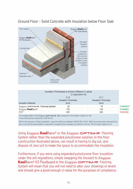
Ground Floor – Solid Concrete with Insulation below Floor Slab
Insulation Thicknesses to Achieve Different U–valuesU–value (W/m2·K)
0.13 0.11Insulation Thickness Insulation Thickness
Insulation Material (mm) (mm)
Kingspan Flooring System* 55 70Kingspan Kooltherm® 125 140EPS** 225 265
*The bridging effect of the Kingspan flex component of the System is taken as 15%.**Assuming thermal conductivity 0.038 W/m·K.
NB For the purposes of these calculations, using the method as detailed in BS EN ISO 13370: 1998, the soil has been assumed to beclay or silt, and the wall insulation is assumed to overlap the floor insulation by minimum 150 mm. The P/A ratio is taken as 0.5.
Using Kingspan Kooltherm® or the Kingspan FlooringSystem rather than the expanded polystyrene solution, in the floorconstruction illustrated above, can result in having to dig out, anddispose of, less soil to make the space to accommodate the insulation.
Furthermore, if you were using expanded polystyrene floor insulationunder the old regulations, simply swapping the insulant to KingspanKooltherm® K3 Floorboard or the Kingspan FlooringSystem will mean that you will not need to alter your drawings or levelsand should give a good enough U–value for the purposes of compliance.
Concrete slab
Floor screed Kingspan Kooltherm®
K8 Cavity Board
HardcoreSeparation layer
Kingspan Kooltherm®
K3 FloorboardPerimeterinsulationupstand
Damp proofmembrane
Insulationoverlap min.
150 mm frombottom of wall
insulation to topof insulation
upstand

Customer ServiceTel: 01544 388 601Fax: 01544 388 888email: [email protected]
Literature & SamplesTel: 01544 387 384Fax: 01544 387 484email: [email protected]
Tapered RoofingTel: 01544 387 383Fax: 01544 387 483email: [email protected]
Technical AdviceTel: 01544 387 382Fax: 01544 387 482email: [email protected]
General EnquiriesTel: 01544 388 601Fax: 01544 388 888email: [email protected]
Kingspan Insulation LtdPembridge, Leominster, Herefordshire HR6 9LA, UK
www.kingspaninsulation.co.uk
® Kingspan, Kooltherm, Nilvent, Thermaroof and the Lion Device are Registered Trademarks of the Kingspan Group plc inthe UK and other countries. All rights reserved.
TM Optim-R is a Trademark of the Kingspan Group plc.Kingspan Insulation Ltd. Registered in England & Wales, No. 01882722. Registered Office: Pembridge, Leominster, Herefordshire HR6 9LA UK.