building low cost autonomous robots - wordpress.com · building low cost autonomous robots ......
TRANSCRIPT
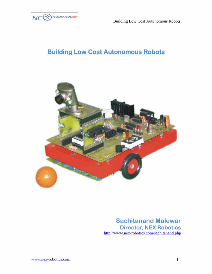
Building Low Cost Autonomous Robots
www.nex-robotics.com
Building Low Cost Autonomous Robots
Sachitanand Malewar
Director, NEX Robotics http://www.nex-robotics.com/sachitanand.php
1
Building Low Cost Autonomous Robots
www.nex-robotics.com
In this series of tutorials we are going to learn how to construct autonomous robot. Autonomous robots are designed for lots of applications so in order to restrict ourselves to a basic design we will take machine for Vertigo in Techfest 2008 as a case study. Rules for the competition is available at http://techfest.org/competitions/xtreme-machines/vertigo/ Any autonomous robot consists of following essential parts.
1. Robot Chassis and actuators Includes wheeled or any type of chassis with all the necessary actuators fitted on the chassis to achieve desired goal.
2. Electronics Electronics includes Sensors, motion control circuits, power management system etc.
3. Power pack Usually battery pack consisting of Lead acid, Nickel cadmium, Nickel metal hydride or Lithium batteries is used.
4. Intelligence This is the most important part of the autonomous robots. Usually intelligence is achieved by using microcontroller.
First step in making an autonomous robot is to chalk out what tasks we are expecting the robot to perform. After gauging these we get a vague idea about the design and appearance of the robot. Expectations:
1. Dimensions (In this case robot should fit within cube of 20cm) 2. Robot should be completely autonomous, self contained and should not
communicate with an external agency in any way. 3. Robot is not allowed to dismember itself or leave parts on any part of the
arena 4. Onboard self contained power 5. Life expectancy of the robot
Life expectancy of the robot is number of hours it is expected that robot will perform flawlessly) If we consider the trial runs practice sessions and competition runs robots is not functional for more than few hours. Hence we don’t need to seriously over design robots parts. This saves lots of time, effort and money.
6. Elegant well finished looks. Tasks:
1. To sense white line on black surface and navigate autonomously along the game field using grid of white line.
2. To accept block from the manual machine and throw that block in to the pit.
2
Building Low Cost Autonomous Robots
www.nex-robotics.com
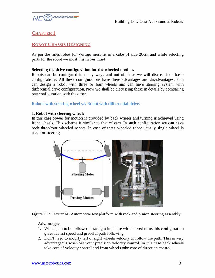
CHAPTER 1 ROBOT CHASSIS DESIGNING As per the rules robot for Vertigo must fit in a cube of side 20cm and while selecting parts for the robot we must this in our mind. Selecting the drive configuration for the wheeled motion: Robots can be configured in many ways and out of these we will discuss four basic configurations. All these configurations have there advantages and disadvantages. You can design a robot with three or four wheels and can have steering system with differential drive configuration. Now we shall be discussing these in details by comparing one configuration with the other. Robots with steering wheel v/s Robot with differential drive. 1. Robot with steering wheel: In this case power for motion is provided by back wheels and turning is achieved using front wheels. This scheme is similar to that of cars. In such configuration we can have both three/four wheeled robots. In case of three wheeled robot usually single wheel is used for steering.
Figure 1.1: Dexter 6C Automotive test platform with rack and pinion steering assembly
Advantages: 1. When path to be followed is straight in nature with curved turns this configuration
gives fastest speed and graceful path following. 2. Don’t need to modify left or right wheels velocity to follow the path. This is very
advantageous when we want precision velocity control. In this case back wheels take care of velocity control and front wheels take care of direction control.
3

Building Low Cost Autonomous Robots
www.nex-robotics.com
Disadvantages: 1. It will not able to take very sharp turns. Hence it is difficult to move robot on the
grid of lines. 2. Little bit difficult to make. 3. Front wheels will need position feedback to control turning control. 4. Becomes expensive to make.
2. Robot with differential drive: In the differential drive left and right wheel are powered independently. Hence it is called as differential drive. This is the most popular drive configuration among the robotics hobbyists.
Figure 1.2: Robot with differential drive (left and right wheels are powered independently
Figure: Zero turning radius can be achieved using differential drive
Advantages: 1. Zero turning radius: This is the most important advantage of the differential drive.
In the differential drive as left and right wheel are independent if left wheel is rotated in anticlockwise and right wheel is turned clockwise robot will take turn in the left direction with zero turning radius.
2. Easy to move when path to be followed is contoured and zigzag in nature. E.g. navigating along the maze of lines.
4
Building Low Cost Autonomous Robots
www.nex-robotics.com
Disadvantages: 1. If we want to move along curved path we have to control left and right motor’s
velocity independently. Hence precision velocity control becomes difficult as actual velocity of the robot will be average of the both wheels.
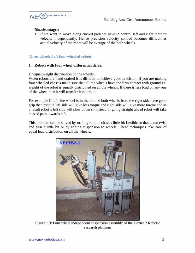
Three wheeled v/s four wheeled robots 1. Robots with four wheel differential drive: Unequal weight distribution on the wheels: When robots are hand crafted it is difficult to achieve good precision. If you are making four wheeled chassis make sure that all the wheels have the firm contact with ground i.e. weight of the robot is equally distributed on all the wheels. If there is less load on any one of the wheel then it will transfer less torque. For example if left side wheel is in the air and both wheels from the right side have good grip then robot’s left side will give less torque and right side will give more torque and as a result robot’s left side will slow down so instead of going straight ahead robot will take curved path towards left. This problem can be solved by making robot’s chassis little bit flexible so that it can twist and turn a little bit or by adding suspension to wheels. These techniques take care of equal load distribution on all the wheels.
Figure 1.3: Four wheel independent suspension assembly of the Dexter 2 Robotic
research platform
5
Building Low Cost Autonomous Robots
www.nex-robotics.com
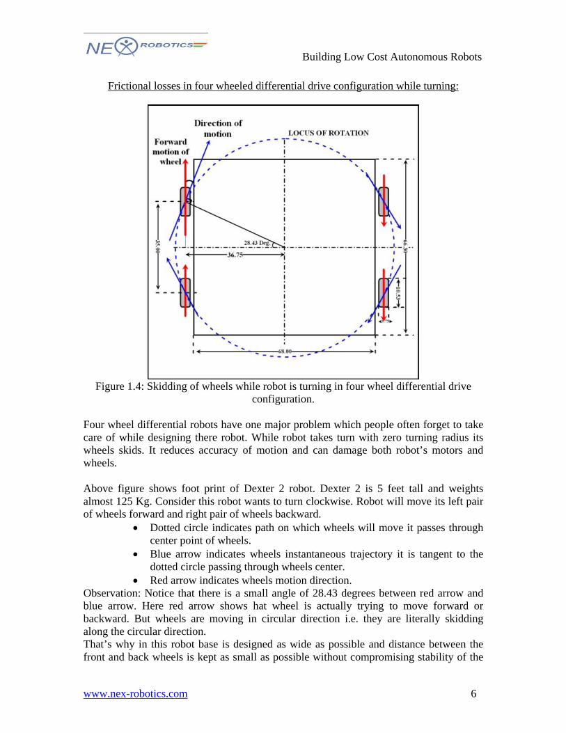
Frictional losses in four wheeled differential drive configuration while turning:
Figure 1.4: Skidding of wheels while robot is turning in four wheel differential drive
configuration. Four wheel differential robots have one major problem which people often forget to take care of while designing there robot. While robot takes turn with zero turning radius its wheels skids. It reduces accuracy of motion and can damage both robot’s motors and wheels. Above figure shows foot print of Dexter 2 robot. Dexter 2 is 5 feet tall and weights almost 125 Kg. Consider this robot wants to turn clockwise. Robot will move its left pair of wheels forward and right pair of wheels backward.
• Dotted circle indicates path on which wheels will move it passes through center point of wheels.
• Blue arrow indicates wheels instantaneous trajectory it is tangent to the dotted circle passing through wheels center.
• Red arrow indicates wheels motion direction. Observation: Notice that there is a small angle of 28.43 degrees between red arrow and blue arrow. Here red arrow shows hat wheel is actually trying to move forward or backward. But wheels are moving in circular direction i.e. they are literally skidding along the circular direction. That’s why in this robot base is designed as wide as possible and distance between the front and back wheels is kept as small as possible without compromising stability of the
6
Building Low Cost Autonomous Robots
www.nex-robotics.com
robot. If distance between robot’s front and back wheel is further increased then this angle will increase and will cause large frictional losses. If this angle is increased above 45 degrees it is very likely that robot will not be able to rotate with zero turning radius because motors will not be able to overcome friction due to skidding. 2. Robots with three wheel differential drive:
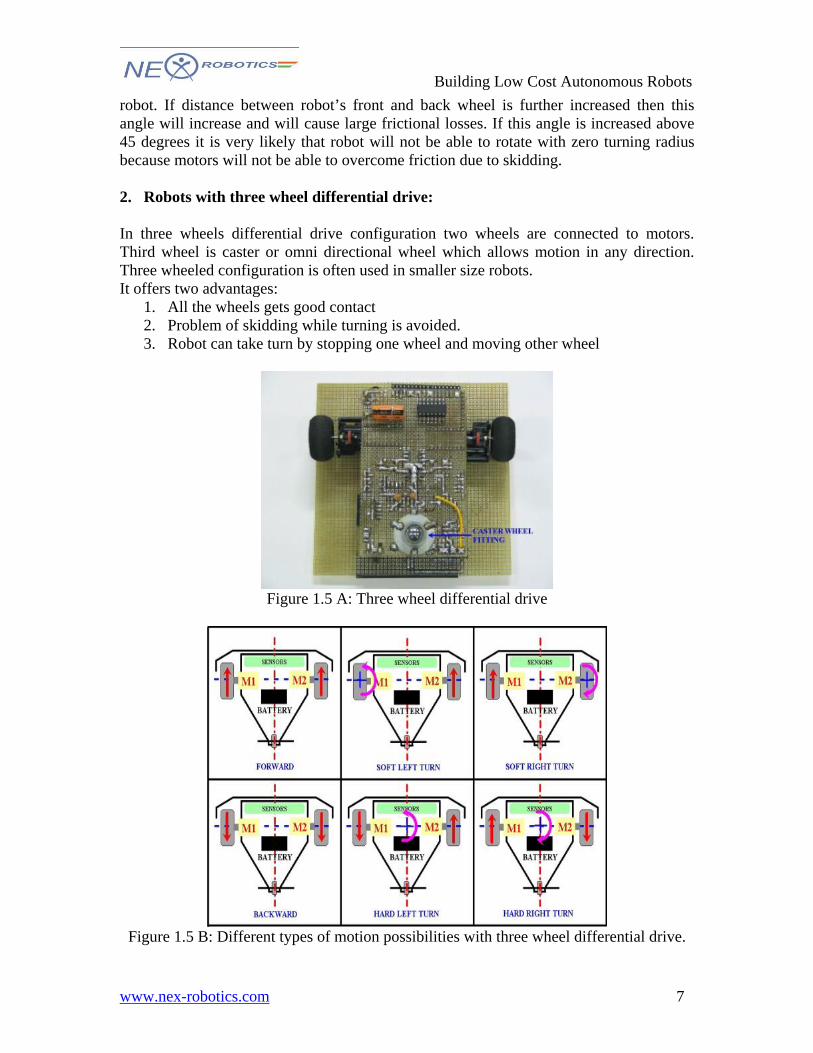
In three wheels differential drive configuration two wheels are connected to motors. Third wheel is caster or omni directional wheel which allows motion in any direction. Three wheeled configuration is often used in smaller size robots. It offers two advantages:
1. All the wheels gets good contact 2. Problem of skidding while turning is avoided. 3. Robot can take turn by stopping one wheel and moving other wheel
Figure 1.5 A: Three wheel differential drive
Figure 1.5 B: Different types of motion possibilities with three wheel differential drive.
7
Building Low Cost Autonomous Robots
www.nex-robotics.com
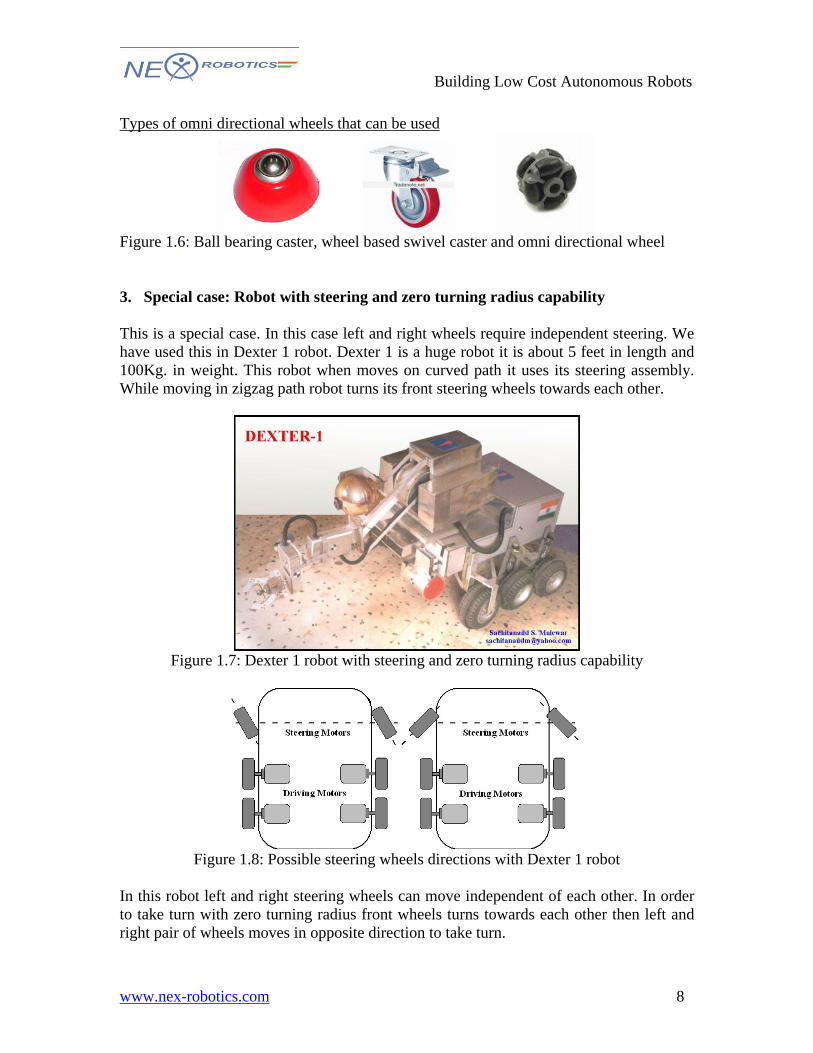
Types of omni directional wheels that can be used
Figure 1.6: Ball bearing caster, wheel based swivel caster and omni directional wheel 3. Special case: Robot with steering and zero turning radius capability This is a special case. In this case left and right wheels require independent steering. We have used this in Dexter 1 robot. Dexter 1 is a huge robot it is about 5 feet in length and 100Kg. in weight. This robot when moves on curved path it uses its steering assembly. While moving in zigzag path robot turns its front steering wheels towards each other.
Figure 1.7: Dexter 1 robot with steering and zero turning radius capability
Figure 1.8: Possible steering wheels directions with Dexter 1 robot
In this robot left and right steering wheels can move independent of each other. In order to take turn with zero turning radius front wheels turns towards each other then left and right pair of wheels moves in opposite direction to take turn.
8
Building Low Cost Autonomous Robots
www.nex-robotics.com
CHASSIS DESIGN: Before we start chassis fabrication let us chalk out few design considerations
• Payload considerations: Robot is supposed to carry a 10 cm cube weighting approximately 100gms.
• Size limitations:
It should fit within 20cm cube at the beginning of the game.
• Motion constrains It is suppose to move on grid of white lines. This means robot have to take frequent turns with zero turning radius.
• Sensing requirement:
Robot has to move along the grid so it should have sensors to sense grid of white lines.
• Additional actuators requirement:
Robot has to throw this 10cm cube in the pit. It should have some mechanism to unload this cube in to the pit.
• Power requirement: Robot chassis should have space for the battery.
Conclusions from above design considerations:
1. As robot is supposed to carry very light weight payload and it should also fit in the 20cm cube it will be a light weight robot.
2. It has to move on grid of white lines. This will require zero turning radius hence differential drive is preferred.
3. As it is light weight robot to keep design simple and costs low we are going to use three wheeled chassis.
4. White line sensors must be mounted at proper place in order to make motion simple and accurate. We will discuss this in next session.
5. We will require some kind of actuator at top for throwing ball in to the pit. 6. Space for the battery should be provided. Battery must be as near to ground as
possible to make stable design.
9
Building Low Cost Autonomous Robots
www.nex-robotics.com
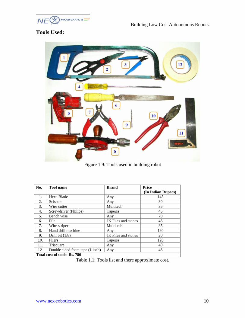
Tools Used:
Figure 1.9: Tools used in building robot
No. Tool name Brand Price
(In Indian Rupees) 1. Hexa Blade Any 145 2. Scissors Any 30 3. Wire cutter Multitech 35 4. Screwdriver (Philips) Taperia 45 5. Bench wise Any 70 6. File JK Files and stones 45 7. Wire striper Multitech 35 8. Hand drill machine Any 130 9. Drill bit (1/8) JK Files and stones 20
10. Pliers Taperia 120 11. Trisquare Any 40 12. Double sided foam tape (1 inch) Any 45
Total cost of tools: Rs. 780 Table 1.1: Tools list and there approximate cost.
10
Building Low Cost Autonomous Robots
www.nex-robotics.com
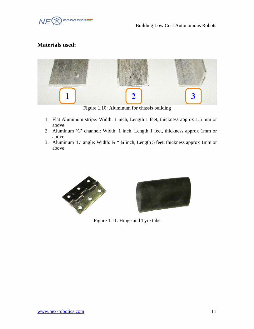
Materials used:
Figure 1.10: Aluminum for chassis building
1. Flat Aluminum stripe: Width: 1 inch, Length 1 feet, thickness approx 1.5 mm or
above 2. Aluminum ‘C’ channel: Width: 1 inch, Length 1 feet, thickness approx 1mm or
above 3. Aluminum ‘L’ angle: Width: ¾ * ¾ inch, Length 5 feet, thickness approx 1mm or
above
Figure 1.11: Hinge and Tyre tube
11
Building Low Cost Autonomous Robots
www.nex-robotics.com
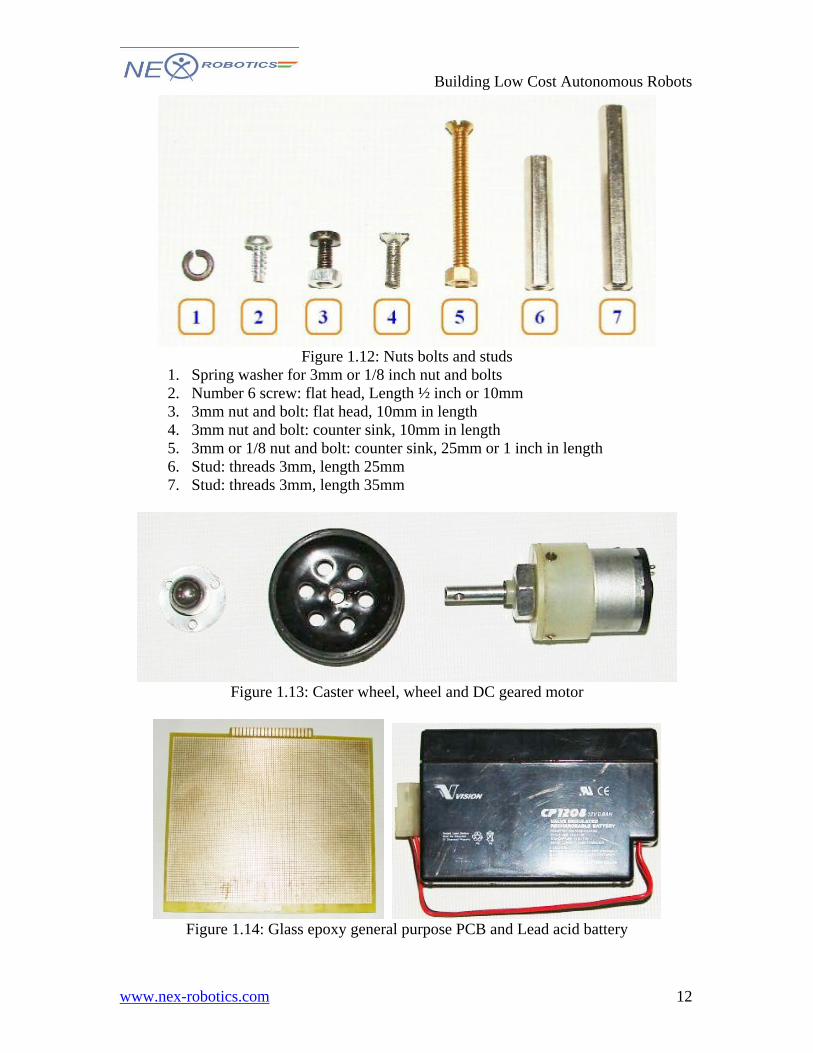
Figure 1.12: Nuts bolts and studs
1. Spring washer for 3mm or 1/8 inch nut and bolts 2. Number 6 screw: flat head, Length ½ inch or 10mm 3. 3mm nut and bolt: flat head, 10mm in length 4. 3mm nut and bolt: counter sink, 10mm in length 5. 3mm or 1/8 nut and bolt: counter sink, 25mm or 1 inch in length 6. Stud: threads 3mm, length 25mm 7. Stud: threads 3mm, length 35mm
Figure 1.13: Caster wheel, wheel and DC geared motor
Figure 1.14: Glass epoxy general purpose PCB and Lead acid battery
12
Building Low Cost Autonomous Robots
www.nex-robotics.com
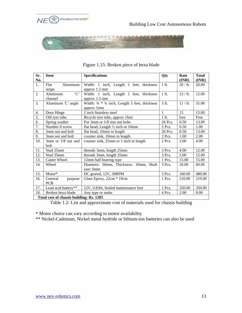
Figure 1.15: Broken piece of hexa blade Sr. No.
Item Specifications Qty Rate (INR)
Total (INR)
1. Flat Aluminum stripe
Width: 1 inch, Length 1 feet, thickness approx 1.5 mm
1 ft. 20 / ft. 20.00
2. Aluminum ‘C’ channel
Width: 1 inch, Length 1 feet, thickness approx 1.5 mm
1 ft. 12 / ft. 12.00
3. Aluminum ‘L’ angle Width: ¾ * ¾ inch, Length 5 feet, thickness approx 1mm
5 ft. 11 / ft. 55.00
4. Door Hinge 2 inch Stainless steel 1 15 15.00 5. Old tyer tube Bicycle tyer tube, approx 1feet 1 ft. free Free 6. Spring washer For 3mm or 1/8 size nut bolts 26 Pcs. 0.50 13.00 7. Number 6 screw flat head, Length ½ inch or 10mm 2 Pcs. 0.50 1.00 8. 3mm nut and bolt flat head, 10mm in length 26 Pcs. 0.50 13.00 9. 3mm nut and bolt counter sink, 10mm in length 2 Pcs. 1.00 2.00 10. 3mm or 1/8 nut and
bolt counter sink, 25mm or 1 inch in length 2 Pcs. 2.00 4.00
11. Stud 25mm threads 3mm, length 25mm 3 Pcs. 4.00 12.00 12. Stud 35mm threads 3mm, length 35mm 3 Pcs. 5.00 15.00 13. Caster Wheel 12mm ball bearing type 1 Pcs. 15.00 15.00 14. Wheel Diameter: 50mm, Thickness: 10mm, Shaft
size: 6mm 3 Pcs. 20.00 60.00
15. Motor* DC geared, 12V, 30RPM 3 Pcs. 160.00 480.00 16. General purpose
PCB Glass Epoxy, 22cm * 19cm 1 Pcs. 210.00 210.00
17. Lead acid battery** 12V, 0.8Ah, Sealed maintenance free 1 Pcs. 350.00 350.00 18. Broken hexa blade Any type or make 4 Pcs. 2.00 8.00
Total cost of chassis building: Rs. 1285 Table 1.2: List and approximate cost of materials used for chassis building
* Motor choice can vary according to motor availability ** Nickel-Cadmium, Nickel metal hydride or lithium-ion batteries can also be used
13
Building Low Cost Autonomous Robots
www.nex-robotics.com
FABRICATION OF MACHINES CHASSIS 1. Assembling the robot base
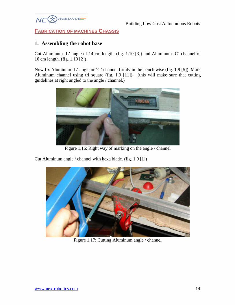
Cut Aluminum ‘L’ angle of 14 cm length. (fig. 1.10 [3]) and Aluminum ‘C’ channel of 16 cm length. (fig. 1.10 [2]) Now fix Aluminum ‘L’ angle or ‘C’ channel firmly in the bench wise (fig. 1.9 [5]). Mark Aluminum channel using tri square (fig. 1.9 [11]). (this will make sure that cutting guidelines at right angled to the angle / channel.)
Figure 1.16: Right way of marking on the angle / channel
Cut Aluminum angle / channel with hexa blade. (fig. 1.9 [1])
Figure 1.17: Cutting Aluminum angle / channel
14
Building Low Cost Autonomous Robots
www.nex-robotics.com
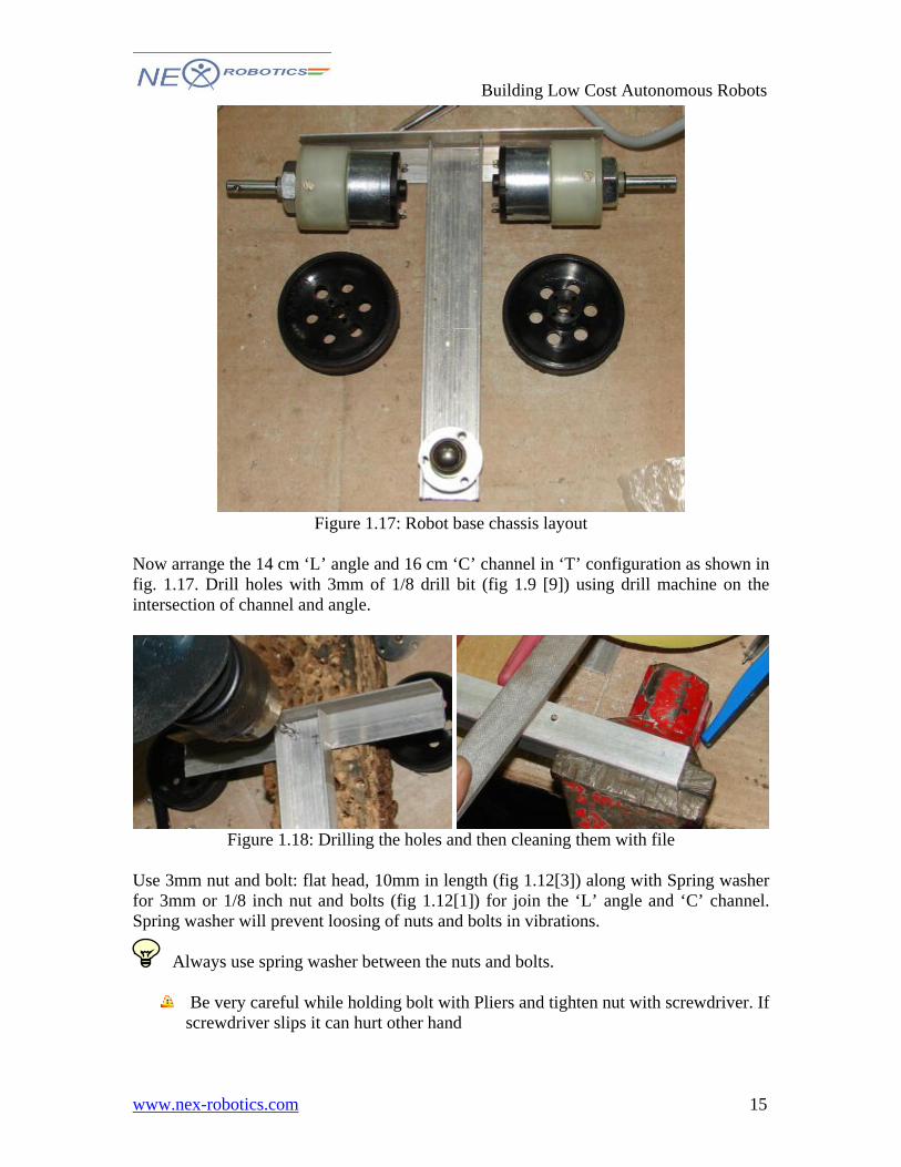
Figure 1.17: Robot base chassis layout
Now arrange the 14 cm ‘L’ angle and 16 cm ‘C’ channel in ‘T’ configuration as shown in fig. 1.17. Drill holes with 3mm of 1/8 drill bit (fig 1.9 [9]) using drill machine on the intersection of channel and angle.
Figure 1.18: Drilling the holes and then cleaning them with file
Use 3mm nut and bolt: flat head, 10mm in length (fig 1.12[3]) along with Spring washer for 3mm or 1/8 inch nut and bolts (fig 1.12[1]) for join the ‘L’ angle and ‘C’ channel. Spring washer will prevent loosing of nuts and bolts in vibrations. Always use spring washer between the nuts and bolts.
Be very careful while holding bolt with Pliers and tighten nut with screwdriver. If screwdriver slips it can hurt other hand
15
Building Low Cost Autonomous Robots
www.nex-robotics.com
Figure 1.18: Fitting ‘T’ joint with nuts and bolts
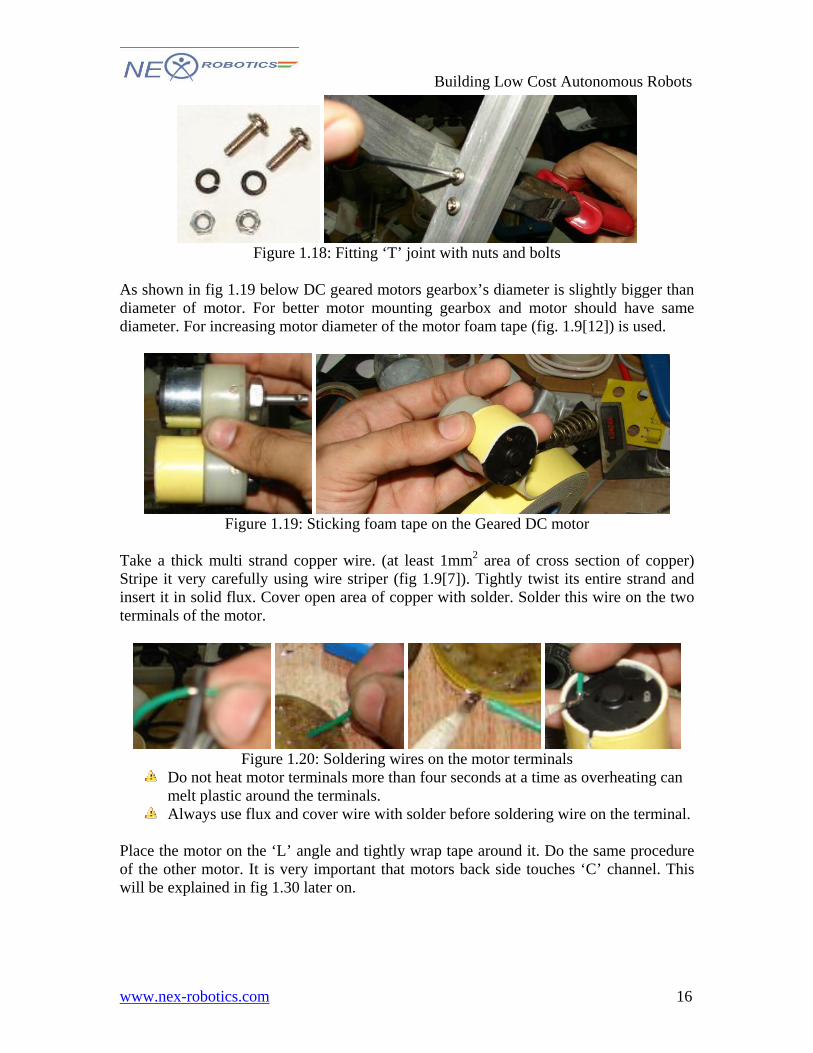
As shown in fig 1.19 below DC geared motors gearbox’s diameter is slightly bigger than diameter of motor. For better motor mounting gearbox and motor should have same diameter. For increasing motor diameter of the motor foam tape (fig. 1.9[12]) is used.
Figure 1.19: Sticking foam tape on the Geared DC motor
Take a thick multi strand copper wire. (at least 1mm2 area of cross section of copper) Stripe it very carefully using wire striper (fig 1.9[7]). Tightly twist its entire strand and insert it in solid flux. Cover open area of copper with solder. Solder this wire on the two terminals of the motor.
Figure 1.20: Soldering wires on the motor terminals
Do not heat motor terminals more than four seconds at a time as overheating can melt plastic around the terminals.
Always use flux and cover wire with solder before soldering wire on the terminal. Place the motor on the ‘L’ angle and tightly wrap tape around it. Do the same procedure of the other motor. It is very important that motors back side touches ‘C’ channel. This will be explained in fig 1.30 later on.
16
Building Low Cost Autonomous Robots
www.nex-robotics.com
Figure 1.21: Mounting motor on the chassis using tape
Advantage of this method is that you can replace motor in very short time in case motor gets damaged.
Figure 1.22: Photo showing chassis after motor mounting.
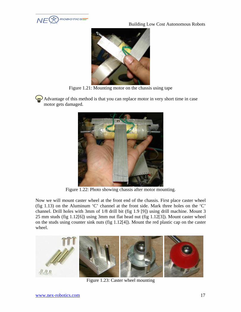
Now we will mount caster wheel at the front end of the chassis. First place caster wheel (fig 1.13) on the Aluminum ‘C’ channel at the front side. Mark three holes on the ‘C’ channel. Drill holes with 3mm of 1/8 drill bit (fig 1.9 [9]) using drill machine. Mount 3 25 mm studs (fig 1.12[6]) using 3mm nut flat head nut (fig 1.12[3]). Mount caster wheel on the studs using counter sink nuts (fig 1.12[4]). Mount the red plastic cap on the caster wheel.
Figure 1.23: Caster wheel mounting
17
Building Low Cost Autonomous Robots
www.nex-robotics.com
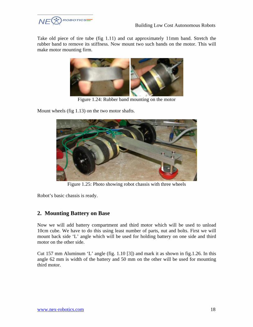
Take old piece of tire tube (fig 1.11) and cut approximately 11mm band. Stretch the rubber band to remove its stiffness. Now mount two such bands on the motor. This will make motor mounting firm.
Figure 1.24: Rubber band mounting on the motor
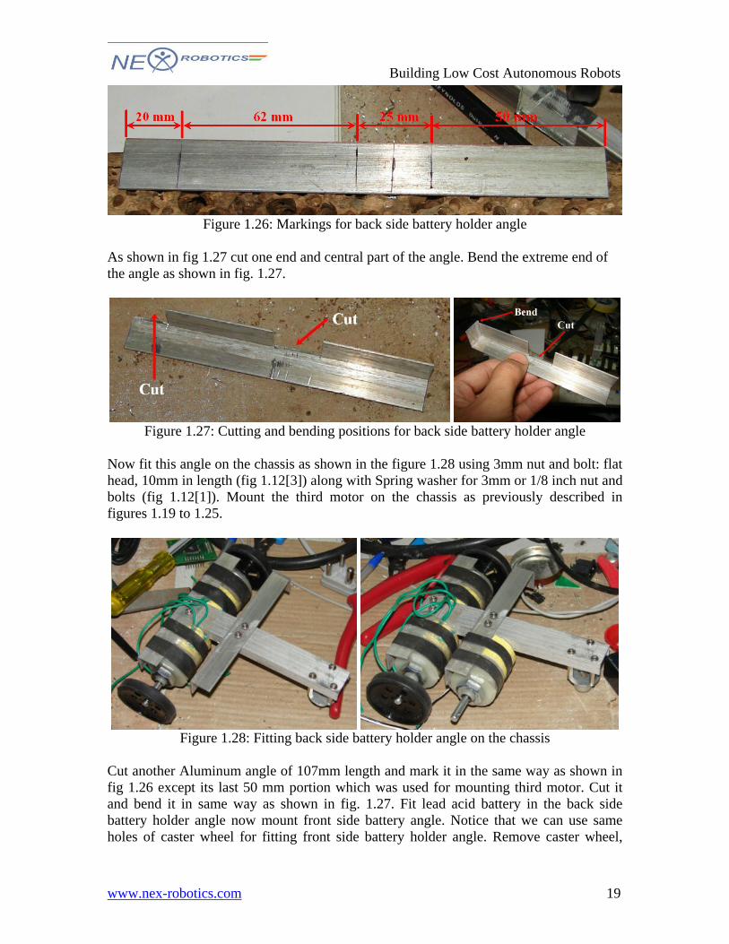
Mount wheels (fig 1.13) on the two motor shafts.
Figure 1.25: Photo showing robot chassis with three wheels
Robot’s basic chassis is ready. 2. Mounting Battery on Base Now we will add battery compartment and third motor which will be used to unload 10cm cube. We have to do this using least number of parts, nut and bolts. First we will mount back side ‘L’ angle which will be used for holding battery on one side and third motor on the other side. Cut 157 mm Aluminum ‘L’ angle (fig. 1.10 [3]) and mark it as shown in fig.1.26. In this angle 62 mm is width of the battery and 50 mm on the other will be used for mounting third motor.
18
Building Low Cost Autonomous Robots
www.nex-robotics.com
Figure 1.26: Markings for back side battery holder angle
As shown in fig 1.27 cut one end and central part of the angle. Bend the extreme end of the angle as shown in fig. 1.27.
Figure 1.27: Cutting and bending positions for back side battery holder angle
Now fit this angle on the chassis as shown in the figure 1.28 using 3mm nut and bolt: flat head, 10mm in length (fig 1.12[3]) along with Spring washer for 3mm or 1/8 inch nut and bolts (fig 1.12[1]). Mount the third motor on the chassis as previously described in figures 1.19 to 1.25.
Figure 1.28: Fitting back side battery holder angle on the chassis
Cut another Aluminum angle of 107mm length and mark it in the same way as shown in fig 1.26 except its last 50 mm portion which was used for mounting third motor. Cut it and bend it in same way as shown in fig. 1.27. Fit lead acid battery in the back side battery holder angle now mount front side battery angle. Notice that we can use same holes of caster wheel for fitting front side battery holder angle. Remove caster wheel,
19
Building Low Cost Autonomous Robots
www.nex-robotics.com
mark these holes on the front battery holder angle. Drill holes and fit this angle along with caster wheel. Fig 1.29 shows top and bottom view of the chassis with battery holder.
Figure 1.29: Fitting front side battery angle
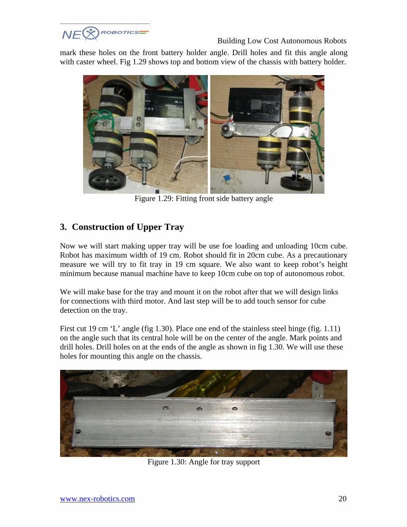
3. Construction of Upper Tray Now we will start making upper tray will be use foe loading and unloading 10cm cube. Robot has maximum width of 19 cm. Robot should fit in 20cm cube. As a precautionary measure we will try to fit tray in 19 cm square. We also want to keep robot’s height minimum because manual machine have to keep 10cm cube on top of autonomous robot. We will make base for the tray and mount it on the robot after that we will design links for connections with third motor. And last step will be to add touch sensor for cube detection on the tray. First cut 19 cm ‘L’ angle (fig 1.30). Place one end of the stainless steel hinge (fig. 1.11) on the angle such that its central hole will be on the center of the angle. Mark points and drill holes. Drill holes on at the ends of the angle as shown in fig 1.30. We will use these holes for mounting this angle on the chassis.
Figure 1.30: Angle for tray support
20
Building Low Cost Autonomous Robots
www.nex-robotics.com
Now Place this angle on top of angle which is holding two driving motors. Drill two holes on the chassis and drill holes. Fit 35 mm studs (fig 1.12[7]) between tray support angle and angle holding two motors (fig 1.31).
Figure 1.31: mounting tray support angle on the chassis
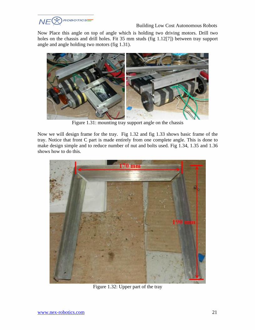
Now we will design frame for the tray. Fig 1.32 and fig 1.33 shows basic frame of the tray. Notice that front C part is made entirely from one complete angle. This is done to make design simple and to reduce number of nut and bolts used. Fig 1.34, 1.35 and 1.36 shows how to do this.
Figure 1.32: Upper part of the tray
21
Building Low Cost Autonomous Robots
www.nex-robotics.com
Figure 1.33: Base angle for the tray
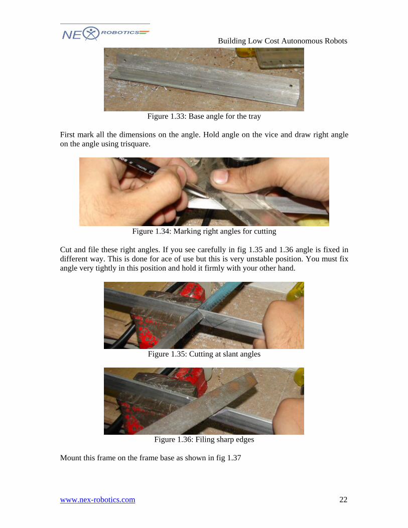
First mark all the dimensions on the angle. Hold angle on the vice and draw right angle on the angle using trisquare.
Figure 1.34: Marking right angles for cutting
Cut and file these right angles. If you see carefully in fig 1.35 and 1.36 angle is fixed in different way. This is done for ace of use but this is very unstable position. You must fix angle very tightly in this position and hold it firmly with your other hand.
Figure 1.35: Cutting at slant angles
Figure 1.36: Filing sharp edges
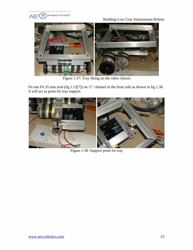
Mount this frame on the frame base as shown in fig 1.37
22
Building Low Cost Autonomous Robots
www.nex-robotics.com
Figure 1.37: Tray fitting on the robot chassis
Fit one Fit 35 mm stud (fig 1.12[7]) on ‘C’ channel in the front side as shown in fig 1.38. It will act as point for tray support.
Figure 1.38: Support point for tray
23
Building Low Cost Autonomous Robots
www.nex-robotics.com
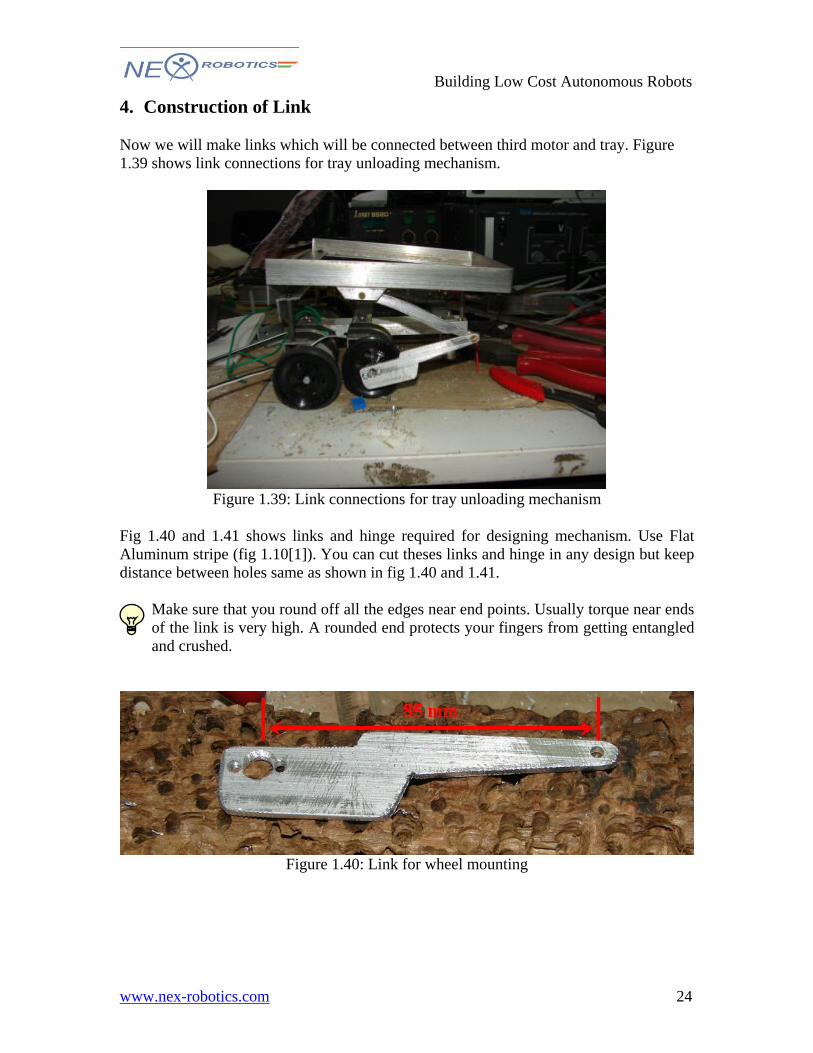
4. Construction of Link Now we will make links which will be connected between third motor and tray. Figure 1.39 shows link connections for tray unloading mechanism.
Figure 1.39: Link connections for tray unloading mechanism
Fig 1.40 and 1.41 shows links and hinge required for designing mechanism. Use Flat Aluminum stripe (fig 1.10[1]). You can cut theses links and hinge in any design but keep distance between holes same as shown in fig 1.40 and 1.41.
Make sure that you round off all the edges near end points. Usually torque near ends of the link is very high. A rounded end protects your fingers from getting entangled and crushed.
Figure 1.40: Link for wheel mounting
24
Building Low Cost Autonomous Robots
www.nex-robotics.com
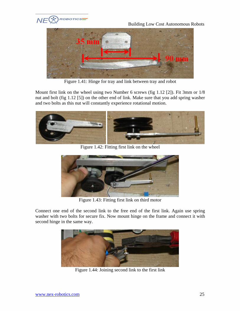
Figure 1.41: Hinge for tray and link between tray and robot
Mount first link on the wheel using two Number 6 screws (fig 1.12 [2]). Fit 3mm or 1/8 nut and bolt (fig 1.12 [5]) on the other end of link. Make sure that you add spring washer and two bolts as this nut will constantly experience rotational motion.
Figure 1.42: Fitting first link on the wheel
Figure 1.43: Fitting first link on third motor
Connect one end of the second link to the free end of the first link. Again use spring washer with two bolts for secure fix. Now mount hinge on the frame and connect it with second hinge in the same way.
Figure 1.44: Joining second link to the first link
25
Building Low Cost Autonomous Robots
www.nex-robotics.com
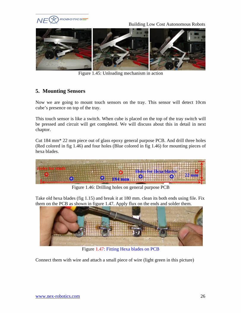
Figure 1.45: Unloading mechanism in action
5. Mounting Sensors Now we are going to mount touch sensors on the tray. This sensor will detect 10cm cube’s presence on top of the tray. This touch sensor is like a switch. When cube is placed on the top of the tray switch will be pressed and circuit will get completed. We will discuss about this in detail in next chaptor. Cut 184 mm* 22 mm piece out of glass epoxy general purpose PCB. And drill three holes (Red colored in fig 1.46) and four holes (Blue colored in fig 1.46) for mounting pieces of hexa blades.
Figure 1.46: Drilling holes on general purpose PCB
Take old hexa blades (fig 1.15) and break it at 180 mm. clean its both ends using file. Fix them on the PCB as shown in figure 1.47. Apply flux on the ends and solder them.
Figure 1.47: Fitting Hexa blades on PCB
Connect them with wire and attach a small piece of wire (light green in this picture)
26

Building Low Cost Autonomous Robots
www.nex-robotics.com
Figure 1.48: Joining hexa blades with common connection
Mount this PCB on the back side as shown in fig 1.49. Make sure that blades are not touching at the front end but there is at least 5mm clearance between blade and frame. When 10 cm cube will be placed on the tray, hexa blades will bend and it will make contact with frame. If body of robot is grounded and other pin is connected to microcontroller it will complete circuit and robot can sense that cube is placed on top of the robot.
Figure 1.49: Final touch sensor assembly
27
Building Low Cost Autonomous Robots
www.nex-robotics.com
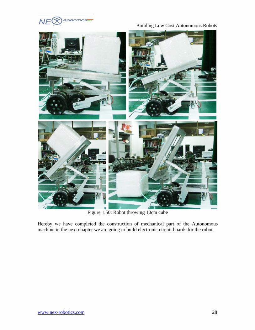
Figure 1.50: Robot throwing 10cm cube
Hereby we have completed the construction of mechanical part of the Autonomous machine in the next chapter we are going to build electronic circuit boards for the robot.
28