buck boost transformer catalog pages
DESCRIPTION
ÂTRANSCRIPT
6 Buck–Boost Transformers
Contact Technical Services at (800) 377-4384 with any questions. Visit our website at www.solahd.com.
230
Accessories
• Surge Protective Devices
• Active Tracking® Filters
Selection Steps1. Input Line Voltage
Measure the supply voltage with a voltmeter.
2. Voltage Required for the Load
Check the load equipment to determine the voltage requirement.
3. kVA or Ampere Rating of the Load
Find either the load kVA or the load amperage requirements. This information is listed on the nameplate of the load equipment.
4. Frequency
Either 50 or 60 Hz. The frequency of the transformer must match the frequency of the load.
5. Number of Phases
Single or three phase line and load must match. (A transformer cannot convert single to three phase.) A common application is to make a single phase connection from a three phase supply by using one phase of the three phase supply circuit. Be careful not to overload that phase of the three phase supply. For buck-boost applications the supply must provide load kVA – not just the nameplate rating of the buck-boost. Refer to the Selection Tables on the following pages.
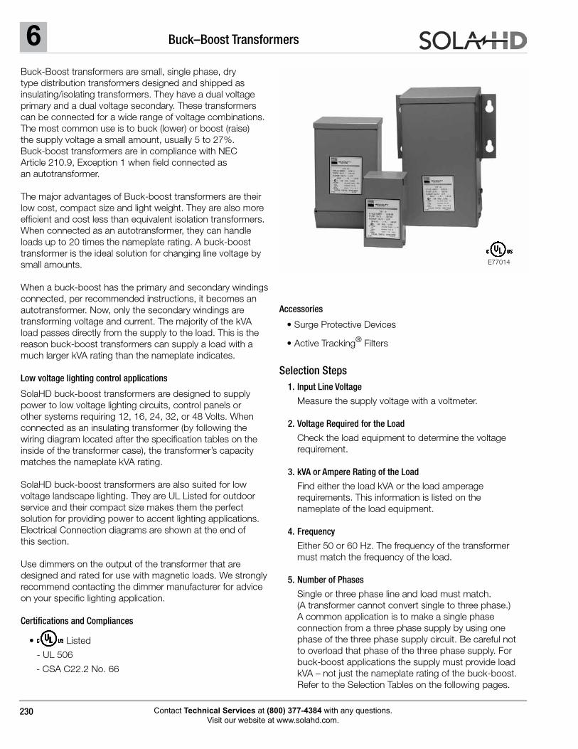
Buck-Boost transformers are small, single phase, dry type distribution transformers designed and shipped as insulating/isolating transformers. They have a dual voltage primary and a dual voltage secondary. These transformers can be connected for a wide range of voltage combinations. The most common use is to buck (lower) or boost (raise) the supply voltage a small amount, usually 5 to 27%. Buck-boost transformers are in compliance with NEC Article 210.9, Exception 1 when field connected as an autotransformer.
The major advantages of Buck-boost transformers are their low cost, compact size and light weight. They are also more efficient and cost less than equivalent isolation transformers. When connected as an autotransformer, they can handle loads up to 20 times the nameplate rating. A buck-boost transformer is the ideal solution for changing line voltage by small amounts.
When a buck-boost has the primary and secondary windings connected, per recommended instructions, it becomes an autotransformer. Now, only the secondary windings are transforming voltage and current. The majority of the kVA load passes directly from the supply to the load. This is the reason buck-boost transformers can supply a load with a much larger kVA rating than the nameplate indicates.
Low voltage lighting control applications
SolaHD buck-boost transformers are designed to supply power to low voltage lighting circuits, control panels or other systems requiring 12, 16, 24, 32, or 48 Volts. When connected as an insulating transformer (by following the wiring diagram located after the specification tables on the inside of the transformer case), the transformer’s capacity matches the nameplate kVA rating.
SolaHD buck-boost transformers are also suited for low voltage landscape lighting. They are UL Listed for outdoor service and their compact size makes them the perfect solution for providing power to accent lighting applications. Electrical Connection diagrams are shown at the end of this section.
Use dimmers on the output of the transformer that are designed and rated for use with magnetic loads. We strongly recommend contacting the dimmer manufacturer for advice on your specific lighting application.
Certifications and Compliances
• Listed
- UL 506
- CSA C22.2 No. 66
E77014
6Buck–Boost Transformers
Contact Technical Services at (800) 377-4384 with any questions. Visit our website at www.solahd.com.
231
Using the Selection Tables
1. Determine if you are trying to Boost (raise) or Buck (lower) your voltage. Select an input/output voltage combination that comes closest to matching your application from the appropriate single or three phase charts on the following pages.
2. Move across your selected input/output voltage row to the amperage or kVA rating closest to, but greater than the rating required by your load.
3. Reading the top of the column will give you the catalog number of the exact buck-boost transformer
you need. See the Specification Tables on the next page.
4. Connect the transformers according to the diagram indicated. See the Electrical Connections section at the
end of this section. Connection diagrams are packed with each transformer.
Three phase, buck-boost applications require two or three transformers. Check the “Quantity Required” column of the Three Phase Selection Tables for the exact quantity.
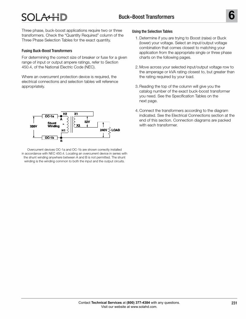
Fusing Buck-Boost Transformers
For determining the correct size of breaker or fuse for a given range of input or output ampere ratings, refer to Section 450.4, of the National Electric Code (NEC).
Where an overcurrent protection device is required, the electrical connections and selection tables will reference appropriately.
Overcurrent devices OC-1a and OC-1b are shown correctly installed in accordance with NEC 450.4. Locating an overcurrent device in series with
the shunt winding anywhere between A and B is not permitted. The shunt winding is the winding common to both the input and the output circuits.
6 Buck–Boost Transformers
Contact Technical Services at (800) 377-4384 with any questions. Visit our website at www.solahd.com.
232
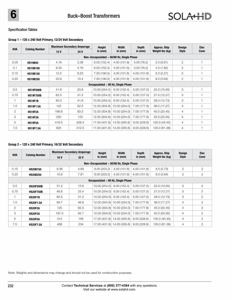
Group 2 – 120 x 240 Volt Primary, 16/32 Volt Secondary
Note: Weights and dimensions may change and should not be used for construction purposes.
Specification Tables
Group 1 – 120 x 240 Volt Primary, 12/24 Volt Secondary
KVA Catalog NumberMaximum Secondary Amperage Height
in (mm)Width
in (mm)Depth
in (mm)Approx. Ship
Weight lbs (kg)Design Style
Elec Conn12 V 24 V
Non-Encapsulated - 50/60 Hz, Single Phase
0.05 HS19B50 4.16 2.08 6.00 (152.4) 4.00 (101.6) 3.00 (76.2) 2.0 (0.91) 2 1
0.1 HS19B100 8.33 4.16 6.00 (152.4) 4.00 (101.6) 3.00 (76.2) 4.0 (1.82) 2 1
0.15 HS19B150 12.5 6.25 7.50 (190.5) 4.00 (101.6) 4.00 (101.6) 5.0 (2.27) 2 1
0.25 HS19B250 20.8 10.4 7.50 (190.5) 4.00 (101.6) 4.00 (101.6) 8.0 (3.64) 2 1
Encapsulated - 60 Hz, Single Phase
0.5 HS19F500B 41.6 20.8 10.00 (254.0) 6.00 (152.4) 5.00 (127.0) 22.0 (10.00) 3 1
0.75 HS19F750B 62.5 31.2 10.00 (254.0) 6.00 (152.4) 5.00 (127.0) 27.0 (12.27) 3 1
1 HS19F1B 83.3 41.6 10.00 (254.0) 6.00 (152.4) 5.00 (127.0) 28.0 (12.73) 3 1
1.5 HS19F1.5A 125 62.5 12.00 (304.8) 10.00 (254.0) 7.00 (177.8) 38.0 (17.27) 4 1
2 HS19F2A 166.6 83.3 12.00 (304.8) 10.00 (254.0) 7.00 (177.8) 45.0 (20.45) 4 1
3 HS19F3A 250 125 12.00 (304.8) 10.00 (254.0) 7.00 (177.8) 55.0 (25.00) 4 1
5 HS19F5A 416.5 208.3 17.00 (431.8) 14.00 (355.6) 9.00 (228.6) 100.0 (45.45) 4 1
7.5 HS19F7.5A 625 312.5 17.00 (431.8) 14.00 (355.6) 9.00 (228.6) 135.0 (61.36) 4 1
KVA Catalog NumberMaximum Secondary Amperage Height
in (mm)Width
in (mm)Depth
in (mm)Approx. Ship
Weight lbs (kg)Design Style
Elec Conn16 V 32 V
Non-Encapsulated - 50/60 Hz, Single Phase
0.15 HS20B150 9.38 4.69 8.00 (203.2) 4.00 (101.6) 4.00 (101.6) 6.0 (2.73) 2 2
0.25 HS20B250 15.6 7.81 8.00 (203.2) 4.00 (101.6) 4.00 (101.6) 8.0 (3.64) 2 2
Encapsulated - 60 Hz, Single Phase
0.5 HS20F500B 31.2 15.6 10.00 (254.0) 6.00 (152.4) 5.00 (127.0) 22.0 (10.00) 3 2
0.75 HS20F750B 46.8 23.4 10.00 (254.0) 6.00 (152.4) 5.00 (127.0) 27.0 (12.27) 3 2
1 HS20F1B 62.5 31.2 10.00 (254.0) 6.00 (152.4) 5.00 (127.0) 28.0 (12.73) 3 2
1.5 HS20F1.5A 93.7 46.8 12.00 (304.8) 10.00 (254.0) 7.00 (177.8) 38.0 (17.27) 4 2
2 HS20F2A 125 62.5 12.00 (304.8) 10.00 (254.0) 7.00 (177.8) 45.0 (20.45) 4 2
3 HS20F3A 187.5 93.7 12.00 (304.8) 10.00 (254.0) 7.00 (177.8) 55.0 (25.00) 4 2
5 HS20F5A 312 156 17.00 (431.8) 14.00 (355.6) 9.00 (228.6) 100.0 (45.45) 4 2
7.5 HS20F7.5A 468 234 17.00 (431.8) 14.00 (355.6) 9.00 (228.6) 135.0 (61.36) 4 2
6Buck–Boost Transformers
Contact Technical Services at (800) 377-4384 with any questions. Visit our website at www.solahd.com.
233
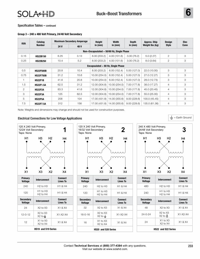
Group 3 – 240 x 480 Volt Primary, 24/48 Volt Secondary
Specification Tables – continued
KVACatalog Number
Maximum Secondary Amperage Height in (mm)
Width in (mm)
Depth in (mm)
Approx. Ship Weight lbs (kg)
Design Style
Elec Conn24 V 48 V
Non-Encapsulated - 50/60 Hz, Single Phase
0.15 HS22B150 6.25 3.13 8.00 (203.2) 4.00 (101.6) 3.00 (76.2) 5.0 (2.27) 2 3
0.25 HS22B250 10.4 5.2 8.00 (203.2) 4.00 (101.6) 3.00 (76.2) 8.0 (3.64) 2 3
Encapsulated - 60 Hz, Single Phase
0.5 HS22F500B 20.8 10.4 8.00 (203.2) 6.00 (152.4) 5.00 (127.0) 22.0 (10.00) 3 3
0.75 HS22F750B 31.2 15.6 10.00 (254.0) 6.00 (152.4) 5.00 (127.0) 27.0 (12.27) 3 3
1 HS22F1B 41.6 20.8 10.00 (254.0) 6.00 (152.4) 5.00 (127.0) 28.0 (12.73) 3 3
1.5 HS22F1.5A 62.5 31.2 12.00 (304.8) 10.00 (254.0) 7.00 (177.8) 38.0 (17.27) 4 3
2 HS22F2A 83.3 41.6 12.00 (304.8) 10.00 (254.0) 7.00 (177.8) 45.0 (20.45) 4 3
3 HS22F3A 125 62.5 12.00 (304.8) 10.00 (254.0) 7.00 (177.8) 55.0 (25.00) 4 3
5 HS22F5A 208 104 17.00 (431.8) 14.00 (355.6) 9.00 (228.6) 100.0 (45.45) 4 3
7.5 HS22F7.5A 312 156 17.00 (431.8) 14.00 (355.6) 9.00 (228.6) 135.0 (61.36) 4 3
Primary Voltage
InterconnectConnect Lines To
480 H2 to H3 H1 & H4
240H1 to H3 H2 to H4
H1 & H4
SecondaryVoltage
InterconnectConnect Lines To
48 X2 to X3 X1 & X4
24-0-24X2 to X3X2 to
X1-X2-X4
24X1 to X3 X2 to X4
X1 & X4
HS22 and S22 Series
Primary Voltage
InterconnectConnect Lines To
240 H2 to H3 H1 & H4
120H1 to H3 H2 to H4
H1 & H4
Secondary Voltage
InterconnectConnect Lines To
24 X2 to X3 X1 & X4
12-0-12X2 to X3 X2 to
X1-X2-X4
12X1 to X3X2 to X4
X1 & X4
HS19 and S19 Series
Primary Voltage
InterconnectConnect Lines To
240 H2 to H3 H1 & H4
120H1 to H3H2 to H4
H1 & H4
SecondaryVoltage
InterconnectConnect Lines To
32 X2 to X3 X1 & X4
16-0-16X2 to X3X2 to
X1-X2-X4
16X1 to X3X2 to X4
X1 & X4
HS20 and S20 Series
Electrical Connections for Low Voltage Applications
120 X 240 Volt Primary, 12/24 Volt Secondary Taps: None
120 X 240 Volt Primary, 16/32 Volt Secondary Taps: None
240 X 480 Volt Primary, 24/48 Volt Secondary Taps: None
1 2 3
= Earth Ground
H1 H2H3 H4
X1 X3 X2 X4
H1 H2H3 H4
X1 X3 X2 X4
H1 H2H3 H4
X1 X3 X2 X4
Note: Weights and dimensions may change and should not be used for construction purposes.
6 Buck–Boost Transformers
Contact Technical Services at (800) 377-4384 with any questions. Visit our website at www.solahd.com.
234
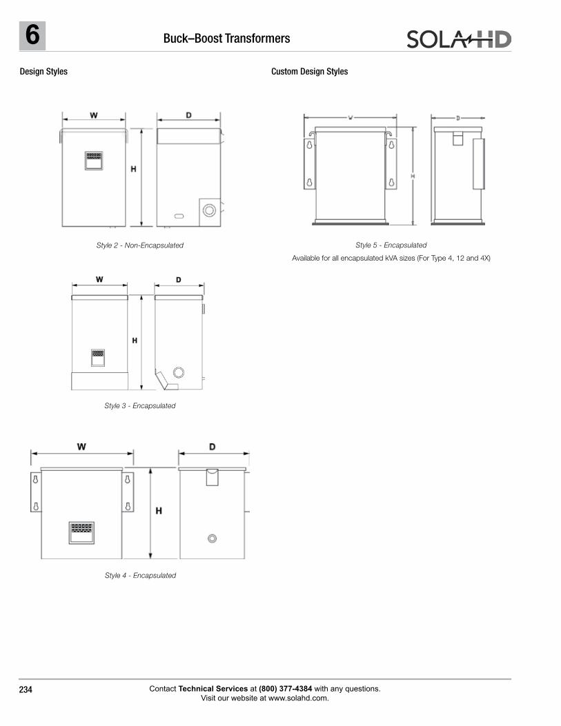
Design Styles
Style 4 - Encapsulated
Style 3 - Encapsulated
Style 2 - Non-Encapsulated Style 5 - Encapsulated
Available for all encapsulated kVA sizes (For Type 4, 12 and 4X)
Custom Design Styles
6Buck–Boost Transformers
Contact Technical Services at (800) 377-4384 with any questions. Visit our website at www.solahd.com.
235
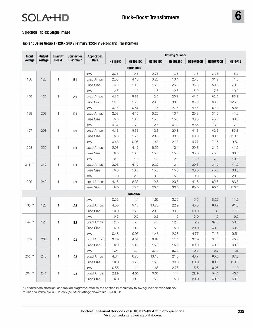
Selection Tables: Single Phase
Table 1: Using Group 1 (120 x 240 V Primary, 12/24 V Secondary) Transformers
* For alternate electrical connection diagrams, refer to the section immediately following the selection tables. ** Shaded items are 60 Hz only (All other ratings shown are 50/60 Hz).
Input Voltage
Output Voltage
Quantity Req’d
Connection Diagram *
Application Data
Catalog Number
HS19B50 HS19B100 HS19B150 HS19B250 HS19F500B HS19F750B HS19F1B
BOOSTING
100 120 1 B1
kVA 0.25 0.5 0.75 1.25 2.5 3.75 5.0
Load Amps 2.08 4.16 6.25 10.4 20.8 31.2 41.6
Fuse Size 6.0 10.0 15.0 25.0 35.0 50.0 70.0
109 120 1 A1
kVA 0.5 1.0 1.5 2.5 5.0 7.5 10.0
Load Amps 4.16 8.33 12.5 20.8 41.6 62.5 83.3
Fuse Size 10.0 15.0 20.0 30.0 60.0 90.0 125.0
189 208 1 D1
kVA 0.43 0.87 1.3 2.16 4.33 6.49 8.65
Load Amps 2.08 4.16 6.25 10.4 20.8 31.2 41.6
Fuse Size 6.0 10.0 15.0 15.0 30.0 45.0 60.0
197 208 1 C1
kVA 0.87 1.73 2.6 4.33 8.65 13.0 17.3
Load Amps 4.16 8.33 12.5 20.8 41.6 62.5 83.3
Fuse Size 6.0 15.0 20.0 30.0 60.0 90.0 110.0
208 229 1 D1
kVA 0.48 0.95 1.43 2.38 4.77 7.15 9.54
Load Amps 2.08 4.16 6.25 10.4 20.8 31.2 41.6
Fuse Size 6.0 10.0 15.0 15.0 30.0 45.0 60.0
218 ** 240 1 D1
kVA 0.5 1.0 1.5 2.5 5.0 7.5 10.0
Load Amps 2.08 4.16 6.25 10.4 20.8 31.2 41.6
Fuse Size 6.0 10.0 15.0 15.0 30.0 45.0 60.0
229 240 1 C1
kVA 1.0 2.0 3.0 5.0 10.0 15.0 20.0
Load Amps 4.16 8.33 12.5 20.8 41.6 62.5 83.3
Fuse Size 6.0 15.0 20.0 30.0 60.0 90.0 110.0
BUCKING
132 ** 120 1 A2
kVA 0.55 1.1 1.65 2.75 5.5 8.25 11.0
Load Amps 4.58 9.16 13.75 22.9 45.8 68.7 91.6
Fuse Size 10.0 15.0 20.0 30.0 60.0 80 110
144 ** 120 1 B2
kVA 0.3 0.6 0.9 1.5 3.0 4.5 6.0
Load Amps 2.5 5.0 7.5 12.5 25 37.5 50.0
Fuse Size 6.0 10.0 15.0 15.0 30.0 40.0 60.0
229 208 1 D2
kVA 0.48 0.95 1.43 2.38 4.77 7.15 9.54
Load Amps 2.29 4.58 6.88 11.4 22.9 34.4 45.8
Fuse Size 6.0 10.0 15.0 15.0 30.0 40.0 60.0
252 ** 240 1 C2
kVA 1.04 2.1 3.15 5.25 10.5 15.7 21
Load Amps 4.34 8.75 13.13 21.8 43.7 65.6 87.5
Fuse Size 10.0 15.0 15.0 30.0 60.0 80.0 110.0
264 ** 240 1 D2
kVA 0.55 1.1 1.65 2.75 5.5 8.25 11.0
Load Amps 2.29 4.58 6.88 11.4 22.9 34.3 45.8
Fuse Size 6.0 10.0 15.0 15.0 30.0 40.0 60.0
6 Buck–Boost Transformers
Contact Technical Services at (800) 377-4384 with any questions. Visit our website at www.solahd.com.
236
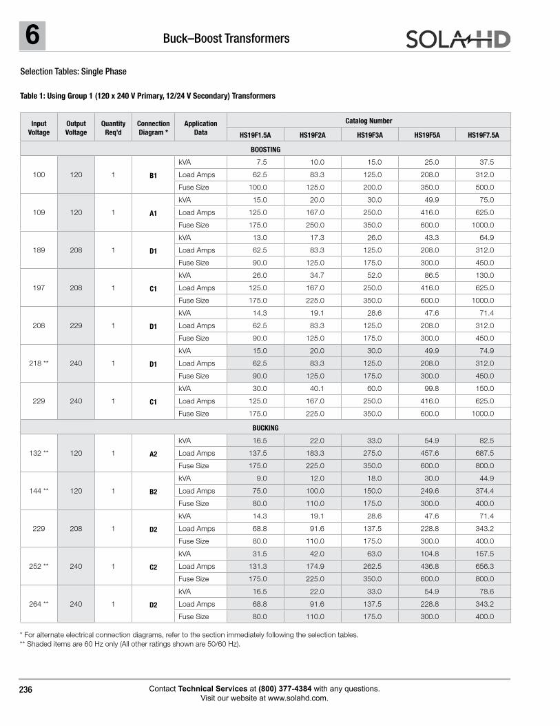
Selection Tables: Single Phase
Table 1: Using Group 1 (120 x 240 V Primary, 12/24 V Secondary) Transformers
* For alternate electrical connection diagrams, refer to the section immediately following the selection tables. ** Shaded items are 60 Hz only (All other ratings shown are 50/60 Hz).
Input Voltage
Output Voltage
Quantity Req’d
Connection Diagram *
Application Data
Catalog Number
HS19F1.5A HS19F2A HS19F3A HS19F5A HS19F7.5A
BOOSTING
100 120 1 B1
kVA 7.5 10.0 15.0 25.0 37.5
Load Amps 62.5 83.3 125.0 208.0 312.0
Fuse Size 100.0 125.0 200.0 350.0 500.0
109 120 1 A1
kVA 15.0 20.0 30.0 49.9 75.0
Load Amps 125.0 167.0 250.0 416.0 625.0
Fuse Size 175.0 250.0 350.0 600.0 1000.0
189 208 1 D1
kVA 13.0 17.3 26.0 43.3 64.9
Load Amps 62.5 83.3 125.0 208.0 312.0
Fuse Size 90.0 125.0 175.0 300.0 450.0
197 208 1 C1
kVA 26.0 34.7 52.0 86.5 130.0
Load Amps 125.0 167.0 250.0 416.0 625.0
Fuse Size 175.0 225.0 350.0 600.0 1000.0
208 229 1 D1
kVA 14.3 19.1 28.6 47.6 71.4
Load Amps 62.5 83.3 125.0 208.0 312.0
Fuse Size 90.0 125.0 175.0 300.0 450.0
218 ** 240 1 D1
kVA 15.0 20.0 30.0 49.9 74.9
Load Amps 62.5 83.3 125.0 208.0 312.0
Fuse Size 90.0 125.0 175.0 300.0 450.0
229 240 1 C1
kVA 30.0 40.1 60.0 99.8 150.0
Load Amps 125.0 167.0 250.0 416.0 625.0
Fuse Size 175.0 225.0 350.0 600.0 1000.0
BUCKING
132 ** 120 1 A2
kVA 16.5 22.0 33.0 54.9 82.5
Load Amps 137.5 183.3 275.0 457.6 687.5
Fuse Size 175.0 225.0 350.0 600.0 800.0
144 ** 120 1 B2
kVA 9.0 12.0 18.0 30.0 44.9
Load Amps 75.0 100.0 150.0 249.6 374.4
Fuse Size 80.0 110.0 175.0 300.0 400.0
229 208 1 D2
kVA 14.3 19.1 28.6 47.6 71.4
Load Amps 68.8 91.6 137.5 228.8 343.2
Fuse Size 80.0 110.0 175.0 300.0 400.0
252 ** 240 1 C2
kVA 31.5 42.0 63.0 104.8 157.5
Load Amps 131.3 174.9 262.5 436.8 656.3
Fuse Size 175.0 225.0 350.0 600.0 800.0
264 ** 240 1 D2
kVA 16.5 22.0 33.0 54.9 78.6
Load Amps 68.8 91.6 137.5 228.8 343.2
Fuse Size 80.0 110.0 175.0 300.0 400.0
6Buck–Boost Transformers
Contact Technical Services at (800) 377-4384 with any questions. Visit our website at www.solahd.com.
237
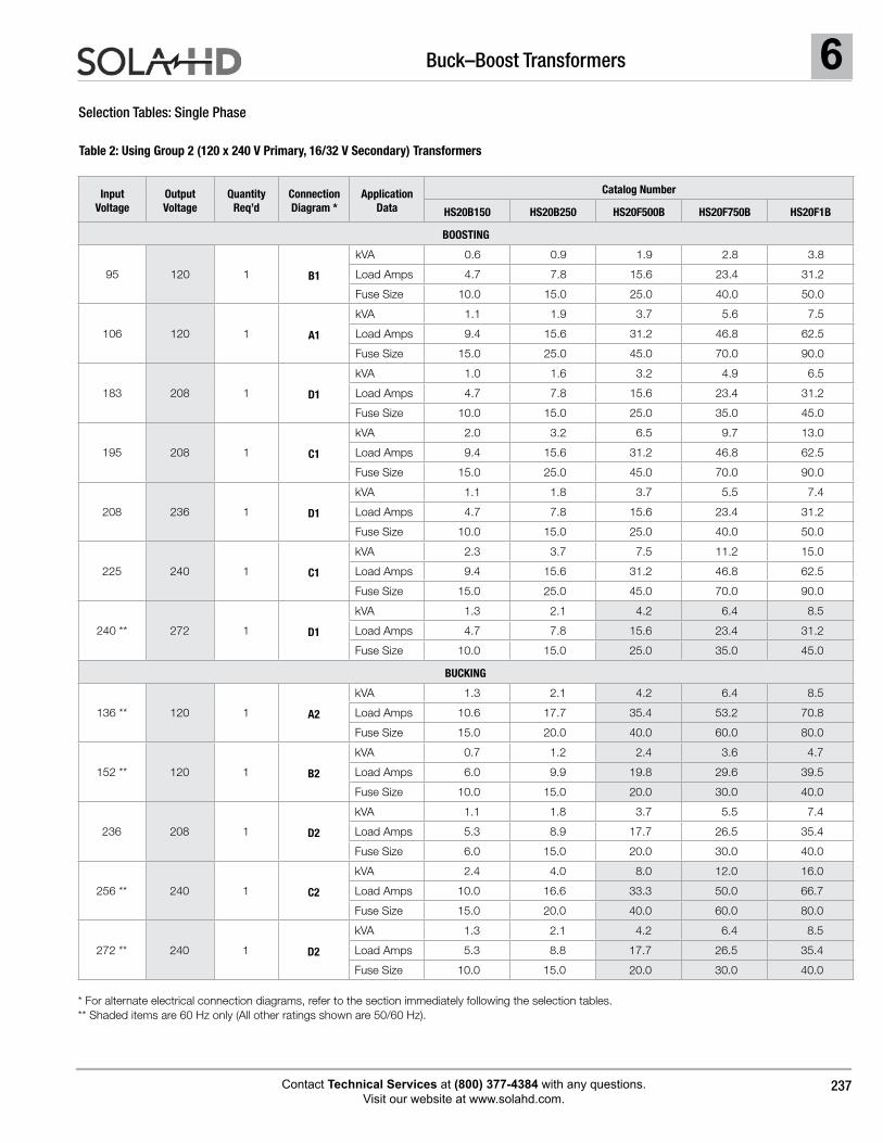
Selection Tables: Single Phase
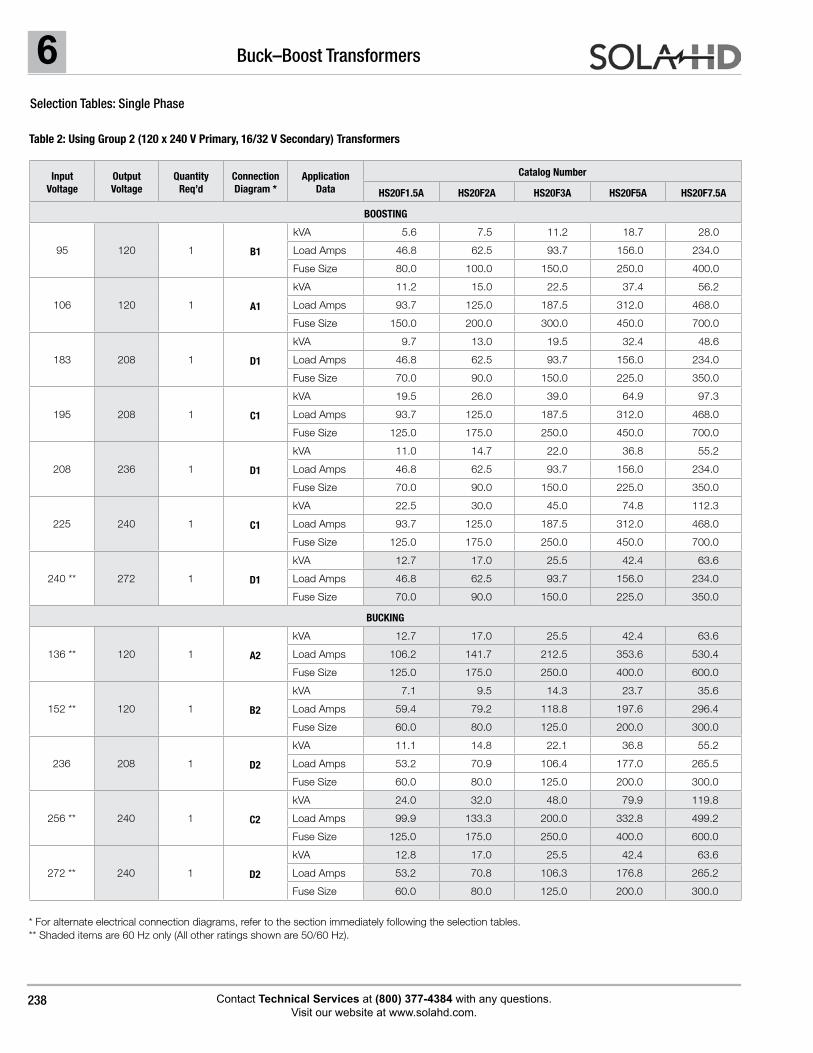
Table 2: Using Group 2 (120 x 240 V Primary, 16/32 V Secondary) Transformers
* For alternate electrical connection diagrams, refer to the section immediately following the selection tables. ** Shaded items are 60 Hz only (All other ratings shown are 50/60 Hz).
Input Voltage
Output Voltage
Quantity Req’d
Connection Diagram *
Application Data
Catalog Number
HS20B150 HS20B250 HS20F500B HS20F750B HS20F1B
BOOSTING
95 120 1 B1
kVA 0.6 0.9 1.9 2.8 3.8
Load Amps 4.7 7.8 15.6 23.4 31.2
Fuse Size 10.0 15.0 25.0 40.0 50.0
106 120 1 A1
kVA 1.1 1.9 3.7 5.6 7.5
Load Amps 9.4 15.6 31.2 46.8 62.5
Fuse Size 15.0 25.0 45.0 70.0 90.0
183 208 1 D1
kVA 1.0 1.6 3.2 4.9 6.5
Load Amps 4.7 7.8 15.6 23.4 31.2
Fuse Size 10.0 15.0 25.0 35.0 45.0
195 208 1 C1
kVA 2.0 3.2 6.5 9.7 13.0
Load Amps 9.4 15.6 31.2 46.8 62.5
Fuse Size 15.0 25.0 45.0 70.0 90.0
208 236 1 D1
kVA 1.1 1.8 3.7 5.5 7.4
Load Amps 4.7 7.8 15.6 23.4 31.2
Fuse Size 10.0 15.0 25.0 40.0 50.0
225 240 1 C1
kVA 2.3 3.7 7.5 11.2 15.0
Load Amps 9.4 15.6 31.2 46.8 62.5
Fuse Size 15.0 25.0 45.0 70.0 90.0
240 ** 272 1 D1
kVA 1.3 2.1 4.2 6.4 8.5
Load Amps 4.7 7.8 15.6 23.4 31.2
Fuse Size 10.0 15.0 25.0 35.0 45.0
BUCKING
136 ** 120 1 A2
kVA 1.3 2.1 4.2 6.4 8.5
Load Amps 10.6 17.7 35.4 53.2 70.8
Fuse Size 15.0 20.0 40.0 60.0 80.0
152 ** 120 1 B2
kVA 0.7 1.2 2.4 3.6 4.7
Load Amps 6.0 9.9 19.8 29.6 39.5
Fuse Size 10.0 15.0 20.0 30.0 40.0
236 208 1 D2
kVA 1.1 1.8 3.7 5.5 7.4
Load Amps 5.3 8.9 17.7 26.5 35.4
Fuse Size 6.0 15.0 20.0 30.0 40.0
256 ** 240 1 C2
kVA 2.4 4.0 8.0 12.0 16.0
Load Amps 10.0 16.6 33.3 50.0 66.7
Fuse Size 15.0 20.0 40.0 60.0 80.0
272 ** 240 1 D2
kVA 1.3 2.1 4.2 6.4 8.5
Load Amps 5.3 8.8 17.7 26.5 35.4
Fuse Size 10.0 15.0 20.0 30.0 40.0
6 Buck–Boost Transformers
Contact Technical Services at (800) 377-4384 with any questions. Visit our website at www.solahd.com.
238
Selection Tables: Single Phase
Table 2: Using Group 2 (120 x 240 V Primary, 16/32 V Secondary) Transformers
* For alternate electrical connection diagrams, refer to the section immediately following the selection tables. ** Shaded items are 60 Hz only (All other ratings shown are 50/60 Hz).
Input Voltage
Output Voltage
Quantity Req’d
Connection Diagram *
Application Data
Catalog Number
HS20F1.5A HS20F2A HS20F3A HS20F5A HS20F7.5A
BOOSTING
95 120 1 B1
kVA 5.6 7.5 11.2 18.7 28.0
Load Amps 46.8 62.5 93.7 156.0 234.0
Fuse Size 80.0 100.0 150.0 250.0 400.0
106 120 1 A1
kVA 11.2 15.0 22.5 37.4 56.2
Load Amps 93.7 125.0 187.5 312.0 468.0
Fuse Size 150.0 200.0 300.0 450.0 700.0
183 208 1 D1
kVA 9.7 13.0 19.5 32.4 48.6
Load Amps 46.8 62.5 93.7 156.0 234.0
Fuse Size 70.0 90.0 150.0 225.0 350.0
195 208 1 C1
kVA 19.5 26.0 39.0 64.9 97.3
Load Amps 93.7 125.0 187.5 312.0 468.0
Fuse Size 125.0 175.0 250.0 450.0 700.0
208 236 1 D1
kVA 11.0 14.7 22.0 36.8 55.2
Load Amps 46.8 62.5 93.7 156.0 234.0
Fuse Size 70.0 90.0 150.0 225.0 350.0
225 240 1 C1
kVA 22.5 30.0 45.0 74.8 112.3
Load Amps 93.7 125.0 187.5 312.0 468.0
Fuse Size 125.0 175.0 250.0 450.0 700.0
240 ** 272 1 D1
kVA 12.7 17.0 25.5 42.4 63.6
Load Amps 46.8 62.5 93.7 156.0 234.0
Fuse Size 70.0 90.0 150.0 225.0 350.0
BUCKING
136 ** 120 1 A2
kVA 12.7 17.0 25.5 42.4 63.6
Load Amps 106.2 141.7 212.5 353.6 530.4
Fuse Size 125.0 175.0 250.0 400.0 600.0
152 ** 120 1 B2
kVA 7.1 9.5 14.3 23.7 35.6
Load Amps 59.4 79.2 118.8 197.6 296.4
Fuse Size 60.0 80.0 125.0 200.0 300.0
236 208 1 D2
kVA 11.1 14.8 22.1 36.8 55.2
Load Amps 53.2 70.9 106.4 177.0 265.5
Fuse Size 60.0 80.0 125.0 200.0 300.0
256 ** 240 1 C2
kVA 24.0 32.0 48.0 79.9 119.8
Load Amps 99.9 133.3 200.0 332.8 499.2
Fuse Size 125.0 175.0 250.0 400.0 600.0
272 ** 240 1 D2
kVA 12.8 17.0 25.5 42.4 63.6
Load Amps 53.2 70.8 106.3 176.8 265.2
Fuse Size 60.0 80.0 125.0 200.0 300.0
6Buck–Boost Transformers
Contact Technical Services at (800) 377-4384 with any questions. Visit our website at www.solahd.com.
239
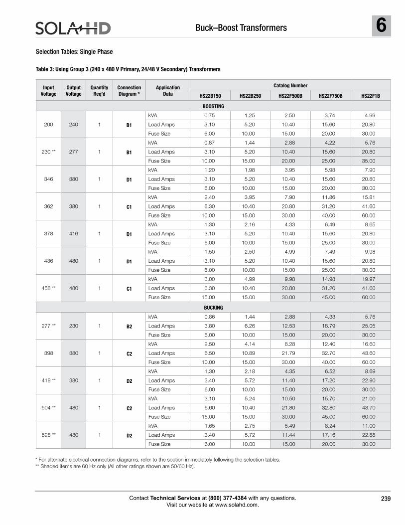
Selection Tables: Single Phase
Table 3: Using Group 3 (240 x 480 V Primary, 24/48 V Secondary) Transformers
* For alternate electrical connection diagrams, refer to the section immediately following the selection tables. ** Shaded items are 60 Hz only (All other ratings shown are 50/60 Hz).
Input Voltage
Output Voltage
Quantity Req’d
Connection Diagram *
Application Data
Catalog Number
HS22B150 HS22B250 HS22F500B HS22F750B HS22F1B
BOOSTING
200 240 1 B1
kVA 0.75 1.25 2.50 3.74 4.99
Load Amps 3.10 5.20 10.40 15.60 20.80
Fuse Size 6.00 10.00 15.00 20.00 30.00
230 ** 277 1 B1
kVA 0.87 1.44 2.88 4.22 5.76
Load Amps 3.10 5.20 10.40 15.60 20.80
Fuse Size 10.00 15.00 20.00 25.00 35.00
346 380 1 D1
kVA 1.20 1.98 3.95 5.93 7.90
Load Amps 3.10 5.20 10.40 15.60 20.80
Fuse Size 6.00 10.00 15.00 20.00 30.00
362 380 1 C1
kVA 2.40 3.95 7.90 11.86 15.81
Load Amps 6.30 10.40 20.80 31.20 41.60
Fuse Size 10.00 15.00 30.00 40.00 60.00
378 416 1 D1
kVA 1.30 2.16 4.33 6.49 8.65
Load Amps 3.10 5.20 10.40 15.60 20.80
Fuse Size 6.00 10.00 15.00 25.00 30.00
436 480 1 D1
kVA 1.50 2.50 4.99 7.49 9.98
Load Amps 3.10 5.20 10.40 15.60 20.80
Fuse Size 6.00 10.00 15.00 25.00 30.00
458 ** 480 1 C1
kVA 3.00 4.99 9.98 14.98 19.97
Load Amps 6.30 10.40 20.80 31.20 41.60
Fuse Size 15.00 15.00 30.00 45.00 60.00
BUCKING
277 ** 230 1 B2
kVA 0.86 1.44 2.88 4.33 5.76
Load Amps 3.80 6.26 12.53 18.79 25.05
Fuse Size 6.00 10.00 15.00 20.00 30.00
398 380 1 C2
kVA 2.50 4.14 8.28 12.40 16.60
Load Amps 6.50 10.89 21.79 32.70 43.60
Fuse Size 10.00 15.00 30.00 40.00 60.00
418 ** 380 1 D2
kVA 1.30 2.18 4.35 6.52 8.69
Load Amps 3.40 5.72 11.40 17.20 22.90
Fuse Size 6.00 10.00 15.00 20.00 30.00
504 ** 480 1 C2
kVA 3.10 5.24 10.50 15.70 21.00
Load Amps 6.60 10.40 21.80 32.80 43.70
Fuse Size 15.00 15.00 30.00 45.00 60.00
528 ** 480 1 D2
kVA 1.65 2.75 5.49 8.24 11.00
Load Amps 3.40 5.72 11.44 17.16 22.88
Fuse Size 6.00 10.00 15.00 20.00 30.00
6 Buck–Boost Transformers
Contact Technical Services at (800) 377-4384 with any questions. Visit our website at www.solahd.com.
240
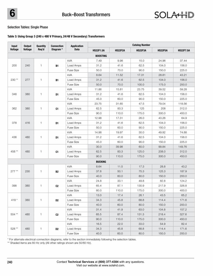
Selection Tables: Single Phase
Table 3: Using Group 3 (240 x 480 V Primary, 24/48 V Secondary) Transformers
* For alternate electrical connection diagrams, refer to the section immediately following the selection tables. ** Shaded items are 60 Hz only (All other ratings shown are 50/60 Hz).
Input Voltage
Output Voltage
Quantity Req’d
Connection Diagram *
Application Data
Catalog Number
HS22F1.5A HS22F2A HS22F3A HS22F5A HS22F7.5A
BOOSTING
200 240 1 B1
kVA 7.49 9.98 15.0 24.96 37.44
Load Amps 31.2 41.6 62.5 104.0 156.0
Fuse Size 50.0 70.0 90.0 150.0 225.0
230 ** 277 1 B1
kVA 8.64 11.52 17.31 28.81 43.21
Load Amps 31.2 41.6 62.5 104.0 156.0
Fuse Size 50.0 70.0 100.0 175.0 250.0
346 380 1 D1
kVA 11.86 15.81 23.75 39.52 59.28
Load Amps 31.2 41.6 62.5 104.0 156.0
Fuse Size 45.0 60.0 90.0 150.0 225.0
362 380 1 C1
kVA 23.75 31.65 47.5 79.04 118.56
Load Amps 62.5 83.3 125 208 312.0
Fuse Size 90.0 110.0 175.0 300.0 450.0
378 416 1 D1
kVA 12.98 17.31 26.0 43.26 64.9
Load Amps 31.2 41.6 62.5 104.0 156.0
Fuse Size 50.0 60.0 90.0 150.0 225.0
436 480 1 D1
kVA 14.98 19.97 30.0 49.92 74.88
Load Amps 31.2 41.6 62.5 104.0 156.0
Fuse Size 45.0 60.0 90.0 150.0 225.0
458 ** 480 1 C1
kVA 30.0 39.98 60.0 99.84 149.76
Load Amps 62.5 83.3 125.0 208.0 312.0
Fuse Size 90.0 110.0 175.0 300.0 450.0
BUCKING
277 ** 230 1 B2
kVA 8.64 11.5 17.3 28.8 43.2
Load Amps 37.6 50.1 75.3 125.3 187.9
Fuse Size 40.0 60.0 80.0 150.0 200.0
398 380 1 C2
kVA 24.8 33.1 49.8 82.8 124.2
Load Amps 65.4 87.1 130.9 217.9 326.8
Fuse Size 80.0 110.0 175.0 300.0 400.0
418 * 380 1 D2
kVA 13.0 17.4 26.1 43.5 65.2
Load Amps 34.3 45.8 68.8 114.4 171.6
Fuse Size 40.0 60.0 80.0 150.0 200.0
504 ** 480 1 C2
kVA 31.4 41.9 63.0 104.8 157.2
Load Amps 65.5 87.4 131.3 218.4 327.6
Fuse Size 90.0 110.0 175.0 300.0 450.0
528 ** 480 1 D2
kVA 16.5 22.0 33.0 54.9 82.4
Load Amps 34.3 45.8 68.8 114.4 171.6
Fuse Size 40.0 60.0 80.0 150.0 200.0
6Buck–Boost Transformers
Contact Technical Services at (800) 377-4384 with any questions. Visit our website at www.solahd.com.
241
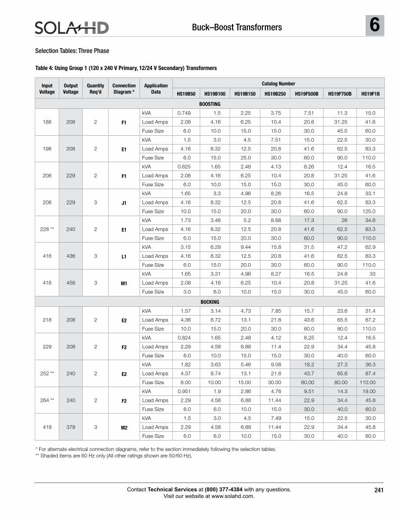
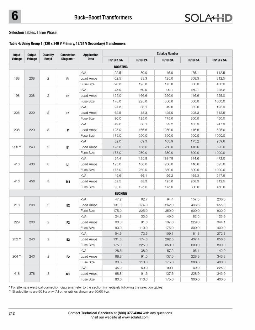
Selection Tables: Three Phase
Table 4: Using Group 1 (120 x 240 V Primary, 12/24 V Secondary) Transformers
* For alternate electrical connection diagrams, refer to the section immediately following the selection tables. ** Shaded items are 60 Hz only (All other ratings shown are 50/60 Hz).
Input Voltage
Output Voltage
Quantity Req’d
Connection Diagram *
Application Data
Catalog Number
HS19B50 HS19B100 HS19B150 HS19B250 HS19F500B HS19F750B HS19F1B
BOOSTING
188 208 2 F1
kVA 0.749 1.5 2.25 3.75 7.51 11.3 15.0
Load Amps 2.08 4.16 6.25 10.4 20.8 31.25 41.6
Fuse Size 6.0 10.0 15.0 15.0 30.0 45.0 60.0
198 208 2 E1
kVA 1.5 3.0 4.5 7.51 15.0 22.5 30.0
Load Amps 4.16 8.32 12.5 20.8 41.6 62.5 83.3
Fuse Size 6.0 15.0 25.0 30.0 60.0 90.0 110.0
208 229 2 F1
kVA 0.825 1.65 2.48 4.13 8.26 12.4 16.5
Load Amps 2.08 4.16 6.25 10.4 20.8 31.25 41.6
Fuse Size 6.0 10.0 15.0 15.0 30.0 45.0 60.0
208 229 3 J1
kVA 1.65 3.3 4.96 8.26 16.5 24.8 33.1
Load Amps 4.16 8.32 12.5 20.8 41.6 62.5 83.3
Fuse Size 10.0 15.0 20.0 30.0 60.0 90.0 125.0
228 ** 240 2 E1
kVA 1.73 3.46 5.2 8.68 17.3 26 34.6
Load Amps 4.16 8.32 12.5 20.8 41.6 62.5 83.3
Fuse Size 6.0 15.0 20.0 30.0 60.0 90.0 110.0
416 436 3 L1
kVA 3.15 6.29 9.44 15.8 31.5 47.2 62.9
Load Amps 4.16 8.32 12.5 20.8 41.6 62.5 83.3
Fuse Size 6.0 15.0 20.0 30.0 60.0 90.0 110.0
416 458 3 M1
kVA 1.65 3.31 4.96 8.27 16.5 24.8 33
Load Amps 2.08 4.16 6.25 10.4 20.8 31.25 41.6
Fuse Size 3.0 6.0 10.0 15.0 30.0 45.0 60.0
BUCKING
218 208 2 E2
kVA 1.57 3.14 4.73 7.85 15.7 23.6 31.4
Load Amps 4.36 8.72 13.1 21.8 43.6 65.5 87.2
Fuse Size 10.0 15.0 20.0 30.0 60.0 80.0 110.0
229 208 2 F2
kVA 0.824 1.65 2.48 4.12 8.25 12.4 16.5
Load Amps 2.29 4.58 6.88 11.4 22.9 34.4 45.8
Fuse Size 6.0 10.0 15.0 15.0 30.0 40.0 60.0
252 ** 240 2 E2
kVA 1.82 3.63 5.46 9.08 18.2 27.3 36.3
Load Amps 4.37 8.74 13.1 21.8 43.7 65.6 87.4
Fuse Size 6.00 10.00 15.00 30.00 60.00 80.00 110.00
264 ** 240 2 F2
kVA 0.951 1.9 2.86 4.76 9.51 14.3 19.00
Load Amps 2.29 4.58 6.88 11.44 22.9 34.4 45.8
Fuse Size 6.0 6.0 10.0 15.0 30.0 40.0 60.0
418 378 3 M2
kVA 1.5 3.0 4.5 7.49 15.0 22.5 30.0
Load Amps 2.29 4.58 6.88 11.44 22.9 34.4 45.8
Fuse Size 6.0 6.0 10.0 15.0 30.0 40.0 60.0
6 Buck–Boost Transformers
Contact Technical Services at (800) 377-4384 with any questions. Visit our website at www.solahd.com.
242
Selection Tables: Three Phase
Table 4: Using Group 1 (120 x 240 V Primary, 12/24 V Secondary) Transformers
* For alternate electrical connection diagrams, refer to the section immediately following the selection tables. ** Shaded items are 60 Hz only (All other ratings shown are 50/60 Hz).
Input Voltage
Output Voltage
Quantity Req'd
Connection Diagram *
Application Data
Catalog Number
HS19F1.5A HS19F2A HS19F3A HS19F5A HS19F7.5A
BOOSTING
188 208 2 F1
kVA 22.5 30.0 45.0 75.1 112.5
Load Amps 62.5 83.3 125.0 208.3 312.5
Fuse Size 90.0 125.0 175.0 300.0 450.0
198 208 2 E1
kVA 45.0 60.0 90.1 150.1 225.2
Load Amps 125.0 166.6 250.0 416.6 625.0
Fuse Size 175.0 225.0 350.0 600.0 1000.0
208 229 2 F1
kVA 24.8 33.1 49.6 82.6 123.9
Load Amps 62.5 83.3 125.0 208.3 312.5
Fuse Size 90.0 125.0 175.0 300.0 450.0
208 229 3 J1
kVA 49.6 66.1 99.2 165.3 247.9
Load Amps 125.0 166.6 250.0 416.6 625.0
Fuse Size 175.0 250.0 350.0 600.0 1000.0
228 ** 240 2 E1
kVA 52.0 69.3 103.9 173.2 259.8
Load Amps 125.0 166.6 250.0 416.6 625.0
Fuse Size 175.0 250.0 350.0 600.0 1000.0
416 436 3 L1
kVA 94.4 125.8 188.79 314.6 472.0
Load Amps 125.0 166.6 250.0 416.6 625.0
Fuse Size 175.0 250.0 350.0 600.0 1000.0
416 458 3 M1
kVA 49.6 66.1 99.2 165.3 247.9
Load Amps 62.5 83.3 125.0 208.3 312.5
Fuse Size 90.0 125.0 175.0 300.0 450.0
BUCKING
218 208 2 E2
kVA 47.2 62.7 94.4 157.3 236.0
Load Amps 131.0 174.0 262.0 436.6 655.0
Fuse Size 175.0 225.0 350.0 600.0 800.0
229 208 2 F2
kVA 24.8 33.0 49.6 82.5 123.9
Load Amps 68.8 91.6 137.6 229.0 344.1
Fuse Size 80.0 110.0 175.0 300.0 400.0
252 ** 240 2 E2
kVA 54.6 72.5 109.1 181.8 272.8
Load Amps 131.3 174.3 262.5 437.4 656.3
Fuse Size 175.0 225.0 350.0 600.0 800.0
264 ** 240 2 F2
kVA 28.6 38.0 57.2 95.1 142.9
Load Amps 68.8 91.5 137.5 228.8 343.8
Fuse Size 80.0 110.0 175.0 300.0 400.0
418 378 3 M2
kVA 45.0 59.9 90.1 149.9 225.2
Load Amps 68.8 91.6 137.6 228.9 343.9
Fuse Size 80.0 110.0 175.0 300.0 400.0
6Buck–Boost Transformers
Contact Technical Services at (800) 377-4384 with any questions. Visit our website at www.solahd.com.
243
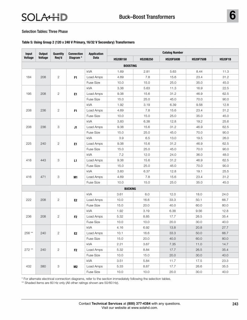
Selection Tables: Three Phase
Table 5: Using Group 2 (120 x 240 V Primary, 16/32 V Secondary) Transformers
* For alternate electrical connection diagrams, refer to the section immediately following the selection tables. ** Shaded items are 60 Hz only (All other ratings shown are 50/60 Hz).
Input Voltage
Output Voltage
Quantity Req'd
Connection Diagram *
Application Data
Catalog Number
HS20B150 HS20B250 HS20F500B HS20F750B HS20F1B
BOOSTING
184 208 2 F1
kVA 1.69 2.81 5.63 8.44 11.3
Load Amps 4.69 7.8 15.6 23.4 31.2
Fuse Size 10.0 15.0 25.0 35.0 45.0
195 208 2 E1
kVA 3.38 5.63 11.3 16.9 22.5
Load Amps 9.38 15.6 31.2 46.9 62.5
Fuse Size 15.0 25.0 45.0 70.0 90.0
208 236 2 F1
kVA 1.92 3.19 6.39 9.58 12.8
Load Amps 4.69 7.8 15.6 23.4 31.2
Fuse Size 10.0 15.0 25.0 35.0 45.0
208 236 3 J1
kVA 3.83 6.38 12.8 19.2 25.6
Load Amps 9.38 15.6 31.2 46.9 62.5
Fuse Size 15.0 25.0 45.0 70.0 90.0
225 240 2 E1
kVA 3.9 6.5 13.0 19.5 26.0
Load Amps 9.38 15.6 31.2 46.9 62.5
Fuse Size 15.0 25.0 45.0 70.0 90.0
416 443 3 L1
kVA 7.2 12.0 24.0 36.0 48.0
Load Amps 9.38 15.6 31.2 46.9 62.5
Fuse Size 15.0 25.0 45.0 70.0 90.0
416 471 3 M1
kVA 3.83 6.37 12.8 19.1 25.5
Load Amps 4.69 7.8 15.6 23.4 31.2
Fuse Size 10.0 15.0 25.0 35.0 45.0
BUCKING
222 208 2 E2
kVA 3.61 6.0 12.0 18.0 24.0
Load Amps 10.0 16.6 33.3 50.1 66.7
Fuse Size 15.0 20.0 40.0 60.0 80.0
236 208 2 F2
kVA 1.92 3.19 6.38 9.56 12.8
Load Amps 5.32 8.85 17.7 26.5 35.4
Fuse Size 10.0 10.0 20.0 30.0 40.0
256 ** 240 2 E2
kVA 4.16 6.92 13.8 20.8 27.7
Load Amps 10.1 16.6 33.3 50.0 66.7
Fuse Size 15.0 20.0 40.0 60.0 80.0
272 ** 240 2 F2
kVA 2.21 3.67 7.35 11.0 14.7
Load Amps 5.32 8.84 17.7 26.5 35.4
Fuse Size 10.0 15.0 20.0 30.0 40.0
432 380 3 M2
kVA 3.51 5.84 11.7 17.5 23.3
Load Amps 5.33 8.87 17.7 26.6 35.5
Fuse Size 10.0 10.0 20.0 30.0 40.0
6 Buck–Boost Transformers
Contact Technical Services at (800) 377-4384 with any questions. Visit our website at www.solahd.com.
244
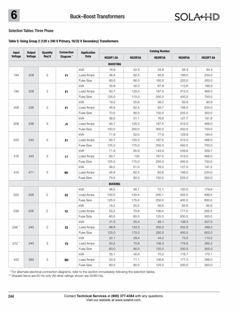
Selection Tables: Three Phase
Table 5: Using Group 2 (120 x 240 V Primary, 16/32 V Secondary) Transformers
Input Voltage
Output Voltage
Quantity Req'd
Connection Diagram *
Application Data
Catalog Number
HS20F1.5A HS20F2A HS20F3A HS20F5A HS20F7.5A
BOOSTING
184 208 2 F1
kVA 16.9 22.5 33.8 56.3 84.4
Load Amps 46.9 62.5 93.8 156.0 234.0
Fuse Size 60.0 90.0 150.0 225.0 350.0
195 208 2 E1
kVA 33.8 45.0 67.6 112.6 168.9
Load Amps 93.7 125.0 187.5 312.0 468.0
Fuse Size 125.0 175.0 250.0 450.0 700.0
208 236 2 F1
kVA 19.2 25.6 38.2 63.9 95.8
Load Amps 46.9 62.5 93.7 156.0 234.0
Fuse Size 70.0 90.0 150.0 225.0 350.0
208 236 3 J1
kVA 38.2 51.1 76.6 127.7 191.6
Load Amps 93.7 125.0 187.5 312.0 468.0
Fuse Size 150.0 200.0 300.0 450.0 700.0
225 240 2 E1
kVA 71.9 52.0 77.9 129.9 194.0
Load Amps 93.7 125.0 187.5 312.0 468.0
Fuse Size 125.0 175.0 250.0 450.0 700.0
416 443 3 L1
kVA 71.9 95.9 143.9 239.8 359.7
Load Amps 93.7 125 187.5 312.0 468.0
Fuse Size 125.0 175.0 250.0 450.0 700.0
416 471 3 M1
kVA 38.2 51.0 76.5 127.5 191.2
Load Amps 46.9 62.5 93.8 156.0 234.0
Fuse Size 70.0 90.0 150.0 225.0 350.0
BUCKING
222 208 2 E2
kVA 36.0 48.1 72.1 120.0 179.9
Load Amps 100.0 133.4 200.1 333.0 499.5
Fuse Size 125.0 175.0 250.0 400.0 600.0
236 208 2 F2
kVA 19.2 25.5 38.8 63.8 95.6
Load Amps 53.2 70.9 106.4 177.0 265.5
Fuse Size 60.0 80.0 125.0 200.0 300.0
256 ** 240 2 E2
kVA 41.5 55.4 83.1 138.3 207.5
Load Amps 99.9 133.3 200.0 332.8 499.2
Fuse Size 125.0 175.0 250.0 400.0 600.0
272 ** 240 2 F2
kVA 22.1 29.4 44.2 73.5 110.2
Load Amps 53.2 70.8 106.3 176.8 265.2
Fuse Size 60.0 80.0 125.0 200.0 300.0
432 380 3 M2
kVA 35.1 46.8 70.2 116.7 175.1
Load Amps 53.3 71.1 106.6 177.3 266.0
Fuse Size 60.0 80.0 125.0 200.0 300.0
* For alternate electrical connection diagrams, refer to the section immediately following the selection tables. ** Shaded items are 60 Hz only (All other ratings shown are 50/60 Hz).
6Buck–Boost Transformers
Contact Technical Services at (800) 377-4384 with any questions. Visit our website at www.solahd.com.
245
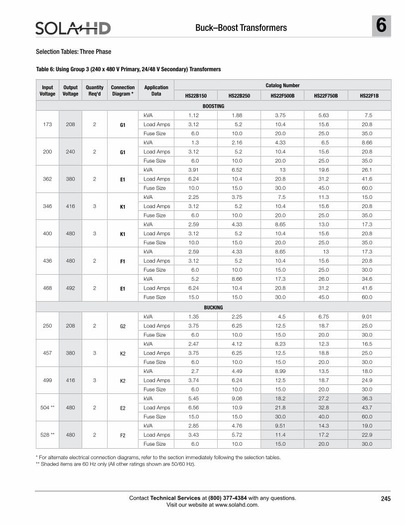
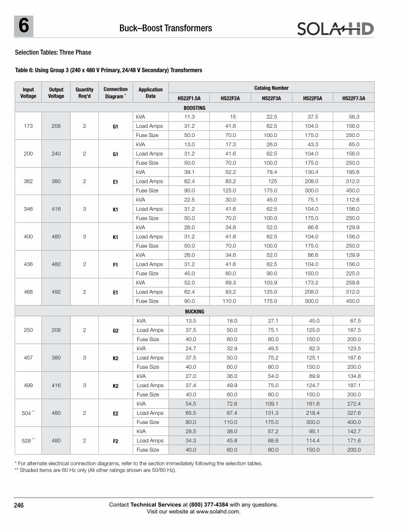
Selection Tables: Three Phase
Table 6: Using Group 3 (240 x 480 V Primary, 24/48 V Secondary) Transformers
Input Voltage
Output Voltage
Quantity Req'd
Connection Diagram *
Application Data
Catalog Number
HS22B150 HS22B250 HS22F500B HS22F750B HS22F1B
BOOSTING
173 208 2 G1
kVA 1.12 1.88 3.75 5.63 7.5
Load Amps 3.12 5.2 10.4 15.6 20.8
Fuse Size 6.0 10.0 20.0 25.0 35.0
200 240 2 G1
kVA 1.3 2.16 4.33 6.5 8.66
Load Amps 3.12 5.2 10.4 15.6 20.8
Fuse Size 6.0 10.0 20.0 25.0 35.0
362 380 2 E1
kVA 3.91 6.52 13 19.6 26.1
Load Amps 6.24 10.4 20.8 31.2 41.6
Fuse Size 10.0 15.0 30.0 45.0 60.0
346 416 3 K1
kVA 2.25 3.75 7.5 11.3 15.0
Load Amps 3.12 5.2 10.4 15.6 20.8
Fuse Size 6.0 10.0 20.0 25.0 35.0
400 480 3 K1
kVA 2.59 4.33 8.65 13.0 17.3
Load Amps 3.12 5.2 10.4 15.6 20.8
Fuse Size 10.0 15.0 20.0 25.0 35.0
436 480 2 F1
kVA 2.59 4.33 8.65 13 17.3
Load Amps 3.12 5.2 10.4 15.6 20.8
Fuse Size 6.0 10.0 15.0 25.0 30.0
468 492 2 E1
kVA 5.2 8.66 17.3 26.0 34.6
Load Amps 6.24 10.4 20.8 31.2 41.6
Fuse Size 15.0 15.0 30.0 45.0 60.0
BUCKING
250 208 2 G2
kVA 1.35 2.25 4.5 6.75 9.01
Load Amps 3.75 6.25 12.5 18.7 25.0
Fuse Size 6.0 10.0 15.0 20.0 30.0
457 380 3 K2
kVA 2.47 4.12 8.23 12.3 16.5
Load Amps 3.75 6.25 12.5 18.8 25.0
Fuse Size 6.0 10.0 15.0 20.0 30.0
499 416 3 K2
kVA 2.7 4.49 8.99 13.5 18.0
Load Amps 3.74 6.24 12.5 18.7 24.9
Fuse Size 6.0 10.0 15.0 20.0 30.0
504 ** 480 2 E2
kVA 5.45 9.08 18.2 27.2 36.3
Load Amps 6.56 10.9 21.8 32.8 43.7
Fuse Size 15.0 15.0 30.0 40.0 60.0
528 ** 480 2 F2
kVA 2.85 4.76 9.51 14.3 19.0
Load Amps 3.43 5.72 11.4 17.2 22.9
Fuse Size 6.0 10.0 15.0 20.0 30.0
* For alternate electrical connection diagrams, refer to the section immediately following the selection tables.** Shaded items are 60 Hz only (All other ratings shown are 50/60 Hz).
6 Buck–Boost Transformers
Contact Technical Services at (800) 377-4384 with any questions. Visit our website at www.solahd.com.
246
Selection Tables: Three Phase
Table 6: Using Group 3 (240 x 480 V Primary, 24/48 V Secondary) Transformers
Input Voltage
Output Voltage
Quantity Req'd
Connection Diagram *
Application Data
Catalog Number
HS22F1.5A HS22F2A HS22F3A HS22F5A HS22F7.5A
BOOSTING
173 208 2 G1
kVA 11.3 15 22.5 37.5 56.3
Load Amps 31.2 41.6 62.5 104.0 156.0
Fuse Size 50.0 70.0 100.0 175.0 250.0
200 240 2 G1
kVA 13.0 17.3 26.0 43.3 65.0
Load Amps 31.2 41.6 62.5 104.0 156.0
Fuse Size 50.0 70.0 100.0 175.0 250.0
362 380 2 E1
kVA 39.1 52.2 78.4 130.4 195.6
Load Amps 62.4 83.2 125 208.0 312.0
Fuse Size 90.0 125.0 175.0 300.0 450.0
346 416 3 K1
kVA 22.5 30.0 45.0 75.1 112.6
Load Amps 31.2 41.6 62.5 104.0 156.0
Fuse Size 50.0 70.0 100.0 175.0 250.0
400 480 3 K1
kVA 26.0 34.6 52.0 86.6 129.9
Load Amps 31.2 41.6 62.5 104.0 156.0
Fuse Size 50.0 70.0 100.0 175.0 250.0
436 480 2 F1
kVA 26.0 34.6 52.0 86.6 129.9
Load Amps 31.2 41.6 62.5 104.0 156.0
Fuse Size 45.0 60.0 90.0 150.0 225.0
468 492 2 E1
kVA 52.0 69.3 103.9 173.2 259.8
Load Amps 62.4 83.2 125.0 208.0 312.0
Fuse Size 90.0 110.0 175.0 300.0 450.0
BUCKING
250 208 2 G2
kVA 13.5 18.0 27.1 45.0 67.5
Load Amps 37.5 50.0 75.1 125.0 187.5
Fuse Size 40.0 60.0 80.0 150.0 200.0
457 380 3 K2
kVA 24.7 32.9 49.5 82.3 123.5
Load Amps 37.5 50.0 75.2 125.1 187.6
Fuse Size 40.0 60.0 80.0 150.0 200.0
499 416 3 K2
kVA 27.0 36.0 54.0 89.9 134.8
Load Amps 37.4 49.9 75.0 124.7 187.1
Fuse Size 40.0 60.0 80.0 150.0 200.0
504 ** 480 2 E2
kVA 54.5 72.6 109.1 181.6 272.4
Load Amps 65.5 87.4 131.3 218.4 327.6
Fuse Size 80.0 110.0 175.0 300.0 400.0
528 ** 480 2 F2
kVA 28.5 38.0 57.2 95.1 142.7
Load Amps 34.3 45.8 68.8 114.4 171.6
Fuse Size 40.0 60.0 80.0 150.0 200.0
* For alternate electrical connection diagrams, refer to the section immediately following the selection tables.** Shaded items are 60 Hz only (All other ratings shown are 50/60 Hz).
6Buck–Boost Transformers
Contact Technical Services at (800) 377-4384 with any questions. Visit our website at www.solahd.com.
247
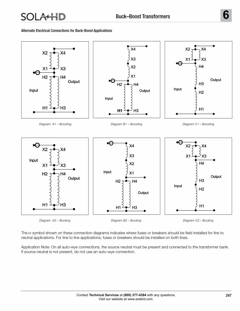
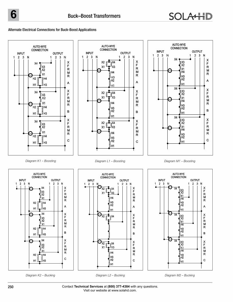
The O symbol shown on these connection diagrams indicates where fuses or breakers should be field installed for line to neutral applications. For line to line applications, fuses or breakers should be installed on both lines.
Application Note: On all auto-wye connections, the source neutral must be present and connected to the transformer bank. If source neutral is not present, do not use an auto-wye connection.
Alternate Electrical Connections for Buck-Boost Applications
Diagram A1 – Boosting Diagram B1 – Boosting Diagram C1 – Boosting
Diagram A2 – Bucking Diagram B2 – Bucking Diagram C2 – Bucking
Output
Input
H1
X1
H2
X2
H4
X4
H3
X3
Output
H2 H4
Input
H1 H3
X1
X2
X4
X3
Output
H2
H4
Input
H1
H3
X1
X2 X4
X3
Output
Input
H1
X1
H2
X2
H4
X4
H3
X3
Output
H2 H4
Input
H1 H3
X1
X2
X4
X3
Output
H2
H4
Input
H1
H3
X1
X2 X4
X3
6 Buck–Boost Transformers
Contact Technical Services at (800) 377-4384 with any questions. Visit our website at www.solahd.com.
248
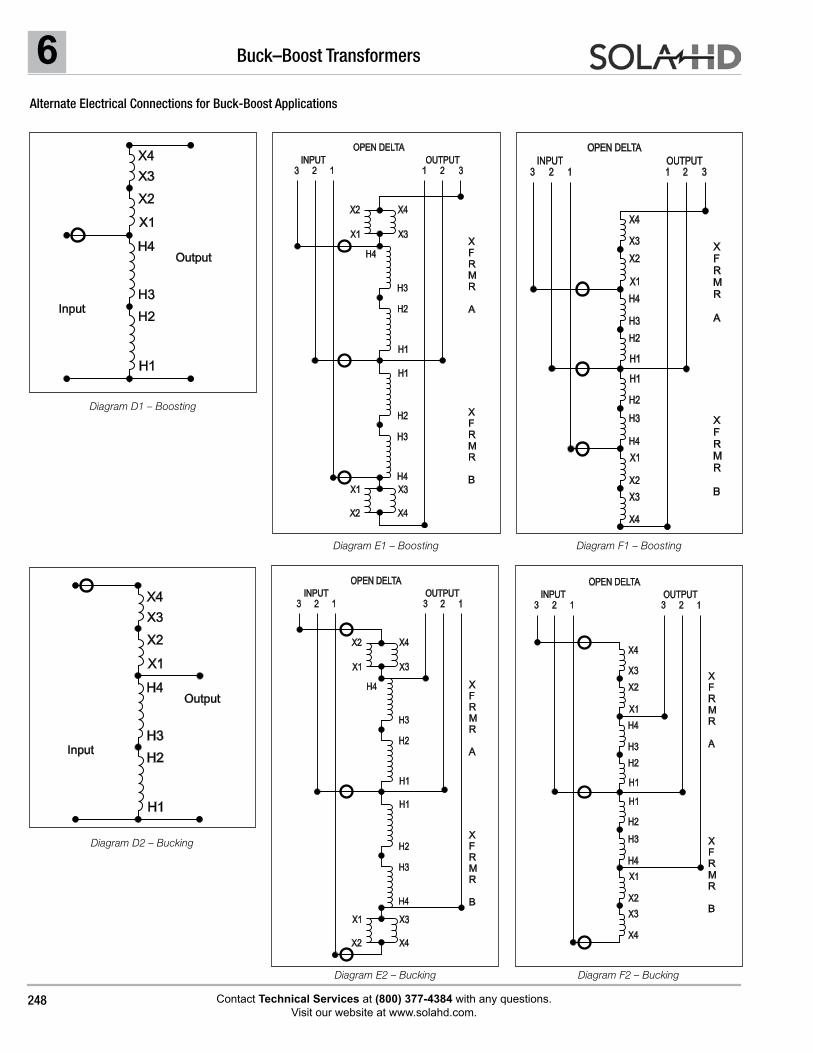
Alternate Electrical Connections for Buck-Boost Applications
Diagram F2 – Bucking
Diagram D1 – Boosting
Diagram E1 – Boosting Diagram F1 – Boosting
Diagram D2 – Bucking
Diagram E2 – Bucking
Output
H2
H4
Input
H1
H3
X1
X2
X4
X3
X
F
R
M
R
A
X
F
R
M
R
B
X1
X1
X2
X2
X4
X4
X3
X3
H1
H1
H2
H2
H4
H4
H3
H3
OUTPUT
OPEN DELTA
INPUT
1 2 3123
X
F
R
M
R
A
X
F
R
M
R
B
OUTPUT
OPEN DELTA
INPUT
123 1 2 3
X1
X1
X2
X2
X4
X4
X3
X3
H1
H1
H2
H2
H4
H4
H3
H3
Output
H2
H4
Input
H1
H3
X1
X2
X4
X3
X
F
R
M
R
A
X
F
R
M
R
B
OPEN DELTA
OUTPUT
1231
INPUT
23
X1
X1
X2
X2
X4
X4
X3
X3
H1
H1
H2
H2
H4
H4
H3
H3
X
F
R
M
R
A
X
F
R
M
R
B
OUTPUT
OPEN DELTA
INPUT
123 123
X1
X1
X2
X2
X4
X4
X3
X3
H1
H1
H2
H2
H4
H4
H3
H3
6Buck–Boost Transformers
Contact Technical Services at (800) 377-4384 with any questions. Visit our website at www.solahd.com.
249
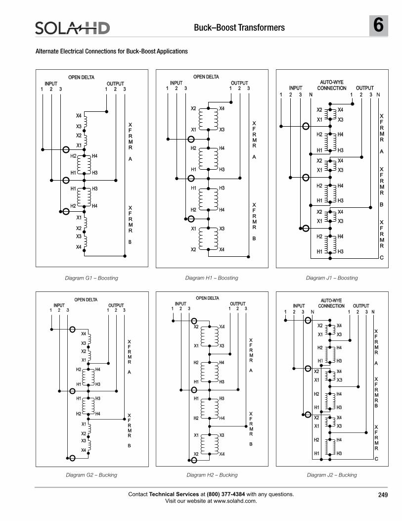
Alternate Electrical Connections for Buck-Boost Applications
Diagram J2 – Bucking
Diagram G1 – Boosting Diagram H1 – Boosting Diagram J1 – Boosting
Diagram G2 – Bucking Diagram H2 – Bucking
X
F
R
M
R
A
X
F
R
M
R
B
OUTPUT
OPEN DELTA
INPUT
1 2 31 2 3
H4
H4
H3
H3
X1
X1
X2
X2
X4
X4
X3
X3
H1
H1
H2
H2
X
F
R
M
R
A
X
F
R
M
R
B
OUTPUT
OPEN DELTA
INPUT
1 2 31 2 3
H4
H4
H3
H3
X1
X1
X2
X2
X4
X4
X3
X3
H1
H1
H2
H2
X
F
R
M
R
A
X
F
R
M
R
B
OUTPUT
OPEN DELTA
INPUT
1 2 31 2 3
H4
H4
H3
H3
X1
X1
X2
X2
X4
X4
X3
X3
H1
H1
H2
H2
X
F
R
M
R
A
X
F
R
M
R
B
X
F
R
M
R
C
OUTPUT
AUTO-WYE
CONNECTIONINPUT
1 2 3 N 1 2 3 N
H4
H4
H4
H3
H3
H3
X1
X1
X1
X2
X2
X2
X4
X4
X4
X3
X3
X3
H1
H1
H1
H2
H2
H2
X
F
R
M
R
A
X
F
R
M
R
B
OUTPUT
OPEN DELTA
INPUT
1 2 31 2 3
H4
H4
H3
H3
X1
X1
X2
X2
X4
X4
X3
X3
H1
H1
H2
H2
H4
H4
H3
H3
X1
X2 X4
X3
H1
H1
H2
H2
OUTPUT
AUTO-WYE
CONNECTIONINPUT
1 2 3 N 1 2 3 N
H4
H3
X1
X1
X2
X2
X4
X4
X3
X3
H1
H2
X
F
R
M
R
A
X
F
R
M
R
B
X
F
R
M
R
C
6 Buck–Boost Transformers
Contact Technical Services at (800) 377-4384 with any questions. Visit our website at www.solahd.com.
250
Alternate Electrical Connections for Buck-Boost Applications
Diagram M2 – Bucking
Diagram K1 – Boosting Diagram L1 – Boosting Diagram M1 – Boosting
Diagram K2 – Bucking Diagram L2 – Bucking
H4
H4
H3
H3
X1
X2
X3
H1
H1
H2
H2
AUTO-WYE
CONNECTION
INPUT
1 2 3 N
OUTPUT
1 2 3 N
H4
H3
X1
X1
X2
X2
X4
X4
X4
X3
X3
H1
H2
X
F
R
M
R
A
X
F
R
M
R
B
X
F
R
M
R
C
H4
H4
H3
H3
X1
X2X3
H1
H1
H2
H2
AUTO-WYE
CONNECTION
INPUT
1 2 3 N
OUTPUT
1 2 3 N
H4
H3
X1
X1
X2
X2
X4
X4
X4
X3
X3
H1
H2
X
F
R
M
R
A
X
F
R
M
R
B
X
F
R
M
R
C
H4
H4
H3
H3
X1
X2
X3
H1
H1
H2
H2
AUTO-WYE
CONNECTION
INPUT
1 2 3 N
OUTPUT
1 2 3 N
H4
H3
X1
X1
X2
X2
X4
X4
X4
X3
X3
H1
H2
X
F
R
M
R
A
X
F
R
M
R
B
X
F
R
M
R
C
H4
H4
H3
H3
X1
X2
X3
H1
H1
H2
H2
AUTO-WYE
CONNECTION
INPUT
1 2 3 N
OUTPUT
1 2 3 N
H4
H3
X1
X1
X2
X2
X4
X4
X4
X3
X3
H1
H2
X
F
R
M
R
A
X
F
R
M
R
B
X
F
R
M
R
C
H4
H3
X1
X2
X3
H1
H2
AUTO-WYE
CONNECTION
INPUT
1 2 3 N
OUTPUT
1 2 3 N
H4
H3
X1
X2
X2
X4
X4
X4
X3
H1
H2
X
F
R
M
R
A
X
F
R
M
R
B
X
F
R
M
R
C
H4
H4
H3
H3
X1
X2X3
H1
H1
H2
H2
AUTO-WYE
CONNECTION
INPUT
1 2 3 N
OUTPUT
1 2 3 N
H4
H3
X1
X1
X2
X2
X4
X4
X4
X3
X3
H1
H2
X
F
R
M
R
A
X
F
R
M
R
B
X
F
R
M
R
C
6Buck–Boost Transformers
Contact Technical Services at (800) 377-4384 with any questions. Visit our website at www.solahd.com.
251
Application Note
Application Limitations with Buck-Boost Transformers
1. A Buck-Boost transformer cannot be used to develop a three phase, four wire wye circuit from a three phase, three wire delta circuit.
A delta to wye connection does not supply enough current carrying capability to provide for unbalanced currents flowing in the neutral wire of the four wire circuit. The neutral created is not stable and under load will not deliver desired line to neutral voltages. This connection would also be in violation of the National Electric Code, Article 210.9.
2. Buck-Boost transformers cannot be used in a closed delta connection.
A closed delta requires more kVA capacity than a wye or an open delta connection, plus phase shifting comes into play on the output side.
3. Buck-Boost transformers should not be used to correct for voltage drop on a long circuit run where the load fluctuates.
Voltage drop varies with the load and buck-boost trans-formers are connected for a specific voltage change. If a buck-boost transformer was used to correct voltage drop during peak loading conditions, high voltages may result under light load conditions. This could be equally detrimental to the load and possibly pose safety hazards.
4. Buck-Boost transformers cannot be used to create a 240/120 Volt, single phase service from a 208Y/120 Volt three phase supply.
Two problems that would occur:
A. Two neutrals would exist on the same circuit. Since neutrals must be grounded according to the National Electric Code, a short circuit would be created.
B. Unbalanced line to output neutral voltages would be created; one line would read 120 Volts, the other 130+ Volts.
What is a Buck-Boost transformer and why is it used?
Isolation transformers have separate primary and secondary windings, electrically insulated and isolated from one another. With a relatively high voltage primary (typically 120, 240 or 480 Volts) and a relatively low voltage secondary (typically 12, 16, 24, 32 or 48 Volts), buck-boost transformers are designed to be field connected as autotransformers. These are transformers with one continuous winding, a portion of which is jointly shared between the input and the output. No electrical isolation is present in an autotransformer.
Buck-Boost transformers have two major uses:
1. When field connected as an autotransformer, they can be used to Buck (lower) or Boost (raise) available line voltage in the range of 5 to 27% and at a kVA rating many times that listed on the transformer nameplate.
2. When left as an isolation transformer, they can be used to supply power to low voltage circuits at the nameplate rating listed.
The importance of altering available line voltage.
Electrical equipment is designed to operate at maximum efficiency at a specific standard supply voltage. Your voltage may not be at the standard supply voltage level. Causes can be proximity to a large utility transformer, losses in the line voltage due to loads on that circuit, or a difference between the standard supply voltage available and the standard supply voltage needed to run the equipment.
Normally the problem is having low voltage available. Low voltage on a circuit, even as little as 5% lower can cause a decrease in incandescent light output, and a decrease in resistive heat output. With motors low voltage can cause a decrease in motor torque, an increase in motor amperage requirements, an increase in motor temperature and decrease in motor life expectancy.