btf s&-(&. t’&-*,./a/pdf.lowes.com/installationguides/027418149206_install.pdf · btf...
TRANSCRIPT

BTF Series Thermostat
WARNINGTurn the electrical power off at the electrical panel board (circuit breaker or fuse box) and lock or tag thepanel board door to prevent someone from turning on power while you are working on the heater. Failureto do so could result in serious electrical shock, burns, or possible death.
CONTROLSTurn knob counter-clockwise for cooler roomtemperature. Turn knob clockwise for warmerroom temperature.
When using electrical appliances, basic precautions should always be followed to reduce the risk of fire, electric shock, and injuryto persons, including the following:
Read all instructions before using this heater and thermostat. See our How-To Video at http://cadetco.com/installationvideo.phpAll electrical work and materials must comply with the National Electric Code (NEC), the Occupational Safety and Health Act (OSHA),and all state and local codes.
If you are uncomfortable working with electrical appliances, unable to follow theseguidelines, or do not have the necessary equipment; consult a licensed electrician.
InstallatIon InstructIons
www.cadetco.com Tel: 360-693-2505 p.o. Box 1675 vancouver, Wa 98668-1675
ImporTanT InSTrucTIonS
The BTF series heater mountthermostat for Cadet electricbaseboards can be used to controla baseboard heater at the unit.Designed to replace the detachablebaseboard end plate, the BTF easilyinstalls onto either end of a Cadet F-series baseboard heater. The BTF line voltage thermostat is capable of switching up to 22 amps, of a resistive load, at 120, 208 or 240 VAC. Setpointtemperature range: 45º - 80ºF.
Cooler Warm
er
BTF1 BTF2
Save TheSe InSTrucTIonS
TOOLS REQUIRED• Phillips Screwdriver • Wire Connectors • Straight Screwdriver
BTF1TP BTF2TP
Temperature Set Position
GROUND SCREW GROUND
SCREW
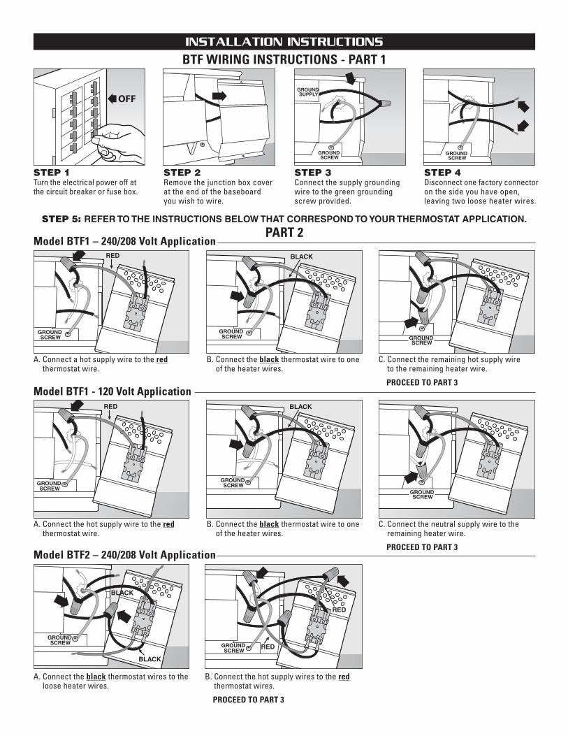
Model BTF2 – 240/208 Volt Application
A. Connect the black thermostat wires to theloose heater wires.
B. Connect the hot supply wires to the redthermostat wires.
PROCEED TO PART 3
STEP 1Turn the electrical power off atthe circuit breaker or fuse box.
STEP 2Remove the junction box coverat the end of the baseboard you wish to wire.
STEP 4Disconnect one factory connectoron the side you have open, leaving two loose heater wires.
PART 2
BTF WIRING INSTRUCTIONS - PART 1
Model BTF1 - 120 Volt Application
A. Connect the hot supply wire to the redthermostat wire.
B. Connect the black thermostat wire to oneof the heater wires.
C. Connect the neutral supply wire to the remaining heater wire.
PROCEED TO PART 3
A. Connect a hot supply wire to the redthermostat wire.
Model BTF1 – 240/208 Volt Application
B. Connect the black thermostat wire to oneof the heater wires.
C. Connect the remaining hot supply wire to the remaining heater wire.
PROCEED TO PART 3
InSTallaTIon InSTrucTIonS
STEP 3Connect the supply groundingwire to the green groundingscrew provided.
GROUND SCREW
GROUND SUPPLY
GROUND SCREW
GROUND SCREW
GROUND SCREW GROUND
SCREW
GROUND SCREW
GROUND SCREW
GROUND SCREW
STEP 5: REFER TO THE INSTRUCTIONS BELOW THAT CORRESPOND TO YOUR THERMOSTAT APPLICATION.

BTF WIRING INSTRUCTIONS CONCLUSION - PART 3
STEP 6Carefully tuck all wires into wiring compartment and attach the thermostat to the baseboard heater.
InSTallaTIon InSTrucTIonS
A. Connect the red thermostatwire labeled L2 to the blackthermostat wire labeled OFFas shown.
Model BTF2 – 120 Volt Application
B. Connect the neutral supplywire to one of the heater wires.
C. Connect the supply hot wire to the remaining redthermostat wire.
D. Connect the remaining black thermostat wire to the remaining heater wire.PROCEED TO PART 3
RED
GROUND SCREW
GROUND SCREW
GROUND SCREW
FIELD WIRING
FIELD WIRING
GROUNDSCREW
GROUNDSCREW
FIELD WIRINGNOTPROVIDED
FIELD WIRINGNOT PROVIDED
FIELD WIRINGNOT PROVIDED
GROUND SCREW
FIELD WIRING
GROUND SCREW
FIELD WIRINGNOT PROVIDEDBTF2
1. Disconnect one factory connector on each baseboard. 2. Connect one supply wire to each red thermostat wire. 3. Connect one black thermostat wire to one wire from each heater. 4. Connect remaining black thermostat wire to the remaining wire from each heater. 5. Connect supply ground wire to both ground screws.
IMPORTANT: Wires shown in illustration are for reference only. All electricalwork and materials must comply with the National Electric Code (NEC) and allstate and local codes.
NOTE: Field wiring is not provided.
BTF11. Disconnect one factory connector on each baseboard. 2. Connect one supply lead to the red thermostat wire. 3. Connect black thermostat wire to one wire on each heater. 4. Connect remaining wire from each heater to the remaining supply lead. 5. Connect supply ground wire to both ground screws.
IMPORTANT: Wires shown in illustration are for reference only. All electricalwork and materials must comply with the National Electric Code (NEC) andall state and local codes.
NOTE: Field wiring is not provided.
More than one baseboard heater can be wired in parallel on same circuit (be sure to check national and local codes for safety requirements). Additional wire is required. Important: When wiring multiple heaters to one thermostat, the baseboards must be in the same room. Maximum amperage rating: 22 amps.
MULTIPLE HEATER WIRING - OPTIONAL
InSTallaTIon InSTrucTIonS
©2009 Cadet Manufacturing Co. Printed in U.S.A. 09/11 #720107
WarranTy
WARRANTYWarranties are non transferable and apply to original consumer only.Warranty terms are set out below.
LIMITED ONE-YEAR WARRANTY: Cadet will repair or replace any Cadetproduct, including thermostats, found to be defective within one yearafter the date of purchase.
THESE WARRANTIES DO NOT APPLY:1. Damage occurs to the product through improper installation or incorrect supply voltage;
2. Damage occurs to the product through improper maintenance, misuse,abuse, accident, or alteration;
3. The product is serviced by anyone other than Cadet;4. If the date of manufacture of the product cannot be determined;5. If the product is damaged during shipping through no fault of Cadet.
6. CADET’S WARRANTY IS LIMITED TO REPAIR OR REPLACEMENT ASSET OUT HEREIN. CADET SHALL NOT BE LIABLE FOR DAMAGESSUCH AS PROPERTY DAMAGE OR FOR CONSEQUENTIAL DAMAGESAND/OR INCIDENTAL EXPENSES RESULTING FROM BREACH OFTHESE WRITTEN WARRANTIES OR ANY EXPRESS OR IMPLIED WARRANTY.
7. IN THE EVENT CADET ELECTS TO REPLACE ANY PART OF YOUR CADETPRODUCT, THE REPLACEMENT PARTS ARE SUBJECT TO THE SAMEWARRANTIES AS THE PRODUCT. THE INSTALLATION OF REPLACEMENTPARTS DOES NOT MODIFY OR EXTEND THE UNDERLYING WARRANTIES.REPLACEMENT OR REPAIR OF ANY CADET PRODUCT OR PART DOESNOT CREATE ANY NEW WARRANTIES.
8. These warranties give you specific legal rights, and you may alsohave other rights which vary from state to state. Cadet neither assumes,nor authorizes anyone to assume for it, any other obligation or liabilityin connection with its products other than as set out herein.
If you believe your Cadet product is defective, please contact CadetManufacturing Co. at 360-693-2505, during the warranty period, for instructions on how to have the repair or replacement processed. Warrantyclaims made after the warranty period has expired will be denied. Products returned without authorization will be refused.
Parts and ServiceVisit http://support.cadetco.com for information on where to obtainparts and service.
Reduce-Reuse-RecycleThis product is made primarily of recyclable materials. You canreduce your carbon footprint by recycling this product at theend of its useful life. Contact your local recycling support centerfor further recycling instructions.
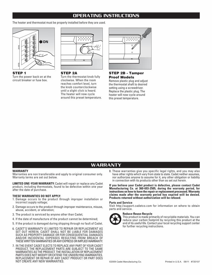
The heater and thermostat must be properly installed before they are used.
operaTIng InSTrucTIonS
STEP 1Turn the power back on at thecircuit breaker or fuse box.
STEP 2ATurn the thermostat knob fullyclockwise. When the roomreaches comfort level, turn the knob counterclockwise until a slight click is heard. The heater will now cyclearound this preset temperature.
STEP 2B - TamperProof ModelsRemove plastic plug and adjustthe thermostat shaft to desiredsetting using a screwdriver. Replace the plastic plug. Theheater will now cycle around this preset temperature.
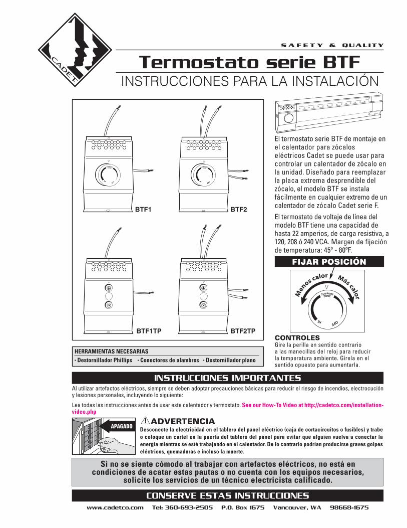
Termostato serie BTF
ADVERTENCIADesconecte la electricidad en el tablero del panel eléctrico (caja de cortacircuitos o fusibles) y trabeo coloque un cartel en la puerta del tablero del panel para evitar que alguien vuelva a conectar la energía mientras se esté trabajando en el calentador. De lo contrario podrían producirse graves golpeseléctricos, quemaduras e incluso la muerte.
Si no se siente cómodo al trabajar con artefactos eléctricos, no está en condiciones de acatar estas pautas o no cuenta con los equipos necesarios,
solicite los servicios de un técnico electricista calificado.
InstruccIones para la InstalacIón
www.cadetco.com Tel: 360-693-2505 p.o. Box 1675 vancouver, Wa 98668-1675
InSTruccIoneS ImporTanTeS
conServe eSTaS InSTruccIoneS
CONTROLESGire la perilla en sentido contrario a las manecillas del reloj para reducir la temperatura ambiente. Gírela en el sentido opuesto para aumentarla.
El termostato serie BTF de montaje enel calentador para zócalos eléctricos Cadet se puede usar paracontrolar un calentador de zócalo enla unidad. Diseñado para reemplazarla placa extrema desprendible delzócalo, el modelo BTF se instalafácilmente en cualquier extremo de uncalentador de zócalo Cadet serie F. El termostato de voltaje de línea delmodelo BTF tiene una capacidad dehasta 22 amperios, de carga resistiva, a120, 208 ó 240 VCA. Margen de fijaciónde temperatura: 45º - 80ºF.
Men
os calor Más calor
BTF1 BTF2
HERRAMIENTAS NECESARIAS• Destornillador Phillips • Conectores de alambres • Destornillador plano
BTF1TP BTF2TP
FIJAR POSICIÓN
Al utilizar artefactos eléctricos, siempre se deben adoptar precauciones básicas para reducir el riesgo de incendios, electrocucióny lesiones personales, incluyendo lo siguiente:
Lea todas las instrucciones antes de usar este calentador y termostato. See our How-To Video at http://cadetco.com/installation-video.php

PASO 1Desconecte la electricidad en el cortacircuito o en la cajade fusibles.
PASO 2Retire la cubierta de la caja de empalmes en el extremo del zócalo que desea cablear.
PASO 4Desenchufe un conector defábrica en el lado que estéabierto, dejando sueltos dosalambres del calentador.
PASO 5 - CONSULTE LAS SIGUIENTES INSTRUCCIONES QUE CORRESPONDAN A SU TERMOSTATO.
PARTE 2 - PASO 5
INSTRUCCIONES PARA EL CABLEADO DEL MODELO BTF - PARTE UNO
Modelo BTF1 - Aplicación de 120 voltios
A. Conecte el cable activo de suministro al alambre rojo del termostato.
B. Conecte el alambre negro del termostatoa uno de los alambres del calentador.
C. Conecte el cable neutro de suministro al otro alambre del calentador.
PROSIGA CON LA 3ª PARTE
A. Conecte un alambre de suministro activoal alambre rojo del termostato.
Modelo BTF1 – Aplicación de 240/208 voltios
B. Conecte el alambre negro del termostatoa uno de los alambres del calentador.
C. Conecte el alambre de suministro activorestante al otro alambre del calentador.
PROSIGA CON LA 3ª PARTE
InSTruccIoneS para la InSTalacIón
PASO 3Conecte el alambre de puestaa tierra del suministro al cableen espiral verde de tierra proporcionado.
GROUND SCREW
GROUND SUPPLY
GROUND SCREW
GROUND SCREW
ROJO
GROUND SCREW
NEGRO
GROUND SCREW
GROUND SCREW
ROJO
GROUND SCREW
NEGRO
GROUND SCREW

PARTE 2 - PASO 5 (CONTINUACIÓN)
CONCLUSIÓN DE LAS INSTRUCCIONES DE CABLEADO PARA EL MODELO BTF - PARTE 3
PASO 6Pliegue cuidadosamente todoslos alambres en el interior del compartimiento y conecte el termostato al calentador de zócalo.
InSTruccIoneS para la InSTalacIón
A. Conecte el alambre rojo deltermostato rotulado L2 alalambre negro rotulado OFF,tal como se aprecia.
Modelo BTF2 – Aplicación de 120 voltios
B. Conecte el alambre neutro de suministro a uno de losalambres del calentador.
C. Conecte el alambre activo de suministro al alambre rojorestante del termostato.
D. Conecte el alambre de suministronegro restante al otro alambredel calentador.
PROSIGA CON LA 3ª PARTE
GROUND SCREW
NEGRO
NEGRO
GROUNDSCREW
GROUND SCREW
GROUNDSCREW
GROUNDSCREW
Modelo BTF2 – Aplicación de 240/208 voltios
A. Conecte los alambres negros del termostatoa los alambres sueltos del calentador.
B. Conecte los cables activos de suministro a los alambres rojos del termostato.
PROSIGA CON LA 3ª PARTE
FIELD WIRINGNOT PROVIDED
GROUNDSCREW
GROUNDSCREW
FIELD WIRINGNOTPROVIDED
FIELD WIRINGNOT PROVIDED
NEGRO
ROJO
FIELD WIRINGNOT PROVIDED
FIELD WIRINGNOT PROVIDED
GROUND SCREW
FIELD WIRING
GROUND SCREW
FIELD WIRINGNOT PROVIDED
ROJO
ROJO
NEGRO
NEGRO
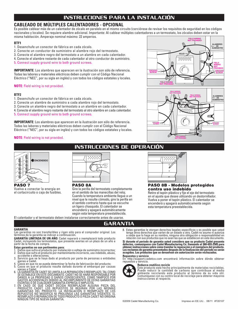
BTF21. Desenchufe un conector de fábrica en cada zócalo. 2. Conecte un alambre de suministro a cada alambre rojo del termostato. 3. Conecte un alambre negro del termostato a un alambre en cada calentador. 4. Conecte el alambre negro restante del termostato al otro alambre en cada calentador.5. Connect supply ground wire to both ground screws.
IMPORTANTE: Los alambres que aparecen en la ilustración son sólo de referencia.Todas las labores y materiales eléctricos deben cumplir con el Código NacionalEléctrico (“NEC”, por su sigla en inglés) y con todos los códigos estatales y locales.
NOTE: Field wiring is not provided.
BTF11. Desenchufe un conector de fábrica en cada zócalo. 2. Conecte un conductor de suministro al alambre rojo del termostato. 3. Conecte el alambre negro del termostato a un alambre en cada calentador. 4. Conecte el alambre restante de cada calentador al otro conductor de suministro. 5. Connect supply ground wire to both ground screws.
IMPORTANTE: Los alambres que aparecen en la ilustración son sólo de referencia.Todas las labores y materiales eléctricos deben cumplir con el Código NacionalEléctrico (“NEC”, por su sigla en inglés) y con todos los códigos estatales y locales.
NOTE: Field wiring is not provided.
Es posible cablear más de un calentador de zócalo en paralelo en el mismo circuito (cerciórese de revisar los requisitos de seguridad en los códigosnacionales y locales). Se requiere alambre adicional. Importante: Al cablear múltiples calentadores a un termostato, los zócalos deben estar en lamisma habitación. Amperaje nominal máximo: 22 amperios.
CABLEADO DE MÚLTIPLES CALENTADORES - OPCIONAL
©2009 Cadet Manufacturing Co. Impreso en EE.UU.. 08/11 #720107
InSTruccIoneS para la InSTalacIón
garanTIaGARANTIALas garantías no son transferibles y rigen sólo para el comprador original. Lostérminos de la garantía se indican a continuación.GARANTÍA LIMITADA DE UN AÑO: Cadet reparará o reemplazará todo productoCadet, incluyendo los termostatos, que presente averías en un plazo de un año apartir de la fecha de compra.Estas garantías no son pertinentes para:1. Daños que sufra el producto por instalación o voltaje de suministro incorrectos;2. Daños que sufra el producto por mantenimiento incorrecto, uso indebido, abuso,accidente o alteraciones;
3. Servicio que se le haya dado al producto por parte de personas o entidadesajenas a Cadet.
4. Casos en que no se pueda determinar la fecha de fabricación del producto;5. Casos en que el producto resulte dañado durante el embarque por causasajenas a Cadet;
6. LA GARANTÍA DE CADET SE LIMITA A LA REPARACIÓN O REEMPLAZO, TAL COMOSE ESTABLECE EN ESTE DOCUMENTO. CADET NO SE HARÁ RESPONSABLE PORDAÑOS A LA PROPIEDAD O DAÑOS CONSECUENTES, COMO TAMPOCO PORGASTOS ACCIDENTALES DEBIDO AL INCUMPLIMIENTO DE ESTAS GARANTÍASESCRITAS O DE CUALQUIER GARANTÍA EXPRESA O IMPLÍCITA.
7. EN CASO DE QUE CADET DECIDA REEMPLAZAR ALGUNA PIEZA DELPRODUCTO CADET, LOS REPUESTOS SE REGIRÁN POR LAS MISMASGARANTÍAS DEL PRODUCTO. LA INSTALACIÓN O REEMPLAZO DE LOSREPUESTOS NO MODIFICA NI PROLONGA LAS GARANTÍAS VIGENTES. ELREEMPLAZO O REPARACIÓN DE TODO PRODUCTO O PIEZA CADET NO ORIGINANINGÚN TIPO DE NUEVA GARANTÍA.
8. Estas garantías le otorgan derechos legales específicos y es posible que ustedtenga otros derechos que varíen de un estado a otro. Cadet no asume ni autorizaa nadie que lo haga en su nombre, ninguna otra obligación o responsabilidad enrelación con sus productos que no sean las que se establecen en este documento.
Si durante el período de garantía usted considera que su producto Cadet presentadefectos, comuníquese con Cadet Manufacturing Co. llamando al 360-693-2505 paraobtener instrucciones sobre cómo tramitar la reparación o el reemplazo del producto.Los reclamos de garantía presentados después de la finalización del período no seránacogidos. Los productos que se devuelvan sin autorización serán rechazados.Repuestos y servicioEn http://support.cadetco.com encontrará información sobre dónde obtenerrepuestos y servicio.
Reduzca-reutilice-recicleEste producto está hecho principalmente de materiales reciclables.Puede reducir la cantidad de carbono que contribuye al medio ambiente reciclando este producto al término de su vida útil. Comuníquese con su centro local de reciclaje para obtener mayoresinstrucciones al respecto.
El calentador y el termostato deben instalarse correctamente antes de usarse.
InSTruccIoneS De operacIón
PASO 7Vuelva a conectar la energía enel cortacircuito o caja de fusibles.
PASO 8AGire la perilla del termostato completamenteen el sentido de las manecillas del reloj.Cuando la temperatura ambiente llegue a unnivel que le resulte cómodo, gire la perilla enel sentido contrario hasta que se escucheun ligero chasquido. El calentador seencenderá y apagará automáticamentesegún esta temperatura preestablecida.
PASO 8B - Modelos protegidoscontra uso indebidoRetire el tapón plástico y fije el eje del termostatoen el ajuste que desee utilizando un destornillador.Vuelva a poner el tapón plástico. El calentador seencenderá y apagará automáticamente segúnesta temperatura preestablecida.