bs 10175 2001 investigation of potentially contaminated site
DESCRIPTION
Investigation of potentially contaminated siteTRANSCRIPT
|||||||||||||||||||||||||||||||||||||||||||||||||||||||||||||||||||||||||||||||||||||||||||||||||||||||||||||||||||||||||||||||||
BRITISH STANDARD BS 10175:2001
ICS 13.080.01; 19.040; 91.200
NO COPYING WITHOUT BSI PERMISSION EXCEPT AS PERMITTED BY COPYRIGHT LAW
Investigation ofpotentiallycontaminated sites ÐCode of practice

This British Standard, havingbeen prepared under thedirection of the Health andEnvironment Sector Committee,was published under theauthority of the StandardsCommittee and comes into effecton 15 January 2001
BSI 01-2001
The following BSI referencesrelate to the work on thisstandard:Committee reference EH/4/2Draft for comment 98/564053 DC
ISBN 0 580 33090 7
BS 10175:2001
Amendments issued since publication
Amd. No. Date Comments
Committees responsible for thisBritish Standard
The preparation of this British Standard was entrusted by Technical CommitteeEH/4, Soil quality, to Subcommittee EH/4/2, Sampling, upon which the followingbodies were represented:
AEA Technology
Association of Consulting Scientists
Association of Geotechnical and Geoenvironmental Special
Association of Metropolitan Authorities
Association of Public Analysts
British Society of Soil Science
Chartered Institute of Environmental Health
Chartered Institution of Water and Environmental Management
Chemical Industries Association
Environment Agency
Environmental Industries Commission Ltd.
Food Standards Agency
Health and Safety Executive
Institute of Chemical Engineers
Institute of Civil Engineers
Institute of Wastes Management
Laboratory of the Government Chemist
Macaulay Land Use Research Institute
National House Building Council
Royal Society of Chemistry
Society of Chemical Industry
Soil Survey and Land Research Centre
University of Glasgow
Water Research Centre
BS 10175:2001
BSI 01-2001 i
Contents
Page
Committees responsible Inside front cover
Foreword iii
Introduction 1
1 Scope 1
2 Normative references 2
3 Terms and definitions 2
4 Setting the objectives of an investigation 4
4.1 General 4
4.2 Guidance on drawing up detailed objectives 4
4.3 Examples of typical investigations and applications 6
5 Establishing an investigation strategy 6
5.1 General 6
5.2 Outline of strategy 6
5.3 Preliminary investigation 8
5.4 Exploratory investigation 8
5.5 Main investigation 9
5.6 Supplementary investigation 9
5.7 Investigation strategy 10
6 Preliminary investigation 11
6.1 General 11
6.2 Data collection 12
6.3 Interpretation and reporting 15
7 Design and planning of field investigations 16
7.1 General 16
7.2 Integrated investigations 17
7.3 Personnel and environmental protection 17
7.4 Pre-investigation considerations 17
7.5 Method of field investigation 18
7.6 Sampling strategies 19
7.7 Design of testing requirements 28
7.8 Quality assurance (QA) and quality control (QC) 29
8 Fieldwork 29
8.1 General 29
8.2 Techniques 29
8.3 Sampling 38
8.4 On-site testing 44
8.5 Sample containers 45
8.6 Sample labelling, preservation and handling 46
8.7 Sampling report 46
9 Off-site analysis of samples 47
9.1 General 47
9.2 Choice of laboratory 47
9.3 The assessment and control of errors in sub-sampling and analysis 48
9.4 Selection of contaminants for analysis 48
9.5 Preparation of samples for analysis 49
9.6 Analysis of samples 49
BS 10175:2001
ii BSI 01-2001
9.7 Geotechnical and other testing of soils 51
10 Reports 51
10.1 General 51
10.2 Preliminary investigation report 51
10.3 Intrusive investigation report 52
Annex A (informative) Examples of site investigations 55
Annex B (informative) Health and safety in site investigations 65
Annex C (informative) Typical gas monitoring well construction 67
Annex D (informative) Collection of a representative sample by means of aªnine point sampleº 68
Annex E (informative) Suitability of sample containers 69
Bibliography 71
Figure 1 Ð Schematic approach to site investigation 7
Figure 2 Ð Considerations in the selection of intrusive investigation method 38
Figure A.1 Ð Site plan: Example 1 56
Figure A.2 Ð Site plan: Example 2 61
Figure C.1 Ð Typical gas monitoring well construction 67
Figure D.1 Ð Nine point sampling pattern 68
Table 1 Ð Typical objectives of the different phases of an investigation 5
Table 2 Ð Preliminary investigation 11
Table 3 Ð Types of available information 12
Table 4 Ð Phasing groundwater investigations 23
Table 5 Ð Methods of non-intrusive investigation 30
Table 6 Ð Methods of intrusive investigation 34
Table 7 Ð Selection of suitable investigation method for different ground types 39
Table 8 Ð Physical requirements of different investigation methods 39
Table 9 Ð Types of sample 41
Table B.1 Ð Health and safety measures for site investigations 66
Table E.1 Ð Suitability of sample containers 69
BS 10175:2001
BSI 01-2001 iii
Foreword
This British Standard has been prepared by EH/4/2, Sampling. It supersedesDD 175:1988 which is withdrawn.
It is now consistent with current methodologies and has been updated considerablysince the publication of DD 175.
Attention is drawn to the following primary legislation and the statutory regulationsmade under these various acts and under European Directives enacted that arerelevant to safety, environmental protection and construction works:
Ð The Factories Act, 1961 [1];
Ð Offices, Shops and Railway Premises Act, 1963 [2];
Ð The Health and Safety at Work, etc. Act, 1974 [3];
Ð The Control of Pollution Act 1974 and The Control of Pollution (Amendment)Act, 1989 [4];
Ð The Water Act 1989 [5];
Ð The Environmental Protection Act, 1990 [6];
Ð The Water Resources Act, 1991 [7];
Ð The Environment Act, 1995 [8];
Ð The Town and Country Planning Act [41];
Ð The Building Control Act [42];
Ð The Construction Design and Management Regulations (CDM regulations),1995 [9];
Ð Control of Substances Hazardous to Health Regulations, 1988 [10];
DETR/Environment Agency are currently developing a Handbook of Model Proceduresfor the Management of Contaminated Land. It is intended to review this code ofpractice when the Handbook has been published.
A British Standard does not purport to include all the necessary provisions of acontract. Users of British Standards are responsible for their correct application.
As a code of practice, this British Standard takes the form of guidance andrecommendations. It should not be quoted as if it were a specification and particularcare should be taken to ensure that claims of compliance are not misleading.
Compliance with a British Standard does not of itself confer immunityfrom legal obligations.
Summary of pages
This document comprises a front cover, an inside front cover, pages i to iv, pages 1to 75 and a back cover.
The BSI copyright notice displayed in this document indicates when the document waslast issued.

iv blank
BS 10175:2001
BSI 01-2001 1
IntroductionThe guidance in this British Standard is applicable to the investigation of all potentially contaminated sitesand also to land with naturally enhanced concentrations of potentially harmful substances.
The management of contaminated land involves identifying risks due to the presence of contaminants, inorder that appropriate action can be taken. The risk assessment of a potentially contaminated site requiresinformation to characterize the contamination status. This information is gathered by a process of siteinvestigation as set out in this standard. The information required comprises:
Ð details of the historical setting of the site and the potential for the presence of contaminants;
Ð identification of who or what could be affected by the contaminants (i.e. receptors);
Ð information on the pathways by which contaminants could migrate or come into contact withreceptors (including details of any physical characteristics of the site that will affect contaminantmovement).
The results of the investigation should define all known aspects of the site that could impinge upon or affectthe contaminant Ð pathway Ð receptor scenario and is referred to as the conceptual model.
The conceptual model, resulting from the preliminary investigation (desk study), is used to focus subsequentinvestigations, where these are necessary, to meet the objectives of the overall investigation. However, theuse of the conceptual model to assess the requirement for remedial action is a part of the risk assessmentprocess. Guidance on how to carry out a risk assessment is outside the scope of this standard. For guidanceon risk assessment see CIRIA publication SP103 [11] and CIWEM publication [47].
NOTE 1 Guidance on the management of contaminated land is in the process of preparation and will be published by the Departmentof the Environment, Transport and Regions (DETR) and the Environment Agency [12]. When published that document will also provideguidance on the assessment of contaminated land. It can be used in conjunction with the recommendations given in this standard.Particular attention is drawn to Part III, Procedure for risk assessment.
NOTE 2 The process of investigation is likely to involve a number of stages each with different detailed objectives and utilizing a rangeof technologies. At the end of each stage the information obtained should be reviewed to determine if the objectives have been met andif there is a need for further investigation. Where further investigation is necessary the design of the next stage should be based on andutilize the information previously obtained.
NOTE 3 Some requirements for investigation may lie beyond the needs of a risk assessment, for example a validation-sampling schemeor the selection and detailed design of a remediation scheme. In such situations it should be possible to use the procedures given in thisBritish Standard to design the relevant investigation.
1 ScopeThis British Standard provides guidance on, and recommendations for, the investigation of potentiallycontaminated land or land with naturally enhanced concentrations of potentially harmful materials, todetermine or manage the ensuing risks. It covers:
Ð setting the objectives of an investigation;
Ð setting a strategy for the investigation;
Ð designing the different phases of the investigation;
Ð sampling and on-site testing;
Ð laboratory analysis;
Ð reporting;
in order to obtain scientifically robust data on soil, groundwater, surface water and ground gascontamination.
It is intended for use by those with some understanding of the risk-based approach to sites and siteinvestigations.
The relevant guidance and recommendations within this standard should be selected to ensure that theobjectives of an investigation are achieved and that adequate data for the risk assessment are obtained.However, it is not feasible to provide detailed guidance for every possible investigation scenario.
This British Standard does not give recommendations on certain constraints or problems that can affect asite, such as geotechnical aspects, [which are covered by BS 5930 (see 7.2)], or the legal aspects, includingthe need for licences, permits, etc.
It does not include any procedures for the formal assessment of the potential risks posed by contaminatedland. However, attention is drawn to the guidance published by CIRIA in SP103 [11] and CIWEM [47].
NOTE The Handbook of Model Procedures [12] which is in the process of development by the DETR and the Environment Agency, willalso be a source of guidance on risk assessment when published.
When relevant, this standard can be used in conjunction with other standards and codes of practice forcombined investigations, such as in conjunction with geotechnical investigations.
2 BSI 01-2001
BS 10175:2001
2 Normative referencesThe following normative documents contain provisions, which, through reference in this text, constituteprovisions of this British Standard. For dated references, subsequent amendments to, or revisions of, any ofthese publications do not apply. For undated references, the latest edition of the publication referred toapplies.
BS 1017 (all parts), Sampling of coal and coke.
BS 1377 (all parts), Methods of test for soils for civil engineering purposes.
BS 1747 (all parts), Methods for measurement of air pollution.
BS 5930:1999, Code of practice for site investigations.
BS 6068-6.4, Water quality. Sampling. Guidance on sampling from lakes, natural and man-made.
BS 6068-6.5, Water quality. Sampling. Guidance on sampling of drinking water and water used for foodand beverage processing.
BS 6068-6.6, Water quality. Sampling. Guidance on sampling of rivers and streams.
BS 6068-6.11, Water quality. Sampling. Guidance on sampling of groundwaters.
BS 6068-6.12, Water quality. Sampling. Guidance on sampling of bottom sediments.
BS 6068-6.14, Water quality. Sampling. Guidance on quality assurance of environmental water samplingand handling.
BS 6069, (all parts), Characterization of air quality.
BS 6187, Code of practice for demolition.
BS 7755 (all parts), Soil quality Chemical methods.
BS 8855 (all parts), Soil analysis.
BS EN 25667-1, Water quality: Sampling Ð Part 1: Guidance on the design of sampling programmes (dualnumbered as BS 6068-6.1).
BS EN 25667-2, Water quality: Sampling Ð Part 2: Guidance on sampling techniques (dual numbered asBS 6068-6.2).
BS EN ISO 5667-3, Water quality: Sampling Ð Part 3: Guidance on the preservation and handling ofsamples (dual numbered as BS 6068-6.3).
3 Terms and definitionsFor the purposes of this British Standard the following terms and definitions apply.
3.1
accuracy
level of agreement between true value and observed value
3.2
conceptual model
textual and/or schematic hypothesis of the nature and sources of contamination, potential migrationpathways (including description of the ground and groundwater) and potential receptors, developed on thebasis of the information from the preliminary investigation and refined during subsequent phases ofinvestigation and which is an essential part of the risk assessment process
NOTE The conceptual model is initially derived from the information obtained by the preliminary investigation. This conceptual modelis used to focus subsequent investigations, where these are considered to be necessary, in order to meet the objectives of theinvestigations and the risk assessment. The results of the field investigation can provide additional data that can be used to furtherrefine the conceptual model.
3.3
contamination
presence of a substance which is in, on or under land, and which has the potential to cause harm or tocause pollution of controlled water
NOTE 1 There is no assumption in this definition that harm results from the presence of the contamination.
NOTE 2 Naturally enhanced concentrations of harmful substances can fall within this definition of contamination.
BS 10175:2001
BSI 01-2001 3
3.4
controlled water
inland freshwater (any lake, pond or watercourse above the freshwater limit), water contained inunderground strata and any coastal water between the limit of highest tide or the freshwater line to the threemile limit of territorial watersNOTE See Section 104 of The Water Resources Act 1991 [7].
3.5
harm
adverse effect on the health of living organisms, or other interference with ecological systems of which theyform part, and, in the case of humans, including property
3.6
hazard
inherently dangerous quality of a substance, procedure or event
3.7
pathway
mechanism or route by which a contaminant comes into contact with, or otherwise affects, a receptor
3.8
precision
level of agreement within a series of measurements of a parameter
3.9
receptor
persons, living organisms, ecological systems, controlled waters, atmosphere, structures and utilities thatcould be adversely affected by the contaminant(s)
3.10
risk
probability of the occurrence of, and magnitude of the consequences of, an unwanted adverse effect on areceptor
3.11
risk assessment
process of establishing, to the extent possible, the existence, nature and significance of risk
3.12
sampling
methods and techniques used to obtain a representative sample of the material under investigation
3.13
soil
upper layer of the earth's crust composed of mineral parts, organic substance, water, air and living matter
[BS 7755-1.4:2000]NOTE For the purposes of this British Standard the term soil has the meaning ascribed to it through general use in civil engineeringand includes topsoil and subsoils; deposits such as clays, silt, sand, gravel, cobbles, boulders and organic deposits such as peat; andmaterial of natural or human origin (e.g. fills and deposited wastes). The term embraces all components of soil, including mineralmatter, organic matter, soil gas and moisture, and living organisms.
3.14
source
location from which contamination is, or was, derivedNOTE This could be the location of the highest soil or groundwater concentration of the contaminant(s).
3.15
target
see receptor
3.16
uncertainty
parameter, associated with the result of a measurement, that characterizes the dispersion of the values thatcould reasonably be attributed to the measurement
4 BSI 01-2001
BS 10175:2001
4 Setting the objectives of an investigation
4.1 General
The objective of a site investigation will be to gather the information needed to form a conceptual model inorder to be in a position to assess the presence and significance of contamination of land (or in the case ofnaturally occurring material, the significance of the concentrations present). The resultant information thenenables the risk assessment to be carried out to conclusions in which an acceptable degree of confidencecan be placed.
At any of the various stages of an investigation, the overall objectives will be to characterize thecontaminants present and to identify pathways and receptors for the purposes of the risk assessment. Theinformation required in order to carry out the risk assessment to a robust conclusion should be identifiedbefore designing or planning an investigation.
The investigation of land for the presence of contamination or naturally occurring enhanced concentrationsof harmful substances is driven by the need to assess the risks associated with a site. The objectives of arisk assessment, and a site investigation, are determined by the purpose for which the risk assessment isrequired. The risk assessment that is identified as fulfilling the requirements of the purchaser of that process(the client) determines the objectives of a site investigation.
The objectives of a site investigation will vary, depending upon the stage in the process that has beenreached, and the underlying intentions for the land involved. Objectives may for example be to:
Ð define or clarify a conceptual model;
Ð support a risk assessment;
Ð provide data for the design of remedial works;
Ð benchmark the contamination status of a site.
4.2 Guidance on drawing up detailed objectives
The following guidance applies when drawing up the objectives.
a) The questions that information from the investigation will be used to resolve should be identified.
b) The information that is needed, the measurements required, the level of detail and the accuracy that isrequired to resolve the questions should be determined.
c) The investigation boundaries, both spatially and temporally, should be defined.
d) In the context of providing information for a risk assessment, the purpose of the risk assessment shouldbe defined.
As information is developed during an investigation, it is essential to consider the impact on the objectivesand to review the objectives to determine if these require modification or extension.
The formulation and refinement of a conceptual model is always one of the objectives and, as moreinformation is obtained, the model should be reviewed and revised in the context of the additionalinformation.
Table 1 sets out typical detailed objectives that can be associated with different stages of an investigation.
The selection and design of remedial measures may require additional information, for example geotechnicaldata.
Although the general objectives will always be similar for the risk assessment process, the detailedobjectives and the amount of information which will be adequate to give the subsequent assessmentsufficient confidence will vary according to the reason for carrying out the assessment and the investigation.
Further information on setting objectives can be obtained from EPA QA/G-4 [11].
NOTE In some circumstances benefits can be gained from investigations that combine the needs of contamination and geotechnicalobjectives. However, the use of an integrated investigation should not be allowed to compromise the objectives or requirements ofeither investigation (see 7.2).
BS 10175:2001
BSI 01-2001 5
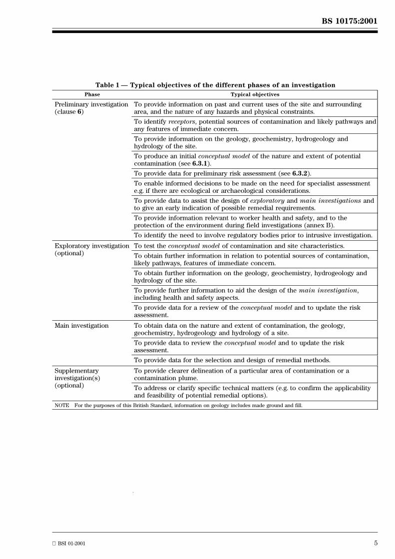
Table 1 Ð Typical objectives of the different phases of an investigation
Phase Typical objectives
Preliminary investigation(clause 6)
To provide information on past and current uses of the site and surroundingarea, and the nature of any hazards and physical constraints.
To identify receptors, potential sources of contamination and likely pathways andany features of immediate concern.
To provide information on the geology, geochemistry, hydrogeology andhydrology of the site.
To produce an initial conceptual model of the nature and extent of potentialcontamination (see 6.3.1).
To provide data for preliminary risk assessment (see 6.3.2).
To enable informed decisions to be made on the need for specialist assessmente.g. if there are ecological or archaeological considerations.
To provide data to assist the design of exploratory and main investigations andto give an early indication of possible remedial requirements.
To provide information relevant to worker health and safety, and to theprotection of the environment during field investigations (annex B).
To identify the need to involve regulatory bodies prior to intrusive investigation.
Exploratory investigation(optional)
To test the conceptual model of contamination and site characteristics.
To obtain further information in relation to potential sources of contamination,likely pathways, features of immediate concern.
To obtain further information on the geology, geochemistry, hydrogeology andhydrology of the site.
To provide further information to aid the design of the main investigation,including health and safety aspects.
To provide data for a review of the conceptual model and to update the riskassessment.
Main investigation To obtain data on the nature and extent of contamination, the geology,geochemistry, hydrogeology and hydrology of a site.
To provide data to review the conceptual model and to update the riskassessment.
To provide data for the selection and design of remedial methods.
Supplementaryinvestigation(s)(optional)
To provide clearer delineation of a particular area of contamination or acontamination plume.
To address or clarify specific technical matters (e.g. to confirm the applicabilityand feasibility of potential remedial options).
NOTE For the purposes of this British Standard, information on geology includes made ground and fill.
6 BSI 01-2001
BS 10175:2001
4.3 Examples of typical investigations and applications
The following examples are typical of the types of investigations that are carried out and the types ofapplications for which they are used.
a) Objectives of investigation: to provide information for the development of an initial conceptual model ofthe site and the potential contaminant-pathway-receptor scenarios, and the assessment of potential risk(desk study, see Table 1 and preliminary investigation, clause 6).
NOTE Different conceptual models may be formulated for different areas and development stages of a site (see 5.3).
Typical application: the first stage in any contaminated land assessment. There may be a need for furtherinvestigation to confirm the conceptual model postulated, or the information obtained may be consideredadequate for the decisions to be made, e.g. pre-purchase assessment.
b) Objectives of investigation: to confirm a conceptual model and confirm whether proposedcontaminant-pathway-receptor scenarios exist (exploratory investigation, see Table 1, subclauses 5.4and 5.7, and clauses 7 and 8).
Typical application: to provide more information and better definition of the potential contaminationidentified in a) e.g. pre-purchase survey and due diligence audits.
c) Objectives of investigation: to provide sufficient information so that, wherecontaminant-pathway-receptor scenarios exist, the risks can be quantified (main investigation, seeTable 1, subclauses 5.5 and 5.7, and clauses 7 and 8).
Typical application: to enable the identification and assessment of risks to those working on a site, tosubsequent users, property or the environment, so that risks to these receptors can be managed, e.g. wherea site is to be redeveloped.
d) Objectives of investigation: to provide information for the assessment of potential for future liabilities,for example due to contamination migration or a need for remediation when the land is redeveloped(can be exploratory or main investigation).
Typical application: used for the pre-purchase investigation of a business acquisition, which will continueto operate, i.e. part of a due diligence audit.
e) Objectives of investigation: to enable an assessment to be made of whether any significant pollutantlinkages exist at the site which might lead to a requirement for remediation and the potential associatedcosts (can be exploratory or main investigation).
Typical application: part of the pre-purchase acquisition review or portfolio management action,considering the site in the context of Part 11A of the Environmental Protection Act 1990 [6].
f) Objectives of investigation: to provide information for the assessment of contamination and thedetermination of the cost of remediation for a proposed use (main investigation).
Typical application: where land is already owned and it is necessary to determine the contaminationstatus, and hence the remediation that is necessary to bring it into beneficial use or for a specificredevelopment.
g) Objectives of investigation: to establish the current contamination status of a site.
Typical application: benchmarking for the purposes of IPPC, validation after remediation, benchmarkingfor insurance, financial or legal reasons.
5 Establishing an investigation strategy
5.1 General
Having determined the objectives of the investigation, a strategy needs to be developed to obtainappropriate, suitably robust and defensible data.
The different objectives of site investigations will, in particular, influence the selection of sampling locations,the number of samples analysed and to a lesser extent the analytical requirements.
5.2 Outline of strategy
The identification and delineation of contamination, the identification of areas of naturally enhancedconcentrations of harmful substances and, particularly, the assessment of human and environmental risk canbe complex. Because of this complexity, a site investigation should be carried out in a series of consecutivesteps, each step designed to achieve specific objectives. The process of identifying and quantifying risks is anongoing and iterative process. Several stages may be necessary to obtain sufficient relevant data tocharacterize potential contaminant-pathway-receptor scenarios.
The strategy should incorporate review stages so that data obtained is considered and decisions taken on theimplications as the investigation proceeds.
BS 10175:2001
BSI 01-2001 7
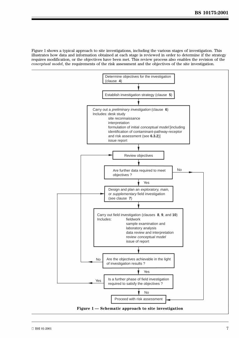
Figure 1 shows a typical approach to site investigations, including the various stages of investigation. Thisillustrates how data and information obtained at each stage is reviewed in order to determine if the strategyrequires modification, or the objectives have been met. This review process also enables the revision of theconceptual model, the requirements of the risk assessment and the objectives of the site investigation.
Determine objectives for the investigation (clause 4)
Establish investigation strategy (clause 5)
Carry out a preliminary investigation (clause 6)Includes: desk study
site reconnaissance interpretation formulation of initial conceptual model [including identification of contaminant-pathway-receptor and risk assessment (see 6.3.2)] issue report
Review objectives
Are further data required to meetobjectives ?
Design and plan an exploratory, main,or supplementary field investigation(see clause 7)
Carry out field investigation (clauses 8, 9, and 10)Includes: fieldwork
sample examination and laboratory analysis data review and interpretationreview conceptual modelissue of report
Are the objectives achievable in the lightof investigation results ?
Is a further phase of field investigationrequired to satisfy the objectives ?
Proceed with risk assessment
No
Yes
Yes
No
No
Yes
Figure 1 Ð Schematic approach to site investigation
8 BSI 01-2001
BS 10175:2001
A strategic approach to the design of the site investigation will require careful consideration of the following:
Ð the objectives of the work;
Ð the site constraints;
Ð the available investigation techniques,
in order to select a process of investigation that will conform to all the requirements of the objectives asclosely as possible.
For a pre-purchase assessment of land (to determine the degree of contamination and the potentialremediation requirements), there can be a balance to be struck between the costs of the investigation andthe amount of data to be collected since, if the project does not proceed, the cost of the investigation cannotbe recouped by the client.
5.3 Preliminary investigation
The first step in the investigation process will always be a preliminary investigation (desk study)(see clause 6). The methodology for carrying out a fully comprehensive preliminary investigation is based onreference to historical records (6.2.1.2.1) and other sources of information (6.2.1.2.2), consultation withrelevant sources (6.2.1.5) and a site reconnaissance (6.2.2). However, the objectives may not require suchdetail, in which case the strategy will identify what aspects of the preliminary investigation are necessaryand those which do not need to be addressed.
For example, it may not be considered necessary to carry out a site reconnaissance (6.2.2) if it is knownthat the site is totally covered by recent building.
Where aspects of a preliminary investigation are not to be included, these should be agreed with the clientand any limitations on the final assessment as a result of the omissions should be clearly understood by allthe parties involved.
Even where information relevant to the preliminary investigation is already available, this should still beformalized into a preliminary investigation report.
The strategy should provide for a review of the information obtained on conclusion of the preliminaryinvestigation to determine if the objectives have been achieved and if there is a need for proceeding withfurther investigation (6.3.3).
The output from the preliminary investigation should include the initial conceptual model (6.3.1) and apreliminary risk assessment (6.3.2) based on the information available. This may indicate that different areasof the site have different characteristics; for example some areas may be made ground and other areasnatural ground: some areas may be potentially subject to contamination due to volatile organic compoundsand other areas may be subject to potential inorganic contamination or there may be no indication of anycontaminative use.
Where logical and appropriate the site may be divided into different zones or areas with differentcontamination potential, contaminant-pathway-receptor scenarios and conceptual models. Thus it will berealistic to have different requirements for the further investigation of different areas of the site.
5.4 Exploratory investigation
This may involve the collection and analysis of soil (7.6.2 and 8.3.2), surface water (7.6.3.8),groundwater (7.6.3 and 8.3.3), and soil gas (7.6.4 and 8.3.4) samples in order to obtain the informationappropriate to the objectives.
An exploratory investigation may be used to obtain an indication that the initial conceptual model isgenerally correct before carrying out a main investigation to provide detailed confirmation.
Where the conceptual model output from the preliminary investigation identifies the likelihood of localizedsources of contamination, e.g. fuel storage tanks, and there is inadequate information to do more thanªguesstimateº the direction of groundwater flow, an appropriate strategy would be to carry out an intrusiveexploratory investigation to provide information on the actual presence of contamination at the suspectlocations and also to provide information on the water table in terms of groundwater flow and groundwaterquality. Thus an exploratory investigation will tend to use targeted sampling locations (see 7.6.2.2).
It may be appropriate to consider the use of a non-intrusive investigation technique (see 7.5, 8.2 and Table 5)as an aid for locating below ground structures or other features of the site prior to intrusive examination aspart of the main investigation.
BS 10175:2001
BSI 01-2001 9
It may become apparent as a result of the exploratory investigation that, for example, the contaminationpattern is more complex or concentrations and/or extent are greater than anticipated. In such situations theinformation obtained is likely to be inadequate to make decisions with the necessary degree of confidence. Itwill be necessary to review the initial conceptual model and the requirements of the risk assessment. It islikely that it will be necessary to review the preliminary investigation information, and to carry out furtherinvestigatory work in order to refine the conceptual model and to provide adequate robust information forthe risk assessment.
The review of the information obtained from the exploratory investigation may be such that a decision maybe made that there is no need for further investigation. Alternatively, the information obtained may be usedto design specific aspects of the main investigation.
5.5 Main investigation
This will involve the collection and analysis of samples of soil (7.6.2 and 8.3.2), surface water (7.6.3),groundwater (7.6.3 and 8.3.3), and soil gas (7.6.4 and 8.3.4) in order to obtain all the information necessaryfor the assessment of human and environmental risks. The detail required will depend upon the objectives ofthe investigation.
The further information and data should enable a full assessment of the risks presented by the contaminationand also enable any containment or remediation actions to be properly designed with more accuratequantification of the costs.
This will require a carefully designed investigation, which should take into account the informationdeveloped in the earlier stages of investigation, and the objectives at this stage of the work.
During the subsequent assessment of risks and hazards, all possible migration routes relevant to thecontamination should be considered and a four-dimensional picture (in space and time) of the contaminationestablished. These requirements should be borne in mind when carrying out the design of the maininvestigation since to reach defensible conclusions, detailed knowledge of physical and chemical soilproperties and of the local hydrology is essential (see Table 1).
The amount and nature of the information required from the main investigation will vary depending on thenature of the site, and the possible requirements for remedial action (see 5.3 on the need for differinginvestigations on different areas or zones of a site). The implications of the decisions on what actions shouldbe implemented on a site will vary from site to site, and the amount and quality of the information will varyaccording to the confidence required in the decision making process. All parties involved in the decisionmaking process should be kept fully informed as information is produced to check that the information issufficient for the purpose intended.
The main investigation may involve some further targeted sampling points (for example at areas of specificconcern in relation to potential contamination, or to achieve delineation of contaminationconfirmed/detected in the exploratory investigation). The greater proportion of the sampling points in amain investigation are normally non-targeted (see 7.6.2.3).
5.6 Supplementary investigation
A review of the outcome of the main investigation may still identify aspects where there is a deficiency ofinformation. For example, to improve the accuracy of costing for a remediation may require further samplingto delineate an area of contamination or a contamination plume or more monitoring wells may be necessaryto confirm the direction of groundwater flow. Where such deficiencies are identified, a supplementaryinvestigation will be necessary. This will be designed to produce quite specific information and will thereforeutilize targeted sampling (7.6.2.2).
When considering the costs of remediation it is likely that the collection of more detailed data will benecessary. Each remediation method (excavation, cover systems, in-ground barriers, biological treatment,thermal treatment, etc.) is likely to have its own data requirements and a supplementary investigation will benecessary to produce this additional data. Where contaminated soil or other materials are to be processedthis may require characterization of the bulk of material including assessment of variability. It may benecessary to investigate the material or site more closely than for risk assessment and this may also haveeconomic advantages, for example where discrimination between material requiring different treatmentlevels, types of treatment or disposal off- or on-site is made easier.
The on-going monitoring of groundwater and ground gas wells is also sometimes classed as supplementaryinvestigation. The situation may arise where the results of monitoring as part of the main investigationindicate that longer term monitoring will be beneficial in enabling a better assessment of risks to beachieved.
Validation sampling carried out to confirm the efficacy of remediation may incorporate some targetedsampling (7.6.2.2) located at areas of specific remediation but will generally be non-targeted (7.6.2.3).
10 BSI 01-2001
BS 10175:2001
5.7 Investigation strategy
5.7.1 Where the risk assessment process requires more information than is obtained from the preliminaryinvestigation, the strategy establishes how the necessary further information of an appropriate quality andamount will be obtained. This may involve non-intrusive and/or intrusive (collection and analysis of samplesof ground, surface, and groundwater and ground gases) investigations (see 7.5, 7.6 and clause 8). Thestrategy of the further investigation will be formulated on the basis of the conceptual model and theinformation and gaps in the information from the preliminary investigation. The strategy will obviously alsoreflect the requirements of the risk assessment and the objectives of the investigation.Sufficient time should be allowed between each phase of investigation to enable the information from onephase to be fed into the design of the next.Consideration (including obtaining client approval) should be given to involving the regulatory authorities.This is particularly important for issues concerning controlled waters. Early involvement can help to preventthe inadvertent contamination of underlying groundwater resources, and can enable optimization of intrusiveinvestigations and remediation strategy in line with any regulatory requirements.The further investigation could take the form of an exploratory investigation to provide information, whichwill be useful in making the strategy for the main investigation cost effective. In some cases an exploratoryinvestigation may not be considered necessary and the main investigation will be implemented.Whichever further investigation is carried out after the preliminary investigation, including sampling forvalidation purposes, similar decisions will apply.
5.7.2 A suggested sequence of decisions is as follows.
• Decision 1 involves the consideration of the conceptual model in conjunction with the objectives. Aconclusion needs to be reached on whether or not there is enough information to satisfactorily carry outthe risk assessment with the required degree of confidence. If not, the objectives of the furtherinvestigation should be defined (see clause 4). In this consideration, a site does not necessarily need to beregarded as a single entity (see 5.3).
• Once the objectives of the further investigation have been established, the decision has to be taken on theform [non-intrusive and/or intrusive (see 7.5, 8.2 and Tables 5 and 6)] of the investigation that is necessaryto obtain suitable data in accordance with the objectives.
• The next decision concerns the locations from which it is desired to collect samples and the number oflocations required (see sampling strategy 7.6).
• Decision 4 involves the determination of the depths at which the samples should be collected (see 7.6.2.5)and the samples to be collected (i.e. soil, water, gas) and any monitoring requirements.
• Decision 5 concerns the determination of the purpose of the samples and the specification of whatanalyses should be carried out on them (see 7.7, 8.4, 9.4 and 9.6). (Consideration of the preservation ofsamples and other aspects of the reliability of the sampling is covered in 5.7.8).
• Decision 6 concerns the determination of which intrusive techniques are appropriate for collecting thesamples (see Figure 2, Tables 7 to 9, 8.3.2, 8.3.3 and 8.3.4). This involves the consideration of the soiltypes, groundwater conditions, topography, services and access, (e.g. soft landscape, tarmac, presence ofbuildings), what quality of reinstatement is necessary, at what depths samples are to becollected (7.6.2.5), whether a soil gas investigation is included (7.6.4), whether water samples are to becollected (7.6.3) and what monitoring installations are required (7.6.3 and 7.6.4).
The selection of the sampling technique may involve some compromise; for example, if samples are onlyrequired to 2 m to 3 m below ground level, trial pits might be regarded as the best technique. However,where there is oversite concrete which is still in use and a good standard of reinstatement is necessary, inorder to minimize disruption of the site and allow satisfactory reinstatement, coring through the concretefollowed by use of a window sample could be the preferred strategy (see Figure 2 and Tables 7, 8 and 9).
• Decision 7 has regard to a variety of aspects connected with the quality of samples (see 7.8, 8.3.1, 8.5,8.6, 8.7 and clause 9):
Ð how samples are to be taken to avoid or minimize cross-contamination (8.3.1.1);
Ð how samples are to be preserved to avoid alteration prior to analysis (8.6);
Ð requirement for on-site instrumentation (8.4);
Ð what provisions need to be taken for cleaning of on-site equipment between samplingpoints (8.3.1.1);
Ð establishment of the necessary quality assurance procedures to provide an auditable process toenable confirmation that sampling has been carried out in a satisfactory manner (7.8);
Ð selection of a suitable laboratory which can accommodate the workload (see clause 9).
BS 10175:2001
BSI 01-2001 11
• Subsequent decisions include the selection of the on-site project manager (7.3) and the programme for thefield works.
Further actions include the detailed briefing of the on-site project manager and the incorporation of theirinput, the establishment of the logistics of the site investigation, including the availability of relevantmachinery and personnel, permission for site access, liaison with regulatory authorities, and COSHH and riskassessments (annex B).
5.7.3 Following the completion of the site works the on-site project manager should ensure that the site hasbeen left in a safe and satisfactory condition in accordance with the investigation specification. The despatchof samples to the laboratory and the confirmation of instructions to the laboratory, including the expecteddate for reporting, should be established so that the reporting process can be controlled.
5.7.4 Those who are to make the decisions required to develop a satisfactory strategy, should haveexperience of site investigation work. This experience is necessary in order to determine what information isrequired from the site investigation in order to achieve the objectives (Table 1 gives typical examples of thedata and information, which may be sought at different stages of the investigation).
These decisions also require knowledge and experience of the different investigatory techniques which areavailable and which may be relevant. Clauses 7 to 9 set out the main issues that require consideration whenselecting suitable techniques, with guidance on what data and information may be relevant and how thetechniques may be used in obtaining that data and information.
6 Preliminary investigation
6.1 General
A preliminary investigation should always be carried out before any systematic sampling or analysis isspecified or undertaken (see 5.3).NOTE In publications [11], [14], [15] a preliminary investigation is referred to as a ªPhase 1º investigation.
The principal aims of the preliminary investigation should be to obtain information in order to:
a) assess the likelihood of finding contamination, its nature and its extent;
b) evaluate the environmental setting of the site and to identify sensitive receptors;
c) provide information from which likely contaminant-pathway-receptor relationships can be identified.This can then be used to formulate a conceptual model to enable the design of an effective fieldinvestigation (if required);
d) determine the requirements for further investigation, (if any);
e) identify any special procedures and precautions that will be necessary during subsequent sampling andexamination of the site.
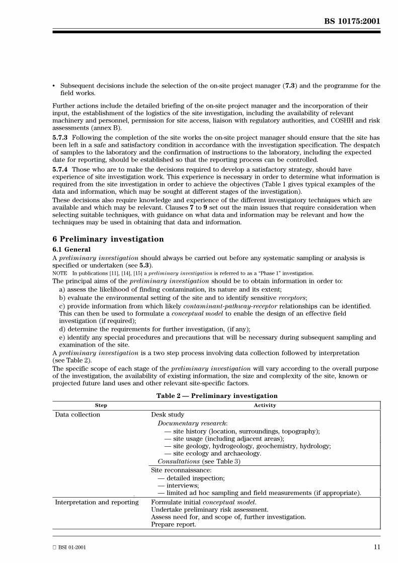
A preliminary investigation is a two step process involving data collection followed by interpretation(see Table 2).
The specific scope of each stage of the preliminary investigation will vary according to the overall purposeof the investigation, the availability of existing information, the size and complexity of the site, known orprojected future land uses and other relevant site-specific factors.
Table 2 Ð Preliminary investigation
Step Activity
Data collection Desk study
Documentary research:Ð site history (location, surroundings, topography);Ð site usage (including adjacent areas);Ð site geology, hydrogeology, geochemistry, hydrology;Ð site ecology and archaeology.
Consultations (see Table 3)
Site reconnaissance:Ð detailed inspection;Ð interviews;Ð limited ad hoc sampling and field measurements (if appropriate).
Interpretation and reporting Formulate initial conceptual model.Undertake preliminary risk assessment.Assess need for, and scope of, further investigation.Prepare report.
12 BSI 01-2001
BS 10175:2001
6.2 Data collection
6.2.1 Desk study
6.2.1.1 General
The desk study should comprise a combination of documentary research (see 6.2.1.2) and consultations(see 6.2.1.3).
The desk study should cover the following topics, where appropriate:
a) the history of the site and adjoining areas. Particular attention should be paid to the nature of anyindustrial processes or other activities on the site that could have been potentially contaminative or couldhave modified the ground structure to create potential migration pathways;
b) any previous desk study or investigation of the site;
c) the geological, geochemical, hydrogeological, hydrological, archaeological and ecological setting of thesite;
d) potential receptors of contamination (for example, current and intended users, trespassers, surfacewaters, groundwaters or nearby water abstractions, property);
e) the proximity of any licensed or unlicensed waste disposal sites or other sources of contamination,including hazardous gases, that could have an impact on the site;
f) the existence of naturally occurring harmful materials such as radon or naturally enhancedconcentrations of harmful substances;
g) the presence of any mining activities;
h) any constraints on an intrusive site investigation (access or height limitations, underground services orobstructions, noise, working hours, etc.).
6.2.1.2 Documentary research
6.2.1.2.1 Site location and historical setting
The level of historical research undertaken should be compatible with the objectives of the investigation.
The site location and site boundaries should be accurately established with the purchaser of thestudy (client) before commencing any investigatory work.
The site history should be determined using either the following or any other appropriate sources ofinformation:
Ð Ordnance Survey maps;
Ð other published maps, for example, insurance, tithe, enclosure or parish maps;
Ð aerial photographs;
Ð documentary records held by the current (and former) owners of the land, trade directories, the localauthority and local libraries.
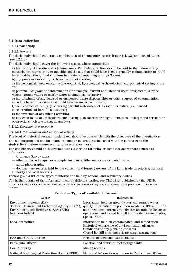
Table 3 gives a list of the types of information held by national and regulatory bodies.
For further details of the information held by different parties, see CLR 3 [16] published by the DETR.NOTE Over-reliance should not be made on past OS map editions since they may not represent a complete record of historicalland use.
Table 3 Ð Types of available information
Agency Information
Environment Agency (EA),Scottish Environment Protection Agency (SEPA),Environment and Heritage Service (EHS)Northern Ireland.
Information held on groundwater and surface waterquality; information on pollution incidents; IPC and IPPCauthorizations, current groundwater abstraction licences;operational and closed landfill and waste treatment sites,Special Sites.
Local authorities Information held on contaminated land remediation.Historical experience of environmental nuisances.Conditions of any planning consents.Closed landfill sites and private water abstractions.
HSE and Fire Authorities Records of accidents and incidents.
Petroleum Officer Location and status of fuel storage tanks.
Coal Authority Mining records.
National Radiological Protection Board (NPRB) Maps and information on radon in England and Wales.
BS 10175:2001
BSI 01-2001 13
1) More information can be obtained from British Geological Survey, Keyworth, Nottingham NG12 5GG. Tel 0115 936 3143.2) More information can be obtained from the local Environment Agency office.3) In Scotland, groundwater vulnerability maps can be obtained from BGS ± see footnote 1) above.
6.2.1.2.2 Site usage and contamination
Details of the past and current usage of the site, and its immediate environs including backgroundconcentrations, together with information on any incidents (such as spills or detected leakages) should becollated and used in the development of the initial conceptual model.
Land can become contaminated from a wide range of activities on the site, or on adjacent areas. Industrialsites (where contamination is likely) include, but are not limited to:
Ð landfill sites, other waste treatment, recycling and disposal operations and land surrounding these sites;
Ð sites of heavy industry;
Ð power stations or electricity substations and coal carbonization sites including gas works;
Ð chemical and manufacturing plants, particularly those involving hazardous processes, for example, usingor storing bulk liquid chemicals or discharging significant quantities of effluent;
Ð sewage farms and sewage treatment plants;
Ð breakers' yards;
Ð railway sidings;
Ð all works employing metal finishing processes (for example plating, paint spraying);
Ð fuel storage facilities, garages and petrol forecourts;
Ð former mining sites (particularly mines for metal ores);
Ð engineering works;
Ð works utilizing animal products, for example, tanneries;
Ð Ministry of Defence sites;
Ð timber treatment works.
The following information sources contain details of existing research into contamination issues associatedwith different industrial uses of land and should be consulted, where appropriate.
Ð CLR 3 published by the DETR [16];
Ð Industry Profiles, published by the DETR [17] (see Further reading on page 73 for a listing of theindustries covered);
Ð Guidance Notes published by the Interdepartmental Committee on the Redevelopment of ContaminatedLand [18];
Ð Appendix A of the Advice Note in Design Manual for Roads and Bridges [19].NOTE Handbook of model procedures [12], which is in the process of development by the DETR and Environment Agency, will alsobe a source document when published.
The documentary research should ascertain, if possible, whether any of the following occurrences (commoncauses of contamination) have taken place:
a) spills or leaks of noxious liquids from tanks, pipes and drains on the surface, or underground;
b) deposition or burial of industrial or domestic waste, or temporary stockpiling of leachable materials(for example, road salt);
c) demolition of industrial structures and dispersal or burial of contaminated rubble and other materials;
d) importation on to the land of contaminated fill material.
Table 3 gives details of the information held by national and local regulatory authorities. See also 6.2.1.3 forother information that should be discussed with regulatory authorities.
6.2.1.2.3 Geology, geochemistry, hydrology and hydrogeology
All readily available sources of information on the geological, geochemical, hydrological and hydrogeologicalconditions of the site should be collected and examined.
The following sources can be consulted:
Ð British Geological Survey (BGS) for geological, geochemical and hydrogeological maps1);
Ð Environment Agency for groundwater vulnerability maps2) 3) and information on source protectionzones; and
Ð the results of any previous ground investigations carried out on the site or information from nationalsurveys covering the vicinity.NOTE BS 5930 gives a comprehensive list of geological information sources. The supplement published in the Quarterly Journal ofEngineering Geology [20] also contains useful information1).
14 BSI 01-2001
BS 10175:2001
4) More information can be obtained from English Nature, Northminster House, Peterborough PE1 1UA. Tel 01733 455 000 or [email protected]; Scottish Natural Heritage, 12 Hope Terrace, Edinburgh EH9 2AS. Tel +44 (0)131 447 4784 or [email protected].; The Countryside Council for Wales, Plas Penrhos, Penrhos Road, Bangor, LL57 2LQ. Tel. 01248 385500Web site: www.ccw.gov.uk.5) More information can be obtained from MAFF, North Regional Service Centre, Edenbridge House, Carlisle CA3 8DX.
6.2.1.2.4 Ecology and archaeology
If a site (or its immediate environs) has been designated as an area of ecological or archaeologicalsignificance, it is likely that there will be constraints on the methods of ground investigation that can beused.
The following sources should be contacted to check if a site has a particular designation.
Ð English Nature/Scottish Natural Heritage/Countryside Council for Wales, for Sites of Special ScientificInterest4);
Ð Ministry of Agriculture, Fisheries and Food (MAFF) for Environmentally Sensitive Areas5);
Ð The local authority for any information included in their Development Plan. (These plans identify sitesof national and international importance as designated by English Heritage, Countryside Council of Walesand Scottish Natural Heritage, respectively, as well as sites of county and local importance.)
There may be species or habitats of importance or subject to legal protection under the Wildlife andCountryside Act or Habitat Regulations that are not in designated sites (for example nesting birds, watervoles).
6.2.1.3 Consultations
Consultation should be carried out with relevant parties, normally in parallel with the documentary research.
Interviews with persons holding knowledge of activities on, or adjacent to the site, may be combined withthe site reconnaissance visit. Such interviews provide the best opportunity to indicate suspect locations orfeatures, underground services, etc. but anecdotal evidence should be viewed with caution.
Consultations with the regulators should include discussion of acceptable methods of ground investigation. Itis vital that potential risks to groundwater, caused by the accidental creation of migration routes duringboring or trial pitting, are minimized. Client approval should be obtained before starting such consultations.
If investigations are likely to be undertaken on (or accessed via) ecologically sensitive sites or agriculturalland, English Nature, Countryside Council of Wales, Scottish Natural Heritage or local MAFF office should beconsulted to discuss acceptable methods of work.
6.2.2 Site reconnaissance
A reconnaissance of the site, neighbouring land and the local area should be made, where necessary andagreed with the client, ideally after carrying out documentary research (see also 6.2.1). Permission for accessto the site should be obtained from the owner and/or occupier as appropriate.
The purpose of the visit should be to:
a) validate information on the site collected during the desk study;
b) collect additional information about the site, its environs, and any potential contaminants, pathwaysand receptors;
c) record observations of aspects of the site not revealed by the desk study;
d) assist in the planning of any subsequent phases of field investigation (taking into account anyconstraints to access).
A strategy for the visit should be decided in advance and suitable plans, checklists and referencedocumentation prepared.
A COSHH assessment should also be carried out. This is particularly important on former industrial sites andwaste sites. In the case of the site reconnaissance, the hazard assessment should be based on the results ofthe desk study. It may be possible to refine the assessment once the preliminary investigation is completed.It should be kept under review as the investigation proceeds but where there is any doubt as to the presenceor degree of contamination then protective equipment should be used. Personnel undertaking the visit shouldbe thoroughly briefed on any hazards that could be encountered and on any precautions to be taken.
If operational buildings still exist, a review of the past and present usage of the property could be relevantand should be carried out, if required.
If possible, personnel should be accompanied by someone familiar with the site (such as a plant manager orsafety officer in the case of an industrial site). During the site visit photographs of salient features should betaken, where permissible.
BS 10175:2001
BSI 01-2001 15
A reconnaissance of the site may not always be necessary, for example where it is fully developed, anduseful information will not be derived. In some situations the client may not require site visits. In such casesthe agreed specification for the preliminary investigation should clearly state that a reconnaissance is notincluded in the work to be carried out.
Since a reconnaissance is part of the process of collecting information relating to the site, it is premature tocarry out systematic sampling at this stage; for example; any problems of access will not be appreciatedbefore the visit. However, testing for ground gases by driving a spike into the ground (spiking test) may alsobe carried out (see 7.6.4). Such testing should only be carried out if service plans are available and spikinglocations are checked with a cable avoidance tool. See 7.3 for further details.
Additional, detailed guidance on carrying out preliminary field inspections of potentially contaminated land isgiven in the following publications:
Ð CLR 2 published by DETR [21];
Ð SP103 published by CIRIA [11].
6.3 Interpretation and reporting
6.3.1 Formulation of initial conceptual model
Guidance on formulating an initial conceptual model is outside the scope of this standard.ASTM E1689-95 [43] gives guidance on formulating a conceptual model.
The information from the documentary research, site reconnaissance visit and consultations should becollated and evaluated to formulate an initial conceptual model of the site.
The initial conceptual model should identify, as far as possible:
Ð potential types and depths of contamination present in different zones of the site;
Ð the likely vertical and horizontal stratification of natural and manmade layers beneath the site;
Ð strata variability (occurrence and thickness) in different areas of the site, and their relativepermeability, both vertically and horizontally;
Ð potential migration routes (including airborne dispersion);
Ð the presence of services trenches, drainage runs, underground storage tanks, former foundations, andany other physical features that might influence the occurrence or migration of contamination. (Featureswhich might provide a constraint to investigation, such as power lines, should also be identified);
Ð the occurrence of any biological, chemical or physical processes that might affect contaminantconcentrations and migration (including natural attenuation);
Ð the characteristics of groundwater bodies beneath the site, groundwater levels and flow directions;
Ð the presence of surface water bodies on, or adjacent to the site;
Ð other potential receptors.
NOTE The initial conceptual model may also include hypotheses of the presence of made ground, underground obstructions, buriedriver channels, the expected directions of groundwater flow, number of aquifers and details of groundwater recharge, permeability of theground, the physical and chemical properties of the expected contaminants, their possible degradation products, the location and formof the contaminant source, duration, etc.
When further investigations are carried out the additional information should be used to refine theconceptual model.
6.3.2 Preliminary risk assessment
Guidance on carrying out a formal risk assessment is outside the scope of this standard. However, the riskassessment is likely to include the following aspects:
a) identification of contaminants, pathways and receptors;
b) estimation of the likelihood, nature and extent of exposure to a hazard; and the risk of adverse effects;
c) assessment of the likely pollutant linkages and the degree of risk;
d) evaluation of the need for controlling the estimated risk.
Where the existence of adequate site investigation information has been revealed by the preliminaryinvestigation, a quantitative, or semi-quantitative, risk assessment can be undertaken. Information fromprevious investigative works should be either verified or used with caution. However, where little or noprevious investigation has been undertaken, only a qualitative assessment can be made. The effects ofuncertainties in the information available on the outcome of a risk assessment should be identified.
NOTE The handbook of model procedures [12], which is in the process of development by the DETR and Environment Agency, willprovide guidance on risk assessment when published.
16 BSI 01-2001
BS 10175:2001
6.3.3 Further investigations
The findings of the preliminary investigation should form the basis upon which the requirement for, scopeof, and phasing of, subsequent investigations are decided.
The risk assessment and the objectives of the investigation should be reviewed and the need for furtherinvestigation considered.
This decision will depend upon the quantity and quality of previous site investigation information available,the level of confidence required from the actual characterization of ground conditions and hazards, and theresults of the risk assessment.
6.3.4 Reporting
The preliminary investigation should be completed by the issue of a report. Subject to the specific brief forthe investigation the report ideally should include the factual results of the desk study, site reconnaissanceand consultations, together with the conclusions drawn, (including presentation of the conceptual model),and recommendations on any further research and/or ground investigation to be carried out. The reportshould also describe the results of the preliminary risk assessment.NOTE For further guidance on reporting, see clause 10.
7 Design and planning of field investigations
7.1 General
The field investigation should be designed in accordance with the objectives (see clause 4 and Table 1) toprovide further information to enable revision and updating of the conceptual model and the risk assessment.Strategy for field investigations is discussed in clause 5 where three types of field investigations areidentified:
Ð exploratory (see 5.4 and 5.7);
Ð main (see 5.5 and 5.7);
Ð supplementary (see 5.6 and 5.7).
For each of these investigations the conceptual model is at a different stage of development and there can bea need for different information with different degrees of confidence. For example, in the exploratoryinvestigation information confirming the presence of a potential contaminant may be required, whilst in themain investigation the same area needs to be much more accurately defined and migration pathwaysconfirmed. In the supplementary investigation the delineation of migration pathways needs to bedetermined to a degree of accuracy to enable costing for remedial work to be calculated.
Typical field investigations should be designed to:
Ð determine (with a degree of confidence appropriate to the objectives) the presence, concentration anddistribution of contaminants on the basis of the conceptual model and the information currently available;
Ð consider ground and groundwater conditions including hydraulic gradient, soil permeability, porosity,density, moisture, particle size, etc., as these can influence contamination movement;
Ð characterize any potential pathways in terms of migration and possible attenuation;
Ð where known contamination exists, collect additional data for the delineation and design of remediationplans.
The investigation should be designed to confirm the extent of contamination in areas where it is suspected,and to confirm the absence of contamination in the rest of the site. The analytical suite should includetesting for both commonly occurring contaminants and for those linked to the historical activities on thesite.
If it is necessary to demonstrate that a site is uncontaminated, a detailed investigation covering the entiresite should be carried out. The intensity of the investigation will depend on the degree of confidencerequired in assessing whether there is an absence of contamination.
Migration of contamination off-site, or on to a subsequently remediated site, is an important consideration. Insituations where there are potentially sensitive receptors or sources of contamination located outside thesite, the fieldwork should include investigation at, or beyond, the site boundary. In practice, however, off-siteaccess can be restricted due to land ownership. Permission for access to such adjacent areas should beobtained.
Where relevant, site investigation proposals should be discussed with the Environment Agency and the localauthority for the area (in order to incorporate any specific measures and gain confidence that the outcomeof the investigation will satisfy regulatory requirements) can be necessary (see 6.2.1.5).
The permission of the site owner should be obtained, preferably in writing, prior to the commencement ofthe site investigation.
BS 10175:2001
BSI 01-2001 17
7.2 Integrated investigations
Integrated investigations that meet the needs of both contamination and geotechnical aspects can offerbenefits. Integrated investigations have the following advantages:
Ð simplified project management;
Ð common use of equipment and procedures;
Ð exploratory holes can be used for more than one purpose;
Ð joint health and safety procedures can be established;
Ð joint environmental protection procedures can be established;
Ð integrated consideration of resultant data.
Linking the work with other types of studies can also be appropriate in some circumstances. In particular,the ecological survey of a site and surrounding area may indicate contamination on the basis of observedimpacts on flora. Archaeological and contamination investigations can share information from geophysicalsurvey work (see 8.2.2).
The degree of integration should be based upon the findings of the preliminary investigation. Anyintegrated investigation, using multi-disciplinary teams, however, should be designed so that it does notcompromise the requirements of either investigation. For example, sampling locations for contaminationshould not be moved from a selected grid pattern (see 7.6.2) in order to accommodate geotechnicalrequirements.
7.3 Personnel and environmental protection
Guidance on site safety issues that should be addressed in any investigation is provided in annex B, to whichreference should be made.
It is important that personnel, in particular the team leader(s), have an adequate understanding of thetechnical issues involved. See also 7.8. This requires knowledge and experience of investigation and samplingtechniques, and an appreciation of the characteristics of the materials likely to be encountered. Personnelshould have a working knowledge of the health, safety and environmental issues involved. The followingpublications give additional guidance.
Ð CLR12 published by DETR [22];
Ð Good practice in site investigations, published by the Association of Geotechnical andGeoenvironmental Specialists [23];
Ð HS(G)66 published by HSE [24];
Ð Guide R132 published by CIRIA [25];
Ð ISO/DIS 10381-3;
Ð Guidelines for the safe investigation by drilling of landfills and contaminated land, published by the SiteInvestigation Steering Group [45].
It is essential that investigations avoid creating a nuisance to neighbouring residents or occupants, orcreating a hazard to the environment.
Any services should be located and identified by reference to the utility companies or to service plans forprivate land and by using services detection equipment, to prevent accidental damage. The area of samplinglocations should also be visually inspected for possible services prior to commencement of an intrusiveinvestigation.
7.4 Pre-investigation considerations
7.4.1 Demolition and clearance
Where buildings exist, but are to be removed as part of a redevelopment, it is sometimes necessary to carryout the field investigation in two stages. Accessible sample locations can be investigated initially and theremainder can be accessed after demolition has occurred. If buildings are dilapidated, great care should betaken to prevent the site investigators being exposed to risks posed by the buildings, for example, asbestosfibres or falling masonry.
When demolition is carried out, attention is drawn to statutory requirements for CDM designer riskassessments and Health and Safety plans [9]. Prior to demolition a specialist survey should be undertaken todetermine the nature and extent of the hazards present. This can sometimes necessitate sampling and testingto establish the contents of vessels and pipework, the presence of contaminated building fabric or thepresence of asbestos.
All demolition should be undertaken in accordance with BS 6187.
18 BSI 01-2001
BS 10175:2001
Some buildings require special procedures to be followed before the site is cleared, for example, if hazardsfrom asbestos, radioactive substances or biological organisms are present. Where the site history shows thatsuch hazards are likely to be present, the engagement of specialist decontamination or demolitioncontractors is essential.
Care should be taken to avoid spreading contamination during site clearance work as indiscriminatedemolition can lead to greatly increased decontamination costs.
Further guidance can be obtained from SP 102 published by CIRIA [46].
7.4.2 Disposal of rubble and waste materials
Tanks and pipes (both above and below ground) and cavities can contain significant amounts of hazardoussubstances long after an industrial site has closed. Damage to tanks, pipes and drains or the relocation ofmaterials within the site can result in the spread of contamination.
If any residues or raw materials are present, especially in liquid form, consideration should be given to thenature of the material and the need for removal before site clearance or sampling begins. This cannecessitate a separate preliminary sampling exercise prior to removal.
Intrusive investigations themselves can often lead to the generation of waste material including spoil andgroundwater. Suitable disposal routes should be identified and arranged before the work begins. However,analytical data are likely to be necessary before a suitable disposal route can be confirmed. In theintervening period the material should be made secure.NOTE 1 The investigatory team is responsible for the safe disposal of ªarisingsº both solid and liquid to a suitably licensed locationunder the Environmental Protection (Duty of Care) Regulations 1991 [26].
NOTE 2 Certain materials are designated ªSpecial Wasteº and the appropriate environment agency requires notification prior todisposal. Attention is drawn to the Special Waste (Amendment) Regulations 1996, [27].
7.5 Method of field investigation
7.5.1 General
The strategy of the field investigation (see clause 5) should be formulated to suit the objectives and sitespecific features. Investigation of a site can be carried out by non-intrusive and/or intrusive methods.
7.5.2 Non-intrusive
Non-intrusive investigations can be carried out using a range of technologies; the advantages anddisadvantages of which are discussed in 8.2.2 and Table 5.
These methods can be useful within a preliminary investigation or as part of an exploratory investigationwhere the presence, but not the specific locations, of features associated with contamination is suspected.
The feasibility of using non-intrusive techniques can be dependent on ground conditions and the features ofinterest, and should be selected for a particular site by discussion with specialists in relevant methodologies.
7.5.3 Intrusive
The objectives of most field investigations will result in a need to collect samples of soil, water, and soil gasand there are different technologies available for such sampling. The technologies selected will be chosenhaving regard to the samples to be collected, the locations and depths of sampling and the constraints of thesite (e.g. limited access, hard landscape).
The methods of carrying out intrusive investigations, including the installation of permanent andsemi-permanent monitoring wells, are discussed in 8.2.3 and Tables 6 and 7, where the advantages anddisadvantages are described.
Where groundwater or soil gas contamination is suspected, monitoring wells that allow specific samplingrequirements to be met should be installed. Water samples obtained during trial pitting and drilling may bescreened for the presence of groundwater contamination and to establish the need to install monitoringwells. However, caution should be applied when considering the analytical data from such samples, since theground disturbance caused by the drilling or digging can affect the composition of the water sample.
It is essential that the need to prevent contamination migration (caused by the creation of temporary orpermanent connection between aquifers or between contaminated ground and underlying aquifers) isconsidered when selecting an investigation technique (see 8.2.3.1).
In many cases it is advisable to discuss investigation proposals with the appropriate environment agency inorder to incorporate their particular requirements.
In order to select appropriate sampling techniques for investigation, the requirements for sampling need tobe established and the remainder of clause 7 provides guidance on determining where, what type and atwhat depth samples should be collected and monitoring facilities installed. Sub-clause 8.3 provides details,plus indications of the advantages and disadvantages, of the various sampling techniques that are availablefor carrying out an intrusive investigation.
BS 10175:2001
BSI 01-2001 19
7.6 Sampling strategies
7.6.1 General
The sampling strategy for any phase of intrusive investigatory fieldwork that follows the preliminaryinvestigation should identify the following:
a) the objectives of the investigation and the possibility of zoning the site (see 5.3);
b) the location, pattern and number of sampling points (see 7.6.2.1 to 7.6.2.4);
c) the depths from which samples should be collected, the samples to be collected and any monitoringrequirements (see 7.6.2.5);
d) the analyses required and whether any in-situ or on-site testing is appropriate and necessary (see 8.4.2and 9.1);
e) the methodology by which samples should be collected (clause 8), stored and preserved (8.6), takinginto account any off-site analysis to be undertaken (see clause 9);
f) any safety measures needed to protect personnel or the environment (see 7.3 and annex B).
Additional site-specific factors, (for example, the site size and topography, depth of groundwater and itsdirection of flow or any physical obstructions) should be identified.
The sampling strategy should allow flexibility so that representative samples of all strata and materialsencountered, are collected, including any anomalous material.
The investigation design should address the needs of the risk assessment. For example, the number ofsamples for site characterization or statistical analysis should be sufficient for the chosen methodology. Thereason(s) for choosing a sampling strategy (including the choice of locations and frequency of sampling)should be included in the final report (see 10.3).
Potential heterogeneity of distribution of contaminants should be taken into account when designing thesampling strategy, particularly in relation to the risk assessment and the degree of confidence required, sincethis will have an impact on the sample locations selected and the number of samples collected (see 7.6.2).
It is important that any sample submitted to the laboratory is representative of the location and depth fromwhich the sample was taken (see annex D for the collection of a representative soil sample). Greaterconfidence in the site assessment can be achieved by increasing the number of samples taken and analysed,as significant differences in the sample composition over small areas within the site can occur. The errorsassociated with sampling in site investigations are generally greater than those associated with the analysis.It can therefore be more informative to analyse a greater number of samples using methodology fit for thepurpose, than to analyse a smaller number of samples using a more accurate method.
Water bodies tend to be more homogeneous in composition than soil. A water sample can represent a fargreater volume of water than can a corresponding sample volume of soil. However, stratification can stilloccur in groundwater and surface waters. This should be taken into account in the design of the samplingstrategy. Allowance should also be made for contamination migrating against the direction of water flow, forexample, where the direction of movement of dense non-aqueous phase liquids permeating into the ground isaffected by impermeable material such as obstructions or clay (see also 7.6.3.5).
Soil gas samples are similar to water samples in that they can be representative of a large zone.Nevertheless, the sampling strategy differs from that used for waters because of the greater ability of soilgases to migrate in all directions within the ground. Where monitoring locations for groundwater and soilgases are coincident, it is not always possible to install a joint monitoring well.
The sampling strategy should take into consideration the possibility of creating routes for migration(see 7.6.3.6).
Where near surface samples are not required and samples are required only at greater depth within theground, an appropriate method of rapid development of the borehole to the required depth may be used.Care should be taken, however, to protect the bore and to clean out material before taking a sample, toavoid cross-contamination (see 8.2.3.3).
Equipment should be cleaned between use at different sampling locations and within locations when formingboreholes, to prevent cross-contamination of samples (see 8.2.3.3).
Sampling locations should be surveyed in accurately, in both plan and elevation, from permanent markswhich should preferably be related to Ordnance Survey Grid and Datum. The use of Global PositioningSystems (GPS) should not preclude the inclusion of permanent marks.
20 BSI 01-2001
BS 10175:2001
7.6.2 Sampling of soils
7.6.2.1 Sampling locations
There are two principal approaches to the sampling of soils:
a) targeted or judgmental sampling, which focuses on known, suspected, or point source areas ofcontamination (see 7.6.2.2);
b) non-targeted sampling, which aims to characterize the contamination status of a defined area or volumeof a site, or zone (see 7.6.2.3).
Where a conceptual model divides the site into zones with potentially different contamination characteristics,the balance between the two approaches may be different in the different zones.
Exploratory investigations can place greater emphasis on the confirmation of suspected sources ofcontamination, (for example, storage tanks or below-ground pipelines) by targeted sampling, with limitednon-targeted sampling to allow consideration of general areas of the site. Main investigations should use acombination of the two approaches probably with greater emphasis on non-targeted sampling.
The distribution of contaminants on a site can vary because the contaminants have different origins. Even iffrom the same source, they can behave differently in the ground. It is normally relatively cheap to collectsamples during the course of a site investigation even if it is not intended to immediately analyse them all. Ifsamples are properly preserved and stored, the additional costs of a further sampling exercise can beavoided. It can be considered beneficial to collect more samples than will be analysed. Deficiencies in thedata, identified after completion of the testing, can then be more readily remedied by analysis of storedsamples.
The number and frequency of sampling locations should take into account the risk assessment and thedegree of confidence required that hazards have been identified. The more sensitive the receptors or thegreater the hazard, the greater the degree of confidence needed in the outcome of the risk assessment andthe subsequent risk management. In such cases, a greater number of sampling locations and samples will beneeded. Other factors, such as accurate delineation of an area of contamination, also necessitate moreintensive sampling.
NOTE The handbook of model procedures [12], which is in the process of development by the DETR and Environment Agency, willprovide guidance on risk assessment.
7.6.2.2 Targeted (judgmental) sampling
Targeted (judgmental) sampling involves sampling at locations, that are selected on the basis of theconceptual model, and that are known, or suspected to be, sources or areas of contamination. The locationsmay also be positioned along probable migration routes of mobile contaminants.
Potential point sources of contamination include past or present storage tanks (above and below ground),below ground fuel supply pipework, drains, backfilled pits and waste disposal areas, handling areas wherespills of hazardous materials could have occurred, etc.
The number of sampling locations should depend upon the potential source of contamination and its nature.A low number of locations (for example, one to four), with sampling at different depths as determinednecessary to detect the contamination, can be sufficient within an exploratory investigation.
In a main investigation a greater number of sampling locations can be required, for example, wheredelineation of an area of contamination is required. In this situation, the location of the sampling points andthe distance between each sampling location and the ªcentreº of the targeted contamination, will beinfluenced by the conceptual model and the realistic likely spread of the contamination. Sampling points maybe located at equal spacing and increasing distance from the ªcentreº having regard to the possible migrationof the contamination. Different juxtapositions of sampling locations will be required when delineating a pointsource, a plume of, or linear, contamination. Delineation may be achieved by extending the sample locationsso that at least two locations in any direction do not give concentrations of the targeted contaminant greaterthan the threshold guidance value being applied to the site.
Installation of facilities for monitoring groundwater (7.6.3) or soil gas (7.6.4) may be targeted ornon-targeted depending on the information available and the information sought. If convenient, such targetedmonitoring locations may be installed as part of a regular sampling pattern. However, monitoring locationsshould not be placed within a regular sampling pattern if this could compromise the quality of data. Whereuse of locations on a regular sampling pattern is possible, soil samples for subsequent analysis can beobtained during the installation of monitoring wells. These soil samples can form part of the non-targetedinvestigation for soil contamination.
BS 10175:2001
BSI 01-2001 21
7.6.2.3 Non-targeted sampling
Non-targeted sampling should usually be carried out using a regular pattern of sample locations.
The reasons for selecting a regular sampling pattern in site investigations are:
Ð the reliability of interpolation between sampling locations declines sharply as distance increases.Additional samples can be taken at a later stage within the pattern to reduce the distance betweenlocations (see 7.6.2.4);
Ð data from different stages of investigation can be readily correlated;
Ð sampling locations are simpler to establish in the field;
Ð location of areas of contamination is simplified;
Ð design of further investigations is easier.
Reliability of interpolation between sample locations depends on variations in soil characteristics. Forexample, in well-stratified sediments, vertical variations in concentration will normally be much greater thanhorizontal variations so that interpolation horizontally will be much more reliable than vertical interpolation.Vertical interpolation through different strata is not possible.
If there are any regular topographical patterns on the site (ditches at regular intervals, systematicundulations of the terrain, etc.), the sampling pattern should not coincide with the topography in a way thatcould introduce a bias or systematic error in the samples. This can be avoided by careful selection of thebase or starting point of the sampling grid and, where necessary, by careful selection of the grid spacing.
7.6.2.4 Non-targeted sampling patterns
A simple, regular sampling pattern allows selection of locations for different stages of investigation. Thisstandard does not give detailed guidance on sampling patterns but various patterns of sampling have beenidentified (see CLR 4 [28] and SP103 [11] for further information).
a) The most common pattern used for establishing sample locations is the square grid with samples takenat the intersections. A square grid sampling pattern has the advantage that a wide spacing can be used inan exploratory investigation. Additional sample locations can be readily located within that pattern insubsequent investigations by reducing the grid spacing. This is particularly useful as an aid tointerpretation by interpolation and also when designing any further investigation.
b) The herringbone pattern, which uses a form of offset regular grid, is statistically more likely to identifylinear contamination in two dimensions, see CLR 4 [28].
However, when choosing the sampling pattern, it should be borne in mind that contamination with sharplydefined boundaries rarely exists. Increasing concentrations can be used as broad indicators of a greaterdegree of contamination even though the areas of highest concentration may not have been sampled.
NOTE Studies, (for example, CLR 4 [28]) that have been undertaken to evaluate the relative efficiencies of various non-targetedsampling patterns for different shaped hot spots have indicated that both square and herringbone grid patterns give adequate results.
7.6.2.5 Sampling density
The spacing between sampling locations should be determined according to the conceptual model, the stageof the investigation, and the requirements of the risk assessment. An exploratory investigation usuallyrequires a lower density sample spacing than does a main investigation. In both investigation types,however, the actual density should depend upon the confidence and robustness required of decisions thatwill be based on the information obtained. Thus the area and depth of interest will be related to thecontaminants present, the pathways and the receptors, and the smallest area that might be of concern(in the case of domestic housing with gardens, this could be the size of a garden).
Typical densities of sampling grids can vary from 50 m to 100 m centres for exploratory investigations,and 20 m to 25 m centres for main investigations. A greater density of sampling grid could be consideredappropriate where heterogeneous contamination is indicated, for example, on a former gasworks site wherein localized areas, 10 m centres may be necessary. A high density sampling grid can also be necessary wherea high level of confidence is required for the outcome of a risk assessment (for example, for a housingdevelopment).
NOTE The handbook of model procedures [12], which is in the process of development by the DETR and Environment Agency, willalso be a source of guidance on risk assessment when published.
Lower density sample locations may be acceptable on large sites, subject to the chosen spacing providingadequate data and being consistent with the objectives of the investigation.
22 BSI 01-2001
BS 10175:2001
6) Available from British Geological Survey, Keyworth, Nottingham NG12 5GG. Tel 0115 936 3143 and also from Soil Survey and LandResearch Centre, Cranfield University, Silsoe, Bedford MK45 4DT.7) Available from Imperial College, Dept. of Geology, Prince Consort Rd, London SW7 Tel: 0207 594 6538.
7.6.2.6 Composite sampling
Composite sampling is not recommended for the investigation of potentially contaminated land due to thefollowing drawbacks:
Ð the difficulty of comparing resultant data with guideline concentrations that relate to spot samples;
Ð the possibility of disguising isolated locations of high concentration by mixing with samples of lowerconcentration;
Ð the possibility of loss of volatile compounds during the compositing processes;
Ð the difficulty of achieving an adequately mixed and representative sample.NOTE Composite sampling consists of collecting a number of equally spaced samples of the same size, following a prescribed pattern,over a field or part of a field. These samples are bulked together to form the composite sample. This sample represents the mean qualityof the area sampled. Composite sampling is often used where a sample is required to evaluate soil quality for agricultural purposes.Where used, it should only be carried out for a single specific stratum.
For advice on the collection of soil samples see 8.3.2.
7.6.2.7 Sampling depths
When developing the sampling strategy, the sampling depths should be considered after establishing thesampling locations.
A soil sampling strategy is likely to include taking the following:
a) samples from the immediate surface layer. This layer should be defined on a site-specific basis relatedto the conceptual model and the risk assessment. The surface layer sampled may vary between the surfaceand a depth of 0.5 m and may require sampling at more than one depth. Material that could either bedisturbed by rainwater runoff and carried to adjacent water bodies, or present an immediate exposurehazard, can require sampling in the uppermost 0.1 m. Where there are health hazard concerns, for example,in domestic gardens, samples should be taken at 0.1 m and 0.5 m. However, sampling at intermediatedepths may also be appropriate;
b) samples from within made ground or fill strata at fixed depth intervals, (often 0.5 m);
c) provision for collecting samples within made ground or fill to reflect any identifiable changes inappearance, in strata or in material (i.e. ªmaterial of interestº);
d) samples of natural ground beneath made ground or fill. The first of these should be close to theboundary with the made ground or fill (approximately 0.25 m to 0.5 m into natural ground).
If the conceptual model or on-site investigations indicate the need to continue sampling into the naturalground underlying the site, for example, in more permeable ground, sampling should be carried out asdeep as is necessary to characterize and identify contamination migration. Samples are typically collectedat 1.0 m depth intervals in natural ground, but this will depend upon the conceptual model, therequirements of the risk assessment and on-site observations.
Sampling of ground in the capillary zone immediately above the water table should be considered, as slightlysoluble compounds tend to concentrate in this region.
NOTE Where there is likely to be removal of ground for engineering purposes, this should be taken into account, when determining thesampling depth. This allows adequate information on the contamination status at the anticipated reduced level to be obtained.
The depths of sampling should take into account the nature of the proposed development. For example,services and strip foundations are typically installed to a depth of 1.5 m but main sewers can be installed atmuch greater depths.
The samples should be collected to represent a specific depth or narrow band of strata. Samples, which aretaken over a greater depth of strata, (for example 0.5 m), can be less satisfactory.
Samples of natural strata, if uncontaminated, can indicate the local, natural (background) chemicalconditions and can be of assistance when determining the extent of contamination migration and/or thedegree of remediation that is appropriate. Soils taken from beneath made ground can be subsoils and candiffer in composition from the topsoils that would be naturally associated with them. Data on typical topsoilconcentrations in rural and urban areas are available in the following publications:
Ð Recycling derelict land, Fleming. 1992 [29];
Ð Soil geochemical surveys6);
Ð geochemical atlases7).
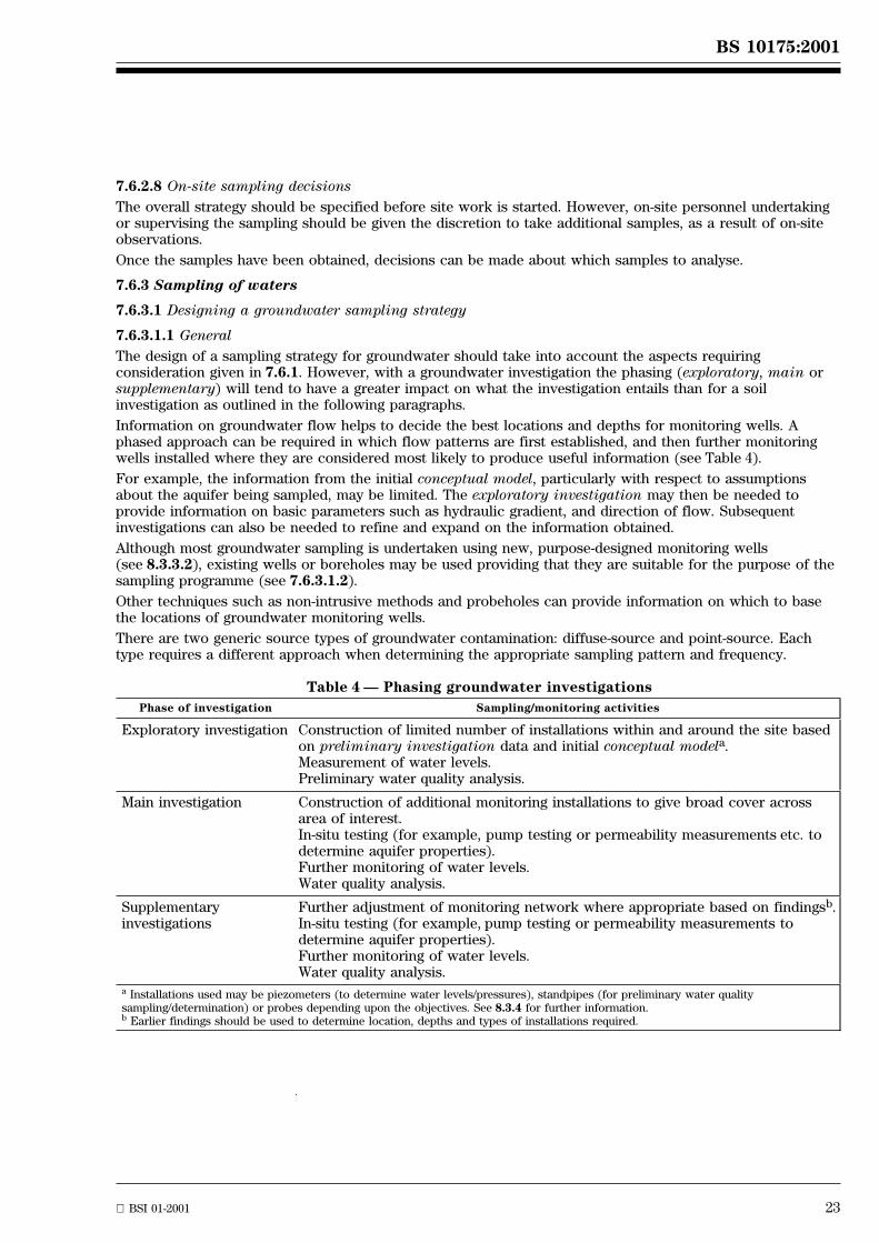
BS 10175:2001
BSI 01-2001 23
7.6.2.8 On-site sampling decisions
The overall strategy should be specified before site work is started. However, on-site personnel undertakingor supervising the sampling should be given the discretion to take additional samples, as a result of on-siteobservations.
Once the samples have been obtained, decisions can be made about which samples to analyse.
7.6.3 Sampling of waters
7.6.3.1 Designing a groundwater sampling strategy
7.6.3.1.1 General
The design of a sampling strategy for groundwater should take into account the aspects requiringconsideration given in 7.6.1. However, with a groundwater investigation the phasing (exploratory, main orsupplementary) will tend to have a greater impact on what the investigation entails than for a soilinvestigation as outlined in the following paragraphs.
Information on groundwater flow helps to decide the best locations and depths for monitoring wells. Aphased approach can be required in which flow patterns are first established, and then further monitoringwells installed where they are considered most likely to produce useful information (see Table 4).
For example, the information from the initial conceptual model, particularly with respect to assumptionsabout the aquifer being sampled, may be limited. The exploratory investigation may then be needed toprovide information on basic parameters such as hydraulic gradient, and direction of flow. Subsequentinvestigations can also be needed to refine and expand on the information obtained.
Although most groundwater sampling is undertaken using new, purpose-designed monitoring wells(see 8.3.3.2), existing wells or boreholes may be used providing that they are suitable for the purpose of thesampling programme (see 7.6.3.1.2).
Other techniques such as non-intrusive methods and probeholes can provide information on which to basethe locations of groundwater monitoring wells.
There are two generic source types of groundwater contamination: diffuse-source and point-source. Eachtype requires a different approach when determining the appropriate sampling pattern and frequency.
Table 4 Ð Phasing groundwater investigations
Phase of investigation Sampling/monitoring activities
Exploratory investigation Construction of limited number of installations within and around the site basedon preliminary investigation data and initial conceptual modela.Measurement of water levels.Preliminary water quality analysis.
Main investigation Construction of additional monitoring installations to give broad cover acrossarea of interest.In-situ testing (for example, pump testing or permeability measurements etc. todetermine aquifer properties).Further monitoring of water levels.Water quality analysis.
Supplementaryinvestigations
Further adjustment of monitoring network where appropriate based on findingsb.In-situ testing (for example, pump testing or permeability measurements todetermine aquifer properties).Further monitoring of water levels.Water quality analysis.
a Installations used may be piezometers (to determine water levels/pressures), standpipes (for preliminary water qualitysampling/determination) or probes depending upon the objectives. See 8.3.4 for further information.b Earlier findings should be used to determine location, depths and types of installations required.

24 BSI 01-2001
BS 10175:2001
7.6.3.1.2 Sampling strategy for diffuse-source contamination of groundwater
Diffuse source contamination of groundwater can be the result of a number of diffuse inputs from within asite but can also result from off-site sources. When there is no clearly defined source, groundwatermonitoring wells should be installed on a non-targeted basis (see 7.6.2.3 and 7.6.2.4).
The monitoring wells should be used to determine the direction of groundwater flow, and the water qualityupon entering and leaving the site. On a small site this will probably require at least four monitoringlocations. Wells should be located on the site so that they can be triangulated. Wells in a line will notprovide adequate information to establish the direction of groundwater flow.
In some circumstances it is possible to obtain data in relation to, or collect samples from, existingabstraction wells. Such wells are usually screened across the aquifer and hence samples will only reflect theintegrated water quality and can result in dilution of contamination below the limit of detection.
For further guidance on the design of the sampling strategy for diffuse contamination see BS 6068-6.11.
NOTE Further guidance can be obtained from the following documents:
ISO/DIS 5667-18;
Marsland and Carey [39];
Environment Agency Ð Guidance on monitoring of landfill leachate, groundwater and surface water Ð currently at Draft forConsultation status [40].
7.6.3.1.3 Sampling strategy for point-source contamination of groundwater
Monitoring well locations should be determined on the basis of the information available and the need forfurther information about the source and the migration of contaminants. The monitoring wells will thereforebe located on a targeted basis (see 7.6.2.2). Subsequent monitoring wells can then be located on the basis ofthe information from the initial installations and therefore again will be installed on a targeted basis.
Wherever practicable, a groundwater monitoring well should be installed directly below the potential source.However, such installations can allow contaminants to migrate vertically. An alternative position (thatreduces the possibility of vertical migration but doesn't identify the maximum concentration ofcontamination) is to install the monitoring well at the outer down-gradient edge of the potential source.
A groundwater monitoring well should be installed up-gradient of the potential source and a minimum of twoshould be installed down-gradient of the potential source. These monitoring wells can also be used todetermine the direction of groundwater flow and the quality of the groundwater flowing onto the site.
Further monitoring wells should be considered (depending upon the objectives and phase of theinvestigation), for example, at progressive distances down the hydraulic gradient from the source ofcontamination. Provision should also be made for sampling from a range of depths (see BS 6068-6.11 forfurther guidance.)
NOTE ISO/DIS 5667-18 also gives guidance.
7.6.3.2 Tools for assisting strategy design
A number of tools can be used in the design of the groundwater sampling strategy. These design toolsinclude:
a) flow net modelling: if data from several groundwater monitoring locations are already available, it ispossible to move beyond a groundwater contour plan and establish the most likely flow paths ofgroundwater from various areas under a site, by constructing a groundwater equipotential plan;
b) mathematical modelling: the use of appropriate computer modelling packages can be considered duringmost stages of groundwater investigations as these help to analyse and portray data, and hypotheses onthe rate and direction of contaminant movement can be derived.
7.6.3.3 Nature of contaminant (including non-aqueous phase liquids)
In designing a groundwater monitoring programme, consideration should be given to the nature of the likelycontaminants. If contaminants are encountered which were not anticipated, this may lead to asupplementary investigation to allow the installation of specific monitoring wells to address thecontamination encountered.
Groundwater monitoring will include addressing contaminants in solution such as metals, organiccompounds (for example phenols) and also the possibility of hydrophobic materials (for examplenon-aqueous phase liquids ± NAPLs) which may be present as free product.
Where volatile NAPLs are likely to be present, information on the potential location of contamination andmigration plume can be obtained by carrying out soil gas monitoring (see 7.6.4.3). This information can beused for determining the location of monitoring wells.
BS 10175:2001
BSI 01-2001 25
If NAPLs are present, consideration should be given to the effect of the following factors on theirdistribution in the groundwater:
Ð solubility (both in water and solvents);
Ð sorption;
Ð degradation and metabolites;
Ð potential for migration.
Where liquids that are less dense than water (light non-aqueous phase liquids ± LNAPLs) are present, at leastone borehole should be screened over a depth range that spans the level of the water table so that they canbe more easily detected and the thickness of the LNAPL layer measured.
Dense non-aqueous phase liquids (DNAPLs) will move to the base of the hydrological unit and can collecton, or be deflected by, lenses of low permeability material. Investigations for DNAPLs are difficult andrequire monitoring wells that fully penetrate the aquifer and are screened at the base and at points wherelow permeability material is present. Separate wells, formed to different depths can be necessary atmonitoring locations due to the difficulty of forming adequate seals in nested wells.
NOTE Further guidance can be obtained from Marsland and Carey [39] and the Environment Agency [40].
7.6.3.4 Low permeability strata
Where a monitoring well installation passes through low permeability strata, routes allowing dispersal ofcontamination into underlying groundwater can be created. In such situations, a larger diameter hole shouldbe formed down to the low permeability strata and an impermeable plug of bentonite/cement grout, with aminimum thickness of 1.0 m, inserted. Contamination can adversely affect the plug and, if necessary, suitablealternative material should be selected. This may necessitate some preliminary trials to confirm that theselected material is effective. The plug should be allowed to set before continuing the borehole by forming asmaller diameter hole. In this way a seal (to prevent the downward migration of contamination) is created.See also 8.2.3.1. The borehole should be grouted as the casing is withdrawn in order to complete the seal.
Using a phased approach to investigation (as well as appropriate installation techniques), particularly wheresevere contamination is suspected, can alleviate the problem of migration contamination.
When all monitoring work has been completed and there is no further need for the monitoring wells, theseshould be sealed by grouting with suitable material, ensuring that the grouting is effective above and belowthe water table.
7.6.3.5 Monitoring timing and frequency
Further guidance on sampling frequency is given in BS 6068-6.11.
NOTE 1 ISO/DIS 5667-18 also gives guidance.
Where practicable, groundwater should be characterized using data from repeated sampling operations.
It is not possible to provide guidance for a sampling programme that covers all eventualities. However,consideration should be given to taking two or three sets of samples over a short period of time (perhapsseparated by a few weeks) and then to progressively extend the period between sampling (typically everythree months), depending upon the findings.
NOTE 2 This general approach can be adapted to take into consideration known or expected fluctuations in groundwater levels, flowdirections, etc.
NOTE 3 For objectives other than potable supply surveillance, the sampling frequency should be chosen according to the temporal andspatial variations in groundwater quality. Changes in the quality of groundwater are usually much more gradual in time and space thanthose in surface waters. In some aquifers, factors producing seasonal variations in quality exist.
NOTE 4 Continuous monitoring of pH, temperature and electrical conductivity can provide a useful means of monitoring the need toincrease or decrease the sampling frequency. In cases where there has been a considerable change in any of the parameters, it isadvisable to consider extending the range of parameters monitored.
7.6.3.6 Sampling of surface waters
Collection of surface water samples and sediments from surface water should be carried out in accordancewith the guidance in BS 6068, 6.4, 6.6 and 6.12.
When sampling surface water on a contaminated site, care should be taken to safeguard theinvestigator/sampler because of the possibility of water being sufficiently contaminated to cause harm.

26 BSI 01-2001
BS 10175:2001
7.6.4 Sampling of soil gas
7.6.4.1 General
Where there is the possibility of soil gas contamination (for example, on or adjacent to areas of landfill,alluvial ground, solvent or fuel storage, mining, buried dock sediment and/or peat) it is necessary todetermine the composition and migration potential of the soil gas. Degradation of organic matter can giverise to both methane and carbon dioxide, and to a variety of trace gases, depending on the groundconditions and the nature of the material. Gases can also be transported in solution by migrating landfillleachate and groundwater.
Volatile organic compounds (VOCs) can have associated vapours, the concentrations of which can vary inthe soil gas above different parts of a plume but which can be used to indicate the location of the plume.
Different methodologies, dependent on the nature of the contamination, are used in soil gas investigations,but the sampling strategy should take into account the aspects set out in 7.6.1.
When interpreting data from driven tube sampler holes, cable percussion boreholes and monitoring wells, thestrata penetrated should be taken into account, as smearing during the formation of the borehole for theinstallation can reduce the porosity of the ground and affect gas migration.
NOTE Special safety considerations, which relate to the potentially significant risks of toxic effects, asphyxiation or explosion, arenecessary whilst investigating and monitoring suspected or known sources of gas emission. If a site poses a potential gas hazard, aªpermit to workº system should be instigated. This involves screening the area for harmful gases at ground level.
7.6.4.2 Soil gas from decomposition of organic matter
7.6.4.2.1 Sampling strategy
Investigations for gases, which derive from the decomposition of organic matter, generally use monitoringwells to enable on-site monitoring with portable instruments and the collection of samples for laboratoryanalysis (see 8.3.4).
Monitoring well locations should be determined on the basis of the available information and conceptualmodel, and the additional information required to fulfil the objectives. Monitoring well locations may betargeted (for example where a particular area of a site is suspected of forming landfill gases), ornon-targeted (for example where a site is underlain by alluvium). Subsequent monitoring wells may then bepositioned on the basis of the information obtained from the initial installations.
The location of gas monitoring wells should take into consideration the direction of possible migration, bothvertically and laterally (conceptual model). With landfill gases in particular, spacing should also take intoconsideration the nature of the strata. A greater spacing (30 m to 50 m separation) can be acceptable inpermeable strata (e.g. gravel) but in an impermeable strata with fissures (e.g. clay) a closer spacing(5 m to 20 m separation) is desirable.
Where relevant, account should be taken of man-made features (including service ducts and buildingfoundations) that could influence gas migration routes.
NOTE An example of a typical gas monitoring well construction is given in annex C. Installation of such wells should be carried out inboreholes or driven boreholes. Installation in a trial pit with subsequent backfilling is not satisfactory due to the disturbance andaeration of the ground and the uncertainty of the period necessary for original ground conditions to re-establish before monitoring cancontinue.
Monitoring wells should be provided with sufficient protection to prevent vandalism. Suitable measures can include the installation of alockable cover (e.g. stop-cock cover) set in concrete.
When designing a gas sampling programme the following documents may be consulted for further guidanceon the application of specific measurement techniques and with respect to frequency and spatial distributionof sampling:
Ð R131 [30] published by CIRIA;
Ð R150 [31] published by CIRIA;
Ð Waste Management Paper 27 [32] published by DETR.
Work is currently in progress in ISO/TC 190/SC 2 on an international standard on the sampling of soil gases.
7.6.4.2.2 Methods of soil gas examination
The detection and determination of gases can be made by instruments (either portable or laboratory-based)or by colorimetric gas detection tubes. Samples of soil gas can also be collected for analysis at a permanentlaboratory.
Portable instruments are used on site for both ªlandfillº gases and VOCs. These may be non-specifice.g. flame ionization detectors (FID) or photo-ionization detectors (PID) or may be for the specificmeasurement of gases, such as methane, oxygen and carbon dioxide.
BS 10175:2001
BSI 01-2001 27
Where non-specific detectors are used or monitoring indicates elevated concentrations site data should beconfirmed by off-site analysis. The collection of samples for off-site analysis may be by means of pressurizedcontainers or suitable absorption tubes. The off-site analysis should include parameters not determinedon-site, such as nitrogen and hydrogen.
7.6.4.2.3 Depth of monitoring
Where measurements are made at an exposed face of the ground, for example in a trial pit, the interpretationof the results will be unreliable due to the immediate dilution and oxidation of the soil gas by theatmosphere. More meaningful examination of the soil gas atmosphere should be obtained by:
Ð gas monitoring boreholes;
Ð driven probes; or
Ð forming holes in the ground with a spike;
followed by gas sampling or monitoring.
Measurements of soil gas atmosphere in spike holes are subject to significant variation depending upon theporosity of the ground and the weather conditions. Consequently, the results of the measurements fromspiking should be interpreted with caution. A negative result does not necessarily mean the absence of aproblem as gas or volatiles could be present at greater depth. Concentrations can also build up when groundgases are confined, for example, in wet ground conditions when the soil pores become blocked at theground surface. Installation of deeper monitoring points, using boreholes is preferable.
The geology of the area, the risk of migration and the depth of emissions should be taken into account whendetermining the depth of the gas monitoring wells. Multiple or nested wells can be used to monitor the gasconcentrations at different depths. However, the interpretation of gas monitoring results obtained fromnested wells requires caution because of the difficulties associated with achieving gas-tight seals within theborehole. Separate wells, formed to different depths, can ensure the reliability of data.
Monitoring the soil gas profile during the formation of boreholes can provide useful information on thevertical distribution of gas components and concentrations. Monitoring during installation can also giveimportant safety information.
7.6.4.2.4 Monitoring timing and frequencyAfter installation, the site should be revisited (typically weekly at first, and subsequently at monthly or threemonthly intervals) to monitor the well. Monitoring should include soil gas concentrations, flow rates,barometric and differential well pressure (see 8.3.4).
Soil gas concentrations and flow rates can be influenced by barometric pressure as well as othermeteorological factors. As a consequence, monitoring should be carried out over a period which includesinstances of rising, falling and stable barometric pressure. Monitoring during a period of sharply fallingatmospheric pressure is considered to be of importance in relation to potential gas emissions. It is goodpractice to carry out validation of on-site monitoring by some sampling and laboratory analysis.
7.6.4.3 Examination of soil gas for volatile organic compounds (VOCs)
7.6.4.3.1 Sampling strategyEquilibrium between VOC liquid and vapour phase is attained within a small area and is independent of theamount of volatile organic compound present. Thus conclusions cannot be drawn on the actual amount ofcontaminant present on the basis of the vapour concentration in the soil gas.
Investigations for vapours associated with VOCs are usually part of a screening process, for example toidentify the location of a contaminant plume.
The screening process is usually carried out using driven spikes or driven probes in conjunction withportable instruments. Screening may also be carried out in boreholes and driven boreholes during formation.Sample collection devices such as activated carbon tubes may be used to enable laboratory identificationand analysis.
Where there is a potential for VOCs to be present on a site and the likely location is known, the screeningprocess can be used to identify the areas where the compounds are detected, in order that specific samplingcan be carried out. This specific sampling will often be by careful collection of soil samples (undisturbedsamples to avoid loss of volatile compounds) or by the installation of monitoring wells where thegroundwater is likely to have been impacted, or a combination of these.
Where the presence of VOCs is suspected and the likely location is not known, or where the presence is onlya possibility, for example in a tipped area, the ground may be screened as above, or by careful collection ofsamples and carrying out on-site VOC headspace determinations. Where the presence of VOC contaminationis indicated, undisturbed samples may then be taken for subsequent analysis or a further investigation maybe implemented. Soil gas examination for VOCs either by screening or laboratory determination can establishthe spatial distribution but is not adequate for assessing dangers or evaluating risks.
Further guidance is given in ISO CD 10381-7.
28 BSI 01-2001
BS 10175:2001
7.6.4.3.2 Methods of soil gas examination for VOCs (see also 7.6.4.2.2)
Screening for VOCs is usually carried out using non-specific instruments such as photo-ionizationdetectors (PIDs). PIDs can be fitted with lamps of different energies to vary the response to different groupsof compounds. The greater the energy of the lamp the greater the range of solvents causing a response.
It can be necessary to obtain samples of the soil gas by adsorption on to a suitable medium or using a gassyringe or sampling bag in order that laboratory analysis can be carried out to determine the compositionand the contaminants present.
7.6.4.3.3 Depth of monitoring (see also 7.6.4.2.3)
Monitoring the soil gas profile during the formation of boreholes can provide useful information on thevertical distribution of VOC vapours and concentrations. Monitoring during installation can also giveimportant safety information.
Screening for vapours from VOCs tends to be limited by the depth to which the probeholes can penetrate,but the depth should be at least 1 m. When screening to establish the location of a migration plume, testingshould be carried out at a consistent height above the water table to enable quantitative comparison of theresults.
7.6.4.3.4 Monitoring timing and frequency
Screening for VOCs does not normally involve revisiting a site since no permanent installations are involved.
7.7 Design of testing requirements
7.7.1 General
The analysis to be carried out should be selected with respect to the needs of the risk assessment.(See also 7.8 and clause 9.) Consideration should also be given to:
Ð detection limits, precision and accuracy appropriate to the investigation objectives;
Ð whether the analysis is for a specific parameter or for a range of compounds;
Ð whether the sample is soil, water or gas;
Ð the preservation techniques required;
Ð the timescales involved (see clause 9).
7.7.2 Soil testing design
The nature of the potential contaminant(s) to be assessed will have been identified by the preliminaryinvestigation. This information, (together with knowledge of the likely receptors of any migration ofcontamination) should be used to define the specific methods that the laboratory is commissioned to use.For example, if groundwater quality is at risk from contamination held in soils, the following can beappropriate:
Ð leachate testing; and/or pore water analysis;
Ð the determination of soil pH and organic carbon content.
Observations made during sampling should also be taken into account when specifying the final testingregime, for example odour observations could indicate that additional testing is required.
7.7.3 Water testing design
The methods of analysis should be appropriate and have sufficient sensitivity to detect contamination so thatthe implications for receptors such as potable water aquifers can be properly assessed. Information on thecircumstances in which the samples are to be taken sometimes needs to be given to laboratory staff so thatthey can offer pertinent advice.
NOTE Consideration should be given to the collection of data on dissolved substances that could subsequently be needed forcontaminant transport modelling, for example, pH, redox, major cations and anions.
7.7.4 Gas testing design
The majority of gas testing is usually carried out on-site (see 7.6.4 and 8.3.4). However, when more precisegas phase composition is required or the on-site results require verification, gas phase samples should becollected and submitted to an off-site laboratory.
EXAMPLE The composition of a contaminating solvent mix is sometimes required in order to assess thepotential for differential gas phase or ground water migration. In such circumstances, the laboratory shouldbe consulted for advice on appropriate sample containers (possibly glass-lined) to avoid any potential foradsorption. Alternatively, specialist gas adsorption tubes can be more appropriate depending upon theanalytical technique to be used.
BS 10175:2001
BSI 01-2001 29
7.8 Quality assurance (QA) and quality control (QC)
It is essential that QA/QC procedures are applied at all stages of the investigation. The procedures usedshould be capable of confirming the reliability and robustness of the investigation carried out, and the dataproduced and should take into consideration the following:
Ð qualification and experience of personnel carrying out the work (particularly investigators);
Ð qualification, accreditation and experience of sub-contractors, for example, laboratories;
Ð sampling and analysis QA/QC issues, for example, blank samples, duplicate samples, duplicate analyses;
Ð accurate recording of the work carried out and suitable means of data storage;
Ð chain of custody procedures and sample storage;
Ð reviewing and auditing of the work being carried out at all stages of the investigation includingreporting and interpretation.
Provision of detailed advice on these aspects is outside the scope of this standard, and reference should bemade to appropriate guidance. Guidance on the quality assurance of water sampling is containedin BS 6068-6.14.
NOTE The guidance in BS 6068-6.14 should not be used for soil sampling.
Guidance on quality management can be found in the BSI HB series.
8 Fieldwork
8.1 General
Prior to sampling, it is essential to consider the risks to the health and safety of the investigators and toother persons, property and the environment, and to take appropriate precautions (see clause 7.3 andannex B). Attention is drawn to the requirements of the Health and Safety at Work, etc. Act [3] includingCOSHH Regulations [10] and the CDM Regulations [9].
8.2 Techniques
8.2.1 General
The following techniques should be considered when designing a schedule of fieldwork:
Ð non-intrusive including geophysical;
Ð trial pits;
Ð borings and boreholes;
Ð driven samplers and probes.
Information on the advantages and limitations of the techniques is given in Tables 5 and 6.
8.2.2 Non-intrusive techniques
NOTE See also BS 5930, clause 35.
Non-intrusive techniques include geophysical techniques, which are indirect methods of investigation thatuse the properties of subsurface materials, such as density and electrical resistivity, to indicate changes inground conditions. These techniques can be used when a site has contrasting physical properties. They canbe used cost-effectively to locate anomalies in an area prior to further intrusive investigation by drilling orexcavation and can be used to produce three-dimensional models.
A geophysical investigation can help in the identification of irregularities and hidden features in thesubsurface. These include:
Ð edges of landfills;
Ð changes in ground or groundwater conditions;
Ð presence and extent of made ground;
Ð buried objects or services;
Ð location of foundations.
It can reduce the extent of intrusive ground investigation required. Geophysical measurements do not,however, remove the requirement for intrusive ground investigation.
Certain ground conditions, such as a high water table, can limit the applicability of some geophysicaltechniques. The use of geophysical techniques requires preliminary research to establish the mostappropriate technique for the specific investigation. Table 5 provides guidance on the major advantages anddisadvantages of the different non-intrusive investigation techniques. Performance of the work, andinterpretation of the results, should be undertaken by suitably qualified and experienced specialists.
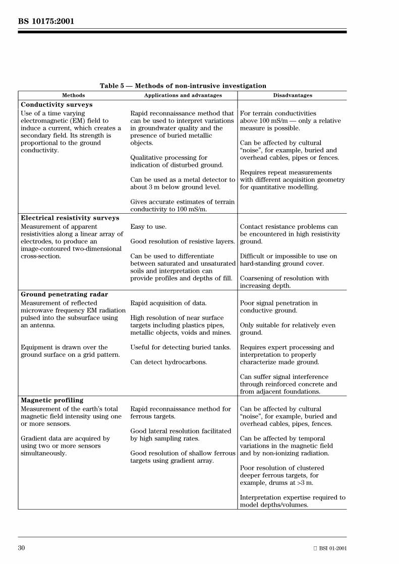
30 BSI 01-2001
BS 10175:2001
Table 5 Ð Methods of non-intrusive investigation
Methods Applications and advantages Disadvantages
Conductivity surveys
Use of a time varyingelectromagnetic (EM) field toinduce a current, which creates asecondary field. Its strength isproportional to the groundconductivity.
Rapid reconnaissance method thatcan be used to interpret variationsin groundwater quality and thepresence of buried metallicobjects.
Qualitative processing forindication of disturbed ground.
Can be used as a metal detector toabout 3 m below ground level.
Gives accurate estimates of terrainconductivity to 100 mS/m.
For terrain conductivitiesabove 100 mS/m Ð only a relativemeasure is possible.
Can be affected by culturalªnoiseº, for example, buried andoverhead cables, pipes or fences.
Requires repeat measurementswith different acquisition geometryfor quantitative modelling.
Electrical resistivity surveys
Measurement of apparentresistivities along a linear array ofelectrodes, to produce animage-contoured two-dimensionalcross-section.
Easy to use.
Good resolution of resistive layers.
Can be used to differentiatebetween saturated and unsaturatedsoils and interpretation canprovide profiles and depths of fill.
Contact resistance problems canbe encountered in high resistivityground.
Difficult or impossible to use onhard-standing ground cover.
Coarsening of resolution withincreasing depth.
Ground penetrating radar
Measurement of reflectedmicrowave frequency EM radiationpulsed into the subsurface usingan antenna.
Equipment is drawn over theground surface on a grid pattern.
Rapid acquisition of data.
High resolution of near surfacetargets including plastics pipes,metallic objects, voids and mines.
Useful for detecting buried tanks.
Can detect hydrocarbons.
Poor signal penetration inconductive ground.
Only suitable for relatively evenground.
Requires expert processing andinterpretation to properlycharacterize made ground.
Can suffer signal interferencethrough reinforced concrete andfrom adjacent foundations.
Magnetic profiling
Measurement of the earth's totalmagnetic field intensity using oneor more sensors.
Gradient data are acquired byusing two or more sensorssimultaneously.
Rapid reconnaissance method forferrous targets.
Good lateral resolution facilitatedby high sampling rates.
Good resolution of shallow ferroustargets using gradient array.
Can be affected by culturalªnoiseº, for example, buried andoverhead cables, pipes, fences.
Can be affected by temporalvariations in the magnetic fieldand by non-ionizing radiation.
Poor resolution of clustereddeeper ferrous targets, forexample, drums at >3 m.
Interpretation expertise required tomodel depths/volumes.
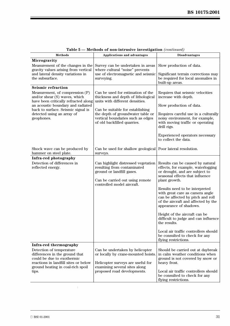
BS 10175:2001
BSI 01-2001 31
Table 5 Ð Methods of non-intrusive investigation (continued)
Methods Applications and advantages Disadvantages
Microgravity
Measurement of the changes in thegravity values arising from verticaland lateral density variations inthe subsurface.
Survey can be undertaken in areaswhere cultural ªnoiseº preventsuse of electromagnetic and seismicsurveying.
Slow production of data.
Significant terrain corrections maybe required for local anomalies inbuilt-up areas.
Seismic refraction
Measurement, of compression (P)and/or shear (S) waves, whichhave been critically refracted alongan acoustic boundary and radiatedback to surface. Seismic signal isdetected using an array ofgeophones.
Can be used for estimation of thethickness and depth of lithologicalunits with different densities.
Can be suitable for establishingthe depth of groundwater table orvertical boundaries such as edgesof old backfilled quarries.
Requires that seismic velocitiesincrease with depth.
Slow production of data.
Requires careful use in a culturallynoisy environment, for example,with moving traffic or operatingdrill rigs.
Experienced operators necessaryto collect the data.
Shock wave can be produced byhammer on steel plate.
Can be used for shallow geologicalsurveys.
Poor lateral resolution.
Infra-red photography
Detection of differences inreflected energy.
Can highlight distressed vegetationresulting from contaminatedground or landfill gases.
Can be carried out using remotecontrolled model aircraft.
Results can be caused by naturaleffects, for example, waterloggingor drought, and are subject toseasonal effects that influenceplant growth.
Results need to be interpretedwith great care as camera anglecan be affected by pitch and rollof the aircraft and affected by theappearance of shadows.
Height of the aircraft can bedifficult to judge and can influencethe results.
Local air traffic controllers shouldbe consulted to check for anyflying restrictions.
Infra-red thermography
Detection of temperaturedifferences in the ground thatcould be due to exothermicreactions in landfill sites or belowground heating in coal-rich spoiltips.
Can be undertaken by helicopteror locally by crane-mounted hoists.
Helicopter surveys are useful forexamining several sites alongproposed road developments.
Should be carried out at daybreakin calm weather conditions whenground is not covered by snow orheavy frost.
Local air traffic controllers shouldbe consulted to check for anyflying restrictions.
32 BSI 01-2001
BS 10175:2001
8.2.3 Intrusive investigation techniques
8.2.3.1 General
See also BS 5930:1999, clauses 19 and 20 for further guidance.
Intrusive investigations involve the collection of samples of soil, groundwater and soil gas and themonitoring of groundwater and soil gas and can be carried out using a variety of techniques.
Probing techniques can be used for the detection and assessment of the distribution of suspectedcontaminants and can be used for screening exercises and where ground disturbance needs to beminimized. Probing may be suitable for investigation at shallow depth and in exploratory investigations.
Trial pits, augers, boreholes and driven samplers can be used to obtain samples for visual inspection andanalysis. Where a monitoring installation is required this may be placed within a borehole.
Intrusive techniques all involve some degree of site disturbance, the greatest with trial pits and the least withdriven samplers. Table 6 gives a variety of techniques which can be used to enable the collection of samplesfrom required depths within the ground with different degrees of accuracy and levels of representativeness.The advantages and disadvantages of these techniques are also given.
Other considerations that should be taken into account when selecting a suitable intrusive method ofinvestigation are given in Figure 2.
8.2.3.2 Environmental considerations
In selecting the sample collection technique, consideration also should be given to preventing the creation ofroutes for migration of contamination (and hence, incurring liability). The migration of contamination can beexacerbated by the formation of routes enabling greater penetration within the ground, but the possibility ofmigration at the surface due to wind blow or exposure of contaminants should also be considered. Ingeneral the deeper the sampling requirement, the greater the risk. All deep sampling locations should bebackfilled with clean low permeability material (for example bentonite grout). Techniques that form uncasedholes should be avoided and monitoring wells or systems should have response zones that are sealed intoindividual aquifers.
Particular care should be taken where low permeability strata (aquicludes) are passed through. The use of adouble penetration technique (forming a larger borehole with a bentonite seal which is then penetrated by asmaller borehole through the seal) to prevent boreholes forming a contamination migration pathway is likelyto be necessary in such circumstances (see also 7.6.3.6).
When forming trial pits, it is good practice to separate the initial surface layer from other excavated material.Excavated material should be reinstated as closely as possible to the depth from which it was removed. Thesurface material should then be replaced to provide a cover.
In order to prevent the site surface becoming contaminated it may be necessary to place the excavatedmaterial on strong sheeting to prevent contact. The sheeting should then be safely disposed of on completionof the backfilling.
Reinstatement of the excavated material in a trial pit involves placing the material in layers and firmlytamping down with the machine bucket. The aim is to compact the material as much as is possible tominimize post reinstatement settlement. Excess material should be heaped over the trial pit so thatsettlement should result in the return of the ground to near the original level. In trafficked areas wherereinstatement of trial pits may cause a problem, use of an alternative technique should be considered inorder to ensure the area will accept likely loadings without settlement.
Care should be taken to ensure that the surrounding area is not affected by contaminated excavated spoilleft after reinstatement. Surface material should be replaced over the trial pit to provide cover and, ifnecessary, clean material should be imported to provide adequate surface cover on completion of backfilling.
Where water is encountered this can result in contaminated groundwater or other liquid, for example oil,being brought to the surface. In these situations, special care is needed to prevent dispersal of thecontaminated water during the investigation and also during subsequent backfilling. It is not recommendedthat trial pits should proceed after water is encountered due to problems relating to the dispersal ofcontaminated water and the poor quality soil samples which will be obtained due to the presence of water(see 8.2.3.3).
Where impermeable cover (for example concrete hardstanding) has been penetrated it may be necessary toreinstate with a suitable low permeability cover to prevent the location becoming a source of ingress ofrainwater resulting in contamination migration.
Where there is surplus excavated material or arisings after backfilling, these should be disposed of with care,if necessary being sent to a suitable disposal site (see 7.4.2).
Examination of a potentially contaminated site may pose risk to the general environment. The work shouldbe planned to prevent the spread of contaminated material by site working clothes, samples, machinery, andvehicle wheels.
BS 10175:2001
BSI 01-2001 33
8.2.3.3 Cross-contamination during sampling
Samples collected for analysis should be as representative as is possible of the material being sampled(see 8.3.2, 8.3.3, and 8.3.4). In addition it is essential that the sample is not contaminated by includingextraneous material as a result of the sampling process, and that equipment and sample containers do notcause contamination nor cause loss of contaminants due to adsorption or volatilization.
When taking samples below surface level in a site it is important that the sample is not affected by material(soil or water) falling from more shallow depths. Thus where trial pits are used the base of the pit should becleared of debris before using the machine bucket to obtain a good sample of the material at the base. Withboreholes and driven tube samplers the base of the hole should be cleared of debris before the sample istaken. With tube samplers this may be difficult and it may be necessary to reject material in the upperportion of the sampling tube which could be affected by debris.
Lubrication of casings and linings has the potential to contaminate the equipment and sample and should beavoided. Where water has to be added to a borehole in order to assist the drilling process, only clean mainswater should be used and the volume should be recorded.
The site works specification should include provision for cleaning equipment between sampling locationsand more frequently if necessary in badly contaminated ground. Cleaning equipment is normally carried outusing pressure jet or steam-cleaning equipment in ground badly contaminated with organic chemicals.Washings from the cleaning process should be collected and then disposed of off-site to a suitable facility(see 7.6).
It is also important that the sampling system and material of the equipment used does not contaminate thesamples or cause loss of contaminants present.
This contamination (or loss of contaminants) can occur, for example, due to the use of incorrect flexibletubing, incorrect plastic materials, and use of unsuitable metal in the sampling equipment or installations.
The operation of equipment, if poorly maintained, or due to lack of cleanliness or even carelessness duringrefuelling, can result in the contamination of samples due to exhaust fumes, lubricating oils or fuel.
A hand trowel of stainless steel should be used to place samples into sample containers. Prior to taking asample, the sampling tool should be cleaned to avoid cross-contamination.
NOTE ISO/DIS 10381-2 also gives guidance.
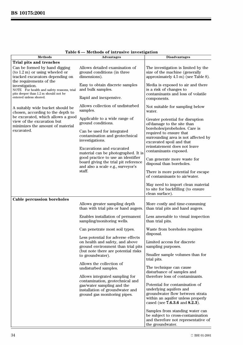
34 BSI 01-2001
BS 10175:2001
Table 6 Ð Methods of intrusive investigationMethods Advantages Disadvantages
Trial pits and trenches
Can be formed by hand digging(to 1.2 m) or using wheeled ortracked excavators depending onthe requirements of theinvestigation.NOTE For health and safety reasons, trialpits deeper than 1.2 m should not beentered unless shored.
A suitably wide bucket should bechosen, according to the depth tobe excavated, which allows a goodview of the excavation butminimizes the amount of materialexcavated.
Allows detailed examination ofground conditions (in threedimensions).
Easy to obtain discrete samplesand bulk samples.
Rapid and inexpensive.
Allows collection of undisturbedsamples.
Applicable to a wide range ofground conditions.
Can be used for integratedcontamination and geotechnicalinvestigations.
Excavations and excavatedmaterial can be photographed. It isgood practice to use an identifierboard giving the trial pit referenceand also a scale e.g., surveyor'sstaff.
The investigation is limited by thesize of the machine (generallyapproximately 4.5 m) (see Table 8).
Media is exposed to air and thereis a risk of changes tocontaminants and loss of volatilecomponents.
Not suitable for sampling belowwater.
Greater potential for disruptionof/damage to the site thanboreholes/probeholes. Care isrequired to ensure thatsurrounding area is not affected byexcavated spoil and thatreinstatement does not leavecontaminants exposed.
Can generate more waste fordisposal than boreholes.
There is more potential for escapeof contaminants to air/water.
May need to import clean materialto site for backfilling (to ensureclean surface).
Cable percussion boreholesAllows greater sampling depththan with trial pits or hand augers.
Enables installation of permanentsampling/monitoring wells.
Can penetrate most soil types.
Less potential for adverse effectson health and safety, and aboveground environment than trial pits(but note there are potential risksto groundwater).
Allows the collection ofundisturbed samples.
Allows integrated sampling forcontamination, geotechnical andgas/water sampling and theinstallation of groundwater andground gas monitoring pipes.
More costly and time-consumingthan trial pits and hand augers.
Less amenable to visual inspectionthan trial pits.
Waste from boreholes requiresdisposal.
Limited access for discretesampling purposes.
Smaller sample volumes than fortrial pits.
The technique can causedisturbance of samples andtherefore loss of contaminants.
Potential for contamination ofunderlying aquifers andgroundwater flow between stratawithin an aquifer unless properlycased (see 7.6.3.6 and 8.2.3).
Samples from standing water canbe subject to cross-contaminationand therefore not representative ofthe groundwater.
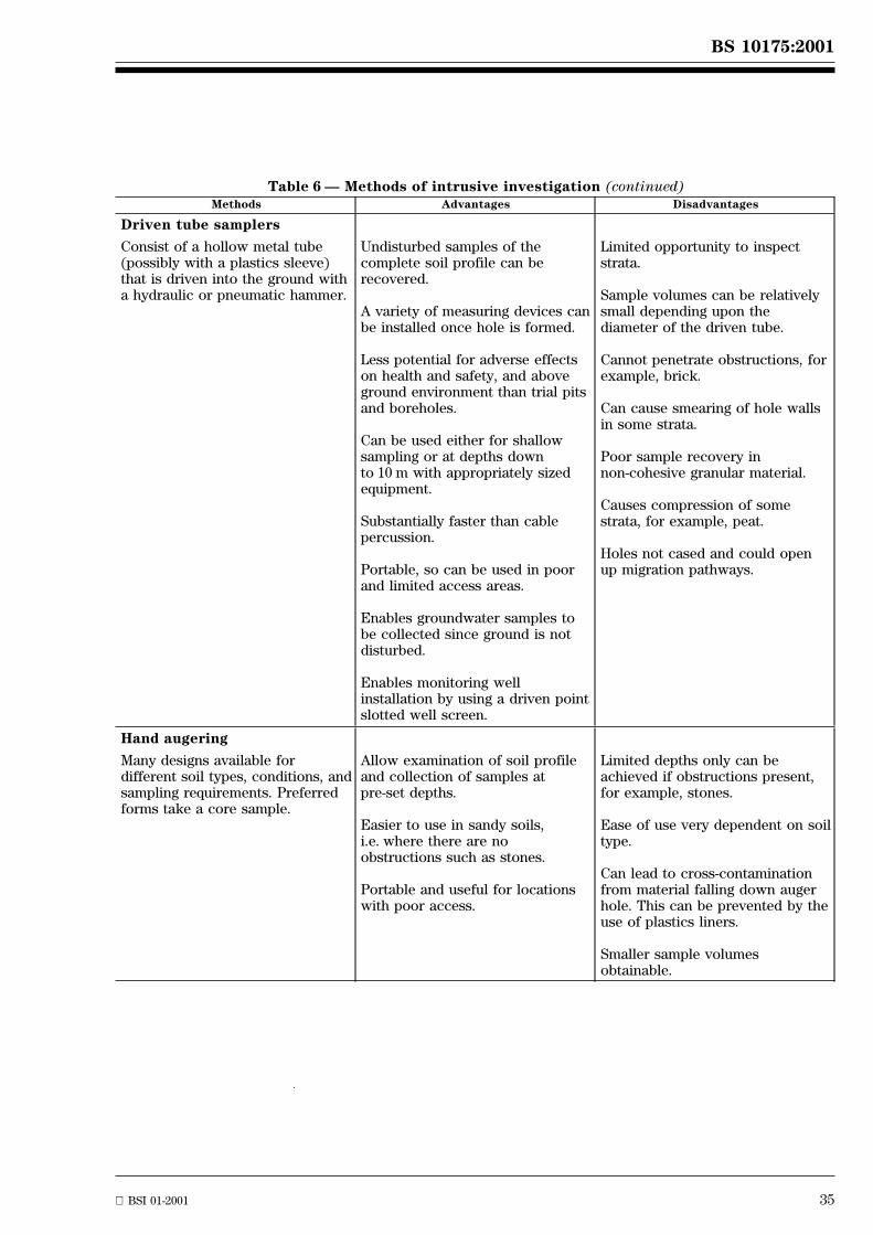
BS 10175:2001
BSI 01-2001 35
Table 6 Ð Methods of intrusive investigation (continued)Methods Advantages Disadvantages
Driven tube samplers
Consist of a hollow metal tube(possibly with a plastics sleeve)that is driven into the ground witha hydraulic or pneumatic hammer.
Undisturbed samples of thecomplete soil profile can berecovered.
A variety of measuring devices canbe installed once hole is formed.
Less potential for adverse effectson health and safety, and aboveground environment than trial pitsand boreholes.
Can be used either for shallowsampling or at depths downto 10 m with appropriately sizedequipment.
Substantially faster than cablepercussion.
Portable, so can be used in poorand limited access areas.
Enables groundwater samples tobe collected since ground is notdisturbed.
Enables monitoring wellinstallation by using a driven pointslotted well screen.
Limited opportunity to inspectstrata.
Sample volumes can be relativelysmall depending upon thediameter of the driven tube.
Cannot penetrate obstructions, forexample, brick.
Can cause smearing of hole wallsin some strata.
Poor sample recovery innon-cohesive granular material.
Causes compression of somestrata, for example, peat.
Holes not cased and could openup migration pathways.
Hand augering
Many designs available fordifferent soil types, conditions, andsampling requirements. Preferredforms take a core sample.
Allow examination of soil profileand collection of samples atpre-set depths.
Easier to use in sandy soils,i.e. where there are noobstructions such as stones.
Portable and useful for locationswith poor access.
Limited depths only can beachieved if obstructions present,for example, stones.
Ease of use very dependent on soiltype.
Can lead to cross-contaminationfrom material falling down augerhole. This can be prevented by theuse of plastics liners.
Smaller sample volumesobtainable.
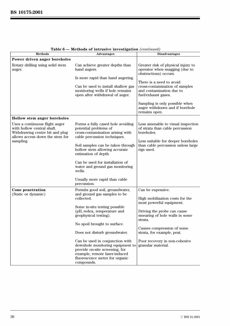
36 BSI 01-2001
BS 10175:2001
Table 6 Ð Methods of intrusive investigation (continued)Methods Advantages Disadvantages
Power driven auger boreholes
Rotary drilling using solid stemauger.
Can achieve greater depths thanhand augers.
Is more rapid than hand augering.
Can be used to install shallow gasmonitoring wells if hole remainsopen after withdrawal of auger.
Greater risk of physical injury tooperator when snagging (due toobstructions) occurs.
There is a need to avoidcross-contamination of samplesand contamination due tofuel/exhaust gases.
Sampling is only possible whenauger withdrawn and if boreholeremains open.
Hollow stem auger boreholes
Uses a continuous flight augerwith hollow central shaft.Withdrawing centre bit and plugallows access down the stem forsampling.
Forms a fully cased hole avoidingpotential problems ofcross-contamination arising withcable percussion techniques.
Soil samples can be taken throughhollow stem allowing accurateestimation of depth.
Can be used for installation ofwater and ground gas monitoringwells.
Usually more rapid than cablepercussion.
Less amenable to visual inspectionof strata than cable percussionboreholes.
Less suitable for deeper boreholesthan cable percussion unless largerigs used.
Cone penetration(Static or dynamic)
Permits good soil, groundwater,and ground gas samples to becollected.
Some in-situ testing possible(pH, redox, temperature andgeophysical testing).
No spoil brought to surface.
Does not disturb groundwater.
Can be used in conjunction withdownhole monitoring equipment toprovide on-site screening, forexample, remote laser-inducedfluorescence meter for organiccompounds.
Can be expensive.
High mobilization costs for themost powerful equipment.
Driving the probe can causesmearing of hole walls in somestrata.
Causes compression of somestrata, for example, peat.
Poor recovery in non-cohesivegranular material.
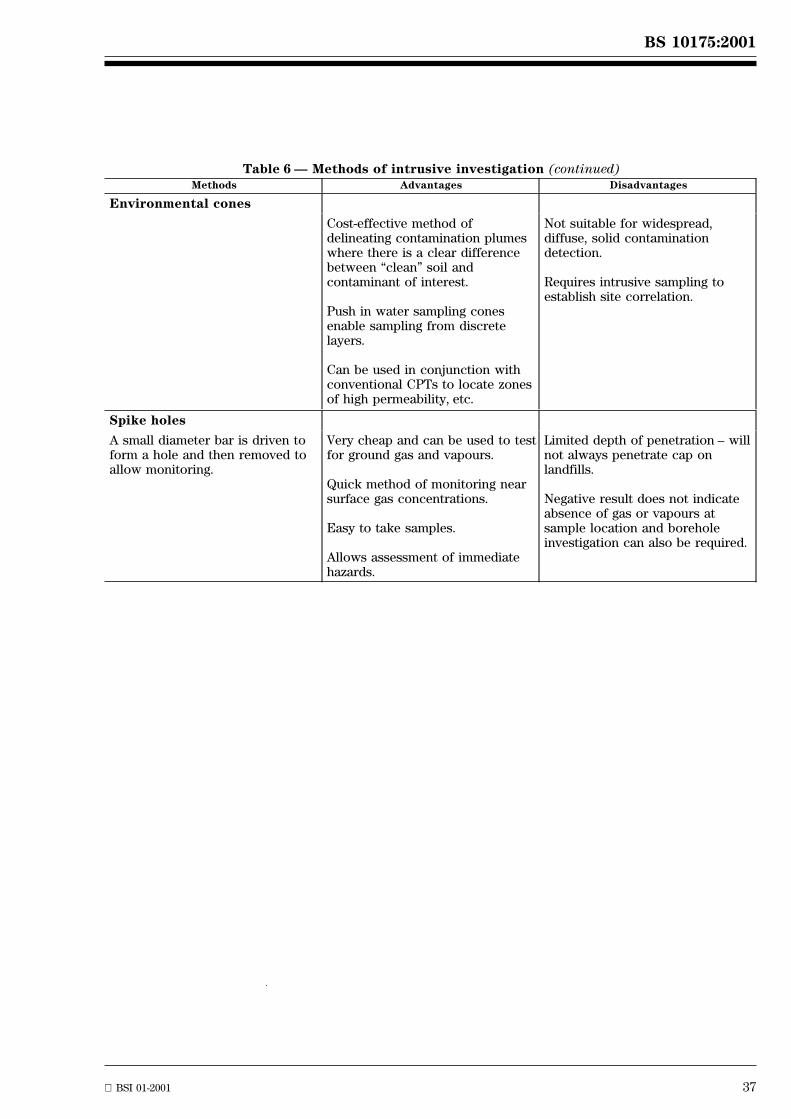
BS 10175:2001
BSI 01-2001 37
Table 6 Ð Methods of intrusive investigation (continued)Methods Advantages Disadvantages
Environmental cones
Cost-effective method ofdelineating contamination plumeswhere there is a clear differencebetween ªcleanº soil andcontaminant of interest.
Push in water sampling conesenable sampling from discretelayers.
Can be used in conjunction withconventional CPTs to locate zonesof high permeability, etc.
Not suitable for widespread,diffuse, solid contaminationdetection.
Requires intrusive sampling toestablish site correlation.
Spike holes
A small diameter bar is driven toform a hole and then removed toallow monitoring.
Very cheap and can be used to testfor ground gas and vapours.
Quick method of monitoring nearsurface gas concentrations.
Easy to take samples.
Allows assessment of immediatehazards.
Limited depth of penetration ± willnot always penetrate cap onlandfills.
Negative result does not indicateabsence of gas or vapours atsample location and boreholeinvestigation can also be required.
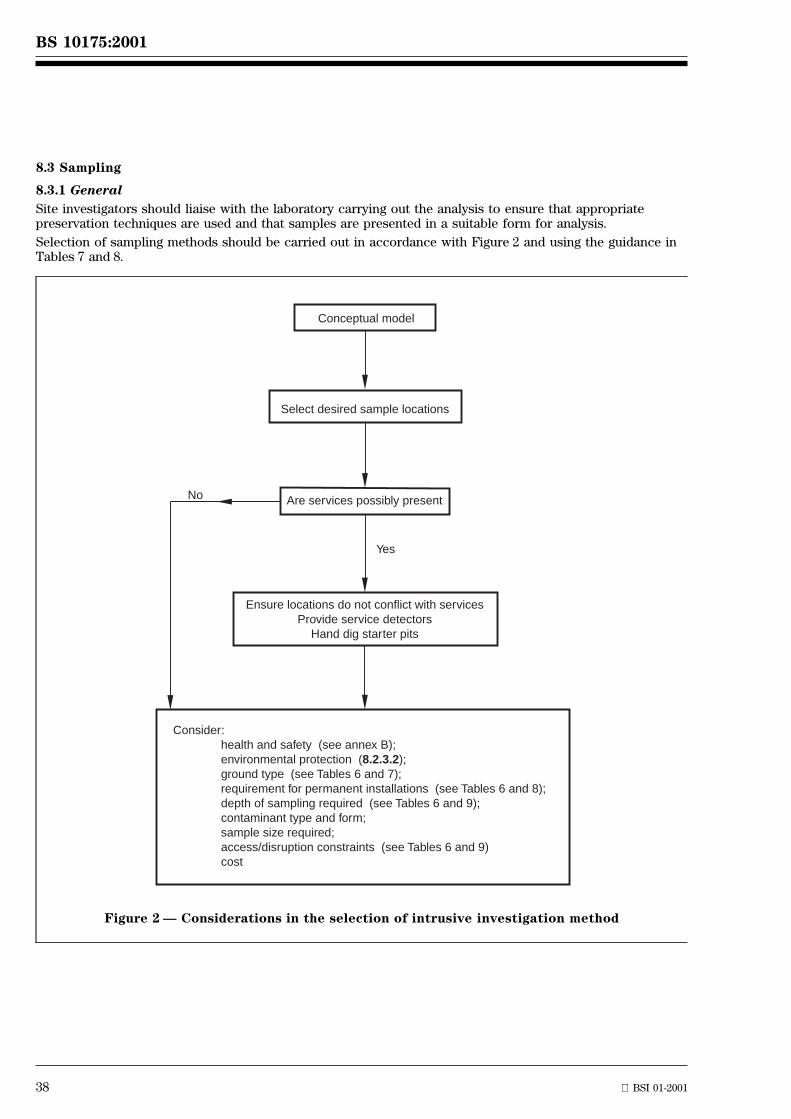
38 BSI 01-2001
BS 10175:2001
8.3 Sampling
8.3.1 General
Site investigators should liaise with the laboratory carrying out the analysis to ensure that appropriatepreservation techniques are used and that samples are presented in a suitable form for analysis.
Selection of sampling methods should be carried out in accordance with Figure 2 and using the guidance inTables 7 and 8.
No
Yes
Conceptual model
Select desired sample locations
Are services possibly present
Ensure locations do not conflict with servicesProvide service detectors
Hand dig starter pits
Consider:health and safety (see annex B);environmental protection (8.2.3.2);ground type (see Tables 6 and 7);requirement for permanent installations (see Tables 6 and 8);depth of sampling required (see Tables 6 and 9);contaminant type and form;sample size required;access/disruption constraints (see Tables 6 and 9)cost
Figure 2 Ð Considerations in the selection of intrusive investigation method
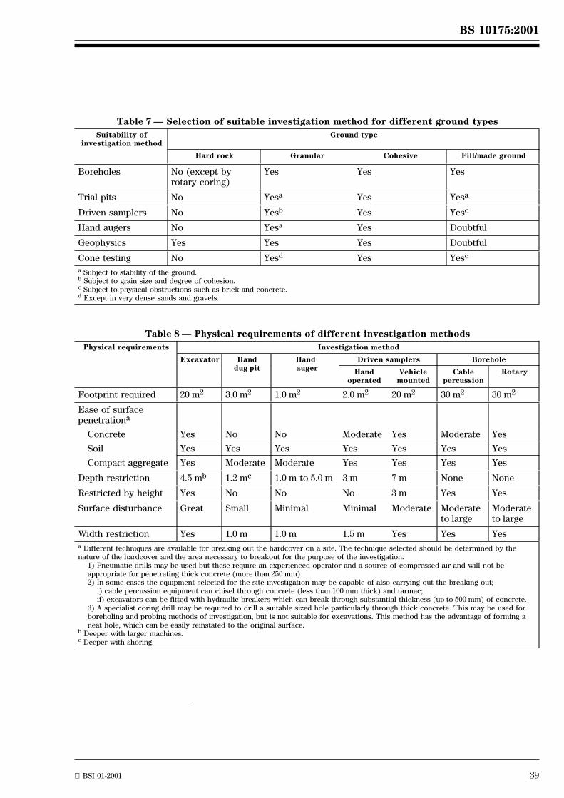
BS 10175:2001
BSI 01-2001 39
Table 7 Ð Selection of suitable investigation method for different ground types
Suitability ofinvestigation method
Ground type
Hard rock Granular Cohesive Fill/made ground
Boreholes No (except byrotary coring)
Yes Yes Yes
Trial pits No Yesa Yes Yesa
Driven samplers No Yesb Yes Yesc
Hand augers No Yesa Yes Doubtful
Geophysics Yes Yes Yes Doubtful
Cone testing No Yesd Yes Yesc
a Subject to stability of the ground.b Subject to grain size and degree of cohesion.c Subject to physical obstructions such as brick and concrete.d Except in very dense sands and gravels.
Table 8 Ð Physical requirements of different investigation methods
Physical requirements Investigation method
Excavator Handdug pit
Handauger
Driven samplers Borehole
Handoperated
Vehiclemounted
Cablepercussion
Rotary
Footprint required 20 m2 3.0 m2 1.0 m2 2.0 m2 20 m2 30 m2 30 m2
Ease of surfacepenetrationa
Concrete Yes No No Moderate Yes Moderate Yes
Soil Yes Yes Yes Yes Yes Yes Yes
Compact aggregate Yes Moderate Moderate Yes Yes Yes Yes
Depth restriction 4.5 mb 1.2 mc 1.0 m to 5.0 m 3 m 7 m None None
Restricted by height Yes No No No 3 m Yes Yes
Surface disturbance Great Small Minimal Minimal Moderate Moderateto large
Moderateto large
Width restriction Yes 1.0 m 1.0 m 1.5 m Yes Yes Yesa Different techniques are available for breaking out the hardcover on a site. The technique selected should be determined by thenature of the hardcover and the area necessary to breakout for the purpose of the investigation.
1) Pneumatic drills may be used but these require an experienced operator and a source of compressed air and will not beappropriate for penetrating thick concrete (more than 250 mm).2) In some cases the equipment selected for the site investigation may be capable of also carrying out the breaking out;
i) cable percussion equipment can chisel through concrete (less than 100 mm thick) and tarmac;ii) excavators can be fitted with hydraulic breakers which can break through substantial thickness (up to 500 mm) of concrete.
3) A specialist coring drill may be required to drill a suitable sized hole particularly through thick concrete. This may be used forboreholing and probing methods of investigation, but is not suitable for excavations. This method has the advantage of forming aneat hole, which can be easily reinstated to the original surface.
b Deeper with larger machines.c Deeper with shoring.
40 BSI 01-2001
BS 10175:2001
8) More information can be obtained from the Macaulay Land Use Research Institute, Craigiebuckler, Aberdeen, AB15 8Q.
8.3.2 Collection of soil samples
Whenever a site is to be characterized, it is not possible to examine the whole site and it is thereforenecessary to take samples. The samples collected should be as representative as possible of the material atthe location and depth being sampled. A representative sample may be obtained by collecting a number ofclosely spaced incremental samples. The increments should be of equal size and equally spaced in aprescribed pattern (see annex D). The resultant sample should be more representative of the location beingsampled than a single sample, particularly if the material is highly variable. This method of collecting arepresentative sample is particularly appropriate when using trial pits. When using boreholes or tubesamplers the material drawn from the ground is more limited and it will be important to ensure that thesample is actually from the depth recorded and that it is free from extraneous material from other depths.
When collecting samples for the determination of volatile compounds the sampling technique shouldminimize the loss of volatiles and may require the collection of an undisturbed sample (see below).
For contamination investigations, a sample of 1 kg to 2 kg should be taken, which should be adequate formost analytical suites. Where the sample is of coarse grained material, for example gravels, a larger samplemay be necessary. Additional samples of different size may also be necessary, for example to enable thedetermination of volatile hydrocarbons. The size of such samples should be agreed with the testinglaboratory to ensure that the sample is of an appropriate size. With smaller volumes of sample, it may bemore difficult to ensure that the sample is representative and there may need to be a compromise, forexample between the level of representation and avoiding the loss of volatile components. Larger samplesmay be necessary for geotechnical testing (see BS 5930, clause 22).
Precautions should be taken to prevent the samples undergoing any changes during sampling includingcross-contamination, or during the interval between sampling and analysis.
Samples collected for the purposes of investigating soil and ground conditions are generally disturbedsamples. These are obtained from the ground without any attempt to preserve the soil structure, i.e. the soilparticles are collected ªlooseº and are allowed to move in relation to each other.
Disturbed samples can be taken by any of the three basic methods outlined in Table 9 since such samples donot require maintenance of the original ground structure. Such samples should be transferred to theappropriate sample container using an inert tool such as a stainless steel trowel.
Where loss of soil structure is likely to affect the subsequent examination, for example microbiologicalexaminations, certain physical measurements and determination of volatile organic compounds, undisturbedsamples should be collected.
Undisturbed samples are samples obtained from the ground using special sampling equipment or techniquesto preserve the soil structure, i.e. the soil particles and voids are not allowed to change from the distributionthat existed in the ground before sampling.
Undisturbed samples should be taken using a coring tool or cylinder (U100) or with a KubieÈna Can8). Thesampling device should be pushed into the soil and removed complete with the sample so that soil iscollected in its original physical form.
8.3.3 Collection of water samples
8.3.3.1 General
Water samples collected from trial pits and boreholes at the time of formation are unlikely to provide areliable representation of groundwater quality due to the ground disturbance affecting the composition of thewater. However, such samples can provide some preliminary information which assists in the design of asubsequent groundwater monitoring programme. The water can contain a substantial amount of suspendedparticles that require field filtration or settlement before analysis. To overcome this, a larger than requiredvolume of sample may be necessary to compensate for the volume of material that will be removed bysettlement.
Sample pre-treatment should be carefully considered to ensure that the sample for analysis represents thewater body and does not contain suspended soil particles.
If the presence of organic materials (oils, solvents, etc.) is not a consideration, the sample may be collectedusing a bailer. However, undue aeration of the sample (resulting in erroneous dissolved oxygen results, orthe induced oxidation of certain components) can occur if using a top-filling bailer.
Surface water sampling should be carried out in accordance with BS EN 25667-1 (dual numbered asBS 6068-6.1), BS EN 25667-2 (dual numbered as BS 6068-6.2) and BS 6068-6.6. Groundwater sampling shouldbe carried out in accordance with BS 6068-6.11.NOTE ISO/DIS 5667-18 also gives guidance on groundwater sampling.
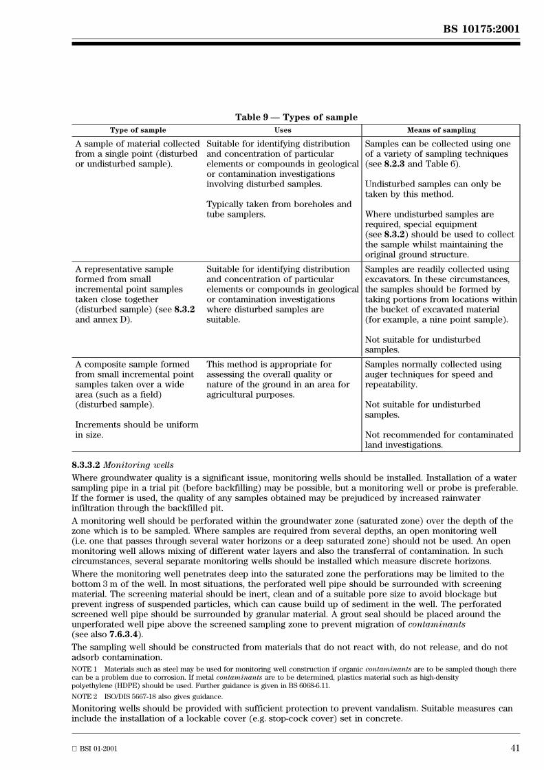
BS 10175:2001
BSI 01-2001 41
Table 9 Ð Types of sample
Type of sample Uses Means of sampling
A sample of material collectedfrom a single point (disturbedor undisturbed sample).
Suitable for identifying distributionand concentration of particularelements or compounds in geologicalor contamination investigationsinvolving disturbed samples.
Typically taken from boreholes andtube samplers.
Samples can be collected using oneof a variety of sampling techniques(see 8.2.3 and Table 6).
Undisturbed samples can only betaken by this method.
Where undisturbed samples arerequired, special equipment(see 8.3.2) should be used to collectthe sample whilst maintaining theoriginal ground structure.
A representative sampleformed from smallincremental point samplestaken close together(disturbed sample) (see 8.3.2and annex D).
Suitable for identifying distributionand concentration of particularelements or compounds in geologicalor contamination investigationswhere disturbed samples aresuitable.
Samples are readily collected usingexcavators. In these circumstances,the samples should be formed bytaking portions from locations withinthe bucket of excavated material(for example, a nine point sample).
Not suitable for undisturbedsamples.
A composite sample formedfrom small incremental pointsamples taken over a widearea (such as a field)(disturbed sample).
Increments should be uniformin size.
This method is appropriate forassessing the overall quality ornature of the ground in an area foragricultural purposes.
Samples normally collected usingauger techniques for speed andrepeatability.
Not suitable for undisturbedsamples.
Not recommended for contaminatedland investigations.
8.3.3.2 Monitoring wells
Where groundwater quality is a significant issue, monitoring wells should be installed. Installation of a watersampling pipe in a trial pit (before backfilling) may be possible, but a monitoring well or probe is preferable.If the former is used, the quality of any samples obtained may be prejudiced by increased rainwaterinfiltration through the backfilled pit.
A monitoring well should be perforated within the groundwater zone (saturated zone) over the depth of thezone which is to be sampled. Where samples are required from several depths, an open monitoring well(i.e. one that passes through several water horizons or a deep saturated zone) should not be used. An openmonitoring well allows mixing of different water layers and also the transferral of contamination. In suchcircumstances, several separate monitoring wells should be installed which measure discrete horizons.
Where the monitoring well penetrates deep into the saturated zone the perforations may be limited to thebottom 3 m of the well. In most situations, the perforated well pipe should be surrounded with screeningmaterial. The screening material should be inert, clean and of a suitable pore size to avoid blockage butprevent ingress of suspended particles, which can cause build up of sediment in the well. The perforatedscreened well pipe should be surrounded by granular material. A grout seal should be placed around theunperforated well pipe above the screened sampling zone to prevent migration of contaminants(see also 7.6.3.4).
The sampling well should be constructed from materials that do not react with, do not release, and do notadsorb contamination.
NOTE 1 Materials such as steel may be used for monitoring well construction if organic contaminants are to be sampled though therecan be a problem due to corrosion. If metal contaminants are to be determined, plastics material such as high-densitypolyethylene (HDPE) should be used. Further guidance is given in BS 6068-6.11.
NOTE 2 ISO/DIS 5667-18 also gives guidance.
Monitoring wells should be provided with sufficient protection to prevent vandalism. Suitable measures caninclude the installation of a lockable cover (e.g. stop-cock cover) set in concrete.
42 BSI 01-2001
BS 10175:2001
8.3.3.3 Well cleaning and development
After installation, monitoring wells should be developed using a pump, bailer or surge block to remove anymaterials or contaminants that might have entered the well during installation. This development also settlesthe granular surround and ensures free flow of liquids through the well screen. The rate of pumping shouldbe substantially greater than that proposed for subsequent purging or sampling. Development shouldcontinue until the water is visibly clean and/or of constant quality, for example in terms of its electricalconductivity.
It is important that consideration is given to the disposal of water from well development and purging, sinceit can be contaminated.
Adequate provision for the disposal of contaminated water from monitoring wells should be made(see 7.4.2).
Samples of groundwater should be collected after allowing sufficient time for equilibrium to be reached. Aperiod of at least 14 days should be allowed after installation and development for equilibration. However,there are occasions where such an equilibration period is not possible. In this case, the sample should betaken after allowing the maximum possible time for equilibration.
NOTE The use of cement/bentonite grouts in monitoring well construction can affect the water chemistry, for example, pH. Sufficientequilibration time should be allowed to minimize any such effects. This effect may be long lasting requiring the installation of anothermonitoring well.
8.3.3.4 Purging
One of the most important aspects of monitoring is to collect a representative sample. Water within amonitoring well that has not been recently purged, is not always representative of water in the surroundingstrata for a variety of reasons, including oxidation and loss of volatiles. Purging should therefore,immediately precede any sampling, to remove stagnant water.
The impact of purging should be considered alongside the benefits of improved sample integrity. Forexample, where contaminants are present at discrete locations or free phase contamination involvingLNAPLs and DNAPLs is present, purging can redistribute or spread the contaminants. This can lead either toerroneous results or an exacerbation of the initial problem. In such cases micro-purging should beconsidered. In addition, or alternatively, samples of pre- and post-purge water may be collected during theearly stages of an investigation to compare results. This information can then be used to optimize subsequentsampling.
Purging should be undertaken at a flow rate less than was used for development of the well and greater thanthat proposed for sampling. It should continue until the pH, temperature and conductivity of the purgedwater have stabilized (i.e. until any two successive readings are within 10 % of each other), until three wellvolumes of water have been removed or until some other criterion indicating a representative sample can beobtained, is met. For the purposes of this standard well volume is the volume of water within a standpipeand the gravel pack surround.
Micro-purging techniques (where the water column above the pump intake is not disturbed, and water isdrawn locally at a very low flow rate) may be used. Purging by this means may be carried out using anon-displacement pump (such as a bladder pump) at a flow rate that minimizes drawdown to the system.Typical flow rates at the pump intake for both low flow purging and sampling are in the order of 0.1 l/minto 0.5 l/min depending upon the site-specific hydrogeology.
When using micro-purging techniques the time or purge volume required to stabilize pH, conductivity andtemperature is independent of well depth or well volume. Purging should continue until successive readingshave stabilized.
Micro-purging should ideally be carried out using dedicated pumps, as passing a pump through the watercolumn causes mixing and disturbance. Bailers, grab samplers and inertial pumps are not suitable formicro-purging and sampling.
Water level and depth of well measurements should be taken after sampling in order to avoid disturbance ofthe water column.
8.3.3.5 Sampling
Samples may be taken by pump, bailer, depth sampler or similar device depending on the depth of thegroundwater and the parameters to be determined (for further guidance, see BS 6068-6.11). Where apermanent sampling pump is installed, samples of groundwater can be readily collected over a period of timeso that gradual changes in groundwater quality can be identified.
NOTE ISO/DIS 5667-18 also gives guidance.
BS 10175:2001
BSI 01-2001 43
Disposable bailers may be used to avoid cross-contamination.
If oil or other immiscible liquids (LNAPLs) are present floating on the water, it is difficult to obtain a samplethat accurately represents the proportion of oil to water. It can be appropriate to collect a sample of thewater beneath the oil for analysis (using a depth sampler or dedicated pump, for example, an inertial pump),and also a sample of the floating layer for examination. The depth of the floating layer can be measured withan interface meter.
The thickness of a LNAPL floating in a borehole will be greater than the actual thickness of the layer in theaquifer due to the tendency for accumulation to occur in a borehole.
When sampling through the thickness of oil or other immiscible liquid, a ªverticalº column sample should betaken using a sampling tube. The tube should be inserted to a measured depth and sealed at top and bottombefore removal. The sampling device should then be returned to the laboratory for analysis due to thedifficulty of removing the oil quantitatively.
Special sampling and sample preservation techniques should be used when sampling for certaincontaminants. Volatile organic compounds such as solvents, inorganic compounds which are affected byoxidation (iron and sulfides) or volatility (cyanides) and metals (which could require filtration andacidification on site) are examples of such contaminants. Some guidance is given in BS EN ISO 5667-3(dual numbered as BS 6068-6.3), but the advice of the analytical laboratory should be obtained.
Samples of groundwater should be analysed for pH, temperature and conductivity on site. Other parameters,for example, dissolved oxygen or nitrite, may also be determined on site. The advice of the analyticallaboratory should be obtained.
Where it is necessary to obtain samples of pore water in the unsaturated zone, a piezometer with a ceramicor plastics tip should be installed. Care should be taken to avoid the installation penetrating the saturatedzone. Alternatively, a large undisturbed soil sample may be collected and the pore water removed byfiltration, or by using a diaphragm or centrifuge.
8.3.4 Gas samples
Detection and determination of soil gases can be undertaken by (see 7.6.4):
Ð monitoring in the field; or by
Ð sampling the soil gas and subsequent analysis in the laboratory or field.
In most cases, the composition and flow rates of gas will be of primary interest in the assessment of risks. Insome circumstances, the purging of monitoring wells to obtain a sample of pore space gas will be required,for example, if gas quality is being assessed with respect to power generation.
At the time of sampling, various observations should be made and recorded to aid data interpretation. Theseinclude:
Ð measurement of pressure in, and gas flow from, the monitoring well;
Ð depth to groundwater;
Ð atmospheric pressure;
Ð atmospheric pressure for the preceding three days (to show the change in pressure);
Ð weather conditions;
Ð the state of the ground (dry, wet, covered with snow, etc.)
Gas flow rates should be measured using equipment capable of accurately measuring the likely gas flow. Inparticular, where little or no flow is expected the equipment should be capable of measuring low flow ratesin the order of millilitres per hour.
Samples of soil gas for analysis for permanent gases (for example, methane, oxygen or carbon dioxide)should be transferred to a pressurized metal cylinder (for example, stainless steel or aluminium) using handpumps. Lower pressure samples should be collected using gas-sampling bags made from inert material.Where a large volume is required, for example for radio-carbon dating, a large tyre inner tube may be used.
44 BSI 01-2001
BS 10175:2001
Where collection of soil gas samples for the identification and determination of volatile organic carboncompounds is necessary, the compounds should be adsorbed onto a sampling medium such as activatedcarbon or similar and subsequently determined in a laboratory. The choice of adsorption medium willdepend on the volatile compound being sampled. The laboratory staff should be consulted when choosing anappropriate adsorption medium.
NOTE 1 On-site testing is frequently non-specific, for example, using total flammable gas detectors and photo-ionization detectors.Under certain circumstances, infra-red technology can be used to determine specific substances, (subject to the limitations of theinstruments declared by the manufacturer). Any instrument used should achieve appropriate limits of detection and the limitations andpotential interferences should be clearly understood. Proprietary chemical indicator detector tubes are available for a wide range ofgases. Hot wire type catalytic gas detectors and flame ionization detectors are affected by low oxygen content for methanemeasurements.
NOTE 2 Hydrogen sulfide can be an important component of the gas sample. Measurements should always be carried out on-site dueto the difficulty of providing an unaltered sample for laboratory analysis. (This does not preclude the use of laboratory analysis forhydrogen sulfide providing any discrepancy with on-site results is carefully investigated.)
8.4 On-site testing
8.4.1 General
In most investigations, the samples collected from the site should be sent to a laboratory for detailedexamination. There are, however, some occasions when testing may be carried out on the site itself. Theseinclude the following applications:
a) the detection and initial assessment of contaminants (such as toxic or flammable gases and volatilesolvents) at locations identified during the reconnaissance and which could present hazards for furtherwork on the site;
b) the determination of contaminant concentration or properties that can alter between collection andlaboratory analysis; for example, pH, redox potential, dissolved oxygen content, electrical conductivity, orturbidity of liquid samples;
c) the rapid analysis of soil, fill materials or groundwater excavated during site clearance, development orremediation, (in order to inform decisions on disposal or retention);
d) the initial delineation of possible localized areas of high concentrations of contaminants;
e) screening of a large number of samples to reduce unnecessary laboratory costs, for example, screeningground samples for volatile organic compounds using a photo-ionization detector to ensure that onlysamples of relevance are submitted for analysis;
f) helping to determine the positions of further sampling points.
8.4.2 On-site screening
8.4.2.1 General
This subclause describes various commonly used screening methods and identifies some inherent limitations.The selection is not definitive or exhaustive, but highlights considerations that should be taken into accountwhen using these tests. The results produced by on-site instrumentation should be reported in conjunctionwith calibration information and records of quality control performance. The quality control requirements ofsuch work should be no less demanding than those for work undertaken in a laboratory. The benefits ofcarrying out on-site screening can only be achieved if the quality of the work is controlled in the field andreported in the same manner as it would be in a permanent laboratory.
8.4.2.2 Soil samples
8.4.2.2.1 Metals
X-ray fluorescence (XRF) can be used but requires laboratory space since the sample moisture contentrequires control. Detection limits for some metals, for example, cadmium, are not always sufficiently low toprovide adequate on-site information. Where the x-ray source is an isotope, the operator requires a licenceand a 240 V electricity source will also be necessary.
8.4.2.2.2 Mineral oils, polychlorinated biphenyls (PCBs)
Screening for mineral oils and PCBs using field kits usually involves solvent extraction followed either by achemical reaction, or by immuno-assay. The results are useful for indicating whether a target value has beenreached, for example in a remediation scheme, or whether there is a likelihood of the presence ofcontamination which requires sampling and laboratory analysis (for example, PCBs). Immuno-assaytechniques are usually based on selected concentrations so that the presence of contamination is identifiedas, for example, less than 1 mg/kg, between 1 mg/kg and 20 mg/kg, or greater than 20 mg/kg.
BS 10175:2001
BSI 01-2001 45
9) National Radiological Protection Board, Chilton, Didcot, Oxon OX11 0RQ. Tel 01235 831 600.
8.4.2.2.3 Volatile organic compounds by headspace analysis
8.4.3 Water samples
Portable direct-reading analysers, (usually based upon electrochemical principles), can be used to measuresample properties that change rapidly after removal from the local environment and following atmosphericexposure. The instruments use sensors or probes that are either placed directly into the liquid prior tosample collection, or into the sample bottles after collection. The following properties and constituents canbe determined with such instruments: pH, electrical conductivity, redox potential, temperature, dissolvedoxygen concentration, ammonia concentration.
8.4.4 Gas samples
On-site testing of gas/atmosphere is frequently carried out. This enables detection and measurement of easilyoxidized and reactive gases (for example, hydrogen sulfide), without risk of decomposition in the samplecontainer.
Monitoring of gas composition can be carried out with instruments in a mobile laboratory. This equipment isconnected by sampling tube, to different sample locations, and then continuously records changes in thecomposition. More typically, monitoring is carried out on-site using portable instruments with samples alsobeing collected and returned to a laboratory for compositional confirmation analysis (see 8.3.4). Thefollowing instruments can be used.
a) Flame ionization detectors (FIDs) and flammable gas detectors
These instruments respond to the presence of volatile organic compounds and are used for monitoring andquantification. The concentration recorded is expressed in terms of the compound used for calibration.For example, when monitoring for methane, the equipment should be calibrated with methane. Adrawback is that other volatile organic compounds can also give a response. Confirmation that theresponse is actually due to the presence of methane and not due to another organic compound is thereforenecessary. The response is related to the vapour pressure of the compound and some materials such asdiesel or gas oil, although odorous, will not give a large response.
b) Photo-ionization detectors (PIDs)
These instruments can be fitted with different lamps to vary the response to different groups ofcompounds, for example, chlorinated hydrocarbons or aromatics (benzene, toluene or xylene). However,the equipment does not measure these groups of compounds exclusively and results, therefore, should beinterpreted with care. As with FID, the instrument reading is presented in terms of the vapour used forcalibration and diesel and gas oil will not give a large response. A PID is not suitable for detection ofmethane.
8.4.5 Radioactivity
If the site history indicates that radioactive substances have been, or are, present it is essential thatappropriate precautions are taken during any work on the site including the reconnaissance visit. Mostradioactive contamination on the surface of the site can be identified using portable instruments to detectalpha, beta, gamma and, if necessary, neutron emissions. Gamma emissions from buried material can also bedetected by such instruments. Soft beta emissions (particle energy less than about 200 keV) cannot bedetected with such equipment and require a laboratory assay of samples, as do specific activitydeterminations.
All testing for radioactive contamination should be carried out by suitably trained personnel and, ifnecessary, specialist advice should be obtained from National Radiological Protection Board9).
8.5 Sample containers
When sampling an area of potential contamination it is essential that the material of the sample containerdoes not affect the sample. The container used should not cause contamination of the sample, should notabsorb any sample components (for example organic compounds) and should not allow losses of volatilecomponents.
The containers usually used for routine work with soils are plastics ªbucketsº (polyethylene orpolypropylene) with fitted lids, with a capacity of 1 kg to 2 kg of solid sample.
Where organic compounds are to be determined, inert containers, which prevent loss by absorption, orvolatilization, should be used. Wide-mouthed glass containers, screw capped aluminium containers or tinswith press on lids and sealed U100 tubes are suitable.
46 BSI 01-2001
BS 10175:2001
In addition to keeping the sample secure, the container should also allow the sample to be accessed foranalysis without loss of volatile components. The laboratory carrying out the analysis should be consultedbefore selecting the container.
Vapour seal caps should be used where headspace analysis is to be carried out.
Water samples should be collected in PET (polyethylene terephthalate) or glass bottles. For moreinformation on appropriate sampling containers for waters, see BS 6068.
It is prudent to have different sizes and types of container available on site so that if unexpected materialsare encountered they can be properly sampled.
8.6 Sample labelling, preservation and handling
Once a sample is obtained, it should be clearly and uniquely labelled (for example on the side of thecontainer and the lid).
The following labelling methods may be used:
Ð tie on labels or adhesive labels (providing there is adequate adhesion of the label under on-siteconditions);
Ð writing directly on the sample container;
Ð placing a label inside the container (providing it is suitably protected from the contents).
The labels used should be resistant to external influences (rain, contamination, etc.), and to future treatment(abrasion, handling, contact with chemicals, etc.). The labels should be large enough to contain all therelevant information in a legible form. Some commercially available adhesive labels and marker pens containorganic solvents. Care should be taken to avoid absorption of these solvents. This is not likely to be asignificant problem with soil samples, but in the case of gas or water samples, can result in contamination ofthe sample.
Before samples are dispatched from the site (and also upon receipt at the laboratory), the details on thecontainer (and lid if necessary) should be checked against the sample report and chain of custodydocuments.
The preservation and handling of water should be carried out in accordance with BS EN ISO 5667-3(dual numbered as BS 6068-6.3). The laboratory performing the analysis should be consulted before samplingto ensure that appropriate preservation and handling techniques are used. This will ensure that anyrequirements specific to the analytical method can be taken into account.
NOTE Further specific guidance is given in BS 6068-6.6.
Preservation and handling of soil and other solid samples should generally be dealt with on amethod-specific basis. If not all potential contaminants have been identified prior to sampling, soils shouldbe refrigerated at 4 8C ± 2 8C, in the dark, during intermediate stages of storage and transit to the laboratory.When cooled, the samples will retain their field composition and properties far better.
Carriers of samples between site and laboratory should be advised of the identity of materials they arehandling, in line with appropriate labelling requirements. Samples should be transported to the laboratory asquickly as possible to minimize any potential for chemical and biological changes to take place beforeexamination, and in any case within 24 hours for time dependent analytes such as COD and BOD.
8.7 Sampling report
The person taking the sample should record details of the samples on the containers at the time ofcollection, in accordance with the requirements of the investigation.
The ground strata should be logged on site during the formation of the trial pit, auger, bore or probehole.Location within the site should be recorded as the samples are taken. The descriptions of ground used forrecording the strata should conform to the categories used in BS 5930 but should also include any additionalobservations that are relevant to the contamination investigation. BS 5930:1999, 41.4.5 gives advice on howdescriptions of made ground should be formed. If additional or special samples are taken, the reasons shouldbe recorded. A description of each sample taken should also be recorded.
Where a sampling location has to be moved, the actual location should be noted and the reason for therelocation stated.
Any other on-site observations should also be included in the report, as these can be useful in thesubsequent interpretation of any analytical data. Where gas monitoring or sampling has been carried out, thevarious observations required (see 8.3.4) are particularly valuable and should be recorded on site and as apart of the sample report.
BS 10175:2001
BSI 01-2001 47
The following information, (where relevant to a site), should be included in the sampling report:
a) location and name of the sampling site with co-ordinates and other relevant locational informationincluding ground levels;
b) details of the actual sampling locations, including co-ordinates and depth;
c) date of collection;
d) method of collection;
e) time of collection;
f) name of collector;
g) weather conditions;
h) nature of any pre-treatment;
i) barometric pressure;
j) ambient temperature;
k) any other data or observations gathered during the sampling process.
9 Off-site analysis of samples
9.1 General
Methods validated for the analysis of contaminated sites should be used whenever possible. Suitablemethods are contained in BS 1017, BS 1377, BS 1747, BS 6068 and BS 6069. BS 7755 and BS 8855 containmethods that have been specifically developed for the purpose of analysing contaminated land. Furtherguidance on methods suitable for the analysis of samples from potentially contaminated sites can be found inthe following publications.
Ð Methods for the Examination of Water and Associated Materials published by the EnvironmentAgency ± Standing Committee of Analysts [33];
Ð Methods of analysis published by MAFF [34];
Ð Methods for the determination of hazardous substances published by the Health and SafetyExecutive [35]; and
Ð Digest 363 published by the Building Research Establishment [36].
Guidance on suitable methods of analysis for substances may be drawn from other authoritative texts.However, it should be noted that the principle of fitness for purpose should be applied to any methodchosen. Where necessary, appropriate validation procedures should be applied, using typical sample matricesto assess the suitability of chosen methods. Consultation with an analytical laboratory (preferably the onethat will eventually carry out the chemical testing) is advisable to assist in the selection of appropriatetesting methods.
It is important that the methods of test provide a detection limit substantially below the concentration ofinterest for a given parameter (ideally the detection limit should be at least ten times lower than theconcentration of interest).
Where several analytical methods are available for the determination of a particular parameter, the choice ofmethod should take into account chemical interferences and matrix effects. The choice should be basedupon the ability of the selected method to determine the contaminant of interest with adequate accuracyand precision, over the concentration range expected to be present.
Whenever comparisons are to be made with formal guidelines or standards, the specified analytical methodsshould be employed. Variation from a prescribed method can only be justified if the alternative techniquecan be demonstrated to have an equivalent performance and that its use will not significantly influenceinterpretation or risk assessment outcome.
9.2 Choice of laboratory
The laboratory chosen should be competent in the analyses to be carried out. Competence can bedemonstrated by third party accreditation but it should be noted that such accreditation is usually on amethod-specific basis. A check that the laboratory is specifically accredited for the test parameters ofinterest, should be undertaken before commissioning any analysis. It is desirable that the laboratoryparticipates in external proficiency testing schemes relevant to the work being commissioned and usesreference materials to validate and check analytical methods. Obtaining brief method statements for theproposed method of analysis gives an opportunity to check that it will be possible to interpret resultscorrectly at a later date.
48 BSI 01-2001
BS 10175:2001
9.3 The assessment and control of errors in sub-sampling and analysis
9.3.1 General
It should be remembered that the results of the analysis in relation to assessing the degree of contaminationcan only be as good as the representativeness of the sample and hence only as good as the design of thesampling strategy and the sampling technique. Confidence in the representativeness of the sampling can bejustified by collecting and analysing duplicate samples, for example on a one in 20 sample basis.
9.3.2 Sub-sampling errors
Samples submitted to the laboratory sometimes require preparation or pre-treatment. However, for everysample, a sufficiently homogeneous and representative sub-sample should be analysed. This can be relativelystraightforward if the whole sample is dried and ground, for example for metals determination. However, itis much more difficult to prepare a representative sub-sample of a heterogeneous sample (for example, amixture of clay and granular ash) for the determination of volatile components. Loss of any componentswhilst preparing a sub-sample can result in inaccurate results. It can be advisable to collect the originalsample (a known amount) into a known volume of solvent for subsequent analysis.
Where a heterogeneous sample is submitted for analysis, the component parts should be recorded. Any inertmaterial for exclusion from the analysis should be recorded as a percentage of the sample.
Procedures for the preparation (drying, grinding, etc.) or stabilization of samples should normally be carriedout in the laboratory before a portion of the homogenized sample (i.e. the sub-sample) is taken for analysis.Care should be taken to avoid cross-contamination during preparation to prevent uncontaminated samplesbeing adversely affected by highly contaminated samples.
Consideration should be given to the preparation of duplicate sub-samples (on a batch, or a one samplein 20 basis, for example) for duplicate analysis to assess the reliability of the sub-sampling procedures.
Guidance on estimating the reliability of such procedures is described in BS 1017-1.
9.3.3 Analytical errors
The analytical laboratory should be asked to demonstrate that the methods used are suitable and appropriateto the needs of the investigation and are fit for their intended purpose. The analytical laboratory should alsobe asked to demonstrate that adequate quality control procedures are applied routinely to the methods inuse and that the performance of the method is well established.
Further guidance on analytical quality control can be found in DD ENV 13530.
The analytical report should include details of the quality control procedures adopted for the analysesreported. It is good practice to carry out the analysis of control samples, reference samples and blanks.
NOTE Errors associated with the use of analytical methods are usually well documented and less significant than the variabilityassociated with sampling and sub-sampling (see 7.6.1). However, when analytical data are reviewed they should be checked critically forconsistency (questioning whether the data correspond with the sample description, etc.)
9.4 Selection of contaminants for analysis
Selection of the parameters to be included in the analytical programme should be based on the objectives ofthe investigation, the conceptual model and on any observations made during subsequent investigations andsampling.
The analytical programme selected should also take into account the potential for migration from off-sitesources to affect the site.
The specific analytical programme for a particular site should only be decided upon after detailedconsideration of the site history in conjunction with information sources, for example Industry profiles [17],that provide information on likely contaminants.
If sampling is carried out in areas where contamination is not expected, a broad suite of parameters shouldbe determined.
The use of laboratory screening techniques can help in the design of a detailed and site-specific analyticalprogramme.
Testing or retesting of retained samples should only be carried out where preservation and handlingtechniques that prevent deterioration have been used.
BS 10175:2001
BSI 01-2001 49
9.5 Preparation of samples for analysis
9.5.1 Soil samples
A visual examination of the sample should be made during the preparation stage and any unusual featuresnoted and brought to the attention of the analyst. These observations supplement those made in the field,which could have been made in difficult working conditions.
Samples from a potentially contaminated site can contain a variety of materials, including ash, brick, andstones. If any components are particularly absorbent or abundant (for example non-geological materials),they can require separate analysis.
The procedures to be used for preparing samples for analysis should depend upon the stability of thecontaminants, (i.e. tendency to change in chemical form and/or suffer loss through volatilization). In somecases, method-specific guidance on sample pre-treatment is applicable (see also BS 7755-3.5). If any deviationis made from a specific pre-treatment procedure, it should be recorded and explained in the laboratoryreport.
NOTE ISO/DIS 14507 also gives guidance.
The laboratory report should include a description of, and the percentages of, material rejected from thefinal sample preparation and analysis, to aid interpretation of results.
When the sample is unstable and cannot readily be stabilized, it is imperative that preparation and analysis iscarried out as soon after collection as possible.
NOTE The Environment Agency (formerly the National Rivers Authority) has produced interim guidance on the assessment ofcontaminated land using leaching tests, NRA Interim Guidance RD Note 301 Tests [37]. This guidance makes recommendations onremoval of inert material and size reduction prior to leaching.
CEN/TC 292 is developing leaching tests on waste materials. It is recommended that, if the results of leaching tests are likely to formthe basis for any discussion/negotiation, preliminary agreements should be made between all parties concerned on the methods to beused.
9.5.2 Water samples
The need for physical pre-treatment, prior to analysis, is dependent on the nature of the sample and thepurpose of the analysis. For example, for the determination of metals in solution, filtration is necessary. Thisshould be carried out on site, followed by acidification of the filtrate.
When using filtration techniques, consideration should be given to the potential for filters to releasecompounds, for example, ammonia or nitrate.
Removal of oil, with separate analysis of oil and water, can be appropriate. If carried out, the relativevolumes should be determined before separation.
Different requirements for pre-treatment exist, depending on whether the sampling is part of a long termmonitoring programme, or to assess water quality for disposal purposes.
Where any pre-treatment is carried out on site, it should be clearly identified on the sample container andwithin any sample records, so that the analysing laboratory is fully informed.
As a matter of good practice, but particularly where unstable contaminants are present, samples should bestabilized by cooling to 4 8C to 6 8C and analysed without delay.
Guidance on the preservation of water samples is given in BS EN ISO 5667-3 (dual numbered as BS 6068-6.3).Reference can also be made to BS 6068-6.5, -6.6 and -6.11.
9.5.3 Gases and vapours
When determining gases or vapours, air samples should either be analysed directly using appropriateinstrumentation, or absorbed into liquids, or adsorbed on to solids prior to analysis or identification ofindividual constituents, in the laboratory. It should be noted that the adsorption/desorption method canintroduce bias, (for example, by incomplete recovery of the vapour), and account of this should be takenwhen reporting results. Suitable methods for the analysis of ambient air are given in BS 1747 and BS 6069-3.
9.6 Analysis of samples
9.6.1 Screening tests
Screening tests can be used to produce a rapid indication of the presence of a specific compound,closely-related compounds or group of compounds. Some of these methods are suitable for on-site testingand others can only be carried out within a laboratory facility. Laboratory screening methods are normallymore accurate.
50 BSI 01-2001
BS 10175:2001
When selecting a screening method for use either within the laboratory or for use on site, the capabilitiesand limitations of the method should be clearly understood. For example, use of chemical oxygen demanddetermination for organic contamination of water is not sufficiently sensitive to identify an unacceptablepesticide content.
Test kits should be validated for the purpose for which they are being used; for example, a test kit validatedfor water testing should not be used for soils, until validation for this purpose has been carried out.
9.6.2 Laboratory screening
9.6.2.1 Soils
9.6.2.1.1 Solvent extractable material (SEM)
This method involves the gravimetric determination of material that is soluble in a specified solvent. Tolueneis usually used, but other solvents such as dichloromethane and cyclohexane can also be used.
With toluene extractable material (TEM) the result will include extracts derived from organic materials suchas peat, coal and elemental sulfur. However, in removing solvent during the determination, more volatilecomponents, for example, petrol and a proportion of less volatile components, for example, naphthalene, arelost. Before drying, the extract can be used to screen for polyaromatic hydrocarbons (PAH) and mineral oil,or for determination of these components by gas chromatography (GC). The concentration of TEM, however,does not relate directly to the concentration of PAH or mineral oil. By itself, the TEM value only provideslimited, though nonetheless useful, information.
Use of other solvents, particularly dichloromethane, provide extracts that can be used for GC examination orother techniques. However, the concentration of extractable matter using other solvents is more difficult tointerpret.
9.6.2.1.2 Metals screening
It is possible to screen a sample for metals content using an inductively coupled plasma instrument (ICP).Similarly X-ray fluorescence (XRF) equipment can be used, though the detection limit for some metals, forexample, cadmium, is not always low enough for use in a risk assessment. When using inductively coupledplasma instruments or XRF equipment, it is important to make allowance for the matrix, either by matchingstandards or other means such as electronic correction.
9.6.2.1.3 Gas chromatography/mass spectrometry (GC/MS)
Where organic contaminants are not expected but are encountered during an investigation, the use ofGC/MS to screen the sample and compare with a library of potential compounds provides a useful technique.It can also be used for identification purposes when an unexpectedly high toluene extractable materialcontent is encountered.
GC/MS is useful in analysis for specific compounds or groups of compounds, for example by use ofUnited States EPA methodology for screening for volatile compounds or semi-volatile compounds. Thesample is compared against extensive specific lists of compounds [38].
GC/MS is a relatively expensive technique and requires an experienced scientist to interpret the resultsreliably.
9.6.2.2 Waters
9.6.2.2.1 Chemical oxygen demand (COD)
This is a well established method for determining the organic material content of water. However, it is notsufficiently sensitive to determine low concentrations of organic compounds, for example, the presence ofpesticides at concentrations of concern. Used by itself, it does not provide any indication of thebiodegradability of organic matter [a biochemical oxygen demand (BOD) test is also required]. Nevertheless,it provides a rapid and relatively easy means of assessing the total amount of organic contamination in awater.
9.6.2.2.2 Total organic carbon (TOC)
Total organic carbon can be determined by a variety of instruments that use different methodologies, butachieve a similar result, i.e. the total carbon content is determined and not the compounds providing thecarbon. The method can detect much lower concentrations of organic material than COD, but in someinstances is still not sensitive enough to give adequate information on specific compounds. Thus, a TOCresult at the limit of detection could be obtained from a sample that has an undesirable content of specificorganic material such as benzene, chlorinated solvents, etc.
BS 10175:2001
BSI 01-2001 51
9.6.2.2.3 Adsorbable organic halogens (AOX)
Another general technique involves assessing the total concentration of halides derived from chlorinatedorganic compounds. The method is more appropriate for screening for chlorinated hydrocarbon solvents,(where the significant concentrations will be higher), than for chlorinated pesticides, where significantconcentrations will be very low.
9.6.2.2.4 Solvent extractable material (SEM)
This has traditionally been carried out using either petroleum ether or toluene. The method suffers from thedrawbacks indicated in 9.6.2.1.1. However, given the matrix, the presence of a significant amount ofextractable material is indicative of contaminant presence whatever solvent is used.
9.6.2.3 Gases
It is not normal practice to use screening techniques for gases in the laboratory.
9.7 Geotechnical and other testing of soils
In addition to chemical testing, it can sometimes be necessary to carry out some geotechnical testing inorder to characterize the physical nature of the soils. This is necessary in order to understand howcontaminants may be contained and migrate in the ground. Geotechnical information can also be requiredfor designing remediation works.
Such testing can include determinations of:
Ð particle size distribution;
Ð plasticity index (Atterberg limits);
Ð organic content;
Ð cation exchange capacity;
Ð permeability.
10 Reports
10.1 General
There can be substantial differences in report content depending upon whether it covers the preliminary,exploratory and/or main investigation and whether it is factual, or includes interpretative aspects. However,the general layout of reports should follow a broadly uniform style with details of the work coveredlogically.
However, the general layout of reports should follow a broadly uniform style with details of the workcovered logically.
It is essential to clearly separate all factual information from interpretative material, whether in the samevolume or produced as separate volumes. If split into two volumes, the factual report can describe the workcarried out, any on-site observations and the analytical data, together with any other relevant factualinformation. A separate interpretative report can then be produced giving details of the risk assessmentcarried out or detailed remediation proposals.
Where a simple interpretative report is required, the two aspects of reporting can be incorporated into onevolume.
This Code of Practice deals solely with the preparation of factual reports. The guidance given should not beused for structuring an interpretative report, though the underlying principles are the same.
If a parallel investigation has been carried out, for example alongside a geotechnical investigation, these canbe reported as separate entities, although it can be convenient, in some instances, to cover the preliminariestogether in the first chapters of the factual report.
Regardless of the report structure, the reports should be properly cross-referenced.
10.2 Preliminary investigation report
The preliminary investigation should be reported in such a way that the hypothesis of contamination(conceptual model) stands out as a clearly recognizable element.
The preliminary investigation report should contain the following:
a) information collected on past and present uses of the site together with details on geology, archaeology,ecology, hydrogeology, hydrology and geochemistry. A list of all sources that have been consulted shouldbe included, even if no useful information was obtained. Indications should also be given of any possiblegaps in the information that has been obtained;
52 BSI 01-2001
BS 10175:2001
b) a full discussion of the information obtained. This should lead into a full description of the hypothesisof contamination that has been formulated, including conclusions relating to the presence (or absence),type and nature of the contamination, its spatial distribution, and details of any division of the site intosub-areas for which different hypotheses have been formulated;
c) conceptual model (see 6.3.1);
d) in the case of a ªprobably uncontaminatedº site, the arguments that support this conclusion should beincluded;
e) in the case of a ªpotentially contaminatedº site the following information should be included:
Ð the nature of the contamination source;
Ð the manner in which the polluting substances were introduced;
Ð a list of possible polluting substances (and if applicable, their chemical specification);
Ð the anticipated spatial distribution and location(s) of contamination in the soil, surface andgroundwater, and ground gas.
The report should adopt a formal structure. It is recommended that, where appropriate to the objectives ofthe investigation, the following sections should be incorporated:
Ð contents;
Ð summary;
Ð introduction;
Ð objectives;
Ð site setting;
Ð details of research (including the sources of information consulted);
Ð details of site investigated;
Ð information on past and current activities on the site;
Ð information on geology, geochemistry, hydrology and hydrogeology;
Ð discussion of all relevant aspects of the site (including conceptual model);
Ð preliminary risk assessment;
Ð conclusions;
Ð recommendations;
Ð annexes.
10.3 Intrusive investigation report
10.3.1 General
The format of the report should follow the same layout whether it covers an exploratory investigation orwhether it covers a main investigation. As indicated in 10.2 the factual report and the interpretive reportcan be produced in two separate sections.
The factual report should include at least the following sections:
Ð contents;
Ð summary;
Ð introduction;
Ð objectives;
Ð methodology;
Ð on-site investigation;
Ð on-site observations;
Ð samples and analysis;
Ð analytical results;
Ð annexes.
BS 10175:2001
BSI 01-2001 53
10.3.2 Contents
This should clearly list the various headings in the report with page numbers identified for ease of reference.Annexes should preferably be numbered sequentially with the report, but at least the number of pages ineach annex should be given in the contents list so that loss of any page can be readily identified.
10.3.3 Summary
The factual report summary should briefly describe the work carried out and indicate, where appropriate,that no interpretation has been carried out. Where an interpretive report is included in the same volume, thesummary should highlight the salient findings and associated implications and provide a brief account of theconclusions and recommendations.
10.3.4 Introduction
The background to the investigation should be described and should include:
1) the name, ownership, location and description of the site, including site location (grid reference) andgeneral layout details;
2) who requires the site investigation with the overall reasons behind, aims of and basis for the instructionto carry out the work;
3) background information [with specific reference to any preceding preliminary investigation and earlierintrusive investigation(s)]. These should be clearly referenced, as should any other relevant reports andinformation. Details can be incorporated as annexes to the factual report for ease of reference.
4) the date the investigation was carried out and the personnel involved;
5) the intentions for the future of the site (where relevant to the investigation).
10.3.5 Objectives
This should clearly and briefly describe the investigation's objectives. Where there have been changes fromthose within the original investigation proposal, details should be given.
10.3.6 Methodology
Where necessary, this should provide a detailed description of location, layout, topography, geological andhydrogeological features with reference to the appropriate plans. Any previous investigation reports issuedcan be incorporated as annexes to facilitate reference.
A broad statement of the investigation strategy should be given and an explanation of how the strategy wasderived from the preliminary and exploratory investigations. Full details of the design strategy shouldnormally be given in the proposal for the site investigation (which can be incorporated as an annex forcompleteness). However, where such a document does not exist, the detailed strategy should beincorporated at this point in the document.
The method(s) of forming exploratory holes and collecting samples and any relevant details relating tosample preservation, transport to the laboratories and the analytical suites used, should be described.
Any aspects of the investigation or features of the site that require particular consideration should also bedescribed.
10.3.7 On-site investigation
This should describe the on-site works (covering the practical application of the proposed methodology).
Details given should include the chronology of the investigation, (as far as this is relevant), and identificationand explanation of any deviations from the proposed methodology. Details of any additional works that wereincorporated as a result of the on-site observations during the course of the investigation should also beadded.
10.3.8 On-site observations
All the on-site observations (whether of a factual or subjective nature) should be recorded. Informationgained from the strata logs or ground gas profiling and monitoring should be summarized within the maintext. [Full print-outs of the data can be incorporated into an annex (with cross-reference details included inthe main text)].
Other observations, such as the presence and depth of any groundwater encountered or specificallyidentifiable areas of contamination should be described in detail. Details of any additional samples taken(together with the reasons) should be given.
The use of photographs to record site conditions is a valuable approach. Whilst full sets of photographs canbe included in the annexes, any particular aspects of interest or particular relevance should be illustratedwithin the main text.
54 BSI 01-2001
BS 10175:2001
10.3.9 Samples and analysis
This part of the report should identify the actual numbers of samples taken and the selection of relevantsamples for analysis, together with confirmation of the analytical requirements previously identified and anyvariations resulting from the on-site observations.
Sample preparation and sub-sampling procedures should be identified. Whilst it is not necessary to give fulldetails of the analytical methods, unless unusual, a general indication of the methods (together with therelevant references) should be provided.
10.3.10 Analytical results
Analytical results should be positioned in an annex. However, the main text should clearly identify thelocation and format of the analytical results. This could include, for example, giving details of whether all theanalytical results are in a single annex, or whether trial pit results are separated from borehole andprobehole results, and soil results from groundwater results, etc.
10.3.11 Annexes
For the type of information to put into annexes, see 10.3.2 to 10.3.10. The suggested order is as follows:
Ð site location plan, site plan including sampling locations;
Ð strata logs;
Ð analytical results;
Ð on-site monitoring for ground gases with any relevant laboratory gas analysis;
Ð site investigation proposal.
BS 10175:2001
BSI 01-2001 55
Annex A (informative)
Examples of site investigations
A.1 General
The following examples are intended to illustrate typical site investigation scenarios and demonstrate how theguidance in this standard can be applied. These examples are not intended to be prescriptive. Particularly in thecase of a main investigation, the spacing of sample locations and the number of samples analysed should bedetermined by the objectives of the investigation, the risk assessment requirements and the agreed confidencelevel with which the contamination needs to be characterized.
A.2 EXAMPLE 1 Former industrial site
A.2.1 Objectives (see clause 4)
A former industrial site is to be redeveloped. The site is roughly rectangular in shape with dimensionsof 150 m3 300 m (4.5 hectares). A plan of the site is given in Figure A.1.
The objective of the investigation is to assess the nature and extent of contamination of the soil andgroundwater, in sufficient detail to design remediation works to be undertaken as part of the site'sredevelopment.
Two different redevelopment options are being considered:
Option 1: supermarket;
Option 2: private housing with gardens.
A.2.2 Strategy for the investigation (see clause 4)
The investigation will be undertaken in phases. The first phase will be the preliminary investigation (see 5.3and clause 6), comprising desk study, site reconnaissance, and formulation of the initial conceptual model andrisk assessment. The reconnaissance visit will be undertaken following the collection and review of readilyavailable information, and following initial enquiries to parties with site-specific information. During the sitereconnaissance visit, the reconnaissance team will be equipped to take surface samples of discoloured groundand of any piles of waste for laboratory testing, and also to take water samples from ponds and adjacentstreams.
It is very unlikely that the preliminary investigation will be sufficient to meet the investigation objectives, andan exploratory investigation (see 5.4 and 5.7) will be undertaken. The scope and methods of the exploratoryinvestigation will be established by the preliminary investigation. It will include soil and groundwater samplingand laboratory testing. Demolition of existing buildings on the site will not have taken place by the time theexploratory investigation is undertaken.
The exploratory investigation may (or may not) be sufficient to meet the objectives for redevelopment of thesite as a supermarket. However, the results are very unlikely to be sufficient to design the remediation forhousing redevelopment on the site. If further investigation is deemed necessary, a main investigation (see 5.5and 5.7) will be undertaken to collect all the outstanding information. The scope and method of this maininvestigation will be assessed and defined at the conclusion of the exploratory investigation. The maininvestigation will be undertaken after the existing buildings are demolished to slab level.
The requirements for the contamination investigations will be integrated with geotechnical investigations of thesite (although these geotechnical investigations are not discussed below).
A.2.3 Preliminary investigation (see clause 6)
A preliminary investigation has been carried out and has revealed the following historical information andinitial conceptual model.
The site was progressively developed over a period of 60 years. Buildings now cover half of the site area andhardstandings and internal roadways cover much of the remainder. Some drawings of the plant layout at differenttimes exist, and this information has been supplemented with collection and interpretation of a sequence ofhistorical aerial photographs.
The raw and process materials used at the site have encompassed a wide range of hazardous substances, manyin liquid form. Of special note, either in relation to the quantities used, or the degree of hazard, aretrichlorethylene (TCE) and other solvents, electroplating chemicals and heating oils.
The site has a complex system of chemical drains and sumps, as well as foul and surface water drainage systems(including an effluent treatment plant). An area of former waste disposal or dumping has been identified in onecorner of the site.
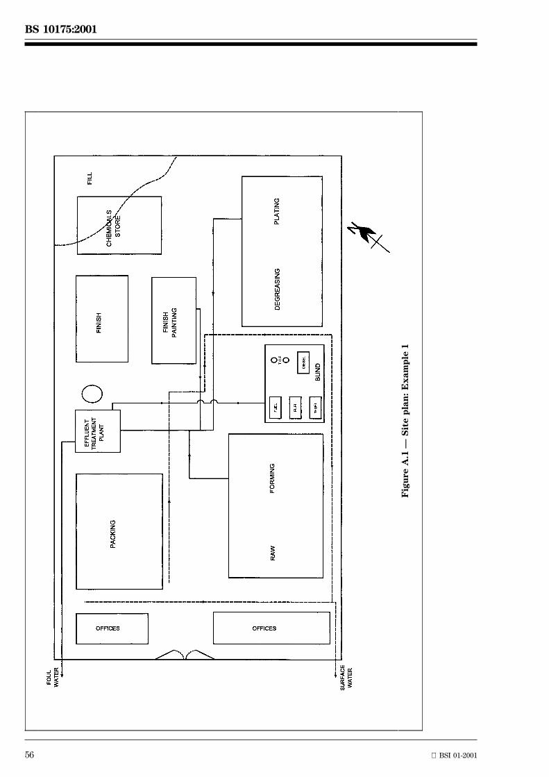
BS 10175:2001
56 BSI 01-2001
Fig
ure
A.1
ÐS
ite
pla
n:
Ex
am
ple
1

BSI 01-2001 57
BS 10175:2001
Previous geotechnical investigations have revealed the following sequence of strata at the site.
Depth Comments
0.0 m to 1.5 m Fill, including demolition waste.
1.5 m to 3.0 m Alluvial silty sands with varying proportions of gravel and clay in different areas of the site.
3.0 m to 6.0 m Glacial till, generally comprising stiff clay but with occasional sandy lenses.
6.0 m to >20 m Sandstone.
Groundwater occurs within the overlying alluvial sandy layer at a depth of 2.0 m to 2.5 m, and also within theunderlying sandstone bedrock at a piezometric head equal to 14 m below ground level. The sandstone isclassified as a major aquifer and several industrial abstraction licences are extant within 1 km of the site. Thegroundwater in the overlying alluvial sandy layer is classified as a minor aquifer with limited exploitationpotential. The site and adjacent areas are essentially flat and groundwater level measurements made during thegeotechnical investigations reveal a negligible groundwater gradient (and therefore flow) laterally across the sitein the overlying alluvial layer.
The initial conceptual model indicates the existence of the following potential sources of contamination:
Ð the storage areas for fuel, TCE and chemicals;
Ð the process areas where degreasing and plating have been carried out;
Ð the waste disposal area and the wastewater drains;
Ð the effluent treatment plant.
Contamination in these areas can also be expected due to local spillage and indiscriminate discharges. Theinitial conceptual model therefore defines discrete areas of local impact of the fill and alluvial sands by theidentified contaminants. The shallow groundwater is also expected to be affected, particularly locally to thesumps and drains and the process area. There could be areas of floating product as well as a variable verticalprofile of contamination in the shallow groundwater, due to the relative densities and solubilities of the differentpotential contaminants on the site. There could also be volatile organic compounds (VOCs), methane and carbondioxide in the fill and sand above the groundwater level.
The water receptors identified in the initial conceptual model for the existing (derelict) site condition, and forthe redeveloped site, are the shallow groundwater in the alluvial sands and the major aquifer in the sandstone.
There are no streams crossing or adjacent to the site, and the site is currently enclosed by secure fencing.Present adjacent land uses are commercial (warehousing), a major road and gardens of private houses on oneside. Therefore human receptors in the initial conceptual model for the existing condition are limited to personsoff-site, notably residents of the adjacent houses, pedestrians on the road pavement, and employees at thecommercial premises. The initial conceptual model for the redeveloped site additionally has either employees,customers and maintenance workers at the supermarket, or residents and visitors to the private housing, ashuman receptors. During the construction phase, both construction workers (in particular ground workers) andsite neighbours will be the human receptor groups.
There will be a direct pollutant linkage between ground contamination and the groundwater in the alluvial sands.However, the stiff clay layer is expected to provide a barrier to downward migration of contaminants, althoughpathways to the sandstone could exist due to sandy lenses in the glacial till and deep foundations. There istherefore the possibility of the deeper aquifer having been affected by the migration of contamination.
The proposal for redevelopment requires consideration of the potential for new migration routes to be formed.The removal of the existing hard landscape could result in exposure of workers during redevelopment, futureusers and occupiers and new buildings and structures. These possibilities will need to be addressed in theensuing site investigation.
A.2.4 Design and planning of field investigations (see clauses 7 and 8)
A.2.4.1 General
For a complex site of this size and nature, and with such a high potential level of contamination, a phasedinvestigation approach is essential. The number of phases and their scope is likely to depend on a combinationof technical and operational issues (such as access, planning permission, ownership, financing, etc.)
58 BSI 01-2001
BS 10175:2001
A.2.4.2 Option 1: supermarket
The first phase of intrusive investigation (the exploratory investigation) (see 5.4 and 5.7) is expected to besufficient to test the conceptual model of contamination and to provide enough information to assess the generalsuitability of the site for the proposed hard form of development (including indicative costs of remediation).
The conceptual model indicates the possibility of contamination associated with several identified localizedsources including electroplating chemicals (copper, nickel, zinc, cadmium, cyanide, chromic acid, acids andalkalis, etc.), solvent (TCE), fuel oil (diesel and heavy heating oil) and deposited waste. The contamination isassessed as likely to have impacted on the fill and alluvium, and the superficial groundwater above the glacial till.Due to the uncertainty of the permeability of the alluvium and the glacial till, deeper penetration (of the TCE inparticular), could be present. However, the possibility of migration of cyanides and metals also needs to beconsidered.
In terms of the proposed development with hard landscape, the areas of potential risk that require assessmentare:
Ð the possibility of VOCs (solvents and ground gases) affecting the development after construction;
Ð the possibility of chemicals (cyanides, chromates, metals, acids and alkalis), oil and solvents affectingworkers during construction;
Ð the possibility of acids affecting the concrete;
Ð the potential for contamination of the underlying aquifer.
The exploratory and subsequent main investigation (see 5.5 and 5.7) are consequently designed to produceinformation on these identified hazards so that the actual risk can be assessed and the need for remediationdetermined.
The proposed development envisages demolition and removal of buildings, hardstandings and foundations. Thereis a proposal to crush all demolition material and use this as hardcore for the new development. However, thiscreates several additional potential risks. If brickwork and concrete in the processing area has been penetratedby the various chemicals, hazards could be presented during the crushing process and also during the subsequentre-use of the crushed material. This aspect will also need to be addressed as a part of the investigation processbut is outside the scope of this illustration (see 7.4.1).
Since particular sources of potential contamination have been identified by the preliminary investigation, theexploratory investigation will comprise targeted sampling of the overlying fill, alluvial soils, shallow groundwaterand underlying groundwater at locations of potential contamination.
Boreholes are selected as the appropriate method of sample collection taking into account:
a) the presence of existing buildings;
b) the presence of extensive hard landscape;
c) the need for collection of perched water samples;
d) the need for collection of samples of groundwater from the underlying aquifer;
e) the desirability of checking the ground for the presence of methane, carbon dioxide and VOCs;
f) the nature and geology of the ground to be investigated.
Initial borehole locations are selected on a targeted basis (see 7.6.3 and 7.6.4). These are designed to investigatethe areas of oil storage (three boreholes), TCE storage (two boreholes), TCE usage (only one borehole ispossible due to access restrictions), the effluent treatment area (two boreholes) and the area of waste deposit(two boreholes).
Where the boreholes penetrate the glacial till they are formed with a bentonite plug at the base of the alluvium.Drilling is continued with a smaller diameter hole inside the original casing in order to minimize the possibility offorming contaminant migration routes.
Additional non-targeted boreholes are considered necessary to obtain a more general assessment of the site andto ascertain how the actual contamination correlates with the conceptual model. A further 18 boreholes arepostulated on the basis of a 50 m centre grid. However, some of these locations are not accessible due to existingbuildings and potentially live services. Some of the inaccessible locations can be accommodated by relocation bya few metres (from the original point), providing effective sampling in relation to the grid. As a consequence ofthe postulated 18 boreholes, only 14 are actually installed.
Thus the exploratory investigation comprises 10 boreholes, located for targeted judgmental sampling, and afurther 14, located on an approximate 50 m centre grid. Samples are collected at 0.5 m depth intervalsbetween 0.5 m below existing ground and 1 m into the glacial till. It is anticipated that from that point to the baseof the boreholes, samples will be collected at 1 m depth intervals. The on-site environmental scientist is giveninstructions to take additional samples as necessary on the basis of any on-site observations.
BSI 01-2001 59
BS 10175:2001
During borehole formation, atmospheres are monitored at 1.0 m intervals for methane, carbon dioxide andoxygen deficiency and also with a PID monitor with an 11.7 ev lamp (chosen to include sensitivity to chlorinatedsolvents). Pre-weighed sample containers (including some with solvent specifically for TCE collection) are used.Sampling and analysis of at least five solid samples at each location plus analysis of groundwater will providedata on the anticipated localized sources of contamination and also on the general nature of contaminationacross the site.
On this spacing, significant areas of contamination (up to 2 500 m2) could be missed. However, this is consideredacceptable within the remit of the exploratory investigation.
The information from this exploratory investigation is used to:
a) substantiate the conceptual model of contaminant distribution formulated after the preliminaryinvestigation (desk study);
b) assess the viability of the proposed development;
c) identify areas of the site that require more detailed investigation:
i) for delineation of areas of high or specific contamination;
ii) for provision of information for a risk assessment;
iii) for the formulation of a suitable remediation strategy.
The results from the exploratory investigation show there is significant localized contamination of the overlyingground and the shallow groundwater aquifer, in particular around the fuel storage tanks, in the area of TCEusage and in the electroplating area. The exploratory investigation did not, however, detect contamination of thedeeper aquifer, nor was any contamination of the shallow groundwater detected at the area of TCE storage.Elsewhere across the site there were locally elevated levels of heavy metals and hydrocarbons in soils, but notgenerally significantly above generic screening levels for hard forms of development.
On the basis of the findings of the exploratory investigation it is determined that a further main investigation isrequired to provide more detailed information on the site for the risk assessment and remediation works,including delineation of contamination hotspots and plumes.
The main investigation (see 5.5 and 5.7) is carried out when the whole site becomes available, after demolitionof the buildings but before removal of the hard landscape.
The main investigation involves:
Ð an additional 16 sample locations (boreholes) radiating from the fuel storage tanks (with provision for fourfurther sampling locations if a plume of contamination is indicated);
Ð an additional 16 sample locations (boreholes) around the area of TCE usage with provision for four furthersample locations if a plume is indicated.
[The exploratory investigation did not detect groundwater contamination in the deeper aquifer and so at each ofthese locations, the four outermost boreholes (of the 16) are formed into the underlying aquifer to confirmabsence of contamination.]
The electroplating area is subject to more specific examination and the drains running to the effluent treatmentplant are also targeted.
At the location of the TCE storage there was no indication of ground or groundwater contamination and so onlyan additional two boreholes are considered necessary to confirm the absence of TCE contamination at thislocation (see 7.6.3 and 7.6.4).
Taking into account the 14 sample locations already installed on the 50 m grid, the main investigation entails afurther 50 sample locations providing a 25 m grid. These can all now be accurately located on the 25 m gridpattern by breaking through the concrete hardstanding. In addition a further nine trial pits are undertaken toprovide a more detailed investigation of the electroplating area and the waste deposit area.
It is possible to carry out the targeted sampling of the drain runs using locations that coincide with the 25 m grid.
However, at grid points around the three locations where contamination of shallow groundwater was identifiedby the exploratory investigation, monitoring wells are formed within boreholes. Boreholes are also positionedupstream of, and at the downstream boundaries adjacent to, these locations so that a model of the groundwatercontamination can be formulated.
With the exceptions of the locations indicated, sampling is carried out by use of trial pits. Where contaminatedshallow groundwater was identified, additional trial pits are formed 15 m from the original sampling location, tohelp locate the source of the contamination. Provision is also made, during backfilling, to prevent excessiverainwater penetration of the hardstanding. This minimizes contamination migration before remediation begins.
60 BSI 01-2001
BS 10175:2001
Samples are collected at the same depths, and follow the strategy used in the exploratory investigation. As withthe exploratory investigation, at least five solid samples plus samples of groundwater are analysed for eachlocation. This analytical requirement is necessary to obtain sufficient data to be able to carry out the riskassessment with a satisfactory degree of confidence.
A.2.4.3 Option 2: housing with gardens
Investigation requirements for a housing redevelopment are more extensive than for a hard form of commercialdevelopment because of the higher potential health risks to human receptors on the redeveloped site. Thesehigher risks arise from more direct contaminant-pathway-receptor linkages in garden areas, greater exposuretimes, and more sensitive receptor groups (e.g. children).
The potential for VOCs to have an impact on a housing development through ingress into the buildings will beregarded as of greater significance and therefore lower acceptable concentration thresholds will be applied. Also,the potential for chemicals to be present in garden areas requires thorough investigation and assessment. With ahousing development, there will also be a greater impact due to increased infiltration of rainwater. This couldadversely affect contamination migration, particularly on the shallow aquifer. Commercial and public perceptionissues may also affect the intensity of investigation and remediation undertaken on housing redevelopment sites.
For the exploratory investigation (see 5.4 and 5.7) similar procedures to those used for Option 1 are followed.However, because there is a need to define the contamination status with a greater degree of confidence at anearlier stage, a greater intensity of sampling and testing is carried out.
The targeted sampling is not greatly increased. However, the non-targeted sampling is carried out on the basis ofa grid at 25 m centres (rather than 50 m for Option 1), with the proviso that within building footprints this eitherwill not be practicable, or will involve the use of specialist equipment for sampling (for example, low headroomboreholing equipment, or sampling with portable equipment through pre-cored holes).
Because of the increased number of sample locations and the associated cost and the relative importance of theoverlying layer to future human receptors, a greater proportion of the sampling points are trial pits, in place ofsome of the boreholes. However, the siting of the trial pits has to consider the costs of breaking out concretehardstanding and reinstatement of trial pit locations to ensure that the locations are satisfactorily sealed toprevent the formation of migration routes (due to rainwater infiltration). It is also necessary to reinstate the areato enable large articulated wagons to drive over the locations if parts of the site are still in use.
For the main investigation (see 5.5 and 5.7) the targeted examination in the ªhot spotº areas is carried out asalready described, though additional non-targeted sampling points are required due to the need for greaterconfidence in the risk assessment findings.
Assuming a proposed development layout has been drawn up, the main investigation includes sampling at amaximum of 10 m centres in the garden areas, particularly in the suspect areas of TCE storage, chemical storage,electroplating and waste disposal. Locations that could not be previously investigated due to the standingbuildings, are now included. This greater number of sample locations are investigated either by trial pits orwindow sampling. Samples are collected down to the top of the glacial till, unless there are indications of deepercontamination.
If the layout of the proposed development is not known, sampling and investigation of garden areas could becarried out as a supplementary investigation (see 5.6 and 5.7) when a plan becomes available.
A.3 EXAMPLE 2: Previously developed site
A.3.1 Objectives (see clause 4)
This site, adjacent to a major tidal river, is to be developed for leisure facilities, which will include public openspace, a sports hall and a boathouse. The site is approximately 90 m3 175 m (1.6 hectares) with a tidal riverfrontage at the southern end of the site of 90 m. A plan of the site is given in Figure A.2.
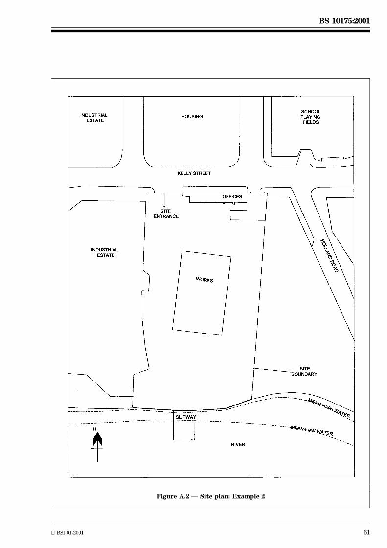
BSI 01-2001 61
BS 10175:2001
Figure A.2 Ð Site plan: Example 2
62 BSI 01-2001
BS 10175:2001
A.3.2 Strategy for the investigation (see clause 5)
The investigation will be undertaken in phases. The first phase will be the preliminary investigation (see 5.3and clause 6), comprising desk study, site reconnaissance, and formulation of the initial conceptual model andrisk assessment. The reconnaissance visit will be undertaken following the collection and review of readilyavailable information, and following initial enquiries to parties with site-specific information. During the sitereconnaissance visit, the reconnaissance team will be equipped to take surface samples of discoloured groundand of any waste piles for laboratory testing, and also to take water samples from ponds and adjacent streams.
It is very unlikely that the preliminary investigation will be sufficient to meet the investigation objectives, andan exploratory investigation (see 5.4 and 5.7) will be undertaken. The scope and methods of the exploratoryinvestigation will be established by the preliminary investigation. It will include soil and groundwater sampling,soil gas monitoring, and laboratory testing of soil and groundwater samples.
The exploratory investigation is unlikely to be sufficient to meet the objectives for redevelopment of the site anda main investigation (see 5.4 and 5.7) will be undertaken to collect all the outstanding information.
The requirements for the contamination investigations will be integrated with geotechnical investigations of thesite (although these geotechnical investigations are not discussed below).
A.3.3 Preliminary investigation (see clause 6)
The preliminary investigation identified the following historical information and initial conceptual model.
The site was apparently undeveloped up to 1935 with marshy ground shown on part of the site adjacent to theriver. Approximately 100 m to the north east of the site the 1925 map shows an area identified as workings.However, these workings are not marked on the 1954 map and the area is shown to be occupied by a school andplaying field. The 1954 map shows a large unidentified building, in the middle of the site with a slipway into theriver and some smaller (unidentified) buildings on the road frontage. The large building is subsequently identifiedas ªworksº but the latest map does not show this building. Local history references and anecdotal evidenceindicate that aircraft (seaplanes) were assembled in this area during the Second World War but it is not possibleto confirm this.
Most of the site away from the river is covered with concrete and tarmac in a poor state of repair. This groundcover is regarded as unlikely to be wholly impervious. Toward the river between the building and the slipway theground is well compacted with hardcore material.
Examination of geological information indicates the existence of alluvial deposits over River Terrace Gravelslying over at least 60 m of London Clay. Beneath the London Clay lies chalk with a deep saturated zone, which isclassed as a major aquifer. The groundwater in the terrace gravels is classified as a minor aquifer. There is thelikelihood of the marshy ground having been raised before development with imported fill, possibly at the sametime as the adjacent ground workings (1925 map) were infilled.
There is no specific data available for identifying strata thickness and estimates (based on British GeologicalSurvey Maps) indicate alluvium overlying a likely thickness of the terrace gravel strata of 3 m to 4 m and also thatthe London Clay could be located at approximately 5 m below ground level.
The initial conceptual model for the site indicates 1 m to 2 m of imported material used for raising the site to theexisting ground level. Given the possible date of development this could include ashy fill with associatedsporadic contamination. There is nothing to indicate the presence of any tanks or other features but, given thepossible previous use, it is considered that there could be contamination due to fuels and solvents both fromspillage and storage. Contamination from metalworking is also possible.
There is no information available on the nature of the alluvial material, which could be low permeabilitysilt (clay) or higher permeability material such as sandy material or peat. It is possible that mobile contaminantssuch as fuel and solvents could be retained by the alluvial layer or could have penetrated the underlying RiverTerrace Gravels. It is also likely that the water in the terrace gravels is in direct contact with the river and thatthe piezometric pressure in the gravels is similar to the mean river level. It is not known whether there isperched water in the made ground or if there is continuity with the gravels.
There is the possibility of significant concentrations of methane and carbon dioxide on the site. These gasescould derive either from the alluvial material present, or as a result of migration from the potential infilled areato the north-east. This potential presence of ground gas could present a hazard within buildings and undergroundservices of the proposed development.
There is the possibility of contamination associated with material used for raising the ground and also because ofprevious activities on site. This contamination could include metals and organics such as phenols, polyaromatichydrocarbons and in areas of former use, solvents. However, there is no indication of where such localizedcontamination could exist, other than around the area where the building existed.
BSI 01-2001 63
BS 10175:2001
Although there are existing areas of soft landscape toward the river, the redevelopment with public open spacewill increase the overall area where rainfall penetration could occur. This will increase the risk of contaminationmigration towards, and into, the river. The initial conceptual model indicates that there could be contaminatedperched water on the alluvium, but there is no evidence of continuity with the River Terrace Gravels, which arelikely to be connected to the river. The investigation therefore needs to provide information with which to assessthe possible impact of contamination migration on the perched water. It also needs to establish if there is anycontinuity between perched water and the underlying water in the terrace gravels.
Any contamination present within the site could present a hazard to workers during construction and users afterredevelopment. Certain contaminants could also affect the construction materials. It is necessary, therefore, tocarefully determine the nature and distribution of contamination and to identify any localized areas.
A.3.4 Sampling strategy
A.3.4.1 General
Due to the uncertainties in the available site information revealed by the preliminary investigation, it isessential to carry out the intrusive investigation in two stages. The limited exploratory investigation (see 5.4and 5.7) is designed to provide sufficient data that will focus the main investigation (see 5.5 and 5.7) on areasof potential concern and avoid unnecessary work.
A.3.4.2 Exploratory investigation
It is considered appropriate to use a mix of boreholes and trial pits, (though window sampling could be used inplace of the latter). It is thought better to ascertain the nature of the ground and obtain an indication of thelocation of the terrace gravels in the exploratory investigation to determine if window sampling will besuccessful. It is perceived that difficulties for window sampling, such as obstructions in the made ground andproblems in collecting samples from the gravels, could exist.
The boreholes are used to:
Ð determine the depth and thickness of strata to the top of the London Clay;
Ð obtain solid samples of made ground and alluvium;
Ð install gas monitoring wells and groundwater monitoring wells.
Construction of the boreholes is in two stages to minimize the potential for contamination pathways from madeground to the underlying gravels. The boreholes are formed until the alluvium is encountered and then a 1 m plugof cement/bentonite installed and allowed to set, before continuing to drill through the terrace gravels using asmaller diameter shell inside the casing in the original borehole (see 7.6.3.4 and 8.2.3.1). The final depth of theboreholes is 0.5 m into the London Clay, except if they are required to go to greater depth for geotechnicalpurposes.
During the formation of the boreholes, monitoring for ground gases allows an indication of the presence ofhazardous gases (notably methane and carbon dioxide) at different depths to be made (see 7.6.4). On completionof the boreholes, standpipes are installed to monitor and sample ground gases and groundwater quality andlevels.
The installation of gas standpipes in completed boreholes enables monitoring of ground gas composition, flowrate and pressure. The standpipes for gas monitoring wells extend through the full depth of the made ground andalluvium and are perforated from 1 m below ground level to the base.
Most of the groundwater monitoring wells are formed through the River Terrace Gravels down to 0.5 m into theunderlying clay, with a well screen extending at least 2 m to 3 m across the terrace gravel for the purposes ofsampling the minor aquifer (see 7.6.3). The response zone in the gravels is sealed off from the overlying madeground and perched water with a bentonite plug. Monitoring of water depth, in conjunction with tidal variationand river water height, provides information on the impact of tidal variation on the groundwater of the site andwhether there is evidence of continuity between the gravels and the river. Above the bentonite plug, at the levelof the alluvium, a combined gas monitoring and groundwater sampling well is in some cases installed in thesame borehole to enable gas monitoring of the strata above the alluvial layer.
One of these combined wells is installed in the north-east corner of the site to check for evidence of gasmigration from the suspected landfill. Three combined wells are placed centrally on the site at the northern end,in the middle and at the river end of the site.
Six trial pits are placed at 50 m centres across the site to sample the made ground down to the alluvium and, inconjunction with the boreholes, to check for the existence of perched water. The trial pits will enable collectionof solid samples of the made ground and the upper 0.5 m of the alluvium.
64 BSI 01-2001
BS 10175:2001
On the basis of this proposed strategy a significant area of contamination could be missed(up to approximately 2 500 m2 or 17.5 % of the area of the site). The conclusions from the exploratoryinvestigation are used to:
a) substantiate and enhance the conceptual model;
b) assess the viability of the proposed development;
c) identify aspects of the site that require more detailed examination to enable a risk assessment to be carriedout and suitable remediation strategies to be formulated.
The results of the exploratory investigation indicate that the alluvial layer is 1.5 m to 2.0 m thick towards theriver. At the northern (inland) end of the site, the alluvium was not encountered and only a thin layer of sandysilty material lies between the terrace gravels and the made ground.
Perched water was only encountered in the three trial pits and two boreholes nearest the river. This couldindicate that perched water flows away from the river until it percolates down into the terrace gravels where thealluvium thins. Water level monitoring indicates that the groundwater in the terrace gravels is affected by thetides and therefore is in direct continuity with the river. This effect was shown to occur 15 m into the site butwas not detected at a distance of 90 m from the river.
Made ground thickness varied between 2 m to 3 m and the terrace gravels were also 2 m to 3 m thick.Trichloroethylene (TCE) and ethylene glycol ethers (solvents) were detected in the groundwater in the terracegravels in the centre of the site but no free product was identified. Between the building and the slipway anelevated concentration (greater than 1 %) of mineral oil was identified but the investigation team did not recordany odours at this location. Methane and carbon dioxide were detected in the gravels at the north-eastern end ofthe site. Metals including lead, cadmium and zinc and elevated concentrations of arsenic and sulfate weredetected in the made ground towards the river.
As a result of this information the initial conceptual model is reviewed and due consideration indicates that inoverall terms it is correct, but that there is a need for greater detail. The information obtained during theexploratory investigation indicates the presence of ground gas contamination, contamination due to organiccompounds (solvents and mineral oil), elevated concentrations of metals, arsenic and sulfate and the possibilityof continuity between the perched groundwater on the alluvium and the underlying terrace gravels. Thisinformation requires elaboration by the main investigation (see 5.5 and 5.7) in order to provide adequateinformation on which to base the risk assessments.
The main investigation needs to be designed to assess gas migration onto the site because of the potential riskto users resulting from any gas build-up in buildings.
The presence of solvents and mineral oil requires further investigation because of the potential for impact onperched groundwater and, if continuity is established, upon the water in the terrace gravels and subsequently theriver. Solvent vapours could also build up within the building service ducts and both solvents and mineral oilcould affect the building structures and services.
The metals, arsenic and sulfate are of concern due to potential effects on vegetation, on-site users and on theenvironment resulting from wind-blown dust. Sulfates can also affect the concrete used in buildings and otherstructures.
The presence of the contaminants poses a potential hazard to workers during redevelopment and will requirecareful methods of working during redevelopment to prevent effects on the environment and adjacent areas dueto emissions or distribution of dust.
A.3.4.3 Main investigation
The next stage of investigation needs to address the potential contaminant-pathway-receptor relationshipsidentified. The investigation needs to examine the site to ensure that, if contamination is identified, it is notpresent at a concentration that will present a risk to future users of the site, construction workers, thegroundwater or river, vegetation, the proposed redevelopment or the environment generally (for examplewind-blown dust).
The main investigation (see 5.5 and 5.7) therefore has to be designed to produce additional information onthese specific aspects of the site and also to characterize, to a greater extent, the general nature of the madeground so that risk assessments with a satisfactory degree of confidence can be carried out.
The overall strategy for the main investigation will be based on a 25 m grid using a window sampler to collectsamples down to the alluvium and also a sample of the alluvium itself. Some locations will be sampled usingboreholes where these are suitably located for the installation of monitoring wells.
In addition, groundwater monitoring wells will be positioned along the boundary with the river to determinewater quality in this region (see 7.6.3).
BSI 01-2001 65
BS 10175:2001
Monitoring wells will also be formed at the northern end of the site to check groundwater quality and at somelocations will be duplicated with gas monitoring wells (see 7.6.4).
Two additional (targeted) boreholes will be installed at 25 m centres along the eastern boundary at the northernend of the site to provide further monitoring locations for ground gas migration.
In the centre of the site, four monitoring wells will be installed down to the London Clay to assess the extent oforganic contamination (by TCE and ethylene glycol ethers) and these will also be sampled and analysed toassess the overall groundwater quality. This is considered the most economic approach to the problem. However,it is sometimes necessary to carry out supplementary investigations if insufficient information on the distributionof organic contaminants in the groundwater is obtained.
Four further boreholes will be installed in the area of the building and the slipway to delineate and estimate thedegree of oil contamination. As with the investigation of the organic contamination it is accepted that moreboreholes could be required.
It is anticipated that all boreholes will be able to provide ongoing monitoring during the construction period.
Samples will be taken at 0.5 m depth intervals to the base of the sampling location or the alluvium (whichever isthe greater) and at 1.0 m intervals through the gravels, with a sample being taken 0.25 m into the clay where thisencountered. All the samples of made ground and two samples from the alluvium will be analysed. Initially twosamples from the gravel strata will be analysed with provision for the analysis of more samples if contaminationis detected. All groundwater samples will be analysed and at least one gas sample from each monitoring boreholewill be analysed to confirm on-site testing results. Provision will also be made for collection of boreholeatmosphere samples to determine the concentration of solvents present. This strategy should identifycontamination up to a minimum of 625 m3.
Groundwater sampling is scheduled to be carried out on three occasions after installation of the monitoringwells. The monitoring programme will also include determination of depth of groundwater and height of the riverat the same time.
Soil gas monitoring will be carried out over an extended time period including at least once when rapidreduction in atmospheric pressure occurs.
Annex B (informative)
Health and safety in site investigations
B.1 General
Health and safety is a very important aspect of any site investigation, since with contaminated sites there is avery real risk of either toxic effects on, or physical injuries to, workers. It is a legal requirement that workers areprotected from risks presented by the working environment, and the public and the environment also requireprotection. Reference should be made to the following documents:
Ð HS (G) 66 published by the Health and Safety Executive [24];
Ð R132 [25] which provides a thorough review of legislation and safe working practices;
Ð ISO/DIS 10381-3.
NOTE Attention is drawn to the application of the Construction (Design and Management) Regulations (CDM Regulations) [9], whichplace explicit duties on designers and contractors to plan, co-ordinate and arrange health and safety.
B.2 Safety policy
Any organization involved in site investigations and sampling should have a safety policy, which sets out therequirements for safe working. Adherence to the policy should be a part of the conditions of employment of allpersonnel. It should:
Ð emphasize the need for alertness and vigilance on the part of site personnel to protect themselves andothers from hazards during investigation and sampling;
Ð emphasize the need to follow standard operating procedures where these exist;
Ð prescribe the responsibilities of each member of the investigation team (including the responsibilities to anysub-contracted personnel and to the general public);
Ð include a mandatory ban on smoking, eating, or drinking whilst on site carrying out a sampling exercise orother site investigation;
Ð emphasize the need for checking for the presence of services at all sampling locations before commencingwork.
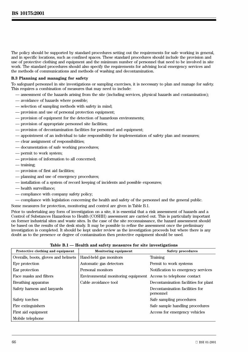
66 BSI 01-2001
BS 10175:2001
The policy should be supported by standard procedures setting out the requirements for safe working in general,and in specific locations, such as confined spaces. These standard procedures should include the provision anduse of protective clothing and equipment and the minimum number of personnel that need to be involved in sitework. The standard procedures should also specify the requirements for advising local emergency services andthe methods of communications and methods of washing and decontamination.
B.3 Planning and managing for safety
To safeguard personnel in site investigations or sampling exercises, it is necessary to plan and manage for safety.This requires a combination of measures that may need to include:
Ð assessment of the hazards arising from the site (including services, physical hazards and contamination);
Ð avoidance of hazards where possible;
Ð selection of sampling methods with safety in mind;
Ð provision and use of personal protection equipment;
Ð provision of equipment for the detection of hazardous environments;
Ð provision of appropriate personnel site facilities;
Ð provision of decontamination facilities for personnel and equipment;
Ð appointment of an individual to take responsibility for implementation of safety plan and measures;
Ð clear assignment of responsibilities;
Ð documentation of safe working procedures;
Ð permit to work system;
Ð provision of information to all concerned;
Ð training;
Ð provision of first aid facilities;
Ð planning and use of emergency procedures;
Ð installation of a system of record keeping of incidents and possible exposures;
Ð health surveillance;
Ð compliance with company safety policy;
Ð compliance with legislation concerning the health and safety of the personnel and the general public.
Some measures for protection, monitoring and control are given in Table B.1.
Prior to undertaking any form of investigation on a site, it is essential that a risk assessment of hazards and aControl of Substances Hazardous to Health (COSHH) assessment are carried out. This is particularly importanton former industrial sites and waste sites. In the case of the site reconnaissance, the hazard assessment shouldbe based on the results of the desk study. It may be possible to refine the assessment once the preliminaryinvestigation is completed. It should be kept under review as the investigation proceeds but where there is anydoubt as to the presence or degree of contamination then protective equipment should be used.
Table B.1 Ð Health and safety measures for site investigations
Protective clothing and equipment Monitoring equipment Safety procedures
Overalls, boots, gloves and helmets Hand-held gas monitors Training
Eye protection Automatic gas detectors Permit to work systems
Ear protection Personal monitors Notification to emergency services
Face masks and filters Environmental monitoring equipment Access to telephone contact
Breathing apparatus Cable avoidance tool Decontamination facilities for plant
Safety harness and lanyards Decontamination facilities forpersonnel
Safety torches Safe sampling procedures
Fire extinguishers Safe sample handling procedures
First aid equipment Access for emergency vehicles
Mobile telephone
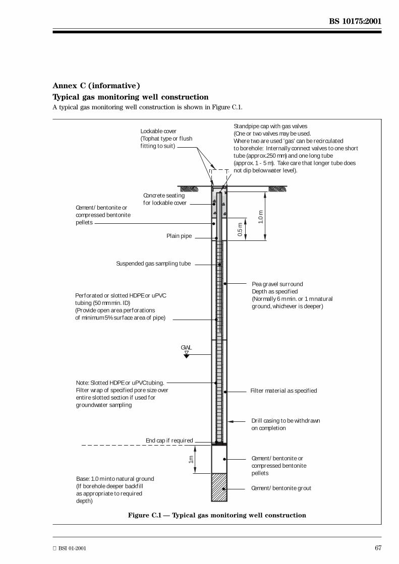
BSI 01-2001 67
BS 10175:2001
Annex C (informative)
Typical gas monitoring well constructionA typical gas monitoring well construction is shown in Figure C.1.
Lockable cover(Tophat type or flushfitting to suit)
Concrete seatingfor lockable cover
Cement/bentonite orcompressed bentonitepellets
Plain pipe
Suspended gas sampling tube
Perforated or slotted HDPE or uPVCtubing (50 mm min. ID)(Provide open area perforationsof minimum 5% surface area of pipe)
GWL
Note: Slotted HDPE or uPVC tubing.Filter wrap of specified pore size over entire slotted section if used for groundwater sampling
End cap if required
1m
Base: 1.0 m into natural ground(If borehole deeper backfillas appropriate to requireddepth)
Cement/bentonite orcompressed bentonitepellets
Cement/bentonite grout
Drill casing to be withdrawnon completion
Pea gravel surroundDepth as specified(Normally 6 m min. or 1 m naturalground, whichever is deeper)
0.5
m
1.0
m
Standpipe cap with gas valves(One or two valves may be used.Where two are used 'gas' can be recirculatedto borehole: Internally connect valves to one shorttube (approx.250 mm) and one long tube (approx. 1 - 5 m). Take care that longer tube does not dip below water level).
Filter material as specified
Figure C.1 Ð Typical gas monitoring well construction
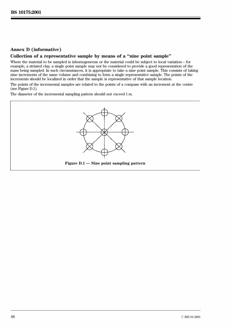
68 BSI 01-2001
BS 10175:2001
Annex D (informative)
Collection of a representative sample by means of a ªnine point sampleºWhere the material to be sampled is inhomogeneous or the material could be subject to local variation ± forexample, a striated clay, a single point sample may not be considered to provide a good representation of themass being sampled. In such circumstances, it is appropriate to take a nine point sample. This consists of takingnine increments of the same volume and combining to form a single representative sample. The points of theincrements should be localized in order that the sample is representative of that sample location.
The points of the incremental samples are related to the points of a compass with an increment at the centre(see Figure D.1).
The diameter of the incremental sampling pattern should not exceed 1 m.
Figure D.1 Ð Nine point sampling pattern
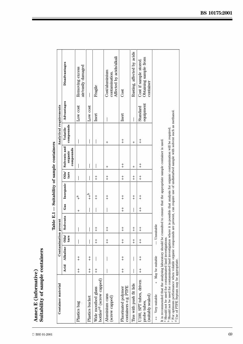
BS 10175:2001
BSI 01-2001 69
An
nex
E(i
nfo
rmati
ve)
Su
itabil
ity
of
sam
ple
con
tain
ers
Tab
leE
.1Ð
Su
itab
ilit
yo
fsa
mp
leco
nta
iners
Co
nta
iner
ma
teri
al
Co
nta
min
ati
on
pre
sen
tA
na
lyti
ca
lre
qu
irem
en
ts
Acid
Alk
ali
ne
Oil
s/ta
rsS
olv
en
tsG
as
Ino
rgan
icO
ils/
tars
So
lven
tsan
do
rga
nic
co
mp
ou
nd
s
Vo
lati
leco
mp
ou
nd
sA
dva
nta
ge
sD
isa
dva
nta
ge
s
Pla
stic
sb
ag+
++
+Ð
Ð+
+a
ÐÐ
ÐL
ow
cost
Rem
ovi
ng
exce
ssai
r/ea
sily
dam
aged
Pla
stic
sb
uck
et+
++
+Ð
ÐÐ
++
bÐ
ÐÐ
Lo
wco
stÐ
Wid
em
ou
thed
glas
sb
ott
lesc
d(s
crew
cap
ped
)+
+Ð
++
++
Ð+
++
+Ð
ÐIn
ert
Fra
gile
Alu
min
ium
can
s(s
crew
cap
ped
)Ð
Ð+
++
+Ð
++
++
++
ÐC
ost
/alu
min
ium
con
tam
inat
ion
.A
ffec
ted
by
acid
s/al
kal
i
Flu
ori
nat
edp
oly
mer
con
tain
ers
e.g.
PT
FE
++
++
++
++
++
++
++
++
++
Iner
tC
ost
Tin
sw
ith
pu
shfi
tli
ds
ÐÐ
++
++
Ð+
++
++
+Ð
Ru
stin
g,af
fect
edb
yac
ids
U10
0,S
PT
tub
es,
dri
ven
pro
be
tub
es,
(su
itab
lyse
aled
)
++
++
++
++
++
++
++
++
++
Sta
nd
ard
equ
ipm
ent
Co
stif
sam
ple
sto
red
.O
bta
inin
gsa
mp
lefr
om
con
tain
er
++
Very
suit
ab
le+
May
be
suit
ab
leÐ
Un
suit
ab
le
Itis
reco
mm
en
ded
that
the
an
aly
sin
gla
bo
rato
rysh
ou
ldb
eco
nsu
lted
toen
sure
that
the
ap
pro
pri
ate
sam
ple
co
nta
iner
isu
sed
.a
Sh
ou
ldn
ot
be
use
dfo
rco
nta
min
ate
dla
nd
invest
igati
on
s.b
Sh
ou
ldn
ot
be
use
dfo
rco
nta
min
ate
dla
nd
invest
igati
on
wh
ere
itis
po
ssib
leth
at
an
aly
sis
for
org
an
icco
nta
min
ati
on
wil
lb
ere
qu
ired
.c
Fo
ro
pti
mu
mp
erf
orm
an
ce
wh
en
vo
lati
leo
rgan
icco
mp
ou
nd
sare
pre
sen
t,can
requ
ire
use
of
un
dis
turb
ed
sam
ple
wit
hso
lven
tsu
ch
as
meth
an
ol.
dU
seo
fP
TF
ES
ep
tum
may
be
ap
pro
pri
ate
.

70 blank

BSI 01-2001 71
BS 10175:2001
Bibliography
Standards publications
DD ENV 13530:1999, Water quality Ð Guide to analytical quality control for water analysis.
ISO/DIS 5667-18, Water quality Ð Sampling Ð Part 18: Guidance on the sampling of groundwater ofcontaminated sites.
ISO/DIS 10381-1, Soil quality Ð Sampling Ð Part 1: Guidance on the design of sampling programmes.
ISO/DIS 10381-2, Soil quality Ð Sampling Ð Part 2: Guidance on sampling techniques.
ISO/DIS 10381-3, Soil quality Ð Sampling Ð Part 3: Guidance on safety.
ISO/DIS 10381-4, Soil quality Ð Sampling Ð Part 4: Guidance on the procedure for the investigation ofnatural, near natural and cultivated sites.
ISO/DIS 14507, Soil quality Ð Pretreatment of samples for the determination of organic contaminants.
ASTM E 1689-95, Standard guide for developing conceptual site models for contaminated sites.
Other publications
[1] GREAT BRITAIN. The Factories Act, 1961. London. The Stationery Office.
[2] GREAT BRITAIN. Offices, Shops and Railway Premises Act, 1963. London. The Stationery Office.
[3] GREAT BRITAIN. The Health and Safety at Work, etc. Act, 1974. London. The Stationery Office.
[4] GREAT BRITAIN. The Control of Pollution Act, 1974 and The Control of Pollution (Amendment) Act, 1989.London. The Stationery Office.
[5] GREAT BRITAIN. The Water Act, 1989. London. The Stationery Office.
[6] GREAT BRITAIN. The Environmental Protection Act, 1990. London. The Stationery Office.
[7] GREAT BRITAIN. The Water Resources Act, 1991. London. The Stationery Office.
[8] GREAT BRITAIN. The Environment Act, 1995, London. The Stationery Office.
[9] GREAT BRITAIN. The Construction Design and Management Regulations. 1995. London. The StationeryOffice.
[10] GREAT BRITAIN. Control of Substances Hazardous to Health Regulations, 1988. London. The StationeryOffice.
[11] CIRIA. Remedial treatment for contaminated land Ð Volume III: Site investigation and assessment.(SP103). 1995. (ISBN 0 860 17398 4).
[12] DETR/Environment Agency. Draft Handbook of model procedures for the management of contaminatedland.
[13] UNITED STATES ENVIRONMENTAL PROTECTION AGENCY. Guidance for the Data Quality ObjectivesProcess. US EPA. Washington DC (QA/G-4).
[14] THE ROYAL INSTITUTION OF CHARTERED SURVEYORS. Land Contamination Guidance for CharteredSurveyors. 1995.
[15] AMERICAN SOCIETY FOR TESTING AND MATERIALS. Standard Practice for Environmental SiteAssessments: Phase 1: Environmental Site Assessment Process, 1995. (E1527-93).
[16] RPS Group. Documentary research on industrial sites. (CLR 3). DETR. 1994. London. The StationeryOffice.
[17] DETR. Industry Profiles, see further reading.
[18] INTERDEPARTMENTAL COMMITTEE ON THE REDEVELOPMENT OF CONTAMINATED LAND.Guidance Notes. DETR.
[19] HIGHWAYS AGENCY. Site Investigation for Highway Works on Contaminated Land. Appendix A of theAdvice Note in Design Manual for Roads and Bridges. 1995. London. (HA 73/95).
[20] BRITISH GEOLOGICAL SURVEY. Applied Geological Maps for Planning and Development. A Review ofExamples from England and Wales 1983 to 1996. QJEG S1 to S44. Published as a supplement to Quarterlyjournal of engineering geology. (Also published by DETR as Environmental geology information for planningpurposes.)
[21] APPLIED ENVIRONMENTAL RESEARCH CENTRE LTD. Guidance on Preliminary Site Investigation ofContaminated Land. (CLR 2). DETR. 1994. London. The Stationery Office.
[22] ENVIRONMENTAL INDUSTRIES COMMISSION in association with the LABORATORY OF THEGOVERNMENT CHEMIST. 1997. A Quality Approach for Contaminated Land Consultancy. (CLR 12).DETR. 1997. London. The Stationery Office.

BS 10175:2001
72 BSI 01-2001
[23] ASSOCIATION OF GEOTECHNICAL AND GEOENVIRONMENTAL SPECIALISTS. Good Practice in SiteInvestigations.
[24] HEALTH AND SAFETY EXECUTIVE. Protection of workers and the general public during thedevelopment of contaminated land. [HS(G)66].
[25] CIRIA. A guide for safe working on contaminated sites. (R132). (ISBN 0 860 17451 4).
[26] GREAT BRITAIN. Environmental Protection (Duty of Care) Regulations 1991.
[27] GREAT BRITAIN. Special Waste Amendment Regulations 1996, (SI 1996 No. 2019). London.
[28] DETR. Sampling strategies for contaminated land. Report by The Centre for Research into the BuiltEnvironment. The Nottingham Trent University. (CLR 4). 1994. London. The Stationery Office.
[29] FLEMING, G. Recycling derelict land. Thomas Telford. London. 1992. (ISBN 0 727 71318 3).
[30] CIRIA. The measurement of methane and other gases from the ground. (R131). (ISBN 0 860 17372 0).
[31] CIRIA. Methane investigation strategies. (R150). (ISBN 0 860 17435 2).
[32] DETR. Landfill Gas. Waste Management Paper No. 27. 1991. London. The Stationery Office.(ISBN 0 117 52488 3).
[33] ENVIRONMENT AGENCY. Methods for the Examination of Water and Associated Materials. StandingCommittee of Analysts.
[34] MAFF. Methods of analysis. London. The Stationery Office.
[35] THE HEALTH AND SAFETY EXECUTIVE. Methods for the determination of hazardous substances.London. The Stationery Office.
[36] THE BUILDING RESEARCH ESTABLISHMENT. Sulfate and acid resistance of concrete in the ground.Digest 363. 1996.
[37] ENVIRONMENT AGENCY. Leaching tests for assessment of contaminated land. NRA Interim GuidanceR & D Note 301.
[38] UNITED STATES ENVIRONMENTAL PROTECTION AGENCY. Volatiles and semi volatiles. Solid WasteEPA 8240, 8260. Halogenated and Aromatic Volatile Organics, EPA 8270. Semi volatiles US-EPA EnvironmentalMonitoring Systems Laboratory, Las Vegas. Waste Water Analysis: EPA 624 Purgeable Hydrocarbons.EPA 625 Acids (Phenols), Base/Neutrals. US EPA Environmental Monitoring Systems Laboratory, Cincinnati,Ohio.
[39] MARSLAND, P. A. and CAREY, M. A. 1999. Methodology for the derivation of remedial targets for soil andgroundwater to protect water resources. Environment Agency R & D Publication 20.
[40] ENVIRONMENT AGENCY. 1999. Guidance on monitoring of landfill leachate, groundwater and surfacewater.
[41] GREAT BRITAIN. The Town and Country Planning Act, 1968. London. The Stationery Office.
[42] GREAT BRITAIN. The Building Control Act. (Various).
[43] AMERICAN SOCIETY FOR TESTING AND MATERIALS. Standard Guide for Developing Conceptual SiteModels for Contaminated Sites. 2000. (E1689-95).
[44] GREAT BRITAIN. Integrated Pollution Prevention and Control Act, 1999. London. The Stationery Office.
[45] SITE INVESTIGATION STEERING GROUP. Site investigation in construction 4: Guidelines for the safeinvestigation by drilling of landfills and contaminated land. Thomas Telford. London. 1993.
[46] CIRIA. Remedial treatment for contaminated land Ð Volume II: Decommissioning, decontamination anddemolition. (SP 102). (ISBN 0 860 17397 6).
[47] POLLARD, S. and GUY, J. 2001. Risk assessment for environmental professionals. The Chartered Instituteof Water and Environmental Management (CIWEM).
BSI 01-2001 73
BS 10175:2001
Further reading: publications on contaminated land
The following bodies regularly publish information on the assessment of contaminated land.
AEA
Environmental Technology Centre. AEA Technology plc, F6, Culham, Abingdon, Oxon, OX14 3EDB(Tel: 01235 463 162)
Building Research Establishment
For BRE publications contact, CRC Ltd., 51 Rosebery Avenue, London EC1R 4GB. Tel 020 7505 6622.
The following publications are of particular relevance.
PAUL. V. Bibliography of Case Studies on Contaminated Land: investigation, remediation andredevelopment. BRE Report BR 291. 1995. (ISBN 1 860 81032 2)
PAUL V. Performance of building materials in contaminated land. BRE Report BR 255. 1991.(ISBN 0 851 25624 4)
Construction of new buildings on gas-contaminated land, 1991. BRE Report BR 212. (ISBN 0 851 25513 2).
CROWHURST D. and P. F. BEEVER. Fire and Explosion Hazards Associated with the Redevelopment ofContaminated Land. Fire Research Station. BRE Information Paper IP2/87. 1987
Construction Industry Research and Information Association
6 Storey's Gate, Westminster, London SW1P 3AU.
Tel 020 7222 8891. http://ciria.org.uk.
In addition to publications [11], [25], [30] and [31] listed in the bibliography, the following publications are ofparticular relevance.
SP 101 Ð SP 111 Remedial treatment for contaminated land.Vol I: Introduction and guide 1995. ISBN 0 860 17396 8.Vol II: Decommissioning, decontamination and demolition 1995. ISBN 0 860 17397 6.Vol III: Site investigation and assessment 1995. ISBN 0 860 17398 4.Vol IV: Classification and selection of remedial methods 1995. ISBN 0 860 17399 2.Vol V: Excavation and disposal 1995. ISBN 0 860 17400 X.Vol VI: Containment and hydraulic measures 1995. ISBN 0 860 17401 8.Vol VII: Ex-situ remedial methods for soils, sludges and sediments 1995. ISBN 0 860 17402 6.Vol VIII: Ex-situ remedial methods for contaminated groundwater and other liquids 1995.ISBN 0 860 17403 4.Vol IX: In-situ methods of remediation 1995. ISBN 0 860 17404 2.Vol X: Special situations 1995. ISBN 0 860 17405 0. E52.50.Vol XI: Planning and management 1995. ISBN 0 860 17406 9.Vol XII Policy and legislation 1996. ISBN 0 860 17407 7.
R130 Methane: Its occurrence and hazards in construction. ISBN 0 860 17373 9.R149 Protecting development from methane 1995. ISBN 0 860 17410 7.R152 Risk assessment for methane and other gases from the ground 1995. ISBN 0 860 17434 4.
Health and Safety Executive
Publications available from Health and Safety Executive Bookshop, PO Box 1999, Sudbury, Suffolk, CO10 6FS.Tel: 01787 881 165.
In addition to publication [24] in the bibliography, the following publication is of particular relevance.
Remediation of Contaminated Land: Occupational hygiene aspects on the safe selection and use of new soilclean up techniques. SIR5I, free publication.
Government Agencies
DETR
2nd floor, Ashdown House, London SW1E 6DE.
Tel: 020 7890 3000. http://www.detr.gov.uk.
Publications Sales Centre, Unit 21, Goldthorpe Industrial Estate, Goldthorpe, Rotherham, S63 9BL.
Tel. 01709 891318.
BS 10175:2001
74 BSI 01-2001
Environment Agency
Rivers House, Waterside Drive, Aztec West, Bristol, BS12 4UD.
Tel: 01454 624 411.
The Stationery Office Ltd Publications Centre
PO Box 276, London SW8 5DT.
Tel: 0870 600 5522.
The following documents contain relevant background information and guidance.
ICRCL (Inter-Departmental Committee on the Redevelopment of Contaminated Land Publications):
ICRCL 59/83 Guidance on the assessment and redevelopment of contaminated land. 2nd Ed, July 1987.
ICRCL 17/78 Notes on the development and after-use of landfill sites. 8th Ed, December 1990.
ICRCL 18/79 Notes on the redevelopment of gasworks sites, 5th Ed, April 1986.
ICRCL 23/79 Notes on the redevelopment of sewage works and farms. 2nd Ed, November 1983.
ICRCL 42/80 Notes on the redevelopment of scrap yards and similar sites. 2nd October 1983.
ICRCL 61/84 Notes on the fire hazards of contaminated land. 2nd Ed, July 1986.
ICRCL 64/85 Asbestos on contaminated sites. 2nd Ed, October 1990.
ICRCL 70/90 Notes on the restoration and aftercare of metalliferous mining sites for pasture and grazing.1st Ed, February 1990.
Contaminated Land Research Reports
In addition to the publications [16], [21], [22] and [28] listed in the bibliography from this series, the followingpublications are of relevance.
CLR 1 A framework for assessing the impact of contaminated land on groundwater and surfacewater. Reportby Aspinwall & Co. Volumes 1 & 2. 1994.
CLR 5 Information systems for land contamination. Report by Meta Generics Ltd., 1993.
CLR 6 Prioritisation & categorization procedure for sites which may be contaminated. Report byM J Carter Associates/DoE. 1995.
Industry profiles
Industry Profiles provide developers, local authorities and anyone else interested in contaminated land, withinformation on the processes, materials and castes associated with individual industries. They also provideinformation on the contamination which might be associated with specific industries, factors that affect thelikely presence of contamination, the effect of mobility of contaminants and guidance on potentialcontaminants. They are not definitive studies but introduce some of the technical considerations that need tobe in mind at the start of an investigation for possible contamination.
Airports. (ISBN 1 851 12289)
Animal and animal products processing works. (ISBN 1 851 12238 9)
Asbestos manufacturing works. (ISBN 1 851 12231 1)
Ceramics, cement and asphalt manufacturing works. (ISBN 1 851 12290 7)
Chemical works: coatings (paints and printing inks) manufacturing works. (ISBN 1 851 12291 5)
Chemical works: cosmetics and toiletries manufacturing works. (ISBN 1 851 12292 3)
Chemical works: disinfectants manufacturing works. (ISBN 1 851 12293 1)
Chemical works: explosives, propellants and pyrotechnics manufacturing works. (ISBN 1 851 12237 0)
Chemical works: fertilizer manufacturing works. (ISBN 1 851 12289 3)
Chemical works: fine chemicals manufacturing works. (ISBN 1 851 12234 5)
Chemical works: inorganic chemicals manufacturing works. (ISBN 1 851 12295 8)
Chemical works: linoleum, vinyl and bitumen-based floor covering manufacturing works.(ISBN 1 851 17296 6)
Chemical works: mastics, sealants, adhesives and roofing manufacturing works. (ISBN 1 851 12296 6)
Chemical works: organic chemicals manufacturing works. (ISBN 1 851 12275 3)
Chemical works: pesticides manufacturing works. (ISBN 1 851 12274 5)
Chemical works: pharmaceuticals manufacturing works. (ISBN 1 851 19236 2). E10
BSI 01-2001 75
BS 10175:2001
Chemical works: rubber processing works (including works manufacturing tyres or other rubber products).(ISBN 1 851 12234 6)
Chemical works: soap and detergent manufacturing works. (ISBN 1 851 12276 l)
Dockyards and dockland. (ISBN 1 851 12298 2)
Engineering works: aircraft manufacturing works. (ISBN 1 851 12299 0)
Engineering works: electrical and electronic equipment manufacturing works (including worksmanufacturing equipment containing PCBs). (ISBN 1 851 12300 8)
Engineering works: mechanical engineering and ordnance works. (ISBN 1 851 12233 8)
Engineering works: railway engineering works. (ISBN 1 851 12254 0)
Engineering works: shipbuilding, repair and shipbreaking (including naval shipyards).(ISBN 1 851 12277 X)
Engineering works: vehicle manufacturing works. (ISBN 1 851 12301 6)
Gasworks, coke works and other coal carbonisation plants. (ISBN 1 851 12232 X)
Metal manufacturing, refining and finishing works: electroplating and other metal finishing works.(ISBN 1 851 12278 8)
Metal manufacturing, refining and finishing works: iron and steelworks. (ISBN 1 851 12280 X)
Metal manufacturing, refining and finishing works: lead works. (ISBN 1 851 12230 3)
Metal manufacturing, refining and finishing works: non-ferrous metal works (excluding lead works).(ISBN 1 851 1232 4)
Metal manufacturing, refining and finishing works: precious metal recovery works. (ISBN 1 851 12279 6)
Oil refineries and bulk storage of crude oil and petroleum products. (ISBN 1 851 12303 2)
Power stations (excluding nuclear power stations). (ISBN 851 12281 8)
Pulp and paper manufacturing works. (ISBN 1 851 12304 0)
Railway land. (ISBN 1 851 12253 2)
Road vehicle fuelling, service and repair: garages and filling stations. (ISBN 1 851 12305 9)
Road vehicle fuelling, service and repair: transport and haulage centres. (ISBN 1 851 12306 7)
Sewage works and sewage farms. (ISBN 1 851 12282 6)
Textile works and dye works. (ISBN 1 851 12307 5)
Timber products manufacturing works. (ISBN 1 851 12308 3)
Timber treatment works. (ISBN 1 851 12283 4)
Waste recycling, treatment and disposal sites: drum and tank cleaning and recycling plants.(ISBN 1 851 12309 l)
Waste recycling, treatment and disposal sites: hazardous waste treatment plants. (ISBN 1 851 12310 5)
Waste recycling, treatment and disposal sites: landfills and other waste treatment or waste disposal sites.(ISBN 1 851 12311 3)
Waste recycling, treatment and disposal sites: metal recycling sites. (ISBN 1 851 12229 X)
Waste recycling, treatment and disposal sites: solvent recovery works. (ISBN 1 851 12312 1)
Profile of miscellaneous industries, (ISBN 1 851 12313 X) incorporating:
Charcoal works
Dry-cleaners
Fibreglass and fibreglass resins manufacturing works
Glass manufacturing works
Photographic processing industry
Printing and bookbinding works.

BS 10175:2001
BSI389 Chiswick High RoadLondonW4 4AL
|||||||||||||||||||||||||||||||||||||||||||||||||||||||||||||||||||||||||||||||||||||||||||||||||||||||||||||||||||||||||||||||
BSI Ð British Standards Institution
BSI is the independent national body responsible for preparing British Standards. Itpresents the UK view on standards in Europe and at the international level. It isincorporated by Royal Charter.
Revisions
British Standards are updated by amendment or revision. Users of British Standardsshould make sure that they possess the latest amendments or editions.
It is the constant aim of BSI to improve the quality of our products and services. Wewould be grateful if anyone finding an inaccuracy or ambiguity while using thisBritish Standard would inform the Secretary of the technical committee responsible,the identity of which can be found on the inside front cover. Tel: 020 8996 9000.Fax: 020 8996 7400.
BSI offers members an individual updating service called PLUS which ensures thatsubscribers automatically receive the latest editions of standards.
Buying standards
Orders for all BSI, international and foreign standards publications should beaddressed to Customer Services. Tel: 020 8996 9001. Fax: 020 8996 7001. Standardsare also available from the BSI website at http://www.bsi-global.com.
In response to orders for international standards, it is BSI policy to supply the BSIimplementation of those that have been published as British Standards, unlessotherwise requested.
Information on standards
BSI provides a wide range of information on national, European and internationalstandards through its Library and its Technical Help to Exporters Service. VariousBSI electronic information services are also available which give details on all itsproducts and services. Contact the Information Centre. Tel: 020 8996 7111.Fax: 020 8996 7048.
Subscribing members of BSI are kept up to date with standards developments andreceive substantial discounts on the purchase price of standards. For details ofthese and other benefits contact Membership Administration. Tel: 020 8996 7002.Fax: 020 8996 7001. Further information about BSI is available on the BSI website athttp://www.bsi-global.com.
Copyright
Copyright subsists in all BSI publications. BSI also holds the copyright, in the UK, ofthe publications of the international standardization bodies. Except as permittedunder the Copyright, Designs and Patents Act 1988 no extract may be reproduced,stored in a retrieval system or transmitted in any form or by any means ± electronic,photocopying, recording or otherwise ± without prior written permission from BSI.
This does not preclude the free use, in the course of implementing the standard, ofnecessary details such as symbols, and size, type or grade designations. If thesedetails are to be used for any other purpose than implementation then the priorwritten permission of BSI must be obtained.
If permission is granted, the terms may include royalty payments or a licensingagreement. Details and advice can be obtained from the Copyright Manager.Tel: 020 8996 7070.