bruker sample transport - chemistry scope of this manual ... the bruker sample transport system...
TRANSCRIPT
Version
think forward
Bruker BioSpin
Bruker Sample Transport
002
NMR Spectroscopy
BSTInstallation and Technical Manual
This manual was written by
Bruker BioSpin AG
© November 21, 2008: Bruker Biospin AG
Fällanden, Switzerland
P/N: Z31123DWG-Nr.: 799002 - 002
For further technical assistance on the Bruker Sample Transportunit, please do not hesitate to contact your nearest BRUKER dealer or contact us directly at:
Bruker BioSpin AG Industriestrasse 26 CH - 8117 Fällanden Switzerland Phone: + 41 44 825 9111 FAX: + 41 44 825 9696 E-mail: [email protected] Internet: www.bruker.com
Copyright © by Bruker BioSpin NMR GmbH
All rights reserved. No part of this publication may be reproduced, stored in a retrieval system, or transmitted, in any form, or by any means without the prior consent of the publisher. Product names used are trademarks or registered trademarks of their respective holders.
Contents
Contents ............................................................................ 3
1 Introduction ........................................................................ 51.1 Introduction ........................................................................................ 51.2 Scope of this Manual .......................................................................... 51.3 Contact for Technical Assistance ........................................................ 6
2 Configurations ................................................................... 7
3 Setup .................................................................................. 93.1 General Setup Instructions ................................................................. 93.2 Installation of the Upgrade Kit ............................................................. 93.3 Connecting to the BSMS ................................................................... 103.4 Connecting to the B-SN 18 ............................................................... 103.5 Setup with a Sample Changer ........................................................... 10
4 Operation ...........................................................................114.1 Basic Version ................................................................................... 114.2 Upgraded Version ............................................................................. 11
Mode 1 ......................................................................................... 11Mode 2 ......................................................................................... 11Mode 3 .........................................................................................12
5 Appendix .......................................................................... 155.1 Basic Version ................................................................................... 165.2 Upgrade Kit ...................................................................................... 175.3 Setup for Mode 1 .............................................................................. 185.4 Setup for Mode 2 .............................................................................. 195.5 Setup for Mode 3 .............................................................................. 205.6 Operating Matrix ............................................................................... 215.7 Configuration with B-SN 18 ............................................................... 225.8 Configuration with Sample Changer .................................................. 235.9 Setup for Sample Changer with Upgrade Kit Installed ....................... 245.10 Electrical Wiring Diagram ................................................................. 255.11 Specifications Table .......................................................................... 26
Figures ............................................................................ 27
Installation and Technical Manual Version 002BRUKER BIOSPIN 3

Contents
4 BRUKER BIOSPIN Installation and Technical Manual Version 002
1Introduction 1
Introduction 1.1
The Bruker Sample Transport System (BST) servers a number of purposes:
• It provides a safe and quiet transport of the sample to the probe.
• It measures the spinning rate.
• It provides position information of the sample.
• It manages the lift, spinning, and tempering gas flows to and from the spinner/probe.
The BST is a versatile piece of equipment. It can be configured and operated in a number of ways, matching exactly the experiment‘s needs, be it simply an easy install and forget operation, or a high performance configuration for the most de-manding experiments.
For this reason, please read the manual carefully before installation. This will al-low you to get the level of performance required to match your needs.
Scope of this Manual 1.2
This manual is valid for:
All Bruker and OXFORD magnets 200-600 MHz with peripheral devices:
BSMS, B-SN 18, and Sample Changer.
This version of the manual is applicable for the following serial numbers:
Z9523/0001 and higher
Z9524/0006 and higher
Z9525/0011 and higher
Z9526/0012 and higher
For Bruker Sample Transport (BST) with lower serial numbers, Version 1.0 of the manual must be used.
Installation and Technical Manual Version 002BRUKER BIOSPIN 5 (29)
Introduction
Contact for Technical Assistance 1.3
For further technical assistance on the BST, please do not hesitate to contact your nearest BRUKER dealer or contact us directly at:
Bruker BioSpin AG Industriestrasse 26 CH - 8117 Fällanden Switzerland Phone: + 41 44 825 9111 FAX: + 41 44 825 9696 E-mail: [email protected] Internet: www.bruker.com
6 (29) BRUKER BIOSPIN Installation and Technical Manual Version 002
2Configurations 2
The BST itself is available in two configurations:
A. Basic Version
This is the standard configuration for users without the need for very high tempering gas flows. It is also ideally suited for the operation with a sample changer.
B. Upgraded Version
By installing the optional Upgrade Kit, the tempering gas flows can be sig-nificantly increased. This Upgrade Kit may be installed either when ordering the BST, or retrofitted into an already installed system at any time. It also may be deactivated or dismounted any time. When the option is active, it requires the use of the special pressure sealed cover which must be closed after the sample has been inserted into the system. For this reason, the use of the Upgrade Kit is not useful with sample changer operations.
The BST has been designed to closely cooperate with the BSMS. However, it also may be connected to the B-SN 18, using a special cable.
With either the BSMS or B-SN18, the BST may be used with the sample changer, using the appropriate cables.
Installation and Technical Manual Version 002BRUKER BIOSPIN 7 (29)
Configurations
8 (29) BRUKER BIOSPIN Installation and Technical Manual Version 002
3Setup 3
General Setup Instructions 3.1
When retrofitting the BST, attention must be paid to the following:
• The shim system must be fitted with the new turbine, which has been delivered with all SB shim systems since 1991. When in doubt about the turbine model, please contact the Bruker BioSpin Probe Department.
• In order not to lose the exact position of the shim system, please attache the shim system firmly to the magnet before removing the old shim upper part.
When installing a new system, please make sure you have a shim system with the new turbine. Also observe the correct orientation and position of the shim system.
The BST should be firmly attached to the shim system with the three screws, us-ing a non-magnetic screwdriver.
For all systems, attach the spin (yellow) and lift (white) pneumatic connections. The (large diameter) fitting for the exhaust gas will usually be left unconnected.
Installation of the Upgrade Kit 3.2
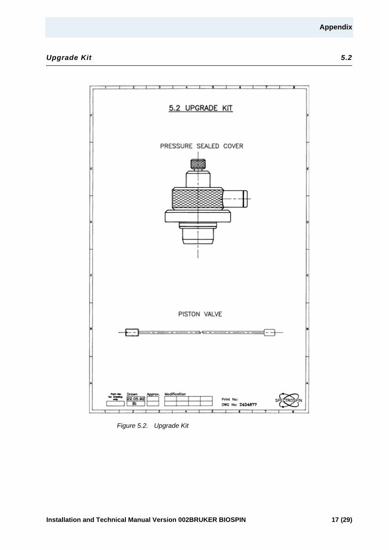
The Upgrade Kit consists of the piston valve and a pressure sealed cover (see "Upgrade Kit" on page 17).
To install the option:
1. Remove the blind screw (see "Basic Version" on page 16)
2. Insert the piston rod completely into the opening.
3. Screw the screw in until it is flush with the surface of the flange (see "Setup for Mode 1" on page 18)
NOTICEThe two-way lift valve which was used with the previous model (SUP Type 72) is no longer necessary and is not being delivered with the BST. Therefore, the lift hose should be connected directly to the white fitting.
Installation and Technical Manual Version 002BRUKER BIOSPIN 9 (29)
Setup
Connecting to the BSMS 3.3
Connect the 8-pin connector with the cable Z12152.
Connecting to the B-SN 18 3.4
Use the adapter cable Z12085 and the 3-pin original cable Z902.
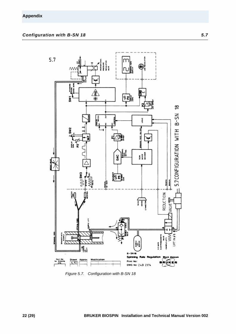
Since the BST uses only a very low lift gas flow, it is mandatory to install a pres-sure reduction valve Z4930) before the inlet of the B-SN18. This valve must be adjusted for a smooth lift action. For details, see the drawing in "Configuration with B-SN 18" on page 22.
Setup with a Sample Changer 3.5
When the BST is being used in conjunction with the sample changer, the informa-tion provided by the built-in light barrier in the BST is passed directly (in case of the B-SN 18) or indirectly (via BSMS) to the sample changer. Therefore, the light barrier cylinder used with the shim upper part type 72 is no longer needed.
When using the sample changer with the BSMS, connect the sample changer with the BSMS according to the instructions provided with the BSMS. The electri-cal connection between the BST and the BSMS is identical to the one described under section 3.3.
When configuring the BST to a sample changer and B-SN 18, use the adapter ca-ble Z12083, the original cable Z902, and the sample changer cable.
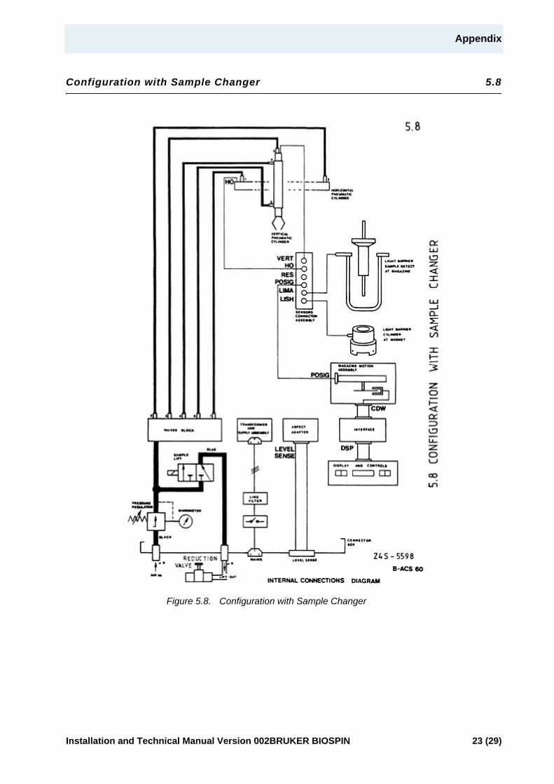
Since the BST uses only a very low lift gas flow, it is mandatory to install a pres-sure reduction valve Z4930 at the sample changer fitting labeled „LIFT OUT“. The operating pressure of the sample changer should be set to approx. 3 bar. The pressure reduction valve must the be adjusted for a smooth lift action. For details, see "Configuration with Sample Changer" on page 23.
IMPORTANTUse the non-magnetic screwdriver supplied with the option.
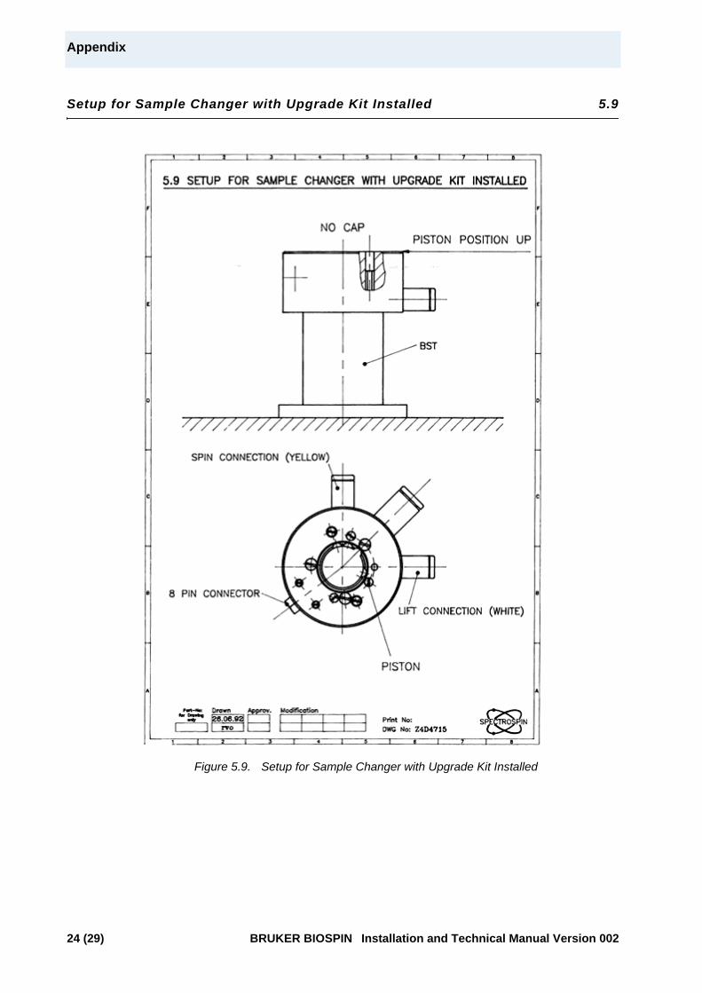
IMPORTANTFor operation of the sample changer with the Upgrade Kit installed, the screw of the piston valve must be in the UP position (see "Setup for Sample Changer with Upgrade Kit Installed" on page 24).
10 (29) BRUKER BIOSPIN Installation and Technical Manual Version 002
4Operation 4
Basic Version 4.1
The operation of the basic version is straightforward. The dust cover may be used at the operator‘s convenience to prevent dust from entering the system.
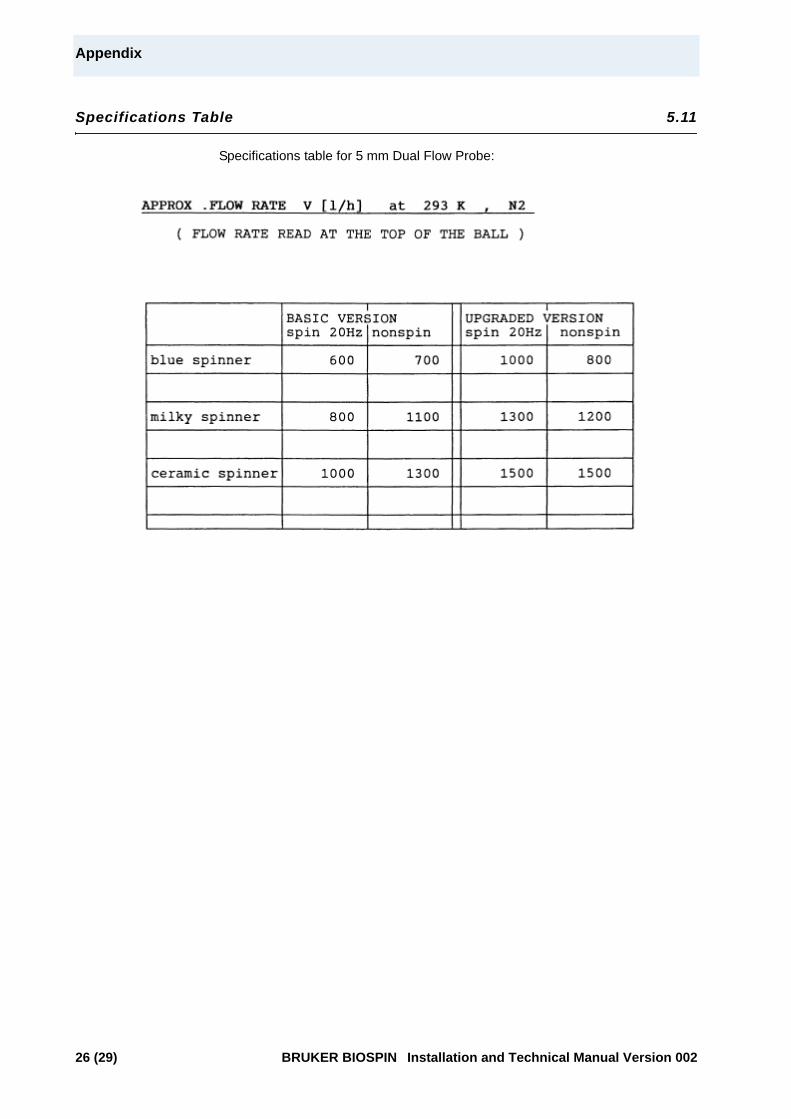
The achievable tempering gas flow rates are specified on the left side of the table in "Specifications Table" on page 26.
Upgraded Version 4.2
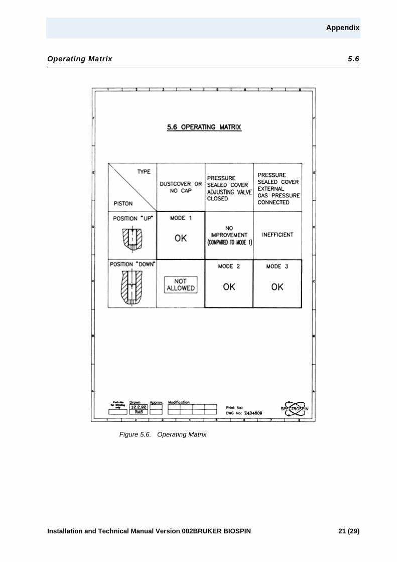
A BST equipped with this option may be operated in a number of different ways, depending on the requirements of the experiment. The following sections contain the necessary explanations for the operating modes 1 thru 3. For later reference, the configurations are summed up in "Operating Matrix" on page 21.
Mode 1 4.2.1
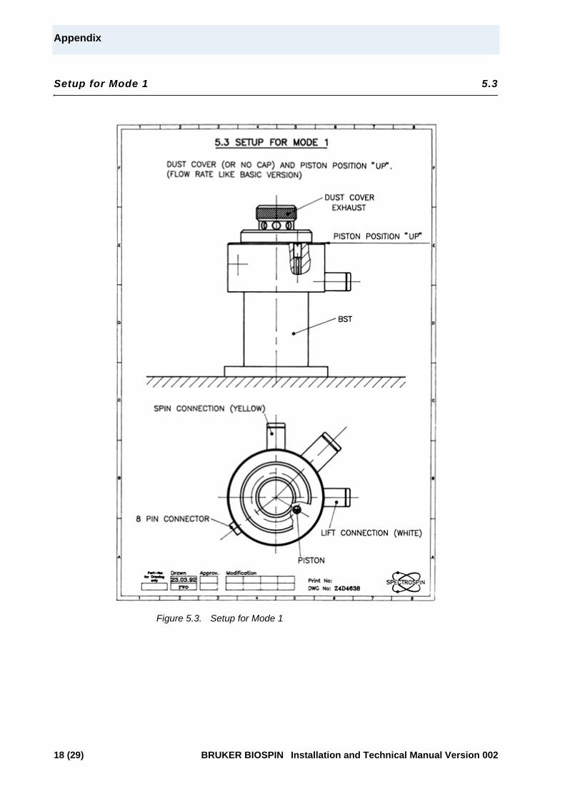
The piston valve is in the UP position (see "Setup for Mode 1" on page 18). The dust cover may be used at the operator‘s convenience.
In this mode the Upgrade Option is not active and the operation corresponds ex-actly to the basic version. For further details, see section 4.1.
Mode 2 4.2.2
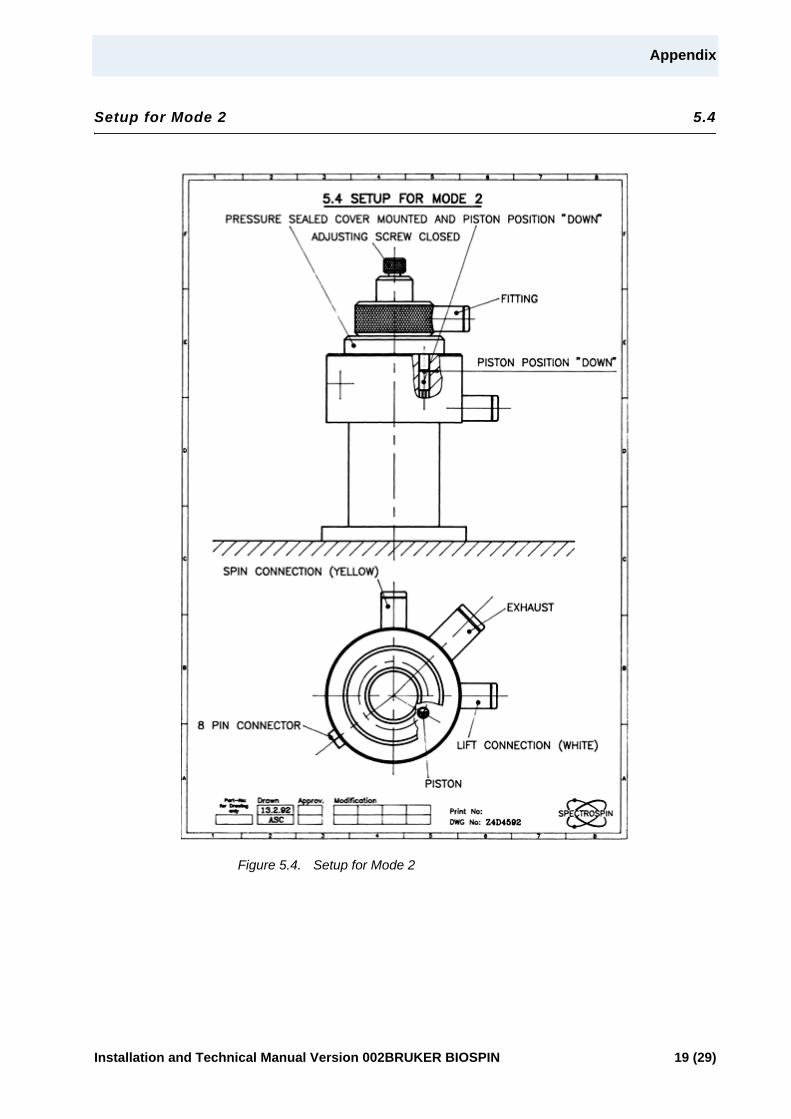
The piston valve is in the DOWN position. This is achieved by screwing it in com-pletely (see "Setup for Mode 2" on page 19).
Before inserting the sample, make sure that the tempering gas flow is set to a suf-ficiently low value (e.g. 200l/h). After lowering the sample, close the top of the BST with the pressure sealed cover. Secure it by turning it clockwise. Make sure that the adjusting screw in the pressure sealed cover is completely closed.
Now the required experiments may be performed with tempering gas flows up to the values rated on the right side of the table in "Specifications Table" on page 26.
IMPORTANTIn this mode (i.e. when not using the pressure sealed cover) it is mandatory for the piston valve to be in the UP position.
Installation and Technical Manual Version 002BRUKER BIOSPIN 11 (29)
Operation
Whenever it is desired to revert to operations without the pressure sealed cover (i.e. with the dust cover only or without any cover at all), the piston valve must be placed again in the UP position (see "Mode 1" on page 11).
Mode 3 4.2.3
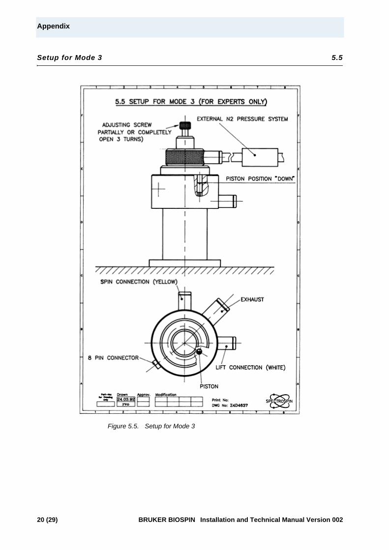
This mode is for those experts requiring the utmost tempering gas flow rates, ex-ceeding the capabilities of Mode 2. The operation in Mode 3 is achieved by con-necting an external gas supply to the fitting which is part of the pressure sealed cover as shown in "Setup for Mode 3" on page 20.
This allows to increase the pressure above the spinner by feeding a small gas flow backwards to the system. It is sufficient for the gas supply to be capable of providing several hundred liters per hour with a pressure of less than 0.5 bar.
For doing this, proceed with the following steps:
1. Make sure the piston is in the DOWN position.
2. Insert the sample and secure the pressure sealed cover according to the in-structions give under section 4.2.2.
3. Start increasing the tempering gas flow through the probe until problems with the lifting-off of the spinner start to manifest.
4. Open slowly the adjusting screw in the pressure sealed cover. Adjust the flow with this screw or with any other external device. This will result in an increase of the gas pressure above the spinner and will ultimately stabilize it. Nonspinning: Increase the external gas flow until the spinner sits firmly in
place. Spinning: Increase the external gas flow until a proper operation of the
spinner is achieved. Too much flow, however, will stop the spinner rotation.
CAUTIONBefore removing the pressure sealed cover, make sure that the tem-pering gas flow has been reduced to some safe value (e.g. 200 l/h). Failure to do so may cause the sample to be ejected (and possibly broken) the moment the cover is removed.
REMINDEROnce the system has been switched to Mode 2 (by screwing in the piston valve), the pressure sealed cover must be used at all times.
12 (29) BRUKER BIOSPIN Installation and Technical Manual Version 002
Operation
Terminating the experiment:
1. Reduce the tempering gas flow to a safe value (e.g. 200 1/h) or stop it com-pletely.
2. Shut off the external gas supply. Close the adjusting screw in the pressure sealed cover.
3. Now the pressure sealed cover may be removed and the sample ejected.
Whenever it is desired to revert to operations without the pressure sealed cover (i.e. with the dust cover only or without any cover at all), the piston valve must be placed again in the UP position - see "Mode 1" on page 11).
REMINDERBefore removing the pressure sealed cover, make sure that the tem-pering gas flow has been reduced to some safe value (e.g. 200 l/h). Failure to do so will cause the sample to be ejected (and possibly broken) the moment the cover is removed.
REMINDEROnce the system has been switched to Mode 3 (by screwing in the piston valve), the pressure sealed cover must be used at all times.
Installation and Technical Manual Version 002BRUKER BIOSPIN 13 (29)

Operation
14 (29) BRUKER BIOSPIN Installation and Technical Manual Version 002

5Appendix 5
List of illustrations or specifications in this Appendix:
"Basic Version"
"Upgrade Kit"
"Setup for Mode 1"
"Setup for Mode 2"
"Setup for Mode 3"
"Operating Matrix"
"Configuration with B-SN 18"
"Configuration with Sample Changer"
"Setup for Sample Changer with Upgrade Kit Installed"
"Electrical Wiring Diagram"
"Specifications Table"
Installation and Technical Manual Version 002BRUKER BIOSPIN 15 (29)

Appendix
Basic Version 5.1
Figure 5.1. Basic Version
16 (29) BRUKER BIOSPIN Installation and Technical Manual Version 002
Appendix
Upgrade Kit 5.2
Figure 5.2. Upgrade Kit
Installation and Technical Manual Version 002BRUKER BIOSPIN 17 (29)
Appendix
Setup for Mode 1 5.3
Figure 5.3. Setup for Mode 1
18 (29) BRUKER BIOSPIN Installation and Technical Manual Version 002
Appendix
Setup for Mode 2 5.4
Figure 5.4. Setup for Mode 2
Installation and Technical Manual Version 002BRUKER BIOSPIN 19 (29)
Appendix
Setup for Mode 3 5.5
Figure 5.5. Setup for Mode 3
20 (29) BRUKER BIOSPIN Installation and Technical Manual Version 002
Appendix
Operating Matrix 5.6
Figure 5.6. Operating Matrix
Installation and Technical Manual Version 002BRUKER BIOSPIN 21 (29)
Appendix
Configuration with B-SN 18 5.7
Figure 5.7. Configuration with B-SN 18
22 (29) BRUKER BIOSPIN Installation and Technical Manual Version 002
Appendix
Configuration with Sample Changer 5.8
Figure 5.8. Configuration with Sample Changer
Installation and Technical Manual Version 002BRUKER BIOSPIN 23 (29)
Appendix
Setup for Sample Changer with Upgrade Kit Installed 5.9
Figure 5.9. Setup for Sample Changer with Upgrade Kit Installed
24 (29) BRUKER BIOSPIN Installation and Technical Manual Version 002
Appendix
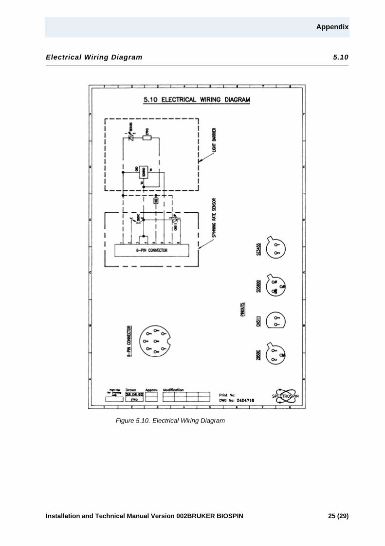
Electrical Wiring Diagram 5.10
Figure 5.10. Electrical Wiring Diagram
Installation and Technical Manual Version 002BRUKER BIOSPIN 25 (29)
Appendix
Specifications Table 5.11
Specifications table for 5 mm Dual Flow Probe:
26 (29) BRUKER BIOSPIN Installation and Technical Manual Version 002
Figures
1 Introduction 5
2 Configurations 7
3 Setup 9
4 Operation 11
5 Appendix 15Figure 5.1. Basic Version .......................................................................................16Figure 5.2. Upgrade Kit ..........................................................................................17Figure 5.3. Setup for Mode 1 ..................................................................................18Figure 5.4. Setup for Mode 2 ..................................................................................19Figure 5.5. Setup for Mode 3 ..................................................................................20Figure 5.6. Operating Matrix ..................................................................................21Figure 5.7. Configuration with B-SN 18 ..................................................................22Figure 5.8. Configuration with Sample Changer ......................................................23Figure 5.9. Setup for Sample Changer with Upgrade Kit Installed ...........................24Figure 5.10.Electrical Wiring Diagram .....................................................................25
Installation and Technical Manual Version 002BRUKER BIOSPIN 27 (29)

Figures
28 (29) BRUKER BIOSPIN Installation and Technical Manual Version 002

Installation and Technical Manual Version 002BRUKER BIOSPIN 29 (29)
End of Document
Bruker BioSpin
your solution partner
Bruker BioSpin Group
info@bruker�biospin.comwww.bruker�biospin.com
© B
ruke
r B
ioS
pin
Z311
23
Bruker BioSpin provides a world class, market�leadingrange of analysis solutions for your life and materialsscience needs.