broadcast operation - lnt · 3 broadcast operation 3.1 broadcast modes ......
TRANSCRIPT

Seminar
Ausgewählte Kapitel der Nachrichtentechnik, WS 2009/2010
LTE:Der Mobilfunk der Zukunft
Broadcast Operation
Christopher Schmidt
27. Januar 2010
Abstract — Long Term Evolution (LTE) provides an improved Multimedia Broad-cast Multicast Service (MBMS) compared to the Universal Mobile Telecommuni-cations System (UMTS), to distribute multimedia content to multiple users. Tothis end, LTE uses unicast communication as well as broadcast and multicast com-munication combined with a Single Frequency Network (SFN).The first part of this report describes the fundamentals needed for MBMS trans-mission in LTE. Afterwards, the second part deals with the Broadcast Operationitself, concluding with an outlook to following releases of the LTE standard.
1 Introduction
The number of application areas for high-bandwidth multimedia services, which require highdata rates, is rising. Thus, in 3GPP Long Term Evolution (LTE), the successor of UniversalMobile Telecommunications System (UMTS), the support of an enhanced version of MultimediaBroadcast Multicast Service (MBMS) has been an essential requirement. Therefore, an efficientbroadcasting mode is needed, to distribute the multimedia content to multiple users; the MBMStransmissions can be realised as single-cell transmission or as multi-cell transmission. Formulti-cell transmission, all participating cells transmit the same signal under the constraintof tight time-synchronization using the same spectral resources to enable the User Equipment(UE) to handle the received superimposed signal like one that has passed through a multipathpropagation channel; this is the concept of a Single Frequency Network (SFN).For this purpose, LTE provides a system architecture, which is able to switch between unicast,

2 Christopher Schmidt
multicast and broadcast communication on different carriers, namely dedicated and mixedcarrier, to transmit the multimedia content always in the most efficient way to multiple users.Besides, LTE is based on an air interface, which is robust against the multipath character ofthe wireless communiation channel. Hence, in LTE efficient MBMS transmission is possible dueto the properties of the Orthogonal Frequency Division Multiplex (OFDM) air interface [1].
2 Air Interface
2.1 Signal Propagation
LTE is a mobile terrestrial communication system, designed to increase capacity and data ratescompared to UMTS Release 6. UMTS is a third-generation mobile communications technologyand was the successor of the Global System for Mobile communications (GSM). Like everyterrestrial communication system, LTE has to deal with the typical terrestrial propagationchannel, which is dominated by path loss, multipath propagation and shadowing. Path loss isthe reduction of power flux density resulting from the propagation in free space without anyreflections or additional attenuation caused by obstacles. The transmitted power is distributedover the surface of a sphere, so it decreases proportionally with the square of the radius.In addition to the free space propagation, there is also a propagation loss due to obstacles. Thereceived power can be described by the power law Pr ∼ d−n, with d being the distance betweentransmitter and receiver and n the path loss exponent [6].In case of free space propagation, the path loss exponent is equal to 2, as a result of thequadratic decrease of power flux density. In a realistic environment there are e.g. buildings,mountains, and forests between transmitter and receiver, so the path loss exponent is usuallylarger than 2 (cf. Tab. 1).The Okumura-Hata model provides a mathematical description of the signal attenuation indifferent morphological environments which is caused by path loss and shadowing. This model isbased on a large number of measurements in rural, urban, and suburban areas to get informationabout attenuation, dependence on distance, carrier frequency, and transmitter and receiverantenna height.
Environment Path loss exponentFree Space 2Urban area 2,7 ... 3,5Urban area with shadowing 3 ... 5Inside buildings with direct line-of-sight 1,6 ... 1,8Inside buildings with shadowing 4 ... 6Inside factory buildings with shadowing 2 ... 3
Table 1: Environment and associated path loss exponent. [7]

Broadcast Operation 3
The transmitted signal is reflected at buildings, mountains and other terrestrial obstacles, soadditional propagation paths with different delays occur (cf. Fig. 1); this phenomenon is calledmultipath propagation. The result is a longer Channel Impulse Response (CIR), since thesepaths arrive at different delays at the receiver. The Power Delay Profile (PDP) describes theintensity of a received signal as a function of the time, which was transmitted over a multipathchannel. There is constructive and destructive interference dependent on the phase relations ofthe signal components. The resulting minima and maxima alternate at approximately half ofthe wavelength of the carrier frequency. Thus, there are changes in the strength of the receivedsignal within a few meters, so multipath fading is also called fast fading. The multipath fadingcan be modelled by a stochastic process.
Figure 1: Multipath Propagation [10]
Terrestrial obstacles also cause further attenuation of the transmitted signal; this phenomenon iscalled shadowing. The direct line-of-sight is interrupted, so only a part of the transmitted powercan be received in the shadowed areas. The size of the shadowed areas and the attenuation ofthe signal within this area are dependent on the morphological structure of the environment.Shadowing is usually considered as constant in a range of approximately 10 to 100 meters,depending on the size of the obstacles, so the attenuation due to shadowing changes slowlycompared to multipath effects; this effect is referred to as slow fading. Shadowing can alsobe modeled by a stochastic process. This process describes the statistical characteristic of themean received power of the multipath fading.Usually, the channel is modelled by static coefficients for path loss and shadowing. The time-variance of the CIR is dependent on the speed of the user, and the CIRs result as realizationsfrom their associated stochastic process [1] [6].

4 Christopher Schmidt
2.2 Orthogonal Frequency Division Multiplex (OFDM)
LTE uses Orthogonal Frequency Division Multiplexing (OFDM) in the downlink, as shown in[8]. OFDM is a digital multi-carrier modulation method, which distributes the modulateddata symbols to N orthogonal sub-carriers, with N being the length of the Discrete FourierTransform (DFT). The per subcarrier symbol rate is very low compared to a single-carriermodulation, because the symbol duration in each narrowband sub-carrier is N times longer.The insertion of a Guard Interval (GI) between the discrete-time OFDM symbols enables aconstructive combination of delayed paths at the receiver due to multipath propagation withoutInter-Symbol Interference (ISI). Therefore, OFDM is particularly suitable for broadband mobilecommunication systems like LTE. The mobility of the UE can also cause problems: Inter-carrierInterference (ICI) occurs, when the orthogonality of the sub-carriers is lost, e.g. as a result ofDoppler shift.
Figure 2: Insertion of a CP in OFDM [1]
In OFDM, the GI is realised as a Cyclic Prefix (CP) which repeats a defined number of discretetime samples from the end of an OFDM symbol at its beginning. The length of the CP alsodetermines the longest acceptable path delay; there is no ISI at the receiver if the maximumdelay path in the CIR arrives within the GI (cf. Fig. 2). The received signal for Single-InputSingle-Output (SISO) transmission is given by
ri[k] =J∑
j=1
hj,i[k] ∗ si[k] + ni[k] (1)
in the discrete-time domain. Provided that the GI is not exceeded the received signal in theDFT domain is given by
Ri[m] = Hi[m] · Si[m] + Ni[m], (2)
where i represents the OFDM symbol index, Si[m] the transmitted signal, Ni[m] the noise, mthe subcarrier index 0 ≤ m ≤ N − 1 for N being the DFT size, and Hi[m] =
∑Jj=1Hj,i[m] as
well as Hj,i[m] = DFTN{hj,i[k]} the CIR.

Broadcast Operation 5
2.3 Impact of Guard Interval Excess
In the following, the effect of an insufficient length of the CP is discussed. N is defined as theDFT size, G is the number of samples of the CP, and L is the number of non-zero taps of thechannel Power Delay Profile (PDP) ρ[k]. The ISI power can be calculated by
PISI =N+G−1∑k=G
|h[k]|2 (k −G)2
N2(3)
and the ICI power results in
PICI = 2N+G−1∑k=G
|h[k]|2N(k −G)− (k −G)2
N2, (4)
with being h[k] the CIR.The mathematical relation of PISI, accumulating the overlapping energy for k ≥ G, is plotted inFig. 3, as well as PS and PICI. The power of the ISI and the ICI increases when the boundaryof the CP is exceeded. Hence, the useful signal power PS is reduced. The useful signal powerPS is given by
PS =G−1∑k=0
|h[k]|2 +N+G−1∑k=G
|h[k]|2 (N − k +G)2
N2. (5)
The resulting Signal-to-Interference Ratio (SIR) is given by
SIR =PS
PISI + PICI
. (6)
Fig. 4 illustrates the SIR and shows the influence of an exceeded CP on the SIR. The SIRdecreases rapidly, because the signal power PS is reduced by the sum of PISI and PICI.
The SIR plotted in Fig. 4 is based on a rectangularly shaped PDP; this means, that all receiveddelayed paths arrive at the UE with the same power. In a realistic multipath environment, thepath power would decrease with an increasing delay, so the SIR would decrease slowlier withincreasing value of L, because the paths, which exceed the CP would have less power on average[1] [7].
2.4 Multicast/Broadcast Single Frequency Network (MBSFN)
In a Multi Frequency Network (MFN), the use of different carrier frequencies in different cellsis necessary to prevent high levels of interference especially for UEs located at the cell edges.Accordingly, the frequency reuse is low, because no surrounding cell is allowed to reuse the fre-quency. A Single Frequency Network (SFN) uses one common carrier frequency for all eNodeBsfor the simultaneous transmission in a multi-cell network (cf. Fig. 5). The eNodeBs have to be

6 Christopher Schmidt
Figure 3: PS, PISI, and PICI as a result of an exceeded CP [1]
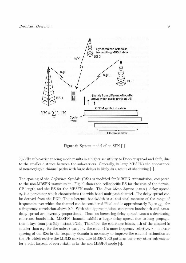
tightly time-synchronised to guarantee that the same information is transmitted at the sametime on the same set of OFDM subcarriers at every base-station. Fig. 6 illustrates an SFN,consisting of J = 3 Base Stations (BS)s. The composit CIR h[k] is given by the sum of J CIRslinking the UE with the BS, i.e. h[k] =
∑Jj=1 hj[k].
A receiver in this geographical SFN area will pick up multiple versions of the same signal fromdifferent eNBs with different time delays due to the different distances of the UE from the eNBs.The synchronisation enables the receiver to handle the multiple signal versions like multipathpropagation, because they appear as echoed paths from a single transmitter in an SFN; so thereis no additional complexity required for discrete-time channel equalization as long as the CP isnot exceeded.
In LTE, SFN transmission can be easily realized due to the OFDM air interface. The length ofthe CP of the OFDM modulation approximately restricts the maximum ISI/ICI free distancebetween the eNBs and the UE. As long as the sum of the propagation delay and maximumdelay of the CIR does not exceed the CP, there is no ISI and ICI. The PDP is dependent onthe morphology of the propagation environment. Thus, the length of the CP has to be adaptedto the environment of the SFN. In urban areas, the attenuation of the signal is higher than inrural areas, because, the path loss exponent is larger. This means that the effective range of atransmitted signal is shorter compared to rural areas and therefore the CP in urban areas can

Broadcast Operation 7
Figure 4: SIR as a result of an exceeded CP [1]
be shorter which is exploited for unicast transmission.The main advantage of an SFN is the transformation of inter-cell interference at the cell edgesinto useful signal energy by combining the different components constructively. The size of thecovered area can easily be increased by adding further eNBs on the same OFDM subcarriersto the SFN instead of allocating further spectrum for other frequencies in an MFN.The main drawback of an SFN is the requirement for time-synchronisation of all eNBs belong-ing to the SFN. This requires a synchronisation with an accuracy which should be considerablysmaller than the length of the CP. Otherwise, the CP will be exceeded and there will be de-structive interference due to delayed transmission, resulting in lower SIRs (cf. Fig. 4). LTEalso provides unicast transmission, because the eNBs used for the unicast cells do not have tobe synchronized in FDD mode, which means that the synchronization complexity is reduced[1] [7] [2].One of the main advantages of LTE, compared to UMTS Release 6, is the possibility of us-ing a multi-cell single frequency network for data broadcast. An SFN increases the spectralefficiency, due to the enhanced signal to interference-plus-noise ratio (SINR) in comparison tounicast transmission. The combination of the different received signal paths from different eNBsincreases the received signal energy, while the inter-cell interference is reduced particularly forusers which are located at the all border. Fig. 7 shows the coverage vs. the spectral efficiency;the size of the MBSFN area is used as parameter. When the SFN-area size increases, thenthe spectral efficiency improves at equal coverage: adding a first ring around the central cell

8 Christopher Schmidt
Figure 5: Multi Frequency Network vs. Single Frequency Network [9]
generates a significant gain in spectral efficiency as a result of the increased distance to theinterferers, i.e., the surrounding eNBs which transmit other data services. A further increase ofthe number of MBSFN cells surrounding the central cell results in a further but smaller benefit,caused by a decreased interference power and a smaller received useful signal energy, due tolarger distances between the UE and the additional eNBs.
In LTE, three different lengths of the CP are standardized: the normal CP, the extended CP,and an extended CP in combination with a smaller sub-carrier spacing paired with a doubledOFDM symbol length (cf. Fig. 8). Tab. 2 shows the different CP durations and the corre-sponding propagation distances.
CP mode GI duration Corresponding propagationTg distance dp = c · Tg
Normal CP (∆f = 15 kHz) 4,69 µs 1406 mExtended CP (∆f = 15 kHz) 16,67 µs 5000 mExtended CP (∆f = 7,5 kHz) 33,33 µs 10000 m
Table 2: CP mode and corresponding propagation distances and GI durations. [1]
In urban areas, the reach of the signal is reduced compared to a rural area, due to a larger valueof the path loss exponent as a result of the urban morphology; the use of a CP with a duration of16,7 µs duration is satisfactory. In contrast, the signals in a rural areas have a larger range dueto the smaller path loss exponent, so the usage of the extended CP with a duration of 33,3 µsmay be necessary. The corresponding propagation distance dp of 10000 m is sufficient, becauseat distances greater than 10000 m the path loss exponent is considerably increasing due to theearth curvature; hence, these eNBs have only negligible influence on the UE. In the 33,3 µsextended mode, the sub-carrier spacing (∆f) is halved to reduce the overhead, resulting of thedoubled OFDM symbol duration in comparison to the extended OFDM symbol duration. The
Broadcast Operation 9
Figure 6: System model of an SFN [1]
7,5 kHz sub-carrier spacing mode results in a higher sensitivity to Doppler spread and shift, dueto the smaller distance between the sub-carriers. Generally, in large MBSFNs the appearanceof non-negligble channel paths with large delays is likely as a result of shadowing [1].
The spacing of the Reference Symbols (RSs) is modified for MBSFN transmission, comparedto the non-MBSFN transmission. Fig. 9 shows the cell-specific RS for the case of the normalCP length and the RS for the MBSFN mode. The Root Mean Square (r.m.s.) delay spreadστ is a parameter which characterizes the wide-band multipath channel. The delay spread canbe derived from the PDP. The coherence bandwidth is a statistical measure of the range offrequencies over which the channel can be considered “flat” and is approximately BC ≈ 1
50στfor
a frequency correlation above 0.9. With this approximation, coherence bandwidth and r.m.s.delay spread are inversely proportional. Thus, an increasing delay spread causes a decreasingcoherence bandwidth. MBSFN channels exhibit a larger delay spread due to long propaga-tion delays from possibly distant eNBs. Therefore, the coherence bandwidth of the channel issmaller than e.g. for the unicast case, i.e. the channel is more frequency-selective. So, a closerspacing of the RSs in the frequency domain is necessary to improve the channel estimation atthe UE which receive the MBMS service. The MBSFN RS patterns use every other sub-carrierfor a pilot instead of every sixth as in the non-MBSFN mode [4].

10 Christopher Schmidt
Figure 7: Performance of an MBSFN network illustrated by means of coverage vs. spectralefficiency for various MBSFN area sizes [1].
The eNBs belonging to the SFN have to be tightly time-synchronised. This requires a synchro-nisation with accuracy considerably smaller than TG, so the adoption of satellite-based serviceslike GPS is necessary for synchronisation [1] [5].
3 Broadcast Operation
3.1 Broadcast Modes
The transmission of data to multiple users can be realised by three different transmission modes,which vary e.g. in exploitation of feedback, scheduling of UEs, and spectral efficiency.Unicast provides a bidirectional point-to-point transmission, so the same data has to be trans-mitted to each user individually. Hence, the network burden is increasing with the numberof transmitters, due to multiple transmissions of the same data. So, the overall spectral ef-ficiency is very poor when a broadcast to many UEs is realised by unicasting, especially forhigh-bandwidth multimedia applications. Due to the bidirectional communication, there is areturn channel for Channel Quality Information (CQI), which is needed for link adaptation.Broadcast is a downlink-only transmission mode which uses point-to-multipoint connections.The unidirectional communication comes with the absence of a return channel. Therefore, theeNB does not know anything about the individual channel conditions; accordingly, there is noindividual link adaptation for the broadcast mode. The data is only transmitted once for all

Broadcast Operation 11
Figure 8: Standardized LTE slots and associated CP lengths [1].
receivers in a geographical area, so the resource consumption is to a large extent independentof the number of users but relatively large, since it has to be ensured that a large percentageof all UEs can successfully decode the received data packets.Multicast is a special case of a broadcast. It is also a downlink-only point-to-multipoint trans-mission, but the content can only be received by a managed group of subscribers in the geo-graphical area. Multicast is, on the one hand, the most efficient mode to transmit the sameinformation to a limited number of users without using an individual connection to each user,but there is also no link adaptation due to the missing return channel on the other hand.In unicast communication, link adaptation due to the received CQI enables higher reliabilityor higher throughput, but the number of resources which have to be scheduled for each unicastuser increases linearly with the number of recipients, so there is a break even point, where theMBSFN throughput exceeds unicast throughput [1].Unfortunately, MBSFN transmission in LTE Release 8 does not allow for spatial multiplexing,in contrast to the unicast transmission mode. This means that unicasting can potentially real-ize much higher per user throughputs than MBSFN broadcast transmission in general.The Multimedia Broadcast Multicast Service (MBMS) in LTE is based on the UMTS Release6 MBMS Network Architecture, which is shown in Fig. 10.
MBMS, which was specified for the first time in 3GPP (3rd Generation Partnership Project)UMTS Release 6, provides the options unicast and broadcast/multicast to transmit data froma single point to multiple users by using the core network and the UMTS Terrestrial RadioAccess Network (UTRAN).

12 Christopher Schmidt
Figure 9: Reference symbols for non-MBSFN and MBSFN mode [1]
Figure 10: UMTS Release 6 unicast and broadcast/multicast modes
The network architecture can be divided into three parts: content provision, core network,and radio access network. The content providers are normally external to the core network,e.g. television broadcasters. The Broadcast-Multicast Service Center (BM-SC) is the interfacebetween the content providers and the core network, which receives the content, schedules theservices and manages the group membership. The Gateway GPRS Support Node (GGSN) andthe Serving GPRS Support Node (SGSN) are the entry points to the core network respectivelyRadio Access Network (RAN). Finally, the RAN transmits the MBMS data in the most effi-cient way; dependent on the number of receivers within a cell, a decision between unicast andbroadcast/multicast is made.UMTS Release 6 uses different scrambling codes in each cell for CDMA, also for multi-cellbroadcast transmission which prevents SFN-like broadcasting. Release 6 defines a single-celltransmission with different scrambling codes for different cells. The successor, Release 7, pro-vides the opportunity to realise multi-cell SFN transmission by using the same scrambling codesin all participating cells [3].

Broadcast Operation 13
3.2 MBMS Network Architecture
The architecture of the MBMS network in LTE is based on the UMTS Release 6 MBMS net-work architecture (cf. Fig. 10). Fig. 11 illustrates the design of the LTE network, includingSFN transmission. Obviously, the basic structure of an LTE network is identical to that of theUMTS network. The main difference lies in the air interface designs, which is based on OFDMfor LTE and CDMA for UMTS, respectively.
Figure 11: LTE MBMS network Architecture [11]
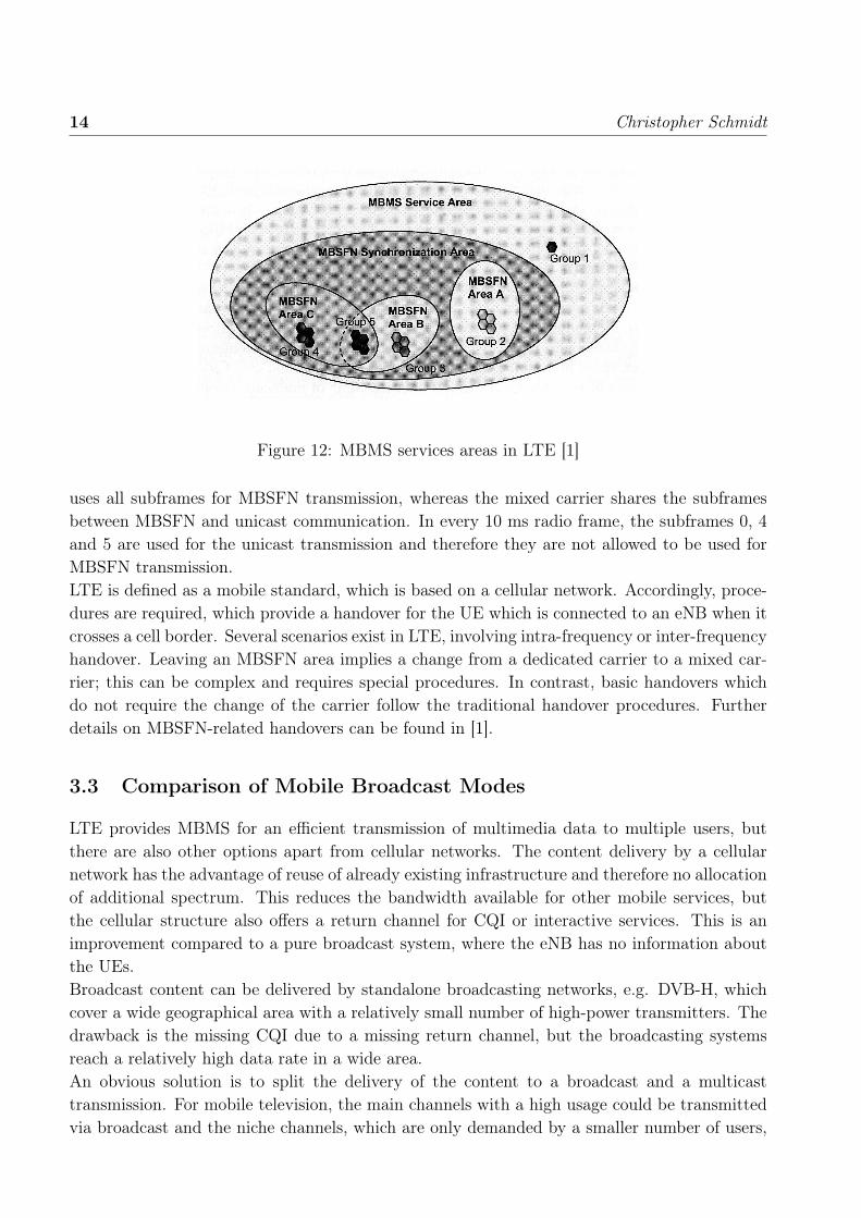
LTE enables the simultaneous deployment of unicast and multicast/broadcast communication.Therefore, different areas are defined within an MBMS service area, which can be seen inFig. 12. The MBMS service area is a geographical area, where MBMS can be applied. Withinthis area, there is the MBSFN synchronization area, where all eNBs can be time-synchronisedand therefore can offer MBSFN services. Inside the MBSFN synchronization area, there aredifferent MBSFN areas, in which MBSFN transmission is enabled (cf. Fig. 12, Groups 2, 3, 4and 5). The overlapping of different MBSFN areas (cf. Fig. 12, Group 5) is a special case of theMBSFN and necessitates a more complex configuration for the allocation of separate resourcesand signalling to support the different MBMS services which each involved area provides.There can also be cells inside the MBMS service area which do not belong to the MBSFNsynchronization area. These cells transmit the data by unicast communication, so there is noneed to time-synchronise the relevant eNBs (Fig. 12, Group 1).
LTE provides two kinds of carriers: a dedicated and a mixed carrier. The dedicated carrier
14 Christopher Schmidt
Figure 12: MBMS services areas in LTE [1]
uses all subframes for MBSFN transmission, whereas the mixed carrier shares the subframesbetween MBSFN and unicast communication. In every 10 ms radio frame, the subframes 0, 4and 5 are used for the unicast transmission and therefore they are not allowed to be used forMBSFN transmission.LTE is defined as a mobile standard, which is based on a cellular network. Accordingly, proce-dures are required, which provide a handover for the UE which is connected to an eNB when itcrosses a cell border. Several scenarios exist in LTE, involving intra-frequency or inter-frequencyhandover. Leaving an MBSFN area implies a change from a dedicated carrier to a mixed car-rier; this can be complex and requires special procedures. In contrast, basic handovers whichdo not require the change of the carrier follow the traditional handover procedures. Furtherdetails on MBSFN-related handovers can be found in [1].
3.3 Comparison of Mobile Broadcast Modes
LTE provides MBMS for an efficient transmission of multimedia data to multiple users, butthere are also other options apart from cellular networks. The content delivery by a cellularnetwork has the advantage of reuse of already existing infrastructure and therefore no allocationof additional spectrum. This reduces the bandwidth available for other mobile services, butthe cellular structure also offers a return channel for CQI or interactive services. This is animprovement compared to a pure broadcast system, where the eNB has no information aboutthe UEs.Broadcast content can be delivered by standalone broadcasting networks, e.g. DVB-H, whichcover a wide geographical area with a relatively small number of high-power transmitters. Thedrawback is the missing CQI due to a missing return channel, but the broadcasting systemsreach a relatively high data rate in a wide area.An obvious solution is to split the delivery of the content to a broadcast and a multicasttransmission. For mobile television, the main channels with a high usage could be transmittedvia broadcast and the niche channels, which are only demanded by a smaller number of users,

Broadcast Operation 15
are transmitted via multicast or unicast (cf. Fig. 13). Hence, the resource consumption wouldbe optimised by combining unicast, multicast and broadcast transmission [1].
Figure 13: The "Long Tail of Content" [1]
4 Outlook and Conclusion
4.1 Outlook
MBMS in LTE is not specified in Release 8, because other aspects of the LTE standard hadhigher priority for the commercial deployment; thus, not all innovations were specified in thefirst LTE release. However, the essential components for deployment of MBMS are alreadyspecified in Release 8 to ensure forward-compatibility.Furthermore, Multiple Input Multiple Output (MIMO) MBSFN transmission is unlikely to befeasible in following releases.
4.2 Conclusion
The initialization of considerably higher data rates enables high-bandwidth multimedia appli-cations via MBSFN. Due to MBSFN transmission, the r.m.s. delay spread increases, so the

16 Christopher Schmidt
coherence bandwidth is reduced which requires a higher reference symbol density in frequencydirection. Additionally, LTE provides different CP modes for the OFDM air interface to re-spond to the signal propagation effects. LTE combines unicasting with broadcast/multicast ondifferent carriers and provides handover procedures for mobile users. Therefore, LTE providesa higher cell edge throughput for MBMS services in comparison to UMTS.
References
[1] S. Sesia, I. Toufik and M. Baker: LTE – The UMTS Long Term Evolution, Wiley2009.
[2] M. Konrad, W. Gerstacker and W. Koch: Robust MBSFN Transmission Using theGolden Code, IEEE Workshop on Mobile Computing and Networking Technologies(WMCNT), St. Petersburg, 2009.
[3] 3GPP TS 25.346 V7.7.0, Introduction of the Multimedia Broadcast Multicast Service(MBMS) in the Radio Access Network, Technical Specification Group Radio AccessNetwork, 2008.
[4] 3GPP TS 36.211 V8.4.0, Evolved Universal Terrestrial Radio Access (E–UTRA);Physical Channels and Modulation, Technical Specification Group Radio Access Net-work, 2008.
[5] T. Rappaport: Wireless Communications: Principles and Practice, 2nd Edition, Pren-tice Hall, 2001.
[6] W. Koch: Lecture Notes: Fundamentals of Mobile Communication, Lecture in WS2009/2010.
[7] A. Heuberger: Lecture Notes: Digital Broadcasting Systems, Lecture in SS 2009.
[8] S. Zarai: OFDM & Downlink Physical Layer Design, Seminar Ausgewählte Kapitelder Nachrichtentechnik: LTE – Der Mobilfunk der Zukunft, 2009.
[9] http://www.enensys.com/solutions/ip-distribution.html, 13.01.2010.
[10] http://www.cisco.com/en/US/docs/internetworking/technology/handbook/wireless.html,13.01.2010.
[11] G. Fettweis: LTE Netzwerk und Systemaspekte für die die digitale Rundfunkübertra-gung, www.vodafone-chair.com/staffkrondorf/IRT_Workshop.pdf, 13.01.2010.