broadcast · 2019-07-17 · broadcast news am fm television published by the radio corporation of...
TRANSCRIPT
I-KW UHF TRANSMITTER
Basic Buy for UHF TV Stations . . . Pg. 8
Vol. No. 66 Sept.-Oct., 1951
www.americanradiohistory.com
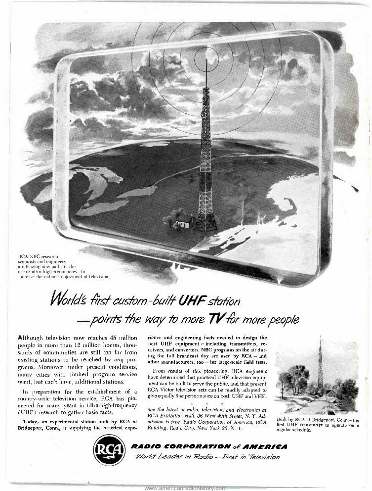
RCA -NBC research scientists and engineers are blazing new paths in the use of ultra -high frequencies -to increase the nation's enjoyment of television.
Gkr/c/S 4-sf cus'om - deu# UHFstarro/7
pol/7fs fhe way fo more 71 ñr more people Although television now reaches 45 million people in more than 12 million homes, thou- sands of communities are still too far from existing stations to be reached by any pro- grams. Moreover, under present conditions, mane cities with limited program service want, but can't have, additional stations.
In preparation for the establishment of a country -wide television service, RCA has pio- neered for many years in ultra- high- frequency (UHF) research to gather basic facts.
Today -an experimental station built by RCA at Bridgeport, Conn., is supplying the practical expe-
rience and engineering facts needed to design the best UHF equipment - including transmitters, re- ceivers, and converters. NBC programs on the air dur- ing the full broadcast day are used by RCA - and other manufacturers, too - for large -scale field tests.
From results of this pioneering, RCA engineers have determined that practical UHF television equip- ment can be built to serve the public, and that present RCA Victor television sets can be readily adapted to give equally fine performance on both UHF and VHF.
See the latest in radio, television, and electronics at RCA Exhibition Hall, 36 West 49th Street, N. Y. Ad- mission is free. Radio Corporation of America, RCA Building, Radio City, New York 20, N. Y.
Built by RCA at Bridgeport, Conn. -the first UHF transmitter to operate on a regular schedule.
RAD /O CORPORAT/OM of AMER /CA Wor /a' Leader in Ratio - First in 7 /eisiori
www.americanradiohistory.com
Broadcast News AM FM TELEVISION
Published by the
RADIO CORPORATION OF AMERICA ENGINEERING PRODUCTS DEPARTMENT ... CAMDEN, NEW JERSEY
NUMBER 66 SEPTEMBER -OCTOBER, 1951
Subscription Rates
In continental U. S. A. . $4.00 for 12 issues In other countries - $5.00 for 12 issues
JOHN P. TAYLOR, Editor W. O. HADLOCK, Managing Editor
M. L. GASKILL, E. B. MAY, E. C. MASON, W. R. COULTER, Associate Editors
Contents
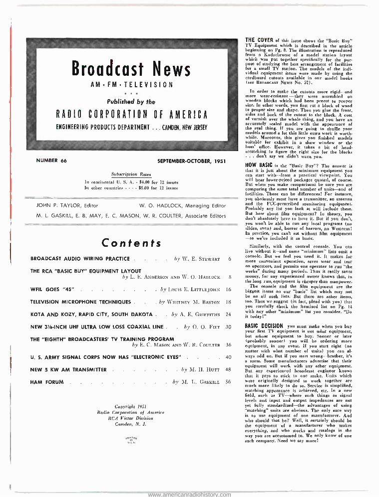
THE COVER of this issue shows the `Basic Buy" TV Equipment which is described in the article beginning on Pg. 8. The illustration is reproduced from a Kodachrome of a model station layout which was put together specifically for the pur- pose of studying the best arrangement of facilities for a small TV station. The models of the indi- vidual equipment items were made by using the cardboard cutouts available in our model books (see BROADCAST NEWS No. 52).
In order to make the cutouts more rigid -and more wear-resistant - they were assembled on wooden blocks which had been precut to proper size. In other words, you first cut a block of wood to proper size and shape. Then you glue the front, sides and back of the cutout to the block. A coat of varnish over the whole thing, and you have an accurately scaled model with the appearance of the real thing. If you are going to shuffle your models around a lot this little extra work is worth. while. Moreover, this gives you finished models suitable for exhibit in a show window or the boss' office. However, it takes a bit of head - scratching to figure the right size for the blocks ... don't say we didn't wart, you
HOW BASIC is the "Basic Buy "? The answer is that it is just about the minimum equipment you can start with -from a practical viewpoint. You will hear lowerpriced packages quoted, of course. But when you make comparisons be sure you are comparing the same total number of units -and of facilities. There can be differences! For instance,
-= you obviously must have a transmitter, an antenna
BROADCAST AUDIO WIRING PRACTICE . by W. E. STEWART 6
THE RCA "BASIC BUY" EQUIPMENT LAYOUT by L. E. ANDERSON AND W. O. HADLOCK 8
WFIL GOES "45" . . by Louis E. LITTLEJOHN 16
TELEVISION MICROPHONE TECHNIQUES . . by WHITNEY M. BASTON 18
KOTA AND KOZY, RAPID CITY, SOUTH DAKOTA . . by A. E. GRIFFITHS 24
NEW 3tß -INCH UHF ULTRA LOW LOSS COAXIAL LINE . . by O. O. FIET 30
THE "EIGHTH" BROADCASTERS' TV TRAINING PROGRAM by E. C. MASON AND W. R. COULTER 36
U. S. ARMY SIGNAL CORPS NOW HAS "ELECTRONIC EYES" . . 40
NEW 5 KW AM TRANSMITTER . by M. H. HUTT 48
HAM FORUM . by M. L. GASKILL 56
Copyright 1951
Radio Corporation of America RCA Victor Division
Camden, N. J.
and the FCC -prescribed monitoring equipment. Probably any list you look at will include these. But how about film equipment? In theory, you don't absolutely have to have it. But if you don't, you won't be able to run any local programs (no slides, even) and, horror of horrors, no Westerns! In practice, you can't eat without film equipment -so we've included it as basic.
Similarly, with the control console. You can live without it -and some "minimum" lists omit a console. But we feel you need it. It makes for more convenient operation, saves wear and tear on operators, and permits one operator to run "the works" during many periods. Thus it really saves money, for any experienced owner knows that, in the long run, equipment is cheaper than manpower.
The console and the film equipment are the biggest items on our "basic" list which may not be on all such lists. But there are other items, too. Thus we suggest (in fact, plead with you) that you carefully check the itemized list on Pg. 14 with any other "minimum" list you consider. "Do it today!"
BASIC DECISION you must make when you buy your first TV equipment is not what equipment, but whose equipment to buy. Sooner or later (probably sooner) you will be ordering more equipment, in any event. If you start right (no matter with what number of units) you can al- ways add on. But if you start wrong -brother, it's a mess. Some manufacturers advertise that their equipment will work with any other equipment. But any experienced broadcast engineer knows that it pays to stick to one make. Units which were originally designed to work together are much more likely to do so. Service is simplified, matching appearance is achieved, etc. In a new field, such as TV -where such things as signal levels and input and output impedances are not yet fully standardized -the advantages of using "matching" units are obvious. The only sure way is to use equipment of one manufacturer. And who should that be? Well, it certainly should be the equipment of a manufacturer who makes everything, and who stocks and catalogs in the way you are accustomed to. We only know of one such company. Need we say more!
www.americanradiohistory.com
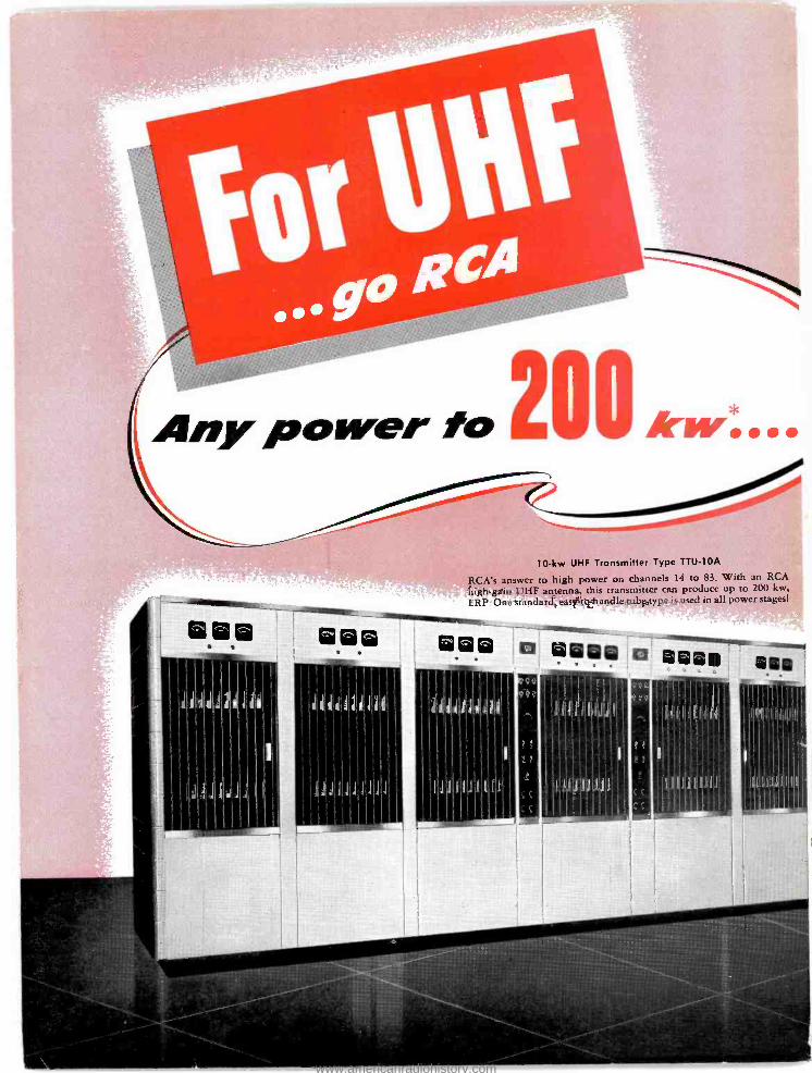
Any power fo 200 Arrw....
10 -kw UHF Transmitter Type TTU -10A
RCA's answer to high power on channels 14 to 83. With an RCA
high -gain UHF antenna, this transmitter can produce up to 200 kw,
ERP. One standard, easy -to- handle tube type is used in all power stages!
gi ® ®Q®iii - . I
www.americanradiohistory.com
sea
._ la 111/11! ®®á ® óón
Ja1a:JdlJ
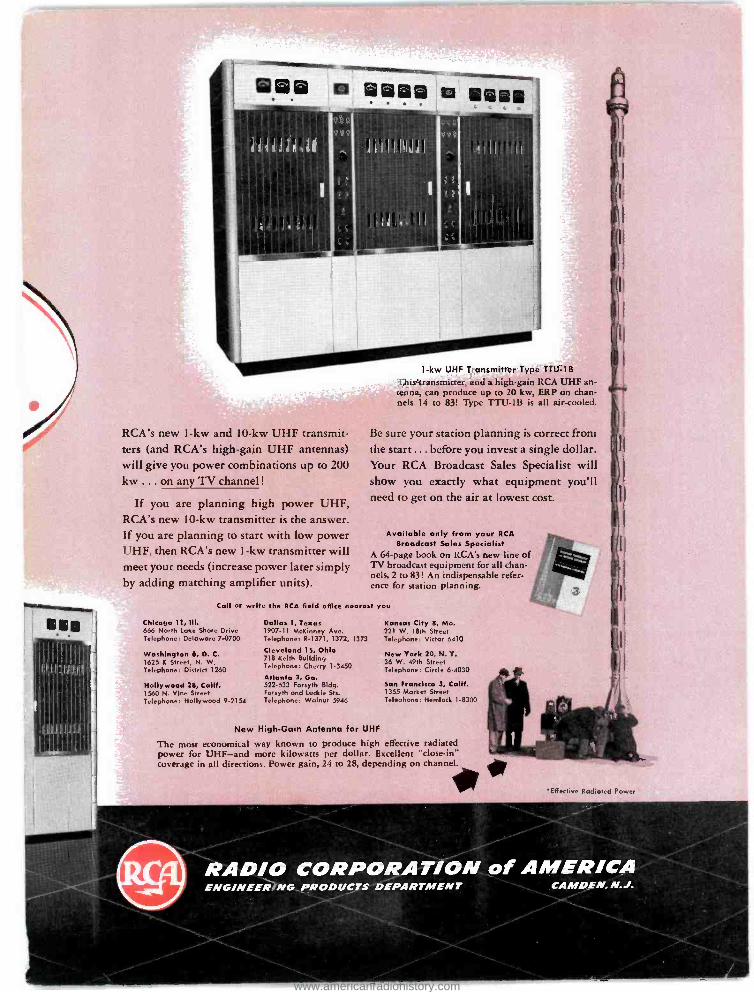
RCA's new 1 -kw and 10 -kw UHF transmit- ters (and RCA's high -gain UHF antennas) will give you power combinations up to 200
kw ... on any TV channel !
If you are planning high power UHF, RCA's new 10 -kw transmitter is the answer. If you are planning to start with low power UHF, then RCA's new 1 -kw transmitter will meet your needs (increase power later simply by adding matching amplifier units).
1 -kw UHF Transmitter Type TTU -1B
This transmitter, and a high -gain RCA UHF an- tenna, can produce up to 20 kw, ERP on chan- nels 14 to 83! Type TTU -1B is all air -cooled.
Be sure your station planning is correct from the start ... before you invest a single dollar. Your RCA Broadcast Sales Specialist will show you exactly what equipment you'll need to get on the air at lowest cost.
Available only from your RCA Broadcast Sales Specialist
A 64 -page book on RCA's new line of TV broadcast equipment for all chan- nels, 2 to 83! An indispensable refer- ence for station planning.
Call or write the RCA field office nearest you
Chicago 11, 111.
666 North Lake Shore Drive Telephone: Delaware 7 -0700
Washington 6, D. C. 1625 K Street, N. W. Telephone: District 1260
Hollywood 28, Calif. 1560 N. Vine Street Telephone: Hollywood 9 -2154
Dallas 1, Texas 1907 -11 McKinney Ave. Telephone: R -1371, 1372, 1373
Cleveland 15, Ohio 718 Keith Building Telephone: Cherry 1-3450
Atlanta 3, Ga. 522 -533 Forsyth Bldg. Forsyth and Luckie Sts. Telephone: Walnut 5946
Kansas City 8, Mo. 221 W. 18th Street Telephone: Victor 6410
New York 20, N. Y. 36 W. 49th Street Telephone: Circle 6 -4030
San Francisco 3, Calif. 1355 Market Street Telephone: Hemlock 1.8300
New High -Gain Antenna for UHF
The most economical way known to produce high effective radiated power for UHF -and more kilowatts per dollar. Excellent "close -in" coverage in all directions. Power gain, 24 to 28, depending on channel.
"Effective Radiated Power
ENGINEERING PRODUCTS DEPARTMENT
www.americanradiohistory.com
-WAM. ray
unisluma IMM31/01.
ANNOUNCE
TUOICI 1110111111111,111 IN COMM WM
itIONSuma 'STUDIO
ISO/1(TM. ROOM
PRO.1101011
NON
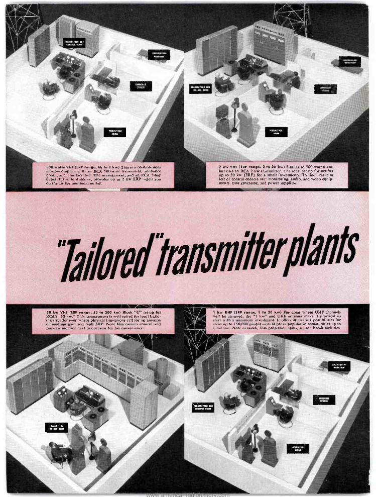
500 watts VHF (ERP range, 1/2 to 2 kw) This is a control-room set-up-complete with an RCA 500-watt transmitter, announce booth, and film facilities. The arrangement, and an RCA 5-bay Super Turnstile Antenna, provides up to 2 kw ERP*-gets you on the air for minimum outlay.
2 kw VHF (ERP range, 2 to 20 kw) Similar to 500-watt plant, but uses an RCA 2-kw transmitter. The ideal set-up for getting up to 20 kw (ERP) for a small investment. "In line" racks at left of control console are: monitoring, audio, and video equip- ments, sync generator, and power supplies.
WW1 lik111571#91011#
50 kw VHF (ERP range, 50 to 200 kw) Block "U" set-up for RCA's "50-kw." This arrangement is well suited for local build- ing situations-or where physical limitations call for an antenna of medium gain and high ERP. Note film camera control and preview monitor next to operator for his convenience.
1 kw UHF (ERP range, 1 to 20 kw) For areas where UHF channels will be assigned, the "1 kw" and UHF antenna make it practical to start with a minimum investment. It offers interesting possibilities for areas up to 150,000 people-could prove popular in communities up to I million. Note network, film projection spots, station break facilities.
101110111
ANNOUNCE
STUDIO
MANUMITS° AND
CONTROL PM
MAMBO In. MTN. NMI
0010C110. 1110011
www.americanradiohistory.com
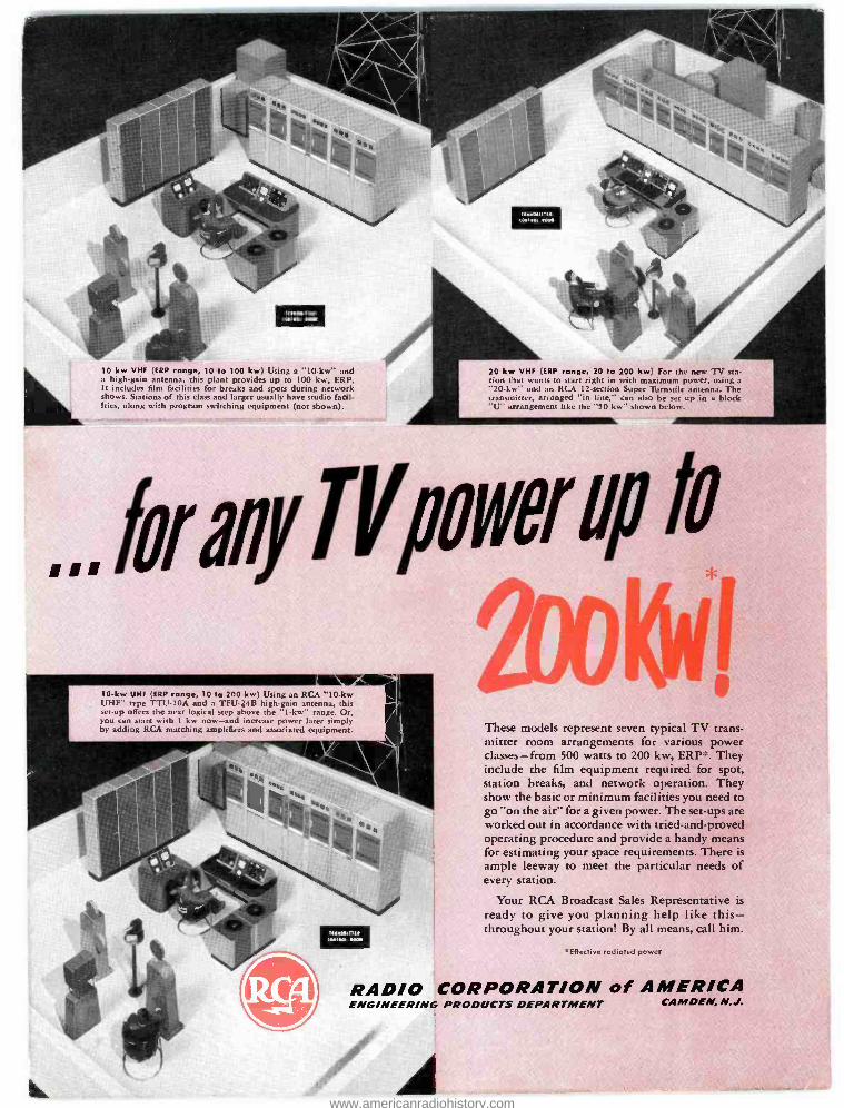
10 kw VHF (ERP range, 10 to 100 kw) Using a "10 -kw" and a high -gain antenna, this plant provides up to 100 kw, ERP. It includes film facilities for breaks and spots during network shows. Stations of this class and larger usually have studio facil- ities, along with program switching equipment (not shown).
20 kw VHF (ERP range, 20 to 200 kw) For the new TV sta- tion that wants to start right in with maximum power, using a "20 -kw" and an RCA 12- section Super Turnstile antenna. The transmitter, arranged "in line," can also be set up in a block "U" arrangement like the "50 kw" shown below.
,,, farMylV "Net up tv
Ivi 10 -kw UHF (ERP range, 10 to 200 kw) Using an RCA "10 -kw UHF" type TTU -10A and a TFU -24B high -gain antenna, this set -up offers the next logical step above the "1 -kw" range. Or, you can start with 1 kw now -and increase power later simply by adding RCA marching amplifiers and associated equipment.
tswtrnr arts. sw
These models represent seven typical TV trans- mitter room arrangements for various power classes -from 500 watts to 200 kw, ERP. They include the film equipment required for spot, station breaks, and network operation. They show the basic or minimum facilities you need to go "on the air" for a given power. The set -ups are worked out in accordance with tried -and -proved operating procedure and provide a handy means for estimating your space requirements. There is ample leeway to meet the particular needs of every station.
Your RCA Broadcast Sales Representative is ready to give you planning help like this - throughout your station! By all means, call him.
'Effective radiated power
RADIO CORPORATION of AMERICA ENGINEERING PRODUCTS DEPARTMENT CAMDEN, N. J.
www.americanradiohistory.com
4.L .L: I:wL3 L Yï:nMw WMi"4
rïtélsïifC iYLy.5,- ~y - áJtiYrn n'i . .-s-rì .o- m r tw, \:'*."
lUtti.liae'- -
r r.. . .
w
-
. " ..dN í 5..lb.éLfr:4ms=a aee_
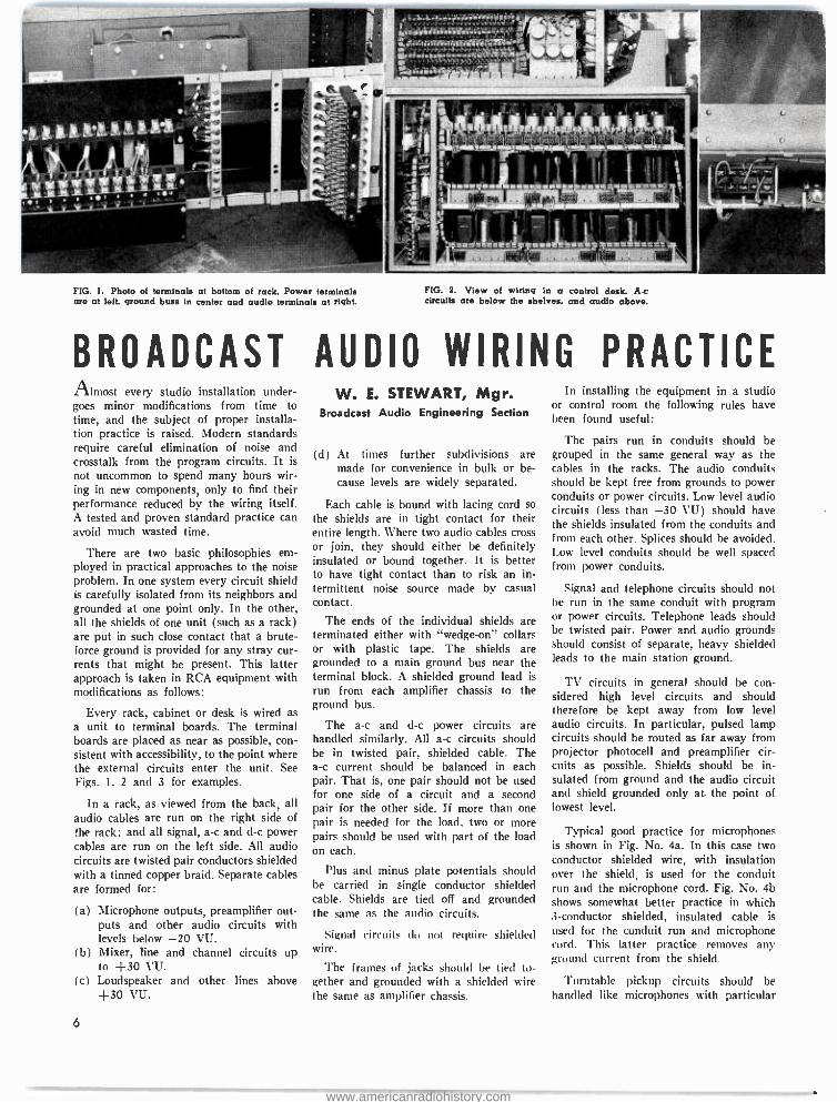
FIG. I. Photo of terminals at bottom of rack. Power terminals are at left, ground buss in center and audio terminals at right.
FIG. 2. View of wiring in a control desk. A.c circuits are below the shelves, and audio above.
BROADCAST AUDIO WIRING PRACTICE Almost every studio installation under- goes minor modifications from time to time, and the subject of proper installa- tion practice is raised. Modern standards require careful elimination of noise and crosstalk from the program circuits. It is
not uncommon to spend many hours wir- ing in new components, only to find their performance reduced by the wiring itself. A tested and proven standard practice can avoid much wasted time.
There are two basic philosophies em- ployed in practical approaches to the noise problem. In one system every circuit shield is carefully isolated from its neighbors and grounded at one point only. In the other, all the shields of one unit (such as a rack) are put in such close contact that a brute - force ground is provided for any stray cur- rents that might be present. This latter approach is taken in RCA equipment with modifications as follows:
Every rack, cabinet or desk is wired as a unit to terminal boards. The terminal boards are placed as near as possible, con- sistent with accessibility, to the point where the external circuits enter the unit. See Figs. 1. 2 and 3 for examples.
In a rack, as viewed from the back, all audio cables are run on the right side of the rack; and all signal, a -c and d -c power cables are run on the left side. All audio circuits are twisted pair conductors shielded with a tinned copper braid. Separate cables are formed for:
(a) Microphone outputs, preamplifier out- puts and other audio circuits with levels below -20 VU.
(b) Mixer, line and channel circuits up to +30 VU.
(c) Loudspeaker and other lines above +30 VU.
6
W. E. STEWART, Mgr. Broadcast Audio Engineering Section
(d) At times further subdivisions are made for convenience in bulk or be- cause levels are widely separated.
Each cable is bound with lacing cord so the shields are in tight contact for their entire length. Where two audio cables cross or join, they should either be definitely insulated or bound together. It is better to have tight contact than to risk an in- termittent noise source made by casual contact.
The ends of the individual shields are terminated either with "wedge -on" collars or with plastic tape. The shields are grounded to a main ground bus near the terminal block. A shielded ground lead is
run from each amplifier chassis to the ground bus.
The a -c and d -c power circuits are handled similarly. All a -c circuits should be in twisted pair, shielded cable. The a -c current should be balanced in each pair. That is, one pair should not be used for one side of a circuit and a second pair for the other side. If more than one pair is needed for the load. two or more pairs should be used with part of the load on each.
Plus and minus plate potentials should be carried in single conductor shielded cable. Shields are tied off and grounded the same as the audio circuits.
Signal circuits du not require shielded wire.
The frames of jacks should be tied to- gether and grounded with a shielded wire the same as amplifier chassis.
In installing the equipment in a studio or control room the following rules have been found useful:
The pairs run in conduits should be grouped in the same general way as the cables in the racks. The audio conduits should be kept free from grounds to power conduits or power circuits. Low level audio circuits (less than -30 VU) should have the shields insulated from the conduits and from each other. Splices should be avoided. Low level conduits should be well spaced from power conduits.
Signal and telephone circuits should not be run in the same conduit with program or power circuits. Telephone leads should be twisted pair. Power and audio grounds should consist of separate, heavy shielded leads to the main station ground.
TV circuits in general should be con- sidered high level circuits and should therefore be kept away from low level audio circuits. In particular, pulsed lamp circuits should be routed as far away from projector photocell and preamplifier cir- cuits as possible. Shields should be in- sulated from ground and the audio circuit and shield grounded only at the point of lowest level.
Typical good practice for microphones is shown in Fig. No. 4a. In this case two conductor shielded wire, with insulation over the shield, is used for the conduit run and the microphone cord. Fig. No. 4b shows somewhat better practice in which 3- conductor shielded, insulated cable is
used for the conduit run and microphone cord. This latter practice removes any ground current from the shield.
Turntable pickup circuits should be handled like microphones with particular
www.americanradiohistory.com
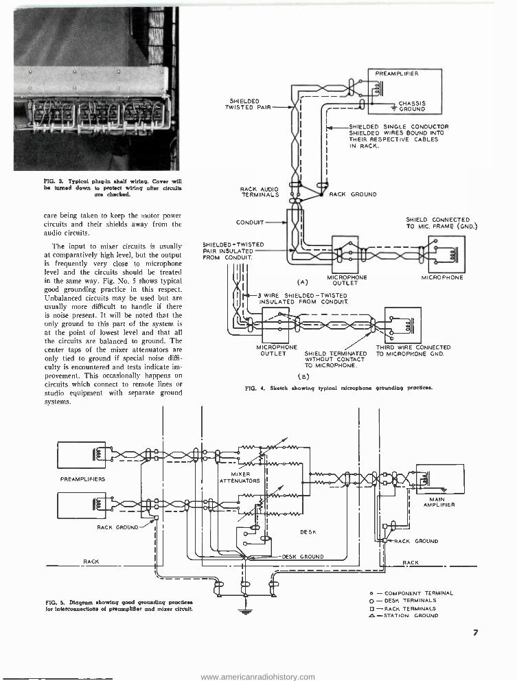
FIG. 3. Typical plug -In shelf wiring. Cover will be turned down to protect wiring after circuits
are checked.
care being taken to keep the motor power circuits and their shields away from the audio circuits.
The input to mixer circuits is usually at comparatively high level. but the output is frequently very close to microphone level and the circuits should be treated in the same way. Fig. No. 5 shows typical good grounding practice in this respect. Unbalanced circuits may be used but are usually more difficult to handle if there is noise present. It will be noted that the only ground to this part of the system is
at the point of lowest level and that all the circuits are balanced to ground. The center taps of the mixer attenuators are only tied to ground if special noise diffi- culty is encountered and tests indicate im- provement. This occasionally happens on
circuits which connect to remote lines or studio equipment with separate ground systems.
SHIELDED TWISTED PAIR
..,*- SHIELDED SINGLE CONDUCTOR SHIELDED WIRES BOUND INTO THEIR RESPECTIVE CABLES IN RACK.
RACK AUDIO TERMINALS
CONDUIT
SHIELDED-TWISTED PAIR INSULATED FROM CONDUIT.
RACK GROUND
SHIELD CONNECTED TO MIC. FRAME (CND.)
(A) MICROPHONE
OUTLET
3 WIRE SHIELDED -TWISTED INSULATED FROM CONDUIT.
M CROPHONE OUTLET SHIELD TERMINATED
WITHOUT CONTACT TO MICROPHONE.
(B)
MICROPHONE
TH RD WIRE CONNECTED TO MICROPHONE GND
FIG. 4. Sketch showing typical microphone grounding practices.
M N . t
PREAMPLIFIERS
I I
MIXER ATTENUATORS
Jo. F ;1 - - 1
RACK GROUND -'
RACK
DESK
DESK GROUND
FIG. 5. Diagram showing good grounding practices for interconnections of preamplifier and mixer circuit.
RACK
MAIN AMPLIFIER
CK GROUND
J RACK
o - COMPONENT TERMINAL 0 - DESK TERMINALS
-RACK TERMINALS LI- STATION GROUND
7
www.americanradiohistory.com
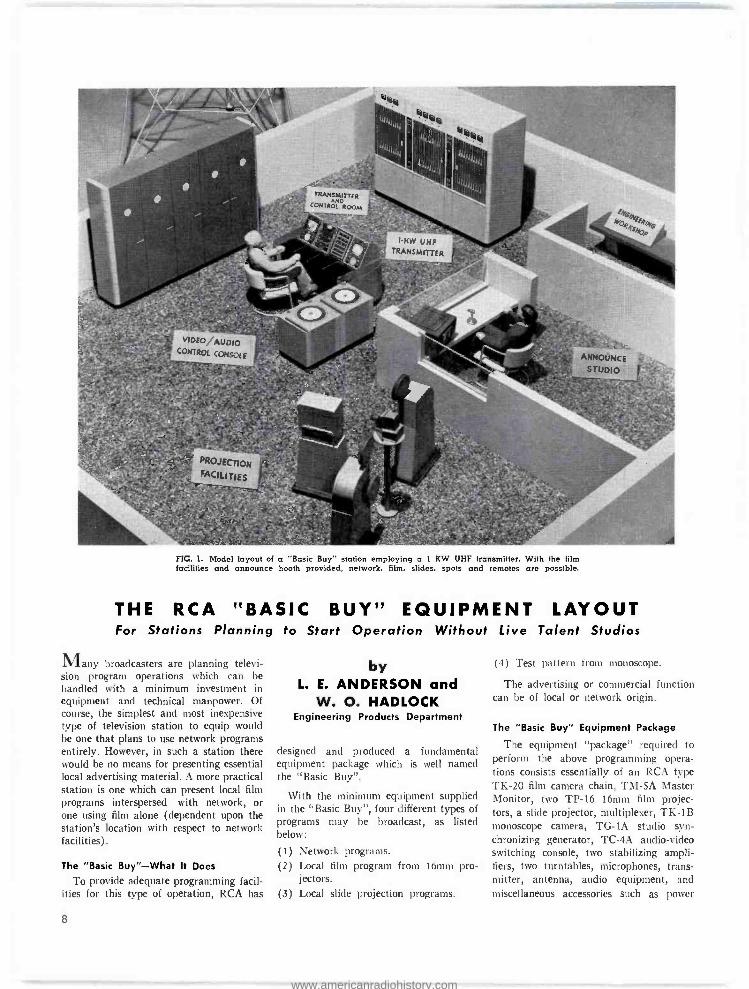
FIG. 1. Model layout of a "Basic Buy" station employing a 1 KW UHF transmitter. With the film facilities and announce booth provided, network, film, slides, spots and remotes are possible.
THE RCA "BASIC BUY" EQUIPMENT LAYOUT For Stations Planning to Start Operation Without Live Talent Studios
Many broadcasters are planning televi- sion program operations which can be handled with a minimum investment in equipment and technical manpower. Of course, the simplest and most inexpensive type of television station to equip would be one that plans to use network programs entirely. However, in such a station there would be no means for presenting essential local advertising material. A more practical station is one which can present local film programs interspersed with network, or one using film alone (dependent upon the station's location with respect to network facilities).
The "Basic Buy" -What It Does
To provide adequate programming facil- ities for this type of operation, RCA has
8
by L. E. ANDERSON and
W. O. HADLOCK Engineering Products Department
designed and produced a fundamental equipment package which is well named the "Basic Buy ".
With the minimum equipment supplied in the "Basic Buy ", four different types of programs may be broadcast, as listed below:
(1) Network programs. (2) Local film program from 16mm pro-
jectors. (3) Local slide projection programs.
(4) Test pattern from monoscope.
The advertising or commercial function can be of local or network origin.
The "Basic Buy" Equipment Package
The equipment "package" required to perform the above programming opera- tions consists essentially of an RCA type TK -20 film camera chain, TM -5A Master Monitor, two TP -16 16mm film projec- tors, a slide projector, multiplexer, TK -1B monoscope camera, TG -1A studio syn- chronizing generator, TC -4A audio -video switching console, two stabilizing ampli- fiers, two turntables, microphones, trans- mitter, antenna, audio equipment, and miscellaneous accessories such as power
www.americanradiohistory.com
%/////// %//////// :!' Gl. CCI .H........ I NLTTR I i 500 LEIS
TBARfMITTER aCORT `--J 1. I ® 1 .
r
LOLBEI
I .
Il..I , .` . ...mom POLO REROTE
TRa CPRTROL . = Ra \ Má4 .i ::: :W : .111.1. fi ..- ..I-1 . . .. I1- L1 I , )IN II l, ASTUOIÓ E
...P I II IJI TT 1 L i2 E YIDEDLAUD' IC CONTROL CORSOLE i TL.TV MONITOR Ilin 11 I I i e_, I.. :....
MEN I I If VIIDJ.- i MULTPLEXaE t l IIrer. m - -- % ............`t+® 1FLM / ... rn. ¡EAM., .. I iKM PROl
iACLITES I I .... .111111111111.. IyTERNATE ..i,1..1 I.!. ILRMP6R,OJ. / ..% " \iiii/1//
CNOBIEER SOAK
PROD. I
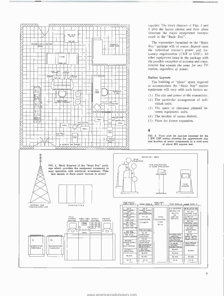
supplies. The block diagram of Figs. 3 and 6 plus the layout photos and floor plans illustrate the major equipments incorpo- rated in the "Basic Buy ".
The transmitter furnished in the "Basic Buy" package will, of course, depend upon the individual station's power and fre- quency requirements (UHF or VHF). All other equipment items in the package with the possible exception of antenna and trans- mission line remain the same for any TV station, regardless of power.
Station Layouts
The building or "plant" space required to accommodate the "Basic Buy" station equipment will vary with such factors as:
(1) (2)
(3)
(4) (5)
The size and power of the transmitter, The particular arrangement of indi- vidual units, The space or clearance planned be- tween equipment units, The number of rooms desired, Plans for future expansion.
FIG. 2. Floor plan (in one -foot squares) for the 1 KW UHF station showing the approximate size and location of major components in a total area
of about 900 square feet.
FIG. 3. Block diagram of the "Basic Buy" pack- age which provides the equipment necessary to start operation with minimum investment. (Note
that details of Rack panel layouts is given.)
ANTENNA AND 1551ON LINE
TRANSCRIPTION TURNTABLE
TRANSCRIPTION TURNTABLE
I 1 I
TRANSMITTER
FILM CAMERA AUDIO /VIDEO REMOTE PREVIEW CONTROL CONTROL CONTROL MONITOR
a PROJECTION ROOM
16 MM PROJECTORS
FILM MULTIPLEXER 1 SLIDE PROJECTOR
11 O 0 0000
O O ó ó ¡
Il .:. r
é°°ó II II I
VIDEO POWER SYNC.GEN. SUPPLY RACK 1 VIDEO RACK 2 RACK 5 TEST RACK AM)* RACK 5
56 -D POWER SUPPLY
FOR STAB. AMP.
56 -D POWER SUPPLY
FOR MONOSCOICCNA.
SYNC.
GENERATOR
TYPE TO-IA
FM MONITOR BW'OAL /AH
FOR VHF OR
13WU -6A FOR UHF.
BLAB METER PNi
BA -6A LIMITING AMP.
56 -D POWER SUPPLY
FOR STAB. AMP
TK -IS MONOSCOPE
CAMERA
A- BA -IIA PRE -AMPLIFIERS
WP -335 POWER SUPPLY I
FOR LINE pJl MASTER MONO
BA -ISA PROGRAM AMP.
O J O'0, R411 BA -MA
MONITORING AMP.
ADEDYOl PANEL W P- 13B
POWER SUPPLY FOR FILM
MASTER WHOOP
TA -5C STABILIZING AMPLIFIER
WF.50B FRED. MONITOR
135 -1E POWER SUPPLY BX -6A RELAY POWER SUPPLY TA -SC
STABILIZING AMPLIFIER
WE-40C FRED DEV METER
WP-33B POWER SUPPLY I
FOR FILM CAMERA
WM- 71A 015T0ß t NOISE U BM SOUND EOUILIZER WA- 3AGRATING
GENERATOR WA-25A
RJSMEUTTONOSC
SLAV It CURRENT REGULATOR
WA -21A VIDEO SWEEP
BLANK
BLANK BLANK
BLANK BLANK BLANK BLANK
57 -D 57 -O 57 -D 37 -D
9
www.americanradiohistory.com
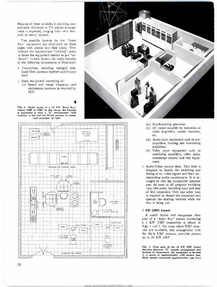
Because of these variables in planning, con- siderable difference in TV station arrange- ment is expected, ranging from very com- pact to roomy layouts.
Two possible layouts for the "Basic Buy" equipment are illustrated on these pages with photos and floor plans. They indicate the approximate "building" space to house the equipment needed to get "on- the- air ". In each layout, the major location of the following components is illustrated.
I. Transmitter, including vestigial side - band filter, antenna diplexer and dummy load.
2. Rack equipment consisting of: (a) Sound and visual frequency and
modulation monitors as required by FCC.
FIG. 4. Model layout of a 10 KW "Basic Buy" station (UHF or VHF). In this set -up, the Console is separated to form a "U" arrangement -with monitors at left and the TC -4A sections in center,
and turntables at right.
/I ,
/ / / /
I 300 LBS / N VESTIGIAL .- NNN NNN Im-- rORMERSÌ i SIOE BAD I
300 LBS IME FILTER NN M
NNNN NNNME 500 LBS.
1
1 N_Ì
I
TTUIOA
eaoo Ies NNN -/ I
NNTRANSMITTER
RL/0.0 010i0'
CONTROL ROOM /
nEMOTL CONTROL CONTROL
NN' %I N= Mill
1
N`f N NNNN 8 P aR ' .---- I : éá L TT. O _
i IN1 ® ANNOUNCE
J
I T STUDIO
II N __?-_ á
MONITOR
/ _TM2B . _.
uTIUTV MONITOR
Y ogR ,°
Ì
I-_- N MI PROJ. - -V MUL/TIPLE%ER
PROJ. Ira I' J 1 I
PROD.
-1--- I f1, PROJ. JIII
FILM PROJ. I rILM I
iAELITIC3 ' ü I-_ E I I-N J
N!. I
FILM
q'i.' n
*WEIGHTS ARE APPRO%, r 1
///// / / / / / / / / / / / / / / / / / / / / / / / / / / / / /// I 10
(b) Synchronizing generator. (c) DC power supplies for operation of
video amplifiers, master monitors, etc.
(d) Audio input equipment such as pre- amplifiers, limiting and monitoring amplifiers.
(e) Video input equipment such as stabilizing amplifiers, video jacks, monoscope camera and test equip- ment.
3. Audio -Video control desk. This desk is designed to handle the switching and fading of six video signals and their cor- responding audio counterparts. It is ar- ranged so that the transmitter operator may do most or all program switching from this point, including start and stop of film projectors. Only one other man is required to thread the projectors and operate the shading controls while the film is being run.
1 KW (UHF) Layout
A model layout and companion floor plan of a "Basic Buy" station employing a 1 KW UHF transmitter is shown in Figs. 1 and 2. For cities where UHF chan- nels are available, this arrangement with the RCA UHF antenna provides powers up to 20 KW ERP.
FIG. 5. Floor plan of the 10 KW UHF layout showing alternate "U" console arrangement and location of components. All equipment is located in a space of approximately 1100 square feet. (Each square represents approximately one loot.)
www.americanradiohistory.com
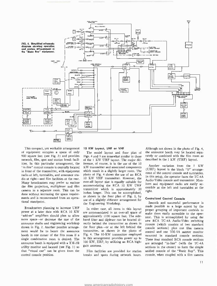
FIG. 6. Simplified schematic diagram showing operation and system arrangement of the "Basic Buy" equipment.
L
COM PO,
PVC VIDEO LOCK /
T PAR'
1LL
viDEO PROGRAM
ILIAVon
,LIGT[ >r-- °; L
SPARS >
S PO
MON
1.a1.)
" N.- D.
)sCo.. 17)
..>t 0.< t R
-1--
SUPPLY
AS 2
J4
SRO -0
CK01.°7:á.
CONTROL lWRt
This compact, yet workable arrangement of equipment occupies a space of only 900 square feet (see Fig. 2) and provides network, film, spot and station break facil- ities. In this particular arrangement, the "in- line" control console is centrally located in front of the transmitter, with equipment racks at left, turntables, and announce stu- dio at right -and film facilities at the rear. Many broadcasters may prefer to enclose the film projectors, multiplexer and film camera in a separate room. This can be done without increasing the space require- ments and is recommended from an opera- tional standpoint.
Broadcasters planning to increase UHF power at a later date with RCA 10 KW "add -on" amplifiers should plan to allow more space -or decrease the size of the announce studio and engineering workshop shown in Fig. 2. Another possible arrange- ment would be to locate the announce booth in one corner of the film room if a single combination room is desired. The announce booth is equipped with a TM -2B utility monitor and located (see Fig. 1) so that "visual cue" can be given from the control console position.
10 KW Layout, UHF or VHF
The model layout and floor plan of Figs. 4 and 5 are somewhat similar to those of the I KW UHF layout. The major dif- ference, of course, is in the use of the 10 KW transmitter and associated components which result in a slightly larger room. The photo of Fig. 4 shows the use of an RCA 10 KW VHF transmitter. However, the over -all layout size is equally suitable for accommodating the RCA 10 KW UHF transmitter which is approximately 30 inches longer. This can be accomplished, as shown in the floor plan of Fig. 5, by use of a slightly different arrangement for the Engineering Workshop.
In either case, all items in this layout are accommodated in an over -all space of approximately 1100 square feet. The side - band filter and diplexer can be located di- rectly behind the transmitter as shown in the floor plan -or at the left behind the transmitter, as shown in the photo of Fig. 4. The 10 -KW transmitter employed in this arrangement provides power up to 100 KW, ERP, by utilizing an RCA high - gain antenna.
Film facilities are provided for station breaks and spots during network hours.
TCHING
KoWL
Although not shown in the photo of Fig. 4, the announce booth may be located sepa- rately or combined with the film room as described in the 1 KW (UHF) layout.
Another variation from the 1 KW (UHF) layout is the block "U" arrange- ment of the control console and turntables. In this setup, the operator faces the TC -4A Audio /Video console and transmitter. Mon- itors and equipment racks are easily ac- cessible at the left and turntables at the right.
Centralized Control Console Smooth and successful performance is
made possible to a large extent by the proper grouping of important controls to make them easily accessible to the oper- ator. This is accomplished by using the new RCA TC -4A Audio -Video switching console (which consists of two standard console sections) plus one film camera control and one TM -5A master monitor mounted in standard console sections. These four standard RCA console sections are arranged "in- line" (with the TC -4A sections in the center) to form the simple unified console of the "Basic Buy ". This console, when coupled with a film camera
11
www.americanradiohistory.com
control, forms the nucleus of a complete television station operation, and may be used by small and large stations, as de- scribed later.
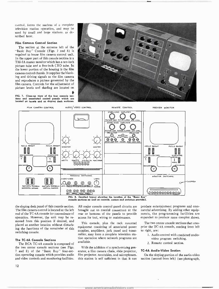
Film Camera Control Section
The section at the extreme left of the "Basic Buy" Console (Figs. 7 and 8) is required to house film camera control unit. In the upper part of this console section is a TM -5A master monitor which has a ten -inch picture tube and a five -inch CRO tube. In the lower portion of the housing is the film camera control chassis. It supplies the blank- ing and driving signals to the film camera and reproduces a picture generated by the film camera. Controls for the adjustment of picture levels and shading are located on
FIG. 7. Close -up view of the four console sec- tions and associated control panels which are located on turrets and on sloping desk surfaces.
FILM CAMERA CONTROL AUDIO VIDEO CONTROL REMOTE CONTROL PREVIEW MONITOR
STABILIZING AMPLIFIER
PIC*u0IN PI0I.DLRaut LC 1_ yi STABILIZING AMPLIFIER
SYNC PICT ®H
PICTtr®IPPER ®LEVEL
I I
-O -O I I
MONITOR MASTER
(_/ i(i , -\ / /; / / - -'` NV: RMONT2 ATOMIC CO CR PROJ SPARE
MONITOR SELECTOR
OOO ©O©
PROJECTOR PROJECTOR
O OFD QO ON \V \J
STAND BV SLIDE PROD. ST By
ST000 P cAOF START 00®
FOCUS
OSCILLOSCOPE
BRIGHT FOCUS
PHESCOPE
BRIGHT I
JSC
L
ox Ll0
5
LLO
BFIGhi Fr ^E
CLEF 'INE.
H
L LPL
o '
CAL
1 OKALOMO
ve
LOSLOPL
I¢, , I
,NOR 2L
C 0 - PROGRAM SWITCHING
AUDIO -VIDEO VIDEO
,H o. o©© O
MONITOR SWITCHING
r" [D 0) lD U J J SAWTOOTH PARABOLA SAWTOOTH PARABOLA
H0RITOHTAL SHARING VERTICAL SHADING LOCK 2-3-103 L- -y 1=130 I FADER
OO 0 O© OOO T= =O= I
VOOOOVOOO©OO) FIG. 8. Detailed layout showing the location of the "Basic Buy" console sections as well as controls, meters and switches provided.
the sloping desk panel of this console section. The film camera control is located at the left end of the TC -4A console for convenience of operation. However, the unit may be re- moved from this position if desired, and placed at another location without disturb- ing the functions of the remainder of this switching console.
The TC-4A Console Sections The RCA TC -4A console is composed of
the two center console sections (see Figs. 7 and 8) of the "Basic Buy" four -sec- tion operating console which provides audio and video controls and monitoring facilities.
12
All major console control panel circuits are brought out to coaxial connectors at the rear or bottoms of the panels to provide access for test, wiring or maintenance.
This console, plus the rack mounted equipment consisting of associated power supplies, amplifiers, jack panel and trans- mitter, may form a complete television sta- tion operation where network programs are available.
With the addition of a synchronizing gen- erator, a film camera chain, slide projector, film projector, turntables, and microphones, this station is self sufficient in that it can
CHOPPER
produce entertainment programs and com- mercial advertising. By adding other equip- ments, the programming facilities are expanded to produce more complex shows.
The two center console sections that com- prise the TC -4A console, reading from left to right, are:
1. Audio control with combined audio - video program switching.
2. Remote control section.
TC -4A Audio -Video Section
On the sloping portion of the audio -video section (second from left) (see photograph,
www.americanradiohistory.com
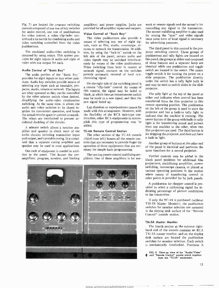
Fig. 7) are located the program switching controls composed of one row of key switches for audio control, one row of pushbuttons for video control, a video clip -fader con- trol and a tie switch for combining audio and video switching controlled from the video pushbuttons.
The combined audio -video switching is obtained by using relays. This system pro- vides for eight inputs of audio and eight of video with one output for each.
Audio Control of "Basic Buy" The audio portion of the "Basic Buy"
provides for eight inputs to four mixer posi- tions. Audio key switches provide means of selecting any input such as turntable, pro- jector, studio, remote or network. The inputs are relay operated so they can be controlled by the video selector switch when desired, simplifying the audio -video combination switching. At the same time. it allows the audio and video switches to be closed to- gether for convenient operation, and keeps the actual circuits apart to prevent crosstalk. The relays are interlocked to prevent ac- cidental doubling of the circuits.
A selector switch allows a monitor am- plifier and speaker to check most of the audio circuits including transmitter input and output, and turntable cueing. It is visual- ized that a separate cueing amplifier and speaker may be used in most applications.
One rack of equipment is needed in addi- tion to the panel. This houses the pre- amplifiers; program, monitor, and limiting
amplifiers; and power supplies. Jacks are provided for all amplifier inputs and outputs.
Video Control of "Basic Buy" The video pushbuttons also provide a
means of selecting any one of eight sig- nals, such as film, studio. monoscope, re- motes or network for transmission. In addi- tion, by using the "lock -in" switch on the left side of the panel, certain audio and video signals may be switched simultane- ously by means of the video pushbuttons. When switching from local to remote or network signal, contacts on the switches provide automatic removal of local syn- chronizing signal.
On the right side of the switching panel is a remote "clip- fade" control. By means of this control, the signal may be faded to black, at which time an instantaneous switch may be made to a new signal, and then the new signal faded up.
Lap dissolves or superpositions cannot be made with this arrangement. However, with the flexibility of the RCA unit -type con- struction, other RCA equipments to accom- plish this type of programming may be added.
TC -4A Remote Control Section The other section of the TC -4A console
(third from left) houses all the remote con- trols that are necessary to provide finger tip operation of those equipments that are nec- essary for simple basic programming.
The two top panels control stabilizing am- plifiers. One of these amplifiers is for net-
work or remote signals and the second is for controlling any signal to the transmitter. The second stabilizing amplifier is also used for mixing the "sync" and video signals since some form of local signal is necessary for advertising purposes.
The third panel in this control is the pro- jector switching control. Three groups of pushbuttons and tally lights are located on this panel, the groups at either end composed of three buttons and a separate lamp are identical while one pushbutton and toggle switch are located in the center. The center toggle switch is for turning the power on a slide projector. The pushbutton directly under the switch has a tally light built in and may be used to switch slides in the slide projector.
The tally light at the top of the panel at either end indicates when control has been transferred from the film projector to this remote operating position. The pushbutton on the left of the group is used to start the projector and has a built -in tally light to indicate that the machine is running. The center button of the group with built -in tally light is for transferring sound and picture from one machine to the other, when two film projectors are used. The third button is for stopping the projector, and does not have a built -in light.
Another group of buttons at the other end of the panel is identical and performs the same functions for a second projector.
Further controls may be added in the blank panel positions for additional film projectors, stabilizing amplifier, power switching, monoscope camera, or placed at various operating positions in the station where means of transferring control to other points is provided for by jack panels.
A pushbutton for chopper control is pro- vided to select a calibrating signal for in- dicating percentage of picture modulation to the transmitter.
If only the TC -4A is purchased (without TM -5B Master Monitor), the pushbutton switches for monitor selection are mounted in the sloping desk surface of the "Remote Control" console section.
TM -5A Master Monitor The fourth section at the extreme right -
hand end of the console contains an RCA TM -5A master monitor, and on the sloping desk surface are located the pushbutton switches for monitor selection. Each switch is mechanically interlocked. Provision is
FIG. 9. Close up view of the "Audio /Video" and "Remote Control" panels which together
form the "TC -4A'" equipment.
13
www.americanradiohistory.com
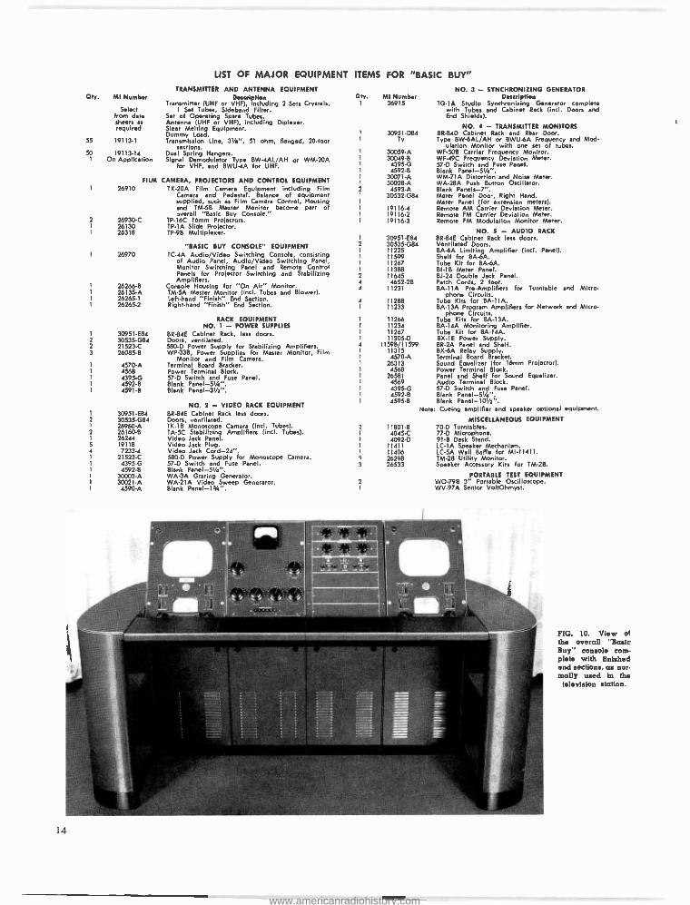
LIST OF MAJOR EQUIPMENT
TRANSMITTER AND ANTENNA EQUIPMENT Qty. MI Number Description
Transmitter (UHF or VHF), including 2 Sets Crystals, Select 1 Set Tubes, Sideband Filter.
from data Set of Operating Spare Tubes. sheets as Antenna (UHF or VHF), including Diplexer. required Sleet Melting Equipment.
Dummy Load. 55 19113 -1 Transmission Line, 31/8 ", 51 ohm, Flanged, 20 -foot
sections. 50 19113.14 Dual Spring Hangers.
1 On Application Signal Demodulator Type BW- 4AL /AH or WM -20A for VHF, and BWU -4A for UHF.
FILM CAMERA, PROJECTORS AND CONTROL EQUIPMENT 26910 TK -20A Film Camera Equipment including Film
Camera and Pedestal. Balance of equipment supplied, such as Film Camera Control, Housing and TM -58 Master Monitor become part of overall "Basic Buy Console."
2 26930 -C TP -16C 16mm Projectors. 1 26130 TP -lA Slide Projector. I 26318 TP -9B Multiplexer.
"BASIC BUY CONSOLE" EQUIPMENT 26970 TC -4A Audio /Video Switching Console, consisting
of Audio Panel, Audio /Video Switching Panel, Monitor Switching Panel and Remote Control Panels for Projector Switching and Stabilizing Amplifiers.
26266 -B Console Housing for "On Air" Monitor. 26135 -A TM -5A Master Monitor (incl. Tubes and Blower). 26265 -1 Left-hand "Finish" End Section. 26265 -2 Right -hand "Finish" End Section.
RACK EQUIPMENT NO. 1 - POWER SUPPLIES
1 30951 -E84 BR -84E Cabinet Rack, less doors. 2 30535 -G84 Doors, ventilated. 2 21523 -C 580 -D Power Supply for Stabilizing Amplifiers. 3 26085.8 WP -33B, Power Supplies for Master Monitor, Film
Monitor and Film Camera. 1 4570 -A Terminal Board Bracket.
4568 Power Terminal Block. I 4395 -G 57 -D Switch and Fuse Panel.
4592 -B Blank Panel- 51/4 ". 4591 -B Blank Panel- 31 /z ".
1
2 1
2
5 4
30951 -E84 30535 -G84 26960 -A 26160 -B 26244 19118 7233 -4
21523 -C 4395 -G 4592 -B
30003 -A 30021 -A
4590 -A
NO. 2 - VIDEO RACK EQUIPMENT BR-84E Cabinet Rack less doors. Doors, ventilated. TK -1B Monoscope Camera (incl. Tubes). TA -5C Stabilizing Amplifiers (incl. Tubes). Video Jack Panel. Video Jack Plug. Video Jack Cord -24 ". 580 -D Power Supply for Monostola Camera. 57 -D Switch and Fuse Panel. Blank Panel- 51 /a ". WA -3A Grating Generator. WA -21A Video Sweep Generator. Blank Panel -13A ".
ITEMS FOR "BASIC BUY"
Cty MI Number 26915
1
2
1
1
1
2
4
4
4
n
3
2
NO. 3 - SYNCHRONIZING GENERATOR Description
TG -1A Studio Synchronizing Generator complete with Tubes and Cabinet Rack (incl. Doors and End Shields).
NO. 4 - TRANSMITTER MONITORS 30951.084 BR -84D Cabinet Rack and Rear Door.
Ty Type BW-6AL /AH or BWUÓA Frequency and Mod- ulation Monitor with one set of tubes.
30059 -A WF -50B Carrier Frequency Monitor. 30049 -8 WF -49C Frequency Deviation Meter.
4395 -G 57 -D Switch and Fuse Panel. 4592 -B Blank Panel- 51/4 ".
30071 -A WM -71A Distortion and Noise Meter. 30028 -A WA -28A Push Button Oscillator.
4593 -A Blank Panels -7 ". 30532 -G84 Meter Panel Door, Right Hand.
Meter Panel (for extension meters). 19116.4 Remote AM Carrier Deviation Meter. 19116.2 Remote FM Carrier Deviation Meter. 19116 -3 Remote FM Modulation Monitor Meter.
NO. S - AUDIO RACK 30951 -E84 BR -84E Cabinet Rack less doors. 30535 -G84 Ventilated Doors. 11225 BA-6A Limiting Amplifier (incl. Panel). 11599 Shelf for BA-6A. 11267 Tube Kit for BA-6A. 11388 BI -1B Meter Panel. 11645 EU-24 Double Jack Panel.
4652 -2B Patch Cords, 2 foot. 11231 BA -I IA Pre -Amplifiers for Turntable and Micro-
phone Circuits. 11288 Tube Kits for 8A -11A. 11233 BA -13A Program Amplifiers for Network and
phone Circuits. 11266 Tube Kits for BA -I3A. 11234 8A -14A Monitoring Amplifier. 11267 Tube Kit for BA -14A. 11305 -D BX -IE Power Supply.
11598/11599 BR -2A Panel and Shelf. 11315 BXLA Relay Supply. 4570 -A Terminal Board Bracket.
26313 Sound Equalizer (for 16mm Projector). 4568 Power Terminal Block.
26581 Panel and Shelf for Sound Equalizer. 4569 Audio Terminal Block. 4395 -G 57 -D Switch and Fuse Panel. 4592 -8 Blank Panel- 51/4 ". 4595 -8 Blank Panel -101 ".
Note: Cueing amplifier and speaker optional equ
MISCELLANEOUS EQUIPMENT 11801 -B 70 -D Turntables. 4045 -C 77 -0 Microphone. 4092 -D 91 -B Desk Stand.
11411 LC -1A Speaker Mechanism. 11406 LC -5A Wall Baffle for MI- 11411. 26298 TM -2B Utility Monitor. 26533 Speaker Accessory Kits for TM -2B.
PORTABLE TEST EQUIPMENT WO -79B 3" Portable Oscilloscope. WV -97A Senior VoltOhmyst.
14
Micro-
ipment.
FIG. 10. View of the overall ' "Basic Buy "" console corn - plete with finished end sections, as nor. malty used in the
television station.
www.americanradiohistory.com
made for twelve inputs and one output. This unit may be used to monitor all the necessary transmitter signals in addition to serving as a preview monitor for remotes and networks. In the normal position, this monitor will register the line signal.
"One -Man" Operation Possible
With the arrangement shown, the "Basic Buy" console could easily be operated by one man. All of the necessary controls for programming are centralized in the 4- section "Basic Buy" console except the audio and video jack panels which are located in nearby equipment racks.
Even with the addition of one or two film camera controls, it would also be possible for one person to handle both network and film programs. However, many stations will prefer to use two operators, and two are easily accommodated with the proposed arrangements.
Application Flexibility Inspection of the block diagram (see
Fig. 6) makes it apparent that this con- sole or any section of it may be used for various purposes at locations remote from the transmitter. For example, the preview monitor and audio console could be used in a studio control room or remote position along with the other video equipment.
Similarly, the remote control section could be used in a studio control room or master control.
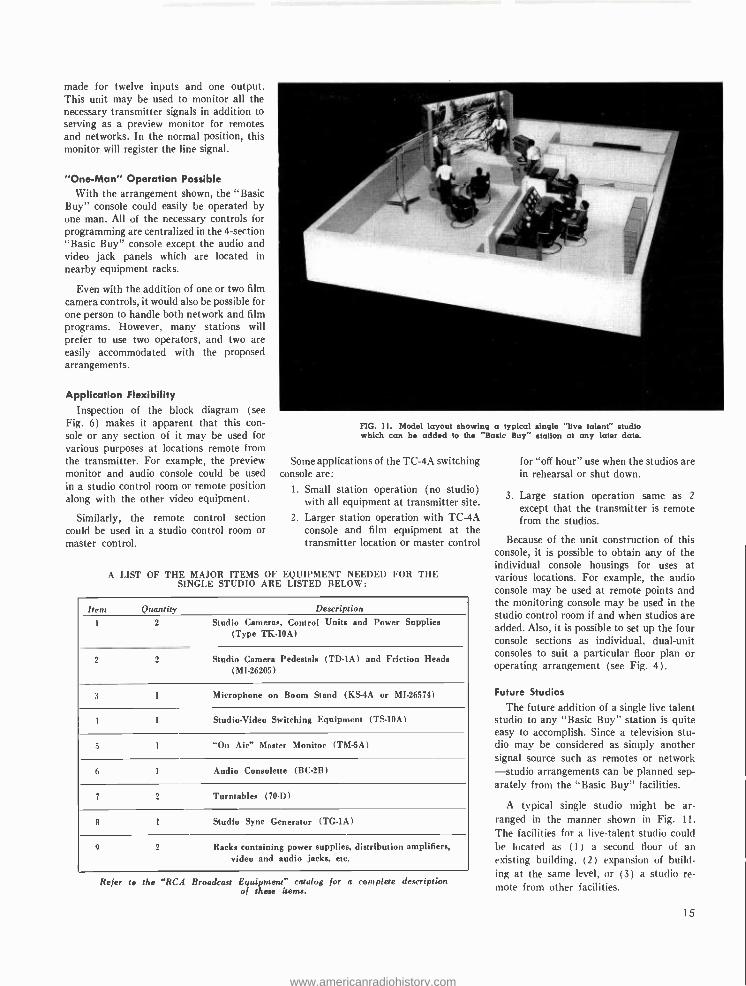
FIG. 11. Model layout showing a typical single "live talent" studio which can be added to the 'Basic Buy" station at any later date.
Some applications of the TC -4A switching console are:
I. Small station operation (no studio) with all equipment at transmitter site.
2. Larger station operation with TC -4A console and film equipment at the transmitter location or master control
A LIST OF THE MAJOR ITEMS OF EQUIPMENT NEEDED FOR THE SINGLE STUDIO ARE LISTED BELOW:
Item Quantity Description
1 2 Studio Cameras, Control Units and Power Supplies (Type TK -10A)
2 Studio Camera Pedestals (TD -1A) and Friction Heads (MI. 26205)
3 1 Microphone on Boom Stand (KS-4A or MI- 26574)
I 1 Studio -Video Switching Equipment (TS -10A)
5 1 "On Air" Master Monitor (TM -5A)
6 1 Audio Consolette (BC -2B)
7 2 Turntables (70 -D)
8 1 Studio Sync Generator (TG -1A)
9 2 Racks containing power supplies, distribution amplifiers, video and audio jacks, etc.
Refer to the "RCA Broadcast Equipment" catalog for a complete description of these items.
for "off hour" use when the studios are in rehearsal or shut down.
3. Large station operation same as 2
except that the transmitter is remote from the studios.
Because of the unit construction of this console, it is possible to obtain any of the individual console housings for uses at various locations. For example, the audio console may be used at remote points and the monitoring console may be used in the studio control room if and when studios are added. Also, it is possible to set up the four console sections as individual, dual -unit consoles to suit a particular floor plan or operating arrangement (see Fig. 4).
Future Studios
The future addition of a single live talent studio to any "Basic Buy" station is quite easy to accomplish. Since a television stu- dio may be considered as simply another signal source such as remotes or network -studio arrangements can be planned sep- arately from the "Basic Buy" facilities.
A typical single studio might be ar- ranged in the manner shown in Fig. 11.
The facilities for a live -talent studio could be located as ( 1 ) a second floor of an existing building, (2 ) expansion of build- ing at the same level, or (3) a studio re- mote from other facilities.
15
www.americanradiohistory.com
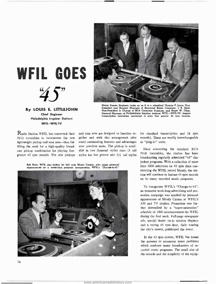
WFIL GOES
4S" By LOUIS E. LITTLEJOHN
Chief Engineer Philadelphia Inquirer Stations
WFIL -WFIL -TV
Radio Station WFIL has converted their 70 -D turntables to incorporate the new
lightweight pickup and tone arm -thus ful-
filling the need for a high -quality broad- cast pickup combination for playing fine -
groove 45 rpm records. The new pickups
Meyer Posner, Engineer, looks on as (1. to r., standing) Thomas F. Joyce, Vice - President and General Manager of Raymond Rosen Company, J. B. Eliott, Vice- President in Charge of RCA Consumer Products, and Roger W. Clipp. General Manager of Philadelphia Inquirer stations WFIL- WFIL -TV. inspect transcription turntables converted to play line groove 45 rpm records.
and tone arm are designed to function to- gether and with this arrangement offer
many outstanding features and advantages over previous units. The pickup is avail- able in two diamond stylus sizes (1 mil
stylus for fine groove and 2% mil stylus
Bob Horn, WFIL disc jockey (at left) with Mindy Carson, who made personal appearances on a week -long program inaugurating WFIL's "Change- to -45."
16
for standard transcription and 78 rpm
records). These are readily interchangeable as "plug -in" units.
Since converting the standard RCA 70 -D turntables, the station has been broadcasting regularly scheduled "45" disc jockey programs. With a collection of more than 5000 selections on 45 rpm discs con- stituting the WFIL record library, the sta- tion will continue to feature 45 rpm records on its many recorded music programs.
To inaugurate WFIL's "Change- to -45 ". an intensive week -long advertising and pro- motion campaign was sparked by personal appearances of Mindy Carson at WFIL's AM and TV studios. Promotion was fur-
ther intensified by a "super- saturation" schedule of 1000 announcements by WFIL during the first week. Full -page newspaper ads, special dealer tie -in window displays and a roving 45 rpm float, daily touring the city's streets, publicized the event.
In the 45 rpm system, WFIL has found
the answers to numerous space problems which confront many broadcasters of re-
corded music programs. The small size of
the records and the simplicity of the equip-
www.americanradiohistory.com
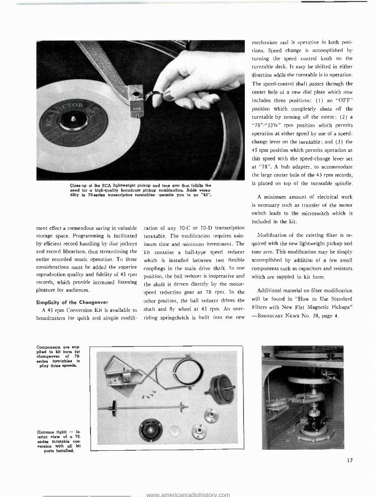
Close -up of the RCA lightweight pickup and tone arm that fulfills the need for a high- quality broadcast pickup combination. Adds versa- tility to 70- series transcription turntables- permits you to go " "45"".
ment effect a tremendous saving in valuable storage space. Programming is facilitated by efficient record handling by disc jockeys
and record librarians, thus streamlining the
entire recorded music operation. To these
considerations must be added the superior reproduction quality and fidelity of 45 rpm
records, which provide increased listening
pleasure for audiences.
Simplicity of the Changeover
A 45 rpm Conversion Kit is available to
broadcasters for quick and simple modifi-
Components are sup- plied in kit form for changeover of 70- series turntables to
play three speeds.
(Extreme right) -- In-
terior view of a 70. series turntable con- version with all kit
parts installed.
cation of any 70 -C or 70 -D transcription
turntable. The modification requires min-
imum time and minimum investment. The
kit contains a ball -type speed reducer
which is installed between two flexible
couplings in the main drive shaft. In one
position, the ball reducer is inoperative and
the shaft is driven directly by the motor -
speed reduction gear at 78 rpm. In the
other position, the ball reducer drives the
shaft and fly wheel at 45 rpm. An over-
riding springclutch is built into the new
mechanism and is operative in both posi-
tions. Speed change is accomplished by
turning the speed control knob on the
turntable deck. It may be shifted in either
direction while the turntable is in operation.
The speed- control shaft passes through the
center hole of a new dial plate which now
includes three positions: (1) an "OFF" position which completely shuts off the
turntable by turning off the motor; (2) a
"78 "- "331/3" rpm position which permits
operation at either speed by use of a speed -
change lever on the turntable; and (3) the
45 rpm position which permits operation at
this speed with the speed- change lever set
at "78 ". A hub adapter, to accommodate
the large center hole of the 45 rpm records,
is placed on top of the turntable spindle.
A minimum amount of electrical work
is necessary such as transfer of the motor
switch leads to the microswitch which is
included in the kit.
Modification of the existing filter is re-
quired with the new lightweight pickup and
tone arm. This modification may be simply
accomplished by addition of a few small
components such as capacitors and resistors
which are suppled in kit form.
Additional material on filter modification
will be found in "How to Use Standard
Filters with New Flat Magnetic Pickups"
-BROADCAST NEWS No. 58, page 4.
17
www.americanradiohistory.com
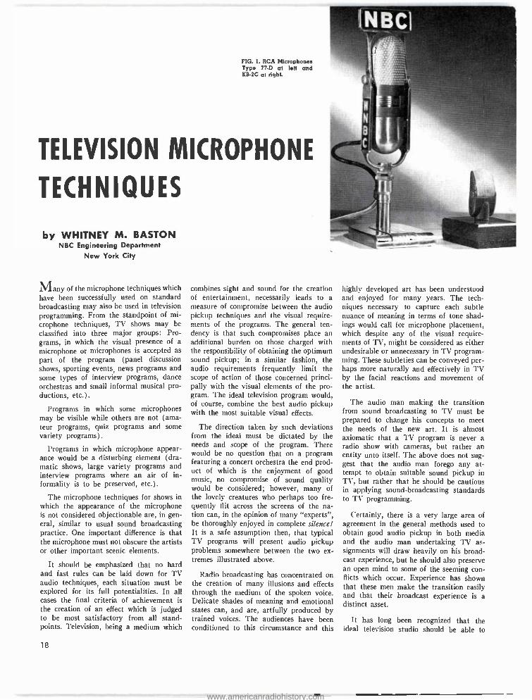
FIG. L RCA Microphones Type 77 -D at left and KB -2C at right.
TELEVISION MICROPHONE
TECHNIQUES
by WHITNEY M. BASTON NBC Engineering Department
New York City
Many of the microphone techniques which have been successfully used on standard broadcasting may also be used in television programming. From the standpoint of mi- crophone techniques, TV shows may be classified into three major groups: Pro- grams, in which the visual presence of a microphone or microphones is accepted as part of the program (panel discussion shows, sporting events, news programs and some types of interview programs, dance orchestras and small informal musical pro- ductions, etc.).
Programs in which some microphones may be visible while others are not (ama- teur programs, quiz programs and some variety programs).
Programs in which microphone appear- ance would be a disturbing element (dra- matic shows, large variety programs and interview programs where an air of in- formality is to be preserved, etc.).
The microphone techniques for shows in which the appearance of the microphone is not considered objectionable are, in gen- eral, similar to usual sound broadcasting practice. One important difference is that the microphone must not obscure the artists or other important scenic elements.
It should be emphasized that no hard and fast rules can be laid down for TV audio techniques, each situation must be explored for its full potentialities. In all cases the final criteria of achievement is the creation of an effect which is judged to be most satisfactory from all stand- points. Television, being a medium which
18
combines sight and sound for the creation of entertainment, necessarily leads to a measure of compromise between the audio pickup techniques and the visual require- ments of the programs. The general ten- dency is that such compromises place an additional burden on those charged with the responsibility of obtaining the optimum sound pickup; in a similar fashion, the audio requirements frequently limit the scope of action of those concerned princi- pally with the visual elements of the pro- gram. The ideal television program would, of course, combine the best audio pickup with the most suitable visual effects.
The direction taken by such deviations from the ideal must be dictated by the needs and scope of the program. There would be no question that on a program featuring a concert orchestra the end prod- uct of which is the enjoyment of good music, no compromise of sound quality would be considered; however, many of the lovely creatures who perhaps too fre- quently flit across the screens of the na- tion can, in the opinion of many "experts ", be thoroughly enjoyed in complete silence! It is a safe assumption then, that typical TV programs will present audio pickup problems somewhere between the two ex- tremes illustrated above.
Radio broadcasting has concentrated on the creation of many illusions and effects through the medium of the spoken voice. Delicate shades of meaning and emotional states can, and are, artfully produced by trained voices. The audiences have been conditioned to this circumstance and this
highly developed art has been understood and enjoyed for many years. The tech- niques necessary to capture each subtle nuance of meaning in terms of tone shad- ings would call for microphone placement, which despite any of the visual require- ments of TV, might be considered as either undesirable or unnecessary in TV program- ming. These subtleties can be conveyed per- haps more naturally and effectively in TV by the facial reactions and movement of the artist.
The audio man making the transition from sound broadcasting to TV must be prepared to change his concepts to meet the needs of the new art. It is almost axiomatic that a TV program is never a radio show with cameras, but rather an entity unto itself. The above does not sug- gest that the audio man forego any at- tempt to obtain suitable sound pickup in TV, but rather that he should be cautious in applying sound -broadcasting standards to TV programming.
Certainly, there is a very large area of agreement in the general methods used to obtain good audio pickup in both media and the audio man undertaking TV as- signments will draw heavily on his broad- cast experience, but he should also preserve an open mind to some of the seeming con- flicts which occur. Experience has shown that these men make the transition easily and that their broadcast experience is a distinct asset.
It has long been recognized that the ideal television studio should be able to
www.americanradiohistory.com
provide many different acoustic conditions varying from outdoor scenes to interiors of
large halls and small living rooms. The current practice in most instances is to keep the actual reverberation character- istic of the studio as low as possible. The reverberant effect furthermore helps to muffle to some extent the background noise from off- the -set activities. Liveness can then be gained by the addition of hard flats which constitute the scenery. sacri- ficing weight but retaining high frequency reflections. The rather wide use of sets having hard surfaces frequently alters the acoustic characteristics in the microphone pickup area and suitable adjustments must be made in microphone placement. Some- times acoustic absorbent flats are used as a band shell and enclosure to isolate an orchestra from the cast when both groups are functioning within the same television studio.
The types of microphones currently in
use in television range from the familiar broadcast types, such as the 77 -D, 44 -BX, 88 -A, to the new small models like the KB -2C and the new pencil type micro- phone exemplified by the "Starmaker."
The problem of sound pickup on TV programs includes many considerations not present in sound broadcasting. One of the most important points that must be con- sidered is that of unwanted noise which is
the natural result of motion of the actors, cameras, microphone boom, scenery, etc., all necessary to the show, but collectively a source of noise which must be minimized if a successful sound pickup is to result.
A convenient concept is to consider the existence of an imaginary line drawn be- tween the scene of action and the camera. With this division, it will be found that a
large majority of the unwanted noise will originate on the camera side of the line and almost all of the desired sounds from the particular scene will originate on the other side of the line. Such a set of circumstances suggests the use of a uni- directional micro- phone, such as obtainable with the RCA 77 -D. A consideration of typical TV scenes would suggest that the imaginary line re- ferred to above would shift from scene to scene, it is obvious then that the micro- phone must be movable. The boom pro- vides the answer to this problem; typical boom microphones are arranged so that from one position of the boom the micro- phone can be moved a distance of 10 feet and can swing in an arc of 280° with ad- justable radius from 7 to 17 feet. In addi- tion to the horizontal motion, the micro- phone can be raised and lowered above and below the horizontal. The microphone is
thus capable of occupying various positions in a rather large solid angle.
Approaching the ambient noise problem from a somewhat different point of view the signal to noise ratio at the microphone is determined by the ratio which exists be- tween the direct or desired sound and the unwanted sound. It is obvious that an in- crease in the direct sound level will be desirable. This can be done by following the action with the boom microphone so that the distance between the performer and the microphone where desirable is kept reasonably constant at perhaps 3 feet or slightly more. The directional pattern most frequently used in TV is the uni- directional pattern; however, many uses exist for bi- directional and spherical pickup patterns. Examples of typical program setups given later will show uses for the several patterns. In the foregoing somewhat over -simplified explanation of the use of the boom micro- phone, no mention was made of some of th' practical day to day problems which arise.
The usual use of a boom microphone is for scenes in which the microphone should not be seen by the television audience. The scenes taken by the TV camera will range from closeup to wide angle shots, so that a boom microphone positioned for good sound pickup on a closeup would be in the picture on a medium or wide angle shot. In usual studio practice the audio engineer or mixer previews the picture on a TV monitor and talks to the boom oper- ator over the inter- communication system advising him of the position of his micro- phone and warning him if there is danger of the microphone showing in the picture. If such a danger should be present, and
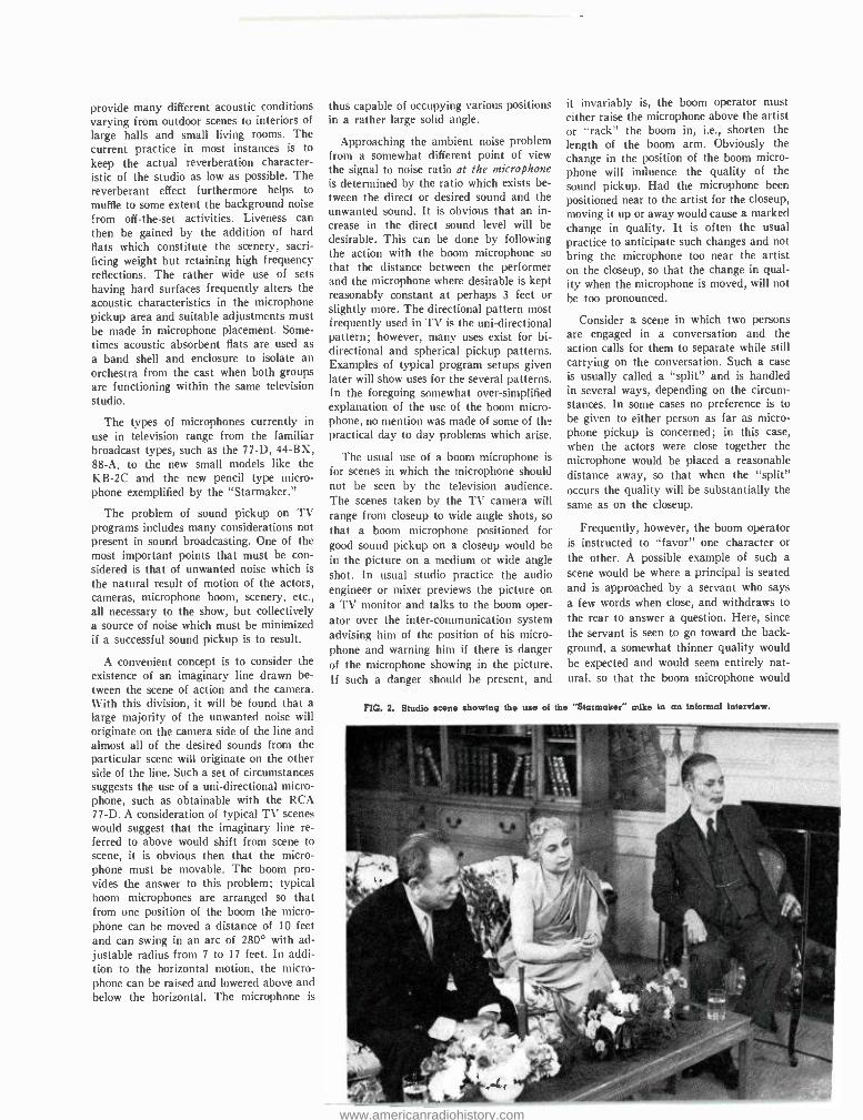
FIG. 2. Studio scene showing the use of
it invariably is, the boom operator must either raise the microphone above the artist or "rack" the boom in, i.e., shorten the length of the boom arm. Obviously the change in the position of the boom micro- phone will influence the quality of the sound pickup. Had the microphone been positioned near to the artist for the closeup, moving it up or away would cause a marked change in quality. It is often the usual practice to anticipate such changes and not bring the microphone too near the artist on the closeup, so that the change in qual- ity when the microphone is moved, will not be too pronounced.
Consider a scene in which two persons are engaged in a conversation and the action calls for them to separate while still carrying on the conversation. Such a case is usually called a "split" and is handled in several ways, depending on the circum- stances. In some cases no preference is to be given to either person as far as micro- phone pickup is concerned; in this case, when the actors were close together the microphone would be placed a reasonable distance away, so that when the "split" occurs the quality will be substantially the same as on the closeup.
Frequently, however, the boom operator is instructed to "favor" one character or the other. A possible example of such a scene would be where a principal is seated and is approached by a servant who says a few words when close, and withdraws to the rear to answer a question. Here, since the servant is seen to go toward the back- ground, a somewhat thinner quality would be expected and would seem entirely nat- ural, so that the boom microphone would
the "Starmakef' mike in an informal interview.
www.americanradiohistory.com
not necessarily follow the servant. Other examples are combinations involving a strong male voice and a rather thin female voice, usually in such cases the weaker voice is favored. In many instances one actor may be seated and another standing so that the distance from the microphone to each actor must be adjusted by select- ing a suitable compromise position. It is obvious that one microphone cannot be expected to take care of all situations; in some instances concealed microphones are used to pick up one or more of the voices.
Where several microphones are required great care should be exercised in selecting microphones of similar effective frequency response characteristics to that of the boom microphone to avoid a noticeable change in sound quality in going from one micro- phone to the other. It is also important that such changes be kept to an absolute minimum because in most cases concealed microphones are placed in close proximity to a variety of surfaces or objects which lead to serious wave interferences and un- desirable phasing effects.
Recently, great strides have been made in developing unobtrusive microphones which are small enough to be hardly notice- able if carefully blended in with the sur- roundings without sacrificing the acoustical properties of these transducers (Fig. 1). Because of the bi- directional pattern of the RCA KB -2C, some care must be exercised in its use, but if the ratio of direct sound to reflected sound is large enough, this microphone can be used to excellent ad- vantage. For close talking purposes this
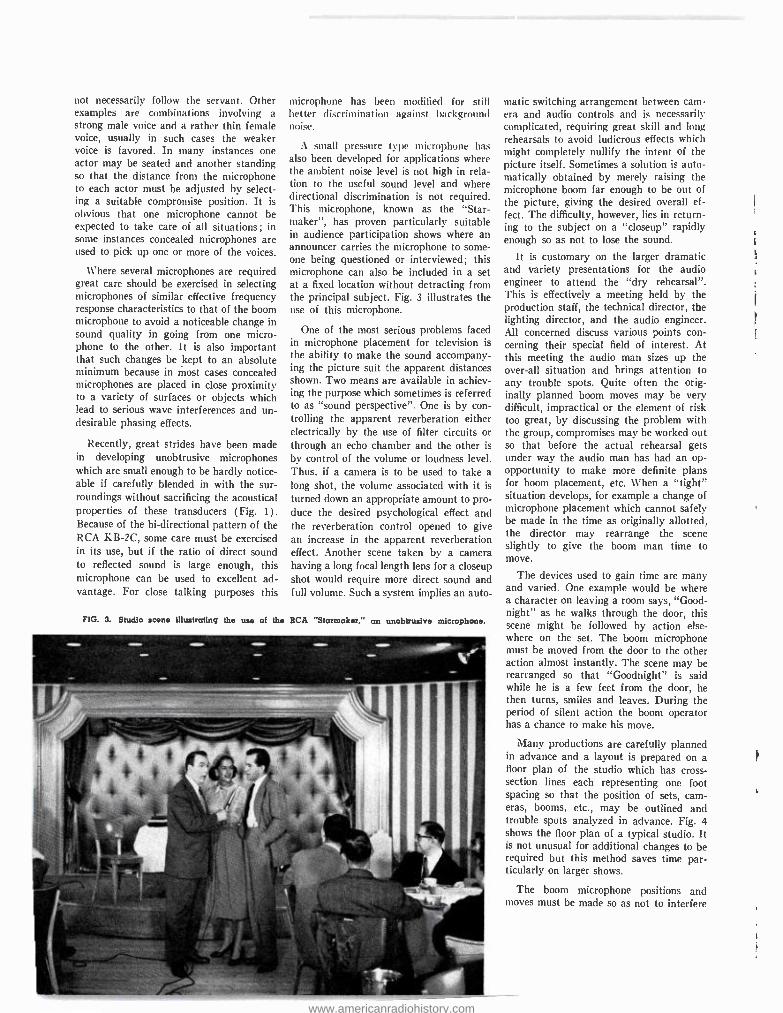
FIG. 3. Studio
microphone has been modified for still better discrimination against background noise.
A small pressure type microphone has also been developed for applications where the ambient noise level is not high in rela- tion to the useful sound level and where directional discrimination is not required. This microphone, known as the "Star - maker", has proven particularly suitable in audience participation shows where an announcer carries the microphone to some- one being questioned or interviewed; this microphone can also be included in a set at a fixed location without detracting from the principal subject. Fig. 3 illustrates the use of this microphone.
One of the most serious problems faced in microphone placement for television is the ability to make the sound accompany- ing the picture suit the apparent distances shown. Two means are available in achiev- ing the purpose which sometimes is referred to as "sound perspective ". One is by con- trolling the apparent reverberation either electrically by the use of filter circuits or through an echo chamber and the other is
by control of the volume or loudness level. Thus, if a camera is to be used to take a long shot, the volume associated with it is
turned down an appropriate amount to pro- duce the desired psychological effect and the reverberation control opened to give an increase in the apparent reverberation effect. Another scene taken by a camera having a long focal length lens for a closeup shot would require more direct sound and full volume. Such a system implies an auto-
scene Illustrating the use of the RCA "Starmaker," an unobtrusive microphone.
matie switching arrangement between cam- era and audio controls and is necessarily complicated, requiring great skill and long rehearsals to avoid ludicrous effects which might completely nullify the intent of the picture itself. Sometimes a solution is auto- matically obtained by merely raising the microphone boom far enough to be out of the picture, giving the desired overall ef- fect. The difficulty, however, lies in return- ing to the subject on a "closeup" rapidly enough so as not to lose the sound.
It is customary on the larger dramatic and variety presentations for the audio engineer to attend the "dry rehearsal ". This is effectively a meeting held by the production staff, the technical director, the lighting director, and the audio engineer. All concerned discuss various points con- cerning their special field of interest. At this meeting the audio man sizes up the over -all situation and brings attention to any trouble spots. Quite often the orig- inally planned boom moves may be very difficult, impractical or the element of risk too great, by discussing the problem with the group, compromises may be worked out so that before the actual rehearsal gets under way the audio man has had an op- opportunity to make more definite plans for boom placement, etc. When a "tight" situation develops, for example a change of microphone placement which cannot safely be made in the time as originally allotted, the director may rearrange the scene slightly to give the boom man time to move.
The devices used to gain time are many and varied. One example would be where a character on leaving a room says, "Good- night" as he walks through the door, this scene might be followed by action else- where on the set. The boom microphone must be moved from the door to the other action almost instantly. The scene may be rearranged so that "Goodnight" is said while he is a few feet from the door, he then turns, smiles and leaves. During the period of silent action the boom operator has a chance to make his move.
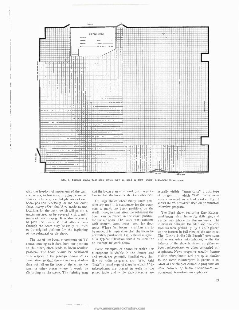
Many productions are carefully planned in advance and a layout is prepared on a floor plan of the studio which has cross - section lines each representing one foot spacing so that the position of sets, cam- eras, booms, etc., may be outlined and trouble spots analyzed in advance. Fig. 4 shows the floor plan of a typical studio. It is not unusual for additional changes to be required but this method saves time par- ticularly on larger shows.
The boom microphone positions and moves must be made so as not to interfere
www.americanradiohistory.com
I {
i ............1 i. H H... n ..MI
CONTROL ROOM
I.:Mi :. _. /...1 I ................ um . . /././1 IMMH.M . M.. EOM .nMn MM/. i :. i n: ....1 aonu. I..nYM./ Elm . . i;::/.//......1 .. a.. . .......................:/ .. .i... ..::. ....... .1 .c,,,c. IMMMU//.//M .. .. M. .:HI nrna
- H H/ MM..M.M.1 a a.a iH Hp imam . MnN.1 I.Y: :W:.:.: :::::::::::::úi ..*i::::i::::::i:°::C...n ..1 - WHHY.YW M.M.MM :::°:::::::YYS:i..MM.iï:iiii::::::::::::°M:pi::::i::::::.
:/:::::::' ::C: ::CC::: ::::::E:Ï EÇ=:?:::::::::: ::°:Ç=
:::.:....I ../......................M..1 ......M1 :°/::::::::ii::::::::::::::: i:°::::::::::::iii::::i::: °::: :'.':::::::'M::'.:C:Z ?::::C : :::.:::.:::::: : :9E:9eÌ;9=: :::::C'=C:C :: :C:::C :::::::::::C7' :. '::C ': :: :::::Cü:::::::C: :C=:l: i _:: ..../..Hm..i.:iM.W/M.n.M. ii:::::::{ ...............Y/YM.MM . . MMY M.M.. M.MMY:: i. :1 ..pm.:.=I/MM...ni.Yww Mi ...1 ::::::i.:i::::i:WW. ::..:::::: M
,
:::::::::::::i::ii::::::::::i:::::::i: i::ï :ïá::i:::::i:i=i:::iM:.úí:::iv ...M.. :::::::::w::::::::: :::::::::: :::::: ::°ii: ::::::::::::iM::::::M ::i::lii ..ii..:.Y=.iii.n?i/= ..i=M=i=
..i.. ..HI ::::::.:::::::: : :::::: i:::::::M ::::i:: ::::: u1 ::::::::C::::: :::::::°:C :::::: :::C:=:=:i:::Z C:S ::'C= :C':: '::: nM:.M.n....n: ni::..1 :::::::::::::i: ::::::::::::::::: :i:::::: :::.::::::::::ii /H:::i:::i° :::::: ii:°:i: ::::::°:::: ::::::::::i::::: i:i:::::: ..mi :.I ...Mnl ......nM....M.M.M..H .I :::::::i:mmi::=::ii:i::::::i :::::::::i ::::: 'i::::i::ä:: ::::::::::.::::::::::::::°::::ï ::::::::::::iï:::::::::°:i \: .....M..:iM.M..M..iMMMM./.... :°:::::::::: :::::ii1:::: :::i:i: ::::i:i:::::::'i::::::::i::i: :::::::: :: ::ii:::::_::.::iC.ii::::::T.: :::::::° . M... ...... ::i inn/ :Y ::C::".' .:mi:::::CC:: .'.::: :a :::C'C:.::M:.K:u:: /nn.Y....MM. M .YnmniHYpMm. C r NH -,..°iiiT ::::i::::N::: . ì In MMM YM __ 1W .M H . /M _.. I..nNé=.: vrqQPçmM== RNr
CAVINT4 SW*
FIG. 4. Sample studio floor plan which may be used to plan "Mike" placement in advance.
with the freedom of movement of the cam- era, artists, technicians, or other personnel. This calls for very careful planning of each boom position necessary for the particular show. Every effort should be made to find locations for the boom which will permit a maximum area to be covered with a min- imum of boom moves. It is also necessary to plan the moves so that after a run - through the boom may be easily returned to its original position for the beginning of the rehearsal or air show.
The use of the boom microphone on TV shows, moving as it does from one position to the other, often leads to boom shadow problem. The boom should be positioned with respect to the principal source of il-
lumination so that the microphone shadow does not fall on the faces of the artists, on sets, or other places where it would be disturbing to the scene. The lighting man
and the boom man must work out the prob- lem so that shadow -free shots are obtained.
On large shows where many boom posi- tions are used it is customary for the boom man to mark the boom positions on the studio floor, so that after the rehearsal the boom can be placed in the exact position for the air show. The boom must compete with camera, sets, props, etc., for floor space. Where fast boom transitions are to be made, it is imperative that the boom be accurately positioned. Fig. 5 shows a layout of a typical television studio as used for an average network show.
Some examples of shows in which the microphone is visible in the picture and and which are generally handled very sim- ilar to radio programs are "Who Said That ", a panel type of show in which 77 -D microphones are placed in wells in the panel table and while inconspicuous are
actually visible; "Americana ", a quiz type of program in which 77 -D microphones were concealed in school desks. Fig. 2
shows the "Starmaker" used on an informal interview program.
The Ford show, featuring Kay Kayser, used boom microphones for skits, etc. and visible microphone for the orchestra. The interviews between the MC and the con- testants were picked up by a 77 -D placed on the lecturn in full view of the audience. The "Lucky Strike Hit Parade" uses some visible orchestra microphones, while the balance of the show is picked up either on boom microphones or other concealed mi- crophones. News programs usually feature visible microphones and are quite similar to the radio counterpart in presentation. Most of the simpler dramatic programs are done entirely by boom microphones and occasional transition microphones.
21
www.americanradiohistory.com
STAGE AREA
LICHTS
LONG BOOM DoiLY"
LADDER FOR" ADJUSTMENTS
LIGHT CONTROL ROOM
WARDROBE ROO M
E-UP ROOM
0 ERVATION GALLERY
PUBLIC ADDRESS
CONTROL DESKS
PROGRAM DIRECTOR
TECHNI
VIDEO DIRECTO(.
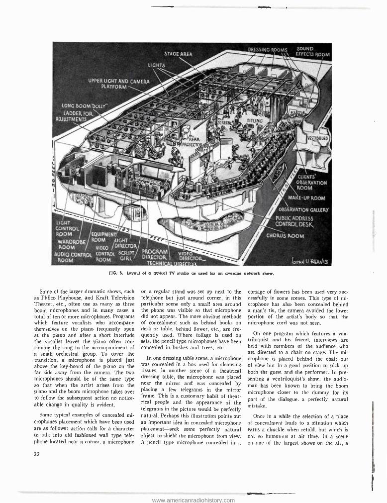
FIG. 5. Layout of a typical TV studio as used for an average network show.
Some of the larger dramatic shows, such as Philco Playhouse, and Kraft Television Theater, etc., often use as many as three boom microphones and in many cases a total of ten or more microphones. Programs which feature vocalists who accompany themselves on the piano frequently open at the piano and after a short interlude the vocalist leaves the piano often con- tinuing the song to the accompaniment of a small orchestral group. To cover the transition, a microphone is placed just above the key -board of the piano on the far side away from the camera. The two microphones should be of the same type so that when the artist arises from the piano and the boom microphone takes over to follow the subsequent action no notice- able change in quality is evident.
Some typical examples of concealed mi- crophones placement which have been used are as follows: action calls for a character to talk into old fashioned wall type tele- phone located near a corner, a microphone
22
on a regular stand was set up next to the telephone but just around corner, in this particular scene only a small area around the phone was visible so that microphone did not appear. The more obvious methods of concealment such as behind books on desk or table, behind flower, etc., are fre- quently used. Where foliage is used on sets, the pencil type microphones have been concealed in bushes and trees, etc.
In one dressing table scene, a microphone was concealed in a box used for cleansing tissues, in another scene of a theatrical dressing table, the microphone was placed near the mirror and was concealed by placing a few telegrams in the mirror frame. This is a customary habit of theat- rical people and the appearance of the telegrams in the picture would be perfectly natural. Perhaps this illustration points out an important idea in concealed microphone placement -seek some perfectly natural object to shield the microphone from view. A pencil type microphone concealed in a
l U. RaJls
corsage of flowers has been used very suc- cessfully in some scenes. This type of mi- crophone has also been concealed behind a man's tie, the camera avoided the lower portion of the artist's body so that the microphone cord was not seen.
On one program which features a ven- triloquist and his friend, interviews are held with members of the audience who are directed to a chair on stage. The mi- crophone is placed behind the chair out of view but in a good position to pick up both the guest and the performer. In pre- senting a ventriloquist's show, the audio - man has been known to bring the boom microphone closer to the dummy for its part of the dialogue. a perfectly natural mistake.
Once in a while the selection of a place of concealment leads to a situation which earns a chuckle when retold, but which is not so humorous at air time. In a scene on one of the largest shows on the air, a
www.americanradiohistory.com
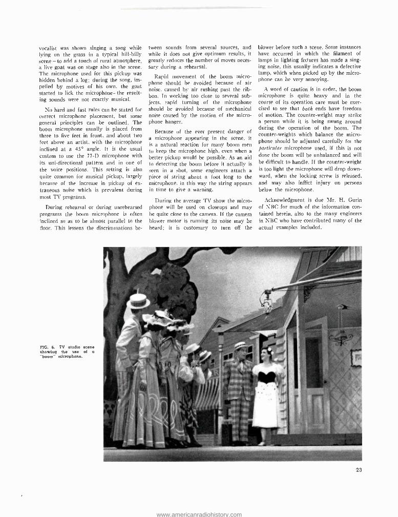
vocalist was shown singing a song while lying on the grass in a typical hill -billy scene -to add a touch of rural atmosphere, a live goat was on stage also in the scene. The microphone used for this pickup was hidden behind a log: during the song, im- pelled by motives of his own, the goat started to lick the microphone -the result- ing sounds were not exactly musical.
No hard and fast rules can be stated for correct microphone placement, but some general principles can be outlined. The boom microphone usually is placed from three to five feet in front, and about two feet above an artist, with the microphone inclined at a 45° angle. It is the usual custom to use the 77 -D microphone with its uni- directional pattern and in one of
the voice positions. This setting is also quite common for musical pickup, largely because of the increase in pickup of ex- traneous noise which is prevalent during most TV programs.
During rehearsal or during unrehearsed programs the boom microphone is often inclined so as to be almost parallel to the floor. This lessens the discriminations be-
FIG. 6. TV studio scene showing the use of a "boom" microphone.
tween sounds from several sources, and while it does not give optimum results, it greatly reduces the number of moves neces- sary during a rehearsal.
Rapid movement of the boom micro- phone should be avoided because of air noise, caused by air rushing past the rib- bon. In working too close to several sub- jects, rapid turning of the microphone should be avoided because of mechanical noise caused by the motion of the micro- phone hanger.
Because of the ever present danger of a microphone appearing in the scene, it is a natural reaction for many boom men to keep the microphone high, even when a better pickup would be possible. As an aid to detecting the boom before it actually is seen in a shot, some engineers attach a piece of string about a foot long to the microphone. in this way the string appears in time to give a warning.
During the average TV show the micro- phone will be used on closeups and may be quite close to the camera. If the camera blower motor is running its noise may be heard; it is customary to turn off the
blower before such a scene. Some instances have occurred in which the filament of lamps in lighting fixtures has made a sing- ing noise, this usually indicates a defective lamp, which when picked up by the micro- phone can be very annoying.
A word of caution is in order, the boom microphone is quite heavy and in the course of its operation care must be exer- cised to see that both ends have freedom of motion. The counter- weight may strike a person while it is being swung around during the operation of the boom. The counter- weights which balance the micro- phone should be adjusted carefully fox the particular microphone used, if this is not done the boom will be unbalanced and will be difficult to handle. If the counter- weight is too light the microphone will drop down- ward, when the locking screw is released. and may also inflict injury on persons below the microphone.
Acknowledgment is due Mr. H. Gurin of NBC for much of the information con- tained herein, also to the many engineers in NBC who have contributed many of the actual examples included.
23
www.americanradiohistory.com
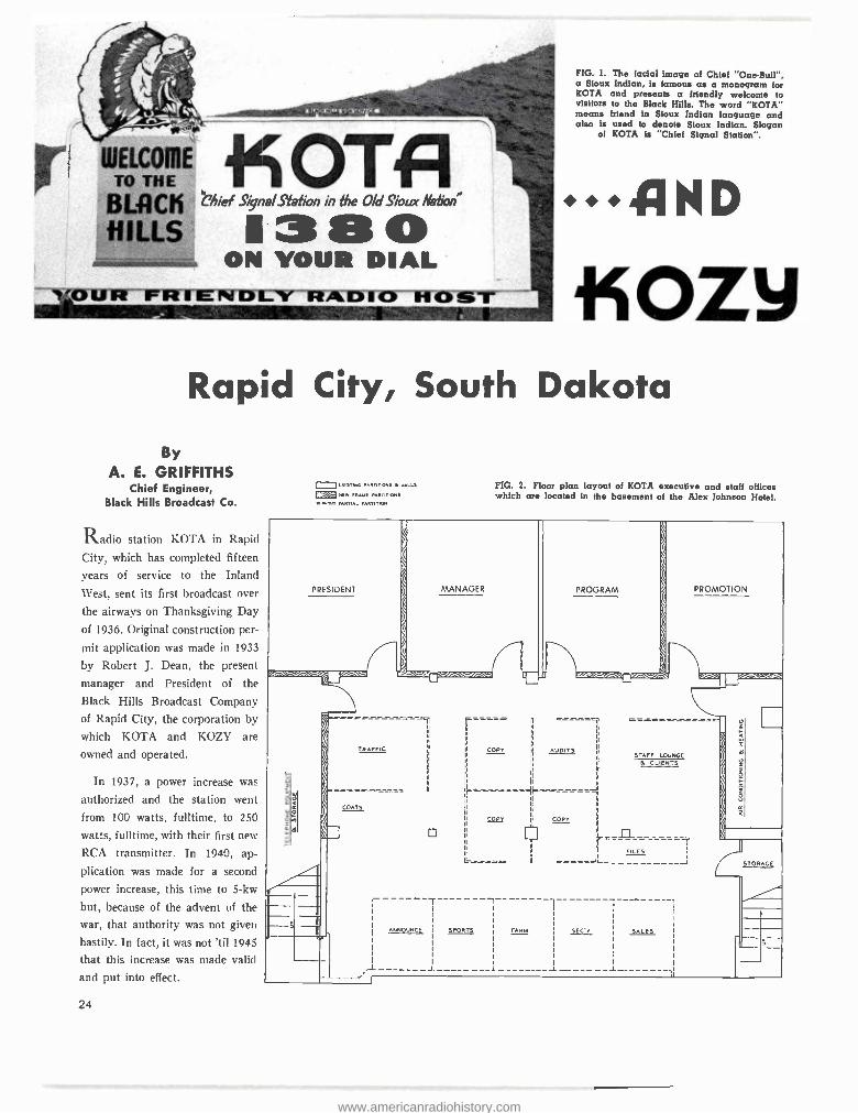
WELCOME TO THE
BLflCñ HILLS
. _ ..c . >t . r,
OT1 Chief Signal Station in the Old Sioux Nation X380
ON YOUR DIAL
FIG. 1. The facial image of Chief "One.Bull ", a Sioux Indian, is famous as a monogram for KOTA and presents a friendly welcome to visitors to the Black Hills. The word "KOTA" means friend in Sioux Indian language and also is used to denote Sioux Indian. Slogan
of KOTA is "Chief Signal Station".
AND iíOZy
Rapid City, South Dakota
By A. E. GRIFFITHS
Chief Engineer, Black Hills Broadcast Co.
Radio station KOTA in Rapid
City, which has completed fifteen
years of service to the Inland
\Vest, sent its first broadcast over
the airways on Thanksgiving Day
of 1936. Original construction per-
mit application was made in 1933
by Robert J. Dean, the present
manager and President of the
Black Hills Broadcast Company of Rapid City, the corporation by which KOTA and KOZY are
owned and operated.
In 1937, a power increase was
authorized and the station went
from 100 watts, fulltime, to 250
watts, fulltime, with their first new
RCA transmitter. In 1940, ap-
plication was made for a second
power increase, this time to 3 -kw
but, because of the advent of the
war, that authority was not given
hastily. In fact, it was not 'til 1945
that this increase was made valid
and put into effect.
24
o EXISTING PARTITIONS ...L_, ® NEW FRAME PARTITIONS
PARTIAL PARTITION
FIG. 2. Floor plan layout of KOTA executive and staff offices which are located in the basement of the Alex Johnson Hotel.
PROGRAM PROMOTION
1
COPY AUDITS STAFF LOUNGE
& CLIENTS
r
COPY COPY
LLLv>sa
L__1L___ r--
FILES I - c-=ccJl_-
1
SPORTS FARM SEC'V SALES
1_ 1
www.americanradiohistory.com
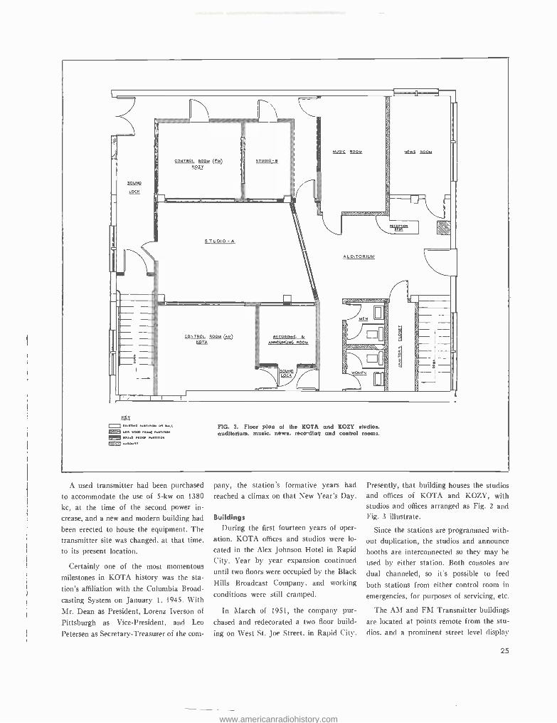
CONTROL ROOM (fM) ROZY
STUDIO Ie
r
RECORDING & ANNOUNCING ROOM
KEY = euellNG tiRTITroM OR WALL ® .aw room Flwe PS.TITION 0 SOUND PROOF PARTITION
! 1 N.RO.RT
FIG. 3. Floor plan of the KOTA and KOZY studios. auditorium, music, news, reco-ding and control rooms.
A used transmitter had been purchased
to accommodate the use of 5 -kw on 1380
kc, at the time of the second power in-
crease, and a new and modern building had
been erected to house the equipment. The
transmitter site was changed, at that time.
to its present location.
Certainly one of the most momentous
milestones in KOTA history was the sta-
tion's affiliation with the Columbia Broad-
casting System on January 1, 1945. With
Mr. Dean as President, Lorenz Iverson of
Pittsburgh as Vice -President, and Leo
Petersen as Secretary- Treasurer of the corn-
pany, the station's formative years had reached a climax on that New Year's Day.
Buildings During the first fourteen years of oper-
ation, KOTA offices and studios were lo-
cated in the Alex Johnson Hotel in Rapid
City. Year by year expansion continued
until two floors were occupied by the Black
Hills Broadcast Company, and working
conditions were still cramped.
In March of 1951, the company pur-
chased and redecorated a two floor build-
ing on West St. Joe Street. in Rapid City.
Presently, that building houses the studios and offices of KOTA and KOZY, with studios and offices arranged as Fig. 2 and Fig. 3 illustrate.
Since the stations are programmed with- out duplication, the studios and announce booths are interconnected so they may be
used by either station. Both consoles are
dual channeled, so it's possible to feed
both stations from either control room in
emergencies, for purposes of servicing, etc.
The AM and FM Transmitter buildings
are located at points remote from the stu-
dios. and a prominent street level display
25
www.americanradiohistory.com
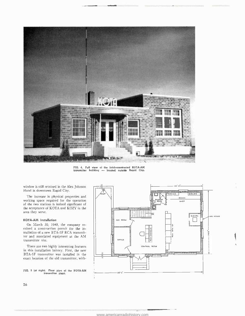
-..rw-- i JrJ' R.Ñ a.v-Narra.. aN= ,. _.m.. .
o...: - WWII MOO °°- a_: tr...tttwr,r+. 'wj ; II lii ;--17 " .. ._ _
? a . Wá.m -_--._-__ --lYM.- AMU ., _ - ,... ..- in Ii/ w..... -..
le.i:-.. .,z... _....
111111111111a....
MI- : S40atrreartrsïYN1*a ::= r.11111F . . rlOW .. :oNtr-t r- OM, rwr, rs- -r.. . .. w- ...rr ems.
FIG. 4. Full view of the brick -constructed KOTA -AM transmitter building - located outside Rapid City.
window is still retained in the Alex Johnson Hotel in downtown Rapid City.
The increase in physical properties and working space required for the operation of the two stations is indeed significant of the acceptance of KOTA and KOZY in the area they serve.
KOTA -AM Installation On March 30, 1948, the company re-
ceived a construction permit for the in- stallation of a new BTA -5F RCA transmit- ter and associated equipment at the AM transmitter site.
There are two highly interesting features in this installation hsitory. First, the new BTA -5F transmitter was installed in the exact location of the old transmitter, with-
FIG. 5 (at right). Floor plcn of the KOTA -AM transmitter plant.
26
UMP
N
D ROOM
C OFFICE
CONTROL ROOM
Si 0
fI
BLOWER
n
as
Ili
AIR INTAKE
www.americanradiohistory.com
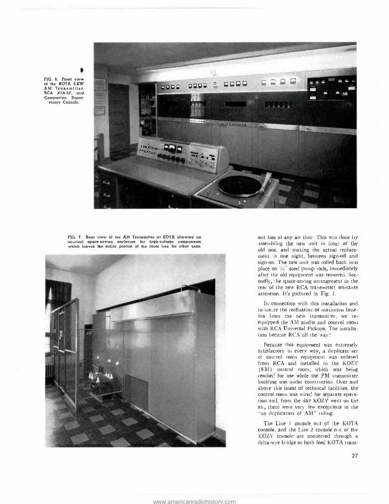
FIG. 6. Front view of the KOTA 5 -KW AM Transmitter. RCA BTA -5F, and Companion Super-
visory Console.
FIG. 7. Rear view of the AM Transmitter at KOTA showing an unusual space- saving enclosure for high -voltage components which leaves the major portion of the room free for other uses.
out loss of any air time. This was done by assembling the new unit in front of the old one, and making the actual replace- ment in one night, between sign -off and sign -on. The new unit was rolled back into place on Y8" steel pump rods, immediately after the old equipment was removed. Sec- ondly, the space -saving arrangement in the rear of the new RCA transmitter warrants attention. It's pictured in Fig. 7.
In connection with this installation and to insure the realization of maximum bene- fits from the new transmitter, we re- equipped the AM studio and control room with RCA Universal Pickups. The installa- tion became RCA all the way!
Because this equipment was extremely satisfactory in every way, a duplicate set of control room equipment was ordered from RCA and installed in the KOZY (FM) control room, which was being readied for use while the FM transmitter building was under construction. Over and above this finest of technical facilities, the control room was wired for separate opera- tion and, from the day KOZY went on the air, there were very few exceptions to the "no duplication of AM" ruling.
The Line 1 console out of the KOTA console, and the Line 2 console out of the KOZY console are connected through a
delta -wye bridge so both feed KOTA trans-
27
www.americanradiohistory.com
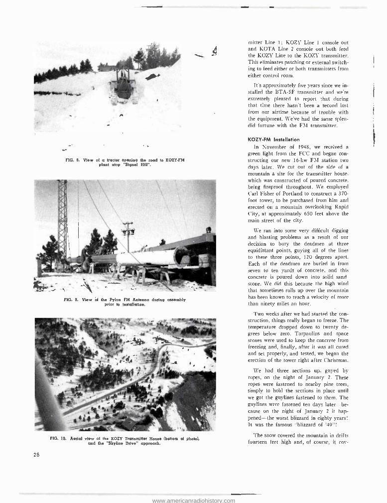
FIG. 8. View of a tractor opening the road to KOZY -FM plant atop "Signal Hill ".
4
FIG. 9. View of the Pylon FM Antenna during assembly prior to installation.
FIG. 10. Aerial view of the KOZY Transmitter House (bottom of photo), and the "Skyline Drive" approach.
28
mitter Line 1; KOZY Line 1 console out and KOTA Line 2 console out both feed the KOZY Line to the KOZY transmitter. This eliminates patching or external switch- ing to feed either or both transmitters from either control room.
Its approximately five years since we in- stalled the BTA -5F transmitter and we're extremely pleased to report that during that time there hasn't been a second lost from our airtime because of trouble with the equipment. We've had the same splen- did fortune with the FM transmitter.
KOZY -FM Installation In November of 1948, we received a
green light from the FCC and began con- structing our new 16 -kw FM station two days later. We cut out of the side of a
mountain a site for the transmitter house. which was constructed of poured concrete. being fireproof throughout. We employed Carl Fisher of Portland to construct a 370 - foot tower, to be purchased from him and erected on a mountain overlooking Rapid City, at approximately 650 feet above the main street of the city.
We ran into some very difficult digging and blasting problems as a result of our decision to bury the deadmen at three equidistant points, guying all of the lines to these three points, 120 degrees apart. Each of the deadmen are buried in from seven to ten yards of concrete, and this concrete is poured down into solid sand- stone. We did this because the high wind that sometimes rolls up over the mountain has been known to reach a velocity of more than ninety miles an hour.
Two weeks after we had started the con- struction, things really began to freeze. The temperature dropped down to twenty de- grees below zero. Tarpaulins and space stoves were used to keep the concrete from freezing and, finally, after it was all cured and set properly, and tested, we began the erection of the tower right after Christmas.
We had three sections up, guyed by ropes, on the night of January 2. These ropes were fastened to nearby pine trees, simply to hold the sections in place until we got the guylines fastened to them. The guylines were fastened ten days later -be- cause on the night of January 2 it hap- pened- -the worst blizzard in eighty years! It was the famous "blizzard of '49 "!
The snow covered the mountain in drifts fourteen feet high and, of course, it coy-
www.americanradiohistory.com
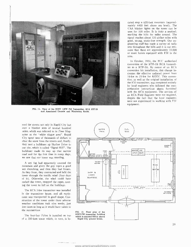
FIG. 11. View of the KOZY 3 -KW FM Transmitter, RCA BTF -3B and Associated Console and Monitoring Racks.
cred the streets not only in Rapid City but over a blanket area of several hundred miles, which was referred to in Time Mag- azine as the "white plague area ". Rapid City spent tens of thousands of dollars to clear the snow from the streets and, finally, they sent a bulldozer up Skyline Drive to our site, which is called "Signal Hill ". The bulldozer made its way up that narrow road and for the first time in many days, we saw that our tower was standing.
A wet fog had apparently covered the mountain and given the guy ropes a good wet drenching, and then they had frozen. As they froze, they contracted and held the tower through the terrific wind (four days of it). Otherwise, the wind could have rocked the tower, snapped the ropes, caus- ing the tower to fall on the buildings.
The RCA 3 -kw transmitter was installed in the transmitter house, and all equip- ment was transported in good shape. Con- struction of the tower under these adverse weather conditions took nine weeks, just five times as long as it would have taken in
the summertime.
The four -bay Pylon is installed on top of a 300 -foot tower which, in turn, is lo-
cated atop a 650 -foot mountain (approxi- mately 4400 feet above sea level). The CAA blinker lights on the tower can be seen for 100 miles. It is truly a sentinel, marking the hills for miles around. The signal reaches about 120 airline miles with good, strong, static -free strength. Our en- gineering staff has made a survey of radio sets throughout the hills and it is our esti- mate that there are approximately 22,000 or more homes equipped with FM in the area.
In October, 1951, the FCC authorized conversion of the BTF -3B RCA transmit- ter to a BTF -5A. By means of an RCA conversion kit installation, this change in- creases the effective radiated power from 16 -kw to 25 -kw for KOZY. This conver- sion, as well as the original installation of the FM transmitter, was completed entirely by local engineers who followed the com- prehensive instructions sheets furnished with the RCA equipment. The services of an RCA Field Engineer were not required. despite the fact that the local engineers were not experienced in working with FM equipment.
FUEL TANK iii. cy iiiii,
%
o, SHOWER Ì EXHAUST
POWER PANEL
/ 1U MP
STOOL
__ ----- MONITOR
INPUT
AND
EOVIP. r___ ___
HEAT II
/y% WATER-
NEATER
SHOP & LIVING
QUARTERS
/ /
I
I I
WCIA I
I
SB TSB
I I
i I
I I i
I ,
/
a V
I I TELE I I TERM
1 _____ _ J L _FLOOR DVCTS_____ --
FILTERED AIR INTAKE
41111111
' '
/ME
FIG. 12. Floor plan of the KOZY -FM transmitter building which is situated 650 ft. above
Rapid City ground levels.
2 9
www.americanradiohistory.com
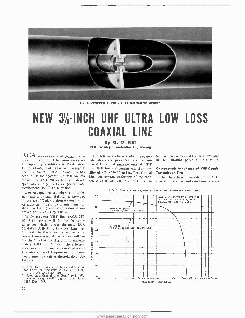
FIG. 1. Photograph of UHF 31/2" 50 ohm undercut insulator.
NEW 31/8-INCH UHF ULTRA LOW LOSS
COAXIAL LINE
RCAhas demonstrated coaxial trans- mission lines for UHF television under ac- tual operating conditions in Washington, D. C. (1948) and again in Bridgeport, Conn., where 250 feet of 3% -inch line has been in use for 2 years.' .7 Now a low loss coaxial line (MI- 19089) has been devel- oped which fully meets all performance requirements for UHF television.
Low loss qualities are inherent in its de- sign and additional stability is provided by the use of Teflon dielectric components. Attenuation is held to a minimum (as shown in Fig. 3) and power rating is im- proved as indicated by Fig. 4.
While previous VHF line (RCA MI- 19113 -1) serves well in the frequency range for which it was designed, RCA MI -19089 UHF Ultra Low Loss Line may be used effectively for radio frequency power transmission at frequencies well be- low the broadcast band and up to approxi- mately 1000 mc. A "flat" characteristic impedance of 50 ohms is maintained across this wide range of frequencies -by actual measurement as well as theoretically. (See Fig. 2.)
1 "Ultra -High Frequency Antenna and System for Television Transmission" by O. O. Fiet, RCA REVIEW, June 1950.
7 "Notes on a Coaxial Line Bead" by D. W. Peterson, Proc. I.R.E., Vol. 37, No. 11, p. 1294, Nov. 1949.
30
By O. O. FIET RCA Broadcast Transmitter Engineering
The following characteristic impedance calculations and graphical data are con- firmed by actual measurements of VHF and UHF lines and demonstrate the versa- tility of MI -19089 Ultra Low Loss Coaxial Line. An accurate evaluation of the char- acteristics of both VHF and UHF line can
52
51
50
Ì 47
44
45
be made on the basis of the data presented in the following pages of this article.
Characteristic Impedance of VHF Coaxial Transmission Line
"I'he characteristic impedance of VHF coaxial lines whose uniform -diameter inner
FIG. 2. Characteristic impedance of RCA 31/2" diameter coaxial lines.
NOMINAL CHARACTERISTIC IMPEDANCE VS. FREQUENCY OF RCA 3i INCH COAXIAL TRANSMISSION LINES
---i MI- 19113 -I,
51.5 OHM 31, VHF COAXIAL LINE
MI -19089 -1 J 50.0 OHM 31-91411 UHF COAXIAL LINE
FREQUENCY - MEGACYCLES
www.americanradiohistory.com
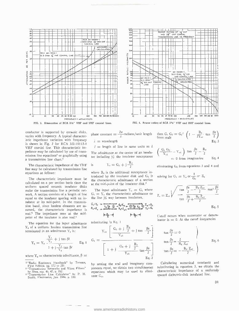
I.0 .90 no .70
30 RCA MI- 19089 -I S0.0 OHM 3p-INCH UHF
COAXIAL LINE .40
MEASURED
30 RCA MI- 19131 51.5 OHM 3 VHF COAXIAL
.20
10 .09
8 7 .00
DL
Or
a
.03
0E
10 30 30 40 50 60 70 80 IOO 200 300 440 500 600 700 0101000
FREQUENCY - MEGACYCLES
FIG. 3. Attenuation of RCA 3'/e" VHF and UHF coaxial lines.
conductor is supported by ceramic disks, varies with frequency. A typical character- istic impedance variation with frequency is shown in Fig. 2 for RCA MI- 19113 -1
VHF coaxial line. This characteristic im- pedance may be calculated by use of trans- mission line equation- or graphically using a transmission line chart.3
The characteristic impedance of the VHF line may be calculated by transmission line equations as follows:
The characteristic impedance must be calculated on a per section basis since the uniform spaced ceramic insulator disks make the transmission line a periodic net- work. A section consists of a length of line equal to the insulator spacing with an in- sulator at its mid -point. In the transmis- sion band, since lossless elements are as- sumed, the characteristic impedance is real3 The impedance seen at the mid- point of the insulator is also real.'
The equation for the input admittance Y3 of a uniform lossless transmission line terminated in an admittance Yr is:
Yr j tan ßl
Y, = Yo _
1 + j 1-Y,- tan f31
where Yo = characteristic admittance, (3 =
Eq. 1
2 "Radio Engineers Handbook" by Terman, First Edition, pp. 172 to 251.
3 "Transmission Networks and Wave Filters" by Shea, eqs. 46, 47, p. 192. "Transmission Lille Calculator" by P. H. Smith, Electronics, Jan. 1944, p. 130.
900- ... 700____ 00
500
4.0
See , . _-ws 7o- LO
50 40 iO..,.,uii1"',"i 20
1
---ll _--..,,_- IlNttMI11111t1 11111M11111111111111111MMIIIIIIIMM POWER RATING OF 36 VHF
AND 311.
UHF COAX AL TRANSMISSION LINE VS. FREQUENCY
MMilipl... IMElllltlIIIlEME -muli.,
III - MU
Inn 111 1111
111111 ill11ii Mill
1111 Ellin - l uff
1EMIt\ME MI -19113-1 51.5 OHM
O.D. VHF
rm_" p -.ul1,u-mul1111 COAXIAL
11II 1111
III 112.11111111L.
MI-19069 -I NNMN IllIi1111 50.0 OHM. 30.0
UHF COAXIAL LINE
MEASURED (1,MMMill 11011.1.1..... _-11.11111111.
1111
_ LINE LINE IliMMI NEI
ion 1111 1 ls Iil 11I ii liuuu .11
bIli II III uiui111Ill
10 m 30 10 SO LO 70 80 100 !00 300 400 530 6.70 R1 1000
FREQUENCY - MEGACYCLES
FIG. 4. Power rating of RCA 31/4" VHF and UHF coaxial line..
phase constant = ir radians /unit length
Â
i. = wavelength
l = length of line in same units as 2
The admittance at the center of an insula- tor including '/2 the insulator susceptance
Bd is Yr =G_+j
2
where Bd is the additional susceptance in- troduced by the insulator disk and G2 is
the characteristic admittance of a section at the mid -point of the insulator disk .3
The input admittance Y., = G1 where G1 = Y the characteristic admittance on
the line % way between insulators,
GS=Yo ' a J__
P 3
Ze=Rl R1=Zo y Y°1-m Rÿ Z i ci
oe I
4- = -( I substituting in Eq. 1
G1 =
1701 I
G_ + J
d
tan {3s 2
Yo1
Gs + Bd
tan ß2 Eq. 2
Yo1
by setting the real and imaginary com-
ponents equal, we obtain two simultaneous equations which may be used to elimi- nate G2,
B,I then G1 G2 = G12 (1 _ 2Y0 from reals ßs )tan
Eq. 3
( G' GI! - Y1 !
tan ?? - Bd
`` Y,,1 ! 1 2
= 0 from imaginaries Eq. 4
tan
eliminating G_ from equations 3 and 4 and
solving for G1 = Y or 1 = 4
Z = t Ps
s - Bd Z00 tan=
ßs
(3s Bd Zoi tan 2+ 2
Eq. 5
Cutoff occurs when numerator or denom-
inator is = O. At the cutoff frequencies
tan s
2 = 0
ßs 2 tan
2 Bd Zo1
Os Bd Zo1 tant=
Eq. 6
Calculating numerical constants and
substituting in equation 5, we obtain the
characteristic impedance of a uniformly spaced dielectric -disk insulated line.
31
www.americanradiohistory.com
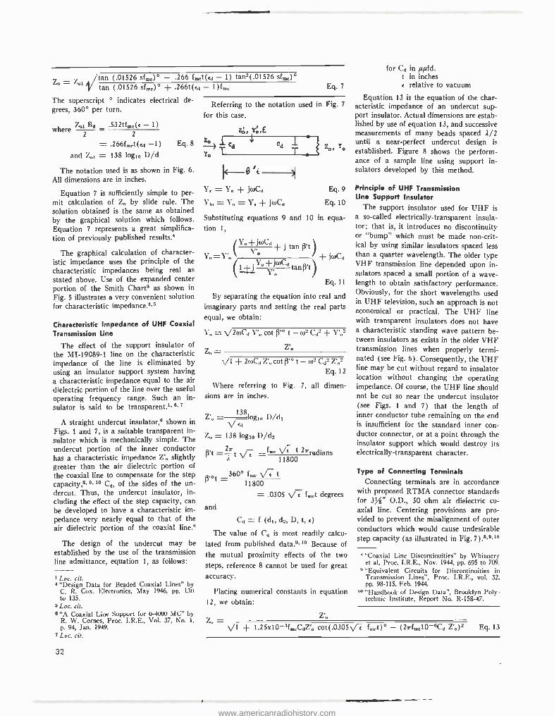
tan (.01526 stifle)* - .266 finet(cd - 1) tan2(.01526 sfine)°
tan (.01526 sfine)° + .166t(cd - 1)fmi.
The superscript ° indicates electrical de- grees, 360° per turn.
where 41 Bd .532tfine(e - 1)
2 2
_ .266finet(ed -1) Eq. 8
and Z,,1 = 138 logio D/d
The notation used is as shown in Fig. 6.
All dimensions are in inches.
Equation 7 is sufficiently simple to per- mit calculation of Z° by slide rule. The solution obtained is the same as obtained by the graphical solution which follows. Equation 7 represents a great simplifica- tion of previously published results.4
The graphical calculation of character- istic impedance uses the principle of the characteristic impedances being real as stated above. Use of the expanded center portion of the Smith Charts as shown in Fig. 5 illustrates a very convenient solution for characteristic impedance'
Characteristic Impedance of UHF Coaxial Transmission Line
The effect of the support insulator of
the MI- 19089 -1 line on the characteristic impedance of the line is eliminated by using an insulator support system having a characteristic impedance equal to the air dielectric portion of the line over the useful operating frequency range. Such an in- sulator is said to be transparent'. 8.7
A straight undercut insulator,° shown in
Figs. 1 and 7, is a suitable transparent in- sulator which is mechanically simple. The undercut portion of the inner conductor has a characteristic impedance Z'o slightly greater than the air dielectric portion of the coaxial line to compensate for the step capacity,e.0.10 Cd, of the sides of the un- dercut. Thus, the undercut insulator, in- cluding the effect of the step capacity, can be developed to have a characteristic im- pedance very nearly equal to that of the air dielectric portion of the coaxial line .°
The design of the undercut may be established by the use of the transmission line admittance, equation 1, as follows:
1 Loc. cit. 4 "Design Data for Beaded Coaxial Lines" by
C. R. Cox, Electronics, May 1946, pp. 130 to 135.
+Loc. cit.
Eq. 7
Referring to the notation used in Fig. 7
for this case.
Z. TCd
Yo 1
zo, Y°,E
I dd T Zo, TO
Yr = Y. + juke Eq. 9
Yin =Y =Y. +joke Eq.10
Substituting equations 9 and 10 in equa- tion 1,
/ Y° -i- jwC, ß't j tan )
Yo=Y'o Y° l
+ JwCd
(1 +J Yo+JwCd tanß,t/ \\ Y'
Eq. 11
By separating the equation into real and imaginary parts and setting the real parts equal, we obtain:
1- = V2wC,, Y'o cot ß'° t - w C,12 + Y'o2
Z'° Z. = ,\/1 + 2wC,1 Z' cot ß'O t - w2 Cd2 Z'02
Eq. 12
Where referring to Fig. 7, all dimen- sions are in inches.
___ 138
log,n D/dl Cd
Z = 138 logl0 D/d2
ß't =-2-ir =fm. /c t 27rradians 11800
_360° fm° \/7 t 11800
= .0305 N/7 f,,,,t degrees
and
Cd = f (d1, d2, D, t, c)
The value of C,, is most readily calcu- lated from published data 9.10 Because of
the mutual proximity effects of the two
steps, reference 8 cannot be used for great accuracy.
Placing numerical constants in equation 12, we obtain:
6 "A Coaxial Line Support for 0 -4000 MC" by R. W. Cornes, Proc. I.R.E., Vol. 37, No. 1,
p. 94, Jan. 1949. 'I.0 =
7 Loc. cit.
32
for C° in µofd. t in inches e relative to vacuum
Equation 13 is the equation of the char- acteristic impedance of an undercut sup- port insulator. Actual dimensions are estab- lished by use of equation 13, and successive measurements of many beads spaced 2/2 until a near -perfect undercut design is
established. Figure 8 shows the perform- ance of a sample line using support in- sulators developed by this method.
Principle of UHF Transmission Line Support Insulator
The support insulator used for UHF is a so- called electrically- transparent insula- tor; that is, it introduces no discontinuity or "bump" which must be made non -crit- ical by using similar insulators spaced less than a quarter wavelength. The older type VHF transmission line depended upon in- sulators spaced a small portion of a wave- length to obtain satisfactory performance. Obviously, for the short wavelengths used in UHF television, such an approach is not economical or practical. The UHF line with transparent insulators does not have a characteristic standing wave pattern be- tween insulators as exists in the older VHF transmission lines when properly termi- nated (see Fig. 6). Consequently, the UHF line may be cut without regard to insulator location without changing the operating impedance. Of course, the UHF line should not be cut so near the undercut insulator (see Figs. 1 and 7) that the length of inner conductor tube remaining on the end is insufficient for the standard inner con- ductor connector, or at a point through the insulator support which would destroy its electrically- transparent character.
Type of Connecting Terminals Connecting terminals are in accordance
with proposed RTMA connector standards for 35" O.D., 50 ohm air dielectric co- axial line. Centering provisions are pro- vided to prevent the misalignment of outer conductors which would cause undesirable step capacity (as illustrated in Fig. 7).8.9.'°
"Coaxial Line Discontinuities" by Whinnery et al, Proc. I.R.E., Nov. 1944, pp. 695 to 709.
° "Equivalent Circuits for Discontinuities in Transmission Lines ", Proc. I.R.E., vol. 32, pp. 98 -115, Feb. 1944.
10 "Handbook of Design Data ", Brooklyn Poly- technic Institute, Report No. R- 158 -47.
+ I.25x10-5fmeCdZ'o cot(.0305f f,°et)° - (2rfinel0-6Cd Z'o)2 Eq. 13
www.americanradiohistory.com
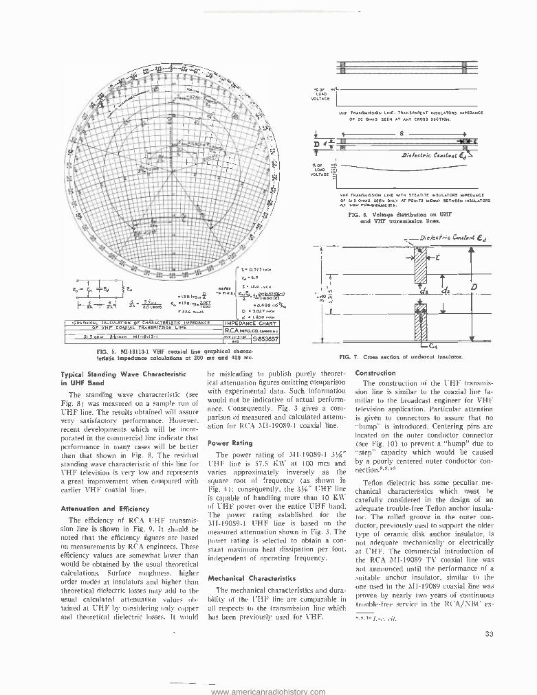
,r,.. f;iiElE31is iilltht: 40
/'ø*. ccc:i
!! -
° 1 1
t;i. 44,111141114141110.04..0102.k Tlr1lgwrsi . 0° pt.lr; iitir.WftcllaI1 ¡¡ii¡ii¡iiiiiiiiiñiii¡i¡¡iii . iiiiiiai.Iiiiiiiií .f : 1 ..\:::\FoI:m\Ì1j
y!i¡;,¡:'..:'::::::ñ::ïA¡¡: j',rP pe ¡ii¡¡l'wiGiiiiiöiiiii iee4¡e: 1eeO ¡er.r.Qeei =eee=ee¡.
1¡i 1 ¡¡¡¡¡¡iiiii iiri iiiiii ei ¡íe¡ A016:81111111:1 iiiiiiiiii4nMF ;= iiiiiiiiiiúiiiiiiiiie' A
$ kl TBa
I wTz 1
. REF!R T
s lift-'-0.3.33-
2O1 13B Iqw3.osT 2A I LoG
.13IS 103,.
v 53.4 own!
t 0.3731N0H
Eo 4.0
5 12.0 INCH
>Tn1 j,rt(0.T75r¡-Il
Z -t« eo0(z}
0.4991Ó3}, D 3.027 ew F( 1.200 ,NcH
GRAPHICAL CALCULATION OF CHARACTERISTIC IMPEDANCE OF VHF COA}IIAL TRANSMISSION LINE
IMPEDANCE CHART RCA MFa.00. TAINNRA
51.5oNM 9{ INCH MI-19113-I ° IEN,
31 Isß53557
FIG. 5. MI- 19113.1 VHF coaxial line graphical charac- teristic impedance calculations at 200 mc and 400 mc.
Typical Standing Wave Characteristic in UHF Band
The standing wave characteristic (see
Fig. 8) was measured on a sample run of UHF line. The results obtained will assure very satisfactory performance. However. recent developments which will be incor- porated in the commercial line indicate that performance in many cases will be better than that shown in Fig. 8. The residual standing wave characteristic of this line for VHF television is very low and represents a great improvement when compared with earlier VHF coaxial lines.
Attenuation and Efficiency
The efficiency of RCA UHF transmis- sion line is shown in Fig. 9. It should be noted that the efficiency figures are based on measurements by RCA engineers. These efficiency values are somewhat lower than would be obtained by the usual theoretical calculations. Surface roughness, higher order modes at insulators and higher than theoretical dielectric losses may add to the usual calculated attenuation values ob- tained at UHF by considering only copper and theoretical dielectric losses. It would
%OF LOAD
VOLTAGE
UHF TRANSMISSION LINE. TRANSPARENT INSULATORS
OF SO 0H03 SEEN AT ANY CROSS SECTION.
t5-7,7 fi - x Or LOAD
VOLTAGE I.:
fá
IMPEDANCE
-Want
D;e/tetP;C CON Ste Ht Ed
VHF TRANSMISSION LINE WITH STEATITE INSULATORS IMPEDANCE OF Si 3 OHMS SEEN ONLY AT POINTS MIDWAY BETWEEN INSULATORS AT LOW FRUau4WCIaS.
FIG. 6. Voltage distribution on UHF and VHF transmission lines.
,_.-.D;QkCtP;C CR,Er>Mt Ed 1
C4
FIG. 7. Cross section of undercut Insulator.
be misleading to publish purely theoret- ical attenuation figures omitting comparison with experimental data. Such information would not be indicative of actual perform- ance. Consequently, Fig. 3 gives a com- parison of measured and calculated attenu- ation for RCA MI- 19089 -1 coaxial line.
Power Rating
The power rating of MI- 19089 -1 31/4"
UHF line is 57.5 KW at 100 mcs and varies approximately inversely as the square root of frequency (as shown in Fig. 4); consequently, the 3yií" UHF line is capable of handling more than 10 KW of UHF power over the entire UHF band. The power rating established for the MI- 19089 -1 UHF line is based on the measured attenuation shown in Fig. 3. The power rating is selected to obtain a con- stant maximum heat dissipation per foot, independent of operating frequency.
Mechanical Characteristics
1'he mechanical characteristics and dura- bility of the UHF line are comparable in all respects to the transmission line which has been previously used for VHF.
Construction
The construction of the UHF transmis- sion line is similar to the coaxial line fa- miliar to the broadcast engineer for VHF television application. Particular attention is given to connectors to assure that no
"bump" is introduced. Centering pins are located on the outer conductor connector (see Fig. 10) to prevent a "bump" due to "step" capacity which would be caused
by a poorly centered outer conductor con- nection!"." to
Teflon dielectric has some peculiar me- chanical characteristics which must be carefully considered in the design of an adequate trouble -free Teflon anchor insula- tor. The rolled groove in the outer con- ductor, previously used to support the older type of ceramic disk anchor insulator, is
not adequate mechanically or electrically at UHF. The commercial introduction of the RCA MI -19089 TV coaxial line was
not announced until the performance of a
suitable anchor insulator, similar to the
one used in the MI -19089 coaxial line was
proven by nearly two years of continuous trouble -free service in the RCA /NBC ex-
. D. LO I.111'.
33
www.americanradiohistory.com
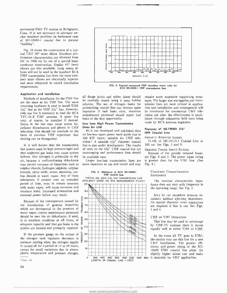
perimental UHF TV station at Bridgeport, Conn. It is not necessary to alternate an- chor insulator positions on horizontal runs of MI- 19089 -1 coaxial line to prevent "walking ".
Fig. 10 shows the construction of a typ- ical UHF 90° miter elbow. Excellent per- formance characteristics are obtained from DC to 1000 mc by use of a special inner conductor construction. Similar 45° bevel elbows are also available. Long sweep el- bows will not be used in the standard RCA UHF transmission line since the more com- pact miter elbows are electrically superior and more adaptable to varied installation requirements.
Application and Installation Methods of installation for the UHF line
are the same as for VHF line. The same mounting hardware is used to install UHF 3/ " line as for VHF 3/" line. However, only one line is necessary to feed the RCA TFU -24 -B UHF antenna. A spare line may, of course, be installed if desired. Dents in the line may cause severe im- pedance disturbances and ghosts in UHF television. One should not conclude on the basis of previous VHF experience that denting can be disregarded.
It is well known that the transmission line system must be kept pressure -tight and that neglected gas leaks may cause system failures. Dry nitrogen is preferable to dry air, because a malfunctioning dehydrator may permit entrance of impurities such as sulphur dioxide, hydrogen sulphide, sulphur trioxide, nitric oxide, ozone, ammonia, car- bon dioxide or water vapor. Any of these substances, if present over an extended period of time, even in minute amounts with water vapor, will cause corrosion and insulator leaks. Increased attenuation and eventual power failure may result.
Because of the consequences caused by the introduction of gaseous impurities which are detrimental in the presence of water vapor, station maintenance personnel should be sure the air dehydrator, if used, is in excellent condition at all times, of adequate capacity and that gas leaks in the system are located and promptly repaired.
If the pressure gauge on the output of the nitrogen tank regulator decreases in pressure reading when the nitrogen supply is turned off for a period of 12 to 24 hours, except for small variations due to atmos- pheric temperature and pressure changes,
' Loc. cit.
34
FIG. 8. Typical measured UHF standing wave rctio for RCA Mi- 19089 -1 UHF transmission line.
all flange joints and solder joints should be carefully tested using a soap bubble solution. The use of nitrogen tanks for pressurizing coaxial line can become quite expensive if bad leaks exist, therefore maintenance personnel should repair bad leaks at the first opportunity.
Low Loss High Power Transmission Lines for UHF
RCA has developed and published data on low -loss super power wave guide (up to 500 KW input) suitable for UHF tele- vision.' A suitable 6/ " diameter coaxial line is also under development. The results of tests on the 6 / " UHF coaxial line are encouraging and performance data should be available soon.
Larger low -loss transmission lines are more expensive to use and install and may
FIG. 9. Efficiency of RCA MI- 19089.1 UHF coaxial line.
TYPICAL 31/2 INCH O.D. UHF TRANSMISSION LINE EFFICIENCY BASED ON RCA MEASUREMENTS (5- 6 -51)
loo
90
W 80 I-
I-
2 70
60
50
S 40
o
Z 30
E 20
lo
require more expensive supporting struc- tures. The larger size waveguides and trans- mission lines are more critical in applica- tion and installation and consequently will be introduced for commercial UHF tele- vision use after the effectiveness is estab- lished through exhaustive field tests being made by RCA antenna engineers.
Features of MI -19089 31 /e" UHF Coaxial Line
GREATLY REDUCED LOSSES
71.4% of MI- 19113 -1 Coaxial Line at 200 mc. See Figs. 3 and 9.
GREATER POWER INPUT RATING Because of the greatly reduced losses,
see Figs. 9 and 3. The power input rating is greater than for the VHF line. (See Fig. 4.)
o 200 400 800 800 1000 1200 1400 LENGTH OF COAXIAL LINE - FEET
1600
CONSTANT CHARACTERISTIC IMPEDANCE
The nominal characteristic impe- dance does not vary with frequency in the operating range. See Fig. 2.
May be cut anywhere between in- sulators without affecting impedance. No special diameter inner conductors are required if line is cut. See Figs. 1 and 6.
UHF OR VHF OPERATION
This line may be used to advantage by VHF -TV stations since it serves equally well at either VHF or UHF.
In the event all TV goes to UHF, the station may use this line for a new UHF installation. The greater effi- ciency and power rating of the MI- 19089 UHF coaxial line offset the slightly higher initial cost and make it desirable for VHF application.
www.americanradiohistory.com
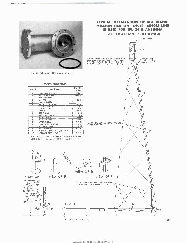
FIG. 10. MI-19089-2 UHF mitered elbow.
SYMBOL DESIGNATIONS
Symbol Description 3tÁ" Die. MI No.
A
B
TRANSMISSION LINE 19089 -1
90° MITER ELBOW 19089 -2
C NOT REQUIRED - D GAS STOP 19089-4 E NOT REQUIRED - F 45° BEVELED ELBOW 19089-3 G COPPER TUBING 19315.1
H ELBOW FITTING 19315-2
J NIPPLE 19315-9
K TEE FITTING 19315-13 M PRESSURE GAUGE 19315.14 N FIXED HANGER See Note 2
P SPRING HANGER See Note 1
R LATERAL BRACE 19313 -36
S HORIZONTAL ANCHOR 19313 -17
T ROLLER ASSEMBLY 19313-35
U SWIVEL HANGER 19313 -37
V NITROGEN TANK- Avallable locally W PRESSURE REGULATOR 19315-19
NOTE I -For 343" line use MI- 19313 -20 through MI-19313-44.
NOTE 2 -For 3W /e" line use MI- 19313 -40 through MI- 19313.44.
VIEW OF T TO TRANSMITTER
M H
VIEW OF R
T OR U _L
TYPICAL INSTALLATION OF UHF TRANS- MISSION LINE ON TOWER- SINGLE LINE
IS USED FOR TFU -24 -B ANTENNA (REFER TO TABLE BELOW FOR SYMBOL DESIGNATIONS)
WHEN SHAPE OF TOWER CHANGES ADD HANGER SUPPORTS TO TOWER THE FOLLOWING ARE MAX, 6° BEND FOR 2 SECTION 3
I LINE
SPACE SPRING HANGERS APPROX. IO FEET APART
VIEW OF S
TO ANTENNA
UPPER TWO HANGERS ARE FIXED TYPE
)
VIEW OF U
ALLOW SEVERAL FEET FROM ELBOW TO HANGER FOR EXPANSION OF LINE
T m
Il
10 FT. APPROX. 35
www.americanradiohistory.com
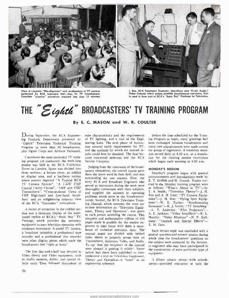
View of complete "Mis- alignment" and re- alignment of TV camera, performed by RCA engineers first -then by TV broadcasters. Complete "practice" procedure required less than 15 minutes.
J. Roe. RCA Television Engineer. describing new TC -4A Audio Video Console which makes possible simultaneous switching. Unit is used to form part of RCA's "Basic Buy" Package for Television.
THE 4 e " BROADCASTERS' TV TRAINING PROGRAM
By E. C. MASON and W. R. COULTER
During September, the RCA Engineer- ing Products Department presented its "Eighth" Television Technical Training Program to more than 80 broadcasters. plus Signal Corps and Airforce Personnel.
Considered the most successful TV train- ing program yet conducted, the week -long session was held in the RCA Exhibition Room in Camden. Space was divided into three sections ; a lecture room, an exhibit or display area, and a luncheon section where posters depicted "A Typical RCA TV Camera System ", "A 1 -KW UHF Coaxial Cavity Circuit ", "VHF and UHF Transmitters ", "Cross- sectional Views of VHF High -band and Low -band Ampli- fiers" and an enlightening cutaway view of the RCA "Starmaker" microphone.
A center of attraction in the exhibit sec- tion was a showcase display of the scale - model replica of RCA's "Basic Buy" TV Package, which provides the necessary equipment to start television operation with minimum investment. A model TV camera. a broadcast turntable, a professional tape recorder and a professional disc recorder were other display pieces which made the broadcasters feel "right at hone ".
The first day -and -a -half was devoted to Video theory and Video equipment, such as studio cameras, dollies, and special ef- fects units. Then followed discussions of
36
tube characteristics and the requirements of TV lighting, and a tour of the Engi- neering Labs. The next phase of instruc- tion covered audio requirements for TV, and the methods by which the desired re- sults could best be obtained. The final lec- tures concerned antennas and the RCA Service Company.
Judging from the comments of the broad- casters themselves, the overall course gave them the latest word in their field, and was outstanding for two reasons. First, the forty RCA and Broadcast Engineers who served as instructors during the week were thoroughly conversant with their subjects. and supplied the answers to operating problems which arose in the broadcasters' minds. Second, the RCA Television Train- ing Manual, which contains the most up- to -date information on "Television Equip- ment, Theory and Operation ", was given to each person attending the course. This complete and authoratative edition of 450 pages made it possible for the station en- gineers to take home with them a store- house of technical television data. The manual pages are divided with tabbed index sheets to properly group data on Transmitters, Antennas, Video, and Audio. To say that the recipients of the manual were pleased is putting it mildly! Never before had there been published so com- prehensive a text on Television Equipment. Theory and Operation -a "must" as an engineering reference.
Before the time scheduled for the Train- ing Program to begin, many greetings had been exchanged between broadcasters and many new acquaintances were made among the group of registrants. A breakfast snack was served daily at 8.30 a.m. as a founda- tion for the training session curriculum which began each morning at 9.00 a.m.
MONDAY'S SESSION \londay's program began with general
announcements and introductions made by E. T. Griffith and H. Duszak. Topics cov- ered in the Monday training program were as follows: "What's Ahead in TV " -by T. A. Smith; "Television Theory " -J. H. Roe and A. H. Lind; "TV Camera Equip - ment"-J. H. Roe; "Flying Spot Equip - ment"--W. E. Tucker; "Synchronizing Generator " -R. J. Smith; "TV Switching" -L. E. Anderson ; "Film Projectors" - A. E. Jackson; "Video Amplifiers " -R. L. Hucaby; "Video Monitors " -N. P. Kell - away; "Genlock and Special Effects" - E. M. Gore.
Each lecture topic was concluded with a general question- and -answer session during which time the broadcasters' questions on the subject were answered by the lecturer, or engineers who may have participated in the construction of some particular type of equipment.
A fifteen minute recess -with refresh- ments- provided relaxation at both the
www.americanradiohistory.com
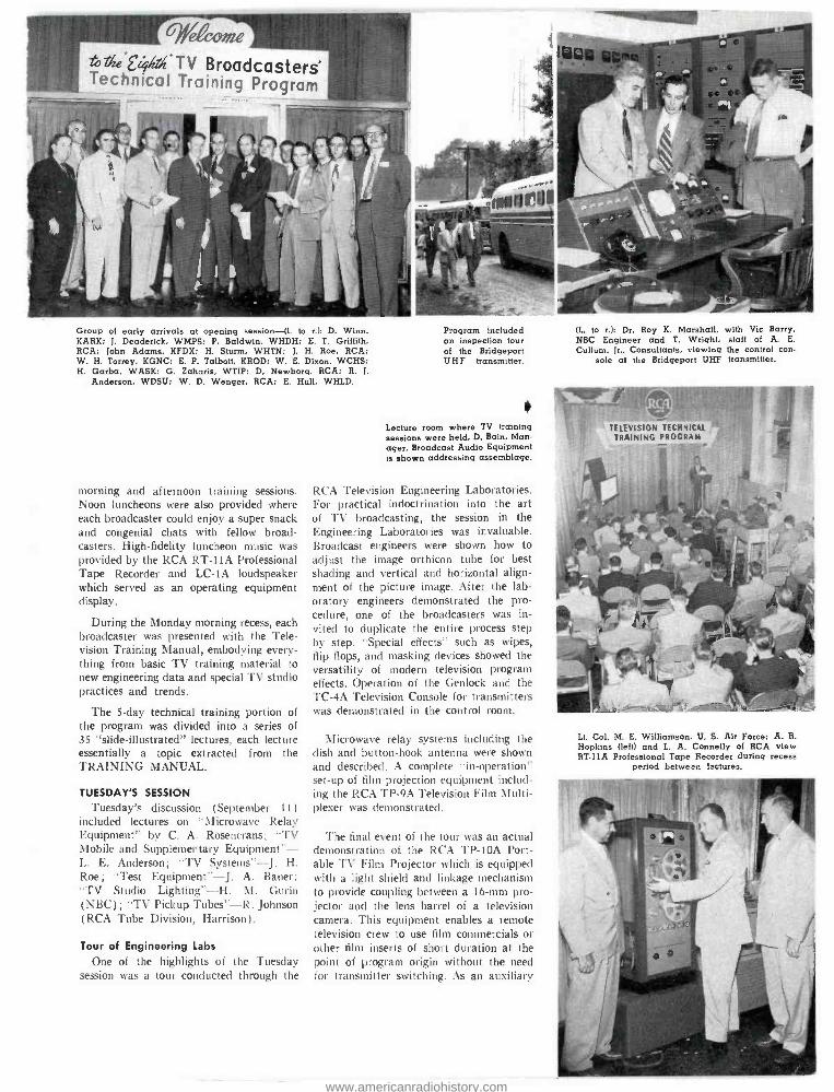
Group of early arrivals at opening session -(1. to r.): D. Winn. KARK; J. Deaderick, WMPS; P. Baldwin, WHDH; E. T. Griffith. RCA; John Adams, KFDX; H. Sturm, WHTN: J. H. Roe, RCA: W. H. Torrey, KGNC; E. P. Talbott, KROD; W. E. Dixon, WCHS; H. Garba, WASK; G. Zaharis, WTIP; D. Newborg, RCA; R. J.
Anderson, WDSU; W. D. Wenger, RCA; E. Hull. WHLD.
morning and afternoon training sessions. Noon luncheons were also provided where each broadcaster could enjoy a super snack and congenial chats with fellow broad- casters. High- fidelity luncheon music was provided by the RCA RT -11A Professional Tape Recorder and LC -IA loudspeaker which served as an operating equipment display.
During the Monday morning recess, each broadcaster was presented with the Tele- vision Training Manual, embodying every- thing from basic TV training material to new engineering data and special TV studio practices and trends.
The 5 -day technical training portion of the program was divided into a series of 35 "slide- illustrated" lectures, each lecture essentially a topic extracted from the TRAINING MANUAL.
TUESDAY'S SESSION
Tuesday's discussion (September 11) included lectures on "Microwave Relay Equipment" by C. A. Rosencrans: "TV Mobile and Supplementary Equipment" - L. E. Anderson; "TV Systems " --J. H. Roe; "Test Equipment " -J. A. Bauer: "TV Studio Lighting " -H. NI. Gurin (NBC); "TV Pickup Tubes " -R. Johnson (RCA Tube Division, Harrison) .
Tour of Engineering Labs
One of the highlights of the Tuesday session was a tour conducted through the
Program included an inspection tour of the Bridgeport UHF transmitter.
Lecture room where TV training sessions were held. D. Bain, Man- ager, Broadcast Audio Equipment is shown addressing assemblage.
RCA Television Engineering Laboratories. For practical indoctrination into the art of TV broadcasting, the session in the Engineering Laboratories was invaluable. Broadcast engineers were shown how to adjust the image orthicon tube for best shading and vertical and horizontal align- ment of the picture image. After the lab- oratory engineers demonstrated the pro- cedure, one of the broadcasters was in- vited to duplicate the entire process step by step. "Special effects" such as wipes, flip flops, and masking devices showed the versatility of modern television program effects. Operation of the Genlock and the TC -4A Television Console for transmitters was demonstrated in the control room.
Microwave relay systems including the dish and button -hook antenna were shown and described. A complete "in- operation" set -up of film projection equipment includ- ing the RCA TP -9A Television Film Multi- plexer was demonstrated.
The final event of the tour was an actual demonstration of the RCA T1' -10A Port- able TV Film Projector which is equipped with a light shield and linkage mechanism to provide coupling between a 16 -mm pro- jector and the lens barrel of a television camera. This equipment enables a remote television crew to use film commercials or other film inserts of short duration at the point of program origin without the need for transmitter switching. As an auxiliary
(L. to r.): Dr. Roy K. Marshall, with Vic Barry. NBC Engineer and T. Wright, staff of A. E. Cullum, Jr., Consultants, viewing the control con-
sole at the Bridgeport UHF transmitter.
` TELEVISION TECHNICAL TRAINING PROGRAM
Lt. Col. M. E. Williamson. U. S. Air Force; A. R. Hopkins (left) and L. A. Connelly of RCA view RT -11A Professional Tape Recorder during recess
period between lectures.
www.americanradiohistory.com
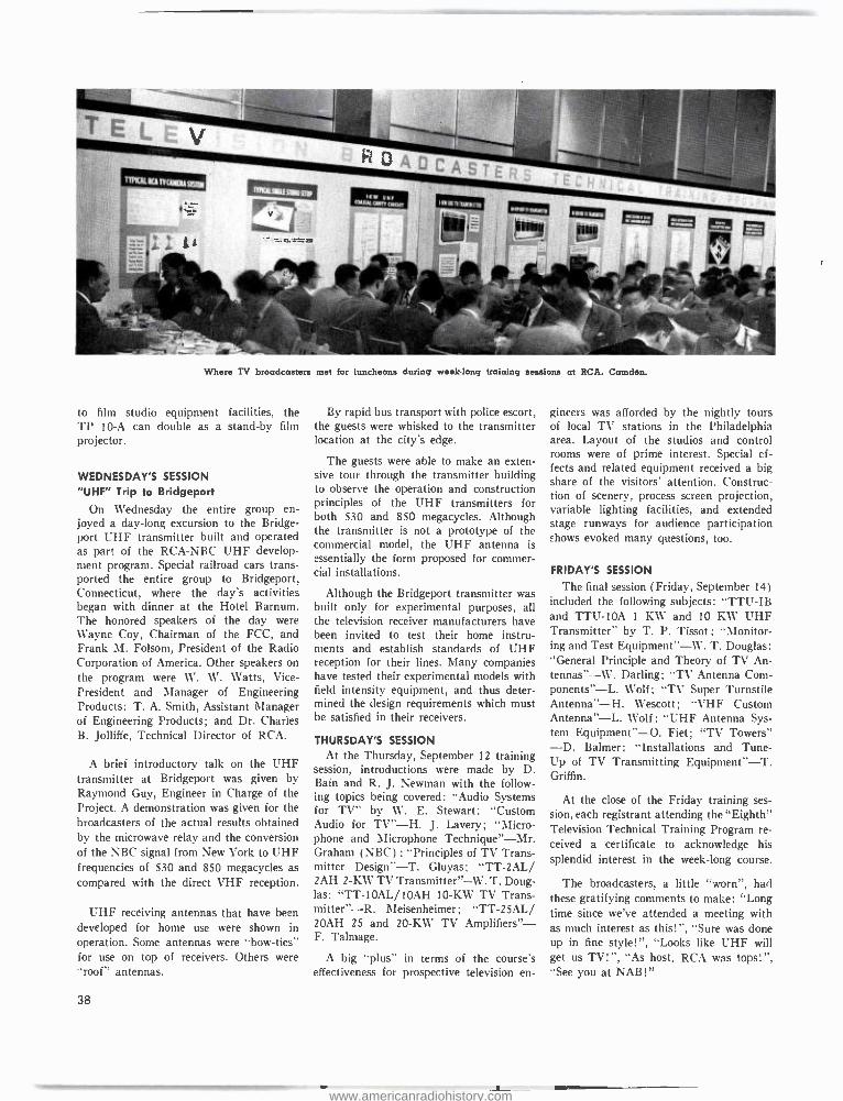
Where TV broadcasters met for luncheons during week -long training sessions at RCA. Camden.
to film studio equipment facilities, the TP 10 -A can double as a stand -by film projector.
WEDNESDAY'S SESSION
"UHF" Trip to Bridgeport
On Wednesday the entire group en- joyed a day -long excursion to the Bridge- port UHF transmitter built and operated as part of the RCA -NBC UHF develop- ment program. Special railroad cars trans- ported the entire group to Bridgeport, Connecticut, where the day's activities began with dinner at the Hotel Barnum. The honored speakers of the day were Wayne Coy, Chairman of the FCC, and Frank M. Folsom, President of the Radio Corporation of America. Other speakers on the program were W. W. Watts, Vice - President and Manager of Engineering Products; T. A. Smith, Assistant Manager of Engineering Products; and Dr. Charles B. Jolliffe, Technical Director of RCA.
A brief introductory talk on the UHF transmitter at Bridgeport was given by Raymond Guy, Engineer in Charge of the Project. A demonstration was given for the broadcasters of the actual results obtained by the microwave relay and the conversion of the NBC signal from New York to UHF frequencies of 530 and 850 megacycles as compared with the direct VHF reception.
UHF receiving antennas that have been developed for home use were shown in operation. Some antennas were "bow- ties" for use on top of receivers. Others were "roof" antennas.
38
By rapid bus transport with police escort, the guests were whisked to the transmitter location at the city's edge.
The guests were able to make an exten- sive tour through the transmitter building to observe the operation and construction principles of the UHF transmitters for both 530 and 850 megacycles. Although the transmitter is not a prototype of the commercial model, the UHF antenna is essentially the form proposed for commer- cial installations.
Although the Bridgeport transmitter was built only for experimental purposes, all the television receiver manufacturers have been invited to test their home instru- ments and establish standards of UHF reception for their lines. Many companies have tested their experimental models with field intensity equipment, and thus deter- mined the design requirements which must be satisfied in their receivers.
THURSDAY'S SESSION
At the Thursday, September 12 training session, introductions were made by D. Bain and R. J. Newman with the follow- ing topics being covered: "Audio Systems for TV" by W. E. Stewart; "Custom Audio for TV " -H. J. Lavery; "Micro- phone and Microphone Technique " -Mr. Graham (NBC) ; "Principles of TV Trans- mitter Design " -T. Gluyas; "TT -2AL/ 2AH 2 -KW TV Transmitter " -W. T. Doug- las; "TT- 10AL /10AH 10 -KW TV Trans- mitter"-R. Meisenheimer; "TT -25AL/ 20AH 25 and 20 -KW TV Amplifiers" - F. Talmage.
A big "plus" in terms of the course's effectiveness for prospective television en-
gineers was afforded by the nightly tours of local TV stations in the Philadelphia area. Layout of the studios and control rooms were of prime interest. Special ef- fects and related equipment received a big share of the visitors' attention. Construc- tion of scenery, process screen projection, variable lighting facilities, and extended stage runways for audience participation shows evoked many questions, too.
FRIDAY'S SESSION
The final session (Friday, September 14) included the following subjects: "TTU -IB and TTU -10A 1 KW and 10 KW UHF Transmitter" by T. P. Tissot : `'Monitor- ing and Test Equipment " -W. T. Douglas: "General Principle and Theory of TV An- tennas"--W. Darling; "TV Antenna Com- ponents"-L. Wolf; "TV Super Turnstile Antenna " -H. Wescott; "VHF Custom Antenna " -L. Wolf ; "UHF Antenna Sys- tem Equipment " -O. Fiet; "TV Towers" -D. Balmer; "Installations and Tune - Up of TV Transmitting Equipment " -T. Griffin.
At the close of the Friday training ses- sion, each registrant attending the "Eighth" Television Technical Training Program re- ceived a certificate to acknowledge his splendid interest in the week -long course.
The broadcasters, a little "worn ", had these gratifying comments to make: "Long time since we've attended a meeting with as much interest as this!", "Sure was done up in fine style! ", "Looks like UHF will get us TV!", "As host, RCA was tops!", "See you at NAB!"
www.americanradiohistory.com
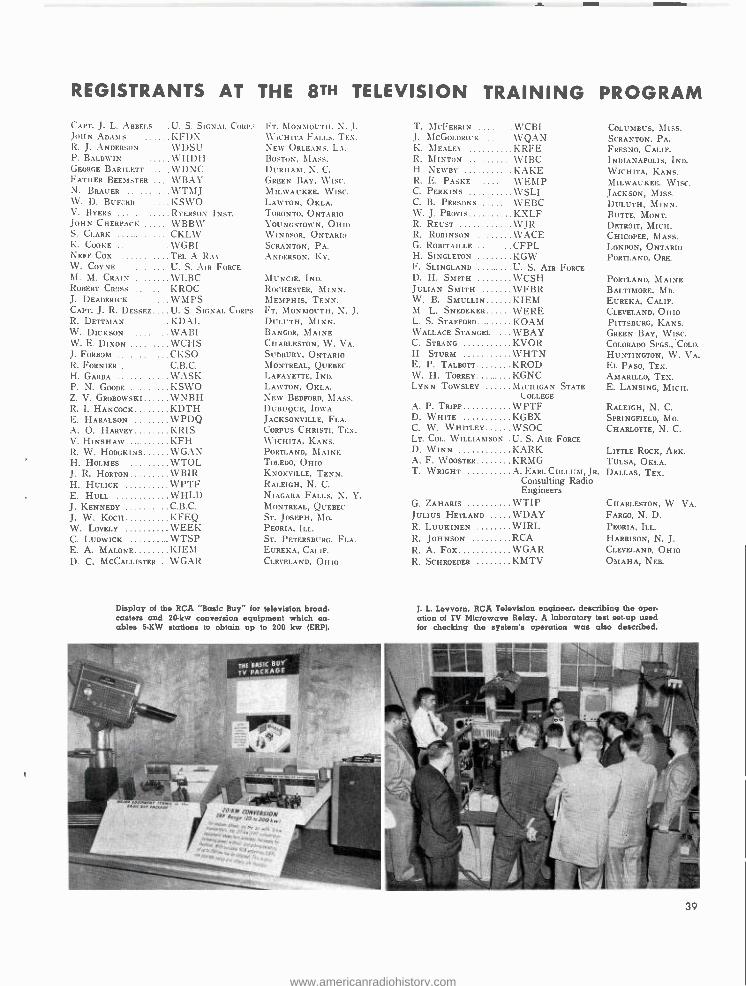
REGISTRANTS AT THE 8TH TELEVISION TRAINING PROGRAM
(.APT. J. L. :\BBF.LS U. S. SIGNAL (_URP.; JOHN ADAMS KFDX R. J. ANDER`:ON .... WDSU P. BALDWIN WHDH GEORGE BARTLETT WDNC FATHER BF.EMSTItR ... WBAY N. BRAUER WTMJ W. D. BUF::RD KSWO V. BYERS RYERSON INST. JOHN CHERPACK WBBW S. CLARK CKLW K. 000KE . . _ . . . . . WGRI NEFF COX TEL A RAY W. COYNE . U. S. AIR FORCE
M. M. CRAIN WLBC ROBERT CiVISS KROC J. DEADERICK WMPS CAPT. J. R. DESSEZ U. S. SIGNAL CORPS R. DETTMAN KDAI. W. DICKSON WABI W. E. DixoN WCHS J. FDRBOM CKSO R. FORNIER C B C H. GARBA WASK P. N. GOODE . . . . . . . KSWO Z. V. GROBOwsKI WNRH R. I. HANCOCK KDTH E. HARALSON WPDQ A. O. HARVEY KRIS V. HINSHAW KFH R. W. HODGKINS WGAN H. HOLMES WTOL J. R. HORTON WEIR H. HULICK WPTF E. HULL WHLD J. KENNEDY . . . ... . . . . C.B.C. J. W. KOCH KFEQ W. LOVELY WEEK C. LUDWICK WTSP E. A. MALONE KIEM D. C. MCCALLISTER. . WGAR
i\IONMUI'TII. N. J. WICHITA FALLS. TEX. NEW ORLEANS, LA. BOSTON, MASS. DURHAM, N. C.
GREEN BAY, WISC. MILWAUKEE, WISC. LAWTON, OKLA. TORONTO. ONTARIO YOUNGSTOWN, OHIO WINDSOR, ONTARIn SCRANTON, PA. ANDERSON. Kr.
MUNCIE, IND. ROCHESTER, MINN. MEMPHIS, TENN. FT. MONMOUTH, N. J. DULUTH, MINN. BANGOR, MAINE CHARLESTON, W. VA. SUDBURY, ONTARIO MONTREAL, QUEBEC LAFAYETTE, IND. LAWTON, OKLA. NEW BEDFORD, MASS. DUBUQUE, IOWA JACKSONVILLE, FLA. CORPUS CHRISTI, TEX. WICHITA, KANS. PORTI.AND, MAINE TOLEDO, OHIO KNOXVILLE, TENN. RALEIGH, N. C. NIAGARA FALLS, N. Y. MONTREAL, QUEBEC
ST. JOSEPH, MO. PEORIA, ILL. ST. PETERSBURG. FLA. EUREKA, CALIF. CLEVELAND, OHIO
Display of the RCA 'Basic Buy" for television broad- casters and 20 -kw conversion equipment which en- ables 5-KW stations to obtain up to 200 kw (ERP).
T. MCFERRIN . -.. WCBI J. cGoLURICK WQAN K. MEALEY KRFE R. MINTON .. ...... WIBC H. NEWRY KAKE R. E. PASKE WEMP C. PERKINS WSLI C. B. PERSONS WEBC W. J. PROVIK KXLF R. REUST WJR R. ROBINSON WACE G. ROBITAILLE CFPL H. SINGLETON KGW F. SLINGLAND U. S. AIR FORCE D. H. SMITH WCSH JULIAN SMITH WFBR W. B. SMULLIN KIEM M. L. SNEDEKER WERE L. S. STAFFORD KOAM WALLACE STANGEL WBAY C. STRANG KVOR H. STURM WHTN E. P. TALBOTT KROD W. H. ToRREY KGNC LYNN TOWSLEY MICHIGAN STATE
COLLEGE
A. P. TRIPP WPTF D. WHITE KGBX C. W. WHITLEY WSOC LT. COL. WILLIAMSON U. S. AIR FORCE
D. WINN KARK A. F. WOOSTER KRMG T. WRIGHT A. EARL CULLUM, JR.
Consulting Radio Engineers
G. ZAHARIS WTIP JULIUS HETLAND WDAY R. LUUKINEN WIRL R. JOHNSON RCA R. A. Fox WGAR R. SCHROEDER KMTV
COLUMBUS, Miss. SCRANTON, PA. FRESNO, CALIF. INDIANAPOLIS, IND. WICHITA, KANS. MILWAUKEE, WISC. JACKSON, MISS. DULUTH, MINN. BUTTE, MONT. DETROIT, MICH. CHICOPEE, MASS. LONDON, ONTARIO PORTLAND, ORE.
PORTLAND, MAINE BALTIMORE, MD. EUREKA, CALIF. CLEVELAND, OHIO PITTSBURG, KANS. GREEN BAY, WISC. COLORADO SPGS., COLO.
HUNTINGTON, W. VA. EL PASO, TEX. AMARILLO, TEX. E. LANSING, MICH.
RALEIGH, N. C. SPRINGFIELD, M0. CHARLOTTE, N. C.
LITTLE RocK, ARK. TULSA, OKLA. DALLAS, TEX.
CHARLESTON, W. VA. FARGO, N. D. PEORIA, ILL.
HARRISON, N. J. CLEVELAND, OHIO OMAHA, NEB.
J. L. Lovvorn, RCA Television engineer, describing the oper- ation of TV Microwave Relay. A laboratory test set -up used for checking the system's operation was also described.
39
www.americanradiohistory.com
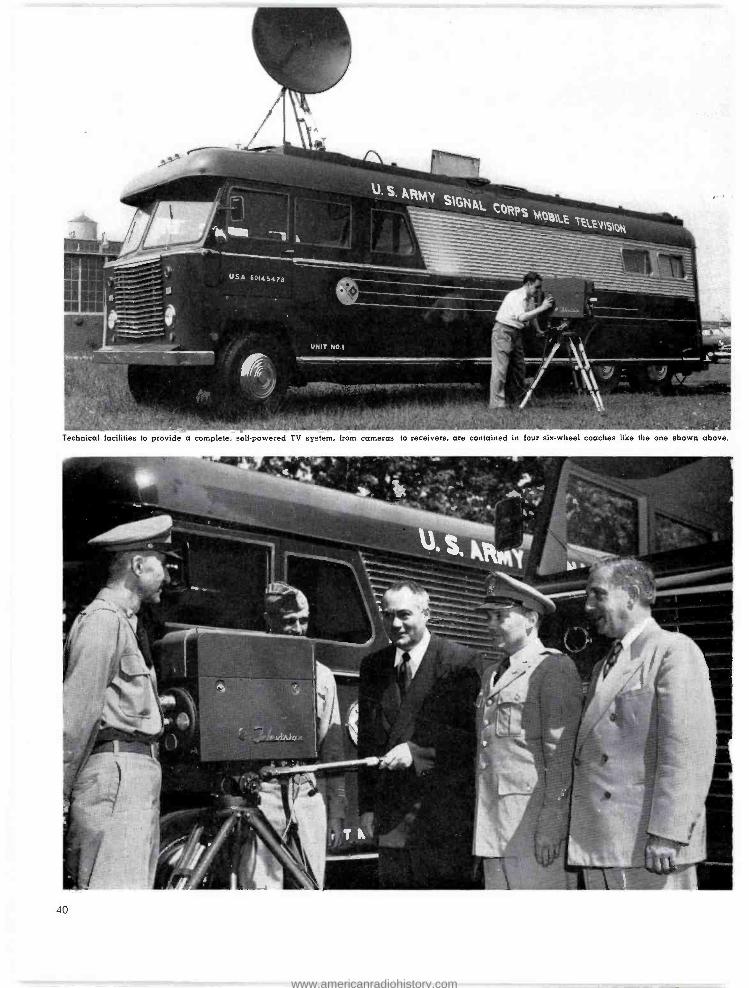
Technical facilities to provide a complete, self -powered TV system, from cameras to receivers, are contained in four six -wheel coaches like the one shown above.
40
www.americanradiohistory.com
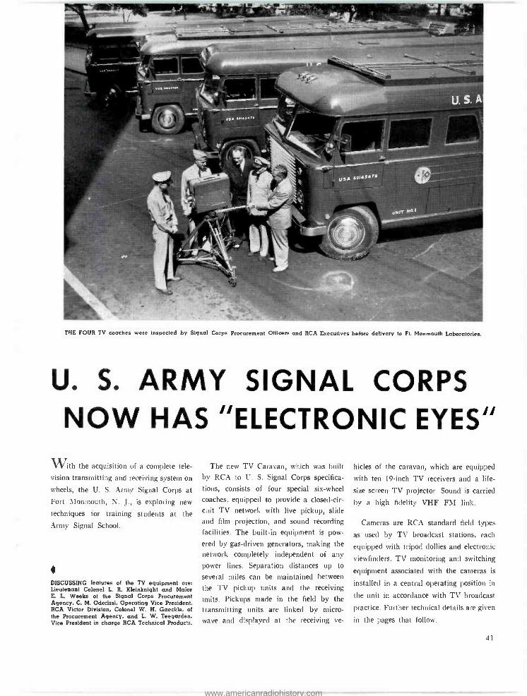
THE FOUR TV coaches were inspected by Signal Corps Procurement Officers and RCA Executives before delivery to Ft. Monmouth Laboratories.
U. S. ARMY SIGNAL CORPS NOW HAS "ELECTRONIC EYES"
With the acquisition of a complete tele-
vision transmitting and receiving system on
wheels, the U. S. Army Signal Corps at Fort Monmouth, N. J., is exploring new
techniques for training students at the
Army Signal School.
DISCUSSING features of the TV equipment are: Lieutenant Colonel L. R. Kleinknight and Major E. L. Weeks of the Signal Corps Procurement Agency, C. M. Odorizzi, Operating Vice President, RCA Victor Division, Colonel W. H. Gaeckle, of the Procurement Agency, and L. W. Teegarden, Vice President in charge RCA Technical Products.
The new TV Caravan, which was built by RCA to U. S. Signal Corps specifica-
tions, consists of four special six -wheel
coaches, equipped to provide a closed -cir-
cuit TV network with live pickup, slide and film projection, and sound recording
facilities. The built -in equipment is pow-
ered by gas- driven generators, making the network completely independent of any
power lines. Separation distances up to
several miles can be maintained between
the TV pickup units and the receiving
units. Pickups made in the field by the
transmitting units are linked by micro-
wave and displayed at the receiving ve-
hides of the caravan, which are equipped
with ten 19 -inch TV receivers and a life -
size screen TV projector. Sound is carried
by a high fidelity VHF FM link.
Cameras are RCA standard field types
as used by TV broadcast stations, each
equipped with tripod dollies and electronic
viewfinders. TV monitoring and switching
equipment associated with the cameras is
installed in a central operating position in
the unit in accordance with TV broadcast
practice. Further technical details are given
in the pages that follow.
41
www.americanradiohistory.com
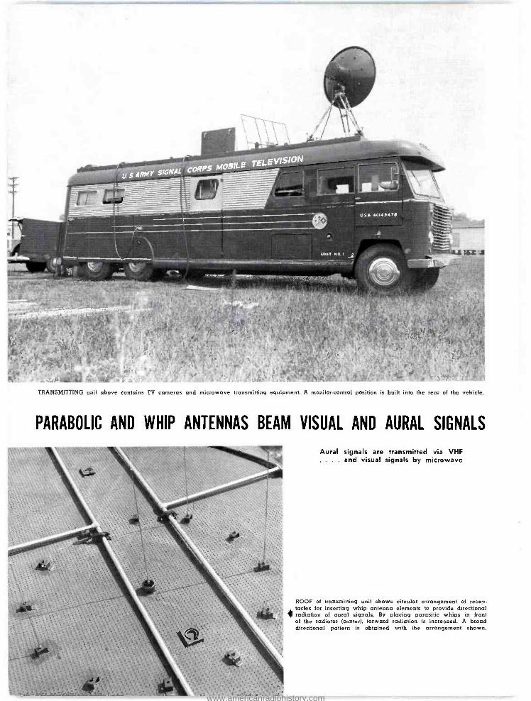
...,.".:J _1!},...TV.I..,....:4eu'f4.?p*
TRANSMITTING unit above contains TV cameras and microwave transmitting equipment. A monitor.control position is built into the rear of the vehicle.
PARABOLIC AND WHIP ANTENNAS BEAM VISUAL AND AURAL SIGNALS
Aural signals are transmitted via VHF . . and visual signals by microwave
ROOF of transmitting unit shows circular arrangement of rece,. tacles for inserting whip antenna elements to provide directional
« radiation of aural signals. By placing parasitic whips in front of the radiator (center). forward radiation is increased. A broad directional pattern is obtained with the arrangement shown.
www.americanradiohistory.com
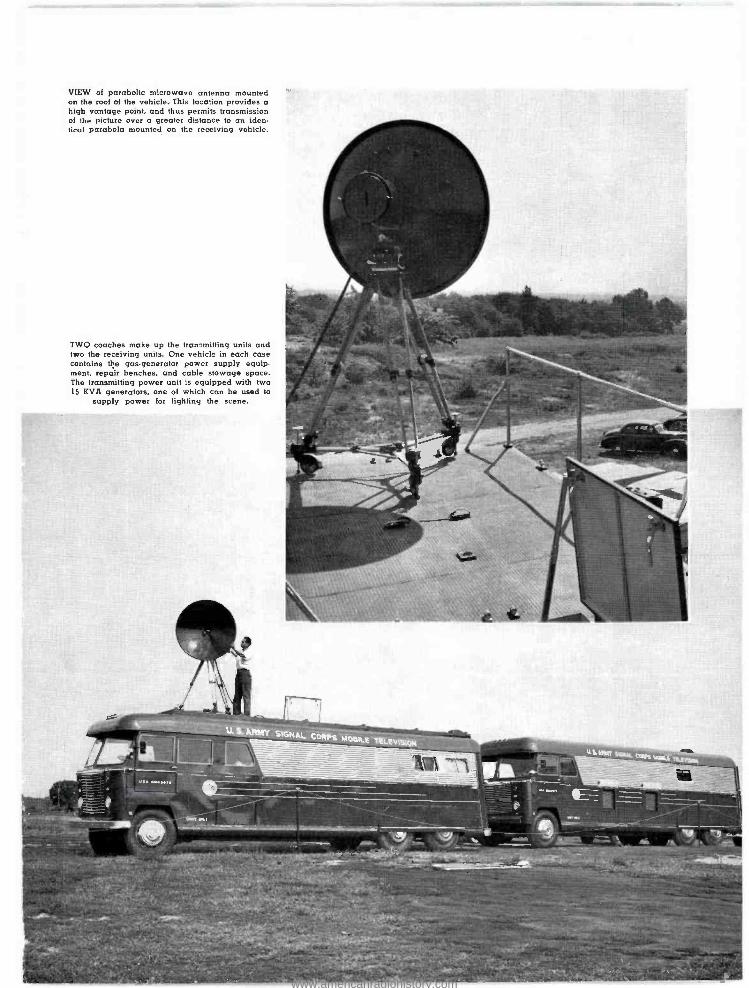
VIEW of parabolic microwave antenna mounted on the roof of the vehicle. This location provides a high vantage point, and thus permits transmission of the picture over a greater distance to an iden- tical parabola mounted on the receiving vehicle.
TWO coaches make up the tran-Lmitling units and two the receiving units. One vehicle in each case contains the gas-generator power supply equip- ment, repair benches, and cable stowage space. The transmitting power unit is equipped with two 15 KVA generators. one of which can be used to
supply power for lighting the scene.
'401P4"%.,1!
www.americanradiohistory.com
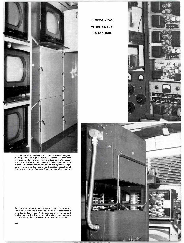
IN THE receiver display unit, shock- mounted compart- ments provide storage for ten RCA 19 -inch TV receivers for transport to various receiving locations. For opera- tion, the receivers are removed, Interconnected and placed on special dollies shown on the opposite page. Cables stored in the power unit provide operation of the receivers up to 500 feet from the receiving vehicle.
THE receiver display unit houses a 16mm TV projector. film camera and slide projector, which are permanently installed in the coach. A life -size screen projector and folding screen (visible at top of picture) are removed
and set up for operation at the desired lo_ation.
44
INTERIOR VIEWS
OF THE RECEIVER
DISPLAY UNITS
www.americanradiohistory.com
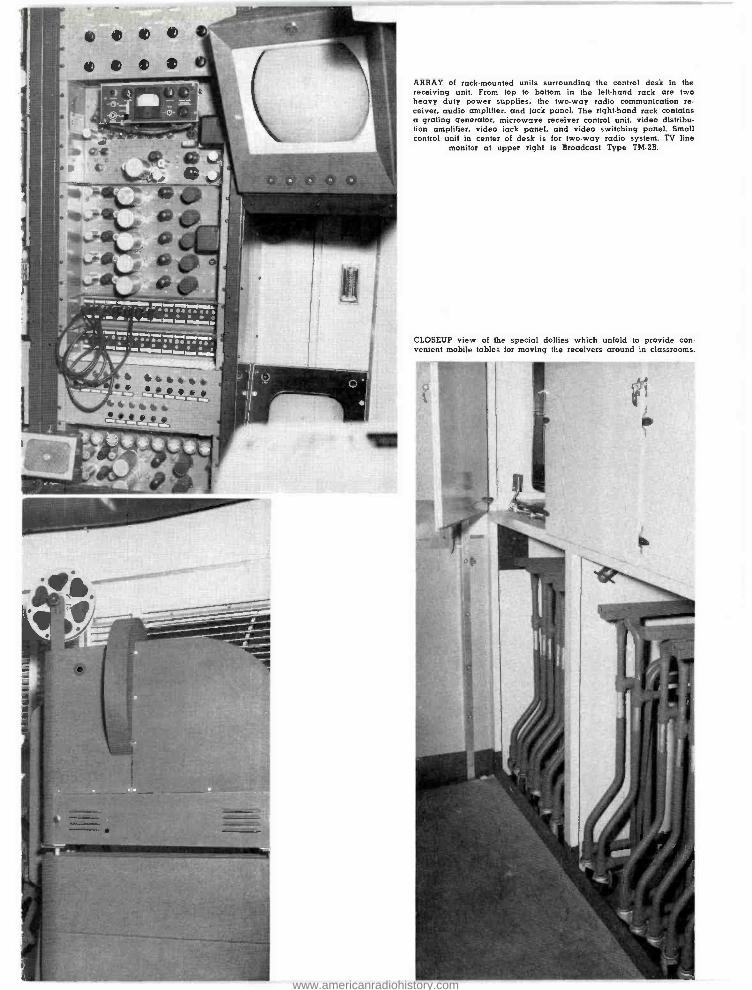
ARRAY of rack -mounted units surrounding the control desk in the receiving unit. From top to bottom in the left -hand rack are two heavy duty power supplies, the two -way radio communication re- ceiver, audio amplifier. and lack panel. The right -hand rack contains a grating generator, microwave receiver control unit, video dlstribu- lion amplifier, video lack panel, and video switching panel. Small control unit in center of desk is for two -way radio system. TV line
monitor at upper right is Broadcast Type TM -2B.
CLOSEUP view of the special dollies which unfold to provide con- venient mobile tables for moving the receivers around in classrooms.
www.americanradiohistory.com
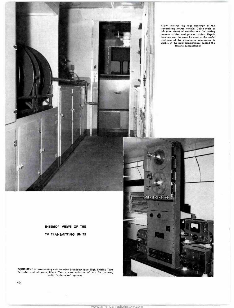
VIEW through the rear doorway of the transmitting power vehicle. Cable reels at left (and right) of corridor are for storing camera cables and power cables. Repair benches can be seen forward of the reels. and one of the gas- engine generators is visible in the next compartment behind the
driver's compartment.
INTERIOR VIEWS OF THE
TV TRANSMITTING UNITS
EQUIPMENT in transmitting unit includes broadcast type High Fidelity Tape Recorder and mixer -amplifiers. Two control units at left are for two -way
radio "order- wire" systems.
46
www.americanradiohistory.com
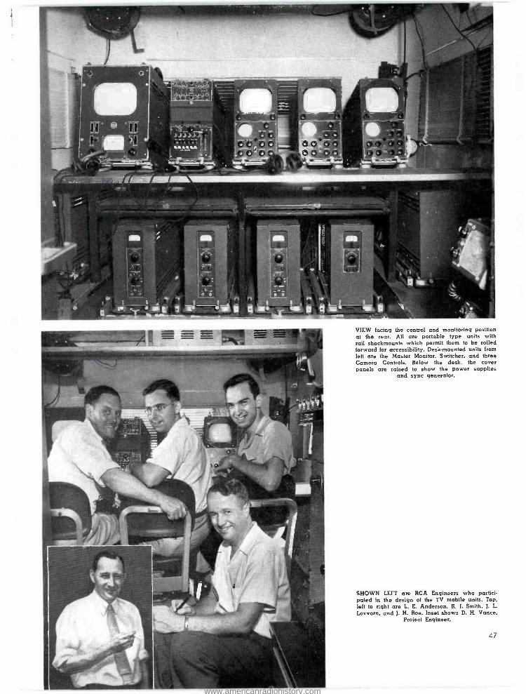
'húú ' uu; ..,_ 9UU-V V %
i
e, a
! >A. fs n "i j. VIEW facing the control and monitoring position at the rear. All are portable type units with rail shockmounts which permit them to be rolled forward for accessibility. Desk -mounted units from left are the Master Monitor, Switcher, and three Camera Controls. Below the desk, the cover panels are raised to show the power supplies
and sync generator.
SHOWN LEFT are RCA Engineers who partici- pated in the design of the TV mobile units. Top, left to right are L. E. Anderson, R. J. Smith, J. L.
Lovvorn, and J. H. Roe. Inset shows D. H. Vance, Project Engineer.
47
www.americanradiohistory.com
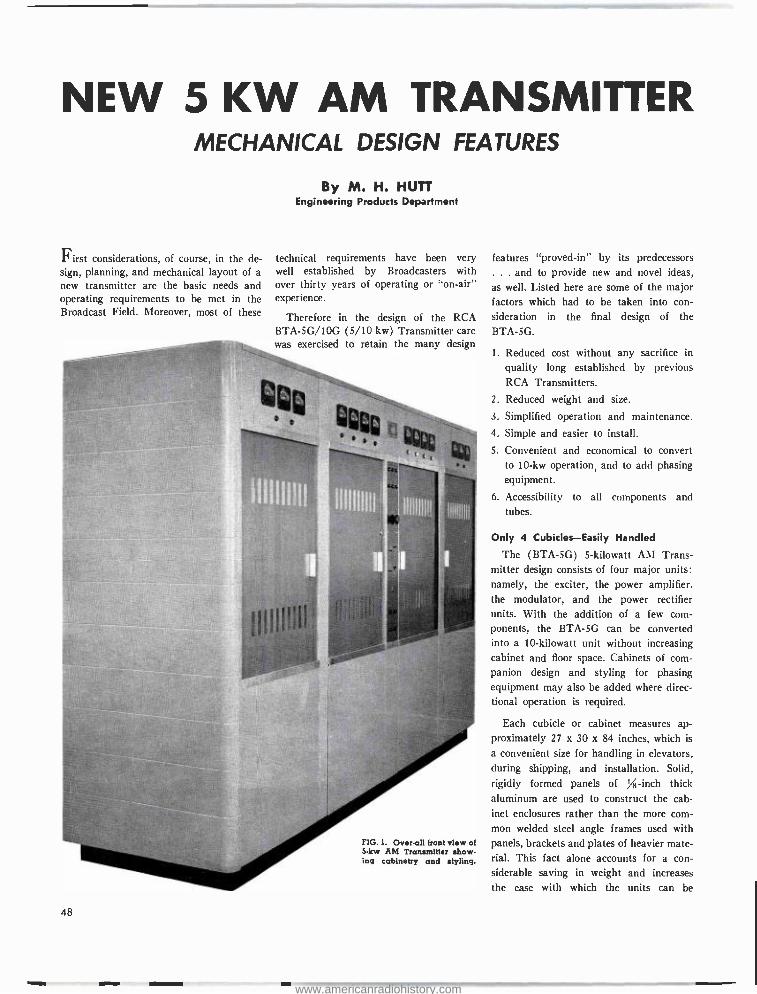
NEW 5 KW AM TRANSMITTER MECHANICAL DESIGN FEATURES
First considerations, of course, in the de- sign, planning, and mechanical layout of a new transmitter are the basic needs and operating requirements to be met in the Broadcast Field. Moreover, most of these
By M. H. HUTT Engineering Products Department
technical requirements have been very well established by Broadcasters with over thirty years of operating or "on -air" experience.
Therefore in the design of the RCA BTA- 5G /10G (5/10 kw) Transmitter care was exercised to retain the many design
4 s
FIG. 1. Over -all front view of 5 -kw AM Transmitter show- ing cabinetry and styling.
features "proved -in" by its predecessors ... and to provide new and novel ideas,
as well. Listed here are some of the major factors which had to be taken into con- sideration in the final design of the BTA -5G.
1. Reduced cost without any sacrifice in
quality long established by previous RCA Transmitters.
2. Reduced weight and size.
3. Simplified operation and maintenance.
4. Simple and easier to install.
5. Convenient and economical to convert to 10 -kw operation, and to add phasing equipment.
6. Accessibility to all components and tubes.
Only 4 Cubicles -Easily Handled
The (BTA -5G) 5- kilowatt AM Trans- mitter design consists of four major units: namely, the exciter, the power amplifier. the modulator, and the power rectifier units. With the addition of a few com- ponents, the BTA -5G can be converted into a 10- kilowatt unit without increasing cabinet and floor space. Cabinets of corn -
panion design and styling for phasing equipment may also be added where direc- tional operation is required.
Each cubicle or cabinet measures ap- proximately 27 x 30 x 84 inches, which is
a convenient size for handling in elevators, during shipping, and installation. Solid, rigidly formed panels of % -inch thick aluminum are used to construct the cab- inet enclosures rather than the more corn-
mon welded steel angle frames used with panels, brackets and plates of heavier mate- rial. This fact alone accounts for a con- siderable saving in weight and increases the ease with which the units can be
www.americanradiohistory.com
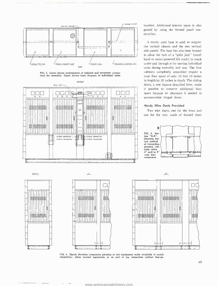
{
STATION GROUND
4601)140 STRAPS
[ =----
s
_--
f
- - _ _-- ----
i - - - -
`_ - - - -- - ----
LuOO1)LATOa UNIT -POWER APPPLIONER UNIT
TOP
-fAC1TeR UNIT P[CTrIiFP i CO14TPOl ow/
FIG. 2. Lower shows arrangement of cabinets and necessary connec- tions for assembly. Upper shows base diagram of individual units.
FRONT TERM 276
_ 00 0 0
000 0 0 0
.- 000 - 0 0 0 0 0
o
0000000000
0000000000
_
-
_
-
0000000000
0000000000
O
0
000 000
0; o
:: 0
0 0
0000000000
0
00000[0000
-
-
00000001100
0000000000
0
-.
VA-0'
a POMT coa14ec*oa .Ii e POaT COHaeCTOR
'F` O
Po ST coa14 cTOa
\-e Po aT COaaeCiOR
SINGLE
r-
a
a
a
a
0
0
a
a
a
a
a
a
a
a
o
a
a
o
o
a
o
handled. Additional interior space is also
gained by using the formed panel con-
struction.
A sturdy steel base is used to support the vertical chassis and the two vertical side panels. The base has also been formed
to allow the fork of a "pilot jack" (small hand or motor -powered lift truck) to reach
under and through it for moving individual units during assembly and test. The four cabinets completely assembled require a
total floor space of only 10 feet 10 inches in length by 30 inches in depth. The sliding doors, a new feature described later, make it possible to conserve additional floor
space because no clearance is needed to
accommodate hinged doors.
Handy Wire Ducts Provided
Two wire ducts, one for the front and one for the rear, nlacle of formed sheet
FIG. 3. Sec - lion "A -A ". showing typ- ical method of connecting phasing cab- inets using 4" and /or 8" wire duct connectors.
8
a 0
0
o
a
a
o
o
0 0
a
o
0
o
o
0
o
a
a
0
a
a
o
a
o
ao
a
a
0
o
0
o
o
o 0
FIG. 4. Sketch showing companion phasing or test equipment racks available to match transmitter: either located separately or as part of the transmitter cabinet line -up.
49
www.americanradiohistory.com
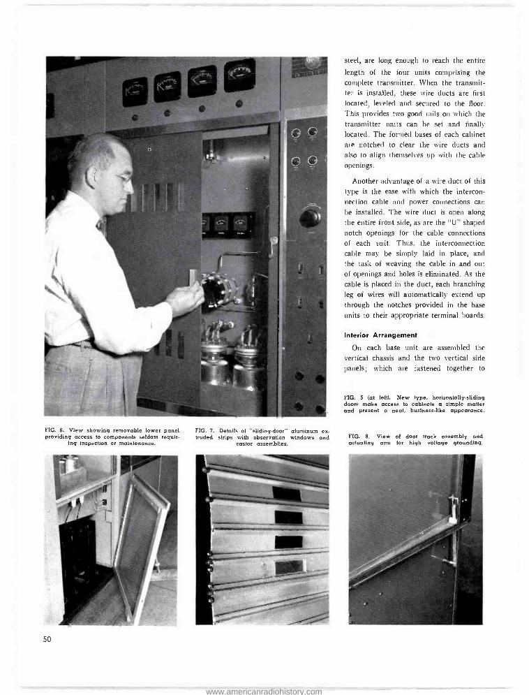
FIG. 6. View showing removable lower panel providing access to components seldom requir-
ing inspection or maintenance.
50
FIG. 7. Details of "sliding -door" aluminum ex- truded strips with observation windows and
castor assemblies.
steel, are long enough to reach the entire
length of the four units comprising the
complete transmitter. When the transmit- ter is installed, these wire ducts are first located, leveled and secured to the floor. This provides two good rails on which the
transmitter units can be set and finally located. The formed bases of each cabinet are notched to clear the wire ducts and
also to align themselves up with the cable
openings.
Another advantage of a wire duct of this
type is the ease with which the intercon- nection cable and power connections can
be installed. The wire duct is open along
the entire front side, as are the "U" shaped
notch openings for the cable connections
of each unit. Thus, the interconnection cable may be simply laid in place, and
the task of weaving the cable in and out of openings and holes is eliminated. As the
cable is placed in the duct, each branching leg of wires will automatically extend up
through the notches provided in the base
units to their appropriate terminal boards.
Interior Arrangement
On each base unit are assembled the
vertical chassis and the two vertical side
panels; which are fastened together to
FIG. 5 (at left). New type, horizontally -sliding doors make access to cabinets a simple matter and present a neat, businesslike appearance.
FIG. 8. View of door track assembly and actuating arm for high voltage grounding.
www.americanradiohistory.com
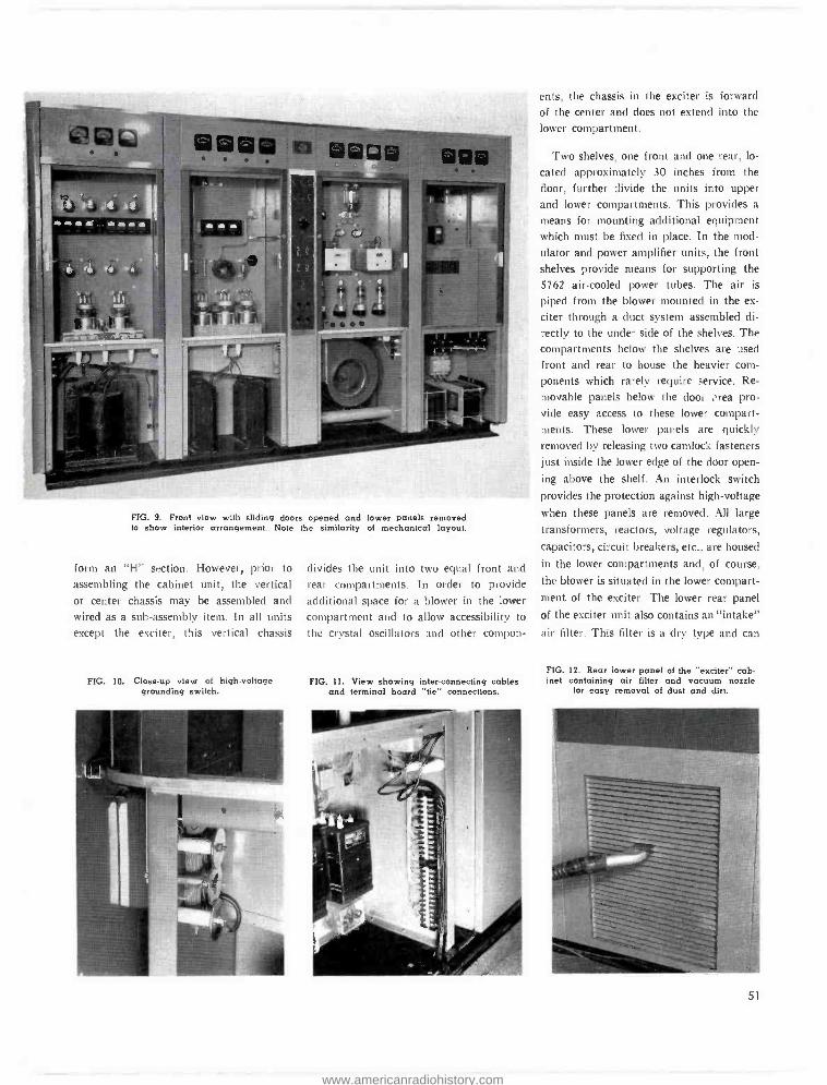
FIG. 9. Front view with sliding doors opened and lower panels removed to show interior crrangement. Note the similarity of mechanical layout.
form an "H" section. However, prior to
assembling the cabinet unit, the vertical or center chassis may be assembled and wired as a sub -assembly item. In all units except the exciter, this vertical chassis
FIG. 10. Close -up view of high -voltage grounding switch.
divides the unit into two equal front and rear compartments. In order to provide additional space for a blower in the lower compartment and to allow accessibility to
the crystal oscillators and other compon-
FIG. 11. View showing interconnecting cables and terminal board -tie" connections.
ents, the chassis in the exciter is forward
of the center and does not extend into the
lower compartment.
Two shelves, one front and one rear, lo-
cated approximately 30 inches from the
floor, further divide the units into upper and lower compartments. This provides a
means for mounting additional equipment which must be fixed in place. In the mod-
ulator and power amplifier units, the front
shelves provide means for supporting the 5762 air -cooled power tubes. The air is
piped from the blower mounted in the ex-
citer through a duct system assembled di-
rectly to the under side of the shelves. The compartments below the shelves are used
front and rear to house the heavier com-
ponents which rarely require service. Re-
movable panels below the door : rea pro- vide easy access to these lower compart- ments. These lower panels are quickly removed by releasing two camlock fasteners just inside the lower edge of the door open-
ing above the shelf. An interlock switch provides the protection against high -voltage
when these panels are removed. All large
transformers, reactors, voltage regulators. capacitors, circuit breakers, etc., are housed
in the lower compartments and, of course,
the blower is situated in the lower compart-
ment of the exciter. The lower rear panel
of the exciter unit also contains an "intake"
air filter. This filter is a dry type and can
FIG. 12. Rear lower panel of the "exciter" cab- inet containing air filter and vacuum nozzle
for easy removal of dust and dirt. MM.
51
www.americanradiohistory.com
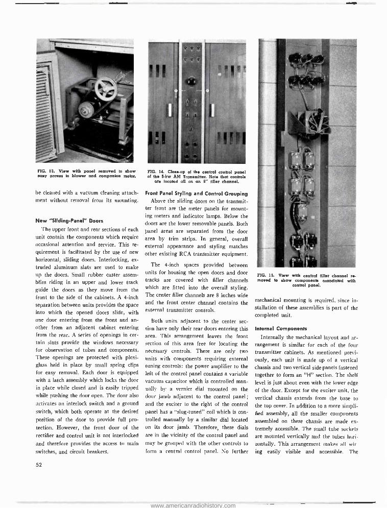
FIG. 13. View with panel removed to show easy access to blower and companion motor.
be cleaned with a vacuum cleaning attach- ment without removal from its mounting.
New "Sliding -Panel" Doors
The upper front and rear sections of each unit contain the components which require occasional attention and service. This re-
quirement is facilitated by the use of new
horizontal, sliding doors. Interlocking, ex-
truded aluminum slats are used to make up the doors. Small rubber caster assem- blies riding in an upper and lower track guide the doors as they move from the front to the side of the cabinets. A 4 -inch separation between units provides the space into which the opened doors slide, with one door entering from the front and an- other from an adjacent cabinet entering from the rear. A series of openings in cer- tain slats provide the windows necessary for observation of tubes and components. These openings are protected with plexi- glass held in place by small spring clips for easy removal. Each door is equipped with a latch assembly which locks the door in place while closed and is easily tripped while pushing the door open. The door also
activates an interlock switch and a ground
switch, which both operate at the desired
position of the door to provide full pro-
tection. However, the front door of the
rectifier and control unit is not interlocked
and therefore provides the access to main
switches, and circuit breakers.
52
FIG. 14. Close -up of the central control panel of the 5 -kw AM Transmitter. Note that controls
are located all on an 8- filler channel.
Front Panel Styling and Control Grouping Above the sliding doors on the transmit-
ter front are the meter panels for mount- ing meters and indicator lamps. Below the doors are the lower removable panels. Both panel areas are separated from the door area by trim strips. In general, overall external appearance and styling matches other existing RCA transmitter equipment.
The 4 -inch spaces provided between units for housing the open doors and door tracks are covered with filler channels which are fitted into the overall styling. The center filler channels are 8 inches wide and the front center channel contains the external transmitter controls.
Both units adjacent to the center sec- tion have only their rear doors entering this area. This arrangement leaves the front section of this area free for locating the necessary controls. There are only two units with components requiring external tuning controls: the power amplifier to the left of the control panel contains a variable vacuum capacitor which is controlled man- ually by a vernier dial mounted on the door jamb adjacent to the control panel; and the exciter to the right of the control panel has a "slug- tuned" coil which is con- trolled manually by a similar dial located on its door jamb. Therefore, these dials are in the vicinity of the control panel and may be grouped with the other controls to
form a central control panel. No further
FIG. 15. View with central filler channel re- moved to show components associated with
control panel.
mechanical mounting is required, since in- stallation of these assemblies is part of the completed unit.
Internal Components
Internally the mechanical layout and ar- rangement is similar for each of the four transmitter cabinets. As mentioned previ- ously, each unit is made up of a vertical chassis and two vertical side panels fastened together to form an "H" section. The shelf level is just about even with the lower edge of the door. Except for the exciter unit, the vertical chassis extends from the base to
the top cover. In addition to a more simpli- fied assembly, all the smaller components assembled on these chassis are made ex- tremely accessible. The small tube sockets are mounted vertically and the tubes hori- zontally. This arrangement makes all wir
ing easily visible and accessible. The
www.americanradiohistory.com
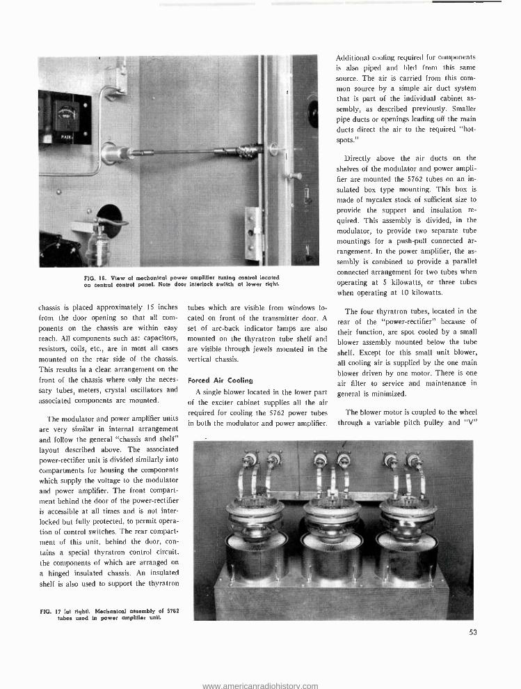
FIG. 16. View of mechanical power amplifier tuning control located on central control panel. Note door interlock switch at lower right.
chassis is placed approximately 15 inches
from the door opening so that all com-
ponents on the chassis are within easy
reach. All components such as: capacitors,
resistors, coils, etc., are in most all cases
mounted on the rear side of the chassis.
This results in a clean arrangement on the
front of the chassis where only the neces-
sary tubes, meters, crystal oscillators and
associated components are mounted.
The modulator and power amplifier units
are very similar in internal arrangement
and follow the general "chassis and shelf"
layout described above. The associated
power- rectifier unit is divided similarly into
compartments for housing the components
which supply the voltage to the modulator
and power amplifier. The front compart- ment behind the door of the power- rectifier
is accessible at all times and is not inter-
locked but fully protected, to permit opera-
tion of control switches. The rear compart-
ment of this unit, behind the door, con-
tains a special thyratron control circuit.
the components of which are arranged on
a hinged insulated chassis. An insulated
shelf is also used to support the thyratron
FIG. 17 (at tight). Mechanical assembly of 5762 tubes used in power amplifier unit.
tubes which are visible from windows lo-
cated on front of the transmitter door. A
set of arc -back indicator lamps are also
mounted on the thyratron tube shelf and are visible through jewels mounted in the vertical chassis.
Forced Air Cooling
A single blower located in the lower part of the exciter cabinet supplies all the air required for cooling the 5762 power tubes in both the modulator and power amplifier.
Additional cooling required for components
is also piped and bled from this same
source. The air is carried from this com-
mon source by a simple air duct system that is part of the individual cabinet as-
sembly, as described previously. Smaller
pipe ducts or openings leading off the main
ducts direct the air to the required "hot - spots."
Directly above the air ducts on the
shelves of the modulator and power ampli-
fier are mounted the 5762 tubes on an in-
sulated box type mounting. This box is
made of mycalex stock of sufficient size to
provide the support and insulation re-
quired. This assembly is divided, in the
modulator, to provide two separate tube
mountings for a push -pull connected ar-
rangement. In the power amplifier, the as-
sembly is combined to provide a parallel
connected arrangement for two tubes when
operating at 5 kilowatts, or three tubes
when operating at 10 kilowatts.
The four thyratron tubes, located in the
rear of the "power- rectifier" because of
their function, are spot cooled by a small
blower assembly mounted below the tube
shelf. Except for this small unit blower,
all cooling air is supplied by the one main
blower driven by one motor. There is one
air filter to service and maintenance in
general is minimized.
The blower motor is coupled to the wheel
through a variable pitch pulley and "V"
53
www.americanradiohistory.com
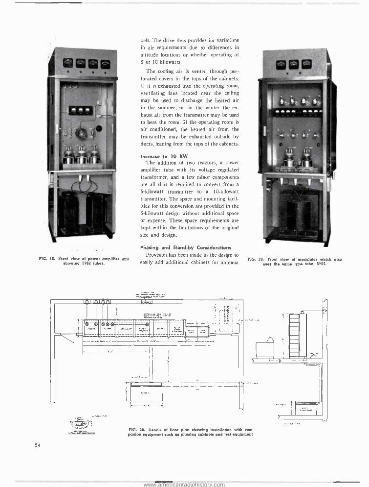
FIG. 18. Front view of power amplifier unit showing 5762 tubes.
54
belt. The drive thus provides for variations in air requirements due to differences in
altitude locations or whether operating at 5 or 10 kilowatts.
The cooling air is vented through per- forated covers in the tops of the cabinets. If it is exhausted into the operating room,
ventilating fans located near the ceiling
may be used to discharge the heated air in the summer, or, in the winter the ex-
haust air from the transmitter may be used to heat the room. If the operating room is
air conditioned, the heated air from the transmitter may be exhausted outside by ducts, leading from the tops of the cabinets.
Increase to 10 KW The addition of two reactors, a power
amplifier tube with its voltage regulated transformer, and a few minor components are all that is required to convert from a
5- kilowatt transmitter to a 10- kilowatt transmitter. The space and mounting facil- ities for this conversion are provided in the 5- kilowatt design without additional space or expense. These space requirements are kept within the limitations of the original size and design.
Phasing and Stand -by Considerations Provision has been made in the design to
easily add additional cabinets for antenna
MarlieOw MN<
FIG. 19. Front view of modulator which also uses the same type tube. 5762.
nM.iouc t04.WC os FIG. 20. Details of floor plan showing installation with com- panion equipment such as phasing cabinets and test equipment
www.americanradiohistory.com
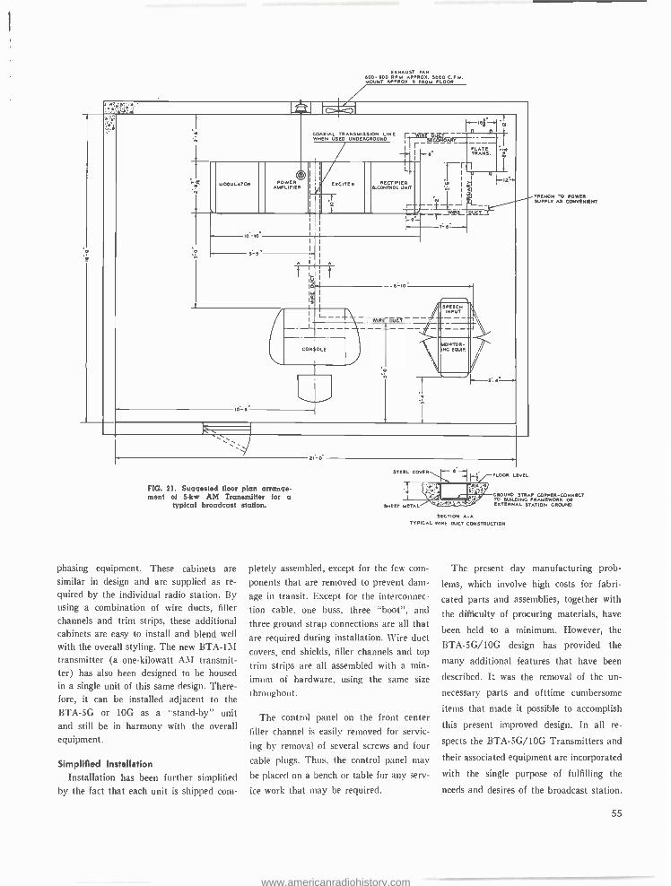
EXHAUST PAN 600-600 RIM APPROX. 5000 C.P.A. MOUNT APPROX. 9 FROM FLOOR
` 6 y 1
fi äYr i C .; 1 isf I .ÿ
COAXIAL TRANSMISSION LINE WE IR N WHEN USED UNDERGROUND
-1.
1
3E A
l.- 6- TRANS.
u00uLAiow POwER AMPLIFIER
I
I
EXCITER
I
Lr
RECTIFIER &CONTROLUNIT
r- _E....-
II
. Ì
.t_J wJ
Ilt l i
12
L_ uq e
I T-6
l----f Ió IÓ I
I
0 6 r A I I A
I t a O. 10
B
SP CH
It I L--
/I -WM lltT--- I
NEEPYT ---I _ _ - - -
CONjOLE II
--- ---/ / I ---I NROR-
INC EQUIP
o \
I0 6 Ì
21. Ó
FIG. 21. Suggested floor plan arrange- ment of 5 -kw AM Transmitter for a
typical broadcast station.
phasing equipment. These cabinets are similar in design and are supplied as re- quired by the individual radio station. By using a combination of wire ducts, filler
channels and trim strips, these additional cabinets are easy to install and blend well
with the overall styling. The new BTA -1M transmitter (a one -kilowatt AM transmit- ter) has also been designed to be housed in a single unit of this same design. There- fore, it can be installed adjacent to the BTA -5G or 10G as a "stand -by" unit and still be in harmony with the overall equipment.
Simplified Installation Installation has been further simplified
by the fact that each unit is shipped com-
FLOOR LEVEL
TRENCH TO POWER SUPPLY AS CONVENIENT
GROUND STRAP COPPER -CONNECT TO BUILDING FRAMEWORK OR EXTERNAL STATION GROUND
SECTION A.A TYPICAL WIRE OUCT CONSTRUCTION
pletely assembled, except for the few com-
ponents that are removed to prevent dam-
age in transit. Except for the interconnec-
tion cable, one buss, three "boot ", and three ground strap connections are all that are required during installation. Wire duct covers, end shields, filler channels and top
trim strips are all assembled with a min -
imum of hardware, using the same size
throughout.
The control panel on the front center
filler channel is easily removed for servic-
ing by removal of several screws and four
cable plugs. Thus, the control panel may
be placed on a bench or table for any serv-
ice work that may be required.
The present day manufacturing prob-
lems, which involve high costs for fabri-
cated parts and assemblies, together with
the difficulty of procuring materials, have
been held to a minimum. However, the
BTA- 5G/10G design has provided the
many additional features that have been
described. It was the removal of the un-
necessary parts and ofttime cumbersome
items that made it possible to accomplish
this present improved design. In all re-
spects the BTA- 5G/10G Transmitters and
their associated equipment are incorporated
with the single purpose of fulfilling the
needs and desires of the broadcast station.
55
www.americanradiohistory.com
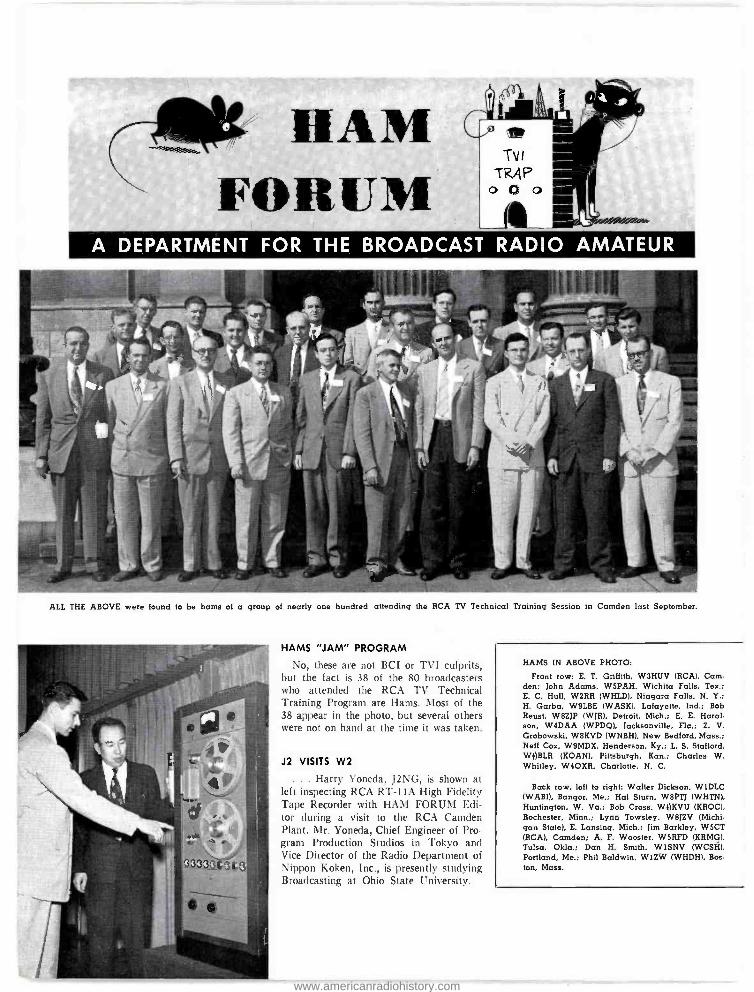
cliOt HAM FORUM
A DEPARTMENT FOR THE BROADCAST RADIO AMATEUR
ALL THE ABOVE were found to be hams of a group of nearly one hundred attending the RCA TV Technical Training Session in Camden last September.
HAMS "JAM" PROGRAM
No, these are not BCI or TVI culprits. but the fact is 38 of the 80 broadcasters who attended the RCA TV Technical Training Program are Hams. Most of the 38 appear in the photo, but several others were not on hand at the time it was taken.
J2 VISITS W2
. . . Harry Yoneda, JING, is shown at left inspecting RCA RT -IlA High Fidelity Tape Recorder with HAM FORUM Edi- tor during a visit to the RCA Camden Plant. Mr. Yoneda, Chief Engineer of Pro- gram Production Studios in Tokyo and Vice Director of the Radio Department of Nippon Koken, Inc., is presently studying liroadcasting at Ohio State University.
HAMS IN ABOVE PHOTO:
Front row: E. T. Griffith, W3HUV (RCA), Cam- den; John Adams. W5PAH, Wichita Falls, Tex.; E. C. Hull, W2RR (WHLD), Niagara Falls, N. Y.: H. Garba, W9LBE (WASK). Lafayette, Ind.; Bob Reust. WBZJP (WJR). Detroit. Mich.; E. E. Haral- son, W4DAA (WPDQ), Jacksonville. Fla.; Z. V. Grobowski, WBKVD (WNBH), New Bedford, Mass.; Neff Cox, W9MDX, Henderson. Ky.; L. S. Stafford. WOBLR (KOAN), Pittsburgh, Kan.; Charles W. Whitley, W4OXR, Charlotte, N. C.
Back row, left to right: Walter Dickson, W1DLC (WABI), Bangor, Me.; Hal Sturn, W8PTI (WHTN). Huntington, W. Va.; Bob Cross, WiiKVU (KROC), Rochester, Minn.; Lynn Towsley, WBJZV (Michi- gan State), E. Lansing. Mich.: Jim Barkley, W5CT (RCA), Camden; A. F. Wooster, W5RFD (KRMG). Tulsa, Okla.; Dan H. Smith, W1SNV (WCSH), Portland, Me.: Phil Baldwin, W1ZW (WHDH). Bos. ton, Mass.
www.americanradiohistory.com
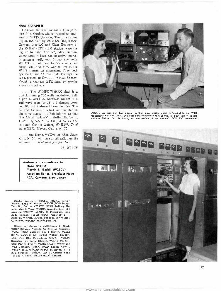
HAM PARADISE!
Here you see what we call a ham para- dise. Mrs. Gordon, who is transmitter oper- ator at WTJS, Jackson, Tenn., is calling CQ on the ham rig while her OM, Robert Gordon, W4HXC and Chief Engineer of the 50 KW (ERP) FM station keeps the log up to date. You see, Mrs. Gordon, whose name is Inez, has an active interest in amateur radio too; in fact she holds W4HPO in addition to her commercial ticket. Mr. and Mrs. Gordon live in the WTJS transmitter apartment. They both operate 20 and 75 fone, but Bob says the XYL prefers 40 CW.... It must be won- derful to hear the XYL insist on staying home to work dx!
. , . The W4HPO -W4HXC final is a
304TL running 700 watts, modulated with a pair of 304TL's. Antennas consist of a
full wave zepp for 75, a 3- element bean for 20, and 4- element beam for ten. The 3- and 4- element beams are mounted in the same plane.... Bob informs us that Tim Marsh, W4IWV of Shelbyville, Tenn., Chief Engineer of WHAL, is on 75 and 20; and Charlie Walker, W4JMW, Chief at WNEX, Macon, Ga., is on 75.
.. , Jim Doyle, WSCVI. of KSIL Silver City, N. M., will have a half gallon on the air soon ... send us a few pix, Jim.
73, W2BC \'
Address correspondence to: HAM FORUM Marvin L. Gaskill (W2BCV) Associate Editor, Broadcast News RCA, Camden, New Jersey
Middle row: H. H. Newby. WOOAW (KAK Wichita, Kan.; W. Wenger. W5TCN (RCA), Dallas, Tex.; Ray Forbon, VE3AYY (CKSO), Sudbury, On- tario; Wm. H. Torcy, W5GCF, Amarillo. Tex.; Cliff Ludwick, W4ZKW (WISP), St. Petersburg. Fla.; Rudy Fornier, VE2UH (CBC). Montreal; R. L
Hancock. Wq PMK (KDTH), Dubuque, Iowa; Robt. G. Wilson, W3GHD. Philadelphia. Pa.
Others not shown in photograph: S. Clark. VE3FP (CKLW), Windsor, Ontario; Ed Clzmmer, W2BDI (RCA). Camden: Roy J. Marion, W2EH3 (RCA). Camden; Al Howard, W3BET, Philadel- phia, Pa.; John McGoldrick. W3DXT (WQAN). Scranton, Pa.; W. E. Johnson, W3LAZ, Philadel- phia, Pa.; W. Lovely. W9DRT (WEEK), Peoria, Ill Walt Varnham, W(AFIG (RCA), Kansas City; J.
Wesley Koch, WOGAP (KFEQ). St. Joseph, N. J.;
R. J. Schroeder. WVIAWI (KMTV), Omaha, Neb.: Thomas P. Tissot. W6LEV (RCA). Camden.
ABOVE are Inez and Bob Gordon in their ham shack, which is located in the WTJS transmitter building. Their 700 -watt ham transmitter (not shown) is built into a 48 -inch cabinet. Below, Inez is tuning up the exciter of the station's RCA FM transmitter.
57
www.americanradiohistory.com
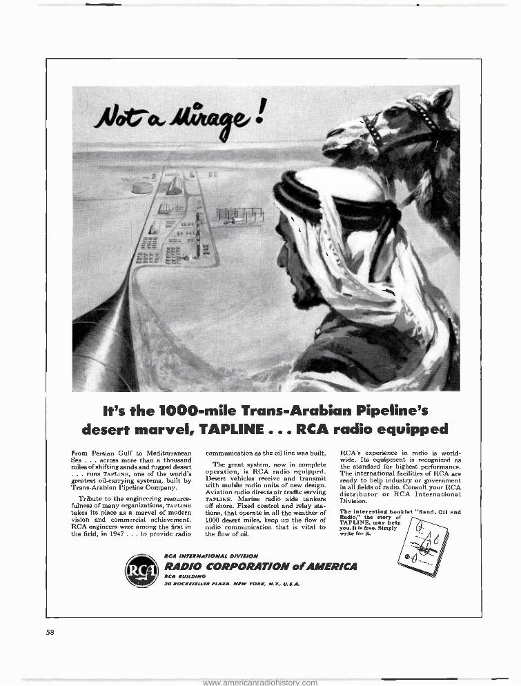
It's the 1000 -mile Trans -Arabian Pipeline's desert marvel, TAPLINE . .. RCA radio equipped
From Persian Gulf to Mediterranean Sea . across more than a thousand miles of shifting sands and rugged desert ... runs TAPLINE, one of the world's greatest oil- carrying systems, built by Trans -Arabian Pipeline Company.
Tribute to the engineering resource- fulness of many organizations, TAPLINE takes its place as a marvel of modern vision and commercial achievement. RCA engineers were among the first in the field, in 1947... to provide radio
communication as the oil line was built..
The great system, now in complete operation, is RCA radio equipped. Desert vehicles receive and transmit with mobile radio units of new design. Aviation radio directs air traffic serving TAPLINE. Marine radio aids tankers off shore. Fixed control and relay sta- tions, that operate in all the weather of 1000 desert miles, keep up the flow of radio communication that is vital to the flow of oil.
RCA INTERNATIONAL DIVISION
RCA's experience in radio is world- wide. Its equipment is recognized as the standard for highest performance. The international facilities of RCA are ready to help industry or government in all fields of radio. Consult your RCA distributor or RCA International Division. The interesting booklet "Sand, Oil and Radio," the story of TAPLINE, may help you. It is free. Simply write for it.
RADIO CORPORATION of AMERICA RCA BUILDING 30 ROCKEFELLER PLAZA, NEW YORK, N.Y., U.S.A.
5 Ú
www.americanradiohistory.com
Field Engineering Service
to Broadcasters...AM, FM, Tv
RCA Service Contltany engineers are
experienced in all the latest techniques and are equipped with the most modern specialized measuring equipment. The RCA Service Company has been work- ing hand in hand with the nation's broadcasters for over 25 years.
OUR SERVICE TO
BROADCASTERS . . . .
Installation supervision and measure- ments of transmitting, studio and accessory equipment . . . AM, FM or TV.
Instruction and training of station op- erating personnel.
Measurement and curves on FM and TV antennas and accessory equip- ment, including transmission lines, matching networks, diplexers.
Prompt help in emergencies. Technical advice, service, and assistance on spe- cial problems.
Performance measurements and ad ust- ments for station compliance with FCC regulations.
For further information call or write Communications Service Section, RCA Service Company, Inc., Camden, N. J.
(For service outside the I. S. A.. con- sult your Authorized RCA Distributor)
NOW -restore the original quality of your RCA mitres phones, transcription pick -ups and test and measuring equipment under the new Factory- Reconditioning Plan. For complete details, write: Return Apparatus Control, Building 8-2, Camden, N. J.
RCA Service Company, Inc. A Subsidiary of the Radio Corporation of America
CAMDEN, NEW JERSEY
low RCA 2 Ir/aY oio twerre-fri.0
. an illustrated fact -book about 2 -way radio in public -safety services. Tells "how -it- works" and " how-to - use-it" in easy, straightforward terms.
... shows how RCA 2 -way radio speeds law enforcement, fire -fighting operations. Describes municipal and state communication networks. Illus- trates use in forestry conservation, flood control, game -law enforcement.
In highway maintenance, it shows how RCA 2 -way radio can speed operations ... cut costs. There is even information about civil defense...
disaster relief ... school bus co-ordi- nation ... ambulance dispatching ... physicians and veterinarians.
Ir explains RCA's consultation service ... its maintenance plan ... tells how RCA helps plan the best 2 -way radio system for your needs... how to obtain frequency assignments ... FCC Construction Permits.
The "must" reference book for each and every man in public -safety services. For your copy, mail the cou- pon. an Canada, write: RCA Victor Limited, Montreal.) '/ ///
/
,....., ? iE:::w 'AZ .,... ...., ú üü
RCA ENGINEERING PRODUCTS Deot. 129 -1
Camden, New Jersey
Send me a free copy of "2 -way Radio for Public Safety."
Name
Firm
Address_
City
Title
Statt
RADIO CORPORATION of AMER /CA ï
59
www.americanradiohistory.com
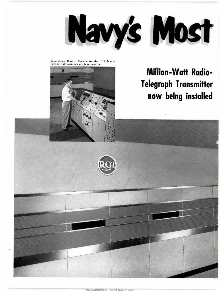
Supervisory Control Console for the U. S. Navy's million -watt radio -telegraph transmitter.
most Million -Watt Radio-
Telegraph Transmitter
now being installed
www.americanradiohistory.com
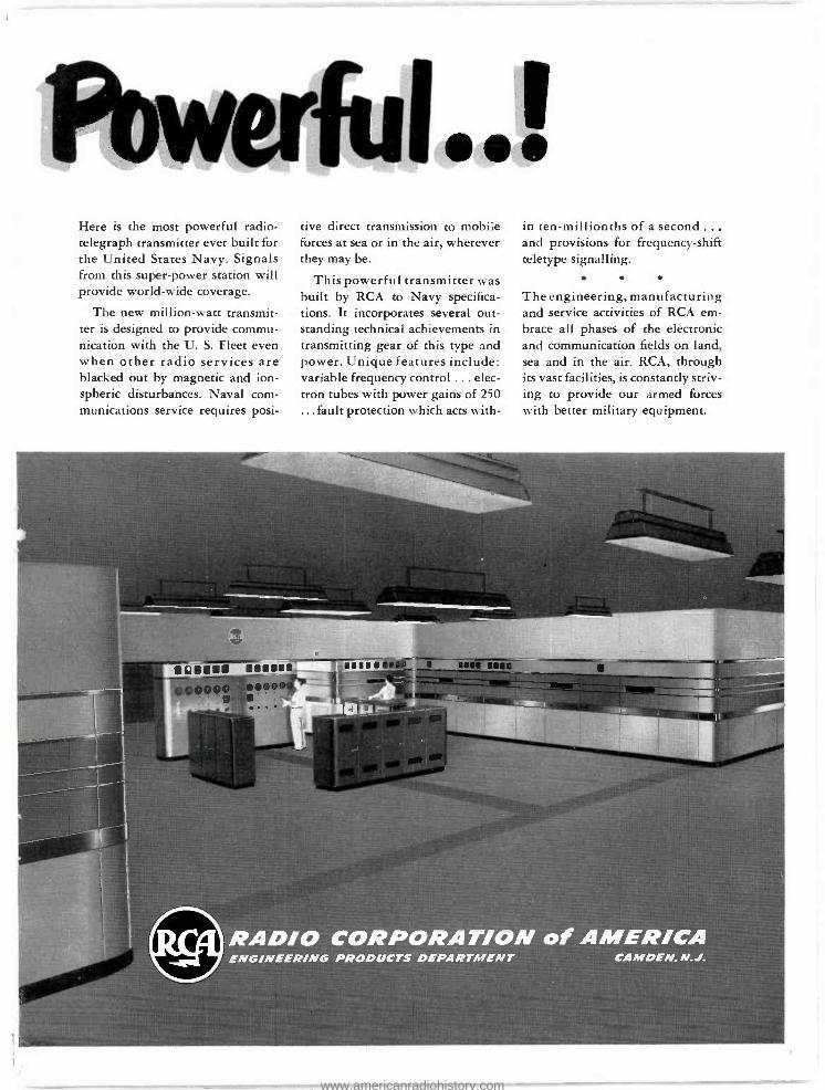
Powerful...! Here is the most powerful radio- telegraph transmitter ever built for the United States Navy. Signals from this super -power station will provide world -wide coverage.
The new million -watt transmit- ter is designed to provide commu- nication with the U. S. Fleet even when other radio services are blacked out by magnetic and ion - spheric disturbances. Naval com- munications service requires posi-
tive direct transmission to mobile forces at sea or in the air, wherever they may be.
This powerful transmitter was built by RCA to Navy specifica- tions. It incorporates several out- standing technical achievements in transmitting gear of this type and power. Unique features include: variable frequency control ... elec- tron tubes with power gains of 250 ...fault protection which acts with-
in ten -millionths of a second... and provisions for frequency -shift teletype signalling.
The engineering, manufacturing and service activities of RCA em- brace all phases of the electronic and communication fields on land, sea and in the air. RCA, through its vast facilities, is constantly striv- ing to provide our armed forces with better military equipment.
RADIO CORPORATION of AMER /CA ENGINEER /NG PRODUCTS DEPARTMENT CAMDEN, N.J.
www.americanradiohistory.com
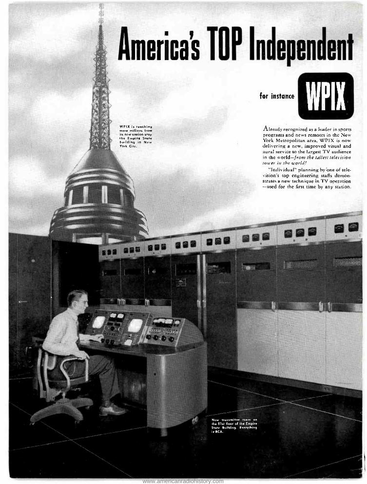
America's T 0 P Independent
WPIX is mashing more millions from its new station atop the Empire State Building in New York City.
sal ®se 0®® VII
for instance
WPIX Already recognized as a leader in sports programs and news remotes in the New York Metropolitan area, WPIX is now delivering a new, improved visual and aural service to the largest TV audience in the world -from the tallest television tower in the world!
"Individual" planning by 'one of tele- vision's top engineering staffs demon- strates a new technique in TV operation -used for the first time by any station.
,4040000000:01
' ®
New transmitter room on the 81st floor of the Empire State Building. Everything is RCA.
www.americanradiohistory.com
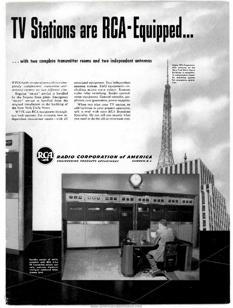
R TV Stations are
... with two
CA' Equipped a'.
complete transmitter rooms and two independent antennas
WPIX backs its operations with two com- pletely independent transmitter -and -
antenna systems on two different sites. Regular "on -air" service is handled
by the Empire State plant. Emergency "on -air" service is handled from the original installation in the building of the New York Daily News.
WPIX uses RCA equipment through- out both stations. For example, two in- dependent transmitter rooms -with all
i
associated equipment. Two independent antenna systems. Field equipment -in- cluding micro -wave relays. Remote video relay switching. Studio control - room equipment. Control consoles, am- plifiers, sync generators, power supplies.
When you plan your TV station, or add facilities to your present operation, talk it over with your RCA Broadcast Specialist. He can tell you exactly what you need to do the job at minimum cost.
i
6-bay RCA Superturn- stile antenna on the New York Daily News Building -a complete- ly independent stand- by radiating system for emergency opera- tion.
RADIO CORPORATION of AMERICA ENG /NEER /NG PRODUCTS DEPARTMENT CAMDEN. N.J.
SiV Ily O 1=' yy ® CHO ® ® w it ® 61 ®
Standby station of WPIX, complete with RCA 5 -kw TV transmitter, control con- sole, antenna diplexer, vestigial sideband filter, dummy load.
www.americanradiohistory.com
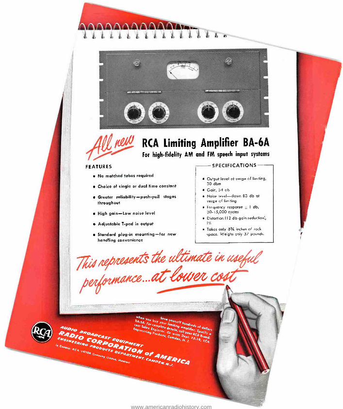
FEATURES
No matched tubes
RCA Limiting Amplifier BA -6A For high -fidelity AM and FM speech input systems
required
Choice of single or dual time constant
Greater reliability - push -pull stages
throughout
High gain -Low noise level
Adjustable T -pad in output
Standard plug -in mounting -for new handling convenience
SPECIFICATIONS
Output level at verge of limiting, 30 dbm
Gain, 54 db
Noise level -down 83 db at verge of limiting
Frequency response ± 1 db, 30-15,000 cycles
Distortion (I 2 db gain reduction), I%
Takes only 83/4 inches of rack space. Weighs only 37 pounds.
eiti#62 ffiejed
www.americanradiohistory.com
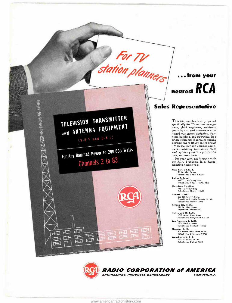
from your
nearest RCA
Sales Representative
This 64 -page book is prepared specifically for TV station manage- ment, chief engineers, architects, consultants, and attorneys con- nected with station designing, plan- ning, building, and operating. In a single reference it contains concise descriptions of RCA's entire line of TV transmitter and antenna equip- ment- including transmitter plans and layouts, general application data, and cost charts.
For your copy, get in touch with the RCA Broadcast Sales Repre- sentative nearest you:
New York 20, N. Y. 36 W. 49th Street Telephone: Circle 6 -4030
Dallas 1, Texas 1907 -11 McKinney Ave. Telephone: R -1371, 1372, 1373
Cleveland 15, Ohio 718 Keith Building Telephone: Cherry 1.3450
Atlanta 3, Ga. 522 -533 Forsyth Bldg. Forsyth and Luckie Streets, N. W. Telephone: Walnut 5946
Kansas City 8, Mo. 221 W. 18th Street Telephone: Victor 6410
Hollywood 28, Calif. 1560 North Vine Street Telephone: Hollywood 9-2154
San Francisco 3, Calif. 1355 Market Street Telephone: Hemlock 1 -8300
Chicago 11, III. 666 North Lake Shore Drive Telephone: Delaware 7 -0700
Washington 6, D. C. 1625 K Street, N. W. Telephone: District 1260
RADIO CORPORATION of AMERICA ENGINEERING PRODUCTS DEPARTMENT CAMDEN, N.J.
www.americanradiohistory.com
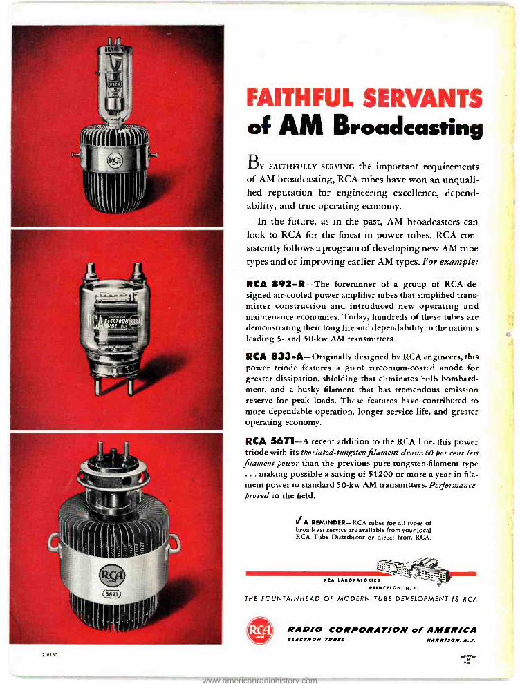
218180
FAITHFUL SERVANTS of AM Broadcasting
BY FAITHFULLY SERVING the important requirements of AM broadcasting, RCA tubes have won an unquali- fied reputation for engineering excellence, depend- ability, and true operating economy.
In the future, as in the past, AM broadcasters can look to RCA for the finest in power tubes. RCA con- sistently follows a program of developing new AM tube types and of improving earlier AM types. For example:
RCA 892 -R -The forerunner of a group of RCA -de- signed air -cooled power amplifier tubes that simplified trans- mitter construction and introduced new operating and maintenance economies. Today, hundreds of these tubes are demonstrating their long life and dependability in the nation's leading 5- and 50 -kw AM transmitters.
RCA 833 -A- Originally designed by RCA engineers, this power triode features a giant zirconium- coated anode for greater dissipation, shielding that eliminates bulb bombard- ment, and a husky filament that has tremendous emission reserve for peak loads. These features have contributed to more dependable operation, longer service life, and greater operating economy.
RCA 5671 -A recent addition to the RCA line, this power triode with its thoriated -tungsten filament draws 60 per cent less
filament power than the previous pure- tungsten -filament type ... making possible a saving of $1200 or more a year in fila- ment power in standard 50 -kw AM transmitters. Performance - proved in the field.
IA REMINDER -RCA tubes for all types of broadcast service are available from your local RCA Tube Distributor or direct from RCA.
RCA LABORATORIES
PRINCETON, N.J.
THE FOUNTAINHEAD OF MODERN TUBE DEVELOPMENT IS RCA
RADIO CORPORATION of AMERICA Vak ELECTRON THIES HARRISON. N. J.
www.americanradiohistory.com