broaching machinesmitpolytechnic.ac.in/...mechanical/.../unit3ommppt.pdf · broaching machines •...
TRANSCRIPT
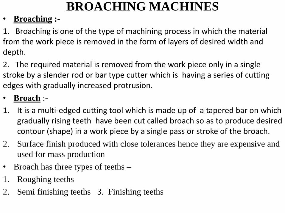
BROACHING MACHINES • Broaching :-
1. Broaching is one of the type of machining process in which the material from the work piece is removed in the form of layers of desired width and depth.
2. The required material is removed from the work piece only in a single stroke by a slender rod or bar type cutter which is having a series of cutting edges with gradually increased protrusion.
• Broach :-
1. It is a multi-edged cutting tool which is made up of a tapered bar on which gradually rising teeth have been cut called broach so as to produce desired contour (shape) in a work piece by a single pass or stroke of the broach.
2. Surface finish produced with close tolerances hence they are expensive and
used for mass production
• Broach has three types of teeths –
1. Roughing teeths
2. Semi finishing teeths 3. Finishing teeths
Continued..
Continued…
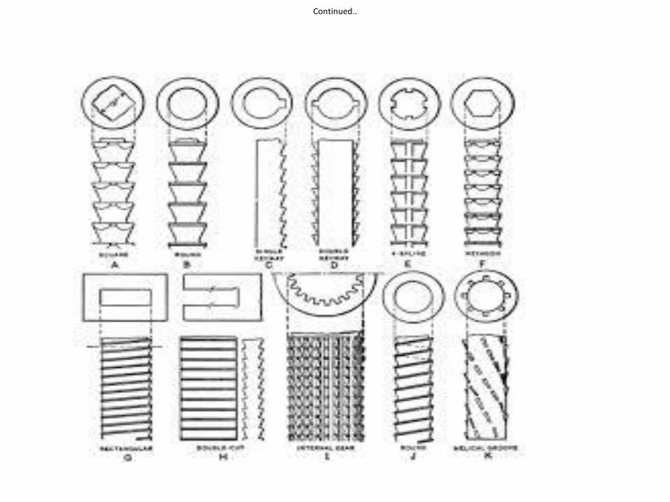
Types of broaches :-
• According to the type of operation :-
1. Internal
2. External
• According to the method of operation :-
1. Push type
2. Pull type
• According to the type of construction :-
1. Solid
2. Built up
3. Inserted tooth
• According to the Function / application :-
1. Surface broach
2. Key way broach
3. Spline broach
4. Round hole broach
BROACH ELEMENTS
Continued…
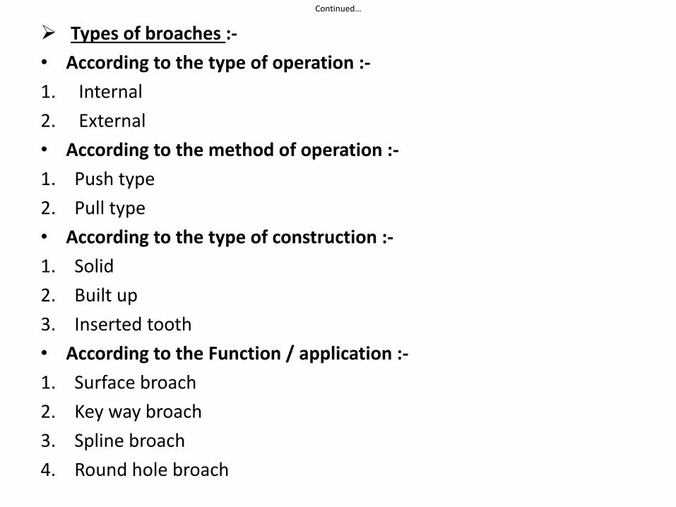
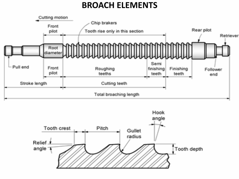
Broach Elements :-
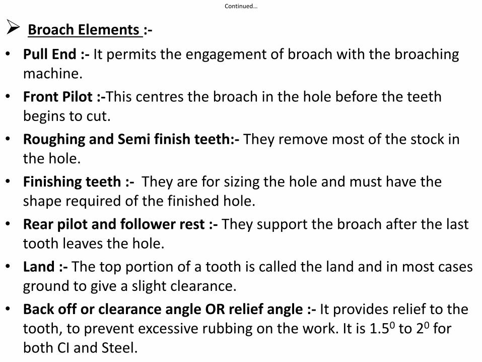
• Pull End :- It permits the engagement of broach with the broaching machine.
• Front Pilot :-This centres the broach in the hole before the teeth begins to cut.
• Roughing and Semi finish teeth:- They remove most of the stock in the hole.
• Finishing teeth :- They are for sizing the hole and must have the shape required of the finished hole.
• Rear pilot and follower rest :- They support the broach after the last tooth leaves the hole.
• Land :- The top portion of a tooth is called the land and in most cases ground to give a slight clearance.
• Back off or clearance angle OR relief angle :- It provides relief to the tooth, to prevent excessive rubbing on the work. It is 1.50 to 20 for both CI and Steel.
Continued…
• Rake or hook angle or face angle :- It is the angle of the cutting edge of a broach tooth. It is generally 12 to 150
• Pitch :- It is the linear distance from the cutting edge of one tooth to the corresponding edge of the next tooth.
• Broach material :- Most broaches are made up of 18-4-1
tungsten chromium vanadium steel ground after hardening.
continued,…
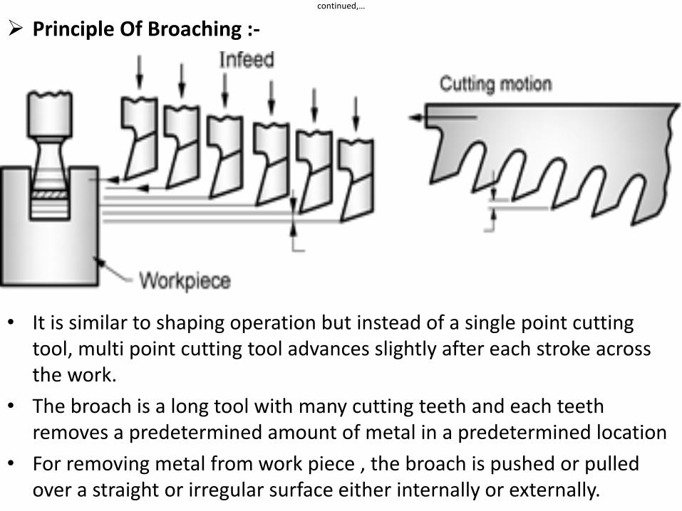
Principle Of Broaching :-
• It is similar to shaping operation but instead of a single point cutting tool, multi point cutting tool advances slightly after each stroke across the work.
• The broach is a long tool with many cutting teeth and each teeth removes a predetermined amount of metal in a predetermined location
• For removing metal from work piece , the broach is pushed or pulled over a straight or irregular surface either internally or externally.
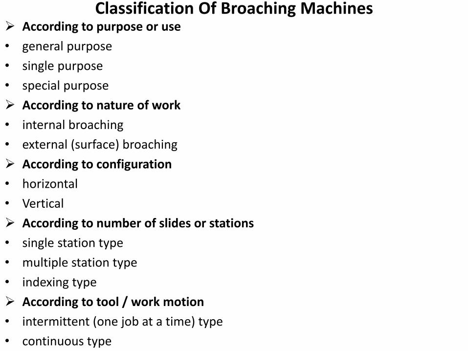
Classification Of Broaching Machines According to purpose or use
• general purpose
• single purpose
• special purpose
According to nature of work
• internal broaching
• external (surface) broaching
According to configuration
• horizontal
• Vertical
According to number of slides or stations
• single station type
• multiple station type
• indexing type
According to tool / work motion
• intermittent (one job at a time) type
• continuous type
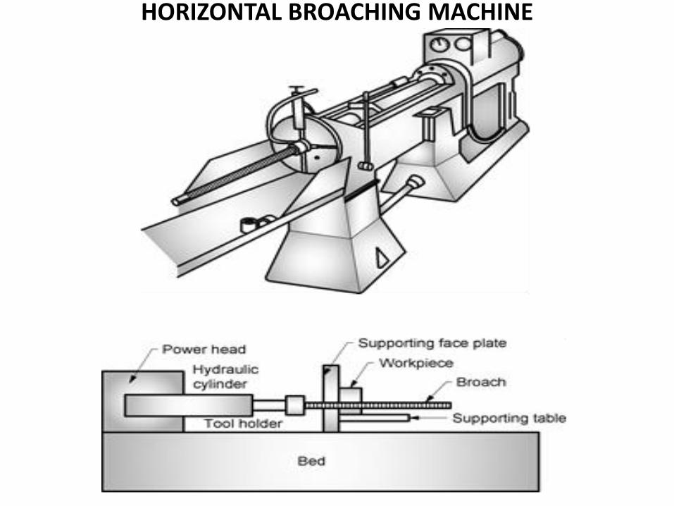
HORIZONTAL BROACHING MACHINE
HORIZONTAL BROACHING MACHINE Introduction :-
• They are suitable for extremely long strokes ( More than 2000mm)
• They may be used for either internal or external broaching.
• Further they are classified as pull or push machines depending upon the direction of force applied to the broach.
• This machine is used for broaching of key ways, splines, slots, round holes and other internal shapes.
Construction :- Consist of following parts –
1. Base/ Bed
2. Broach
3. Drive mechanism
4. Work piece fixture
5. Pulling head ( end )
Continued…
Advantages Of Broaching Machines :-
1. Suitable for mass production
2. No special skill is required
3. High accuracy and good surface finish
4. Roughing and finishing cuts are possible in single pass
5. Internal as well as external surfaces can be machined
6. Variety of shapes can be reproduced
7. Easy to apply cutting fluid due to movement of broach.
Disadvantages Of Broaching Machines :-
1. High tool cost
2. Very large work pieces can not be broached.
3. Surfaces to be broached can not have an obstruction.
4. Can not be used for the removal of a large amount of stock
5. The parts to be broached must be strong enough to withstand high cutting forces
Continued…
• Applications Of Broaching Machines :-
1. Machining of internal and external surfaces like key way, splined shaft, surface broaching.
2. Automobile components like crank cases, cylinder heads, connecting rods, caps, power steering pistons, steering worms are machined by broaching .
3. Used to produce wide range of components in rifle and gun manufacture
4. Manufacturing of parts for aircrafts engines and structures
5. Special gears, bushing and sleeves, rotors, turbine blades, compressor wheels, chain sprocket teeths, propeller hubs etc
CAPSTAN AND TURRET LATHE Introduction :-
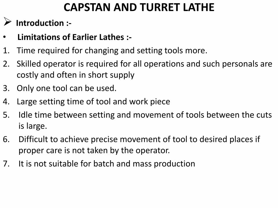
• Limitations of Earlier Lathes :-
1. Time required for changing and setting tools more.
2. Skilled operator is required for all operations and such personals are costly and often in short supply
3. Only one tool can be used.
4. Large setting time of tool and work piece
5. Idle time between setting and movement of tools between the cuts is large.
6. Difficult to achieve precise movement of tool to desired places if proper care is not taken by the operator.
7. It is not suitable for batch and mass production
Continued…
• All these limitations are overcome by the development of modified lathes like capstan and turret lathes, semi-automatic and automatic machines.
• The improvements are basically in the following areas –
1. multiple tool availability
2. Work holding methods
3. Automatic feeding of tools
4. Automatic stopping of tools at precise locations
5. Automatic control of the proper sequence of operations.
Main Features Of Capstan And Turret Lathe • As the headstock has more and heavier range of speeds, so the
higher production rate is possible
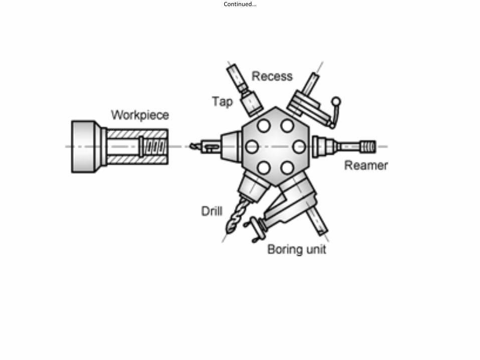
• It has indexable tool post and can mount four tools of which any one tools can be brought into the cutting position.
• It is having no tailstock. The tailstock is replaced by a tool turret having six tool positions.
• The feed of each tool can be adjusted by means of feed stops.
• Can be possible to mount two or more tools on a single tool face can cut simultaneously.
• These lathes are suitable for production operations in which better repeatability is required.
• Semi-skilled operators are sufficient to operate the machine
Continued…
Continued…
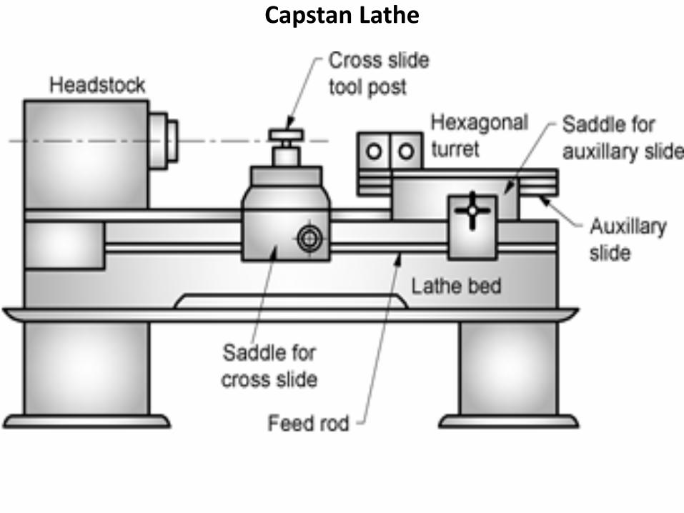
Capstan Lathe
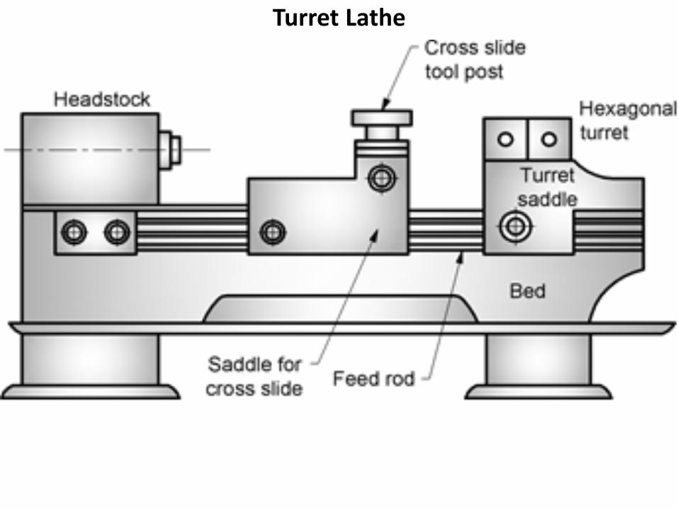
Turret Lathe
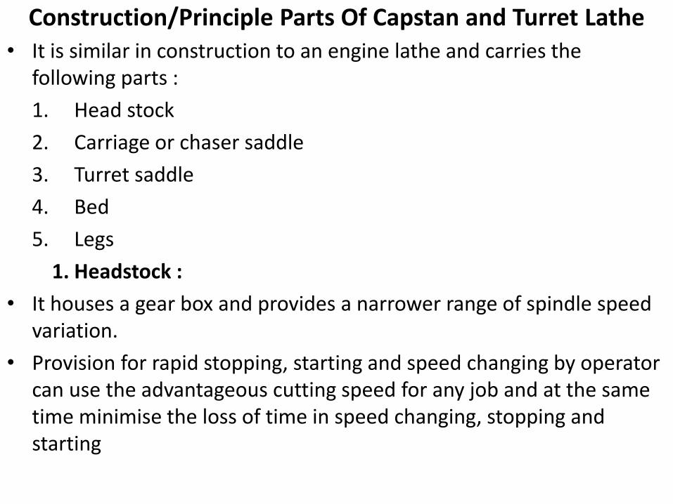
Construction/Principle Parts Of Capstan and Turret Lathe • It is similar in construction to an engine lathe and carries the
following parts :
1. Head stock
2. Carriage or chaser saddle
3. Turret saddle
4. Bed
5. Legs
1. Headstock :
• It houses a gear box and provides a narrower range of spindle speed variation.
• Provision for rapid stopping, starting and speed changing by operator can use the advantageous cutting speed for any job and at the same time minimise the loss of time in speed changing, stopping and starting
Continued…
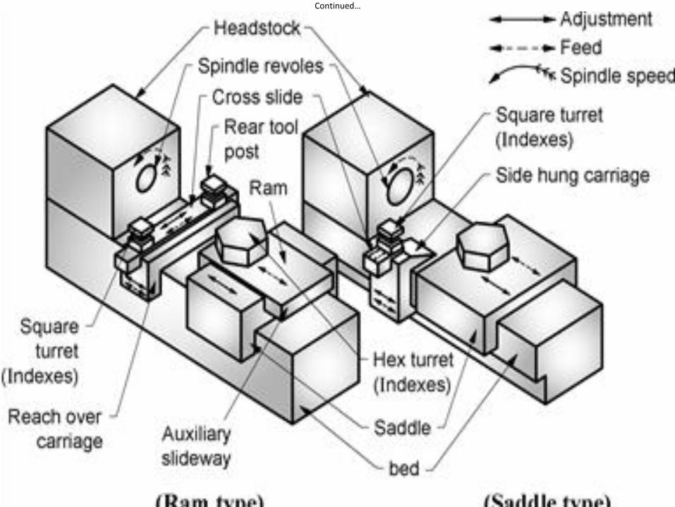
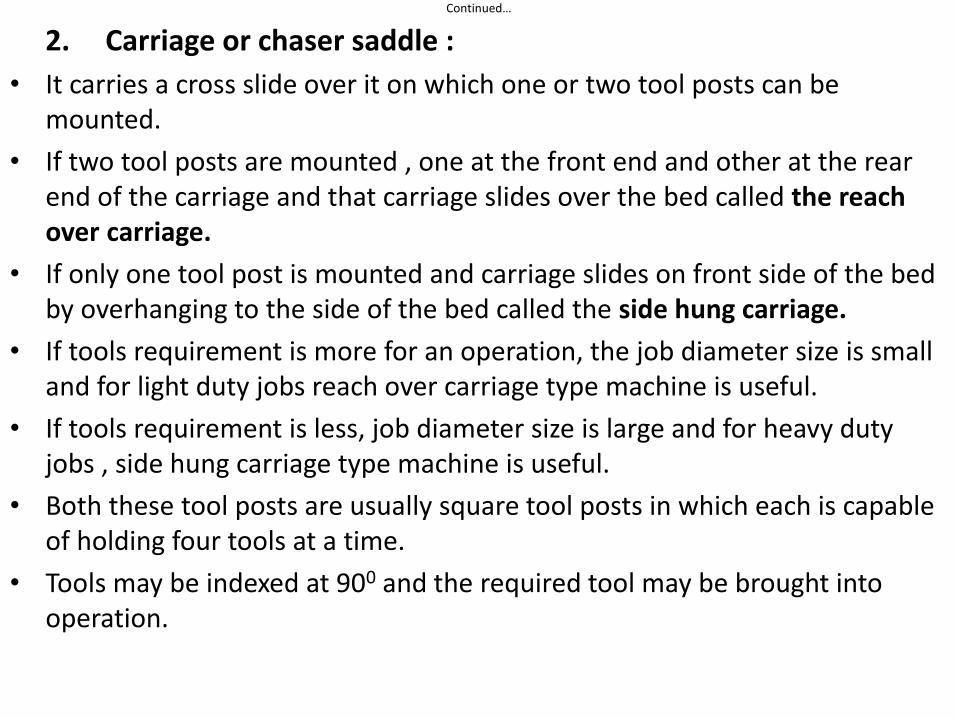
2. Carriage or chaser saddle :
• It carries a cross slide over it on which one or two tool posts can be mounted.
• If two tool posts are mounted , one at the front end and other at the rear end of the carriage and that carriage slides over the bed called the reach over carriage.
• If only one tool post is mounted and carriage slides on front side of the bed by overhanging to the side of the bed called the side hung carriage.
• If tools requirement is more for an operation, the job diameter size is small and for light duty jobs reach over carriage type machine is useful.
• If tools requirement is less, job diameter size is large and for heavy duty jobs , side hung carriage type machine is useful.
• Both these tool posts are usually square tool posts in which each is capable of holding four tools at a time.
• Tools may be indexed at 900 and the required tool may be brought into operation.
Continued…
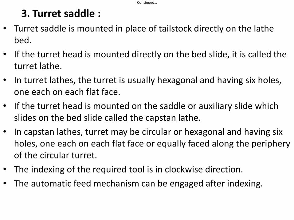
3. Turret saddle :
• Turret saddle is mounted in place of tailstock directly on the lathe bed.
• If the turret head is mounted directly on the bed slide, it is called the turret lathe.
• In turret lathes, the turret is usually hexagonal and having six holes, one each on each flat face.
• If the turret head is mounted on the saddle or auxiliary slide which slides on the bed slide called the capstan lathe.
• In capstan lathes, turret may be circular or hexagonal and having six holes, one each on each flat face or equally faced along the periphery of the circular turret.
• The indexing of the required tool is in clockwise direction.
• The automatic feed mechanism can be engaged after indexing.
Continued…
4. Bed :
• It is a box shaped grey C.I. iron casting.
• So many stiffening ribs are provided internally to the bed for strengthening it.
• The turret saddle and cross slide travels on the guide-ways on the top of the bed.
5. Legs :
• There are two legs, one each below both ends of the bed
• The legs are hollow castings which withstands the entire load of the bed, of the sliding and stationary parts mounted over the bed and also of tooling and work holding devices or mechanism and a reach over carriage which has transverse movement.
AUTOMATS/AUTOMATIC MACHINES Introduction :-
• When work piece handling and metal cutting operations are performed without human assistance, it is known as automatic machines.
• Used for in increasing the production rate
• Initial setting is require to do very carefully because these machines are used for repetative work to produce duplicate parts without the operator.
• Feeding of the stock ( work piece) , clamping, machining and even inspection of the work piece are carried out automatically.
• This machine is provided with feed mechanism to feed the work pieces for machining, indexing mechanism for selecting the required tool as per the type of machining requirement and cutting off mechanism or devices to cut the machined work pieces in required sizes.
• The role of operator is only to set the machine carefully and load the raw material and operations including unloading, machining, tool indexing are done automatically.
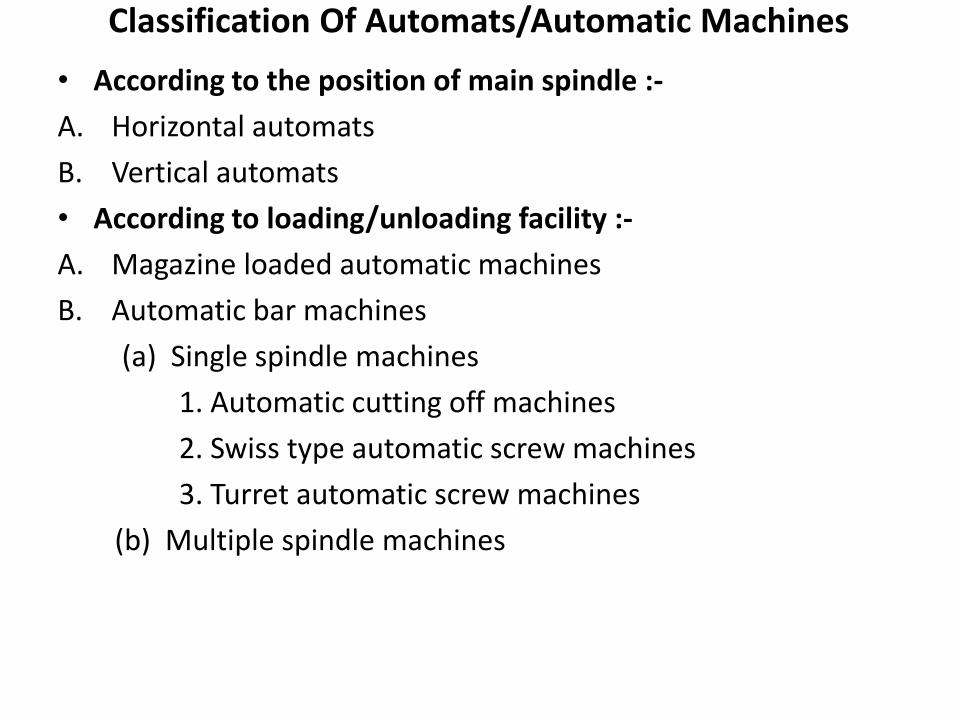
Classification Of Automats/Automatic Machines
• According to the position of main spindle :-
A. Horizontal automats
B. Vertical automats
• According to loading/unloading facility :-
A. Magazine loaded automatic machines
B. Automatic bar machines
(a) Single spindle machines
1. Automatic cutting off machines
2. Swiss type automatic screw machines
3. Turret automatic screw machines
(b) Multiple spindle machines
Continued…
Horizontal Automats :-
1. Spindle is in horizontal direction
2. Suitable for machining jobs of small diameters
3. Require more linear space
Vertical Automats :-
1. Spindle is in vertical direction
2. Heavier, more rigid and strong construction.
3. Can machine jobs of larger diameter but shorter in length
4. Require less space
Continued…
Magazine Loaded Automatic Machines :-
1. Used to machine the work pieces in the form of blanks.
2. Magazine is a circular shaped work table having facility to load the number of work pieces or blanks .
3. Magazine has a locating facility for each of the work pieces or blanks.
Automatic Bar Machines :- The work pieces are machined from the bar or pipe
Single Spindle Machines :-
• Automatic cutting off machines
• Swiss type automatic screw machines
• Turret type automatic screw machines
Multiple Spindle Machines
Single Spindle Machines
These machines are the logical development over capstan and
turret lathes.
Automatic cutting off machines :-
1. It is a single spindle automatic machine.
2. It is used for producing short work pieces of simple form with the help of form tools mounted on cross slide.
3. It has front and rear cross slide provided on the bed. Tools are held in the front as well as rear cross slide which are used for machining the bar to the required geometrical form.
4. Work piece is held in the chuck and rotates in horizontal spindle
5. Cross slide movement is actuated by means of cams on cam shaft and lever system
6. The required length of bar stock is fed automatically up to the bar stop by means of cam mechanism.

Continued…
Swiss Type Automatic screw Machine
Continued…
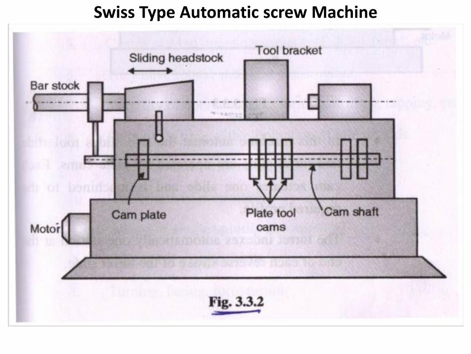
Swiss type automatic screw machines :-
1. It is used for manufacturing of small precise components.
2. Suitable for long cylindrical work pieces and where accuracy, finish and concentricity is important
3. It is also called as sliding head type in which the bar stock is fed through a sliding headstock and held by a collet chuck.
4. The tool bracket supporting five tool slides and each slide is operated by a separate cam which is mounted in the centre.
5. Cams provided on the front cam shaft are used to control the tool slides and headstock movements.
6. The headstock moves the rotating bar near the tools fitted longitudinally on tool bracket. The bar may be rotating at constant speed for turning and with slow speed for threading.
Turret Automatic Screw Machine
Continued…
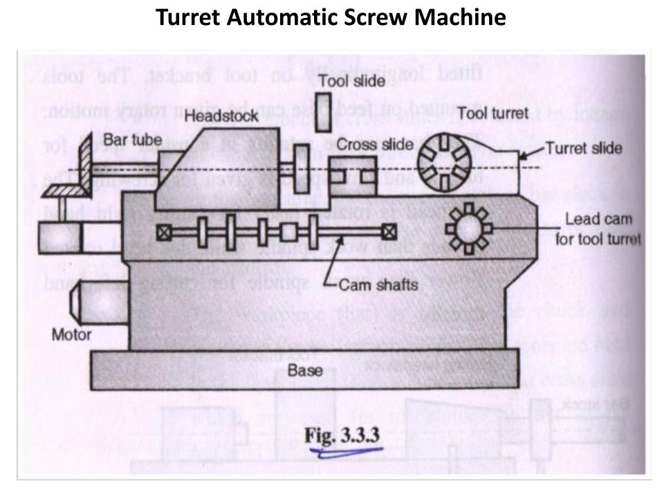
Turret Automatic Screw Machines :-
1. This is the development of capstan lathe.
2. The turret is mounted at tailstock which can hold up to six tools and other tools on front and rear tool slides. All these tools are automatically fed at the correct time during the cycle of cams.
3. Each cam actuates the tool slide and turret slide.
4. The indexing of the turret is automatic.
5. Cam shaft located in the front of the machine is driven through the cycle time change gears depending on the component to be produced.
6. The dog clutches are used to open the collet chuck and advance the bar, change the spindle speed and index the turret.
7. One revolution of the cam shaft produces one component .
8. The threads are produced with the help of thread dies or chasers at the cross slide
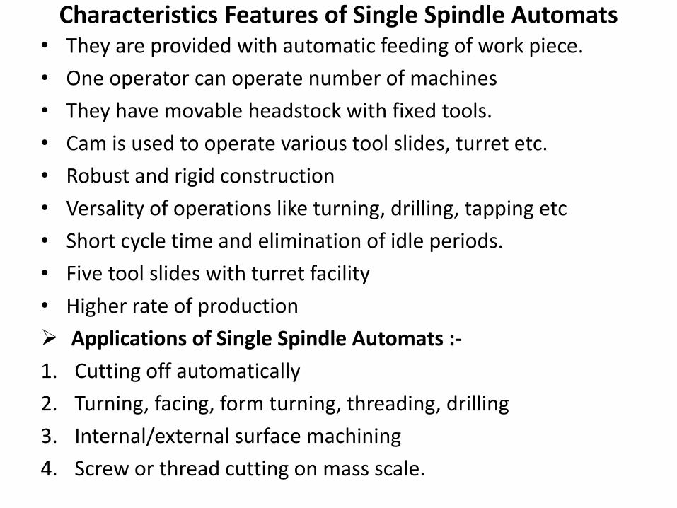
Characteristics Features of Single Spindle Automats • They are provided with automatic feeding of work piece.
• One operator can operate number of machines
• They have movable headstock with fixed tools.
• Cam is used to operate various tool slides, turret etc.
• Robust and rigid construction
• Versality of operations like turning, drilling, tapping etc
• Short cycle time and elimination of idle periods.
• Five tool slides with turret facility
• Higher rate of production
Applications of Single Spindle Automats :-
1. Cutting off automatically
2. Turning, facing, form turning, threading, drilling
3. Internal/external surface machining
4. Screw or thread cutting on mass scale.
Multiple Spindle Machines • It is the development over single spindle automats.
• In these machines, number of bars of stock or components are machined simultaneously thus increasing the production output.
• The number of spindles may be four, five, six or eight, but four spindle type is the most commonly used.
• The spindles carrying the bar stock are indexed in order against each tool station.
• A driving gear is located at the centre of carrier which holds all spindles and drives all the spindles
• The finished bar is to be cut off at one position and fed forward up to the stop to get ready for the next operation.
• The accuracy of multi spindle automats is lesser than single spindle automats.
PLANER Introduction :-
• This machine is used to produce plane and flat surfaces.
• The shaper machine is not suitable for producing flat surfaces on very large parts because of limitations of stroke and overhang of the ram. This limitation is solved by planner machine.
• This machine is useful to produce horizontal, vertical or inclined flat surfaces on the work pieces which are too large to be mounted on shaper machine.
• This machine is very large and massive compared to shaper machine.
Continued…
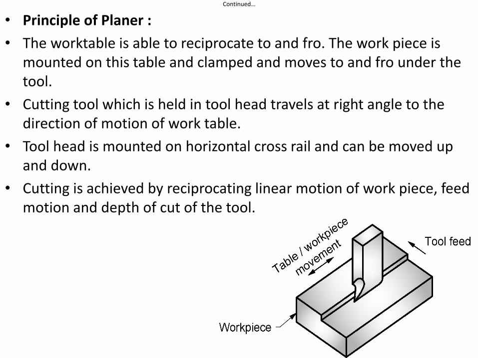
• Principle of Planer :
• The worktable is able to reciprocate to and fro. The work piece is mounted on this table and clamped and moves to and fro under the tool.
• Cutting tool which is held in tool head travels at right angle to the direction of motion of work table.
• Tool head is mounted on horizontal cross rail and can be moved up and down.
• Cutting is achieved by reciprocating linear motion of work piece, feed motion and depth of cut of the tool.
Continued…
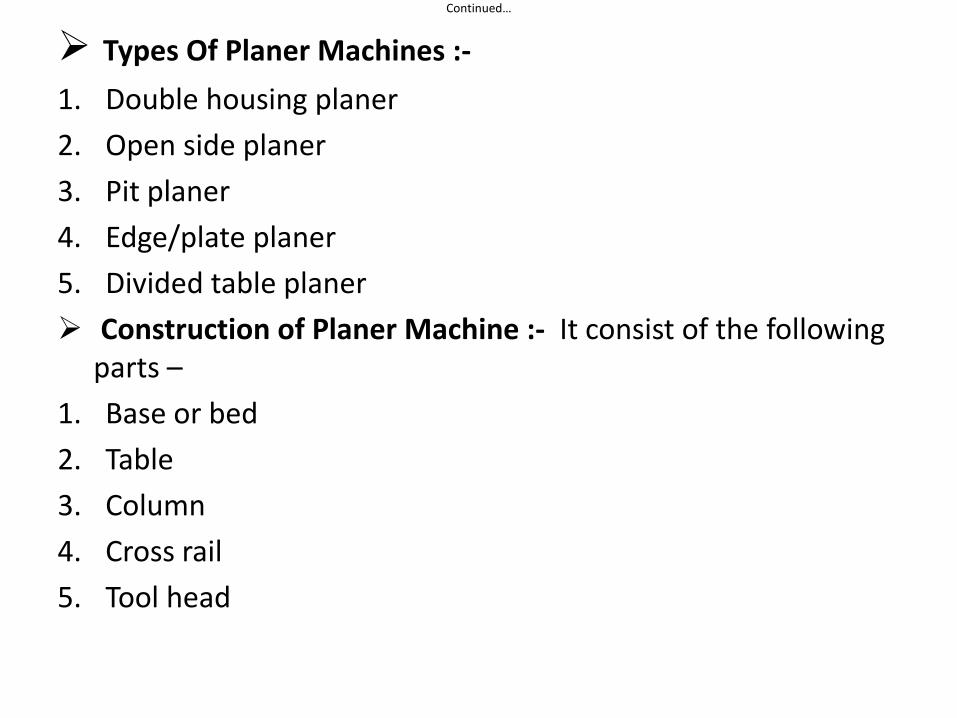
Types Of Planer Machines :-
1. Double housing planer
2. Open side planer
3. Pit planer
4. Edge/plate planer
5. Divided table planer
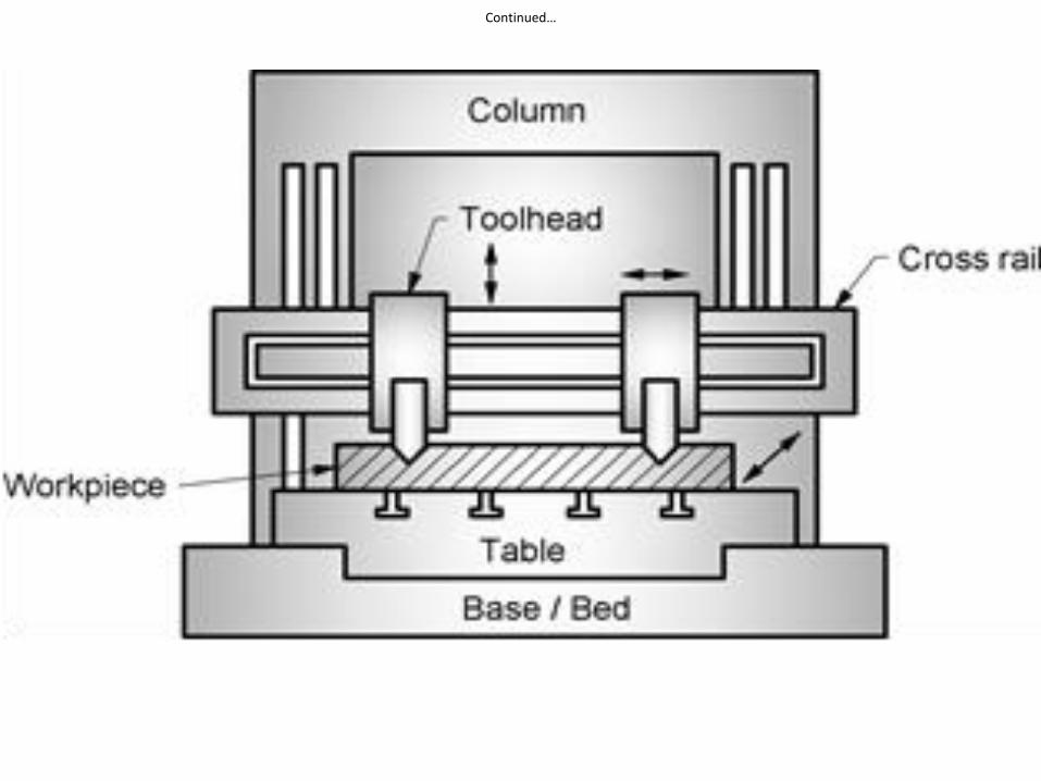
Construction of Planer Machine :- It consist of the following parts –
1. Base or bed
2. Table
3. Column
4. Cross rail
5. Tool head
Continued…
Continued…
• Base or Bed :-
1. it is a large casting also acts as base or foundation of machine.
2. It is made up of C.I.
3. Slides are provided in the bed on which the worktable is mounted and slides over it.
• Table :-
1. It is a large casting provided with T-slots to mount work pieces of different sizes with suitable clamping arrangement.
2. It is hydraulic driven with rack and pinion arrangement.
• Column :-
1. Vertical columns are provided on both the sides of the bed to mount the cross rail with tool head horizontally..
2. These columns are having the guide ways for cross rail to slide up and down.
Continued….
• Cross rail :-
1. It is mounted horizontally on two columns.
2. It can be moved up and down on the guide ways of columns
3. Provided for mounting the tool head.
4. Guide ways are provided in it for tool head movement over the cross rail.
• Tool head :-
1. It is used to hold the planer tool.
2. They are provided on cross rail for machining horizontal flat surface.
3. They can also be mounted on both columns for vertical flat machining of the work piece surface.
Continued…
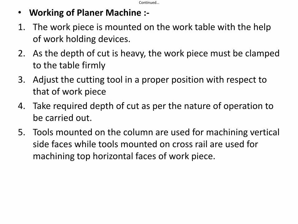
• Working of Planer Machine :-
1. The work piece is mounted on the work table with the help of work holding devices.
2. As the depth of cut is heavy, the work piece must be clamped to the table firmly
3. Adjust the cutting tool in a proper position with respect to that of work piece
4. Take required depth of cut as per the nature of operation to be carried out.
5. Tools mounted on the column are used for machining vertical side faces while tools mounted on cross rail are used for machining top horizontal faces of work piece.
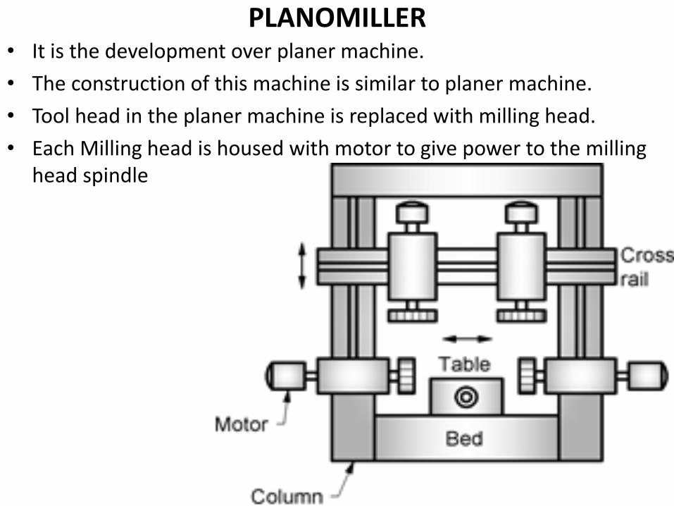
PLANOMILLER • It is the development over planer machine.
• The construction of this machine is similar to planer machine.
• Tool head in the planer machine is replaced with milling head.
• Each Milling head is housed with motor to give power to the milling head spindle
Continued…
Construction :- It is similar to the planer machine. It consist of following parts –
1. Bed :- It is the base of the machine
2. Table :- It is mounted on the bed. It has longitudinal movement only.
3. Column :- Two vertical columns, one on each side of the bed are mounted on the bed.
4. Cross rail :- It is fitted on the column. It may be lowered or raised to suit the height of the work piece.
5. Milling Head :- Two vertical milling heads are fitted on the cross rail which can move towards each other. Two horizontal milling heads are mounted on the column which can move vertical over it
6. Milling Cutter :- Each milling head carries one cutter
Continued…
• Working :- The work piece can be machined in four different ways according to the requirement
1. By moving the table only and cutter rotates in it’s position
2. By keeping the table stationary and feeding the cutters
3. By moving the table and cutters simultaneously
4. By keeping the table stationary, moving the cross rail downwards and the side cutter up and down.
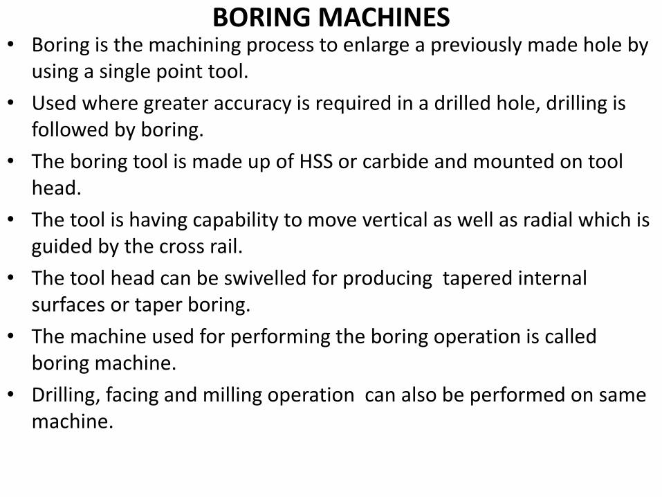
BORING MACHINES • Boring is the machining process to enlarge a previously made hole by
using a single point tool.
• Used where greater accuracy is required in a drilled hole, drilling is followed by boring.
• The boring tool is made up of HSS or carbide and mounted on tool head.
• The tool is having capability to move vertical as well as radial which is guided by the cross rail.
• The tool head can be swivelled for producing tapered internal surfaces or taper boring.
• The machine used for performing the boring operation is called boring machine.
• Drilling, facing and milling operation can also be performed on same machine.
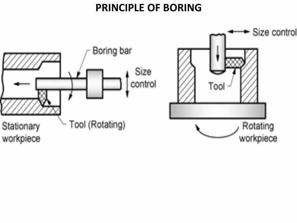
PRINCIPLE OF BORING
Continued…
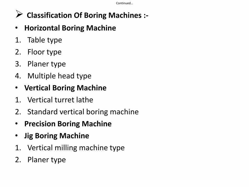
Classification Of Boring Machines :-
• Horizontal Boring Machine
1. Table type
2. Floor type
3. Planer type
4. Multiple head type
• Vertical Boring Machine
1. Vertical turret lathe
2. Standard vertical boring machine
• Precision Boring Machine
• Jig Boring Machine
1. Vertical milling machine type
2. Planer type
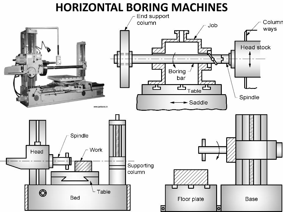
HORIZONTAL BORING MACHINES
-
Continued…
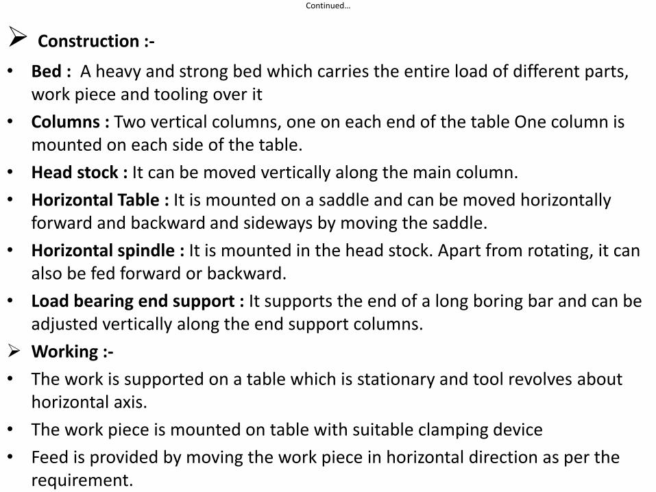
Construction :-
• Bed : A heavy and strong bed which carries the entire load of different parts, work piece and tooling over it
• Columns : Two vertical columns, one on each end of the table One column is mounted on each side of the table.
• Head stock : It can be moved vertically along the main column.
• Horizontal Table : It is mounted on a saddle and can be moved horizontally forward and backward and sideways by moving the saddle.
• Horizontal spindle : It is mounted in the head stock. Apart from rotating, it can also be fed forward or backward.
• Load bearing end support : It supports the end of a long boring bar and can be adjusted vertically along the end support columns.
Working :-
• The work is supported on a table which is stationary and tool revolves about horizontal axis.
• The work piece is mounted on table with suitable clamping device
• Feed is provided by moving the work piece in horizontal direction as per the requirement.
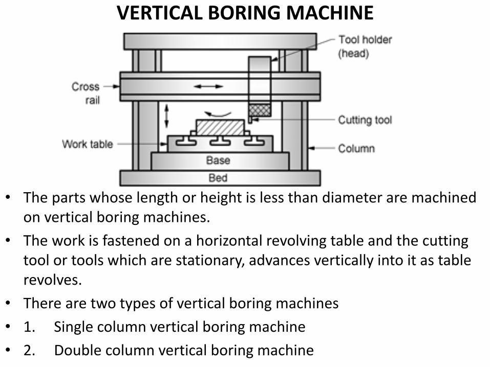
VERTICAL BORING MACHINE
• The parts whose length or height is less than diameter are machined on vertical boring machines.
• The work is fastened on a horizontal revolving table and the cutting tool or tools which are stationary, advances vertically into it as table revolves.
• There are two types of vertical boring machines
• 1. Single column vertical boring machine
• 2. Double column vertical boring machine
Continued…
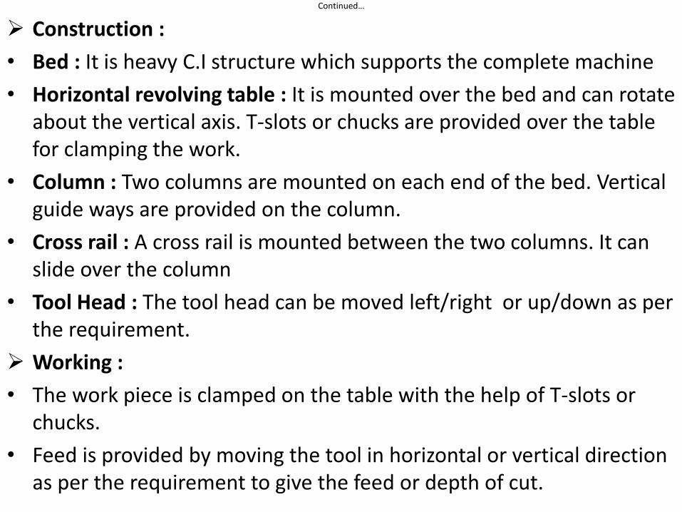
Construction :
• Bed : It is heavy C.I structure which supports the complete machine
• Horizontal revolving table : It is mounted over the bed and can rotate about the vertical axis. T-slots or chucks are provided over the table for clamping the work.
• Column : Two columns are mounted on each end of the bed. Vertical guide ways are provided on the column.
• Cross rail : A cross rail is mounted between the two columns. It can slide over the column
• Tool Head : The tool head can be moved left/right or up/down as per the requirement.
Working :
• The work piece is clamped on the table with the help of T-slots or chucks.
• Feed is provided by moving the tool in horizontal or vertical direction as per the requirement to give the feed or depth of cut.
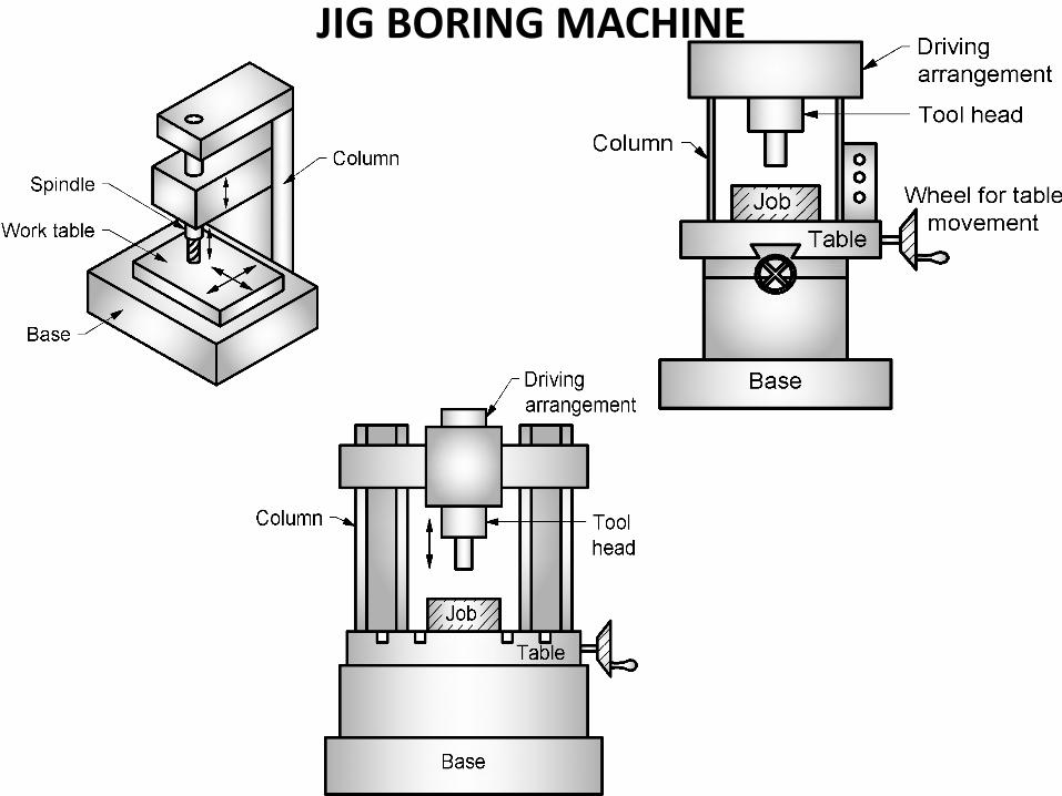
JIG BORING MACHINE
Continued…
• It is a vertical type boring machine and is very precise machine.
• Used for locating and boring holes in jigs and fixtures, dies , gauges and other precision parts.
• Constructed very precisely and is provided with accurate measuring devices for controlling table movements.
• These machines are possible to operate by numerical control.
• The machining accuracy is in the range of 0.0025 mm
• Highest accuracy achieved because of rigidity of machine, low thermal expansion of the parts of machine.
• The spindle and other parts of the machine are extremely rigid to resist deflection and vibration is minimum, type of bearings of the spindle used and very low coefficient of expansion of the material of spindle headstock.
• To prevent the influence of ambient temperature changes on machining, jig boring machines should be installed in special environmental enclosure with temperature maintained at 20 C.
• Types
• 1. Single column jig boring machine
• 2. Double column jig boring machine
BORING TOOLS Introduction :- It is a cutting tool which can be held in a boring bar or
boring head for carrying out necessary operations by a boring machine. The rotating tool or cutter is fed through hole in the job.
Types Of Boring Tools :-
1. Light boring tool
2. Forged boring tool
3. Boring bar
4. Double ended boring tool
5. Multiple edges boring tool
6. Counter boring tool
Continued…
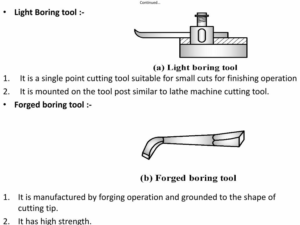
• Light Boring tool :-
1. It is a single point cutting tool suitable for small cuts for finishing operation
2. It is mounted on the tool post similar to lathe machine cutting tool.
• Forged boring tool :-
1. It is manufactured by forging operation and grounded to the shape of cutting tip.
2. It has high strength.
Continued…
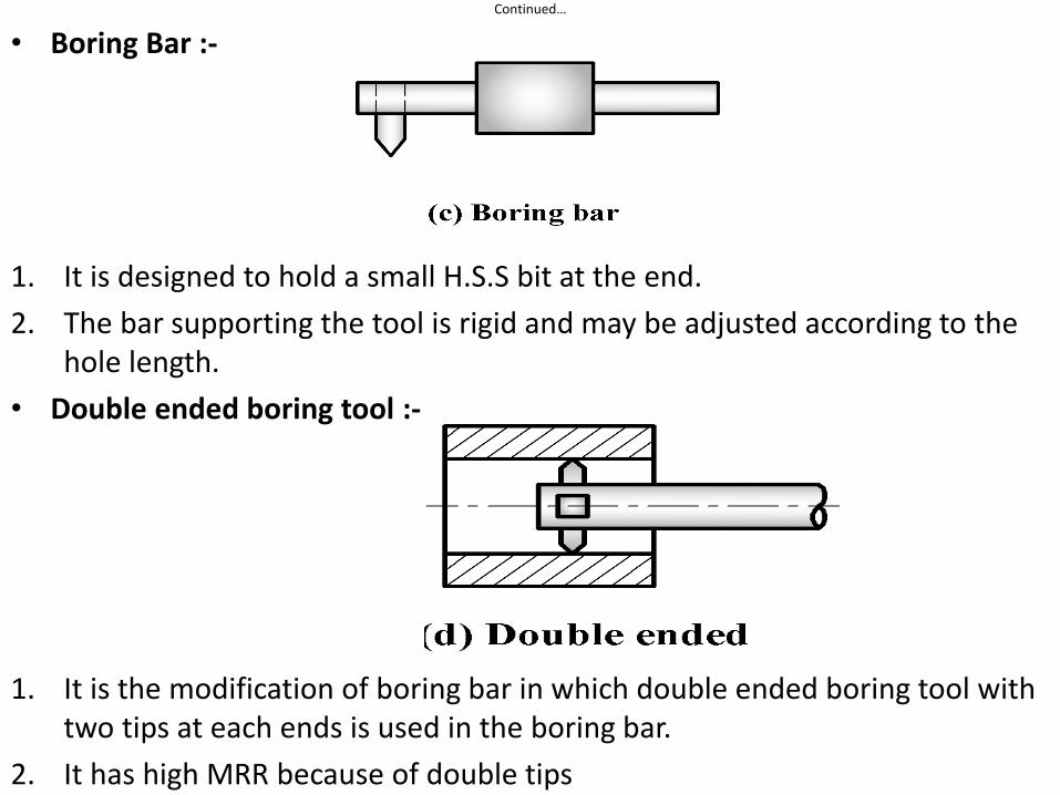
• Boring Bar :-
1. It is designed to hold a small H.S.S bit at the end.
2. The bar supporting the tool is rigid and may be adjusted according to the hole length.
• Double ended boring tool :-
1. It is the modification of boring bar in which double ended boring tool with two tips at each ends is used in the boring bar.
2. It has high MRR because of double tips
Continued…
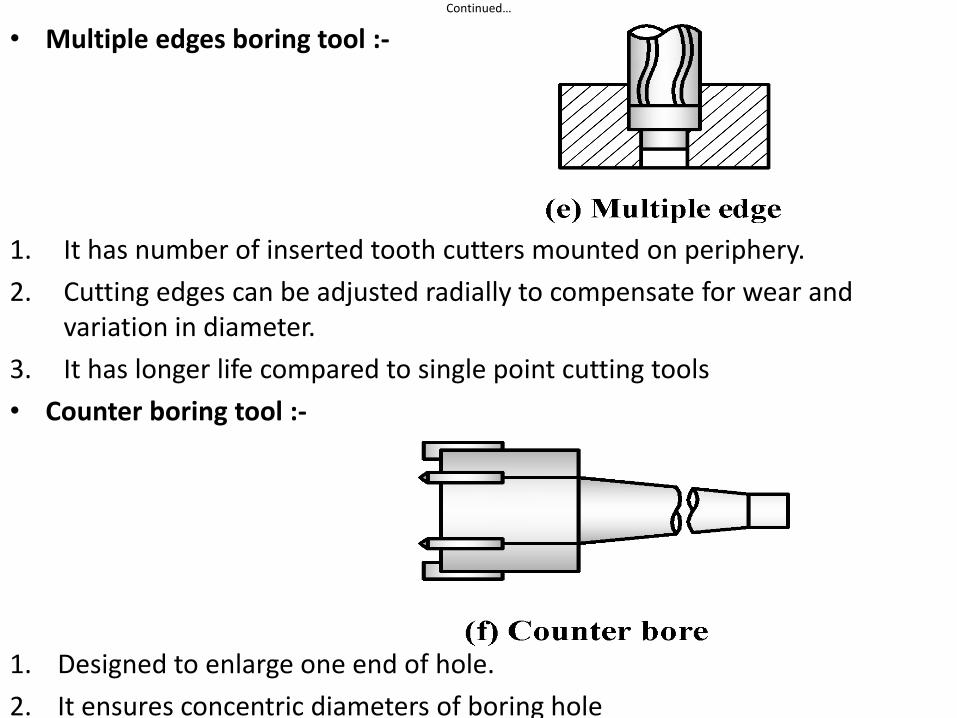
• Multiple edges boring tool :-
1. It has number of inserted tooth cutters mounted on periphery.
2. Cutting edges can be adjusted radially to compensate for wear and variation in diameter.
3. It has longer life compared to single point cutting tools
• Counter boring tool :-
1. Designed to enlarge one end of hole.
2. It ensures concentric diameters of boring hole
Continued…
HORIZONTAL BORING MACHINES OPERATIONS :-
• Drilling
• Boring operation
• Facing operation
• Threading / Tapping
• Counter boring
• Countersinking
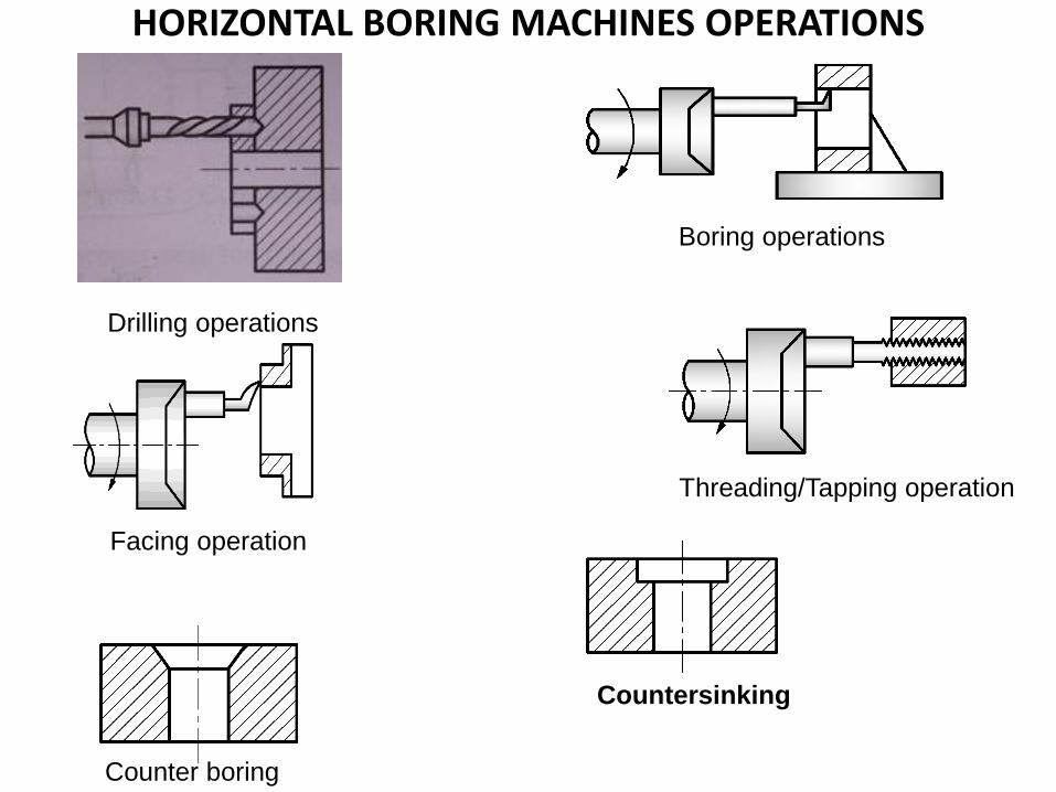
HORIZONTAL BORING MACHINES OPERATIONS
Boring operations
Facing operation
Threading/Tapping operation
Counter boring
Countersinking
Drilling operations

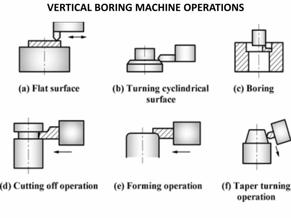
VERTICAL BORING MACHINE OPERATIONS
• Turning – flat, cylindrical, conical turning
• Boring
• Forming
• Cutting off / necking operation
VERTICAL BORING MACHINE OPERATIONS