british columbia hydro and power …€¦ · british columbia hydro and power authority hat creek...
TRANSCRIPT
~~ ~"
BRITISH COLUMBIA HYDRO AND POWER AUTHORITY
HAT CREEK PROJECT
Toby, Russell, Buckwell and Partners Architects - Bat Creek Project - Detailed Environmental Studies - Aesthetic Considerations - Ju:Ly 1978
ENVIRONMENTAL IMPACT STATEMENT REFERENCE NUMBER: 22
B R I T I S H C a L U M B l A HYDRO AND P O W E R A U T H O R I T Y
DETAILED ENVIRONMENTAL STUIIIIES 1
E4 AESTHETIC
CONSIDERATIONS
TOBY R U S S E L L B U C K W E L L IS P A R T N E R S A R C H I T E C T S CONSULTANTS
JJSTICE 8 WEBB LANDSCAPE ARCHITECTS A P R A - ADVANCE PLANNING AND RESEARCH FOR ARCHlTECTlJRE
FOREST PLANNING SYST-ms LTD.

TABLE: OF CONTENTS
.-
I
.
1.0
2 .I1
2.1
2.2
2.3
3 .o 3 . :t 3 . 2
4.0
4 . :. 4.2 4.3
4.4
5.9 5 . I. 5 . 2
5.3
5 .J.
5 . 5 5.6
5.7
5.8 5.9
INTRODUCTION Scope and Purpose Study k e a Personnel
STLi3Y METHODOLOGY Literature Review Study Methodology
EXISTDIG VISUAL QUALITIES Comparative Analysis of Visual Qunlities Visual Unit Assessment Special Features Assessment Conclusions
IIKPACT CAUSES THEIR RECEPTORS Impact Assessment Visual Impacts and Alternative Measures Alternative Meamres for Plant and Related Facilities Alternative Mear3ures for Fit ar.d Related Facilities Alternative Measures for Linkages Alternative Measures for 'dater Intake and Related Facilities Alternative Meamres for Construction Facilities Next Steps Existing and Aft:er COMtIWCtiOn Views
Page 1 - :t
2 - 1.
2 - 1.
2 - ;I
2 - 4.
7 - 1 3 - 1
3 - 3
4 - 1 4 - 1 4 - 6 4 - 15
4 - 17
5 - 1 5 - 1 5 - 5
5 - 13
5 - 23 5 - 33 5 - 44
CHAPTER 6.0 6.1
6.2 6.3 6.4
APPEEDIX A1 . 0 Al. 1
81.2
APPEDDIX B1.O B1.l
B1.2
B.L . 3
APPENDIX C1.0 CI.1 c1.2
APPIXDIX Dl. 0
D l . 1 Dl.. 2
Dl.. ;i
PRIORITIES AND RECOFIXENDATIONS Priority Determinants Priorities Recommendations Conclusions
V’ISISUAL UNIT EXALUATION Comparative Visual. Qualities of Landscape Conponcnts Visual Unit Evaluatj.cn
IMPACT EVALUATION Criteria f o r Evaluating the Visual Imnact of Form Criteria f o r Evaluating Characteristics of Visual Impact Visual Impact Assessmnt
IIPACT ASSESSMENT MATRICES ANE FORMS Matrix Format Matrices
REFERENCES Footnotes Bibliography Glossary
Page 6 - 1 6 - 1
6 - 5 6 - 6 6 - 9
81-1
“.l
Al-:L5
B 1 - l
El-I.
E l - 2 El-:;
c1-1 c1-1 Cl-3
Dl-1 Dl-1 Dl-2
Dl-3
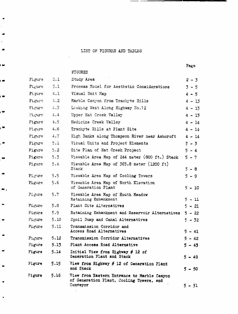
FiLme Figure
Figure
Figure
Figure
2.1 2.1 4.1 1.2
4.3 4.4
4 .5 4.6 ' I . .7 _, . 1 5.2 5.3 ,' . 4
-
r:
c'
5.5 5.6
5.7
5.a 5.9 5.10
5.11
5.15
5.16
LIST OF FIGURES AND TABUS
Page FIGURES
Study Area
Process Model. f o r Aesthetic Considerations
Visual Unit Map
Marble Canyon from Trachyte Hi.lls
LcokLig Vest Along Highway Mo.12
Upper Hat Creek Valle;?
Nedicire Creek TTalley
Trachyte Bills a t P l a n t S i t e
Xigh Benks along Thompson River near Ashcroft
Visual Units and Project Elements S i t e P l a n . of Hat Creek F?oject
Viewable Area Map of 244 meter (800 f t . ) S t ack
Viewable Area Map of 365.8 meter (1200 f t ) Stack
Viewable Area Map of Cooling Towers
Viewrble Ar4a Map of North Elevation of Generation Plant
Retaining Enbarhen+. Viewable Area Map of Houth Meadow
Plant Si te Alternat ives
Retaining Emba.nkment and Reservoir Alternatives Z p o i l h p and Canal Alternatives Transmission Corridor and Access Road Alternatives
Transmission Corridor Alternatives Plant Access Road Alternative
I n i t i a l View from Highway # 12 o f Generation Plant and Stack
View from Highway # 12 of Generation Plant and Stack
View from Eastern Entrance t o Marble Canyon of Generation Plant, Cooling Towers, and Conveyor
2 - 3 3 - 5 4 - 5 4 - 13 4 - 13 4 - 13 4 - 14 4 - 14 4 - 14 5 - 3 5 - 4 5 - 7
5 - 0 !5 - 9
5 - 10
5 - 41 5 - 42 5 - 43 5 - 49 5 - 50
5 - 51
TABLES
Impact Cause Xatriz
SummanJ o f Vis’lal Quality and Visual Impact
Project Element P r i o r i t y List Original Numerical Ranking of Visual Units Jormalized Numercal Ranking o f Visual Units
Sum o f Normalized Scores and Level of Visual Qual i ty
Numerical Ranking o f Visual Impact
Average Ranking of Visual Impact
Yisual Impact P r i o r i t y C r i t e r i a
. .*
I-
- . . .%.TLF 5-1 T:able 6-1
Table 6-2
Table A l . 1.
Table A1.2
Table A1.3
Table B 1 . l
Table E1.2
Table 21.3
5 - 3 6 - 3 6 - 4
A:l - 16 A1 - 16 A l - 17 B:L - 4 B:L - 5 B:L - 6
4” .

I-
Y
- . L . L
I
I ..,
The study o f Aesthetic Considerations involves: the assessment of the, present
v i sua l qua1i ty .h the s tudy a rea ; an eva lua t ion of the visuil impact caused by
specific elements of the Eat Creek Project: and the determination of measures
t o minimize the visual impact of project elements upon the visual qual i ty of the exioting landscape. Although p-oject actions during pre-construct:ion,
construction, operation, and decommission were reviewed, this study foouses
on the visual impact of elements that represent man-made components or disruptions on or i n the exis t ing Landscape.
The inventory of the s tudy area 's v isual qual i ty was completed a f t e r a s e r i e s
of ground and air observat ions o f t he p ro j ec t s i t e , and the analysis of topo-
graphic maps, aerial photos, and ot:her photographs of t h e s i t e . The study
area i s divided into ten visual units and two spec ia l fea tures tha t were
evaluated according t o a s e t of coraparative visual quali ty cri teria. These
c r i te r iam?reused t o a s ses s a l l t en v i sua l units, Those having outstanding
visual quali t ies included Marble Canyon and Upper Hat Creek Valley while
Cache Creek and Sighway # 1 r a t e d f a i r t o p o o r .
The project elements whose visualinlpactswere analysed are described i n a s e r i e s o f project reports prepared 'by 9. C. Hydro and Power Authority, INTEE E E A S X , and other consultants. Visllal impact importance i s assessed through the analysis of the! impacted areas, tne type of views, and the form and character-
i s t i c s of the project element's impact.
The most significant visual impacts are caused by the eleme'nts associatod with
the open p i t mine and the b lending fac i l i t i es . These project elements affected the visually sensit ive junction of the Marble Canyon, Upper Bat Creek and
Highway # 12 v isua l units. The recommended mitigation measures included. the
organisation of the project elements,. to nnarimize the separation betuaen this
1 - 1

I .
I *
8
m . 8
. . ,
1
e
.
,junction and these elements. 3erms are also used t o provide visual screens be'.wen Highway # 12 and the blending faci l i t ies . It is also rec:lz.lended that public access through the blending area be eliminated
b y providing alternative roujes t o the generation plant.
The next most s ign i f i can t impacts are caused by the elements associated
with the generation plant. These elements dominate the surrounding land-
scape which includes the Trachyte Hills and the Nedicine Creek Valley visual unit. Mitigation recommendations include the development of visual screens and th,? re locat ion o f the access road t o reduce the visual contact with the
ash dunp. The organization and development of the generation plant t o *::pres3 a high tecPno1oC-J emiromlent will provide an i r t e r e s t ing con t r a s t
tG the sxistir-g natural landscape.
The linkage elements such as the transmission corridor, the m a i n cocveyor,
and the access road create a s ign i f icant impact because of their l inet i r forms. C a r e f u l eodulation of the edges through the natural landscape will in tegra te
the man-made cuts with the natural. landscape. In addition i t is recommended
tha t the s tn lc tura l components of the transmission towers and the conveyors
Ue designed t o emphasize the l ineer l inkages between the various project
'?lements.
111 Chapter 5 . 3 other a l ternat ive m,easures and concepts are proposed. These
may o r may not be achievable within the technical and economic constraints of the project. However, they should be considered end evaluated in terms of t h e i r f e a s i b i l i t y as the project is developed since any mitigation measure
will contribute t o the overall reduction of this pro jec t ' s v i sua l inpac t . .
k
.
.
. :L - 2
2.0 INTXODUCTION
2.1 SCOPE AND PURPOSE
I .
. . I
I
. I
Y
In September, 1977, B. C. Hydro an,d Power Authority provided Toby Russell Buckwell & Partners, Architects, with the Terms of Reference for Architectural Advisory Services on the Hat Creek Project. An essential part of these services involved the development of a visual impact statement for inclusion in the Environmental Impact Report being prepared by a team of environmental consultants under the control and co-ordination of Ebasco Services of Canada Ltd., Environmental Consultants. The report is to provide documentation for license application, public hearings and overall project approval.
The objective of the visual impact statement is to define the visual impacts associated with the Hat Creek Project, identify which feature causes the impact, when and where it occurs, its significance and mitigation recolmendations. The principal imract causes are associated with project construction, project oFerations, and project decommissioning.
The statement follows an impact assessment approach which permits an inter- relationship of disciplines, axid which provides the input information necessary f o r the resource evaluationa.
2 - 1

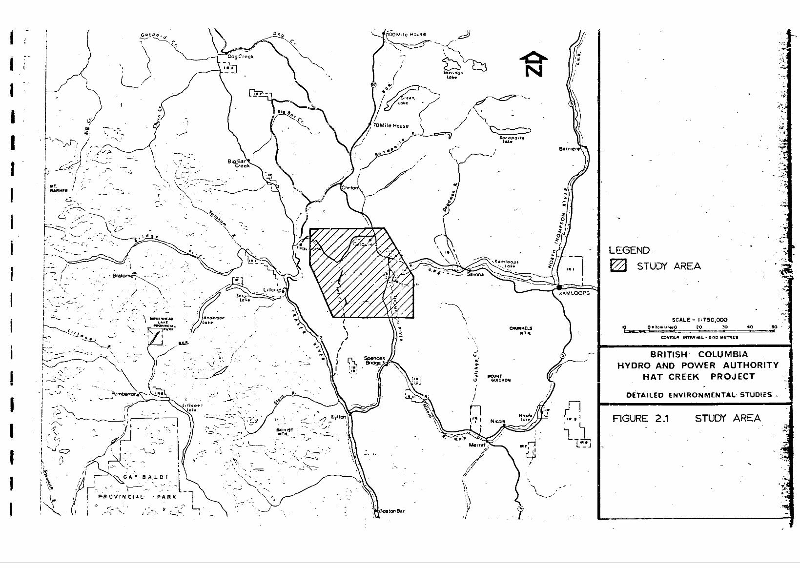
The study area is bounded on the north by an east-west line through a point I 5 km. north of Carquile; on the vest by a north-south line through Pcrvilion
I a p o i n t 15 La. south of Ashcroft; and on the east bg a north-south l ine para-
a d a l i ne pa ra l l e l t o Hat Creek; on the south by an east-west line through
le11 t o the Thompson River and highway #l . (See Figure 2.1 Study Bree.) .
2 - 2
LEGEND 5 STUDY A2EA
SCALE - I :750.000
BRITISH- COLUMBIA HYDRO AND POWER AUTHORITY
H A T CREEK PROJECT r
DETAILED ENVIRONMENTAL STUDIES .

2 . 3 PEXONNEL
4
Iu
Q-
The visual impact study has been carried out by a team made up of D:r. K. Shimizu of APRA - Advance Plapning an.d Research for Architecture (Co-ordinator),
Mr. R . L . Toby, Mr. T. S . Annandale, a. H. R . Ciccone, and Mr. J. :?umi of Toby Russell Buckwell e: Partners, Architects, Mr. Clive Just ice o f ,Justice &
Webb, Landscape Architects, and Dr. D. B. WilliaIcs of Forest Jlanning Systems
L t d .
2 - 4
3.0 STU3Y N?.TIiODOLGGY
"
. L W
"
a I
3.1 LITERATTJFtE REVIEW
The purposa of the l i t e ra ture rev iew was twofold. Firs t , i t enhanced the
understanding o f current visual analysis pr inciples , techniqtes , and s tudies
t h a t have been documented i n r e p o r t s ar.d periodicals. Secccd, i t provided
the oFportunity to become famil iar with aspects of the p ro jec t tha t have a
visual imFact on the study area. The l i t e r a tu re s ea rch and review was con-
d w t e d a t t h e l i b r a r i e s of the University of British Columbia, the University
of Washington, the Resource Analysis Branch of the Provincial Government, t he
Thermal Division of E. C . Hydro and Power Authority, and the co-ordinator of the ?nvironmental analysis, ESCLEC.
A review of t he methods f o r mea:mring and quant i fying aesthet ics , b y Martin .J. Hedding , describes visual analysis methodologies as: 1
". . . tools t o be used by a planning staff o r decision maker t o i d e n t i f y
a e s t h e t i c a t t r i b u t e s and forecast changes in the aesthet ic character-
i s t i c s i n the environment:, and to descr ibe the imp1icatior.s of changes
i n terms of potent ia l uses of environmental resources and environmental quality standards . It2
The visual analysis methods tha t were reviewed rarged from studies that ident i f ied general pr inciples and procedures t o ones t h a t developed a de ta i led method of visual imzact measurement. For example, the U. S. Forest Service,
which has comFleted a number of visual analysis s tudies , descr ibe a general procedure i n their publication, " V i 3 U a l Malaragement Systems.*t3 Luna LeOFOld's 4
study f o r t he U. S. Geological Survey is a very detai led analysis of environ- mental impact f ac to r s and is composed of a matrix containing 8 W ce:Lls. 5
3 - 1
I &
The Analysis/Interpretation Division of the Resource Analysis Branch in the Provincial Ministry of the Environment has also comgleted a numter of studies on visual sralysis. Their recent environmental report on the Northeast coal development contains a section on the visual resources of the area..6 The mathodology used by this Division reflects the current state of the art in visual analysis methodology.
From this :review of the literature on visual analysis, it is clear that there ie consensus abol;t methods f o r classifying and recording the visual quality of the natural environment. There is, however, less agreeeent on methods for measuring the visual impact of man-made elements on the natural environment. The basis for the visual analysis methodology that was developed for this study is the result of previous wcrk Completed by R. Burton Litton, Jr.7 and the Resource Analysis Branch. The parameters for using these two studies are given in the section oti Study Methodology.
A ComFrehensive site plan illustrating the project elements that have a visual impact was developed fron the rqorts and ongoing studies f o r all asFects of the project. For this initi.31 analysis of visual impact, the level of detail is 1.imited to one that clearly defines the project element's size, shape, an.d location. At this stage, detailed refinements are not required since they would be considered ,and integrated into the subsequent phases of the project's development.
3 - 2
3.2 STUDY METHODOLOGY
m-
1 I
... I
m m
The visual analysis methodology tha t was develoFed for th i s s tudy on Aesthetic Considerations meetsthe following cri teria:
( a ) The method should be as object ive as possible and r e f l e c t t h e
cu r ren t s t a t e of t h e a r t i n this f i e l d o f study.
( b ) It should cover a f u l l r a r g e of aes the t i c a t t r i bu te s inc:luding both man-made and na tura l components of the emironment.
(c) The f ac to r s and var iables used i n the methodology should be
appropriate t o the sca le and purpose of the study.
( d ) The method should be straightforward and be reproducible by others famil iar with visual impact analysis .
( e ) The r e s u l t s of the study s h o d d be i n a format that provides
meaningful input t o t he t o t a l impact analysis.
There are .three parts t o the approach taken i n this study on Aesthetic
Coxsiderations. The f i r s t t ask assesses bo th the ex is t ing visual q u a l i t i e s
and the visual s e n s i t i v i t y t o change of the landscape within the study area. The second task def ines the visual impact causes and t h e i r e f f e c t upon the
rwep to r s of the existing environment. The final task determines the import-
ance of the potential imract and develop courses o f act ion t o mitigate,
enhance, 03: compensate f o r i t .
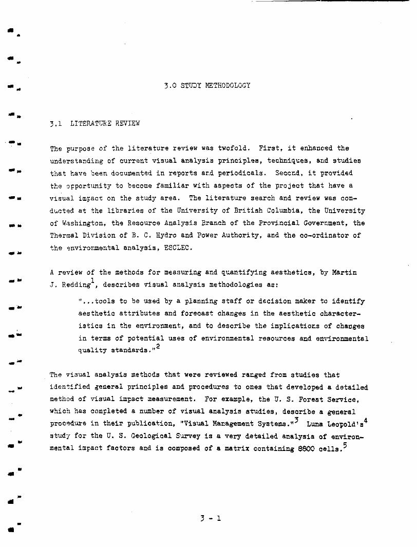
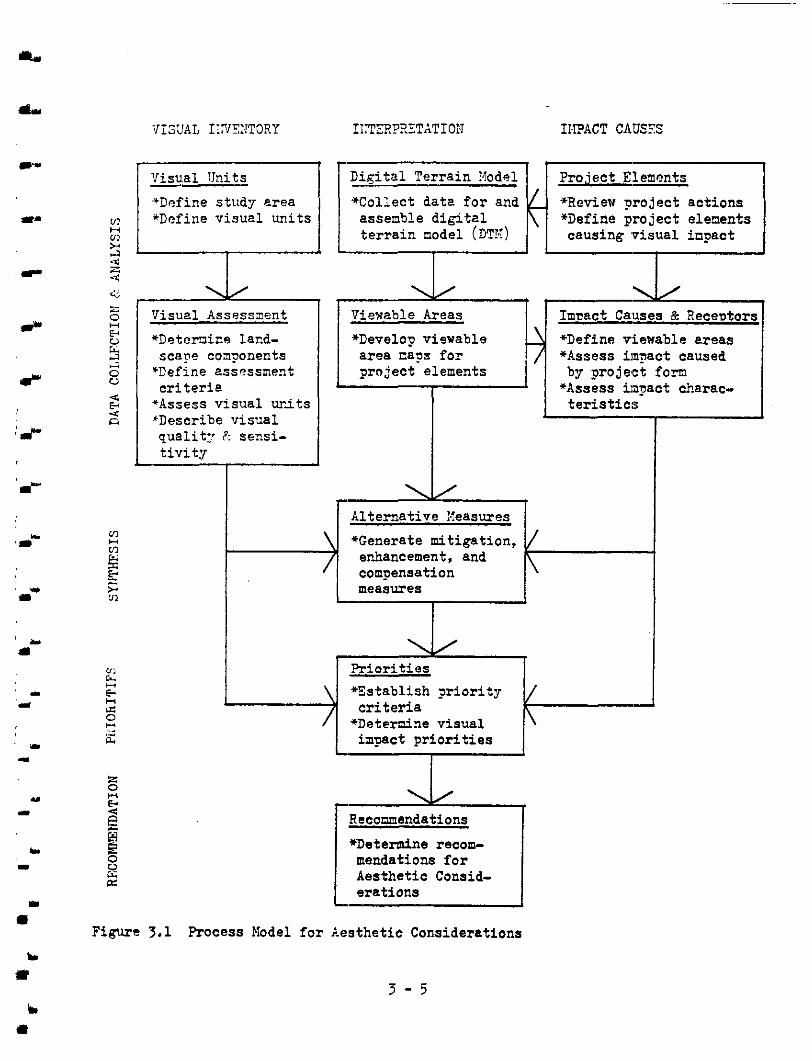
Figure 3.1 i l l u s t r a t e s t he r e l a t ionsh ips and seql;ence o f s teps tha t a re r equ i r ed t o fu l f i l l t he terms o f reference for this s tudy. The i n i t i a l
analysis o f the ex is t ing v i sua l qua l i t i es and the visual imFact of the project
elements are conducted independently. The synthesis between the ex is t ing
v isua l qua l i t i es and the profosed proiect elements occurs during th(3 inter-
pret ive phase where the importance o f a particular element 's isFact i s
? - ?
essesjed and courses of action are developed t o mitigate, enhance o r com-
pensate :For the impact. The recomcended courses of act ion are based on:
the exis t ing visual qual i ty cf a particular area; the relative importance
of a project element's impact t o a receptor when compared t o other inpacts;
t he f eas ib i l i t y of achieving a possible course of action.
Throughout this ana1ysj.s on Aesthetic Considerations, the interpretation,
evaluation and ranking of the vLsual quali ty, sensit ivity, and impact, are
asses sed i n t e rm of hot:. a var ie ty of observers are visually affected.
This review o f t t e stcd:i methodology describes the various tasks i n the study,
their l inkages t o each other, and t o the recomnendations. Each task i s des-
cribed i n d e t a i l ir, the following three sections of the report .
3 - 4
I)
Y
m
b I
VISUAL IY'PJTOIIY IIITERP3"tTdTIOiT II.PACT CAUSES
Digital Terrain ?!ode1 Project Eleaents
'Define studl erea *Collect date for and *Review y o j e c t a c t i o n s 'Define visuel units assemble d i g i t e l *i)efine project elements
H U! t e r r a i n node1 (DTX) 2
causing ,visual inpact . ~ . -4 x 4 e; i: a Visual Assessment Viewable Areas Imaact Causes & Receutors
5 *Detenir.o lacd- "Develo? viewable *Define viewable ereas
o *Define assossnerh scape coqonents area E6?S for *Assess imn?act caused
project elements c r i t e r i e
by p o j e c t f o r n
E "Assess v isua l ur-its t e r i s t i c s n *Describe visual
Y
r i 2 u 4,
4
*Assess impact charac-
qua l i t : P: sensi- t i v i t y
I
f Alternative Xeasures
*Generate mitigation, enhancement, and
measures compensation
. P r i o r i t i e s *Es tab l i sh J r ior i ty
*Deternine visual c r i t e r i a
impact P r i o r i t i e s
-
I
Recommendations
*Determine recom- mendations f o r Aesthetic Consid-
Figure 7.1 Process Model for Aesthetic Considerations
3 - 5

4.0 EXISTING VISUAL IFTEXCORY
4.1 COKPARATIVE ANALYSIS OF V1SCA.L QUALITIES
The evaluation of the ex is t ing v i sua l qua l i t i e s is based on t t Le prenis e t ha t
the three major sou-ces of visual reaction t o the landscape are i t ,s variety,
vividness, and u i t y . The doreinant fectors that s t imulate this reaction
are the form, l i n e , co lour , and textu-e of the landscape.
Variety holds the attention of the observe? and provides a richness and
d ivers i ty tha t maximizes the opportunities t o visually st imulate different
i n t e re s t g r o u p s . Vividness distinguishes the intensity of the visual ex-
perience by g iv ing d i s t inc t ion or producing strong visual cues t o the obser-
ver. Fina::.ly: unity provides the expression whereby parts are joined to- gether in to a coherent and s ingle harmonious unit stimulating 8 recN3gnizable
and memorable experience.
An objective evzluation of a viewer's response t o the visua: enviroxunent has been achieved, by using a system of c lass i fy ing and rating landscape com-
ponent;, ba,sed on the deeee of uni ty , var ie ty , and vividness present.
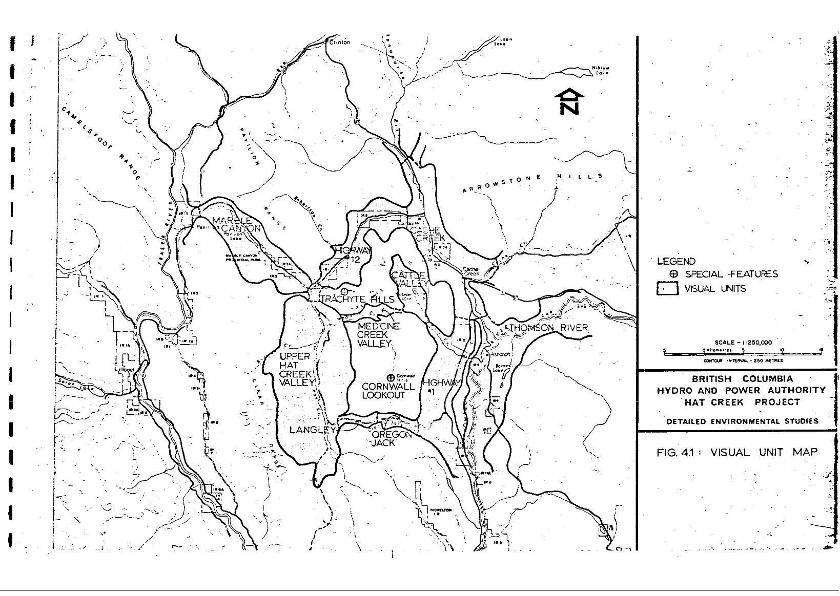
The visual un i t s , within the over821 landscape of the study area, wer$
idenfif ied in the first s t ep of the visual analysis. The v isua l units were defined as areas having a conticlous sense of enclosure and containi;g scenic
elements which provide unifying QI' dis t inc t ive qua l i t i es t o the 1end:scape. A chmacter i .s t ic of visual units is the topographic features, such &I ridge-
l i nes or distinct slope changes surromding low lying areas o r recognizable
val ley forms, t h a t define the i r boundaries.
A t rans i t ion zone o r por ta l occups a t t h e $ n c t i o n between two d i s t inc t ive
visual units. The narrow gaps at valley mouths and the passes betwee.n
4 - 1
d
i J
' L a
I L
. I
i. L
Y
r lli
val leys axe examples of porta:,s. A po r t a l may heighten the aesthetic ex- Ferience of a v i sua l unit's qua l i ty by defining a mique approach o r s p a t i a l
sequence t o a v isua l un i t .
The scenic elements o r landsca?e components that define the characterjst ics
of each v i sua l unit are tke boundary def ini t ion, general form, terrain
pattern, visual features, vegetation patterns, water presence, and cu l tu ra l
and land use patterr..
Boundary def ini t ion deals with those character is t ics which
visual ly es tabl ish the per imeter or edge of the unit within
the general area. Edges are created by the interface between
skyline and ridge, horizon and plane, o r other toundary cm- d i t i ons that provide H visua l edge t o a unit.,
General form re la tes p r imar i ly t o the expression of the lctndform
such as mountains, planes and depressed o r bowl-like containments
su.ch as va l leys arid ba.sins.
"-
Terrain pattern emerges through r epe t i t i on of form-shape-colour-
texture var ia t ions. It can vary from soft undulating hills t o mountainous t e r r a i n ,
Visual features are those elements within the visual unit tkat
stand out through dominant scale , i solat ion, d is t inct ive shape, o r other special Characterist ics such as surface contrast and variat ion.
Vegetation patterns assist i n determining landscape character by def ining par t icular kinds o r composition of vegetation cover
having dist inctive colour, texture, and density,
Water presence within the visuel unit provides another &stin-
.Wishing feature that general ly enhances the observer's aesthetic
4 - 2
esperience.
( E ) Cultural and land use patterns indica'.e the presence of human
occupation as characterized by field crops, pastures, grazing
areas , roads, and other man-made elements. The form, t ex tme ,
sca ie and colour of the man-made changes can enhance or degrade
the qual i ty of t h e v i s u l e x p e r i e n c e .
Within the defined visual units (Fig. 4-i), the degree of unity, vaniety,
and vividness present in each landscape component was evaluated. The basis
f o r the evaluation vas the comparative visual qualities described in Appendix
A . The higher quali ty was assigned a numeric rank of 7 and t t e lower qua l i ty
a rank of 1 . A numeric rank of 4 indicated an average quality f o r the study
area. Each landscape componer.t o f each v isua l unit w a s rmuiked. The sum of the scores f o r uni ty , var ie ty , and vividness within each visual u n i i ; deter-
ztined i ts ranking re la t ive to the other wits in the s tudy area.
Although this numerical ranking represents a quantifiable procedure f o r es tabl ishing the overal l v isual qual i ty , i t st i l l required subjective value
judgments and reflects the biases sf the observers i n terms o f t he i r cu l tu ra l
background, the context o f t h e i r CbSerVatiGnS, and the sensit ivity- o:f the
observers t o different environmental stimuli. The numeric rankirg (of each
v isua l unit was qual i f ied by a description of i t s overall visual quaLity created by the combination of a::! the landscape components. T h i s combined
experience could reir-fcrce the vi.sual concepts of enclcsure, enframernent,
panoramic view, end focal point. It also ident i f ied how landscape components
have teen or,Ganized t o enhance the visual experiences o f s p a t i a l sequence,
contrast, convergence, and an ax ia l approach.
In conjunctioc with the description of visual qual i ty , a v isua l u n i t ' ! 3 sensi-
t i v i t y t o ==.-made changes iras qualitatively evaluated. The visua: , -eunitivity
evakat ion assessed the capabi l i ty of the landscape t o absorb change or modi- f icat ion.
4 - 3
I .
.I . .
I
. Y
One factor that defines a unit 's v i s u a l s e n s i t i v i t y i s the numeric ranking of its v i sua l qua l i t i e s . A high rank indicetes a ver: sens i t ive a rea where
man-made clzanges wculd disrupt the overall q1;alities of unity, var ie ty , and
vividness. However, this does n o t mean tha t a low numerically ranked visual uni t is not s ens i t i ve t o change. There a-x o';her contr ibut ing factors that a f f e c t s e n s i t i v i t y . These f ac to r s a r e r e l a t ed t o the charac te r i s f ics of the
seven landscape components.
The sens i t i v i ty r e l a t ed t o the landscape conponents is caused by thme way
ckani:e is displayed o r exposed t o the observer. The following c r i t e r i a a r e
usad t c assess this aspect of v i sua l s ens i t i v i ty . It completes thi:j ir,ven-
to ry of v i s u a l q u a l i t i e s by de f ix ing ex i s t ing v i sua l qua l i t i e s and where
tkey are most sens i t ive t o change.
(a) Changes occurring on higher locations became more apparent,
to an observer than ones that occur along a val ley f l o o r .
( b ) The greater the sideslope the greater the exposure of changes
that occur on i t .
( c ) Ridgelines and skylines are sensit ive to chmge because of the manner in which i t i s displayed.
( d ) Changes !;hat occur a l o n g shorelines and water courses are
sensitive because of the exposure and contrast between man- made and natural elements.
(e) Vegetative type, texture, and pat te rn a f fec t v i sua l sens l tkr i ty .
A heavily treed area provides a visual screen while the uniformity
of the bunch grass ranges i s highly sensi t ive t o modifications
that occur on i t . A treed area i s a l so sens i t ive t o changes1 such
as clear cut logging operations and transmission line corrid.ors.
I *
. t
4 - 4 . I
t t t I I I I I I 1 I I 1 I I I 1 I I
i
LEGEND \
~ SPECIAL FEATURES 0 VISUAL UNITS
SCALE - I:2SO,coO
BRITISH COLUMBIA HYDRO AND POWER AUTHORITY
AI LKccn r K u J c c . ~
DETAILED ENVIRONMENTAL STUDIES
c .." ""., nnc. ,r"r 4
~
FIG. 4.1 : VISUAL UNIT
?he -Jicluul units sescr i led i n the f o l l o w i n g assessment are defined i n Fig. 4-1. Each visual unit evaluation f o l l o w s t h e c r i t e r i a i n Appendix A an~l is based on an analysis involving interpretation of a e r i a l photos,
extminaticn of 1:50000 topographic maps, f ie ld reconnaissance a t ground leve l and from a helicopter, review of s i t e photographs, and a review of
pertinent regorts by project consultants.
The visual oual i ty of each v i sua l unit is independertly evaluated acconiing
t o the cr!.terl& i.c Apperdix A-1 by three members of the stcdy team. The visual units that were eva lua ted fa l l i n t o f o u r different categories of'
visual qualiky. A t the highest level are those visual units having outstand-
ing o r unique visual qualit ies. Ned are those units u i t h high or abam averag? visual qual i t ies . The t m d group are those units with average v isua l qua l i t i es and f ina l ly , there a re two visual units having fair t o pOlJr visual qual i t ies . (See Appendix 81.2 f o r detai led analysis) .
The ten visual W t s that are evaluated are shown on f igure 4-1. Thesse visual units a re determined from the topographic features which describe areas having a continuous sense of enclosure. A field observation of .the study area verified the extent and location of the visual units. They :in-
clude Narble Canyon, Upper Hat Creek Valley, Wedicbe Creek Valley, Cat.:le Valley, Eighway #12, Cache Creek, Thompson River, Highway #1, Oregon Jack and Lmgley. In addition obsema?ions are also made of two special fea?ures: Cornwall Lookout and Trachyte Hills.
( i ) Marble Canyon - V i s a bality: Outstanding
In the k b l e Cenyon v i s u a l unit a number of landscape

components has been combined i n t o a d i s t inc t ive end
highly unified visual experience. The well-defined
and controlled entrance and gateway a t the eas te rn end of Marble Canyon dramatizes the Tdsual experience
and enhances the uniqueness of the valley. The canyon
with its narrow ~n t r ances , cha in o f lakes, and sheer
canyon walls has received provincial recognition by being designated a provincial park.
Marble Canyon with its unique scenic qualities is also highly sensit ive t o nan-made developments along i ts steep slr ,pes, r idges, and the shoreline of i t s lakes. Development i n such areas could disrupt the existing
uni ty and harmony of' the area. However, the area can
a l s o absorb man-made chaxlges when well 'handled. For exanple, a cabin, sc:reened by vegetation and b u i l t cn the i s l a n d in PaviUion Lakc, adds variety and i n t e r e s t
t o the landscape without disrupting the existing visual
harmony. The limestone quarry provides an example o f how the exis t ing visual qual i ty was degraded and dis-
rupted. A t this s i t e no attempt has been made t o provide
n?itigati.cn measures t o preserve the integrity of the scenery.
(ii) Upper Hat Creek Valley - Visual Quality: Outstanding
In contrast t o Marble Canyon, the Upper Hat Creek Valley is
broader and has less vivid features and edge def ini t ion. O n
entering the valley :from the north, the landscape consists
cf both man-me.de and natural landscape elements. The ranches, pas tures , i r r iga ted f ie lds and fencing have greatly
enhanced the visual qual i ty by adding contrast , variety, and
texture t o the vegetative pattern of a t y p i c a l v a l l e y i n t h i s
region. Additionalkf these complementary man-made fea tures
4 - 7
prcvice an easily ide:ntifiable scale along the broad
va l ley f loor . The outs tanding visual qual i ty of this val ley is a t t r i bu ted t o the integrat ion o f man-made
ar.d natural elements into a unified visual experience.
Within this broad va1:ley f o r m , s a j o r developments wfich
d o n o t respect the esrablished scale along the valley
f loo r will have a high impact on the v i sua l vu lnerabi l i ty
o f the area. ?he rol:.ing h i l l s that define the edge of
this visual unit are capable of absorbing changes which
can be screened o r integrated with the existing landforms
and vegetative pa2tern.
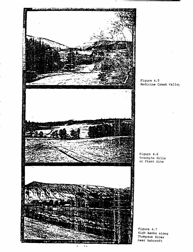
( i i i ) Medicine Creek Valley - Visual Quality: Eigh
?.he man-made and natural landscape components of t h i s
visual un i t a r e simihr t o the Upper Hat Creek Valley
v isua l unit. Differences occw i n the scale and more
def in i t ion of natura: fea tures of the Medicine Creek
Valley. In its 5.5 la. length the visual experience
includes a small mountain lake, open range land, a small ranch, and a narrow V-shaped valley with a small creek.
Both the neavily treed, steep north slope and the ro l l ing ,
open south slopes o f M'2dicine Creek are highly vulnerable t o man-made developments. A n y m j o r development could
domir-ate and obscure ?!ne exis t ing visual amenit ies of the vi.sua1 unit .
( iv) Cat t le Val ley - Visual Guality: High
Cattle Valley also provides a high q u a l i t y visual experience. ?ha visual s ignif icance is derived from the contrast between
the entrances, which are s teep, narrow, and heavily treed,
4 - 8
and the openness and pastoral qual i ty of Cattle Valley
v isua l un i t . McLeAn Lake dominates the southern end of
this val ley which has many v i sua l qua l i t i e s sirnil= t o
the Cpper Hat Creek Valley.
The areas most mlnerable t o development i n t h i s va1le;y
are alcng the steep-side slopes, the open graz ing land
and the lake shoreline. Large cuts through the nar row entrances could a l s o destroy the total i ty of the visua:l
experience. Developments can occur in se lec ted a reas
without disrupting the exist.ing harmony, and i n c e r t a i n
places may provide opportunities f o r new vistas am3 vimal
display.
(v ) Highway # 1 2 - Visual Quality: Average
The Highway #12 corr idor , from Highway #97 t o Marble Canyon,
f o l l o w s the route clf Hat Creek. Within this v i sua l uni.t there are small ranches and farms, power l i r e s , and a high-
way t o contrast wi th the natural features of the valley. However, these man-rade elements do n o t provide the variety
and i n t e r e s t that are created i n the Upper Hat Creek o r Cattle Valleys. Instead they tend to disrupt the existing v isua l un i ty and harmony and lower the Trisual experience t o
an average quality level.
Developments along the narrow val ley f loor and steep side
slopes of this v i s u s l unit would have a high visual imp.%ct
on the exis t ing environment. Development could OCCCT ix cer tain areas which are naturally screened from the exis t ing
highway and other viewpoints i n the visual unit. The e:dst- ing highway is an example o f a man-made element that disregards
existing landforms and vegetative pattern by makixg large cuts and f i l l s wi th very l i t t l e a t tempt a t revegeta t icn .
4 - 9
( v i ) Cachc Creek - Visual Quality: Poor
The Cache Creek v isua l unit follows the valley and the
water course of the Bonaparte River. The unifying ele-
ment o f the are'a i s the r iver and 'its associated vegetative
pattern. I n the northern part of this unit the presence! o f farms provides a v isua l ly in te res t ing cont ras t t o the barren
h i l l s . However, the visual esperience i s dominated by the
commercial and r e s iden t i a l developments i n Czche Creek.
These man-made changes have not responded t o the naturel.
amenities o f the area. In their p lace a development has
been created that lacks visual cohesion o r i n t e r e s t .
The lack of vegetati,ve cover on the hills surrounding t h i s v i sua l unit makes them highly vulnerable t o any
man-made changes. Although %he existing pattern of derelop-
ment has tended t o d.egrade the visual experience, any new
developments could begir t o improve the ex i s t i rg v i sua l
quali ty through careful si t ing and screening.
( v i i ) Thompson River - Virlual Quality: High
This visual unit is dominated by the Thonpson River which becomes i ts unifying element and its predominant feature!.
Along this corridor natural features such as the sandstone
c l i f f s , Black Canyon, and the r iver add var ie ty and in t e re s t .
Certain man-made elements like the small farms complement
the exis t ing natural. qual i ty . However, the natural harmony
o f the valley has been disrupted by Ashcroft 's new sub- divis ions which appear scattered and out o f character wi.th
the t e r ra in and the older areas of the community. In tke
overall perspective, the strength m.d s k p l i c i t y of the r i v e r ' s visual experience dominates tAis visual unit.
4 - 10
In general, the exposure of developments w i t h i n this
unit creates a s i tua t ion of high visual impact. The
contrast between the barrcn hills and the new Ashcroft
subdivisions demonstrates this vulnerabi l i ty . Like Cache Creek, any new developments must be sens i t i ve t o
the visual character of the area.
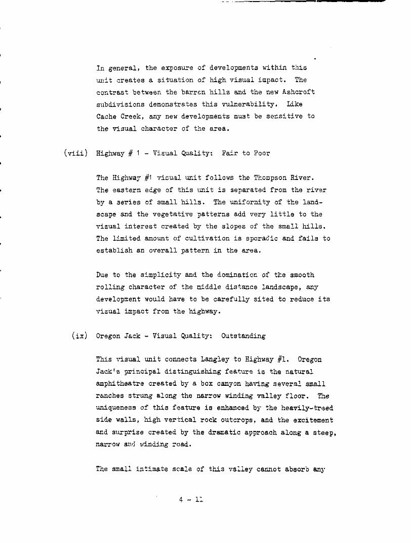
( v i i i ) Highway # 1 - V i m a l Quality: Fair t o Poor
The Highway #t visual unit follows the Thompson River.
The eastern edge of this unit is separated from the r ivs r
by a s e r i e s of small hills. The uniforni ty of the land-
scape and the vegetative patterns add very l i t t l e t o the
v isua l in te res t c rea ted by the slopes of the smell hills.
The limited moun t of cu l t i va t ion is sporadic and f a i l s t o es tab l i sh an overal l . pat tern in the area.
Due t o the s implici ty and the domination or' tke smooth
ro l l ing charac te r of the niddle distance landscape, any
development would ha.ve t o be ca re fu l ly s i t ed t o reduce i.ts
v isua l impact from the highway.
( i x ) Oregon Jack - Visual Quality: Outstanding
This visual unit connects Langley t o Highway #l. Oregon
Jack's pr incipal d is t inguishing feature i s the natural amphitheatre created by a box canyon having several small
ranches strung along the narrow winding val ley f loor . TIe uniqueness of this feature i s enhanced by the heavily-treed
s ide walls, high ver-tical rock outcrops, and the excitement
and surprise created by the dramatic approach along a steep, narrow an3 vinding road.
Tne small intimate scale of this valley cannot absorb any
4 - 11
mator developments. These changes would destroy the ex is t ing v i sua l un i ty and harmony. Minor modificetions
along the valley f l o o r can be made without degrading ep is t ing v i s tas .
(x ) Langley - Visual Quality: Outstanding
Langley comects the south end of the Upper Hat Creek
Valley t o Oregon Jack. It ra tes h ighly as a scenical ly
d i s t inc t ive v i sua l unit due t o thP vivid contrast between
the very narrow -ral.ley floor containiag Langley Lake and
some farm land and the very steep escarpments enclosing
and u n i f y i n g a l l th,e landscape components. In sca le ,
Langley is not as overpowering as Marble Canyon, yet ha.s
many o f (.he same features which provide such an outstanding visual experience.
Unlike Marble Canyon, Langley caraot absorb developments because of i t s r e l a t ive ly small scale . Any change along
the steep slopes would be exposed t o the other parts of
the valley and would destroy the eBisting uni ty and hannony.
Modifications t o the valley f l o o r would have t o be mode:3t t o reduce the visual inpact.
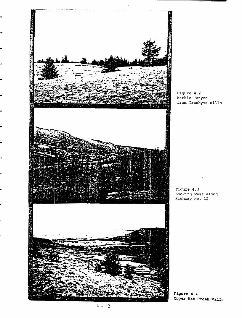
Figure 4.2 Marb:Le Canyon from Trachyte
Figure 4 . 3 Looki:ng West a. Highway NO. 12
Figure 4.4 Upper Hat Creek
Hills
long
Valle '4 - 13
4.3 SPECIAL l?3ATURES
Ttc nature o f the landscape and ths charac te r i s? ics of the project develcp-
ment indicated the need t o include features within the study area which were
not within the defined visuel units. The two special features descr ibed
below a r e the Cornwall Lookout and the Trachyte Hills.
The visual qual i ty ass igned t o the two special features i s determined from
a comparative aEalysis with the vi:;ual units. The q u a l i t a t i x d e s c r i p t i o n
indicates the genera! visual qual i - ty o f each special feature because c:citeria
f o r landscape components a re not applicable t o e i t he r Corowali Lockout o r
Trachyte Hiils.
(a) Cornual1 Lookout - Special Feature - Visual QJality: Outstandirg
The Cornwall forestry lookout provides a spec ia l and unique visual
experience t o the stud7 area. Located on the highest point within the study area, i t produces a majestic panoramic view extending f r o m the snow-capped Coast Range on the west and south-west t o the
Highland Valley and the I’nompson Lake val ley t o the east and north-
eas t . Below the lookout there i s a unique vista of the Thompson
River, Ashcroft, and the exis t ing pat tern of the valley f l o o r .
To the nor th , the Trachyte Hills dominate the yrista from the look-
out. However, i t is the rugged fea tures of the Coast Range and the a b i l i t y t o look down at the Thompson valley that provide the m- surpassed vistas from the lookout.
(b) Trachyte Hills - Special Feature - Visual Duality: High
This special feature was :selected bacause of its signif icance to the development of this project. Although the Trachyte Hills extend
along the Highway #I2 corzidor, this obsemation focused on that p a r t
4 - 15
o f the Tzachyte Hills that has beer. proposed as t he p l an t s i t e .
The ar+a contains both treed and open arean. From varions points
around the pr0pOSed plant s i t e , v i s t a s of Highway #12, Marble Canyon, Upper Hat Creek Valley, and Medicine Creek Valley c m be
seen. Tne predominant views a x down t o Upper Eat Creek, Marble
Canyor, and Highway #I2 junction.

4.4 ASSESSMENT CONCLUSIONS
The visual assessment o f the study area provides the framework f o r the
following evaluation of visual icpact and recommendations regarding measures
that could be taken i:o reduce o r e r h c e this impact.
In general , the visual units and spec ia l fea tures of the study area are
unique t o the region. They contain a var ie ty of 0utstandir.g visual fea tures
that have been L-rouped. and linked together t o provide a unique visual experi-
ence t c a l l cbservers whether they be r e s i d e n t s , t r m s i c n t s , o r visitors. The following sections describe the neaswes by which this visual experience
csa be maintained o r enhanced a s a r e s u l t o f the development of the Hat Creek
project..
4 - 17
5.0 IMPACT CAUSES AND THEIR RECEPTORS
5.1 IMPBCT ASSESSMENT
The purpose o f this sec t ion is t o d.efine the project elements that cause e visual impact and t o determine the char8c::eris:;ics o f this impact upon the
receptcrs . The receptors re fe r red t c a re the a f fec ted visual units 8r.C. the
special landscape fcatures o f the study area.
Each "project action" l isted in the Detailed Environmental Studies
Terms of Reference was reviewed t o determine the physical elements required
f o r implementation. The physical elements that were func t iona l ly re la ted
and that could be grouped i n t o clusters are considered as s ing le en t i t i e s .
This r e tuce t t he number o f elements f o r assessment and provides an oppm.rt,Un-
i t y t o assess the impact cause? by 13 group of elements. There are exceptions
t o this groupicg of elements, and they occur when the scale o r form of a
single element dominates the group. For these exceptions the group is 13s-
sessed without the dominating element, and the visual impact o f the latter i s considered by i t s e l f .
The first s t e p cf the assessment process is the d e t e r h a t i o n of areas from
nkich a pro jec t element could be viewed. The areas are def ined from a sltudy
of the location of project elements on topographic maps and aerial phot+ graphs, f r o m th'e visual inventory taken on t h e s i t e visits, and from the
computer-based .terrain ana lys i s model that developed viewable area maps f o r specific project elements.
The f o r m of a project element descri'bes i t s phys ica l qua l i t i es of shape,rnass,
and s t x c t u r e . In this study, form ;also r e f e r s t o the linear elements such as the transport:ation and s e r v i c e c a ~ ~ i d o r s . The form described by a group
of elements def ines the spat ia l organizat ion among individual elements.
5 - 1

The assessment of how the form of a project element visually affects the receptors i s based on the evaluation of whether a prcject element either con-
forms t o or disrupts the receptor 's v isual qual i t ies . Appendix B1.l de-
sc r ibes the fac tors tha t were considered t o determine whether the form
cont ras t s or complements t he s e t t i ng i n which i t is lccated; dominates
o r is consiste:nt with the erzisting visual q u a l i t i e s of the receptors; and
degrades o r enhances the . ex i s t ing s e t t i ng .
The cha rac t e r i s t i c s of the visual impact caused by a project element con-
sist o f a l l the other factors, with the exception o f i t s form, tha t
vi3ually affect the perceived quali ty o f the existing environment. In the
evaluat ion, t te nature of t he e f f ec t s of the impact causes was assessed and
includes such fac tors as whether the charac te r i s t ics o f the visual change
a re e i the r i r r eve r s ib l e or reversibl.e, whether i t contrasts o r complements
the exis t ing set t ing; and whether i t : degrades or enhances the surrounding visual qual i ty . (See Appendix B1 .1) .
5 .- 2

.
-LEGEND -VISUAL UNITS . . - . 1 MARBLE CANYON 2 UPPER HAT C E K VALLEY
4 CATTLE VALLEY 5 HIGHWAY "12 . 6 CACHECREEK
8 HIGHWY * 1 9 OREGON JACK
- 3 MEDICINE CREEK VALLEY
7 THOMPSON RIVER
10 . L A N G L E Y
"
SPECIAL FEATURES 11 CORNWAU LOOKOUT 12 TRACHYTE HILL
SCALE - 1:250.000
BRITISH COLUMBIA HYDRO AND POWER AUTHORIT1
H A T CREEK PROJECT
DETAILED ENVIRONMENTAL STUDIES
FIGURE 5.1 VlSWc UNITS AND PROJECT ELEMENT
. . .. c ,.
.. . . i
.. w . -
SCALE- 1.50.000 I 0 Kilemelr.. I :
MNTW INTERVAL - I00 MET=
BRITISH COLUMBIA HYDRO AND POWER AUTHORITY
HAT CREEK . PROJECT .~ -.
~~
. DETAILED ENVIRONMENTAL STUOIES
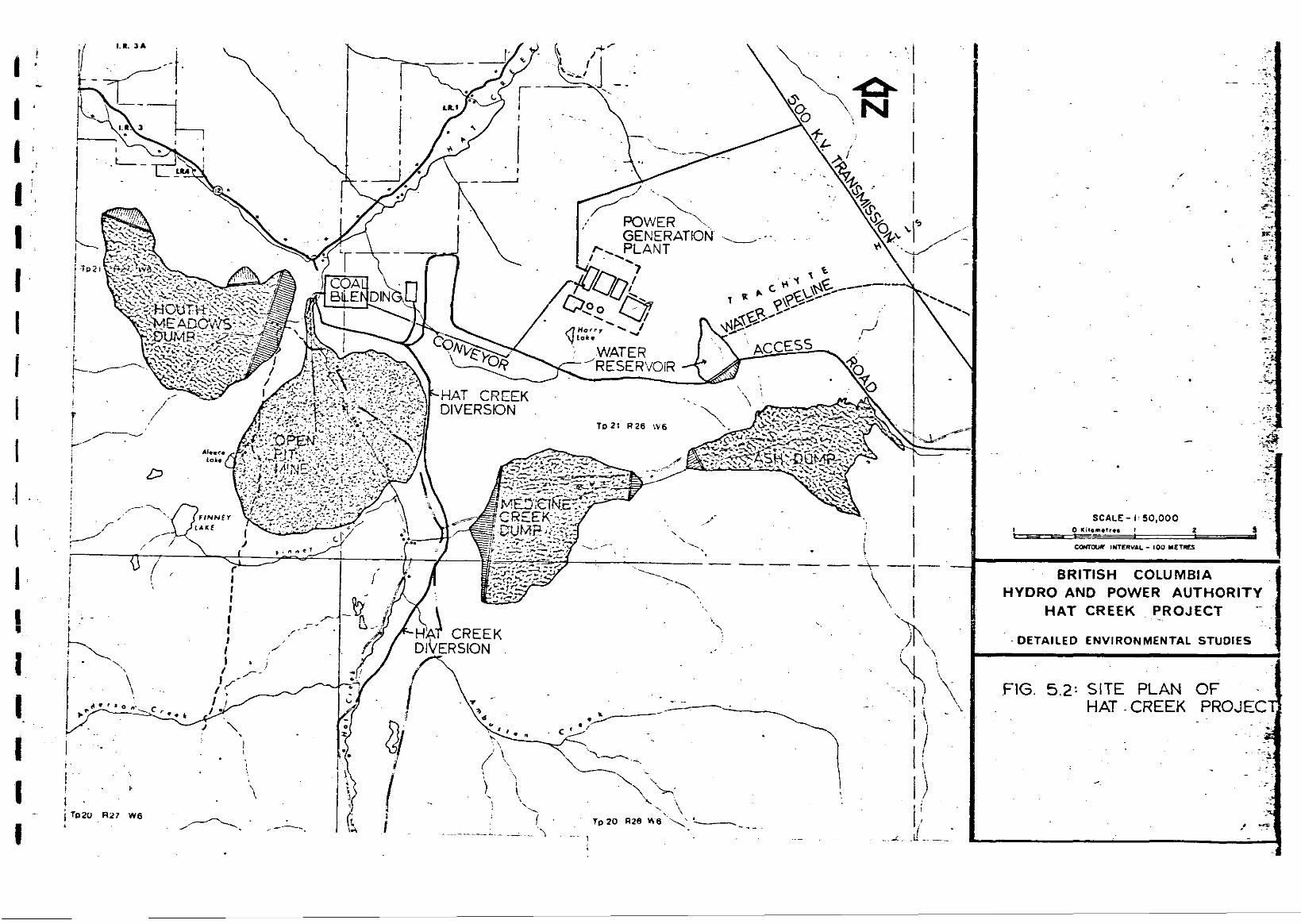
FIG. 5.2: SITE PLAN OF HAT -CREEK PROJEC
5 - . . .~
. . . /
-
;. , y
m
5.2 VISUAL IMPACTS AND ALTERNATIVE: MEASURES
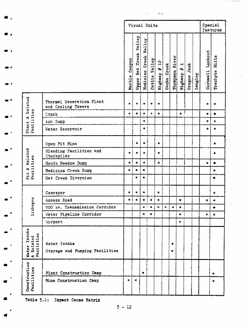
The impact came matrix i n Table 5.1 iden t i f i e s t he v i sua l ly impacted 6Lreas
and the pr0jec.t elements that cause the impact. The following analysis
groups the pro.ject elements under five major categories. One group consists
of the plant and r e l a t e d f a c i l i t i e s , a n o t h e r t h e p i t and r e l a t e d f a c i l i t i e s ,
a t h i r d group :is the linkages, a fourth the water intake fac i l i t i es , ar.d the
l a s t group i s the cons t ruc t ion f ac i l i t i e s .
I n general, tho focus of the visual impact study is on the operation ph.ase
of t ne development. During the pre.-construction and construction stages the visual impact would be too dynamic to propose meaningful mitigation o r enhance-
ment procedureei. Therefore the visual impact i s sues a r e ch i e f ly concerned
w i t h the qua l i ty of the b u i l t environment and not with the process by which i t is created. During the decommission phase the concerns o f t he v i sua l environ-
ment would be t;o reclaim, to the extent possible , the visual qua l i t i e s ex i s t ing
before the in i t ia l phases o f th i s p ro jec t ' s development. I n c e r t a i n s i t u a t i o n s
the reclamatioa. may be i n the form of compensation measures such as t h e develop-
ment o f a new lake o r new access roads t o the recreat ion areas .
For each individual or group of project elements a descr ipt ion of i ts physical
cha rac t e r i s t i c s , t he v i sua l ly impacted areas, and the mit igat ion, enhanoe-
ment, o r compensation measures are described before determining the recommen- dations which appear a t the conclusion of this study. The views f r o m the
receptors are descr ibed as foregourtd (up t o .8 ian.), middleground (up t :o 5 km.), and background mor d i s t a n t views. Mitigation, enhancement, and compensat:ion
measures are a lso descr ibed i n the same terms. Foreground views are those that occur i n t h e immediate v i c i n i t y of the observer. Middleground views occur a t distances where form, l ine, colour, and tex ture o f the landscape and man-made
elements are s t i l l observable. Background o r d i s t a n t views are those concerned
with long v i s t a s of t he skyline o r ridgeline of hills and mountains where the
shape o r s i l houe t t e of objects become the i den t i f i ab le f ac to r .
5 - 5
- L
.-
I '
This grouping: of views and measures provides the opportunity of developing
n i t i ga t ion , enhancement, o r compensation actions that would apply t o the
appropriate views of the impacted area.
The impact cause matrix i n Table 5.1 was developed from the data col lected
i n the f i e ld , from topographic maps and aer ia l photos , and from the computer
based viewable area maps. The computer was used t o generate maps of project
elements whose viewable areas were d i f f i c u l t t o ascer ta in . These e k u e n t s
are the stack:, the cooling towers, the.generating plant structure, an'd the
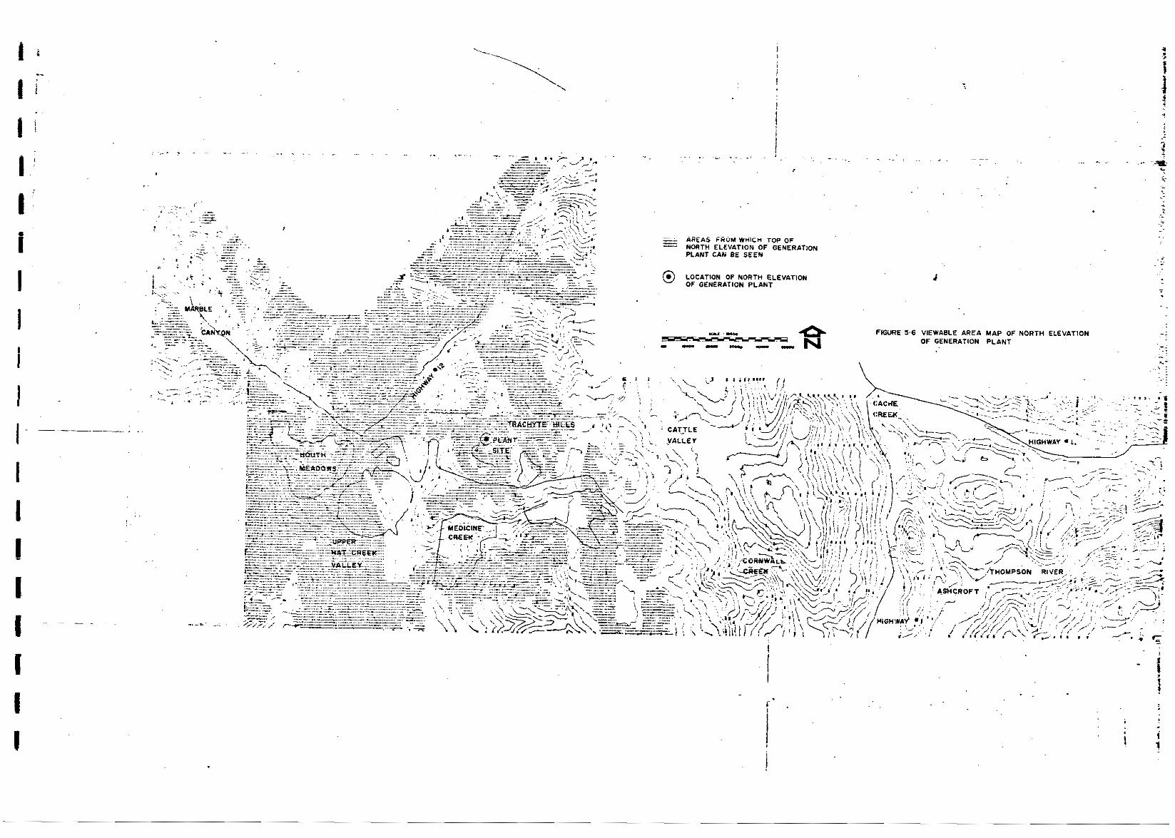
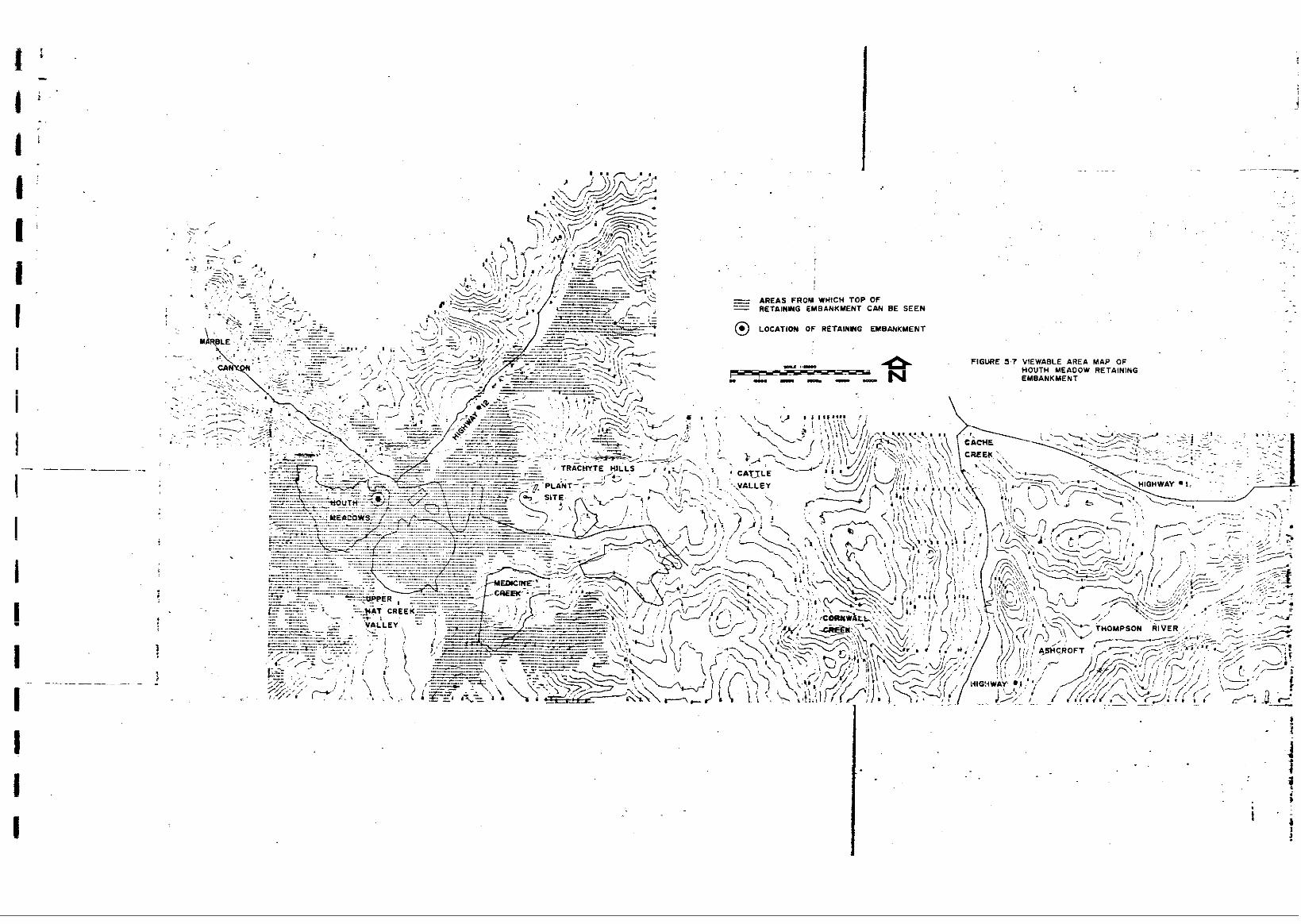
re ta in ing emtankment of the Houth Meadow Dump. Figures 5.3 t o 5.7 repre-
sent the compter viewable area maps o r areas from where the project element
can be observed.
For example, the dotted areas on Figure 5.3 represent the locations f:rom which
the top of the 244 meter (800 ft.:) stack can be seen. The areas not (dotted
on t h i s topopaphic map are those locations from which the stack cannot be
viewed. Based on t h i s computer generated map, the 244 meter stack wi:ll not be
seen from the lower areas of Marble Canyon and Highway #12, as well 883 Cache
Creek, Highwa.y #1 and the Thompson River. Similar interpretations have been
made for Figures 5.4 t o 5.7 and form par t of th i s s tudy ' s ana lys i s of the
v isua l ly impacted areas surrounding the si te.
5 - 6
.
"
. .- STACU CAN BE SEEN AREAS FROM WHICH TOP OF
@ LOCATION O F STACU
,

.. . I . . - .. . . . . i
i
!
I; t i ' I
I I ! I' I I I I
.. ~. . . .
AREAS FRUU Ylt+icn TOP OF
PLANT CAN BE SEEN NORTH ELEV4TION OF GENERATION
-
@ LOCATION OF NORTH ELEVATION OF GENERATION PLANT
FIGURE S.6 VIEWABLE AREA MAP OF NORTH ELEVATION OF GENERATION PLANT
.. "
-
,
1
, I
Thermal Generation Plant and ICooling Towers
Stack
Ash 13mp
Watex Reservoir - I P i t Mine
I Z I Blending F a c i l i t i e s and Stockpiles
Hout:n Meadow Dump
Medicine Creek Dump
Hat Creek Diversion
- - -
Corridor
:dater Pipeline Corridor
.Airport
l a ! I t ? Y , r a w c a 4 H Y Y
& A d a! a! .*
m .* Mater Intake + = v Stomge and Pumping F a c i l i t i e s S & $
- Table 5.1: 1:npact Cause Xatrix
r .. 1
Visual Units
* -
* - * - * * - *
* - *
*
5 - 12
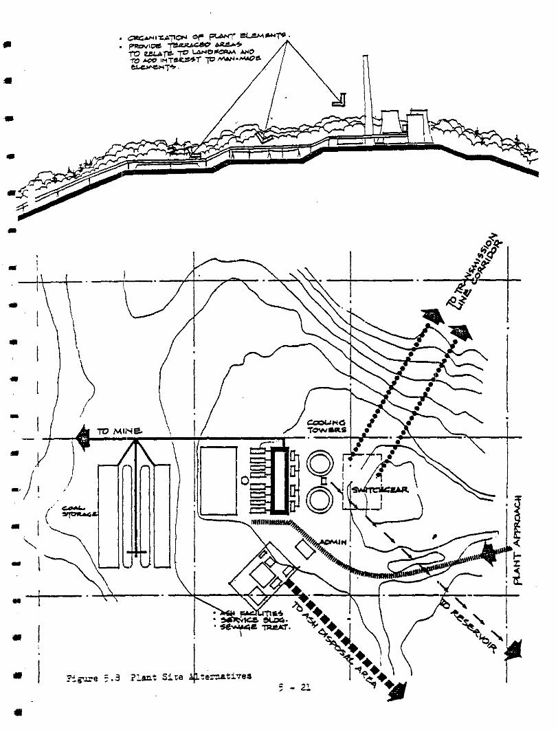
5 . 3 ALTERNATIVE MEASW3S FOR PLANT AND FGUTED FACILITIES
*-
.I-
a-
m -
"
*-
I L
(a) TEERMAL GENERATION PLANT AND COOLING TOVERS
(i) . Phys ica l Cbzac ter i s t ics of the Thermal Generation Plant and Cooling Towers
Included i n t h i s group of project elements are the suitchyarcl, the towers, and the cables required t o t i e i n t o tho 500 kc.
corridor; the power plant consisting of the turbine hall ,
the boiler plant, and the precipitators; the buildings f c r
administration, service, and warehouse; t h e f a c i l i t i e s f o r
ash water and f ly ash; the fuel o i l and water tanks; the
coal storage area and conveyor system; the ash slurry pi?es;
the cooling towers; and the approach f r o m the access road.
The group is dominated by a plant struc.ture appro.ai.rnately 280 meters long, 92 meters wide, and 94 meters high, and by
two hyperbolic shaped cooling towers, each measurin.g about
100 meters i n diameter and 158 meters i n height. The major tui lding mater ia ls used on the exterior include concrete,
metal c ladding, s teel s t ructures , and glass.
(ii) Impacted Areas f o r the Thermal Generation Plant and Cooling Towers
- Marble Canvon Distant view from southern entrance of Marble Caryon. Views
looking up a t r idgel ine o f Trachyte Hills and of the forms of the larger p:Lant elements.
UuDer Rat Creek-
Distant views f rom northern half of the Upper Eat Creek Valley. Views looking ux) at Tkachyte Hills aud major plant elements.
5 - 15
i "
Medicine Creek Valle:
Distant view f r o m western end o f this val ley and middle-
ground views frorl eastern half. Both views look LIP a t
southern elevations of plant elements.
Hiahway # 1 2 Distant view from western half of this v i sua l unit. Views Looking at top of Trachyte Hills and elements
located on north and eas t s ides o f p l a n t s i t e .
Cornual1 Lookout Distant view o f plant elements partiallJ screened by
other hills between the lookout and the plant s i te .
I ..
II .. .
I
Trachyte Hills Foregromd. and xniddleground views o f a l l plant elements.
( i i i ) MitigatAon Measures for the Thermal Generation P l a t and Cooling Towers
Foresrcund Viewq:
Develop system of structures an6 forn that provide ctrchitec-
tural design continuity t o a l l the plant e lements .
Develop landscapd te r races f o r various ?lant elements t o r e l a t e t o 1andfor.n and t o add interest : , var ie ty , and scale t o t h e s i t e . Minimize volume of coal s torage pi les t o limit exi:en.t o f this potentially black dusty area.
Develop landscaping aroun2 p l a n t s i t e and group smaller,
funct ional ly re la ted buildings t o provide a sca le t3 which users a i d v i s i t o r s can r e l a t e .
Establish well defined circulation patterns f o r c lear visual def in i t ion and f o r orientation within this high technology envircmest .
P . I
il
5 - 14
II'
" Middlenound Vi'sws:
Develop s t rong .archi tectural forms for the conveyor, the
transmission take-off, and the ash transport system in order t o complement the scale o f the plant elements.
Locate approach road t o provide sequential views .of plant
elenents,
Backqround Tiews-: The d is tan t v ieas of the plant elements should be a strong
unified unit i f foreground mitigation measures are implemented. Form, colour, and texture should indicate the presence of a
high technology environment.
(b) THE STACK a'
.. I a-
(i) Physical Characterist ics of the Stack
Although an i n t e p a l p a r t of the thermal generation plant, the stack was considered as a separa te en t i ty because i t was the most visible element from the s m o w d i n g area. The pro-
posed stack is 244 o r 366 meters high and has a top diameter
of about 22 meters.
m I
(ii) Impacted Areas f o r the Stack
Marble Canyon
Distant view f r o m southern end of canyon o f the stac:k par t ia l ly hidden by intervening hills.
Upper Eat Creek Tallev
Distant view from the val ley looking a t t he s t ack
silhouetted against the skyline.
5 - 15

I -
* -
c*
1-
I Y
Medicine Creek Vallex Middleground v:_ew l o o k i n ~ " u p a t the g rea t ver t ica l
heignt of the stack.
Cat t le Vglal Distant view of: s tack partially screened by intervening
hills.
Richwax- # 1 2 Distant view hok ing up a t a s tack whose ver t ica l he ight
i s augmented by i t s lccat ion on top o f a small mountain.
Hiahway # 1
Distant view of stack from Highway #I i n t h e Semlir. Valley
which is not i n the Highway #1 v i sua l unit but wou1.d be asscciated with, Highway # l .
Cornwall Lookout
Very d i s t a n t view looking down on stack.
Trachyte Hills Foreground views o f base o f s tack looking up ve r t i ca l ly
at its f u l l height.
( i i i ) Mitigation Meas~ires for the Stack
Forepound, Middlemound, and Backmound
Integrate design o f stack with other plant elements by using
alternative shapes, texture, and colcur, t o c rea te 1% funct ional but aesttetica1:l.y attractive composition of man-made elements.
5 - 16
( c ) ASH DUMP
I”.
E U
c n
(i) Physical Character is t ics o f the Ask Dump
Located about three kilometers southeast o f the plarrt, the
ash dump when f i l l e d t o capacity would c@ver approximately
370 hectares. A t i t s western end a r e t a in ing embarkment
about 90 meters high and 550 meters long along the top would
be required t o contain the esh slurry t h a t would be dumped here. Both the f l y a s h and bottcm ash would be piped from
the p l a n t i n a grey slurry. Some of the water w i l l be
recovered f rom the dump f o r use a t the p i a n t .
(ii) Impacted k e a s f o r t h e Ash Dump
Medicine Creek V’.
Foreground views of r e t a in ing embankment face and of the
surface and edges of the ash dump area. Middleground views of ear th dam and of the ash dump s lur ry surface.
Cornwall Elills Lookout
Very d i s t an t views o f the ash dump surface which wou.ld be
par t ia l ly screened by intervening vegetation and hills.
Trachyte Hills
Middleground views looking down on ash cump surface from south-eastern edge o f Trachyte Hills.
(iii.) Mitigaticn Measures f o r the Ash Inup
1 m
Foremomrl
Develop phasing program t o progressively clear area f o r the ash dump in order t o ninimize extent of v i sua l i:npact
area.
Contour and landscape the embadaent face and t o p t o f i t i n t o
5 - 17
e'
I I
I
rl
the exis t ing terrain pat tern.
Design berms and u t i l i ze na tura l e lements t o screen .dews
of ash dump.
Middleground .
Develop system for sequentinl reclamation of ash dum:p and/or
recycling of ash materia: f o r other uses t o reduce viewable
area of the ash slurry. Establ ish a 1and:~cape program tha t will compensate f , x growth
of ash dump area and provide screening f rom future xiewable
areas. Examine potentia:: o f developing several smaller ash (dumps
around the plant in order . to reduce visual impact of one . .
massive dump area.
Exbmine alternative access road locations t o minimize number
o f views of ash dump from this road.
E x m e poten t ia l of us ing o ther s i tes f o r ash dump t o mini-
mize viewer access.
Backnouns Retain existing .regetation f o r screening and minimizjz amount
of clearing duri:tg construction.
I
I
I
. .I'
( i v ) Compensation Meesures for the Ash Dump
-ound, Middlearound, Backaround
Provide a v i sua l ly a t t r ac t ive water reservoir t o compensate f o r the negat ive visual qual i t ies of the ash dump.
(d) WATER RESERVOIR
( i ) Physical Character is t ics of the Water Reservoir
A water reservoir is located about 1.5 kilometers ea,st of the plant. When f i l l e d it will cover about 60 hectares and
5 - 18
will be contained by ac ear th dam 43 ne te r s high by 700 meters long.
i:ii) Impacted Areas f o r the Water Reservoir
I m
a I)
rl L
I
L
Y
I
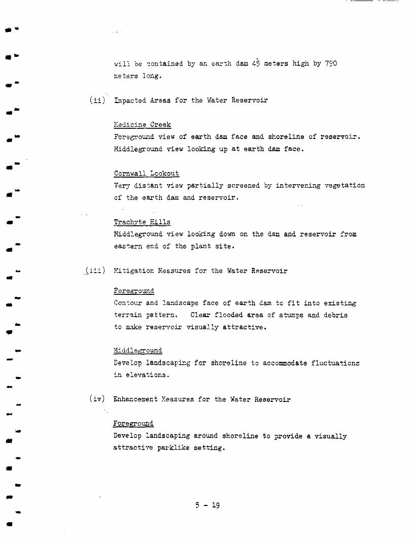
Nedicine Creek Foregrouad view of ea r th dam face and shoreline of reservoir .
iYliddleground view looking up at e a r t h dam face.
Cornwall Lookout_ VerT d i s t a n t v i m par t ia l ly sc reened by intervening vegetation
o f t he ea r th dam and reservoir .
Trachyte Hills Middleground visw looking down on the dam and reservoir from
easCern end of -the p l a n t s i t e .
.. (iii) Plitigation Meestrres f o r the Water Reservoir
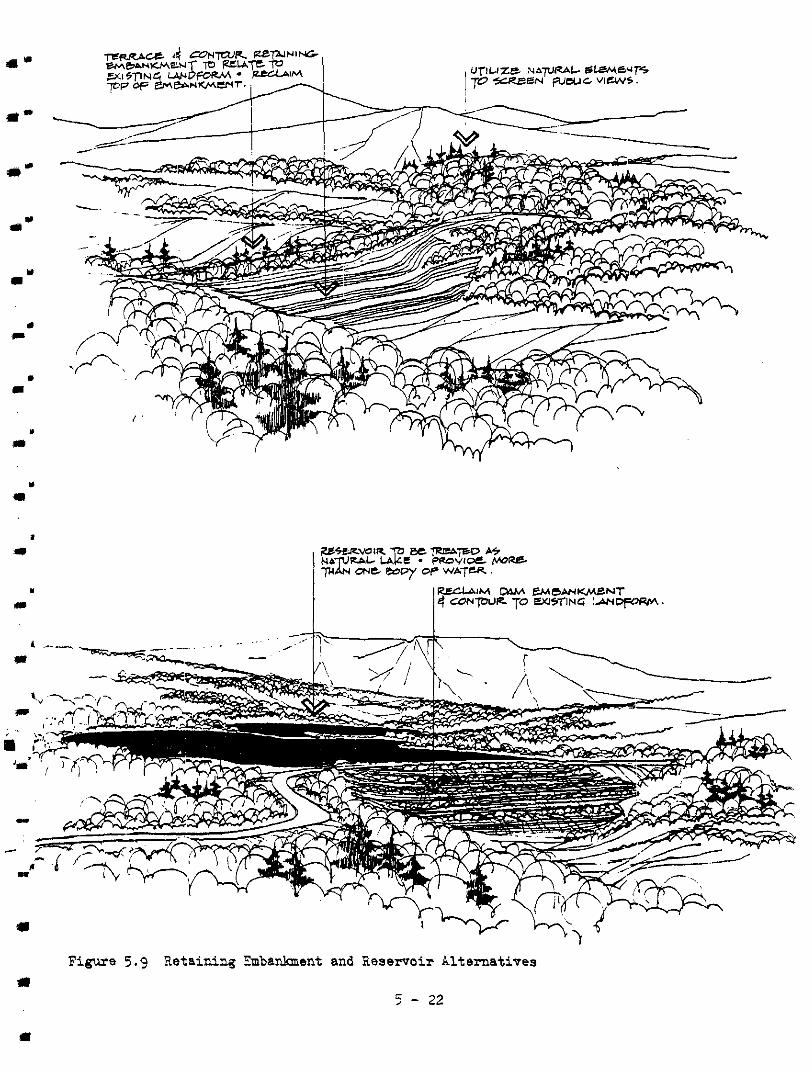
Foreeound Contow and landscape face of earth lam t o f i t i n to ex i s t ing terrain pattern. , Clear f looded area o f s*ps and debris
t o &e reservoir visua:.ly a t t r a c t i v e .
Cdd lenound
Develop landscaying for shorel ine to accommodate f luctuat ions in elevations.
(iv) “dancemert Measures f o r the Water Reservoir
Foreaound Develop landscaping around shoreline to p o v i d e a v isua l ly a t t ract i ’ re parkl ike set t ing.
5 - 19
a-
I"
..-
I
"
. L
. 9 . *I
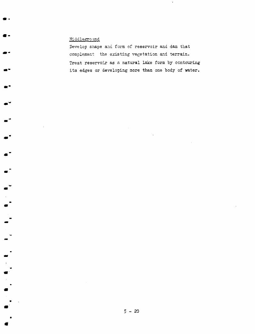
Midd1emo:md
Develop shape and form of reservoi r 2nd dam tha t
complement the existing vecetation acd t e r r a in .
Trea t reservok as a na tura l lake form by contouriag
its edges or delreloping more than one body o f water.
I
. I
Figure 5.9 Retaining Embankment and aeservoir Alternatives e
5 - 22
m-
IL L
I L
I L
m I
I )
c
U
" 1
5.4 ALTFJJIATIVE MEASURE5 FOR :PIT AND RELATdD FACILITIES
(a) OPEN PIT MINE
(i) Physical Characterist ics . o f the Open P i t Nine
The open p i t mine will encompass an area of 470 hectares by the gear 1994 and over 750 hectares by 2021. The p i t
will be excavated ir the form o f benches about 15 meters
high which will accommoda+.e shovels, large dump truoks, and possibly a ilucket-wheel excavator machine. By .the
year 2021 the p:tt will be about 187 meters in depth.
Three conveyors requiring approximately 62 meters for a right-of-way w i l l be used t o transport material out of the pi t .
(ii) Impacted Areas f c r the Open P i t Mine
Uuuer Hat Creek Valley
Foreground viewri a t the north end of this val ley of the
excavation.
Middleground views from edge of excavation and h t o the
open p i t mining operation.
Medicine Creek Vu Middleground and d is tan t views from western edge o f this va l ley in to and across the open p i t .
Hiahwav # 12 Distant oblique view of the hole created by the open p i t
mine.
Trachyte E i l l s
Distant view of the whole open pi t operat ion from weistern
edge of the Trac:hyte Hills.
5 - 23
(iii) Mitigation Measwes for the Open P i t Mine
re
I-.
ForemounC
Develop s t rong ledge definit ion using drainage ditches am5
perimeter road where required.
Middlemound ami Background
De.pending on mining technique, define the ultimate perimeter
at eat-18 stage to provide a s t rong i den t i f i ab le edge to the
open p i t .
Control pcblic access to pit area by developing controlled
viewpoints that provide opportmit ies t o display an orderly
appearance of the mining operatiog.
Mipimize haphazard erection of mintenarce and storage
f a c i l i t i e s i n the open p i t mine.
. .
( i v ) Enhancement Meesures f o r t h e Open P i t Mine
U L
Foremound and Middleground Examine f e a s i b i l i t y of using surface material to c rea te high
berms along south rim of p i t t o p rov i i e a landscaped termin- a t ion f o r the southern part of the Upper Hat Creek Talley
v isua l un i t .
(b) BLENDING FACILITIES A M ) STOmIU'S
d "
(i) Physical Characteristics of the Blending Facilities and Stockpiles
The blending fac: i l i t ies and the s tockpi les o f coa l a re located next to the entrances t c Marble Canyon, Highway #12,
and Upper Hat Creek Valley visual units. Si ted here are the
primary and secocdary mshers , coal preparation area,
U
I
5 - 23

Q r
.*-
a-
m-
blenders, and spreaders f o r stcckpiling. Four large stock- p i l e s of coal 780 meters long by 62 rreters wide and 15 msters
high along wit?. the 50 hectare surface material dump are par t
of the blending faci2i t ies area. The access road t o the plant from Highway #lZ passes through the blending area.
(ii) Impacted Areas f o r the Blending Facil i t ies and Stockpiles
Mmbie Canyon
Furegound view o f t h e f a c i l i t i e s and s tockpi les r e x t t o
southern entrance t o Karble Canyon.
Upper Hat Creek Valley
Foregound view at entrance t o north end of Upper Hat Creek
Valley. Middleground r i i s w across open p i t mine of blending ,area
f a c i l i t i e s .
Medicine Creek V-
Distant oblique view from western end of tkis valley.
11 I
Highway # 1 2
Middlegroun6 vie!w of s tockpi les and b lending fac i l i t i es f r o m highway.
Foreground view from western entrance t o Highway #12! visual unit entrance.
Trachvte Hills Distant view looking down a t t h i s area from western edge of
Trachyte Hills.
(ii.i) Mitigation Measures f o r the Blending Facil i t ies and Stockpiles
Foreground
lltem3f.e access around p i t f a c i l i t i e s should be developed t o
5 - 25
# L
e a.
u
II)
eliminate confLicts between public and operation of
f a c i l i t i e s and t o minimize foregrvmd views through
th i s a r ea . Develop s i t e pl.ans and organize elements t o naximiae
the separation fror, the entrance t o Xar’cle Canyon and
Highway #I 2.
Middledound Examine use of man-made landscape elements such as ester-dons to Houth Meadow s p o i l dam and a lake t o s e p a r a t e p i t f a c i l i t i e s from e c t r m c e t o Marble Canyon.
Background Organize elements i n t o an orderly design by grouping
r e l a t e d f a c i l i t i e s and keeping stockpiles confined in a
well defined ar13a.
(i) Physical Characterist ics of the Hovth Meadow Dump
This s p o i l dump located a t the north end of Upper H a t Creek
Valley will be created by the construction of a re ta in ing embanhent 155 meters high and 1932 meters long. THro re ta in-
ing enbankments would also be required t o prevent slippage
i n t o Marble Canyon. In 1994 the dump would coTer 410 hec- tares; by the year 2021, 618 hectars . The s p o i l material would be sloped a t 1 t o 20 o r 1. t o 10 depending on the com- pos i t i on o f the s p o i l . If the 1 t o 10 slope i s used, the
Medicine Creek dump would n o t be required.
5 - 26
( i j . ) Impacted Areas for the Houth Meadow D u 1 p
Marble Cemon Middleground viewe looking up a t f a c e of re ta in ing embark-
ments from xouthe:m end of the canyon.
Upper Hat Creek V : & l a
Foreground view w: face of r e t a in ing embankment from
northern entrance t o the valley. Oblique middleground visws of embankment and surface of s p o i l dump from northern
sections o f the Upper Hat Creek Valley.
Medicine Creek Va:Lley
Distant view looking down on the re ta ining embankment an2 the spoi l dump f r o m western edge of zliis valley.
Highway # 1 2 Middleground viewe: o f the face of the re ta ining embanbment
from western entrance t o this v isua l unit. Distant views of embankment and s p o i l area f r o m secticsns
of the highway.
Cornwall Lookout Very d is tan t view pa r t i a l ly screened by intervening hills of the surface of the s p o i l area.
Trachyte Hills Distant view 1ooki:ng down on the fu l l ex ten t o f the re ta ining embankment and the spoil area.
( i i i ) M i t i g a t i o n Measure:; f o r the Houth Meadow Dump
Foremcund
Develop landscape grogram f o r sequent ia l rec lamt ion of
5 - n
1 .
-. . 1
.
I
L
re ta in ing embanlment t o complement existing vegetation
and te r ra in pa t te rn .
Design shoreline of s e t t l i n g lagoons to look na tura l and be part of landscape.
Middleaound Design r e t a in ing embankments to b l end i n to ex i s t ing t e r r a in
and be compatib1.e with existing landscape form.
Extend main reta.ining embankment and shape t o define etge
o f p i t f a c i l i t i e s a r e a .
Backkrmmd Develop methods f o r progressive shaping and revegetation of spoi l a rea . Contour and vegetate edges of spoil dump t c f i t in to ex is t ing
landscape.
( i v ) Enhancement Measures f o r the Houth Meadow Dmp
Middleaound and Background
Extend and contour main retaining embanbent to terminate
the open p i t opera’cion and t o enhance the existing entrance
t o Marble Canyon.
(d) MEDICINE CREEX DUMP
(i) Physical Charac : t e r i s t i c s of I ;he Medicine Creek Dump
!The Medicine Creek dmp is loceted at the western edge of this val ley near the north end of the Upper Hat Creek Valley.
A re ta in ing embankment about 187 meters high and 2490 meters
long would be constructed to create the spoil area for the
s tab le mater ia l from the mine. i n 1994 i t would cover 236 hectares ard 490 hectares by 2021.
5 - 28
U'
(ii) Impacted Areas f o r the Medicine Creek Dump
Marble Canyon
Distant oblique riew of face of edmnkm.ent from southern
entrance t o Marble Canyon.
Upper Hat Creek Valley Forepound view looking up at. the face of the re ta in ing
embankment.
Middleground and (distant views of the embadacent and the
s p o i l dump from various p a r t s of the northern half of Upper
Hat Creek Valley.
Meiicine Creek Va:Lley Foreground view looking down 01: the surface of the spoi l
dump.
Trachyte Hills
Midd1egrow.d view:, looking down on the spoi l dump from the southern edge o f .the Trachyte Hills area.
C
(iii.) Mitigation Measures f o r the Medicine Creek hmp
"I
I
r
ry
Foremound
Contour and landscape face, crest , and toe of re ta in ing
embankment i r t o ex is t ing t e r ra in . Develop sequent ia l dumping and reclanat ion methods fol: re-
vegetation and mirlimal v i sua l impact of s p o i l area.
Middlemound and Backmound
Develop progressive clearing programs t o ninimize need. t o c l ea r fu l l extent of spoi l area.
Contour and revegetate spoi l area t o f i t i n t o existiq:
landscape.
5 - 29
Relocate, if possible, t o Iiotth Meadow and maintain existing landscape.
( e ) RAT CREE^ DIVERSION
I L
. - L
I
. U
.,
m
(i) Physical Characterist ics of the Hat Creek Diversion
Included i n the Hat Creek divers ion are the 7.0 la. canal, a 2.2 lan. dischwge conduit, water reservoirs from '7.3 hectares t o over 80 hec tares (a l te rna t ive) , a canal service
road and the access road t o the Upper Bat Creek Valley.
The main canal and road right-of-way vary i n width from 37 t o 62 meters m~cl require 30 hectares o f land.
(ii) Impacted Areas for the Hat Creek Diversion
Upper Hat Creek Valley Foreground views along the northern sections of this1 val ley
of the canal and. i ts roads.
Middleground and, d i s t an t views from acrcss the valley.
Medicine Creek Valleg Middleground and 'd is tan t views looking down a t the canal,
the roads, and the reservoirs .
Trachyte Hills Dlstant views of looking down from the westerr. edge of t h i s
s i t e on the Hat :reek diversion system.
(i1.i) Mitigation Measures f o r the Hat Creek Diversion
Foreground
Design system with a road tha t meets access and semice re- quirements f o minirize the right-of-way required.
Develop landscaping t o blend i n with exis t ing pat tern of
5 - 30
"
U-
a ..
m (.
I *
vegetation. Develop opportuni t ies t o c rea te natural reservoi rs wherever canal intersects the creeks f lowing in to the Upper Hat Creek
Valley.
MiddlekTow-d
Develop shorel ine of reservoi rs t c r e f l ec t ex i s t ing l akes
in the val ley.
Blend cuts and f i l l s i n t o t e r r a i n m-d revegetate t o minimize
their visual impact.
BackrTound
Develop edge of canal t o soften visual impact by blending into the existing landscape.
( i v ) Enhareement Mea,sures for the Hat Creek Diversion
Foremound, Middlemound, Background Relocate existing access road away from apen p i t mine and
p i t f a c i l i t i e s by lirlcing t o plant access road.
Develop a l t e r m . t i v e t o Rat Creek diversion by creat ing tine
larger reservoi:? (80 hectares) with underground piping.
m
1 5 - 3:
m c
I
I"
e-
I
..
5.5 ALTE:RNBTIVE MEASURES FOR LINKAGES
( a ) CONVEYOR
(i) Physical Characterist ics of the Conveyor
The main conveyor is required to t ransport the coal f ron the
blending stockpiles t o the s torage a rea a t the p lan t s i te on .top o f the Trachyte Hills. This conveyor would be approxi-
mately 2500 meters long, would be covered, and would be above
grade. The present line proceeds i n a southeaster1;y direction
t o a point halfway up the hill. It then continues :in a north-
eas te r ly d i rec t ion t o the p lan t s i te .
(ii) Impacted Areas f o r the Conveyor
Marble C m
Distant view looking up at the ccnveyor from the enlzance t o Marble Canyon.
Upper Hat Creek Val ler
Midtleground and, d i s t an t views looking up a t t h e conveyor
f r o m various seotions id the northern p a r t of this valley.
Medicine Creek V a l l e y
Middleground v i e w o f parts of the ccnveyor system from the
western end of Medicine Creek Valley.
Hixhway # 1 2
Distant oblique view l o o H n g up a t s e c t i o n s of the comeyor as i t leaves the blending stockpile area.
Trachyte Hills
Foreground and Middleground views o f sect ions of the conveyor
system.
5 - 33

I'
1.
- . .
I
D I
I
I ?
I -\
. r
1
#
i . - .
1
. L
I ' ~
I
I I
1
(i.ii) Mitigation Measvres f o r the Conveyor
Foreground
Design conveyor system 8s a strong archi tectural design
element that emphasizes the link tetween the blending
fac i i l t i es and the plant. Design structural elements t o r e f l e c t and complement the other p l a n t s t ruc tures .
Middleground and Backvround Alignment of conveyor should be as d i r e c t as p0ssib:l.e
between p l a n t arid blending area t o vist tally strengthen
the linkage between the two.
Design of conveyor should express the high technologv
requirements of the project t o provide a cont ras t to the existing landscape.
( b ) .RCCESS ROAD
(i) Physical Characterist ics of the Access Road
A highway is located t o provide access from Highway #I t o the p l a n t s i t e and t h e p i t f a c i l i t i e s . It f o l l o w s an exist- ing trail from the highway up Ccrnwall Creek, past Cattle and Medicine Creek valleys t o the p lan t s i te . From the plant
s i te i t goes i n a westerly direction down through the blending f a c i l i t i e s a r e a t o Highway #12. The t o t a l length of this road would be 31 kilolreters. Maximum grade 8$ and designed t o 80
kmh. s tandards . Right-of-way f o r this road would be up t o
1OC meters wide and cover about 1CO t o 122 hectares of laud.
(i.i) Impacted Areas for the Access Road
Karble Canyon Distant view of road as i f comes down the Trachyte Hills.
* . 13
5 - 34

I
” 1
u
1
Youer Het Creek V u Foreground view of road. as i t winds through the area around
the blending faci l i t ies .
Middleground and d i s t a n t views o f the road as it comes down
the Trachyte Hills.
Medicine Creek VaLley Foreground and middleground views of r o a l as it appro;nches
and leaves the plar t s i te .
Cattle Valley
Foreground and middleground views of road as i t passes through
Cattle Valley.
Highway # 12
Distant oblique view of small sect ions of road as i t comes down the Trachyte Hills.
Highway # 1
Foreground, middleground, and d i s t an t views of road as; i t climbs up towerds Cattle Valley from Highway # I .
Cornwall Lookout Very distant viewe of partially screened road right-of-way
as i t crosses eastern end of Medicine Creek Valley.
Trachyte Hills Foreground and middleg-round views of road as i t approaches plant f r o m the eas t and the west.
(iii) Mitigation Measures f o r the Access Road
Forearound
Exanine re loca t ion o f road n e a ash dump t o m z e natural
5 - 55
=*
"
1. "
-I '
I
L
c I
1
e
screening and t o minimize this dump's visual izpact .
Examine relocatior. of road t o an alignment east of tihe plant.
Avoid public access through blending area.
Develop main access road as a bypass from Highway #l t o Marble
Canyon with separate service and v i s i t o r access r0ad.s t o plant ,
the open p i t and Upper Hat Creek Valley.
Foremound. Midd.lemound, and Backmound Design road t o conform and respect immediate landform by not
cutting through i t . Reclamation of cut and f i l l areas should begin immediately and
should conform t:o ex is t ing t e r ra in and vegetation pattern.
Locate access mad t o take advantage o f screening zclnes where
views are undesirable.
Retain groups o f screening trees t o sof ten views of cuts o r f i l l s .
( iv) Wancement Meamres f o r the Access Road
Foreg-round, Midd.lemound. and Backmound
Design road ali@unent to take advantage of opening new v i s t a s
o f the natural and man-made elements.
( c ) 500 KV. TRANSMISSIOIT CORRIDOR
(i) Physical Charact:erist ics o f the 500 Kv Transmission Corridor
Two 500 kv. t ransmission c i rcui ts are located in the t rans- mission corridor that l inks Kelly Lake t o the Nicolet substation.
"he existing right-of-way passes near Cattle Valley. A link
from this corriCor would be made to the 9at Creek power plant.
(ii) Impacted k e a s f o r the 500 W Transmission Corridor
Medicine Creek T ' a l l e y
Distant view of small sect ion of the transmission towers.
I 5 - 36
I =
a-
. 1
Cattle Valley
Foreground and middlemound views of the transmission lines
and towers as they pass through this valley.
Highway # 12 Foreground view of corridor as i t crosses Highway #1.2.
Middleground acd d i s t a n t view of corridor and towers from various sections of Highway #I 2.
Cache Creek
Distant view o f towers as they cross Highway #l .
Thompson River
Foreground, middleground, and d i s t an t views of transnission l i n e and towers as they cross this v isua l unit.
HiRhWW # 1 Foreground view of towers and corridor as they cross Highway
#1. Middleground and distm-t views as i t descends f rom Cat t le
Valley and goes through the Thompson River visual unit.
Cornwall Lookout, Very d i s t an t views o f corridor as i t cuts across the Marble Range.
Trachvte Hills Distant views of transmission l i n e , towers and the corridor
a s i t crosses Highway #12 and Cattle Valley.
( i f t i ) Xitigation Measures f o r the 500 W TransEission Corr.idor
Foreground, MiddleGound, and Background
Develop corridor clearing p l a n tha t modulates edges t o b t e c a t e
b
1
* d
5 - 37
a
. I
I
1
, '
il
. L
1
1
crosses over tha highway from the Thompson and goes up
towards Cattlc Valley.
Trachyte Hills
Distant view of corr idor as i t cuts across Medicine Creek
Vd ley .
(i.ii) Mitigation Measures f o r the Water Pipeline Corridor
Foremound, Middleeound, and BackTound
Modulate clearing through heavily treed areas to res,emble exis t ing pat tern, o f vegetation.
Integrate into grassland where cor r idor cu ts through. open
range areas.
Examine use o f access roads a t various points to minimize
visual impact of a continuo- service r o a d which emphasizes l i n e a r i t y of ccrr idor .
Design surge tariks, bocster pumping s t a t i o n s , and clearwell t o complement colour, texture, and form of the natural land-
scaFe .
(.i) Physical Characterist ics o f the Airport
n 1500 meter runway is located about 1.5 kilometers xest o f
Highway #I and 1.0 kilometers south of the new acces:s road t o p l a t s i t e . 'Chis paved runway would be su i t ab le :'or execut ive type jot a i rcraf t as well as other small a i rc raf t .
( i i ) Impacted Areas fo r t he Airport
Bighwav # 1
Distant view of edge of runway er.banhent from Highway #I.
5 - 39

m .
. a
. p.
I
.
. U
(1i.i) Mitisation Measuces f o r the Airport
Foreqound, Middlef-rouxd, ar.d Backflcund
Contour ar.d landscape cut and f i l ls f o r runway t o f i t
ex is t ing t e r ra in pa t te rn .
5 - 40
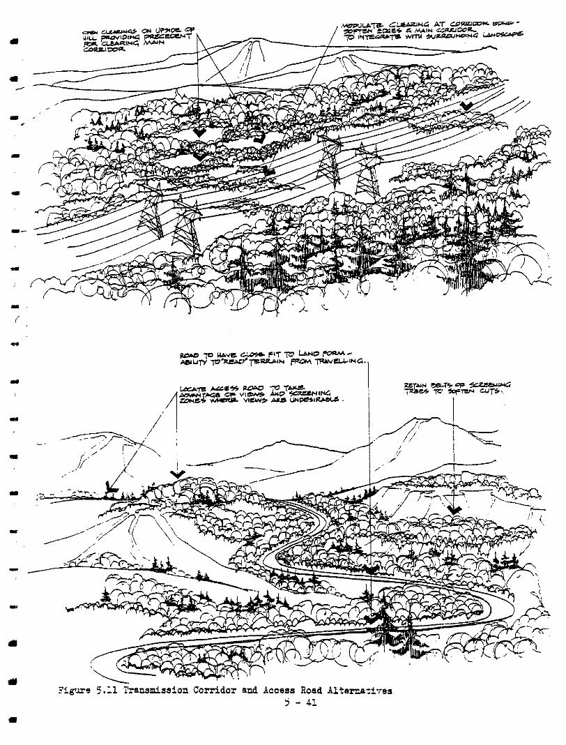
?igurd 5 .I1 I'ransmiaaion Corridor and Access Road Alternati-res -.
5 - 41
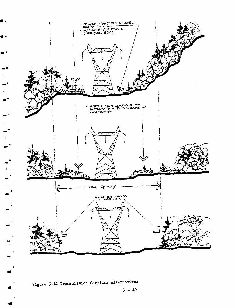
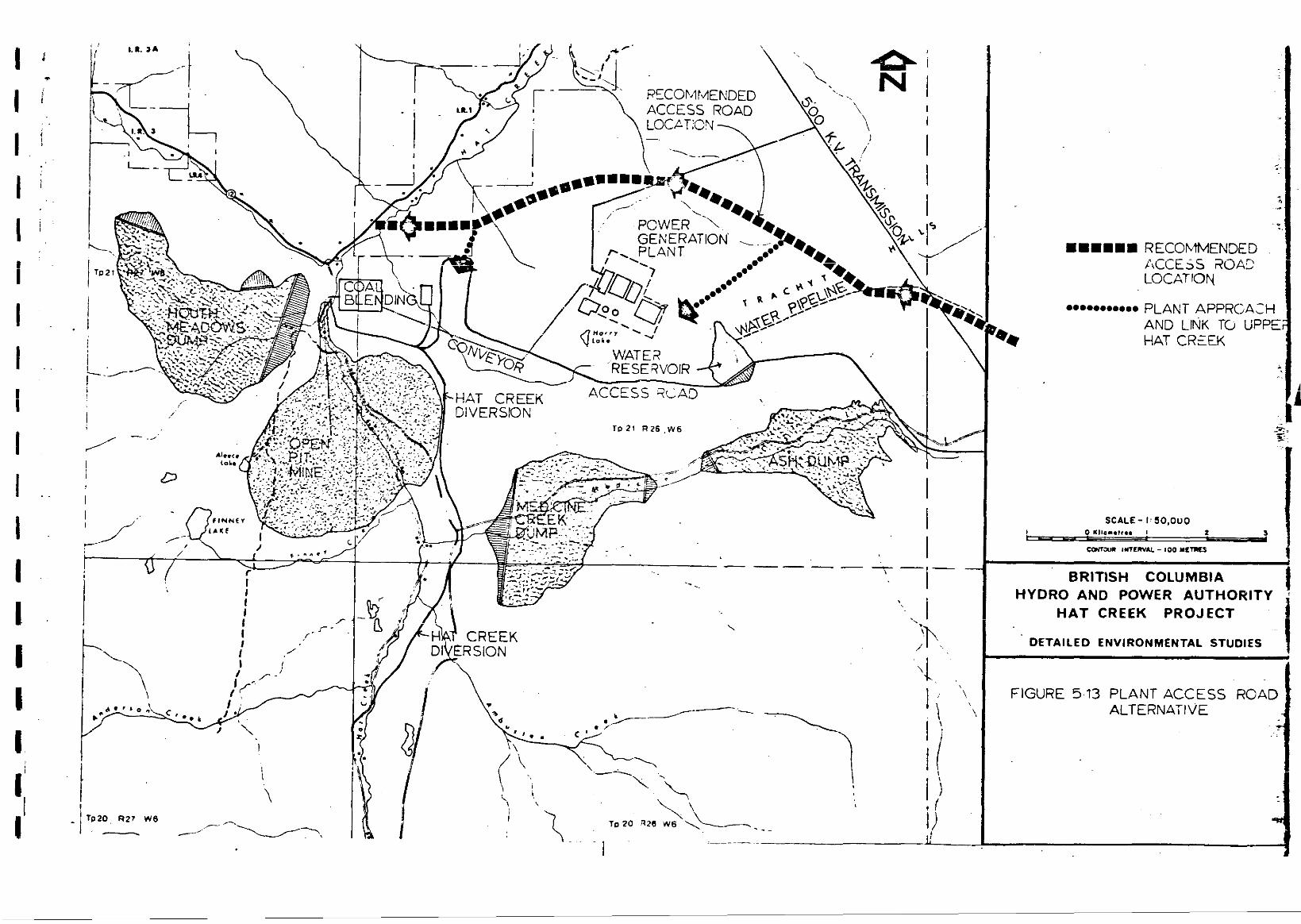
1 . i
i . .
i
i
i
. .
. .
._I
...
.*..*...*.. PLANT APPROACH AND LINK TO UPPE HAT CREEK
BRlTlSH COLUMBIA HYDRO AND POWER AUTHORITY
HAT CREEK PROJECT
~~
DETAILED ENVIRONMENTAL STUDIES
FIGURE 5.13 PLANT ACCESS ROAD ALTERNATIVE
i
II"
I "
II-
5.6 ALTEIWATIVE MEASURES FOR ilATER INTAX3 AND WLBTED FACILITIES
(a) WATER INTAKE
Physical Character is t ics
A water intake structure i s located i n the Thompsos River j u s t above the mouth of the Bonaperte River. This s t ruc ture
i s about 34 meters long , 9 meters wide and 9 meters above
high water.
Inpactet Areas
Thompson River
Foreground, rnicdlegroucd and d i s t a r t views of the intake
s t ruc ture from vnrious parts of this v i sua l a t .
Enhancement Meas.ures
Foremound. Middlemound, and Background Develop intake s.tructure as a rch i t ec tu ra l element that
r e l a t e s t o the form, colour, texture, end l i n e of exis t ing
lacdscape components.
(b) STORAGE AND PUMPING FACILITIES
1 L
I Y
(i) Physical character is t ics
Water from the intake would be pumped t o a 30-meter diameter c l a r i f i e r , then in to a 6-meter diameter cletwwell
before entering the high pressure pumping station. This
s t a t ion would be about 60 meters long, 13 meters wide, and
i3 meters high. 811 th ree s t ruc tures we loca ted :ust south of the mouth of the Bonaparte River.
I W 5 - 44
( i i ) Impacted Areas
Thomosor River Foreground and middleground views of this area next to
the mouth of the Bonaparte River.
( i i i ) M i t i g a t i o n Meanwes
Forenround, Midc.lemound, and Backkround
Develop s t r u c t u e s as arch i tec tura l e lements to ccn izas t
and complement form, co lour , and texture of surrounding
landscape. Develop hndSCagin& t o provide transit ion between s t ruc tures
and existing lacdscepe and t o minimize visual impact; of
s t ructures .
5 - 45 . m

I
m ..I
a .)
I .
- . 1
1)
4.7 ALTERNBTIVE W S FOR COEISTRUCI!ION FACILITIES
(3) P M V CONSTRUCTION C l W
Physical Characterist ics
An area of 12 hectares near the plant s i te would be cleared
t o accomodate the construction camp f o r m a s i m u m of 1000 men. T o t a l l i f e o f the camp would be approximately eight years.
Impacted keas
Medicine Creek F’’ Distant view loclking up a t edge o f construction camp
f a c i l i t i e s .
Trachvte Hills Foreground and middleground views of construction casp
from various areas around p lan t si te.
Mitigation Measures
Forenound, Middleground, and Backmound Ut i l i ze natural contours and vegetation $0 sof ten close-up
view of camp s t ruc tures and to screen middleground and distant views.
Minimize d is rupt ion to natural contours and vegetat ion to
facilitate r ec l ana t ion a f t e r camp s t ruc tu res a r e removed.
(b) MINING CONSTRUCTION CIW
( i ) Phys ica l Charac te r i s t ics
The camp is located just above and eas t of the coal hlending area. It covers a c leared a rea of 6 hectares and woxld accou-
modate up t o 440 men. This camp would a l s o have a l i f e c y c l e
5 - 46 .

.. 1 .
1
. 1
. 1
of approximately eight years.
( i . i ) Impacted k e a s
Marble Canyon Distant view, par t ia l ly sc reened by intervening vegetaticn,
from the entrant'. t o Marble Canyon.
Upper Hat Creek ' V a l l e y
Foreground and middleground views from various p a r t s of the entrance t o Cppe:r Hat Creek Valley.
Trachyte Hills
Distant view lookir,g down on camp from western edge of the
Trachyte Hills.
(ii.i) Mitigation Measures
Foremound, Middlemound, and Backmound Util ize natural 'contours and vegetation t o soften close-up
view of camp s t ruc tures and to screen middleground m d
distant views. Minimize disrupt ion t o natural contours and vegetation
t o f ac i l i t a t e r ec l ama t ion a f t e r camp s t ruc tures a re removed.
. Y
4
5 - 47
The general. measwes for mit igat ion, enhancement o r compensation that have
been proposed will require detai led development during the next phase o f this project ' s development.
The in ten t was t o ident i fy the impact cause and t o develop a course o f act ion
thal could then be implemented LL order t o reduce the sensit ivity o.f an impact.
Ihning the next steps o f design development spec i f ic measures will 'be outlined
f o r each project elenent, based on the general statements i n the ab'sve sections.
The following chapter establishes ?he priorit ies f o r the mitigation, enhance-
ment, o r ccmpensation measures.
5 - 40

5.9 EXISTING AND AFTER CONSTRUC!TION VIEWS
m -
m I
The following sketches, along with the preceeding ones i n this chapter , i l lus-
t r a t e t he visual impact of the various project elements on d i f f e ren t pa r t s o f t h e s i t e . The ir-tent of Fibures 5.14, 5.15 and 5.16 i s f o demonstrate graph-
i c a l l y how the cxirttirg views along Highway # 12 are a f fec ted by the project
elements. 'These skntclros art+ ~11.1 taken from Highway # 12 because of the
s ign i f icant number of po ten t ia l t rave l le rs a long this route as opposied to
others i n t:he study area.
Figure 5.14 i l l u s t r a t e s t h e i n i t i a l view o f the generation plant and. s tack
that will be seen by people as they drive westward along Highway # 1.2 towards
Marble Canym. Figure 5.15 i s a before and a f t e r view along the same route
but closer t o Marble Canyon. Figure 5.16 i l l u s t r a t e s t h e view t o the south-
east that people will see from the eastern entrance t o Marble Canyor..
5 - 49
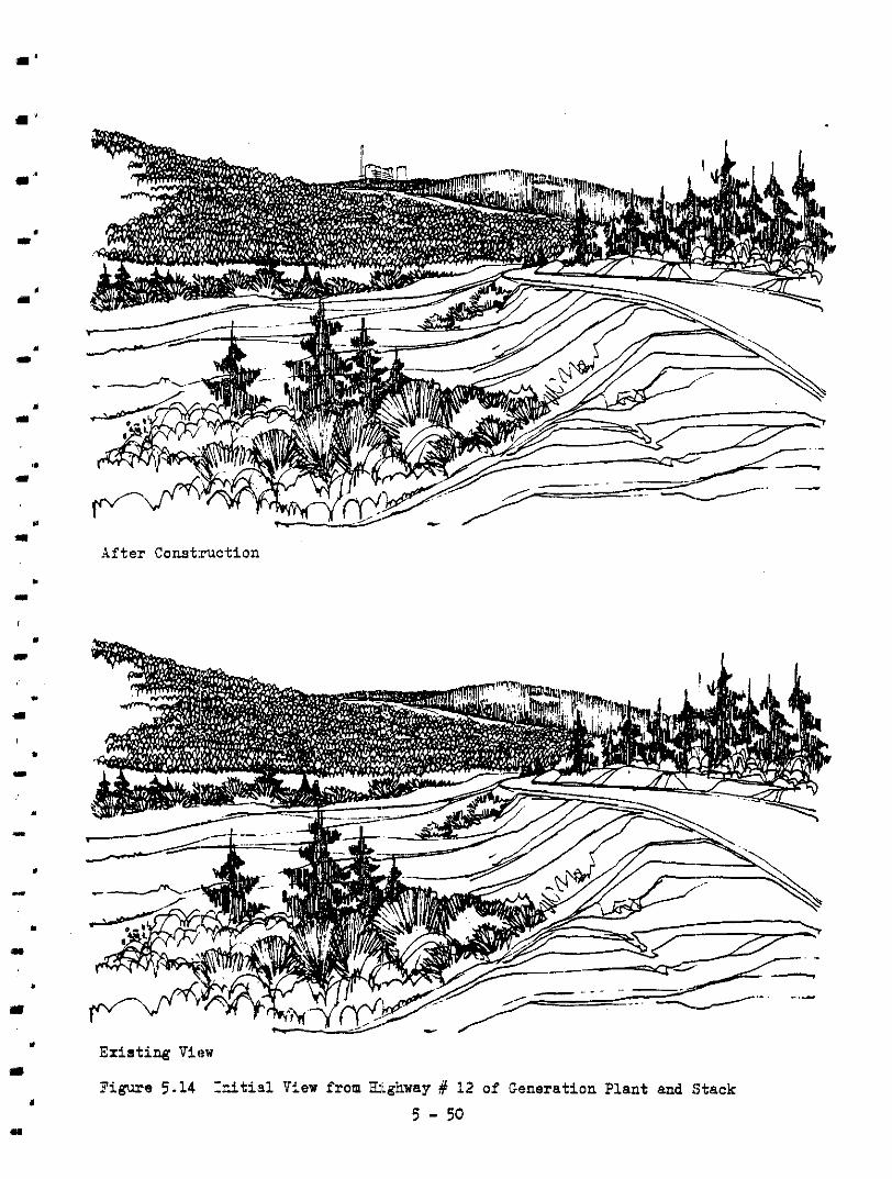
. m
Y
m
. 1
*
m
" II
I
II
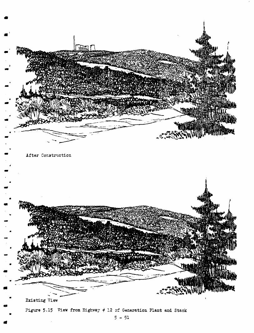
. I After Corstnlction
. .I
. I
. Zxis t i rg Vievr
3 g u - e 5.15 View from Eighuaj- ?.2 0;' Generation Plant and Stack u
u 5 - 51
I

m ..
m
After Construction
Existing View
Figure 5.16 View from Eastern Entrancs to Xar5le Canyon of Generation plant,
5 - F2 Cooling Towers, ar.d Conveyor.

I
m
6.0 PRIOR1T::ES A h T RECOMMENDATIONS
6 . 1 PRIORITY DETERMINANTS
I n this section, guidelines are established for determining the p r i o r i t i e s f o r
a l t e rna t ive measures t o minimize v isua l impact of project elements. They a r e
based primarily on the ex is t ing v i sua l qua l i ty , upon the qua l i t y of .the impact
caused by th.e project element, and on the viewing distance between the observer
and the project element.
Table 6.1 svmmarizes the exis t ing qual i ty of the visual uni ts and the visual qua l i t y o f the impact caused by a specific project element. Each v i sua l unit was l is ted according to i t s leve:. of v i sua l qua l i t y and each project element
according t o i t s impact s ignif icance and appropriate viewing distance. Two v isua l un i t s , Langley and Oregon Jack, have been omitted since they were not
visual ly affected by any of the project elements.
The h ighes t p r io r i ty was given t o foreground and middleground mitigaYon measures
for project elements with extreme and high visual impacts that affected visual
units having outstanding or high visual qual i ty . Foreground and middleground views were important factors sinae they indicate points a t which project elements b e e n t o dominate and d is rupt the ex is t ing v i sua l qua l i ty . Dis tan t or back-
ground views were given lower pr ior i t ies s ince they would benefi t from the miti- gat ion measures affecting middlecound and foreground views. Table 131.3 lists
the order f o r es tabl ishing mit igsr t ion pr ior i t ies based on a project element’s visual impact and a v isua l unit’s visual qual i ty .
7
Viewer chara.cterist ics such as the number of visual contacts by res idents and
t rans ien ts with project elements,. the context within which visual contact was
made, acd the aes the t ic impact each visual contact had on the observer were also taken into consideration. iiowever, the degree of influence these fac tors
6 - 1

1.
-1. I.
had o n e s t ab l i sh ing p r io r i t i e s tias l imi ted due t o , t h e d i f f i c u l t y i n obteining 'data on the number a d type of potential viewers and to the
lack o f conclusive methods for determining a fac tor which indicated the
d i f f e rence i n t he i n t ens i ty of a visual contact between the res ident popula-
t ion and t.he t rans ien t one. This i ssue was resolved when i t became apparent
tha t the loca t ion of the maximum number of visual contacts and t h e c r i t i c a l viewsheds coincided with the areas mast sens i t ive t o the o ther p r ior i ty
determinants.
6 - 2
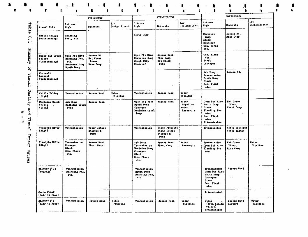
rdrrrt .
--"-- B l u d l W P.C.. .to.
I
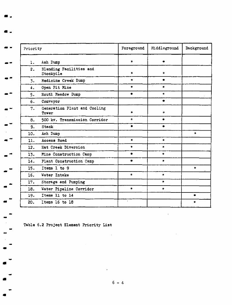
" I Foreground I Middleground I Background I
I-
* Blend.ing F a c i l i t i e s and StockTile * * Medic:ine Creek Dump * Open P i t Mine
* Houth. Meadow Dump
* *
" 7 . ' Generation Plant and Cooling Tower
* 5 0 0 br. Transmission Corridor
* *
10. Ash Ilump
11. Access Road * * 12. Hat Creek Diversion
* *
Mine Construction Camp * Plant: Construction Camp
*
I II
I
I
1 15. Items 1 t o 9 I I I * I Water Intake
Storage and Pumping
* *
* * 18. Water Pipeline Corr idor
*
I 19. Items! 11 to 14 I I I I L 20. Itemrl 16 t o 18
Table 6.2 Project Element Priorit:g List
a
1 II
6 . 2 PRIORITIES
I
1
Table B 1 . l and B1.2 l i s t ed t he p:?oject elements and t h e i r impact significance.
In Table B 1 . l the individual sc01:es of the four assessors were recorded under the form and character of each project element 's visual impact on a visual unit. The average scores of the impacted v isua l units were used t o determine the
relat ive rank o f the impact.
The ash dump near the generation plant caused the most significant visual impact.
The next significant impacts were caused by elements associated with the blending
f ac i l i t i e s , t he gene ra t ion p l an t , and the two linkages, the 500 kir. .:ransmission
l i n e and the main coal conveyor.
Both the number of significant impacts caused by the group of b lending fac i l i t i es
and the open p i t mine elements arid the qua l i ty o f the Marble Canyon, Upper Hat
Creek and Highway # 12 v isua l un i t s made th i s a rea the h ighes t p r ior i ty f o r the
implementation of mitigation measures. The other highly vis ible and s igni f icant
impact was caused by the group of elements surrounding the generation plant and
i t s r e l a t e d f a c i l i t i e s . Its impact was l imited t o the Medicine Creek Valley
v isua l unit which was also ranked with a high visual quali ty.
Significant visual impacts were caused by the linkage elements such (1s the conveyor, the transmission corridor, and the access road. The l inear qua l i ty o f these elements gave them h igh v i s ib i l i t y and p r i o r i t i e s f o r implementing
mitigation measures.
Thus t he p r io r i t i e s f o r implementing mitigation measures are:
( a ) f o r the p i t and r e l a t e d f a c i l i t i e s
(b) f o r the p lan t and r e l a t e d f a c i l i t i e s
( c ) f o r the l inkages: t ranmission corr idor , the conveyor, and the access
road.
6 - 5
6.3 RECOMJIENDATIONS
"
I l r
I l "
1 I
a .
?:e f'cllowing recommendations were based on the p r ior i t ies es tab l i shed above
and upon the alternative measues proposed i n Chapter 5.3. Although accurate
c:osI;s of the proposed measures are not available, the recom.endations do repre-
sen t the measures that could be technically developed within a given budget.
(E) ]?it and Related Faci l i t ies
T!w physical character is t ics of the open p i t mine, blending faci l i t ies , s tock- p i l e s , and dump, and the i r loca t ion i n a v isua l ly sens i t ive a rea c rea te the
need t o vi:wally screen the project elements from foreground and middleground
views; t o minimize o r eliminate public access t o this area; and t o mininize
-he v isua l impact of man-made landforms. The following recommenda,tions are
f o r the p i t and r e l a t e d f a c i l i t i e s :
=.
( i ) Develop and organize the plan of the blending area t o maximize physical and visual separat ion between i t and
the entrances t o Marble Canyon and Highway #l2 .
(ii) Des-Lgn berms and re ta in ing embankments t o complement the
existing landscape through sequential revegetation and
shaping of the man-made forms.
(iii) Relocate the access road that goes though the blending area to elimirlate conflict between public and service
vehicles.
( i v ) Use embmhents c r berms t o terminate the nor th and south ends o f the open p i t mine and r e l a t e d f a c i l i t i e s and t o enhance the entrance t o Marble Canyon.
(v) Develop a s t rong ident i f iab le edge t o t h e open p i t mine with a drabage d.i tch and/or periiceter road.
. m
. I
6 - 6
a -
. ..
. I
L 1
. 3
1
I
I
I
. I
. 1
. a
( v i ) Integrate the Hat Creek diversion canal i r t o the 1md-
scape by c rea t ing reservoi rs for creeks flowing into
the canal.
(b) I?lant and Related Faci l i t ies
The areas :in and around the generation plant, the stack, and the cooling towers represent a concentration o f man-made s t ruc tures and forms tha t pro-
vides the opportunity t o develop a highly technical environment which
re f lec ts the func t ion of the component,s and contrasts with the natural en-
vironment. The r e l a t ed f ac i l i t i e s such as the water reservoir and ash
dump a r e separated from the plant and are t reated as elements that blend
into the existinc landscape. The following are the recommendations that
would accornplish these two objectives:
Develop visual screens with exis t ing vegetat ion and
man-made berms t o control view of the ash dump.
Develop a systen for progressively revegetatine; the ash
dump and reduciag size by creating other dumping amas
in o rder t o reduce the visual impact of one large dump.
Relocate the access road t o a new alignment t o reduae the visual contact with the ash dump.
Use a l l generation p l a n t elenents t o create a 'highkr
technical environment that provides contrast and var ie ty to the natural :Landscape.
Develop a circulat ion pat tern, massing o f s t ruc tures , and
landscaping t o or ient users and visitors in this high
technology e n ~ o n m e n t .
Develop the water reservoir into a visually attract:.ve
amenity around ':he p l a n t s i t e .
6 - 7
1
1
a
(vij.) Emphasize the fsrms of conveyor, transmission take-off,
s tack, and ash transport system to complenent the scale
of the plant el'sments.
The three olajor linkage element,s that cause the greatest visual impact a re
the transmission corridor, the main coal conveyor, and the access road. The
physical character is t ic o f the 'coal conveyor i s used t o emphasize the man- made l i nk between the mine and the plant. The measures f o r the transmission
corr idor and the access road art3 directed ?:ovards the need t o achieve a
closer harmony between these two l i nea r forms and the natural landscape.
(:i) Emphasize form ,of conveyor t o create a st rong visual
link between mine and the plant and t o contrast with
natural landf orlns . (ii) Modulate edges 'of transmission corridor to integrate with
ex is t ing pa t te rn of open and treed areas.
(iii) Select alignments f o r transmission corridor and the access road t h a t u t i l i z e n a t u r a l topography t o minimize l i n e a r i t y
and exposure.
(iv) Examine relocat ion of access road t o an area east o f plant
f a c i l i t i e s in o:cder t o minimize publ ic t raff ic through
blending facil i- t ies area.
(:v) Design road a l i m e n t t o minimize cut and f i l l and .to take
advantage of new vistas of natural and man-made elements.
I 6 - 8

6.4 CONCLUSIONS
Many mitiga.tion measures were proposed in Chapter 5 . 3 . They represent ideas and concept:s which may o r may not be achievable viithin the technical and economic constraints of this project. These measures should, however, be tak:en into consideration during each stage of this project's development in ord.er to min- imize wherever possible its potential visual impact. Each corrective measure that is takton will ultimately contribute to the total mitigation prccess.
There is a justifiable need to implement the recommendations of this: study because of .the many outstanding visual qualities in the study area. Although individually each visual unit has its own visual character it is the total impact of a l l the visual units that gives the study area its visual quality and empha- sizes the med to minimize the impact of a project of this magnitude,. The mea- sures that :lave been recommended will require further development and should be co-ordinated with other mitigation measures during the next phase of the project's development.
I .
6 - 9
a U

APPENDICES
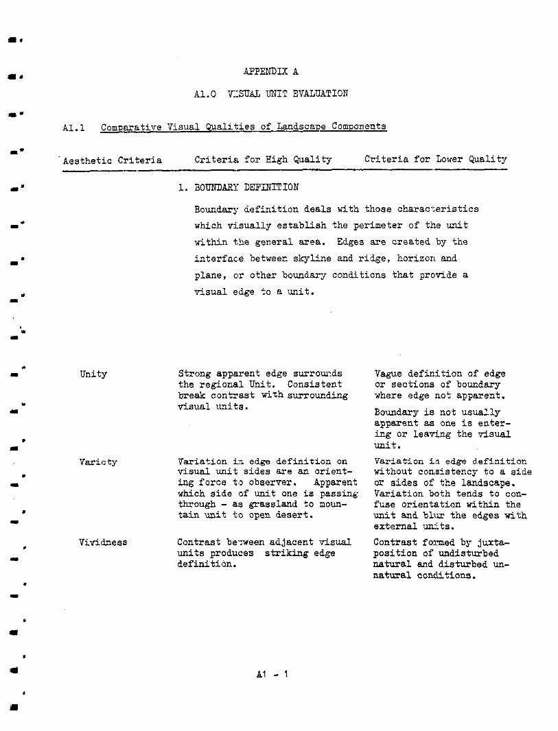
I. APPENDIX A
A1.O VISUAL UNIT EVALUATION
A l . l Camparative Visual Qualities of Landscape Components
m'
. -
. I
. ..
I c
I
I
. I
'Aes the t i c Cr i t e r i a Cr i t e r i a f o r High Qual i ty Cr i te r ia f o r Lower m a l i t y - 1. BOUNDAFX D E F I N I T I O N
Bounday definit ion deals bt th those charac te r i s t ics which visual ly es tabl ish the per imeter of the unit within +,he general area. Edges are created by the
i n t e r f m e between skyline and ridge, horizon and
plane, cir other boundary conditions that provide a
visual edge t o a uni t .
Unity
Variety I
I
. "
Strong apparent edge su r rou lds
break contrast with surrounding the regional U n i t . Consistent
visual units.
Variation i n edge def in i t ion on visua l un i t s ides a re an u r ien t - ing force tO observer. Apparent which side (of unit one is passing through - a:3 grassland t o moun- t a i n u n i t to open deser t .
Vividness units produces striking edge Contrast be.xeen adjacent visual
def in i t iun .
Vague def in i t ion of edge o r sect ions of boundary where edge not apparent.
Boundary is not usually apparent as one i s enter- ing o r leaving the visual unit.
without con:sistencg t o a s ide Variation i n edge d .e f in i t ion
Variation both tends t o con- OT s ides o f the landscape.
unit and blvr the edges with fuse or ientat ion within the
external units. Contrast fomed by ju ta - pos i t ion o f undisturbed natural and disturbed un- natural conditions.
I
I AI - 1
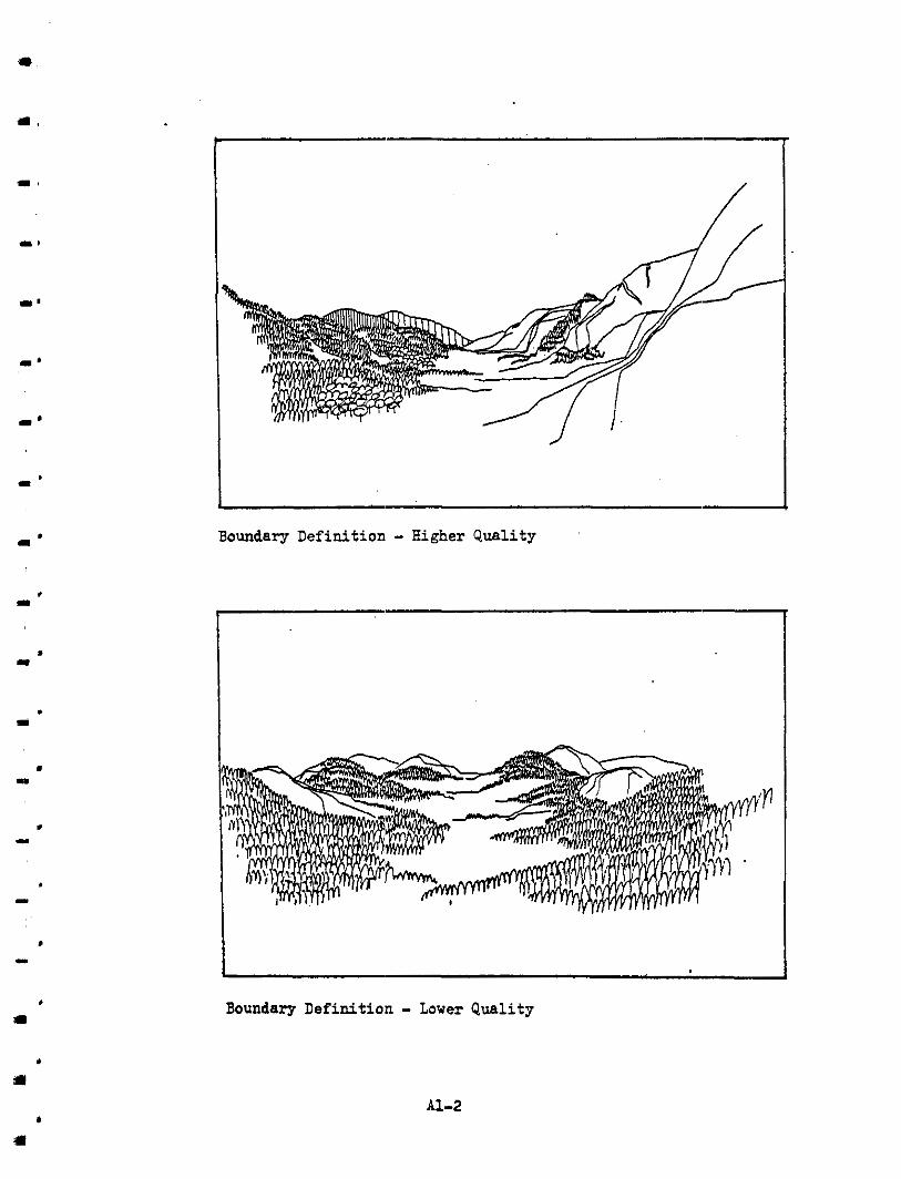
3
1 Boundary Def in i t i on - Lower Q u a l i t y
A1-2
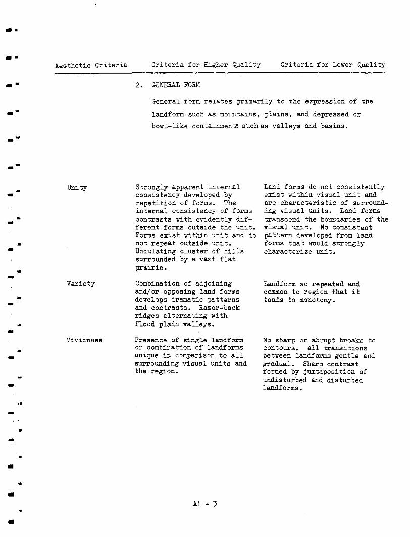
"
1 1
m Y
Aesthet ic Cri ter ia Cri ter ia f o r Higher Qua l i ty Cr i t e r i a : for Lower Quality
Unity
General form relates pr imari ly t o the expression of the
landform such a s mountains, plains, and depressed o r bowl-Like containments suchas val leys and basins.
Strongly apparent internal
r epe t i t i on of forms. The consis temy developed by
internal oonsistency o f forms contrasts with evidently dif-
Forms exis,t within unit and do fe ren t forms outside the unit.
not repeat outside unit. Undulating cluster o f hills surrounded by a v a s t f l a t p ra i r i e .
Land forms do not consis tent ly exis t wi thin YisuaL unit and are charac te r i s t ic of surround- i r g v i s u a l uni.ts. Land forms transcend the boundaries o f the v isua l unit. No consistent pa t te rn developed from land forms t ha t would s t rongly character ize uni t .
Variepr Combination o f adjoining and/or opposing land forms
Landform so repeated and
develops dramatic pat terns common t o region tha t i t
and contrasts . Razor-back tends t o monotony.
r idges a l ternat ing with flood p l a i n valleys.
Vividness Presence o:f single landform o r combir-ation of landforms
No sharp or abrupt breaks t o contours, a l l t r a n s i t i o n s
unique i n 'comparison t o a l l surrounding visual units and gradual. Shar:? contrast
between 1andfo:ms gent le and
the region. formed by juxtaposit ion o f undisturbed and disturbed landf arms.
" a
A1 - ?
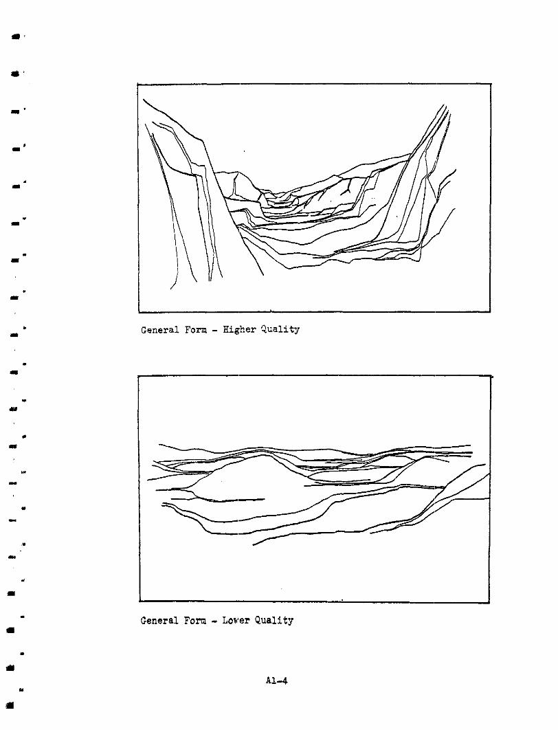
. 1
I
. m
m .
I .
. II
General Form - Higher Qual i ty
General Forn - Lower Quality
. *
" I
A1-4
. I
e
w
.. m
Aesthe t ic Cr i te r ia Cr i te r ia f o r i i igher Quality Criteria fur Lower Qual i ty -
Unity
3 . TERRAIN PATTFLW
Terrain patterr. emerges through repetition of form-shape-
czlour-texture variations. It can vary frcmm sof t undulat ing
hills t o nountainous terrain.
Pa r t i cu la r t e r r a in pa t t e rn
v isua l unit and distinguishes strongly ch,aracterizes the
it from surrounding visual unit.
Terrain pattern consistently associated with presence of a water pattern.
Varie tg Pattern developed by t e r r a i n i n v isua l un i t cont ras t s with the larger region. Unique t o wider geographic area. Landforms composing pa t te rn i n h i g h r e l i e f , composed o f
Vivid landforms such as Xghly dissected topography.
buttes, pinnacles, canyons, steep slopes -- compose the te r ra in pa t te rns .
Vividness dominant and sub-dominant Strong contrast developed by
f ined by vegetational con-, cover. Water presence de-
basts. Vegetation type evidently associated with
mutually reinforce each par t icu lar land form and
other's presence.
No s ing le t e r r a in pa t t e rn dominates or charec'erizes the visual uni t . Terrain pat tern extends beyond u n i t , com-on t o larger region.
The appearance of water i s evidently ir-cidental to the combination o f land forms. Reservoirs i n deserf conditions.
Pat tern developed by t e r r a i n Taguely apparent or not a t a l l evident. Vimal unit appears t o consis t of randomly associ- ated landforms -- no consistent repe t i t ions o r overal l composi- t i o n a l re la t ionship among l a d - forms. Low, inconspicuous land- forms compose t e r r a ix pa t t em.
V i v i d contrasts ieveloped by undisturbed natural conditiors adjacent t o disturbed condi- t ions. Water presence obscured by vegetation - no r i p a r i a n contrast . Vegetational p,attera not strongly r e l a t ed t o lanf .form types. Sage cover on slopes and valley f loor.
*
I
Y
A1 - 5
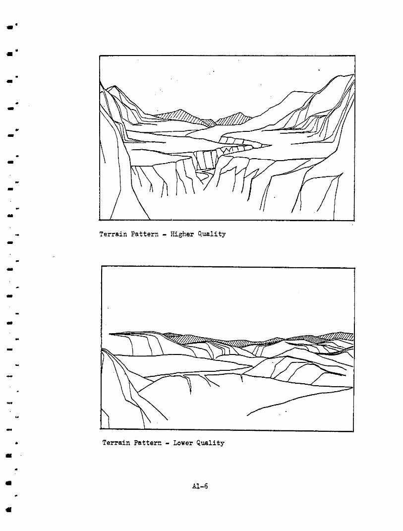
. w
I
" Terrain Pattern - IIigher Quelity
AI.-6
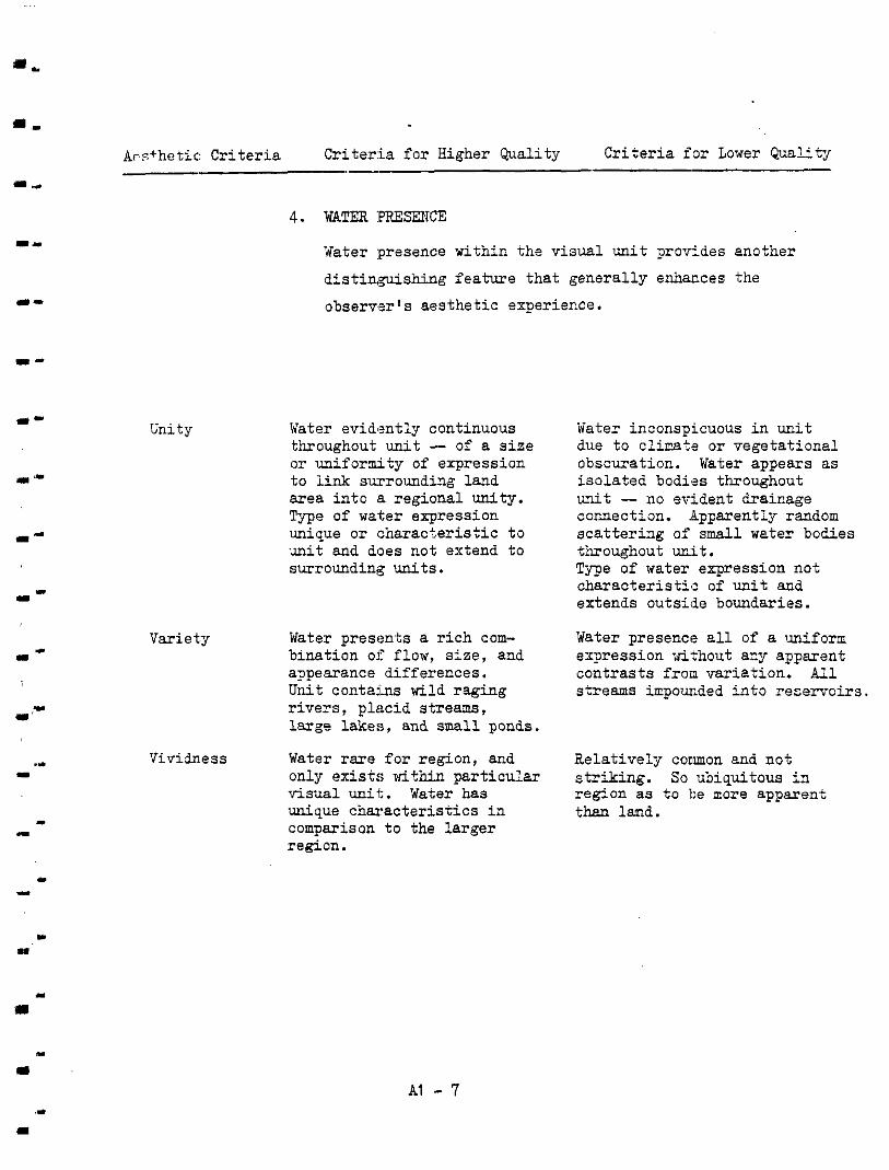
Arsthet ic : Cri ter ia Cri ter . ia for Higher Quality C r i t e r i a f o r Lower Quality .-
a r
"
1-
*-
l"=
"
I
" .L
.I ..
Unity
4. WATER :PRESENCE
?later :presence within the visual unit provides another
distinguishing f ea tu re that general ly enhances the
observer 's aesthetic experience.
Water evidently continuous
o r uniformity of expression throughout unit -- of a s i z e
a rea i n to a regional uni ty . t o link srrrrounding land
Type of water expression unique o r I:harac+eristic to un i t and does not extend to surrounding units.
Variety Water presen-ts a r i c h com- binat ion o f flow, size, and appearance differences.
r ivers , p lacid s t reams, U n i t contains wild raging
large lakes , and small ponds.
Vividness Water ra re for reg ion , and
visual uni t . Water has only exis ts within pa r t i cu la r
unique c h a r a c t e r i s t i c s i n comparison to the l a rger region.
Water inconspicuous i n u n i t due t o climb o r vegetat ional obscuration. Water appears as isolated bodi'as throughout unit - no erident drainage connection. Apparently random sca t t e r ing of small water bodies
Type of water expression not thoughout wit.
cha rac t e r i s t i a of unit and extends outside boundaries.
Water presence a l l o f a uniform expression without a=y apparent cont ras t s f r o m var ia t ion. A l l streams impounded in to r e se rvo i r s .
Relat ively common and n o t
region as t o be more apparent striking. So ubiquitous i n
than land.
AI - 7
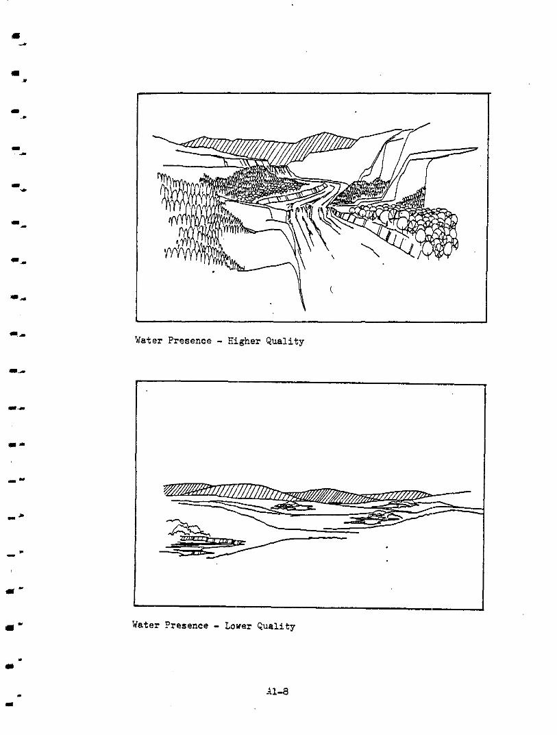
"
r 1
"
m "
1
Water Presence - Higher Quality
L
Water Presence - Lower Quality
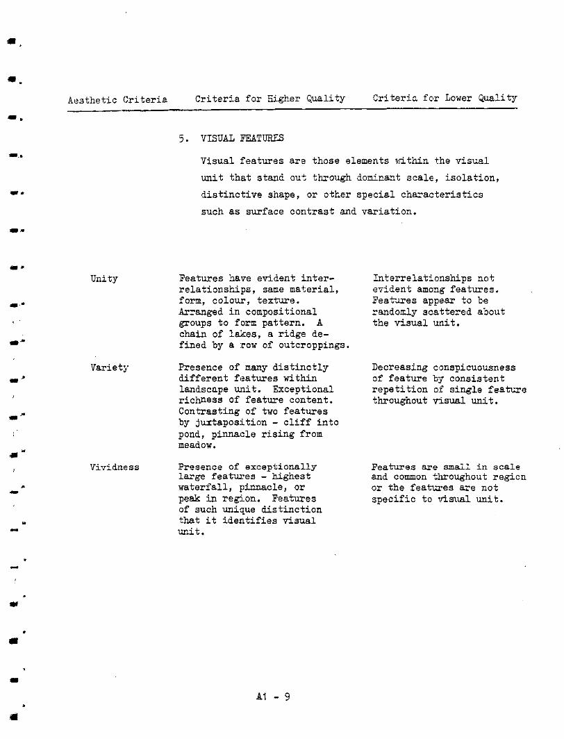
I'
I'
Aesthe t ic Cr i te r ia Cr i te r ia f o r Higher Quality C r i t e r i a f o r Lower Quality
5 . VISUAL FEATURES
Visual features are those elements ?<thin the visual
unit that stand out through doninant scale, isolation,
dist inctive shape, o r o t te r spec ia l charac te r i s t ics
such as surface contrast and var ia t ion.
Unity Features have evident inter- re la t ionships , same material , form, colour, texture. Arranged i n compositional groups t o form pattern. A
f ined by a :row of outcroppings. chain of lakes , a ridge de-
Variety Presence of many d i s t i n c t l y d i f fe ren t fea tures within landscape unit. Exceptional r ichness of feature content. Contrasting o f two fea tures by juxtaposit ion - c l i f f i n t o pond, pinnacle r is ing from meadow.
Vividness Presence of exceptionally
waterfall , pinnacle, o r large features - highest
peak in region. Features o f such unique d i s t inc t ion that i t iden t i f i e s v i sua l unit.
Interrelat ionships not evident among features . Features appear t o be randomly scattered about the v i sua l un i t .
Decreasing conspicuousness
r epe t i t i on o f s ingle feature o f fea ture kg consistent
throughout visual unit.
Features are small i n scale and common throughout region o r t he f ea twes a r e no t spec i f ic t o visual unit.
Y
AI - 9
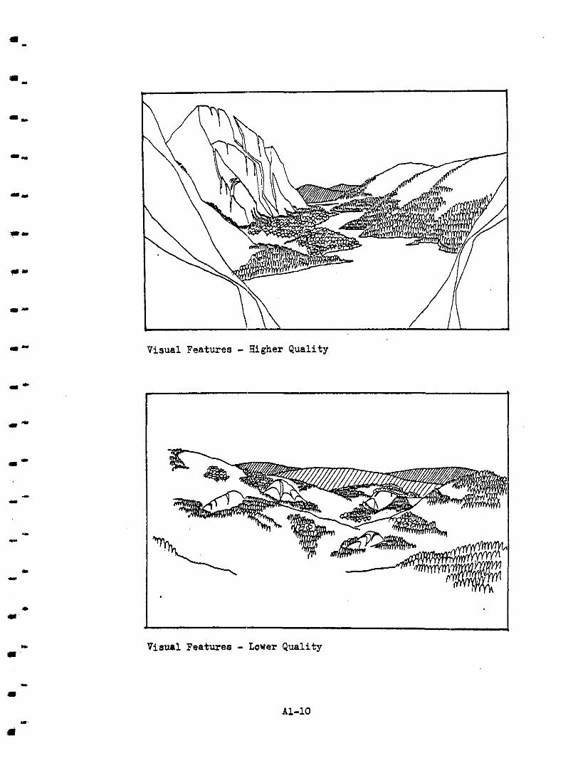
I'
I' I.,
m L
Visual Features - agher Quality
I Visual Features - Lower Quality
81-10
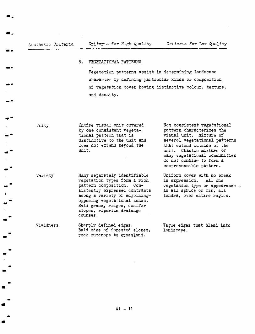
.. a.
&X; t he t i c Cr i t e r i a Cr i t e r i a fo r High Qua l i ty Cr i t e r i a f o r Low Quality u.
U r . i t y
1-
m-
I m
Variety
w L
U ...
I Y
6. E?,GETBTIONAL FQTTEPJS
Vegetation patterns assist in determining landscape
character by def ining par t icular kinds o r composition
of vegetation cover having distinctive colou:, texture,
and density.
Ent i re visual unit covered by one consistent vegeta- t iona l pa t te rn that i s d i s t inc t ive to the unit and does not extend beyond the unit.
Nany separa te ly ident i f iab le vegetation types f o r m a r i c h pattern composition. Con- s is tent ly expressed contrasts among a var ie ty of adjoining-
Bald grassy r idges, conifer opposing vegetational zones.
courses. slopes, riparian drainage
Vividness Sharply defined edges. Bald edge of forested slopes, rock outcrops t o grassland.
Non consistent vegetational pattern charac-terizes the v isua l unit. Ifixture of
that extend outside of the several vegetational pat terns
unit. Chaotic mixture of many vegetatio:nal communities do not conbine to form a comprehensible pattern.
Uniform cover with no break in espression. All one vegetation type or appearance - as a l l spruce o r f i r ; a l l tundra, over entire region.
Vague edges that blend i n t o landscape.
AI - 11
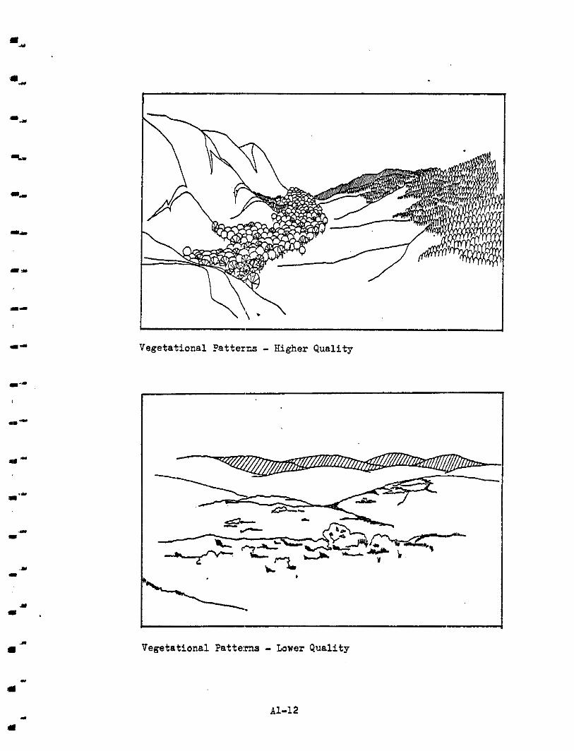
1-
I-
"- Vegetational Datterns - Higher Quality
as-
.. .I
Vegetational Patterns - Lower Quality
AI.-12
Acqitet ic Cri . ter ia Cri ter ia f o r High Qual i ty Cr i te r ia f o r LOW Quality
Cul tural and land use patterns indicate the presence
of hman occupation as characterized by f i e l d crops,
pastures, grazing areas, roads, and other man-made
elements. The form, texture , scale , and colcsur o f the man-nlade changes can enhance o r degrade tihe qua l i ty
of the visual experience.
Unity
Variety
v isua l un i t that does not Consistent pattern within
Valley i n crop pat tern extend t o larger region.
forest cover. Development surrounded b~ continuous
pat terns re inforce natural pat terns . Highways paral-
fences following contour leling drainage courses,
l i nes .
Increase the richness of var ia t ion i n natural pat terns . Plant ing of hedgerows and f ie ld borders on f la t p la ins ; b reaking
with openings of meadows. of continuous forest co-rer
Vividress man-made features. Provides Development of strikirg
s t rong contrast t o natural sweep of land or water.
AI - 13
Development has no apparent pa t te rn and appears t o
Pat tern that evident ly con- sprawl across Landscape.
f l i c t s with natural pat tern. Highway zigza&ng across drainage pattern.
Development has evidently
vera i ty by imposing a decreased the natural di-
formity. Gr id s t r e e t and s t ructured pat tern of con-
u t i l i t y layout. Removal of indigenous vegetation.
Devebprnent o f fea tures tha t degrade the swrounding land-
logging scars, dumps, u t i l i t y scape. Industrial operations,
g r ids , e tc .
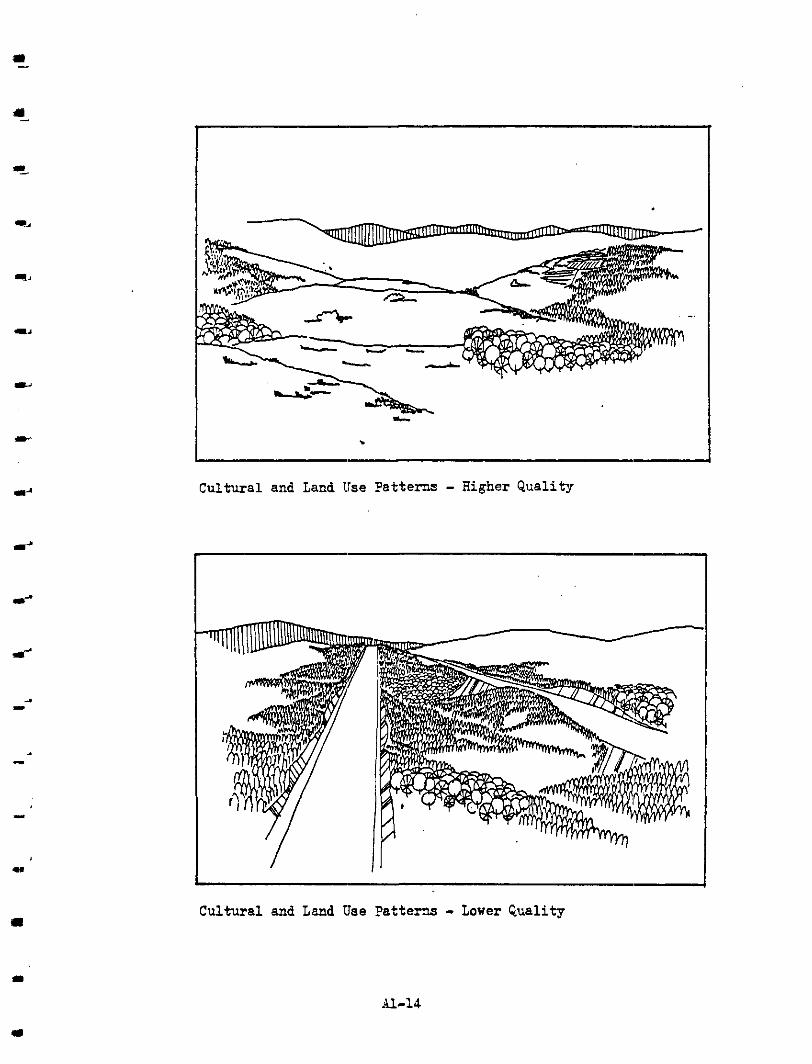
I
.
a!!
4
c1
Cultural and Land Use Patterns - Higher Qual i ty
I
Cultural and Land Use ?a t tens - Lower Quali ty

*
I
"
I
I '
..
81.2 VISUA;; UNIT EVALUATION
For each v i sua l un i t an assessment of the landscape components was mate usirlg the comparative visual qualities described in 81.1 . The numericel
ranking o f the three assessors (Table A 1-1) was then normalized t o deter-
mine the re la t ive rankings o f 'the visual units according t o the norn.alized
numerical values.
The normaliaed score was obtained by assigning t o each assessor's highest
score a value of 7, and a value of 1 t o the lowest score. All values be-
tween the highest and lowest were dis t r ibcted proport ionately and assigned
values betwl?en 1 and 7. This normalized numerical ranking indicated the
assessorls :relative ranking o f the visual units t o a s e t of common k'ase
values (Table A 1-2). The sum of the t h e e a s s e s s o r s ' v a l u e s f o r unity,
var ie ty , and vividness was then total led t o determine the relative ranking
o f each v i s a 1 u n i t t o each other (see Table A 1-3).
The relativq? ranking of the visual units was then grouped i n t o four l eve ls of visual TLality. In the highest level were those visual units having
outstanding o r unique visual qua.l i t ies. They included Marble Canyon.,
Langley, Orssgon Jack and Upper R:at Creek Valley. In the next level were those with 'high o r above average visual qual i ty and included Cattle Vdley,
Medicine Creek Valley and the Th.ompson River v isua l units. The t h i r d l eve l comprised t:hose o f average vioua,l quality and only included Highway #12.
Both Cache Creek and Highway #I were ranked a t the lowest; l eve l and were i n
t h e f a i r t o poor range of v isual qual i ty .
81 - 15
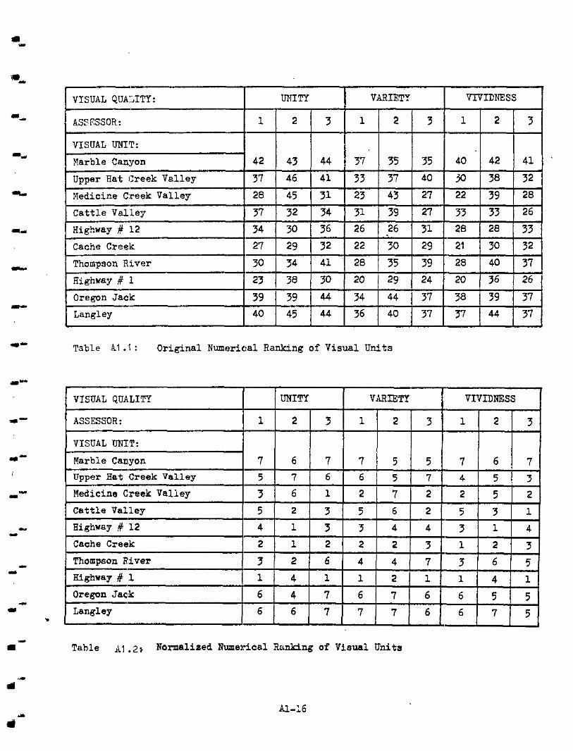
"
m
[VISUAL QUALITY: I I VARIETY
ASSESSOR:
VISUAL u " r : Flarble Can:yon
Upper Hat (Creek Valley
Medicine C:reek Valley
Cattle Valley
Highway d 12
Cache Creek
Thompson River
Highway # 1 Oregon Jack
Langley . Table AI :I : Original Numerical Ranking of Visual Units

m
m
I'
l l '
J.
I
VISUA,L QUALITY
VISUAL UNIT:
[~Merble Canyon I 57 Outstanding I Upper Hat Creek Valley I be I Outstanding I I Medicine
Creek Valley 50 I
High
Highway # 1 2
Outstanding Langley 57 Outstanding Oregon Jack
, F a i r t o Poor Highway if 1 16 Thompson River
Fa i r t o Poor Cache Creek Average
* Sum of normalized scores f o r uni ty , var ie ty , and vividness.
Table A1 .?: Sum o f Normalized Scores and Level of Visual Qual i ty
Y
I
rl A1-17

APPENDIX B
E1 .O EVALUATION CRITERIA
B1 . I CRITF3.I.A FCR EULUATING T ! E VISUAL INPACT OF FORM
Desc:ription f o r High Impact Description o f Low Impact "
I J
I .. 1
n
rl
CONTRAST: Exposed elements have contrast ing textures , shapes, and colours that compete with existing fea.tures o f t.he v isua l unit. L i n e a elements total ly disregard topo,graphy of natural 1an.d- scape.
COMPLEXENTS: Structures and
elcphasized or concealed behind other man-made elements are de-
by reLat ing to the shape, colour, existing landscape components,
and texture of the unit .
DOMIXATES: Project elements CONFORMS: Scale, shape o r disregard exis t ing scale o r structure of the project element s t rua ture within the v i sua l unit and become the focal point of the uni t .
i s modified to re la , t ;e to exis t ing landscape forms.
DEGRlLCES: Project elements d i s rupt ex is t ing vistas with the i r locat ion and form. No appaxent functional organiza- t ion of project elements compete with natural visual uni tg .
var ie ty , s c a l e , and i n t e r e s t t o ENHANCES: Project elements add
v i s u a l wit. Linear elements aligned with exis t ing water courses o r topograptly to re - inforce and organize visual q u a l i t i e s i n unit.
B1 - 1
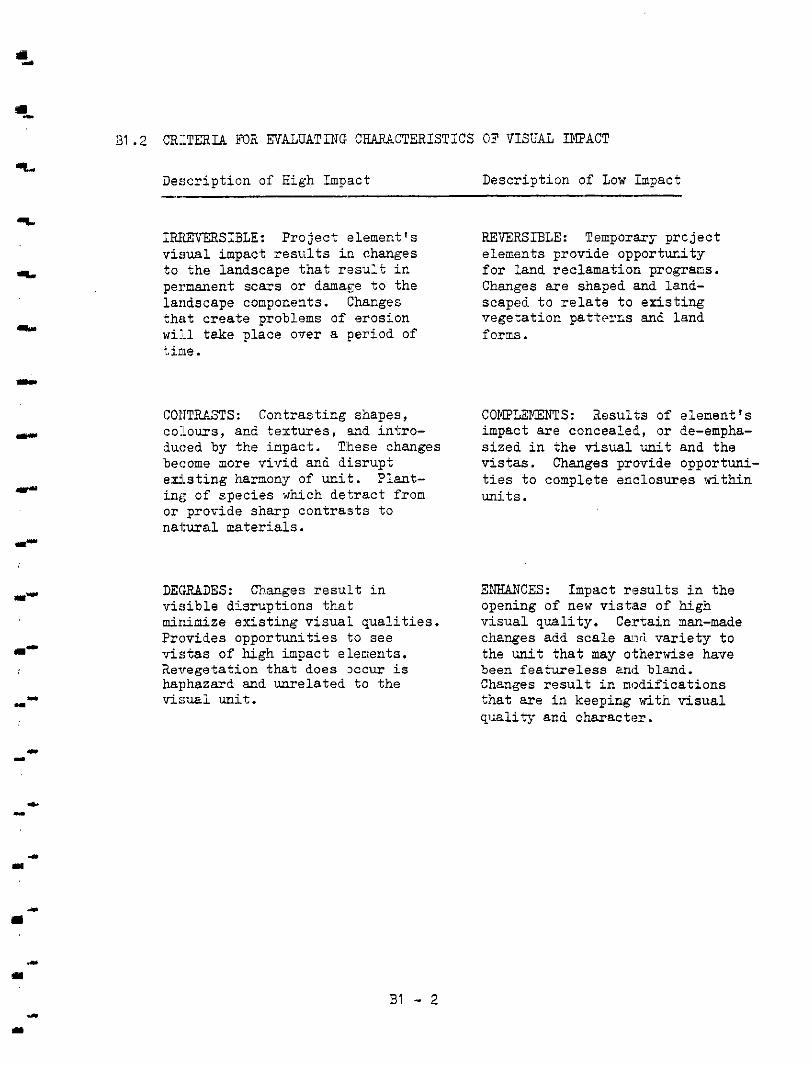
"
1,
E
31.2 CKTERIA FOB EVALUATING CHARACTERISTICS OF VISUAL IMPACT
Description o f High Impact Description of Low Impact
IELEVERSIBLE: Project element's visual impact resul ts i." changes to the l andscape tha t resu l t ir. pernanent scars or damage t o t h e landscape components. Changes
will take place over a period of t ha t c r ea t e problems of erosion
t.ime.
COI'ITUSTS: Contrasting shapes, co:!ours, and tex tures , and intro- duced by the impact. These changes become more vivid an6 disrupt ex is t ing harmony of unit. Plant- ing of species which detract f r o m or provide sharp contrasts to natural mater ia ls .
DE(:XADES: C h a g e s r e s u l t i n v i s ib le d i s rupt ions tha t minimize ex is t ing v i sua l qua l i t i es . Provides opportunities t o see v i s t a s of high impact elenents. Revegetation that does x c u r i s haphazard end unrelated to the vis~i unit .
REVERSIBLE: Temporary prcject
for land reclamation program. elements provide opportuzity
Changes a re shaped and land- scaped t o re la te t o ex is t ing vegetation patterns an6 land forms .
COMPLEKEWS: Results of element's impact are concealed, or de-empha- s ized i n the visual unit and the v i s t a s . Changes provide opportuni- ties t o complete enclosures within uni t s .
ENHANCES: Impact rsesults i n the
visual quali ty. Certain man-made opening of new vist.ss of high
changes add sca l e mri var ie ty t o
been fea ture less and bland. the unit t h a t may o.therwise have
Changes r e s u l t i n modifications t h a t a r e i n keeping with visual qiizlity and character.
B1 - 2

B1 .3 VISI.IN IMPACT ASSESSMENT
..-
""
Each impact cause and Che v i sua l units affected (See Figure 5.1) were
evaluated according t o the c r i te r ia ou t l ined i n B1 .1 and B1 .2.
Figure B 1-1 lists the numerical rankings assigned by the assessclrs t o each imptact cause and visual uni t . Fibure B 1-2 was the average ranking
of the visual impact of a project element on the visual units tha t were
affscted. The ranking of visual impacts fa l ls i n t o f ive categories . The
highest .Lev21 of v i sua l impact was designated as "extreme". A t t:he next
level , which also contained the largest number of project elements, were
those assigned a "high" level of visual impact. The "moderate" level
.comprised those in the third category, while those in the fourth level
were designated as having "low" visual impact. The lowest level. of
visual inpact was designated "insignificant". Figure B 1-2 also lists the number o f v i sua l units affected by each project element consi,dered i n the visual impact assessment.
.I-
B1 - 3
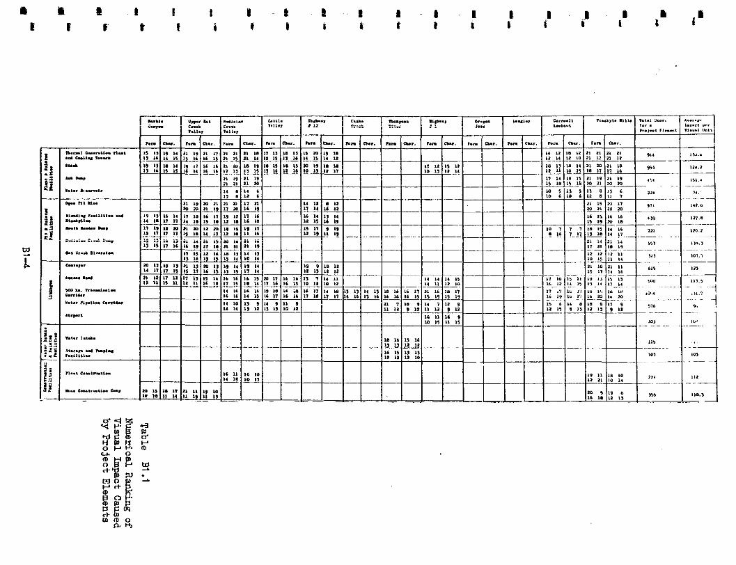
m b
1) - ."
"
Project Element Average
Number o f
Impact Affected Ranking Visual Visual Units Level of
.[Ash Dump 151.4 1
Open Pi.t Mine 142.8 4 High
Medicine Creek Dump
500 Kv. Transmission Corridor Generation Plant and Cooling Tower 130.6 L " 4
Illending F a c i l i t i e s and Stockpile
::tack 123.0
Houth Meadows Dump 120.2 6 High
Construction Camp
Water Intake
Access Road Moderate Camp 112.0 4 Moderate
Hat Creek Diversion 107.7 3 Moderate
Airport 103.0 1 Moderate
Storage and Pumping F a c i l i t i e s 103 .O 3 Water Pipeline Corr idor 96.0 6
_" " ""
Low Low
" -
>
Table 131.2 Average Ranking of Visual Impacts
B1-5
Cr i t e r i a
Visual Quality Views Visual Impact u. Pr io r i ty
Ip. 1
Foreground - High Outstanding - High - Average 2
Middleground Foreground - Extreme Outstanding - High - Ave.rage
Middleground
3 Outstanding - High - Average Extreme Background 4 Moderate Outstanding - High - Avexage
5 Outstanding - High - Ave:rage High Background
m -
I' Foreground - Middleground
" Foreground - Extreme - High - Fai r t o Poor 6 Moderate Middleground -
Background
Middleground - Background
I" Foreground - Low - Insignif icant Outstanding - High - Average 7
" I I I I
.. .. Table Bl.3 Visual Impact P r io r i ty Cr i t e r i a
BPPENDIX c
a.
1 -
R I
.I
.
a 1
C1 .O IMPACT ASSESSMEfTT MATRICES AND FORMS
The following matrices summarize the f indings of this study on Aesthetic
Considerations. Resources- on this matr ix refer t o the visual resources
of the study area which has been divided i n t o v i sua l units and spec ia l
features . The exis t ing qual i ty has been ranked i n Appendix A and the
s ignif icance of the impact in Appendix B.
The format f o r the matrices i.s based on ESCLEC's f o r n "1. It provided
a common form for recording f indings from the various environmental studies.
For this s tudy the entr ies that have o r have not been made are explained
below.
No en t r i e s have been made und.er absolute o r percentage amounts because the
f igures .would be misleading end in most c a s e s d i f f i c u l t t o calcu3.ate unless
extensive use o f the computer was made. However, during the assessment o f
the visu,sl impact, approximate areas of the viewable areas f o r each project
element 'were considered. These approximations were determined from f i e l d
observations and topographic maps.
The lett l?r designation entered under exis t ing qual i ty are taken f rom Table
A 1-3. :In appendix A 1.0 the methodology and the s ignif icance of these designations are reviewed.
Under imqact significance, le t ter designations have been entered which indi-
cate the importance of the visual impact caused by a project element on each
visual unit. Appendix B 1.0 reviews t h e c r i t e r i a and the evaluation. The
en t r i e s on the following forms are taken from Table B 1-1. The following a r e the range of numerical values used t o c l a s s i f y each impact:
m .
c1 - 1 . a
I .
I. Extreme : 140 and over
High: 110 t o 139 Moderate: 80 t o 110 Low: 40 t o 79 Insignificant: 39 and under
I
. m
. w
c1 - 2
C1 .2 MATRICES
1,
Izr
I..
a-
The fol lowing matrices have been completed as a sumaary o f this s tudy 's
f indings ,and f o r review and ar.alysis by others involved in the environ-
mental st'Jdy.
Matrix 1
Matrix 2
Matrix 3 Katrix 4 Matrix 5 i h t r i x 6 Matrix 7 Matrix 8
Matrix 9 Matrix 10
Matrix 11 Matrix 12
Matrix 13 Matrix 14 Matrix 15 Matrix 16 Matrix 17 Ma+xix 18
G.eneration Plant and Cooling Towers
:;tack
Ash Dump Water Reservoir
C'pen P i t f i n e
E,lending F a c i l i t i e s and Stockpiles
Hyouth Ifeadow Dump
Nedicine Creek Dunp
Rat Creek Diversion
Conveyor 500 kv Transmission Corridor
Water Pipeline Corridor
Airport
Water Intake Storage and -ping F a c i l i t i e s
P l a n t Construction Camp
Mine Constructicn Camp Access Road
I..-
"
c1 - 3
" PROJ-LCT SLEI>aiT GFNFRATION PLANT ATE COOLI1G TOWFRS
IUTRIX 1 ]?OR BREA SEE FIGURE 1-1 ( A , B, C-2, & C-3) SHEFP 1-1
a PBASE OPERATION - PREPARED BY XNP RUSSELL BUCKWELL & PARTNERS DATE JAN. 1978
-
" RESOURCE I I momm
ABSOLUTE % Visual Units
Narble Canyon
9 - Upper Hat I Creek Valley .. Nedicine Creek r Valley 'r Cattle Valley
Highway #12
Thompson
Highway #1 - r Oregon Jack
- r Langley I
Cornwall
Trachyte H i l l
- e
~
EXISTING, QUALITY
-I-
O
0
H
H
A
F
H
F
0
0
-
0
6
IMPACT SIGNIFICANCE H EXTRR4E I HIGH I MODERATE
B
F & B
LOW "
"
INSIGN,
NOTES: No en t r i e s were made i n this column since figures are misleading and - i n mmy cases indetermina,te, - ** Letter designation indicates type of viev: F - Foreground, 13 - ICiddleground B - Background.
Existing Quality: 0 - Outstanding - - A - Average H - High
F - Fair t o Poor *
m
r II
c1 - 4
* PROJZCT ELEI-ii iT STACK 9 n
- MATRIX 2 FOR aREA SZE FIGURE 1-1 ( A , B, C-2, & C-3)
I s m m 1-1 -
-PHASE OPERATION - PREPARED BY RUSSELL BUCKWELL & PARTNERS DA'I'E JAN. 1978
Ilerble Canyon
Upper Eat wk Creek Valley
u, Cattle Valley ,r
Highway #12
r Cache Creek
Thompson
-I
I
, r RTr Fiighway #I
1' Oregon Jack 1
I Laagley , r
SDecial -r Features
-r Lookout
Comwall
Trachyte Hill
r "
"
QUaLIl'Y
0
0
H
H
CE H MODERATE
B
:NSIGN,
"
NOTES: * No e n t r i e s were made in this column s ince f igures m e misleading and
I.., ** Letter designation indicates type of view: F - Foreground, M - IdIiddleground in many cases indeterninst:e.
Existbg Quality: 0 - Outstanding B - Bac-ound.
-,- H - High A - Average F - Fair t o Poor
mr
a- c1 - 5
a. PROJXCT ELEItENT DUMP - IMTRIX 3 P3R AREA SEE F I G W 1-1 (A. B, C-2, & C-3) sIE:m 1-1 - PHASE OPERATION - PREPARED By TOBY RUSSELL BU-LL & PARTNERS DATE JAN. 1978
RESOURCE I *
,I Visual U n i t s
1 Ihrb le Canyon ..
7 - Valley Medicine Creek
Cattle Valley - 7 Highway' #I 2
.I - Cache Creek I
' Thompson . I River
.I I : Highway #I
-+ -j Oregon Jack
Langley
Features Cornua l1 Lookout
Trachyte H i l l
.sssld.
m
-I-
"
A
"
"
EXISTING QULITY
0
0
H
H
A
F
H
F
0
0
0
H
I I- IMPBCT S EXTREME
F
M
: N I F I U HIGH c_
-
-
B
CE * MODERATE "
MW :NSIGN-
1 -
NOTES: No en t r i e s were made in this column since f igures are mislead.ing and
I
I
*+ Letter designation indicates type o f view: F - Foreground, E!; - Middleground i n many cases inde temimte .
Existing Quality: 0 - Outstanding B - Background.
H - FIigh A - Average F - Fair t o Poor
C1 - 6

"
i RESOURCE
" Visual Uni t s
I Harble Canyon
-1 - Upper Hat I Creek Valley
Nedicine Creek -1- val ley
-1 Highuay #12
-I" Cache Creek
Thompson I - River
Cattle Valley I
I :'
Highmy #1 Qr Oregon Jack
Langley
-i - Features
SDecial
' Cornwall Lookout
Trachyte H i l l
T "
"
EXISTING QU4LIl'Y
~~
0
0
H
H
A
F H
F
0
0
0
E
r "
LOW
M
"
M
CNSIGN-
I ...
NOTES: No e n t r i e s were made in +:his column s ince f igures are misleac,ing and
* i n many cases indeterminate. - ** Letter designat ion indicates type of view: F - Foreground, I[ - Middleground
B - Bac-owd. Existing Quality: 0 - Outstanding .. - H - High
A - Average F - F a t r t o Poor
1 Im
a ..0
c1 - 7
-. PROSiCT ELEI.1ENT
I4ATRIX Fl3R BREA SEE FIGURE 1-1 ( A , E, C-2. & C-3) sHxm 1-1
- o m PIT mm
- PHASE OPERATION - PREPARED BY RUSSELL BUCKWELL & PARTNERS DATE JAN. 1978
- # I
RESOURCE
1
I.
Visual Uni t s
I Marble Canyon
-1- Upper Hat Creek Valley
.-r Valley Medicine Creek
Cattle Valley
a[ Highway ,+12
, I I- Cache Creek
Thompson
-r 7 Eiighvay #1 'r Oregon Jack
Langley -+ "
-r ' Cornwall
l r Lookout
, I Trachyte Hill
"
-
"
T EXISTING QUALITY
0
0
H
H
A
F H
F
0
0
0
B
B
NOTES: * No e n t r i e s were made in t h i s column s ince f igures are misleading Bnd in many c m e s indetermina-te. . +* Letter designat ion indicates ty-pe of view: F - Foreground, I1 - Iiliddleground
I
Existing Quality: 0 - Outstanding B - Background.
.)
1. H - High A - Average F - Fax t o Poor
C1 - 8
II .
MATRIX 6 FOR AREA SEE FIGURE 1-1 ( A , B, C-2, & C-3)
PHASE OPERATION - PREPARED BY RUSSELL B U W L L & PARTNERS
Visual U n i t s mr I
1 I-Iarble Canyon
I. Upper Hat I Creek Valley
7 . Medicine Creek Valley
. Cattle Valley
1 Highway #12
?- Cache Creek
’I- R.lver
Thompson
Highway #l
7- Oregon Jack
. Langley II
1- Features
SDeclal
Cornvall Lookout
Trachyte Hill I
r ”
”
smm 1-1
0
0
H
H
A
F H
F
0
0
0
E
:IfIFI CJ HIGH 7
-
F
F
B
-
B
F
”
CNSIGN-
NOTES: No e n t r i e s were made in t h i s column s ince f igures are misleading and . i n marly cases indeterminat:e. - H Letter designation indicates type of view: F - Foreground, M - Ifiddleground
Existing Quality: 0 - 0ut:standing B - Background. - H - Hidl
a A - Ave:rage F - Fai:r t o .Poor
I
I
s I
c1 - 9

.. RESOURCE I-
I P Visual U n i t s
I b r b l e Canyon
Upper Hat Creek Valley
I* Medicine Creek r Valley
~~ Cattle Valley
Highway #12
F- Cache Creek
Thompson River *' &hway #1
I
-r Oregon Jack
MOUNT * BSOLUTE % T : N I F I C J
HIGH __.
M
"M
B
M & B
-
B -
?E H
XODEMTE M Y
"
B
:NSIGN,
- I NOTES: No e n t r i e s were made in this column since f igu res are misleading and
* i n many cases indeterminate. - ** Letter designat ion indicates type of view: F - Foreground, I4 - 14iddleground
B - Backpound. E d s t : L n g Quality: 0 - 0ut:atanding
* H - Hierh - A - Average F - Fair t o Poor
m y
c1 - LO

MATRIX 9 FOR AREA SEE FIGURE 1-1 (A, B, C-2, & C-3) smm 1-1
- PHASE OPERATION - PREPARED BY RUSSELL BUcKlJELL & PARTNERS DATE JAN. 1978
I Ikrble Canyon
8 - Upper Hat Creek Valley
.I
L Medicine Creek ' Valley w I Catt le Val ley
i I I
Highway #12 I ' 1- Cache Creek
Thompson '- River I : 7"
Highway #I
' I Oregon Jack
Trachyte B i l l
EXISTRfG QWLITY
0
0
H
H
A
F
H
F
0
0
0
H
B
F & M
F & B
NOTES: No entries were made in this c o l m since figures are misleading and T , - i n many cases i ade ten ina te . ** Letter designat ion indicates type of view: F - Foreground, M - Aiddleground
B - Bac-ound. y . Existing Quality: 0 - Outstanding
A - Average H - High 3' - Fair t o Poor
1.
C t - 11
- RESOURCE
L r Narble Canyon
Visual Units
7 Upper Hat Creek Valley
Medicine Creek r Valley
- , ~ Cattle Valley
Highway #I 2
? Cache Creek
Thompson 1
'r Highway #I or begon Jack
Cornwall Lookout
d ' Trachyte H i l l
"
: N I F I C I HIGH - -
F & M
?E ++
NODERATE
M
B
" mw "
"
i
XSIGN.
NOTES: No e n t r i e s were made in this column since f igures are misleading and in many cases indetanai?a,te. - - Lettor designat ion indicates type of viev: F - Foreground, If - 14iddleground
Exist'ing Quality: 0 - Outstanding B - Background.
" H - Hi& ~
A - Average F - F a i r t o Poor
rl~-
a - I -
c1 - 12
II
.a PROJECT ELEIUNT CoNVFYoR
MATRIX 10 FOR AREA SEE FICrmE 1-1 ( A , B, C-2. & C-3)
-
* m m 1-1
- PRASE OPERATION - PREFARED BY TOB]I RUSSELL BUCKWELL & PAii"NERs DATE JAN. 1978
.I Visual U n i t s r-
I k r b l e Canyon
r
- Upper Hat Creek Valley
Medicine Creek
I
.I r val ley
'I Catt le Val ley
1 Highway #12
' .. Cache Creek
Thompson
.. c
.L Ikghway #l
' r Oregon Jack
l o 0
H
H
A
F E
F
0
0
Cornwall Lookout -' Trachyte Hill
" -
-r IMPACT S EXTREME
:E * vlODERATI
"
"
NOTES: * No er l t r ies were made in this column s ince f igures are misleading and
- . i n mtrny cases indetemimrte. ** Let te r des igna t ion ind ia tes type of view: F - Foreground, II - IGiddleground
B - Background. Existing Quality: 0 - Outstanding
'c, A - Average H - High F - Fair t o Poor
I.
C1 - 13
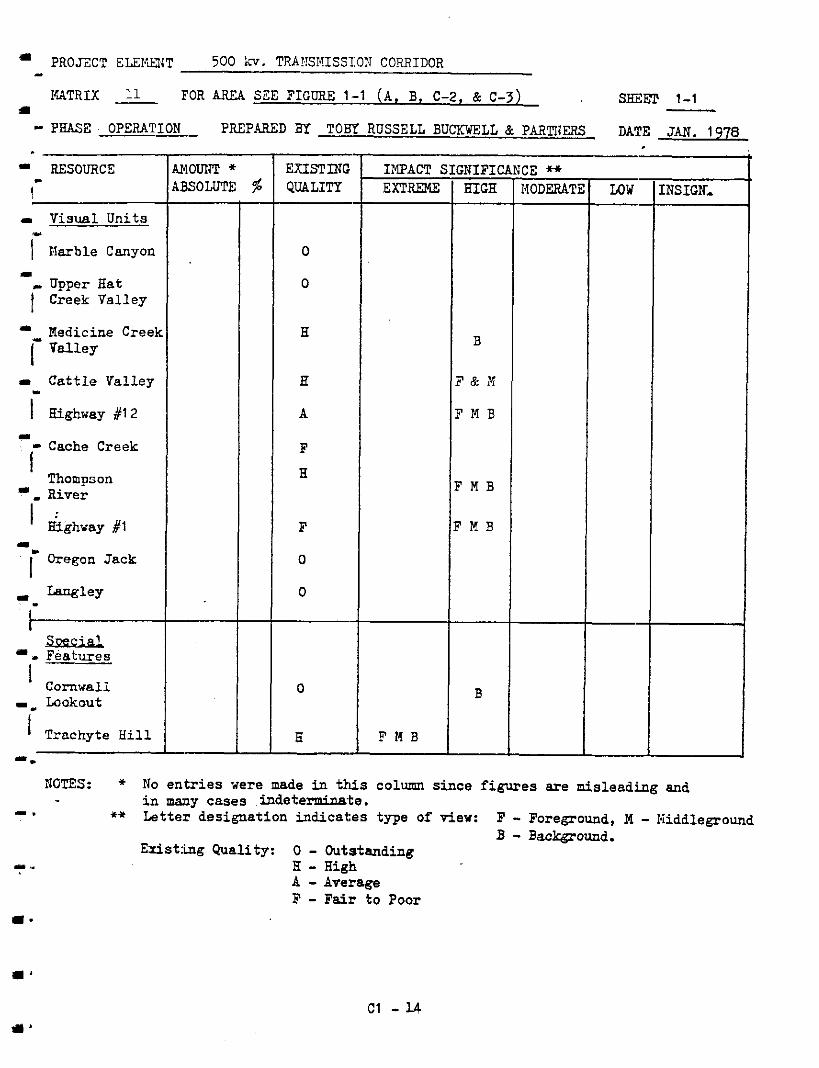
- PROJZCT ELEItENT 500 LC. TRAI,TSSnISSI:ON CORRIDOR -
I'ATRIX 11 FOR AREA SEE FIGURE 1-1 ( A , B, C-2, & C-3) a
smm 1-1
- PHASE OPEPATION - PREPARED By T O B Y R U S S E L L BUCKWELL & PARTIiEFS DA1!E JAN. 1978
RESOURCE \ - .I Visual Units
1" Aarble Canyon I
E L e Y
Hedicine Creek i Valley
= Cattle Valley
I Highway #12
'. [- Cache Creek
Thompson Ever ' &ghway #1
- I
.. m
Oregon Jack
Langley "
SBxklI, Features
I 1 Cornwall
Lookout
-i Trachyte Hill "
T T t 0
0
H
E
A
F H
F
0
0
0
6 F M B
B
F & W
F M B
F M B
F M B
B
:NSIGN,
NOTES: * No entr ies were made in this column since figures are mislead,ing and - I .
i n many cases .indeterminate. *i! Letter designation indicates type of viev: F - Foreground, M - Kiddlegroud
Exis t f ig Guality: 0 - Outstanding B - Bac-ound.
I* H - High A - Average F - Fair t o Poor
1.
c1 -L4
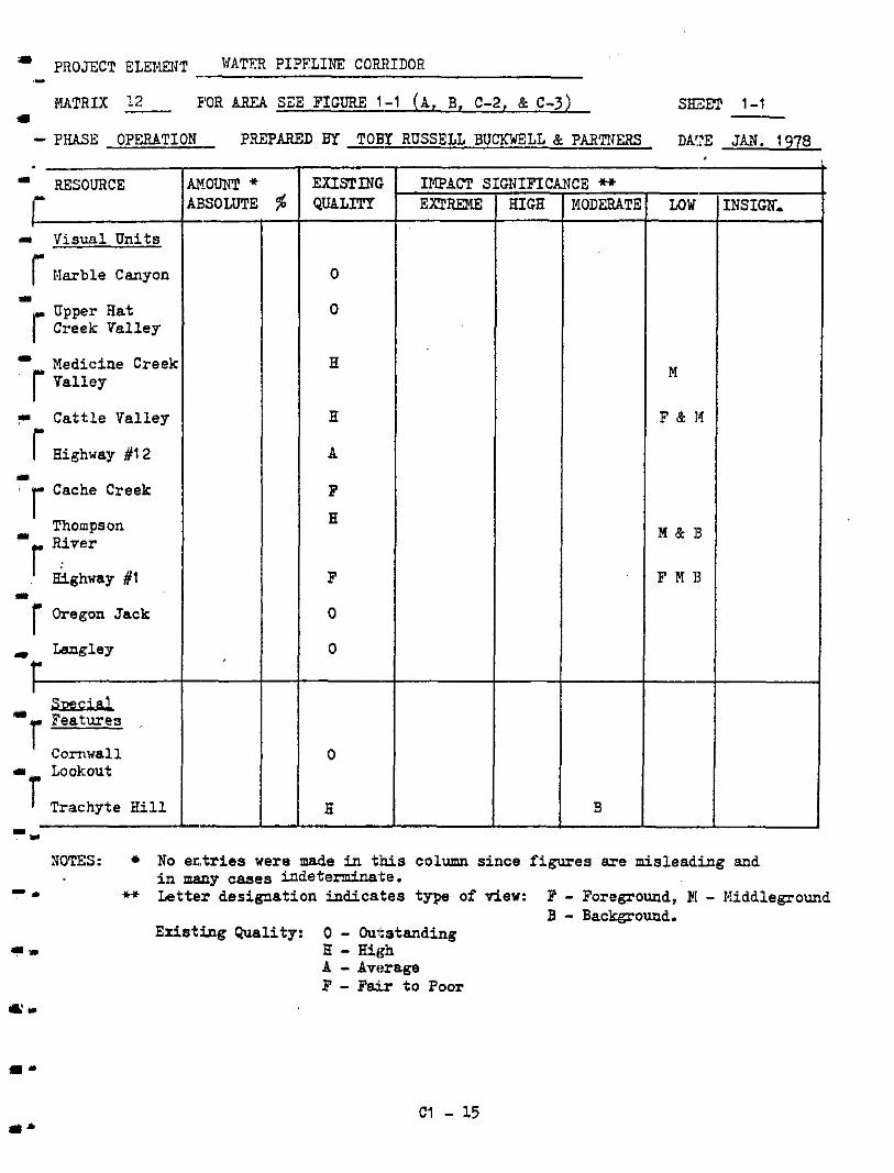
RESOURCE
L" r Harble Canyon
r) Visual Units
I Medicine Creek r Valley
7 Cattle Valley r Highway #I2
I Thompson
r Sfghway #1
* River
I r Oregon Jack
r a Langley
I
1 Lookout
Trachyte Hill
-u
-I 0
0
H
H
A
F H
F
0
0
IlQACT 5 EXTREME
FIOTES: No e n t r i e s were made in t:his column since figures are mislead.ing and
-111 i n many cases indeterminate.
** Letter designat ion indicates type of view: F - Foreground, EL - Niddleground
Existing Quality: 0 - Outstanding B - Background.
I - H - High A - Average F - F ~ x t o FOOT
Il"
C1 - 15
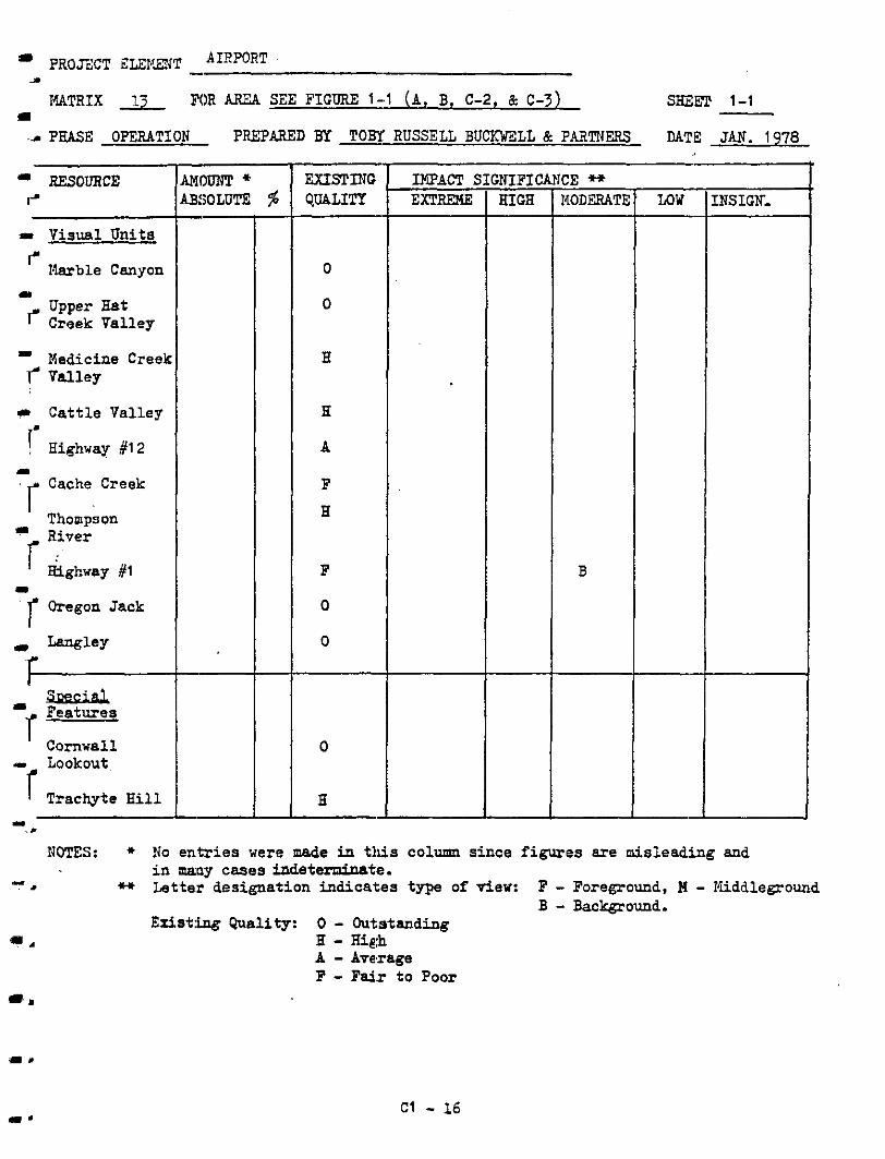
- PROJECT ELEI*LENT A I R P O R T - s
I I4ATRIX & FOR AREA SEE FIGURE 1-1 ( A , B. C-2, & C-3) SHmT 1-1
-- PEASE OPERATION - PREPARED BY RUSSELL B U W L L & P A a T N E R s DATE JAN. 1978 - RESOURCE r=
w Visual Units I- I.larble Canyon
Creek Valley Upper Bat
Medicine Creek Valley
m
i
1 Cattle Valley
Highway #12
~ r Cache. Creek
Thompson River
Gghway #l
rl
I
I r h e g o n ~ a c k
" ' r Features
-r Lookout
I) Langley
I iiRQ&Jb
Cornwall
I Trachyte H i l l I _.
'I-
O
H
H
A
F
H
F
0
0
INTACT S EXTRF3.E
NOTES: * No e n t r i e s were made i n this column since f igures are misleading and
I
in many c m e s indeterminate. H Lette,r designation indicates typi, of view: F - Foregound, M - Kuddleground
Existing Quality: 0 - Outstanding B - Background.
5 . H - H i & A - Average F - Fair t o Poor I..
Cl - 16
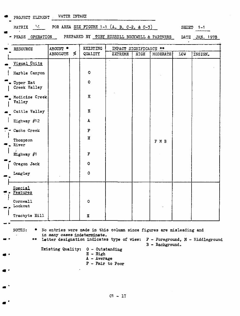
IUTRIX x FOR BREA SEE FIGURE 1-1 ( A , B, C-2, & C-3) smm 1-1 ;I - PHASE OPERATION - PREPARED BT z r RUSSELL BUCKWELL L+ PARTNERS DATE JAN. 1 978
.I RESOURCE
1- - Visual Units
I I-larble Canyon
I Creek Valley I Upper Hat
L
I
Medicine Creel
I I
Cattle Valley - t Highway #12
I 1 - Cache Creek
I Thompson
I. River
= e
I Oregon Jack
t"--- mi
SDeciel
' Cornwall - Lookout
Trachyte H i l l
-*"
Lilomm LBSOLUTE $ "
l- EXISTING QUALITT
0
0
H
H
A
F
H
F
0
0
0
6
r IMPACT E EXTREME
CE H MODERATE
F M B
"
LOW "
INSIGN. f t
NOTES: No e n t r i e s were made in this column since figures are misleading and i n m a y cases indeterminate.
** Lette:r designation indicates type of view: F - Foreground, 11 - Kiddleground B - Background.
Edstfing Quality: 0 - Out,standing H - High A - Average F - Fai r t o Poor
C1 - 17

I I Visual Units I
I Narbie Canyon
a Upper Hat 1 Creek Valley - Medicine Creek i Valley
.I
-i Cattle Valley
Highway #12
Thompson
ighway #l r begon Jack
U Langley
Cornwall Lookout ' Trachyte Hill
"
r EXISTING QUALITY
0
0
H
H
A
F H
F
0
0
0
H
I
F & M
"
LOW
"
"
INSIGN.
NOTES: * No e n t r i e s were made in this column since figures are misleading and
I- i n mirny cases indeterminate.
.*+ Letter designat ion indicates zype of viev: F - Foreground, N - 1.liddleground
Exist,ing Qual i ty: 0 - Outstanding B - Eackgcound.
m - H - H i , & A - Avsrage F - Fair t o Poor
"
Q I
c1 - 18

..* I) 7 I Visual U n i t s "
I Barble Canyon
. Upper Hat I Creek Valley
(.
1
Medicine Creek *
I il Cattle Valley
I Highway #12
?- Cache Creek
Thompson
..
I - River
I Highway #l
I Oregon Jack
i"-----
"
I Laagley
7- Soecia!.
Cornwall - Lookout
Trachyte Hill
c.
MOmPT B,SOLUTE % "
"
"
l- EXISTING QUALITT
0
0
H
H
A
F
H
F
0
0
0
B 1 -
M
AN(
T "
LOW
"
"
NS IGN,
XOTES: * No en , t r ies were made in this column since f igures are misleading and
I -
in many cases indeterminat:e. +* Letter designat ion indicates type of view: F - Foreground, M - Iuddleground
B - Background. Existing Qual i ty: 0 - Outstanding
" H - High A - Average 3' - Fair t o Poor
I-
c1 - 19
r. P R O ~ C T ELEI:I~{T YIN'Z 'CONSTRUCTION CAE? . - MATRIX 17 FOR AREA SEE FIGURE 1-1 ( A , B, C-2, & C-3) smm 1-1
rn . PHASE OPERATION - PREPARED BY RUSSELL BUCKWELL & PARTNERS DAT:E JAN. 1978
I RESOURCE
I - Visual Units
' 1,larble Canyon
I
I Creek Valley
c. Nedicine Creel
. Upper Hat
I Valley
-. Cattle Valley
' Highway #I 2
? * Cache Creek
Thompson I I River
I :
I
c"-------
Highway #I
Oregon Jack U.
.I. Langley
sEfi€id p * Features
Cornwall Lookout
Trachyte H i l l
I I*
I - "
EXISPDfG QUALITY
0
0
H
H
A
F
H
F
0
0
0
H
I IKF'ACT S EXTI(EME
CE H I4OD'ZMTE
B
:NSIGN.
HOTES: * No e n t r i e s were made in t W s column s ince f igures a re mis1ead:ing and i n many cases indeterminate.
II *+ Letter designation indicat:es type of view: F - Foreground, M - I(idd1eground
I' H - High Exis t ing Guality: 0 - Outstanding
B - Background.
A - Aversge F - Fai r t o Poor
a'
c1 - 20
PROJ'ECT ELENENT
MATRIX x FOR AREA SEE FIGURE 1-1 (A, B, C-2, & C-3) s=:m 1-1
ACCFSS ROAD I -
.I
'P'HASE OPERATION - PREPARED BY RUSSELL BUCKWELL & PARTNERS DATE JAN. 1978
RESOURCE I . .I Visual Units
I 1.lIarble Canyon I
I Creek Valley LI Upper Hat
Medicine Creek I * val ley
I I Cattle Valley
I Highway #12
' Cache Creek
Thompson
.. I
I
I : . River
Hi6hway #1 - "
I Oregon Jack -.
"
"
r E X I S T I N G QUALITY
0
0
H
H
A
F
H
F
0
0
0
6
t IMPACT 2 EXT(TREME
B
F & M
F & M
F & I,!
F & M
B
F & M
"
LOW "
B
"
[NSIGN,
IiPOTES: No e n t r i e s were made in this column s ince f igures are misleading and
I" i n many cases indeteminate.
+* Letter designation indicates type of view: F - Foreground, I4 - 1;iddleground B - Background.
Existing Quality: 0 - Out;standing ? m E - High
A - Average F - Falx t o Poor * =
a' C l - 21
Q I
I
AF’PEITDIX D
Dl .O I W ” f C E SECTION
Dl .1 FOOTNOTES
1 . Redding, I k t i r . J. 1975 Aesthetics in Environmental Planning. U. S. Government Pr int ing Off ice , Washington, D.C.
2. Ib id . , p.dO.
3 . Fvrest Service, U. S. Department of Agriculture. 1974. National Foresf Landscape Management Vol.ume 2, Chapter 1, The Visual Management System., U. S. Government Pr int ing Off ice , Washington, D.C.
4. Redding. Op. c i t . p.51.,
5. Ib id . , p.51.
6 . Environment and Land-Use Sub-committee on Northeast Coal Development. May, 1977. Northeast Coal Study: Preliminary Environmenta:L Report on Proposed Transportation L i n k s an2 Townsites. Victoria, B.C..
7. Li t ton, R. Eurton, Jr., Robert J. Tetlow, J. Sorenson, and L A . Beatty.
Washington, N. Y. 1974. Water and Landscape. Water Information Centre, Inc., Port
Dl - 1
Dl .2 BIBIJOGRBPHY
-. -. - *
-. 1.
-. I.
"
Arthur, Louise M., and Ron S. Boster. 1976. Measwing Scenic Bea.uty: A Selected Annotated Bibliograpny. U. S. Department of Agriculture, Washington, D.C.
Bacon, Warren, and Paul F. Hanson. 1972. The Visual MWagenent System - Pacif ic Northwest Region. Forest Service, U.S. Department Of Agriculture, Washington, D. C.
Energy - Elnvironment Dilemma. National Academy O f Engineering, Washington, Comnittee on Power P lan t S i t ing . 1972. Engineering for Resolution of
D. C.
Environment and Land Use Commi-ttee Secre ta r ia t . 1976. Guidelines for Coal DeveLopment. Parliament Buildings, Victoria, B. C.
Forest Service, U.S. Department; o f Agriculture. 1977. Smith Rive]: Highway Visual Analysis Study. U.S. Government Pr int ing Off ice , Washington, D. C.
"~"~""~ . 1975. National Forest Landscape Managenent Volwne 2. Chapter 3 :Range. U.S. Government Printing Office, Washington, D. C:.
. 1976. National Forest Landscape Management Volume i!. Chapter 4 2oads. U.S. Government Pr in t i rg Off ice , Washington, D. C!.
Jones, G r a n t R., I lze Jones, Brian A. Gray, Bud Parker, Jon C. Coe, J o h n B. E u m h a n , and Neil M. Geitner. 1975. Guantification of Aesthetic Values f o r Environmental Decision Making. Nuclear Technology 25:682 - 721.
Resource Analysis Branch. 1977. Proceedirgs: Visual Analysis Workshop. Ninistry o f the Environment, Vi-toria, E.C.
Robinette, Gary 0. 1973. Ener ,g and Environment. ICendall/Eunt Pu'blishing Company, Dubuque, Iowa.
Yoenans, W. C. 1975. Spallumcheen: The Visual Environment. B.C. Land Commission, Burnaby, B. C.
""""
Environment and Land Use Committee Secretar ia t , Victor ia , B.C. . 1?75. Lardscape Architecture and the Visual Resource.
Environment, Victoria, E. C. """""" . 1977. Adans River - A Resource Analysis. Ministry of the
r' ,
31 - 2

Dl . 3 GLClSSARY
1-
I -
"
1-
..-
Axial approach is one tha t fo:Llows a main l i n e of d i r ec t ion forme': by the
l i nea r arrangement of land foj?rts and man-made elements.
-ound " r e f e r s t o d i s t a n t views that are usually over 5 km. away from
the observer.
- Berms r e f e r t o man-made landforms o r mounds tha t t ave been in tegra ted in to
the existing landscape to provide visual screens o r enclosures. They are made from ea r th f i l l and covered with topsoil to accomodate a va;?iety of
vegetation types.
Boundary def ini t ion deals with those character is t ics which visual:!y
e s t ab l i sh t he pe rke te r o r edge of the visual uni t wi thin i t s general area.
Character is t ics of v i sua l impa,act caused by a project element consist of a l l
the factors, with the exception of fo rms , that v isual ly affect the perceived
qua l i ty of the existing environment.
1
I
Colour enables the observer to different ia te objects having similar form
or texture.
Comnansation measures are taken to provide alternative actions f o r visual
impacts t h a t cannot be adequat:ely mitigated.
Contrast ,provides visual compcsiti.ons in which t h e i r components a re immedi-
ately app,erent t o the observer because of the use of 2 var i e ty o f fo rm,
colour, l .ine and texture.
Convergenlz occurs when major landforms, l i n e s , and man-made elements tend to focus .the observer's attention on one point o r small area.
Dl - 3
a.
I.
i l '
- Cultural and land use pattern indicate the presence o f human occuFation as characterized by f ie ld crops, pastures , grazing areas , roads, and other man-
made e1emen.k.
Digital t e r r a i n model (DTM) i s a three dimensional grid that locates a
s e r i e s o f g r i d p o i n t s o r c e l l s from a s tereopair of a e r i a l photographs t o
a common reference point. Tho DTM i e s t o r e d i n a computer and can be used
t o generate topographic maps o r t o provide other types of analyses.
Enfraoemerl!. d i r e c t s an observer's attention inwards and can be reinforced by other dominant principles such as a x i s o r convergence.
Enclosure i s fomed by landscape components which surround o r encompass a
space.
Enhancemer& provicies addi t icna l measures to enhance the existing visual
qual i ty .
? + a t m e r e f e r s t o a landform o:c landscape component that is the f o ' z a l point of E. v i sua l un i t o r view.
Foremound: r e f e r s t o d e t a i l views within 0.8 la. o f the observer.
" Fern is the mass o f an object or combination of objects that appear unified.
rkner?l f c = re la tes p r imar i ly t o the expression of the landform such a s
mountain, planes, and valleys.
High technolorn environment refers to a s e t t i n g domi3ated by a soup of man- made elements associated with an i ndus t r i a l o r highly technical process such
as an o i l r e f ine ry .
- ImDact. is defined as a change i n the visual environment brought about by the introduction o f a project elenent.
Dl - 4

..-
I.
I-
=-
Landscape r e fe r s t o t h e t o t a l i t y of na tura l and man-aa2e surface features and e1ene:nts ir- the study area..
Landscape components a re clements o f the landscape that define it:; particu-
lar cha rac t e r i s t i c s o r f ea tu re s i n r e l a t ion t o other p a r t s o f the study area.
Landscapi:s involves the overall layout and development o f vegetation and
landforms such as t rees , shrutls, groundcover, berms, swales and open areas ,
required t o i n t eg ra t e man-made elements into the surrounding natural land-
scape. It involves enhancement and mit igat icn measures as we l l a s s i t e
er.gineeri:ng considerations.
- Line r e fe r s t o natural and man-made elenents that form a l inear pe t te rn o r row.
Man-made :refers .to elements or changes that are introduced a d produced by
man.
i4iddleprolU are views within 0.8 t o 5 kin. of the observer.
I . .
3
(I
m
Mitipation measures refer t o courses of act ion that vrlll reduce tk.e sever i ty
of the visual impact.
Portals are visual openirgs within a visua l un i t caused by depressions such
as a mountain pzss o r the natural drainage pattern.
Project a(- r e fe r s t o any action taken dining the development o f this project that causes a d i rec t o r ind i rec t change t o the exis t ing environment.
Prl),iect elements are the physical elements that result from the implementa- t i o n o f a project action.
Dl - 5
-.
-.
I"
I,
I.
I.
Receptor :LS tha t v i sua l unit o r spec ia l fea ture which is visua l ly a f fec ted
t y a proJect element.
Sua t i a l s ewence r e fe r s t o a sequence o f interconnected spaces that enhance
the observers' experience as they approach a visual feature o r focal point .
Special features are features within the study area that are not par t o f a visual unit.
Terrain pi- i s the r epe t i t i on o f forn-shape-colour-texture variation
within the landscape.
Texture can be found on the surface o f a t ree t runk o r i n a clump of de-
ciduous t r e e s vithin an evergreen forest. Texture i s dependent OE. the distance at which an object i s observed.
Varietx provides richness and divers i ty within the visual env;Lroment.
Vegetative pattern defines particular kinds o r composition of vegetation
cover having distinctive colour, texture and density.
Viewable area maps a r e maps defining points, within the study area., from which a s p e c i f i c objec t can be seen.
Visual fet- ape those elenents within the visual unit which stand out though dos inan t s ca l e , i so l a t ion , d i s t i nc t ive shape o r o ther special
character is t ics .
Visual in],act i s the change in t he v i sua l environment brought about by the introduction of a project element.
Visua l sens i t iv i ty is the capabi l i ty of the landscape to absorb visual change
o r eodifioations.
D l - b
Visual unit is an area o f dist : inctive visual character coinciding with the
visual f i , ? l d ir. which an observer accumulates an impression o f this character .
The :opogcaphy is the major c r i t e r i o r in recognizing visual units..
-
Vividness distin@;u:shes the in. tensity of visual experience by g i 7 i ~ g dis- t inct ive visual c lues .
Dl - 7