bridge geometry system (bgs) v9.1 user guide · bridge geometry system (bgs) v9.1 ......
TRANSCRIPT

December 28, 2015
January 29, 2016
Bridge Geometry
System
(BGS)
v9.1
User Guide
i
TABLE OF CONTENTS
Table of Contents ....................................................................................................................................................... i
Table of Cards .......................................................................................................................................................... vii
Table of Figures ........................................................................................................................................................ xi
Table of Tables ........................................................................................................................................................ xiv
Chapter 1: Introduction ................................................................................................................................................ 1
Purpose of this Guide ................................................................................................................................................ 1
Organization of this Guide ......................................................................................................................................... 1
Chapters ................................................................................................................................................................. 1
Appendices ............................................................................................................................................................ 2
Program DESCRIPTION ............................................................................................................................................... 2
BGS: A Bridge Geometry System .......................................................................................................................... 2
Other Documentation ............................................................................................................................................... 3
README File .......................................................................................................................................................... 4
Release Notes ........................................................................................................................................................ 4
Online Support Information .................................................................................................................................. 4
BGS User Guide ...................................................................................................................................................... 4
Chapter 2: Getting Started ............................................................................................................................................ 5
Before the User Starts ............................................................................................................................................... 5
Using BGS ................................................................................................................................................................... 5
Creating the BGS Input File .................................................................................................................................... 5
Running BGS (Processing the BGS Input File) ........................................................................................................ 5
Reviewing BGS Output ........................................................................................................................................... 5
BGS Input File ............................................................................................................................................................ 6
Defining Roadway Geometry ................................................................................................................................. 7
Initial Input File Setup ........................................................................................................................................ 7
Establishing Horizontal Alignment ..................................................................................................................... 8
Establishing Vertical Alignment ....................................................................................................................... 11
Establishing the Roadway Template ................................................................................................................ 12
Defining Bridge Geometry ................................................................................................................................... 12
Preparing BGS for Bridge Commands .............................................................................................................. 12
ELEVATION CHECKS AT POINTS OF INTEREST .................................................................................................. 13
ii
Defining Bent Lines and Slab Dimensions ........................................................................................................ 14
Establishing Bearing Seat Centerlines .............................................................................................................. 15
Defining Beam Lines and FRAME the Bridge ................................................................................................... 16
Finding Vertical Clearance ............................................................................................................................... 16
Example Input Files .................................................................................................................................................. 17
Example 1 ............................................................................................................................................................ 17
Example 2 ............................................................................................................................................................ 20
Chapter 3: General Information and Terminology ..................................................................................................... 23
Input File .................................................................................................................................................................. 23
Control and Section ................................................................................................................................................. 23
Roadway .................................................................................................................................................................. 23
Roadway Designation .............................................................................................................................................. 24
Roadway Templates ................................................................................................................................................ 24
Design Data .............................................................................................................................................................. 24
Stations .................................................................................................................................................................... 24
Station Equations ..................................................................................................................................................... 24
Alphabetic Entries .................................................................................................................................................... 25
Alphanumeric Entries .............................................................................................................................................. 25
Comments ............................................................................................................................................................... 25
Field ......................................................................................................................................................................... 25
Justifying .................................................................................................................................................................. 25
Numeric Entries ....................................................................................................................................................... 25
Real (Floating Point) Numbers ................................................................................................................................. 25
Integer Numbers ...................................................................................................................................................... 26
Explicit Decimal Point .............................................................................................................................................. 26
Implicit Decimal Point .............................................................................................................................................. 26
Process ..................................................................................................................................................................... 26
Run ........................................................................................................................................................................... 26
Diagnostic Messages................................................................................................................................................ 26
Chapter 4: System Card .............................................................................................................................................. 28
Introduction ............................................................................................................................................................. 28
SYSTEM Card Input .................................................................................................................................................. 28
PROJECT ID Field .................................................................................................................................................. 28
PROCESSES TO BE EXECUTED FIELDS ................................................................................................................... 29
iii
METRIC, JOB TYPE, KEEP, INITIALIZE GEOMERY FILES, INITIALIZE DESIGN DATA FILES, INITIALIZE BRIDGE FILES,
anD PRINT INPUT DATA FIELDS............................................................................................................................ 29
UNIT Field ............................................................................................................................................................ 29
Unit Setting ...................................................................................................................................................... 30
NAD 83 Setting ................................................................................................................................................. 30
JOB TYPE Field and SAVE RESULTS Field .............................................................................................................. 31
JOB TYPE Field .................................................................................................................................................. 31
SAVE RESULTS Field ......................................................................................................................................... 32
OMIT STORED DATA FieldS .................................................................................................................................. 32
OMIT STORED GEOMETRY DATA Field............................................................................................................. 33
OMIT STORED DESIGN DATA Field ................................................................................................................... 33
OMIT STORED BRIDGE DATA Field ................................................................................................................... 33
PRINT INPUT DATA Input Field ............................................................................................................................ 33
COMMENT Input Field ......................................................................................................................................... 34
Chapter 5: Roadway Design Data ............................................................................................................................... 35
Introduction ............................................................................................................................................................. 35
How Roadway Design Data Is Used ......................................................................................................................... 35
Horizontal Alignments ......................................................................................................................................... 36
Vertical Alignments .............................................................................................................................................. 36
Template Data ..................................................................................................................................................... 37
Superelevation and Widening Data ..................................................................................................................... 40
Stationing and Equation Scheme ......................................................................................................................... 43
Inputting Roadway Design Data .............................................................................................................................. 45
Roadway Design Data Input Cards ....................................................................................................................... 45
Horizontal Alignment Data .............................................................................................................................. 45
Superelevation and Widening Data ................................................................................................................. 67
Updating Design Data .............................................................................................................................................. 73
Deleting All Design Data for the Project .............................................................................................................. 73
Creating (Punching) and Listing Design Data ....................................................................................................... 76
Chapter 6: Command Structured Input – General Geometry..................................................................................... 79
Introduction ............................................................................................................................................................. 79
Command Structured Input CARDS ..................................................................................................................... 79
Legacy fields (Columns 1-7 and 10-12) ............................................................................................................ 79
Command (Columns 13-16) ............................................................................................................................. 80
iv
Variable Fields A, B, C, and D (Columns 17-32) ................................................................................................ 80
Variable Fields E (Columns 33-34) ................................................................................................................... 80
Variable Fields F (Columns 35-36) ................................................................................................................... 80
Other Fields (Columns 37-80) .......................................................................................................................... 80
Modifying Report Output .................................................................................................................................... 82
General Geometry ............................................................................................................................................... 83
General Geometry Commands ............................................................................................................................ 83
Roadway Elevations ........................................................................................................................................... 116
Alignment Relationship ..................................................................................................................................... 120
Creating (Punching) and Listing Stored Geometry Data .................................................................................... 123
Chapter 7: Command Structured Input – Bridge Geometry ..................................................................................... 128
Bridge Geometry Commands ................................................................................................................................ 128
Introduction ....................................................................................................................................................... 128
FUNCTION, USAGE AND INPUT SCHEMES for bridge geometry commands ..................................................... 130
Chapter 8: Command Structured Input – Plotting .................................................................................................... 218
Plotting .................................................................................................................................................................. 218
General Plotting Instructions ............................................................................................................................. 218
Horizontal Alignment Plotting ........................................................................................................................... 218
Orienting the Plot .......................................................................................................................................... 218
General Plotting Commands .............................................................................................................................. 226
Contour Plotting ................................................................................................................................................ 237
Alignment Relationship ..................................................................................................................................... 240
AREL - Compute Alignment Relationship ....................................................................................................... 240
Creating (Punching) and Listing Stored Geometry Data .................................................................................... 240
PLST - Create (Punch)/List Stored Points ....................................................................................................... 240
CLST - Create (Punch)/List Stored Curves ...................................................................................................... 240
BGPN - Transform Command Units and Punch ............................................................................................. 240
Chapter 9: Running BGS to Process the Input File .................................................................................................... 241
Starting the BGS Program ...................................................................................................................................... 241
Drag-n-Drop Method ......................................................................................................................................... 241
Command Line Method ..................................................................................................................................... 241
Running the Program ............................................................................................................................................. 241
BGS Log File ....................................................................................................................................................... 241
Plot Processing ................................................................................................................................................... 241

v
BGS Command-Line Parameters ........................................................................................................................ 241
Chapter 10: BGS Output ........................................................................................................................................... 242
Summary of Output Files ....................................................................................................................................... 242
Log File (bgs.log) ................................................................................................................................................ 242
Report Files (<filename>.ls1, .ls2, .ls3, .ls4, .ls5) ................................................................................................ 242
DGN Plot File (<filename>.dgn) ......................................................................................................................... 242
Punch file (<filename>.pch) ............................................................................................................................... 242
Punching Previously Stored Geometry Data .................................................................................................. 242
Punching Previously Stored Design Data ....................................................................................................... 242
Punch File Example ........................................................................................................................................ 242
Project Work Files .............................................................................................................................................. 242
Page File (<filename>.pag) ............................................................................................................................ 242
Bridge File (<filename>.bri) ........................................................................................................................... 242
Chapter 11: Using BGS Project Work Files ................................................................................................................ 243
Introduction ........................................................................................................................................................... 243
Project Work Files .................................................................................................................................................. 243
Page File ............................................................................................................................................................. 243
Bridge File ...................................................................................................................................................... 243
Creating Project Work Files ............................................................................................................................... 243
Using Existing Project Work Files ....................................................................................................................... 243
Using Existing Work Files (Without Updating the Files) ................................................................................ 243
Using Existing Work Files (And Updating the Files) ....................................................................................... 243
Chapter 12: Example Bridge Projects ....................................................................................................................... 244
Small Bridge Project ............................................................................................................................................... 244
Large Bridge Project............................................................................................................................................... 244
Appendix A: BGS Input Forms ................................................................................................................................... 245
Appendix B: Example BGS Log File ............................................................................................................................ 246
Example 1 LGC (LOG OF C PROGRAM EXECUTION) Output File ............................................................................ 246
Appendix C: Example BGS Report Output ................................................................................................................ 249
Output of BGS Operating on Example 1 Input File ................................................................................................ 249
Example 1 LS1 Output File ................................................................................................................................. 249
Example 1 LS2 Output File ................................................................................................................................. 254
Example 1 LS3 Output File ................................................................................................................................. 282
Example 1 LS4 Output File ................................................................................................................................. 285

vi
Example 1 LS5 Output File ................................................................................................................................. 288
Output of BGS Operating on Example 2 Input File ................................................................................................ 289
Example 2 LS1 Output File ................................................................................................................................. 289
Example 2 LS2 Output File ................................................................................................................................. 294
Example 2 LS3 Output File ................................................................................................................................. 333
Example 2 LS4 Output File ................................................................................................................................. 337
System Card Report Output Example .................................................................................................................... 342
Diagnostic Messages Report Output Example ....................................................................................................... 342
Command (RG) Report Output Examples .............................................................................................................. 342
General Geometry Command Report Output ....................................................................................................... 342
Bridge Geometry Command Report Output .......................................................................................................... 342
Various Example Bridge Geometry Reports ...................................................................................................... 342
Bearing Seat Elevations Report ......................................................................................................................... 342
Plotting Command Report Output ..................................................................................................................... 342
Roadway Elevations Report Output................................................................................................................... 343
Alignment Relationship Report Output ............................................................................................................. 343
Roadway Design Data (RD) Report Output Examples ............................................................................................ 343
Horizontal Alignment Report Output ................................................................................................................ 343
Parallel Alignment Report Output ..................................................................................................................... 343
Profile Grade (Vertical Alignment) Report Output ............................................................................................ 343
Template Report Output ................................................................................................................................... 343
Superelevation Report Output .......................................................................................................................... 343
Widening Report Output ................................................................................................................................... 343
Appendix D: Example BGS Plot Output ..................................................................................................................... 344
Example 1 DGN (MicroStation/PLOT Output) FILE ............................................................................................ 344
Example 2 DGN (MicroStation/PLOT Output) FILE ............................................................................................ 346
Point and Curve Plot Example ............................................................................................................................... 348
Horizontal Alignment Plot Example ....................................................................................................................... 348
Contour Plot Example ............................................................................................................................................ 348
Closed Area Plot Example ...................................................................................................................................... 348
Bridge Frame Plot Example.................................................................................................................................... 348
Bridge Slab Plan Plot Example ............................................................................................................................... 348
Bridge Slab Profile Plot Example ............................................................................................................................ 348
DOCUMENT HISTORY ............................................................................................................................................. 349

vii
TABLE OF CARDS
Card 1 - SYSTEM Card
Card 2 - Horizontal Alignment Data Input Card
Card 3 - Alternate Horizontal Alignment Data Input Card
Card 4 - Parallel Alignment Data Input Card
Card 5 - Profile Grade Data Input Card
Card 6 - Template Data Input Card
Card 7 - Superelevation Data Input Card
Card 8 - Widening Input Card
Card 9 - Design Data Delete Input Card
Card 10 - Design Data Create/List Input Card
Card 11 - Design Data Conversion Input Card
Card 12 - Command Input Scheme
Card 13 - CMNT Argument Input Scheme Card
Card 14 - SKIP Argument Input Scheme Card
Card 15 - EJCT Argument Input Scheme Card
Card 16 - CURV Argument Input Scheme A Card
Card 17 - CURV Argument Input Scheme B Card
Card 18 - CURV Argument Input Scheme C Card
Card 19 - CURV Argument Input Scheme D Card
Card 20 - CURV Argument Input Scheme E Card
Card 21 - CURV Argument Input Scheme F Card
Card 22 - CURV Argument Input Scheme G Card
Card 23 - PONT Argument Input Scheme A Card
Card 24 - PONT Argument Input Scheme B Card
Card 25 - BRDS Argument Input Scheme Card
Card 26 - YPNT Argument Input Scheme Card
Card 27 - ZPNT Argument Input Scheme A Card
Card 28 - ZPNT Argument Input Scheme B Card
Card 29 - ISCT Argument Input Scheme A Card
Card 30 - ISCT Argument Input Scheme B Card
Card 31- OSCT Argument Input Scheme Card
Card 32 - ANGL Argument Input Scheme A Card
viii
Card 33 - ANGL Argument Input Scheme B Card
Card 34 - TRVS Argument Input Scheme A Card
Card 35 - TRVS Argument Input Scheme B Card
Card 36 - TRVS Argument Input Scheme C Card
Card 37 - TRVS Argument Input Scheme D Card
Card 38 - PARL Argument Input Scheme A Card
Card 39 - PARL Argument Input Scheme B Card
Card 40 - PARL Argument Input Scheme C Card
Card 41 - PERL Argument Input Scheme A Card
Card 42 - PERL Argument Input Scheme B Card
Card 43 - TANG Argument Input Scheme A Card
Card 44 - TANG Argument Input Scheme B Card
Card 45 - TANG Argument Input Scheme C Card
Card 46 - AREA Argument Input Scheme Card
Card 47 - RDWY Argument for First Command in Series Card
Card 48 - RDWY Argument for Subsequent Commands in Series Card
Card 49 - CORR Argument Input Scheme Card
Card 50 - AREL Argument Input Scheme Card
Card 51 - PLST Argument Input Scheme Card
Card 52 - CLST Argument Input Scheme Card
Card 53 - BGPN Argument Input Scheme Card
Card 54 - NAME Argument Input Scheme A Card
Card 55 - NAME Argument Input Scheme B Card
Card 56 - PSLB Argument Input Scheme A Card
Card 57 - PSLB Argument Input Scheme B Card
Card 58 - PSLB Argument Input Scheme C Card
Card 59 - PSLB Argument Input Scheme D Card
Card 60 - TSLB Argument Input Scheme A Card
Card 61 - TSLB Argument Input Scheme B Card
Card 62 - TSLB Argument Input Scheme C Card
Card 63 - TSLB Argument Input Scheme D Card
Card 64 - TSLB Argument Input Scheme E Card
Card 65 - TSLB Argument Input Scheme F Card
Card 66 - TSLB Argument Input Scheme G Card
ix
Card 67 - TSLB Argument Input Scheme H Card
Card 68 - SLAB Argument Input Scheme Card
Card 69 - SLEL Argument Input Scheme A Card
Card 70 - SLEL Argument Input Scheme B Card
Card 71 - BENT Argument Input Scheme A Card
Card 72 - BENT Argument Input Scheme B Card
Card 73 - BENT Argument Input Scheme C Card
Card 74 - BENT Argument Input Scheme D Card
Card 75 - BENT Argument Input Scheme E Card
Card 76 - BENT Argument Input Scheme F Card
Card 77 - BENT Argument Input Scheme G Card
Card 78 - RLIN Argument Input Scheme A Card
Card 79 - RLIN Argument Input Scheme B Card
Card 80 - RLIN Argument Input Scheme C Card
Card 81 - BRNG Argument Input Scheme Card
Card 82 - DIAF Argument Input Scheme A Card
Card 83 - DIAF Argument Input Scheme B Card
Card 84 - DIAF Argument Input Scheme C Card
Card 85 - DIAF Argument Input Scheme D Card
Card 86 - DIAF Argument Input Scheme E Card
Card 87 - DIAF Argument Input Scheme F Card
Card 88 - DIAF Argument Input Scheme G Card
Card 89 - DIAF Argument Input Scheme H Card
Card 90 - DIAF Argument Input Scheme I Card
Card 91 - DIAF Argument Input Scheme J Card
Card 92 - SPLC Argument Input Scheme A Card
Card 93 - SPLC Argument Input Scheme B Card
Card 94 - SPLC Argument Input Scheme C Card
Card 95 - SPLC Argument Input Scheme D Card
Card 96 - SPLC Argument Input Scheme E Card
Card 97 - SPLC Argument Input Scheme F Card
Card 98 - SPLC Argument Input Scheme G Card
Card 99 - BEAM Argument Input Scheme A Card
Card 100 - BEAM Argument Input Scheme B Card

x
Card 101 - BEAM Argument Input Scheme C Card
Card 102 - BEAM Argument Input Scheme D Card
Card 103 - BEAM Argument Input Scheme E Card
Card 104 - BEAM Argument Input Scheme F Card
Card 105 - BEAM Argument Input Scheme G Card
Card 106 - BEAM Argument Input Scheme H Card
Card 107 - BGRP Argument Input Scheme A Card
Card 108 - BGRP Argument Input Scheme B Card
Card 109 - BGRP Argument Input Scheme C Card
Card 110 - FOPT Argument Input Scheme A (Options 1, 2 & 8) Card
Card 111 - FOPT Argument Input Scheme B (Options 4, 9 &10) Card
Card 112 - FOPT Argument Input Scheme C (Options 6 &7) Card
Card 113 - FOPT Argument Input Scheme D (Options 3 & 5) Card
Card 114 - FOPT Argument Input Scheme E (Option 15) Card
Card 115 - FOPT Argument Input Scheme F (Options 20, 21 & 22) Card
Card 116 - BMGD Argument Input Scheme A Card
Card 117 - BMGD Argument Input Scheme B Card
Card 118 - VCLR Argument Input Scheme Card
Card 119 - APLT Argument Input Scheme Card
Card 120 - AXIS Argument Input Scheme A Card
Card 121 - AXIS Argument Input Scheme B Card
Card 122 - AXIS Argument Input Scheme C Card
Card 123 - AXIS Argument Input Scheme D Card
Card 124 - NPEN Argument Input Scheme Card
Card 125 - PPLT Argument Input Scheme Card
Card 126 – SPLT Argument Input Scheme Card
Card 127 - LPLT Argument Input Scheme Card
Card 128 - TPLT Argument Input Scheme Card
Card 129 - CPLT Argument Input Scheme Card
Card 130 - LABL Argument Input Scheme Card
Card 131 - TICK Argument Input Scheme Card
Card 132 - Contour Plotting Card

xi
TABLE OF FIGURES
Figure 1 - BGS Program Folder ....................................................................................................................................... 3
Figure 2 - May I Please Have Your Attention? ............................................................................................................... 7
Figure 3 - Control and Section (optional)..................................................................................................................... 23
Figure 4 - PROJECT ID Field .......................................................................................................................................... 28
Figure 5 - UNIT Field .................................................................................................................................................... 29
Figure 6 - JOB TYPE and SAVE RESULTS Fields ............................................................................................................. 31
Figure 7 - Three OMIT Input Fields .............................................................................................................................. 32
Figure 8 - PRINT INPUT DATA field .............................................................................................................................. 33
Figure 9 - COMMENT Input Field ................................................................................................................................. 34
Figure 10 - Horizontal Alignment ................................................................................................................................. 36
Figure 11 - Vertical Alignment Profile .......................................................................................................................... 36
Figure 12 - Vertical Alignment ..................................................................................................................................... 37
Figure 13 - Roadway Surface ....................................................................................................................................... 38
Figure 14 - Typical Template Segments ....................................................................................................................... 38
Figure 15 - Slope and Distance Variations ................................................................................................................... 39
Figure 16 - “Dummy” and Zero Width Segments ........................................................................................................ 40
Figure 17 - Superelevation and Widening ................................................................................................................... 41
Figure 18 - Schematic Examples of Superelevation and Widening .............................................................................. 42
Figure 19 - Gap and Overlapping Equation Numbering ............................................................................................... 43
Figure 20 - Examples of Equations ............................................................................................................................... 44
Figure 21 - Horizontal Alignment Example 1 ............................................................................................................... 46
Figure 22 - Simple Curve Data Output ......................................................................................................................... 47
Figure 23 - Examples of Use of Forward Tangent Data ............................................................................................... 49
Figure 24 - Horizontal Alignment Input Example 1 ...................................................................................................... 52
Figure 25 - Spiral Curve Data Output ........................................................................................................................... 53
Figure 26 - Horizontal Alignment Output for Roadway A ............................................................................................ 54
Figure 27 - Horizontal Alignment Output for Roadway B ............................................................................................ 55
Figure 28 - Horizontal Alignment Example 2 ............................................................................................................... 56
Figure 29 - Horizontal Alignment Input Example 2 ...................................................................................................... 60
Figure 30 - Horizontal Alignment Output Example 2 ................................................................................................... 60
Figure 31 - Vertical Curve Symmetry ........................................................................................................................... 61
Figure 32 - Elevation Correction .................................................................................................................................. 61
Figure 33 - Template Shape Definition ........................................................................................................................ 64
Figure 34 - Beginning Transition and Ending Transition .............................................................................................. 68
Figure 35 - Slope Transition Control Options............................................................................................................... 69
xii
Figure 36 - Positive Widening ...................................................................................................................................... 71
Figure 37 - Negative Widening .................................................................................................................................... 71
Figure 38 - Examples of Alignment Update ................................................................................................................. 75
Figure 39 - Variable Fields A-D ..................................................................................................................................... 80
Figure 40 - Other Fields ............................................................................................................................................... 81
Figure 41 - Y-Coordinate or Station Field..................................................................................................................... 81
Figure 42 - Bear, AZ, or Skew Field .............................................................................................................................. 81
Figure 43 - Skew Angles ............................................................................................................................................... 87
Figure 44 - Intersection of Two Circles ........................................................................................................................ 96
Figure 45 - Intersection of a Circle and a Line............................................................................................................. 96
Figure 46 - Offset Alignment........................................................................................................................................ 98
Figure 47 - Distance and Angle Examples .................................................................................................................. 103
Figure 48 - Delta Angle Examples .............................................................................................................................. 104
Figure 49 - Tangent Computation (Option 0) ............................................................................................................ 110
Figure 50 - Tangent Computation (Options 1-4) ........................................................................................................ 112
Figure 51 - Area Computation ................................................................................................................................... 113
Figure 52 - Illustration of Use of the AREA Command ............................................................................................... 115
Figure 53 - Illustration for Cases A, B & C .................................................................................................................. 119
Figure 54 - Illustration of AREL Cases A & B .............................................................................................................. 121
Figure 55 - PSLB Lines ................................................................................................................................................ 132
Figure 56 - Defined Multiple Parallel Slab Lines ........................................................................................................ 136
Figure 57 - Example Slab Line Elevation Plot ............................................................................................................. 147
Figure 58 - Plan View Showing Location of Slab Elevations ....................................................................................... 148
Figure 59 - Simple Span ............................................................................................................................................. 152
Figure 60 - Continuous Unit ....................................................................................................................................... 153
Figure 61 - Example Slab Diagram ............................................................................................................................. 153
Figure 62 - Computed Distances ................................................................................................................................ 160
Figure 63 - Measurement Options ............................................................................................................................. 164
Figure 64 - Continuous Unit ....................................................................................................................................... 165
Figure 65 - Diaphragm Locations ............................................................................................................................... 165
Figure 66 - Staggered Diaphragms ............................................................................................................................. 166
Figure 67 - Diaphragm Limits ..................................................................................................................................... 166
Figure 68 - Splice Line Limits ...................................................................................................................................... 177
Figure 69 - Beam Line Types ...................................................................................................................................... 185
Figure 70 - Relationship Between a Non-Straight Beam Line and a Straight Beam .................................................. 194
Figure 71 - Enforcement of Maximum and Minimum Edge Distances ...................................................................... 195
Figure 72 - Frame Option 4/ simple span (Command may refer to more than 1 span) ............................................ 196
xiii
Figure 73 - Frame Option 9 / Continuous (beams on chords from splice to splice) .................................................. 197
Figure 74 - Frame Option 10 / Continuous (beams follow beam lines) ..................................................................... 197
Figure 75 - Horizontal Blocking Report for Option 9 ................................................................................................. 200
Figure 76 - Horizontal Blocking Report Diagram for Option 9 ................................................................................... 200
Figure 77 - Horizontal Blocking Report for Option 10 ............................................................................................... 201
Figure 78 - Horizontal Blocking Report Diagram for Option 10 ................................................................................. 201
Figure 79 - Standard Vertical Blocking Command ..................................................................................................... 202
Figure 80 - Alternate Vertical Blocking Command ..................................................................................................... 202
Figure 81 - 6/ simple span (command may refer to more than 1 span) .................................................................... 203
Figure 82 - 7/ simple span (command may refer to more than 1 span) .................................................................... 203
Figure 83 - 3/ simple span (command may refer to more than 1 span) .................................................................... 205
Figure 84 - 5/ simple span (command may refer to more than 1 span) .................................................................... 205
Figure 85 - Option 15 Output Interpretation ............................................................................................................. 208
Figure 86 - 20/ equally spaced beams ....................................................................................................................... 209
Figure 87 - 21/ parallel beam groups ......................................................................................................................... 209
Figure 88 - 22/ All beam lines individually defined.................................................................................................... 209
Figure 89 - Required Haunch ..................................................................................................................................... 214
Figure 90 - Method A: Enter Zero .............................................................................................................................. 215
Figure 91 - Method B: Enter Anticipated Haunch ...................................................................................................... 216
Figure 92 - Method C: Enter Depth of Section........................................................................................................... 217
Figure 93 - Example Alignment Plot .......................................................................................................................... 221
Figure 94 - Graphics Illustration ................................................................................................................................ 223
Figure 95 - Example Output of PPLT Command......................................................................................................... 227
Figure 96 - SPLT Command (Use LABL Command for Labels) .................................................................................... 229
Figure 97 - LPLT Command Plots ............................................................................................................................... 231
Figure 98 - TPLT Command (Use LABL Command for Labels) .................................................................................... 232
Figure 99 - Plotting Example ...................................................................................................................................... 233
Figure 100 - CPLT Command (Use LABL Command for Labels).................................................................................. 233
Figure 101 - LABL Command ...................................................................................................................................... 235
Figure 102 - Example Contour Plot ............................................................................................................................ 238
Figure 103 – Part A of Plot from DGN file for Example 1 ........................................................................................... 344
Figure 104 – Part B of Plot from DGN file for Example 1 ........................................................................................... 345
Figure 105 – Part C of Plot from DGN file for Example 1 ........................................................................................... 345
Figure 106 - Part A of Plot from DGN file for Example 2 ........................................................................................... 346
Figure 107 - Part B of Plot from DGN file for Example 2 ............................................................................................ 347
xiv
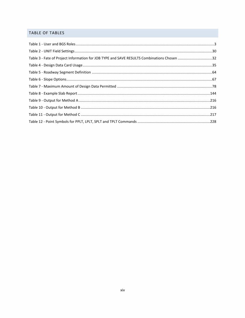
TABLE OF TABLES
Table 1 - User and BGS Roles ......................................................................................................................................... 3
Table 2 - UNIT Field Settings ........................................................................................................................................ 30
Table 3 - Fate of Project Information for JOB TYPE and SAVE RESULTS Combinations Chosen .................................. 32
Table 4 - Design Data Card Usage ................................................................................................................................ 35
Table 5 - Roadway Segment Definition ....................................................................................................................... 64
Table 6 - Slope Options ................................................................................................................................................ 67
Table 7 - Maximum Amount of Design Data Permitted .............................................................................................. 78
Table 8 - Example Slab Report ................................................................................................................................... 144
Table 9 - Output for Method A .................................................................................................................................. 216
Table 10 - Output for Method B ................................................................................................................................ 216
Table 11 - Output for Method C ................................................................................................................................ 217
Table 12 - Point Symbols for PPLT, LPLT, SPLT and TPLT Commands ........................................................................ 228

BGS v9.1 USER GUIDE (January 2016)
1
CHAPTER 1: INTRODUCTION
The Texas Department of Transportation (TxDOT) Bridge Geometry System (BGS) software was deployed in 2007
to replace the legacy TxDOT Roadway Design System (RDS) software as the department’s principal tool for the
geometric design of bridge structures.
RDS was used as a basis in the development of BGS. All non-bridge related program features were removed from
RDS and various enhancements were applied. The result of these changes is BGS, a "scaled down" implementation
of RDS that focuses on bridge geometrics.
An experienced RDS user will be able to begin using BGS immediately as BGS operates in the same way as RDS. The
BGS input data, output computations, reports and CAD plots are presented in the same manner as RDS when
applied to bridge geometric design although enhancements to the system have been made since RDS went into
the public domain.
PURPOSE OF THIS GUIDE
The BGS User Guide describes in detail how to use the BGS software to perform bridge geometric design and
serves as a reference document for coding input data sets.
ORGANIZATION OF THIS GUIDE
The BGS User Guide is organized in the following Chapters and Appendices:
CHAPTERS
Chapter 1: Introduction provides an introduction to BGS including the program’s history and relation to RDS, the
organization of this user guide and listing of other BGS related documentation.
Chapter 2: Getting Started targets the new user by providing an overview of how to begin using BGS. Subsequent
chapters provide additional detailed information about the various topics and concepts that are introduced in this
chapter.
Chapter 3: General Information and Terminology describes some aspects of BGS input forms which are common
to more than one form. Terminology, concepts and topics which apply to the system in general are also addressed.
Chapter 4: System Card describes the Card 1 - SYSTEM Card input in detail.
Chapter 5: Roadway Design Data describes how to use roadway design data to define the bridge roadway surface
in three dimensions.
Chapter 6: Command Structured Input – General Geometry, Chapter 7: Command Structured Input – Bridge
Geometry and Chapter 8: Command Structured Input – Plotting Command Structured Input give detailed
information on the input of general roadway geometry, bridge geometry and the plotting capabilities of BGS,
respectively. This includes information that describes each of the BGS commands that may be issued using
command structured input. The commands are organized and presented in groups of related functionality. In
particular, the bridge geometry commands are used to compute the geometric aspects of a bridge structure.
Chapter 9: Running BGS to Process the Input File describes how to invoke the BGS program and interface to
process the prepared BGS input data file.

BGS v9.1 USER GUIDE (January 2016)
2
Chapter 10: BGS Output describes the various output files generated by BGS.
Chapter 11: Using BGS Project Work Files is a place holder Chapter to be considered for a future edition of this
user guide. If provided it will describe how to use the optional BGS project work file program feature. This program
feature is normally only employed by experienced users on large complex bridge projects.
Chapter 12: Example Bridge Projects is a place holder Chapter to be considered for a future edition of this user
guide and is intended to include sample projects that describe how BGS is used to establish the geometric design
of bridge structures.
APPENDICES
Appendix A: BGS Input Forms provides short to images of each BGS input card.
This is a place holder Appendix to be considered for a future edition of this user guide.
Appendix B: Example BGS Log File provides an example BGS output Log file and includes a discussion of messages
found in the various sections of the file.
Appendix C: Example BGS Report Output provides samples of various BGS text output reports.
Appendix D: Example BGS Plot Output provides samples of various BGS output plots.
PROGRAM DESCRIPTION
BGS: A BRIDGE GEOMETRY SYSTEM
The Bridge Design System (BGS) is an integrated combination of over 300 computer processes (subroutines) that
can be used to perform geometric calculations and generate plots for a wide variety of bridge superstructure
types. The Roadway Design System (RDS) from which BGS is derived contained additional processes that gave RDS
geodetic control, earthwork design, and earthwork plotting functionality. These additional processes were not
retained in BGS because they are not needed for bridge geometrics.
BGS has been developed from RDS to provide bridge design engineers with a robust computational tool to model
bridge geometrics. BGS considers all pertinent geometric features of the roadway and bridge and to provide all
the reports and plots needed to design and detail bridge features of highways. Within certain limits the user may
arrange the computer processes (functions) in any combination or sequence, depending upon the size and scope
of the project, to achieve the desired results.
Although the system is quite comprehensive in scope, the user and BGS roles listed in Table 1 - User and BGS Roles
highlight the User-BGS partnership’s general capabilities.
Under the direction of the user via a simple text input file the system can perform a very broad range of functions
and generate a similarly broad range of text and graphic output. It is important to note that the user will not
employ the entire range of possible functions at any one time. The system performs any functions for which
sufficient and properly structured input has been provided by the user. Therefore, within certain limits functions
may be called in any sequence.
BGS v9.1 USER GUIDE (January 2016)
3
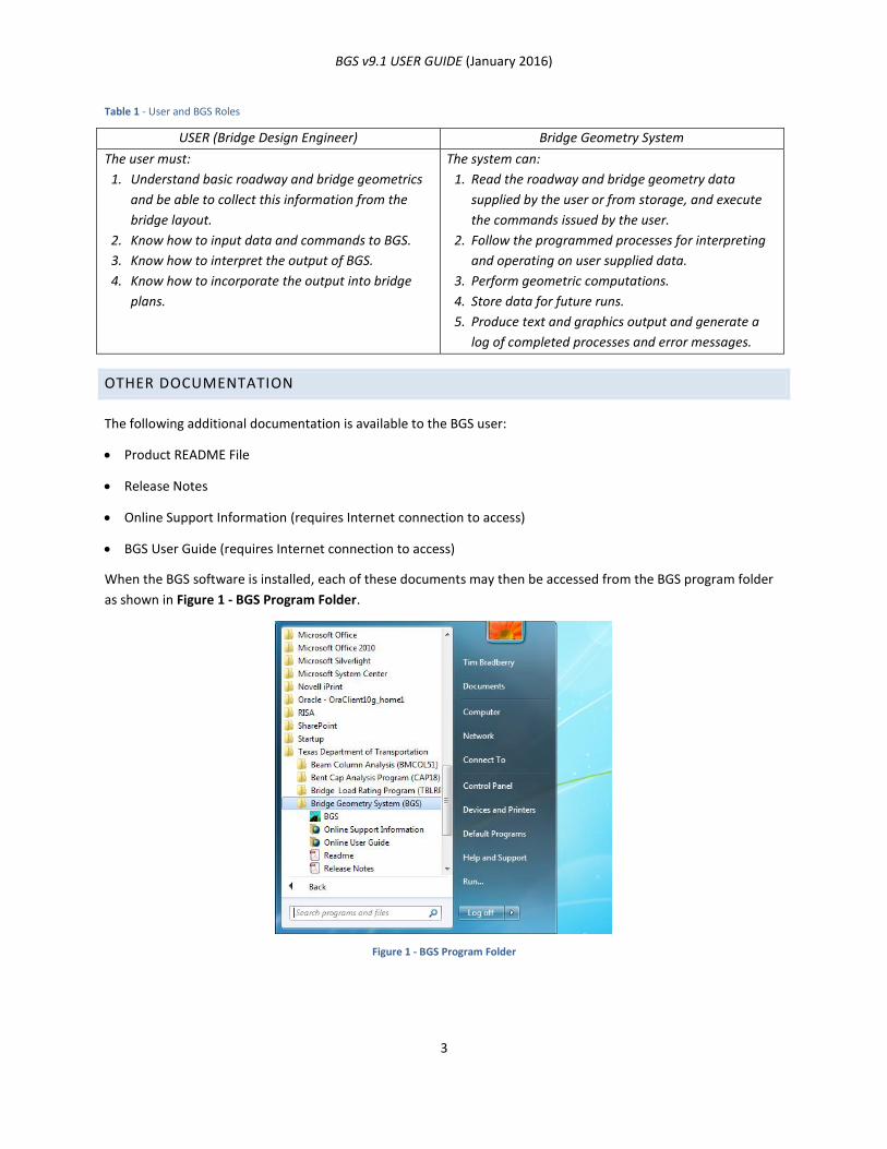
Table 1 - User and BGS Roles
USER (Bridge Design Engineer) Bridge Geometry System
The user must:
1. Understand basic roadway and bridge geometrics
and be able to collect this information from the
bridge layout.
2. Know how to input data and commands to BGS.
3. Know how to interpret the output of BGS.
4. Know how to incorporate the output into bridge
plans.
The system can:
1. Read the roadway and bridge geometry data
supplied by the user or from storage, and execute
the commands issued by the user.
2. Follow the programmed processes for interpreting
and operating on user supplied data.
3. Perform geometric computations.
4. Store data for future runs.
5. Produce text and graphics output and generate a
log of completed processes and error messages.
OTHER DOCUMENTATION
The following additional documentation is available to the BGS user:
Product README File
Release Notes
Online Support Information (requires Internet connection to access)
BGS User Guide (requires Internet connection to access)
When the BGS software is installed, each of these documents may then be accessed from the BGS program folder
as shown in Figure 1 - BGS Program Folder.
Figure 1 - BGS Program Folder

BGS v9.1 USER GUIDE (January 2016)
4
README FILE
The README file is included as part of the software installation. This document provides general information about
the software application and targets the IT professional who installs to software.
RELEASE NOTES
The Release Notes file is included as part of the software installation. This document details the changes that have
been applied to the software relative to previous releases.
ONLINE SUPPORT INFORMATION
The Support Information file is an Internet-based document that provides general support information. TxDOT may
update this document periodically, as needed, to convey up-to-date support information to the BGS user. The user
must have Internet access to download and view this file.
BGS USER GUIDE
The BGS User Guide (this document) provides the user with all the information needed to prepare input files and
run BGS. It is the successor to the Roadway Design System (RDS) User Manual, which when RDS was a critical tool
for both roadway and bridge design was maintained at the Deputy Executive Director level. The BGS User Guide is
maintained below the Division Section level (a much lower level). Therefore, to facilitate deployment of BGS the
BGS User Guide is not installed in the program folder but posted on TxDOT’s ftp server with an Internet link to it
placed in the program folder. This affords to OPR the opportunity to complete certain non-critical sections that are
not currently completed or to otherwise revise the document and repost it as needed.
BGS v9.1 USER GUIDE (January 2016)
5
CHAPTER 2: GETTING STARTED
BEFORE THE USER STARTS
Before running BGS to obtain text and plotting output, the user must: (1) (to obtain text output) have properly
installed the BGS application on a Windows-based computer, (2) (to in addition obtain plotting output) have
properly installed a compatible version of Microstation on the same computer; and should: (3) have in hand a
bridge layout (or at the least an alignment description) or other description of the alignment(s) and bridge
dimensions, and (4) have ASCII (text) editing software, preferably with cursor coordinate location (row and
column) capability, with which to prepare BGS input files. The file must be plain (ASCII) text free of any control
characters such as the hidden characters that permeate word processor files.
To aid in the input file creation and editing task, users are encouraged to Google (or use their favorite Internet
keyword search engine) on the keyword phrase “Programmer’s File Editor” (PFE) to locate and install this freeware
program. PFE displays the row and column coordinate location of the curser on the screen which is very useful for
the “card based” (a.k.a. “flat file”) input of fixed format FORTRAN based programs like BGS. As an alternative to
using PFE or comparable text editing software, the user may insert a ruler line as follows in the input file where
needed (this line may be left in the file or deleted prior to running the data through BGS):
$2345678901234567890123456789012345678901234567890123456789012345678901234567890
The bold characters are for illustrative purposes in this guide, making it easy to see that there are eight sets of ten
characters each. The flat file will not support bold font.
USING BGS
CREATING THE BGS INPUT FILE
BGS actions are requested and controlled through the use of user specified commands and design data. These
commands and design data must be coded into an ASCII (text) input file (flat file), each line of which contains a
single command or a set of design data. A line of input is also referred to herein as a card. This convenient term is
reflective of the punch card media once used for data input back when the parent program, RDS, was run on an
early generation mainframe computer. Just as was the case for punch cards in the early days of mainframe
automation, the input file must be prepared in advance of running BGS.
RUNNING BGS (PROCESSING THE BGS INPUT FILE)
An instance of the execution of the input data by BGS is often referred to as a “run.” When a run of BGS is initiated
the system operates on (i.e. processes) an input file (input data set) and generates text file output and, if
instructed to do so by the input cards, plots graphics to a MicroStation dgn file.
REVIEWING BGS OUTPUT
BGS text output is formatted as ASCII text and is best viewed in a text editor such as PFE or in a Word processor
using an equal-character-width font such as Courier. The output files have the following extensions (not all of
these output files will be produced in every run):
ls1—Mirror image of input data (optional) plus error and warning messages.

BGS v9.1 USER GUIDE (January 2016)
6
ls2—Formal output; results of roadway design and bridge command calculations. A majority of the bridge
geometry analysis results are in this file.
ls3—Diaphragm Report.
ls4—Alignment Plotting Data Report.
ls5—Summary Bent and Beam Reports.
ls6—Run Report.
Note: ls1 and ls2 will always be created but ls3 thru ls6 will exist and contain the listed information to the
extent that the elements of the reports are created by the BGS run. For example:
(1) If no diaphragms are used in the BGS run, no Diaphragm Report file will be generated. In this instance, file
ls3 will contain alignment plotting data, and the other reports will be shifted (Summary Bent and Beam Reports
would be in ls4, and Run Report in ls5); and
(2) If no diaphragms are used and no plot is requested, Summary Bent and Beam Reports will be in ls3, ls4
would contain the Run Report, and there would not be an ls5 or ls6 output file.
lgc—BGS Log File. This file captures all the messages that are streamed to the console during program
execution. [this log file will only be produced if the ‘-l’ (lower case L) flag is used (as it is, by default) in the
launch string (e.g., "C:\Program Files (x86)\TxDOT\BGS\bgs.exe" –l)]
pch— Punch File (if required). BGS can alter the input file in several ways; for example, it can convert from
English to metric units and vice versa. The Punch File is this altered input file.
dgn—Graphics File (if required). The MicroStation graphics file containing the plot created.
The following files are output in the special case of debugging. This should only be done when needing to provide
debug information for technical support (e.g., a run-time error has occurred) as running BGS in debug mode will
slow the BGS run and produce unnecessary files in an otherwise a normal and successful run. If this information is
needed, place ‘DBUG’ (without quotes) as the first four characters of the first line (i.e. on the Card 1 - SYSTEM
Card) of the ‘.dat’ input file to run BGS in debug mode.
lgf—BGS1 Log File. This file contains log messages generated while bridge geometry calculations are being
executed by the FORTRAN routines of the program.
dbc—BGS Debug File. This file contains debug messages generated during pre/post processing by the C+ part of
the program.
dbf—BGS1 Debug File. This file contains debug messages generated while bridge geometry calculations are
being executed by the FORTRAN routines of the program.
sbt—BGS1 Submit File. This file contains all lines of a temporary ‘submit’ file used to direct calculations in the
FORTRAN component of the program.
plt—BGS1 Plot File. This file contains all lines of a temporary ‘plot’ file created (when plotting is invoked) during
calculations.
BGS INPUT FILE
This section is a discussion of the most common commands used in BGS when modeling bridge geometry and how
the commands fit into the bridge design process. The section is divided into sub-sections based on the structure of
the example BGS input file listings shown at the end of this chapter. Each sub-section represents a function
BGS v9.1 USER GUIDE (January 2016)
7
performed by BGS and lists related commands needed to perform that function. The order of the sub-sections is
significant in that it represents the order in which commands are typically entered into the BGS data file. Each sub-
section, except in the case of the example input file listings, is divided into two parts: (1) a summary of the section
and general description of how applicable commands work together, and (2) an input-file snippet from a
representative bridge design example.
DEFINING ROADWAY GEOMETRY
INITIAL INPUT FILE SETUP
SUMMARY
For BGS to start processing an input file it must first “know” what processes are to be executed and where data is
going to come from—previously stored data file or new data cards to be included in the “deck”, as well as what to
call the run (heading). The user must get the system’s attention, so to speak. In the Roadway Design Systems
Manual, this was represented by the image shown in Figure 2 - May I Please Have Your Attention?
Figure 2 - May I Please Have Your Attention?
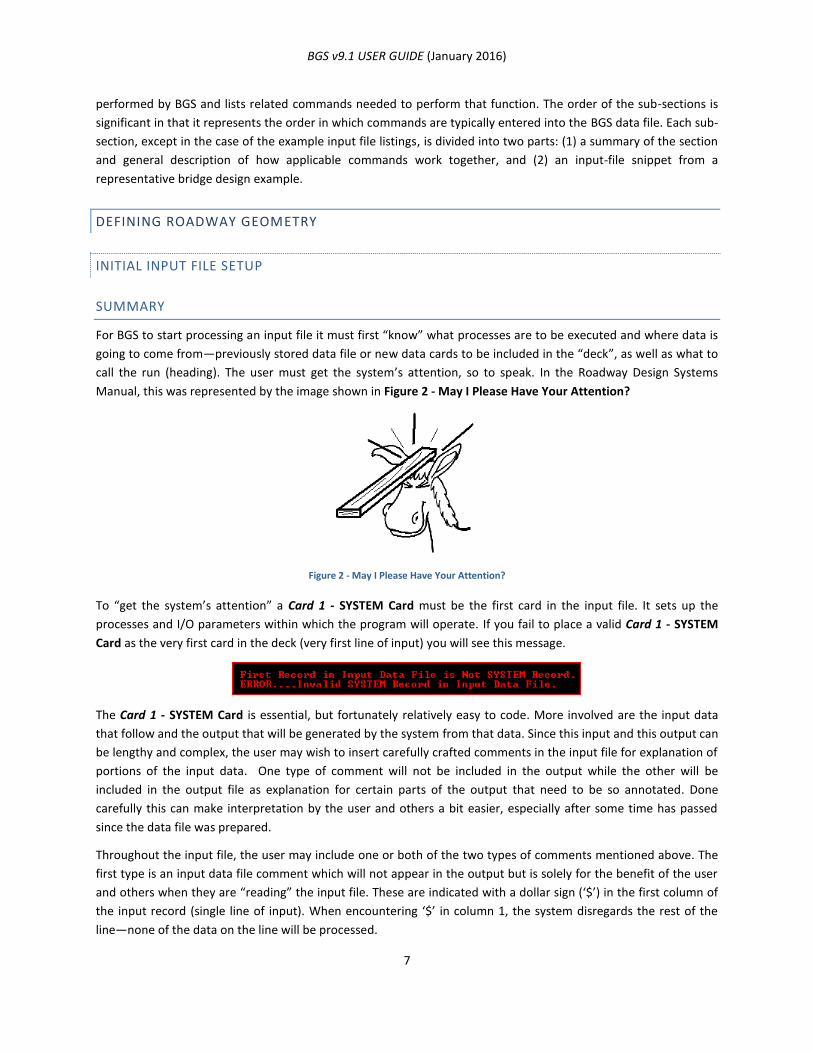
To “get the system’s attention” a Card 1 - SYSTEM Card must be the first card in the input file. It sets up the
processes and I/O parameters within which the program will operate. If you fail to place a valid Card 1 - SYSTEM
Card as the very first card in the deck (very first line of input) you will see this message.
The Card 1 - SYSTEM Card is essential, but fortunately relatively easy to code. More involved are the input data
that follow and the output that will be generated by the system from that data. Since this input and this output can
be lengthy and complex, the user may wish to insert carefully crafted comments in the input file for explanation of
portions of the input data. One type of comment will not be included in the output while the other will be
included in the output file as explanation for certain parts of the output that need to be so annotated. Done
carefully this can make interpretation by the user and others a bit easier, especially after some time has passed
since the data file was prepared.
Throughout the input file, the user may include one or both of the two types of comments mentioned above. The
first type is an input data file comment which will not appear in the output but is solely for the benefit of the user
and others when they are “reading” the input file. These are indicated with a dollar sign (‘$’) in the first column of
the input record (single line of input). When encountering ‘$’ in column 1, the system disregards the rest of the
line—none of the data on the line will be processed.
BGS v9.1 USER GUIDE (January 2016)
8
The second type of comment is one that will be included in the program output reports. These comments are
entered one or more Card 13 - CMNT Argument Input Scheme Card, which the system prints in the formal output.
Card 13 - CMNT Argument Input Scheme Card generated comments are useful for creating a clear, organized, and
annotated output file.
EXAMPLE INPUT FILE SNIPPET
The following is an example of the Card 1 - SYSTEM Card, Card 13 - CMNT Argument Input Scheme Card cards and
data file comments/annotations.
SYSTEM X X X NEW NOYESYESYESYES Example 1
$2345678901234567890123456789012345678901234567890123456789012345678901234567890
$ SYSTEM Example 1
$ Comments such as this one are inserted throughout this example input file.
$ These comments will describe all following cards up to the next comment.
RG CMNT These comments will appear in the output
RG CMNT file since they are the arguments to these
RG CMNT CMNT cards. Such comments must be confined
RG CMNT to columns 37 to 80.
Note that the second listed Card 1 - SYSTEM Card is “dollar signed” out. In BGS v8.1 the Processes to be Executed
(input cols 14 thru 24) and the Job Type (input col 28-30), Keep (store data, input col 31-33) and the three Data
Initialization fields (input col 34 thru 42) are not needed. This is because the three bridge related processes are the
only processes that are necessary—since roadway design has been removed from the system—so these otherwise
necessary processes were hard coded in v8.1. Also, the capability of storing parts of data from one run to be used
by another run when doing complex multi-bridge geometry, such as for interchanges, was disabled in v8.1. This has
all been reversed in BGS 9.1. So, when running an input file prepared for BGS v8.1 in BGS v9.1, the user must
provide the corresponding input data to the Card 1 - SYSTEM Card.
ESTABLISHING HORIZONTAL ALIGNMENT
SUMMARY
The first step in creating data for a bridge is to establish a reference roadway for the bridge. This is done by
defining,
1. A horizontal alignment.
2. A vertical alignment.
3. Roadway templates.
4. Optionally, roadway widening.
5. Optionally, roadway superelevation.
A horizontal alignment consists of a connected string of elements, usually straight line segments and circular arcs.
For some special cases (e.g., railroad bridges) it may also contain spiral elements.
Each entered point on the alignment has a station number. The user assigns the station number to the first point
on the alignment. BGS then assigns a station number to every other point on the alignment, depending on the
distance that point is from the first point. For example, in Sample 1 below station number 79+90.00 is assigned by
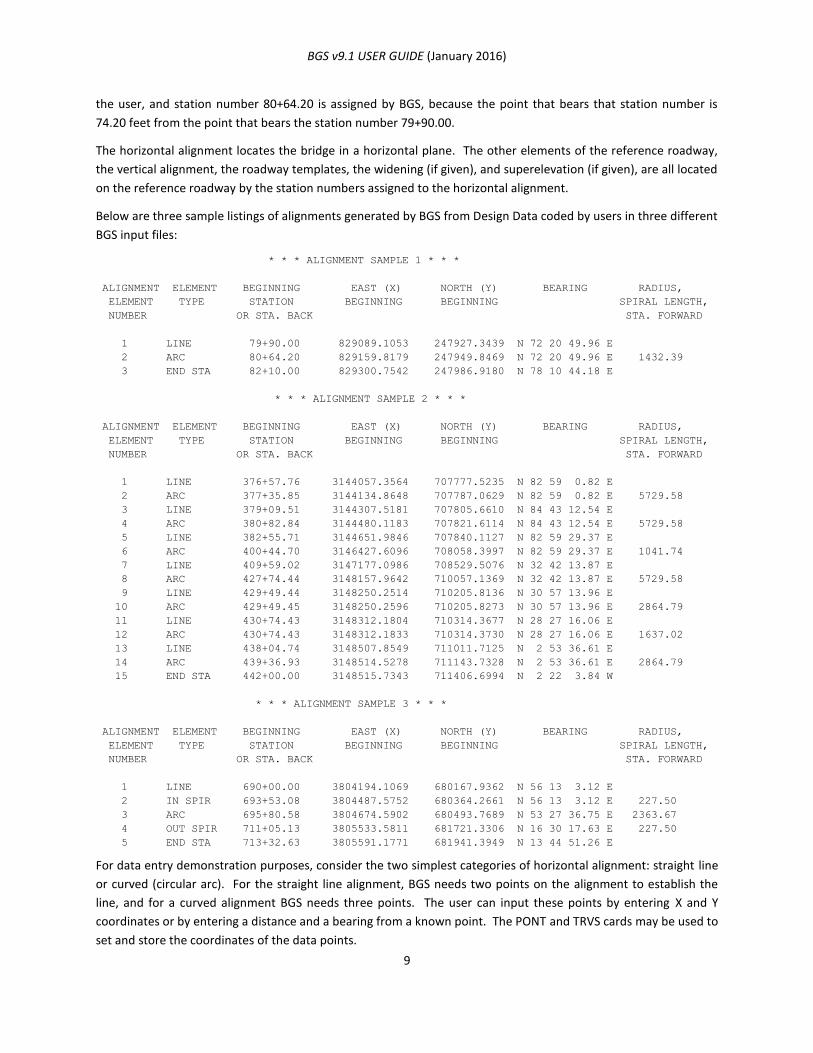
BGS v9.1 USER GUIDE (January 2016)
9
the user, and station number 80+64.20 is assigned by BGS, because the point that bears that station number is
74.20 feet from the point that bears the station number 79+90.00.
The horizontal alignment locates the bridge in a horizontal plane. The other elements of the reference roadway,
the vertical alignment, the roadway templates, the widening (if given), and superelevation (if given), are all located
on the reference roadway by the station numbers assigned to the horizontal alignment.
Below are three sample listings of alignments generated by BGS from Design Data coded by users in three different
BGS input files:
* * * ALIGNMENT SAMPLE 1 * * *
ALIGNMENT ELEMENT BEGINNING EAST (X) NORTH (Y) BEARING RADIUS,
ELEMENT TYPE STATION BEGINNING BEGINNING SPIRAL LENGTH,
NUMBER OR STA. BACK STA. FORWARD
1 LINE 79+90.00 829089.1053 247927.3439 N 72 20 49.96 E
2 ARC 80+64.20 829159.8179 247949.8469 N 72 20 49.96 E 1432.39
3 END STA 82+10.00 829300.7542 247986.9180 N 78 10 44.18 E
* * * ALIGNMENT SAMPLE 2 * * *
ALIGNMENT ELEMENT BEGINNING EAST (X) NORTH (Y) BEARING RADIUS,
ELEMENT TYPE STATION BEGINNING BEGINNING SPIRAL LENGTH,
NUMBER OR STA. BACK STA. FORWARD
1 LINE 376+57.76 3144057.3564 707777.5235 N 82 59 0.82 E
2 ARC 377+35.85 3144134.8648 707787.0629 N 82 59 0.82 E 5729.58
3 LINE 379+09.51 3144307.5181 707805.6610 N 84 43 12.54 E
4 ARC 380+82.84 3144480.1183 707821.6114 N 84 43 12.54 E 5729.58
5 LINE 382+55.71 3144651.9846 707840.1127 N 82 59 29.37 E
6 ARC 400+44.70 3146427.6096 708058.3997 N 82 59 29.37 E 1041.74
7 LINE 409+59.02 3147177.0986 708529.5076 N 32 42 13.87 E
8 ARC 427+74.44 3148157.9642 710057.1369 N 32 42 13.87 E 5729.58
9 LINE 429+49.44 3148250.2514 710205.8136 N 30 57 13.96 E
10 ARC 429+49.45 3148250.2596 710205.8273 N 30 57 13.96 E 2864.79
11 LINE 430+74.43 3148312.1804 710314.3677 N 28 27 16.06 E
12 ARC 430+74.43 3148312.1833 710314.3730 N 28 27 16.06 E 1637.02
13 LINE 438+04.74 3148507.8549 711011.7125 N 2 53 36.61 E
14 ARC 439+36.93 3148514.5278 711143.7328 N 2 53 36.61 E 2864.79
15 END STA 442+00.00 3148515.7343 711406.6994 N 2 22 3.84 W
* * * ALIGNMENT SAMPLE 3 * * *
ALIGNMENT ELEMENT BEGINNING EAST (X) NORTH (Y) BEARING RADIUS,
ELEMENT TYPE STATION BEGINNING BEGINNING SPIRAL LENGTH,
NUMBER OR STA. BACK STA. FORWARD
1 LINE 690+00.00 3804194.1069 680167.9362 N 56 13 3.12 E
2 IN SPIR 693+53.08 3804487.5752 680364.2661 N 56 13 3.12 E 227.50
3 ARC 695+80.58 3804674.5902 680493.7689 N 53 27 36.75 E 2363.67
4 OUT SPIR 711+05.13 3805533.5811 681721.3306 N 16 30 17.63 E 227.50
5 END STA 713+32.63 3805591.1771 681941.3949 N 13 44 51.26 E
For data entry demonstration purposes, consider the two simplest categories of horizontal alignment: straight line
or curved (circular arc). For the straight line alignment, BGS needs two points on the alignment to establish the
line, and for a curved alignment BGS needs three points. The user can input these points by entering X and Y
coordinates or by entering a distance and a bearing from a known point. The PONT and TRVS cards may be used to
set and store the coordinates of the data points.
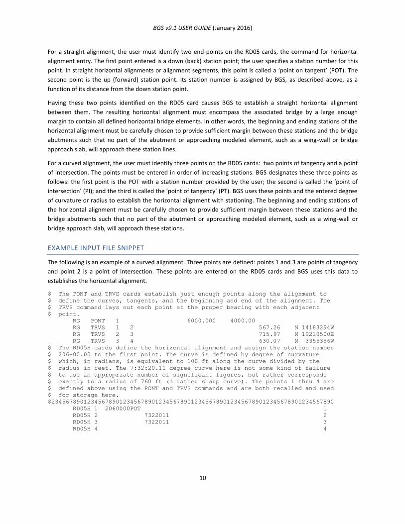
BGS v9.1 USER GUIDE (January 2016)
10
For a straight alignment, the user must identify two end-points on the RD05 cards, the command for horizontal
alignment entry. The first point entered is a down (back) station point; the user specifies a station number for this
point. In straight horizontal alignments or alignment segments, this point is called a ‘point on tangent’ (POT). The
second point is the up (forward) station point. Its station number is assigned by BGS, as described above, as a
function of its distance from the down station point.
Having these two points identified on the RD05 card causes BGS to establish a straight horizontal alignment
between them. The resulting horizontal alignment must encompass the associated bridge by a large enough
margin to contain all defined horizontal bridge elements. In other words, the beginning and ending stations of the
horizontal alignment must be carefully chosen to provide sufficient margin between these stations and the bridge
abutments such that no part of the abutment or approaching modeled element, such as a wing-wall or bridge
approach slab, will approach these station lines.
For a curved alignment, the user must identify three points on the RD05 cards: two points of tangency and a point
of intersection. The points must be entered in order of increasing stations. BGS designates these three points as
follows: the first point is the POT with a station number provided by the user; the second is called the ‘point of
intersection’ (PI); and the third is called the ‘point of tangency’ (PT). BGS uses these points and the entered degree
of curvature or radius to establish the horizontal alignment with stationing. The beginning and ending stations of
the horizontal alignment must be carefully chosen to provide sufficient margin between these stations and the
bridge abutments such that no part of the abutment or approaching modeled element, such as a wing-wall or
bridge approach slab, will approach these stations.
EXAMPLE INPUT FILE SNIPPET
The following is an example of a curved alignment. Three points are defined: points 1 and 3 are points of tangency
and point 2 is a point of intersection. These points are entered on the RD05 cards and BGS uses this data to
establishes the horizontal alignment.
$ The PONT and TRVS cards establish just enough points along the alignment to
$ define the curves, tangents, and the beginning and end of the alignment. The
$ TRVS command lays out each point at the proper bearing with each adjacent
$ point.
RG PONT 1 6000.000 4000.00
RG TRVS 1 2 567.26 N 14183294W
RG TRVS 2 3 715.97 N 19210500E
RG TRVS 3 4 630.07 N 3355356W
$ The RD05H cards define the horizontal alignment and assign the station number
$ 206+00.00 to the first point. The curve is defined by degree of curvature
$ which, in radians, is equivalent to 100 ft along the curve divided by the
$ radius in feet. The 7:32:20.11 degree curve here is not some kind of failure
$ to use an appropriate number of significant figures, but rather corresponds
$ exactly to a radius of 760 ft (a rather sharp curve). The points 1 thru 4 are
$ defined above using the PONT and TRVS commands and are both recalled and used
$ for storage here.
$2345678901234567890123456789012345678901234567890123456789012345678901234567890
RD05H 1 2060000POT 1
RD05H 2 7322011 2
RD05H 3 7322011 3
RD05H 4 4
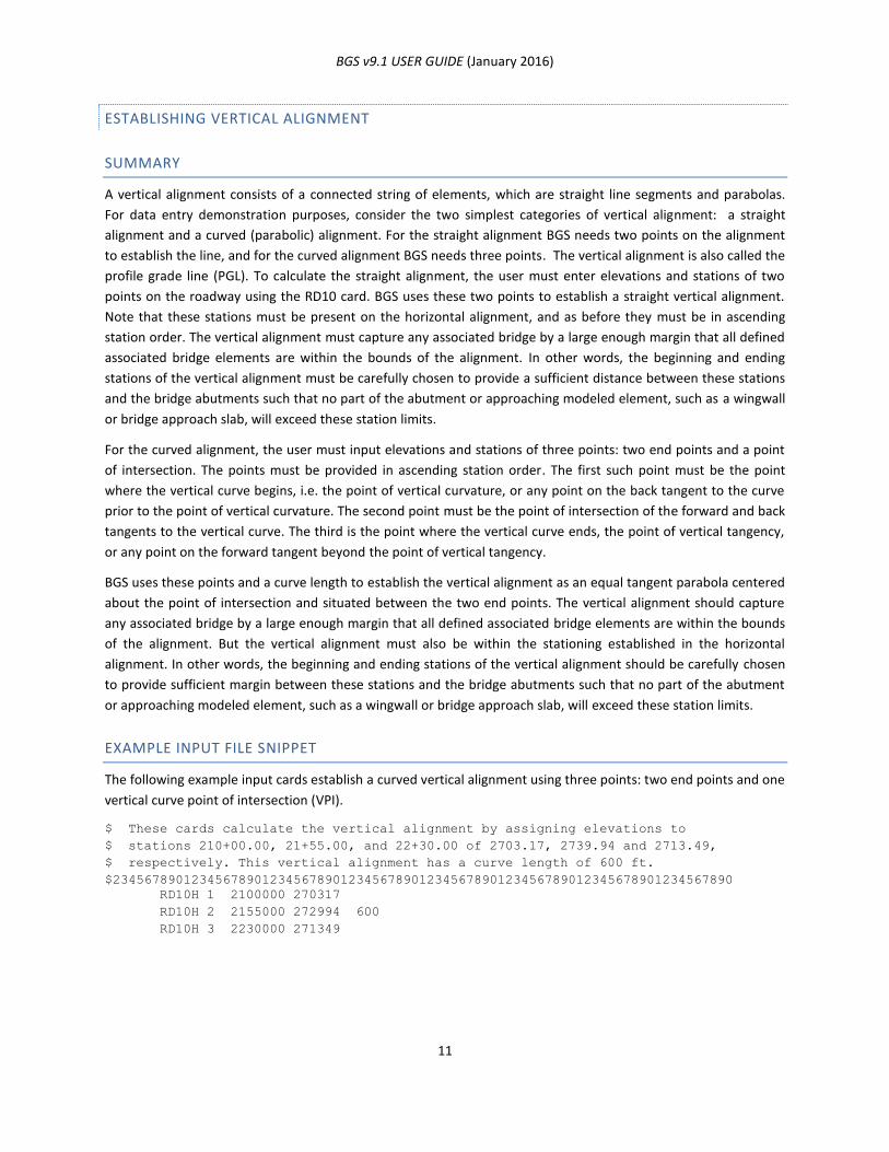
BGS v9.1 USER GUIDE (January 2016)
11
ESTABLISHING VERTICAL ALIGNMENT
SUMMARY
A vertical alignment consists of a connected string of elements, which are straight line segments and parabolas.
For data entry demonstration purposes, consider the two simplest categories of vertical alignment: a straight
alignment and a curved (parabolic) alignment. For the straight alignment BGS needs two points on the alignment
to establish the line, and for the curved alignment BGS needs three points. The vertical alignment is also called the
profile grade line (PGL). To calculate the straight alignment, the user must enter elevations and stations of two
points on the roadway using the RD10 card. BGS uses these two points to establish a straight vertical alignment.
Note that these stations must be present on the horizontal alignment, and as before they must be in ascending
station order. The vertical alignment must capture any associated bridge by a large enough margin that all defined
associated bridge elements are within the bounds of the alignment. In other words, the beginning and ending
stations of the vertical alignment must be carefully chosen to provide a sufficient distance between these stations
and the bridge abutments such that no part of the abutment or approaching modeled element, such as a wingwall
or bridge approach slab, will exceed these station limits.
For the curved alignment, the user must input elevations and stations of three points: two end points and a point
of intersection. The points must be provided in ascending station order. The first such point must be the point
where the vertical curve begins, i.e. the point of vertical curvature, or any point on the back tangent to the curve
prior to the point of vertical curvature. The second point must be the point of intersection of the forward and back
tangents to the vertical curve. The third is the point where the vertical curve ends, the point of vertical tangency,
or any point on the forward tangent beyond the point of vertical tangency.
BGS uses these points and a curve length to establish the vertical alignment as an equal tangent parabola centered
about the point of intersection and situated between the two end points. The vertical alignment should capture
any associated bridge by a large enough margin that all defined associated bridge elements are within the bounds
of the alignment. But the vertical alignment must also be within the stationing established in the horizontal
alignment. In other words, the beginning and ending stations of the vertical alignment should be carefully chosen
to provide sufficient margin between these stations and the bridge abutments such that no part of the abutment
or approaching modeled element, such as a wingwall or bridge approach slab, will exceed these station limits.
EXAMPLE INPUT FILE SNIPPET
The following example input cards establish a curved vertical alignment using three points: two end points and one
vertical curve point of intersection (VPI).
$ These cards calculate the vertical alignment by assigning elevations to
$ stations 210+00.00, 21+55.00, and 22+30.00 of 2703.17, 2739.94 and 2713.49,
$ respectively. This vertical alignment has a curve length of 600 ft.
$2345678901234567890123456789012345678901234567890123456789012345678901234567890
RD10H 1 2100000 270317
RD10H 2 2155000 272994 600
RD10H 3 2230000 271349
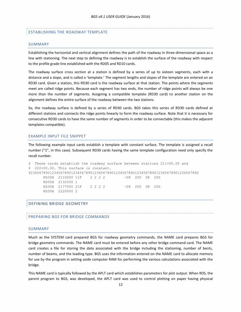
BGS v9.1 USER GUIDE (January 2016)
12
ESTABLISHING THE ROADWAY TEMPLATE
SUMMARY
Establishing the horizontal and vertical alignment defines the path of the roadway in three-dimensional space as a
line with stationing. The next step to defining the roadway is to establish the surface of the roadway with respect
to the profile grade line established with the RD05 and RD10 cards.
The roadway surface cross section at a station is defined by a series of up to sixteen segments, each with a
distance and a slope, and is called a ‘template.’ The segment lengths and slopes of the template are entered on an
RD30 card. Given a station, this RD30 card is the roadway surface at that station. The points where the segments
meet are called ridge points. Because each segment has two ends, the number of ridge points will always be one
more than the number of segments. Assigning a compatible template (RD30 card) to another station on the
alignment defines the entire surface of the roadway between the two stations.
So, the roadway surface is defined by a series of RD30 cards. BGS takes this series of RD30 cards defined at
different stations and connects the ridge points linearly to form the roadway surface. Note that it is necessary for
consecutive RD30 cards to have the same number of segments in order to be connectable (this makes the adjacent
templates compatible).
EXAMPLE INPUT FILE SNIPPET
The following example input cards establish a template with constant surface. The template is assigned a recall
number (“1”, in this case). Subsequent RD30 cards having the same template configuration need only specify the
recall number.
$ These cards establish the roadway surface between stations 211+00.00 and
$ 222+00.00. This surface is constant.
$2345678901234567890123456789012345678901234567890123456789012345678901234567890
RD30H 2110000 11F 2 2 2 2 -08 200 08 200
RD30H 2132500 1
RD30H 2177500 21F 2 2 2 2 -08 200 08 200
RD30H 2220000 2
DEFINING BRIDGE GEOMETRY
PREPARING BGS FOR BRIDGE COMMANDS
SUMMARY
Much as the SYSTEM card prepared BGS for roadway geometry commands, the NAME card prepares BGS for
bridge geometry commands. The NAME card must be entered before any other bridge command card. The NAME
card creates a file for storing the data associated with the bridge including the stationing, number of bents,
number of beams, and the loading type. BGS uses the information entered on the NAME card to allocate memory
for use by the program in setting aside computer RAM for performing the various calculations associated with the
bridge.
This NAME card is typically followed by the APLT card which establishes parameters for plot output. When RDS, the
parent program to BGS, was developed, the APLT card was used to control plotting on paper having physical
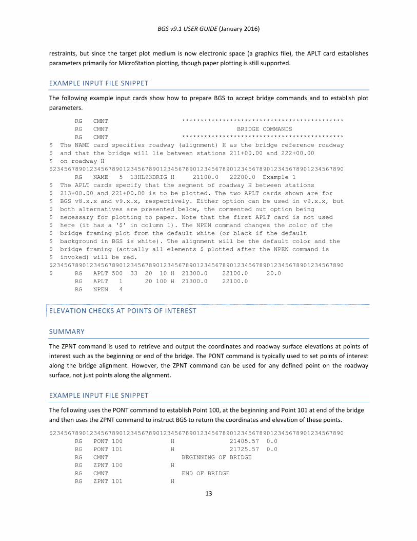
BGS v9.1 USER GUIDE (January 2016)
13
restraints, but since the target plot medium is now electronic space (a graphics file), the APLT card establishes
parameters primarily for MicroStation plotting, though paper plotting is still supported.
EXAMPLE INPUT FILE SNIPPET
The following example input cards show how to prepare BGS to accept bridge commands and to establish plot
parameters.
RG CMNT ********************************************
RG CMNT BRIDGE COMMANDS
RG CMNT ********************************************
$ The NAME card specifies roadway (alignment) H as the bridge reference roadway
$ and that the bridge will lie between stations 211+00.00 and 222+00.00
$ on roadway H
$2345678901234567890123456789012345678901234567890123456789012345678901234567890
RG NAME 5 13HL93BRIG H 21100.0 22200.0 Example 1
$ The APLT cards specify that the segment of roadway H between stations
$ 213+00.00 and 221+00.00 is to be plotted. The two APLT cards shown are for
$ BGS v8.x.x and v9.x.x, respectively. Either option can be used in v9.x.x, but
$ both alternatives are presented below, the commented out option being
$ necessary for plotting to paper. Note that the first APLT card is not used
$ here (it has a '$' in column 1). The NPEN command changes the color of the
$ bridge framing plot from the default white (or black if the default
$ background in BGS is white). The alignment will be the default color and the
$ bridge framing (actually all elements $ plotted after the NPEN command is
$ invoked) will be red.
$2345678901234567890123456789012345678901234567890123456789012345678901234567890
$ RG APLT 500 33 20 10 H 21300.0 22100.0 20.0
RG APLT 1 20 100 H 21300.0 22100.0
RG NPEN 4
ELEVATION CHECKS AT POINTS OF INTEREST
SUMMARY
The ZPNT command is used to retrieve and output the coordinates and roadway surface elevations at points of
interest such as the beginning or end of the bridge. The PONT command is typically used to set points of interest
along the bridge alignment. However, the ZPNT command can be used for any defined point on the roadway
surface, not just points along the alignment.
EXAMPLE INPUT FILE SNIPPET
The following uses the PONT command to establish Point 100, at the beginning and Point 101 at end of the bridge
and then uses the ZPNT command to instruct BGS to return the coordinates and elevation of these points.
$2345678901234567890123456789012345678901234567890123456789012345678901234567890
RG PONT 100 H 21405.57 0.0
RG PONT 101 H 21725.57 0.0
RG CMNT BEGINNING OF BRIDGE
RG ZPNT 100 H
RG CMNT END OF BRIDGE
RG ZPNT 101 H
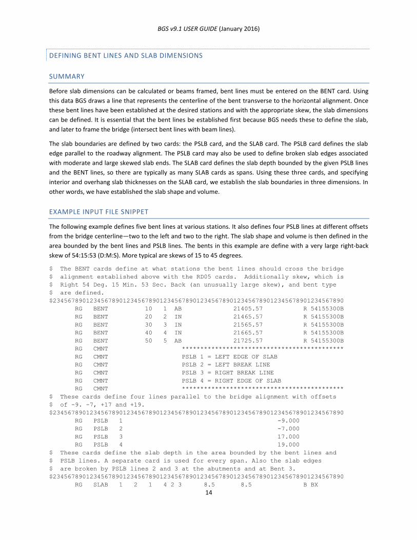
BGS v9.1 USER GUIDE (January 2016)
14
DEFINING BENT LINES AND SLAB DIMENSIONS
SUMMARY
Before slab dimensions can be calculated or beams framed, bent lines must be entered on the BENT card. Using
this data BGS draws a line that represents the centerline of the bent transverse to the horizontal alignment. Once
these bent lines have been established at the desired stations and with the appropriate skew, the slab dimensions
can be defined. It is essential that the bent lines be established first because BGS needs these to define the slab,
and later to frame the bridge (intersect bent lines with beam lines).
The slab boundaries are defined by two cards: the PSLB card, and the SLAB card. The PSLB card defines the slab
edge parallel to the roadway alignment. The PSLB card may also be used to define broken slab edges associated
with moderate and large skewed slab ends. The SLAB card defines the slab depth bounded by the given PSLB lines
and the BENT lines, so there are typically as many SLAB cards as spans. Using these three cards, and specifying
interior and overhang slab thicknesses on the SLAB card, we establish the slab boundaries in three dimensions. In
other words, we have established the slab shape and volume.
EXAMPLE INPUT FILE SNIPPET
The following example defines five bent lines at various stations. It also defines four PSLB lines at different offsets
from the bridge centerline—two to the left and two to the right. The slab shape and volume is then defined in the
area bounded by the bent lines and PSLB lines. The bents in this example are define with a very large right-back
skew of 54:15:53 (D:M:S). More typical are skews of 15 to 45 degrees.
$ The BENT cards define at what stations the bent lines should cross the bridge
$ alignment established above with the RD05 cards. Additionally skew, which is
$ Right 54 Deg. 15 Min. 53 Sec. Back (an unusually large skew), and bent type
$ are defined.
$2345678901234567890123456789012345678901234567890123456789012345678901234567890
RG BENT 10 1 AB 21405.57 R 54155300B
RG BENT 20 2 IN 21465.57 R 54155300B
RG BENT 30 3 IN 21565.57 R 54155300B
RG BENT 40 4 IN 21665.57 R 54155300B
RG BENT 50 5 AB 21725.57 R 54155300B
RG CMNT ********************************************
RG CMNT PSLB 1 = LEFT EDGE OF SLAB
RG CMNT PSLB 2 = LEFT BREAK LINE
RG CMNT PSLB 3 = RIGHT BREAK LINE
RG CMNT PSLB 4 = RIGHT EDGE OF SLAB
RG CMNT ********************************************
$ These cards define four lines parallel to the bridge alignment with offsets
$ of -9. -7, +17 and +19.
$2345678901234567890123456789012345678901234567890123456789012345678901234567890
RG PSLB 1 -9.000
RG PSLB 2 -7.000
RG PSLB 3 17.000
RG PSLB 4 19.000
$ These cards define the slab depth in the area bounded by the bent lines and
$ PSLB lines. A separate card is used for every span. Also the slab edges
$ are broken by PSLB lines 2 and 3 at the abutments and at Bent 3.
$2345678901234567890123456789012345678901234567890123456789012345678901234567890
RG SLAB 1 2 1 4 2 3 8.5 8.5 B BX
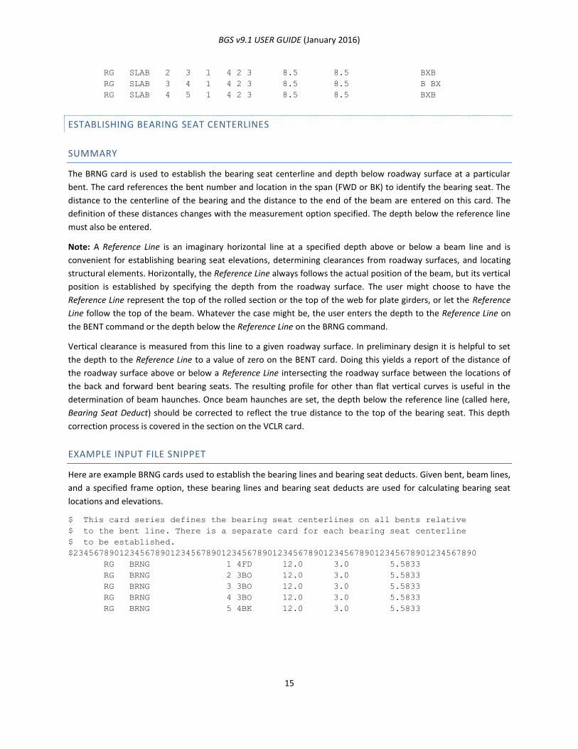
BGS v9.1 USER GUIDE (January 2016)
15
RG SLAB 2 3 1 4 2 3 8.5 8.5 BXB
RG SLAB 3 4 1 4 2 3 8.5 8.5 B BX
RG SLAB 4 5 1 4 2 3 8.5 8.5 BXB
ESTABLISHING BEARING SEAT CENTERLINES
SUMMARY
The BRNG card is used to establish the bearing seat centerline and depth below roadway surface at a particular
bent. The card references the bent number and location in the span (FWD or BK) to identify the bearing seat. The
distance to the centerline of the bearing and the distance to the end of the beam are entered on this card. The
definition of these distances changes with the measurement option specified. The depth below the reference line
must also be entered.
Note: A Reference Line is an imaginary horizontal line at a specified depth above or below a beam line and is
convenient for establishing bearing seat elevations, determining clearances from roadway surfaces, and locating
structural elements. Horizontally, the Reference Line always follows the actual position of the beam, but its vertical
position is established by specifying the depth from the roadway surface. The user might choose to have the
Reference Line represent the top of the rolled section or the top of the web for plate girders, or let the Reference
Line follow the top of the beam. Whatever the case might be, the user enters the depth to the Reference Line on
the BENT command or the depth below the Reference Line on the BRNG command.
Vertical clearance is measured from this line to a given roadway surface. In preliminary design it is helpful to set
the depth to the Reference Line to a value of zero on the BENT card. Doing this yields a report of the distance of
the roadway surface above or below a Reference Line intersecting the roadway surface between the locations of
the back and forward bent bearing seats. The resulting profile for other than flat vertical curves is useful in the
determination of beam haunches. Once beam haunches are set, the depth below the reference line (called here,
Bearing Seat Deduct) should be corrected to reflect the true distance to the top of the bearing seat. This depth
correction process is covered in the section on the VCLR card.
EXAMPLE INPUT FILE SNIPPET
Here are example BRNG cards used to establish the bearing lines and bearing seat deducts. Given bent, beam lines,
and a specified frame option, these bearing lines and bearing seat deducts are used for calculating bearing seat
locations and elevations.
$ This card series defines the bearing seat centerlines on all bents relative
$ to the bent line. There is a separate card for each bearing seat centerline
$ to be established.
$2345678901234567890123456789012345678901234567890123456789012345678901234567890
RG BRNG 1 4FD 12.0 3.0 5.5833
RG BRNG 2 3BO 12.0 3.0 5.5833
RG BRNG 3 3BO 12.0 3.0 5.5833
RG BRNG 4 3BO 12.0 3.0 5.5833
RG BRNG 5 4BK 12.0 3.0 5.5833
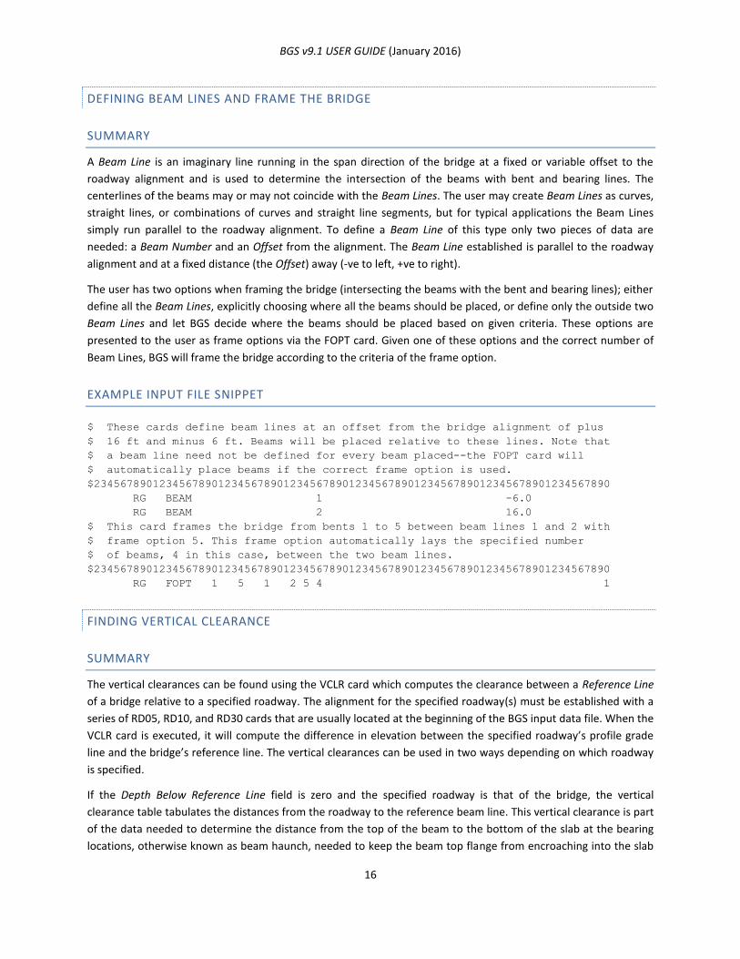
BGS v9.1 USER GUIDE (January 2016)
16
DEFINING BEAM LINES AND FRAME THE BRIDGE
SUMMARY
A Beam Line is an imaginary line running in the span direction of the bridge at a fixed or variable offset to the
roadway alignment and is used to determine the intersection of the beams with bent and bearing lines. The
centerlines of the beams may or may not coincide with the Beam Lines. The user may create Beam Lines as curves,
straight lines, or combinations of curves and straight line segments, but for typical applications the Beam Lines
simply run parallel to the roadway alignment. To define a Beam Line of this type only two pieces of data are
needed: a Beam Number and an Offset from the alignment. The Beam Line established is parallel to the roadway
alignment and at a fixed distance (the Offset) away (-ve to left, +ve to right).
The user has two options when framing the bridge (intersecting the beams with the bent and bearing lines); either
define all the Beam Lines, explicitly choosing where all the beams should be placed, or define only the outside two
Beam Lines and let BGS decide where the beams should be placed based on given criteria. These options are
presented to the user as frame options via the FOPT card. Given one of these options and the correct number of
Beam Lines, BGS will frame the bridge according to the criteria of the frame option.
EXAMPLE INPUT FILE SNIPPET
$ These cards define beam lines at an offset from the bridge alignment of plus
$ 16 ft and minus 6 ft. Beams will be placed relative to these lines. Note that
$ a beam line need not be defined for every beam placed--the FOPT card will
$ automatically place beams if the correct frame option is used.
$2345678901234567890123456789012345678901234567890123456789012345678901234567890
RG BEAM 1 -6.0
RG BEAM 2 16.0
$ This card frames the bridge from bents 1 to 5 between beam lines 1 and 2 with
$ frame option 5. This frame option automatically lays the specified number
$ of beams, 4 in this case, between the two beam lines.
$2345678901234567890123456789012345678901234567890123456789012345678901234567890
RG FOPT 1 5 1 2 5 4 1
FINDING VERTICAL CLEARANCE
SUMMARY
The vertical clearances can be found using the VCLR card which computes the clearance between a Reference Line
of a bridge relative to a specified roadway. The alignment for the specified roadway(s) must be established with a
series of RD05, RD10, and RD30 cards that are usually located at the beginning of the BGS input data file. When the
VCLR card is executed, it will compute the difference in elevation between the specified roadway’s profile grade
line and the bridge’s reference line. The vertical clearances can be used in two ways depending on which roadway
is specified.
If the Depth Below Reference Line field is zero and the specified roadway is that of the bridge, the vertical
clearance table tabulates the distances from the roadway to the reference beam line. This vertical clearance is part
of the data needed to determine the distance from the top of the beam to the bottom of the slab at the bearing
locations, otherwise known as beam haunch, needed to keep the beam top flange from encroaching into the slab
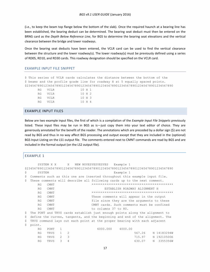
BGS v9.1 USER GUIDE (January 2016)
17
(i.e., to keep the beam top flange below the bottom of the slab). Once the required haunch at a bearing line has
been established, the bearing deduct can be determined. The bearing seat deduct must then be entered on the
BRNG card as the Depth Below Reference Line, for BGS to determine the bearing seat elevations and the vertical
clearance between the bridge and lower roadways.
Once the bearing seat deducts have been entered, the VCLR card can be used to find the vertical clearance
between the structure and the lower roadway(s). The lower roadway(s) must be previously defined using a series
of RD05, RD10, and RD30 cards. This roadway designation should be specified on the VCLR card.
EXAMPLE INPUT FILE SNIPPET
$ This series of VCLR cards calculates the distance between the bottom of the
$ beams and the profile grade line for roadway H at 5 equally spaced points.
$2345678901234567890123456789012345678901234567890123456789012345678901234567890
RG VCLR 10 H 1
RG VCLR 10 H 2
RG VCLR 10 H 3
RG VCLR 10 H 4
EXAMPLE INPUT FILES
Below are two example input files, the first of which is a compilation of the Example Input File Snippets previously
listed. These input files may be run in BGS as is—just copy them into your text editor of choice. They are
generously annotated for the benefit of the reader. The annotations which are preceded by a dollar sign ($) are not
read by BGS and thus in no way affect BGS processing and output except that they are included in the (optional)
BGS Input Listing on the LS1 output file. The comments entered next to CMNT commands are read by BGS and are
included in the formal output (on the LS2 output file).
EXAMPLE 1
SYSTEM X X X NEW NOYESYESYESYES Example 1
$2345678901234567890123456789012345678901234567890123456789012345678901234567890
$ SYSTEM Example 1
$ Comments such as this one are inserted throughout this example input file.
$ These comments will describe all following cards up to the next comment.
RG CMNT ********************************************
RG CMNT ESTABLISH ROADWAY ALIGNMENT H
RG CMNT ********************************************
RG CMNT These comments will appear in the output
RG CMNT file since they are the arguments to these
RG CMNT CMNT cards. Such comments must be confined
RG CMNT to columns 37 to 80.
$ The PONT and TRVS cards establish just enough points along the alignment to
$ define the curves, tangents, and the beginning and end of the alignment. The
$ TRVS command lays out each point at the proper bearing with each adjacent
$ point.
RG PONT 1 6000.000 4000.00
RG TRVS 1 2 567.26 N 14183294W
RG TRVS 2 3 715.97 N 19210500E
RG TRVS 3 4 630.07 N 3355356W
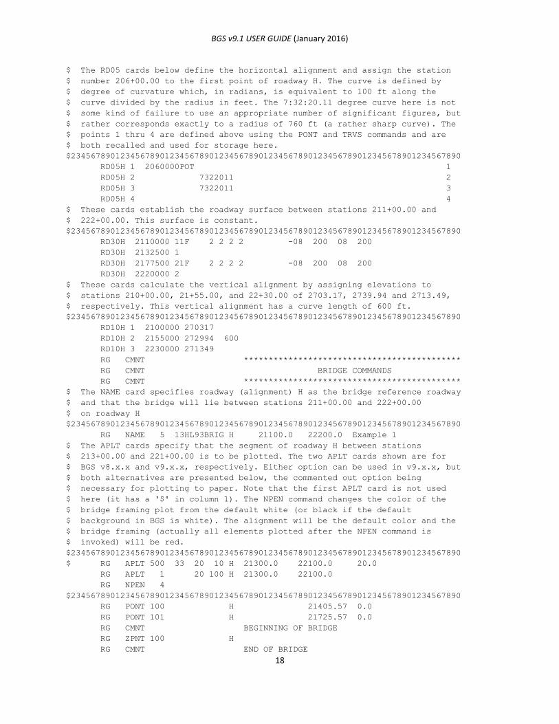
BGS v9.1 USER GUIDE (January 2016)
18
$ The RD05 cards below define the horizontal alignment and assign the station
$ number 206+00.00 to the first point of roadway H. The curve is defined by
$ degree of curvature which, in radians, is equivalent to 100 ft along the
$ curve divided by the radius in feet. The 7:32:20.11 degree curve here is not
$ some kind of failure to use an appropriate number of significant figures, but
$ rather corresponds exactly to a radius of 760 ft (a rather sharp curve). The
$ points 1 thru 4 are defined above using the PONT and TRVS commands and are
$ both recalled and used for storage here.
$2345678901234567890123456789012345678901234567890123456789012345678901234567890
RD05H 1 2060000POT 1
RD05H 2 7322011 2
RD05H 3 7322011 3
RD05H 4 4
$ These cards establish the roadway surface between stations 211+00.00 and
$ 222+00.00. This surface is constant.
$2345678901234567890123456789012345678901234567890123456789012345678901234567890
RD30H 2110000 11F 2 2 2 2 -08 200 08 200
RD30H 2132500 1
RD30H 2177500 21F 2 2 2 2 -08 200 08 200
RD30H 2220000 2
$ These cards calculate the vertical alignment by assigning elevations to
$ stations 210+00.00, 21+55.00, and 22+30.00 of 2703.17, 2739.94 and 2713.49,
$ respectively. This vertical alignment has a curve length of 600 ft.
$2345678901234567890123456789012345678901234567890123456789012345678901234567890
RD10H 1 2100000 270317
RD10H 2 2155000 272994 600
RD10H 3 2230000 271349
RG CMNT ********************************************
RG CMNT BRIDGE COMMANDS
RG CMNT ********************************************
$ The NAME card specifies roadway (alignment) H as the bridge reference roadway
$ and that the bridge will lie between stations 211+00.00 and 222+00.00
$ on roadway H
$2345678901234567890123456789012345678901234567890123456789012345678901234567890
RG NAME 5 13HL93BRIG H 21100.0 22200.0 Example 1
$ The APLT cards specify that the segment of roadway H between stations
$ 213+00.00 and 221+00.00 is to be plotted. The two APLT cards shown are for
$ BGS v8.x.x and v9.x.x, respectively. Either option can be used in v9.x.x, but
$ both alternatives are presented below, the commented out option being
$ necessary for plotting to paper. Note that the first APLT card is not used
$ here (it has a '$' in column 1). The NPEN command changes the color of the
$ bridge framing plot from the default white (or black if the default
$ background in BGS is white). The alignment will be the default color and the
$ bridge framing (actually all elements plotted after the NPEN command is
$ invoked) will be red.
$2345678901234567890123456789012345678901234567890123456789012345678901234567890
$ RG APLT 500 33 20 10 H 21300.0 22100.0 20.0
RG APLT 1 20 100 H 21300.0 22100.0
RG NPEN 4
$2345678901234567890123456789012345678901234567890123456789012345678901234567890
RG PONT 100 H 21405.57 0.0
RG PONT 101 H 21725.57 0.0
RG CMNT BEGINNING OF BRIDGE
RG ZPNT 100 H
RG CMNT END OF BRIDGE
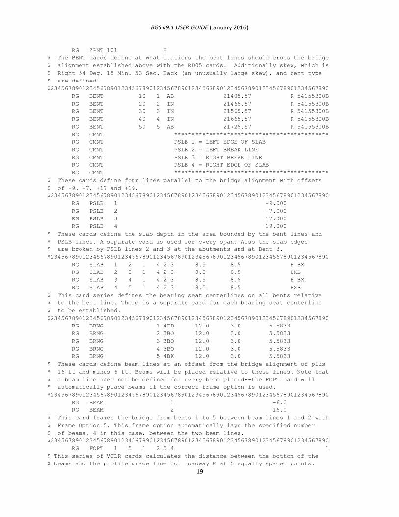
BGS v9.1 USER GUIDE (January 2016)
19
RG ZPNT 101 H
$ The BENT cards define at what stations the bent lines should cross the bridge
$ alignment established above with the RD05 cards. Additionally skew, which is
$ Right 54 Deg. 15 Min. 53 Sec. Back (an unusually large skew), and bent type
$ are defined.
$2345678901234567890123456789012345678901234567890123456789012345678901234567890
RG BENT 10 1 AB 21405.57 R 54155300B
RG BENT 20 2 IN 21465.57 R 54155300B
RG BENT 30 3 IN 21565.57 R 54155300B
RG BENT 40 4 IN 21665.57 R 54155300B
RG BENT 50 5 AB 21725.57 R 54155300B
RG CMNT ********************************************
RG CMNT PSLB 1 = LEFT EDGE OF SLAB
RG CMNT PSLB 2 = LEFT BREAK LINE
RG CMNT PSLB 3 = RIGHT BREAK LINE
RG CMNT PSLB 4 = RIGHT EDGE OF SLAB
RG CMNT ********************************************
$ These cards define four lines parallel to the bridge alignment with offsets
$ of -9. -7, +17 and +19.
$2345678901234567890123456789012345678901234567890123456789012345678901234567890
RG PSLB 1 -9.000
RG PSLB 2 -7.000
RG PSLB 3 17.000
RG PSLB 4 19.000
$ These cards define the slab depth in the area bounded by the bent lines and
$ PSLB lines. A separate card is used for every span. Also the slab edges
$ are broken by PSLB lines 2 and 3 at the abutments and at Bent 3.
$2345678901234567890123456789012345678901234567890123456789012345678901234567890
RG SLAB 1 2 1 4 2 3 8.5 8.5 B BX
RG SLAB 2 3 1 4 2 3 8.5 8.5 BXB
RG SLAB 3 4 1 4 2 3 8.5 8.5 B BX
RG SLAB 4 5 1 4 2 3 8.5 8.5 BXB
$ This card series defines the bearing seat centerlines on all bents relative
$ to the bent line. There is a separate card for each bearing seat centerline
$ to be established.
$2345678901234567890123456789012345678901234567890123456789012345678901234567890
RG BRNG 1 4FD 12.0 3.0 5.5833
RG BRNG 2 3BO 12.0 3.0 5.5833
RG BRNG 3 3BO 12.0 3.0 5.5833
RG BRNG 4 3BO 12.0 3.0 5.5833
RG BRNG 5 4BK 12.0 3.0 5.5833
$ These cards define beam lines at an offset from the bridge alignment of plus
$ 16 ft and minus 6 ft. Beams will be placed relative to these lines. Note that
$ a beam line need not be defined for every beam placed--the FOPT card will
$ automatically place beams if the correct frame option is used.
$2345678901234567890123456789012345678901234567890123456789012345678901234567890
RG BEAM 1 -6.0
RG BEAM 2 16.0
$ This card frames the bridge from bents 1 to 5 between beam lines 1 and 2 with
$ Frame Option 5. This frame option automatically lays the specified number
$ of beams, 4 in this case, between the two beam lines.
$2345678901234567890123456789012345678901234567890123456789012345678901234567890
RG FOPT 1 5 1 2 5 4 1
$ This series of VCLR cards calculates the distance between the bottom of the
$ beams and the profile grade line for roadway H at 5 equally spaced points.
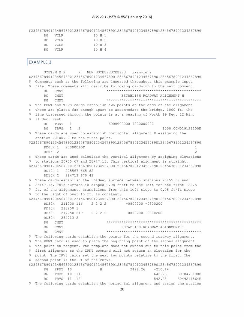
BGS v9.1 USER GUIDE (January 2016)
20
$2345678901234567890123456789012345678901234567890123456789012345678901234567890
RG VCLR 10 H 1
RG VCLR 10 H 2
RG VCLR 10 H 3
RG VCLR 10 H 4
EXAMPLE 2
SYSTEM X X X NEW NOYESYESYESYES Example 2
$2345678901234567890123456789012345678901234567890123456789012345678901234567890
$ Comments such as the following are inserted throughout this example input
$ file. These comments will describe following cards up to the next comment.
RG CMNT ********************************************
RG CMNT ESTABLISH ROADWAY ALIGNMENT H
RG CMNT ********************************************
$ The PONT and TRVS cards establish two points at the ends of the alignment
$ These are placed far enough apart to accommodate the bridge, 1000 ft. The
$ line traversed through the points is at a bearing of North 19 Deg. 12 Min.
$ 11 Sec. East.
RG PONT 1 6000000000 4000000000
RG TRVS 1 2 1000.00N019121100E
$ These cards are used to establish horizontal alignment H assigning the
station 20+00.00 to the first point.
$2345678901234567890123456789012345678901234567890123456789012345678901234567890
RD05H 1 200000POT 1
RD05H 2 2
$ These cards are used calculate the vertical alignment by assigning elevations
$ to stations 20+55.67 and 28+47.13. This vertical alignment is straight.
$2345678901234567890123456789012345678901234567890123456789012345678901234567890
RD10H 1 205567 665.82
RD10H 2 284713 670.43
$ These cards establish the roadway surface between stations 20+55.67 and
$ 28+47.13. This surface is sloped 0.08 ft/ft to the left for the first 122.5
$ ft. of the alignment, transitions from this left slope to 0.08 ft/ft slope
$ to the right of over 45 ft. is constant.
$2345678901234567890123456789012345678901234567890123456789012345678901234567890
RD30H 211000 11F 2 2 2 2 -0800200 -0800200
RD30H 213250 1
RD30H 217750 21F 2 2 2 2 0800200 0800200
RD30H 284713 2
RG CMNT ********************************************
RG CMNT ESTABLISH ROADWAY ALIGNMENT I
RG CMNT ********************************************
$ The following cards establish the points for the second roadway alignment.
$ The ZPNT card is used to place the beginning point of the second alignment
$ The point on tangent. The template does not extend out to this point from the
$ first alignment so the ZPNT command will not return an elevation for the
$ point. The TRVS cards set the next two points relative to the first. The
$ second point is the PI of the curve.
$2345678901234567890123456789012345678901234567890123456789012345678901234567890
RG ZPNT 10 H 2429.26 -210.44
RG TRVS 10 11 642.25 S070473100E
RG TRVS 11 12 542.25 S049211864E
$ The following cards establish the horizontal alignment and assign the station
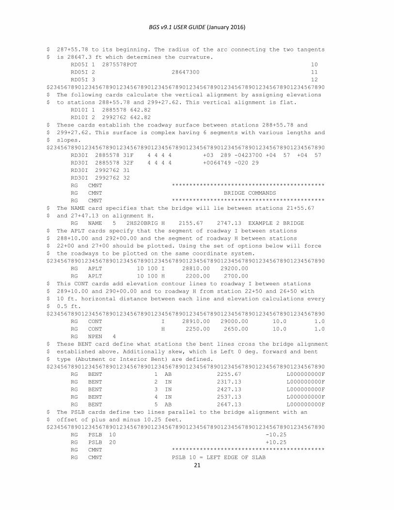
BGS v9.1 USER GUIDE (January 2016)
21
$ 287+55.78 to its beginning. The radius of the arc connecting the two tangents
$ is 28647.3 ft which determines the curvature.
RD05I 1 2875578POT 10
RD05I 2 28647300 11
RD05I 3 12
$2345678901234567890123456789012345678901234567890123456789012345678901234567890
$ The following cards calculate the vertical alignment by assigning elevations
$ to stations 288+55.78 and 299+27.62. This vertical alignment is flat.
RD10I 1 2885578 642.82
RD10I 2 2992762 642.82
$ These cards establish the roadway surface between stations 288+55.78 and
$ 299+27.62. This surface is complex having 6 segments with various lengths and
$ slopes.
$2345678901234567890123456789012345678901234567890123456789012345678901234567890
RD30I 2885578 31F 4 4 4 4 +03 289 -0423700 +04 57 +04 57
RD30I 2885578 32F 4 4 4 4 +0064749 -020 29
RD30I 2992762 31
RD30I 2992762 32
RG CMNT ********************************************
RG CMNT BRIDGE COMMANDS
RG CMNT ********************************************
$ The NAME card specifies that the bridge will lie between stations 21+55.67
$ and 27+47.13 on alignment H.
RG NAME 5 2HS20BRIG H 2155.67 2747.13 EXAMPLE 2 BRIDGE
$ The APLT cards specify that the segment of roadway I between stations
$ 288+10.00 and 292+00.00 and the segment of roadway H between stations
$ 22+00 and 27+00 should be plotted. Using the set of options below will force
$ the roadways to be plotted on the same coordinate system.
$2345678901234567890123456789012345678901234567890123456789012345678901234567890
RG APLT 10 100 I 28810.00 29200.00
RG APLT 10 100 H 2200.00 2700.00
$ This CONT cards add elevation contour lines to roadway I between stations
$ 289+10.00 and 290+00.00 and to roadway H from station 22+50 and 26+50 with
$ 10 ft. horizontal distance between each line and elevation calculations every
$ 0.5 ft.
$2345678901234567890123456789012345678901234567890123456789012345678901234567890
RG CONT I 28910.00 29000.00 10.0 1.0
RG CONT H 2250.00 2650.00 10.0 1.0
RG NPEN 4
$ These BENT card define what stations the bent lines cross the bridge alignment
$ established above. Additionally skew, which is Left 0 deg. forward and bent
$ type (Abutment or Interior Bent) are defined.
$2345678901234567890123456789012345678901234567890123456789012345678901234567890
RG BENT 1 AB 2255.67 L000000000F
RG BENT 2 IN 2317.13 L000000000F
RG BENT 3 IN 2427.13 L000000000F
RG BENT 4 IN 2537.13 L000000000F
RG BENT 5 AB 2647.13 L000000000F
$ The PSLB cards define two lines parallel to the bridge alignment with an
$ offset of plus and minus 10.25 feet.
$2345678901234567890123456789012345678901234567890123456789012345678901234567890
RG PSLB 10 -10.25
RG PSLB 20 +10.25
RG CMNT ********************************************
RG CMNT PSLB 10 = LEFT EDGE OF SLAB
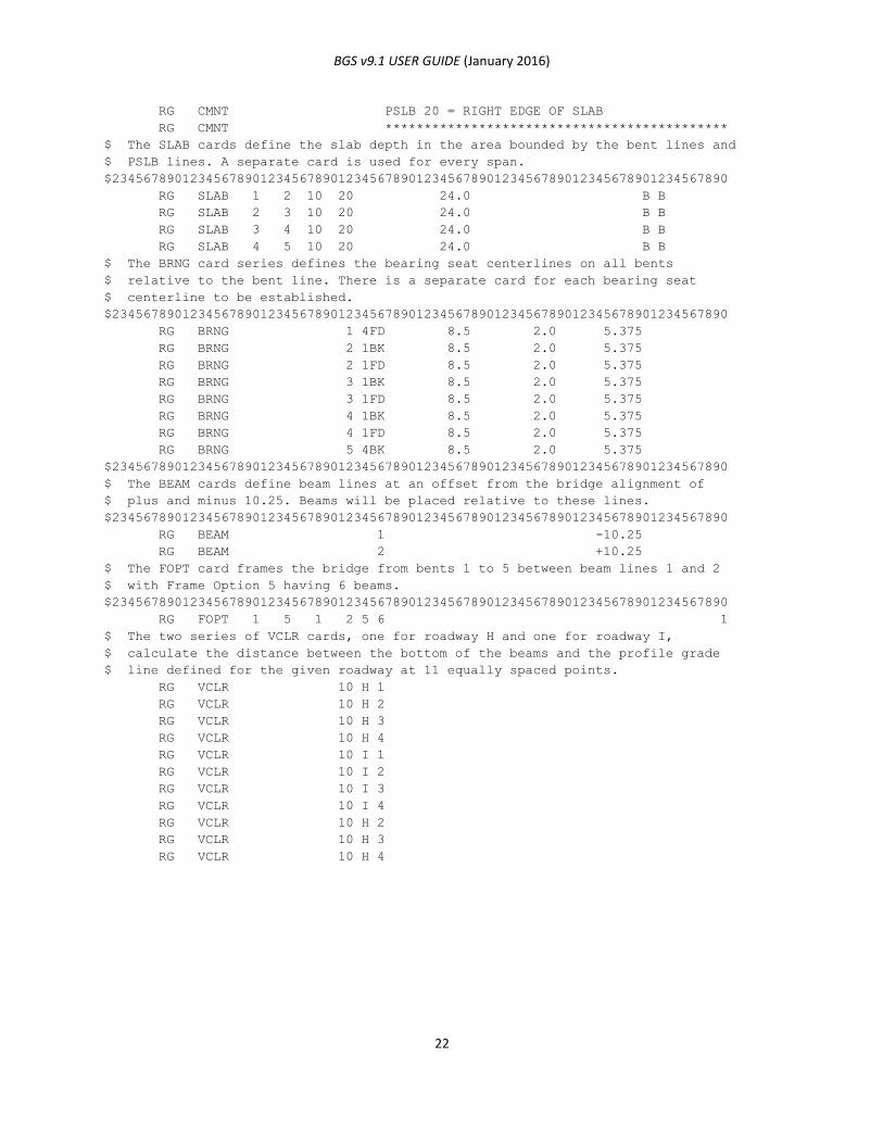
BGS v9.1 USER GUIDE (January 2016)
22
RG CMNT PSLB 20 = RIGHT EDGE OF SLAB
RG CMNT ********************************************
$ The SLAB cards define the slab depth in the area bounded by the bent lines and
$ PSLB lines. A separate card is used for every span.
$2345678901234567890123456789012345678901234567890123456789012345678901234567890
RG SLAB 1 2 10 20 24.0 B B
RG SLAB 2 3 10 20 24.0 B B
RG SLAB 3 4 10 20 24.0 B B
RG SLAB 4 5 10 20 24.0 B B
$ The BRNG card series defines the bearing seat centerlines on all bents
$ relative to the bent line. There is a separate card for each bearing seat
$ centerline to be established.
$2345678901234567890123456789012345678901234567890123456789012345678901234567890
RG BRNG 1 4FD 8.5 2.0 5.375
RG BRNG 2 1BK 8.5 2.0 5.375
RG BRNG 2 1FD 8.5 2.0 5.375
RG BRNG 3 1BK 8.5 2.0 5.375
RG BRNG 3 1FD 8.5 2.0 5.375
RG BRNG 4 1BK 8.5 2.0 5.375
RG BRNG 4 1FD 8.5 2.0 5.375
RG BRNG 5 4BK 8.5 2.0 5.375
$2345678901234567890123456789012345678901234567890123456789012345678901234567890
$ The BEAM cards define beam lines at an offset from the bridge alignment of
$ plus and minus 10.25. Beams will be placed relative to these lines.
$2345678901234567890123456789012345678901234567890123456789012345678901234567890
RG BEAM 1 -10.25
RG BEAM 2 +10.25
$ The FOPT card frames the bridge from bents 1 to 5 between beam lines 1 and 2
$ with Frame Option 5 having 6 beams.
$2345678901234567890123456789012345678901234567890123456789012345678901234567890
RG FOPT 1 5 1 2 5 6 1
$ The two series of VCLR cards, one for roadway H and one for roadway I,
$ calculate the distance between the bottom of the beams and the profile grade
$ line defined for the given roadway at 11 equally spaced points.
RG VCLR 10 H 1
RG VCLR 10 H 2
RG VCLR 10 H 3
RG VCLR 10 H 4
RG VCLR 10 I 1
RG VCLR 10 I 2
RG VCLR 10 I 3
RG VCLR 10 I 4
RG VCLR 10 H 2
RG VCLR 10 H 3
RG VCLR 10 H 4
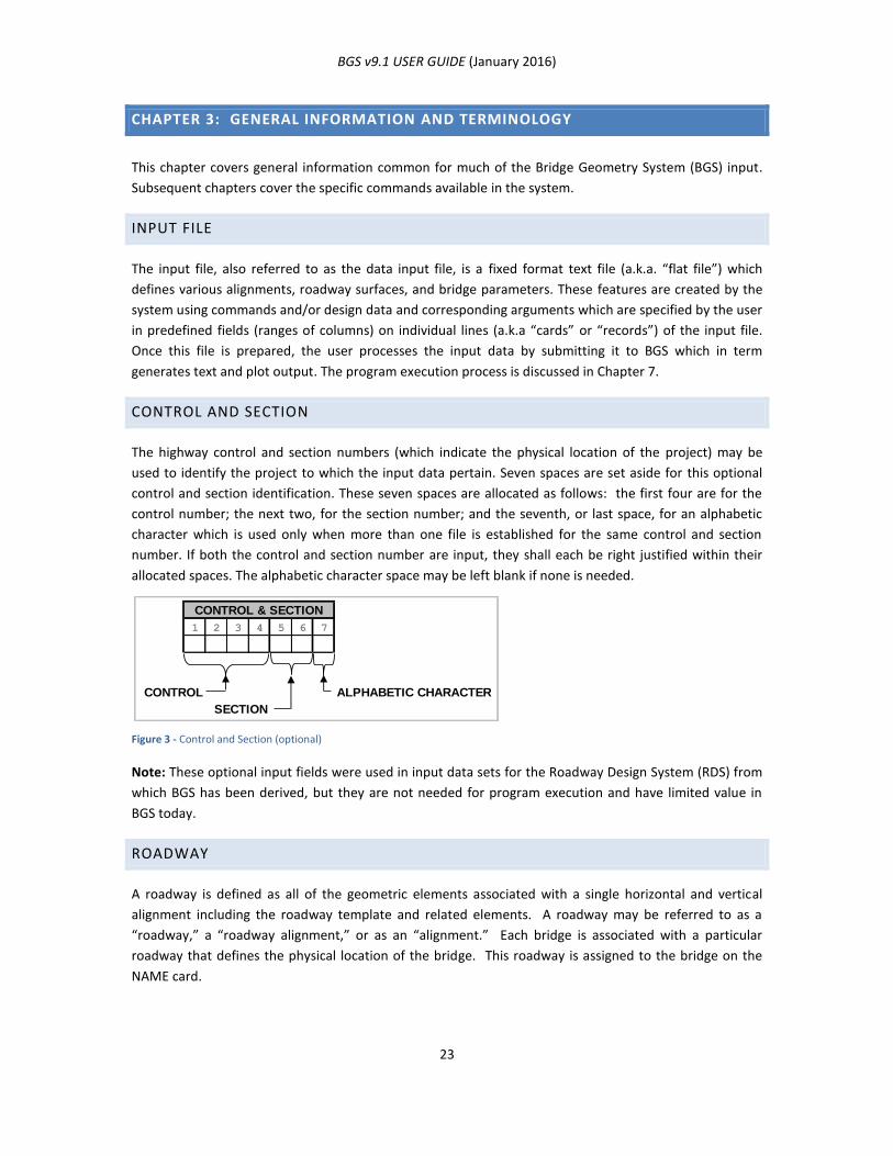
BGS v9.1 USER GUIDE (January 2016)
23
CHAPTER 3: GENERAL INFORMATION AND TERMINOLOGY
This chapter covers general information common for much of the Bridge Geometry System (BGS) input.
Subsequent chapters cover the specific commands available in the system.
INPUT FILE
The input file, also referred to as the data input file, is a fixed format text file (a.k.a. “flat file”) which
defines various alignments, roadway surfaces, and bridge parameters. These features are created by the
system using commands and/or design data and corresponding arguments which are specified by the user
in predefined fields (ranges of columns) on individual lines (a.k.a “cards” or “records”) of the input file.
Once this file is prepared, the user processes the input data by submitting it to BGS which in term
generates text and plot output. The program execution process is discussed in Chapter 7.
CONTROL AND SECTION
The highway control and section numbers (which indicate the physical location of the project) may be
used to identify the project to which the input data pertain. Seven spaces are set aside for this optional
control and section identification. These seven spaces are allocated as follows: the first four are for the
control number; the next two, for the section number; and the seventh, or last space, for an alphabetic
character which is used only when more than one file is established for the same control and section
number. If both the control and section number are input, they shall each be right justified within their
allocated spaces. The alphabetic character space may be left blank if none is needed.
Figure 3 - Control and Section (optional)
Note: These optional input fields were used in input data sets for the Roadway Design System (RDS) from
which BGS has been derived, but they are not needed for program execution and have limited value in
BGS today.
ROADWAY
A roadway is defined as all of the geometric elements associated with a single horizontal and vertical
alignment including the roadway template and related elements. A roadway may be referred to as a
“roadway,” a “roadway alignment,” or as an “alignment.” Each bridge is associated with a particular
roadway that defines the physical location of the bridge. This roadway is assigned to the bridge on the
NAME card.
1 2 3 4 5 6 7
CONTROL ALPHABETIC CHARACTER
SECTION
CONTROL & SECTION
BGS v9.1 USER GUIDE (January 2016)
24
ROADWAY DESIGNATION
Each roadway alignment must be given an alphabetic letter designation from A through Z. This
designation is used to refer to the alignment on all data inputs. See Chapter 5: Roadway Design Data for
more information about alignments.
ROADWAY TEMPLATES
The roadway template defines the cross-section of a roadway from ridge point to ridge point (ridge points
are the points on the roadway cross-section at which, in general, the slope of the roadway changes). The
user supplies template criteria for the roadway. These criteria may be modified by widening specifications
and/or superelevation specifications which the user also supplies. The horizontal positioning of a
roadway template is determined by horizontal alignment data supplied by the user. The vertical position
of the template is determined by vertical alignment data also supplied by the user.
DESIGN DATA
All user input which describes the bridge reference roadway and any related roadways are classified as
design data. Design data include the definitions of the roadways, their horizontal and vertical alignments,
and their templates, widths, and superelevations.
STATIONS
Every location on a horizontal alignment is identified by a station number. Each location on the alignment
must have a unique station number. The difference between the station numbers of two locations on the
alignment is a measure of the distance between the locations.
STATION EQUATIONS
Equations are necessary when horizontal alignments from two or more sources are combined to make
one horizontal alignment. If the first alignment consists of stations from 1+00.00 to 21+76.20 and the
second consists of stations from 25+00.00 to 70+00.00, the combined alignment would have an equation
of 21+76.20 BACK = 25+00.00 FORWARD. This statement is known as a gap equation. On the combined
alignment, the stations which originated from the second alignment would keep their original form, and
each station number would be unique.
On the other hand, if the second alignment consists of stations from 19+00.00 to 70+00.00, the combined
alignment would have an equation of 21+76.20 BACK = 19+00.00 FORWARD. Because the stations from
19+00.00 FORWARD to 21+76.20 BACK are not unique, the system adds 10,000 to all stations which are
derived from the second alignment. This would change the equation to 21+76.20 BACK = 10019+00.00
FORWARD, and all stations on the combined alignment would be unique. This adjustment of station
numbers has the effect of making a gap equation out of an overlapping equation.
The distance between two locations on the alignment is the difference between their station numbers,
minus the sum of all equation gaps, if any, between them.

BGS v9.1 USER GUIDE (January 2016)
25
A uniform scheme for inputting stations is used in all phases of the Bridge Geometry System. Stations are
entered to the nearest one-hundredth of a foot. The leftmost space of the station number is reserved for
an overlapping equation number. This number becomes a part of the station number.
The use of one space for handling overlapping equations allows a maximum of nine overlapping equations
in a station line. The number of gap equations is not limited. However, limitations are placed on the total
number of equations allowed per alignment. These limitations are discussed in Chapter 5: Roadway
Design Data.
ALPHABETIC ENTRIES
Any letter of the alphabet (case does not matter) may be used when alphabetic entries are made.
ALPHANUMERIC ENTRIES
Alphanumeric entries may be any letter of the alphabet, upper and lower case, the numbers 0 through 9,
the symbols / + - . ( ) $ * , = # ‘ % @, or blank.
COMMENTS
When comments are allowed, they are to be alphanumeric entries in specified columns.
FIELD
A field is a fixed range of columns set aside on a card (line) of input data for a specific data entry. The
various fields on data card images in this guide have titles indicating each field name (usage). The data
entered in these fields constitute the function/commands invoked and the arguments required for BGS to
perform these function/commands.
JUSTIFYING
Some data entries must be placed in specific positions within a field to be recognized correctly by the
program. When “left justified” is specified, the data must be entered starting with the leftmost column or
space of the field. When “right justified” is specified, the rightmost character of the input data must fall in
the rightmost column or space of the field.
NUMERIC ENTRIES
Numeric entries consist of real (floating point) or integer numbers made up of digits 0 through 9. In the
case of real data, numeric entries may include either an explicit or implicit decimal.
REAL (FLOATING POINT) NUMBERS
Real floating point numbers are numbers that contain floating decimal points. For example, the numbers
5.5, 0.001, and -2,345.6789 are floating point numbers. Such a real number can be entered without the
decimal place when the input field contains an implied decimal. An integer can also be a real number but

BGS v9.1 USER GUIDE (January 2016)
26
a floating point number with a non-zero digit to the right of the decimal cannot be represented as an
integer. The number zero is both an integer and a real number.
INTEGER NUMBERS
An integer is a whole number (not a fraction) that can be positive, negative, or zero. Therefore, the
numbers 10, 0, -25, and 5,148 are all integers. Unlike floating point numbers, integers cannot have
decimal places.
EXPLICIT DECIMAL POINT
Explicit decimal points, when used (input by the user), occupy one column of a field. Thus, they reduce by
one the maximum number of digits that could otherwise be entered in the field. If no decimal is input for
real numeric input, one is implied in the location shown on the data input card for the specific command.
Many fields have implied decimals that provide for four digits to the right of the decimal.
IMPLICIT DECIMAL POINT
An implicit (i.e. implied) decimal point will be shown on data input cards as a preprinted decimal between
columns. Digits in columns to the left of the implied decimal will be read as the whole number portion of
the numeric input while those to the right of the implied decimal will be read as the decimal or non-whole
(i.e. fractional) number portion of the real number. Data must be entered in accordance with an implied
decimal point unless the instructions indicate that the user may override it with an explicit decimal point.
Unless explicit decimal points are allowed, implicit decimal point locations must be strictly followed due
to the way BGS reads certain numeric input fields. BGS reads some numeric input fields as integer
numbers and then converts them to real numbers based on how many digits are to the right of the
implied decimal point.
PROCESS
A process refers to the instructions and subsequent computations involved in arriving at the resolution of
to specific operations.
RUN
A run is one submission of a data set to the system as well as the processing and output that result from
that submission.
DIAGNOSTIC MESSAGES
When the program identifies a problem, a diagnostic message will be printed along with the station
number where the situation occurred or the station number nearest the location where the situation
occurred. The messages alert the user to any problems encountered by the program. These messages
are of varying degrees of severity. Some may simply serve to flag a condition that does not invalidate the
computations. Others may indicate that an error was found and the system attempted to fix it in order for
computations to continue and the user must validate that the fix resulted, or better yet the user should

BGS v9.1 USER GUIDE (January 2016)
27
modify the input to avoid the error altogether. Lastly, some error messages indicate that a fatal error that
prevents computations from being made has occurred.
The messages are printed before the first formal system output, in the LS1 file.

BGS v9.1 USER GUIDE (January 2016)
28
CHAPTER 4: SYSTEM CARD
INTRODUCTION
Every BGS input data file must contain one and only one SYSTEM card. This card provides control
information for the current job/run. The SYSTEM card must be the very first record/card/line in the file.
It is identified to BGS by its name “SYSTEM” in columns 8 thru 13.
SYSTEM CARD INPUT
The SYSTEM card is divided into a number of fixed length fields. The record format shown in the card
image below shows the length and position of each field within the record.
Card 1 - SYSTEM Card
PROJECT ID FIELD
Figure 4 - PROJECT ID Field
Any entry made in the PROJECT ID field will be displayed in the page headings of all output report files. It
will also appear in the legend of the output plot file. The field has no role in BGS other than the display of
the PROJECT ID, so it may be left blank. It can be used for the identification of reports and projects, and
has traditionally consisted of control and section numbers such as “0177-11”.
1 2 3 4 5 6 7 8 9 10 11 12 13
S Y S T E M
CO
NT
RO
L
CO
MM
AN
D
TE
RR
AIN
DE
SIG
N D
AT
A
EA
RT
HW
OR
K
VO
LU
ME
S
HA
UL
P
LO
T
XS
EC
P
LO
T
PR
OF
ILE
P
LO
T
PE
RS
PE
CT
IVE
P
LO
T
BR
IDG
E
14 15 16 17 18 19 20 21 22 23 24 25 26 27 28 29 30 31 32 33 34 35 36 37 38 39 40 41 42 43 44 45
46 47 48 49 50 51 52 53 54 55 56 57 58 59 60 61 62 63 64 65 66 67 68 69 70 71 72 73 74 75 76 77 78 79 80
PROCESSES TO BE EXECUTED
COUNTY AND HIGHWAY
(optional)
DATE
(optional)
UN
ITS
( B
lan
k, M
, o
r E
)
JOB
TYPE
(OLD
OR
NEW)
KEEP
(YES
OR
NO)
INITIALIZE
GEOMETRY
FILES
(YES
OR
NO)
INITIALIZE
DESIGN
DATA
FILES
(YES
OR
NO)
INITIALIZE
BRIDGE
FILES
(YES
OR
NO)
INPUT
DATA
(YES
OR
NO)
PROJECT ID
(optional)
1 2 3 4 5 6 7
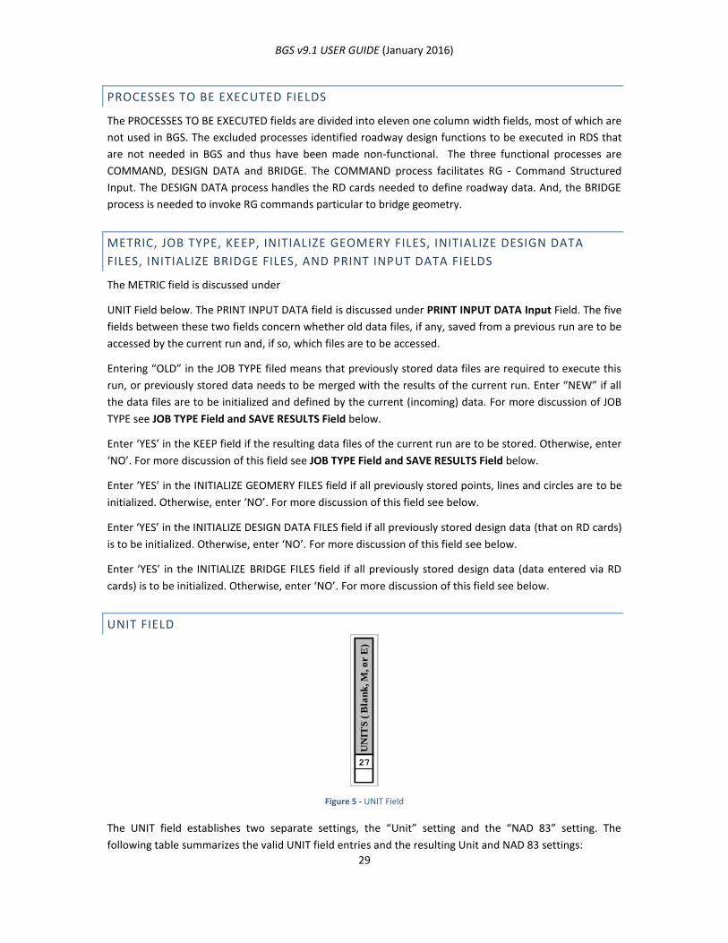
BGS v9.1 USER GUIDE (January 2016)
29
PROCESSES TO BE EXECUTED FIELDS
The PROCESSES TO BE EXECUTED fields are divided into eleven one column width fields, most of which are
not used in BGS. The excluded processes identified roadway design functions to be executed in RDS that
are not needed in BGS and thus have been made non-functional. The three functional processes are
COMMAND, DESIGN DATA and BRIDGE. The COMMAND process facilitates RG - Command Structured
Input. The DESIGN DATA process handles the RD cards needed to define roadway data. And, the BRIDGE
process is needed to invoke RG commands particular to bridge geometry.
METRIC, JOB TYPE, KEEP, INITIALIZE GEOMERY FILES, INITIALIZE DESIGN DATA
FILES, INITIALIZE BRIDGE FILES, AND PRINT INPUT DATA FIELDS
The METRIC field is discussed under
UNIT Field below. The PRINT INPUT DATA field is discussed under PRINT INPUT DATA Input Field. The five
fields between these two fields concern whether old data files, if any, saved from a previous run are to be
accessed by the current run and, if so, which files are to be accessed.
Entering “OLD” in the JOB TYPE filed means that previously stored data files are required to execute this
run, or previously stored data needs to be merged with the results of the current run. Enter “NEW” if all
the data files are to be initialized and defined by the current (incoming) data. For more discussion of JOB
TYPE see JOB TYPE Field and SAVE RESULTS Field below.
Enter ‘YES’ in the KEEP field if the resulting data files of the current run are to be stored. Otherwise, enter
‘NO’. For more discussion of this field see JOB TYPE Field and SAVE RESULTS Field below.
Enter ‘YES’ in the INITIALIZE GEOMERY FILES field if all previously stored points, lines and circles are to be
initialized. Otherwise, enter ‘NO’. For more discussion of this field see below.
Enter ‘YES’ in the INITIALIZE DESIGN DATA FILES field if all previously stored design data (that on RD cards)
is to be initialized. Otherwise, enter ‘NO’. For more discussion of this field see below.
Enter ‘YES’ in the INITIALIZE BRIDGE FILES field if all previously stored design data (data entered via RD
cards) is to be initialized. Otherwise, enter ‘NO’. For more discussion of this field see below.
UNIT FIELD
Figure 5 - UNIT Field
The UNIT field establishes two separate settings, the “Unit” setting and the “NAD 83” setting. The
following table summarizes the valid UNIT field entries and the resulting Unit and NAD 83 settings:
27
UN
ITS
( B
lan
k, M
, o
r E
)
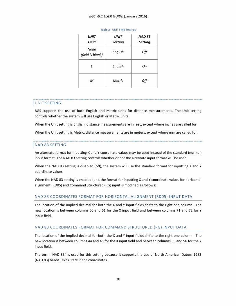
BGS v9.1 USER GUIDE (January 2016)
30
Table 2 - UNIT Field Settings
UNIT
Field
UNIT
Setting
NAD 83
Setting
None
(field is blank) English Off
E English On
M Metric Off
UNIT SETTING
BGS supports the use of both English and Metric units for distance measurements. The Unit setting
controls whether the system will use English or Metric units.
When the Unit setting is English, distance measurements are in feet, except where inches are called for.
When the Unit setting is Metric, distance measurements are in meters, except where mm are called for.
NAD 83 SETTING
An alternate format for inputting X and Y coordinate values may be used instead of the standard (normal)
input format. The NAD 83 setting controls whether or not the alternate input format will be used.
When the NAD 83 setting is disabled (off), the system will use the standard format for inputting X and Y
coordinate values.
When the NAD 83 setting is enabled (on), the format for inputting X and Y coordinate values for horizontal
alignment (RD05) and Command Structured (RG) input is modified as follows:
NAD 83 COORDINATES FORMAT FOR HORIZONTAL ALIGNMENT (RD05) INPUT DATA
The location of the implied decimal for both the X and Y input fields shifts to the right one column. The
new location is between columns 60 and 61 for the X input field and between columns 71 and 72 for Y
input field.
NAD 83 COORDINATES FORMAT FOR COMMAND STRUCTURED (RG) INPUT DATA
The location of the implied decimal for both the X and Y input fields shifts to the right one column. The
new location is between columns 44 and 45 for the X input field and between columns 55 and 56 for the Y
input field.
The term “NAD 83” is used for this setting because it supports the use of North American Datum 1983
(NAD 83) based Texas State Plane coordinates.
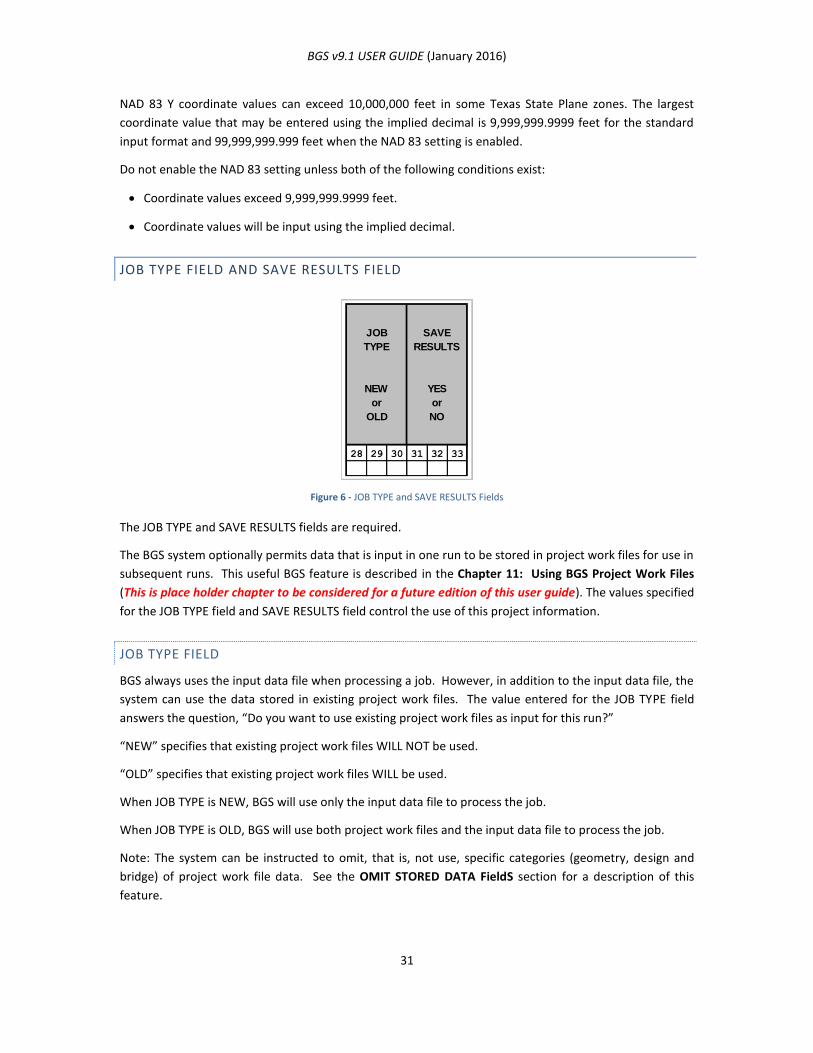
BGS v9.1 USER GUIDE (January 2016)
31
NAD 83 Y coordinate values can exceed 10,000,000 feet in some Texas State Plane zones. The largest
coordinate value that may be entered using the implied decimal is 9,999,999.9999 feet for the standard
input format and 99,999,999.999 feet when the NAD 83 setting is enabled.
Do not enable the NAD 83 setting unless both of the following conditions exist:
Coordinate values exceed 9,999,999.9999 feet.
Coordinate values will be input using the implied decimal.
JOB TYPE FIELD AND SAVE RESULTS FIELD
Figure 6 - JOB TYPE and SAVE RESULTS Fields
The JOB TYPE and SAVE RESULTS fields are required.
The BGS system optionally permits data that is input in one run to be stored in project work files for use in
subsequent runs. This useful BGS feature is described in the Chapter 11: Using BGS Project Work Files
(This is place holder chapter to be considered for a future edition of this user guide). The values specified
for the JOB TYPE field and SAVE RESULTS field control the use of this project information.
JOB TYPE FIELD
BGS always uses the input data file when processing a job. However, in addition to the input data file, the
system can use the data stored in existing project work files. The value entered for the JOB TYPE field
answers the question, “Do you want to use existing project work files as input for this run?”
“NEW” specifies that existing project work files WILL NOT be used.
“OLD” specifies that existing project work files WILL be used.
When JOB TYPE is NEW, BGS will use only the input data file to process the job.
When JOB TYPE is OLD, BGS will use both project work files and the input data file to process the job.
Note: The system can be instructed to omit, that is, not use, specific categories (geometry, design and
bridge) of project work file data. See the OMIT STORED DATA FieldS section for a description of this
feature.
JOB
TYPE
NEW
or
OLD
SAVE
RESULTS
YES
or
NO
28 29 30 31 32 33
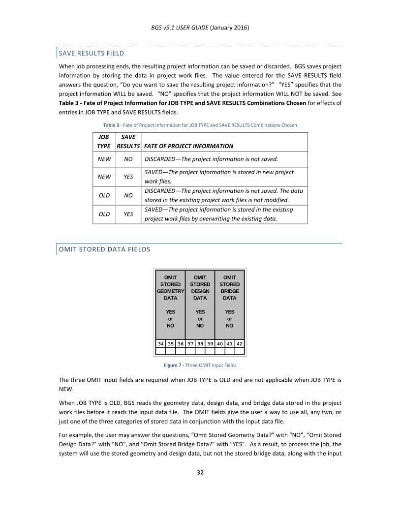
BGS v9.1 USER GUIDE (January 2016)
32
SAVE RESULTS FIELD
When job processing ends, the resulting project information can be saved or discarded. BGS saves project
information by storing the data in project work files. The value entered for the SAVE RESULTS field
answers the question, “Do you want to save the resulting project information?” “YES” specifies that the
project information WILL be saved. “NO” specifies that the project information WILL NOT be saved. See
Table 3 - Fate of Project Information for JOB TYPE and SAVE RESULTS Combinations Chosen for effects of
entries in JOB TYPE and SAVE RESULTS fields.
Table 3 - Fate of Project Information for JOB TYPE and SAVE RESULTS Combinations Chosen
JOB
TYPE
SAVE
RESULTS FATE OF PROJECT INFORMATION
NEW NO DISCARDED—The project information is not saved.
NEW YES SAVED—The project information is stored in new project
work files.
OLD NO DISCARDED—The project information is not saved. The data
stored in the existing project work files is not modified.
OLD YES SAVED—The project information is stored in the existing
project work files by overwriting the existing data.
OMIT STORED DATA FIELDS
Figure 7 - Three OMIT Input Fields
The three OMIT input fields are required when JOB TYPE is OLD and are not applicable when JOB TYPE is
NEW.
When JOB TYPE is OLD, BGS reads the geometry data, design data, and bridge data stored in the project
work files before it reads the input data file. The OMIT fields give the user a way to use all, any two, or
just one of the three categories of stored data in conjunction with the input data file.
For example, the user may answer the questions, “Omit Stored Geometry Data?” with “NO”, “Omit Stored
Design Data?” with “NO”, and “Omit Stored Bridge Data?” with “YES”. As a result, to process the job, the
system will use the stored geometry and design data, but not the stored bridge data, along with the input
OMIT
STORED
GEOMETRY
DATA
YES
or
NO
OMIT
STORED
DESIGN
DATA
YES
or
NO
OMIT
STORED
BRIDGE
DATA
YES
or
NO
34 35 36 37 38 39 40 41 42
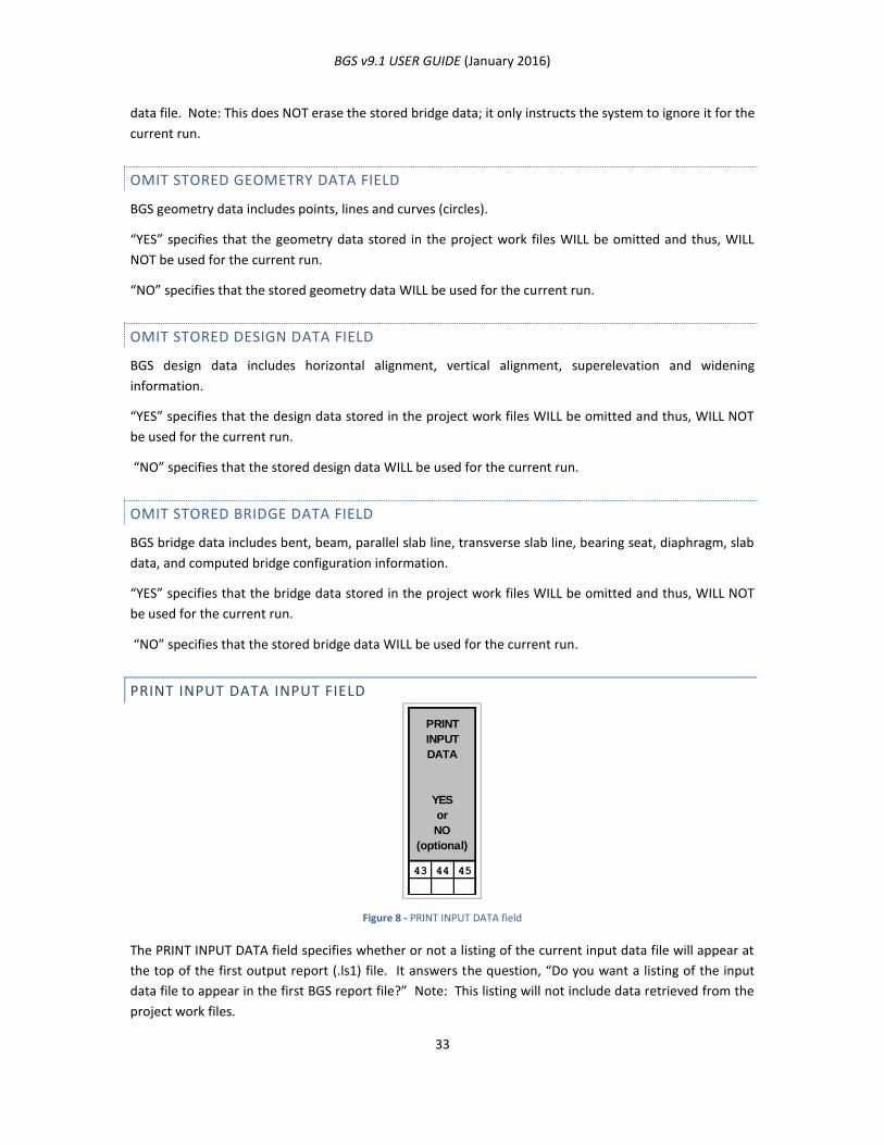
BGS v9.1 USER GUIDE (January 2016)
33
data file. Note: This does NOT erase the stored bridge data; it only instructs the system to ignore it for the
current run.
OMIT STORED GEOMETRY DATA FIELD
BGS geometry data includes points, lines and curves (circles).
“YES” specifies that the geometry data stored in the project work files WILL be omitted and thus, WILL
NOT be used for the current run.
“NO” specifies that the stored geometry data WILL be used for the current run.
OMIT STORED DESIGN DATA FIELD
BGS design data includes horizontal alignment, vertical alignment, superelevation and widening
information.
“YES” specifies that the design data stored in the project work files WILL be omitted and thus, WILL NOT
be used for the current run.
“NO” specifies that the stored design data WILL be used for the current run.
OMIT STORED BRIDGE DATA FIELD
BGS bridge data includes bent, beam, parallel slab line, transverse slab line, bearing seat, diaphragm, slab
data, and computed bridge configuration information.
“YES” specifies that the bridge data stored in the project work files WILL be omitted and thus, WILL NOT
be used for the current run.
“NO” specifies that the stored bridge data WILL be used for the current run.
PRINT INPUT DATA INPUT FIELD
Figure 8 - PRINT INPUT DATA field
The PRINT INPUT DATA field specifies whether or not a listing of the current input data file will appear at
the top of the first output report (.ls1) file. It answers the question, “Do you want a listing of the input
data file to appear in the first BGS report file?” Note: This listing will not include data retrieved from the
project work files.
INPUT
DATA
YES
or
NO
(optional)
43 44 45

BGS v9.1 USER GUIDE (January 2016)
34
“YES” generates a listing of the input data file at the top of the first report file.
“NO” does NOT generate a listing of the input data file.
Leaving the field blank is valid, and is the same as specifying “YES”.
COMMENT INPUT FIELD
Figure 9 - COMMENT Input Field
Any entry in the COMMENT field will be displayed in the page headings of all output report files. It will
also appear in the legend of the output plot file. The field has no role in BGS other than display, so it may
be left blank. Like the PROJECT ID field, the COMMENT field can be used for the identification of reports
or projects. For example, the names of the county and highway associated with the project could be
specified, such as “Harris, US-59”.
COMMENT
(optional)
49 50 51 52 53 54 55 56 57 58 59 60 61 62 63 64 65 66 67 68 69 70 71 72 73 74 75 76 77 78 79 80
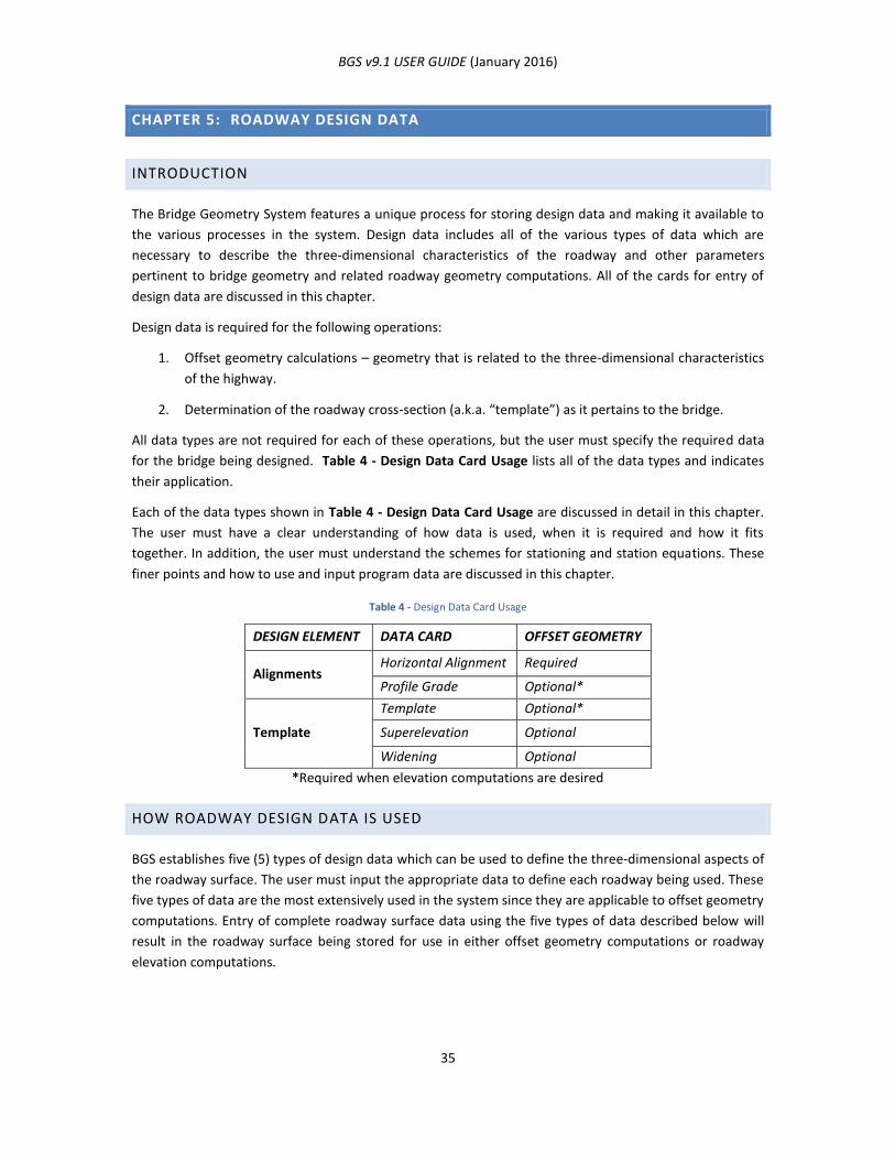
BGS v9.1 USER GUIDE (January 2016)
35
CHAPTER 5: ROADWAY DESIGN DATA
INTRODUCTION
The Bridge Geometry System features a unique process for storing design data and making it available to
the various processes in the system. Design data includes all of the various types of data which are
necessary to describe the three-dimensional characteristics of the roadway and other parameters
pertinent to bridge geometry and related roadway geometry computations. All of the cards for entry of
design data are discussed in this chapter.
Design data is required for the following operations:
1. Offset geometry calculations – geometry that is related to the three-dimensional characteristics
of the highway.
2. Determination of the roadway cross-section (a.k.a. “template”) as it pertains to the bridge.
All data types are not required for each of these operations, but the user must specify the required data
for the bridge being designed. Table 4 - Design Data Card Usage lists all of the data types and indicates
their application.
Each of the data types shown in Table 4 - Design Data Card Usage are discussed in detail in this chapter.
The user must have a clear understanding of how data is used, when it is required and how it fits
together. In addition, the user must understand the schemes for stationing and station equations. These
finer points and how to use and input program data are discussed in this chapter.
Table 4 - Design Data Card Usage
DESIGN ELEMENT DATA CARD OFFSET GEOMETRY
Alignments Horizontal Alignment Required
Profile Grade Optional*
Template
Template Optional*
Superelevation Optional
Widening Optional
*Required when elevation computations are desired
HOW ROADWAY DESIGN DATA IS USED
BGS establishes five (5) types of design data which can be used to define the three-dimensional aspects of
the roadway surface. The user must input the appropriate data to define each roadway being used. These
five types of data are the most extensively used in the system since they are applicable to offset geometry
computations. Entry of complete roadway surface data using the five types of data described below will
result in the roadway surface being stored for use in either offset geometry computations or roadway
elevation computations.
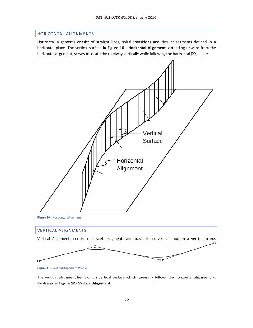
BGS v9.1 USER GUIDE (January 2016)
36
HORIZONTAL ALIGNMENTS
Horizontal alignments consist of straight lines, spiral transitions and circular segments defined in a
horizontal plane. The vertical surface in Figure 10 - Horizontal Alignment, extending upward from the
horizontal alignment, serves to locate the roadway vertically while following the horizontal (XY) plane.
Figure 10 - Horizontal Alignment
VERTICAL ALIGNMENTS
Vertical Alignments consist of straight segments and parabolic curves laid out in a vertical plane.
Figure 11 - Vertical Alignment Profile
The vertical alignment lies along a vertical surface which generally follows the horizontal alignment as
illustrated in Figure 12 - Vertical Alignment.
Vertical
Surface
Horizontal
Alignment
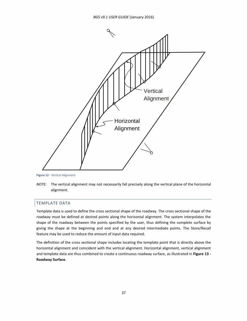
BGS v9.1 USER GUIDE (January 2016)
37
Figure 12 - Vertical Alignment
NOTE: The vertical alignment may not necessarily fall precisely along the vertical plane of the horizontal
alignment.
TEMPLATE DATA
Template data is used to define the cross sectional shape of the roadway. The cross sectional shape of the
roadway must be defined at desired points along the horizontal alignment. The system interpolates the
shape of the roadway between the points specified by the user, thus defining the complete surface by
giving the shape at the beginning and end and at any desired intermediate points. The Store/Recall
feature may be used to reduce the amount of input data required.
The definition of the cross sectional shape includes locating the template point that is directly above the
horizontal alignment and coincident with the vertical alignment. Horizontal alignment, vertical alignment
and template data are thus combined to create a continuous roadway surface, as illustrated in Figure 13 -
Roadway Surface.
Vertical
Alignment
Horizontal
Alignment
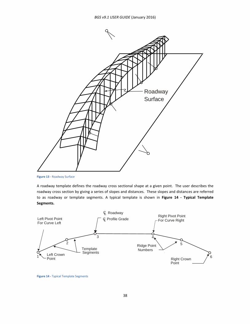
BGS v9.1 USER GUIDE (January 2016)
38
Figure 13 - Roadway Surface
A roadway template defines the roadway cross sectional shape at a given point. The user describes the
roadway cross section by giving a series of slopes and distances. These slopes and distances are referred
to as roadway or template segments. A typical template is shown in Figure 14 - Typical Template
Segments.
Figure 14 - Typical Template Segments
Roadway
Surface
Left Pivot Point For Curve Left
Left Crown Point
Template Segments
Ridge Point Numbers
Right Crown Point
Right Pivot Point For Curve Right
Roadway C L
Profile Grade C L
1
2
3 4
5
6
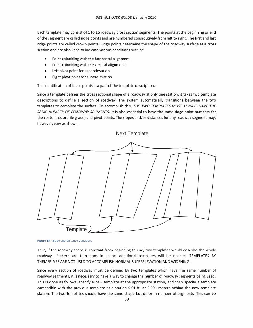
BGS v9.1 USER GUIDE (January 2016)
39
Each template may consist of 1 to 16 roadway cross section segments. The points at the beginning or end
of the segment are called ridge points and are numbered consecutively from left to right. The first and last
ridge points are called crown points. Ridge points determine the shape of the roadway surface at a cross
section and are also used to indicate various conditions such as:
Point coinciding with the horizontal alignment
Point coinciding with the vertical alignment
Left pivot point for superelevation
Right pivot point for superelevation
The identification of these points is a part of the template description.
Since a template defines the cross sectional shape of a roadway at only one station, it takes two template
descriptions to define a section of roadway. The system automatically transitions between the two
templates to complete the surface. To accomplish this, THE TWO TEMPLATES MUST ALWAYS HAVE THE
SAME NUMBER OF ROADWAY SEGMENTS. It is also essential to have the same ridge point numbers for
the centerline, profile grade, and pivot points. The slopes and/or distances for any roadway segment may,
however, vary as shown.
Figure 15 - Slope and Distance Variations
Thus, if the roadway shape is constant from beginning to end, two templates would describe the whole
roadway. If there are transitions in shape, additional templates will be needed. TEMPLATES BY
THEMSELVES ARE NOT USED TO ACCOMPLISH NORMAL SUPERELEVATION AND WIDENING.
Since every section of roadway must be defined by two templates which have the same number of
roadway segments, it is necessary to have a way to change the number of roadway segments being used.
This is done as follows: specify a new template at the appropriate station, and then specify a template
compatible with the previous template at a station 0.01 ft. or 0.001 meters behind the new template
station. The two templates should have the same shape but differ in number of segments. This can be
Next Template
Template
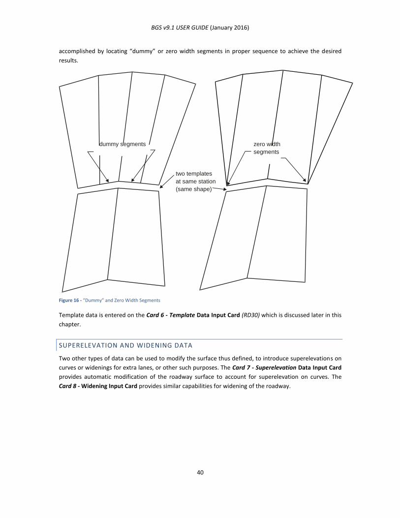
BGS v9.1 USER GUIDE (January 2016)
40
accomplished by locating “dummy” or zero width segments in proper sequence to achieve the desired
results.
Figure 16 - “Dummy” and Zero Width Segments
Template data is entered on the Card 6 - Template Data Input Card (RD30) which is discussed later in this
chapter.
SUPERELEVATION AND WIDENING DATA
Two other types of data can be used to modify the surface thus defined, to introduce superelevations on
curves or widenings for extra lanes, or other such purposes. The Card 7 - Superelevation Data Input Card
provides automatic modification of the roadway surface to account for superelevation on curves. The
Card 8 - Widening Input Card provides similar capabilities for widening of the roadway.
dummy segments zero width
segments
two templates
at same station
(same shape)
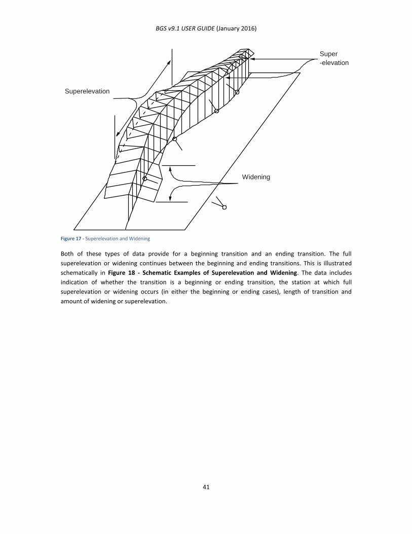
BGS v9.1 USER GUIDE (January 2016)
41
Figure 17 - Superelevation and Widening
Both of these types of data provide for a beginning transition and an ending transition. The full
superelevation or widening continues between the beginning and ending transitions. This is illustrated
schematically in Figure 18 - Schematic Examples of Superelevation and Widening. The data includes
indication of whether the transition is a beginning or ending transition, the station at which full
superelevation or widening occurs (in either the beginning or ending cases), length of transition and
amount of widening or superelevation.
Superelevation
Widening
Super
-elevation
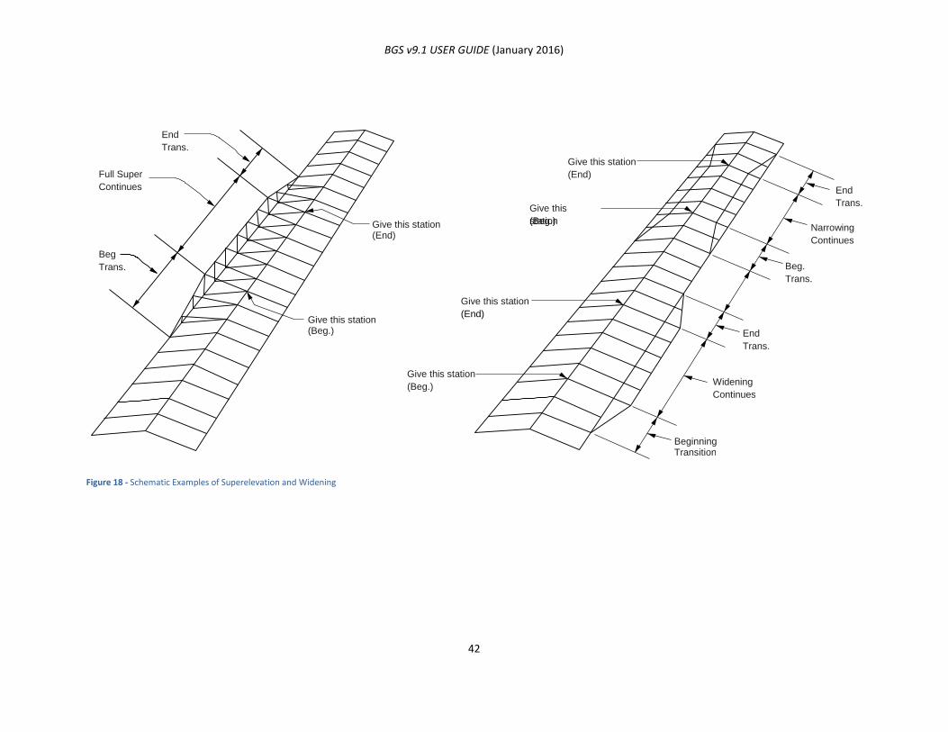
BGS v9.1 USER GUIDE (January 2016)
42
Figure 18 - Schematic Examples of Superelevation and Widening
End
Trans.
Full Super
Continues
Beg
Trans.
Give this station (End)
Give this station
(End)
End
Trans.
Narrowing
Continues
Beg.
Trans.
End
Trans.
Widening
Continues
Beginning Transition
Give this station
(Beg.)
Give this station (Beg.)
Give this
station (Beg.)
Give this station (End)

BGS v9.1 USER GUIDE (January 2016)
43
STATIONING AND EQUATION SCHEME
The Bridge Geometry System uses a stationing scheme in which all overlapping equations are eliminated by
modifying the station numbers. Gap equations do not need to be modified.
- Overlapping equations are defined as equations for which the forward station has a smaller
number than the back station, such as 10+00BK=7+50FWD.
- Gap equations are defined as equations for which the forward station has a larger number
than the back station number, such as 10+00BK=11+00FWD.
The Horizontal Alignment Calculation Process eliminates overlapping equations by adding 10,000 to the
station numbers each time an overlapping equation is passed. Nine overlapping equations are allowed in
this scheme. The leftmost digit of the adjusted station number indicates the number of overlapping
equations. The new stationing is shown on the Horizontal Alignment output and must be used in all
subsequent reference to the alignment or data entries.
The gap and overlapping equation numbering schemes are illustrated below. Examples of equations are
given in
Figure 20 - Examples of Equations.
Figure 19 - Gap and Overlapping Equation Numbering
10+
00
10+
00
7+
00
20007+
00
ACTUALSTATIONING
Overlap OverlapGap Gap
ADJUSTEDSTATIONING
15+
00
BK
15+
00
20+
00
BK
10020+
00
32+
00
BK
10032+
00
48+
00
BK
10048+
00
13+
50
FW
D10013+
50
21+
50
FW
D10021+
50
40+
00
FW
D10040+
00
0+
00F
WD
20000+
00
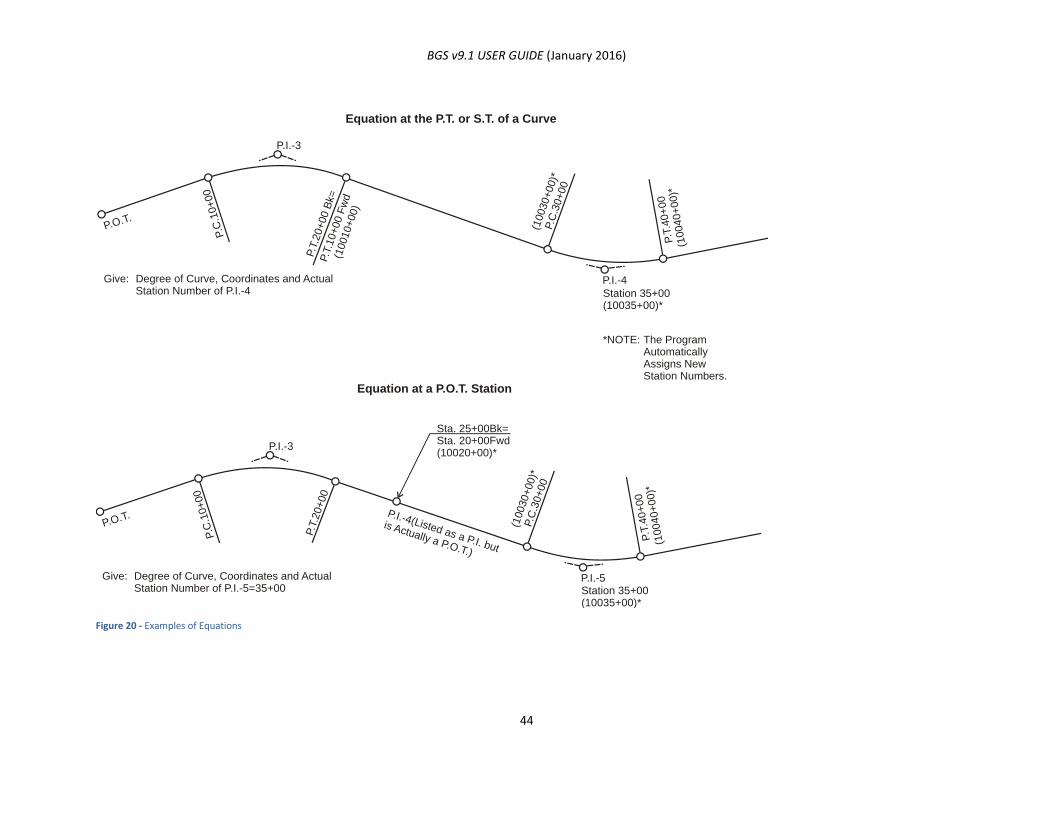
BGS v9.1 USER GUIDE (January 2016)
44
Figure 20 - Examples of Equations
P.C
.10+
00
P.C
.10+
00
P.O.T.
P.O.T.
P.T
.20+00 B
k=
P.T
.20+00
P.T
.10+00 F
wd
(10010+00)
P.T
.40+
00
(10040+
00)*
P.T
.40+
00
(10040+
00)*
(10030+00)*
P.C
.30+00
(10030+00)*
P.C
.30+00
P.I.-3
P.I.-3
P.I.-4
P.I.-5
Station 35+00(10035+00)*
Station 35+00(10035+00)*
Sta. 25+00Bk=Sta. 20+00Fwd(10020+00)*
P.I.-4(Listed as a P.I. but
is Actually a P.O.T.)
Degree of Curve, Coordinates and ActualStation Number of P.I.-4
The ProgramAutomaticallyAssigns NewStation Numbers.
Equation at the P.T. or S.T. of a Curve
Equation at a P.O.T. Station
Degree of Curve, Coordinates and ActualStation Number of P.I.-5=35+00
Give:
*NOTE:
Give:

BGS v9.1 USER GUIDE (January 2016)
45
INPUTTING ROADWAY DESIGN DATA
ROADWAY DESIGN DATA INPUT CARDS
Each data input card allows the entry of control and section. See Chapter 3: General Information and
Terminology for discussion of this data.
Each card calls for either a station or range of stations such as beginning and ending stations. In each case,
the gap and overlapping equation numbering schemes discussed in this chapter must be observed. Note
that in most cases, the station may be on any of the roadways A-Z.
Most of the cards require that the roadway be specified, which is accomplished by entering the appropriate
letter A-Z. These letters not only serve to identify the data for a roadway, but also to control the sequence
of completion of the design section by the design process. Many of the cards call for the designation left or
right. By convention, left and right directions are expressed in terms of the viewpoint of an observer
looking in the direction of increasing stations.
The data cards are designed to be as convenient to the user as possible. The cards can be used in any
order. In most cases, the cards apply to any of the applicable roadways.
HORIZONTAL ALIGNMENT DATA
INTRODUCTION
Horizontal alignments are required for offset geometry calculations as indicated in Table 4 - Design Data
Card Usage.
Figure 21 - Horizontal Alignment shows a simple alignment and indicates the limited amount of data that is
required to store the alignment. In the process of storing the alignment all of its properties are computed
and output. Figure 22 - Simple Curve Data Output and Figure 25 - Spiral Curve Data Output show the
output for simple and spiral curves, respectively.
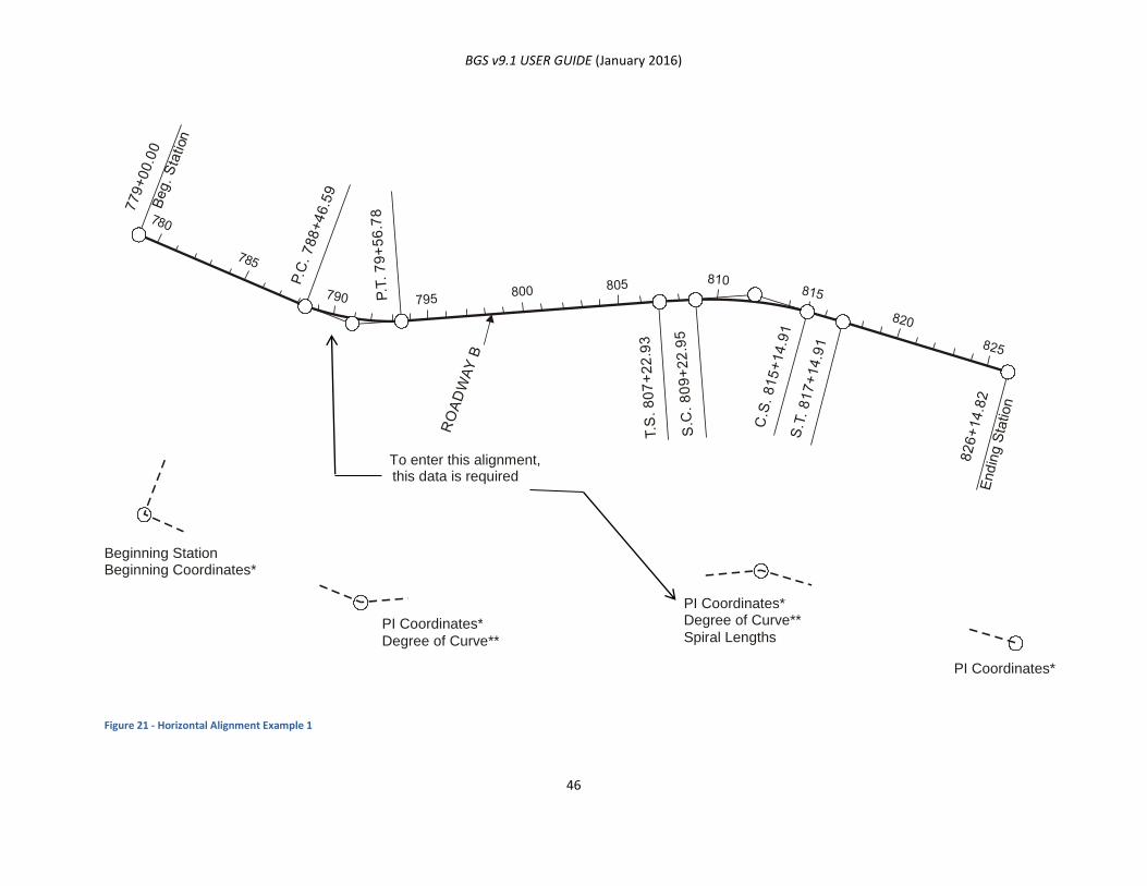
BGS v9.1 USER GUIDE (January 2016)
46
Figure 21 - Horizontal Alignment Example 1
To enter this alignment, this data is required
Beginning Station Beginning Coordinates*
PI Coordinates* Degree of Curve**
PI Coordinates* Degree of Curve** Spiral Lengths
PI Coordinates*
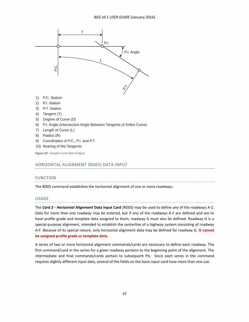
BGS v9.1 USER GUIDE (January 2016)
47
Figure 22 - Simple Curve Data Output
HORIZONTAL ALIGNMENT (RD05) DATA INPUT
FUNCTION
The RD05 command establishes the horizontal alignment of one or more roadways.
USAGE
The Card 2 - Horizontal Alignment Data Input Card (RD05) may be used to define any of the roadways A-Z.
Data for more than one roadway may be entered, but if any of the roadways A-F are defined and are to
have profile grade and template data assigned to them, roadway G must also be defined. Roadway G is a
special-purpose alignment, intended to establish the centerline of a highway system consisting of roadway
A-F. Because of its special nature, only horizontal alignment data may be defined for roadway G. It cannot
be assigned profile grade or template data.
A series of two or more horizontal alignment commands/cards are necessary to define each roadway. The
first command/card in the series for a given roadway pertains to the beginning point of the alignment. The
intermediate and final commands/cards pertain to subsequent PIs. Since each series in the command
requires slightly different input data, several of the fields on the basic input card have more than one use.
T
L
P.I.
P.C
.
P.T.
P.I. Angle
1) P.C. Station
2) P.I. Station
3) P.T. Station
4) Tangent (T)
5) Degree of Curve (D)
6) P.I. Angle (Intersection Angle Between Tangents of Entire Curve)
7) Length of Curve (L)
8) Radius (R)
9) Coordinates of P.C., P.I. and P.T.
10) Bearing of the Tangents
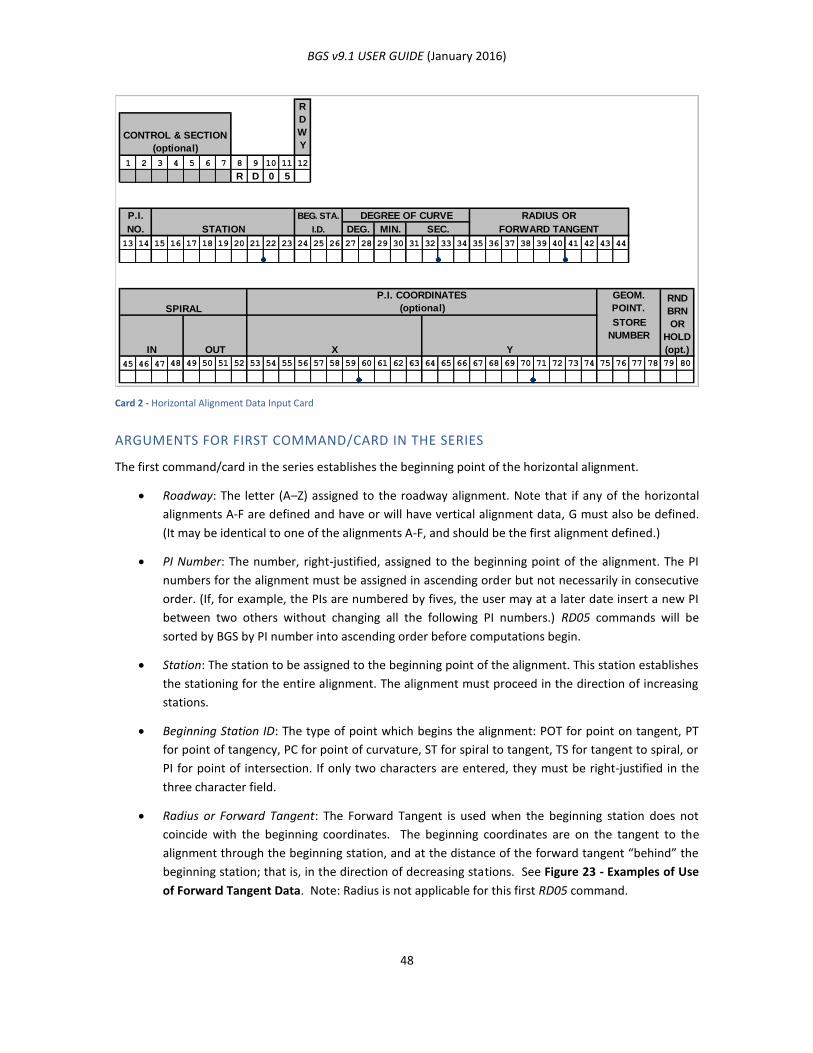
BGS v9.1 USER GUIDE (January 2016)
48
Card 2 - Horizontal Alignment Data Input Card
ARGUMENTS FOR FIRST COMMAND/CARD IN THE SERIES
The first command/card in the series establishes the beginning point of the horizontal alignment.
Roadway: The letter (A–Z) assigned to the roadway alignment. Note that if any of the horizontal
alignments A-F are defined and have or will have vertical alignment data, G must also be defined.
(It may be identical to one of the alignments A-F, and should be the first alignment defined.)
PI Number: The number, right-justified, assigned to the beginning point of the alignment. The PI
numbers for the alignment must be assigned in ascending order but not necessarily in consecutive
order. (If, for example, the PIs are numbered by fives, the user may at a later date insert a new PI
between two others without changing all the following PI numbers.) RD05 commands will be
sorted by BGS by PI number into ascending order before computations begin.
Station: The station to be assigned to the beginning point of the alignment. This station establishes
the stationing for the entire alignment. The alignment must proceed in the direction of increasing
stations.
Beginning Station ID: The type of point which begins the alignment: POT for point on tangent, PT
for point of tangency, PC for point of curvature, ST for spiral to tangent, TS for tangent to spiral, or
PI for point of intersection. If only two characters are entered, they must be right-justified in the
three character field.
Radius or Forward Tangent: The Forward Tangent is used when the beginning station does not
coincide with the beginning coordinates. The beginning coordinates are on the tangent to the
alignment through the beginning station, and at the distance of the forward tangent “behind” the
beginning station; that is, in the direction of decreasing stations. See Figure 23 - Examples of Use
of Forward Tangent Data. Note: Radius is not applicable for this first RD05 command.
CONTROL & SECTION
(optional)
1 2 3 4 5 6 7 8 9 10 11 12
R D 0 5
P.I. BEG. STA. DEGREE OF CURVE RADIUS OR
STATION I.D. DEG. MIN. SEC. FORWARD TANGENT
13 14 15 16 17 18 19 20 21 22 23 24 25 26 27 28 29 30 31 32 33 34 35 36 37 38 39 40 41 42 43 44
SPIRAL
P.I. COORDINATES
(optional)
GEOM.
POINT.
IN OUT X Y
STORE
NUMBER
45 46 47 48 49 50 51 52 53 54 55 56 57 58 59 60 61 62 63 64 65 66 67 68 69 70 71 72 73 74 75 76 77 78 79 80
NO.
R
D
W
Y
RND
BRN
OR
HOLD
(opt.)
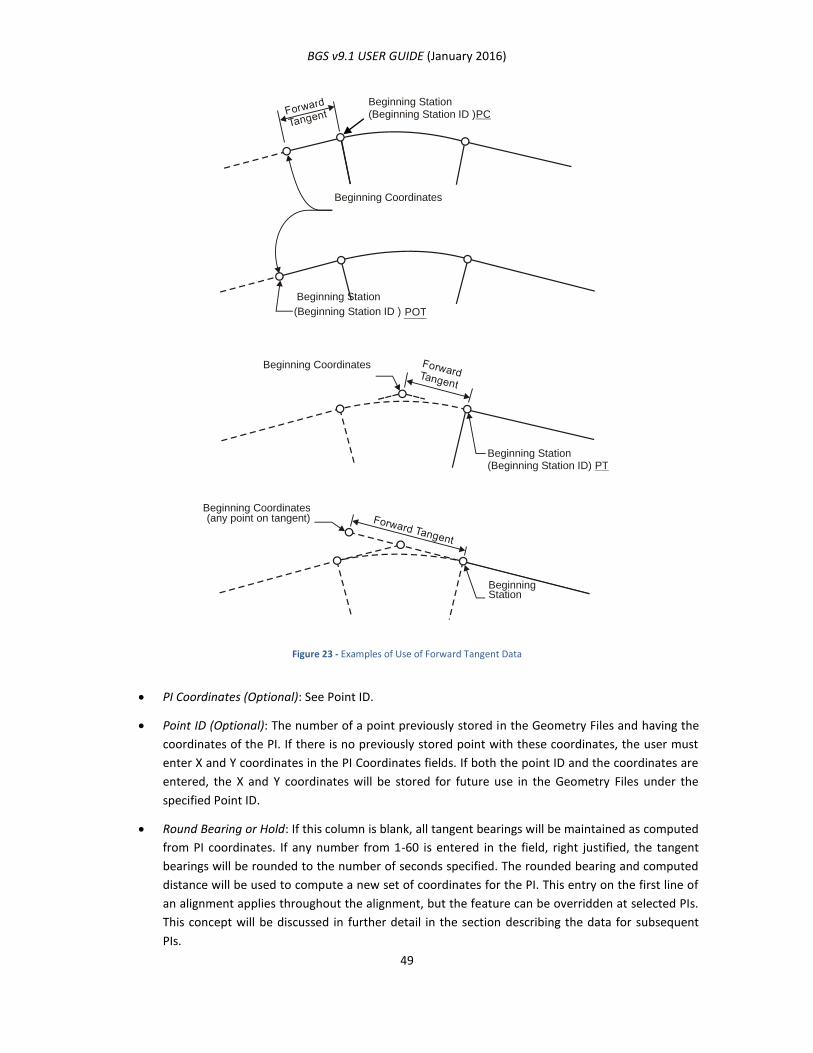
BGS v9.1 USER GUIDE (January 2016)
49
Figure 23 - Examples of Use of Forward Tangent Data
PI Coordinates (Optional): See Point ID.
Point ID (Optional): The number of a point previously stored in the Geometry Files and having the
coordinates of the PI. If there is no previously stored point with these coordinates, the user must
enter X and Y coordinates in the PI Coordinates fields. If both the point ID and the coordinates are
entered, the X and Y coordinates will be stored for future use in the Geometry Files under the
specified Point ID.
Round Bearing or Hold: If this column is blank, all tangent bearings will be maintained as computed
from PI coordinates. If any number from 1-60 is entered in the field, right justified, the tangent
bearings will be rounded to the number of seconds specified. The rounded bearing and computed
distance will be used to compute a new set of coordinates for the PI. This entry on the first line of
an alignment applies throughout the alignment, but the feature can be overridden at selected PIs.
This concept will be discussed in further detail in the section describing the data for subsequent
PIs.
Beginning Station (Beginning Station ID ) PC
Beginning Station
Beginning Station (Beginning Station ID) PT
Beginning Station (Beginning Station ID ) POT
Beginning Coordinates
Beginning Coordinates
Beginning Coordinates (any point on tangent)

BGS v9.1 USER GUIDE (January 2016)
50
ARGUMENTS FOR INTERMEDIATE COMMAND(S) IN THE SERIES
Intermediate command(s)/card(s) in the series establish a point of intersection (PI) on the horizontal
alignment.
Roadway: The letter (A–Z) assigned to the roadway alignment. Note that if any of the horizontal
alignments A-F are defined and have or will have vertical alignment data, G must also be defined.
(It may be identical to one of the alignments A-F, and should be the first alignment defined.)
PI Number: The number, right-justified, assigned to the point of intersection of two tangents. The
PI numbers for the alignment must be assigned in ascending order but not necessarily in
consecutive order. (If, for example, the PIs are numbered by fives, the user may at a later date
insert a new PI between two others without changing all the following PI numbers.) RD05
commands will be sorted by the BGS program by PI number into ascending order before
computations begin.
Station: The station to be assigned to the PI, usually left blank. BGS computes PI stations based on
the coordinate data entered and on the stations at the previous PIs. This field should be left blank
except when an equation occurs between the preceding PI and the current PI. In this case enter
the actual station for the current PI.
Degree of Curvature: The degree of curvature at a given PI is equivalent to 100 ft. divided by the
radius in feet. (The degree of curvature is not valid for metric data. For metric data, a radius must
be used to define a curve.) For English data, the user may enter the degree of curvature instead of
the radius, where the PI is not an angle point or a POT.
Radius: The radius of the circular curve at the given PI. If the Degree of Curvature is not specified or
the data is metric and the PI is not an angle point (that is, a point not “rounded off” by a circular
arc/spiral) or POT, enter the radius of the curve.
Spiral (In/Out): Length of the beginning spiral of the curve and length of the ending spiral of the
curve for In Spiral and Out Spiral, respectively. Unequal spirals may be entered for any curve. The
In Spiral will be placed between the first tangent and the beginning of the curve; the Out Spiral will
be placed between the end of the curve and the second tangent. Leave these columns blank for
simple curves. See Figure 22 - Simple Curve Data Output and Figure 25 - Spiral Curve Data Output.
PI Coordinates (Optional): See Point ID.
Point ID: The number of a point previously stored in the Geometry Files and having the coordinates
of the PI. These points are usually established using PONT and TRVS commands, but can be
established using any command with a point storage option. If there is no previously stored point
with these coordinates, the user must enter X and Y coordinates in the PI Coordinate fields. If both
the point ID and the coordinates are entered, the X and Y coordinates will be stored for future use
in the Geometry Files under the specified Point ID.
Round Bearing or Hold: Entering “H”, right justified, in this field holds the coordinates of the PI for
this command when the first command in the series specifies rounding of bearings. This feature
may be used when tying into an existing alignment. When it is used, the back bearing will not be
rounded.
BGS v9.1 USER GUIDE (January 2016)
51
ARGUMENTS FOR FINAL COMMAND IN THE SERIES
The final command/card in the series establishes the ending point of the horizontal alignment.
Roadway: The letter (A–Z) assigned to the roadway alignment. Note that if any of the horizontal
alignments A-F are defined and have or will have vertical alignment data, G must also be defined.
(It may be identical to one of the alignments A-F, and should be the first alignment defined.)
PI Number: The number, right-justified, assigned to the ending point of the alignment. The PI
numbers must be in ascending order but not necessarily in consecutive order. (If, for example, the
PIs are numbered by fives, the user may at a later date insert a new PI between two others without
changing all the PI numbers that follow the new PI.) RD05 commands will be sorted by PI number
into ascending order before computations begin.
Station: The station to be assigned to the ending point of the alignment, usually left blank. BGS
computes PI stations based on the coordinate data entered and on the stations at previous PIs.
This field should be left blank except when an equation occurs between the preceding PI and the
current PI. In this case enter the actual station for the current PI.
PI Coordinates (Optional): See Point ID.
Point ID: The number of a point previously stored in the Geometry Files and having the coordinates
of the PI. These points may be established using PONT and TRVS commands, but can be
established using any command with a point storage option. If there is no previously stored point
with these coordinates, the user must enter X and Y coordinates in the PI Coordinate fields. If both
the point ID and the coordinates are entered, the coordinates will be stored for future use in the
Geometry Files under the specified Point ID.
HORIZONTAL ALIGNMENT OUTPUT
The Horizontal Alignment Calculation Process produces:
1. Output listings of each alignment;
2. Storage of all the elements of each alignment; and
3. Geometry point storage of the specified PIs.
HORIZONTAL ALIGNMENT INPUT/OUTPUT EXAMPLES
Figure 26 - Horizontal Alignment Output for Roadway A and Figure 27 - Horizontal Alignment Output for
Roadway B are examples of horizontal alignment output listings. These listings reflect the alignment
shown in Figure 21 - Horizontal Alignment Example 1 and the input shown in Figure 24 - Horizontal
Alignment Input Example 1 and.
Note 1: Refer to Figure 26 - Horizontal Alignment Output for Roadway A.
USAGE
Figure 26 - Horizontal Alignment Output for Roadway A displays the calculated alignment data for
Roadway A and Figure 27 - Horizontal Alignment Output for Roadway B displays the calculated alignment
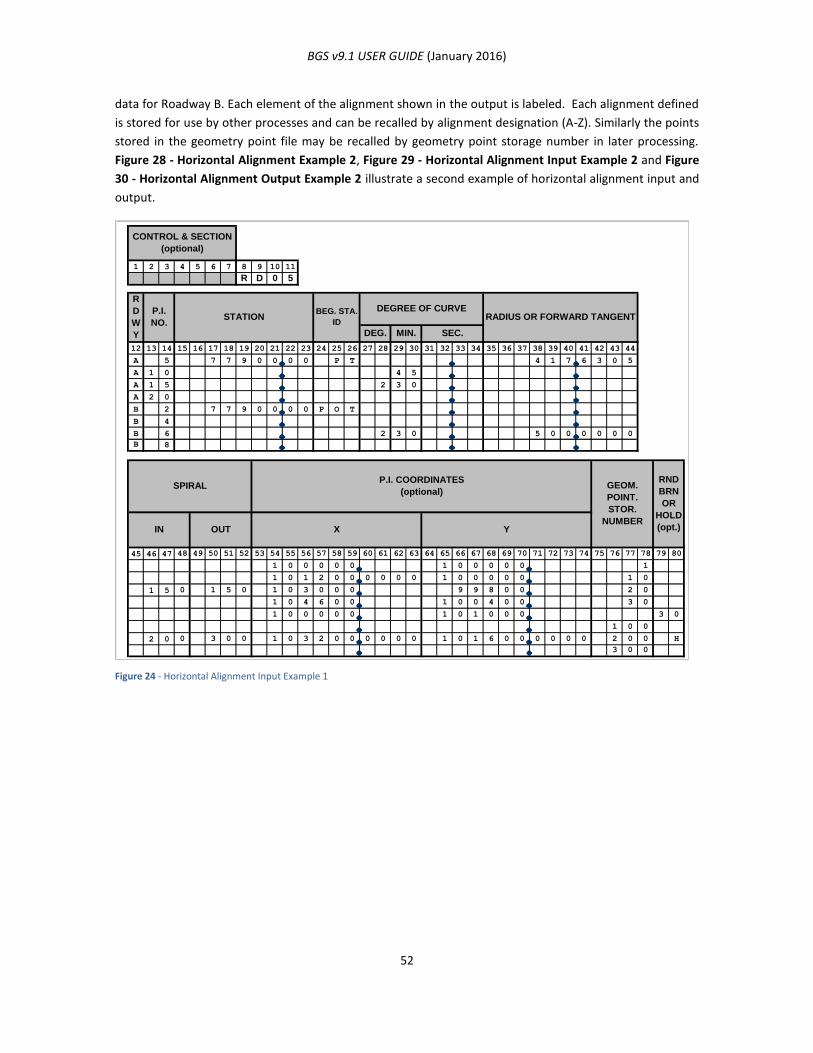
BGS v9.1 USER GUIDE (January 2016)
52
data for Roadway B. Each element of the alignment shown in the output is labeled. Each alignment defined
is stored for use by other processes and can be recalled by alignment designation (A-Z). Similarly the points
stored in the geometry point file may be recalled by geometry point storage number in later processing.
Figure 28 - Horizontal Alignment Example 2, Figure 29 - Horizontal Alignment Input Example 2 and Figure
30 - Horizontal Alignment Output Example 2 illustrate a second example of horizontal alignment input and
output.
Figure 24 - Horizontal Alignment Input Example 1
1 2 3 4 5 6 7 8 9 10 11
R D 0 5
12 13 14 15 16 17 18 19 20 21 22 23 24 25 26 27 28 29 30 31 32 33 34 35 36 37 38 39 40 41 42 43 44
A 5 7 7 9 0 0 0 0 P T 4 1 7 6 3 0 5
A 1 0 4 5
A 1 5 2 3 0
A 2 0
B 2 7 7 9 0 0 0 0 P O T
B 4
B 6 2 3 0 5 0 0 0 0 0 0
B 8
45 46 47 48 49 50 51 52 53 54 55 56 57 58 59 60 61 62 63 64 65 66 67 68 69 70 71 72 73 74 75 76 77 78 79 80
1 0 0 0 0 0 1 0 0 0 0 0 1
1 0 1 2 0 0 0 0 0 0 1 0 0 0 0 0 1 0
1 5 0 1 5 0 1 0 3 0 0 0 9 9 8 0 0 2 0
1 0 4 6 0 0 1 0 0 4 0 0 3 0
1 0 0 0 0 0 1 0 1 0 0 0 3 0
1 0 0
2 0 0 3 0 0 1 0 3 2 0 0 0 0 0 0 1 0 1 6 0 0 0 0 0 0 2 0 0 H
3 0 0
CONTROL & SECTION
(optional)
SPIRALP.I. COORDINATES
(optional)
IN OUT X Y
R
D
W
Y
P.I.
NO.RADIUS OR FORWARD TANGENTSTATION
GEOM.
POINT.
STOR.
NUMBER
RND
BRN
OR
HOLD
(opt.)
BEG. STA.
ID
DEGREE OF CURVE
DEG. MIN. SEC.

BGS v9.1 USER GUIDE (January 2016)
53
Figure 25 - Spiral Curve Data Output
The system allows curves to be defined either by degree of curve (for data using English coordinates) or
radius (for data using either English or metric coordinates). Previously stored point numbers can be entered
in lieu of the PI coordinates. The system can also round the bearings of tangents, accept special cases for
the starting point, handle equations and store PI coordinates as geometry points. Alignments may also be
updated partially or completely.
T
X
U
S.C
.
T.S
.
P.I.
YD.E.
LS (in Spiral)
LS (out S
piral)
L
V
P.I. Angle
C.S
.
S.T.
1) T.S.,S.C., P.I., C.S., S.T. Stations
2) Tangent (T)
3) Length of Spiral (LS)
4) Delta Angle of Spiral (DE)
5) P.I. Angle (Intersection Angle Between Tangents of Entire Curve)
6) Degree of Simple Curve (D)
7) Long Tangent Distance of Spiral Only (U)
8) Short Tangent Distance of Spiral Only (V)
9) Distance From the T.S. or S.T. Along the Main Tangent Line Towards
the Main P.I. (X)
10) Perpendicular Distance From the ‘X’ On the Main Tangent to
Establish the .S. or S.C. (Y)
11) Length of the Circular Curve (L)
12) Radius of the circular Curve (R)
13) Coordinates of the T.S., S.C., P.I., C.S. and S.T.
14) Bearing of the Tangents

BGS v9.1 USER GUIDE (January 2016)
54
Figure 26 - Horizontal Alignment Output for Roadway A
Note 1: Refer to Figure 25 - Spiral Curve Data Output for identification.
PI
779+00.0000 PT
782+59.2582 PC
786+82.3695 PI
791+04.6171 PT
798+69.4621 TS
800+19.4621 SC
804+92.5829 PI
809+45.3116 CS
810+95.3116 ST
821+80.9916
100000.0000
100417.6305
100776.8887
101200.0000
101620.5234
102380.6904
102529.9377
103000.0000
103442.4373
103583.4461
104600.0000
100000.0000
100000.0000
100000.0000
100000.0000
99953.2752
99868.8122
99853.8753
99800.0000
99967.6614
100018.7923
100400.0000
100.0056 U
149.9839 X
149.9839 X
100.0056 U
50.0051 V
1.6361 Y
1.6361 Y
50.0051 V
417.6305 T
1200.0000 FT.
423.1113 T
845.3589 L
1811.0770 FT.
623.1207 T
150.0000 LS
925.8495 L
150.0000 LS
623.1207 T
1708.8007 FT.
90 00 00.00 E
00 45 00.00 D
06 20 24.69 RT
7639.4373 R
83 39 35.31 E
01 52 30.00 DE
02 30 00.00 D
26 53 46.45 LT
2291.8312 R
01 52 30.00 DE
69 26 38.24 E
5
10
15
20
N
S
N
COMPUTATIONS BASED ON ARC DEFINITION
HORIZONTAL ALIGNMENT LISTFOR ROADWAY A
P.I. X Ybeginning station
degree of curve
radius
delta angle tangentlength
length ofcurve
forward tangent distance
beginning coordinates
coordinates of beginningstation
See Note 1
in spiraldelta angle
first tangentlength
length of simplecurve
in spirallength
computed endingstations
bearing and distancebetween PI’s
degree of curve and radius ofsimple curve
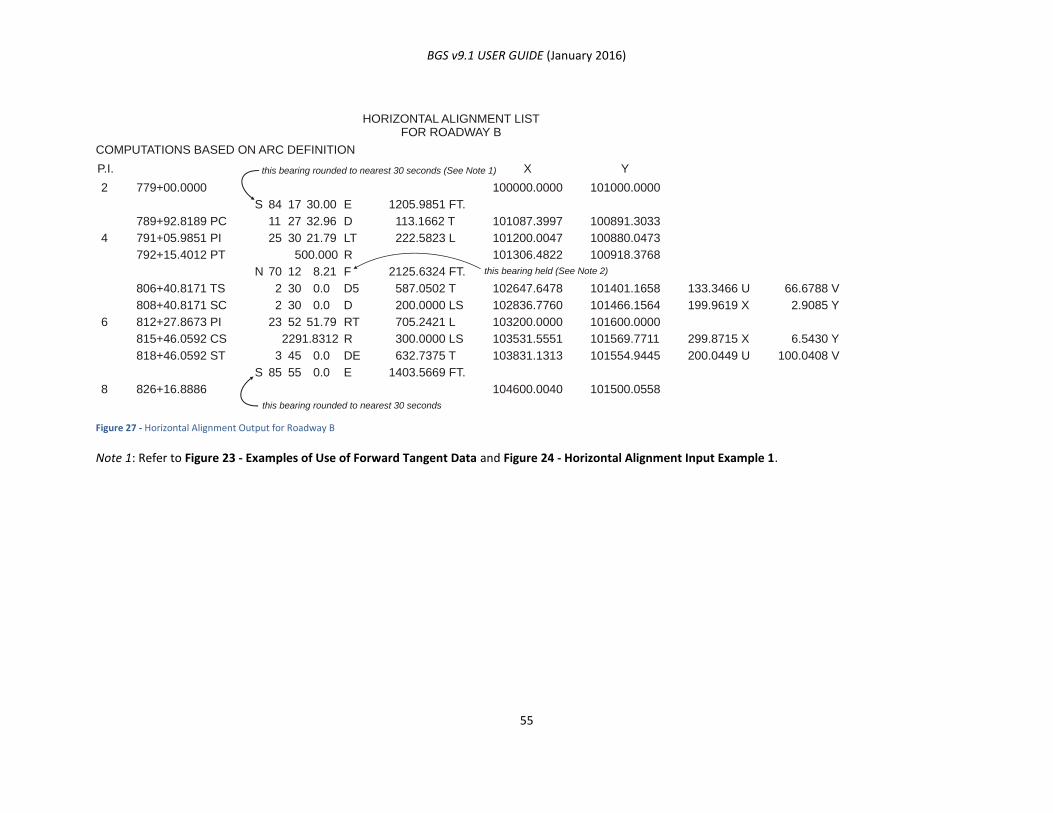
BGS v9.1 USER GUIDE (January 2016)
55
Figure 27 - Horizontal Alignment Output for Roadway B
Note 1: Refer to Figure 23 - Examples of Use of Forward Tangent Data and Figure 24 - Horizontal Alignment Input Example 1.
779+00.0000
789+92.8189 PC
791+05.9851 PI
792+15.4012 PT
806+40.8171 TS
808+40.8171 SC
812+27.8673 PI
815+46.0592 CS
818+46.0592 ST
826+16.8886
100000.0000
101087.3997
101200.0047
101306.4822
102647.6478
102836.7760
103200.0000
103531.5551
103831.1313
104600.0040
101000.0000
100891.3033
100880.0473
100918.3768
101401.1658
101466.1564
101600.0000
101569.7711
101554.9445
101500.0558
133.3466 U
199.9619 X
299.8715 X
200.0449 U
66.6788 V
2.9085 Y
6.5430 Y
100.0408 V
1205.9851 FT.
113.1662 T
222.5823 L
2125.6324 FT.
587.0502 T
200.0000 LS
705.2421 L
300.0000 LS
632.7375 T
1403.5669 FT.
84 17 30.00 E
11 27 32.96 D
25 30 21.79 LT
500.000 R
70 12 8.21 F
2 30 0.0 D5
23 52 51.79 RT
2291.8312 R
3 45 0.0 DE
85 55 0.0 E
2 30 0.0 D
2
4
6
8
S
N
S
COMPUTATIONS BASED ON ARC DEFINITION
HORIZONTAL ALIGNMENT LISTFOR ROADWAY B
P.I. X Ythis bearing rounded to nearest 30 seconds (See Note 1)
this bearing rounded to nearest 30 seconds
this bearing held (See Note 2)
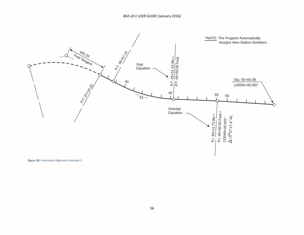
BGS v9.1 USER GUIDE (January 2016)
56
Figure 28 - Horizontal Alignment Example 2
Fwd Tangent
405.33
40
4550 50
P.T.
37+16.3
2
P.T.
38+67.1
5
GapEquation
Sta. 55+00.08
*NOTE: The Program Automatically
Assigns New Station Numbers.
(10055+00.08)*
OverlapEquation
P.T
. 45
+3
1.5
3 B
k.=
P.T
. 4
5+
50.0
0 F
wd
P.I
. 5
0+
11
.73
Bk.=
P.I
. 4
9+
00
.00
Fw
d.=
(10
049
+00
.00
)*
=0
57
’17
.4”
Rt.
.

BGS v9.1 USER GUIDE (January 2016)
57
ALTERNATE HORIZONTAL ALIGNMENT (RD06) DATA INPUT
FUNCTION
The Card 3 - Alternate Horizontal Alignment Data Input Card (RD06) establishes the horizontal alignment
of one or more roadways with accommodation made for more precise input of a spiral.
USAGE
The RD06 card is essentially the same as the RD05 card previously mentioned. The only difference between
these input cards is the location of the implied decimal for the spiral in and out lengths. The RD05 card uses
an F4.0 format for the input spiral length (providing for lengths up to 9999.) while the RD06 card uses an
F4.1 format for the input spiral length (providing for lengths to only 999.9).
In other words, with the RD05 input card and the F4.0 formatted spiral length, the user is allowed to enter
up to four decimal digits (e.g. 3422) for either spiral length, or even 34.2, if the decimal point is typed in;
but, the user cannot use this card to input the value 342.2 because there would be no room for the decimal
point. With the RD06 input card and the F4.1 formatted spiral length, there is an implicit decimal between
columns 47 and 48 and between columns 51 and 52. This way, the user is able to enter the value 3422 in
columns 45-48 and/or 48-52, and the number entered is read as 342.2.
Card 3 - Alternate Horizontal Alignment Data Input Card
ARGUMENTS
See Horizontal Alignment (RD05) Data Input.
PARALLEL ALIGNMENT (RD16) DATA INPUT
FUNCTION
The RD16 command establishes an offset alignment parallel to an existing alignment(s).
1 2 3 4 5 6 7 8 9 10 11
R D 0 6
12 13 14 15 16 17 18 19 20 21 22 23 24 25 26 27 28 29 30 31 32 33 34 35 36 37 38 39 40 41 42 43 44
45 46 47 48 49 50 51 52 53 54 55 56 57 58 59 60 61 62 63 64 65 66 67 68 69 70 71 72 73 74 75 76 77 78 79 80
CONTROL & SECTION
(optional)
SPIRALP.I. COORDINATES
(optional)GEOM.
POINT.
STOR.
NUMBERYXOUTIN
R
D
W
Y
P.I.
NO.RADIUS OR FORWARD TANGENTSTATION
RND
BRN
OR
HOLD
(opt.)
BEG. STA.
ID
DEGREE OF CURVE
DEG. MIN. SEC.
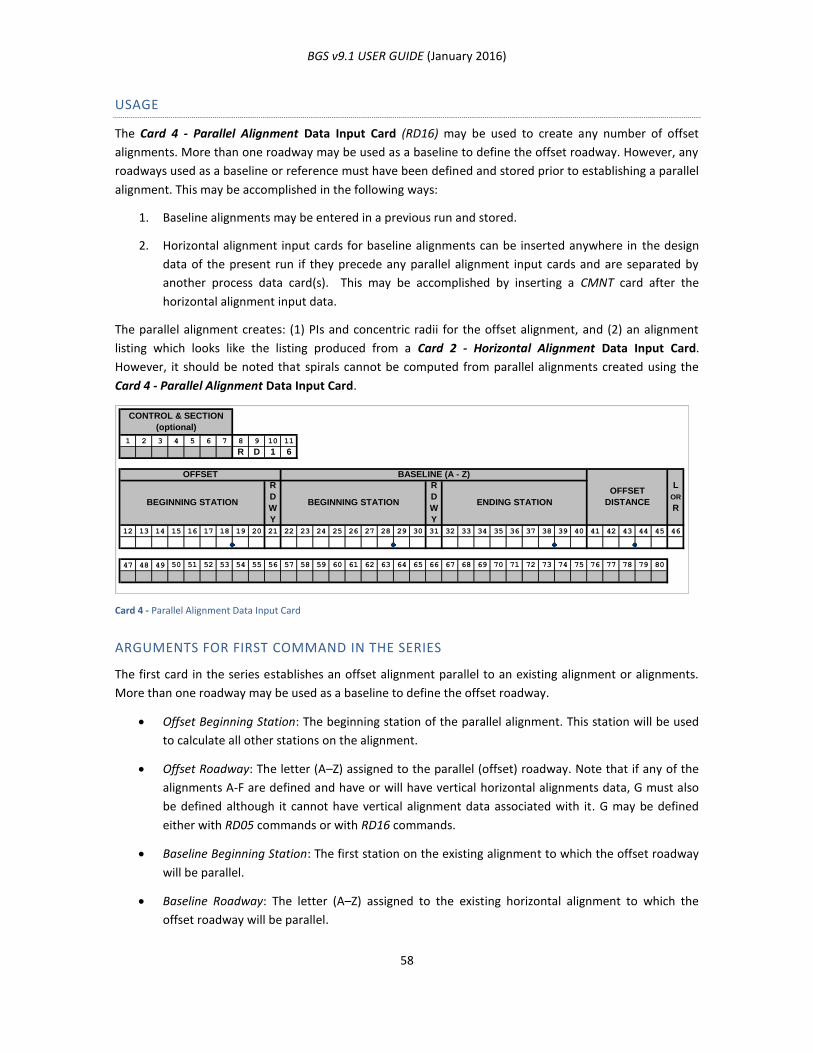
BGS v9.1 USER GUIDE (January 2016)
58
USAGE
The Card 4 - Parallel Alignment Data Input Card (RD16) may be used to create any number of offset
alignments. More than one roadway may be used as a baseline to define the offset roadway. However, any
roadways used as a baseline or reference must have been defined and stored prior to establishing a parallel
alignment. This may be accomplished in the following ways:
1. Baseline alignments may be entered in a previous run and stored.
2. Horizontal alignment input cards for baseline alignments can be inserted anywhere in the design
data of the present run if they precede any parallel alignment input cards and are separated by
another process data card(s). This may be accomplished by inserting a CMNT card after the
horizontal alignment input data.
The parallel alignment creates: (1) PIs and concentric radii for the offset alignment, and (2) an alignment
listing which looks like the listing produced from a Card 2 - Horizontal Alignment Data Input Card.
However, it should be noted that spirals cannot be computed from parallel alignments created using the
Card 4 - Parallel Alignment Data Input Card.
Card 4 - Parallel Alignment Data Input Card
ARGUMENTS FOR FIRST COMMAND IN THE SERIES
The first card in the series establishes an offset alignment parallel to an existing alignment or alignments.
More than one roadway may be used as a baseline to define the offset roadway.
Offset Beginning Station: The beginning station of the parallel alignment. This station will be used
to calculate all other stations on the alignment.
Offset Roadway: The letter (A–Z) assigned to the parallel (offset) roadway. Note that if any of the
alignments A-F are defined and have or will have vertical horizontal alignments data, G must also
be defined although it cannot have vertical alignment data associated with it. G may be defined
either with RD05 commands or with RD16 commands.
Baseline Beginning Station: The first station on the existing alignment to which the offset roadway
will be parallel.
Baseline Roadway: The letter (A–Z) assigned to the existing horizontal alignment to which the
offset roadway will be parallel.
1 2 3 4 5 6 7 8 9 10 11
R D 1 6
12 13 14 15 16 17 18 19 20 21 22 23 24 25 26 27 28 29 30 31 32 33 34 35 36 37 38 39 40 41 42 43 44 45 46
47 48 49 50 51 52 53 54 55 56 57 58 59 60 61 62 63 64 65 66 67 68 69 70 71 72 73 74 75 76 77 78 79 80
ENDING STATION
OFFSET
DISTANCE
L
OR
R
BASELINE (A - Z)
R
D
W
Y
R
D
W
Y
CONTROL & SECTION
(optional)
OFFSET
BEGINNING STATION BEGINNING STATION

BGS v9.1 USER GUIDE (January 2016)
59
Baseline Ending Station: The last station on the existing alignment to which the offset roadway will
be parallel.
Offset Distance: The perpendicular distance from the baseline roadway to the offset roadway.
L or R: L if the offset roadway is to the left of the baseline roadway in the direction of increasing
stations, and R if it is to the right.
Note: This card may stand alone or be followed by one or more succeeding RD16 cards for the same parallel
roadway. Succeeding cards may refer to the same or other existing alignments. After the parallel alignment
is created, it is treated as an ordinary horizontal alignment. The user may define profile grade and
templates for the parallel alignment (unless it is alignment G), plot the alignment, and perform other
functions as for an ordinary horizontal alignment.
ARGUMENTS FOR OPTIONAL SUCCEEDING COMMAND(S) IN THE SERIES
This (these) card(s) in the series establishes a segment of the parallel alignment succeeding the segment
defined on the previous command.
Offset Roadway: The letter (A–Z) assigned to the parallel (offset) roadway in the preceding
command. Note that if any of the horizontal alignments A-F are defined and have or will have
vertical alignment data, G must also be defined although it cannot have vertical alignment data
associated with it. G may be defined either with RD05 commands or with RD16 commands.
Baseline Beginning Station: The first station on an existing alignment to which this segment of the
offset roadway will be parallel. The existing alignment may or may not be the same as in the
preceding command.
Baseline Roadway: The letter (A–Z) assigned to the existing alignment to which this segment of the
offset roadway will be parallel.
Baseline Ending Station: The last station on the existing alignment to which this segment of the
offset roadway will be parallel.
Offset Distance: The distance from the baseline roadway to this segment of the offset roadway.
L or R: L if the offset roadway is to the left of the baseline roadway in the direction of increasing
stations, and R if it is to the right.
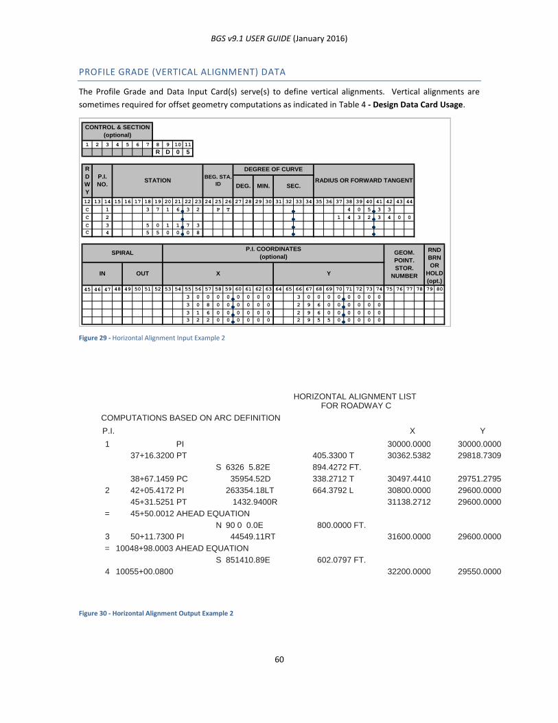
BGS v9.1 USER GUIDE (January 2016)
60
PROFILE GRADE (VERTICAL ALIGNMENT) DATA
The Profile Grade and Data Input Card(s) serve(s) to define vertical alignments. Vertical alignments are
sometimes required for offset geometry computations as indicated in Table 4 - Design Data Card Usage.
Figure 29 - Horizontal Alignment Input Example 2
Figure 30 - Horizontal Alignment Output Example 2
1 2 3 4 5 6 7 8 9 10 11
R D 0 5
12 13 14 15 16 17 18 19 20 21 22 23 24 25 26 27 28 29 30 31 32 33 34 35 36 37 38 39 40 41 42 43 44
C 1 3 7 1 6 3 2 P T 4 0 5 3 3
C 2 1 4 3 2 3 4 0 0
C 3 5 0 1 1 7 3
C 4 5 5 0 0 0 8
45 46 47 48 49 50 51 52 53 54 55 56 57 58 59 60 61 62 63 64 65 66 67 68 69 70 71 72 73 74 75 76 77 78 79 80
3 0 0 0 0 0 0 0 0 3 0 0 0 0 0 0 0 0
3 0 8 0 0 0 0 0 0 2 9 6 0 0 0 0 0 0
3 1 6 0 0 0 0 0 0 2 9 6 0 0 0 0 0 0
3 2 2 0 0 0 0 0 0 2 9 5 5 0 0 0 0 0
RADIUS OR FORWARD TANGENT
R
D
W
Y
P.I.
NO.
BEG. STA.
ID
DEGREE OF CURVE
DEG. MIN. SEC.
Y
GEOM.
POINT.
STOR.
NUMBER
RND
BRN
OR
HOLD
(opt.)
CONTROL & SECTION
(optional)
SPIRAL
IN OUT
STATION
P.I. COORDINATES
(optional)
X
PI
38+67.1459 PC
42+05.4172 PI
45+31.5251 PT
50+11.7300 PI
37+16.3200 PT
45+50.0012 AHEAD EQUATION
30000.0000
30362.5382
30497.4410
30800.0000
31138.2712
31600.0000
32200.0000
30000.0000
29818.7309
29751.2795
29600.0000
29600.0000
29600.0000
29550.0000
405.3300 T
894.4272 FT.
338.2712 T
664.3792 L
800.0000 FT.
602.0797 FT.
6326 5.82E
35954.52D
263354.18LT
1432.9400R
90 0 0.0E
44549.11RT
851410.89E
1
2
=
3
=
4
S
N
S
COMPUTATIONS BASED ON ARC DEFINITION
HORIZONTAL ALIGNMENT LIST FOR ROADWAY C
P.I. X Y
10048+98.0003 AHEAD EQUATION
10055+00.0800

BGS v9.1 USER GUIDE (January 2016)
61
FUNCTION
This command establishes the beginning point on a vertical alignment (profile grade).
USAGE
A vertical alignment must be stored for each applicable roadway if elevation computations are to be made.
Storage is accomplished by entering elevation data for each PI and vertical curve parameters where
applicable. In all cases, the first and last vertical curve length for an alignment must be zero. Sufficient
vertical alignment data must be provided to adequately describe the alignment in design areas. A vertical
curve may be either symmetrical or asymmetrical as indicated below:
Figure 31 - Vertical Curve Symmetry
Profile grades may be modified by an elevation correction as needed.
Figure 32 - Elevation Correction
A previously stored vertical alignment for any roadway may be revised either partially or completely.
Procedures for revising vertical alignment data are discussed in this chapter under the heading “Updating
Design Data.”
The Card 5 - Profile Grade Data Input Card (RD10) is related to the Card 6 - Template Data Input Card
(RD30) since it determines the elevation of the template section. The point at which the profile grade is
applied to the template section is indicated on the RD30 Card.
same distance
SYMMETRICAL ASYMMETRICAL
different distance
this distance is enteredboth distances
are entered
amount ofelevationcorrection
elevation correction applied at PI is in effectfor distance
thisthis
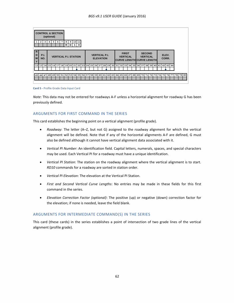
BGS v9.1 USER GUIDE (January 2016)
62
Card 5 - Profile Grade Data Input Card
Note: This data may not be entered for roadways A-F unless a horizontal alignment for roadway G has been
previously defined.
ARGUMENTS FOR FIRST COMMAND IN THE SERIES
This card establishes the beginning point on a vertical alignment (profile grade).
Roadway: The letter (A–Z, but not G) assigned to the roadway alignment for which the vertical
alignment will be defined. Note that if any of the horizontal alignments A-F are defined, G must
also be defined although it cannot have vertical alignment data associated with it.
Vertical PI Number: An identification field. Capital letters, numerals, spaces, and special characters
may be used. Each Vertical PI for a roadway must have a unique identification.
Vertical PI Station: The station on the roadway alignment where the vertical alignment is to start.
RD10 commands for a roadway are sorted in station order.
Vertical PI Elevation: The elevation at the Vertical PI Station.
First and Second Vertical Curve Lengths: No entries may be made in these fields for this first
command in the series.
Elevation Correction Factor (optional): The positive (up) or negative (down) correction factor for
the elevation; if none is needed, leave the field blank.
ARGUMENTS FOR INTERMEDIATE COMMAND(S) IN THE SERIES
This card (these cards) in the series establishes a point of intersection of two grade lines of the vertical
alignment (profile grade).
1 2 3 4 5 6 7 8 9 10 11
R D 1 0
R
D
W
Y
12 13 14 15 16 17 18 19 20 21 22 23 24 25 26 27 28 29 30 31 32 33 34 35 36 37 38 39 40 41 42 43 44
45 46 47 48 49 50 51 52 53 54 55 56 57 58 59 60 61 62 63 64 65 66 67 68 69 70 71 72 73 74 75 76 77 78 79 80
CONTROL & SECTION
(optional)
P.I.
NO.VERTICAL P.I. STATION
VERTICAL P.I.
ELEVATION
FIRST
VERTICAL
CURVE LENGTH
SECOND
VERTICAL
CURVE LENGTH
ELEV.
CORR.

BGS v9.1 USER GUIDE (January 2016)
63
Roadway: The letter (A–Z, but not G) assigned to the roadway alignment for which the vertical
alignment will be defined. Note that if any of horizontal alignments A-F are defined, G must also be
defined though it cannot have vertical alignment data associated with it.
Vertical PI Number: An identification field. Capital letters, numerals, spaces and special characters
may be used. Each Vertical PI for a roadway must have a unique identification.
Vertical PI Station: The station on the roadway alignment where two grade lines intersect. RD10
commands for a roadway are sorted by PI stations.
Elevation: The elevation at the Vertical PI Station.
First and Second Vertical Curve Lengths: If the vertical curve is symmetric, enter the entire vertical
curve length as the First Vertical Curve Length—half of it will be applied before the PI station and
half after. The second vertical curve length is omitted. If the vertical curve is asymmetric, the First
Vertical Curve Length will be applied before the PI station and the Second Vertical Curve Length
will be applied after it.
ARGUMENTS FOR FINAL COMMAND IN THE SERIES
This final card in the series establishes the ending point on the vertical alignment (profile grade).
Roadway: The letter (A–Z, but not G) assigned to the roadway alignment for which the vertical
alignment will be defined. Vertical alignment data cannot be defined for roadway G.
Vertical PI Number: An identification field. Capital letters, numerals, spaces, and special characters
may be used. Each Vertical PI for a roadway must have a unique identification.
Vertical PI Station: The station on the roadway alignment where the defined vertical alignment is
to end. RD10 commands for a roadway are sorted by PI stations.
Vertical PI Elevation: The elevation at the Vertical PI Station.
First and Second Vertical Curve Lengths: No entries may be made in these fields for this last
command in the series.
Elevation Correction Factor (optional): The positive (up) or negative (down) correction factor for
the elevation; if none is needed, leave the field blank.
TEMPLATE DATA
FUNCTION
This command defines a roadway template for a single station on a roadway.

BGS v9.1 USER GUIDE (January 2016)
64
USAGE
Makes use of the Store/Recall feature. If the desired shape is already stored, the number for the shape is all
that is needed. If the desired shape has not been stored, defining it on the card will cause it to be stored by
the number indicated.
Template shapes are made up of a series of road segments with ridge points at each end of each road
segment.
Figure 33 - Template Shape Definition
A road segment may be defined in one of two methods:
Table 5 - Roadway Segment Definition
Method 1
Give: Horizontal distance in feet; slope in feet
per foot.
This method may be one of two options:
(1) Blank – normal superelevation is applied to
the segment
(2) H – superelevation is not applied to
the segment
Method 2
Give: Vertical distance in feet; slope in feet per
foot.
This method must be option V. No super-
elevation is applied to the segment.
NOTE: Slopes extending upward to the right
are positive.
A series of RD30 commands establishes the entire roadway surface. Each RD30 command consists of a
roadway letter, a station number, a storage/recall number, and a template shape (optional). A template
Road Segments
Ridge Points
Maximum number of segments = 15 Segments and ridge points are numbered consecutively left to right.
Distance
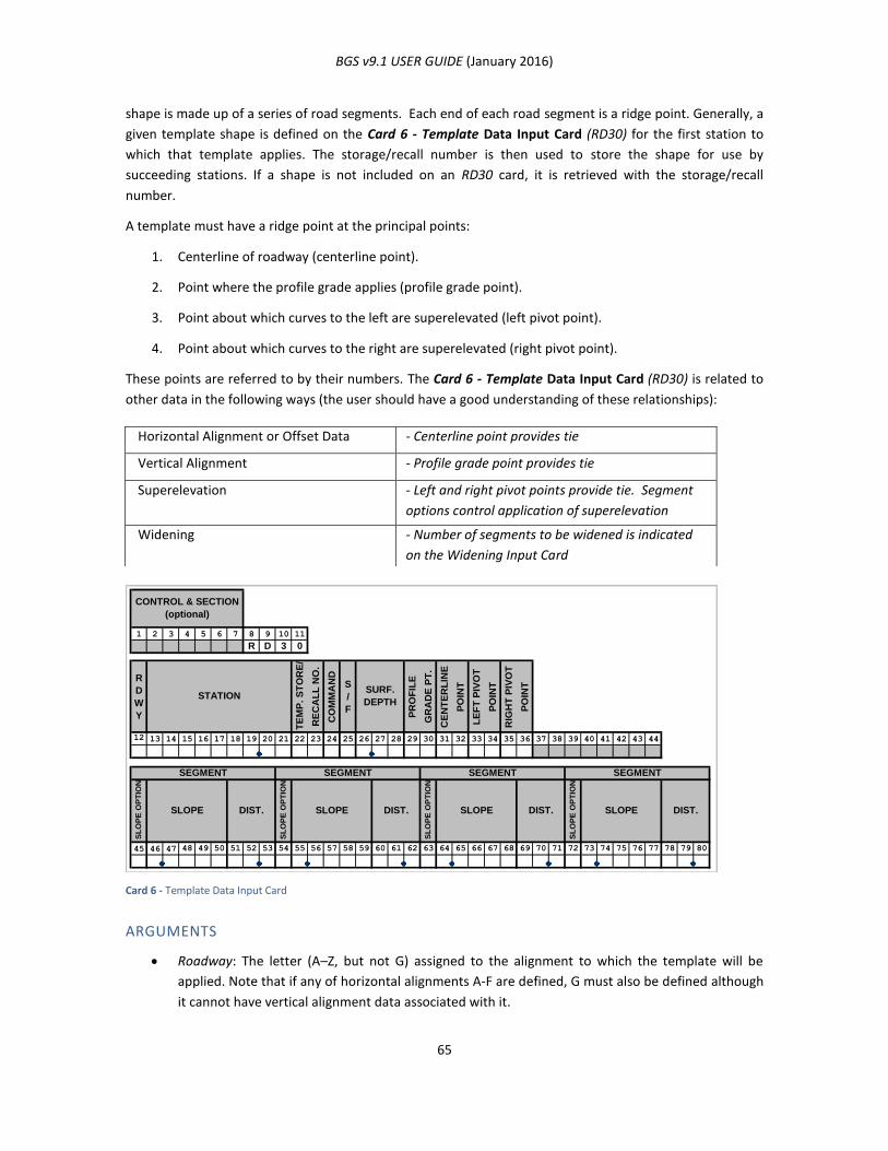
BGS v9.1 USER GUIDE (January 2016)
65
shape is made up of a series of road segments. Each end of each road segment is a ridge point. Generally, a
given template shape is defined on the Card 6 - Template Data Input Card (RD30) for the first station to
which that template applies. The storage/recall number is then used to store the shape for use by
succeeding stations. If a shape is not included on an RD30 card, it is retrieved with the storage/recall
number.
A template must have a ridge point at the principal points:
1. Centerline of roadway (centerline point).
2. Point where the profile grade applies (profile grade point).
3. Point about which curves to the left are superelevated (left pivot point).
4. Point about which curves to the right are superelevated (right pivot point).
These points are referred to by their numbers. The Card 6 - Template Data Input Card (RD30) is related to
other data in the following ways (the user should have a good understanding of these relationships):
Card 6 - Template Data Input Card
ARGUMENTS
Roadway: The letter (A–Z, but not G) assigned to the alignment to which the template will be
applied. Note that if any of horizontal alignments A-F are defined, G must also be defined although
it cannot have vertical alignment data associated with it.
1 2 3 4 5 6 7 8 9 10 11
R D 3 0
R
D
W
Y
TE
MP
. S
TO
RE
/
RE
CA
LL
NO
.
CO
MM
AN
D
S
/
F
PR
OF
ILE
GR
AD
E P
T.
CE
NT
ER
LIN
E
PO
INT
LE
FT
PIV
OT
PO
INT
RIG
HT
PIV
OT
PO
INT
12 13 14 15 16 17 18 19 20 21 22 23 24 25 26 27 28 29 30 31 32 33 34 35 36 37 38 39 40 41 42 43 44
45 46 47 48 49 50 51 52 53 54 55 56 57 58 59 60 61 62 63 64 65 66 67 68 69 70 71 72 73 74 75 76 77 78 79 80
SL
OP
E O
PT
ION
SLOPE DIST.
SEGMENT SEGMENT SEGMENT SEGMENT
SL
OP
E O
PT
ION
SLOPE DIST. SLOPE DIST.
CONTROL & SECTION
(optional)
STATIONSURF.
DEPTH
SL
OP
E O
PT
ION
SLOPE DIST.
SL
OP
E O
PT
ION
Horizontal Alignment or Offset Data - Centerline point provides tie
Vertical Alignment - Profile grade point provides tie
Superelevation - Left and right pivot points provide tie. Segment
options control application of superelevation
Widening - Number of segments to be widened is indicated
on the Widening Input Card
BGS v9.1 USER GUIDE (January 2016)
66
Station: The station on the alignment where the template will be applied. Let templates be defined
at the stations at either end of a section of the alignment. Then, at any given station between
these stations, the system interpolates a template from the defined templates. For this
interpolation to be successful, the two templates must have the same number of points and the
same principal points: profile grade, centerline, and left and right pivot points. To change to a
template with a different number of points or with different principal points, specify a template
compatible with the previous template at a station 0.01 ft. or 0.001 meters behind the new
template station.
Storage/Recall Number: The number used to store the template shape if entries are made in the
subsequent fields of the command. If no entries are made in the subsequent fields, the
storage/recall number is the number used to retrieve the template shape.
Line Number (Command): The number of a line used to enter the segments which define the shape
for the template. For each template, as many as four lines may be used to enter from 1 to 15
segments. These segments must be entered consecutively from left to right, facing in the direction
of increasing stations.
S/F: Enter S to indicate that a subgrade template is being defined and F to indicate a finished grade
template.
Surface Depth: If a finished grade template is being defined, enter the finished to subgrade depth
here.
Profile Grade Point: The number of the ridge point, counting from left to right along the template,
which will be used as the profile grade point. Note that this and one or more of the other principal
points may share the same ridge point.
Centerline Point: The number of the ridge point that will be used as the centerline point. Note that
this and one or more of the other principal points may share the same ridge point.
Left Pivot Point: The number of the ridge point that will be used as the left superelevation pivot
point. Note that this and one or more of the other principal points may share the same ridge point.
Right Pivot Point: The number of the ridge point that will be used as the right superelevation pivot
point. Note that this and one or more of the other principal points may share the same ridge point.
Segment: The following defines one of the segments of the template:
Slope Option: If this is blank, the distance is the horizontal distance of the segment and
superelevation is applied to the segment. If this is H, the distance is the horizontal distance
and superelevation is not applied. If this is V, the distance is the vertical distance and
superelevation is not applied.
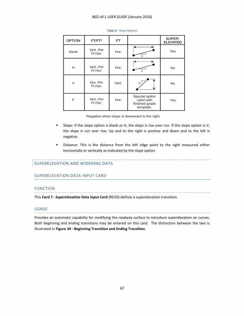
BGS v9.1 USER GUIDE (January 2016)
67
Table 6 - Slope Options
Slope: If the slope option is blank or H, the slope is rise over run. If the slope option is V,
the slope is run over rise. Up and to the right is positive and down and to the left is
negative.
Distance: This is the distance from the left ridge point to the right measured either
horizontally or vertically as indicated by the slope option.
SUPERELEVATION AND WIDENING DATA
SUPERELEVATION DATA INPUT CARD
FUNCTION
This Card 7 - Superelevation Data Input Card (RD20) defines a superelevation transition.
USAGE
Provides an automatic capability for modifying the roadway surface to introduce superelevation on curves.
Both beginning and ending transitions may be entered on this card. The distinction between the two is
illustrated in Figure 34 - Beginning Transition and Ending Transition.
OPTIONOPTION
blank
H
V
F
FT/FT*FT/FT*
Vert. PerFt Hor.
Vert. PerFt Hor.
Hor. PerFt Hor.
Vert. PerFt Hor.
FTFT
Hor.
Hor.
Vert.
Hor.
SUPER-ELEVATED
SUPER-ELEVATED
Yes
No
No
Yes
*Negative when slope is downward to the right.
Special optionused with
finished gradetemplate.
1
1
1
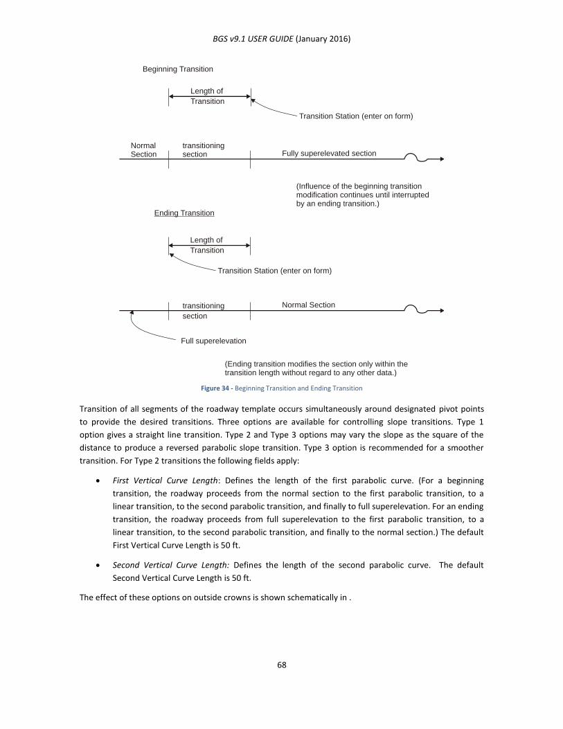
BGS v9.1 USER GUIDE (January 2016)
68
Figure 34 - Beginning Transition and Ending Transition
Transition of all segments of the roadway template occurs simultaneously around designated pivot points
to provide the desired transitions. Three options are available for controlling slope transitions. Type 1
option gives a straight line transition. Type 2 and Type 3 options may vary the slope as the square of the
distance to produce a reversed parabolic slope transition. Type 3 option is recommended for a smoother
transition. For Type 2 transitions the following fields apply:
First Vertical Curve Length: Defines the length of the first parabolic curve. (For a beginning
transition, the roadway proceeds from the normal section to the first parabolic transition, to a
linear transition, to the second parabolic transition, and finally to full superelevation. For an ending
transition, the roadway proceeds from full superelevation to the first parabolic transition, to a
linear transition, to the second parabolic transition, and finally to the normal section.) The default
First Vertical Curve Length is 50 ft.
Second Vertical Curve Length: Defines the length of the second parabolic curve. The default
Second Vertical Curve Length is 50 ft.
The effect of these options on outside crowns is shown schematically in .
Beginning Transition
Transition Station (enter on form)
NormalSection
transitioningsection Fully superelevated section
(Influence of the beginning transitionmodification continues until interruptedby an ending transition.)
Length of
Transition
Full superelevation
Transition Station (enter on form)
transitioning
section
Normal Section
Ending Transition
(Ending transition modifies the section only within thetransition length without regard to any other data.)
Length of
Transition
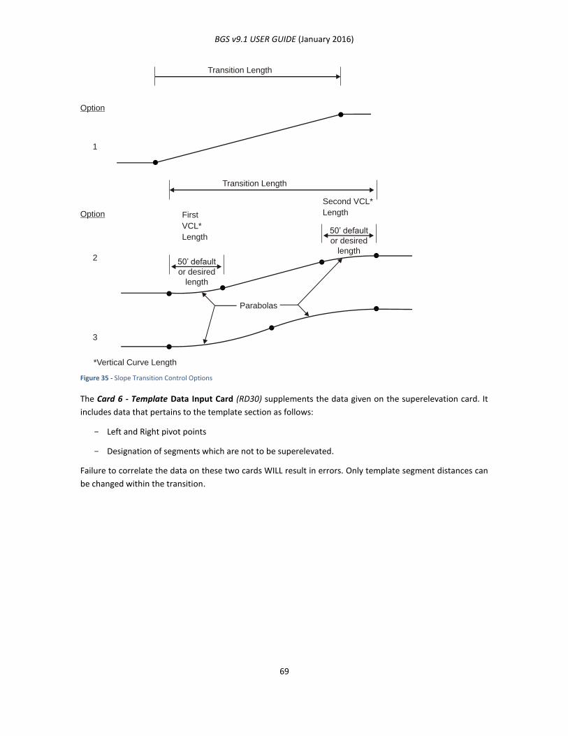
BGS v9.1 USER GUIDE (January 2016)
69
Figure 35 - Slope Transition Control Options
The Card 6 - Template Data Input Card (RD30) supplements the data given on the superelevation card. It
includes data that pertains to the template section as follows:
- Left and Right pivot points
- Designation of segments which are not to be superelevated.
Failure to correlate the data on these two cards WILL result in errors. Only template segment distances can
be changed within the transition.
1
Option
Transition Length
2
3
Option
Transition Length
Parabolas
First
VCL*
Length
Second VCL*
Length
50’ default
or desired
length
50’ default
or desired
length
*Vertical Curve Length
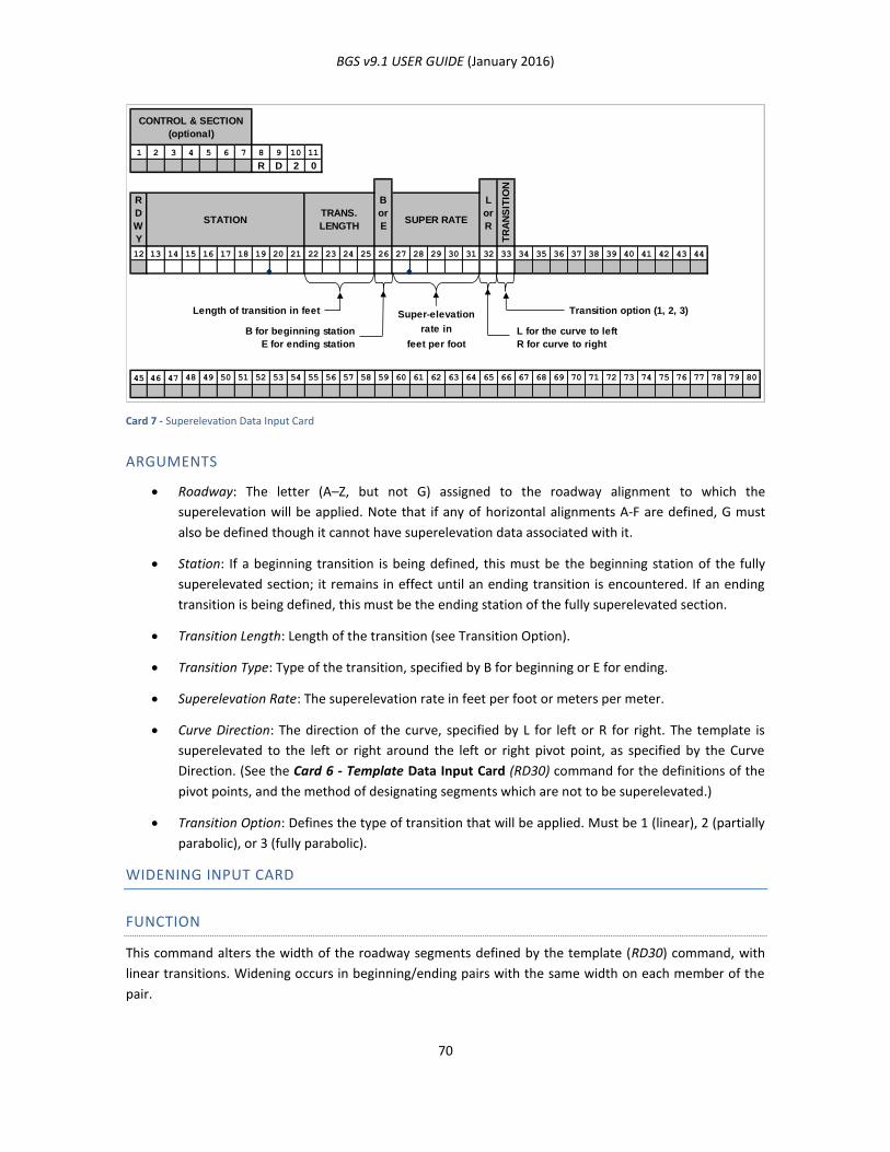
BGS v9.1 USER GUIDE (January 2016)
70
Card 7 - Superelevation Data Input Card
ARGUMENTS
Roadway: The letter (A–Z, but not G) assigned to the roadway alignment to which the
superelevation will be applied. Note that if any of horizontal alignments A-F are defined, G must
also be defined though it cannot have superelevation data associated with it.
Station: If a beginning transition is being defined, this must be the beginning station of the fully
superelevated section; it remains in effect until an ending transition is encountered. If an ending
transition is being defined, this must be the ending station of the fully superelevated section.
Transition Length: Length of the transition (see Transition Option).
Transition Type: Type of the transition, specified by B for beginning or E for ending.
Superelevation Rate: The superelevation rate in feet per foot or meters per meter.
Curve Direction: The direction of the curve, specified by L for left or R for right. The template is
superelevated to the left or right around the left or right pivot point, as specified by the Curve
Direction. (See the Card 6 - Template Data Input Card (RD30) command for the definitions of the
pivot points, and the method of designating segments which are not to be superelevated.)
Transition Option: Defines the type of transition that will be applied. Must be 1 (linear), 2 (partially
parabolic), or 3 (fully parabolic).
WIDENING INPUT CARD
FUNCTION
This command alters the width of the roadway segments defined by the template (RD30) command, with
linear transitions. Widening occurs in beginning/ending pairs with the same width on each member of the
pair.
1 2 3 4 5 6 7 8 9 10 11
R D 2 0
12 13 14 15 16 17 18 19 20 21 22 23 24 25 26 27 28 29 30 31 32 33 34 35 36 37 38 39 40 41 42 43 44
Length of transition in feet Super-elevation Transition option (1, 2, 3)
B for beginning station rate in L for the curve to left
E for ending station feet per foot R for curve to right
45 46 47 48 49 50 51 52 53 54 55 56 57 58 59 60 61 62 63 64 65 66 67 68 69 70 71 72 73 74 75 76 77 78 79 80
TR
AN
SIT
ION
TY
PE
CONTROL & SECTION
(optional)
R
D
W
Y
STATIONTRANS.
LENGTH
B
or
ESUPER RATE
L
or
R
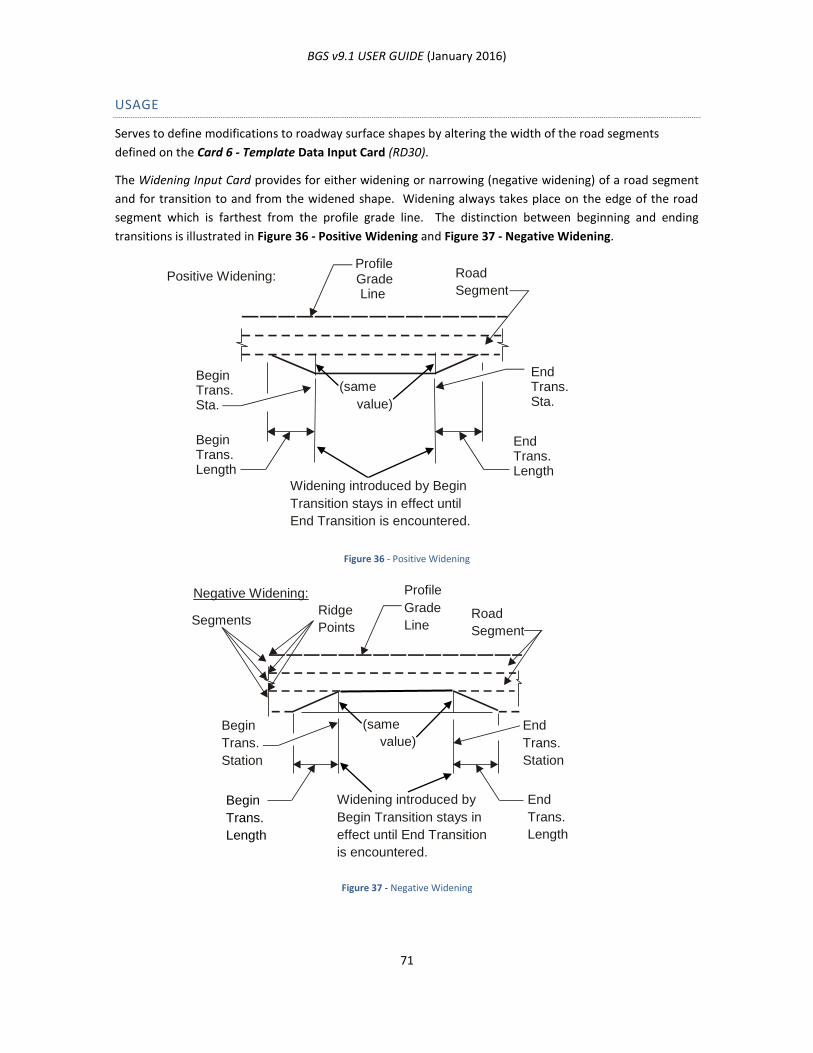
BGS v9.1 USER GUIDE (January 2016)
71
USAGE
Serves to define modifications to roadway surface shapes by altering the width of the road segments
defined on the Card 6 - Template Data Input Card (RD30).
The Widening Input Card provides for either widening or narrowing (negative widening) of a road segment
and for transition to and from the widened shape. Widening always takes place on the edge of the road
segment which is farthest from the profile grade line. The distinction between beginning and ending
transitions is illustrated in Figure 36 - Positive Widening and Figure 37 - Negative Widening.
Figure 36 - Positive Widening
Figure 37 - Negative Widening
Positive Widening: Road
Segment
Profile Grade Line
Begin Trans. Sta.
End Trans. Sta.
Begin Trans. Length
End Trans. Length
Widening introduced by Begin
Transition stays in effect until
End Transition is encountered.
(same value)
Negative Widening:
Road
Segment
Profile
Grade
Line Ridge
Points Segments
Begin
Trans.
Station
End
Trans.
Length
(same
value)
Begin Trans.
Length
End
Trans.
Station
Widening introduced by
Begin Transition stays in
effect until End Transition
is encountered.
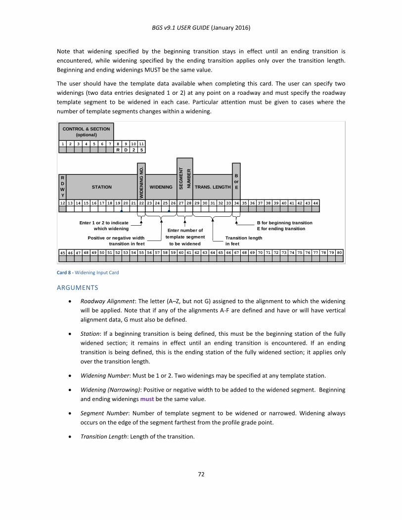
BGS v9.1 USER GUIDE (January 2016)
72
Note that widening specified by the beginning transition stays in effect until an ending transition is
encountered, while widening specified by the ending transition applies only over the transition length.
Beginning and ending widenings MUST be the same value.
The user should have the template data available when completing this card. The user can specify two
widenings (two data entries designated 1 or 2) at any point on a roadway and must specify the roadway
template segment to be widened in each case. Particular attention must be given to cases where the
number of template segments changes within a widening.
Card 8 - Widening Input Card
ARGUMENTS
Roadway Alignment: The letter (A–Z, but not G) assigned to the alignment to which the widening
will be applied. Note that if any of the alignments A-F are defined and have or will have vertical
alignment data, G must also be defined.
Station: If a beginning transition is being defined, this must be the beginning station of the fully
widened section; it remains in effect until an ending transition is encountered. If an ending
transition is being defined, this is the ending station of the fully widened section; it applies only
over the transition length.
Widening Number: Must be 1 or 2. Two widenings may be specified at any template station.
Widening (Narrowing): Positive or negative width to be added to the widened segment. Beginning
and ending widenings must be the same value.
Segment Number: Number of template segment to be widened or narrowed. Widening always
occurs on the edge of the segment farthest from the profile grade point.
Transition Length: Length of the transition.
1 2 3 4 5 6 7 8 9 10 11
R D 2 5
12 13 14 15 16 17 18 19 20 21 22 23 24 25 26 27 28 29 30 31 32 33 34 35 36 37 38 39 40 41 42 43 44
Enter 1 or 2 to indicate B for beginning transition
which widening Enter number of E for ending transition
Positive or negative width template segment Transition length
transition in feet to be widened in feet
45 46 47 48 49 50 51 52 53 54 55 56 57 58 59 60 61 62 63 64 65 66 67 68 69 70 71 72 73 74 75 76 77 78 79 80
CONTROL & SECTION
(optional)
WID
EN
ING
NO
.
STATION WIDENING
R
D
W
Y
SE
GM
EN
T
NU
MB
ER
TRANS. LENGTH
B
or
E

BGS v9.1 USER GUIDE (January 2016)
73
Transition Type: Type of transition, specified by B for beginning or E for ending.
UPDATING DESIGN DATA
Facility is provided in the Bridge Geometry System for revising, correcting or adding new design data when
the SAVE and RECALL function of the SYSTEM Card is used.
DELETING ALL DESIGN DATA FOR THE PROJECT
The user may delete all design data for the project by initializing the design data files on the System Card
and entering completely new data.
REVISING DESIGN DATA FOR A SINGLE ROADWAY (RD00)
FUNCTION
This command facilitates revising, correcting or adding new design data when the data is to be revised for
only one (or a few) roadway(s).
USAGE
The user may use Card 9 - Design Data Delete Input Card to specify the following operations:
DELETING ALL DESIGN DATA FOR A SINGLE ROADWAY
This input card may be used to delete all design data for a single roadway. New design data may then be
entered for the roadway by using the RD05, RD10, etc., cards.
DELETING SPECIFIC DESIGN DATA FOR A SINGLE ROADWAY
This input card may be used to delete specific design data for a single roadway. For example, all
superelevation and widening data for a single roadway could be deleted without affecting other types of
data for that roadway. New superelevation and widening data may then be entered for the roadway by
using the RD20 and RD25 cards.
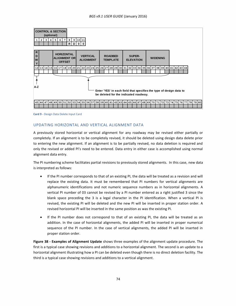
BGS v9.1 USER GUIDE (January 2016)
74
Card 9 - Design Data Delete Input Card
UPDATING HORIZONTAL AND VERTICAL ALIGNMENT DATA
A previously stored horizontal or vertical alignment for any roadway may be revised either partially or
completely. If an alignment is to be completely revised, it should be deleted using design data delete prior
to entering the new alignment. If an alignment is to be partially revised, no data deletion is required and
only the revised or added PI’s need to be entered. Data entry in either case is accomplished using normal
alignment data entry.
The PI numbering scheme facilitates partial revisions to previously stored alignments. In this case, new data
is interpreted as follows:
If the PI number corresponds to that of an existing PI, the data will be treated as a revision and will
replace the existing data. It must be remembered that PI numbers for vertical alignments are
alphanumeric identifications and not numeric sequence numbers as in horizontal alignments. A
vertical PI number of 03 cannot be revised by a PI number entered as a right justified 3 since the
blank space preceding the 3 is a legal character in the PI identification. When a vertical PI is
revised, the existing PI will be deleted and the new PI will be inserted in proper station order. A
revised horizontal PI will be inserted in the same position as was the existing PI.
If the PI number does not correspond to that of an existing PI, the data will be treated as an
addition. In the case of horizontal alignments, the added PI will be inserted in proper numerical
sequence of the PI number. In the case of vertical alignments, the added PI will be inserted in
proper station order.
Figure 38 - Examples of Alignment Update shows three examples of the alignment update procedure. The
first is a typical case showing revisions and additions to a horizontal alignment. The second is an update to a
horizontal alignment illustrating how a PI can be deleted even though there is no direct deletion facility. The
third is a typical case showing revisions and additions to a vertical alignment.
1 2 3 4 5 6 7 8 9 10 11
R D 0 0
12 13 14 15 16 17 18 19 20 21 22 23 24 25 26 27 28 29 30 31 32 33 34 35 36 37 38 39 40 41 42 43 44
A-Z
45 46 47 48 49 50 51 52 53 54 55 56 57 58 59 60 61 62 63 64 65 66 67 68 69 70 71 72 73 74 75 76 77 78 79 80
Enter 'YES' in each field that specifies the type of design data to
be deleted for the indicated roadway.
CONTROL & SECTION
(optional)
R
D
W
Y
HORIZONTAL
ALIGNMENT OR
OFFSET
VERTICAL
ALIGNMENT
ROADBED
TEMPLATE
SUPER-
ELEVATIONWIDENING
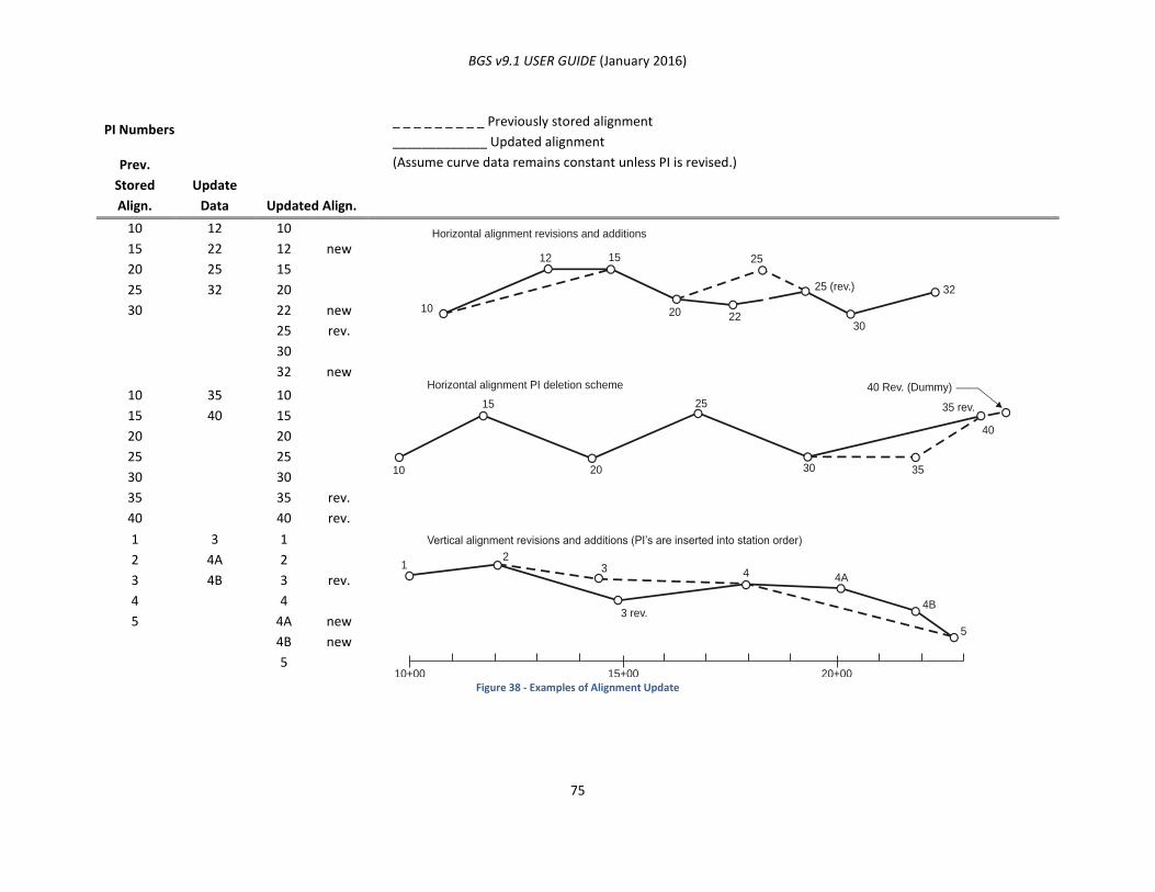
BGS v9.1 USER GUIDE (January 2016)
75
Figure 38 - Examples of Alignment Update
PI Numbers _ _ _ _ _ _ _ _ _ Previously stored alignment
_____________ Updated alignment
(Assume curve data remains constant unless PI is revised.) Prev.
Stored
Align.
Update
Data Updated Align.
10
15
20
25
30
12
22
25
32
10
12
15
20
22
25
30
32
new
new
rev.
new
10
15
20
25
30
35
40
35
40
10
15
20
25
30
35
40
rev.
rev.
1
2
3
4
5
3
4A
4B
1
2
3
4
4A
4B
5
rev.
new
new
Horizontal alignment revisions and additions
Horizontal alignment PI deletion scheme
Vertical alignment revisions and additions (PI’s are inserted into station order)
10
10
1
10+00 15+00 20+00
23
3 rev.
4 4A
4B
5
12 15
15
20
20
2230
30 35
40
35 rev.
40 Rev. (Dummy)
25
25
25 (rev.) 32
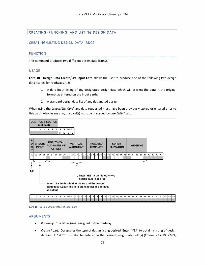
BGS v9.1 USER GUIDE (January 2016)
76
CREATING (PUNCHING) AND LISTING DESIGN DATA
CREATING/LISTING DESIGN DATA (RD02)
FUNCTION
This command produces two different design data listings.
USAGE
Card 10 - Design Data Create/List Input Card allows the user to produce one of the following two design
data listings for roadways A-Z:
1. A data input listing of any designated design data which will present the data in the original
format as entered on the input cards.
2. A standard design data list of any designated design.
When using the Create/List Card, any data requested must have been previously stored or entered prior to
this card. Also, in any run, the card(s) must be preceded by one CMNT card.
Card 10 - Design Data Create/List Input Card
ARGUMENTS
Roadway: The letter (A–Z) assigned to the roadway.
Create Input: Designates the type of design listing desired. Enter “YES” to obtain a listing of design
data input. “YES” must also be entered in the desired design data field(s) (Columns 17-19, 22-24,
1 2 3 4 5 6 7 8 9 10 11
R D 0 2
12 13 14 15 16 17 18 19 20 21 22 23 24 25 26 27 28 29 30 31 32 33 34 35 36 37 38 39 40 41 42 43 44
A-Z
1 2 3 4 5 6 7 8 9 10 11 12 13 14 15 16 17 18 19 20 21 22 23 24 25 26 27 28 29 30 31 32 33 34 35 36
WIDENING
Enter 'YES' in the fields where
design data is desired.
R
D
W
Y
CONTROL & SECTION
(optional)
CREATE
INPUT
HORIZONTAL
ALIGNMENT OF
OFFSET
VERTICAL
ALIGNMENT
ROADBED
TEMPLATE
SUPER-
ELEVATION
Enter 'YES' in this field to create and list design
input data. Leave this field blank to list design data
as output.
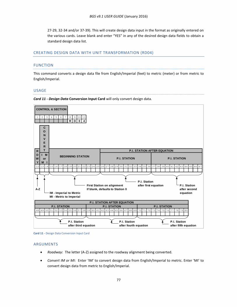
BGS v9.1 USER GUIDE (January 2016)
77
27-29, 32-34 and/or 37-39). This will create design data input in the format as originally entered on
the various cards. Leave blank and enter “YES” in any of the desired design data fields to obtain a
standard design data list.
CREATING DESIGN DATA WITH UNIT TRANSFORMATION (RD04)
FUNCTION
This command converts a design data file from English/Imperial (feet) to metric (meter) or from metric to
English/Imperial.
USAGE
Card 11 - Design Data Conversion Input Card will only convert design data.
Card 11 - Design Data Conversion Input Card
ARGUMENTS
Roadway: The letter (A-Z) assigned to the roadway alignment being converted.
Convert IM or MI: Enter ‘IM’ to convert design data from English/Imperial to metric. Enter ‘MI’ to
convert design data from metric to English/Imperial.
1 2 3 4 5 6 7 8 9 10 11
R D 0 4
12 13 14 15 16 17 18 19 20 21 22 23 24 25 26 27 28 29 30 31 32 33 34 35 36 37 38 39 40 41 42 43 44 45 46 47
P.I. Station
First Station on alignment after first equation P.I. Station
A-Z If blank, defaults to Station 0 after second
IM - Imperial to Metric equation
MI - Metric to Imperial
48 49 50 51 52 53 54 55 56 57 58 59 60 61 62 63 64 65 66 67 68 69 70 71 72 73 74 75 76 77 78 79 80
P.I. Station P.I. Station P.I. Station
after third equation after fourth equation after fifth equation
CONTROL & SECTION
P.I. STATION AFTER EQUATION
P.I. STATION P.I. STATION P.I. STATION
R
D
W
Y
P.I. STATION
P.I. STATION AFTER EQUATION
C
O
N
V
E
R
T
P.I. STATION
I M
or
M I
BEGINNING STATION

BGS v9.1 USER GUIDE (January 2016)
78
Beginning Station: Assigns the station to be the beginning station on the converted horizontal
alignment. The user MUST soft-convert the original beginning station to the units of measurement
required and enter the value in this field. If left blank, the stationing will begin at 0.
P.I. Station After Equation: There are five (5) P.I. Station after Equation Fields. Entries are made in
the order of the equations on the alignment. Use these fields only if there is an equation for the
alignment that is indicated in Column 12. Enter the P.I. station following the first equation in
columns 26-36, the P.I. station following the second equation in columns 37-47, the P.I. station
following the third equation in columns 48-58, the P.I. station following the fourth equation in
columns 59-69 and the P.I. station following the fifth equation in columns 70-8.
Table 7 - Maximum Amount of Design Data Permitted
* As many entries as desired may be referenced from any roadway (A-G) as long as the total number of
entries does not exceed the maximum per project.
** Tabular data is available to all roadways.
NA – Not applicable
DESIGN DATA TYPE
ALIGNMENTS A-G ALIGNMENTS H-Z STORE / RECALL
AND OTHER
TABULAR DATA
PER
ROADWAY
PER
PROJECT PER ROADWAY
Horizontal Alignment
Profile Grade
Template
Superelevation
Widening
RD05
RD10
RD30
RD20
RD25
100 PI’s
*
*
*
*
NA
250 PI’s
500 entries
500 entries
250 entries
25 PI’s
25 PI’s
15 entries
50 entries
10 entries
NA
NA
70 descriptions**
NA
NA
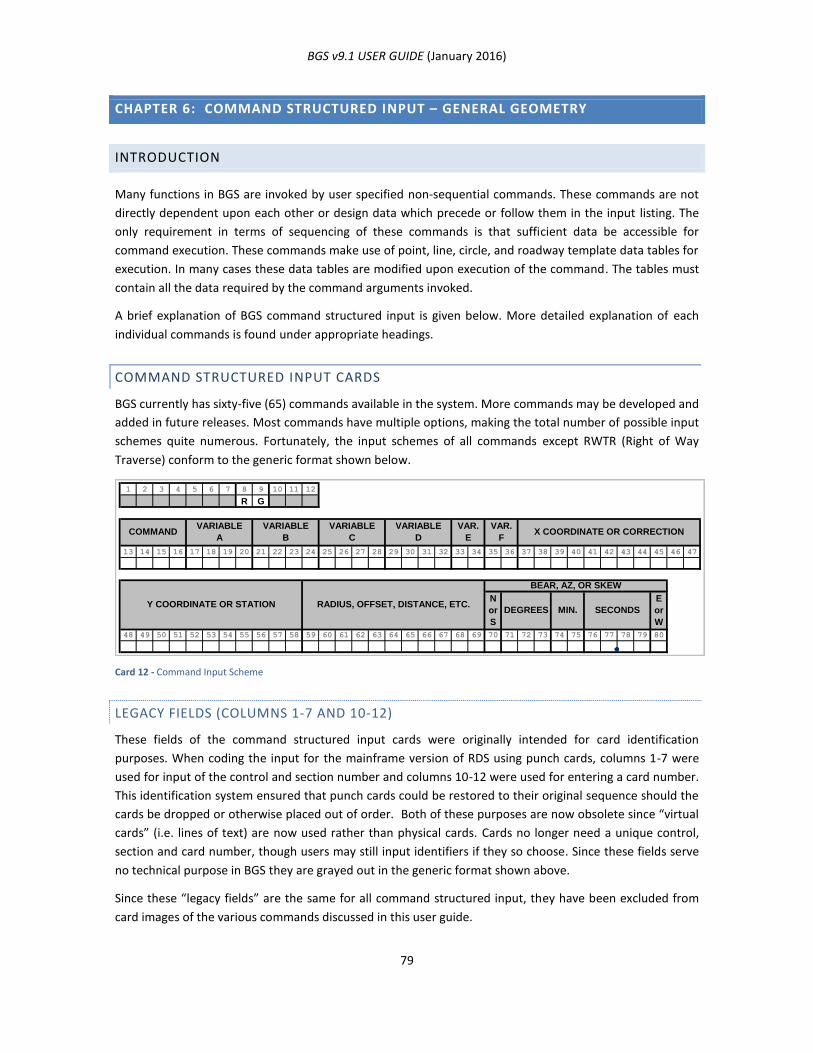
BGS v9.1 USER GUIDE (January 2016)
79
CHAPTER 6: COMMAND STRUCTURED INPUT – GENERAL GEOMETRY
INTRODUCTION
Many functions in BGS are invoked by user specified non-sequential commands. These commands are not
directly dependent upon each other or design data which precede or follow them in the input listing. The
only requirement in terms of sequencing of these commands is that sufficient data be accessible for
command execution. These commands make use of point, line, circle, and roadway template data tables for
execution. In many cases these data tables are modified upon execution of the command. The tables must
contain all the data required by the command arguments invoked.
A brief explanation of BGS command structured input is given below. More detailed explanation of each
individual commands is found under appropriate headings.
COMMAND STRUCTURED INPUT CARDS
BGS currently has sixty-five (65) commands available in the system. More commands may be developed and
added in future releases. Most commands have multiple options, making the total number of possible input
schemes quite numerous. Fortunately, the input schemes of all commands except RWTR (Right of Way
Traverse) conform to the generic format shown below.
Card 12 - Command Input Scheme
LEGACY FIELDS (COLUMNS 1-7 AND 10-12)
These fields of the command structured input cards were originally intended for card identification
purposes. When coding the input for the mainframe version of RDS using punch cards, columns 1-7 were
used for input of the control and section number and columns 10-12 were used for entering a card number.
This identification system ensured that punch cards could be restored to their original sequence should the
cards be dropped or otherwise placed out of order. Both of these purposes are now obsolete since “virtual
cards” (i.e. lines of text) are now used rather than physical cards. Cards no longer need a unique control,
section and card number, though users may still input identifiers if they so choose. Since these fields serve
no technical purpose in BGS they are grayed out in the generic format shown above.
Since these “legacy fields” are the same for all command structured input, they have been excluded from
card images of the various commands discussed in this user guide.
1 2 3 4 5 6 7 8 9 10 11 12
R G
13 14 15 16 17 18 19 20 21 22 23 24 25 26 27 28 29 30 31 32 33 34 35 36 37 38 39 40 41 42 43 44 45 46 47
N
or
S
E
or
W
48 49 50 51 52 53 54 55 56 57 58 59 60 61 62 63 64 65 66 67 68 69 70 71 72 73 74 75 76 77 78 79 80
Y COORDINATE OR STATION RADIUS, OFFSET, DISTANCE, ETC.
BEAR, AZ, OR SKEW
DEGREES MIN. SECONDS
VARIABLE
D
VAR.
E
VAR.
FX COORDINATE OR CORRECTIONCOMMAND
VARIABLE
A
VARIABLE
B
VARIABLE
C
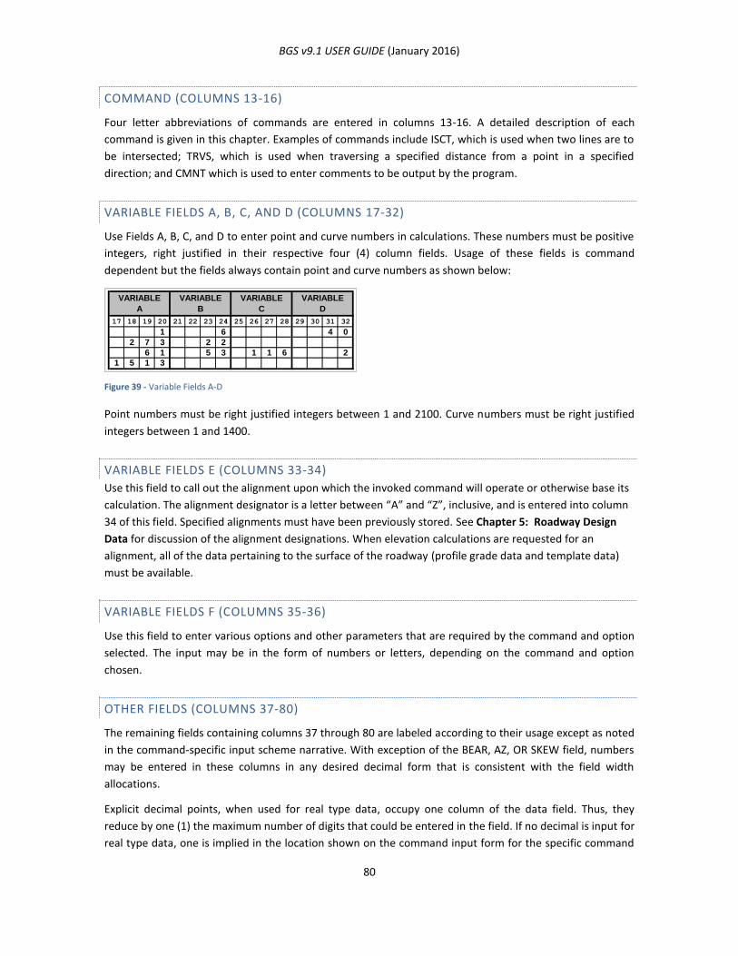
BGS v9.1 USER GUIDE (January 2016)
80
COMMAND (COLUMNS 13-16)
Four letter abbreviations of commands are entered in columns 13-16. A detailed description of each
command is given in this chapter. Examples of commands include ISCT, which is used when two lines are to
be intersected; TRVS, which is used when traversing a specified distance from a point in a specified
direction; and CMNT which is used to enter comments to be output by the program.
VARIABLE FIELDS A, B, C, AND D (COLUMNS 17-32)
Use Fields A, B, C, and D to enter point and curve numbers in calculations. These numbers must be positive
integers, right justified in their respective four (4) column fields. Usage of these fields is command
dependent but the fields always contain point and curve numbers as shown below:
Figure 39 - Variable Fields A-D
Point numbers must be right justified integers between 1 and 2100. Curve numbers must be right justified
integers between 1 and 1400.
VARIABLE FIELDS E (COLUMNS 33-34)
Use this field to call out the alignment upon which the invoked command will operate or otherwise base its
calculation. The alignment designator is a letter between “A” and “Z”, inclusive, and is entered into column
34 of this field. Specified alignments must have been previously stored. See Chapter 5: Roadway Design
Data for discussion of the alignment designations. When elevation calculations are requested for an
alignment, all of the data pertaining to the surface of the roadway (profile grade data and template data)
must be available.
VARIABLE FIELDS F (COLUMNS 35-36)
Use this field to enter various options and other parameters that are required by the command and option
selected. The input may be in the form of numbers or letters, depending on the command and option
chosen.
OTHER FIELDS (COLUMNS 37-80)
The remaining fields containing columns 37 through 80 are labeled according to their usage except as noted
in the command-specific input scheme narrative. With exception of the BEAR, AZ, OR SKEW field, numbers
may be entered in these columns in any desired decimal form that is consistent with the field width
allocations.
Explicit decimal points, when used for real type data, occupy one column of the data field. Thus, they
reduce by one (1) the maximum number of digits that could be entered in the field. If no decimal is input for
real type data, one is implied in the location shown on the command input form for the specific command
VARIABLE
A
VARIABLE
B
VARIABLE
C
VARIABLE
D
17 18 19 20 21 22 23 24 25 26 27 28 29 30 31 32
1 6 4 0
2 7 3 2 2
6 1 5 3 1 1 6 2
1 5 1 3
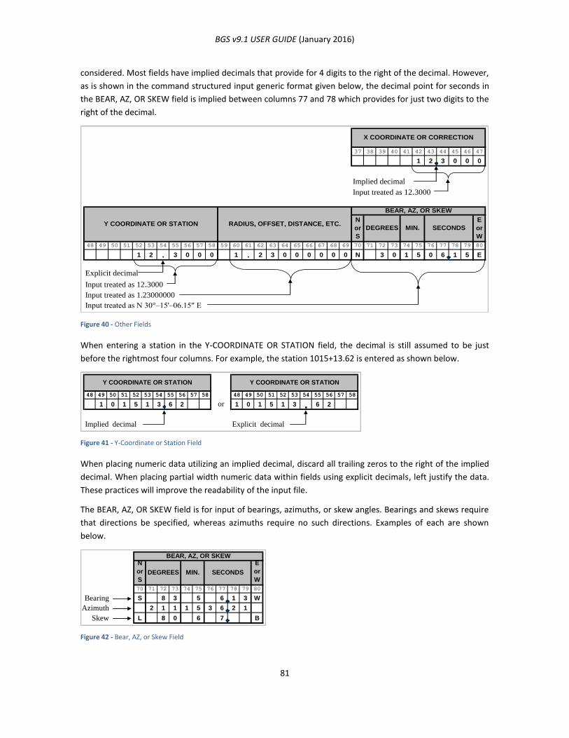
BGS v9.1 USER GUIDE (January 2016)
81
considered. Most fields have implied decimals that provide for 4 digits to the right of the decimal. However,
as is shown in the command structured input generic format given below, the decimal point for seconds in
the BEAR, AZ, OR SKEW field is implied between columns 77 and 78 which provides for just two digits to the
right of the decimal.
Figure 40 - Other Fields
When entering a station in the Y-COORDINATE OR STATION field, the decimal is still assumed to be just
before the rightmost four columns. For example, the station 1015+13.62 is entered as shown below.
Figure 41 - Y-Coordinate or Station Field
When placing numeric data utilizing an implied decimal, discard all trailing zeros to the right of the implied
decimal. When placing partial width numeric data within fields using explicit decimals, left justify the data.
These practices will improve the readability of the input file.
The BEAR, AZ, OR SKEW field is for input of bearings, azimuths, or skew angles. Bearings and skews require
that directions be specified, whereas azimuths require no such directions. Examples of each are shown
below.
Figure 42 - Bear, AZ, or Skew Field
37 38 39 40 41 42 43 44 45 46 47
1 2 3 0 0 0
Implied decimal
Input treated as 12.3000
N
or
S
E
or
W
48 49 50 51 52 53 54 55 56 57 58 59 60 61 62 63 64 65 66 67 68 69 70 71 72 73 74 75 76 77 78 79 80
1 2 . 3 0 0 0 1 . 2 3 0 0 0 0 0 0 N 3 0 1 5 0 6 1 5 E
Explicit decimal
Input treated as 12.3000
Input treated as 1.23000000
Input treated as N 30°–15'–06.15" E
X COORDINATE OR CORRECTION
Y COORDINATE OR STATION RADIUS, OFFSET, DISTANCE, ETC.
BEAR, AZ, OR SKEW
DEGREES MIN. SECONDS
48 49 50 51 52 53 54 55 56 57 58 48 49 50 51 52 53 54 55 56 57 58
1 0 1 5 1 3 6 2 or 1 0 1 5 1 3 . 6 2
Implied decimal Explicit decimal
Y COORDINATE OR STATION Y COORDINATE OR STATION
N
or
S
E
or
W
70 71 72 73 74 75 76 77 78 79 80
Bearing S 8 3 5 6 1 3 W
Azimuth 2 1 1 1 5 3 6 2 1
Skew L 8 0 6 7 B
DEGREES MIN. SECONDS
BEAR, AZ, OR SKEW

BGS v9.1 USER GUIDE (January 2016)
82
Bearings or azimuths may be used interchangeably when either is called for. Azimuths are expressed as
angles measured clockwise from the south (S) direction.
MODIFYING REPORT OUTPUT
The following three commands allow limited customization of BGS program output.
CMNT (COMMENT)
Use this command to instruct BGS to print specified characters (alphanumeric data) entered in columns 37
thru 80 in the program output. This command may be used to insert helpful comments in the output.
Characters allowed for input include upper and lower case letters, numbers, blank spaces, and the following
special characters: /, +, -, ., (, ), $, *, and =.
Card 13 - CMNT Argument Input Scheme Card
SKIP
Use this command to skip a specified number of lines in the output or, said differently, to insert a specified
number of blank lines in the output.
Card 14 - SKIP Argument Input Scheme Card
EJCT (EJECT)
Use this command to cause the subsequent output to begin at the top of a new page.
13 14 15 16 17 18 19 20 21 22 23 24 25 26 27 28 29 30 31 32 33 34 35 36 37 38 39 40 41 42 43 44 45 46 47
C M N T
These characters will be printed on the output
N
or
S
E
or
W
48 49 50 51 52 53 54 55 56 57 58 59 60 61 62 63 64 65 66 67 68 69 70 71 72 73 74 75 76 77 78 79 80
These characters will be printed on the output
Y COORDINATE OR STATION RADIUS, OFFSET, DISTANCE, ETC.
BEAR, AZ, OR SKEW
DEGREES MIN. SECONDS
VARIABLE
D
VAR.
E
VAR.
FX COORDINATE OR CORRECTIONCOMMAND
VARIABLE
A
VARIABLE
B
VARIABLE
C
13 14 15 16 17 18 19 20 21 22 23 24 25 26 27 28 29 30 31 32 33 34 35 36 37 38 39 40 41 42 43 44 45 46 47
S K I P
Number of lines to be skiped (If blank, one line will be skipped).
N
or
S
E
or
W
48 49 50 51 52 53 54 55 56 57 58 59 60 61 62 63 64 65 66 67 68 69 70 71 72 73 74 75 76 77 78 79 80
SECONDSY COORDINATE OR STATION RADIUS, OFFSET, DISTANCE, ETC. DEGREES MIN.
VARIABLE
D
VAR.
E
VAR.
FX COORDINATE OR CORRECTIONCOMMAND
VARIABLE
A
VARIABLE
B
VARIABLE
C
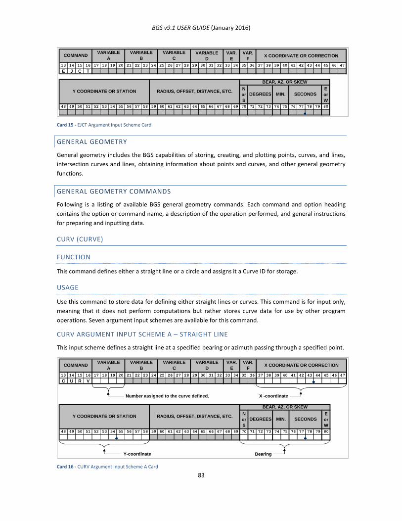
BGS v9.1 USER GUIDE (January 2016)
83
Card 15 - EJCT Argument Input Scheme Card
GENERAL GEOMETRY
General geometry includes the BGS capabilities of storing, creating, and plotting points, curves, and lines,
intersection curves and lines, obtaining information about points and curves, and other general geometry
functions.
GENERAL GEOMETRY COMMANDS
Following is a listing of available BGS general geometry commands. Each command and option heading
contains the option or command name, a description of the operation performed, and general instructions
for preparing and inputting data.
CURV (CURVE)
FUNCTION
This command defines either a straight line or a circle and assigns it a Curve ID for storage.
USAGE
Use this command to store data for defining either straight lines or curves. This command is for input only,
meaning that it does not perform computations but rather stores curve data for use by other program
operations. Seven argument input schemes are available for this command.
CURV ARGUMENT INPUT SCHEME A – STRAIGHT LINE
This input scheme defines a straight line at a specified bearing or azimuth passing through a specified point.
Card 16 - CURV Argument Input Scheme A Card
VARIABLE
D
VAR.
E
VAR.
FX COORDINATE OR CORRECTION
13 14 15 16 17 18 19 20 21 22 23 24 25 26 27 28 29 30 31 32 33 34 35 36 37 38 39 40 41 42 43 44 45 46 47
E J C T
N
or
S
E
or
W
48 49 50 51 52 53 54 55 56 57 58 59 60 61 62 63 64 65 66 67 68 69 70 71 72 73 74 75 76 77 78 79 80
VARIABLE
C
RADIUS, OFFSET, DISTANCE, ETC.
BEAR, AZ, OR SKEW
DEGREES MIN. SECONDSY COORDINATE OR STATION
COMMANDVARIABLE
A
VARIABLE
B
13 14 15 16 17 18 19 20 21 22 23 24 25 26 27 28 29 30 31 32 33 34 35 36 37 38 39 40 41 42 43 44 45 46 47
C U R V
Number assigned to the curve defined. X -coordinate
N
or
S
E
or
W
48 49 50 51 52 53 54 55 56 57 58 59 60 61 62 63 64 65 66 67 68 69 70 71 72 73 74 75 76 77 78 79 80
Y-coordinate Bearing
COMMANDVARIABLE
A
VARIABLE
B
VARIABLE
C
VARIABLE
D
VAR.
E
VAR.
FX COORDINATE OR CORRECTION
Y COORDINATE OR STATION RADIUS, OFFSET, DISTANCE, ETC.
BEAR, AZ, OR SKEW
DEGREES MIN. SECONDS
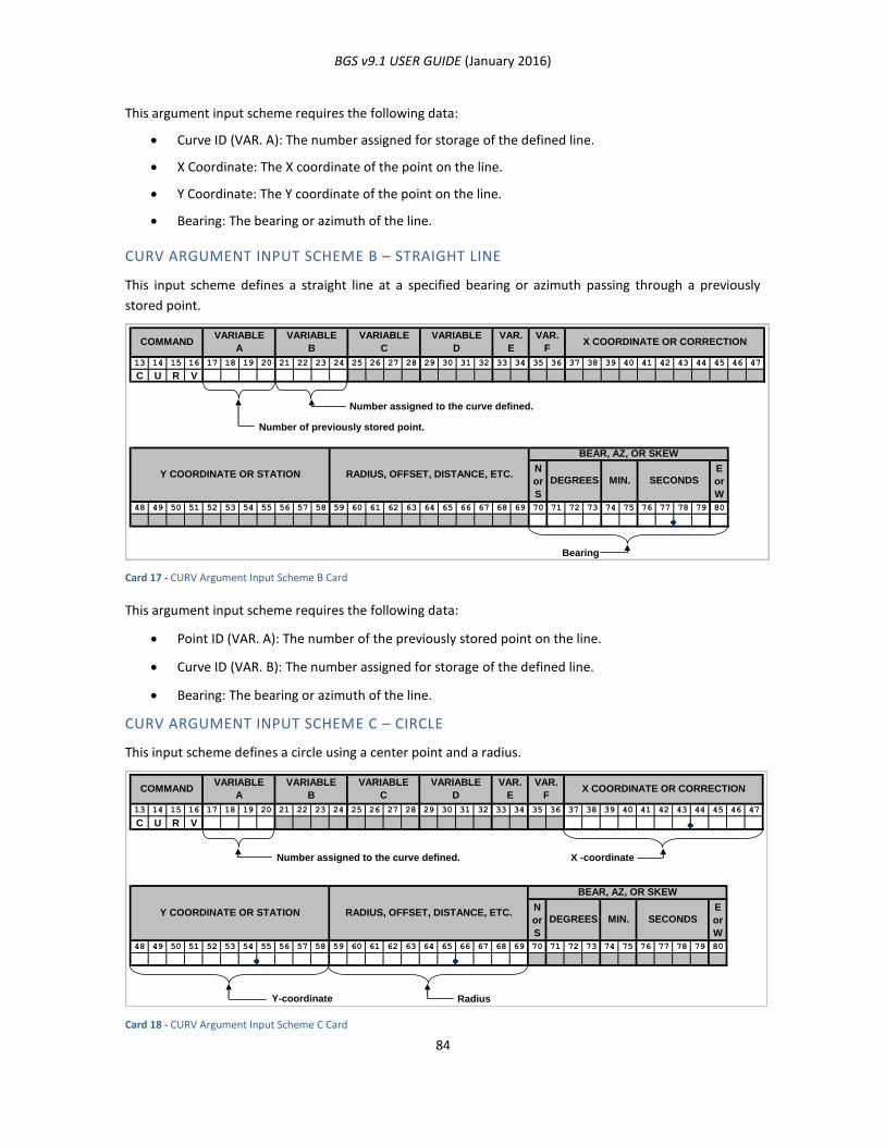
BGS v9.1 USER GUIDE (January 2016)
84
This argument input scheme requires the following data:
Curve ID (VAR. A): The number assigned for storage of the defined line.
X Coordinate: The X coordinate of the point on the line.
Y Coordinate: The Y coordinate of the point on the line.
Bearing: The bearing or azimuth of the line.
CURV ARGUMENT INPUT SCHEME B – STRAIGHT LINE
This input scheme defines a straight line at a specified bearing or azimuth passing through a previously
stored point.
Card 17 - CURV Argument Input Scheme B Card
This argument input scheme requires the following data:
Point ID (VAR. A): The number of the previously stored point on the line.
Curve ID (VAR. B): The number assigned for storage of the defined line.
Bearing: The bearing or azimuth of the line.
CURV ARGUMENT INPUT SCHEME C – CIRCLE
This input scheme defines a circle using a center point and a radius.
Card 18 - CURV Argument Input Scheme C Card
13 14 15 16 17 18 19 20 21 22 23 24 25 26 27 28 29 30 31 32 33 34 35 36 37 38 39 40 41 42 43 44 45 46 47
C U R V
Number assigned to the curve defined.
Number of previously stored point.
N
or
S
E
or
W
48 49 50 51 52 53 54 55 56 57 58 59 60 61 62 63 64 65 66 67 68 69 70 71 72 73 74 75 76 77 78 79 80
Bearing
COMMANDVARIABLE
A
VARIABLE
B
VARIABLE
C
VARIABLE
D
VAR.
E
VAR.
FX COORDINATE OR CORRECTION
Y COORDINATE OR STATION RADIUS, OFFSET, DISTANCE, ETC.
BEAR, AZ, OR SKEW
DEGREES MIN. SECONDS
13 14 15 16 17 18 19 20 21 22 23 24 25 26 27 28 29 30 31 32 33 34 35 36 37 38 39 40 41 42 43 44 45 46 47
C U R V
Number assigned to the curve defined. X -coordinate
N
or
S
E
or
W
48 49 50 51 52 53 54 55 56 57 58 59 60 61 62 63 64 65 66 67 68 69 70 71 72 73 74 75 76 77 78 79 80
Y-coordinate Radius
COMMANDVARIABLE
A
VARIABLE
B
VARIABLE
C
VARIABLE
D
VAR.
E
VAR.
FX COORDINATE OR CORRECTION
SECONDS
BEAR, AZ, OR SKEW
Y COORDINATE OR STATION RADIUS, OFFSET, DISTANCE, ETC.DEGREES MIN.
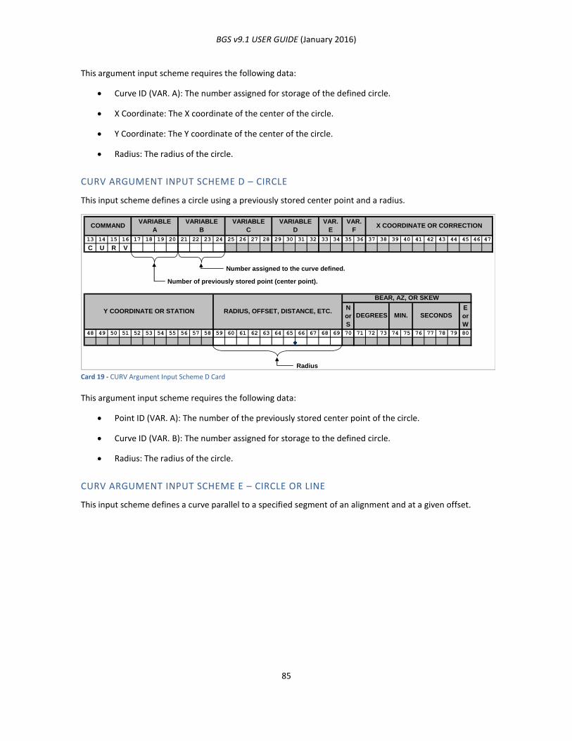
BGS v9.1 USER GUIDE (January 2016)
85
This argument input scheme requires the following data:
Curve ID (VAR. A): The number assigned for storage of the defined circle.
X Coordinate: The X coordinate of the center of the circle.
Y Coordinate: The Y coordinate of the center of the circle.
Radius: The radius of the circle.
CURV ARGUMENT INPUT SCHEME D – CIRCLE
This input scheme defines a circle using a previously stored center point and a radius.
Card 19 - CURV Argument Input Scheme D Card
This argument input scheme requires the following data:
Point ID (VAR. A): The number of the previously stored center point of the circle.
Curve ID (VAR. B): The number assigned for storage to the defined circle.
Radius: The radius of the circle.
CURV ARGUMENT INPUT SCHEME E – CIRCLE OR LINE
This input scheme defines a curve parallel to a specified segment of an alignment and at a given offset.
13 14 15 16 17 18 19 20 21 22 23 24 25 26 27 28 29 30 31 32 33 34 35 36 37 38 39 40 41 42 43 44 45 46 47
C U R V
Number assigned to the curve defined.
Number of previously stored point (center point).
N
or
S
E
or
W
48 49 50 51 52 53 54 55 56 57 58 59 60 61 62 63 64 65 66 67 68 69 70 71 72 73 74 75 76 77 78 79 80
Radius
COMMANDVARIABLE
A
VARIABLE
B
VARIABLE
C
VARIABLE
D
VAR.
E
VAR.
FX COORDINATE OR CORRECTION
SECONDS
BEAR, AZ, OR SKEW
Y COORDINATE OR STATION RADIUS, OFFSET, DISTANCE, ETC.DEGREES MIN.
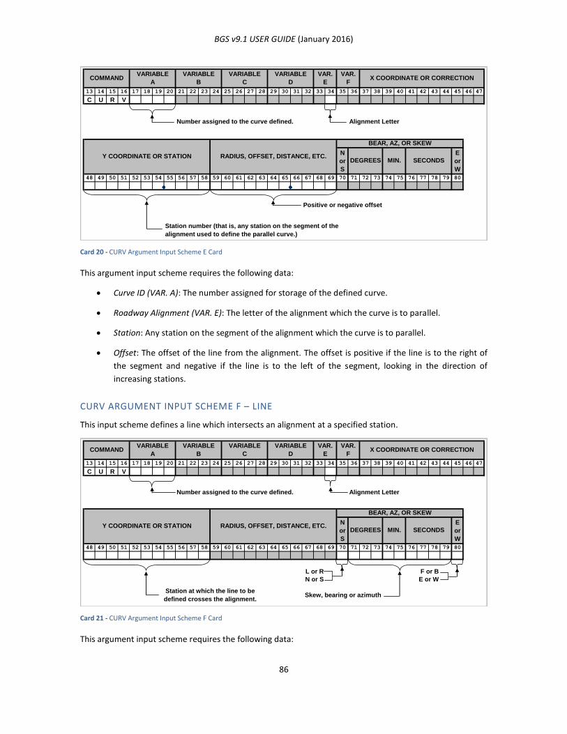
BGS v9.1 USER GUIDE (January 2016)
86
Card 20 - CURV Argument Input Scheme E Card
This argument input scheme requires the following data:
Curve ID (VAR. A): The number assigned for storage of the defined curve.
Roadway Alignment (VAR. E): The letter of the alignment which the curve is to parallel.
Station: Any station on the segment of the alignment which the curve is to parallel.
Offset: The offset of the line from the alignment. The offset is positive if the line is to the right of
the segment and negative if the line is to the left of the segment, looking in the direction of
increasing stations.
CURV ARGUMENT INPUT SCHEME F – LINE
This input scheme defines a line which intersects an alignment at a specified station.
Card 21 - CURV Argument Input Scheme F Card
This argument input scheme requires the following data:
13 14 15 16 17 18 19 20 21 22 23 24 25 26 27 28 29 30 31 32 33 34 35 36 37 38 39 40 41 42 43 44 45 46 47
C U R V
Number assigned to the curve defined. Alignment Letter
N
or
S
E
or
W
48 49 50 51 52 53 54 55 56 57 58 59 60 61 62 63 64 65 66 67 68 69 70 71 72 73 74 75 76 77 78 79 80
Positive or negative offset
Station number (that is, any station on the segment of the
alignment used to define the parallel curve.)
Y COORDINATE OR STATION RADIUS, OFFSET, DISTANCE, ETC.
BEAR, AZ, OR SKEW
DEGREES MIN. SECONDS
VARIABLE
D
VAR.
E
VAR.
FX COORDINATE OR CORRECTIONCOMMAND
VARIABLE
A
VARIABLE
B
VARIABLE
C
13 14 15 16 17 18 19 20 21 22 23 24 25 26 27 28 29 30 31 32 33 34 35 36 37 38 39 40 41 42 43 44 45 46 47
C U R V
Number assigned to the curve defined. Alignment Letter
N
or
S
E
or
W
48 49 50 51 52 53 54 55 56 57 58 59 60 61 62 63 64 65 66 67 68 69 70 71 72 73 74 75 76 77 78 79 80
L or R F or B
N or S E or W
Station at which the line to be
defined crosses the alignment.Skew, bearing or azimuth
SECONDS
BEAR, AZ, OR SKEW
Y COORDINATE OR STATION RADIUS, OFFSET, DISTANCE, ETC.DEGREES MIN.
VARIABLE
D
VAR.
E
VAR.
FX COORDINATE OR CORRECTIONCOMMAND
VARIABLE
A
VARIABLE
B
VARIABLE
C

BGS v9.1 USER GUIDE (January 2016)
87
Curve ID (VAR. A): The number assigned for storage of the defined line.
Roadway Alignment (VAR. E): The letter of the alignment the line is to intersect.
Station: The station on the alignment at the point where the line is to intersect the alignment.
Bearing: The bearing, azimuth or skew of the line at the point of intersection. See the Note and
diagram below.
NOTES ON CURV COMMAND
If the skew option is used, the skew must be given in the columns headed BEAR, AZ, or SKEW in one of the
four following forms:
1. R, DEG, MIN, SEC, F = right forward skew.
2. L, DEG, MIN, SEC, F = left forward skew.
3. R, DEG, MIN, SEC, B = right backward skew.
4. L, DEG, MIN, SEC, B = left backward skew.
All skew angles are measured from a line perpendicular to the station line at the given station. Forward
indicates that the skew is to be measured in the direction of increasing stations; backward indicates
decreasing stations. Right and left is determined by looking in the direction of increasing stations.
Since the new line must be stored with a direction, it is necessary to designate whether it extends to the left
(L) or right (R) from the station line and whether it is forward (F) or backward (B) from the perpendicular or
radial line as shown in the sketch below.
Figure 43 - Skew Angles
CURV ARGUMENT INPUT SCHEME G – CIRCLE
This input scheme defines a circle using a previously stored center point and a previously stored point on
the circumference.
Station Line
= Skew Angle
L B
R F
F
R B
L
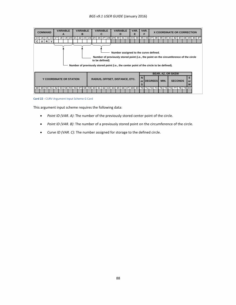
BGS v9.1 USER GUIDE (January 2016)
88
Card 22 - CURV Argument Input Scheme G Card
This argument input scheme requires the following data:
Point ID (VAR. A): The number of the previously stored center point of the circle.
Point ID (VAR. B): The number of a previously stored point on the circumference of the circle.
Curve ID (VAR. C): The number assigned for storage to the defined circle.
13 14 15 16 17 18 19 20 21 22 23 24 25 26 27 28 29 30 31 32 33 34 35 36 37 38 39 40 41 42 43 44 45 46 47
C U R V
Number assigned to the curve defined.
Number of previously stored point (i.e., the center point of the circle to be defined).
N
or
S
E
or
W
48 49 50 51 52 53 54 55 56 57 58 59 60 61 62 63 64 65 66 67 68 69 70 71 72 73 74 75 76 77 78 79 80
Y COORDINATE OR STATION RADIUS, OFFSET, DISTANCE, ETC.
BEAR, AZ, OR SKEW
DEGREES MIN. SECONDS
Number of previously stored point (i.e., the point on the circumference of the circle
to be defined)
COMMANDVARIABLE
A
VARIABLE
B
VARIABLE
C
VARIABLE
D
VAR.
E
VAR.
FX COORDINATE OR CORRECTION

BGS v9.1 USER GUIDE (January 2016)
89
PONT (POINT)
FUNCTION
This command defines a point and stores it for later reference.
USAGE
Use this command to store the X and Y coordinates of a point of interest. PONT is used primarily for input
but can also be used for querying the system for calculated point-related information.
PONT ARGUMENT INPUT SCHEME A
This input scheme defines the point using X and Y coordinates.
Card 23 - PONT Argument Input Scheme A Card
This argument input scheme requires the following data:
Point ID (VAR. A): The number assigned for storage of the point.
Roadway Alignment (VAR. E): If provided, the system computes the station and offset of the point
from the given alignment measured along the line through the point perpendicular to the
alignment.
X Coordinate: The X coordinate of the point to be stored.
Y Coordinate: The Y coordinate of the point to be stored.
13 14 15 16 17 18 19 20 21 22 23 24 25 26 27 28 29 30 31 32 33 34 35 36 37 38 39 40 41 42 43 44 45 46 47
P O N T
Number assigned to
the point stored
Alignment
Letter
(optional)
X-coordinate
N
or
S
E
or
W
48 49 50 51 52 53 54 55 56 57 58 59 60 61 62 63 64 65 66 67 68 69 70 71 72 73 74 75 76 77 78 79 80
Y-coordinate
RADIUS, OFFSET, DISTANCE, ETC.
COMMANDVARIABLE
A
VARIABLE
B
VARIABLE
C
VARIABLE
D
VAR.
E
Y COORDINATE OR STATION
VAR.
FX COORDINATE OR CORRECTION
DEGREES
BEAR, AZ, OR SKEW
MIN. SECONDS
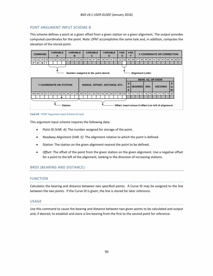
BGS v9.1 USER GUIDE (January 2016)
90
PONT ARGUMENT INPUT SCHEME B
This scheme defines a point at a given offset from a given station on a given alignment. The output provides
computed coordinates for the point. Note: ZPNT accomplishes the same task and, in addition, computes the
elevation of the stored point.
Card 24 - PONT Argument Input Scheme B Card
This argument input scheme requires the following data:
Point ID (VAR. A): The number assigned for storage of the point.
Roadway Alignment (VAR. E): The alignment relative to which the point is defined.
Station: The station on the given alignment nearest the point to be defined.
Offset: The offset of the point from the given station on the given alignment. Use a negative offset
for a point to the left of the alignment, looking in the direction of increasing stations.
BRDS (BEARING AND DISTANCE)
FUNCTION
Calculates the bearing and distance between two specified points. A Curve ID may be assigned to the line
between the two points. If the Curve ID is given, the line is stored for later reference.
USAGE
Use this command to cause the bearing and distance between two given points to be calculated and output
and, if desired, to establish and store a line bearing from the first to the second point for reference.
13 14 15 16 17 18 19 20 21 22 23 24 25 26 27 28 29 30 31 32 33 34 35 36 37 38 39 40 41 42 43 44 45 46 47
P O N T
Number assigned to the point stored Alignment Letter
N
or
S
E
or
W
48 49 50 51 52 53 54 55 56 57 58 59 60 61 62 63 64 65 66 67 68 69 70 71 72 73 74 75 76 77 78 79 80
Station Offset: Insert minus if offset is to left of alignment
VAR.
FX COORDINATE OR CORRECTIONCOMMAND
VARIABLE
A
VARIABLE
B
VARIABLE
C
VARIABLE
D
VAR.
E
Y COORDINATE OR STATION RADIUS, OFFSET, DISTANCE, ETC.DEGREES MIN. SECONDS
BEAR, AZ, OR SKEW
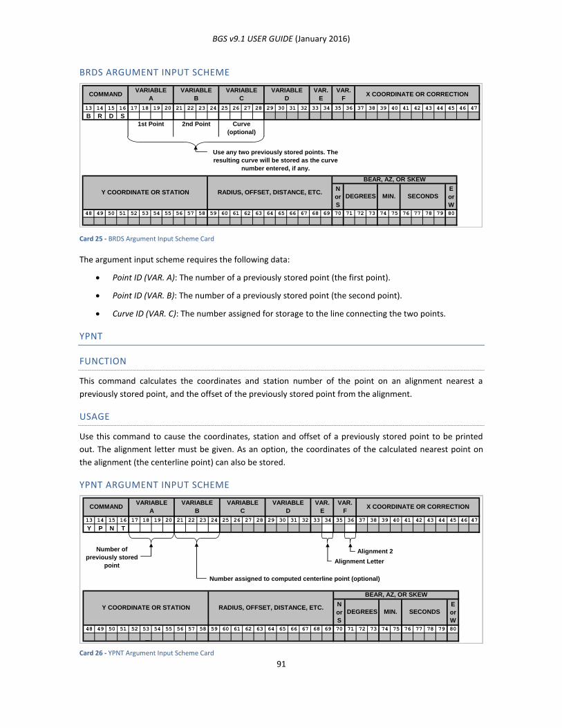
BGS v9.1 USER GUIDE (January 2016)
91
BRDS ARGUMENT INPUT SCHEME
Card 25 - BRDS Argument Input Scheme Card
The argument input scheme requires the following data:
Point ID (VAR. A): The number of a previously stored point (the first point).
Point ID (VAR. B): The number of a previously stored point (the second point).
Curve ID (VAR. C): The number assigned for storage to the line connecting the two points.
YPNT
FUNCTION
This command calculates the coordinates and station number of the point on an alignment nearest a
previously stored point, and the offset of the previously stored point from the alignment.
USAGE
Use this command to cause the coordinates, station and offset of a previously stored point to be printed
out. The alignment letter must be given. As an option, the coordinates of the calculated nearest point on
the alignment (the centerline point) can also be stored.
YPNT ARGUMENT INPUT SCHEME
Card 26 - YPNT Argument Input Scheme Card
13 14 15 16 17 18 19 20 21 22 23 24 25 26 27 28 29 30 31 32 33 34 35 36 37 38 39 40 41 42 43 44 45 46 47
B R D S
1st Point 2nd Point Curve
(optional)
Use any two previously stored points. The
resulting curve will be stored as the curve
number entered, if any.
N
or
S
E
or
W
48 49 50 51 52 53 54 55 56 57 58 59 60 61 62 63 64 65 66 67 68 69 70 71 72 73 74 75 76 77 78 79 80
VARIABLE
ACOMMAND
VAR.
E
VARIABLE
D
VARIABLE
C
VARIABLE
B
SECONDS
BEAR, AZ, OR SKEW
X COORDINATE OR CORRECTIONVAR.
F
Y COORDINATE OR STATION RADIUS, OFFSET, DISTANCE, ETC.DEGREES MIN.
13 14 15 16 17 18 19 20 21 22 23 24 25 26 27 28 29 30 31 32 33 34 35 36 37 38 39 40 41 42 43 44 45 46 47
Y P N T
Alignment 2
Alignment Letter
Number assigned to computed centerline point (optional)
N
or
S
E
or
W
48 49 50 51 52 53 54 55 56 57 58 59 60 61 62 63 64 65 66 67 68 69 70 71 72 73 74 75 76 77 78 79 80
Number of
previously stored
point
Y COORDINATE OR STATION RADIUS, OFFSET, DISTANCE, ETC.DEGREES MIN. SECONDS
BEAR, AZ, OR SKEW
X COORDINATE OR CORRECTIONVAR.
F
VARIABLE
ACOMMAND
VAR.
E
VARIABLE
D
VARIABLE
C
VARIABLE
B
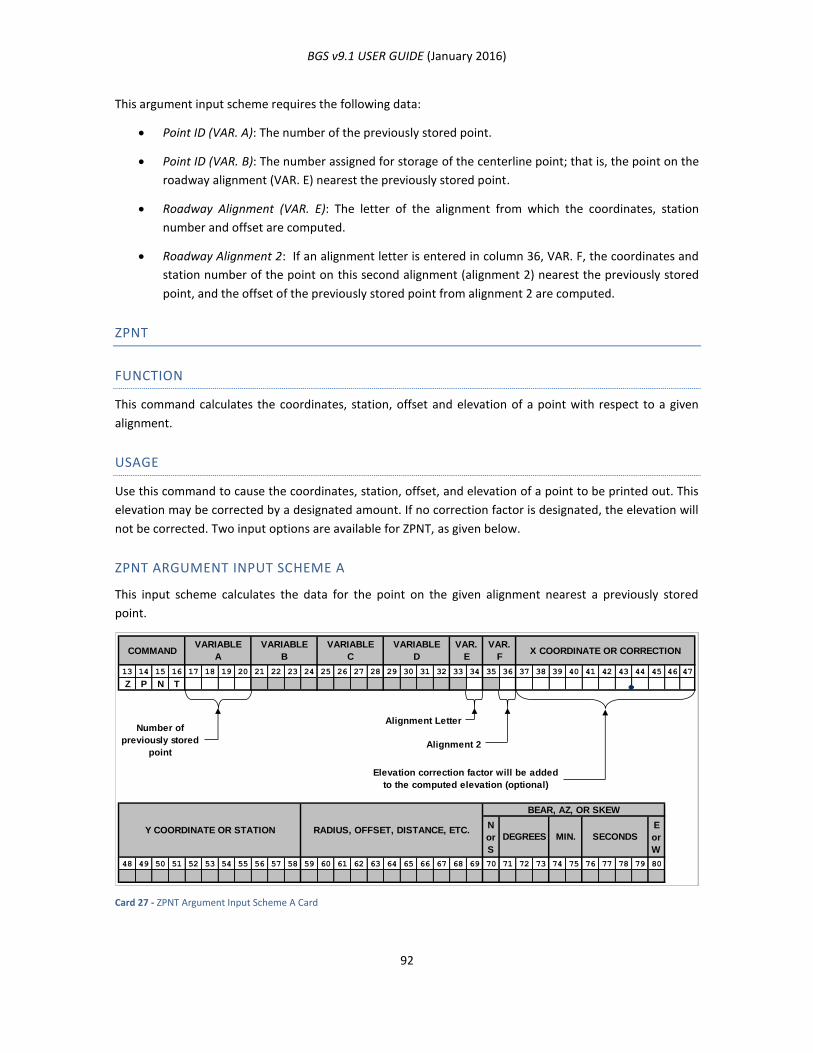
BGS v9.1 USER GUIDE (January 2016)
92
This argument input scheme requires the following data:
Point ID (VAR. A): The number of the previously stored point.
Point ID (VAR. B): The number assigned for storage of the centerline point; that is, the point on the
roadway alignment (VAR. E) nearest the previously stored point.
Roadway Alignment (VAR. E): The letter of the alignment from which the coordinates, station
number and offset are computed.
Roadway Alignment 2: If an alignment letter is entered in column 36, VAR. F, the coordinates and
station number of the point on this second alignment (alignment 2) nearest the previously stored
point, and the offset of the previously stored point from alignment 2 are computed.
ZPNT
FUNCTION
This command calculates the coordinates, station, offset and elevation of a point with respect to a given
alignment.
USAGE
Use this command to cause the coordinates, station, offset, and elevation of a point to be printed out. This
elevation may be corrected by a designated amount. If no correction factor is designated, the elevation will
not be corrected. Two input options are available for ZPNT, as given below.
ZPNT ARGUMENT INPUT SCHEME A
This input scheme calculates the data for the point on the given alignment nearest a previously stored
point.
Card 27 - ZPNT Argument Input Scheme A Card
13 14 15 16 17 18 19 20 21 22 23 24 25 26 27 28 29 30 31 32 33 34 35 36 37 38 39 40 41 42 43 44 45 46 47
Z P N T
Alignment Letter
Alignment 2
Elevation correction factor will be added
to the computed elevation (optional)
N
or
S
E
or
W
48 49 50 51 52 53 54 55 56 57 58 59 60 61 62 63 64 65 66 67 68 69 70 71 72 73 74 75 76 77 78 79 80
X COORDINATE OR CORRECTIONVAR.
F
VARIABLE
ACOMMAND
VAR.
E
VARIABLE
D
VARIABLE
C
VARIABLE
B
Number of
previously stored
point
Y COORDINATE OR STATION RADIUS, OFFSET, DISTANCE, ETC.DEGREES MIN. SECONDS
BEAR, AZ, OR SKEW
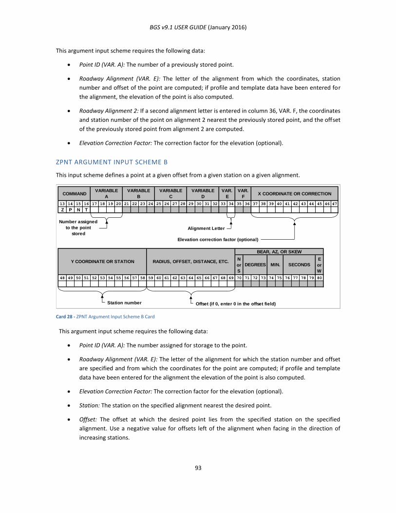
BGS v9.1 USER GUIDE (January 2016)
93
This argument input scheme requires the following data:
Point ID (VAR. A): The number of a previously stored point.
Roadway Alignment (VAR. E): The letter of the alignment from which the coordinates, station
number and offset of the point are computed; if profile and template data have been entered for
the alignment, the elevation of the point is also computed.
Roadway Alignment 2: If a second alignment letter is entered in column 36, VAR. F, the coordinates
and station number of the point on alignment 2 nearest the previously stored point, and the offset
of the previously stored point from alignment 2 are computed.
Elevation Correction Factor: The correction factor for the elevation (optional).
ZPNT ARGUMENT INPUT SCHEME B
This input scheme defines a point at a given offset from a given station on a given alignment.
Card 28 - ZPNT Argument Input Scheme B Card
This argument input scheme requires the following data:
Point ID (VAR. A): The number assigned for storage to the point.
Roadway Alignment (VAR. E): The letter of the alignment for which the station number and offset
are specified and from which the coordinates for the point are computed; if profile and template
data have been entered for the alignment the elevation of the point is also computed.
Elevation Correction Factor: The correction factor for the elevation (optional).
Station: The station on the specified alignment nearest the desired point.
Offset: The offset at which the desired point lies from the specified station on the specified
alignment. Use a negative value for offsets left of the alignment when facing in the direction of
increasing stations.
13 14 15 16 17 18 19 20 21 22 23 24 25 26 27 28 29 30 31 32 33 34 35 36 37 38 39 40 41 42 43 44 45 46 47
Z P N T
Alignment Letter
Elevation correction factor (optional)
N
or
S
E
or
W
48 49 50 51 52 53 54 55 56 57 58 59 60 61 62 63 64 65 66 67 68 69 70 71 72 73 74 75 76 77 78 79 80
Station number Offset (if 0, enter 0 in the offset field)
SECONDS
BEAR, AZ, OR SKEW
X COORDINATE OR CORRECTIONVAR.
F
VARIABLE
A
Number assigned
to the point
stored
Y COORDINATE OR STATION RADIUS, OFFSET, DISTANCE, ETC.DEGREES MIN.
COMMANDVAR.
E
VARIABLE
D
VARIABLE
C
VARIABLE
B
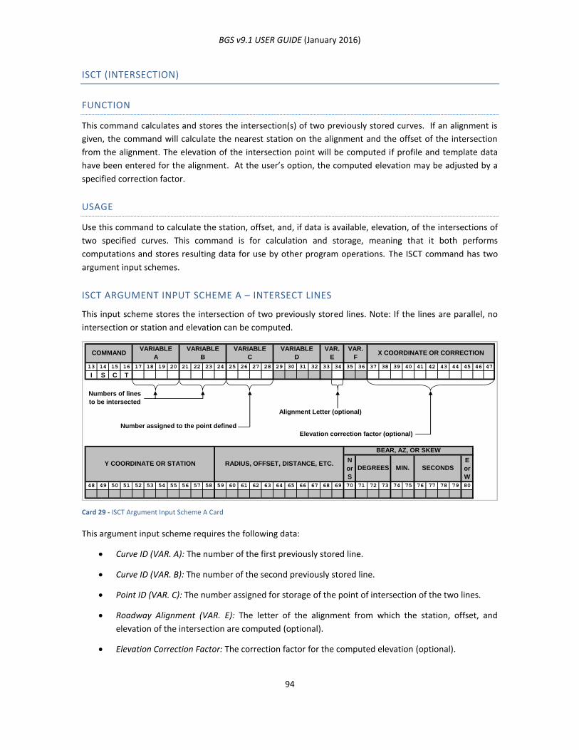
BGS v9.1 USER GUIDE (January 2016)
94
ISCT (INTERSECTION)
FUNCTION
This command calculates and stores the intersection(s) of two previously stored curves. If an alignment is
given, the command will calculate the nearest station on the alignment and the offset of the intersection
from the alignment. The elevation of the intersection point will be computed if profile and template data
have been entered for the alignment. At the user’s option, the computed elevation may be adjusted by a
specified correction factor.
USAGE
Use this command to calculate the station, offset, and, if data is available, elevation, of the intersections of
two specified curves. This command is for calculation and storage, meaning that it both performs
computations and stores resulting data for use by other program operations. The ISCT command has two
argument input schemes.
ISCT ARGUMENT INPUT SCHEME A – INTERSECT LINES
This input scheme stores the intersection of two previously stored lines. Note: If the lines are parallel, no
intersection or station and elevation can be computed.
Card 29 - ISCT Argument Input Scheme A Card
This argument input scheme requires the following data:
Curve ID (VAR. A): The number of the first previously stored line.
Curve ID (VAR. B): The number of the second previously stored line.
Point ID (VAR. C): The number assigned for storage of the point of intersection of the two lines.
Roadway Alignment (VAR. E): The letter of the alignment from which the station, offset, and
elevation of the intersection are computed (optional).
Elevation Correction Factor: The correction factor for the computed elevation (optional).
13 14 15 16 17 18 19 20 21 22 23 24 25 26 27 28 29 30 31 32 33 34 35 36 37 38 39 40 41 42 43 44 45 46 47
I S C T
Numbers of lines
to be intersected
Alignment Letter (optional)
Number assigned to the point defined
Elevation correction factor (optional)
N
or
S
E
or
W
48 49 50 51 52 53 54 55 56 57 58 59 60 61 62 63 64 65 66 67 68 69 70 71 72 73 74 75 76 77 78 79 80
Y COORDINATE OR STATION RADIUS, OFFSET, DISTANCE, ETC.DEGREES MIN. SECONDS
BEAR, AZ, OR SKEW
X COORDINATE OR CORRECTIONVAR.
F
VARIABLE
ACOMMAND
VAR.
E
VARIABLE
D
VARIABLE
C
VARIABLE
B
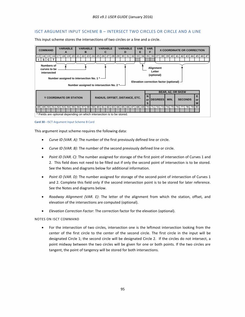
BGS v9.1 USER GUIDE (January 2016)
95
ISCT ARGUMENT INPUT SCHEME B – INTERSECT TWO CIRCLES OR CIRCLE AND A LINE
This input scheme stores the intersections of two circles or a line and a circle.
Card 30 - ISCT Argument Input Scheme B Card
This argument input scheme requires the following data:
Curve ID (VAR. A): The number of the first previously defined line or circle.
Curve ID (VAR. B): The number of the second previously defined line or circle.
Point ID (VAR. C): The number assigned for storage of the first point of intersection of Curves 1 and
2. This field does not need to be filled out if only the second point of intersection is to be stored.
See the Notes and diagrams below for additional information.
Point ID (VAR. D): The number assigned for storage of the second point of intersection of Curves 1
and 2. Complete this field only if the second intersection point is to be stored for later reference.
See the Notes and diagrams below.
Roadway Alignment (VAR. E): The letter of the alignment from which the station, offset, and
elevation of the intersections are computed (optional).
Elevation Correction Factor: The correction factor for the elevation (optional).
NOTES ON ISCT COMMAND
For the intersection of two circles, intersection one is the leftmost intersection looking from the
center of the first circle to the center of the second circle. The first circle in the input will be
designated Circle 1; the second circle will be designated Circle 2. If the circles do not intersect, a
point midway between the two circles will be given for one or both points. If the two circles are
tangent, the point of tangency will be stored for both intersections.
13 14 15 16 17 18 19 20 21 22 23 24 25 26 27 28 29 30 31 32 33 34 35 36 37 38 39 40 41 42 43 44 45 46 47
I S C T
Numbers of
curves to be
intersected
Alignment
Letter
(optional)
Number assigned to intersection No. 1 *
Elevation correction factor (optional)
Number assigned to intersection No. 2 *
N
or
S
E
or
W
48 49 50 51 52 53 54 55 56 57 58 59 60 61 62 63 64 65 66 67 68 69 70 71 72 73 74 75 76 77 78 79 80
* Fields are optional depending on which intersection is to be stored.
COMMANDVARIABLE
A
VARIABLE
B
VARIABLE
C
VARIABLE
D
VAR.
E
VAR.
FX COORDINATE OR CORRECTION
SECONDS
BEAR, AZ, OR SKEW
Y COORDINATE OR STATION RADIUS, OFFSET, DISTANCE, ETC.DEGREES MIN.
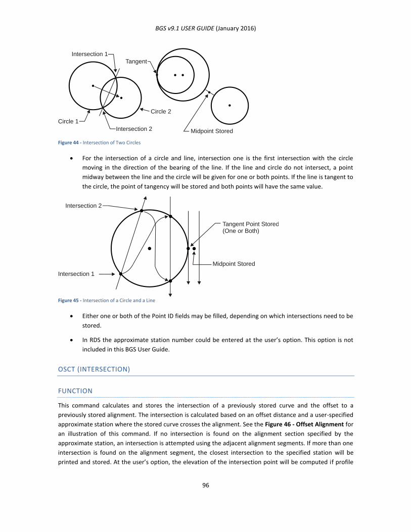
BGS v9.1 USER GUIDE (January 2016)
96
Figure 44 - Intersection of Two Circles
For the intersection of a circle and line, intersection one is the first intersection with the circle
moving in the direction of the bearing of the line. If the line and circle do not intersect, a point
midway between the line and the circle will be given for one or both points. If the line is tangent to
the circle, the point of tangency will be stored and both points will have the same value.
Figure 45 - Intersection of a Circle and a Line
Either one or both of the Point ID fields may be filled, depending on which intersections need to be
stored.
In RDS the approximate station number could be entered at the user’s option. This option is not
included in this BGS User Guide.
OSCT (INTERSECTION)
FUNCTION
This command calculates and stores the intersection of a previously stored curve and the offset to a
previously stored alignment. The intersection is calculated based on an offset distance and a user-specified
approximate station where the stored curve crosses the alignment. See the Figure 46 - Offset Alignment for
an illustration of this command. If no intersection is found on the alignment section specified by the
approximate station, an intersection is attempted using the adjacent alignment segments. If more than one
intersection is found on the alignment segment, the closest intersection to the specified station will be
printed and stored. At the user’s option, the elevation of the intersection point will be computed if profile
Intersection 1
Intersection 2
Tangent
Circle 1
Circle 2
Midpoint Stored
Intersection 1
Intersection 2
Tangent Point Stored(One or Both)
Midpoint Stored
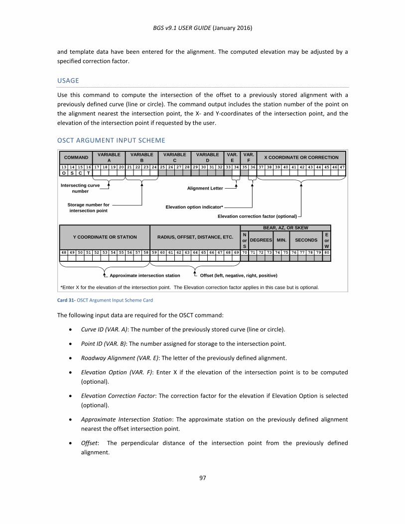
BGS v9.1 USER GUIDE (January 2016)
97
and template data have been entered for the alignment. The computed elevation may be adjusted by a
specified correction factor.
USAGE
Use this command to compute the intersection of the offset to a previously stored alignment with a
previously defined curve (line or circle). The command output includes the station number of the point on
the alignment nearest the intersection point, the X- and Y-coordinates of the intersection point, and the
elevation of the intersection point if requested by the user.
OSCT ARGUMENT INPUT SCHEME
Card 31- OSCT Argument Input Scheme Card
The following input data are required for the OSCT command:
Curve ID (VAR. A): The number of the previously stored curve (line or circle).
Point ID (VAR. B): The number assigned for storage to the intersection point.
Roadway Alignment (VAR. E): The letter of the previously defined alignment.
Elevation Option (VAR. F): Enter X if the elevation of the intersection point is to be computed
(optional).
Elevation Correction Factor: The correction factor for the elevation if Elevation Option is selected
(optional).
Approximate Intersection Station: The approximate station on the previously defined alignment
nearest the offset intersection point.
Offset: The perpendicular distance of the intersection point from the previously defined
alignment.
13 14 15 16 17 18 19 20 21 22 23 24 25 26 27 28 29 30 31 32 33 34 35 36 37 38 39 40 41 42 43 44 45 46 47
O S C T
Intersecting curve
numberAlignment Letter
Storage number for
intersection pointElevation option indicator*
Elevation correction factor (optional)
N
or
S
E
or
W
48 49 50 51 52 53 54 55 56 57 58 59 60 61 62 63 64 65 66 67 68 69 70 71 72 73 74 75 76 77 78 79 80
Approximate intersection station Offset (left, negative, right, positive)
*Enter X for the elevation of the intersection point. The Elevation correction factor applies in this case but is optional.
VARIABLE
ACOMMAND
VAR.
E
VARIABLE
D
VARIABLE
C
VARIABLE
B
SECONDS
BEAR, AZ, OR SKEW
X COORDINATE OR CORRECTION
MIN.
VAR.
F
Y COORDINATE OR STATION RADIUS, OFFSET, DISTANCE, ETC.DEGREES
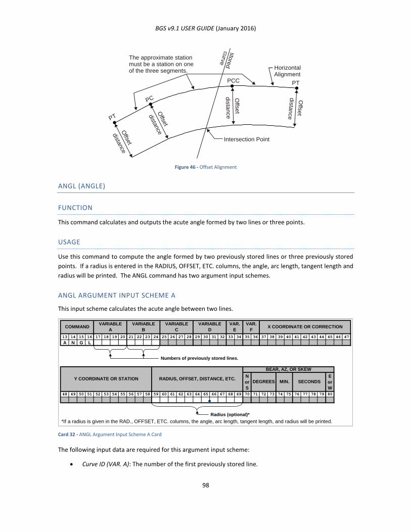
BGS v9.1 USER GUIDE (January 2016)
98
Figure 46 - Offset Alignment
ANGL (ANGLE)
FUNCTION
This command calculates and outputs the acute angle formed by two lines or three points.
USAGE
Use this command to compute the angle formed by two previously stored lines or three previously stored
points. If a radius is entered in the RADIUS, OFFSET, ETC. columns, the angle, arc length, tangent length and
radius will be printed. The ANGL command has two argument input schemes.
ANGL ARGUMENT INPUT SCHEME A
This input scheme calculates the acute angle between two lines.
Card 32 - ANGL Argument Input Scheme A Card
The following input data are required for this argument input scheme:
Curve ID (VAR. A): The number of the first previously stored line.
The approximate stationmust be a station on oneof the three segments.
HorizontalAlignment
Intersection Point
PTPCC
sto
red
curv
e
PC
PT
Offse
t
Offse
t
Offs
et
Offs
et
dista
nce
dista
nce
dis
tance
dis
tance
13 14 15 16 17 18 19 20 21 22 23 24 25 26 27 28 29 30 31 32 33 34 35 36 37 38 39 40 41 42 43 44 45 46 47
A N G L
Numbers of previously stored lines.
N
or
S
E
or
W
48 49 50 51 52 53 54 55 56 57 58 59 60 61 62 63 64 65 66 67 68 69 70 71 72 73 74 75 76 77 78 79 80
Radius (optional)*
*If a radius is given in the RAD., OFFSET, ETC. columns, the angle, arc length, tangent length, and radius will be printed.
VARIABLE
ACOMMAND
VAR.
E
VARIABLE
D
VARIABLE
C
VARIABLE
B
SECONDS
BEAR, AZ, OR SKEW
X COORDINATE OR CORRECTIONVAR.
F
Y COORDINATE OR STATION RADIUS, OFFSET, DISTANCE, ETC.DEGREES MIN.
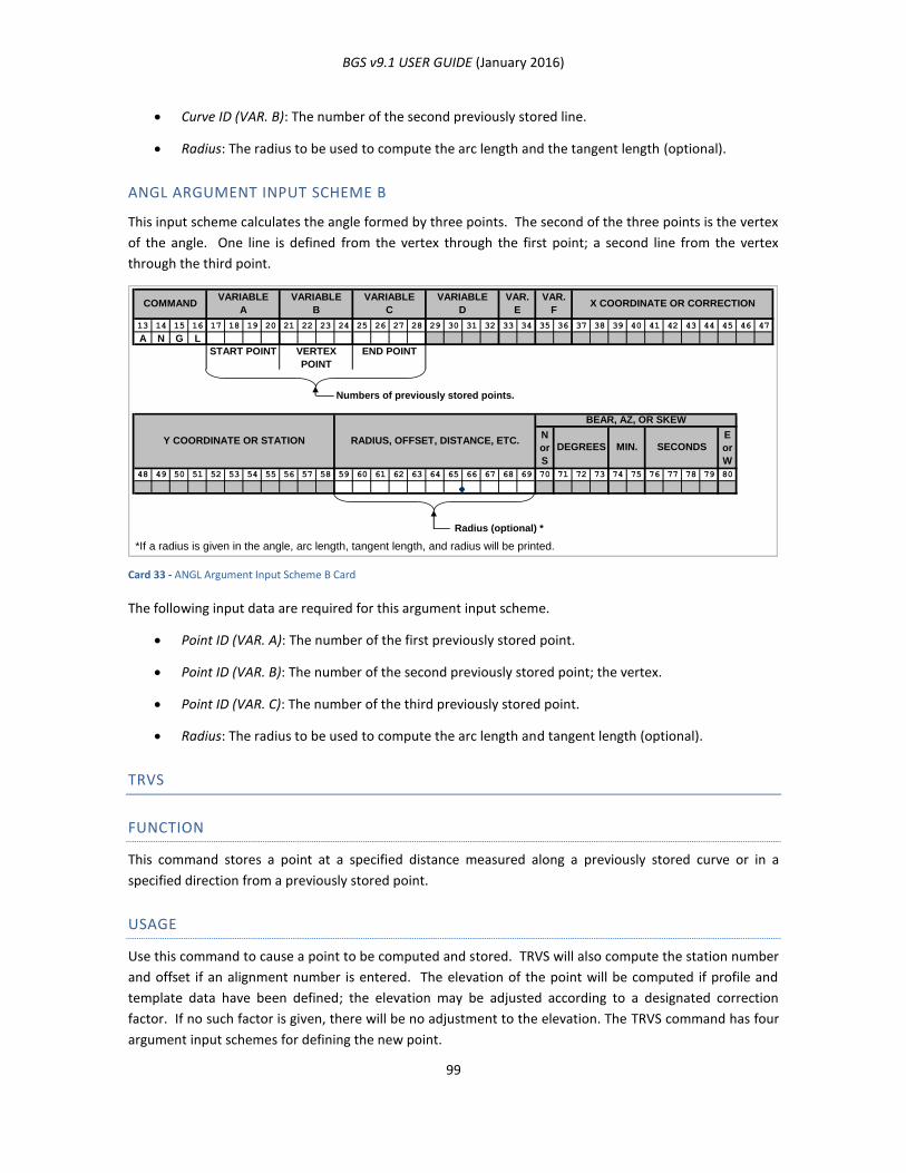
BGS v9.1 USER GUIDE (January 2016)
99
Curve ID (VAR. B): The number of the second previously stored line.
Radius: The radius to be used to compute the arc length and the tangent length (optional).
ANGL ARGUMENT INPUT SCHEME B
This input scheme calculates the angle formed by three points. The second of the three points is the vertex
of the angle. One line is defined from the vertex through the first point; a second line from the vertex
through the third point.
Card 33 - ANGL Argument Input Scheme B Card
The following input data are required for this argument input scheme.
Point ID (VAR. A): The number of the first previously stored point.
Point ID (VAR. B): The number of the second previously stored point; the vertex.
Point ID (VAR. C): The number of the third previously stored point.
Radius: The radius to be used to compute the arc length and tangent length (optional).
TRVS
FUNCTION
This command stores a point at a specified distance measured along a previously stored curve or in a
specified direction from a previously stored point.
USAGE
Use this command to cause a point to be computed and stored. TRVS will also compute the station number
and offset if an alignment number is entered. The elevation of the point will be computed if profile and
template data have been defined; the elevation may be adjusted according to a designated correction
factor. If no such factor is given, there will be no adjustment to the elevation. The TRVS command has four
argument input schemes for defining the new point.
13 14 15 16 17 18 19 20 21 22 23 24 25 26 27 28 29 30 31 32 33 34 35 36 37 38 39 40 41 42 43 44 45 46 47
A N G L
START POINT VERTEX
POINT
END POINT
Numbers of previously stored points.
N
or
S
E
or
W
48 49 50 51 52 53 54 55 56 57 58 59 60 61 62 63 64 65 66 67 68 69 70 71 72 73 74 75 76 77 78 79 80
Radius (optional) *
*If a radius is given in the angle, arc length, tangent length, and radius will be printed.
VARIABLE
D
VAR.
E
VAR.
FX COORDINATE OR CORRECTIONCOMMAND
VARIABLE
A
VARIABLE
B
VARIABLE
C
Y COORDINATE OR STATION RADIUS, OFFSET, DISTANCE, ETC.DEGREES MIN.
BEAR, AZ, OR SKEW
SECONDS
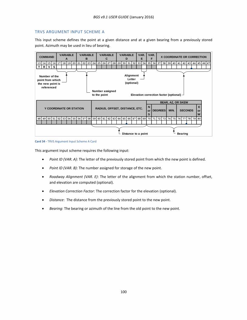
BGS v9.1 USER GUIDE (January 2016)
100
TRVS ARGUMENT INPUT SCHEME A
This input scheme defines the point at a given distance and at a given bearing from a previously stored
point. Azimuth may be used in lieu of bearing.
Card 34 - TRVS Argument Input Scheme A Card
This argument input scheme requires the following input:
Point ID (VAR. A): The letter of the previously stored point from which the new point is defined.
Point ID (VAR. B): The number assigned for storage of the new point.
Roadway Alignment (VAR. E): The letter of the alignment from which the station number, offset,
and elevation are computed (optional).
Elevation Correction Factor: The correction factor for the elevation (optional).
Distance: The distance from the previously stored point to the new point.
Bearing: The bearing or azimuth of the line from the old point to the new point.
13 14 15 16 17 18 19 20 21 22 23 24 25 26 27 28 29 30 31 32 33 34 35 36 37 38 39 40 41 42 43 44 45 46 47
T R V S
Alignment
Letter
(optional)
Elevation correction factor (optional)
N
or
S
E
or
W
48 49 50 51 52 53 54 55 56 57 58 59 60 61 62 63 64 65 66 67 68 69 70 71 72 73 74 75 76 77 78 79 80
Distance to a point Bearing
Number of the
point from which
the new point is
referenced
Number assigned
to the point
X COORDINATE OR CORRECTIONVAR.
F
VAR.
E
VARIABLE
D
VARIABLE
C
VARIABLE
B
VARIABLE
ACOMMAND
Y COORDINATE OR STATION RADIUS, OFFSET, DISTANCE, ETC.DEGREES
BEAR, AZ, OR SKEW
SECONDSMIN.
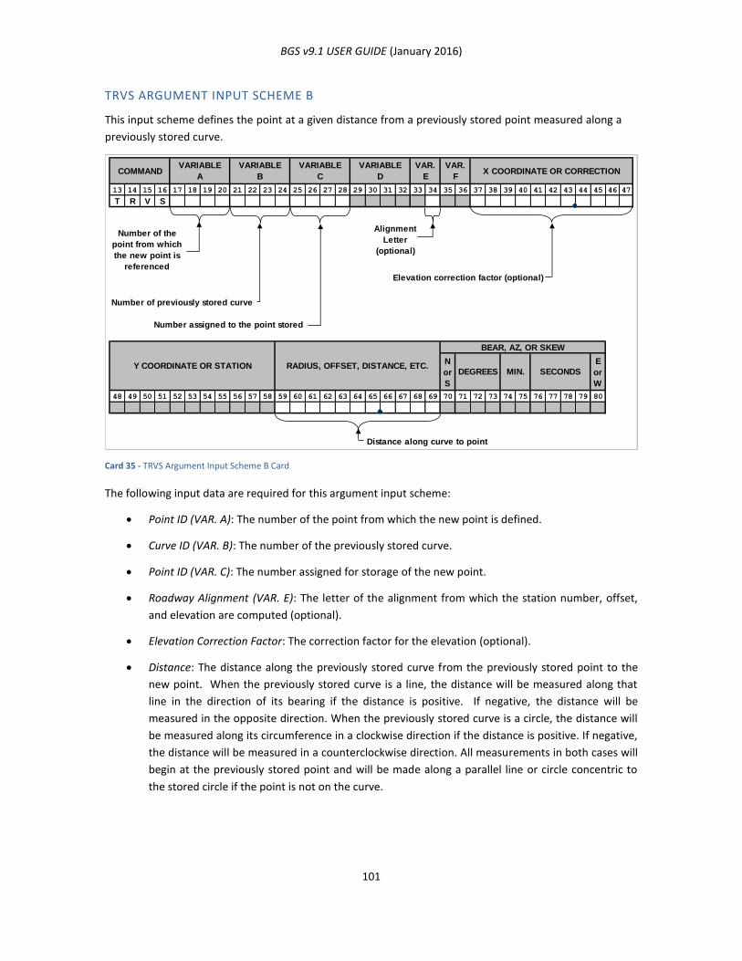
BGS v9.1 USER GUIDE (January 2016)
101
TRVS ARGUMENT INPUT SCHEME B
This input scheme defines the point at a given distance from a previously stored point measured along a
previously stored curve.
Card 35 - TRVS Argument Input Scheme B Card
The following input data are required for this argument input scheme:
Point ID (VAR. A): The number of the point from which the new point is defined.
Curve ID (VAR. B): The number of the previously stored curve.
Point ID (VAR. C): The number assigned for storage of the new point.
Roadway Alignment (VAR. E): The letter of the alignment from which the station number, offset,
and elevation are computed (optional).
Elevation Correction Factor: The correction factor for the elevation (optional).
Distance: The distance along the previously stored curve from the previously stored point to the
new point. When the previously stored curve is a line, the distance will be measured along that
line in the direction of its bearing if the distance is positive. If negative, the distance will be
measured in the opposite direction. When the previously stored curve is a circle, the distance will
be measured along its circumference in a clockwise direction if the distance is positive. If negative,
the distance will be measured in a counterclockwise direction. All measurements in both cases will
begin at the previously stored point and will be made along a parallel line or circle concentric to
the stored circle if the point is not on the curve.
13 14 15 16 17 18 19 20 21 22 23 24 25 26 27 28 29 30 31 32 33 34 35 36 37 38 39 40 41 42 43 44 45 46 47
T R V S
Alignment
Letter
(optional)
Number of previously stored curve
Elevation correction factor (optional)
Number assigned to the point stored
N
or
S
E
or
W
48 49 50 51 52 53 54 55 56 57 58 59 60 61 62 63 64 65 66 67 68 69 70 71 72 73 74 75 76 77 78 79 80
Distance along curve to point
SECONDS
BEAR, AZ, OR SKEW
Y COORDINATE OR STATION RADIUS, OFFSET, DISTANCE, ETC.DEGREES MIN.
Number of the
point from which
the new point is
referenced
X COORDINATE OR CORRECTIONVAR.
F
VAR.
E
VARIABLE
D
VARIABLE
C
VARIABLE
B
VARIABLE
ACOMMAND

BGS v9.1 USER GUIDE (January 2016)
102
TRVS ARGUMENT INPUT SCHEME C
This input scheme defines the point using two previously stored points, a distance and an angle right
(clockwise) or left (counterclockwise). The line from the first previously stored point through the second
forms one side of an angle. The line from the second previously stored point at the given angle from the
first line forms the second side of the angle. Then the newly defined point is at the given distance from
the vertex (the second point) along the second side of the angle. The output distance will be the distance
from the vertex to the newly defined point. See Figure 47 - Distance and Angle Examples.
Card 36 - TRVS Argument Input Scheme C Card
This argument input scheme requires the following data:
Point ID (VAR. A): The previously stored number of the first point on the first side of the angle.
Point ID (VAR. B): The previously stored number of the second point on the first side of the angle
forming the vertex of the angle. The distance to the new point will be measured from this point.
Point ID (VAR. C): The number assigned for storage of the new point.
Roadway Alignment (VAR. E): The letter of the alignment from which the station number, offset,
and elevation are computed (optional).
Elevation Correction Factor: The correction factor for the elevation (optional).
Distance: The distance from the second point to the newly defined point.
Angle: The angle between the line defined by the second and first points and the line defined by
the second point and the new point.
Direction: The direction in which the angle is measured. Enter L for counterclockwise or R for
clockwise.
13 14 15 16 17 18 19 20 21 22 23 24 25 26 27 28 29 30 31 32 33 34 35 36 37 38 39 40 41 42 43 44 45 46 47
T R V S
Alignment
Letter
(optional)
Elevation correction factor (optional)
Number assigned to the point stored
N
or
S
E
or
W
48 49 50 51 52 53 54 55 56 57 58 59 60 61 62 63 64 65 66 67 68 69 70 71 72 73 74 75 76 77 78 79 80
Angle
Distance to a point L for left
R for right
SECONDS
BEAR, AZ, OR SKEW
X COORDINATE OR CORRECTIONVAR.
F
VAR.
E
MIN.
VARIABLE
C
VARIABLE
B
VARIABLE
ACOMMAND
VARIABLE
D
Previously stored
point
Previously stored point from
which the distance is measured
Y COORDINATE OR STATION RADIUS, OFFSET, DISTANCE, ETC.DEGREES
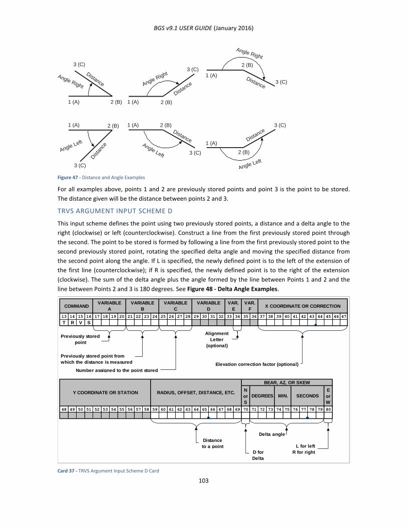
BGS v9.1 USER GUIDE (January 2016)
103
Figure 47 - Distance and Angle Examples
For all examples above, points 1 and 2 are previously stored points and point 3 is the point to be stored.
The distance given will be the distance between points 2 and 3.
TRVS ARGUMENT INPUT SCHEME D
This input scheme defines the point using two previously stored points, a distance and a delta angle to the
right (clockwise) or left (counterclockwise). Construct a line from the first previously stored point through
the second. The point to be stored is formed by following a line from the first previously stored point to the
second previously stored point, rotating the specified delta angle and moving the specified distance from
the second point along the angle. If L is specified, the newly defined point is to the left of the extension of
the first line (counterclockwise); if R is specified, the newly defined point is to the right of the extension
(clockwise). The sum of the delta angle plus the angle formed by the line between Points 1 and 2 and the
line between Points 2 and 3 is 180 degrees. See Figure 48 - Delta Angle Examples.
Card 37 - TRVS Argument Input Scheme D Card
Angle Right
Angle Left Angle Left
Angle Left
Angle Right
Angle Right
Distance
Distance
Distance
Distance
Dista
nce
Distance
3 (C)
1 (A) 2 (B) 2 (B)
2 (B) 2 (B)
2 (B)
2 (B)
1 (A)
1 (A)
1 (A)
1 (A)
1 (A)
3 (C)
3 (C)
3 (C)
3 (C)
3 (C)
13 14 15 16 17 18 19 20 21 22 23 24 25 26 27 28 29 30 31 32 33 34 35 36 37 38 39 40 41 42 43 44 45 46 47
T R V S
Alignment
Letter
(optional)
Elevation correction factor (optional)
Number assigned to the point stored
N
or
S
E
or
W
48 49 50 51 52 53 54 55 56 57 58 59 60 61 62 63 64 65 66 67 68 69 70 71 72 73 74 75 76 77 78 79 80
Delta angle
Distance
to a point L for left
D for R for right
Delta
RADIUS, OFFSET, DISTANCE, ETC.Y COORDINATE OR STATION
X COORDINATE OR CORRECTION
SECONDSMIN.
BEAR, AZ, OR SKEW
DEGREES
VARIABLE
C
VARIABLE
D
VAR.
E
VAR.
F
Previously stored
point
Previously stored point from
which the distance is measured
COMMANDVARIABLE
A
VARIABLE
B
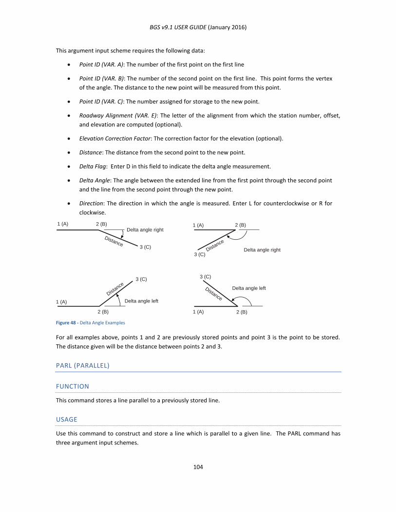
BGS v9.1 USER GUIDE (January 2016)
104
This argument input scheme requires the following data:
Point ID (VAR. A): The number of the first point on the first line
Point ID (VAR. B): The number of the second point on the first line. This point forms the vertex
of the angle. The distance to the new point will be measured from this point.
Point ID (VAR. C): The number assigned for storage to the new point.
Roadway Alignment (VAR. E): The letter of the alignment from which the station number, offset,
and elevation are computed (optional).
Elevation Correction Factor: The correction factor for the elevation (optional).
Distance: The distance from the second point to the new point.
Delta Flag: Enter D in this field to indicate the delta angle measurement.
Delta Angle: The angle between the extended line from the first point through the second point
and the line from the second point through the new point.
Direction: The direction in which the angle is measured. Enter L for counterclockwise or R for
clockwise.
Figure 48 - Delta Angle Examples
For all examples above, points 1 and 2 are previously stored points and point 3 is the point to be stored.
The distance given will be the distance between points 2 and 3.
PARL (PARALLEL)
FUNCTION
This command stores a line parallel to a previously stored line.
USAGE
Use this command to construct and store a line which is parallel to a given line. The PARL command has
three argument input schemes.
Delta angle right
Delta angle right
Delta angle left
Delta angle left
DistanceDist
ance
Distance
Distance
3 (C)
1 (A)
2 (B) 2 (B)
2 (B) 2 (B)1 (A)
1 (A)
1 (A)
3 (C)
3 (C)
3 (C)
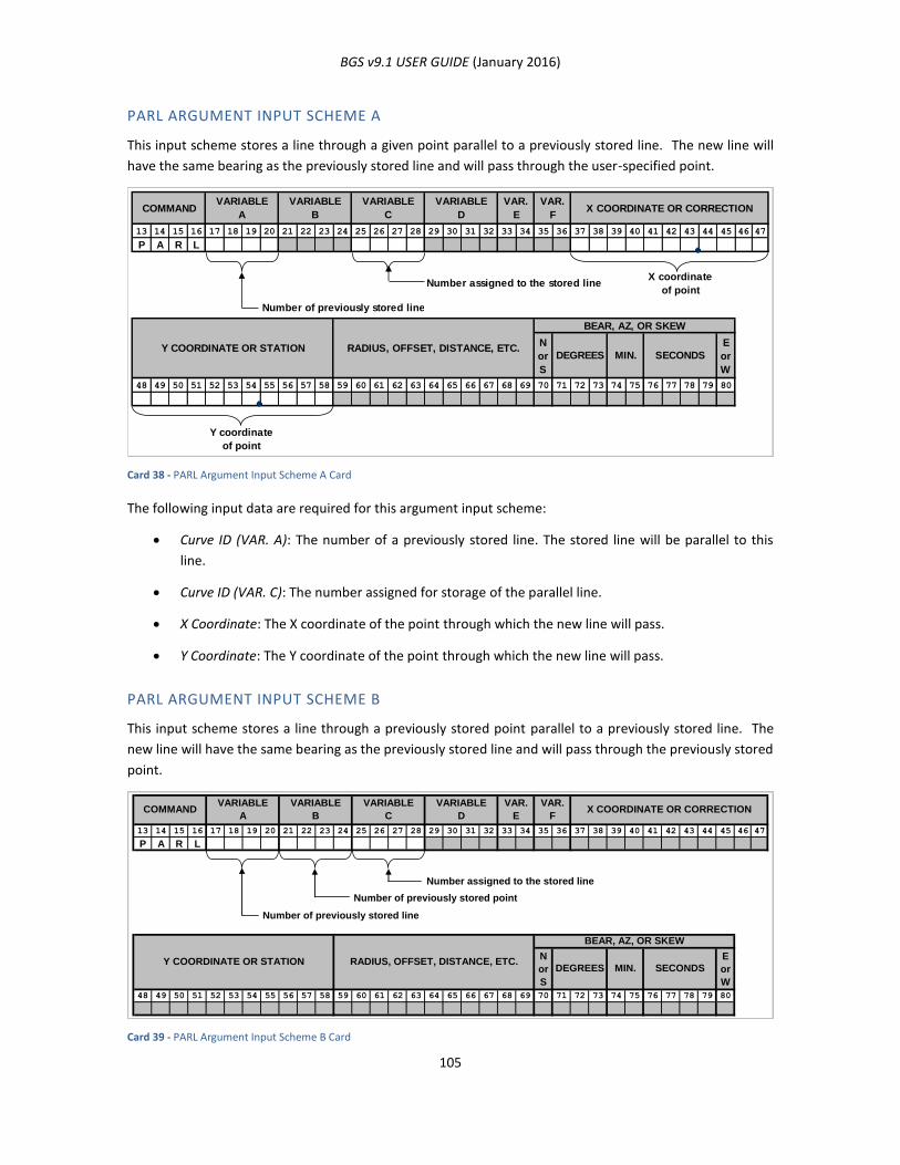
BGS v9.1 USER GUIDE (January 2016)
105
PARL ARGUMENT INPUT SCHEME A
This input scheme stores a line through a given point parallel to a previously stored line. The new line will
have the same bearing as the previously stored line and will pass through the user-specified point.
Card 38 - PARL Argument Input Scheme A Card
The following input data are required for this argument input scheme:
Curve ID (VAR. A): The number of a previously stored line. The stored line will be parallel to this
line.
Curve ID (VAR. C): The number assigned for storage of the parallel line.
X Coordinate: The X coordinate of the point through which the new line will pass.
Y Coordinate: The Y coordinate of the point through which the new line will pass.
PARL ARGUMENT INPUT SCHEME B
This input scheme stores a line through a previously stored point parallel to a previously stored line. The
new line will have the same bearing as the previously stored line and will pass through the previously stored
point.
Card 39 - PARL Argument Input Scheme B Card
13 14 15 16 17 18 19 20 21 22 23 24 25 26 27 28 29 30 31 32 33 34 35 36 37 38 39 40 41 42 43 44 45 46 47
P A R L
Number of previously stored line
Number assigned to the stored lineX coordinate
of point
N
or
S
E
or
W
48 49 50 51 52 53 54 55 56 57 58 59 60 61 62 63 64 65 66 67 68 69 70 71 72 73 74 75 76 77 78 79 80
Y coordinate
of point
X COORDINATE OR CORRECTIONVARIABLE
A
VARIABLE
B
Y COORDINATE OR STATIONDEGREES MIN. SECONDS
BEAR, AZ, OR SKEW
RADIUS, OFFSET, DISTANCE, ETC.
VARIABLE
CCOMMAND
VARIABLE
D
VAR.
E
VAR.
F
13 14 15 16 17 18 19 20 21 22 23 24 25 26 27 28 29 30 31 32 33 34 35 36 37 38 39 40 41 42 43 44 45 46 47
P A R L
Number assigned to the stored line
Number of previously stored point
Number of previously stored line
N
or
S
E
or
W
48 49 50 51 52 53 54 55 56 57 58 59 60 61 62 63 64 65 66 67 68 69 70 71 72 73 74 75 76 77 78 79 80
VAR.
FX COORDINATE OR CORRECTION
RADIUS, OFFSET, DISTANCE, ETC.Y COORDINATE OR STATION
COMMANDVARIABLE
A
VARIABLE
B
VARIABLE
C
VARIABLE
D
VAR.
E
SECONDSMIN.
BEAR, AZ, OR SKEW
DEGREES
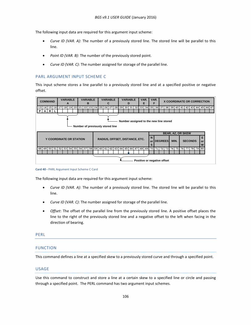
BGS v9.1 USER GUIDE (January 2016)
106
The following input data are required for this argument input scheme:
Curve ID (VAR. A): The number of a previously stored line. The stored line will be parallel to this
line.
Point ID (VAR. B): The number of the previously stored point.
Curve ID (VAR. C): The number assigned for storage of the parallel line.
PARL ARGUMENT INPUT SCHEME C
This input scheme stores a line parallel to a previously stored line and at a specified positive or negative
offset.
Card 40 - PARL Argument Input Scheme C Card
The following input data are required for this argument input scheme:
Curve ID (VAR. A): The number of a previously stored line. The stored line will be parallel to this
line.
Curve ID (VAR. C): The number assigned for storage of the parallel line.
Offset: The offset of the parallel line from the previously stored line. A positive offset places the
line to the right of the previously stored line and a negative offset to the left when facing in the
direction of bearing.
PERL
FUNCTION
This command defines a line at a specified skew to a previously stored curve and through a specified point.
USAGE
Use this command to construct and store a line at a certain skew to a specified line or circle and passing
through a specified point. The PERL command has two argument input schemes.
13 14 15 16 17 18 19 20 21 22 23 24 25 26 27 28 29 30 31 32 33 34 35 36 37 38 39 40 41 42 43 44 45 46 47
P A R L
Number assigned to the new line stored
Number of previously stored line
N
or
S
E
or
W
48 49 50 51 52 53 54 55 56 57 58 59 60 61 62 63 64 65 66 67 68 69 70 71 72 73 74 75 76 77 78 79 80
Positive or negative offset
RADIUS, OFFSET, DISTANCE, ETC.Y COORDINATE OR STATION
BEAR, AZ, OR SKEW
SECONDSMIN.DEGREES
VARIABLE
D
VAR.
E
VAR.
FX COORDINATE OR CORRECTIONCOMMAND
VARIABLE
A
VARIABLE
B
VARIABLE
C
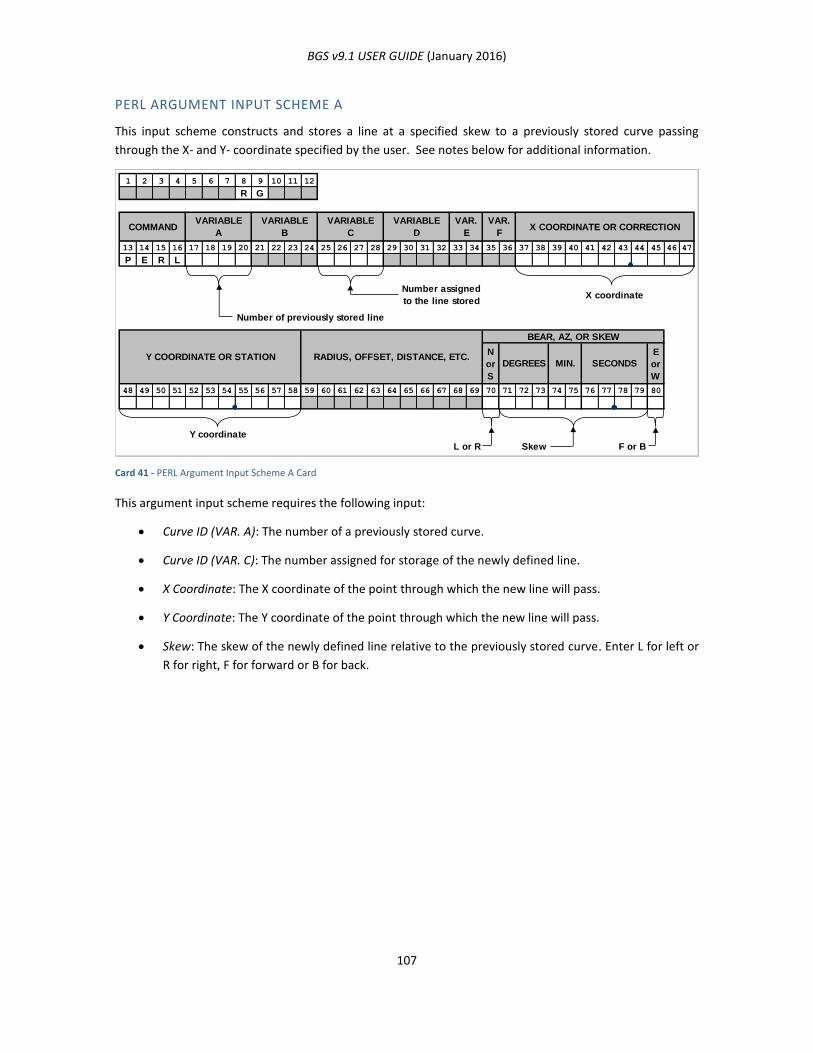
BGS v9.1 USER GUIDE (January 2016)
107
PERL ARGUMENT INPUT SCHEME A
This input scheme constructs and stores a line at a specified skew to a previously stored curve passing
through the X- and Y- coordinate specified by the user. See notes below for additional information.
Card 41 - PERL Argument Input Scheme A Card
This argument input scheme requires the following input:
Curve ID (VAR. A): The number of a previously stored curve.
Curve ID (VAR. C): The number assigned for storage of the newly defined line.
X Coordinate: The X coordinate of the point through which the new line will pass.
Y Coordinate: The Y coordinate of the point through which the new line will pass.
Skew: The skew of the newly defined line relative to the previously stored curve. Enter L for left or
R for right, F for forward or B for back.
1 2 3 4 5 6 7 8 9 10 11 12
R G
13 14 15 16 17 18 19 20 21 22 23 24 25 26 27 28 29 30 31 32 33 34 35 36 37 38 39 40 41 42 43 44 45 46 47
P E R L
Number of previously stored line
Number assigned
to the line storedX coordinate
N
or
S
E
or
W
48 49 50 51 52 53 54 55 56 57 58 59 60 61 62 63 64 65 66 67 68 69 70 71 72 73 74 75 76 77 78 79 80
Y coordinate
L or R Skew F or B
VARIABLE
ACOMMAND X COORDINATE OR CORRECTION
VAR.
F
VAR.
E
VARIABLE
D
VARIABLE
C
VARIABLE
B
BEAR, AZ, OR SKEW
Y COORDINATE OR STATION RADIUS, OFFSET, DISTANCE, ETC.DEGREES MIN. SECONDS
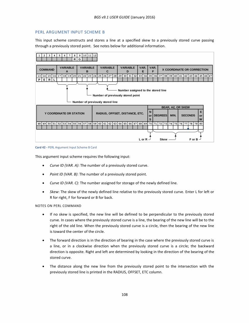
BGS v9.1 USER GUIDE (January 2016)
108
PERL ARGUMENT INPUT SCHEME B
This input scheme constructs and stores a line at a specified skew to a previously stored curve passing
through a previously stored point. See notes below for additional information.
Card 42 - PERL Argument Input Scheme B Card
This argument input scheme requires the following input:
Curve ID (VAR. A): The number of a previously stored curve.
Point ID (VAR. B): The number of a previously stored point.
Curve ID (VAR. C): The number assigned for storage of the newly defined line.
Skew: The skew of the newly defined line relative to the previously stored curve. Enter L for left or
R for right, F for forward or B for back.
NOTES ON PERL COMMAND
If no skew is specified, the new line will be defined to be perpendicular to the previously stored
curve. In cases where the previously stored curve is a line, the bearing of the new line will be to the
right of the old line. When the previously stored curve is a circle, then the bearing of the new line
is toward the center of the circle.
The forward direction is in the direction of bearing in the case where the previously stored curve is
a line, or in a clockwise direction when the previously stored curve is a circle; the backward
direction is opposite. Right and left are determined by looking in the direction of the bearing of the
stored curve.
The distance along the new line from the previously stored point to the intersection with the
previously stored line is printed in the RADIUS, OFFSET, ETC column.
1 2 3 4 5 6 7 8 9 10 11 12
R G
13 14 15 16 17 18 19 20 21 22 23 24 25 26 27 28 29 30 31 32 33 34 35 36 37 38 39 40 41 42 43 44 45 46 47
P E R L
Number assigned to the stored line
Number of previously stored point
Number of previously stored line
N
or
S
E
or
W
48 49 50 51 52 53 54 55 56 57 58 59 60 61 62 63 64 65 66 67 68 69 70 71 72 73 74 75 76 77 78 79 80
L or R Skew F or B
RADIUS, OFFSET, DISTANCE, ETC.Y COORDINATE OR STATIONSECONDSMIN.
BEAR, AZ, OR SKEW
DEGREES
VARIABLE
D
VAR.
E
VAR.
FX COORDINATE OR CORRECTIONCOMMAND
VARIABLE
A
VARIABLE
B
VARIABLE
C
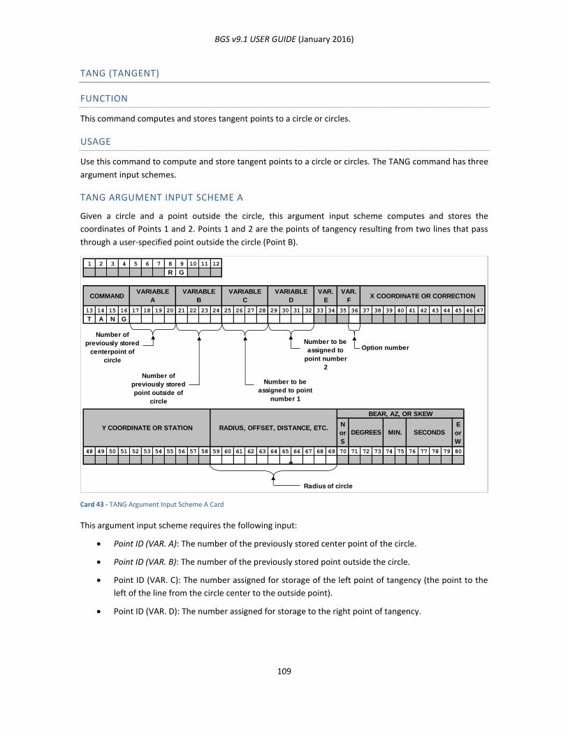
BGS v9.1 USER GUIDE (January 2016)
109
TANG (TANGENT)
FUNCTION
This command computes and stores tangent points to a circle or circles.
USAGE
Use this command to compute and store tangent points to a circle or circles. The TANG command has three
argument input schemes.
TANG ARGUMENT INPUT SCHEME A
Given a circle and a point outside the circle, this argument input scheme computes and stores the
coordinates of Points 1 and 2. Points 1 and 2 are the points of tangency resulting from two lines that pass
through a user-specified point outside the circle (Point B).
Card 43 - TANG Argument Input Scheme A Card
This argument input scheme requires the following input:
Point ID (VAR. A): The number of the previously stored center point of the circle.
Point ID (VAR. B): The number of the previously stored point outside the circle.
Point ID (VAR. C): The number assigned for storage of the left point of tangency (the point to the
left of the line from the circle center to the outside point).
Point ID (VAR. D): The number assigned for storage to the right point of tangency.
1 2 3 4 5 6 7 8 9 10 11 12
R G
13 14 15 16 17 18 19 20 21 22 23 24 25 26 27 28 29 30 31 32 33 34 35 36 37 38 39 40 41 42 43 44 45 46 47
T A N G
Number to be
assigned to
point number
2
Option number
N
or
S
E
or
W
48 49 50 51 52 53 54 55 56 57 58 59 60 61 62 63 64 65 66 67 68 69 70 71 72 73 74 75 76 77 78 79 80
Radius of circle
VARIABLE
A
VARIABLE
B
Y COORDINATE OR STATION
VAR.
E
VAR.
F
RADIUS, OFFSET, DISTANCE, ETC.
Number to be
assigned to point
number 1
VARIABLE
C
VARIABLE
D
Number of
previously stored
centerpoint of
circle
Number of
previously stored
point outside of
circle
COMMAND X COORDINATE OR CORRECTION
SECONDSMIN.DEGREES
BEAR, AZ, OR SKEW
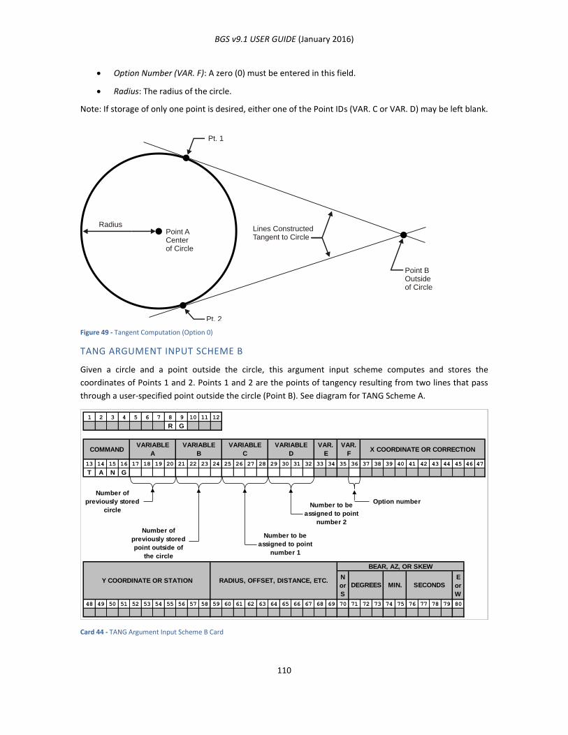
BGS v9.1 USER GUIDE (January 2016)
110
Option Number (VAR. F): A zero (0) must be entered in this field.
Radius: The radius of the circle.
Note: If storage of only one point is desired, either one of the Point IDs (VAR. C or VAR. D) may be left blank.
Figure 49 - Tangent Computation (Option 0)
TANG ARGUMENT INPUT SCHEME B
Given a circle and a point outside the circle, this argument input scheme computes and stores the
coordinates of Points 1 and 2. Points 1 and 2 are the points of tangency resulting from two lines that pass
through a user-specified point outside the circle (Point B). See diagram for TANG Scheme A.
Card 44 - TANG Argument Input Scheme B Card
Pt. 1
RadiusPoint ACenterof Circle
Pt. 2
Point BOutsideof Circle
Lines ConstructedTangent to Circle
1 2 3 4 5 6 7 8 9 10 11 12
R G
13 14 15 16 17 18 19 20 21 22 23 24 25 26 27 28 29 30 31 32 33 34 35 36 37 38 39 40 41 42 43 44 45 46 47
T A N G
Number to be
assigned to point
number 2
Option number
N
or
S
E
or
W
48 49 50 51 52 53 54 55 56 57 58 59 60 61 62 63 64 65 66 67 68 69 70 71 72 73 74 75 76 77 78 79 80
VARIABLE
D
VAR.
E
VAR.
FX COORDINATE OR CORRECTION
BEAR, AZ, OR SKEW
Y COORDINATE OR STATIONSECONDSMIN.DEGREES
RADIUS, OFFSET, DISTANCE, ETC.
Number of
previously stored
circle
Number of
previously stored
point outside of
the circle
Number to be
assigned to point
number 1
COMMANDVARIABLE
A
VARIABLE
B
VARIABLE
C
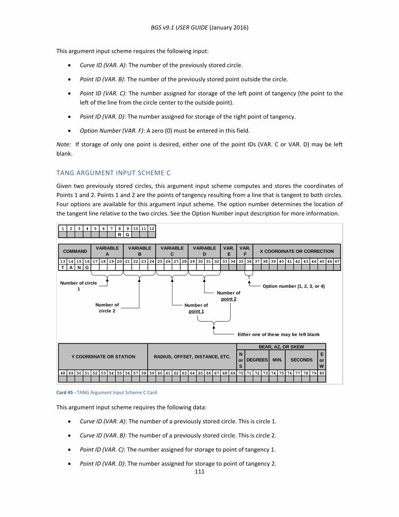
BGS v9.1 USER GUIDE (January 2016)
111
This argument input scheme requires the following input:
Curve ID (VAR. A): The number of the previously stored circle.
Point ID (VAR. B): The number of the previously stored point outside the circle.
Point ID (VAR. C): The number assigned for storage of the left point of tangency (the point to the
left of the line from the circle center to the outside point).
Point ID (VAR. D): The number assigned for storage of the right point of tangency.
Option Number (VAR. F): A zero (0) must be entered in this field.
Note: If storage of only one point is desired, either one of the point IDs (VAR. C or VAR. D) may be left
blank.
TANG ARGUMENT INPUT SCHEME C
Given two previously stored circles, this argument input scheme computes and stores the coordinates of
Points 1 and 2. Points 1 and 2 are the points of tangency resulting from a line that is tangent to both circles.
Four options are available for this argument input scheme. The option number determines the location of
the tangent line relative to the two circles. See the Option Number input description for more information.
Card 45 - TANG Argument Input Scheme C Card
This argument input scheme requires the following data:
Curve ID (VAR. A): The number of a previously stored circle. This is circle 1.
Curve ID (VAR. B): The number of a previously stored circle. This is circle 2.
Point ID (VAR. C): The number assigned for storage to point of tangency 1.
Point ID (VAR. D): The number assigned for storage to point of tangency 2.
1 2 3 4 5 6 7 8 9 10 11 12
R G
13 14 15 16 17 18 19 20 21 22 23 24 25 26 27 28 29 30 31 32 33 34 35 36 37 38 39 40 41 42 43 44 45 46 47
T A N G
Number of
point 2
Option number (1, 2, 3, or 4)
Number of
circle 2
Number of
point 1
Either one of these may be left blank
N
or
S
E
or
W
48 49 50 51 52 53 54 55 56 57 58 59 60 61 62 63 64 65 66 67 68 69 70 71 72 73 74 75 76 77 78 79 80
X COORDINATE OR CORRECTION
BEAR, AZ, OR SKEW
SECONDSMIN.DEGREES
VAR.
F
Number of circle
1
COMMANDVARIABLE
A
VARIABLE
B
RADIUS, OFFSET, DISTANCE, ETC.Y COORDINATE OR STATION
VARIABLE
C
VARIABLE
D
VAR.
E

BGS v9.1 USER GUIDE (January 2016)
112
Option Number (VAR. F): Reference the following diagram. This field specifies which two of the
four computed points of tangency are to be stored. In the following discussion, “left” and “right”
are defined by the line from the center of circle 1 to the center of circle 2. Available option
numbers and descriptions are as follows:
Option 1: The points stored are those to the left of both circles. The first point is to the left of
circle 1 and the second to the left of circle 2.
Option 2: The points stored are those to the right of both circles. The first point is to the left of
circle 1 and the second to the left of circle 2.
Option 3: The first point stored is to the left of circle 1. The second point stored is to the right of
circle 2.
Option 4: The first point stored is to the right of circle 1. The second point stored is to the left of
circle 2.
Note: A point on the circumference of circle 1 will be stored by the number entered as VAR. C. If no
number appears in this field, the point will not be stored. A point on the circumference of circle two will be
stored by the number entered as VAR. D. If no number appears in this field, the point will not be stored.
Either or both points may be stored.
Figure 50 - Tangent Computation (Options 1-4)
Pt. 1
Pt. 2
Pt. 2
Pt. 2
Pt. 2
Pt. 1
Pt. 1
Circle 1 Circle 2
Opt. 1
Opt. 3
Opt. 4
Opt. 2
Pt. 1
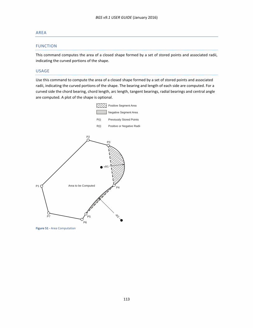
BGS v9.1 USER GUIDE (January 2016)
113
AREA
FUNCTION
This command computes the area of a closed shape formed by a set of stored points and associated radii,
indicating the curved portions of the shape.
USAGE
Use this command to compute the area of a closed shape formed by a set of stored points and associated
radii, indicating the curved portions of the shape. The bearing and length of each side are computed. For a
curved side the chord bearing, chord length, arc length, tangent bearings, radial bearings and central angle
are computed. A plot of the shape is optional.
Figure 51 - Area Computation
P2
Positive Segment Area
Negative Segment Area
Previously Stored PointsP(i)
Positive or Negative RadiiR(i)
P1 Area to be Computed
P3
P4
+R1
P5-R
2
P6
P7
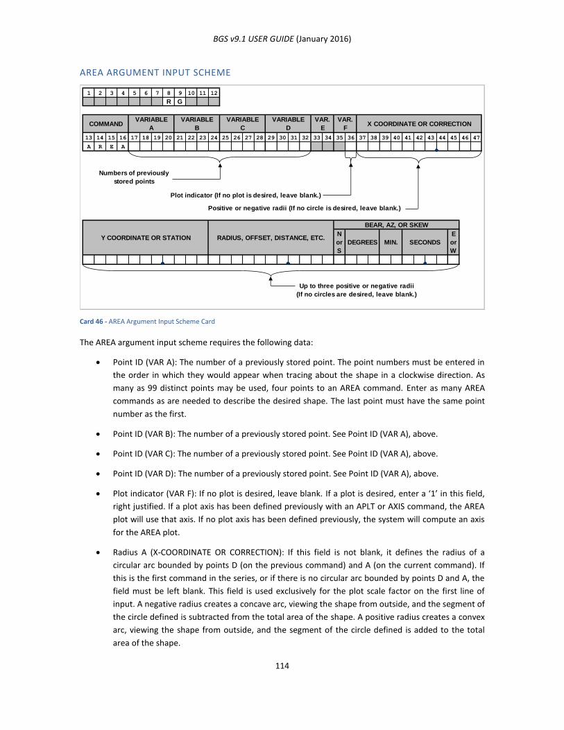
BGS v9.1 USER GUIDE (January 2016)
114
AREA ARGUMENT INPUT SCHEME
Card 46 - AREA Argument Input Scheme Card
The AREA argument input scheme requires the following data:
Point ID (VAR A): The number of a previously stored point. The point numbers must be entered in
the order in which they would appear when tracing about the shape in a clockwise direction. As
many as 99 distinct points may be used, four points to an AREA command. Enter as many AREA
commands as are needed to describe the desired shape. The last point must have the same point
number as the first.
Point ID (VAR B): The number of a previously stored point. See Point ID (VAR A), above.
Point ID (VAR C): The number of a previously stored point. See Point ID (VAR A), above.
Point ID (VAR D): The number of a previously stored point. See Point ID (VAR A), above.
Plot indicator (VAR F): If no plot is desired, leave blank. If a plot is desired, enter a ‘1’ in this field,
right justified. If a plot axis has been defined previously with an APLT or AXIS command, the AREA
plot will use that axis. If no plot axis has been defined previously, the system will compute an axis
for the AREA plot.
Radius A (X-COORDINATE OR CORRECTION): If this field is not blank, it defines the radius of a
circular arc bounded by points D (on the previous command) and A (on the current command). If
this is the first command in the series, or if there is no circular arc bounded by points D and A, the
field must be left blank. This field is used exclusively for the plot scale factor on the first line of
input. A negative radius creates a concave arc, viewing the shape from outside, and the segment of
the circle defined is subtracted from the total area of the shape. A positive radius creates a convex
arc, viewing the shape from outside, and the segment of the circle defined is added to the total
area of the shape.
1 2 3 4 5 6 7 8 9 10 11 12
R G
13 14 15 16 17 18 19 20 21 22 23 24 25 26 27 28 29 30 31 32 33 34 35 36 37 38 39 40 41 42 43 44 45 46 47
A R E A
Plot indicator (If no plot is desired, leave blank.)
Positive or negative radii (If no circle is desired, leave blank.)
N
or
S
E
or
W
Up to three positive or negative radii
(If no circles are desired, leave blank.)
Y COORDINATE OR STATION RADIUS, OFFSET, DISTANCE, ETC.
BEAR, AZ, OR SKEW
DEGREES MIN. SECONDS
X COORDINATE OR CORRECTIONCOMMAND
Numbers of previously
stored points
VARIABLE
B
VARIABLE
A
VAR.
F
VAR.
E
VARIABLE
D
VARIABLE
C
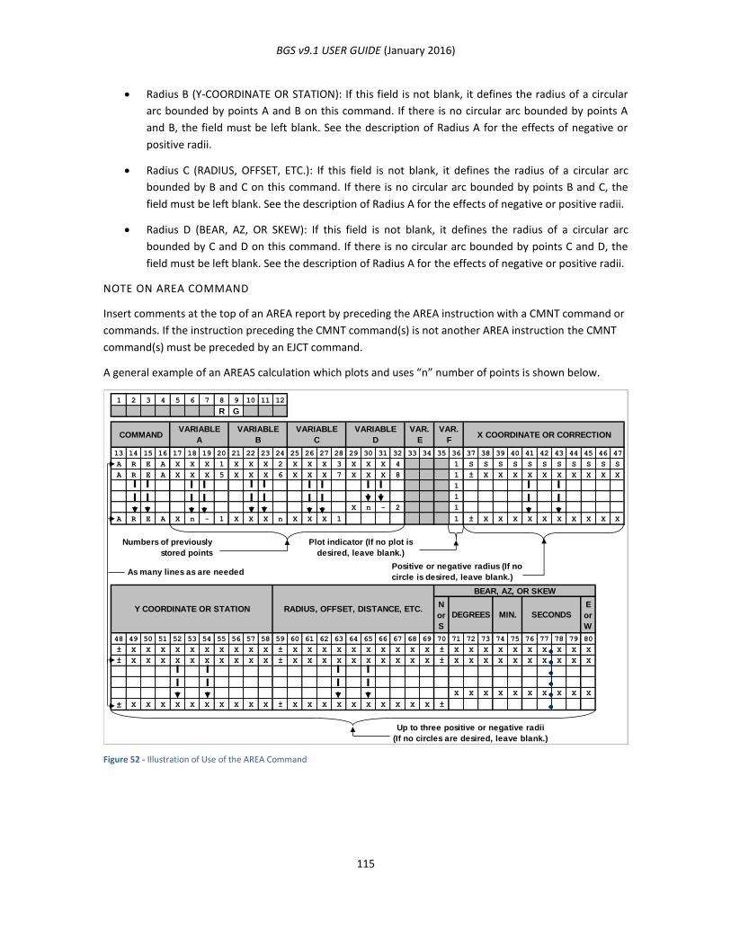
BGS v9.1 USER GUIDE (January 2016)
115
Radius B (Y-COORDINATE OR STATION): If this field is not blank, it defines the radius of a circular
arc bounded by points A and B on this command. If there is no circular arc bounded by points A
and B, the field must be left blank. See the description of Radius A for the effects of negative or
positive radii.
Radius C (RADIUS, OFFSET, ETC.): If this field is not blank, it defines the radius of a circular arc
bounded by B and C on this command. If there is no circular arc bounded by points B and C, the
field must be left blank. See the description of Radius A for the effects of negative or positive radii.
Radius D (BEAR, AZ, OR SKEW): If this field is not blank, it defines the radius of a circular arc
bounded by C and D on this command. If there is no circular arc bounded by points C and D, the
field must be left blank. See the description of Radius A for the effects of negative or positive radii.
NOTE ON AREA COMMAND
Insert comments at the top of an AREA report by preceding the AREA instruction with a CMNT command or
commands. If the instruction preceding the CMNT command(s) is not another AREA instruction the CMNT
command(s) must be preceded by an EJCT command.
A general example of an AREAS calculation which plots and uses “n” number of points is shown below.
Figure 52 - Illustration of Use of the AREA Command
1 2 3 4 5 6 7 8 9 10 11 12
R G
13 14 15 16 17 18 19 20 21 22 23 24 25 26 27 28 29 30 31 32 33 34 35 36 37 38 39 40 41 42 43 44 45 46 47
A R E A X X X 1 X X X 2 X X X 3 X X X 4 1 S S S S S S S S S S S
A R E A X X X 5 X X X 6 X X X 7 X X X 8 1 ± X X X X X X X X X X
1
1
X n - 2 1
A R E A X n - 1 X X X n X X X 1 1 ± X X X X X X X X X X
N
or
S
E
or
W
48 49 50 51 52 53 54 55 56 57 58 59 60 61 62 63 64 65 66 67 68 69 70 71 72 73 74 75 76 77 78 79 80
± X X X X X X X X X X ± X X X X X X X X X X ± X X X X X X X X X X
± X X X X X X X X X X ± X X X X X X X X X X ± X X X X X X X X X X
X X X X X X X X X X
± X X X X X X X X X X ± X X X X X X X X X X ±
Positive or negative radius (If no
circle is desired, leave blank.)
Up to three positive or negative radii
(If no circles are desired, leave blank.)
VAR.
FX COORDINATE OR CORRECTION
RADIUS, OFFSET, DISTANCE, ETC.Y COORDINATE OR STATION
COMMANDVARIABLE
A
VARIABLE
B
VARIABLE
C
VARIABLE
D
VAR.
E
SECONDSMIN.DEGREES
Plot indicator (If no plot is
desired, leave blank.)
As many lines as are needed
Numbers of previously
stored points
BEAR, AZ, OR SKEW
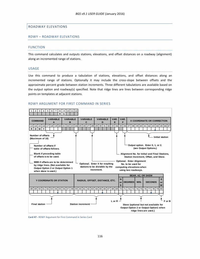
BGS v9.1 USER GUIDE (January 2016)
116
ROADWAY ELEVATIONS
RDWY – ROADWAY ELEVATIONS
FUNCTION
This command calculates and outputs stations, elevations, and offset distances on a roadway (alignment)
along an incremented range of stations.
USAGE
Use this command to produce a tabulation of stations, elevations, and offset distances along an
incremented range of stations. Optionally it may include the cross-slope between offsets and the
approximate percent grade between station increments. Three different tabulations are available based on
the output option and roadway(s) specified. Note that ridge lines are lines between corresponding ridge
points on templates at adjacent stations.
RDWY ARGUMENT FOR FIRST COMMAND IN SERIES
Card 47 - RDWY Argument for First Command in Series Card
1 2 3 4 5 6 7 8 9 10 11 12
R G
13 14 15 16 17 18 19 20 21 22 23 24 25 26 27 28 29 30 31 32 33 34 35 36 37 38 39 40 41 42 43 44 45 46 47
R D W Y
Initial station
Output option. Enter 0, 1, or 2.
(see Output Options.)
Alignment No. for Initial and Final Stations,
Station Increment, Offset, and Skew.
Optional. Enter X for resulting
stations to be divisible by the
increment.
Optional. Enter Alignment
No. to be used for
computing elevations when
using two roadways.
N
or
S
E
or
W
48 49 50 51 52 53 54 55 56 57 58 59 60 61 62 63 64 65 66 67 68 69 70 71 72 73 74 75 76 77 78 79 80
L or R F or B
Final station Station increment Skew (optional but not available for
Output Option 2 or Output Option1 when
ridge lines are used.)
VAR.
F
Blank if preceding table
of offsets is to be used.
Number of offsets
(Maximum of 10)
SECONDSMIN.DEGREES
BEAR, AZ, OR SKEW
9999 if offsets are to be determined
by ridge lines. (Not available for
Output Option 2 or Output Option 1
when skew is used.)
X COORDINATE OR CORRECTION
RADIUS, OFFSET, DISTANCE, ETC.Y COORDINATE OR STATION
COMMANDVARIABLE
A
VARIABLE
B
VARIABLE
C
VARIABLE
D
VAR.
E
Number of offsets if
table of offsets follows.
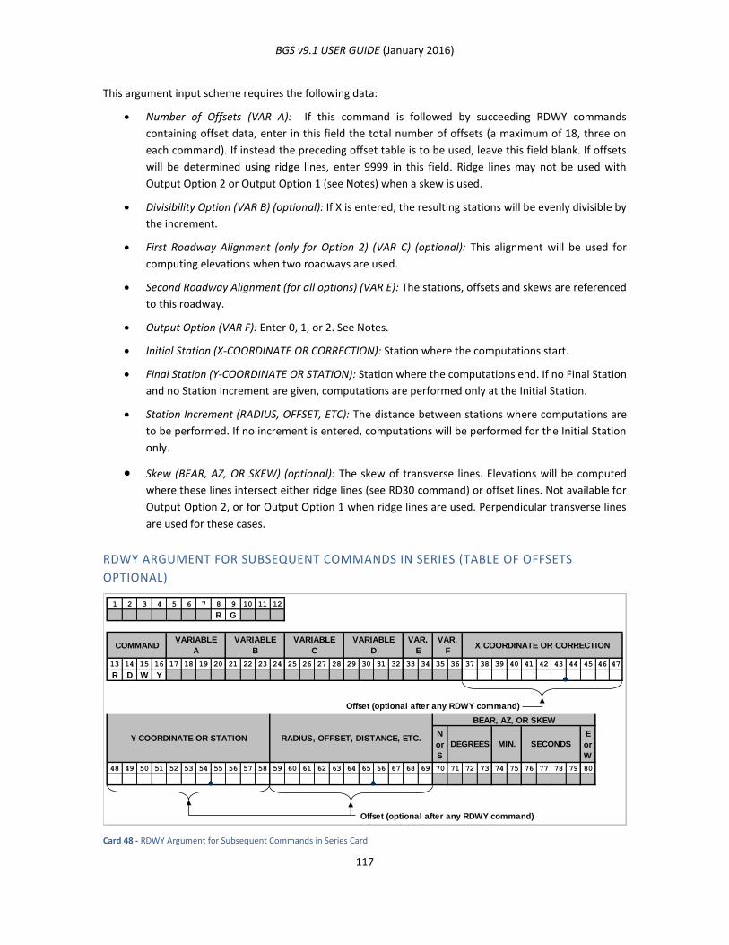
BGS v9.1 USER GUIDE (January 2016)
117
This argument input scheme requires the following data:
Number of Offsets (VAR A): If this command is followed by succeeding RDWY commands
containing offset data, enter in this field the total number of offsets (a maximum of 18, three on
each command). If instead the preceding offset table is to be used, leave this field blank. If offsets
will be determined using ridge lines, enter 9999 in this field. Ridge lines may not be used with
Output Option 2 or Output Option 1 (see Notes) when a skew is used.
Divisibility Option (VAR B) (optional): If X is entered, the resulting stations will be evenly divisible by
the increment.
First Roadway Alignment (only for Option 2) (VAR C) (optional): This alignment will be used for
computing elevations when two roadways are used.
Second Roadway Alignment (for all options) (VAR E): The stations, offsets and skews are referenced
to this roadway.
Output Option (VAR F): Enter 0, 1, or 2. See Notes.
Initial Station (X-COORDINATE OR CORRECTION): Station where the computations start.
Final Station (Y-COORDINATE OR STATION): Station where the computations end. If no Final Station
and no Station Increment are given, computations are performed only at the Initial Station.
Station Increment (RADIUS, OFFSET, ETC): The distance between stations where computations are
to be performed. If no increment is entered, computations will be performed for the Initial Station
only.
Skew (BEAR, AZ, OR SKEW) (optional): The skew of transverse lines. Elevations will be computed
where these lines intersect either ridge lines (see RD30 command) or offset lines. Not available for
Output Option 2, or for Output Option 1 when ridge lines are used. Perpendicular transverse lines
are used for these cases.
RDWY ARGUMENT FOR SUBSEQUENT COMMANDS IN SERIES (TABLE OF OFFSETS
OPTIONAL)
Card 48 - RDWY Argument for Subsequent Commands in Series Card
1 2 3 4 5 6 7 8 9 10 11 12
R G
13 14 15 16 17 18 19 20 21 22 23 24 25 26 27 28 29 30 31 32 33 34 35 36 37 38 39 40 41 42 43 44 45 46 47
R D W Y
Offset (optional after any RDWY command)
N
or
S
E
or
W
48 49 50 51 52 53 54 55 56 57 58 59 60 61 62 63 64 65 66 67 68 69 70 71 72 73 74 75 76 77 78 79 80
Offset (optional after any RDWY command)
VARIABLE
D
VAR.
E
VAR.
FX COORDINATE OR CORRECTIONCOMMAND
VARIABLE
A
VARIABLE
B
VARIABLE
C
RADIUS, OFFSET, DISTANCE, ETC.Y COORDINATE OR STATION
BEAR, AZ, OR SKEW
SECONDSMIN.DEGREES
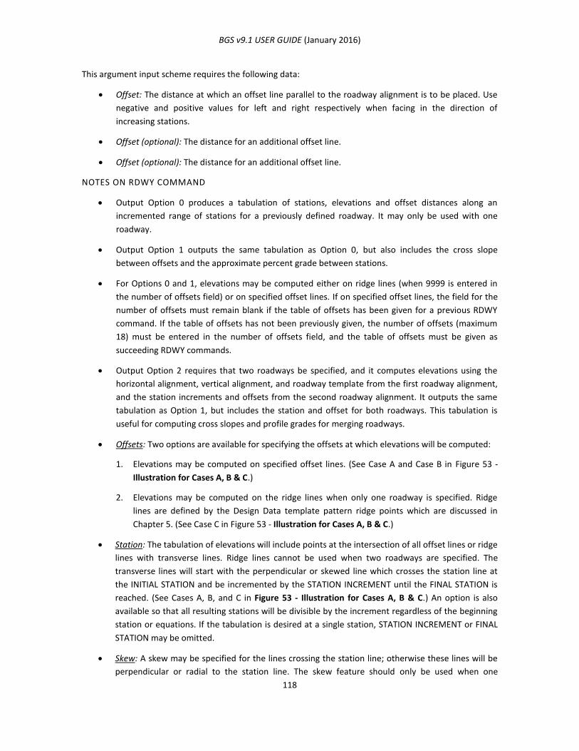
BGS v9.1 USER GUIDE (January 2016)
118
This argument input scheme requires the following data:
Offset: The distance at which an offset line parallel to the roadway alignment is to be placed. Use
negative and positive values for left and right respectively when facing in the direction of
increasing stations.
Offset (optional): The distance for an additional offset line.
Offset (optional): The distance for an additional offset line.
NOTES ON RDWY COMMAND
Output Option 0 produces a tabulation of stations, elevations and offset distances along an
incremented range of stations for a previously defined roadway. It may only be used with one
roadway.
Output Option 1 outputs the same tabulation as Option 0, but also includes the cross slope
between offsets and the approximate percent grade between stations.
For Options 0 and 1, elevations may be computed either on ridge lines (when 9999 is entered in
the number of offsets field) or on specified offset lines. If on specified offset lines, the field for the
number of offsets must remain blank if the table of offsets has been given for a previous RDWY
command. If the table of offsets has not been previously given, the number of offsets (maximum
18) must be entered in the number of offsets field, and the table of offsets must be given as
succeeding RDWY commands.
Output Option 2 requires that two roadways be specified, and it computes elevations using the
horizontal alignment, vertical alignment, and roadway template from the first roadway alignment,
and the station increments and offsets from the second roadway alignment. It outputs the same
tabulation as Option 1, but includes the station and offset for both roadways. This tabulation is
useful for computing cross slopes and profile grades for merging roadways.
Offsets: Two options are available for specifying the offsets at which elevations will be computed:
1. Elevations may be computed on specified offset lines. (See Case A and Case B in Figure 53 -
Illustration for Cases A, B & C.)
2. Elevations may be computed on the ridge lines when only one roadway is specified. Ridge
lines are defined by the Design Data template pattern ridge points which are discussed in
Chapter 5. (See Case C in Figure 53 - Illustration for Cases A, B & C.)
Station: The tabulation of elevations will include points at the intersection of all offset lines or ridge
lines with transverse lines. Ridge lines cannot be used when two roadways are specified. The
transverse lines will start with the perpendicular or skewed line which crosses the station line at
the INITIAL STATION and be incremented by the STATION INCREMENT until the FINAL STATION is
reached. (See Cases A, B, and C in Figure 53 - Illustration for Cases A, B & C.) An option is also
available so that all resulting stations will be divisible by the increment regardless of the beginning
station or equations. If the tabulation is desired at a single station, STATION INCREMENT or FINAL
STATION may be omitted.
Skew: A skew may be specified for the lines crossing the station line; otherwise these lines will be
perpendicular or radial to the station line. The skew feature should only be used when one
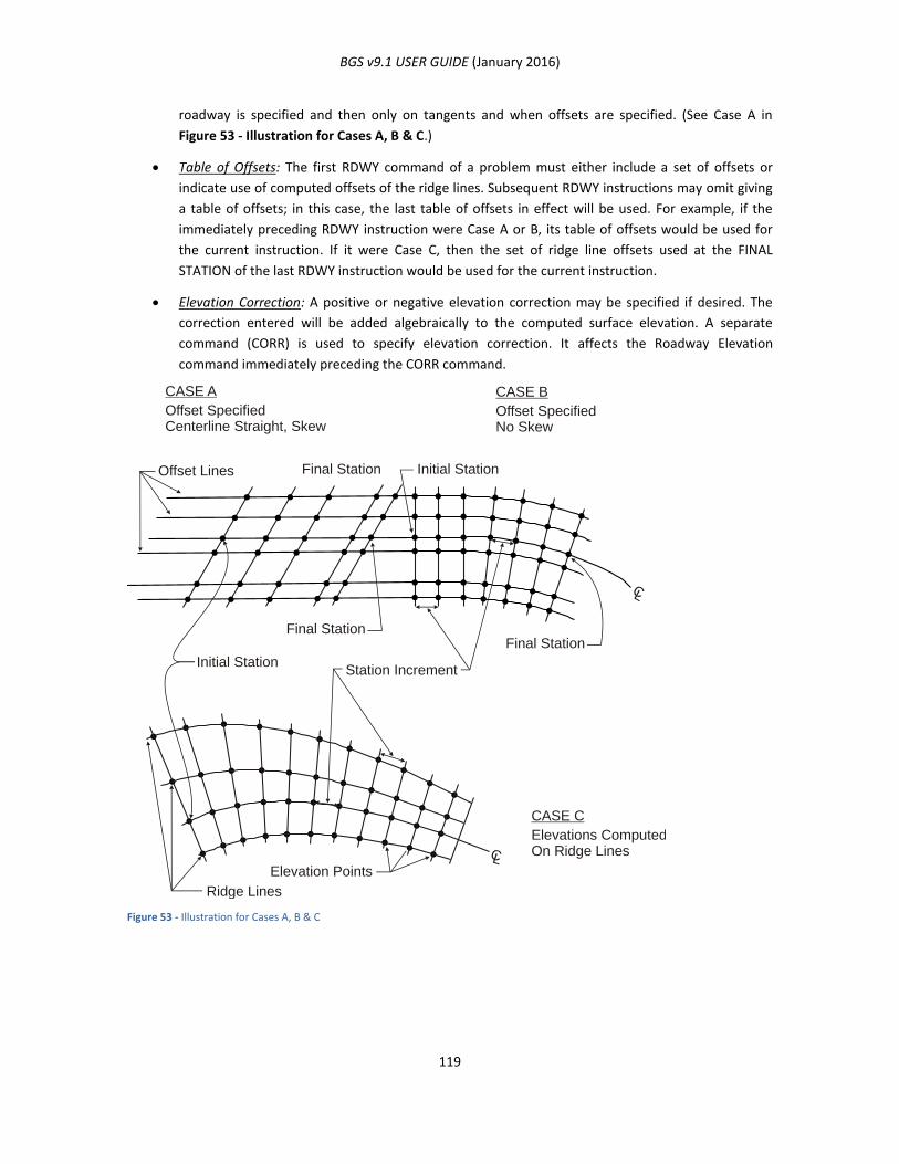
BGS v9.1 USER GUIDE (January 2016)
119
roadway is specified and then only on tangents and when offsets are specified. (See Case A in
Figure 53 - Illustration for Cases A, B & C.)
Table of Offsets: The first RDWY command of a problem must either include a set of offsets or
indicate use of computed offsets of the ridge lines. Subsequent RDWY instructions may omit giving
a table of offsets; in this case, the last table of offsets in effect will be used. For example, if the
immediately preceding RDWY instruction were Case A or B, its table of offsets would be used for
the current instruction. If it were Case C, then the set of ridge line offsets used at the FINAL
STATION of the last RDWY instruction would be used for the current instruction.
Elevation Correction: A positive or negative elevation correction may be specified if desired. The
correction entered will be added algebraically to the computed surface elevation. A separate
command (CORR) is used to specify elevation correction. It affects the Roadway Elevation
command immediately preceding the CORR command.
Figure 53 - Illustration for Cases A, B & C
CASE A
Offset Lines
Ridge Lines
Elevation Points
Final Station
Final StationFinal Station
Station Increment
Initial Station
Initial Station
CASE B
CASE C
Offset SpecifiedCenterline Straight, Skew
Offset SpecifiedNo Skew
Elevations ComputedOn Ridge LinesCL
CL
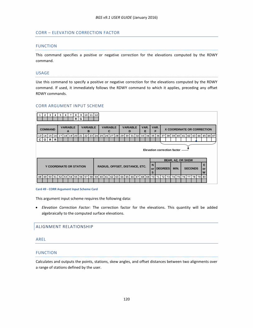
BGS v9.1 USER GUIDE (January 2016)
120
CORR – ELEVATION CORRECTION FACTOR
FUNCTION
This command specifies a positive or negative correction for the elevations computed by the RDWY
command.
USAGE
Use this command to specify a positive or negative correction for the elevations computed by the RDWY
command. If used, it immediately follows the RDWY command to which it applies, preceding any offset
RDWY commands.
CORR ARGUMENT INPUT SCHEME
Card 49 - CORR Argument Input Scheme Card
This argument input scheme requires the following data:
Elevation Correction Factor: The correction factor for the elevations. This quantity will be added
algebraically to the computed surface elevations.
ALIGNMENT RELATIONSHIP
AREL
FUNCTION
Calculates and outputs the points, stations, skew angles, and offset distances between two alignments over
a range of stations defined by the user.
1 2 3 4 5 6 7 8 9 10 11 12
R G
13 14 15 16 17 18 19 20 21 22 23 24 25 26 27 28 29 30 31 32 33 34 35 36 37 38 39 40 41 42 43 44 45 46 47
C O R R
Elevation correction factor
N
or
S
E
or
W
48 49 50 51 52 53 54 55 56 57 58 59 60 61 62 63 64 65 66 67 68 69 70 71 72 73 74 75 76 77 78 79 80
X COORDINATE OR CORRECTION
BEAR, AZ, OR SKEW
SECONDSMIN.DEGREESRADIUS, OFFSET, DISTANCE, ETC.Y COORDINATE OR STATION
VAR.
FCOMMAND
VARIABLE
A
VARIABLE
B
VARIABLE
C
VARIABLE
D
VAR.
E
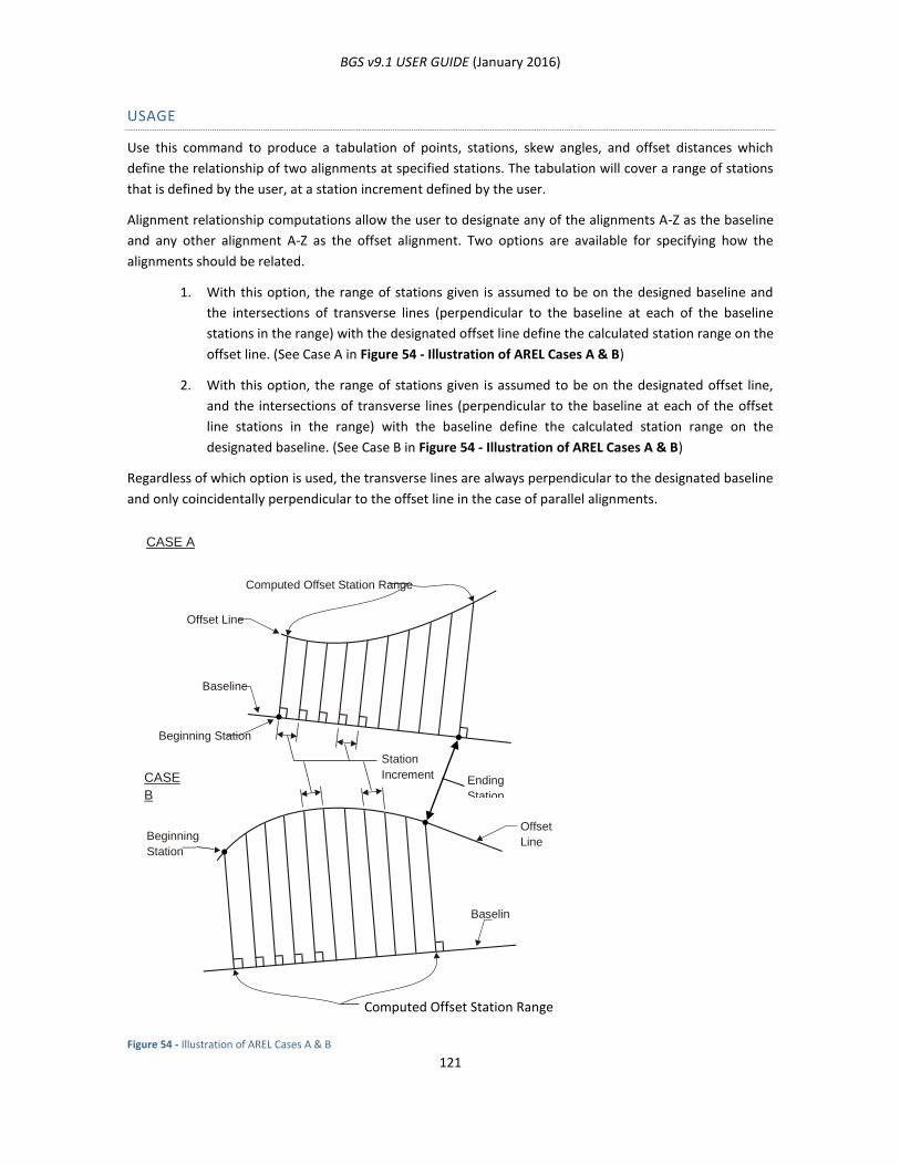
BGS v9.1 USER GUIDE (January 2016)
121
USAGE
Use this command to produce a tabulation of points, stations, skew angles, and offset distances which
define the relationship of two alignments at specified stations. The tabulation will cover a range of stations
that is defined by the user, at a station increment defined by the user.
Alignment relationship computations allow the user to designate any of the alignments A-Z as the baseline
and any other alignment A-Z as the offset alignment. Two options are available for specifying how the
alignments should be related.
1. With this option, the range of stations given is assumed to be on the designed baseline and
the intersections of transverse lines (perpendicular to the baseline at each of the baseline
stations in the range) with the designated offset line define the calculated station range on the
offset line. (See Case A in Figure 54 - Illustration of AREL Cases A & B)
2. With this option, the range of stations given is assumed to be on the designated offset line,
and the intersections of transverse lines (perpendicular to the baseline at each of the offset
line stations in the range) with the baseline define the calculated station range on the
designated baseline. (See Case B in Figure 54 - Illustration of AREL Cases A & B)
Regardless of which option is used, the transverse lines are always perpendicular to the designated baseline
and only coincidentally perpendicular to the offset line in the case of parallel alignments.
Figure 54 - Illustration of AREL Cases A & B
CASE A
CASE
B
Beginning Station
Beginning
Station
Baseline
Baselin
e
Offset Line
Offset
Line
Computed Offset Station Range
Ending
Station
Station
Increment
Computed Offset Station Range

BGS v9.1 USER GUIDE (January 2016)
122
AREL ARGUMENT INPUT SCHEME
Card 50 - AREL Argument Input Scheme Card
This argument input scheme requires the following data:
Offset Alignment (VAR A): The alignment to be used as the offset line. If the baseline and the offset
alignments are the same, a station and coordinate list will be generated along the designated
alignment.
Divisibility Option (VAR B) (optional): If X is entered, the resulting stations will be evenly divisible by
the increment.
Baseline Alignment (VAR E): The alignment to be used as the baseline. Transverse lines used to
define the relation between the two alignments are perpendicular to the baseline.
Station Option (VAR F): If left blank, the station range indicated in the Initial Station and Final
Station fields is assumed to be on the baseline. (See Case A in the Figure 54 - Illustration of AREL
Cases A & B.) If X is entered, the station range indicated in the Initial Station and Final Station fields
is assumed to be on the offset alignment. (See Case B in Figure 54 - Illustration of AREL Cases A &
B.)
Initial Station (X-COORDINATE OR CORRECTION): Station where the computations start.
Final Station (Y-COORDINATE OR STATION): Station where the computations end. If no Final Station
and no Station Increment are given, an alignment relation is performed only at the Initial Station.
Station Increment (RADIUS, OFFSET, ETC) (optional): The distance between the stations where
computations are to be performed. If no increment is entered, an increment of 100 is used.
1 2 3 4 5 6 7 8 9 10 11 12
R G
13 14 15 16 17 18 19 20 21 22 23 24 25 26 27 28 29 30 31 32 33 34 35 36 37 38 39 40 41 42 43 44 45 46 47
A R E L
Alignment (H-Z)
to be used as
offset.
Alignment (H-Z) to be used
as baselineInitial station
Optional, enter X for resulting
stations to be divisible by the
increment.
Station option (blank or X)
N
or
S
E
or
W
48 49 50 51 52 53 54 55 56 57 58 59 60 61 62 63 64 65 66 67 68 69 70 71 72 73 74 75 76 77 78 79 80
Final station Station increment
VARIABLE
C
VARIABLE
B
VARIABLE
ACOMMAND X COORDINATE OR CORRECTION
VAR.
F
VAR.
E
VARIABLE
D
SECONDS
BEAR, AZ, OR SKEW
Y COORDINATE OR STATION RADIUS, OFFSET, DISTANCE, ETC.DEGREES MIN.
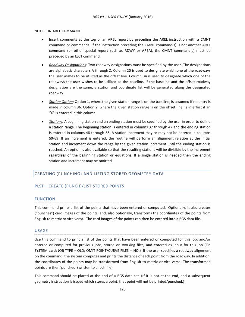
BGS v9.1 USER GUIDE (January 2016)
123
NOTES ON AREL COMMAND
Insert comments at the top of an AREL report by preceding the AREL instruction with a CMNT
command or commands. If the instruction preceding the CMNT command(s) is not another AREL
command (or other special report such as RDWY or AREA), the CMNT command(s) must be
preceded by an EJCT command.
Roadway Designations: Two roadway designations must be specified by the user. The designations
are alphabetic characters A through Z. Column 20 is used to designate which one of the roadways
the user wishes to be utilized as the offset line. Column 34 is used to designate which one of the
roadways the user wishes to be utilized as the baseline. If the baseline and the offset roadway
designation are the same, a station and coordinate list will be generated along the designated
roadway.
Station Option: Option 1, where the given station range is on the baseline, is assumed if no entry is
made in column 36. Option 2, where the given station range is on the offset line, is in effect if an
“X” is entered in this column.
Stations: A beginning station and an ending station must be specified by the user in order to define
a station range. The beginning station is entered in columns 37 through 47 and the ending station
is entered in columns 48 through 58. A station increment may or may not be entered in columns
59-69. If an increment is entered, the routine will perform an alignment relation at the initial
station and increment down the range by the given station increment until the ending station is
reached. An option is also available so that the resulting stations will be divisible by the increment
regardless of the beginning station or equations. If a single station is needed then the ending
station and increment may be omitted.
CREATING (PUNCHING) AND LISTING STORED GEOMETRY DATA
PLST – CREATE (PUNCH)/LIST STORED POINTS
FUNCTION
This command prints a list of the points that have been entered or computed. Optionally, it also creates
(“punches”) card images of the points, and, also optionally, transforms the coordinates of the points from
English to metric or vice versa. The card images of the points can then be entered into a BGS data file.
USAGE
Use this command to print a list of the points that have been entered or computed for this job, and/or
entered or computed for previous jobs, stored on working files, and entered as input for this job (On
SYSTEM card: JOB TYPE = OLD; OMIT POINT/CURVE FILES -- NO.) If the user specifies a roadway alignment
on the command, the system computes and prints the distance of each point from the roadway. In addition,
the coordinates of the points may be transformed from English to metric or vice versa. The transformed
points are then 'punched' (written to a .pch file).
This command should be placed at the end of a BGS data set. (If it is not at the end, and a subsequent
geometry instruction is issued which stores a point, that point will not be printed/punched.)
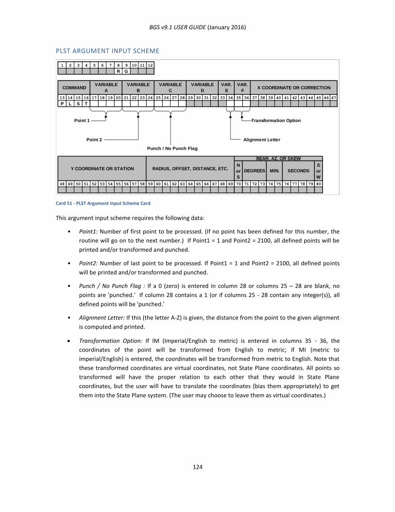
BGS v9.1 USER GUIDE (January 2016)
124
PLST ARGUMENT INPUT SCHEME
Card 51 - PLST Argument Input Scheme Card
This argument input scheme requires the following data:
• Point1: Number of first point to be processed. (If no point has been defined for this number, the
routine will go on to the next number.) If Point1 = 1 and Point2 = 2100, all defined points will be
printed and/or transformed and punched.
• Point2: Number of last point to be processed. If Point1 = 1 and Point2 = 2100, all defined points
will be printed and/or transformed and punched.
• Punch / No Punch Flag : If a 0 (zero) is entered in column 28 or columns 25 – 28 are blank, no
points are 'punched.' If column 28 contains a 1 (or if columns 25 - 28 contain any integer(s)), all
defined points will be 'punched.'
• Alignment Letter: If this (the letter A-Z) is given, the distance from the point to the given alignment
is computed and printed.
Transformation Option: If IM (Imperial/English to metric) is entered in columns 35 - 36, the
coordinates of the point will be transformed from English to metric; if MI (metric to
imperial/English) is entered, the coordinates will be transformed from metric to English. Note that
these transformed coordinates are virtual coordinates, not State Plane coordinates. All points so
transformed will have the proper relation to each other that they would in State Plane
coordinates, but the user will have to translate the coordinates (bias them appropriately) to get
them into the State Plane system. (The user may choose to leave them as virtual coordinates.)
1 2 3 4 5 6 7 8 9 10 11 12
R G
13 14 15 16 17 18 19 20 21 22 23 24 25 26 27 28 29 30 31 32 33 34 35 36 37 38 39 40 41 42 43 44 45 46 47
P L S T
Point 1 Transformation Option
Alignment Letter
Punch / No Punch Flag
N
or
S
E
or
W
48 49 50 51 52 53 54 55 56 57 58 59 60 61 62 63 64 65 66 67 68 69 70 71 72 73 74 75 76 77 78 79 80
Point 2
Y COORDINATE OR STATION RADIUS, OFFSET, DISTANCE, ETC.
BEAR, AZ, OR SKEW
MIN.DEGREES SECONDS
VARIABLE
C
VARIABLE
B
VARIABLE
ACOMMAND X COORDINATE OR CORRECTION
VAR.
F
VAR.
E
VARIABLE
D
BGS v9.1 USER GUIDE (January 2016)
125
CLST – CREATE (PUNCH)/LIST STORED CURVES
FUNCTION
This command prints a list of the curves that have been entered or computed. Optionally, it also creates
(“punches”) card images of the curves, and, also optionally, transforms the coordinates of the curves from
English to metric or vice versa. The card images of the curves can then be entered into a BGS data file.
USAGE
Use this command to print a list of the curves that have been entered or computed for this job, and/or
entered or computed for previous jobs, stored on working files, and entered as input for this job (On
SYSTEM card: JOB TYPE = OLD; OMIT POINT/CURVE FILES -- NO.) In addition, the coordinates and, for
circular arcs, radii of the curves may be transformed from English to metric or vice versa. The transformed
curves are then 'punched' (written to a .pch file).
This command should be placed at the end of a BGS data set. (If it is not at the end, and a subsequent
geometry instruction is issued which stores a curve, that curve will not be printed/punched.)
CLST ARGUMENT INPUT SCHEME
Card 52 - CLST Argument Input Scheme Card
This argument input scheme requires the following data:
Curve1: Number of first curve to be processed. (If no curve has been defined for this number, the
routine will go on to the next number.) If Curve1 = 1 and Curve2 = 1400, all defined curves will be
printed and/or transformed and punched. Curve2: Number of last curve to be processed. If Curve1
= 1 and Curve2 = 1400, all defined curves will be printed and/or transformed and punched.
1 2 3 4 5 6 7 8 9 10 11 12
R G
13 14 15 16 17 18 19 20 21 22 23 24 25 26 27 28 29 30 31 32 33 34 35 36 37 38 39 40 41 42 43 44 45 46 47
C L S T
Curve 1 Transformation Option
Punch / No Punch Flag
N
or
S
E
or
W
48 49 50 51 52 53 54 55 56 57 58 59 60 61 62 63 64 65 66 67 68 69 70 71 72 73 74 75 76 77 78 79 80
VARIABLE
ACOMMAND X COORDINATE OR CORRECTION
VAR.
F
VAR.
E
VARIABLE
D
VARIABLE
C
VARIABLE
B
Curve 2
Y COORDINATE OR STATION RADIUS, OFFSET, DISTANCE, ETC.
BEAR, AZ, OR SKEW
MIN.DEGREES SECONDS

BGS v9.1 USER GUIDE (January 2016)
126
Punch / No Punch Flag: If a 0 (zero) is entered in column 28 or columns 25 – 28 are blank, no curves
are ‘punched.’ If column 28 contains a 1 (or if columns 25 – 28 contain any integer(s)), all defined
curves will be ‘punched.’
Transformation Option: If IM (imperial/English to metric) is entered in columns 35 - 36, the
coordinates of the feature and the radius (if the feature is a circular arc) will be transformed from
English to metric; if MI (metric to imperial/English) is entered, the coordinates and the radius will
be transformed from metric to English. Note that these transformed coordinates are virtual
coordinates, not State Plane coordinates. All features so transformed will have the proper relation
to each other that they would in State Plane coordinates, but the user will have to translate the
coordinates (bias them appropriately) to get them into the State Plane system. (The user may
choose to leave them as virtual coordinates.)
BGPN – TRANSFORM COMMAND UNITS AND PUNCH
FUNCTION
This command duplicates geometry and bridge geometry commands, with the coordinates, station
numbers, offsets, etc., transformed from English to metric or vice versa. These commands are then
“punched” as card images, which can then be entered into a BGS data file.
USAGE
Use this command to duplicate geometry and bridge geometry commands, with the coordinates, station
numbers, offsets, etc., transformed from English to metric or vice versa. The commands are then 'punched'
(written to a .pch file). The BGPN command asks for a station both in original units and in transformed
units. This permits the user to control the stationing in the transformed output. This command must be
placed in the BGS data set JUST BEFORE the data that is to be transformed.
BGPN ARGUMENT INPUT SCHEME
Card 53 - BGPN Argument Input Scheme Card
1 2 3 4 5 6 7 8 9 10 11 12
R G
13 14 15 16 17 18 19 20 21 22 23 24 25 26 27 28 29 30 31 32 33 34 35 36 37 38 39 40 41 42 43 44 45 46 47
B G P N
Transformation Option
Transformation Beginning Station, Original Units
N
or
S
E
or
W
48 49 50 51 52 53 54 55 56 57 58 59 60 61 62 63 64 65 66 67 68 69 70 71 72 73 74 75 76 77 78 79 80
Transformation Beginning Station, Transformed Units
Y COORDINATE OR STATION RADIUS, OFFSET, DISTANCE, ETC.
BEAR, AZ, OR SKEW
MIN.DEGREES SECONDS
VARIABLE
C
VARIABLE
B
VARIABLE
ACOMMAND X COORDINATE OR CORRECTION
VAR.
F
VAR.
E
VARIABLE
D

BGS v9.1 USER GUIDE (January 2016)
127
This argument input scheme requires the following data:
Transformation Option: If IM (imperial/English to metric) is entered in columns 35 - 36, all
distances in the command (coordinates, station numbers, offsets, etc.) will be transformed from
English to metric; if MI (metric to imperial/English) is entered, all distances will be transformed
from metric to English. Note that these transformed coordinates are virtual coordinates, not State
Plane. All coordinates so transformed will have the proper relation to each other that they would
in State Plane coordinates, but the user will have to translate the coordinates (bias them
appropriately) to get them into the State Plane system. (The user may choose to leave them as
virtual coordinates.)
Transformation Beginning Station, Original Units: For an English-to-metric transformation, this is
the beginning station in feet. For a metric-to-English transformation, this is the beginning station in
meters. The field has four assumed decimal places, as elsewhere in BGS.
Transformation Beginning Station, Transformed Units: For an English-to-metric transformation, this
is the beginning station in meters. For a metric-to-English transformation, this is the beginning
station in feet. The field has four assumed decimal places, as elsewhere in BGS.
BGS v9.1 USER GUIDE (January 2016)
128
CHAPTER 7: COMMAND STRUCTURED INPUT – BRIDGE GEOMETRY
BRIDGE GEOMETRY COMMANDS
INTRODUCTION
Bridge geometry commands empower the user to:
Define the plan view elements of structures.
Compute the dimensional aspects of the bridge frame and slab.
Compute the vertical and horizontal blocking data for continuous beams.
Plot the plan view of the structure.
Compute bridge construction grades.
Compute vertical clearance between structures and lower roadways or between the top of a
roadway’s beams and its own bottom of slab.
These operations are performed by using the bridge commands in sequence. A typical sequence is listed
below with an annotated explanation of the function of each command.
NAME (name) – establishes a file for storing each structure’s data. The Bridge alignment and stationing are
identified along with the size, type and loading.
PSLB (parallel slab line) – defines lines that are the outside edges of the slab and slab break lines.
TSLB (transverse slab line) – defines straight lines which are used to locate the ends of the slab.
SLAB (slab) – intersects two PSLB lines with two TSLB or Bent Lines to define the boundaries of the slab and
plots the slab (optional). It also defines the interior and overhang slab depths.
SLEL (slab elevations) – produces a tabulation of surface elevations and bottom of slab elevations along the
boundaries of the slab.
BENT (bent line) – defines straight lines which represent the centerline of bents or other supporting
members for the structure.
BRNG (bearing seat) – locates the bearing seats and beam ends relative to the Bent Lines.
DIAF (diaphragm line) – defines straight lines which indicate the location of diaphragm members between
beams.
SPLC (splice line) – defines straight lines which indicate the location of beam splices in continuous units.
BEAM (beam line) – defines Beam Lines which are used in various ways to locate actual beams in the
structure.
BGRP (beam line group) – defines groups of parallel or concentric Beam Lines.
FOPT (frame option) – requests computation of the bridge frame layout. This command intersects Bent and
Splice Lines with Beam Lines to define the actual location of the beams. Bearing seat locations and
diaphragm intersections are computer on chords between successive bents and splices. An option is
available for curved continuous beams. Various reports are generated along with an optional plan view plot.
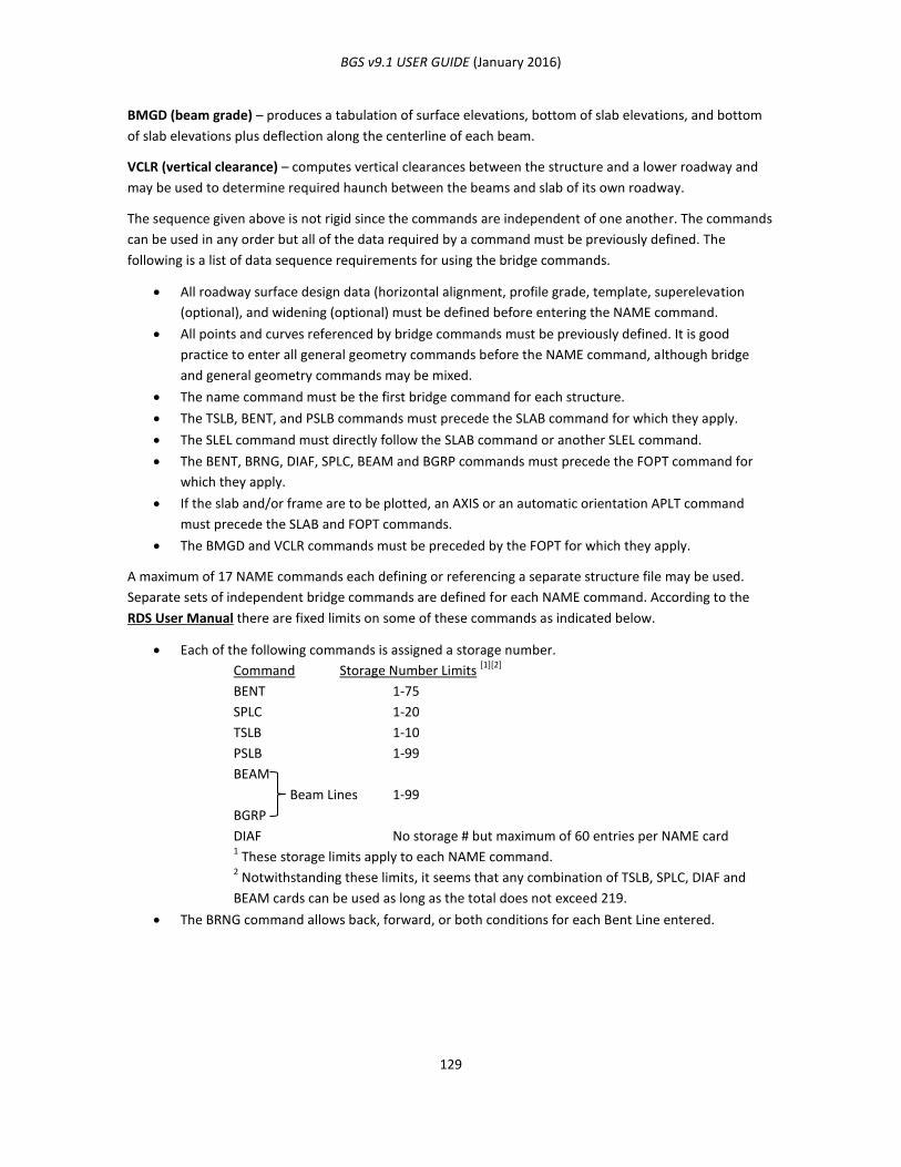
BGS v9.1 USER GUIDE (January 2016)
129
BMGD (beam grade) – produces a tabulation of surface elevations, bottom of slab elevations, and bottom
of slab elevations plus deflection along the centerline of each beam.
VCLR (vertical clearance) – computes vertical clearances between the structure and a lower roadway and
may be used to determine required haunch between the beams and slab of its own roadway.
The sequence given above is not rigid since the commands are independent of one another. The commands
can be used in any order but all of the data required by a command must be previously defined. The
following is a list of data sequence requirements for using the bridge commands.
All roadway surface design data (horizontal alignment, profile grade, template, superelevation
(optional), and widening (optional) must be defined before entering the NAME command.
All points and curves referenced by bridge commands must be previously defined. It is good
practice to enter all general geometry commands before the NAME command, although bridge
and general geometry commands may be mixed.
The name command must be the first bridge command for each structure.
The TSLB, BENT, and PSLB commands must precede the SLAB command for which they apply.
The SLEL command must directly follow the SLAB command or another SLEL command.
The BENT, BRNG, DIAF, SPLC, BEAM and BGRP commands must precede the FOPT command for
which they apply.
If the slab and/or frame are to be plotted, an AXIS or an automatic orientation APLT command
must precede the SLAB and FOPT commands.
The BMGD and VCLR commands must be preceded by the FOPT for which they apply.
A maximum of 17 NAME commands each defining or referencing a separate structure file may be used.
Separate sets of independent bridge commands are defined for each NAME command. According to the
RDS User Manual there are fixed limits on some of these commands as indicated below.
Each of the following commands is assigned a storage number.
Command Storage Number Limits [1][2]
BENT 1-75
SPLC 1-20
TSLB 1-10
PSLB 1-99
BEAM
Beam Lines 1-99
BGRP
DIAF No storage # but maximum of 60 entries per NAME card 1 These storage limits apply to each NAME command.
2 Notwithstanding these limits, it seems that any combination of TSLB, SPLC, DIAF and
BEAM cards can be used as long as the total does not exceed 219.
The BRNG command allows back, forward, or both conditions for each Bent Line entered.
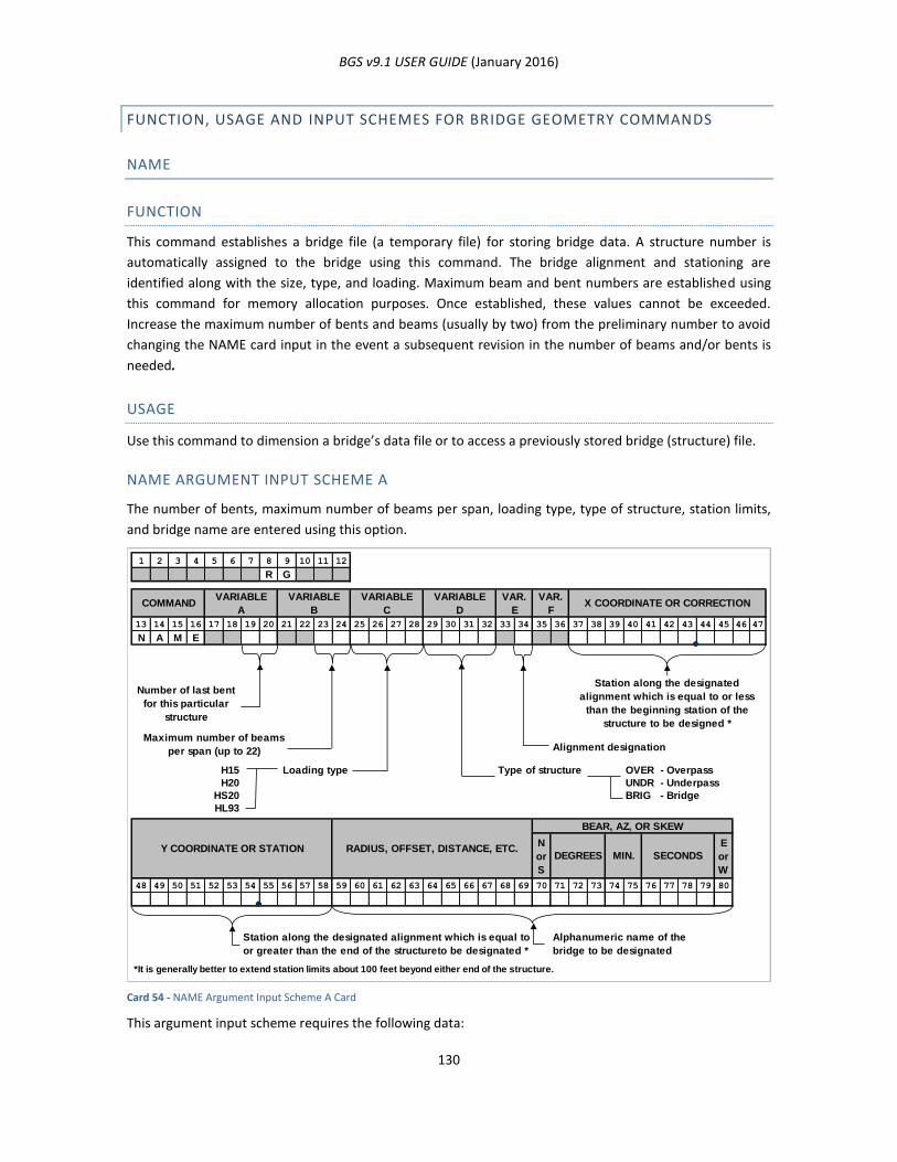
BGS v9.1 USER GUIDE (January 2016)
130
FUNCTION, USAGE AND INPUT SCHEMES FOR BRIDGE GEOMETRY COMMANDS
NAME
FUNCTION
This command establishes a bridge file (a temporary file) for storing bridge data. A structure number is
automatically assigned to the bridge using this command. The bridge alignment and stationing are
identified along with the size, type, and loading. Maximum beam and bent numbers are established using
this command for memory allocation purposes. Once established, these values cannot be exceeded.
Increase the maximum number of bents and beams (usually by two) from the preliminary number to avoid
changing the NAME card input in the event a subsequent revision in the number of beams and/or bents is
needed.
USAGE
Use this command to dimension a bridge’s data file or to access a previously stored bridge (structure) file.
NAME ARGUMENT INPUT SCHEME A
The number of bents, maximum number of beams per span, loading type, type of structure, station limits,
and bridge name are entered using this option.
Card 54 - NAME Argument Input Scheme A Card
This argument input scheme requires the following data:
1 2 3 4 5 6 7 8 9 10 11 12
R G
13 14 15 16 17 18 19 20 21 22 23 24 25 26 27 28 29 30 31 32 33 34 35 36 37 38 39 40 41 42 43 44 45 46 47
N A M E
Number of last bent
for this particular
structure
Station along the designated
alignment which is equal to or less
than the beginning station of the
structure to be designed *
Maximum number of beams
per span (up to 22) Alignment designation
H15 Loading type Type of structure OVER - Overpass
H20 UNDR - Underpass
HS20 BRIG - Bridge
HL93
N
or
S
E
or
W
48 49 50 51 52 53 54 55 56 57 58 59 60 61 62 63 64 65 66 67 68 69 70 71 72 73 74 75 76 77 78 79 80
*It is generally better to extend station limits about 100 feet beyond either end of the structure.
RADIUS, OFFSET, DISTANCE, ETC.
Alphanumeric name of the
bridge to be designated
Station along the designated alignment which is equal to
or greater than the end of the structureto be designated *
VARIABLE
ACOMMAND
SECONDS
X COORDINATE OR CORRECTIONVAR.
F
VAR.
E
VARIABLE
D
VARIABLE
C
VARIABLE
B
Y COORDINATE OR STATIONMIN.DEGREES
BEAR, AZ, OR SKEW
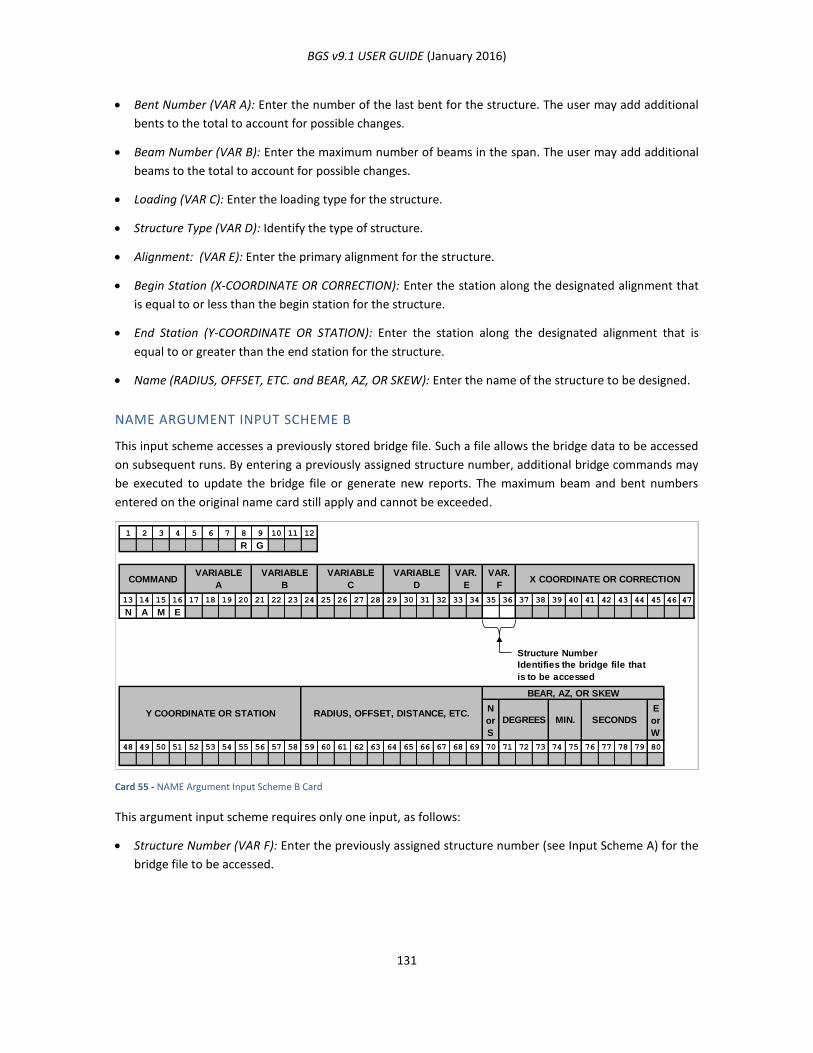
BGS v9.1 USER GUIDE (January 2016)
131
Bent Number (VAR A): Enter the number of the last bent for the structure. The user may add additional
bents to the total to account for possible changes.
Beam Number (VAR B): Enter the maximum number of beams in the span. The user may add additional
beams to the total to account for possible changes.
Loading (VAR C): Enter the loading type for the structure.
Structure Type (VAR D): Identify the type of structure.
Alignment: (VAR E): Enter the primary alignment for the structure.
Begin Station (X-COORDINATE OR CORRECTION): Enter the station along the designated alignment that
is equal to or less than the begin station for the structure.
End Station (Y-COORDINATE OR STATION): Enter the station along the designated alignment that is
equal to or greater than the end station for the structure.
Name (RADIUS, OFFSET, ETC. and BEAR, AZ, OR SKEW): Enter the name of the structure to be designed.
NAME ARGUMENT INPUT SCHEME B
This input scheme accesses a previously stored bridge file. Such a file allows the bridge data to be accessed
on subsequent runs. By entering a previously assigned structure number, additional bridge commands may
be executed to update the bridge file or generate new reports. The maximum beam and bent numbers
entered on the original name card still apply and cannot be exceeded.
Card 55 - NAME Argument Input Scheme B Card
This argument input scheme requires only one input, as follows:
Structure Number (VAR F): Enter the previously assigned structure number (see Input Scheme A) for the
bridge file to be accessed.
1 2 3 4 5 6 7 8 9 10 11 12
R G
13 14 15 16 17 18 19 20 21 22 23 24 25 26 27 28 29 30 31 32 33 34 35 36 37 38 39 40 41 42 43 44 45 46 47
N A M E
Structure Number
N
or
S
E
or
W
48 49 50 51 52 53 54 55 56 57 58 59 60 61 62 63 64 65 66 67 68 69 70 71 72 73 74 75 76 77 78 79 80
VARIABLE
A
Identifies the bridge file that
is to be accessed
X COORDINATE OR CORRECTIONVAR.
F
VAR.
ECOMMAND
VARIABLE
D
VARIABLE
C
VARIABLE
B
SECONDSMIN.DEGREES
BEAR, AZ, OR SKEW
RADIUS, OFFSET, DISTANCE, ETC.Y COORDINATE OR STATION

BGS v9.1 USER GUIDE (January 2016)
132
PSLB (PARALLEL SLAB LINE)
FUNCTION
This command establishes a longitudinal line used to define slab edge boundaries and slab break lines.
Figure 55 - PSLB Lines
USAGE
Use this command to define longitudinal lines that represent the outside edges of the slab and slab break
lines. PSLB lines may consist of from one to thirty-four (34) straight line and/or circular elements. They are
limited in extent since their end points must be defined. PSLB lines are given a storage number between 1
and 99 for each structure. These numbers are used for reference by other commands. The user should be
aware of the direction of the PSLB line. See the argument input schemes for information regarding direction
of the PSLB lines. Lines may be defined by giving their offset from another PSLB line or from any stored
alignment. The direction of the PSLB line will be the same as the direction of the referenced PSLB line or
alignment.
PSLB ARGUMENT INPUT SCHEME A
This input scheme defines a PSLB line parallel to the bridge alignment. The centerline of the bridge between
the station limits specified using the NAME command is automatically stored. The PSLB line will have the
same direction as the referenced bridge alignment.
PSLB Lines define slab break line
PSLB Lines define outside
edge of slab
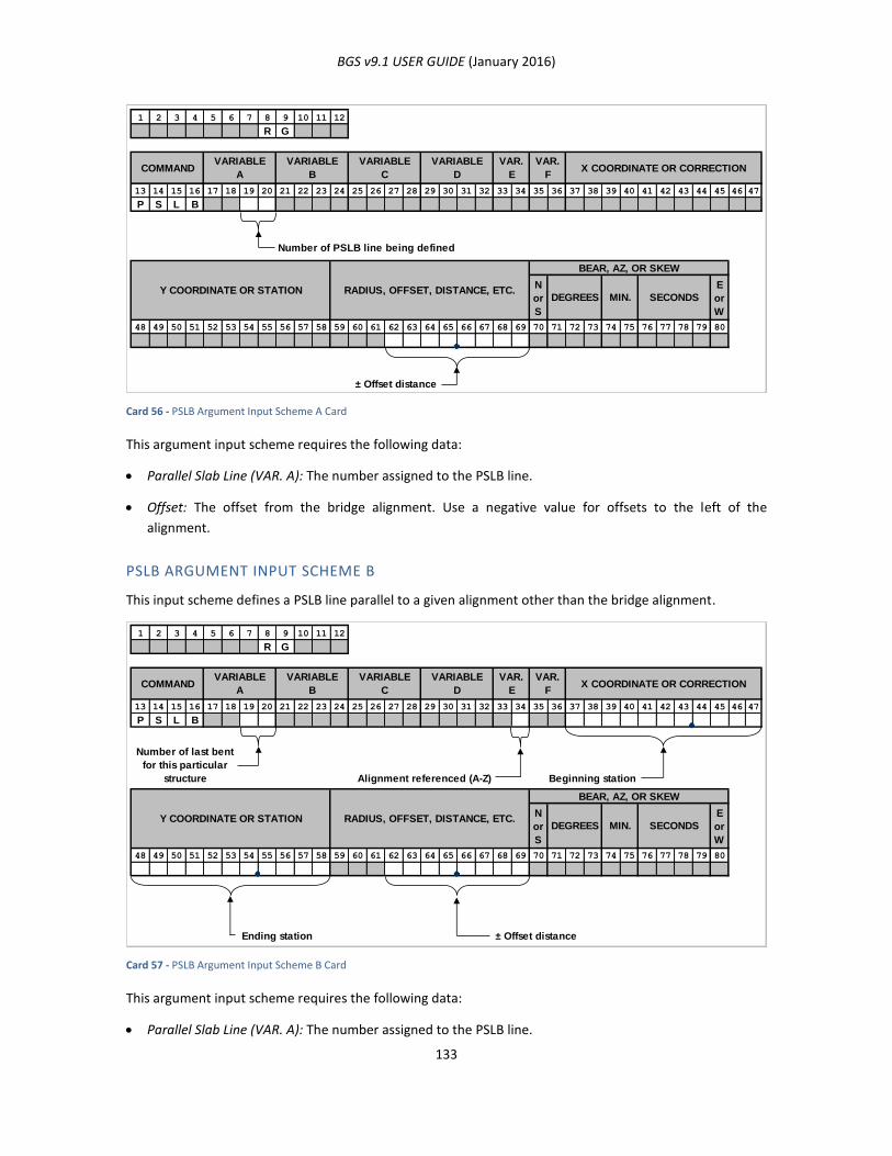
BGS v9.1 USER GUIDE (January 2016)
133
Card 56 - PSLB Argument Input Scheme A Card
This argument input scheme requires the following data:
Parallel Slab Line (VAR. A): The number assigned to the PSLB line.
Offset: The offset from the bridge alignment. Use a negative value for offsets to the left of the
alignment.
PSLB ARGUMENT INPUT SCHEME B
This input scheme defines a PSLB line parallel to a given alignment other than the bridge alignment.
Card 57 - PSLB Argument Input Scheme B Card
This argument input scheme requires the following data:
Parallel Slab Line (VAR. A): The number assigned to the PSLB line.
1 2 3 4 5 6 7 8 9 10 11 12
R G
13 14 15 16 17 18 19 20 21 22 23 24 25 26 27 28 29 30 31 32 33 34 35 36 37 38 39 40 41 42 43 44 45 46 47
P S L B
Number of PSLB line being defined
N
or
S
E
or
W
48 49 50 51 52 53 54 55 56 57 58 59 60 61 62 63 64 65 66 67 68 69 70 71 72 73 74 75 76 77 78 79 80
± Offset distance
RADIUS, OFFSET, DISTANCE, ETC.Y COORDINATE OR STATIONSECONDSMIN.DEGREES
BEAR, AZ, OR SKEW
VARIABLE
D
VAR.
E
VAR.
FX COORDINATE OR CORRECTIONCOMMAND
VARIABLE
A
VARIABLE
B
VARIABLE
C
1 2 3 4 5 6 7 8 9 10 11 12
R G
13 14 15 16 17 18 19 20 21 22 23 24 25 26 27 28 29 30 31 32 33 34 35 36 37 38 39 40 41 42 43 44 45 46 47
P S L B
Number of last bent
for this particular
structure Alignment referenced (A-Z) Beginning station
N
or
S
E
or
W
48 49 50 51 52 53 54 55 56 57 58 59 60 61 62 63 64 65 66 67 68 69 70 71 72 73 74 75 76 77 78 79 80
Ending station ± Offset distance
RADIUS, OFFSET, DISTANCE, ETC.Y COORDINATE OR STATION
VARIABLE
D
VARIABLE
CCOMMAND
VARIABLE
A
VARIABLE
B
VAR.
E
VAR.
FX COORDINATE OR CORRECTION
SECONDSMIN.
BEAR, AZ, OR SKEW
DEGREES
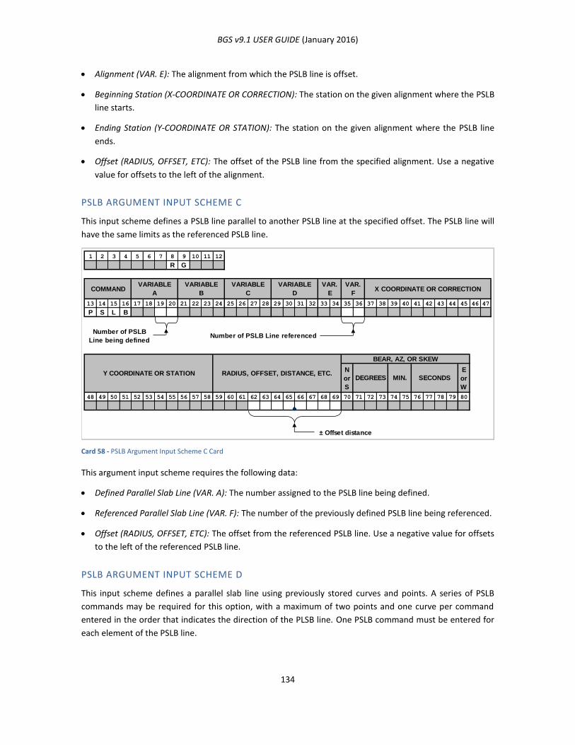
BGS v9.1 USER GUIDE (January 2016)
134
Alignment (VAR. E): The alignment from which the PSLB line is offset.
Beginning Station (X-COORDINATE OR CORRECTION): The station on the given alignment where the PSLB
line starts.
Ending Station (Y-COORDINATE OR STATION): The station on the given alignment where the PSLB line
ends.
Offset (RADIUS, OFFSET, ETC): The offset of the PSLB line from the specified alignment. Use a negative
value for offsets to the left of the alignment.
PSLB ARGUMENT INPUT SCHEME C
This input scheme defines a PSLB line parallel to another PSLB line at the specified offset. The PSLB line will
have the same limits as the referenced PSLB line.
Card 58 - PSLB Argument Input Scheme C Card
This argument input scheme requires the following data:
Defined Parallel Slab Line (VAR. A): The number assigned to the PSLB line being defined.
Referenced Parallel Slab Line (VAR. F): The number of the previously defined PSLB line being referenced.
Offset (RADIUS, OFFSET, ETC): The offset from the referenced PSLB line. Use a negative value for offsets
to the left of the referenced PSLB line.
PSLB ARGUMENT INPUT SCHEME D
This input scheme defines a parallel slab line using previously stored curves and points. A series of PSLB
commands may be required for this option, with a maximum of two points and one curve per command
entered in the order that indicates the direction of the PLSB line. One PSLB command must be entered for
each element of the PSLB line.
1 2 3 4 5 6 7 8 9 10 11 12
R G
13 14 15 16 17 18 19 20 21 22 23 24 25 26 27 28 29 30 31 32 33 34 35 36 37 38 39 40 41 42 43 44 45 46 47
P S L B
Number of PSLB
Line being definedNumber of PSLB Line referenced
N
or
S
E
or
W
48 49 50 51 52 53 54 55 56 57 58 59 60 61 62 63 64 65 66 67 68 69 70 71 72 73 74 75 76 77 78 79 80
± Offset distance
RADIUS, OFFSET, DISTANCE, ETC.Y COORDINATE OR STATIONSECONDSMIN.DEGREES
BEAR, AZ, OR SKEW
VARIABLE
C
VARIABLE
B
VARIABLE
ACOMMAND X COORDINATE OR CORRECTION
VAR.
F
VAR.
E
VARIABLE
D
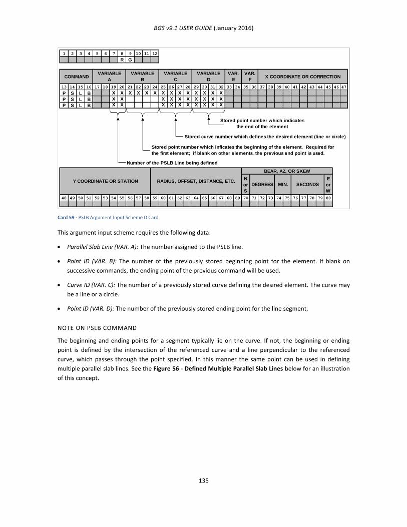
BGS v9.1 USER GUIDE (January 2016)
135
Card 59 - PSLB Argument Input Scheme D Card
This argument input scheme requires the following data:
Parallel Slab Line (VAR. A): The number assigned to the PSLB line.
Point ID (VAR. B): The number of the previously stored beginning point for the element. If blank on
successive commands, the ending point of the previous command will be used.
Curve ID (VAR. C): The number of a previously stored curve defining the desired element. The curve may
be a line or a circle.
Point ID (VAR. D): The number of the previously stored ending point for the line segment.
NOTE ON PSLB COMMAND
The beginning and ending points for a segment typically lie on the curve. If not, the beginning or ending
point is defined by the intersection of the referenced curve and a line perpendicular to the referenced
curve, which passes through the point specified. In this manner the same point can be used in defining
multiple parallel slab lines. See the Figure 56 - Defined Multiple Parallel Slab Lines below for an illustration
of this concept.
1 2 3 4 5 6 7 8 9 10 11 12
R G
13 14 15 16 17 18 19 20 21 22 23 24 25 26 27 28 29 30 31 32 33 34 35 36 37 38 39 40 41 42 43 44 45 46 47
P S L B X X X X X X X X X X X X X X
P S L B X X X X X X X X X X
P S L B X X X X X X X X X X
Stored point number which indicates
the end of the element
Stored curve number which defines the desired element (line or circle)
Number of the PSLB Line being defined
N
or
S
E
or
W
48 49 50 51 52 53 54 55 56 57 58 59 60 61 62 63 64 65 66 67 68 69 70 71 72 73 74 75 76 77 78 79 80
Stored point number which inficates the beginning of the element. Required for
the first element; if blank on other elements, the previous end point is used.
RADIUS, OFFSET, DISTANCE, ETC.Y COORDINATE OR STATIONSECONDSMIN.DEGREES
BEAR, AZ, OR SKEW
COMMANDVARIABLE
A
VARIABLE
B
VARIABLE
C
VARIABLE
D
VAR.
E
VAR.
FX COORDINATE OR CORRECTION
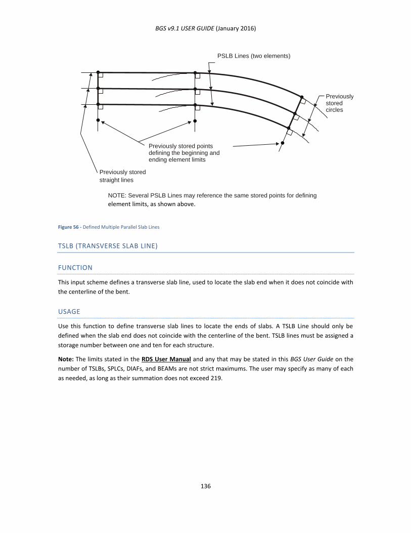
BGS v9.1 USER GUIDE (January 2016)
136
Figure 56 - Defined Multiple Parallel Slab Lines
TSLB (TRANSVERSE SLAB LINE)
FUNCTION
This input scheme defines a transverse slab line, used to locate the slab end when it does not coincide with
the centerline of the bent.
USAGE
Use this function to define transverse slab lines to locate the ends of slabs. A TSLB Line should only be
defined when the slab end does not coincide with the centerline of the bent. TSLB lines must be assigned a
storage number between one and ten for each structure.
Note: The limits stated in the RDS User Manual and any that may be stated in this BGS User Guide on the
number of TSLBs, SPLCs, DIAFs, and BEAMs are not strict maximums. The user may specify as many of each
as needed, as long as their summation does not exceed 219.
PSLB Lines (two elements)
NOTE: Several PSLB Lines may reference the same stored points for defining
element limits, as shown above.
Previously stored circles
Previously stored points defining the beginning and ending element limits
Previously stored
straight lines
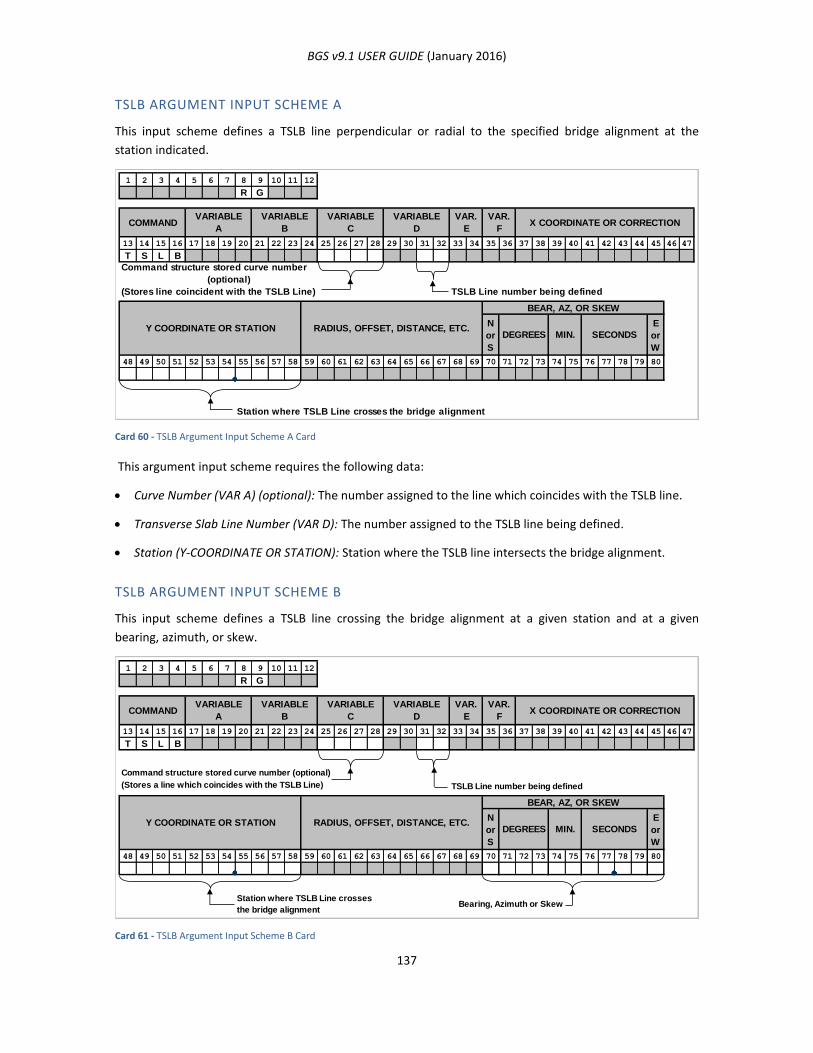
BGS v9.1 USER GUIDE (January 2016)
137
TSLB ARGUMENT INPUT SCHEME A
This input scheme defines a TSLB line perpendicular or radial to the specified bridge alignment at the
station indicated.
Card 60 - TSLB Argument Input Scheme A Card
This argument input scheme requires the following data:
Curve Number (VAR A) (optional): The number assigned to the line which coincides with the TSLB line.
Transverse Slab Line Number (VAR D): The number assigned to the TSLB line being defined.
Station (Y-COORDINATE OR STATION): Station where the TSLB line intersects the bridge alignment.
TSLB ARGUMENT INPUT SCHEME B
This input scheme defines a TSLB line crossing the bridge alignment at a given station and at a given
bearing, azimuth, or skew.
Card 61 - TSLB Argument Input Scheme B Card
1 2 3 4 5 6 7 8 9 10 11 12
R G
13 14 15 16 17 18 19 20 21 22 23 24 25 26 27 28 29 30 31 32 33 34 35 36 37 38 39 40 41 42 43 44 45 46 47
T S L B
TSLB Line number being defined
N
or
S
E
or
W
48 49 50 51 52 53 54 55 56 57 58 59 60 61 62 63 64 65 66 67 68 69 70 71 72 73 74 75 76 77 78 79 80
Station where TSLB Line crosses the bridge alignment
Command structure stored curve number
(optional)
(Stores line coincident with the TSLB Line)
VARIABLE
D
VAR.
E
VAR.
FX COORDINATE OR CORRECTIONCOMMAND
VARIABLE
A
VARIABLE
B
VARIABLE
C
RADIUS, OFFSET, DISTANCE, ETC.Y COORDINATE OR STATIONSECONDSMIN.DEGREES
BEAR, AZ, OR SKEW
1 2 3 4 5 6 7 8 9 10 11 12
R G
13 14 15 16 17 18 19 20 21 22 23 24 25 26 27 28 29 30 31 32 33 34 35 36 37 38 39 40 41 42 43 44 45 46 47
T S L B
Command structure stored curve number (optional)
(Stores a line which coincides with the TSLB Line) TSLB Line number being defined
N
or
S
E
or
W
48 49 50 51 52 53 54 55 56 57 58 59 60 61 62 63 64 65 66 67 68 69 70 71 72 73 74 75 76 77 78 79 80
Bearing, Azimuth or SkewStation where TSLB Line crosses
the bridge alignment
VARIABLE
A
SECONDSMIN.DEGREES
BEAR, AZ, OR SKEW
VARIABLE
D
VAR.
E
VAR.
FX COORDINATE OR CORRECTIONCOMMAND
VARIABLE
B
VARIABLE
C
RADIUS, OFFSET, DISTANCE, ETC.Y COORDINATE OR STATION
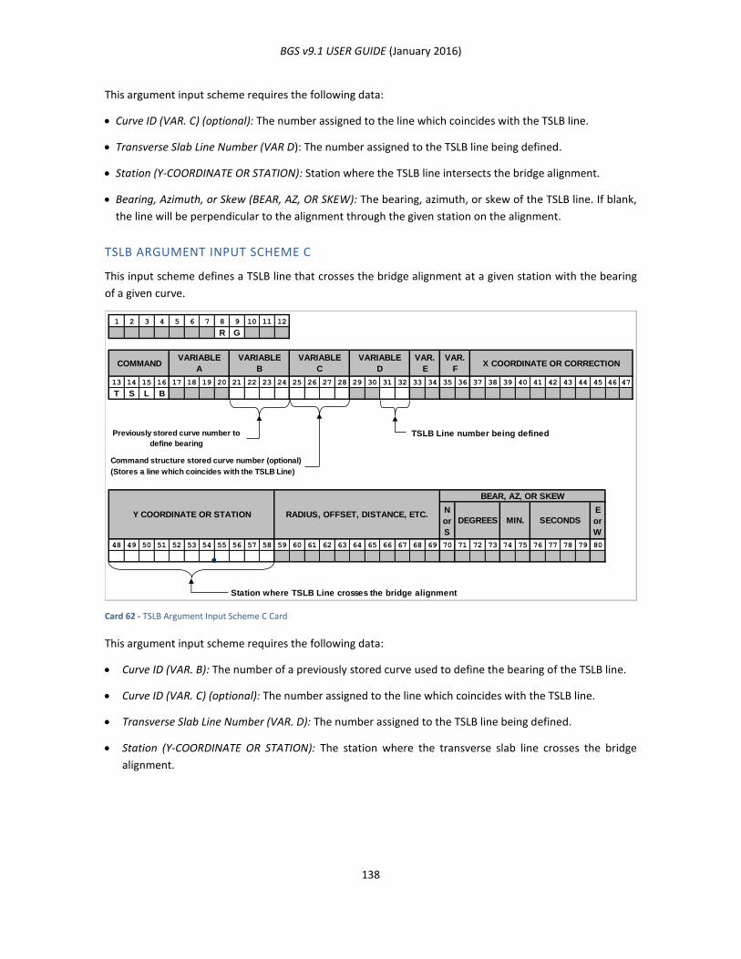
BGS v9.1 USER GUIDE (January 2016)
138
This argument input scheme requires the following data:
Curve ID (VAR. C) (optional): The number assigned to the line which coincides with the TSLB line.
Transverse Slab Line Number (VAR D): The number assigned to the TSLB line being defined.
Station (Y-COORDINATE OR STATION): Station where the TSLB line intersects the bridge alignment.
Bearing, Azimuth, or Skew (BEAR, AZ, OR SKEW): The bearing, azimuth, or skew of the TSLB line. If blank,
the line will be perpendicular to the alignment through the given station on the alignment.
TSLB ARGUMENT INPUT SCHEME C
This input scheme defines a TSLB line that crosses the bridge alignment at a given station with the bearing
of a given curve.
Card 62 - TSLB Argument Input Scheme C Card
This argument input scheme requires the following data:
Curve ID (VAR. B): The number of a previously stored curve used to define the bearing of the TSLB line.
Curve ID (VAR. C) (optional): The number assigned to the line which coincides with the TSLB line.
Transverse Slab Line Number (VAR. D): The number assigned to the TSLB line being defined.
Station (Y-COORDINATE OR STATION): The station where the transverse slab line crosses the bridge
alignment.
1 2 3 4 5 6 7 8 9 10 11 12
R G
13 14 15 16 17 18 19 20 21 22 23 24 25 26 27 28 29 30 31 32 33 34 35 36 37 38 39 40 41 42 43 44 45 46 47
T S L B
Previously stored curve number to
define bearing
TSLB Line number being defined
Command structure stored curve number (optional)
(Stores a line which coincides with the TSLB Line)
N
or
S
E
or
W
48 49 50 51 52 53 54 55 56 57 58 59 60 61 62 63 64 65 66 67 68 69 70 71 72 73 74 75 76 77 78 79 80
Station where TSLB Line crosses the bridge alignment
RADIUS, OFFSET, DISTANCE, ETC.Y COORDINATE OR STATIONSECONDSMIN.DEGREES
BEAR, AZ, OR SKEW
VARIABLE
C
VARIABLE
B
VARIABLE
ACOMMAND X COORDINATE OR CORRECTION
VAR.
F
VAR.
E
VARIABLE
D
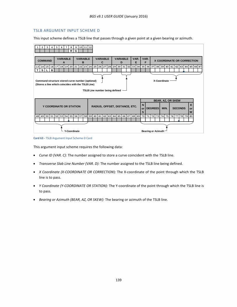
BGS v9.1 USER GUIDE (January 2016)
139
TSLB ARGUMENT INPUT SCHEME D
This input scheme defines a TSLB line that passes through a given point at a given bearing or azimuth.
Card 63 - TSLB Argument Input Scheme D Card
This argument input scheme requires the following data:
Curve ID (VAR. C): The number assigned to store a curve coincident with the TSLB line.
Transverse Slab Line Number (VAR. D): The number assigned to the TSLB line being defined.
X Coordinate (X-COORDINATE OR CORRECTION): The X-coordinate of the point through which the TSLB
line is to pass.
Y Coordinate (Y-COORDINATE OR STATION): The Y-coordinate of the point through which the TSLB line is
to pass.
Bearing or Azimuth (BEAR, AZ, OR SKEW): The bearing or azimuth of the TSLB line.
1 2 3 4 5 6 7 8 9 10 11 12
R G
13 14 15 16 17 18 19 20 21 22 23 24 25 26 27 28 29 30 31 32 33 34 35 36 37 38 39 40 41 42 43 44 45 46 47
T S L B
Command structure stored curve number (optional) X-Coordinate
(Stores a line which coincides with the TSLB Line)
TSLB Line number being defined
N
or
S
E
or
W
48 49 50 51 52 53 54 55 56 57 58 59 60 61 62 63 64 65 66 67 68 69 70 71 72 73 74 75 76 77 78 79 80
Y-Coordinate Bearing or Azimuth
VARIABLE
D
VAR.
E
VAR.
FX COORDINATE OR CORRECTIONCOMMAND
VARIABLE
A
VARIABLE
B
VARIABLE
C
Y COORDINATE OR STATION RADIUS, OFFSET, DISTANCE, ETC.
BEAR, AZ, OR SKEW
DEGREES MIN. SECONDS
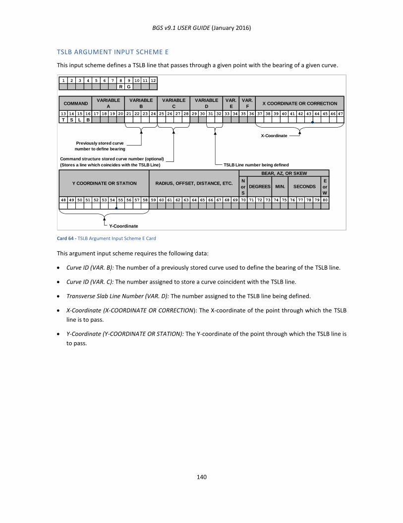
BGS v9.1 USER GUIDE (January 2016)
140
TSLB ARGUMENT INPUT SCHEME E
This input scheme defines a TSLB line that passes through a given point with the bearing of a given curve.
Card 64 - TSLB Argument Input Scheme E Card
This argument input scheme requires the following data:
Curve ID (VAR. B): The number of a previously stored curve used to define the bearing of the TSLB line.
Curve ID (VAR. C): The number assigned to store a curve coincident with the TSLB line.
Transverse Slab Line Number (VAR. D): The number assigned to the TSLB line being defined.
X-Coordinate (X-COORDINATE OR CORRECTION): The X-coordinate of the point through which the TSLB
line is to pass.
Y-Coordinate (Y-COORDINATE OR STATION): The Y-coordinate of the point through which the TSLB line is
to pass.
1 2 3 4 5 6 7 8 9 10 11 12
R G
13 14 15 16 17 18 19 20 21 22 23 24 25 26 27 28 29 30 31 32 33 34 35 36 37 38 39 40 41 42 43 44 45 46 47
T S L B
X-Coordinate
Previously stored curve
number to define bearing
Command structure stored curve number (optional)
(Stores a line which coincides with the TSLB Line) TSLB Line number being defined
N
or
S
E
or
W
48 49 50 51 52 53 54 55 56 57 58 59 60 61 62 63 64 65 66 67 68 69 70 71 72 73 74 75 76 77 78 79 80
Y-Coordinate
VARIABLE
D
VAR.
E
VAR.
FX COORDINATE OR CORRECTIONCOMMAND
VARIABLE
A
VARIABLE
B
VARIABLE
C
Y COORDINATE OR STATION RADIUS, OFFSET, DISTANCE, ETC.
BEAR, AZ, OR SKEW
DEGREES MIN. SECONDS
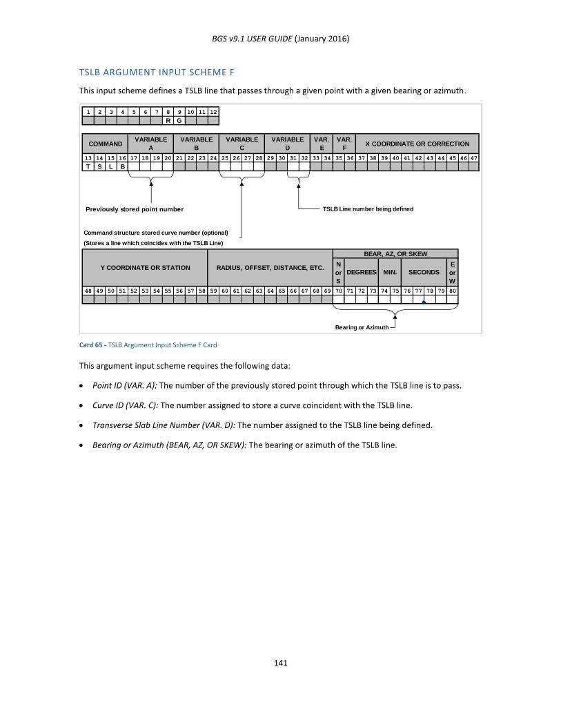
BGS v9.1 USER GUIDE (January 2016)
141
TSLB ARGUMENT INPUT SCHEME F
This input scheme defines a TSLB line that passes through a given point with a given bearing or azimuth.
Card 65 - TSLB Argument Input Scheme F Card
This argument input scheme requires the following data:
Point ID (VAR. A): The number of the previously stored point through which the TSLB line is to pass.
Curve ID (VAR. C): The number assigned to store a curve coincident with the TSLB line.
Transverse Slab Line Number (VAR. D): The number assigned to the TSLB line being defined.
Bearing or Azimuth (BEAR, AZ, OR SKEW): The bearing or azimuth of the TSLB line.
1 2 3 4 5 6 7 8 9 10 11 12
R G
13 14 15 16 17 18 19 20 21 22 23 24 25 26 27 28 29 30 31 32 33 34 35 36 37 38 39 40 41 42 43 44 45 46 47
T S L B
Previously stored point number TSLB Line number being defined
Command structure stored curve number (optional)
(Stores a line which coincides with the TSLB Line)
N
or
S
E
or
W
48 49 50 51 52 53 54 55 56 57 58 59 60 61 62 63 64 65 66 67 68 69 70 71 72 73 74 75 76 77 78 79 80
Bearing or Azimuth
VARIABLE
D
VAR.
E
VAR.
FX COORDINATE OR CORRECTIONCOMMAND
VARIABLE
A
VARIABLE
B
VARIABLE
C
Y COORDINATE OR STATION RADIUS, OFFSET, DISTANCE, ETC.
BEAR, AZ, OR SKEW
DEGREES MIN. SECONDS
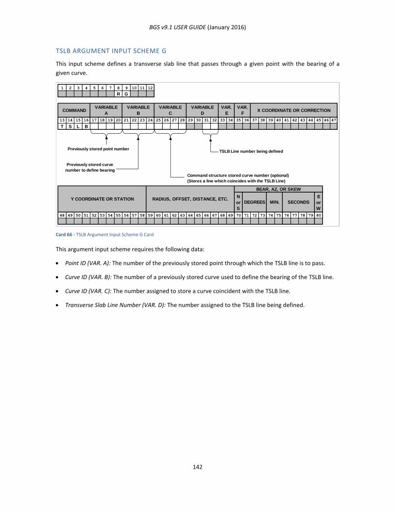
BGS v9.1 USER GUIDE (January 2016)
142
TSLB ARGUMENT INPUT SCHEME G
This input scheme defines a transverse slab line that passes through a given point with the bearing of a
given curve.
Card 66 - TSLB Argument Input Scheme G Card
This argument input scheme requires the following data:
Point ID (VAR. A): The number of the previously stored point through which the TSLB line is to pass.
Curve ID (VAR. B): The number of a previously stored curve used to define the bearing of the TSLB line.
Curve ID (VAR. C): The number assigned to store a curve coincident with the TSLB line.
Transverse Slab Line Number (VAR. D): The number assigned to the TSLB line being defined.
1 2 3 4 5 6 7 8 9 10 11 12
R G
13 14 15 16 17 18 19 20 21 22 23 24 25 26 27 28 29 30 31 32 33 34 35 36 37 38 39 40 41 42 43 44 45 46 47
T S L B
Previously stored point numberTSLB Line number being defined
Previously stored curve
number to define bearing
Command structure stored curve number (optional)
(Stores a line which coincides with the TSLB Line)
N
or
S
E
or
W
48 49 50 51 52 53 54 55 56 57 58 59 60 61 62 63 64 65 66 67 68 69 70 71 72 73 74 75 76 77 78 79 80
VARIABLE
C
VARIABLE
B
VARIABLE
ACOMMAND X COORDINATE OR CORRECTION
VAR.
F
VAR.
E
VARIABLE
D
Y COORDINATE OR STATION RADIUS, OFFSET, DISTANCE, ETC.
BEAR, AZ, OR SKEW
DEGREES MIN. SECONDS
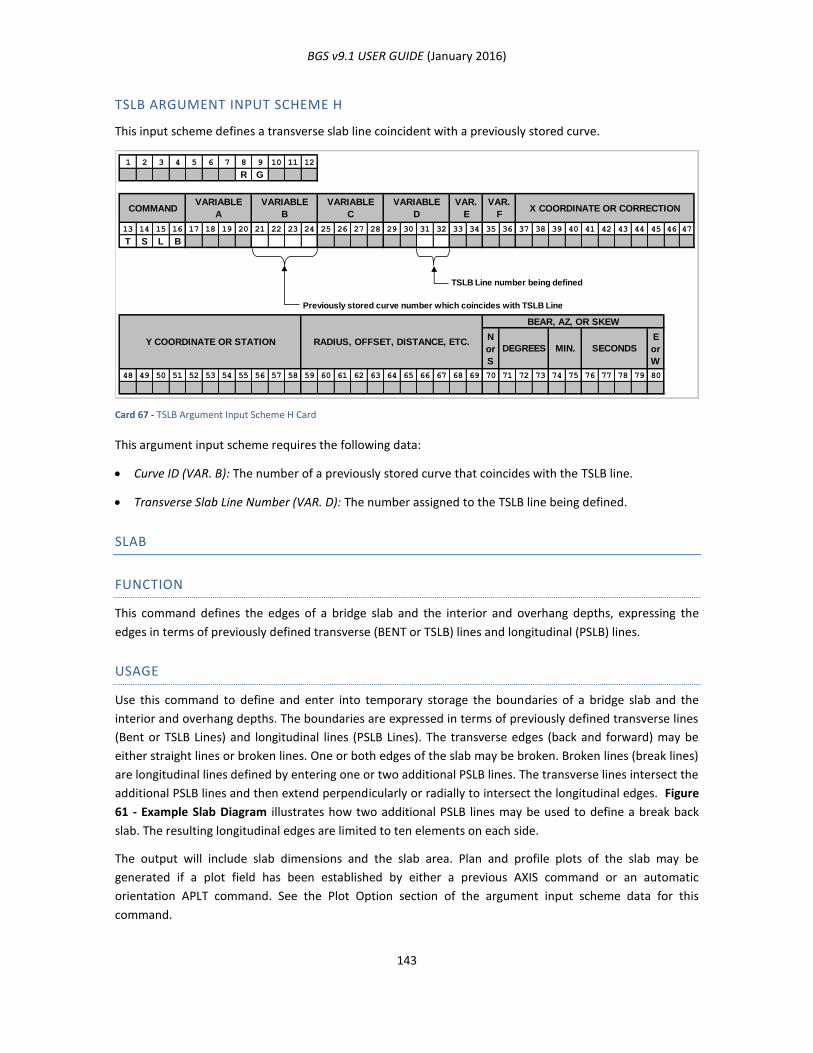
BGS v9.1 USER GUIDE (January 2016)
143
TSLB ARGUMENT INPUT SCHEME H
This input scheme defines a transverse slab line coincident with a previously stored curve.
Card 67 - TSLB Argument Input Scheme H Card
This argument input scheme requires the following data:
Curve ID (VAR. B): The number of a previously stored curve that coincides with the TSLB line.
Transverse Slab Line Number (VAR. D): The number assigned to the TSLB line being defined.
SLAB
FUNCTION
This command defines the edges of a bridge slab and the interior and overhang depths, expressing the
edges in terms of previously defined transverse (BENT or TSLB) lines and longitudinal (PSLB) lines.
USAGE
Use this command to define and enter into temporary storage the boundaries of a bridge slab and the
interior and overhang depths. The boundaries are expressed in terms of previously defined transverse lines
(Bent or TSLB Lines) and longitudinal lines (PSLB Lines). The transverse edges (back and forward) may be
either straight lines or broken lines. One or both edges of the slab may be broken. Broken lines (break lines)
are longitudinal lines defined by entering one or two additional PSLB lines. The transverse lines intersect the
additional PSLB lines and then extend perpendicularly or radially to intersect the longitudinal edges. Figure
61 - Example Slab Diagram illustrates how two additional PSLB lines may be used to define a break back
slab. The resulting longitudinal edges are limited to ten elements on each side.
The output will include slab dimensions and the slab area. Plan and profile plots of the slab may be
generated if a plot field has been established by either a previous AXIS command or an automatic
orientation APLT command. See the Plot Option section of the argument input scheme data for this
command.
1 2 3 4 5 6 7 8 9 10 11 12
R G
13 14 15 16 17 18 19 20 21 22 23 24 25 26 27 28 29 30 31 32 33 34 35 36 37 38 39 40 41 42 43 44 45 46 47
T S L B
TSLB Line number being defined
Previously stored curve number which coincides with TSLB Line
N
or
S
E
or
W
48 49 50 51 52 53 54 55 56 57 58 59 60 61 62 63 64 65 66 67 68 69 70 71 72 73 74 75 76 77 78 79 80
VARIABLE
D
VAR.
E
VAR.
FX COORDINATE OR CORRECTIONCOMMAND
VARIABLE
A
VARIABLE
B
VARIABLE
C
Y COORDINATE OR STATION RADIUS, OFFSET, DISTANCE, ETC.
BEAR, AZ, OR SKEW
DEGREES MIN. SECONDS
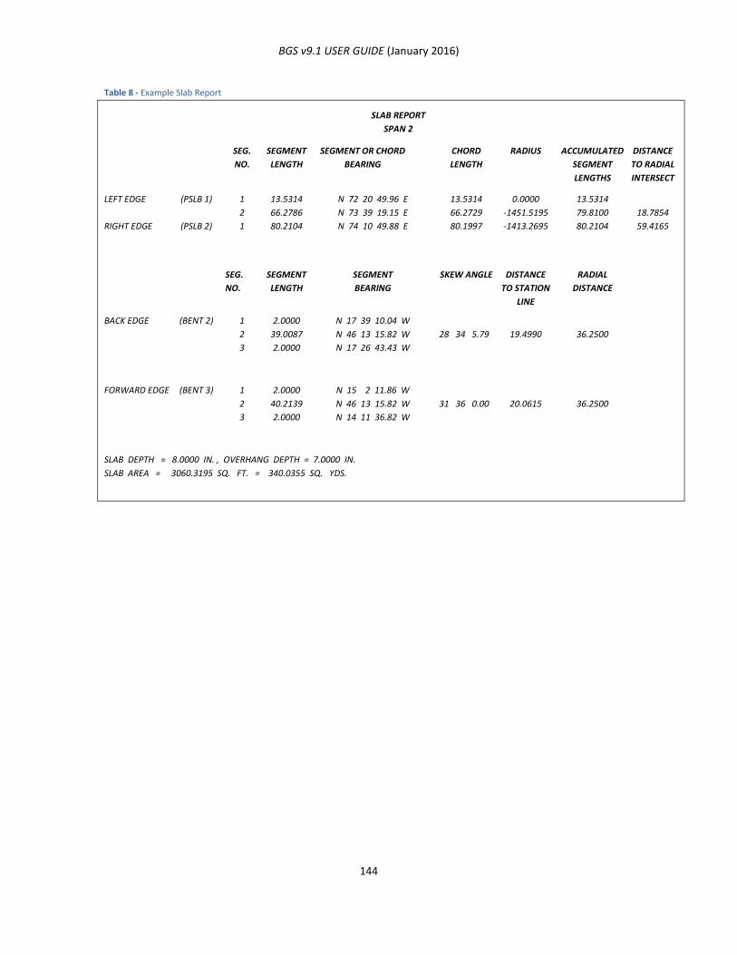
BGS v9.1 USER GUIDE (January 2016)
144
Table 8 - Example Slab Report
SLAB REPORT
SPAN 2
SEG.
NO.
SEGMENT
LENGTH
SEGMENT OR CHORD
BEARING
CHORD
LENGTH
RADIUS ACCUMULATED
SEGMENT
LENGTHS
DISTANCE
TO RADIAL
INTERSECT
LEFT EDGE
RIGHT EDGE
(PSLB 1)
(PSLB 2)
1
2
1
13.5314
66.2786
80.2104
N 72 20 49.96 E
N 73 39 19.15 E
N 74 10 49.88 E
13.5314
66.2729
80.1997
0.0000
-1451.5195
-1413.2695
13.5314
79.8100
80.2104
18.7854
59.4165
SEG.
NO.
SEGMENT
LENGTH
SEGMENT
BEARING
SKEW ANGLE DISTANCE
TO STATION
LINE
RADIAL
DISTANCE
BACK EDGE (BENT 2) 1
2
3
2.0000
39.0087
2.0000
N 17 39 10.04 W
N 46 13 15.82 W
N 17 26 43.43 W
28 34 5.79
19.4990
36.2500
FORWARD EDGE (BENT 3) 1
2
3
2.0000
40.2139
2.0000
N 15 2 11.86 W
N 46 13 15.82 W
N 14 11 36.82 W
31 36 0.00
20.0615
36.2500
SLAB DEPTH = 8.0000 IN. , OVERHANG DEPTH = 7.0000 IN.
SLAB AREA = 3060.3195 SQ. FT. = 340.0355 SQ. YDS.
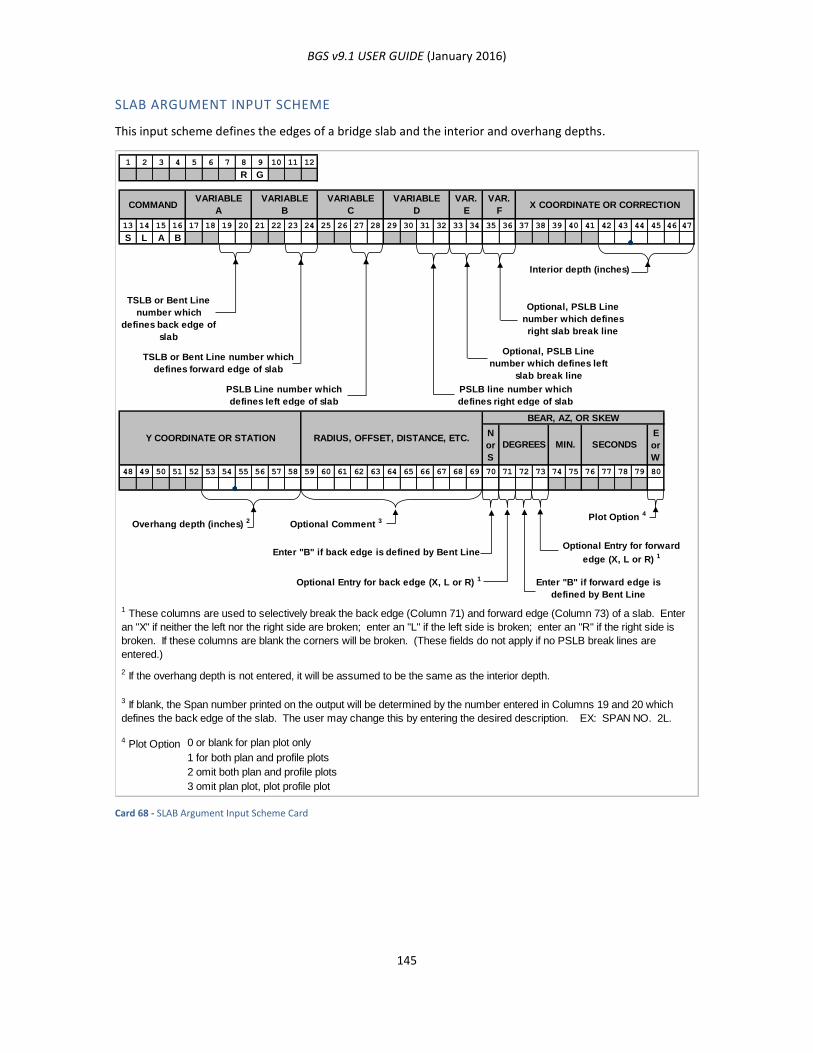
BGS v9.1 USER GUIDE (January 2016)
145
SLAB ARGUMENT INPUT SCHEME
This input scheme defines the edges of a bridge slab and the interior and overhang depths.
Card 68 - SLAB Argument Input Scheme Card
1 2 3 4 5 6 7 8 9 10 11 12
R G
13 14 15 16 17 18 19 20 21 22 23 24 25 26 27 28 29 30 31 32 33 34 35 36 37 38 39 40 41 42 43 44 45 46 47
S L A B
Interior depth (inches)
TSLB or Bent Line
number which
defines back edge of
slab
Optional, PSLB Line
number which defines
right slab break line
TSLB or Bent Line number which
defines forward edge of slab
Optional, PSLB Line
number which defines left
slab break line
PSLB Line number which
defines left edge of slab
PSLB line number which
defines right edge of slab
N
or
S
E
or
W
48 49 50 51 52 53 54 55 56 57 58 59 60 61 62 63 64 65 66 67 68 69 70 71 72 73 74 75 76 77 78 79 80
Overhang depth (inches) 2 Optional Comment 3 Plot Option 4
Enter "B" if back edge is defined by Bent LineOptional Entry for forward
edge (X, L or R) 1
Optional Entry for back edge (X, L or R) 1 Enter "B" if forward edge is
defined by Bent Line
0 or blank for plan plot only
1 for both plan and profile plots
2 omit both plan and profile plots
3 omit plan plot, plot profile plot
4 Plot Option
1 These columns are used to selectively break the back edge (Column 71) and forward edge (Column 73) of a slab. Enter
an "X" if neither the left nor the right side are broken; enter an "L" if the left side is broken; enter an "R" if the right side is
broken. If these columns are blank the corners will be broken. (These fields do not apply if no PSLB break lines are
entered.)
2 If the overhang depth is not entered, it will be assumed to be the same as the interior depth.
3 If blank, the Span number printed on the output will be determined by the number entered in Columns 19 and 20 which
defines the back edge of the slab. The user may change this by entering the desired description. EX: SPAN NO. 2L.
Y COORDINATE OR STATION RADIUS, OFFSET, DISTANCE, ETC.
BEAR, AZ, OR SKEW
DEGREES MIN. SECONDS
VARIABLE
D
VAR.
E
VAR.
FX COORDINATE OR CORRECTIONCOMMAND
VARIABLE
A
VARIABLE
B
VARIABLE
C
BGS v9.1 USER GUIDE (January 2016)
146
This argument input scheme requires the following data:
Back and Forward Slab Edges (VAR A and VAR B): The numbers of the BENT or TSLB lines that form the
back and forward slab edges.
Left and Right Slab Edges (VAR C and VAR D): The numbers of the PSLB lines that form the left and right
slab edges.
Left and Right Break Lines (VAR E and VAR F) (optional): The numbers of the PSLB lines that form the left
and right break lines. Both of these numbers may be given, either one may be given, or both may be
omitted.
Interior and Overhang Depth (X-COORDINATE OR CORRECTION and Y-COORDINATEOR STATION): The
depth of the interior and overhang portions of the slab.
Title (RADIUS, OFFSET, ETC) (optional): The title for the slab elevations report.
Back/Forward Edge Flag (BEAR, AZ, OR SKEW): If the back or forward edge is defined by a BENT
command, enter B here. Otherwise, leave blank.
Slab Break Options (BEAR, AZ, OR SKEW): Used to selectively break back the back and forward edges of
the slab. Enter X if neither the left nor right side is broken. Enter L if only the left side is broken. Enter R
if only the right side is broken. If these fields are left blank the corners will be broken. These fields do
not apply if no PSLB break lines are entered.
Plot Option (BEAR, AZ, OR SKEW): Enter “0” to produce a plan plot and omit a profile plot, “1” to
produce a plan plot and a profile plot, “2” to omit both a plan plot and a profile plot, or “3” to omit a
plan plot and produce a profile plot.
NOTES ON SLAB COMMAND
SCALES
Horizontal scale = 1:1; that is, one foot to one foot, or one meter to one meter. Thus, there is no scale
factor.
Vertical Scale = profile scale on SLEL
The vertical scale factor may be entered on any SLEL card immediately following a SLAB card. If
the vertical scale factor is changing for each SLEL card, the profile plots will be broken into
individual plots.
If no vertical scale is entered, the default scale is 1” = 20 feet per foot, or 1 meter = 20 meters.
ANNOTATION (SEE FIGURE 57 - EXAMPLE SLAB LINE ELEVATION PLOT)
Title as in Name card with “SURFACE ELEVATION LEFT SLAB LINE” or “SURFACE ELEVATION RIGHT SLAB
LINE.”
Profiles – line connected elevations at slab edge points with “0” mark for each end of slab line.
Axis – elevations at every inch on vertical axis, mark “+” and distance in feet at end slab lines on
horizontal axis.

BGS v9.1 USER GUIDE (January 2016)
147
Figure 57 - Example Slab Line Elevation Plot
DATA PLOTTED
Surface elevations versus true slab distances
LOCATION OF PLOTS
After slab plan plot, on two axes –
top axis for left slab line
bottom axis for right slab line
Note that if a profile plot is desired at a scale other than 20 ft/in or 20 m/m, the scale must be entered on a
SLEL card.
SLEL (SLAB ELEVATIONS)
FUNCTION
This command calculates and outputs a tabulation of distances, surface elevations, bottom-of-slab
elevations, and bottom-of-slab elevations plus deflection along the edges of the slab. This command must
be immediately preceded by a SLAB or another SLEL command. Note the following:
Elevations are tabulated at either an incremented or at equal divisions along the transverse and
longitudinal edges of the slab.
If a slab has a broken transverse edge, the increments or divisions will start at the break line rather
than the outside edge. However, the tabulation will include the outside points and any increments
that fall between the outside edge and the break.
For transverse edges, bottom-of-slab elevations use the interior slab depth. For longitudinal edges,
bottom-of-slab elevations use the overhang slab depth.
297.5
RAINBOW BRIDGE
SURFACE ELEVATION
SCALE:
LEFT SLAB LINE
M = 1 INCH = 20.0 FEET
V = 1 INCH = 2.5 FEET
297.5
295.0 295.0
292.5 292.5
290.0 290.0
287.5 287.5
285.0 285.0
282.5 282.5
280.0 280.0
277.5
0.0 Bent 8-9 Bent 9-10 Bent 10-11 Bent 11-1275.0 150.0 225.0 301.0
277.5

BGS v9.1 USER GUIDE (January 2016)
148
For curved longitudinal edges, chord and offset distances are tabulated as well. See Figure 58 -
Plan View Showing Location of Slab Elevations.
Figure 58 - Plan View Showing Location of Slab Elevations
USAGE
Use this command to produce a tabulation of distances, surface elevations, bottom of slab elevations, and
bottom of slab elevations plus deflection along the boundaries of the slab.
SLEL ARGUMENT INPUT SCHEME A
Calculates and outputs elevations at an incremented distance along the transverse and longitudinal edges
of the slab.
Distances Along Edge of Slab Edge of Slab
C Bent
C Bent Distances Along Chord
L
L
PT1 PT2
PT3
90 PT4
PT5
Offset Distances From Chord to Edge of Slab
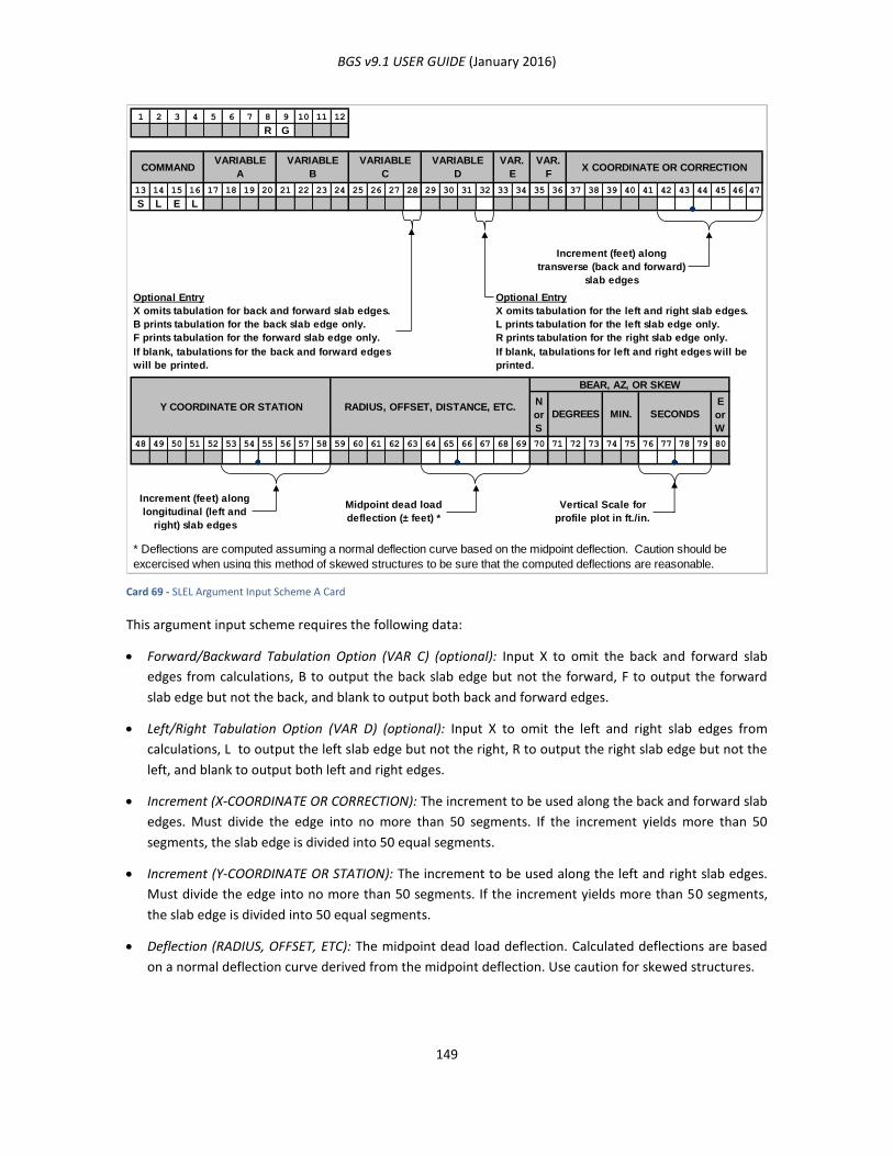
BGS v9.1 USER GUIDE (January 2016)
149
Card 69 - SLEL Argument Input Scheme A Card
This argument input scheme requires the following data:
Forward/Backward Tabulation Option (VAR C) (optional): Input X to omit the back and forward slab
edges from calculations, B to output the back slab edge but not the forward, F to output the forward
slab edge but not the back, and blank to output both back and forward edges.
Left/Right Tabulation Option (VAR D) (optional): Input X to omit the left and right slab edges from
calculations, L to output the left slab edge but not the right, R to output the right slab edge but not the
left, and blank to output both left and right edges.
Increment (X-COORDINATE OR CORRECTION): The increment to be used along the back and forward slab
edges. Must divide the edge into no more than 50 segments. If the increment yields more than 50
segments, the slab edge is divided into 50 equal segments.
Increment (Y-COORDINATE OR STATION): The increment to be used along the left and right slab edges.
Must divide the edge into no more than 50 segments. If the increment yields more than 50 segments,
the slab edge is divided into 50 equal segments.
Deflection (RADIUS, OFFSET, ETC): The midpoint dead load deflection. Calculated deflections are based
on a normal deflection curve derived from the midpoint deflection. Use caution for skewed structures.
1 2 3 4 5 6 7 8 9 10 11 12
R G
13 14 15 16 17 18 19 20 21 22 23 24 25 26 27 28 29 30 31 32 33 34 35 36 37 38 39 40 41 42 43 44 45 46 47
S L E L
Increment (feet) along
transverse (back and forward)
slab edges
Optional Entry Optional Entry
X omits tabulation for back and forward slab edges. X omits tabulation for the left and right slab edges.
B prints tabulation for the back slab edge only. L prints tabulation for the left slab edge only.
F prints tabulation for the forward slab edge only. R prints tabulation for the right slab edge only.
N
or
S
E
or
W
48 49 50 51 52 53 54 55 56 57 58 59 60 61 62 63 64 65 66 67 68 69 70 71 72 73 74 75 76 77 78 79 80
Increment (feet) along
longitudinal (left and
right) slab edges
Midpoint dead load
deflection (± feet) *
Vertical Scale for
profile plot in ft./in.
RADIUS, OFFSET, DISTANCE, ETC.Y COORDINATE OR STATION
X COORDINATE OR CORRECTION
SECONDSMIN.DEGREES
BEAR, AZ, OR SKEW
* Deflections are computed assuming a normal deflection curve based on the midpoint deflection. Caution should be
excercised when using this method of skewed structures to be sure that the computed deflections are reasonable.
If blank, tabulations for the back and forward edges
will be printed.
If blank, tabulations for left and right edges will be
printed.
COMMANDVARIABLE
A
VARIABLE
B
VARIABLE
C
VARIABLE
D
VAR.
E
VAR.
F
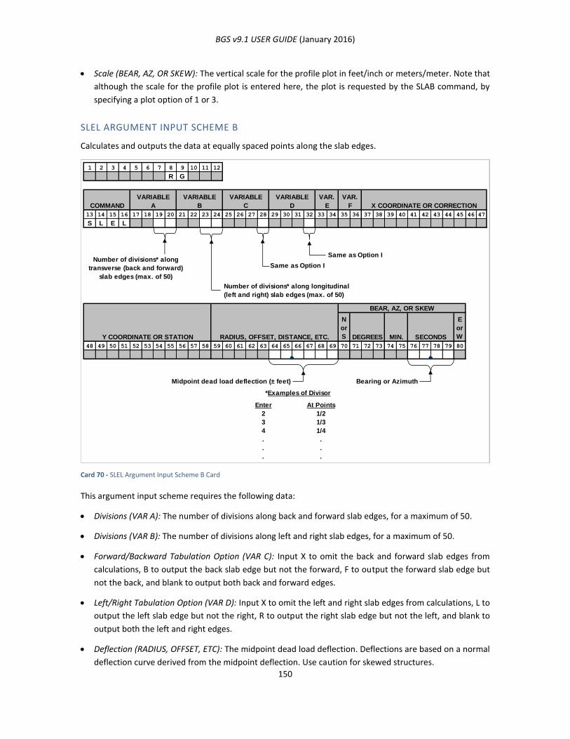
BGS v9.1 USER GUIDE (January 2016)
150
Scale (BEAR, AZ, OR SKEW): The vertical scale for the profile plot in feet/inch or meters/meter. Note that
although the scale for the profile plot is entered here, the plot is requested by the SLAB command, by
specifying a plot option of 1 or 3.
SLEL ARGUMENT INPUT SCHEME B
Calculates and outputs the data at equally spaced points along the slab edges.
Card 70 - SLEL Argument Input Scheme B Card
This argument input scheme requires the following data:
Divisions (VAR A): The number of divisions along back and forward slab edges, for a maximum of 50.
Divisions (VAR B): The number of divisions along left and right slab edges, for a maximum of 50.
Forward/Backward Tabulation Option (VAR C): Input X to omit the back and forward slab edges from
calculations, B to output the back slab edge but not the forward, F to output the forward slab edge but
not the back, and blank to output both back and forward edges.
Left/Right Tabulation Option (VAR D): Input X to omit the left and right slab edges from calculations, L to
output the left slab edge but not the right, R to output the right slab edge but not the left, and blank to
output both the left and right edges.
Deflection (RADIUS, OFFSET, ETC): The midpoint dead load deflection. Deflections are based on a normal
deflection curve derived from the midpoint deflection. Use caution for skewed structures.
1 2 3 4 5 6 7 8 9 10 11 12
R G
13 14 15 16 17 18 19 20 21 22 23 24 25 26 27 28 29 30 31 32 33 34 35 36 37 38 39 40 41 42 43 44 45 46 47
S L E L
Number of divisions* along
transverse (back and forward)
slab edges (max. of 50)
Same as Option I
Same as Option I
N
or
S
E
or
W
48 49 50 51 52 53 54 55 56 57 58 59 60 61 62 63 64 65 66 67 68 69 70 71 72 73 74 75 76 77 78 79 80
Midpoint dead load deflection (± feet) Bearing or Azimuth
*Examples of Divisor
At Points
2
3
4
. .
. .
. .
1/3
1/4
COMMAND
VARIABLE
A
VARIABLE
B
VARIABLE
C
VARIABLE
D
VAR.
E
Y COORDINATE OR STATION RADIUS, OFFSET, DISTANCE, ETC.
VAR.
F X COORDINATE OR CORRECTION
Enter
1/2
BEAR, AZ, OR SKEW
DEGREES MIN. SECONDS
Number of divisions* along longitudinal
(left and right) slab edges (max. of 50)

BGS v9.1 USER GUIDE (January 2016)
151
Scale (BEAR, AZ, OR SKEW): The vertical scale for the profile plot in feet/inch. Note that although the
scale for the profile plot is entered here, the plot is requested by the SLAB command, by specifying a
plot option of 1 or 3.
BENT (BENT LINE)
FUNCTION
This command defines a bent line, which is a straight line representing the centerline of a bent or another
supporting member of the structure.
USAGE
Use this command to define straight lines which represent the centerline of bents or other supporting
members for structures. These bent lines may be for either simple or continuous units. The BENT command
accomplishes the storage of bent lines. Designating a line as a bent line tells the system how it is to be
treated in connection with intersections, framing layouts and other computations. Bent lines must be
numbered consecutively from the beginning of the bridge to the end of the bridge; as many as 75 bents
may be defined for a given structure. Bent line numbers are structure-dependent—that is, they may be
repeated but must be redefined for a different structure under a different NAME command. Bent Lines may
be defined by eight transverse line options similar to those used for defining TSLB Lines.
BENT ARGUMENT INPUT SCHEME A
This input scheme defines a bent line which crosses the bridge alignment at a given station. A bearing,
azimuth, or skew may be entered at the user’s option.
Card 71 - BENT Argument Input Scheme A Card
1 2 3 4 5 6 7 8 9 10 11 12
R G
13 14 15 16 17 18 19 20 21 22 23 24 25 26 27 28 29 30 31 32 33 34 35 36 37 38 39 40 41 42 43 44 45 46 47
B E N T
Bent Type:
AB - Abutment
PR - Pier
TR - Transition
IN
— Interior
Blank
Bent Line number being defined
N
or
S
E
or
W
48 49 50 51 52 53 54 55 56 57 58 59 60 61 62 63 64 65 66 67 68 69 70 71 72 73 74 75 76 77 78 79 80
Station where Bent Line crosses
bridge alignment
Depth to Reference Line
(feet) *Bearing, Azimuth or Skew
Command structure stored curve number
(optional)
(Stores a line which coincides with the Bent Line)
X COORDINATE OR CORRECTIONVAR.
F
VAR.
E
VARIABLE
D
VARIABLE
C
VARIABLE
B
VARIABLE
ACOMMAND
RADIUS, OFFSET, DISTANCE, ETC.Y COORDINATE OR STATIONSECONDSMIN.DEGREES
BEAR, AZ, OR SKEW
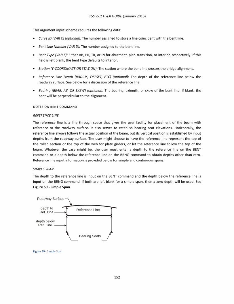
BGS v9.1 USER GUIDE (January 2016)
152
This argument input scheme requires the following data:
Curve ID (VAR C) (optional): The number assigned to store a line coincident with the bent line.
Bent Line Number (VAR D): The number assigned to the bent line.
Bent Type (VAR F): Either AB, PR, TR, or IN for abutment, pier, transition, or interior, respectively. If this
field is left blank, the bent type defaults to interior.
Station (Y-COORDINATE OR STATION): The station where the bent line crosses the bridge alignment.
Reference Line Depth (RADIUS, OFFSET, ETC) (optional): The depth of the reference line below the
roadway surface. See below for a discussion of the reference line.
Bearing (BEAR, AZ, OR SKEW) (optional): The bearing, azimuth, or skew of the bent line. If blank, the
bent will be perpendicular to the alignment.
NOTES ON BENT COMMAND
REFERENCE LINE
The reference line is a line through space that gives the user facility for placement of the beam with
reference to the roadway surface. It also serves to establish bearing seat elevations. Horizontally, the
reference line always follows the actual position of the beam, but its vertical position is established by input
depths from the roadway surface. The user might choose to have the reference line represent the top of
the rolled section or the top of the web for plate girders, or let the reference line follow the top of the
beam. Whatever the case might be, the user must enter a depth to the reference line on the BENT
command or a depth below the reference line on the BRNG command to obtain depths other than zero.
Reference line input information is provided below for simple and continuous spans.
SIMPLE SPAN
The depth to the reference line is input on the BENT command and the depth below the reference line is
input on the BRNG command. If both are left blank for a simple span, then a zero depth will be used. See
Figure 59 - Simple Span.
Figure 59 - Simple Span
Roadway Surface
depth to Ref. Line
depth below Ref. Line
Bearing Seats
Reference Line
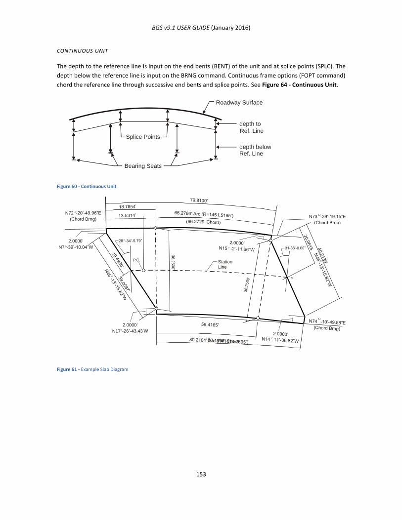
BGS v9.1 USER GUIDE (January 2016)
153
CONTINUOUS UNIT
The depth to the reference line is input on the end bents (BENT) of the unit and at splice points (SPLC). The
depth below the reference line is input on the BRNG command. Continuous frame options (FOPT command)
chord the reference line through successive end bents and splice points. See Figure 64 - Continuous Unit.
Figure 60 - Continuous Unit
Figure 61 - Example Slab Diagram
Roadway Surface
depth to Ref. Line
depth below Ref. Line
Bearing Seats
Splice Points
Station Line
2.0000’
N7 O-39’-10.04”W
28 O-34’-5.79”
2.0000’
N17O-26’-43.43’W
3 6 . 2 5 0 0 ’
N73 O
-39’-19.15”E
(Chord Brng)
N72 O-20’-49.96”E
(Chord Brng)
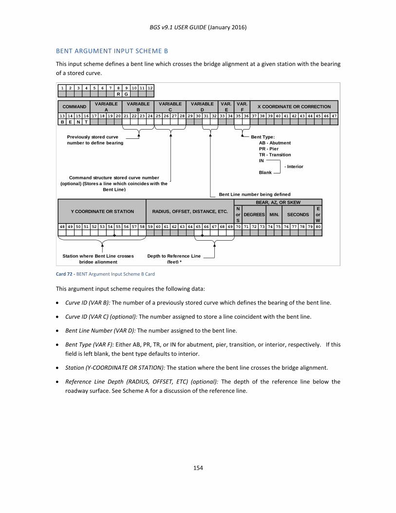
BGS v9.1 USER GUIDE (January 2016)
154
BENT ARGUMENT INPUT SCHEME B
This input scheme defines a bent line which crosses the bridge alignment at a given station with the bearing
of a stored curve.
Card 72 - BENT Argument Input Scheme B Card
This argument input scheme requires the following data:
Curve ID (VAR B): The number of a previously stored curve which defines the bearing of the bent line.
Curve ID (VAR C) (optional): The number assigned to store a line coincident with the bent line.
Bent Line Number (VAR D): The number assigned to the bent line.
Bent Type (VAR F): Either AB, PR, TR, or IN for abutment, pier, transition, or interior, respectively. If this
field is left blank, the bent type defaults to interior.
Station (Y-COORDINATE OR STATION): The station where the bent line crosses the bridge alignment.
Reference Line Depth (RADIUS, OFFSET, ETC) (optional): The depth of the reference line below the
roadway surface. See Scheme A for a discussion of the reference line.
1 2 3 4 5 6 7 8 9 10 11 12
R G
13 14 15 16 17 18 19 20 21 22 23 24 25 26 27 28 29 30 31 32 33 34 35 36 37 38 39 40 41 42 43 44 45 46 47
B E N T
Bent Type:
AB - Abutment
PR - Pier
TR - Transition
IN
- Interior
Blank
Bent Line number being defined
N
or
S
E
or
W
48 49 50 51 52 53 54 55 56 57 58 59 60 61 62 63 64 65 66 67 68 69 70 71 72 73 74 75 76 77 78 79 80
Station where Bent Line crosses
bridge alignment
Depth to Reference Line
(feet) *
RADIUS, OFFSET, DISTANCE, ETC.Y COORDINATE OR STATIONSECONDSMIN.DEGREES
BEAR, AZ, OR SKEW
VARIABLE
D
VAR.
E
VAR.
FX COORDINATE OR CORRECTION
Command structure stored curve number
(optional) (Stores a line which coincides with the
Bent Line)
Previously stored curve
number to define bearing
COMMANDVARIABLE
A
VARIABLE
B
VARIABLE
C

BGS v9.1 USER GUIDE (January 2016)
155
BENT ARGUMENT INPUT SCHEME C
This input scheme defines a bent line through a given point and at a given bearing.
Card 73 - BENT Argument Input Scheme C Card
This argument input scheme requires the following data:
Curve ID (VAR C) (optional): The number assigned to store a line coincident with the bent line.
Bent Line Number (VAR D): The number assigned to the bent line.
Bent Type (VAR F): Either AB, PR, TR, or IN for abutment, pier, transition, or interior, respectively. If this
field is left blank, the bent type defaults to interior.
X-Coordinate (X-COORDINATE OR CORRECTION): The X-coordinate of the given point.
Y-Coordinate (Y-COORDINATE OR STATION): The Y-coordinate of the given point.
Reference Line Depth (RADIUS, OFFSET, ETC) (optional): The depth of the reference line below the
roadway surface. See Scheme A for a discussion of the reference line.
Bearing or azimuth (BEAR, AZ, OR SKEW): The bearing or azimuth of the bent line.
1 2 3 4 5 6 7 8 9 10 11 12
R G
13 14 15 16 17 18 19 20 21 22 23 24 25 26 27 28 29 30 31 32 33 34 35 36 37 38 39 40 41 42 43 44 45 46 47
B E N T
X- Coordinate
Bent Type: AB, PR, TR, IN, blank
(Refer to Schemes A-B)
Bent Line number being defined
N
or
S
E
or
W
48 49 50 51 52 53 54 55 56 57 58 59 60 61 62 63 64 65 66 67 68 69 70 71 72 73 74 75 76 77 78 79 80
Y- Coordinate Bearing or AzimuthDepth to Reference Line (feet) *
RADIUS, OFFSET, DISTANCE, ETC.Y COORDINATE OR STATIONSECONDSMIN.DEGREES
BEAR, AZ, OR SKEW
Command structure stored curve number
(optional) (Stores a line which coincides with the
Bent Line)
X COORDINATE OR CORRECTIONVAR.
F
VAR.
E
VARIABLE
D
VARIABLE
C
VARIABLE
B
VARIABLE
ACOMMAND

BGS v9.1 USER GUIDE (January 2016)
156
BENT ARGUMENT INPUT SCHEME D
This input scheme defines a bent line through a given point and at the bearing of a previously stored curve.
Card 74 - BENT Argument Input Scheme D Card
This argument input scheme requires the following data:
Curve Number (VAR B): The number of a previously stored curve to define the bearing of the bent line.
Curve ID (VAR C) (optional): The number assigned to store a line coincident with the bent line.
Bent Line Number (VAR D): The number assigned to the bent line.
Bent Type (VAR F): Either AB, PR, TR, or IN for abutment, pier, transition, or interior, respectively. If this
field is left blank, the bent type defaults to interior.
X-Coordinate (X-COORDINATE OR CORRECTION): The X-coordinate of the given point.
Y-Coordinate (Y-COORDINATE OR STATION): The Y-coordinate of the given point.
Reference Line Depth (RADIUS, OFFSET, ETC) (optional): The depth of the reference line below the
roadway surface. See Scheme A for a discussion of the reference line.
1 2 3 4 5 6 7 8 9 10 11 12
R G
13 14 15 16 17 18 19 20 21 22 23 24 25 26 27 28 29 30 31 32 33 34 35 36 37 38 39 40 41 42 43 44 45 46 47
B E N T
X- Coordinate
Bent Type: AB, PR, TR, IN, blank
(Refer to Schemes A-B)
(Stores a line which coincides with the
Bent Line)Bent Line number being defined
N
or
S
E
or
W
48 49 50 51 52 53 54 55 56 57 58 59 60 61 62 63 64 65 66 67 68 69 70 71 72 73 74 75 76 77 78 79 80
Y- Coordinate Depth to Reference Line (feet) *
VARIABLE
C
VARIABLE
B
VARIABLE
ACOMMAND X COORDINATE OR CORRECTION
VAR.
F
VAR.
E
VARIABLE
D
Command structure stored curve number
(optional)
Previously stored curve
number to define bearing
SECONDSMIN.DEGREES
BEAR, AZ, OR SKEW
RADIUS, OFFSET, DISTANCE, ETC.Y COORDINATE OR STATION
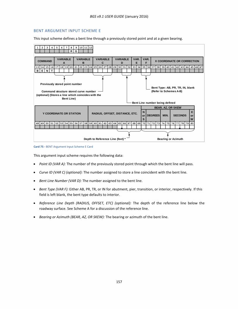
BGS v9.1 USER GUIDE (January 2016)
157
BENT ARGUMENT INPUT SCHEME E
This input scheme defines a bent line through a previously stored point and at a given bearing.
Card 75 - BENT Argument Input Scheme E Card
This argument input scheme requires the following data:
Point ID (VAR A): The number of the previously stored point through which the bent line will pass.
Curve ID (VAR C) (optional): The number assigned to store a line coincident with the bent line.
Bent Line Number (VAR D): The number assigned to the bent line.
Bent Type (VAR F): Either AB, PR, TR, or IN for abutment, pier, transition, or interior, respectively. If this
field is left blank, the bent type defaults to interior.
Reference Line Depth (RADIUS, OFFSET, ETC) (optional): The depth of the reference line below the
roadway surface. See Scheme A for a discussion of the reference line.
Bearing or Azimuth (BEAR, AZ, OR SKEW): The bearing or azimuth of the bent line.
1 2 3 4 5 6 7 8 9 10 11 12
R G
13 14 15 16 17 18 19 20 21 22 23 24 25 26 27 28 29 30 31 32 33 34 35 36 37 38 39 40 41 42 43 44 45 46 47
B E N T
Previously stored point number
Bent Type: AB, PR, TR, IN, blank
(Refer to Schemes A-B)
Bent Line number being defined
N
or
S
E
or
W
48 49 50 51 52 53 54 55 56 57 58 59 60 61 62 63 64 65 66 67 68 69 70 71 72 73 74 75 76 77 78 79 80
Depth to Reference Line (feet) * Bearing or Azimuth
Command structure stored curve number
(optional) (Stores a line which coincides with the
Bent Line)
X COORDINATE OR CORRECTIONVAR.
F
VAR.
E
VARIABLE
D
VARIABLE
C
VARIABLE
B
VARIABLE
ACOMMAND
RADIUS, OFFSET, DISTANCE, ETC.Y COORDINATE OR STATIONSECONDSMIN.DEGREES
BEAR, AZ, OR SKEW
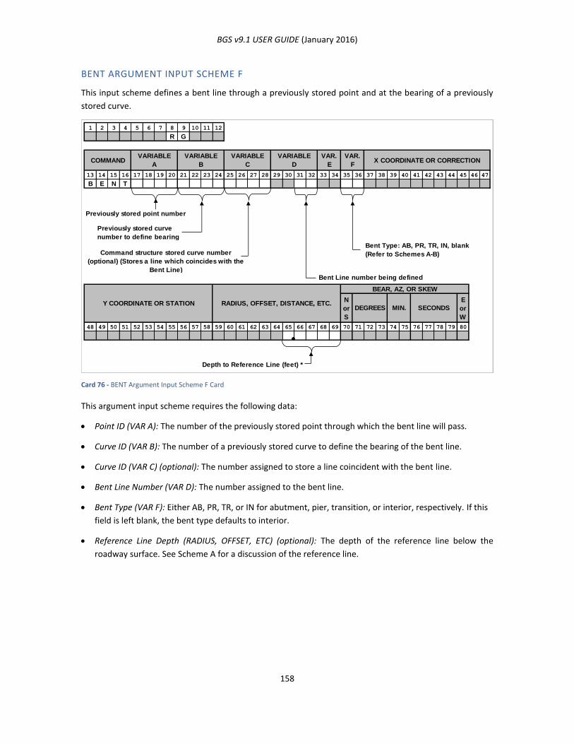
BGS v9.1 USER GUIDE (January 2016)
158
BENT ARGUMENT INPUT SCHEME F
This input scheme defines a bent line through a previously stored point and at the bearing of a previously
stored curve.
Card 76 - BENT Argument Input Scheme F Card
This argument input scheme requires the following data:
Point ID (VAR A): The number of the previously stored point through which the bent line will pass.
Curve ID (VAR B): The number of a previously stored curve to define the bearing of the bent line.
Curve ID (VAR C) (optional): The number assigned to store a line coincident with the bent line.
Bent Line Number (VAR D): The number assigned to the bent line.
Bent Type (VAR F): Either AB, PR, TR, or IN for abutment, pier, transition, or interior, respectively. If this
field is left blank, the bent type defaults to interior.
Reference Line Depth (RADIUS, OFFSET, ETC) (optional): The depth of the reference line below the
roadway surface. See Scheme A for a discussion of the reference line.
1 2 3 4 5 6 7 8 9 10 11 12
R G
13 14 15 16 17 18 19 20 21 22 23 24 25 26 27 28 29 30 31 32 33 34 35 36 37 38 39 40 41 42 43 44 45 46 47
B E N T
Previously stored point number
Bent Type: AB, PR, TR, IN, blank
(Refer to Schemes A-B)
Bent Line number being defined
N
or
S
E
or
W
48 49 50 51 52 53 54 55 56 57 58 59 60 61 62 63 64 65 66 67 68 69 70 71 72 73 74 75 76 77 78 79 80
Depth to Reference Line (feet) *
Previously stored curve
number to define bearing
Y COORDINATE OR STATION RADIUS, OFFSET, DISTANCE, ETC.DEGREES MIN.
BEAR, AZ, OR SKEW
SECONDS
Command structure stored curve number
(optional) (Stores a line which coincides with the
Bent Line)
VARIABLE
C
VARIABLE
B
VARIABLE
ACOMMAND X COORDINATE OR CORRECTION
VAR.
F
VAR.
E
VARIABLE
D
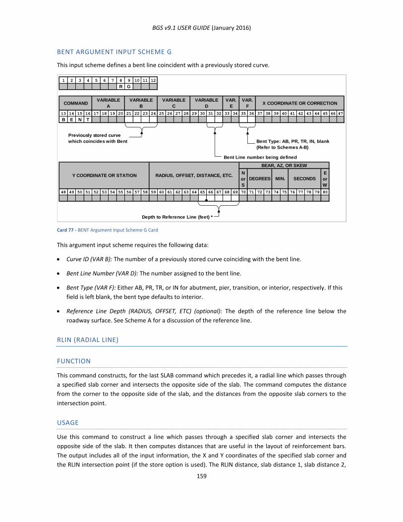
BGS v9.1 USER GUIDE (January 2016)
159
BENT ARGUMENT INPUT SCHEME G
This input scheme defines a bent line coincident with a previously stored curve.
Card 77 - BENT Argument Input Scheme G Card
This argument input scheme requires the following data:
Curve ID (VAR B): The number of a previously stored curve coinciding with the bent line.
Bent Line Number (VAR D): The number assigned to the bent line.
Bent Type (VAR F): Either AB, PR, TR, or IN for abutment, pier, transition, or interior, respectively. If this
field is left blank, the bent type defaults to interior.
Reference Line Depth (RADIUS, OFFSET, ETC) (optional): The depth of the reference line below the
roadway surface. See Scheme A for a discussion of the reference line.
RLIN (RADIAL LINE)
FUNCTION
This command constructs, for the last SLAB command which precedes it, a radial line which passes through
a specified slab corner and intersects the opposite side of the slab. The command computes the distance
from the corner to the opposite side of the slab, and the distances from the opposite slab corners to the
intersection point.
USAGE
Use this command to construct a line which passes through a specified slab corner and intersects the
opposite side of the slab. It then computes distances that are useful in the layout of reinforcement bars.
The output includes all of the input information, the X and Y coordinates of the specified slab corner and
the RLIN intersection point (if the store option is used). The RLIN distance, slab distance 1, slab distance 2,
1 2 3 4 5 6 7 8 9 10 11 12
R G
13 14 15 16 17 18 19 20 21 22 23 24 25 26 27 28 29 30 31 32 33 34 35 36 37 38 39 40 41 42 43 44 45 46 47
B E N T
Bent Type: AB, PR, TR, IN, blank
(Refer to Schemes A-B)
Bent Line number being defined
N
or
S
E
or
W
48 49 50 51 52 53 54 55 56 57 58 59 60 61 62 63 64 65 66 67 68 69 70 71 72 73 74 75 76 77 78 79 80
Depth to Reference Line (feet) *
Previously stored curve
which coincides with Bent
SECONDSMIN.DEGREES
BEAR, AZ, OR SKEW
RADIUS, OFFSET, DISTANCE, ETC.Y COORDINATE OR STATION
VARIABLE
C
VARIABLE
B
VARIABLE
ACOMMAND X COORDINATE OR CORRECTION
VAR.
F
VAR.
E
VARIABLE
D
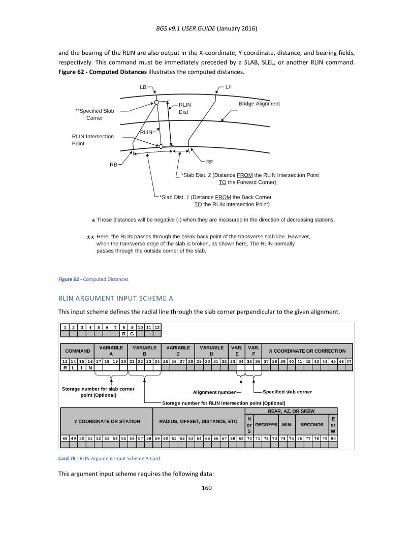
BGS v9.1 USER GUIDE (January 2016)
160
and the bearing of the RLIN are also output in the X-coordinate, Y-coordinate, distance, and bearing fields,
respectively. This command must be immediately preceded by a SLAB, SLEL, or another RLIN command.
Figure 62 - Computed Distances illustrates the computed distances.
Figure 62 - Computed Distances
RLIN ARGUMENT INPUT SCHEME A
This input scheme defines the radial line through the slab corner perpendicular to the given alignment.
Card 78 - RLIN Argument Input Scheme A Card
This argument input scheme requires the following data:
1 2 3 4 5 6 7 8 9 10 11 12
R G
13 14 15 16 17 18 19 20 21 22 23 24 25 26 27 28 29 30 31 32 33 34 35 36 37 38 39 40 41 42 43 44 45 46 47
R L I N
Storage number for slab corner
point (Optional)Alignment number
Storage number for RLIN intersection point (Optional)
N
or
S
E
or
W
48 49 50 51 52 53 54 55 56 57 58 59 60 61 62 63 64 65 66 67 68 69 70 71 72 73 74 75 76 77 78 79 80
Specified slab corner
VARIABLE
D
VAR.
E
VAR.
FX COORDINATE OR CORRECTIONCOMMAND
VARIABLE
A
VARIABLE
B
VARIABLE
C
Y COORDINATE OR STATION RADIUS, OFFSET, DISTANCE, ETC.
BEAR, AZ, OR SKEW
DEGREES MIN. SECONDS
Bridge Alignment
**Specified Slab
Corner
*Slab Dist. 2 (Distance FROM the RLIN Intersection Point
TO the Forward Corner)
*Slab Dist. 1 (Distance FROM the Back Corner
TO the RLIN Intersection Point)
RLIN
Dist
RLIN RLIN Intersection
Point
LB LF
RF RB
These distances will be negative (-) when they are measured in the direction of decreasing stations.
Here, the RLIN passes through the break-back point of the transverse slab line. However,
when the transverse edge of the slab is broken, as shown here, The RLIN normally
passes through the outside corner of the slab.
*
* *
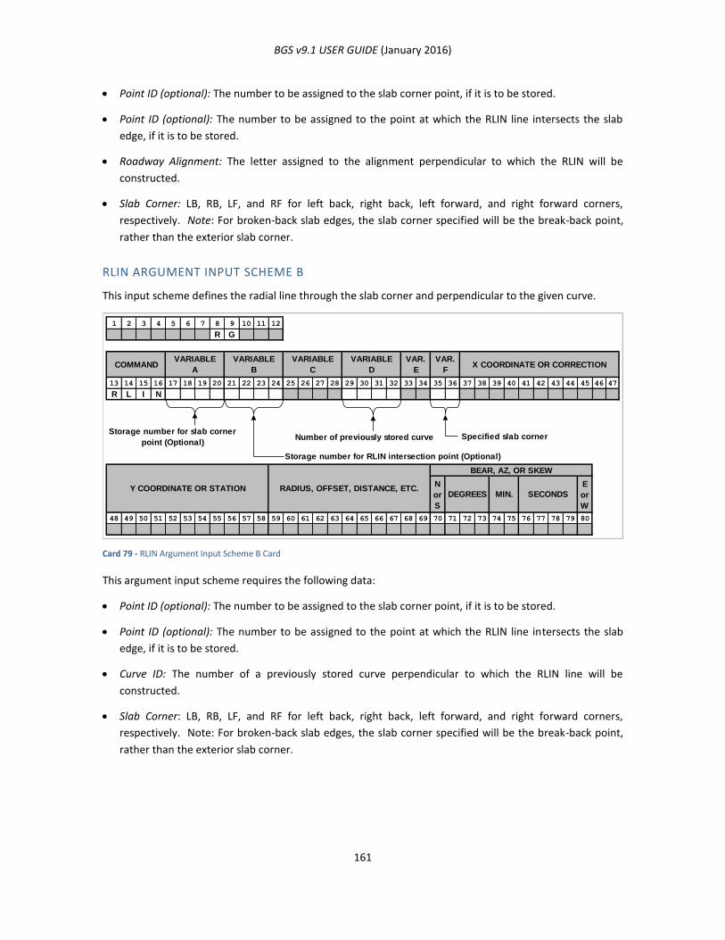
BGS v9.1 USER GUIDE (January 2016)
161
Point ID (optional): The number to be assigned to the slab corner point, if it is to be stored.
Point ID (optional): The number to be assigned to the point at which the RLIN line intersects the slab
edge, if it is to be stored.
Roadway Alignment: The letter assigned to the alignment perpendicular to which the RLIN will be
constructed.
Slab Corner: LB, RB, LF, and RF for left back, right back, left forward, and right forward corners,
respectively. Note: For broken-back slab edges, the slab corner specified will be the break-back point,
rather than the exterior slab corner.
RLIN ARGUMENT INPUT SCHEME B
This input scheme defines the radial line through the slab corner and perpendicular to the given curve.
Card 79 - RLIN Argument Input Scheme B Card
This argument input scheme requires the following data:
Point ID (optional): The number to be assigned to the slab corner point, if it is to be stored.
Point ID (optional): The number to be assigned to the point at which the RLIN line intersects the slab
edge, if it is to be stored.
Curve ID: The number of a previously stored curve perpendicular to which the RLIN line will be
constructed.
Slab Corner: LB, RB, LF, and RF for left back, right back, left forward, and right forward corners,
respectively. Note: For broken-back slab edges, the slab corner specified will be the break-back point,
rather than the exterior slab corner.
1 2 3 4 5 6 7 8 9 10 11 12
R G
13 14 15 16 17 18 19 20 21 22 23 24 25 26 27 28 29 30 31 32 33 34 35 36 37 38 39 40 41 42 43 44 45 46 47
R L I N
Storage number for slab corner
point (Optional)Number of previously stored curve
Storage number for RLIN intersection point (Optional)
N
or
S
E
or
W
48 49 50 51 52 53 54 55 56 57 58 59 60 61 62 63 64 65 66 67 68 69 70 71 72 73 74 75 76 77 78 79 80
Specified slab corner
VARIABLE
D
VAR.
E
VAR.
FX COORDINATE OR CORRECTIONCOMMAND
VARIABLE
A
VARIABLE
B
VARIABLE
C
Y COORDINATE OR STATION RADIUS, OFFSET, DISTANCE, ETC.
BEAR, AZ, OR SKEW
DEGREES MIN. SECONDS
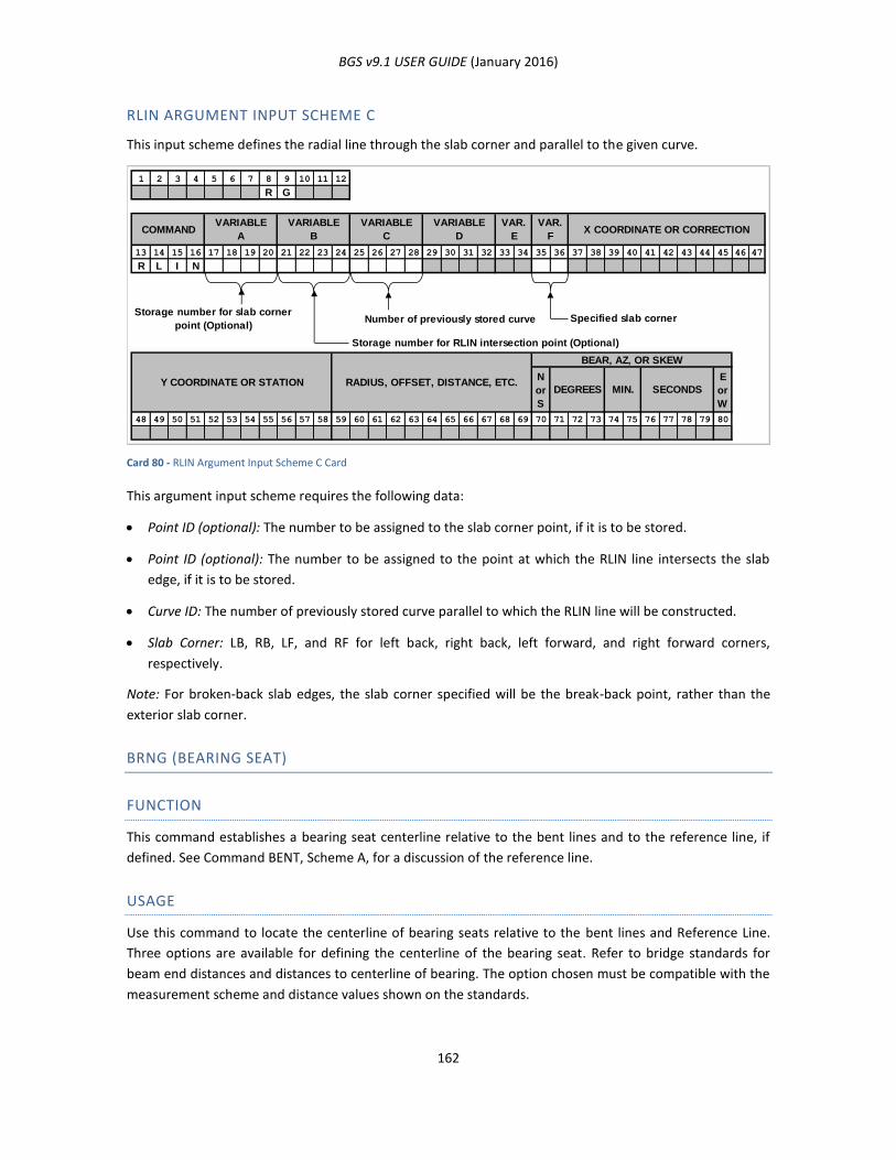
BGS v9.1 USER GUIDE (January 2016)
162
RLIN ARGUMENT INPUT SCHEME C
This input scheme defines the radial line through the slab corner and parallel to the given curve.
Card 80 - RLIN Argument Input Scheme C Card
This argument input scheme requires the following data:
Point ID (optional): The number to be assigned to the slab corner point, if it is to be stored.
Point ID (optional): The number to be assigned to the point at which the RLIN line intersects the slab
edge, if it is to be stored.
Curve ID: The number of previously stored curve parallel to which the RLIN line will be constructed.
Slab Corner: LB, RB, LF, and RF for left back, right back, left forward, and right forward corners,
respectively.
Note: For broken-back slab edges, the slab corner specified will be the break-back point, rather than the
exterior slab corner.
BRNG (BEARING SEAT)
FUNCTION
This command establishes a bearing seat centerline relative to the bent lines and to the reference line, if
defined. See Command BENT, Scheme A, for a discussion of the reference line.
USAGE
Use this command to locate the centerline of bearing seats relative to the bent lines and Reference Line.
Three options are available for defining the centerline of the bearing seat. Refer to bridge standards for
beam end distances and distances to centerline of bearing. The option chosen must be compatible with the
measurement scheme and distance values shown on the standards.
1 2 3 4 5 6 7 8 9 10 11 12
R G
13 14 15 16 17 18 19 20 21 22 23 24 25 26 27 28 29 30 31 32 33 34 35 36 37 38 39 40 41 42 43 44 45 46 47
R L I N
Storage number for slab corner
point (Optional)Number of previously stored curve
Storage number for RLIN intersection point (Optional)
N
or
S
E
or
W
48 49 50 51 52 53 54 55 56 57 58 59 60 61 62 63 64 65 66 67 68 69 70 71 72 73 74 75 76 77 78 79 80
Specified slab corner
RADIUS, OFFSET, DISTANCE, ETC.Y COORDINATE OR STATIONSECONDSMIN.DEGREES
BEAR, AZ, OR SKEW
VARIABLE
C
VARIABLE
B
VARIABLE
ACOMMAND X COORDINATE OR CORRECTION
VAR.
F
VAR.
E
VARIABLE
D
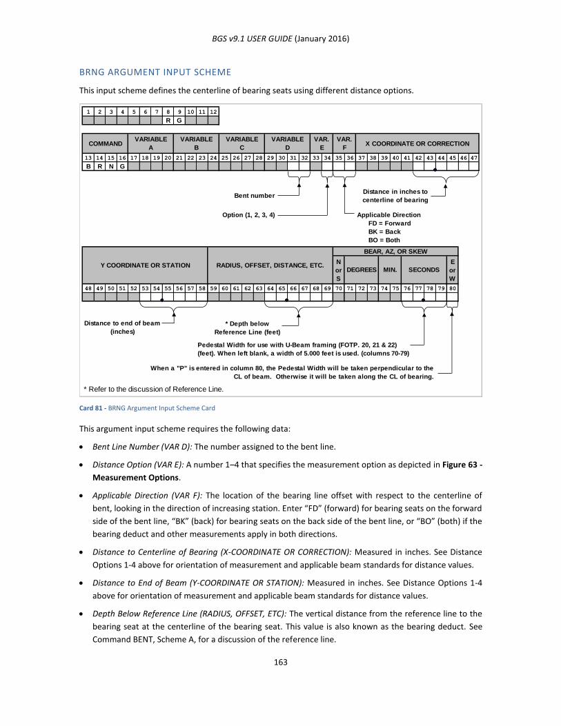
BGS v9.1 USER GUIDE (January 2016)
163
BRNG ARGUMENT INPUT SCHEME
This input scheme defines the centerline of bearing seats using different distance options.
Card 81 - BRNG Argument Input Scheme Card
This argument input scheme requires the following data:
Bent Line Number (VAR D): The number assigned to the bent line.
Distance Option (VAR E): A number 1–4 that specifies the measurement option as depicted in Figure 63 -
Measurement Options.
Applicable Direction (VAR F): The location of the bearing line offset with respect to the centerline of
bent, looking in the direction of increasing station. Enter “FD” (forward) for bearing seats on the forward
side of the bent line, “BK” (back) for bearing seats on the back side of the bent line, or “BO” (both) if the
bearing deduct and other measurements apply in both directions.
Distance to Centerline of Bearing (X-COORDINATE OR CORRECTION): Measured in inches. See Distance
Options 1-4 above for orientation of measurement and applicable beam standards for distance values.
Distance to End of Beam (Y-COORDINATE OR STATION): Measured in inches. See Distance Options 1-4
above for orientation of measurement and applicable beam standards for distance values.
Depth Below Reference Line (RADIUS, OFFSET, ETC): The vertical distance from the reference line to the
bearing seat at the centerline of the bearing seat. This value is also known as the bearing deduct. See
Command BENT, Scheme A, for a discussion of the reference line.
1 2 3 4 5 6 7 8 9 10 11 12
R G
13 14 15 16 17 18 19 20 21 22 23 24 25 26 27 28 29 30 31 32 33 34 35 36 37 38 39 40 41 42 43 44 45 46 47
B R N G
Bent numberDistance in inches to
centerline of bearing
Option (1, 2, 3, 4) Applicable Direction
FD = Forward
BK = Back
BO = Both
N
or
S
E
or
W
48 49 50 51 52 53 54 55 56 57 58 59 60 61 62 63 64 65 66 67 68 69 70 71 72 73 74 75 76 77 78 79 80
* Depth below
Reference Line (feet)
* Refer to the discussion of Reference Line.
COMMAND
SECONDSMIN.DEGREES
BEAR, AZ, OR SKEW
RADIUS, OFFSET, DISTANCE, ETC.Y COORDINATE OR STATION
When a "P" is entered in column 80, the Pedestal Width will be taken perpendicular to the
CL of beam. Otherwise it will be taken along the CL of bearing.
Pedestal Width for use with U-Beam framing (FOTP. 20, 21 & 22)
(feet). When left blank, a width of 5.000 feet is used. (columns 70-79)
X COORDINATE OR CORRECTIONVAR.
F
VAR.
E
VARIABLE
D
VARIABLE
C
VARIABLE
B
VARIABLE
A
Distance to end of beam
(inches)
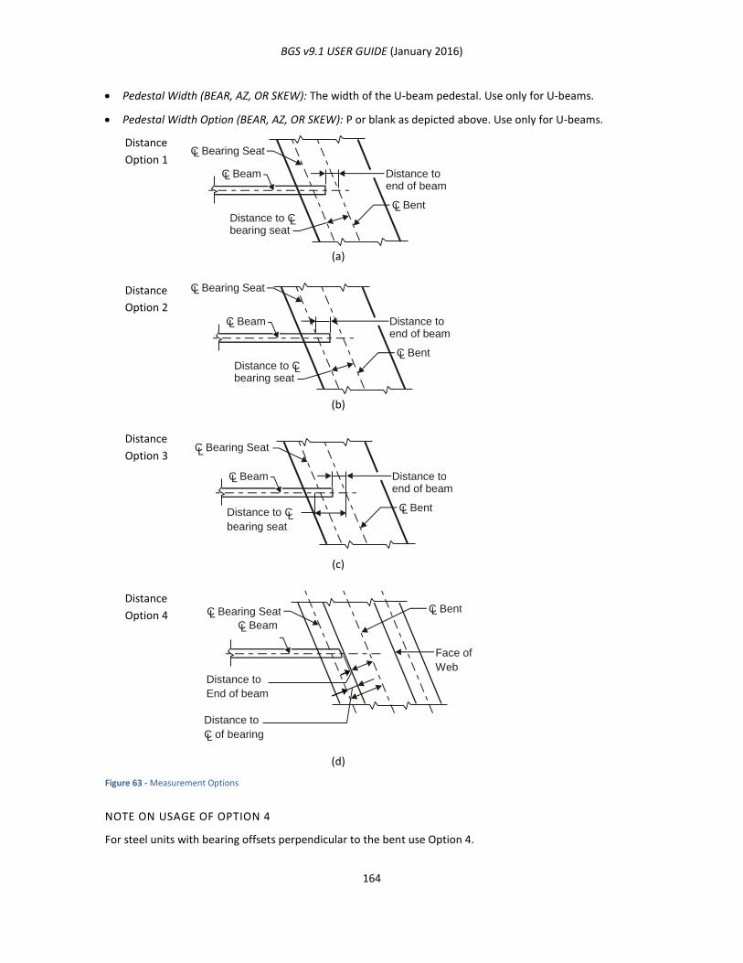
BGS v9.1 USER GUIDE (January 2016)
164
Pedestal Width (BEAR, AZ, OR SKEW): The width of the U-beam pedestal. Use only for U-beams.
Pedestal Width Option (BEAR, AZ, OR SKEW): P or blank as depicted above. Use only for U-beams.
Distance
Option 1
(a)
Distance
Option 2
(b)
Distance
Option 3
(c)
Distance
Option 4
(d)
Figure 63 - Measurement Options
NOTE ON USAGE OF OPTION 4
For steel units with bearing offsets perpendicular to the bent use Option 4.
C Bearing Seat
C Beam
C Bent
Distance toend of beam
Distance to Cbearing seat
L
L
L
L
C Bearing Seat
C Beam
C Bent
Distance toend of beam
Distance to Cbearing seat
L
L
L
L
C Beam
C Bent
Distance to end of beam
Distance to C
bearing seat
L
L L
C Bearing Seat
L
C Bearing Seat C Beam
C Bent
Face of
Web Distance to End of beam
Distance to C of bearing
L L
L
L
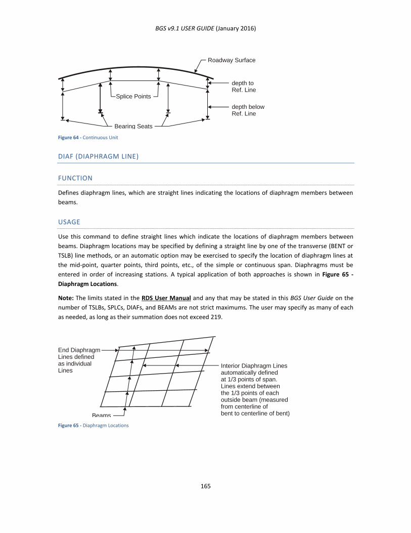
BGS v9.1 USER GUIDE (January 2016)
165
Figure 64 - Continuous Unit
DIAF (DIAPHRAGM LINE)
FUNCTION
Defines diaphragm lines, which are straight lines indicating the locations of diaphragm members between
beams.
USAGE
Use this command to define straight lines which indicate the locations of diaphragm members between
beams. Diaphragm locations may be specified by defining a straight line by one of the transverse (BENT or
TSLB) line methods, or an automatic option may be exercised to specify the location of diaphragm lines at
the mid-point, quarter points, third points, etc., of the simple or continuous span. Diaphragms must be
entered in order of increasing stations. A typical application of both approaches is shown in Figure 65 -
Diaphragm Locations.
Note: The limits stated in the RDS User Manual and any that may be stated in this BGS User Guide on the
number of TSLBs, SPLCs, DIAFs, and BEAMs are not strict maximums. The user may specify as many of each
as needed, as long as their summation does not exceed 219.
Figure 65 - Diaphragm Locations
Roadway Surface
depth toRef. Line
depth belowRef. Line
Bearing Seats
Splice Points
End DiaphragmLines definedas individualLines
Beams
Interior Diaphragm Linesautomatically definedat 1/3 points of span.Lines extend betweenthe 1/3 points of eachoutside beam (measuredfrom centerline ofbent to centerline of bent)
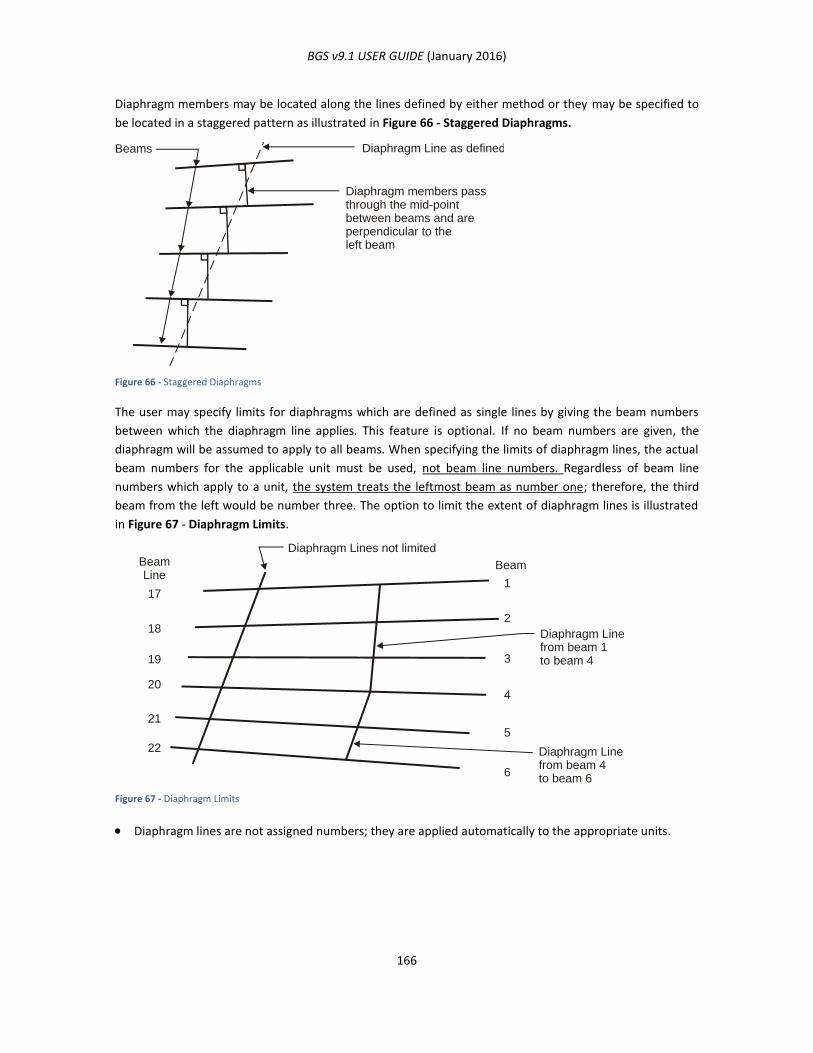
BGS v9.1 USER GUIDE (January 2016)
166
Diaphragm members may be located along the lines defined by either method or they may be specified to
be located in a staggered pattern as illustrated in Figure 66 - Staggered Diaphragms.
Figure 66 - Staggered Diaphragms
The user may specify limits for diaphragms which are defined as single lines by giving the beam numbers
between which the diaphragm line applies. This feature is optional. If no beam numbers are given, the
diaphragm will be assumed to apply to all beams. When specifying the limits of diaphragm lines, the actual
beam numbers for the applicable unit must be used, not beam line numbers. Regardless of beam line
numbers which apply to a unit, the system treats the leftmost beam as number one; therefore, the third
beam from the left would be number three. The option to limit the extent of diaphragm lines is illustrated
in Figure 67 - Diaphragm Limits.
Figure 67 - Diaphragm Limits
Diaphragm lines are not assigned numbers; they are applied automatically to the appropriate units.
Beams Diaphragm Line as defined
Diaphragm members passthrough the mid-pointbetween beams and areperpendicular to theleft beam
BeamLine
Beam
171
182
19 3
204
215
22
6
Diaphragm Lines not limited
Diaphragm Linefrom beam 1to beam 4
Diaphragm Linefrom beam 4to beam 6
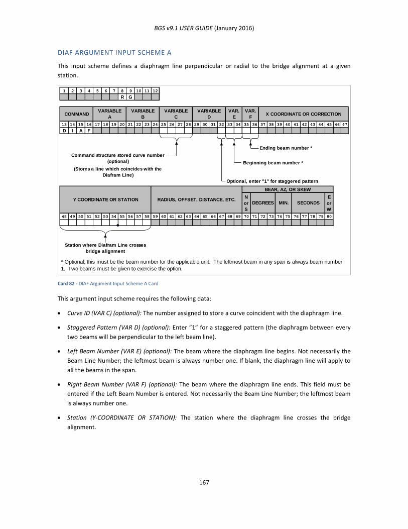
BGS v9.1 USER GUIDE (January 2016)
167
DIAF ARGUMENT INPUT SCHEME A
This input scheme defines a diaphragm line perpendicular or radial to the bridge alignment at a given
station.
Card 82 - DIAF Argument Input Scheme A Card
This argument input scheme requires the following data:
Curve ID (VAR C) (optional): The number assigned to store a curve coincident with the diaphragm line.
Staggered Pattern (VAR D) (optional): Enter “1” for a staggered pattern (the diaphragm between every
two beams will be perpendicular to the left beam line).
Left Beam Number (VAR E) (optional): The beam where the diaphragm line begins. Not necessarily the
Beam Line Number; the leftmost beam is always number one. If blank, the diaphragm line will apply to
all the beams in the span.
Right Beam Number (VAR F) (optional): The beam where the diaphragm line ends. This field must be
entered if the Left Beam Number is entered. Not necessarily the Beam Line Number; the leftmost beam
is always number one.
Station (Y-COORDINATE OR STATION): The station where the diaphragm line crosses the bridge
alignment.
1 2 3 4 5 6 7 8 9 10 11 12
R G
13 14 15 16 17 18 19 20 21 22 23 24 25 26 27 28 29 30 31 32 33 34 35 36 37 38 39 40 41 42 43 44 45 46 47
D I A F
Ending beam number *
Beginning beam number *
(Stores a line which coincides with the
Diafram Line)
Optional, enter "1" for staggered pattern
N
or
S
E
or
W
48 49 50 51 52 53 54 55 56 57 58 59 60 61 62 63 64 65 66 67 68 69 70 71 72 73 74 75 76 77 78 79 80
VARIABLE
D
VAR.
E
VAR.
FX COORDINATE OR CORRECTIONCOMMAND
VARIABLE
A
VARIABLE
B
VARIABLE
C
Command structure stored curve number
(optional)
* Optional; this must be the beam number for the applicable unit. The leftmost beam in any span is always beam number
1. Two beams must be given to exercise the option.
Y COORDINATE OR STATION RADIUS, OFFSET, DISTANCE, ETC.
BEAR, AZ, OR SKEW
DEGREES MIN. SECONDS
Station where Diafram Line crosses
bridge alignment
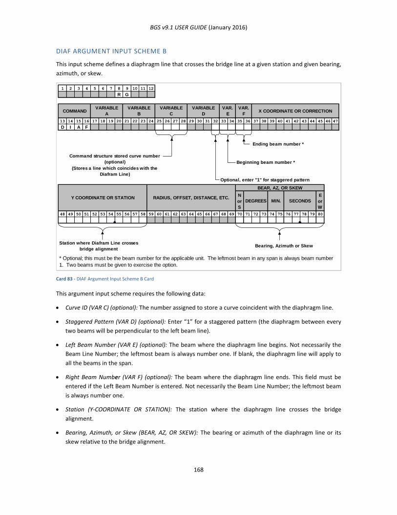
BGS v9.1 USER GUIDE (January 2016)
168
DIAF ARGUMENT INPUT SCHEME B
This input scheme defines a diaphragm line that crosses the bridge line at a given station and given bearing,
azimuth, or skew.
Card 83 - DIAF Argument Input Scheme B Card
This argument input scheme requires the following data:
Curve ID (VAR C) (optional): The number assigned to store a curve coincident with the diaphragm line.
Staggered Pattern (VAR D) (optional): Enter “1” for a staggered pattern (the diaphragm between every
two beams will be perpendicular to the left beam line).
Left Beam Number (VAR E) (optional): The beam where the diaphragm line begins. Not necessarily the
Beam Line Number; the leftmost beam is always number one. If blank, the diaphragm line will apply to
all the beams in the span.
Right Beam Number (VAR F) (optional): The beam where the diaphragm line ends. This field must be
entered if the Left Beam Number is entered. Not necessarily the Beam Line Number; the leftmost beam
is always number one.
Station (Y-COORDINATE OR STATION): The station where the diaphragm line crosses the bridge
alignment.
Bearing, Azimuth, or Skew (BEAR, AZ, OR SKEW): The bearing or azimuth of the diaphragm line or its
skew relative to the bridge alignment.
1 2 3 4 5 6 7 8 9 10 11 12
R G
13 14 15 16 17 18 19 20 21 22 23 24 25 26 27 28 29 30 31 32 33 34 35 36 37 38 39 40 41 42 43 44 45 46 47
D I A F
Ending beam number *
Beginning beam number *
(Stores a line which coincides with the
Diafram Line)
Optional, enter "1" for staggered pattern
N
or
S
E
or
W
48 49 50 51 52 53 54 55 56 57 58 59 60 61 62 63 64 65 66 67 68 69 70 71 72 73 74 75 76 77 78 79 80
Station where Diafram Line crosses
bridge alignmentBearing, Azimuth or Skew
* Optional; this must be the beam number for the applicable unit. The leftmost beam in any span is always beam number
1. Two beams must be given to exercise the option.
VARIABLE
A
VARIABLE
B
VARIABLE
C
VARIABLE
D
VAR.
E
VAR.
FX COORDINATE OR CORRECTIONCOMMAND
SECONDSY COORDINATE OR STATION
Command structure stored curve number
(optional)
MIN.DEGREES
BEAR, AZ, OR SKEW
RADIUS, OFFSET, DISTANCE, ETC.
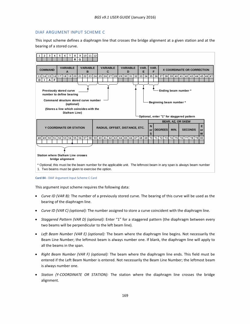
BGS v9.1 USER GUIDE (January 2016)
169
DIAF ARGUMENT INPUT SCHEME C
This input scheme defines a diaphragm line that crosses the bridge alignment at a given station and at the
bearing of a stored curve.
Card 84 - DIAF Argument Input Scheme C Card
This argument input scheme requires the following data:
Curve ID (VAR B): The number of a previously stored curve. The bearing of this curve will be used as the
bearing of the diaphragm line.
Curve ID (VAR C) (optional): The number assigned to store a curve coincident with the diaphragm line.
Staggered Pattern (VAR D) (optional): Enter “1” for a staggered pattern (the diaphragm between every
two beams will be perpendicular to the left beam line).
Left Beam Number (VAR E) (optional): The beam where the diaphragm line begins. Not necessarily the
Beam Line Number; the leftmost beam is always number one. If blank, the diaphragm line will apply to
all the beams in the span.
Right Beam Number (VAR F) (optional): The beam where the diaphragm line ends. This field must be
entered if the Left Beam Number is entered. Not necessarily the Beam Line Number; the leftmost beam
is always number one.
Station (Y-COORDINATE OR STATION): The station where the diaphragm line crosses the bridge
alignment.
1 2 3 4 5 6 7 8 9 10 11 12
R G
13 14 15 16 17 18 19 20 21 22 23 24 25 26 27 28 29 30 31 32 33 34 35 36 37 38 39 40 41 42 43 44 45 46 47
D I A F
Ending beam number *
Beginning beam number *
(Stores a line which coincides with the
Diafram Line)
Optional, enter "1" for staggered pattern
N
or
S
E
or
W
48 49 50 51 52 53 54 55 56 57 58 59 60 61 62 63 64 65 66 67 68 69 70 71 72 73 74 75 76 77 78 79 80
Station where Diafram Line crosses
bridge alignment
VARIABLE
D
VAR.
E
VAR.
FX COORDINATE OR CORRECTIONCOMMAND
VARIABLE
B
VARIABLE
C
VARIABLE
A
Command structure stored curve number
(optional)
* Optional; this must be the beam number for the applicable unit. The leftmost beam in any span is always beam number
1. Two beams must be given to exercise the option.
Previously stored curve
number to define bearing
SECONDSMIN.DEGREES
BEAR, AZ, OR SKEW
RADIUS, OFFSET, DISTANCE, ETC.Y COORDINATE OR STATION
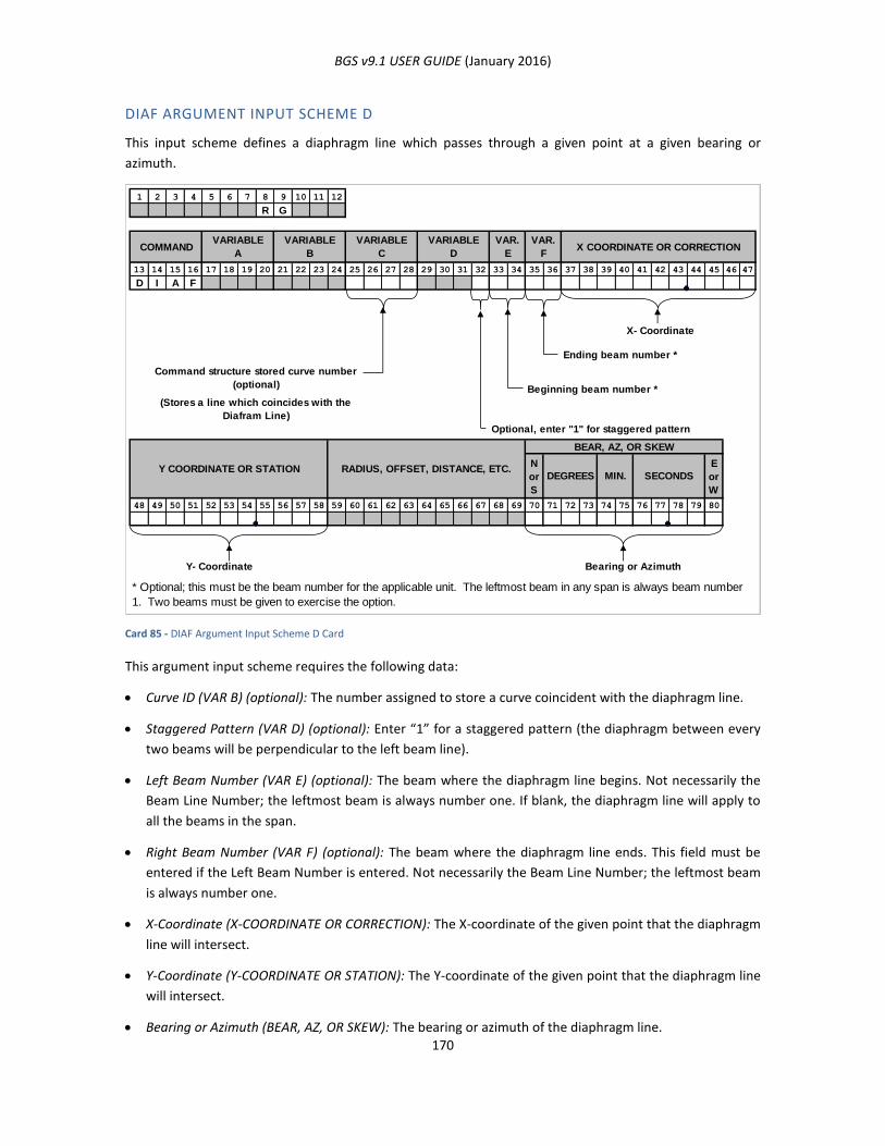
BGS v9.1 USER GUIDE (January 2016)
170
DIAF ARGUMENT INPUT SCHEME D
This input scheme defines a diaphragm line which passes through a given point at a given bearing or
azimuth.
Card 85 - DIAF Argument Input Scheme D Card
This argument input scheme requires the following data:
Curve ID (VAR B) (optional): The number assigned to store a curve coincident with the diaphragm line.
Staggered Pattern (VAR D) (optional): Enter “1” for a staggered pattern (the diaphragm between every
two beams will be perpendicular to the left beam line).
Left Beam Number (VAR E) (optional): The beam where the diaphragm line begins. Not necessarily the
Beam Line Number; the leftmost beam is always number one. If blank, the diaphragm line will apply to
all the beams in the span.
Right Beam Number (VAR F) (optional): The beam where the diaphragm line ends. This field must be
entered if the Left Beam Number is entered. Not necessarily the Beam Line Number; the leftmost beam
is always number one.
X-Coordinate (X-COORDINATE OR CORRECTION): The X-coordinate of the given point that the diaphragm
line will intersect.
Y-Coordinate (Y-COORDINATE OR STATION): The Y-coordinate of the given point that the diaphragm line
will intersect.
Bearing or Azimuth (BEAR, AZ, OR SKEW): The bearing or azimuth of the diaphragm line.
1 2 3 4 5 6 7 8 9 10 11 12
R G
13 14 15 16 17 18 19 20 21 22 23 24 25 26 27 28 29 30 31 32 33 34 35 36 37 38 39 40 41 42 43 44 45 46 47
D I A F
X- Coordinate
Ending beam number *
Beginning beam number *
(Stores a line which coincides with the
Diafram Line)
Optional, enter "1" for staggered pattern
N
or
S
E
or
W
48 49 50 51 52 53 54 55 56 57 58 59 60 61 62 63 64 65 66 67 68 69 70 71 72 73 74 75 76 77 78 79 80
Y- Coordinate Bearing or Azimuth
VARIABLE
D
VAR.
E
VAR.
FX COORDINATE OR CORRECTIONCOMMAND
VARIABLE
A
VARIABLE
B
VARIABLE
C
Command structure stored curve number
(optional)
* Optional; this must be the beam number for the applicable unit. The leftmost beam in any span is always beam number
1. Two beams must be given to exercise the option.
DEGREES MIN. SECONDS
BEAR, AZ, OR SKEW
RADIUS, OFFSET, DISTANCE, ETC.Y COORDINATE OR STATION
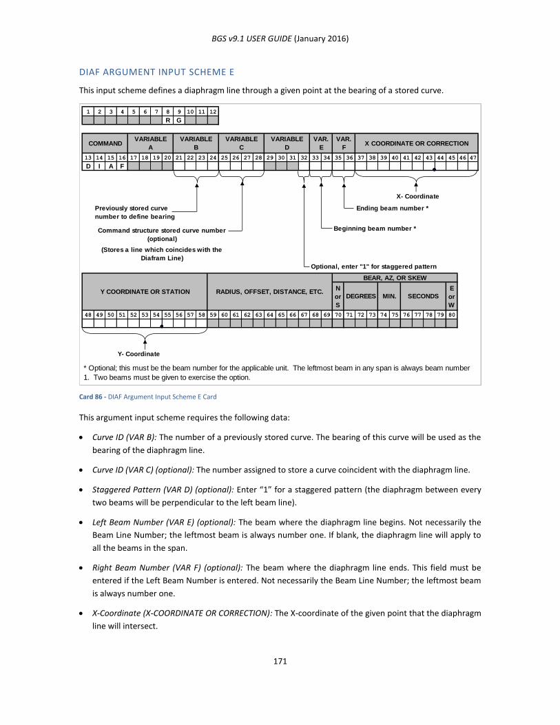
BGS v9.1 USER GUIDE (January 2016)
171
DIAF ARGUMENT INPUT SCHEME E
This input scheme defines a diaphragm line through a given point at the bearing of a stored curve.
Card 86 - DIAF Argument Input Scheme E Card
This argument input scheme requires the following data:
Curve ID (VAR B): The number of a previously stored curve. The bearing of this curve will be used as the
bearing of the diaphragm line.
Curve ID (VAR C) (optional): The number assigned to store a curve coincident with the diaphragm line.
Staggered Pattern (VAR D) (optional): Enter “1” for a staggered pattern (the diaphragm between every
two beams will be perpendicular to the left beam line).
Left Beam Number (VAR E) (optional): The beam where the diaphragm line begins. Not necessarily the
Beam Line Number; the leftmost beam is always number one. If blank, the diaphragm line will apply to
all the beams in the span.
Right Beam Number (VAR F) (optional): The beam where the diaphragm line ends. This field must be
entered if the Left Beam Number is entered. Not necessarily the Beam Line Number; the leftmost beam
is always number one.
X-Coordinate (X-COORDINATE OR CORRECTION): The X-coordinate of the given point that the diaphragm
line will intersect.
1 2 3 4 5 6 7 8 9 10 11 12
R G
13 14 15 16 17 18 19 20 21 22 23 24 25 26 27 28 29 30 31 32 33 34 35 36 37 38 39 40 41 42 43 44 45 46 47
D I A F
X- Coordinate
Ending beam number *
Beginning beam number *
(Stores a line which coincides with the
Diafram Line)
Optional, enter "1" for staggered pattern
N
or
S
E
or
W
48 49 50 51 52 53 54 55 56 57 58 59 60 61 62 63 64 65 66 67 68 69 70 71 72 73 74 75 76 77 78 79 80
Y- Coordinate
VARIABLE
D
VAR.
E
VAR.
FX COORDINATE OR CORRECTIONCOMMAND
VARIABLE
B
VARIABLE
C
VARIABLE
A
Command structure stored curve number
(optional)
* Optional; this must be the beam number for the applicable unit. The leftmost beam in any span is always beam number
1. Two beams must be given to exercise the option.
Previously stored curve
number to define bearing
SECONDSMIN.DEGREES
BEAR, AZ, OR SKEW
RADIUS, OFFSET, DISTANCE, ETC.Y COORDINATE OR STATION
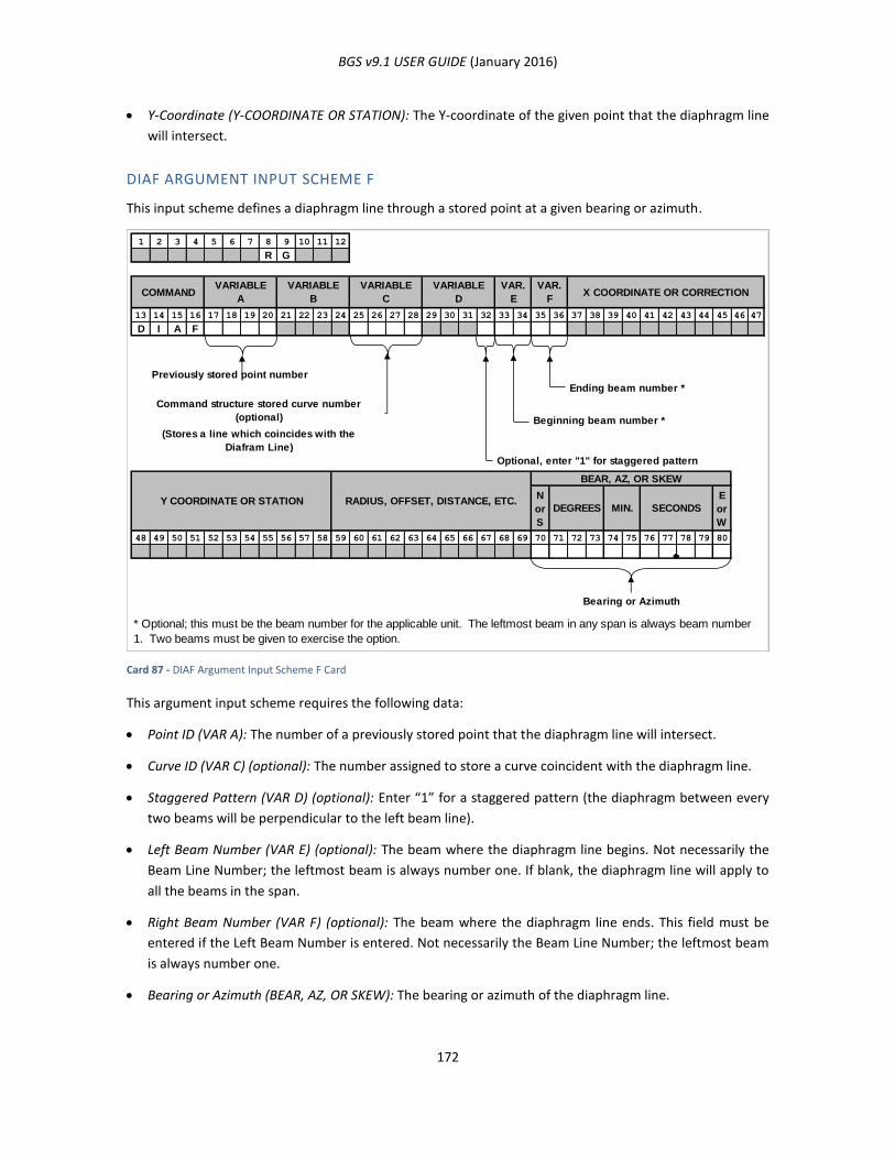
BGS v9.1 USER GUIDE (January 2016)
172
Y-Coordinate (Y-COORDINATE OR STATION): The Y-coordinate of the given point that the diaphragm line
will intersect.
DIAF ARGUMENT INPUT SCHEME F
This input scheme defines a diaphragm line through a stored point at a given bearing or azimuth.
Card 87 - DIAF Argument Input Scheme F Card
This argument input scheme requires the following data:
Point ID (VAR A): The number of a previously stored point that the diaphragm line will intersect.
Curve ID (VAR C) (optional): The number assigned to store a curve coincident with the diaphragm line.
Staggered Pattern (VAR D) (optional): Enter “1” for a staggered pattern (the diaphragm between every
two beams will be perpendicular to the left beam line).
Left Beam Number (VAR E) (optional): The beam where the diaphragm line begins. Not necessarily the
Beam Line Number; the leftmost beam is always number one. If blank, the diaphragm line will apply to
all the beams in the span.
Right Beam Number (VAR F) (optional): The beam where the diaphragm line ends. This field must be
entered if the Left Beam Number is entered. Not necessarily the Beam Line Number; the leftmost beam
is always number one.
Bearing or Azimuth (BEAR, AZ, OR SKEW): The bearing or azimuth of the diaphragm line.
1 2 3 4 5 6 7 8 9 10 11 12
R G
13 14 15 16 17 18 19 20 21 22 23 24 25 26 27 28 29 30 31 32 33 34 35 36 37 38 39 40 41 42 43 44 45 46 47
D I A F
Previously stored point number
Ending beam number *
Beginning beam number *
(Stores a line which coincides with the
Diafram Line)
Optional, enter "1" for staggered pattern
N
or
S
E
or
W
48 49 50 51 52 53 54 55 56 57 58 59 60 61 62 63 64 65 66 67 68 69 70 71 72 73 74 75 76 77 78 79 80
Bearing or Azimuth
VARIABLE
D
VAR.
E
VAR.
FX COORDINATE OR CORRECTIONCOMMAND
VARIABLE
A
VARIABLE
B
VARIABLE
C
Command structure stored curve number
(optional)
* Optional; this must be the beam number for the applicable unit. The leftmost beam in any span is always beam number
1. Two beams must be given to exercise the option.
SECONDSMIN.DEGREES
BEAR, AZ, OR SKEW
RADIUS, OFFSET, DISTANCE, ETC.Y COORDINATE OR STATION
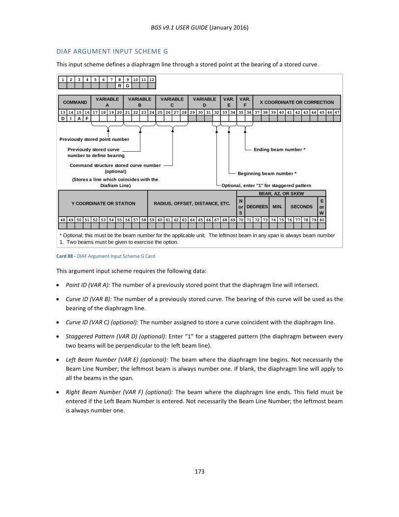
BGS v9.1 USER GUIDE (January 2016)
173
DIAF ARGUMENT INPUT SCHEME G
This input scheme defines a diaphragm line through a stored point at the bearing of a stored curve.
Card 88 - DIAF Argument Input Scheme G Card
This argument input scheme requires the following data:
Point ID (VAR A): The number of a previously stored point that the diaphragm line will intersect.
Curve ID (VAR B): The number of a previously stored curve. The bearing of this curve will be used as the
bearing of the diaphragm line.
Curve ID (VAR C) (optional): The number assigned to store a curve coincident with the diaphragm line.
Staggered Pattern (VAR D) (optional): Enter “1” for a staggered pattern (the diaphragm between every
two beams will be perpendicular to the left beam line).
Left Beam Number (VAR E) (optional): The beam where the diaphragm line begins. Not necessarily the
Beam Line Number; the leftmost beam is always number one. If blank, the diaphragm line will apply to
all the beams in the span.
Right Beam Number (VAR F) (optional): The beam where the diaphragm line ends. This field must be
entered if the Left Beam Number is entered. Not necessarily the Beam Line Number; the leftmost beam
is always number one.
1 2 3 4 5 6 7 8 9 10 11 12
R G
13 14 15 16 17 18 19 20 21 22 23 24 25 26 27 28 29 30 31 32 33 34 35 36 37 38 39 40 41 42 43 44 45 46 47
D I A F
Previously stored point number
Ending beam number *
Beginning beam number *
(Stores a line which coincides with the
Diafram Line) Optional, enter "1" for staggered pattern
N
or
S
E
or
W
48 49 50 51 52 53 54 55 56 57 58 59 60 61 62 63 64 65 66 67 68 69 70 71 72 73 74 75 76 77 78 79 80
VARIABLE
C
VARIABLE
B
VARIABLE
ACOMMAND X COORDINATE OR CORRECTION
VAR.
F
VAR.
E
VARIABLE
D
Command structure stored curve number
(optional)
* Optional; this must be the beam number for the applicable unit. The leftmost beam in any span is always beam number
1. Two beams must be given to exercise the option.
Previously stored curve
number to define bearing
SECONDSMIN.DEGREESRADIUS, OFFSET, DISTANCE, ETC.Y COORDINATE OR STATION
BEAR, AZ, OR SKEW
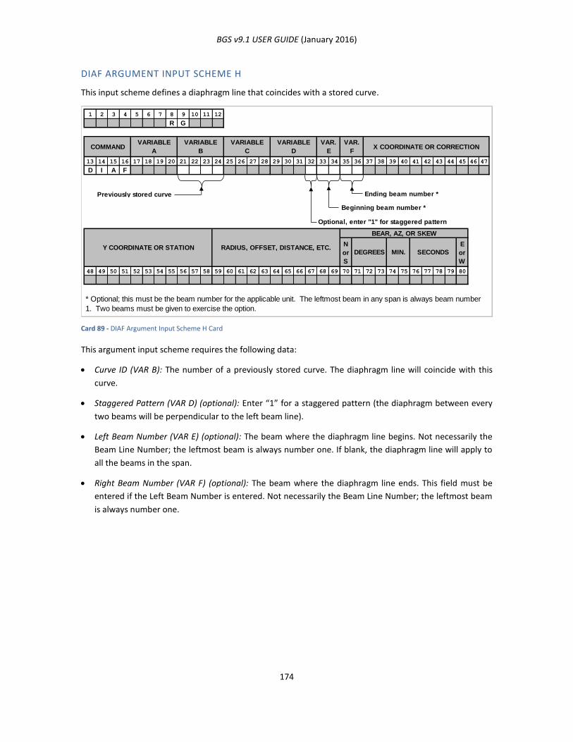
BGS v9.1 USER GUIDE (January 2016)
174
DIAF ARGUMENT INPUT SCHEME H
This input scheme defines a diaphragm line that coincides with a stored curve.
Card 89 - DIAF Argument Input Scheme H Card
This argument input scheme requires the following data:
Curve ID (VAR B): The number of a previously stored curve. The diaphragm line will coincide with this
curve.
Staggered Pattern (VAR D) (optional): Enter “1” for a staggered pattern (the diaphragm between every
two beams will be perpendicular to the left beam line).
Left Beam Number (VAR E) (optional): The beam where the diaphragm line begins. Not necessarily the
Beam Line Number; the leftmost beam is always number one. If blank, the diaphragm line will apply to
all the beams in the span.
Right Beam Number (VAR F) (optional): The beam where the diaphragm line ends. This field must be
entered if the Left Beam Number is entered. Not necessarily the Beam Line Number; the leftmost beam
is always number one.
1 2 3 4 5 6 7 8 9 10 11 12
R G
13 14 15 16 17 18 19 20 21 22 23 24 25 26 27 28 29 30 31 32 33 34 35 36 37 38 39 40 41 42 43 44 45 46 47
D I A F
Ending beam number *
Beginning beam number *
Optional, enter "1" for staggered pattern
N
or
S
E
or
W
48 49 50 51 52 53 54 55 56 57 58 59 60 61 62 63 64 65 66 67 68 69 70 71 72 73 74 75 76 77 78 79 80
VARIABLE
C
VARIABLE
B
VARIABLE
ACOMMAND X COORDINATE OR CORRECTION
VAR.
F
VAR.
E
VARIABLE
D
* Optional; this must be the beam number for the applicable unit. The leftmost beam in any span is always beam number
1. Two beams must be given to exercise the option.
Previously stored curve
Y COORDINATE OR STATION RADIUS, OFFSET, DISTANCE, ETC.DEGREES MIN.
BEAR, AZ, OR SKEW
SECONDS
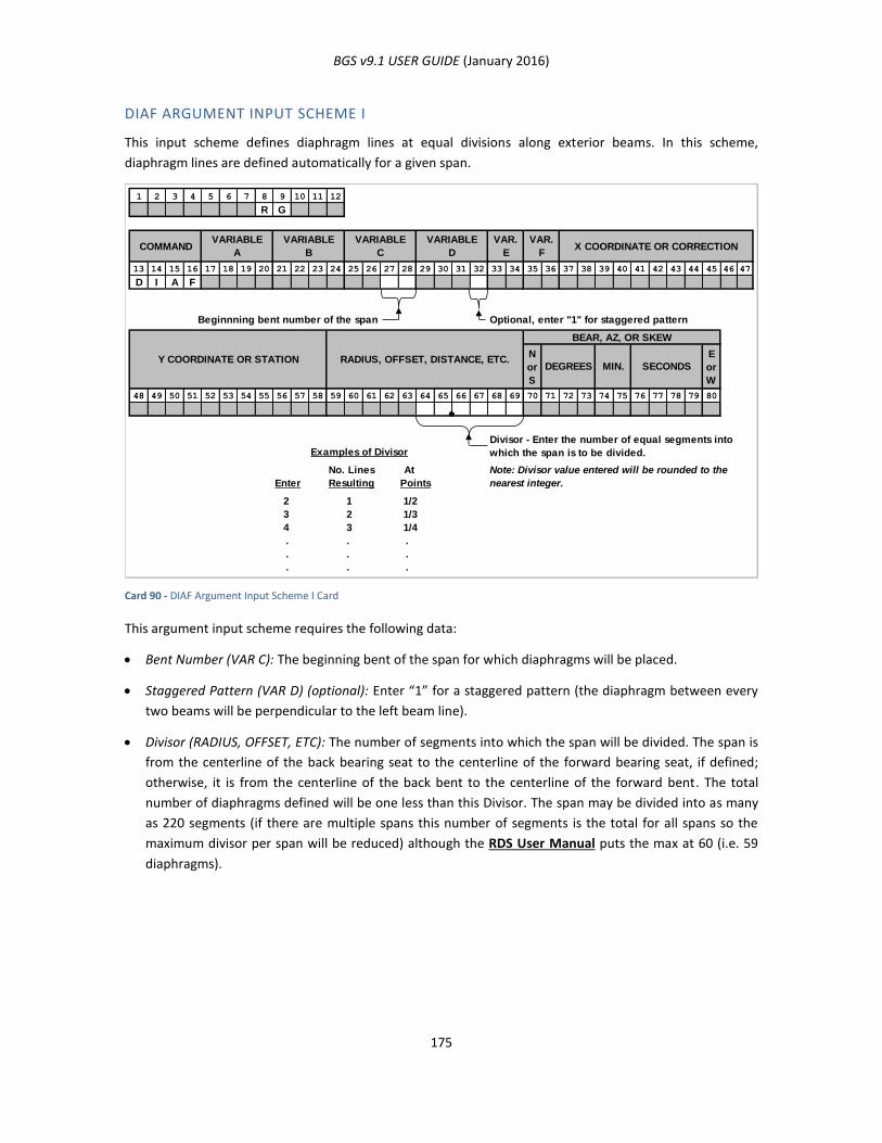
BGS v9.1 USER GUIDE (January 2016)
175
DIAF ARGUMENT INPUT SCHEME I
This input scheme defines diaphragm lines at equal divisions along exterior beams. In this scheme,
diaphragm lines are defined automatically for a given span.
Card 90 - DIAF Argument Input Scheme I Card
This argument input scheme requires the following data:
Bent Number (VAR C): The beginning bent of the span for which diaphragms will be placed.
Staggered Pattern (VAR D) (optional): Enter “1” for a staggered pattern (the diaphragm between every
two beams will be perpendicular to the left beam line).
Divisor (RADIUS, OFFSET, ETC): The number of segments into which the span will be divided. The span is
from the centerline of the back bearing seat to the centerline of the forward bearing seat, if defined;
otherwise, it is from the centerline of the back bent to the centerline of the forward bent. The total
number of diaphragms defined will be one less than this Divisor. The span may be divided into as many
as 220 segments (if there are multiple spans this number of segments is the total for all spans so the
maximum divisor per span will be reduced) although the RDS User Manual puts the max at 60 (i.e. 59
diaphragms).
1 2 3 4 5 6 7 8 9 10 11 12
R G
13 14 15 16 17 18 19 20 21 22 23 24 25 26 27 28 29 30 31 32 33 34 35 36 37 38 39 40 41 42 43 44 45 46 47
D I A F
Beginnning bent number of the span Optional, enter "1" for staggered pattern
N
or
S
E
or
W
48 49 50 51 52 53 54 55 56 57 58 59 60 61 62 63 64 65 66 67 68 69 70 71 72 73 74 75 76 77 78 79 80
Examples of Divisor
No. Lines At
Enter Resulting Points
2 1
3 2
4 3
. . .
. . .
. . .
MIN.DEGREES
BEAR, AZ, OR SKEW
COMMANDVARIABLE
A
VARIABLE
B
VARIABLE
C
RADIUS, OFFSET, DISTANCE, ETC.Y COORDINATE OR STATION
VARIABLE
D
VAR.
E
VAR.
FX COORDINATE OR CORRECTION
SECONDS
1/2
1/3
1/4
Divisor - Enter the number of equal segments into
which the span is to be divided.
Note: Divisor value entered will be rounded to the
nearest integer.
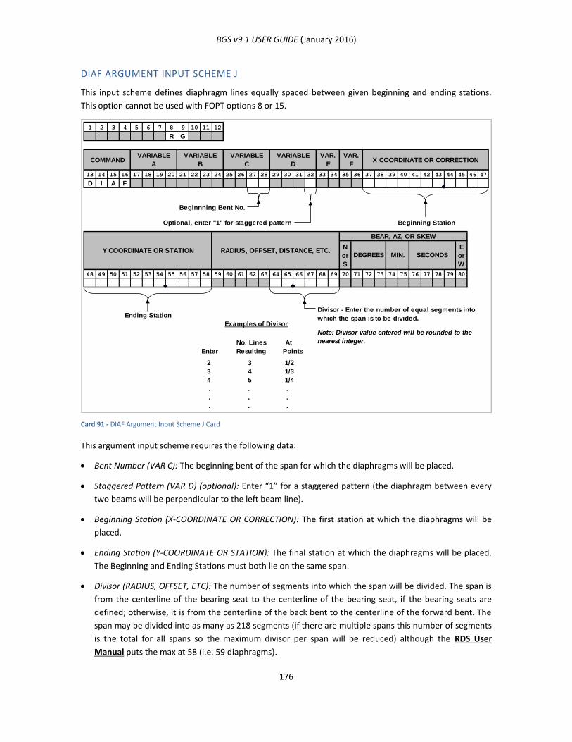
BGS v9.1 USER GUIDE (January 2016)
176
DIAF ARGUMENT INPUT SCHEME J
This input scheme defines diaphragm lines equally spaced between given beginning and ending stations.
This option cannot be used with FOPT options 8 or 15.
Card 91 - DIAF Argument Input Scheme J Card
This argument input scheme requires the following data:
Bent Number (VAR C): The beginning bent of the span for which the diaphragms will be placed.
Staggered Pattern (VAR D) (optional): Enter “1” for a staggered pattern (the diaphragm between every
two beams will be perpendicular to the left beam line).
Beginning Station (X-COORDINATE OR CORRECTION): The first station at which the diaphragms will be
placed.
Ending Station (Y-COORDINATE OR STATION): The final station at which the diaphragms will be placed.
The Beginning and Ending Stations must both lie on the same span.
Divisor (RADIUS, OFFSET, ETC): The number of segments into which the span will be divided. The span is
from the centerline of the bearing seat to the centerline of the bearing seat, if the bearing seats are
defined; otherwise, it is from the centerline of the back bent to the centerline of the forward bent. The
span may be divided into as many as 218 segments (if there are multiple spans this number of segments
is the total for all spans so the maximum divisor per span will be reduced) although the RDS User
Manual puts the max at 58 (i.e. 59 diaphragms).
1 2 3 4 5 6 7 8 9 10 11 12
R G
13 14 15 16 17 18 19 20 21 22 23 24 25 26 27 28 29 30 31 32 33 34 35 36 37 38 39 40 41 42 43 44 45 46 47
D I A F
Beginnning Bent No.
Optional, enter "1" for staggered pattern Beginning Station
N
or
S
E
or
W
48 49 50 51 52 53 54 55 56 57 58 59 60 61 62 63 64 65 66 67 68 69 70 71 72 73 74 75 76 77 78 79 80
Ending Station
Examples of Divisor
No. Lines At
Enter Resulting Points
2 3
3 4
4 5
. . .
. . .
. . .
MIN.DEGREES
BEAR, AZ, OR SKEW
COMMANDVARIABLE
A
VARIABLE
B
VARIABLE
C
RADIUS, OFFSET, DISTANCE, ETC.Y COORDINATE OR STATION
VARIABLE
D
VAR.
E
VAR.
FX COORDINATE OR CORRECTION
SECONDS
1/2
1/3
1/4
Divisor - Enter the number of equal segments into
which the span is to be divided.
Note: Divisor value entered will be rounded to the
nearest integer.
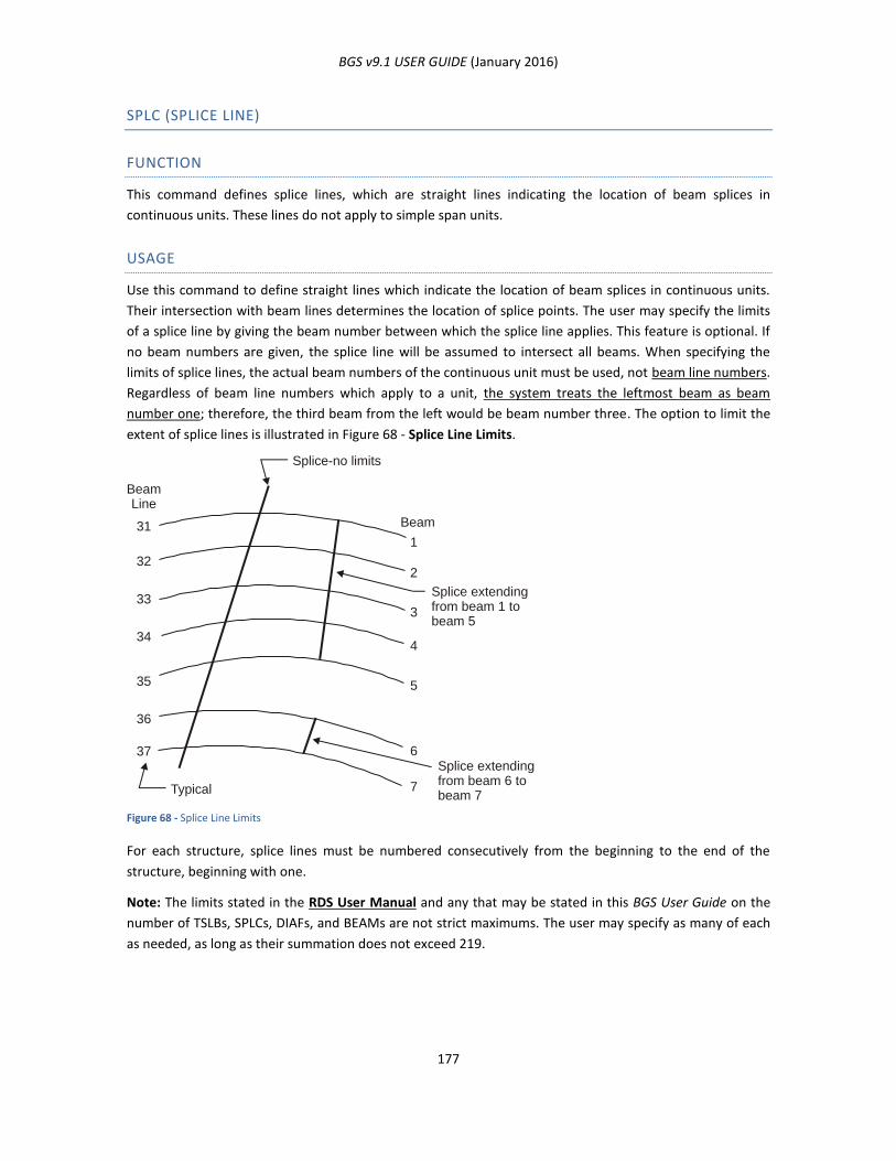
BGS v9.1 USER GUIDE (January 2016)
177
SPLC (SPLICE LINE)
FUNCTION
This command defines splice lines, which are straight lines indicating the location of beam splices in
continuous units. These lines do not apply to simple span units.
USAGE
Use this command to define straight lines which indicate the location of beam splices in continuous units.
Their intersection with beam lines determines the location of splice points. The user may specify the limits
of a splice line by giving the beam number between which the splice line applies. This feature is optional. If
no beam numbers are given, the splice line will be assumed to intersect all beams. When specifying the
limits of splice lines, the actual beam numbers of the continuous unit must be used, not beam line numbers.
Regardless of beam line numbers which apply to a unit, the system treats the leftmost beam as beam
number one; therefore, the third beam from the left would be beam number three. The option to limit the
extent of splice lines is illustrated in Figure 68 - Splice Line Limits.
Figure 68 - Splice Line Limits
For each structure, splice lines must be numbered consecutively from the beginning to the end of the
structure, beginning with one.
Note: The limits stated in the RDS User Manual and any that may be stated in this BGS User Guide on the
number of TSLBs, SPLCs, DIAFs, and BEAMs are not strict maximums. The user may specify as many of each
as needed, as long as their summation does not exceed 219.
BeamLine
Beam31
1
322
33
34
3
35
4
36
5
37 6
7
Splice-no limits
Typical
Splice extendingfrom beam 1 to beam 5
Splice extendingfrom beam 6 tobeam 7
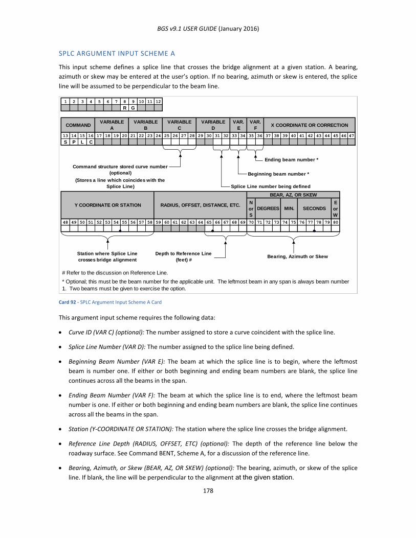
BGS v9.1 USER GUIDE (January 2016)
178
SPLC ARGUMENT INPUT SCHEME A
This input scheme defines a splice line that crosses the bridge alignment at a given station. A bearing,
azimuth or skew may be entered at the user’s option. If no bearing, azimuth or skew is entered, the splice
line will be assumed to be perpendicular to the beam line.
Card 92 - SPLC Argument Input Scheme A Card
This argument input scheme requires the following data:
Curve ID (VAR C) (optional): The number assigned to store a curve coincident with the splice line.
Splice Line Number (VAR D): The number assigned to the splice line being defined.
Beginning Beam Number (VAR E): The beam at which the splice line is to begin, where the leftmost
beam is number one. If either or both beginning and ending beam numbers are blank, the splice line
continues across all the beams in the span.
Ending Beam Number (VAR F): The beam at which the splice line is to end, where the leftmost beam
number is one. If either or both beginning and ending beam numbers are blank, the splice line continues
across all the beams in the span.
Station (Y-COORDINATE OR STATION): The station where the splice line crosses the bridge alignment.
Reference Line Depth (RADIUS, OFFSET, ETC) (optional): The depth of the reference line below the
roadway surface. See Command BENT, Scheme A, for a discussion of the reference line.
Bearing, Azimuth, or Skew (BEAR, AZ, OR SKEW) (optional): The bearing, azimuth, or skew of the splice
line. If blank, the line will be perpendicular to the alignment at the given station.
1 2 3 4 5 6 7 8 9 10 11 12
R G
13 14 15 16 17 18 19 20 21 22 23 24 25 26 27 28 29 30 31 32 33 34 35 36 37 38 39 40 41 42 43 44 45 46 47
S P L C
Ending beam number *
Beginning beam number *
(Stores a line which coincides with the
Splice Line) Splice Line number being defined
N
or
S
E
or
W
48 49 50 51 52 53 54 55 56 57 58 59 60 61 62 63 64 65 66 67 68 69 70 71 72 73 74 75 76 77 78 79 80
Station where Splice Line
crosses bridge alignment
Depth to Reference Line
(feet) #Bearing, Azimuth or Skew
# Refer to the discussion on Reference Line.
RADIUS, OFFSET, DISTANCE, ETC.
* Optional; this must be the beam number for the applicable unit. The leftmost beam in any span is always beam number
1. Two beams must be given to exercise the option.
X COORDINATE OR CORRECTIONVAR.
F
VAR.
E
VARIABLE
D
VARIABLE
C
VARIABLE
B
VARIABLE
ACOMMAND
SECONDSY COORDINATE OR STATION
Command structure stored curve number
(optional)
MIN.DEGREES
BEAR, AZ, OR SKEW
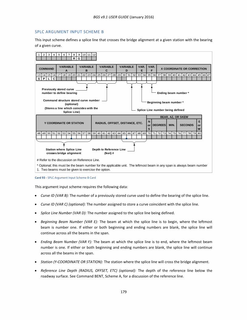
BGS v9.1 USER GUIDE (January 2016)
179
SPLC ARGUMENT INPUT SCHEME B
This input scheme defines a splice line that crosses the bridge alignment at a given station with the bearing
of a given curve.
Card 93 - SPLC Argument Input Scheme B Card
This argument input scheme requires the following data:
Curve ID (VAR B): The number of a previously stored curve used to define the bearing of the splice line.
Curve ID (VAR C) (optional): The number assigned to store a curve coincident with the splice line.
Splice Line Number (VAR D): The number assigned to the splice line being defined.
Beginning Beam Number (VAR E): The beam at which the splice line is to begin, where the leftmost
beam is number one. If either or both beginning and ending numbers are blank, the splice line will
continue across all the beams in the span.
Ending Beam Number (VAR F): The beam at which the splice line is to end, where the leftmost beam
number is one. If either or both beginning and ending numbers are blank, the splice line will continue
across all the beams in the span.
Station (Y-COORDINATE OR STATION): The station where the splice line will cross the bridge alignment.
Reference Line Depth (RADIUS, OFFSET, ETC) (optional): The depth of the reference line below the
roadway surface. See Command BENT, Scheme A, for a discussion of the reference line.
1 2 3 4 5 6 7 8 9 10 11 12
R G
13 14 15 16 17 18 19 20 21 22 23 24 25 26 27 28 29 30 31 32 33 34 35 36 37 38 39 40 41 42 43 44 45 46 47
S P L C
Ending beam number *
Beginning beam number *
(Stores a line which coincides with the
Splice Line)Splice Line number being defined
N
or
S
E
or
W
48 49 50 51 52 53 54 55 56 57 58 59 60 61 62 63 64 65 66 67 68 69 70 71 72 73 74 75 76 77 78 79 80
Station where Splice Line
crosses bridge alignment
Depth to Reference Line
(feet) #
# Refer to the discussion on Reference Line.
RADIUS, OFFSET, DISTANCE, ETC.
* Optional; this must be the beam number for the applicable unit. The leftmost beam in any span is always beam number
1. Two beams must be given to exercise the option.
X COORDINATE OR CORRECTIONVAR.
F
VAR.
E
VARIABLE
D
VARIABLE
C
VARIABLE
B
VARIABLE
ACOMMAND
SECONDSY COORDINATE OR STATION
Command structure stored curve number
(optional)
Previously stored curve
number to define bearing
MIN.DEGREES
BEAR, AZ, OR SKEW
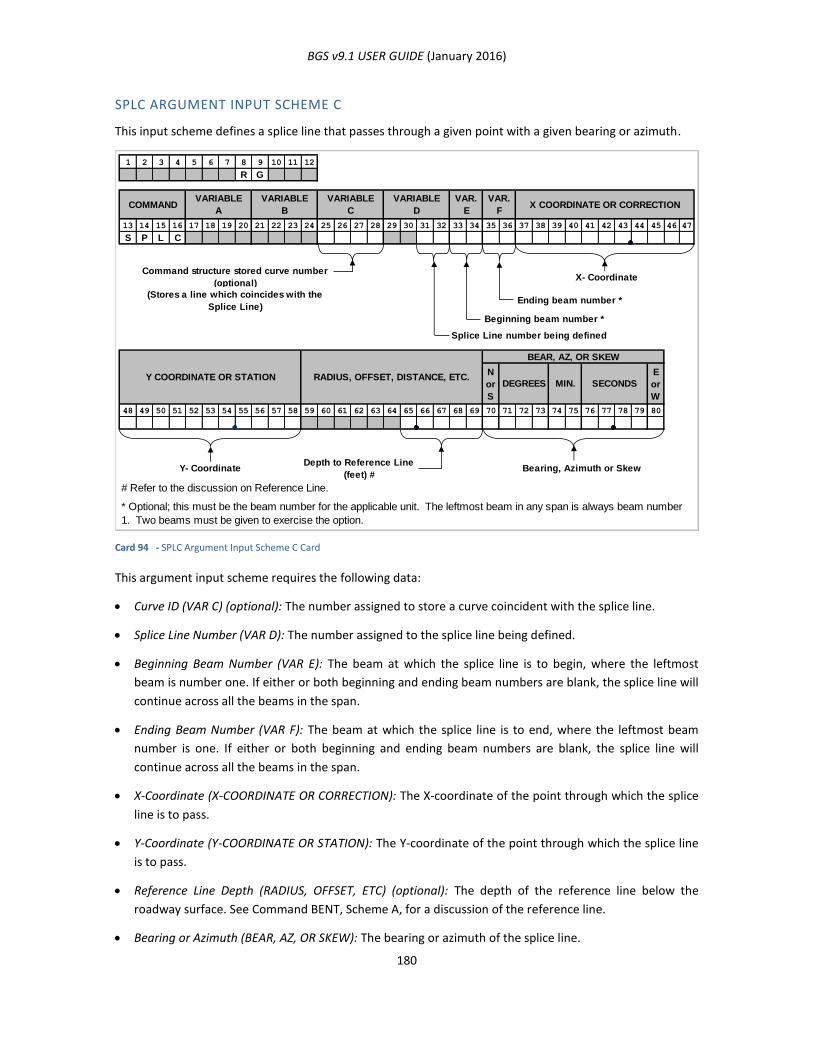
BGS v9.1 USER GUIDE (January 2016)
180
SPLC ARGUMENT INPUT SCHEME C
This input scheme defines a splice line that passes through a given point with a given bearing or azimuth.
Card 94 - SPLC Argument Input Scheme C Card
This argument input scheme requires the following data:
Curve ID (VAR C) (optional): The number assigned to store a curve coincident with the splice line.
Splice Line Number (VAR D): The number assigned to the splice line being defined.
Beginning Beam Number (VAR E): The beam at which the splice line is to begin, where the leftmost
beam is number one. If either or both beginning and ending beam numbers are blank, the splice line will
continue across all the beams in the span.
Ending Beam Number (VAR F): The beam at which the splice line is to end, where the leftmost beam
number is one. If either or both beginning and ending beam numbers are blank, the splice line will
continue across all the beams in the span.
X-Coordinate (X-COORDINATE OR CORRECTION): The X-coordinate of the point through which the splice
line is to pass.
Y-Coordinate (Y-COORDINATE OR STATION): The Y-coordinate of the point through which the splice line
is to pass.
Reference Line Depth (RADIUS, OFFSET, ETC) (optional): The depth of the reference line below the
roadway surface. See Command BENT, Scheme A, for a discussion of the reference line.
Bearing or Azimuth (BEAR, AZ, OR SKEW): The bearing or azimuth of the splice line.
1 2 3 4 5 6 7 8 9 10 11 12
R G
13 14 15 16 17 18 19 20 21 22 23 24 25 26 27 28 29 30 31 32 33 34 35 36 37 38 39 40 41 42 43 44 45 46 47
S P L C
X- Coordinate
(Stores a line which coincides with the
Splice Line)Ending beam number *
Beginning beam number *
Splice Line number being defined
N
or
S
E
or
W
48 49 50 51 52 53 54 55 56 57 58 59 60 61 62 63 64 65 66 67 68 69 70 71 72 73 74 75 76 77 78 79 80
Y- CoordinateDepth to Reference Line
(feet) #Bearing, Azimuth or Skew
# Refer to the discussion on Reference Line.
VARIABLE
C
VARIABLE
B
VARIABLE
ACOMMAND X COORDINATE OR CORRECTION
VAR.
F
VAR.
E
VARIABLE
D
Command structure stored curve number
(optional)
* Optional; this must be the beam number for the applicable unit. The leftmost beam in any span is always beam number
1. Two beams must be given to exercise the option.
SECONDSMIN.DEGREES
BEAR, AZ, OR SKEW
RADIUS, OFFSET, DISTANCE, ETC.Y COORDINATE OR STATION
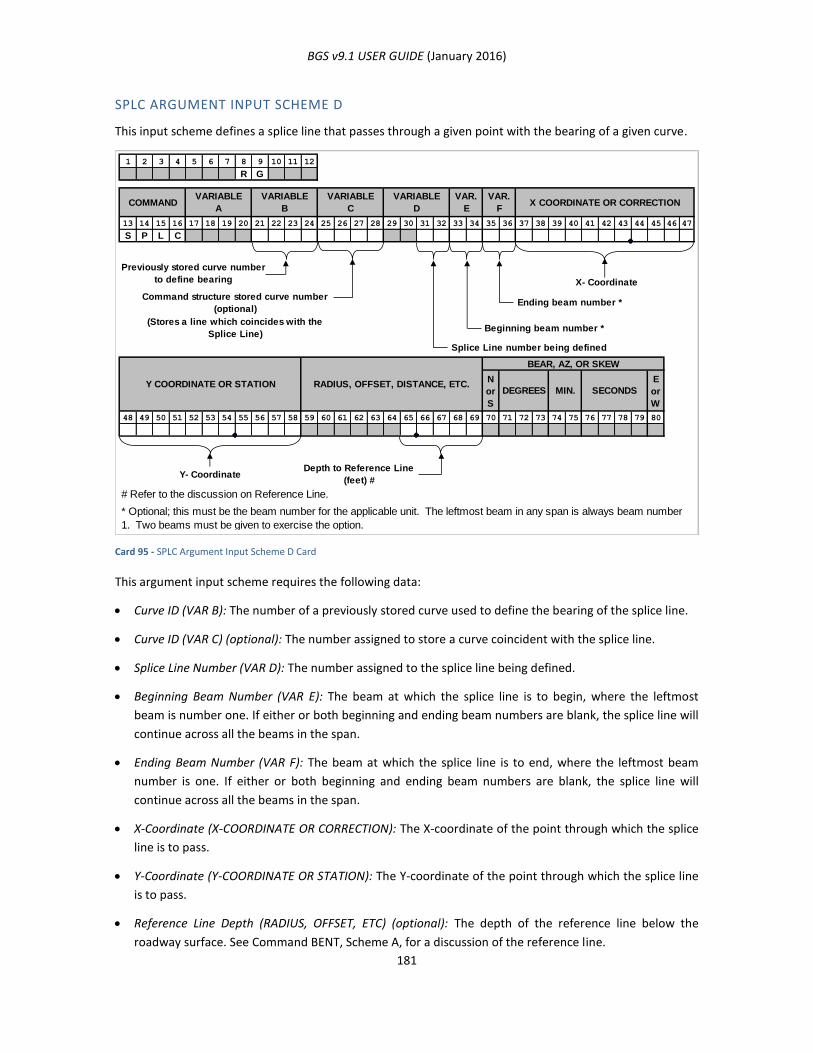
BGS v9.1 USER GUIDE (January 2016)
181
SPLC ARGUMENT INPUT SCHEME D
This input scheme defines a splice line that passes through a given point with the bearing of a given curve.
Card 95 - SPLC Argument Input Scheme D Card
This argument input scheme requires the following data:
Curve ID (VAR B): The number of a previously stored curve used to define the bearing of the splice line.
Curve ID (VAR C) (optional): The number assigned to store a curve coincident with the splice line.
Splice Line Number (VAR D): The number assigned to the splice line being defined.
Beginning Beam Number (VAR E): The beam at which the splice line is to begin, where the leftmost
beam is number one. If either or both beginning and ending beam numbers are blank, the splice line will
continue across all the beams in the span.
Ending Beam Number (VAR F): The beam at which the splice line is to end, where the leftmost beam
number is one. If either or both beginning and ending beam numbers are blank, the splice line will
continue across all the beams in the span.
X-Coordinate (X-COORDINATE OR CORRECTION): The X-coordinate of the point through which the splice
line is to pass.
Y-Coordinate (Y-COORDINATE OR STATION): The Y-coordinate of the point through which the splice line
is to pass.
Reference Line Depth (RADIUS, OFFSET, ETC) (optional): The depth of the reference line below the
roadway surface. See Command BENT, Scheme A, for a discussion of the reference line.
1 2 3 4 5 6 7 8 9 10 11 12
R G
13 14 15 16 17 18 19 20 21 22 23 24 25 26 27 28 29 30 31 32 33 34 35 36 37 38 39 40 41 42 43 44 45 46 47
S P L C
X- Coordinate
Ending beam number *
(Stores a line which coincides with the
Splice Line)Beginning beam number *
Splice Line number being defined
N
or
S
E
or
W
48 49 50 51 52 53 54 55 56 57 58 59 60 61 62 63 64 65 66 67 68 69 70 71 72 73 74 75 76 77 78 79 80
Y- CoordinateDepth to Reference Line
(feet) #
# Refer to the discussion on Reference Line.
BEAR, AZ, OR SKEW
Previously stored curve number
to define bearing
* Optional; this must be the beam number for the applicable unit. The leftmost beam in any span is always beam number
1. Two beams must be given to exercise the option.
COMMANDVARIABLE
A
VARIABLE
B
VARIABLE
C
VARIABLE
D
VAR.
E
VAR.
F
RADIUS, OFFSET, DISTANCE, ETC.Y COORDINATE OR STATION
Command structure stored curve number
(optional)
X COORDINATE OR CORRECTION
SECONDSMIN.DEGREES
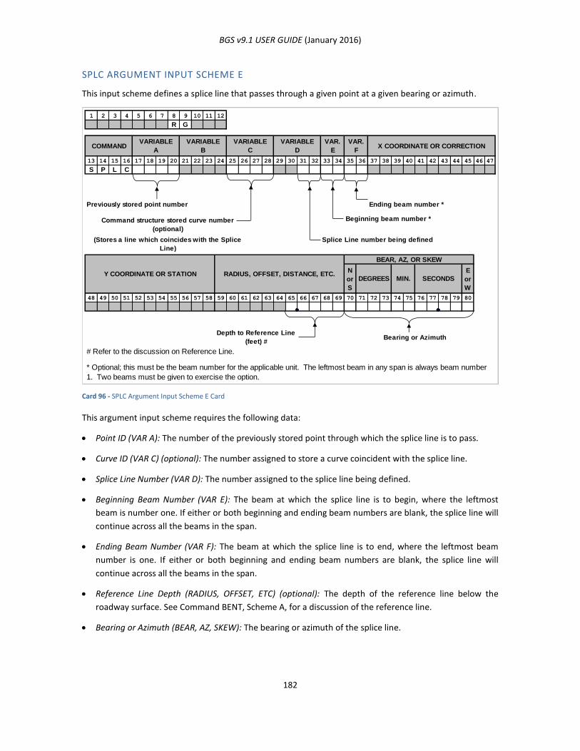
BGS v9.1 USER GUIDE (January 2016)
182
SPLC ARGUMENT INPUT SCHEME E
This input scheme defines a splice line that passes through a given point at a given bearing or azimuth.
Card 96 - SPLC Argument Input Scheme E Card
This argument input scheme requires the following data:
Point ID (VAR A): The number of the previously stored point through which the splice line is to pass.
Curve ID (VAR C) (optional): The number assigned to store a curve coincident with the splice line.
Splice Line Number (VAR D): The number assigned to the splice line being defined.
Beginning Beam Number (VAR E): The beam at which the splice line is to begin, where the leftmost
beam is number one. If either or both beginning and ending beam numbers are blank, the splice line will
continue across all the beams in the span.
Ending Beam Number (VAR F): The beam at which the splice line is to end, where the leftmost beam
number is one. If either or both beginning and ending beam numbers are blank, the splice line will
continue across all the beams in the span.
Reference Line Depth (RADIUS, OFFSET, ETC) (optional): The depth of the reference line below the
roadway surface. See Command BENT, Scheme A, for a discussion of the reference line.
Bearing or Azimuth (BEAR, AZ, SKEW): The bearing or azimuth of the splice line.
1 2 3 4 5 6 7 8 9 10 11 12
R G
13 14 15 16 17 18 19 20 21 22 23 24 25 26 27 28 29 30 31 32 33 34 35 36 37 38 39 40 41 42 43 44 45 46 47
S P L C
Previously stored point number Ending beam number *
Beginning beam number *
Splice Line number being defined
N
or
S
E
or
W
48 49 50 51 52 53 54 55 56 57 58 59 60 61 62 63 64 65 66 67 68 69 70 71 72 73 74 75 76 77 78 79 80
Depth to Reference Line
(feet) #Bearing or Azimuth
# Refer to the discussion on Reference Line.
Command structure stored curve number
(optional)
(Stores a line which coincides with the Splice
Line)
* Optional; this must be the beam number for the applicable unit. The leftmost beam in any span is always beam number
1. Two beams must be given to exercise the option.
COMMANDVARIABLE
A
VARIABLE
B
VARIABLE
C
VARIABLE
D
VAR.
E
VAR.
F
RADIUS, OFFSET, DISTANCE, ETC.Y COORDINATE OR STATION
X COORDINATE OR CORRECTION
SECONDSMIN.DEGREES
BEAR, AZ, OR SKEW
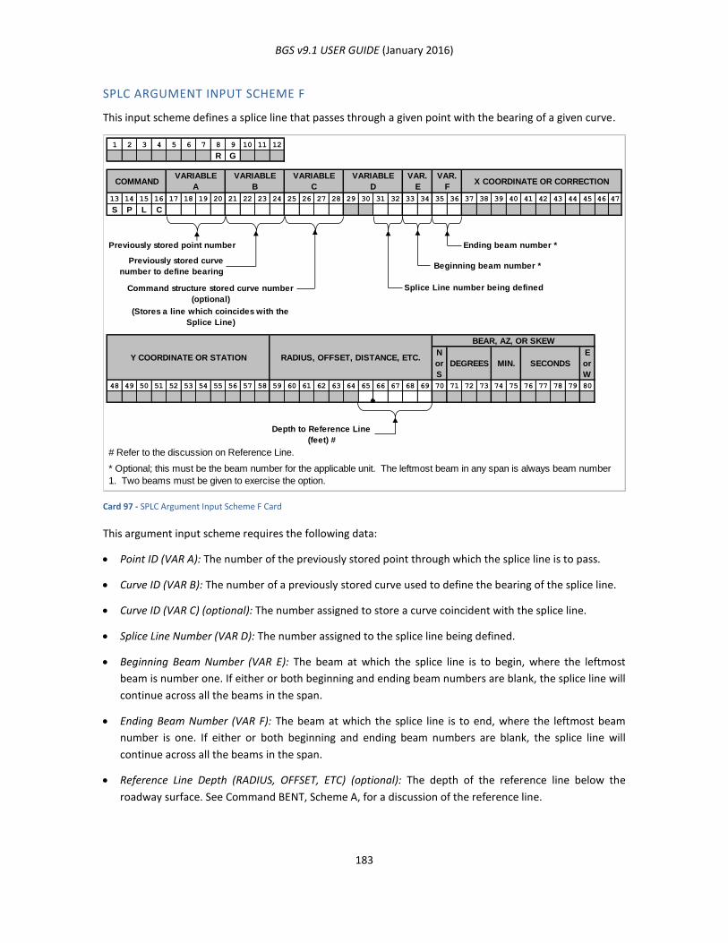
BGS v9.1 USER GUIDE (January 2016)
183
SPLC ARGUMENT INPUT SCHEME F
This input scheme defines a splice line that passes through a given point with the bearing of a given curve.
Card 97 - SPLC Argument Input Scheme F Card
This argument input scheme requires the following data:
Point ID (VAR A): The number of the previously stored point through which the splice line is to pass.
Curve ID (VAR B): The number of a previously stored curve used to define the bearing of the splice line.
Curve ID (VAR C) (optional): The number assigned to store a curve coincident with the splice line.
Splice Line Number (VAR D): The number assigned to the splice line being defined.
Beginning Beam Number (VAR E): The beam at which the splice line is to begin, where the leftmost
beam is number one. If either or both beginning and ending beam numbers are blank, the splice line will
continue across all the beams in the span.
Ending Beam Number (VAR F): The beam at which the splice line is to end, where the leftmost beam
number is one. If either or both beginning and ending beam numbers are blank, the splice line will
continue across all the beams in the span.
Reference Line Depth (RADIUS, OFFSET, ETC) (optional): The depth of the reference line below the
roadway surface. See Command BENT, Scheme A, for a discussion of the reference line.
1 2 3 4 5 6 7 8 9 10 11 12
R G
13 14 15 16 17 18 19 20 21 22 23 24 25 26 27 28 29 30 31 32 33 34 35 36 37 38 39 40 41 42 43 44 45 46 47
S P L C
Previously stored point number Ending beam number *
Beginning beam number *
Splice Line number being defined
(Stores a line which coincides with the
Splice Line)
N
or
S
E
or
W
48 49 50 51 52 53 54 55 56 57 58 59 60 61 62 63 64 65 66 67 68 69 70 71 72 73 74 75 76 77 78 79 80
Depth to Reference Line
(feet) #
# Refer to the discussion on Reference Line.
Command structure stored curve number
(optional)
Previously stored curve
number to define bearing
* Optional; this must be the beam number for the applicable unit. The leftmost beam in any span is always beam number
1. Two beams must be given to exercise the option.
COMMANDVARIABLE
A
VARIABLE
B
VARIABLE
C
VARIABLE
D
VAR.
E
VAR.
F
RADIUS, OFFSET, DISTANCE, ETC.Y COORDINATE OR STATION
X COORDINATE OR CORRECTION
SECONDSMIN.DEGREES
BEAR, AZ, OR SKEW

BGS v9.1 USER GUIDE (January 2016)
184
SPLC ARGUMENT INPUT SCHEME G
This input scheme defines a splice line coincident with a previously stored curve.
Card 98 - SPLC Argument Input Scheme G Card
This argument input scheme requires the following data:
Curve ID (VAR B): The number of a previously stored curve coincident with the splice line.
Splice Line Number (VAR D): The number assigned to the splice line being defined.
Beginning Beam Number (VAR E): The beam at which the splice line is to begin, where the leftmost
beam is number one. If either or both beginning and ending beam numbers are blank, the splice line will
continue across all the beams in the span.
Ending Beam Number (VAR F): The beam at which the splice line is to end, where the leftmost beam
number is one. If either or both beginning and ending beam numbers are blank, the splice line will
continue across all the beams in the span.
Reference Line Depth (RADIUS, OFFSET, ETC) (optional): The depth of the reference line below the
roadway surface. See Command BENT, Scheme A, for a discussion of the reference line.
1 2 3 4 5 6 7 8 9 10 11 12
R G
13 14 15 16 17 18 19 20 21 22 23 24 25 26 27 28 29 30 31 32 33 34 35 36 37 38 39 40 41 42 43 44 45 46 47
S P L C
Ending beam number *
Beginning beam number *
Splice Line number being defined
N
or
S
E
or
W
48 49 50 51 52 53 54 55 56 57 58 59 60 61 62 63 64 65 66 67 68 69 70 71 72 73 74 75 76 77 78 79 80
Depth to Reference Line
(feet) #
# Refer to the discussion on Reference Line.
Previously stored curve
number which coincides
with Splice Line
* Optional; this must be the beam number for the applicable unit. The leftmost beam in any span is always beam number
1. Two beams must be given to exercise the option.
COMMANDVARIABLE
A
VARIABLE
B
VARIABLE
C
VARIABLE
D
VAR.
E
VAR.
FX COORDINATE OR CORRECTION
RADIUS, OFFSET, DISTANCE, ETC.Y COORDINATE OR STATIONSECONDSMIN.DEGREES
BEAR, AZ, OR SKEW
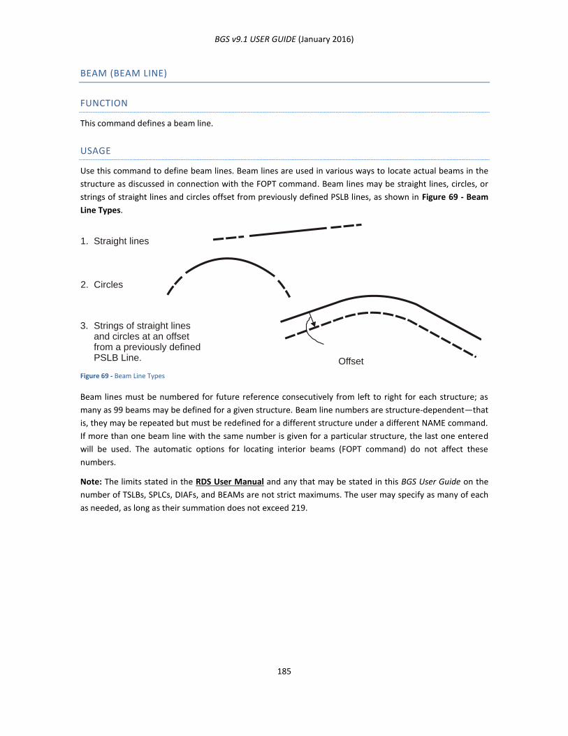
BGS v9.1 USER GUIDE (January 2016)
185
BEAM (BEAM LINE)
FUNCTION
This command defines a beam line.
USAGE
Use this command to define beam lines. Beam lines are used in various ways to locate actual beams in the
structure as discussed in connection with the FOPT command. Beam lines may be straight lines, circles, or
strings of straight lines and circles offset from previously defined PSLB lines, as shown in Figure 69 - Beam
Line Types.
Figure 69 - Beam Line Types
Beam lines must be numbered for future reference consecutively from left to right for each structure; as
many as 99 beams may be defined for a given structure. Beam line numbers are structure-dependent—that
is, they may be repeated but must be redefined for a different structure under a different NAME command.
If more than one beam line with the same number is given for a particular structure, the last one entered
will be used. The automatic options for locating interior beams (FOPT command) do not affect these
numbers.
Note: The limits stated in the RDS User Manual and any that may be stated in this BGS User Guide on the
number of TSLBs, SPLCs, DIAFs, and BEAMs are not strict maximums. The user may specify as many of each
as needed, as long as their summation does not exceed 219.
1. Straight lines
2. Circles
Strings of straight linesand circles at an offsetfrom a previously definedPSLB Line.
3.
Offset
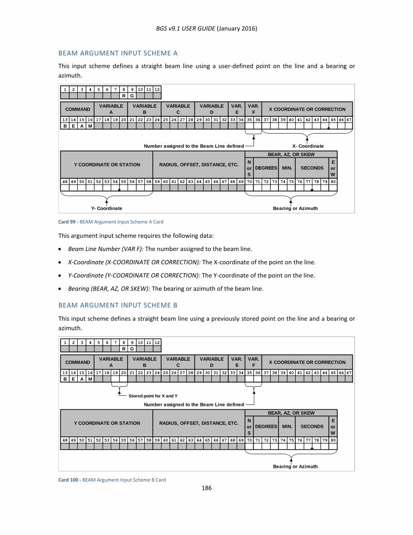
BGS v9.1 USER GUIDE (January 2016)
186
BEAM ARGUMENT INPUT SCHEME A
This input scheme defines a straight beam line using a user-defined point on the line and a bearing or
azimuth.
Card 99 - BEAM Argument Input Scheme A Card
This argument input scheme requires the following data:
Beam Line Number (VAR F): The number assigned to the beam line.
X-Coordinate (X-COORDINATE OR CORRECTION): The X-coordinate of the point on the line.
Y-Coordinate (Y-COORDINATE OR CORRECTION): The Y-coordinate of the point on the line.
Bearing (BEAR, AZ, OR SKEW): The bearing or azimuth of the beam line.
BEAM ARGUMENT INPUT SCHEME B
This input scheme defines a straight beam line using a previously stored point on the line and a bearing or
azimuth.
Card 100 - BEAM Argument Input Scheme B Card
1 2 3 4 5 6 7 8 9 10 11 12
R G
13 14 15 16 17 18 19 20 21 22 23 24 25 26 27 28 29 30 31 32 33 34 35 36 37 38 39 40 41 42 43 44 45 46 47
B E A M
Number assigned to the Beam Line defined X- Coordinate
N
or
S
E
or
W
48 49 50 51 52 53 54 55 56 57 58 59 60 61 62 63 64 65 66 67 68 69 70 71 72 73 74 75 76 77 78 79 80
Y- Coordinate Bearing or Azimuth
SECONDSMIN.DEGREES
BEAR, AZ, OR SKEW
RADIUS, OFFSET, DISTANCE, ETC.Y COORDINATE OR STATION
VARIABLE
C
VARIABLE
B
VARIABLE
ACOMMAND X COORDINATE OR CORRECTION
VAR.
F
VAR.
E
VARIABLE
D
1 2 3 4 5 6 7 8 9 10 11 12
R G
13 14 15 16 17 18 19 20 21 22 23 24 25 26 27 28 29 30 31 32 33 34 35 36 37 38 39 40 41 42 43 44 45 46 47
B E A M
Stored point for X and Y
Number assigned to the Beam Line defined
N
or
S
E
or
W
48 49 50 51 52 53 54 55 56 57 58 59 60 61 62 63 64 65 66 67 68 69 70 71 72 73 74 75 76 77 78 79 80
Bearing or Azimuth
X COORDINATE OR CORRECTIONVAR.
F
VAR.
E
VARIABLE
D
VARIABLE
C
VARIABLE
B
VARIABLE
ACOMMAND
RADIUS, OFFSET, DISTANCE, ETC.Y COORDINATE OR STATIONSECONDSMIN.DEGREES
BEAR, AZ, OR SKEW
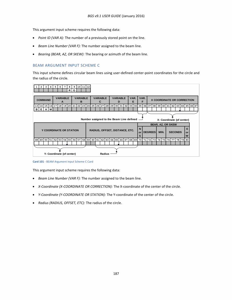
BGS v9.1 USER GUIDE (January 2016)
187
This argument input scheme requires the following data:
Point ID (VAR A): The number of a previously stored point on the line.
Beam Line Number (VAR F): The number assigned to the beam line.
Bearing (BEAR, AZ, OR SKEW): The bearing or azimuth of the beam line.
BEAM ARGUMENT INPUT SCHEME C
This input scheme defines circular beam lines using user-defined center-point coordinates for the circle and
the radius of the circle.
Card 101 - BEAM Argument Input Scheme C Card
This argument input scheme requires the following data:
Beam Line Number (VAR F): The number assigned to the beam line.
X-Coordinate (X-COORDINATE OR CORRECTION): The X-coordinate of the center of the circle.
Y-Coordinate (Y-COORDINATE OR STATION): The Y-coordinate of the center of the circle.
Radius (RADIUS, OFFSET, ETC): The radius of the circle.
1 2 3 4 5 6 7 8 9 10 11 12
R G
13 14 15 16 17 18 19 20 21 22 23 24 25 26 27 28 29 30 31 32 33 34 35 36 37 38 39 40 41 42 43 44 45 46 47
B E A M
Number assigned to the Beam Line defined X- Coordinate (of center)
N
or
S
E
or
W
48 49 50 51 52 53 54 55 56 57 58 59 60 61 62 63 64 65 66 67 68 69 70 71 72 73 74 75 76 77 78 79 80
Y- Coordinate (of center) Radius
COMMANDVARIABLE
A
VARIABLE
B
RADIUS, OFFSET, DISTANCE, ETC.Y COORDINATE OR STATION
X COORDINATE OR CORRECTION
SECONDSMIN.DEGREES
BEAR, AZ, OR SKEW
VARIABLE
C
VARIABLE
D
VAR.
E
VAR.
F

BGS v9.1 USER GUIDE (January 2016)
188
BEAM ARGUMENT INPUT SCHEME D
This input scheme defines circular beam lines using a previously stored center-point for the circle and the
radius of the circle.
Card 102 - BEAM Argument Input Scheme D Card
This argument input scheme requires the following data:
Point ID (VAR A): The number of a previously stored center point of the circle.
Beam Line Number (VAR F): The number assigned to the beam line.
Radius (RADIUS, OFFSET, ETC): The radius of the circle.
BEAM ARGUMENT INPUT SCHEME E
This input scheme defines circular beam lines using a previously stored center-point for the circle and a
previously stored point on the circle.
Card 103 - BEAM Argument Input Scheme E Card
1 2 3 4 5 6 7 8 9 10 11 12
R G
13 14 15 16 17 18 19 20 21 22 23 24 25 26 27 28 29 30 31 32 33 34 35 36 37 38 39 40 41 42 43 44 45 46 47
B E A M
Stored point for the center of the circle
Number assigned to the Beam Line defined
N
or
S
E
or
W
48 49 50 51 52 53 54 55 56 57 58 59 60 61 62 63 64 65 66 67 68 69 70 71 72 73 74 75 76 77 78 79 80
Radius
VARIABLE
D
VAR.
E
VAR.
FX COORDINATE OR CORRECTIONCOMMAND
VARIABLE
A
VARIABLE
B
VARIABLE
C
RADIUS, OFFSET, DISTANCE, ETC.Y COORDINATE OR STATIONSECONDSMIN.DEGREES
BEAR, AZ, OR SKEW
1 2 3 4 5 6 7 8 9 10 11 12
R G
13 14 15 16 17 18 19 20 21 22 23 24 25 26 27 28 29 30 31 32 33 34 35 36 37 38 39 40 41 42 43 44 45 46 47
B E A M
Stored point on the circle
Stored point for the center of the circle
Number assigned to the Beam Line defined
N
or
S
E
or
W
48 49 50 51 52 53 54 55 56 57 58 59 60 61 62 63 64 65 66 67 68 69 70 71 72 73 74 75 76 77 78 79 80
VARIABLE
D
VAR.
E
VAR.
FX COORDINATE OR CORRECTIONCOMMAND
VARIABLE
A
VARIABLE
B
VARIABLE
C
RADIUS, OFFSET, DISTANCE, ETC.Y COORDINATE OR STATIONSECONDSMIN.DEGREES
BEAR, AZ, OR SKEW
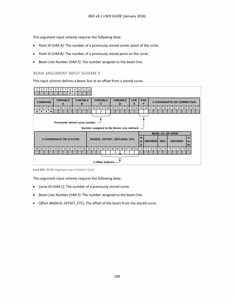
BGS v9.1 USER GUIDE (January 2016)
189
This argument input scheme requires the following data:
Point ID (VAR A): The number of a previously stored center point of the circle.
Point ID (VAR B): The number of a previously stored point on the circle.
Beam Line Number (VAR F): The number assigned to the beam line.
BEAM ARGUMENT INPUT SCHEME F
This input scheme defines a beam line at an offset from a stored curve.
Card 104 - BEAM Argument Input Scheme F Card
This argument input scheme requires the following data:
Curve ID (VAR C): The number of a previously stored curve.
Beam Line Number (VAR F): The number assigned to the beam line.
Offset (RADIUS, OFFSET, ETC): The offset of the beam from the stored curve.
1 2 3 4 5 6 7 8 9 10 11 12
R G
13 14 15 16 17 18 19 20 21 22 23 24 25 26 27 28 29 30 31 32 33 34 35 36 37 38 39 40 41 42 43 44 45 46 47
B E A M
Previously stored curve number
Number assigned to the Beam Line defined
N
or
S
E
or
W
48 49 50 51 52 53 54 55 56 57 58 59 60 61 62 63 64 65 66 67 68 69 70 71 72 73 74 75 76 77 78 79 80
± Offset distance
VARIABLE
D
VAR.
E
VAR.
FX COORDINATE OR CORRECTIONCOMMAND
VARIABLE
A
VARIABLE
B
VARIABLE
C
RADIUS, OFFSET, DISTANCE, ETC.Y COORDINATE OR STATIONSECONDSMIN.DEGREES
BEAR, AZ, OR SKEW
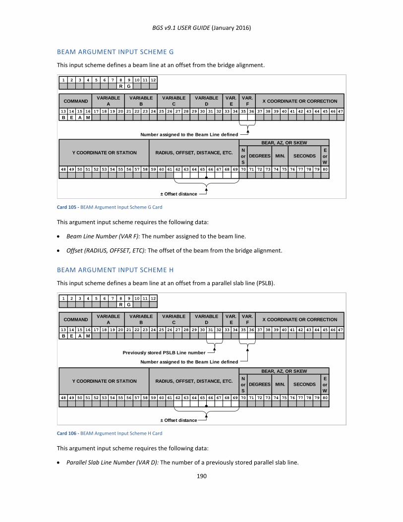
BGS v9.1 USER GUIDE (January 2016)
190
BEAM ARGUMENT INPUT SCHEME G
This input scheme defines a beam line at an offset from the bridge alignment.
Card 105 - BEAM Argument Input Scheme G Card
This argument input scheme requires the following data:
Beam Line Number (VAR F): The number assigned to the beam line.
Offset (RADIUS, OFFSET, ETC): The offset of the beam from the bridge alignment.
BEAM ARGUMENT INPUT SCHEME H
This input scheme defines a beam line at an offset from a parallel slab line (PSLB).
Card 106 - BEAM Argument Input Scheme H Card
This argument input scheme requires the following data:
Parallel Slab Line Number (VAR D): The number of a previously stored parallel slab line.
1 2 3 4 5 6 7 8 9 10 11 12
R G
13 14 15 16 17 18 19 20 21 22 23 24 25 26 27 28 29 30 31 32 33 34 35 36 37 38 39 40 41 42 43 44 45 46 47
B E A M
Number assigned to the Beam Line defined
N
or
S
E
or
W
48 49 50 51 52 53 54 55 56 57 58 59 60 61 62 63 64 65 66 67 68 69 70 71 72 73 74 75 76 77 78 79 80
± Offset distance
VARIABLE
D
VAR.
E
VAR.
FX COORDINATE OR CORRECTIONCOMMAND
VARIABLE
A
VARIABLE
B
VARIABLE
C
RADIUS, OFFSET, DISTANCE, ETC.Y COORDINATE OR STATIONSECONDSMIN.DEGREES
BEAR, AZ, OR SKEW
1 2 3 4 5 6 7 8 9 10 11 12
R G
13 14 15 16 17 18 19 20 21 22 23 24 25 26 27 28 29 30 31 32 33 34 35 36 37 38 39 40 41 42 43 44 45 46 47
B E A M
Previously stored PSLB Line number
Number assigned to the Beam Line defined
N
or
S
E
or
W
48 49 50 51 52 53 54 55 56 57 58 59 60 61 62 63 64 65 66 67 68 69 70 71 72 73 74 75 76 77 78 79 80
± Offset distance
VARIABLE
C
VARIABLE
B
VARIABLE
ACOMMAND X COORDINATE OR CORRECTION
VAR.
F
VAR.
E
VARIABLE
D
SECONDS
BEAR, AZ, OR SKEW
Y COORDINATE OR STATION RADIUS, OFFSET, DISTANCE, ETC.DEGREES MIN.
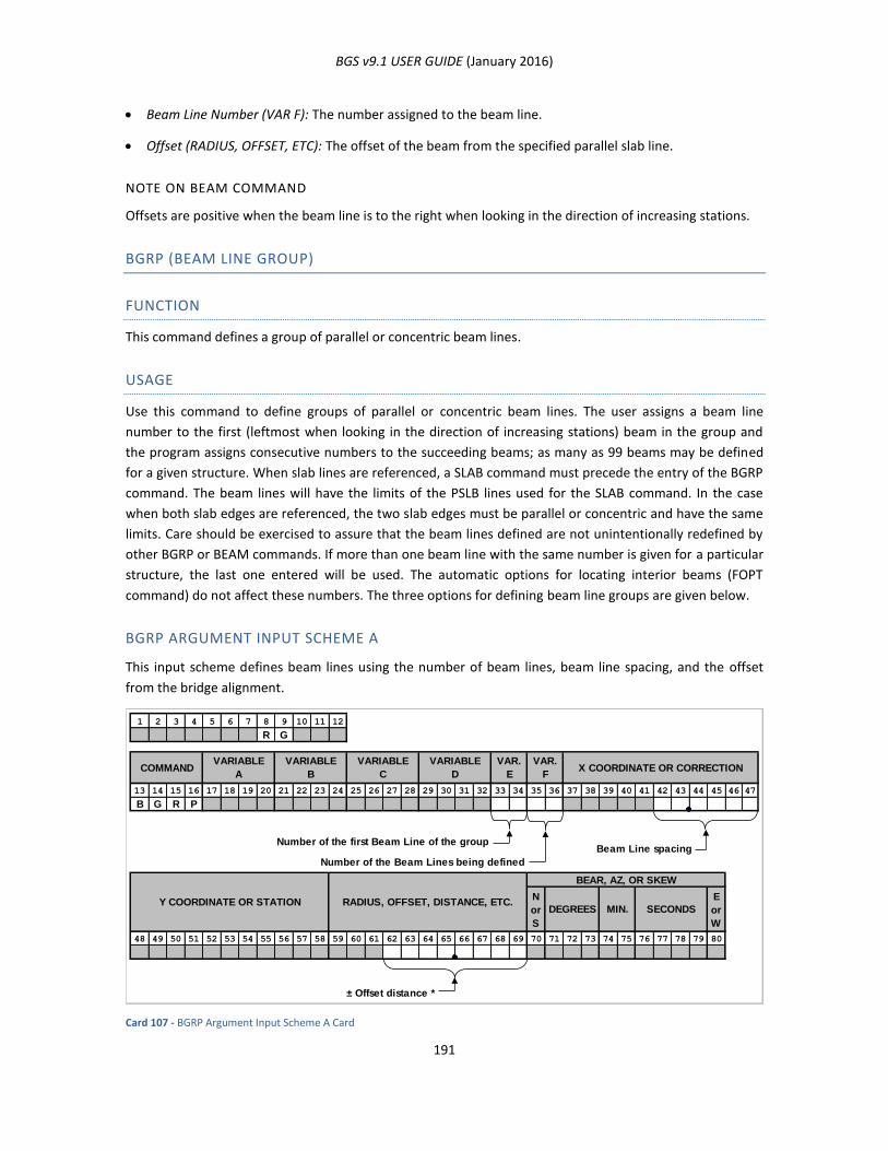
BGS v9.1 USER GUIDE (January 2016)
191
Beam Line Number (VAR F): The number assigned to the beam line.
Offset (RADIUS, OFFSET, ETC): The offset of the beam from the specified parallel slab line.
NOTE ON BEAM COMMAND
Offsets are positive when the beam line is to the right when looking in the direction of increasing stations.
BGRP (BEAM LINE GROUP)
FUNCTION
This command defines a group of parallel or concentric beam lines.
USAGE
Use this command to define groups of parallel or concentric beam lines. The user assigns a beam line
number to the first (leftmost when looking in the direction of increasing stations) beam in the group and
the program assigns consecutive numbers to the succeeding beams; as many as 99 beams may be defined
for a given structure. When slab lines are referenced, a SLAB command must precede the entry of the BGRP
command. The beam lines will have the limits of the PSLB lines used for the SLAB command. In the case
when both slab edges are referenced, the two slab edges must be parallel or concentric and have the same
limits. Care should be exercised to assure that the beam lines defined are not unintentionally redefined by
other BGRP or BEAM commands. If more than one beam line with the same number is given for a particular
structure, the last one entered will be used. The automatic options for locating interior beams (FOPT
command) do not affect these numbers. The three options for defining beam line groups are given below.
BGRP ARGUMENT INPUT SCHEME A
This input scheme defines beam lines using the number of beam lines, beam line spacing, and the offset
from the bridge alignment.
Card 107 - BGRP Argument Input Scheme A Card
1 2 3 4 5 6 7 8 9 10 11 12
R G
13 14 15 16 17 18 19 20 21 22 23 24 25 26 27 28 29 30 31 32 33 34 35 36 37 38 39 40 41 42 43 44 45 46 47
B G R P
Number of the first Beam Line of the groupBeam Line spacing
Number of the Beam Lines being defined
N
or
S
E
or
W
48 49 50 51 52 53 54 55 56 57 58 59 60 61 62 63 64 65 66 67 68 69 70 71 72 73 74 75 76 77 78 79 80
± Offset distance *
VARIABLE
D
VAR.
E
VAR.
FX COORDINATE OR CORRECTIONCOMMAND
VARIABLE
A
VARIABLE
B
VARIABLE
C
RADIUS, OFFSET, DISTANCE, ETC.Y COORDINATE OR STATIONSECONDSMIN.DEGREES
BEAR, AZ, OR SKEW
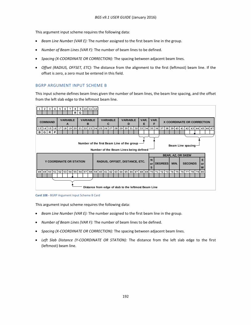
BGS v9.1 USER GUIDE (January 2016)
192
This argument input scheme requires the following data:
Beam Line Number (VAR E): The number assigned to the first beam line in the group.
Number of Beam Lines (VAR F): The number of beam lines to be defined.
Spacing (X-COORDINATE OR CORRECTION): The spacing between adjacent beam lines.
Offset (RADIUS, OFFSET, ETC): The distance from the alignment to the first (leftmost) beam line. If the
offset is zero, a zero must be entered in this field.
BGRP ARGUMENT INPUT SCHEME B
This input scheme defines beam lines given the number of beam lines, the beam line spacing, and the offset
from the left slab edge to the leftmost beam line.
Card 108 - BGRP Argument Input Scheme B Card
This argument input scheme requires the following data:
Beam Line Number (VAR E): The number assigned to the first beam line in the group.
Number of Beam Lines (VAR F): The number of beam lines to be defined.
Spacing (X-COORDINATE OR CORRECTION): The spacing between adjacent beam lines.
Left Slab Distance (Y-COORDINATE OR STATION): The distance from the left slab edge to the first
(leftmost) beam line.
1 2 3 4 5 6 7 8 9 10 11 12
R G
13 14 15 16 17 18 19 20 21 22 23 24 25 26 27 28 29 30 31 32 33 34 35 36 37 38 39 40 41 42 43 44 45 46 47
B G R P
Number of the first Beam Line of the groupBeam Line spacing
Number of the Beam Lines being defined
N
or
S
E
or
W
48 49 50 51 52 53 54 55 56 57 58 59 60 61 62 63 64 65 66 67 68 69 70 71 72 73 74 75 76 77 78 79 80
Distance from edge of slab to the leftmost Beam Line
VARIABLE
B
VARIABLE
ACOMMAND
VAR.
F
Y COORDINATE OR STATION
VAR.
EX COORDINATE OR CORRECTION
SECONDSMIN.DEGREES
BEAR, AZ, OR SKEW
RADIUS, OFFSET, DISTANCE, ETC.
VARIABLE
D
VARIABLE
C
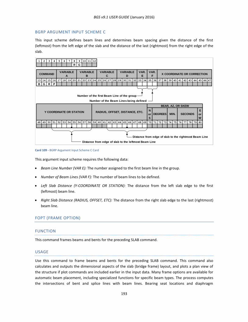
BGS v9.1 USER GUIDE (January 2016)
193
BGRP ARGUMENT INPUT SCHEME C
This input scheme defines beam lines and determines beam spacing given the distance of the first
(leftmost) from the left edge of the slab and the distance of the last (rightmost) from the right edge of the
slab.
Card 109 - BGRP Argument Input Scheme C Card
This argument input scheme requires the following data:
Beam Line Number (VAR E): The number assigned to the first beam line in the group.
Number of Beam Lines (VAR F): The number of beam lines to be defined.
Left Slab Distance (Y-COORDINATE OR STATION): The distance from the left slab edge to the first
(leftmost) beam line.
Right Slab Distance (RADIUS, OFFSET, ETC): The distance from the right slab edge to the last (rightmost)
beam line.
FOPT (FRAME OPTION)
FUNCTION
This command frames beams and bents for the preceding SLAB command.
USAGE
Use this command to frame beams and bents for the preceding SLAB command. This command also
calculates and outputs the dimensional aspects of the slab (bridge frame) layout, and plots a plan view of
the structure if plot commands are included earlier in the input data. Many frame options are available for
automatic beam placement, including specialized functions for specific beam types. The process computes
the intersections of bent and splice lines with beam lines. Bearing seat locations and diaphragm
1 2 3 4 5 6 7 8 9 10 11 12
R G
13 14 15 16 17 18 19 20 21 22 23 24 25 26 27 28 29 30 31 32 33 34 35 36 37 38 39 40 41 42 43 44 45 46 47
B G R P
Number of the first Beam Line of the group
Number of the Beam Lines being defined
N
or
S
E
or
W
48 49 50 51 52 53 54 55 56 57 58 59 60 61 62 63 64 65 66 67 68 69 70 71 72 73 74 75 76 77 78 79 80
Distance from edge of slab to the rightmost Beam Line
Distance from edge of slab to the leftmost Beam Line
Y COORDINATE OR STATION
VARIABLE
D
VARIABLE
C
VARIABLE
B
VARIABLE
ACOMMAND
VAR.
FX COORDINATE OR CORRECTION
VAR.
E
RADIUS, OFFSET, DISTANCE, ETC.SECONDSMIN.DEGREES
BEAR, AZ, OR SKEW
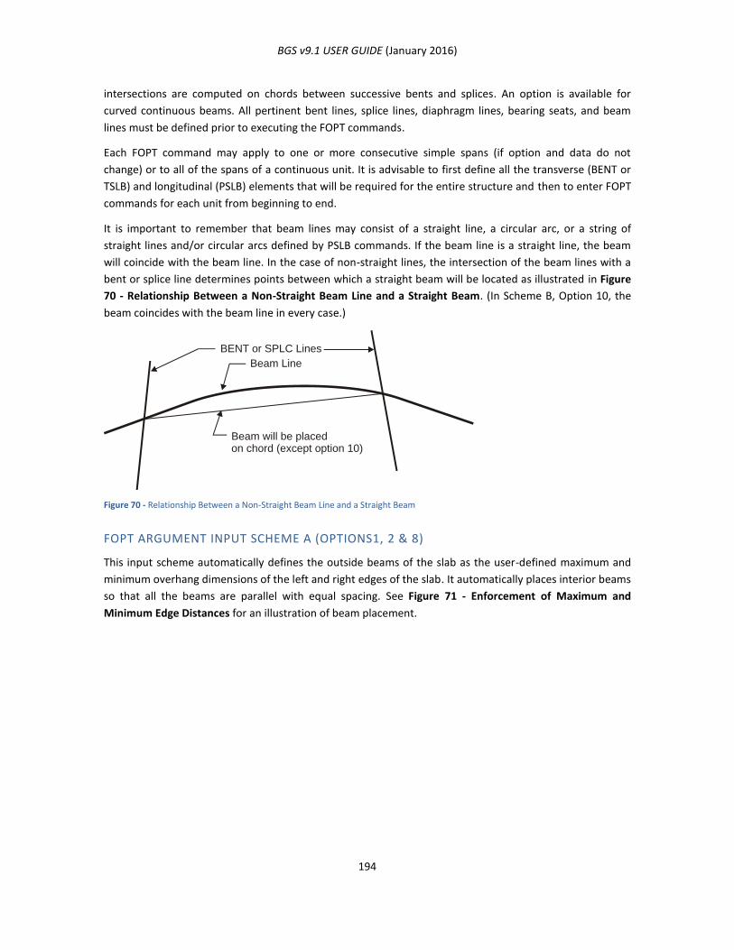
BGS v9.1 USER GUIDE (January 2016)
194
intersections are computed on chords between successive bents and splices. An option is available for
curved continuous beams. All pertinent bent lines, splice lines, diaphragm lines, bearing seats, and beam
lines must be defined prior to executing the FOPT commands.
Each FOPT command may apply to one or more consecutive simple spans (if option and data do not
change) or to all of the spans of a continuous unit. It is advisable to first define all the transverse (BENT or
TSLB) and longitudinal (PSLB) elements that will be required for the entire structure and then to enter FOPT
commands for each unit from beginning to end.
It is important to remember that beam lines may consist of a straight line, a circular arc, or a string of
straight lines and/or circular arcs defined by PSLB commands. If the beam line is a straight line, the beam
will coincide with the beam line. In the case of non-straight lines, the intersection of the beam lines with a
bent or splice line determines points between which a straight beam will be located as illustrated in Figure
70 - Relationship Between a Non-Straight Beam Line and a Straight Beam. (In Scheme B, Option 10, the
beam coincides with the beam line in every case.)
Figure 70 - Relationship Between a Non-Straight Beam Line and a Straight Beam
FOPT ARGUMENT INPUT SCHEME A (OPTIONS1, 2 & 8)
This input scheme automatically defines the outside beams of the slab as the user-defined maximum and
minimum overhang dimensions of the left and right edges of the slab. It automatically places interior beams
so that all the beams are parallel with equal spacing. See Figure 71 - Enforcement of Maximum and
Minimum Edge Distances for an illustration of beam placement.
BENT or SPLC Lines
Beam will be placedon chord (except option 10)
Beam Line
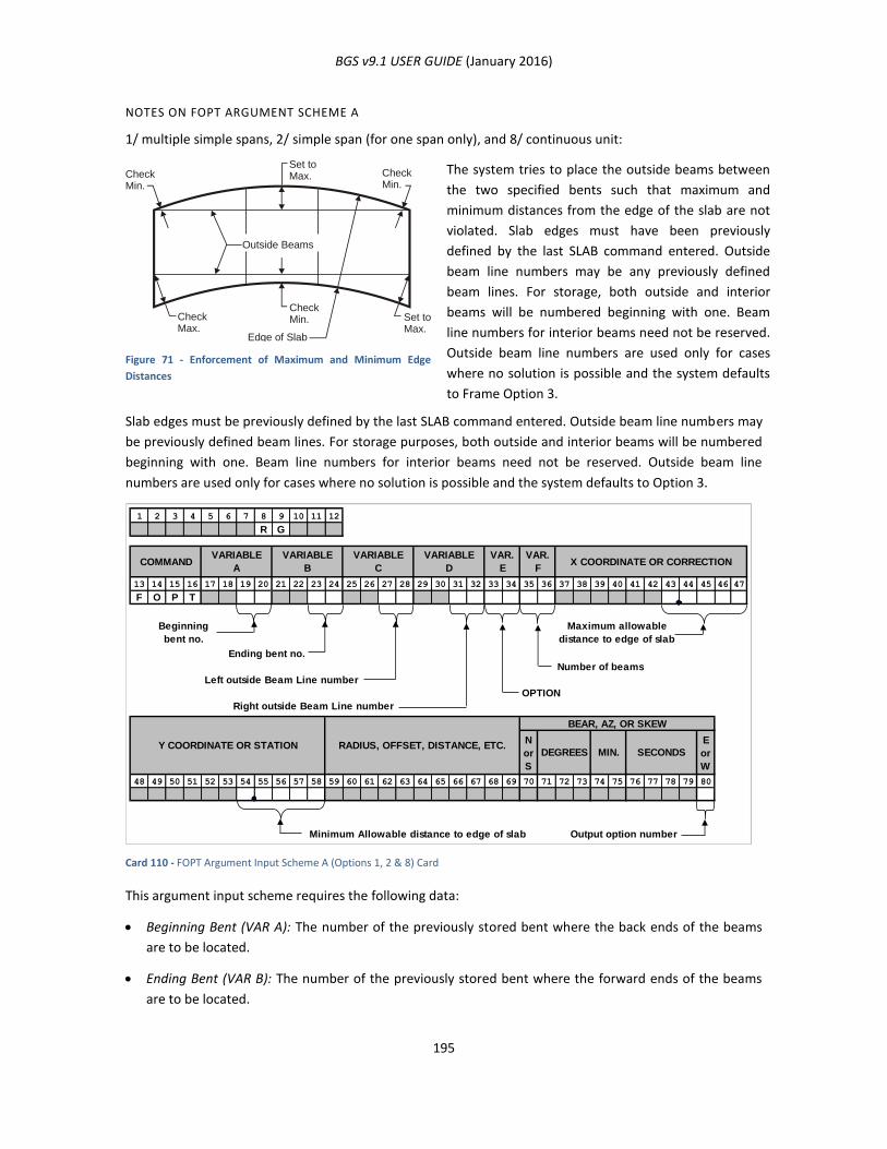
BGS v9.1 USER GUIDE (January 2016)
195
NOTES ON FOPT ARGUMENT SCHEME A
1/ multiple simple spans, 2/ simple span (for one span only), and 8/ continuous unit:
Figure 71 - Enforcement of Maximum and Minimum Edge
Distances
The system tries to place the outside beams between
the two specified bents such that maximum and
minimum distances from the edge of the slab are not
violated. Slab edges must have been previously
defined by the last SLAB command entered. Outside
beam line numbers may be any previously defined
beam lines. For storage, both outside and interior
beams will be numbered beginning with one. Beam
line numbers for interior beams need not be reserved.
Outside beam line numbers are used only for cases
where no solution is possible and the system defaults
to Frame Option 3.
Slab edges must be previously defined by the last SLAB command entered. Outside beam line numbers may
be previously defined beam lines. For storage purposes, both outside and interior beams will be numbered
beginning with one. Beam line numbers for interior beams need not be reserved. Outside beam line
numbers are used only for cases where no solution is possible and the system defaults to Option 3.
Card 110 - FOPT Argument Input Scheme A (Options 1, 2 & 8) Card
This argument input scheme requires the following data:
Beginning Bent (VAR A): The number of the previously stored bent where the back ends of the beams
are to be located.
Ending Bent (VAR B): The number of the previously stored bent where the forward ends of the beams
are to be located.
CheckMin.
CheckMax.
Set toMax.
Set toMax. Check
Min.
CheckMin.
Outside Beams
Edge of Slab
1 2 3 4 5 6 7 8 9 10 11 12
R G
13 14 15 16 17 18 19 20 21 22 23 24 25 26 27 28 29 30 31 32 33 34 35 36 37 38 39 40 41 42 43 44 45 46 47
F O P T
Beginning
bent no.
Maximum allowable
distance to edge of slab
Ending bent no.
Number of beams
Left outside Beam Line number
OPTION
Right outside Beam Line number
N
or
S
E
or
W
48 49 50 51 52 53 54 55 56 57 58 59 60 61 62 63 64 65 66 67 68 69 70 71 72 73 74 75 76 77 78 79 80
Minimum Allowable distance to edge of slab Output option number
VARIABLE
B
VARIABLE
A
RADIUS, OFFSET, DISTANCE, ETC.Y COORDINATE OR STATION
COMMANDVARIABLE
C
VARIABLE
D
VAR.
E
SECONDSMIN.DEGREES
BEAR, AZ, OR SKEW
VAR.
FX COORDINATE OR CORRECTION

BGS v9.1 USER GUIDE (January 2016)
196
Left Outside Beam Line (VAR C): The number of the previously stored beam line to be the default left
outside beam line. This is for the case where no outside beams can be constructed for the slab with the
given maximum and minimum overhang dimensions and the program defaults from Frame Option 1 to
Frame Option 3.
Right Outside Beam Line (VAR D): The number of the previously stored beam line to be the default right
outside beam line. This is for the case where no outside beams can be constructed for the slab with the
given maximum and minimum overhang dimensions and the program defaults from Frame Option 1 to
Frame Option 3.
Frame Option (VAR E): The option number defining the layout of the beams. Use 1 for a multiple span
layout, 2 for a simple span layout, or 8 for a continuous unit layout. See the illustration above.
Number of Beams (VAR F): The number of beams to be placed in each span.
Maximum Edge of Slab Distance (X-COORDINATE OR CORRECTION): The maximum distance the outside
beams may be placed from the edge of the slab; that is, the maximum overhang permitted for the left
and right edges of the slab.
Minimum Edge of Slab Distance (Y-COORDINATE OR STATION): The minimum distance the outside
beams may be placed from the edge of the slab; that is, the minimum overhang permitted for the left
and right edges of the slab.
Output Option (BEAR, AZ, OR SKEW): No entry or an entry of zero omits the beam coordinate report and
produces the frame plot if the appropriate plot command is specified. An entry of one produces the
beam coordinate report and the frame plot. An entry of two produces the beam coordinate report and
omits the frame plot. An entry of three omits both the beam coordinate report and the frame plot.
FOPT ARGUMENT INPUT SCHEME B (OPTIONS 4, 9 &10)
Frames the slab using a series of previously defined beam lines numbered consecutively from the left
outside beam to the right outside beam. The beam placement is dependent upon the intersection of the
beam lines with bent or splice intersections in accordance with the options illustrated below.
Figure 72 - Frame Option 4/ simple span (Command may refer to
more than 1 span)
All beam and bent lines and the bearing
scheme(s) and distances for the structure must
be previously defined by one of the available
methods and must be numbered consecutively
from the left outside beam to the right outside
beam. The beam placement depends on the
intersection of the beam lines with bent or
bearing lines.
Beam Chords
Bent Lines
Beam Lines
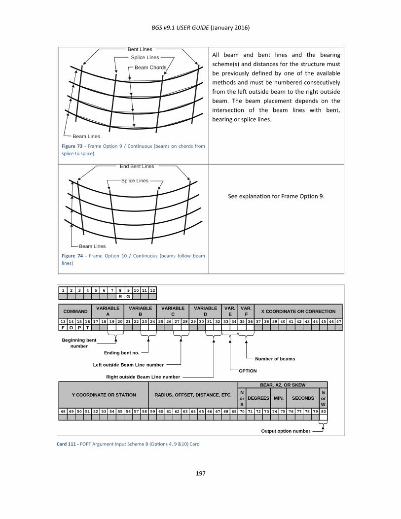
BGS v9.1 USER GUIDE (January 2016)
197
Figure 73 - Frame Option 9 / Continuous (beams on chords from
splice to splice)
All beam and bent lines and the bearing
scheme(s) and distances for the structure must
be previously defined by one of the available
methods and must be numbered consecutively
from the left outside beam to the right outside
beam. The beam placement depends on the
intersection of the beam lines with bent,
bearing or splice lines.
Figure 74 - Frame Option 10 / Continuous (beams follow beam
lines)
See explanation for Frame Option 9.
Card 111 - FOPT Argument Input Scheme B (Options 4, 9 &10) Card
Beam Chords
Bent Lines
Splice Lines
Beam Lines
End Bent Lines
Splice Lines
Beam Lines
1 2 3 4 5 6 7 8 9 10 11 12
R G
13 14 15 16 17 18 19 20 21 22 23 24 25 26 27 28 29 30 31 32 33 34 35 36 37 38 39 40 41 42 43 44 45 46 47
F O P T
Ending bent no.
Number of beams
Left outside Beam Line number
OPTION
Right outside Beam Line number
N
or
S
E
or
W
48 49 50 51 52 53 54 55 56 57 58 59 60 61 62 63 64 65 66 67 68 69 70 71 72 73 74 75 76 77 78 79 80
Output option number
RADIUS, OFFSET, DISTANCE, ETC.Y COORDINATE OR STATION
COMMANDVARIABLE
A
VARIABLE
B
VARIABLE
C
VARIABLE
D
VAR.
E
Beginning bent
number
SECONDSMIN.DEGREES
BEAR, AZ, OR SKEW
VAR.
FX COORDINATE OR CORRECTION
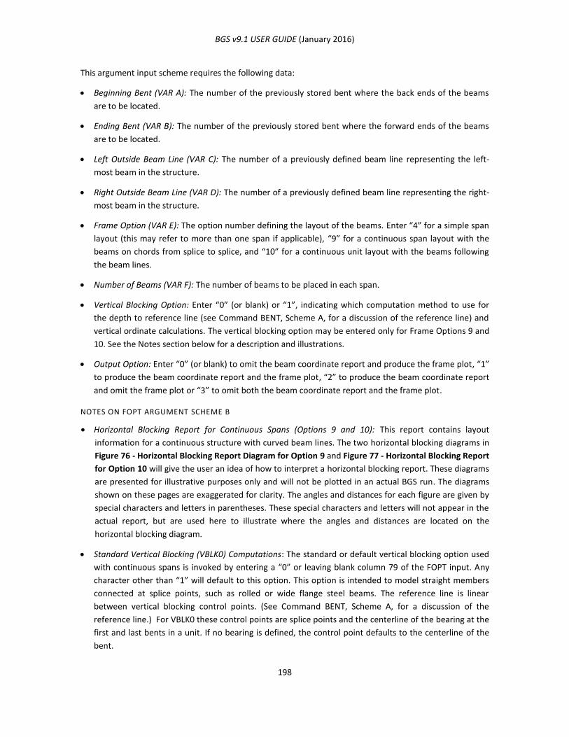
BGS v9.1 USER GUIDE (January 2016)
198
This argument input scheme requires the following data:
Beginning Bent (VAR A): The number of the previously stored bent where the back ends of the beams
are to be located.
Ending Bent (VAR B): The number of the previously stored bent where the forward ends of the beams
are to be located.
Left Outside Beam Line (VAR C): The number of a previously defined beam line representing the left-
most beam in the structure.
Right Outside Beam Line (VAR D): The number of a previously defined beam line representing the right-
most beam in the structure.
Frame Option (VAR E): The option number defining the layout of the beams. Enter “4” for a simple span
layout (this may refer to more than one span if applicable), “9” for a continuous span layout with the
beams on chords from splice to splice, and “10” for a continuous unit layout with the beams following
the beam lines.
Number of Beams (VAR F): The number of beams to be placed in each span.
Vertical Blocking Option: Enter “0” (or blank) or “1”, indicating which computation method to use for
the depth to reference line (see Command BENT, Scheme A, for a discussion of the reference line) and
vertical ordinate calculations. The vertical blocking option may be entered only for Frame Options 9 and
10. See the Notes section below for a description and illustrations.
Output Option: Enter “0” (or blank) to omit the beam coordinate report and produce the frame plot, “1”
to produce the beam coordinate report and the frame plot, “2” to produce the beam coordinate report
and omit the frame plot or “3” to omit both the beam coordinate report and the frame plot.
NOTES ON FOPT ARGUMENT SCHEME B
Horizontal Blocking Report for Continuous Spans (Options 9 and 10): This report contains layout
information for a continuous structure with curved beam lines. The two horizontal blocking diagrams in
Figure 76 - Horizontal Blocking Report Diagram for Option 9 and Figure 77 - Horizontal Blocking Report
for Option 10 will give the user an idea of how to interpret a horizontal blocking report. These diagrams
are presented for illustrative purposes only and will not be plotted in an actual BGS run. The diagrams
shown on these pages are exaggerated for clarity. The angles and distances for each figure are given by
special characters and letters in parentheses. These special characters and letters will not appear in the
actual report, but are used here to illustrate where the angles and distances are located on the
horizontal blocking diagram.
Standard Vertical Blocking (VBLK0) Computations: The standard or default vertical blocking option used
with continuous spans is invoked by entering a “0” or leaving blank column 79 of the FOPT input. Any
character other than “1” will default to this option. This option is intended to model straight members
connected at splice points, such as rolled or wide flange steel beams. The reference line is linear
between vertical blocking control points. (See Command BENT, Scheme A, for a discussion of the
reference line.) For VBLK0 these control points are splice points and the centerline of the bearing at the
first and last bents in a unit. If no bearing is defined, the control point defaults to the centerline of the
bent.

BGS v9.1 USER GUIDE (January 2016)
199
The depth to the reference line specified at an end bent is applied at the centerline of the bearing seat if
one exists. At splice points, the reference line elevation is obtained by subtracting the depth to the
reference line specified on the splice command from the surface elevation at the splice.
At intermediate bent locations, any depth value input on the command will be ignored. A reference line
depth will be calculated by subtracting from the surface elevation a reference line elevation
interpolated between the nearest control points on either side of the intermediate bent. Reference line
elevations and depths at diaphragm locations are calculated in the same manner. The vertical ordinate
is the elevation difference between the reference line at a given point and the lower of the two end
bearings. See Figure 79 - Standard Vertical Blocking Command for an illustration of the standard
vertical blocking command.
Alternate Vertical Blocking (VBLK1) Computations: This option may be used only for Frame Options 9
and 10 and is invoked by placing a “1” in column 79. This option is intended to model a plate girder
whose web has been cut to follow at a fixed or linearly varying depth below the roadway surface.
The reference line follows the roadway surface at a depth that varies linearly between control points.
For VBLK1 these are the same as the control points defined for the standard option, VBLK0.
A calculated reference line depth at a diaphragm or an intermediate bent will be linearly interpolated
between the reference line depths input for the control point on either side of the point in question. As
with the standard option, a reference line depth input at an intermediate bent will be replaced by a
calculated depth.
Reference line elevations at all points are found by subtracting the reference line depths from the
corresponding surface elevations. Vertical ordinates at all points are found by subtracting the reference
line elevation of the lower of the two end bearing seats from the reference line elevation of the point in
question. See Figure 80 - Alternate Vertical Blocking Command for an illustration of the alternate
vertical blocking command.
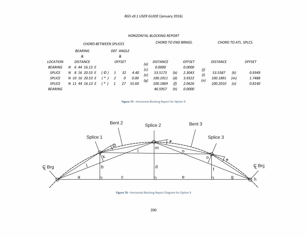
BGS v9.1 USER GUIDE (January 2016)
200
HORIZONTAL BLOCKING REPORT
LOCATION
CHORD BETWEEN SPLICES
(a)
(c)
(e)
(g)
CHORD TO END BRNGS.
(j)
(l)
(n)
CHORD TO ATL. SPLCS.
BEARING
&
DISTANCE
DEF ANGLE
&
OFFSET DISTANCE OFFSET DISTANCE OFFSET
BEARING
SPLICE
SPLICE
SPLICE
BEARING
N 6 44 16.13 E
N 8 16 20.53 E
N 10 16 20.53 E
N 11 44 16.13 E
( © ) 1 32 4.40
( * ) 2 0 0.00
( * ) 1 27 55.60
0.0000
53.5173
100.1911
100.1869
46.5957
(b)
(d)
(f)
(h)
0.0000
2.3043
3.9322
2.0626
0.0000
53.5587
100.1891
100.2010
(k)
(m)
(o)
0.9349
1.7488
0.8140
Figure 75 - Horizontal Blocking Report for Option 9
Figure 76 - Horizontal Blocking Report Diagram for Option 9
C Brg C Brg
Splice 1
Bent 2 Bent 3Splice 2
Splice 3
L
a
j
k
lm
n
o
fdb
c
*
*
e gh
L
c
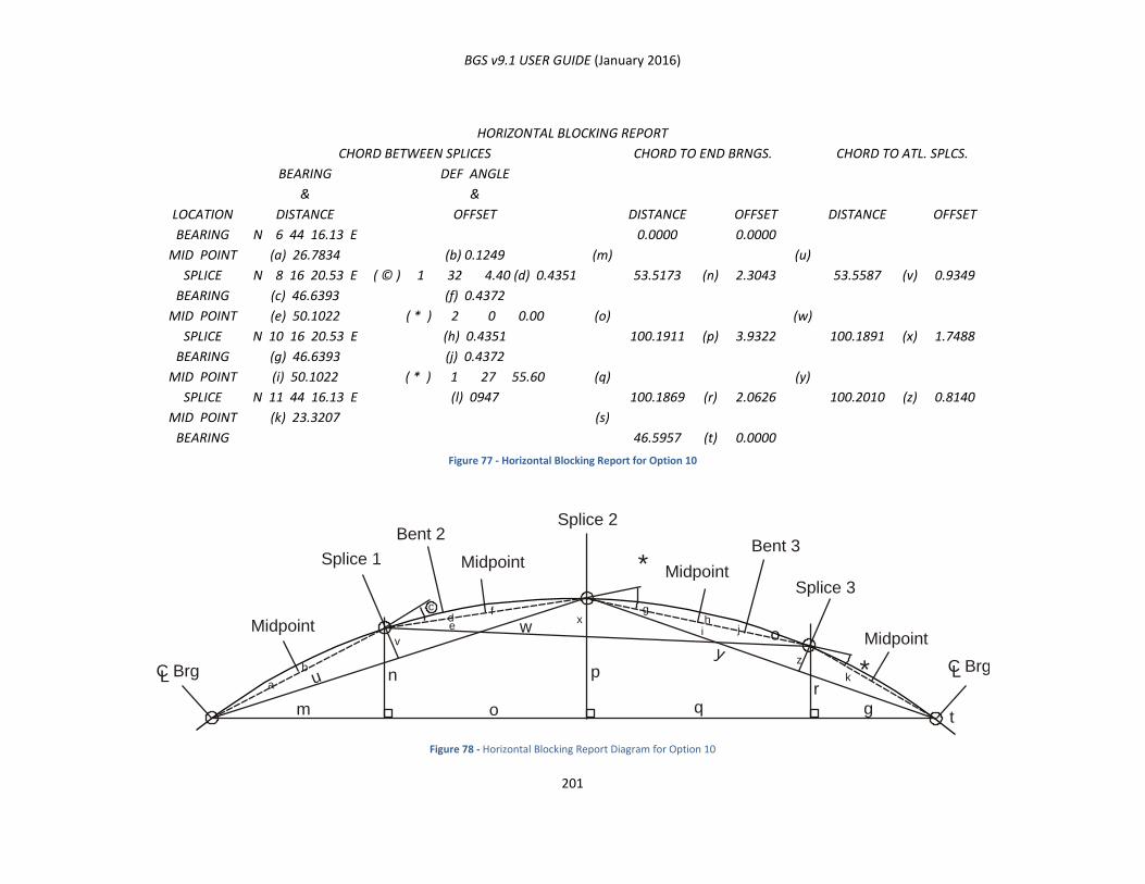
BGS v9.1 USER GUIDE (January 2016)
201
HORIZONTAL BLOCKING REPORT
LOCATION
CHORD BETWEEN SPLICES
(m)
(o)
(q)
(s)
CHORD TO END BRNGS.
(u)
(w)
(y)
CHORD TO ATL. SPLCS.
BEARING
&
DISTANCE
DEF ANGLE
&
OFFSET DISTANCE OFFSET DISTANCE OFFSET
BEARING
MID POINT
SPLICE
BEARING
MID POINT
SPLICE
BEARING
MID POINT
SPLICE
MID POINT
BEARING
N 6 44 16.13 E
(a) 26.7834
N 8 16 20.53 E
(c) 46.6393
(e) 50.1022
N 10 16 20.53 E
(g) 46.6393
(i) 50.1022
N 11 44 16.13 E
(k) 23.3207
(b) 0.1249
( © ) 1 32 4.40 (d) 0.4351
(f) 0.4372
( * ) 2 0 0.00
(h) 0.4351
(j) 0.4372
( * ) 1 27 55.60
(l) 0947
0.0000
53.5173
100.1911
100.1869
46.5957
(n)
(p)
(r)
(t)
0.0000
2.3043
3.9322
2.0626
0.0000
53.5587
100.1891
100.2010
(v)
(x)
(z)
0.9349
1.7488
0.8140
Figure 77 - Horizontal Blocking Report for Option 10
Figure 78 - Horizontal Blocking Report Diagram for Option 10
Midpoint
Midpoint
Midpoint
Midpoint
C Brg C Brg
Splice 1
Bent 2Bent 3
Splice 2
Splice 3
L
m
u
w
p
hg
j
f
ex
b
a
vi
z
k
yo
rn
o q gt
L
*
*
c
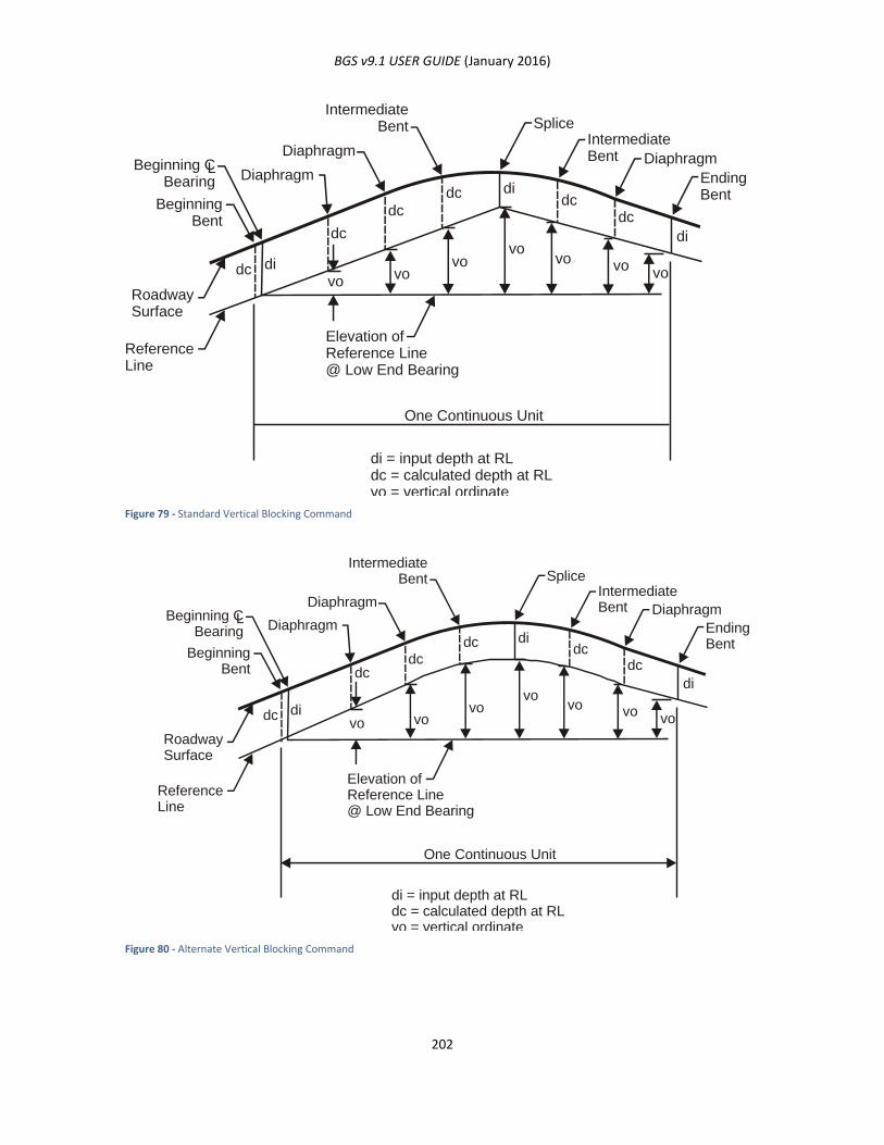
BGS v9.1 USER GUIDE (January 2016)
202
Figure 79 - Standard Vertical Blocking Command
Figure 80 - Alternate Vertical Blocking Command
Splice
L
BeginningBent
Beginning CBearing Diaphragm
Diaphragm
IntermediateBent
IntermediateBent
EndingBent
RoadwaySurface
ReferenceLine
Elevation ofReference Line@ Low End Bearing
One Continuous Unit
di = input depth at RLdc = calculated depth at RLvo = vertical ordinate
dcvo
vovo
vovo vo
vodi
di
didc
dc
dcdc
dc
Diaphragm
Splice
L
BeginningBent
Beginning CBearing Diaphragm
Diaphragm
IntermediateBent
IntermediateBent
EndingBent
RoadwaySurface
ReferenceLine
Elevation ofReference Line@ Low End Bearing
One Continuous Unit
di = input depth at RLdc = calculated depth at RLvo = vertical ordinate
dcvo vo
vovo
vo vovo
di
di
didc
dc
dcdc
dc
Diaphragm

BGS v9.1 USER GUIDE (January 2016)
203
FOPT ARGUMENT INPUT SCHEME C (OPTIONS 6 &7)
For this input scheme interior beams are automatically spaced based on specified maximum and minimum
spacing within the given outside beam lines. Beam spacing at bents and beam flares are determined
according to the following options, as illustrated in Error! Reference source not found. and Figure 82 - 7/
simple span (command may refer to more than 1 span).
Figure 81 - 6/ simple span (command may refer to more than 1
span)
The number of beams is based on maximum
(NORMAL) beam spacing on the longest bent. As
many beams as possible are placed parallel to the
first outside beam without violating minimum
beam spacing. Remaining beams are flared.
Outside beam numbers may be any previously
defined beam lines. Both outside and interior
beams will be numbered beginning with one for
storage. Beam line numbers for interior beams
need not be reserved.
Figure 82 - 7/ simple span (command may refer to more than 1
span)
The number of beams is based on maximum
(NORMAL) beam spacing on the longest bent. As
many beams as possible are placed parallel to
both outside beams without violating minimum
beam spacing. Remaining beams are flared.
Outside beam numbers may be any previously
defined beam lines. Both outside and interior
beams will be numbered beginning with one for
storage. Beam line numbers for interior beams
need not be reserved.
First outsideBeam Line
Second outsideBeam Line
Parallel
EqualSpaces
Min.>
EqualSpaces
Max.<
OutsideBeam Line
OutsideBeam Line
Parallel
Parallel
EqualSpaces
Min.>EqualSpaces
Max.<
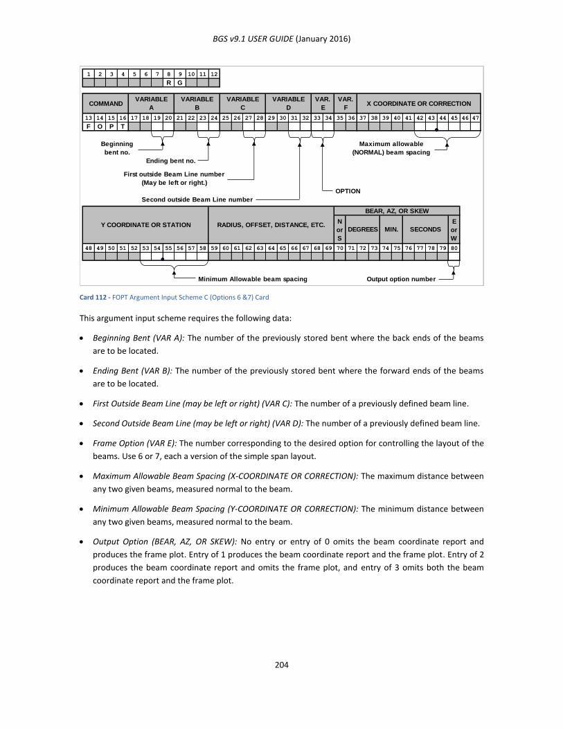
BGS v9.1 USER GUIDE (January 2016)
204
Card 112 - FOPT Argument Input Scheme C (Options 6 &7) Card
This argument input scheme requires the following data:
Beginning Bent (VAR A): The number of the previously stored bent where the back ends of the beams
are to be located.
Ending Bent (VAR B): The number of the previously stored bent where the forward ends of the beams
are to be located.
First Outside Beam Line (may be left or right) (VAR C): The number of a previously defined beam line.
Second Outside Beam Line (may be left or right) (VAR D): The number of a previously defined beam line.
Frame Option (VAR E): The number corresponding to the desired option for controlling the layout of the
beams. Use 6 or 7, each a version of the simple span layout.
Maximum Allowable Beam Spacing (X-COORDINATE OR CORRECTION): The maximum distance between
any two given beams, measured normal to the beam.
Minimum Allowable Beam Spacing (Y-COORDINATE OR CORRECTION): The minimum distance between
any two given beams, measured normal to the beam.
Output Option (BEAR, AZ, OR SKEW): No entry or entry of 0 omits the beam coordinate report and
produces the frame plot. Entry of 1 produces the beam coordinate report and the frame plot. Entry of 2
produces the beam coordinate report and omits the frame plot, and entry of 3 omits both the beam
coordinate report and the frame plot.
1 2 3 4 5 6 7 8 9 10 11 12
R G
COMMAND
13 14 15 16 17 18 19 20 21 22 23 24 25 26 27 28 29 30 31 32 33 34 35 36 37 38 39 40 41 42 43 44 45 46 47
F O P T
Beginning
bent no.
Ending bent no.
First outside Beam Line number
(May be left or right.)
OPTION
Second outside Beam Line number
N
or
S
E
or
W
48 49 50 51 52 53 54 55 56 57 58 59 60 61 62 63 64 65 66 67 68 69 70 71 72 73 74 75 76 77 78 79 80
Minimum Allowable beam spacing Output option number
RADIUS, OFFSET, DISTANCE, ETC.Y COORDINATE OR STATION
VARIABLE
A
VARIABLE
B
VARIABLE
C
VARIABLE
D
VAR.
E
MIN.DEGREES
BEAR, AZ, OR SKEW
VAR.
FX COORDINATE OR CORRECTION
SECONDS
Maximum allowable
(NORMAL) beam spacing
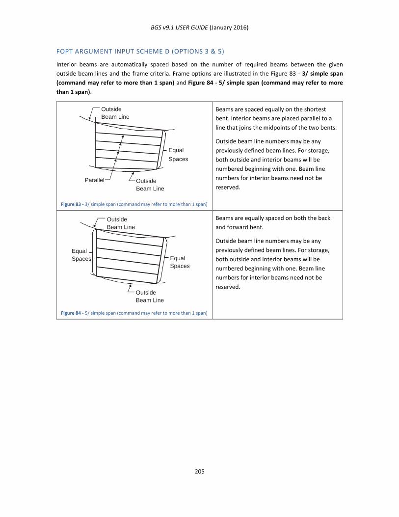
BGS v9.1 USER GUIDE (January 2016)
205
FOPT ARGUMENT INPUT SCHEME D (OPTIONS 3 & 5)
Interior beams are automatically spaced based on the number of required beams between the given
outside beam lines and the frame criteria. Frame options are illustrated in the Figure 83 - 3/ simple span
(command may refer to more than 1 span) and Figure 84 - 5/ simple span (command may refer to more
than 1 span).
Figure 83 - 3/ simple span (command may refer to more than 1 span)
Beams are spaced equally on the shortest
bent. Interior beams are placed parallel to a
line that joins the midpoints of the two bents.
Outside beam line numbers may be any
previously defined beam lines. For storage,
both outside and interior beams will be
numbered beginning with one. Beam line
numbers for interior beams need not be
reserved.
Figure 84 - 5/ simple span (command may refer to more than 1 span)
Beams are equally spaced on both the back
and forward bent.
Outside beam line numbers may be any
previously defined beam lines. For storage,
both outside and interior beams will be
numbered beginning with one. Beam line
numbers for interior beams need not be
reserved.
Outside Beam Line
Parallel
Equal
Spaces
Outside Beam Line
Outside Beam Line
Equal Spaces
Equal Spaces
Outside Beam Line

BGS v9.1 USER GUIDE (January 2016)
206
Card 113 - FOPT Argument Input Scheme D (Options 3 & 5) Card
This argument input scheme requires the following data:
Beginning Bent (VAR A): The number of the previously stored bent where the back ends of the beams
are to be located.
Ending Bent (VAR B): The number of the previously stored bent where the forward ends of the beams
are to be located.
Left Outside Beam Line (VAR C): The number of a previously defined beam line referring to the leftmost
beam in the structure.
Right Outside Beam Line (VAR D): The number of a previously defined beam line referring to the
rightmost beam in the structure.
Frame Option (VAR E): The option number defining the layout of the beams. Use 3 or 5, each a version
of the simple span layout.
Number of Beams (VAR F): The number of beams to be placed in each span.
Output Option (BEAR, AZ, OR SKEW): Entering blank or “0” omits the beam coordinate report and
produces the frame plot. Entering “1” produces the beam coordinate report and the frame plot.
Entering “2” produces the beam coordinate report and omits the frame plot. Entering “3” omits both
the beam coordinate report and the frame plot.
1 2 3 4 5 6 7 8 9 10 11 12
R G
13 14 15 16 17 18 19 20 21 22 23 24 25 26 27 28 29 30 31 32 33 34 35 36 37 38 39 40 41 42 43 44 45 46 47
F O P T
Beginning
bent no.
Ending bent no.
Number of beams
Left outside Beam Line number
OPTION
Right outside Beam Line number
N
or
S
E
or
W
48 49 50 51 52 53 54 55 56 57 58 59 60 61 62 63 64 65 66 67 68 69 70 71 72 73 74 75 76 77 78 79 80
Output option number
RADIUS, OFFSET, DISTANCE, ETC.Y COORDINATE OR STATION
COMMANDVARIABLE
A
VARIABLE
B
VARIABLE
C
VARIABLE
D
VAR.
E
SECONDSMIN.DEGREES
BEAR, AZ, OR SKEW
VAR.
FX COORDINATE OR CORRECTION
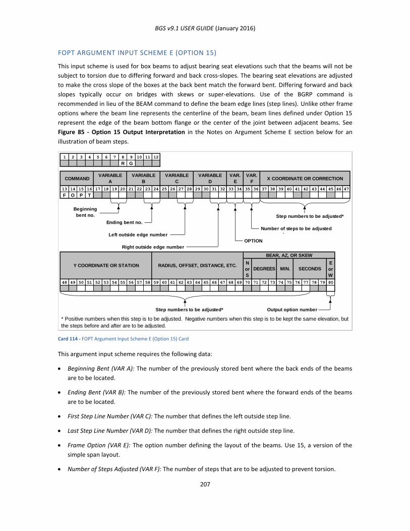
BGS v9.1 USER GUIDE (January 2016)
207
FOPT ARGUMENT INPUT SCHEME E (OPTION 15)
This input scheme is used for box beams to adjust bearing seat elevations such that the beams will not be
subject to torsion due to differing forward and back cross-slopes. The bearing seat elevations are adjusted
to make the cross slope of the boxes at the back bent match the forward bent. Differing forward and back
slopes typically occur on bridges with skews or super-elevations. Use of the BGRP command is
recommended in lieu of the BEAM command to define the beam edge lines (step lines). Unlike other frame
options where the beam line represents the centerline of the beam, beam lines defined under Option 15
represent the edge of the beam bottom flange or the center of the joint between adjacent beams. See
Figure 85 - Option 15 Output Interpretation in the Notes on Argument Scheme E section below for an
illustration of beam steps.
Card 114 - FOPT Argument Input Scheme E (Option 15) Card
This argument input scheme requires the following data:
Beginning Bent (VAR A): The number of the previously stored bent where the back ends of the beams
are to be located.
Ending Bent (VAR B): The number of the previously stored bent where the forward ends of the beams
are to be located.
First Step Line Number (VAR C): The number that defines the left outside step line.
Last Step Line Number (VAR D): The number that defines the right outside step line.
Frame Option (VAR E): The option number defining the layout of the beams. Use 15, a version of the
simple span layout.
Number of Steps Adjusted (VAR F): The number of steps that are to be adjusted to prevent torsion.
1 2 3 4 5 6 7 8 9 10 11 12
R G
13 14 15 16 17 18 19 20 21 22 23 24 25 26 27 28 29 30 31 32 33 34 35 36 37 38 39 40 41 42 43 44 45 46 47
F O P T
Beginning
bent no. Step numbers to be adjusted*
Ending bent no.
Number of steps to be adjusted
Left outside edge number `
OPTION
Right outside edge number
N
or
S
E
or
W
48 49 50 51 52 53 54 55 56 57 58 59 60 61 62 63 64 65 66 67 68 69 70 71 72 73 74 75 76 77 78 79 80
Step numbers to be adjusted* Output option number
VARIABLE
A
VARIABLE
B
VARIABLE
C
VARIABLE
D
VAR.
F
* Positive numbers when this step is to be adjusted. Negative numbers when this step is to be kept the same elevation, but
the steps before and after are to be adjusted.
DEGREES MIN. SECONDS
X COORDINATE OR CORRECTION
BEAR, AZ, OR SKEW
RADIUS, OFFSET, DISTANCE, ETC.Y COORDINATE OR STATION
COMMANDVAR.
E
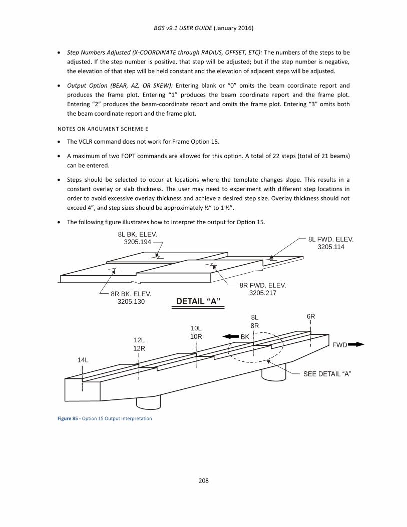
BGS v9.1 USER GUIDE (January 2016)
208
Step Numbers Adjusted (X-COORDINATE through RADIUS, OFFSET, ETC): The numbers of the steps to be
adjusted. If the step number is positive, that step will be adjusted; but if the step number is negative,
the elevation of that step will be held constant and the elevation of adjacent steps will be adjusted.
Output Option (BEAR, AZ, OR SKEW): Entering blank or “0” omits the beam coordinate report and
produces the frame plot. Entering “1” produces the beam coordinate report and the frame plot.
Entering “2” produces the beam-coordinate report and omits the frame plot. Entering “3” omits both
the beam coordinate report and the frame plot.
NOTES ON ARGUMENT SCHEME E
The VCLR command does not work for Frame Option 15.
A maximum of two FOPT commands are allowed for this option. A total of 22 steps (total of 21 beams)
can be entered.
Steps should be selected to occur at locations where the template changes slope. This results in a
constant overlay or slab thickness. The user may need to experiment with different step locations in
order to avoid excessive overlay thickness and achieve a desired step size. Overlay thickness should not
exceed 4”, and step sizes should be approximately ½” to 1 ½”.
The following figure illustrates how to interpret the output for Option 15.
Figure 85 - Option 15 Output Interpretation
8L BK. ELEV.3205.194
8R FWD. ELEV.3205.217
SEE DETAIL “A”
14L
12L
10L
8L
12R
10R
8R
6R
FWD
BK
8R BK. ELEV.3205.130
8L FWD. ELEV.3205.114
DETAIL “A”
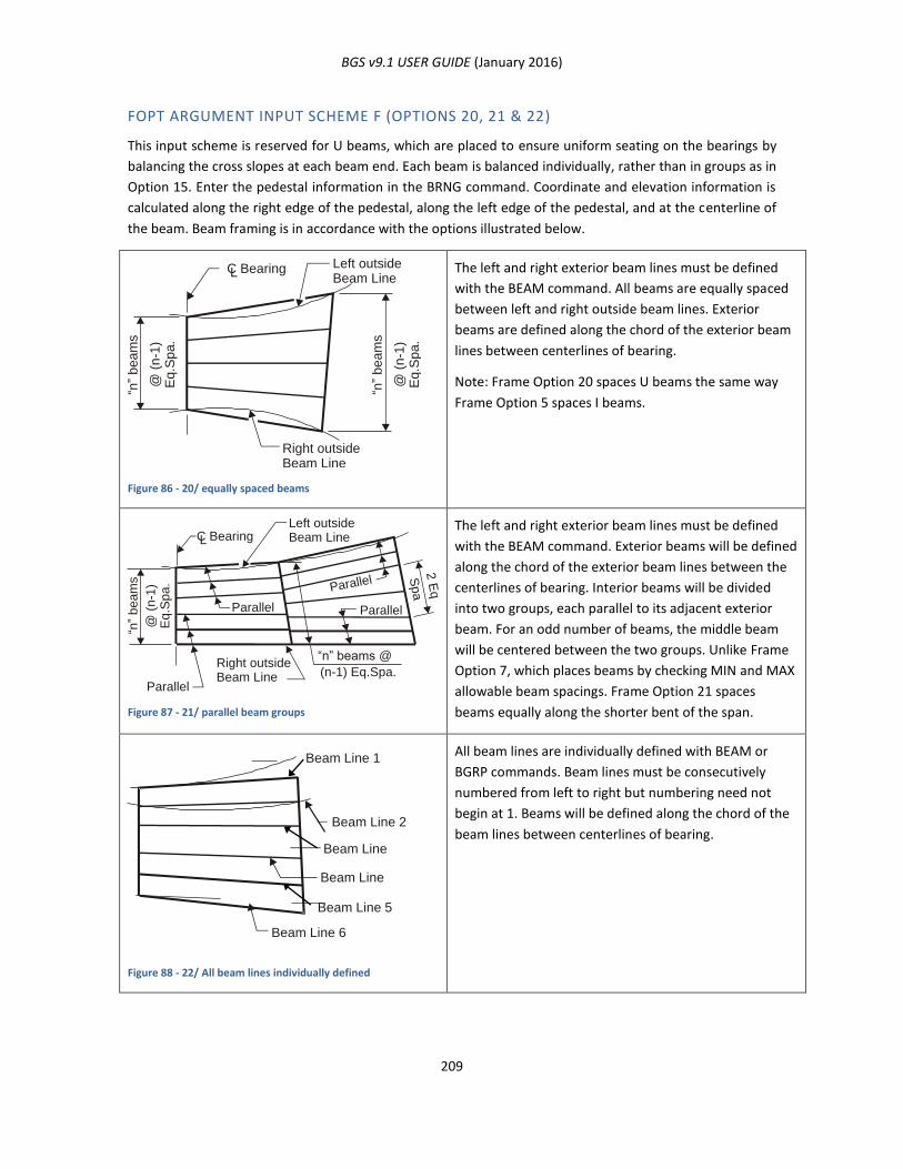
BGS v9.1 USER GUIDE (January 2016)
209
FOPT ARGUMENT INPUT SCHEME F (OPTIONS 20, 21 & 22)
This input scheme is reserved for U beams, which are placed to ensure uniform seating on the bearings by
balancing the cross slopes at each beam end. Each beam is balanced individually, rather than in groups as in
Option 15. Enter the pedestal information in the BRNG command. Coordinate and elevation information is
calculated along the right edge of the pedestal, along the left edge of the pedestal, and at the centerline of
the beam. Beam framing is in accordance with the options illustrated below.
Figure 86 - 20/ equally spaced beams
The left and right exterior beam lines must be defined
with the BEAM command. All beams are equally spaced
between left and right outside beam lines. Exterior
beams are defined along the chord of the exterior beam
lines between centerlines of bearing.
Note: Frame Option 20 spaces U beams the same way
Frame Option 5 spaces I beams.
Figure 87 - 21/ parallel beam groups
The left and right exterior beam lines must be defined
with the BEAM command. Exterior beams will be defined
along the chord of the exterior beam lines between the
centerlines of bearing. Interior beams will be divided
into two groups, each parallel to its adjacent exterior
beam. For an odd number of beams, the middle beam
will be centered between the two groups. Unlike Frame
Option 7, which places beams by checking MIN and MAX
allowable beam spacings. Frame Option 21 spaces
beams equally along the shorter bent of the span.
Figure 88 - 22/ All beam lines individually defined
All beam lines are individually defined with BEAM or
BGRP commands. Beam lines must be consecutively
numbered from left to right but numbering need not
begin at 1. Beams will be defined along the chord of the
beam lines between centerlines of bearing.
C Bearing Left outsideBeam Line
Right outsideBeam Line
“n”
beam
s
“n”
beam
s
@ (
n-1
)E
q.S
pa.
@ (
n-1
)E
q.S
pa.
L
C Bearing
Parallel
Parallel
Parallel
Parallel
Left outsideBeam Line
Right outsideBeam Line
“n” beams @
2 E
q
Spa
“n”
be
am
s
(n-1) Eq.Spa.
@ (
n-1
)E
q.S
pa
.
L
Beam Line 1
Beam Line 2
Beam Line
3 Beam Line
4 Beam Line 5
Beam Line 6
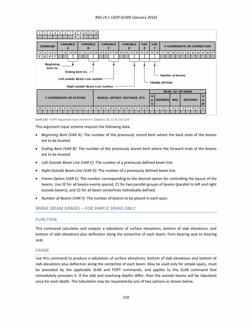
BGS v9.1 USER GUIDE (January 2016)
210
Card 115 - FOPT Argument Input Scheme F (Options 20, 21 & 22) Card
This argument input scheme requires the following data:
Beginning Bent (VAR A): The number of the previously stored bent where the back ends of the beams
are to be located.
Ending Bent (VAR B): The number of the previously stored bent where the forward ends of the beams
are to be located.
Left Outside Beam Line (VAR C): The number of a previously defined beam line.
Right Outside Beam Line (VAR D): The number of a previously defined beam line.
Frame Option (VAR E): The number corresponding to the desired option for controlling the layout of the
beams. Use 20 for all beams evenly spaced, 21 for two parallel groups of beams (parallel to left and right
outside beams), and 22 for all beam centerlines individually defined.
Number of Beams (VAR F): The number of beams to be placed in each span.
BMGD (BEAM GRADE) – FOR SIMPLE SPANS ONLY
FUNCTION
This command calculates and outputs a tabulation of surface elevations, bottom of slab elevations, and
bottom of slab elevations plus deflection along the centerline of each beam, from bearing seat to bearing
seat.
USAGE
Use this command to produce a tabulation of surface elevations, bottom of slab elevations and bottom of
slab elevations plus deflection along the centerline of each beam. May be used only for simple spans, must
be preceded by the applicable SLAB and FOPT commands, and applies to the SLAB command that
immediately precedes it. If the slab and overhang depths differ, then the outside beams will be tabulated
once for each depth. This tabulation may be requested by one of two options as shown below.
1 2 3 4 5 6 7 8 9 10 11 12
R G
13 14 15 16 17 18 19 20 21 22 23 24 25 26 27 28 29 30 31 32 33 34 35 36 37 38 39 40 41 42 43 44 45 46 47
F O P T
Beginning
bent no.
Ending bent no.
Number of beams
Left outside Beam Line number
FRAME OPTION
Right outside Beam Line number
N
or
S
E
or
W
48 49 50 51 52 53 54 55 56 57 58 59 60 61 62 63 64 65 66 67 68 69 70 71 72 73 74 75 76 77 78 79 80
VARIABLE
ACOMMAND
Y COORDINATE OR STATION
VAR.
FX COORDINATE OR CORRECTION
SECONDSMIN.DEGREES
BEAR, AZ, OR SKEW
RADIUS, OFFSET, DISTANCE, ETC.
VAR.
E
VARIABLE
D
VARIABLE
C
VARIABLE
B
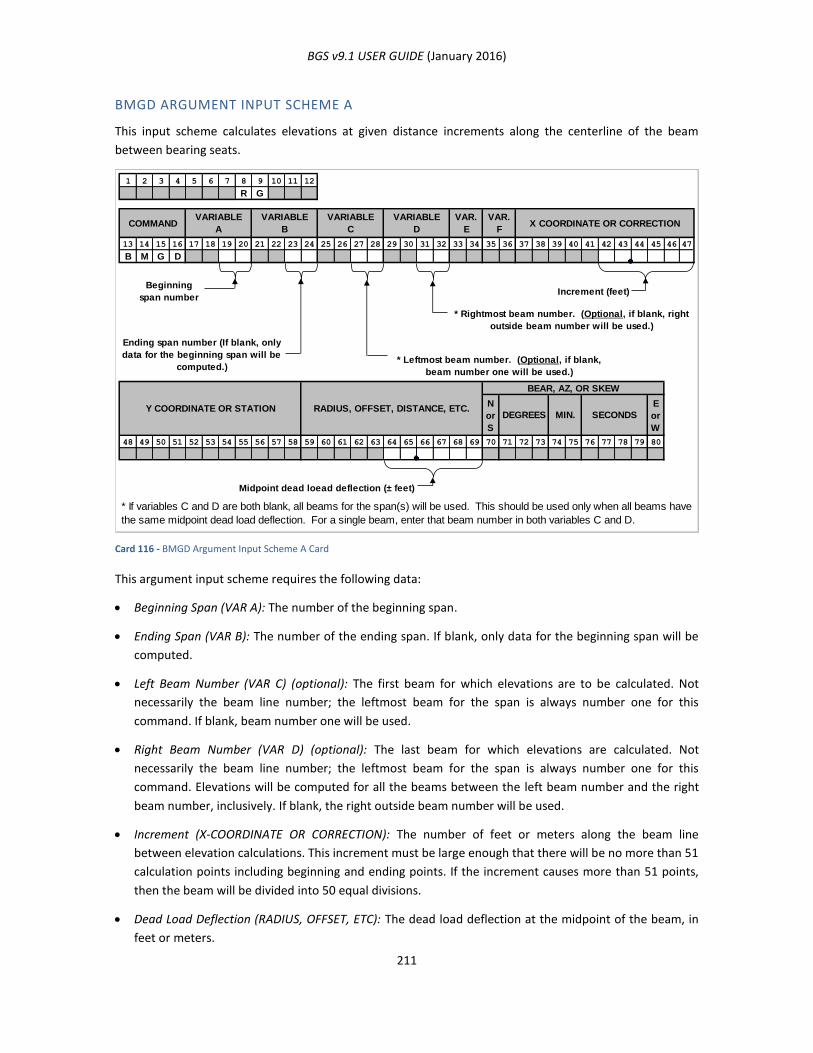
BGS v9.1 USER GUIDE (January 2016)
211
BMGD ARGUMENT INPUT SCHEME A
This input scheme calculates elevations at given distance increments along the centerline of the beam
between bearing seats.
Card 116 - BMGD Argument Input Scheme A Card
This argument input scheme requires the following data:
Beginning Span (VAR A): The number of the beginning span.
Ending Span (VAR B): The number of the ending span. If blank, only data for the beginning span will be
computed.
Left Beam Number (VAR C) (optional): The first beam for which elevations are to be calculated. Not
necessarily the beam line number; the leftmost beam for the span is always number one for this
command. If blank, beam number one will be used.
Right Beam Number (VAR D) (optional): The last beam for which elevations are calculated. Not
necessarily the beam line number; the leftmost beam for the span is always number one for this
command. Elevations will be computed for all the beams between the left beam number and the right
beam number, inclusively. If blank, the right outside beam number will be used.
Increment (X-COORDINATE OR CORRECTION): The number of feet or meters along the beam line
between elevation calculations. This increment must be large enough that there will be no more than 51
calculation points including beginning and ending points. If the increment causes more than 51 points,
then the beam will be divided into 50 equal divisions.
Dead Load Deflection (RADIUS, OFFSET, ETC): The dead load deflection at the midpoint of the beam, in
feet or meters.
1 2 3 4 5 6 7 8 9 10 11 12
R G
13 14 15 16 17 18 19 20 21 22 23 24 25 26 27 28 29 30 31 32 33 34 35 36 37 38 39 40 41 42 43 44 45 46 47
B M G D
Beginning
span numberIncrement (feet)
* Rightmost beam number. (Optional, if blank, right
outside beam number will be used.)
Ending span number (If blank, only
data for the beginning span will be
computed.)* Leftmost beam number. (Optional, if blank,
beam number one will be used.)
N
or
S
E
or
W
48 49 50 51 52 53 54 55 56 57 58 59 60 61 62 63 64 65 66 67 68 69 70 71 72 73 74 75 76 77 78 79 80
Midpoint dead loead deflection (± feet)
* If variables C and D are both blank, all beams for the span(s) will be used. This should be used only when all beams have
the same midpoint dead load deflection. For a single beam, enter that beam number in both variables C and D.
VAR.
FX COORDINATE OR CORRECTION
SECONDS
COMMANDVARIABLE
A
VARIABLE
B
VARIABLE
C
VARIABLE
D
VAR.
E
Y COORDINATE OR STATIONMIN.DEGREES
BEAR, AZ, OR SKEW
RADIUS, OFFSET, DISTANCE, ETC.
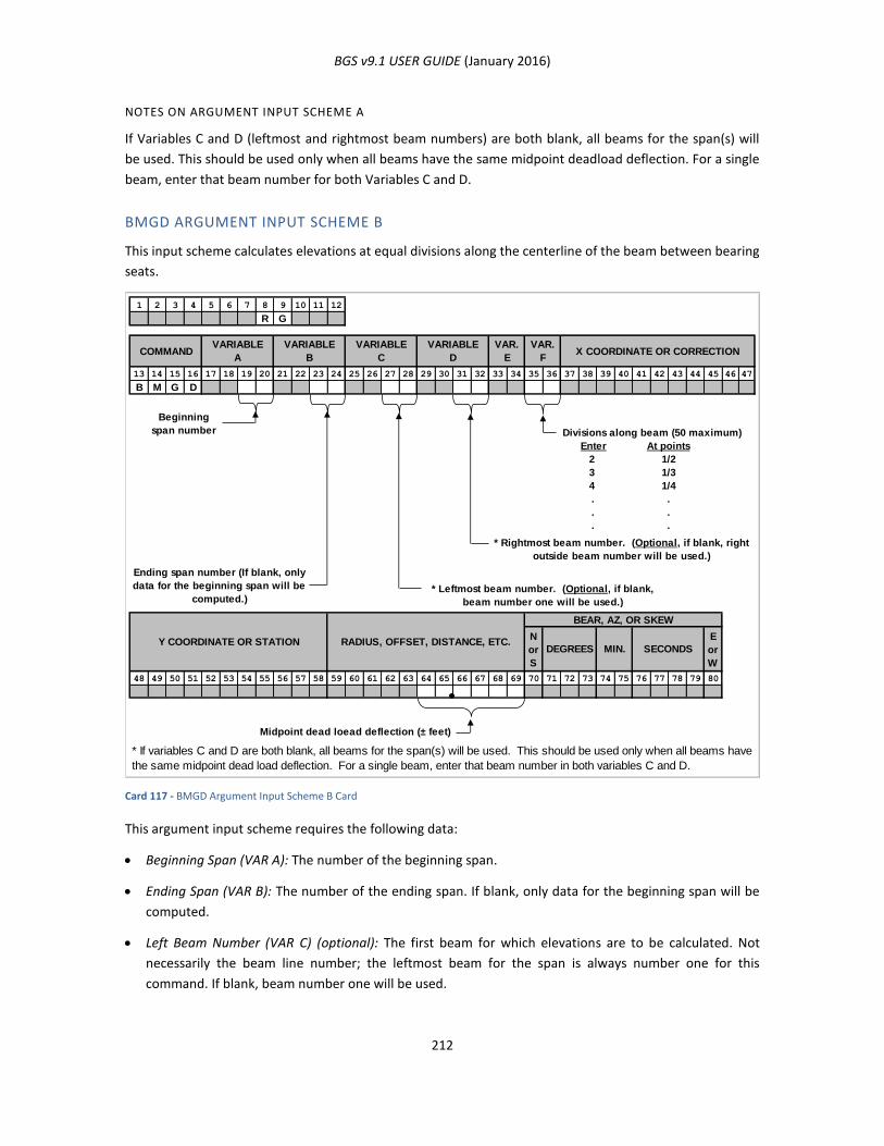
BGS v9.1 USER GUIDE (January 2016)
212
NOTES ON ARGUMENT INPUT SCHEME A
If Variables C and D (leftmost and rightmost beam numbers) are both blank, all beams for the span(s) will
be used. This should be used only when all beams have the same midpoint deadload deflection. For a single
beam, enter that beam number for both Variables C and D.
BMGD ARGUMENT INPUT SCHEME B
This input scheme calculates elevations at equal divisions along the centerline of the beam between bearing
seats.
Card 117 - BMGD Argument Input Scheme B Card
This argument input scheme requires the following data:
Beginning Span (VAR A): The number of the beginning span.
Ending Span (VAR B): The number of the ending span. If blank, only data for the beginning span will be
computed.
Left Beam Number (VAR C) (optional): The first beam for which elevations are to be calculated. Not
necessarily the beam line number; the leftmost beam for the span is always number one for this
command. If blank, beam number one will be used.
1 2 3 4 5 6 7 8 9 10 11 12
R G
13 14 15 16 17 18 19 20 21 22 23 24 25 26 27 28 29 30 31 32 33 34 35 36 37 38 39 40 41 42 43 44 45 46 47
B M G D
Beginning
span number Divisions along beam (50 maximum)
Enter At points
2
3
4
.
.
.
* Rightmost beam number. (Optional, if blank, right
outside beam number will be used.)
Ending span number (If blank, only
data for the beginning span will be
computed.)* Leftmost beam number. (Optional, if blank,
beam number one will be used.)
N
or
S
E
or
W
48 49 50 51 52 53 54 55 56 57 58 59 60 61 62 63 64 65 66 67 68 69 70 71 72 73 74 75 76 77 78 79 80
Midpoint dead loead deflection (± feet)
MIN.
BEAR, AZ, OR SKEW
RADIUS, OFFSET, DISTANCE, ETC.SECONDS
Y COORDINATE OR STATION
1/4
VARIABLE
B
VARIABLE
D
VAR.
E
VAR.
FX COORDINATE OR CORRECTION
.
DEGREES
VARIABLE
CCOMMAND
VARIABLE
A
* If variables C and D are both blank, all beams for the span(s) will be used. This should be used only when all beams have
the same midpoint dead load deflection. For a single beam, enter that beam number in both variables C and D.
.
.
1/2
1/3
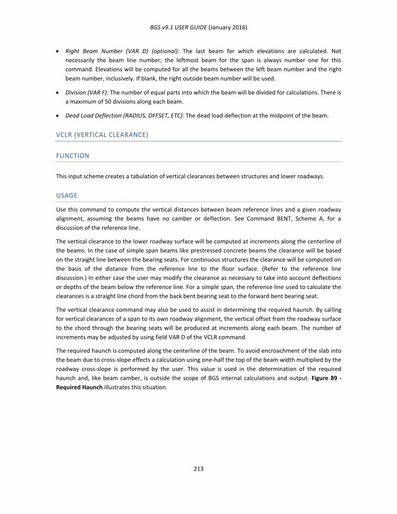
BGS v9.1 USER GUIDE (January 2016)
213
Right Beam Number (VAR D) (optional): The last beam for which elevations are calculated. Not
necessarily the beam line number; the leftmost beam for the span is always number one for this
command. Elevations will be computed for all the beams between the left beam number and the right
beam number, inclusively. If blank, the right outside beam number will be used.
Division (VAR F): The number of equal parts into which the beam will be divided for calculations. There is
a maximum of 50 divisions along each beam.
Dead Load Deflection (RADIUS, OFFSET, ETC): The dead load deflection at the midpoint of the beam.
VCLR (VERTICAL CLEARANCE)
FUNCTION
This input scheme creates a tabulation of vertical clearances between structures and lower roadways.
USAGE
Use this command to compute the vertical distances between beam reference lines and a given roadway
alignment, assuming the beams have no camber or deflection. See Command BENT, Scheme A, for a
discussion of the reference line.
The vertical clearance to the lower roadway surface will be computed at increments along the centerline of
the beams. In the case of simple span beams like prestressed concrete beams the clearance will be based
on the straight line between the bearing seats. For continuous structures the clearance will be computed on
the basis of the distance from the reference line to the floor surface. (Refer to the reference line
discussion.) In either case the user may modify the clearance as necessary to take into account deflections
or depths of the beam below the reference line. For a simple span, the reference line used to calculate the
clearances is a straight line chord from the back bent bearing seat to the forward bent bearing seat.
The vertical clearance command may also be used to assist in determining the required haunch. By calling
for vertical clearances of a span to its own roadway alignment, the vertical offset from the roadway surface
to the chord through the bearing seats will be produced at increments along each beam. The number of
increments may be adjusted by using field VAR D of the VCLR command.
The required haunch is computed along the centerline of the beam. To avoid encroachment of the slab into
the beam due to cross-slope effects a calculation using one-half the top of the beam width multiplied by the
roadway cross-slope is performed by the user. This value is used in the determination of the required
haunch and, like beam camber, is outside the scope of BGS internal calculations and output. Figure 89 -
Required Haunch illustrates this situation.
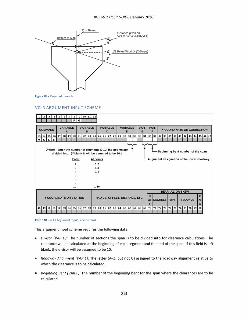
BGS v9.1 USER GUIDE (January 2016)
214
Figure 89 - Required Haunch
VCLR ARGUMENT INPUT SCHEME
Card 118 - VCLR Argument Input Scheme Card
This argument input scheme requires the following data:
Divisor (VAR D): The number of sections the span is to be divided into for clearance calculations. The
clearance will be calculated at the beginning of each segment and the end of the span. If this field is left
blank, the divisor will be assumed to be 10.
Roadway Alignment (VAR E): The letter (A–Z, but not G) assigned to the roadway alignment relative to
which the clearance is to be calculated.
Beginning Bent (VAR F): The number of the beginning bent for the span where the clearances are to be
calculated.
Bottom of Slab
C of BeamDistance given onVCLR output (Method A)
1/2 Beam Width X (X-Slope)
L
1 2 3 4 5 6 7 8 9 10 11 12
R G
13 14 15 16 17 18 19 20 21 22 23 24 25 26 27 28 29 30 31 32 33 34 35 36 37 38 39 40 41 42 43 44 45 46 47
V C L R
Divisor - Enter the number of segments (2-10) the beams are
divided into. (If blank it will be assumed to be 10.)Beginning bent number of the span
Enter At points Alignment designation of the lower roadway
2
3
4
.
.
.
10
N
or
S
E
or
W
48 49 50 51 52 53 54 55 56 57 58 59 60 61 62 63 64 65 66 67 68 69 70 71 72 73 74 75 76 77 78 79 80
SECONDSMIN.DEGREES
BEAR, AZ, OR SKEW
RADIUS, OFFSET, DISTANCE, ETC.
.
VAR.
F
.
VARIABLE
ACOMMAND X COORDINATE OR CORRECTION
VAR.
E
VARIABLE
D
VARIABLE
C
VARIABLE
B
.
Y COORDINATE OR STATION
1/10
1/2
1/3
1/4

BGS v9.1 USER GUIDE (January 2016)
215
NOTES ON VCLR COMMAND
Regardless of the depth below reference line used on the Bearing Command (BRNG), a careful analysis of
the relative differences in the tabular values given in the VCLR output will assist in detecting when beams
encroach into the slab due to sag vertical curves, slope transitions, horizontal curvature and/or
superelevation.
Calculations are based on a straight line between bearing seats. Any permanent cambers in beams or dead
load deflections due to slab, are not taken into account in the VCLR command. However, for total required
beam haunch, these values must be included in the calculations.
The three methods listed below may be used to determine the required haunch.
Method A. Enter zero deduct on the BRNG command.
Method B. Enter the anticipated haunch as deduct on the BRNG command.
Method C. Enter the total anticipated bearing seat deduct on the BRNG command.
These three methods and the associated outputs are illustrated in the following figures and tables:
Figure 90 - Method A: Enter Zero
0.0
00.0
0
0.0
2
0.0
30
.02
0.0
40
.02
0.0
50
.03
0.0
50.0
3
0.0
50.0
3
0.0
40.0
2
0.0
30.0
2
0.0
20.0
1
0.0
00
.00
Cord
Method A: Enter Zero Below line is: +Above line is: -
Beam #1
Beam #3
.5 pt. Line Parallel toRoadway Surface
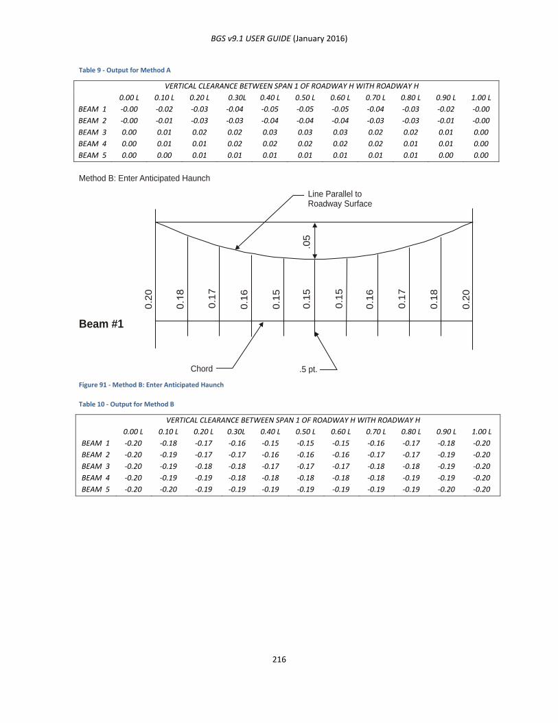
BGS v9.1 USER GUIDE (January 2016)
216
Table 9 - Output for Method A
VERTICAL CLEARANCE BETWEEN SPAN 1 OF ROADWAY H WITH ROADWAY H
BEAM 1
BEAM 2
BEAM 3
BEAM 4
BEAM 5
0.00 L
-0.00
-0.00
0.00
0.00
0.00
0.10 L
-0.02
-0.01
0.01
0.01
0.00
0.20 L
-0.03
-0.03
0.02
0.01
0.01
0.30L
-0.04
-0.03
0.02
0.02
0.01
0.40 L
-0.05
-0.04
0.03
0.02
0.01
0.50 L
-0.05
-0.04
0.03
0.02
0.01
0.60 L
-0.05
-0.04
0.03
0.02
0.01
0.70 L
-0.04
-0.03
0.02
0.02
0.01
0.80 L
-0.03
-0.03
0.02
0.01
0.01
0.90 L
-0.02
-0.01
0.01
0.01
0.00
1.00 L
-0.00
-0.00
0.00
0.00
0.00
Figure 91 - Method B: Enter Anticipated Haunch
Table 10 - Output for Method B
VERTICAL CLEARANCE BETWEEN SPAN 1 OF ROADWAY H WITH ROADWAY H
BEAM 1
BEAM 2
BEAM 3
BEAM 4
BEAM 5
0.00 L
-0.20
-0.20
-0.20
-0.20
-0.20
0.10 L
-0.18
-0.19
-0.19
-0.19
-0.20
0.20 L
-0.17
-0.17
-0.18
-0.19
-0.19
0.30L
-0.16
-0.17
-0.18
-0.18
-0.19
0.40 L
-0.15
-0.16
-0.17
-0.18
-0.19
0.50 L
-0.15
-0.16
-0.17
-0.18
-0.19
0.60 L
-0.15
-0.16
-0.17
-0.18
-0.19
0.70 L
-0.16
-0.17
-0.18
-0.18
-0.19
0.80 L
-0.17
-0.17
-0.18
-0.19
-0.19
0.90 L
-0.18
-0.19
-0.19
-0.19
-0.20
1.00 L
-0.20
-0.20
-0.20
-0.20
-0.20
0.2
0
0.1
7
0.1
6
0.1
5
0.1
5.0
5
0.1
5
0.1
6
0.1
7
0.1
8
0.2
0
Method B: Enter Anticipated Haunch
Beam #1
Line Parallel toRoadway Surface
Chord .5 pt.
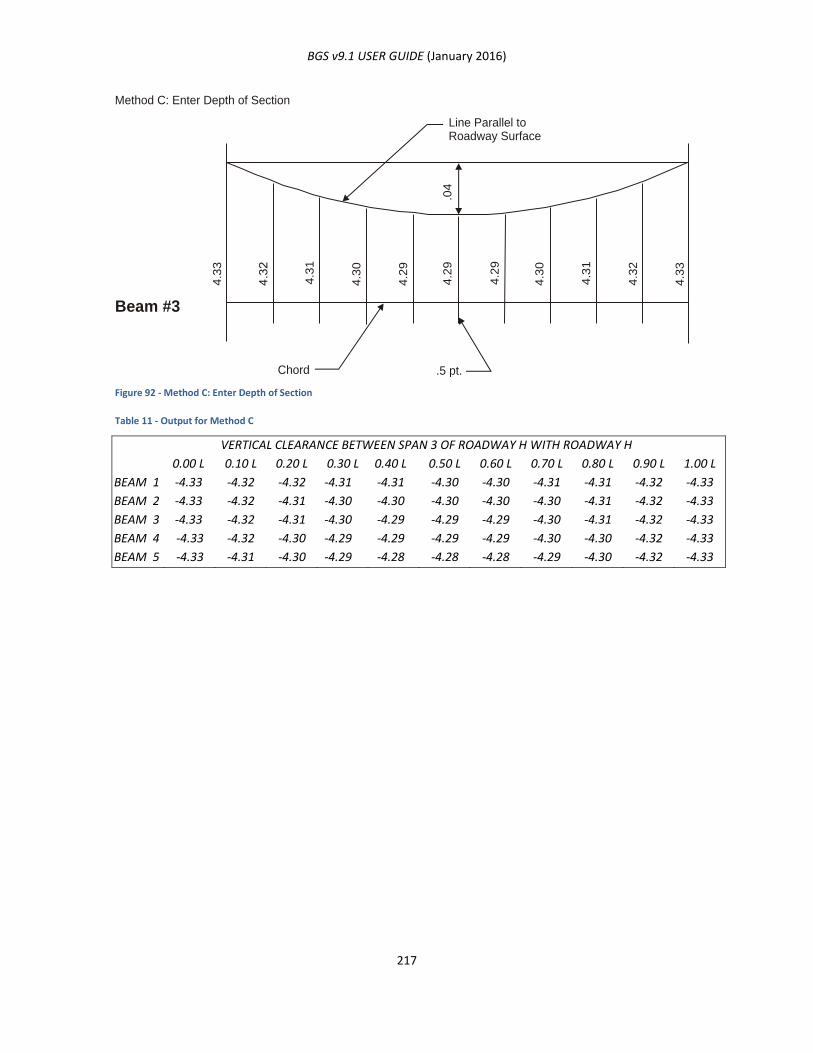
BGS v9.1 USER GUIDE (January 2016)
217
Figure 92 - Method C: Enter Depth of Section
Table 11 - Output for Method C
VERTICAL CLEARANCE BETWEEN SPAN 3 OF ROADWAY H WITH ROADWAY H
BEAM 1
BEAM 2
BEAM 3
BEAM 4
BEAM 5
0.00 L
-4.33
-4.33
-4.33
-4.33
-4.33
0.10 L
-4.32
-4.32
-4.32
-4.32
-4.31
0.20 L
-4.32
-4.31
-4.31
-4.30
-4.30
0.30 L
-4.31
-4.30
-4.30
-4.29
-4.29
0.40 L
-4.31
-4.30
-4.29
-4.29
-4.28
0.50 L
-4.30
-4.30
-4.29
-4.29
-4.28
0.60 L
-4.30
-4.30
-4.29
-4.29
-4.28
0.70 L
-4.31
-4.30
-4.30
-4.30
-4.29
0.80 L
-4.31
-4.31
-4.31
-4.30
-4.30
0.90 L
-4.32
-4.32
-4.32
-4.32
-4.32
1.00 L
-4.33
-4.33
-4.33
-4.33
-4.33
4.3
3
4.3
1
4.3
0
4.2
9
4.2
9.0
4
4.2
9
4.3
0
4.3
1
4.3
2
4.3
3
Method C: Enter Depth of Section
Beam #3
Line Parallel toRoadway Surface
Chord .5 pt.
BGS v9.1 USER GUIDE (January 2016)
218
CHAPTER 8: COMMAND STRUCTURED INPUT – PLOTTING
PLOTTING
Plotting in BGS is supported when requested by the user. BGS can generate a plot file that is converted to a
MicroStation “dgn” file and which will be automatically displaced using the MicroStation software installed
on the user’s machine. Only the full “stand-alone” version of MicroStation can be automatically invoked by
BGS.
GENERAL PLOTTING INSTRUCTIONS
The BGS generated plot will include all the alignments, bridge framing, slab edge elevations and any other
elements that the user specifies. Up to four different “line” colors (the legacy term used in the BGS input
scheme is “pen” color, referencing the instruments used when the target media for such plots was physical
white vellum or paper rather than an electronic file) may be used in a single plot. See the NPEN command
for instructions on using pens.
The AXIS command allows the user to establish a coordinate system and “plotting field” for the plot. The
limits of the plotting field are only applicable to the legacy system that plotted to physical media and so
may be ignored when using the current version of BGS which plots to an electronic file. An unlimited
number of points, lines, curves, titles, titles, alignments, areas, and bridge frames and slabs can be drawing
on this coordinate system. Another AXIS card can be specified and subsequent plot data plotted on the new
specified coordinate system.
The term “width” is a legacy term referring to the 33-inch dimension of the plotting media. The term
“length” is a legacy term referring to the dimension of the media taken in the orthogonal direction (i.e. the
roll direction). Since the “media” is no longer “paper” but electronic the length and width of the plot field
are unlimited.
HORIZONTAL ALIGNMENT PLOTTING
ORIENTING THE PLOT
When using BGS to create a plot file (graphics drawing) the user must first orient the plot. This is done by
defining a plot axis; that is, by supplying BGS with a plot bearing and a plot reference point. The user may
do this in one of two ways; by automatic orientation, using the APLT command, or by fixed orientation,
using the AXIS command. For the APLT command, the user specifies a horizontal alignment to be plotted.
BGS will automatically define the plot axis in such a way that the horizontal alignment is displayed across
the graphics screen, from the left side of the screen to the right side of the screen, in the direction of
increasing stations. All other plot data will be displayed on the screen in the proper relationship to the
specified horizontal alignment.
For the AXIS command, the user specifies the reference point and bearing. These should be chosen in such
a way that if a line at that bearing is drawn through a sketch of the plot data, and that sketch is rotated at
that bearing, the reference point lies near the upper left-hand corner of the rotated sketch. When the data
is plotted, it will appear on the screen in the same aspect as it did on the rotated sketch.

BGS v9.1 USER GUIDE (January 2016)
219
The APLT command is easier to use, but the AXIS command gives the user more control over how the data
is displayed. In either case, an arrow pointing to true north appears in the upper left-hand corner of the
graphics display.
The definition of the plot axis must precede all other plot commands; for example, CPLT, LABL, or PPLT
commands. If any of these commands precede the axis definition, BGS will ignore them. There is an
exception to this rule: the NPEN command. If the plot axis is being defined by an APLT command, an NPEN
command may precede it, and the APLT alignment will be plotted with the color specified by the NPEN
command.
For a plot being displayed on the graphics screen, there is no boundary to the display, beyond which items
or parts of items are omitted. In consequence, if the user defines an item at an extreme distance from the
horizontal alignment which defines the axis, or at an extreme distance from the AXIS reference point, the
graphics display will appear to consist of dots of color at opposite ends of the screen.
APLT (ALIGNMENT PLOT: MAY BE USED FOR AUTOMATIC ORIENTATION OF PLOT)
FUNCTION
This command produces an annotated plot of a roadway alignment that has been previously computed and
stored. If the first of a series of APLT cards does not immediately follow an AXIS card, BGS performs a linear
least-squares fit on the principal points (PIs, PTs, etc.) of the alignment. This produces a plot axis such that
the alignment runs across the screen from left to right in the direction of increasing stations. All plotting
instructions which occur between the current “First APLT” card and the next “First APLT” or AXIS card will
be plotted with reference to this axis.
USAGE
Use this command to establish a reference axis for all of the plotting to be done for one drawing. It also
produces an annotated plot of a roadway alignment that has been previously computed and stored. If a
supported version of MicroStation is resident, the plot will be displayed in MicroStation.

BGS v9.1 USER GUIDE (January 2016)
220
APLT ARGUMENT INPUT SCHEME
Card 119 - APLT Argument Input Scheme Card
The APLT argument input scheme requires the following data:
Axis/No Axis Flag: If a “1” is entered in this column, this alignment defines a new axis for the display.
This is a “First APLT” card. If this column is blank, this alignment is plotted on the most recent
previously-defined axis. (If this column is blank and there is no preceding AXIS or APLT card, then this
alignment defines an axis, and is a “First APLT” card.)
Tick Mark Distance (VAR C): The distance in feet or meters along the alignment between tick marks. If
station labels are desired, tick marks must be requested at a distance equal to or less than that of the
station labels, and the station label distance must be evenly divisible by the tick mark distance.
Station Label Distance (VAR D) (optional): The distance in feet or meters along the alignment between
station labels. If station labels and tick marks are both desired, the station label distance must be
coordinated with the tick mark distance.
Roadway Alignment (VAR E): The letter (A–Z) assigned to the alignment which is to be plotted.
Beginning Station (X-COORDINATE OR CORRECTION): The station on the roadway where the axis will
begin. If this field is blank, the first station on the roadway is used.
Ending Station (Y-COORDINATE OR STATION): The station on the roadway where the axis will end. If this
field is blank, the last station on the roadway is used.
DA1: If this field is not blank, all annotation other than station labels and tick marks is omitted.
1 2 3 4 5 6 7 8 9 10 11 12
R G
13 14 15 16 17 18 19 20 21 22 23 24 25 26 27 28 29 30 31 32 33 34 35 36 37 38 39 40 41 42 43 44 45 46 47
A P L T
Axis/No Axis Flag
Beginning station (If blank, first roadway station on the file is used.)
N
or
S
E
or
W
48 49 50 51 52 53 54 55 56 57 58 59 60 61 62 63 64 65 66 67 68 69 70 71 72 73 74 75 76 77 78 79 80
Character size
DA1DA2
DA3DA4
DA5
Scale Factor (If blank, scale is 1:1) **
Ending Station (If blank, last roadway station on the file is used.)
VARIABLE
ACOMMAND X COORDINATE OR CORRECTION
VAR.
F
VAR.
E
VARIABLE
D
VARIABLE
C
VARIABLE
B
** The Scale Factor is a legacy of the hard media plot days. Always plot 1 to 1 in "electronic media" (computer graphics files).
Distance in feet
between station labels
Distance in feet or meters between tic
marks (If blank, tics are omitted.)
Alignment
Letter (A - Z)
*Tic marks must be requested at an interval equal to or greater than that of the station labels. The station label intervals must
be divisible by the tic mark interval.
BEAR, AZ, OR SKEW
Y COORDINATE OR STATION RADIUS, OFFSET, DISTANCE, ETC.DEGREES MIN. SECONDS
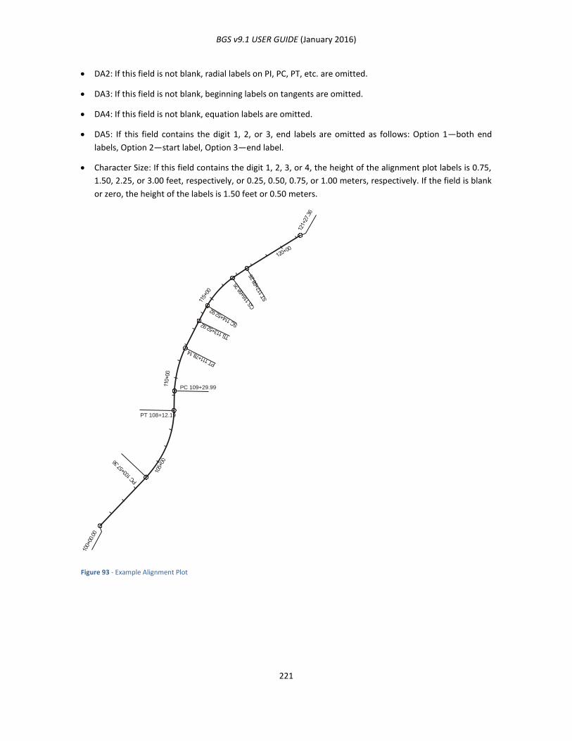
BGS v9.1 USER GUIDE (January 2016)
221
DA2: If this field is not blank, radial labels on PI, PC, PT, etc. are omitted.
DA3: If this field is not blank, beginning labels on tangents are omitted.
DA4: If this field is not blank, equation labels are omitted.
DA5: If this field contains the digit 1, 2, or 3, end labels are omitted as follows: Option 1—both end
labels, Option 2—start label, Option 3—end label.
Character Size: If this field contains the digit 1, 2, 3, or 4, the height of the alignment plot labels is 0.75,
1.50, 2.25, or 3.00 feet, respectively, or 0.25, 0.50, 0.75, or 1.00 meters, respectively. If the field is blank
or zero, the height of the labels is 1.50 feet or 0.50 meters.
Figure 93 - Example Alignment Plot
PC 109+29.99
PT 108+12.19

BGS v9.1 USER GUIDE (January 2016)
222
NOTES ON EXAMPLE ALIGNMENT PLOT
All the annotation appears on the plot of this alignment unless the user specifies that it is to be omitted.
The plot may be oriented on the screen in one of two ways:
Fixed Orientation: When the APLT command is preceded by an AXIS command, which provides the
coordinates of the upper left corner and the bearing of the plot axis.
Automatic Orientation: When the APLT command is not preceded by an AXIS command. The system
runs a linear least squares curve fit on the principal points (PIs, PTs, etc) of the alignment. This produces
a plot axis such that the alignment runs across the screen from left to right in the direction of increasing
stations. A north arrow indicates the true direction of the alignment.
Any succeeding APLT command will be plotted on the axis defined above unless a new axis is defined. A
new axis is defined by a subsequent AXIS command or by a subsequent APLT command with the digit 1
in column 20. The system will move the new axis to the right of the old, leaving a space between the
two.
Other plot data such as APLT, CPLT, LABL, or PPLT commands may follow the AXIS command or the
“First APLT” command, and will be plotted with reference to this axis.
AXIS (FIXED ORIENTATION OF PLOT)
FUNCTION
This command defines a new plot axis. If a plot axis has been previously defined by a prior AXIS command
or by a prior APLT command, the system moves to the right past the previous axis before establishing a new
axis. Other plot data such as a CPLT, LABL, or PPLT command may follow the AXIS command and will be
plotted with reference to the newly defined axis.
USAGE
Use this command to establish a reference axis for all of the plotting to be done for one drawing. The user
should choose this axis and a reference point in such a way that if a line at that bearing is drawn through a
sketch of the plot data, and that sketch is rotated at that bearing, the reference point lies near the upper
left-hand corner of the rotated sketch. When the data is plotted, it will appear on the screen in the same
aspect as it did on the rotated sketch. Each time an AXIS or a “First APLT” instruction is encountered, the
system moves to the right, past any previously displayed drawing, before establishing a new axis. All
plotting commands which occur between the current AXIS instruction and the next AXIS or “First APLT”
command will be plotted with reference to this axis. An illustration of the axis is given in Figure 94 -
Graphics Illustration.
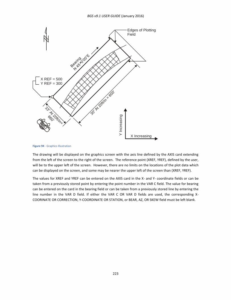
BGS v9.1 USER GUIDE (January 2016)
223
Figure 94 - Graphics Illustration
The drawing will be displayed on the graphics screen with the axis line defined by the AXIS card extending
from the left of the screen to the right of the screen. The reference point (XREF, YREF), defined by the user,
will be to the upper left of the screen. However, there are no limits on the locations of the plot data which
can be displayed on the screen, and some may be nearer the upper left of the screen than (XREF, YREF).
The values for XREF and YREF can be entered on the AXIS card in the X- and Y- coordinate fields or can be
taken from a previously stored point by entering the point number in the VAR C field. The value for bearing
can be entered on the card in the bearing field or can be taken from a previously stored line by entering the
line number in the VAR D field. If either the VAR C OR VAR D fields are used, the corresponding X-
COORINATE OR CORRECTION, Y-COORDINATE OR STATION, or BEAR, AZ, OR SKEW field must be left blank.
Edges of Plotting Field
X Increasing Y I
n c
r e a
s i n
g
X REF = 500 Y REF = 300
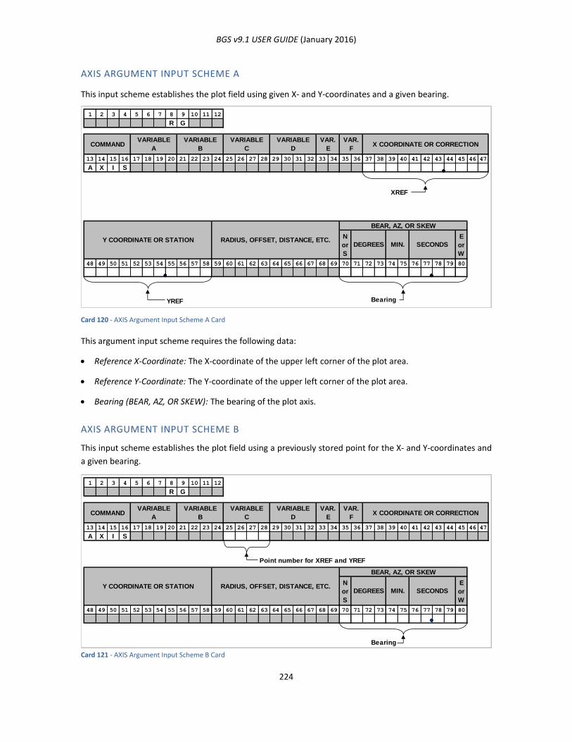
BGS v9.1 USER GUIDE (January 2016)
224
AXIS ARGUMENT INPUT SCHEME A
This input scheme establishes the plot field using given X- and Y-coordinates and a given bearing.
Card 120 - AXIS Argument Input Scheme A Card
This argument input scheme requires the following data:
Reference X-Coordinate: The X-coordinate of the upper left corner of the plot area.
Reference Y-Coordinate: The Y-coordinate of the upper left corner of the plot area.
Bearing (BEAR, AZ, OR SKEW): The bearing of the plot axis.
AXIS ARGUMENT INPUT SCHEME B
This input scheme establishes the plot field using a previously stored point for the X- and Y-coordinates and
a given bearing.
Card 121 - AXIS Argument Input Scheme B Card
1 2 3 4 5 6 7 8 9 10 11 12
R G
13 14 15 16 17 18 19 20 21 22 23 24 25 26 27 28 29 30 31 32 33 34 35 36 37 38 39 40 41 42 43 44 45 46 47
A X I S
XREF
N
or
S
E
or
W
48 49 50 51 52 53 54 55 56 57 58 59 60 61 62 63 64 65 66 67 68 69 70 71 72 73 74 75 76 77 78 79 80
YREF Bearing
VARIABLE
D
VAR.
E
VAR.
FX COORDINATE OR CORRECTIONCOMMAND
VARIABLE
A
VARIABLE
B
VARIABLE
C
RADIUS, OFFSET, DISTANCE, ETC.Y COORDINATE OR STATIONSECONDSMIN.DEGREES
BEAR, AZ, OR SKEW
1 2 3 4 5 6 7 8 9 10 11 12
R G
13 14 15 16 17 18 19 20 21 22 23 24 25 26 27 28 29 30 31 32 33 34 35 36 37 38 39 40 41 42 43 44 45 46 47
A X I S
Point number for XREF and YREF
N
or
S
E
or
W
48 49 50 51 52 53 54 55 56 57 58 59 60 61 62 63 64 65 66 67 68 69 70 71 72 73 74 75 76 77 78 79 80
Bearing
VARIABLE
D
VAR.
E
VAR.
FX COORDINATE OR CORRECTIONCOMMAND
VARIABLE
A
VARIABLE
B
VARIABLE
C
RADIUS, OFFSET, DISTANCE, ETC.Y COORDINATE OR STATIONSECONDSMIN.DEGREES
BEAR, AZ, OR SKEW
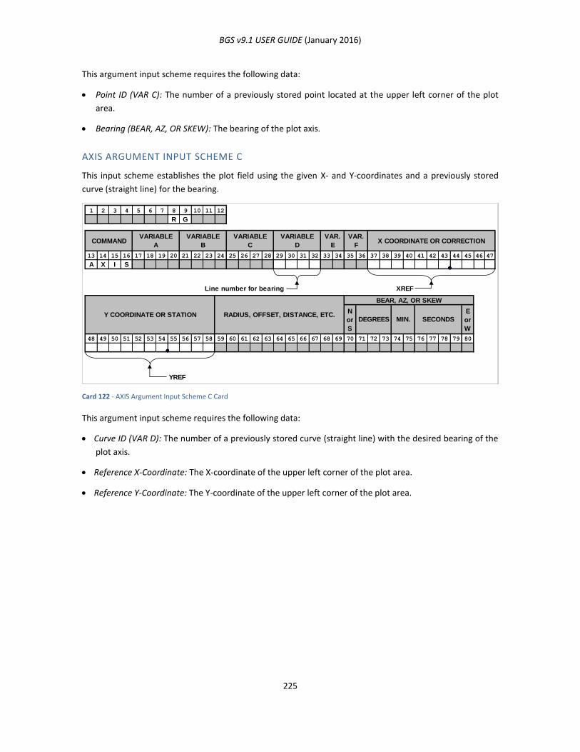
BGS v9.1 USER GUIDE (January 2016)
225
This argument input scheme requires the following data:
Point ID (VAR C): The number of a previously stored point located at the upper left corner of the plot
area.
Bearing (BEAR, AZ, OR SKEW): The bearing of the plot axis.
AXIS ARGUMENT INPUT SCHEME C
This input scheme establishes the plot field using the given X- and Y-coordinates and a previously stored
curve (straight line) for the bearing.
Card 122 - AXIS Argument Input Scheme C Card
This argument input scheme requires the following data:
Curve ID (VAR D): The number of a previously stored curve (straight line) with the desired bearing of the
plot axis.
Reference X-Coordinate: The X-coordinate of the upper left corner of the plot area.
Reference Y-Coordinate: The Y-coordinate of the upper left corner of the plot area.
1 2 3 4 5 6 7 8 9 10 11 12
R G
13 14 15 16 17 18 19 20 21 22 23 24 25 26 27 28 29 30 31 32 33 34 35 36 37 38 39 40 41 42 43 44 45 46 47
A X I S
Line number for bearing XREF
N
or
S
E
or
W
48 49 50 51 52 53 54 55 56 57 58 59 60 61 62 63 64 65 66 67 68 69 70 71 72 73 74 75 76 77 78 79 80
YREF
VARIABLE
D
VAR.
E
VAR.
FX COORDINATE OR CORRECTIONCOMMAND
VARIABLE
A
VARIABLE
B
VARIABLE
C
RADIUS, OFFSET, DISTANCE, ETC.Y COORDINATE OR STATIONSECONDSMIN.DEGREES
BEAR, AZ, OR SKEW
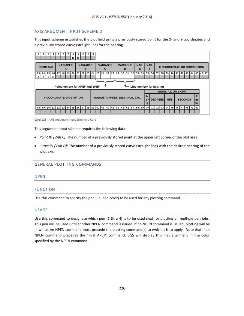
BGS v9.1 USER GUIDE (January 2016)
226
AXIS ARGUMENT INPUT SCHEME D
This input scheme establishes the plot field using a previously stored point for the X- and Y-coordinates and
a previously stored curve (straight line) for the bearing.
Card 123 - AXIS Argument Input Scheme D Card
This argument input scheme requires the following data:
Point ID (VAR C): The number of a previously stored point at the upper left corner of the plot area.
Curve ID (VAR D): The number of a previously stored curve (straight line) with the desired bearing of the
plot axis.
GENERAL PLOTTING COMMANDS
NPEN
FUNCTION
Use this command to specify the pen (i.e. pen color) to be used for any plotting command.
USAGE
Use this command to designate which pen (1 thru 4) is to be used next for plotting on multiple pen jobs.
This pen will be used until another NPEN command is issued. If no NPEN command is issued, plotting will be
in white. An NPEN command must precede the plotting command(s) to which it is to apply. Note that if an
NPEN command precedes the “First APLT” command, BGS will display this first alignment in the color
specified by the NPEN command.
1 2 3 4 5 6 7 8 9 10 11 12
R G
13 14 15 16 17 18 19 20 21 22 23 24 25 26 27 28 29 30 31 32 33 34 35 36 37 38 39 40 41 42 43 44 45 46 47
A X I S
Point number for XREF and YREF Line number for bearing
N
or
S
E
or
W
48 49 50 51 52 53 54 55 56 57 58 59 60 61 62 63 64 65 66 67 68 69 70 71 72 73 74 75 76 77 78 79 80
VARIABLE
D
VAR.
E
VAR.
FX COORDINATE OR CORRECTIONCOMMAND
VARIABLE
A
VARIABLE
B
VARIABLE
C
RADIUS, OFFSET, DISTANCE, ETC.Y COORDINATE OR STATION
BEAR, AZ, OR SKEW
SECONDSMIN.DEGREES
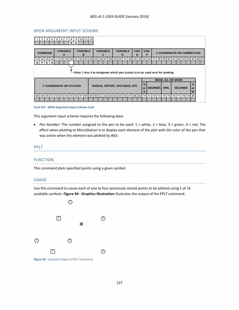
BGS v9.1 USER GUIDE (January 2016)
227
NPEN ARGUMENT INPUT SCHEME
Card 124 - NPEN Argument Input Scheme Card
This argument input scheme requires the following data:
Pen Number: The number assigned to the pen to be used: 1 = white, 2 = blue, 3 = green, 4 = red. The
effect when plotting to MicroStation is to display each element of the plot with the color of the pen that
was active when the element was plotted by BGS.
PPLT
FUNCTION
This command plots specified points using a given symbol.
USAGE
Use this command to cause each of one to four previously stored points to be plotted using 1 of 16
available symbols. Figure 94 - Graphics Illustration illustrates the output of the PPLT command.
Figure 95 - Example Output of PPLT Command
1 2 3 4 5 6 7 8 9 10 11 12
R G
13 14 15 16 17 18 19 20 21 22 23 24 25 26 27 28 29 30 31 32 33 34 35 36 37 38 39 40 41 42 43 44 45 46 47
N P E N
Enter 1 thru 4 to designate which pen (color) is to be used next for plotting.
N
or
S
E
or
W
48 49 50 51 52 53 54 55 56 57 58 59 60 61 62 63 64 65 66 67 68 69 70 71 72 73 74 75 76 77 78 79 80
COMMANDVARIABLE
A
VARIABLE
B
VARIABLE
C
VARIABLE
D
VAR.
E
VAR.
FX COORDINATE OR CORRECTION
RADIUS, OFFSET, DISTANCE, ETC.Y COORDINATE OR STATIONSECONDSMIN.DEGREES
BEAR, AZ, OR SKEW
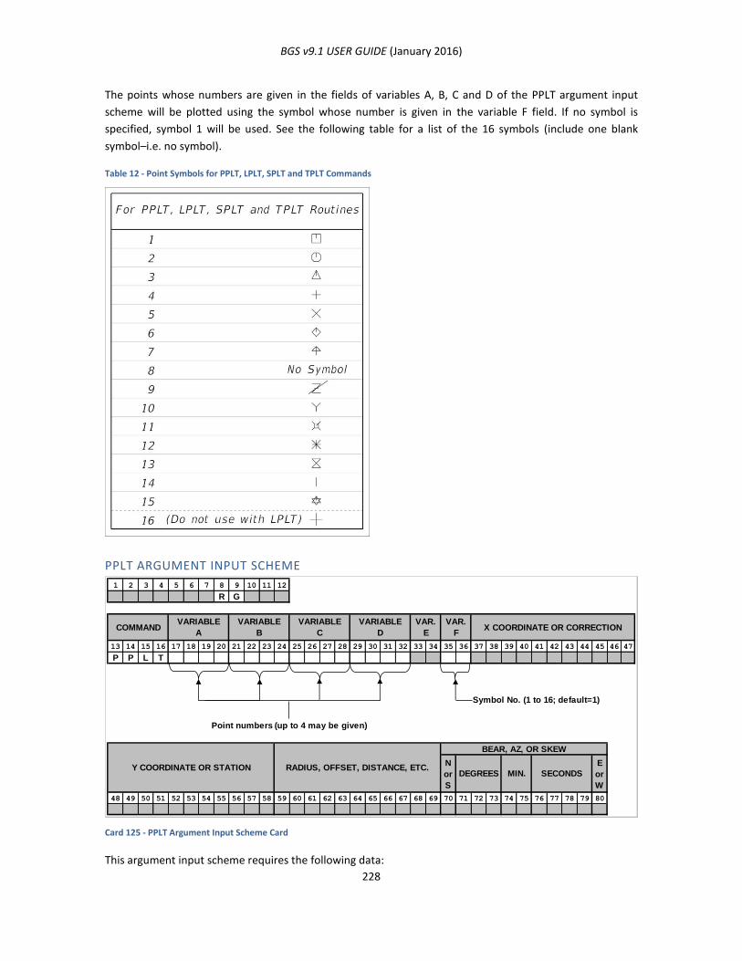
BGS v9.1 USER GUIDE (January 2016)
228
The points whose numbers are given in the fields of variables A, B, C and D of the PPLT argument input
scheme will be plotted using the symbol whose number is given in the variable F field. If no symbol is
specified, symbol 1 will be used. See the following table for a list of the 16 symbols (include one blank
symbol–i.e. no symbol).
Table 12 - Point Symbols for PPLT, LPLT, SPLT and TPLT Commands
PPLT ARGUMENT INPUT SCHEME
Card 125 - PPLT Argument Input Scheme Card
This argument input scheme requires the following data:
1 2 3 4 5 6 7 8 9 10 11 12
R G
13 14 15 16 17 18 19 20 21 22 23 24 25 26 27 28 29 30 31 32 33 34 35 36 37 38 39 40 41 42 43 44 45 46 47
P P L T
Symbol No. (1 to 16; default=1)
Point numbers (up to 4 may be given)
N
or
S
E
or
W
48 49 50 51 52 53 54 55 56 57 58 59 60 61 62 63 64 65 66 67 68 69 70 71 72 73 74 75 76 77 78 79 80
VARIABLE
ACOMMAND X COORDINATE OR CORRECTION
VAR.
F
VAR.
E
VARIABLE
D
VARIABLE
C
VARIABLE
B
Y COORDINATE OR STATION RADIUS, OFFSET, DISTANCE, ETC.DEGREES MIN.
BEAR, AZ, OR SKEW
SECONDS
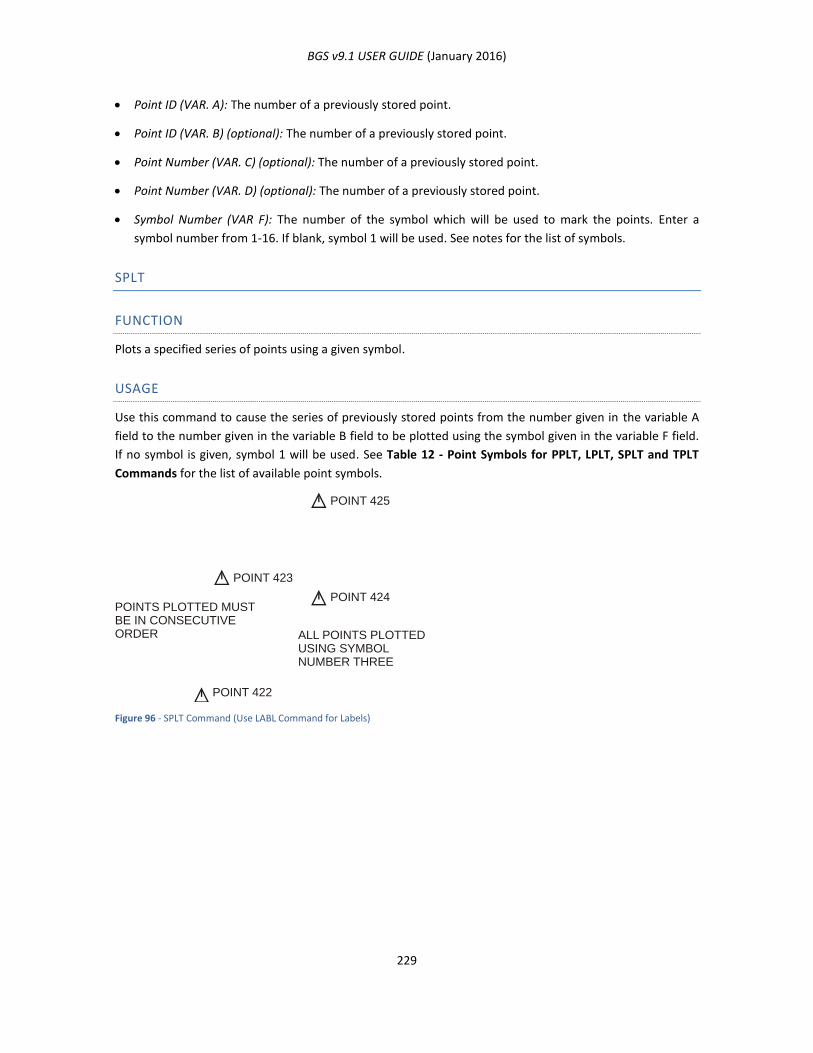
BGS v9.1 USER GUIDE (January 2016)
229
Point ID (VAR. A): The number of a previously stored point.
Point ID (VAR. B) (optional): The number of a previously stored point.
Point Number (VAR. C) (optional): The number of a previously stored point.
Point Number (VAR. D) (optional): The number of a previously stored point.
Symbol Number (VAR F): The number of the symbol which will be used to mark the points. Enter a
symbol number from 1-16. If blank, symbol 1 will be used. See notes for the list of symbols.
SPLT
FUNCTION
Plots a specified series of points using a given symbol.
USAGE
Use this command to cause the series of previously stored points from the number given in the variable A
field to the number given in the variable B field to be plotted using the symbol given in the variable F field.
If no symbol is given, symbol 1 will be used. See Table 12 - Point Symbols for PPLT, LPLT, SPLT and TPLT
Commands for the list of available point symbols.
Figure 96 - SPLT Command (Use LABL Command for Labels)
POINT 425
POINT 423
POINTS PLOTTED MUSTBE IN CONSECUTIVEORDER ALL POINTS PLOTTED
USING SYMBOLNUMBER THREE
POINT 424
POINT 422
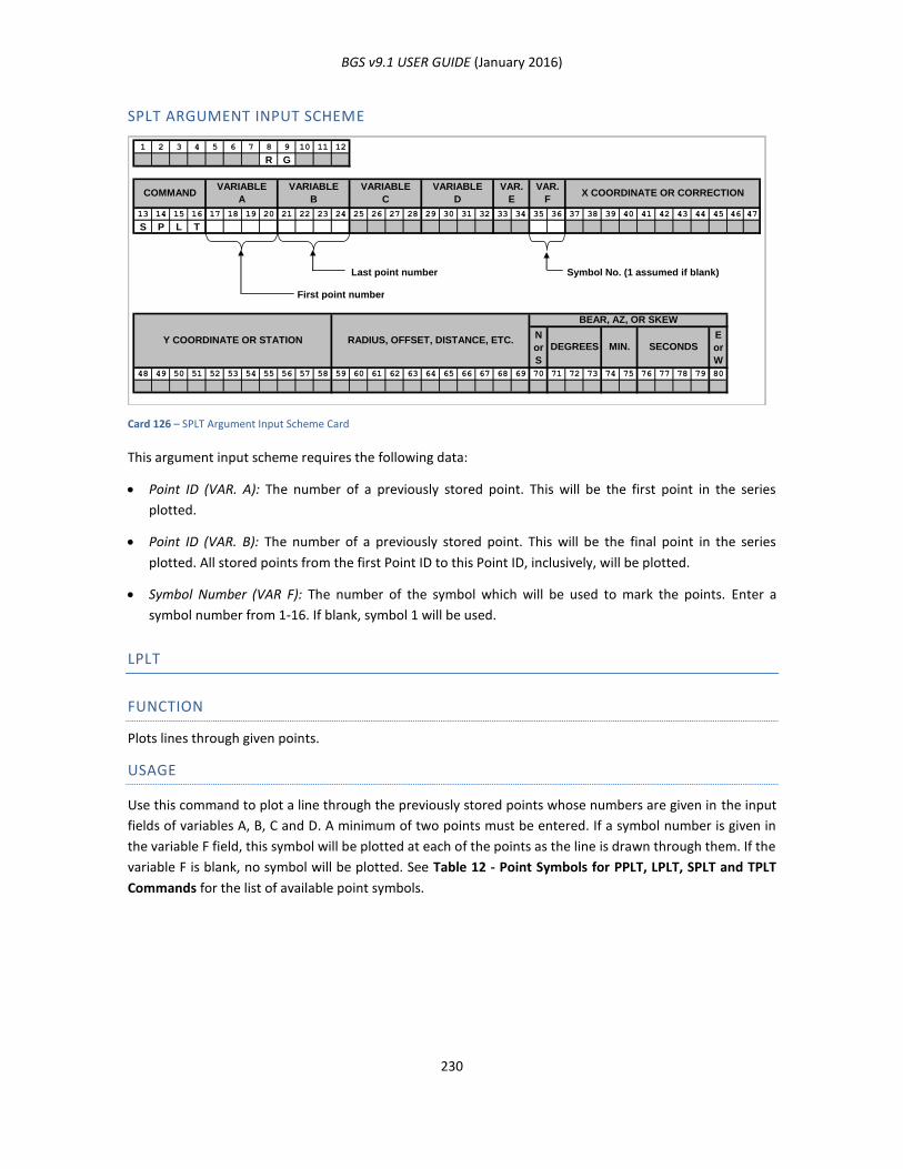
BGS v9.1 USER GUIDE (January 2016)
230
SPLT ARGUMENT INPUT SCHEME
Card 126 – SPLT Argument Input Scheme Card
This argument input scheme requires the following data:
Point ID (VAR. A): The number of a previously stored point. This will be the first point in the series
plotted.
Point ID (VAR. B): The number of a previously stored point. This will be the final point in the series
plotted. All stored points from the first Point ID to this Point ID, inclusively, will be plotted.
Symbol Number (VAR F): The number of the symbol which will be used to mark the points. Enter a
symbol number from 1-16. If blank, symbol 1 will be used.
LPLT
FUNCTION
Plots lines through given points.
USAGE
Use this command to plot a line through the previously stored points whose numbers are given in the input
fields of variables A, B, C and D. A minimum of two points must be entered. If a symbol number is given in
the variable F field, this symbol will be plotted at each of the points as the line is drawn through them. If the
variable F is blank, no symbol will be plotted. See Table 12 - Point Symbols for PPLT, LPLT, SPLT and TPLT
Commands for the list of available point symbols.
1 2 3 4 5 6 7 8 9 10 11 12
R G
13 14 15 16 17 18 19 20 21 22 23 24 25 26 27 28 29 30 31 32 33 34 35 36 37 38 39 40 41 42 43 44 45 46 47
S P L T
Last point number Symbol No. (1 assumed if blank)
First point number
N
or
S
E
or
W
48 49 50 51 52 53 54 55 56 57 58 59 60 61 62 63 64 65 66 67 68 69 70 71 72 73 74 75 76 77 78 79 80
RADIUS, OFFSET, DISTANCE, ETC.Y COORDINATE OR STATIONSECONDSMIN.DEGREES
BEAR, AZ, OR SKEW
COMMANDVARIABLE
A
VARIABLE
B
VARIABLE
C
VARIABLE
D
VAR.
E
VAR.
FX COORDINATE OR CORRECTION
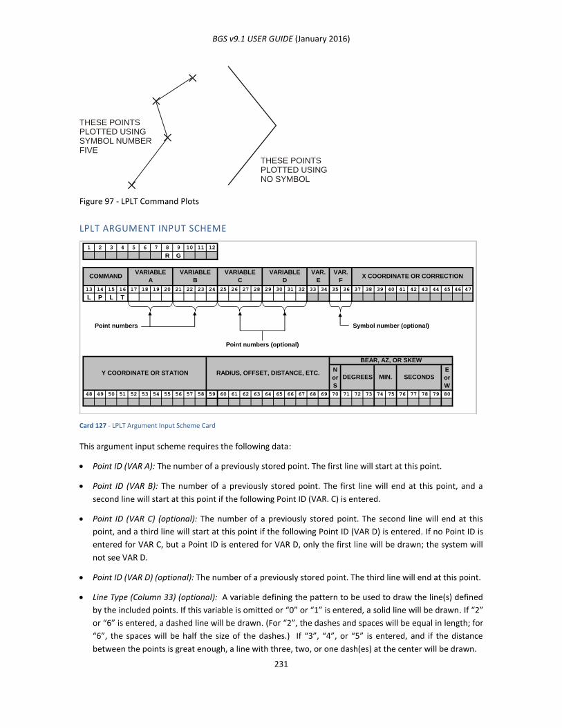
BGS v9.1 USER GUIDE (January 2016)
231
Figure 97 - LPLT Command Plots
LPLT ARGUMENT INPUT SCHEME
Card 127 - LPLT Argument Input Scheme Card
This argument input scheme requires the following data:
Point ID (VAR A): The number of a previously stored point. The first line will start at this point.
Point ID (VAR B): The number of a previously stored point. The first line will end at this point, and a
second line will start at this point if the following Point ID (VAR. C) is entered.
Point ID (VAR C) (optional): The number of a previously stored point. The second line will end at this
point, and a third line will start at this point if the following Point ID (VAR D) is entered. If no Point ID is
entered for VAR C, but a Point ID is entered for VAR D, only the first line will be drawn; the system will
not see VAR D.
Point ID (VAR D) (optional): The number of a previously stored point. The third line will end at this point.
Line Type (Column 33) (optional): A variable defining the pattern to be used to draw the line(s) defined
by the included points. If this variable is omitted or “0” or “1” is entered, a solid line will be drawn. If “2”
or “6” is entered, a dashed line will be drawn. (For “2”, the dashes and spaces will be equal in length; for
“6”, the spaces will be half the size of the dashes.) If “3”, “4”, or “5” is entered, and if the distance
between the points is great enough, a line with three, two, or one dash(es) at the center will be drawn.
THESE POINTSPLOTTED USINGSYMBOL NUMBERFIVE
THESE POINTSPLOTTED USINGNO SYMBOL
1 2 3 4 5 6 7 8 9 10 11 12
R G
13 14 15 16 17 18 19 20 21 22 23 24 25 26 27 28 29 30 31 32 33 34 35 36 37 38 39 40 41 42 43 44 45 46 47
L P L T
Point numbers Symbol number (optional)
Point numbers (optional)
N
or
S
E
or
W
48 49 50 51 52 53 54 55 56 57 58 59 60 61 62 63 64 65 66 67 68 69 70 71 72 73 74 75 76 77 78 79 80
RADIUS, OFFSET, DISTANCE, ETC.Y COORDINATE OR STATION
BEAR, AZ, OR SKEW
SECONDSMIN.DEGREES
COMMANDVARIABLE
A
VARIABLE
B
VARIABLE
C
VARIABLE
D
VAR.
E
VAR.
FX COORDINATE OR CORRECTION
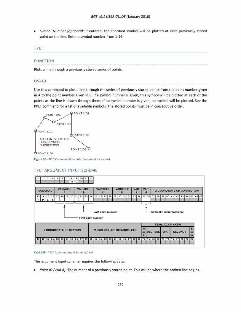
BGS v9.1 USER GUIDE (January 2016)
232
Symbol Number (optional): If entered, the specified symbol will be plotted at each previously stored
point on the line. Enter a symbol number from 1-16.
TPLT
FUNCTION
Plots a line through a previously stored series of points.
USAGE
Use this command to plot a line through the series of previously stored points from the point number given
in A to the point number given in B. If a symbol number is given, this symbol will be plotted at each of the
points as the line is drawn through them; if no symbol number is given, no symbol will be plotted. See the
PPLT command for a list of available symbols. The stored points must be in consecutive order.
Figure 98 - TPLT Command (Use LABL Command for Labels)
TPLT ARGUMENT INPUT SCHEME
Card 128 - TPLT Argument Input Scheme Card
This argument input scheme requires the following data:
Point ID (VAR A): The number of a previously stored point. This will be where the broken line begins.
ALL POINTS PLOTTEDUSING SYMBOLNUMBER TWO
POINT 1104POINT 1102
POINT 1103
POINT 1101
POINT 1100
POINT 1105
POINT 1106
1 2 3 4 5 6 7 8 9 10 11 12
R G
13 14 15 16 17 18 19 20 21 22 23 24 25 26 27 28 29 30 31 32 33 34 35 36 37 38 39 40 41 42 43 44 45 46 47
T P L T
Last point number Symbol Number (optional)
First point number
N
or
S
E
or
W
48 49 50 51 52 53 54 55 56 57 58 59 60 61 62 63 64 65 66 67 68 69 70 71 72 73 74 75 76 77 78 79 80
COMMAND
SECONDSMIN.DEGREES
BEAR, AZ, OR SKEW
RADIUS, OFFSET, DISTANCE, ETC.Y COORDINATE OR STATION
VARIABLE
D
VARIABLE
C
VARIABLE
B
VARIABLE
AX COORDINATE OR CORRECTION
VAR.
F
VAR.
E
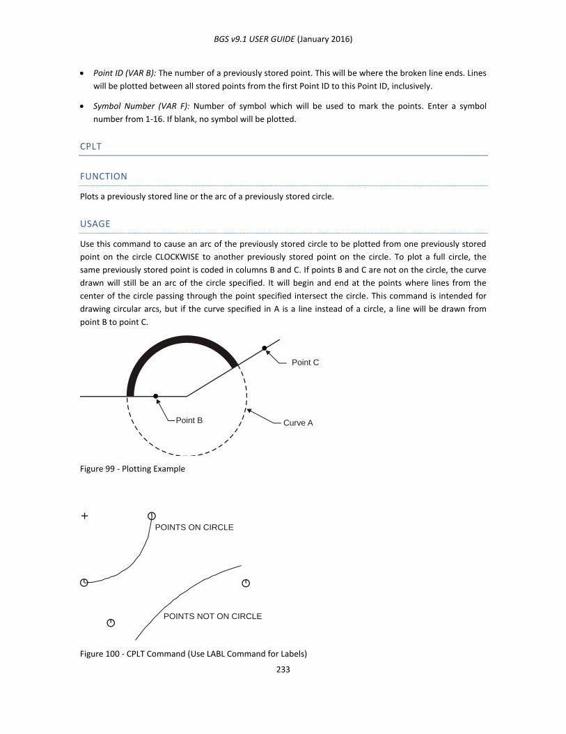
BGS v9.1 USER GUIDE (January 2016)
233
Point ID (VAR B): The number of a previously stored point. This will be where the broken line ends. Lines
will be plotted between all stored points from the first Point ID to this Point ID, inclusively.
Symbol Number (VAR F): Number of symbol which will be used to mark the points. Enter a symbol
number from 1-16. If blank, no symbol will be plotted.
CPLT
FUNCTION
Plots a previously stored line or the arc of a previously stored circle.
USAGE
Use this command to cause an arc of the previously stored circle to be plotted from one previously stored
point on the circle CLOCKWISE to another previously stored point on the circle. To plot a full circle, the
same previously stored point is coded in columns B and C. If points B and C are not on the circle, the curve
drawn will still be an arc of the circle specified. It will begin and end at the points where lines from the
center of the circle passing through the point specified intersect the circle. This command is intended for
drawing circular arcs, but if the curve specified in A is a line instead of a circle, a line will be drawn from
point B to point C.
Figure 99 - Plotting Example
Figure 100 - CPLT Command (Use LABL Command for Labels)
Point B
Point C
Curve A
POINTS ON CIRCLE
POINTS NOT ON CIRCLE
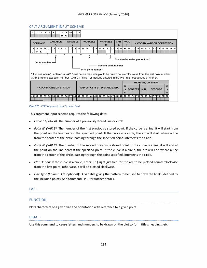
BGS v9.1 USER GUIDE (January 2016)
234
CPLT ARGUMENT INPUT SCHEME
Card 129 - CPLT Argument Input Scheme Card
This argument input scheme requires the following data:
Curve ID (VAR A): The number of a previously stored line or circle.
Point ID (VAR B): The number of the first previously stored point. If the curve is a line, it will start from
the point on the line nearest the specified point. If the curve is a circle, the arc will start where a line
from the center of the circle, passing through the specified point, intersects the circle.
Point ID (VAR C): The number of the second previously stored point. If the curve is a line, it will end at
the point on the line nearest the specified point. If the curve is a circle, the arc will end where a line
from the center of the circle, passing through the point specified, intersects the circle.
Plot Option: If the curve is a circle, enter (–1) right justified for the arc to be plotted counterclockwise
from the first point; otherwise, it will be plotted clockwise.
Line Type (Column 33) (optional): A variable giving the pattern to be used to draw the line(s) defined by
the included points. See command LPLT for further details.
LABL
FUNCTION
Plots characters of a given size and orientation with reference to a given point.
USAGE
Use this command to cause letters and numbers to be drawn on the plot to form titles, headings, etc.
1 2 3 4 5 6 7 8 9 10 11 12
R G
13 14 15 16 17 18 19 20 21 22 23 24 25 26 27 28 29 30 31 32 33 34 35 36 37 38 39 40 41 42 43 44 45 46 47
C P L T
Counterclockwise plot option *
Curve number
Second point number
N
or
S
E
or
W
48 49 50 51 52 53 54 55 56 57 58 59 60 61 62 63 64 65 66 67 68 69 70 71 72 73 74 75 76 77 78 79 80
VAR.
FX COORDINATE OR CORRECTIONCOMMAND
VARIABLE
A
VARIABLE
B
VARIABLE
C
VARIABLE
D
VAR.
E
First point number
* A minus one (-1) entered in VAR D will cause the circle plot to be drawn counterclockwise from the first point number
(VAR B) to the last point number (VAR C). This (-1) must be entered in the two rightmost spaces of VAR D.
Y COORDINATE OR STATION RADIUS, OFFSET, DISTANCE, ETC.DEGREES
BEAR, AZ, OR SKEW
MIN. SECONDS
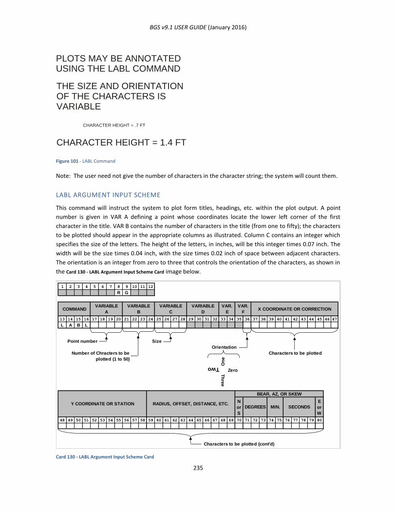
BGS v9.1 USER GUIDE (January 2016)
235
Figure 101 - LABL Command
Note: The user need not give the number of characters in the character string; the system will count them.
LABL ARGUMENT INPUT SCHEME
This command will instruct the system to plot form titles, headings, etc. within the plot output. A point
number is given in VAR A defining a point whose coordinates locate the lower left corner of the first
character in the title. VAR B contains the number of characters in the title (from one to fifty); the characters
to be plotted should appear in the appropriate columns as illustrated. Column C contains an integer which
specifies the size of the letters. The height of the letters, in inches, will be this integer times 0.07 inch. The
width will be the size times 0.04 inch, with the size times 0.02 inch of space between adjacent characters.
The orientation is an integer from zero to three that controls the orientation of the characters, as shown in
the Card 130 - LABL Argument Input Scheme Card image below.
Card 130 - LABL Argument Input Scheme Card
1 2 3 4 5 6 7 8 9 10 11 12
R G
13 14 15 16 17 18 19 20 21 22 23 24 25 26 27 28 29 30 31 32 33 34 35 36 37 38 39 40 41 42 43 44 45 46 47
L A B L
Point number Size
Orientation
Characters to be plotted
On
e
Zero
Th
ree
N
or
S
E
or
W
48 49 50 51 52 53 54 55 56 57 58 59 60 61 62 63 64 65 66 67 68 69 70 71 72 73 74 75 76 77 78 79 80
Characters to be plotted (cont'd)
Number of Chracters to be
plotted (1 to 50)
RADIUS, OFFSET, DISTANCE, ETC.Y COORDINATE OR STATIONSECONDSMIN.DEGREES
BEAR, AZ, OR SKEW
COMMANDVARIABLE
A
VARIABLE
B
VARIABLE
C
VARIABLE
D
VAR.
E
VAR.
FX COORDINATE OR CORRECTION
Two
PLOTS MAY BE ANNOTATED
USING THE LABL COMMAND
THE SIZE AND ORIENTATION
OF THE CHARACTERS IS
VARIABLE
CHARACTER HEIGHT = 1.4 FT
CHARACTER HEIGHT = .7 FT
BGS v9.1 USER GUIDE (January 2016)
236
This argument input scheme requires the following data:
Point ID (VAR. A): The number of a previously stored point which locates the lower left corner of the first
character.
Number of Characters (VAR. B): An integer defining the number of characters to be plotted (1 to 50)
Size (VAR. C): An integer defining the size of the characters: character height is this number times 0. 7
feet or 0.26 meters.
Orientation (VAR. F): The orientation of the label may be specified in any one of three ways. First, the
label is oriented with respect to the screen if an integer from zero to three is entered, right justified. If
“0” is entered, the bearing of the label is the positive Y-axis of the screen; if “1”, the bearing is the
negative X-axis; if “2”, the negative Y-axis, and if “3”, the positive X-axis. Second, the label is oriented
with respect to the four cardinal points of the compass, if an integer from four to seven is entered, right
justified. If “4” is entered, the bearing of the label is due north; if “5”, the bearing is due west; if “6”, due
south; if “7”, due east. Third, the desired bearing in degrees of the character string may be given,
entered right justified in columns 34 – 36. (This bearing must be 10 degrees or more, so the system does
not confuse it with the other ways of orienting the characters.) This bearing will be measured with
respect to the screen, not with respect to the user coordinates.
Characters: The characters to be plotted (maximum 44).
TICK
FUNCTION
Plots grid ticks at a given spacing over the body of a plot.
USAGE
Use this command to plot grid ticks (with North orientation) at a given spacing over the body of a plot. Ticks
are located on lines evenly divisible by the spacing. Note: the TICK command should be the last plot
command for a given plot axis, since the limits of the grid are determined from the previous plot commands
for the axis.
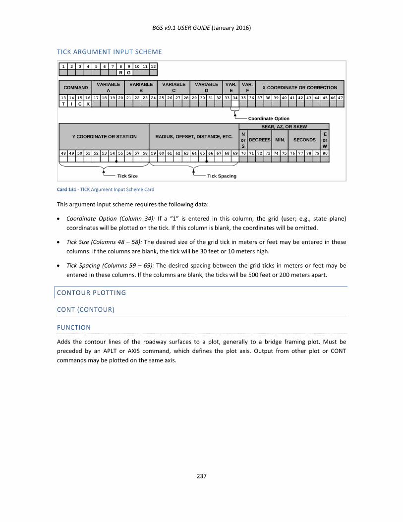
BGS v9.1 USER GUIDE (January 2016)
237
TICK ARGUMENT INPUT SCHEME
Card 131 - TICK Argument Input Scheme Card
This argument input scheme requires the following data:
Coordinate Option (Column 34): If a “1” is entered in this column, the grid (user; e.g., state plane)
coordinates will be plotted on the tick. If this column is blank, the coordinates will be omitted.
Tick Size (Columns 48 – 58): The desired size of the grid tick in meters or feet may be entered in these
columns. If the columns are blank, the tick will be 30 feet or 10 meters high.
Tick Spacing (Columns 59 – 69): The desired spacing between the grid ticks in meters or feet may be
entered in these columns. If the columns are blank, the ticks will be 500 feet or 200 meters apart.
CONTOUR PLOTTING
CONT (CONTOUR)
FUNCTION
Adds the contour lines of the roadway surfaces to a plot, generally to a bridge framing plot. Must be
preceded by an APLT or AXIS command, which defines the plot axis. Output from other plot or CONT
commands may be plotted on the same axis.
1 2 3 4 5 6 7 8 9 10 11 12
R G
13 14 15 16 17 18 19 20 21 22 23 24 25 26 27 28 29 30 31 32 33 34 35 36 37 38 39 40 41 42 43 44 45 46 47
T I C K
Coordinate Option
N
or
S
E
or
W
48 49 50 51 52 53 54 55 56 57 58 59 60 61 62 63 64 65 66 67 68 69 70 71 72 73 74 75 76 77 78 79 80
Tick Size Tick Spacing
COMMANDVARIABLE
A
VARIABLE
B
VARIABLE
C
VARIABLE
D
VAR.
E
VAR.
FX COORDINATE OR CORRECTION
RADIUS, OFFSET, DISTANCE, ETC.Y COORDINATE OR STATIONSECONDSMIN.DEGREES
BEAR, AZ, OR SKEW

BGS v9.1 USER GUIDE (January 2016)
238
Figure 102 - Example Contour Plot
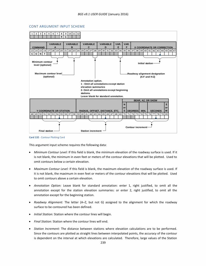
BGS v9.1 USER GUIDE (January 2016)
239
CONT ARGUMENT INPUT SCHEME
Card 132 - Contour Plotting Card
This argument input scheme requires the following data:
Minimum Contour Level: If this field is blank, the minimum elevation of the roadway surface is used. If it
is not blank, the minimum in even feet or meters of the contour elevations that will be plotted. Used to
omit contours below a certain elevation.
Maximum Contour Level: If this field is blank, the maximum elevation of the roadway surface is used. If
it is not blank, the maximum in even feet or meters of the contour elevations that will be plotted. Used
to omit contours above a certain elevation.
Annotation Option: Leave blank for standard annotation: enter 1, right justified, to omit all the
annotation except for the station elevation summaries: or enter 2, right justified, to omit all the
annotation except for the beginning station.
Roadway Alignment: The letter (A–Z, but not G) assigned to the alignment for which the roadway
surface to be contoured has been defined.
Initial Station: Station where the contour lines will begin.
Final Station: Station where the contour lines will end.
Station Increment: The distance between stations where elevation calculations are to be performed.
Since the contours are plotted as straight lines between interpolated points, the accuracy of the contour
is dependent on the interval at which elevations are calculated. Therefore, large values of the Station
1 2 3 4 5 6 7 8 9 10 11 12
R G
COMMAND
VARIABLE
A
VARIABLE
B
VARIABLE
C
VARIABLE
D
VAR.
E
VAR.
F X COORDINATE OR CORRECTION
13 14 15 16 17 18 19 20 21 22 23 24 25 26 27 28 29 30 31 32 33 34 35 36 37 38 39 40 41 42 43 44 45 46 47
C O N T
Minimum contour
level (optional)Initial station
Roadway alignment designation
(A-F and H-Z)
BEAR, AZ, OR SKEW
Y COORDINATE OR STATION RADIUS, OFFSET, DISTANCE, ETC.
N
or
S DEGREES MIN. SECONDS
E
or
W
48 49 50 51 52 53 54 55 56 57 58 59 60 61 62 63 64 65 66 67 68 69 70 71 72 73 74 75 76 77 78 79 80
Contour increment
Final station Station increment
Maximum contour level
(optional)
Annotation option.
1 - Omit all annotations except station
elevation summaries
2- Omit all annotations except beginning
stations.
Leave blank for standard annotation.

BGS v9.1 USER GUIDE (January 2016)
240
Increment should not be used except in regions where the contour lines are essentially straight lines. A
value of 10 feet or 5 meters is generally satisfactory, although smaller values may be needed in
extremely warped regions.
Contour Increment: The vertical distance between contour lines.
ALIGNMENT RELATIONSHIP
This section is under construction.
AREL - COMPUTE ALIGNMENT RELATIONSHIP
This section is under construction.
CREATING (PUNCHING) AND LISTING STORED GEOMETRY DATA
This section is under construction.
PLST - CREATE (PUNCH)/LIST STORED POINTS
This section is under construction.
CLST - CREATE (PUNCH)/LIST STORED CURVES
This section is under construction.
BGPN - TRANSFORM COMMAND UNITS AND PUNCH
This section is under construction.
BGS v9.1 USER GUIDE (January 2016)
241
CHAPTER 9: RUNNING BGS TO PROCESS THE INPUT FILE
This chapter is under construction.
STARTING THE BGS PROGRAM
This section is under construction.
DRAG-N-DROP METHOD
This section is under construction.
COMMAND LINE METHOD
This section is under construction.
RUNNING THE PROGRAM
This section is under construction.
BGS LOG FILE
This section is under construction.
PLOT PROCESSING
This section is under construction.
BGS COMMAND-LINE PARAMETERS
This section is under construction.
BGS v9.1 USER GUIDE (January 2016)
242
CHAPTER 10: BGS OUTPUT
This is a place holder for the indicated chapter to be considered for a future edition of this user guide.
SUMMARY OF OUTPUT FILES
This is a place holder for the indicated section to be considered for a future edition of this user guide.
LOG FILE (BGS.LOG)
This is a place holder for the indicated section to be considered for a future edition of this user guide.
REPORT FILES (<FILENAME>.LS1, .LS2, .LS3, .LS4, .LS5)
This is a place holder for the indicated section to be considered for a future edition of this user guide.
DGN PLOT FILE (<FILENAME>.DGN)
This is a place holder for the indicated section to be considered for a future edition of this user guide.
PUNCH FILE (<FILENAME>.PCH)
This is a place holder for the indicated section to be considered for a future edition of this user guide.
PUNCHING PREVIOUSLY STORED GEOMETRY DATA
This is a place holder for the indicated section to be considered for a future edition of this user guide.
PUNCHING PREVIOUSLY STORED DESIGN DATA
This is a place holder for the indicated section to be considered for a future edition of this user guide.
PUNCH FILE EXAMPLE
This is a place holder for the indicated section to be considered for a future edition of this user guide.
PROJECT WORK FILES
This is a place holder for the indicated section to be considered for a future edition of this user guide.
PAGE FILE (<FILENAME>.PAG)
This is a place holder for the indicated section to be considered for a future edition of this user guide.
BRIDGE FILE (<FILENAME>.BRI)
This is a place holder for the indicated section to be considered for a future edition of this user guide.

BGS v9.1 USER GUIDE (January 2016)
243
CHAPTER 11: USING BGS PROJECT WORK FILES
This chapter is under construction.
INTRODUCTION
This section is under construction.
PROJECT WORK FILES
This section is under construction.
PAGE FILE
This section is under construction.
BRIDGE FILE
This section is under construction.
CREATING PROJECT WORK FILES
This section is under construction.
USING EXISTING PROJECT WORK FILES
This section is under construction.
USING EXISTING WORK FILES (WITHOUT UPDATING THE FILES)
This section is under construction.
USING EXISTING WORK FILES (AND UPDATING THE FILES)
This section is under construction.

BGS v9.1 USER GUIDE (January 2016)
244
CHAPTER 12: EXAMPLE BRIDGE PROJECTS
This is a place holder for the indicated chapter to be considered for a future edition of this user guide.
SMALL BRIDGE PROJECT
This is a place holder for the indicated section to be considered for a future edition of this user guide.
LARGE BRIDGE PROJECT
This is a place holder for the indicated section to be considered for a future edition of this user guide.

BGS v9.1 USER GUIDE (January 2016)
245
APPENDIX A: BGS INPUT FORMS
This is a place holder for the indicated Appendix to be considered for a future edition of this user guide.

BGS v9.1 USER GUIDE (January 2016)
246
APPENDIX B: EXAMPLE BGS LOG FILE
The BGS log file captures the information that is splashed to the console screen during execution. When
something goes wrong, this file will contain helpful hints about the problem encountered during execution.
It is a high level view of the process of execution of the BGS run. The name of the log file is conjured to be
of this form <inputfilename>.lgc.
EXAMPLE 1 LGC (LOG OF C PROGRAM EXECUTION) OUTPUT FILE
##############################################################################
BEGIN bgs log ...
START bgs APPLICATION Date~time=2015-10-08~07:37:57 ...
Program Version Information:
..Version query results:
Texas Department of Transportation (TxDOT)
TxDOT Bridge Geometry System (bgs)
Components:
User Interface (bgs.exe), Version 9.1.5
Main Program (bgs1.exe), Version 9.1.5
The BGS log begins by indicating the date and time of the BGS run along with the version number of the two
program components, bgs.exe and bgs1.exe. The bgs.exe program component provides a user interface,
including various prompts, a display of the log data on the program console, calls the bgs1.exe program
component, then, if plotting is warranted after bgs1.exe completion, calls MicroStation for plotting. The
bgs1.exe program component performs file reading, all alignment and bridge geometry calculations, if
plotting is warranted, creates the MicroStation plot-instruction file, and otherwise handles output files.
NOTE: The paths in the log listings below have been shorted and the deleted portions represented by an
ellipse, thus “...” System Record Check:
..Input Data File = C:\Users\TBRADBER\...\Ex1_v9.1.5\Ex1h.dat
..Validating input fields:
Unit Field: Value < > is OK.
Job Type Field: Value <NEW> is OK.
Save Results Field: Value < NO> is OK.
Omit Stored Geometry Data Field: Value <YES> is OK.
Omit Stored Design Data Field: Value <YES> is OK.
Omit Stored Bridge Data Field: Value <YES> is OK.
Print Input Data Field: Value <YES> is OK.
Primary Processing Parameters:
..Input Data File = C:\Users\TBRADBER\...\Ex1_v9.1.5\Ex1h.dat
..Project Work Files will not be used.
..Results will not be saved.
Delete Existing Output Files (.ls and .pch files from previous run):
..No '.ls' files exist, thus no deletions were performed.
..No '.pch' file exists, thus a deletion was not performed.
START Primary Processing ...
END Primary Processing.
Primary Processing Results:
..The following output files have been created:
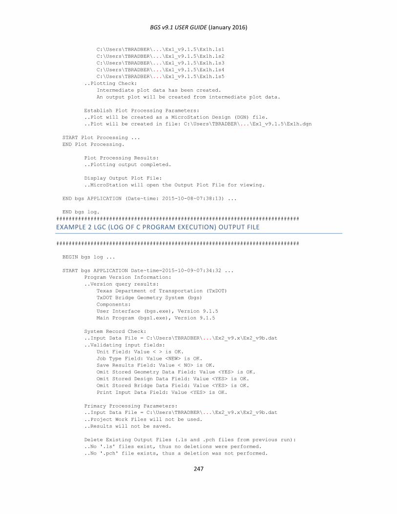
BGS v9.1 USER GUIDE (January 2016)
247
C:\Users\TBRADBER\...\Ex1_v9.1.5\Ex1h.ls1
C:\Users\TBRADBER\...\Ex1_v9.1.5\Ex1h.ls2
C:\Users\TBRADBER\...\Ex1_v9.1.5\Ex1h.ls3
C:\Users\TBRADBER\...\Ex1_v9.1.5\Ex1h.ls4
C:\Users\TBRADBER\...\Ex1_v9.1.5\Ex1h.ls5
..Plotting Check:
Intermediate plot data has been created.
An output plot will be created from intermediate plot data.
Establish Plot Processing Parameters:
..Plot will be created as a MicroStation Design (DGN) file.
..Plot will be created in file: C:\Users\TBRADBER\...\Ex1_v9.1.5\Ex1h.dgn
START Plot Processing ...
END Plot Processing.
Plot Processing Results:
..Plotting output completed.
Display Output Plot File:
..MicroStation will open the Output Plot File for viewing.
END bgs APPLICATION (Date~time: 2015-10-08~07:38:13) ...
END bgs log.
##############################################################################
EXAMPLE 2 LGC (LOG OF C PROGRAM EXECUTION) OUTPUT FILE
##############################################################################
BEGIN bgs log ...
START bgs APPLICATION Date~time=2015-10-09~07:34:32 ...
Program Version Information:
..Version query results:
Texas Department of Transportation (TxDOT)
TxDOT Bridge Geometry System (bgs)
Components:
User Interface (bgs.exe), Version 9.1.5
Main Program (bgs1.exe), Version 9.1.5
System Record Check:
..Input Data File = C:\Users\TBRADBER\...\Ex2_v9.x\Ex2_v9b.dat
..Validating input fields:
Unit Field: Value < > is OK.
Job Type Field: Value <NEW> is OK.
Save Results Field: Value < NO> is OK.
Omit Stored Geometry Data Field: Value <YES> is OK.
Omit Stored Design Data Field: Value <YES> is OK.
Omit Stored Bridge Data Field: Value <YES> is OK.
Print Input Data Field: Value <YES> is OK.
Primary Processing Parameters:
..Input Data File = C:\Users\TBRADBER\...\Ex2_v9.x\Ex2_v9b.dat
..Project Work Files will not be used.
..Results will not be saved.
Delete Existing Output Files (.ls and .pch files from previous run):
..No '.ls' files exist, thus no deletions were performed.
..No '.pch' file exists, thus a deletion was not performed.
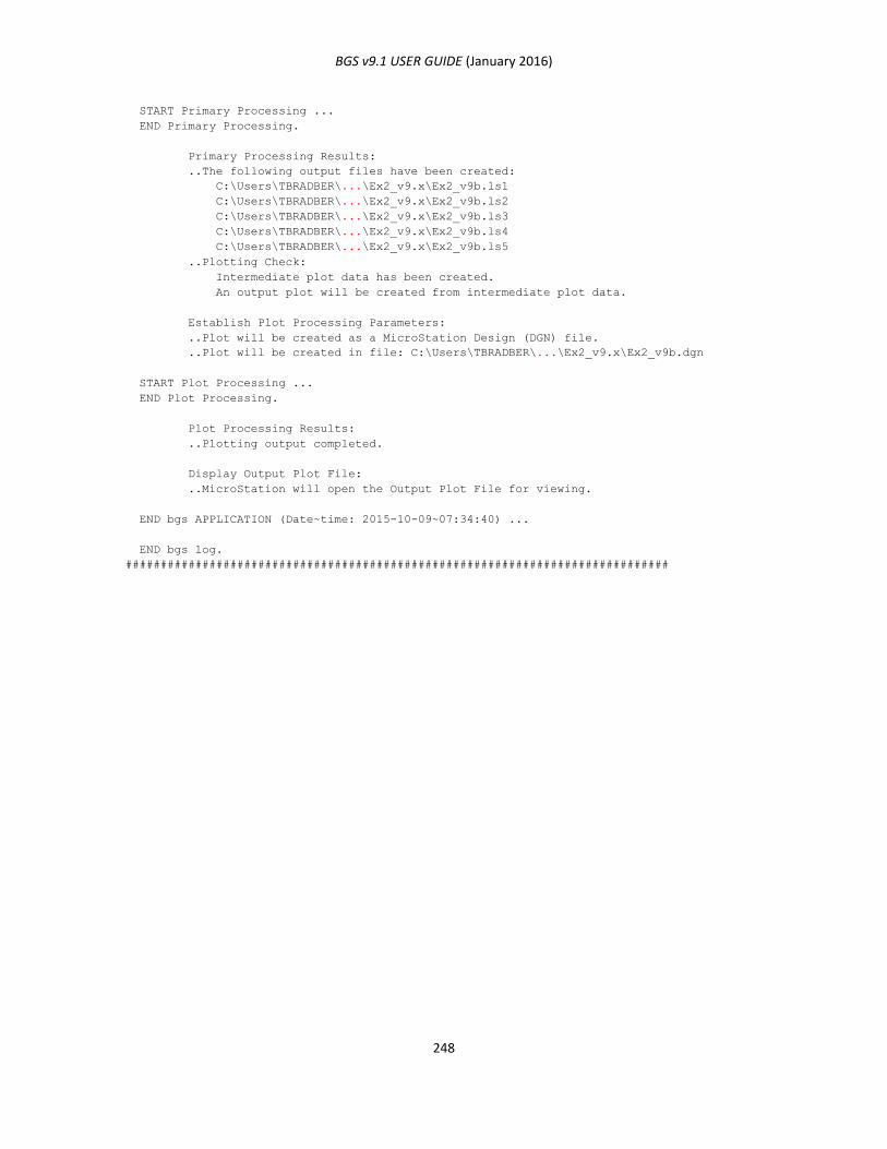
BGS v9.1 USER GUIDE (January 2016)
248
START Primary Processing ...
END Primary Processing.
Primary Processing Results:
..The following output files have been created:
C:\Users\TBRADBER\...\Ex2_v9.x\Ex2_v9b.ls1
C:\Users\TBRADBER\...\Ex2_v9.x\Ex2_v9b.ls2
C:\Users\TBRADBER\...\Ex2_v9.x\Ex2_v9b.ls3
C:\Users\TBRADBER\...\Ex2_v9.x\Ex2_v9b.ls4
C:\Users\TBRADBER\...\Ex2_v9.x\Ex2_v9b.ls5
..Plotting Check:
Intermediate plot data has been created.
An output plot will be created from intermediate plot data.
Establish Plot Processing Parameters:
..Plot will be created as a MicroStation Design (DGN) file.
..Plot will be created in file: C:\Users\TBRADBER\...\Ex2_v9.x\Ex2_v9b.dgn
START Plot Processing ...
END Plot Processing.
Plot Processing Results:
..Plotting output completed.
Display Output Plot File:
..MicroStation will open the Output Plot File for viewing.
END bgs APPLICATION (Date~time: 2015-10-09~07:34:40) ...
END bgs log.
##############################################################################
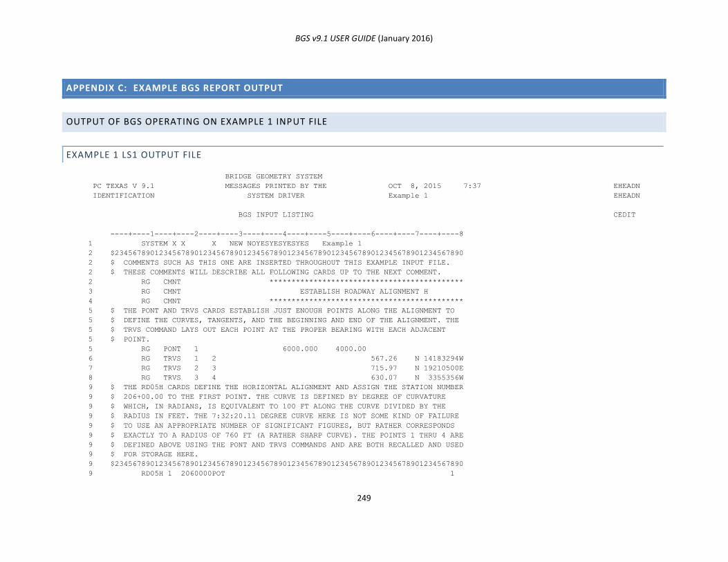
BGS v9.1 USER GUIDE (January 2016)
249
APPENDIX C: EXAMPLE BGS REPORT OUTPUT
OUTPUT OF BGS OPERATING ON EXAMPLE 1 INPUT FILE
EXAMPLE 1 LS1 OUTPUT FILE
BRIDGE GEOMETRY SYSTEM
PC TEXAS V 9.1 MESSAGES PRINTED BY THE OCT 8, 2015 7:37 EHEADN
IDENTIFICATION SYSTEM DRIVER Example 1 EHEADN
BGS INPUT LISTING CEDIT
----+----1----+----2----+----3----+----4----+----5----+----6----+----7----+----8
1 SYSTEM X X X NEW NOYESYESYESYES Example 1
2 $2345678901234567890123456789012345678901234567890123456789012345678901234567890
2 $ COMMENTS SUCH AS THIS ONE ARE INSERTED THROUGHOUT THIS EXAMPLE INPUT FILE.
2 $ THESE COMMENTS WILL DESCRIBE ALL FOLLOWING CARDS UP TO THE NEXT COMMENT.
2 RG CMNT ********************************************
3 RG CMNT ESTABLISH ROADWAY ALIGNMENT H
4 RG CMNT ********************************************
5 $ THE PONT AND TRVS CARDS ESTABLISH JUST ENOUGH POINTS ALONG THE ALIGNMENT TO
5 $ DEFINE THE CURVES, TANGENTS, AND THE BEGINNING AND END OF THE ALIGNMENT. THE
5 $ TRVS COMMAND LAYS OUT EACH POINT AT THE PROPER BEARING WITH EACH ADJACENT
5 $ POINT.
5 RG PONT 1 6000.000 4000.00
6 RG TRVS 1 2 567.26 N 14183294W
7 RG TRVS 2 3 715.97 N 19210500E
8 RG TRVS 3 4 630.07 N 3355356W
9 $ THE RD05H CARDS DEFINE THE HORIZONTAL ALIGNMENT AND ASSIGN THE STATION NUMBER
9 $ 206+00.00 TO THE FIRST POINT. THE CURVE IS DEFINED BY DEGREE OF CURVATURE
9 $ WHICH, IN RADIANS, IS EQUIVALENT TO 100 FT ALONG THE CURVE DIVIDED BY THE
9 $ RADIUS IN FEET. THE 7:32:20.11 DEGREE CURVE HERE IS NOT SOME KIND OF FAILURE
9 $ TO USE AN APPROPRIATE NUMBER OF SIGNIFICANT FIGURES, BUT RATHER CORRESPONDS
9 $ EXACTLY TO A RADIUS OF 760 FT (A RATHER SHARP CURVE). THE POINTS 1 THRU 4 ARE
9 $ DEFINED ABOVE USING THE PONT AND TRVS COMMANDS AND ARE BOTH RECALLED AND USED
9 $ FOR STORAGE HERE.
9 $2345678901234567890123456789012345678901234567890123456789012345678901234567890
9 RD05H 1 2060000POT 1
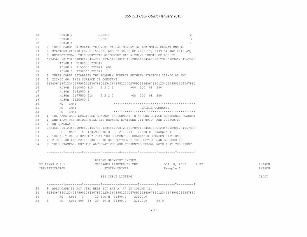
BGS v9.1 USER GUIDE (January 2016)
250
10 RD05H 2 7322011 2
11 RD05H 3 7322011 3
12 RD05H 4 4
13 $ THESE CARDS CALCULATE THE VERTICAL ALIGNMENT BY ASSIGNING ELEVATIONS TO
13 $ STATIONS 210+00.00, 21+55.00, AND 22+30.00 OF 2703.17, 2739.94 AND 2713.49,
13 $ RESPECTIVELY. THIS VERTICAL ALIGNMENT HAS A CURVE LENGTH OF 600 FT
13 $2345678901234567890123456789012345678901234567890123456789012345678901234567890
13 RD10H 1 2100000 270317
14 RD10H 2 2155000 272994 600
15 RD10H 3 2230000 271349
16 $ THESE CARDS ESTABLISH THE ROADWAY SURFACE BETWEEN STATIONS 211+00.00 AND
16 $ 222+00.00. THIS SURFACE IS CONSTANT.
16 $2345678901234567890123456789012345678901234567890123456789012345678901234567890
16 RD30H 2110000 11F 2 2 2 2 -08 200 08 200
17 RD30H 2132500 1
18 RD30H 2177500 21F 2 2 2 2 -08 200 08 200
19 RD30H 2220000 2
20 RG CMNT ********************************************
21 RG CMNT BRIDGE COMMANDS
22 RG CMNT ********************************************
23 $ THE NAME CARD SPECIFIES ROADWAY (ALIGNMENT) H AS THE BRIDGE REFERENCE ROADWAY
23 $ AND THAT THE BRIDGE WILL LIE BETWEEN STATIONS 211+00.00 AND 222+00.00
23 $ ON ROADWAY H
23 $2345678901234567890123456789012345678901234567890123456789012345678901234567890
23 RG NAME 5 13HL93BRIG H 21100.0 22200.0 Example 1
24 $ THE APLT CARDS SPECIFY THAT THE SEGMENT OF ROADWAY H BETWEEN STATIONS
24 $ 213+00.00 AND 221+00.00 IS TO BE PLOTTED. EITHER OPTION CAN BE USED IN
24 $ THIS EXAMPLE, BUT THE ALTERNATIVES ARE PRESENTED BELOW. NOTE THAT THE FIRST
----+----1----+----2----+----3----+----4----+----5----+----6----+----7----+----8
BRIDGE GEOMETRY SYSTEM
PC TEXAS V 9.1 MESSAGES PRINTED BY THE OCT 8, 2015 7:37 EHEADN
IDENTIFICATION SYSTEM DRIVER Example 1 EHEADN
BGS INPUT LISTING CEDIT
----+----1----+----2----+----3----+----4----+----5----+----6----+----7----+----8
24 $ APLT CARD IS NOT USED HERE (IT HAS A '$' IN COLUMN 1).
24 $2345678901234567890123456789012345678901234567890123456789012345678901234567890
24 RG APLT 1 20 100 H 21300.0 22100.0
25 $ RG APLT 500 33 20 10 H 21300.0 22100.0 20.0
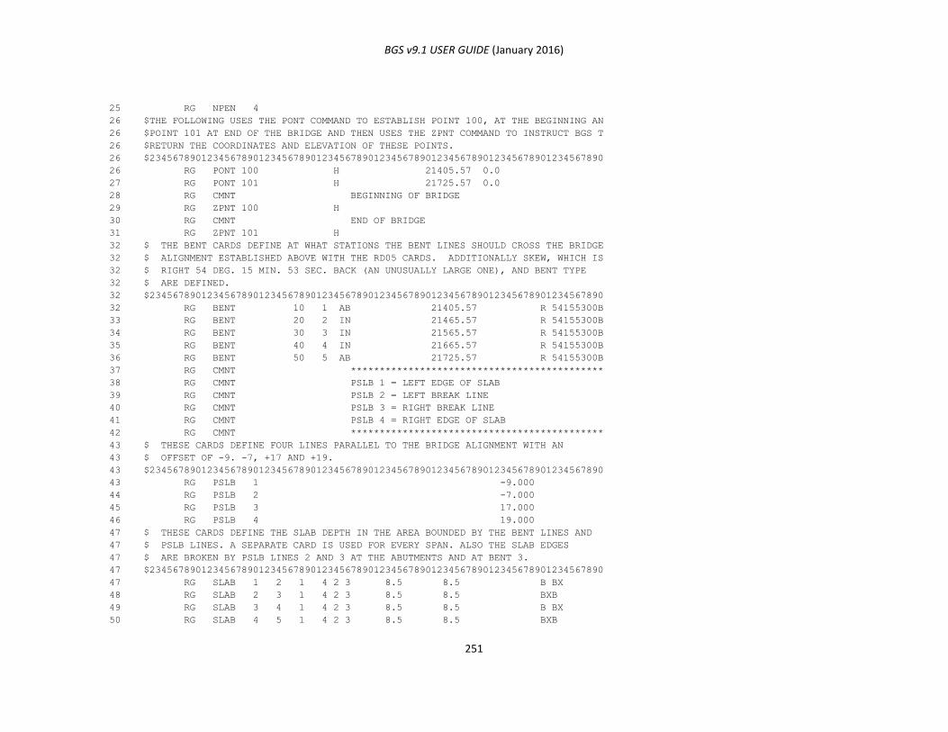
BGS v9.1 USER GUIDE (January 2016)
251
25 RG NPEN 4
26 $THE FOLLOWING USES THE PONT COMMAND TO ESTABLISH POINT 100, AT THE BEGINNING AN
26 $POINT 101 AT END OF THE BRIDGE AND THEN USES THE ZPNT COMMAND TO INSTRUCT BGS T
26 $RETURN THE COORDINATES AND ELEVATION OF THESE POINTS.
26 $2345678901234567890123456789012345678901234567890123456789012345678901234567890
26 RG PONT 100 H 21405.57 0.0
27 RG PONT 101 H 21725.57 0.0
28 RG CMNT BEGINNING OF BRIDGE
29 RG ZPNT 100 H
30 RG CMNT END OF BRIDGE
31 RG ZPNT 101 H
32 $ THE BENT CARDS DEFINE AT WHAT STATIONS THE BENT LINES SHOULD CROSS THE BRIDGE
32 $ ALIGNMENT ESTABLISHED ABOVE WITH THE RD05 CARDS. ADDITIONALLY SKEW, WHICH IS
32 $ RIGHT 54 DEG. 15 MIN. 53 SEC. BACK (AN UNUSUALLY LARGE ONE), AND BENT TYPE
32 $ ARE DEFINED.
32 $2345678901234567890123456789012345678901234567890123456789012345678901234567890
32 RG BENT 10 1 AB 21405.57 R 54155300B
33 RG BENT 20 2 IN 21465.57 R 54155300B
34 RG BENT 30 3 IN 21565.57 R 54155300B
35 RG BENT 40 4 IN 21665.57 R 54155300B
36 RG BENT 50 5 AB 21725.57 R 54155300B
37 RG CMNT ********************************************
38 RG CMNT PSLB 1 = LEFT EDGE OF SLAB
39 RG CMNT PSLB 2 = LEFT BREAK LINE
40 RG CMNT PSLB 3 = RIGHT BREAK LINE
41 RG CMNT PSLB 4 = RIGHT EDGE OF SLAB
42 RG CMNT ********************************************
43 $ THESE CARDS DEFINE FOUR LINES PARALLEL TO THE BRIDGE ALIGNMENT WITH AN
43 $ OFFSET OF -9. -7, +17 AND +19.
43 $2345678901234567890123456789012345678901234567890123456789012345678901234567890
43 RG PSLB 1 -9.000
44 RG PSLB 2 -7.000
45 RG PSLB 3 17.000
46 RG PSLB 4 19.000
47 $ THESE CARDS DEFINE THE SLAB DEPTH IN THE AREA BOUNDED BY THE BENT LINES AND
47 $ PSLB LINES. A SEPARATE CARD IS USED FOR EVERY SPAN. ALSO THE SLAB EDGES
47 $ ARE BROKEN BY PSLB LINES 2 AND 3 AT THE ABUTMENTS AND AT BENT 3.
47 $2345678901234567890123456789012345678901234567890123456789012345678901234567890
47 RG SLAB 1 2 1 4 2 3 8.5 8.5 B BX
48 RG SLAB 2 3 1 4 2 3 8.5 8.5 BXB
49 RG SLAB 3 4 1 4 2 3 8.5 8.5 B BX
50 RG SLAB 4 5 1 4 2 3 8.5 8.5 BXB
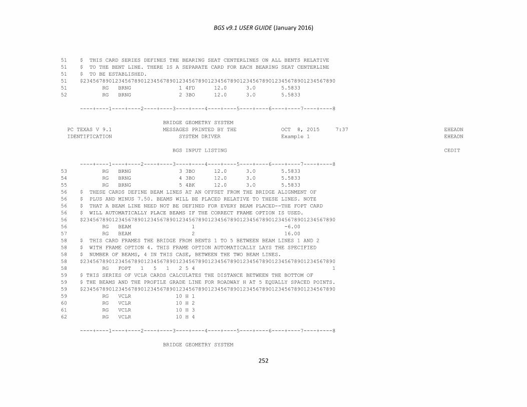
BGS v9.1 USER GUIDE (January 2016)
252
51 $ THIS CARD SERIES DEFINES THE BEARING SEAT CENTERLINES ON ALL BENTS RELATIVE
51 $ TO THE BENT LINE. THERE IS A SEPARATE CARD FOR EACH BEARING SEAT CENTERLINE
51 $ TO BE ESTABLISHED.
51 $2345678901234567890123456789012345678901234567890123456789012345678901234567890
51 RG BRNG 1 4FD 12.0 3.0 5.5833
52 RG BRNG 2 3BO 12.0 3.0 5.5833
----+----1----+----2----+----3----+----4----+----5----+----6----+----7----+----8
BRIDGE GEOMETRY SYSTEM
PC TEXAS V 9.1 MESSAGES PRINTED BY THE OCT 8, 2015 7:37 EHEADN
IDENTIFICATION SYSTEM DRIVER Example 1 EHEADN
BGS INPUT LISTING CEDIT
----+----1----+----2----+----3----+----4----+----5----+----6----+----7----+----8
53 RG BRNG 3 3BO 12.0 3.0 5.5833
54 RG BRNG 4 3BO 12.0 3.0 5.5833
55 RG BRNG 5 4BK 12.0 3.0 5.5833
56 $ THESE CARDS DEFINE BEAM LINES AT AN OFFSET FROM THE BRIDGE ALIGNMENT OF
56 $ PLUS AND MINUS 7.50. BEAMS WILL BE PLACED RELATIVE TO THESE LINES. NOTE
56 $ THAT A BEAM LINE NEED NOT BE DEFINED FOR EVERY BEAM PLACED--THE FOPT CARD
56 $ WILL AUTOMATICALLY PLACE BEAMS IF THE CORRECT FRAME OPTION IS USED.
56 $2345678901234567890123456789012345678901234567890123456789012345678901234567890
56 RG BEAM 1 -6.00
57 RG BEAM 2 16.00
58 $ THIS CARD FRAMES THE BRIDGE FROM BENTS 1 TO 5 BETWEEN BEAM LINES 1 AND 2
58 $ WITH FRAME OPTION 4. THIS FRAME OPTION AUTOMATICALLY LAYS THE SPECIFIED
58 $ NUMBER OF BEAMS, 4 IN THIS CASE, BETWEEN THE TWO BEAM LINES.
58 $2345678901234567890123456789012345678901234567890123456789012345678901234567890
58 RG FOPT 1 5 1 2 5 4 1
59 $ THIS SERIES OF VCLR CARDS CALCULATES THE DISTANCE BETWEEN THE BOTTOM OF
59 $ THE BEAMS AND THE PROFILE GRADE LINE FOR ROADWAY H AT 5 EQUALLY SPACED POINTS.
59 $2345678901234567890123456789012345678901234567890123456789012345678901234567890
59 RG VCLR 10 H 1
60 RG VCLR 10 H 2
61 RG VCLR 10 H 3
62 RG VCLR 10 H 4
----+----1----+----2----+----3----+----4----+----5----+----6----+----7----+----8
BRIDGE GEOMETRY SYSTEM
BGS v9.1 USER GUIDE (January 2016)
253
PC TEXAS V 9.1 MESSAGES PRINTED BY THE OCT 8, 2015 7:37 EHEADN
IDENTIFICATION GEOMETRY PROCESS Example 1 EHEADN
BRIDGE GEOMETRY SYSTEM
PC TEXAS V 9.1 MESSAGES PRINTED BY THE OCT 8, 2015 7:37 EHEADN
IDENTIFICATION DESIGN EDIT AND STORE PROCESS Example 1 EHEADN
BRIDGE GEOMETRY SYSTEM
PC TEXAS V 9.1 MESSAGES PRINTED BY THE OCT 8, 2015 7:37 EHEADN
IDENTIFICATION GEOMETRY PROCESS Example 1 EHEADN
NOW FITTING A LINE TO POINTS 1 THROUGH 7. ORIEN
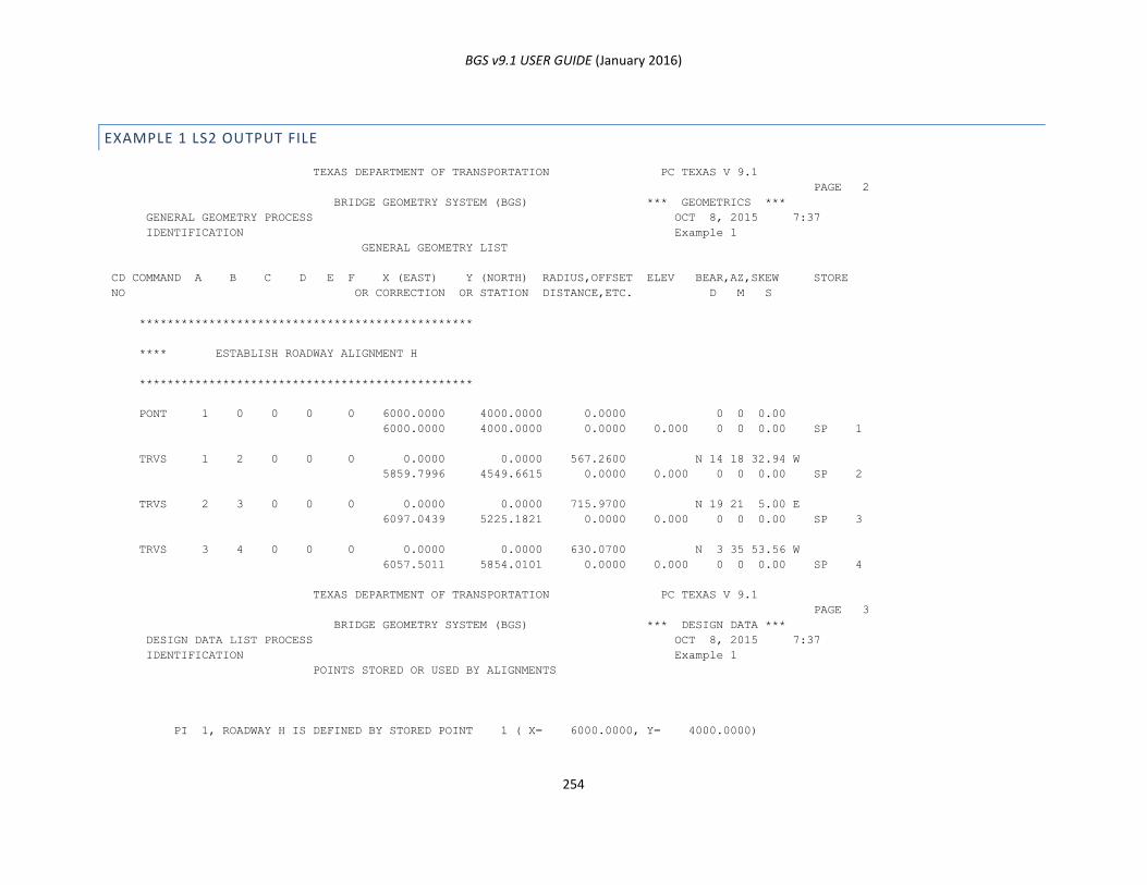
BGS v9.1 USER GUIDE (January 2016)
254
EXAMPLE 1 LS2 OUTPUT FILE
TEXAS DEPARTMENT OF TRANSPORTATION PC TEXAS V 9.1
PAGE 2
BRIDGE GEOMETRY SYSTEM (BGS) *** GEOMETRICS ***
GENERAL GEOMETRY PROCESS OCT 8, 2015 7:37
IDENTIFICATION Example 1
GENERAL GEOMETRY LIST
CD COMMAND A B C D E F X (EAST) Y (NORTH) RADIUS,OFFSET ELEV BEAR,AZ,SKEW STORE
NO OR CORRECTION OR STATION DISTANCE,ETC. D M S
************************************************
**** ESTABLISH ROADWAY ALIGNMENT H
************************************************
PONT 1 0 0 0 0 6000.0000 4000.0000 0.0000 0 0 0.00
6000.0000 4000.0000 0.0000 0.000 0 0 0.00 SP 1
TRVS 1 2 0 0 0 0.0000 0.0000 567.2600 N 14 18 32.94 W
5859.7996 4549.6615 0.0000 0.000 0 0 0.00 SP 2
TRVS 2 3 0 0 0 0.0000 0.0000 715.9700 N 19 21 5.00 E
6097.0439 5225.1821 0.0000 0.000 0 0 0.00 SP 3
TRVS 3 4 0 0 0 0.0000 0.0000 630.0700 N 3 35 53.56 W
6057.5011 5854.0101 0.0000 0.000 0 0 0.00 SP 4
TEXAS DEPARTMENT OF TRANSPORTATION PC TEXAS V 9.1
PAGE 3
BRIDGE GEOMETRY SYSTEM (BGS) *** DESIGN DATA ***
DESIGN DATA LIST PROCESS OCT 8, 2015 7:37
IDENTIFICATION Example 1
POINTS STORED OR USED BY ALIGNMENTS
PI 1, ROADWAY H IS DEFINED BY STORED POINT 1 ( X= 6000.0000, Y= 4000.0000)

BGS v9.1 USER GUIDE (January 2016)
255
PI 2, ROADWAY H IS DEFINED BY STORED POINT 2 ( X= 5859.7996, Y= 4549.6615)
PI 3, ROADWAY H IS DEFINED BY STORED POINT 3 ( X= 6097.0439, Y= 5225.1821)
PI 4, ROADWAY H IS DEFINED BY STORED POINT 4 ( X= 6057.5011, Y= 5854.0101)
TEXAS DEPARTMENT OF TRANSPORTATION PC TEXAS V 9.1
PAGE 4
BRIDGE GEOMETRY SYSTEM (BGS) *** DESIGN DATA ***
HORIZONTAL ALIGNMENT PROCESS OCT 8, 2015 7:37
IDENTIFICATION Example 1
HORIZONTAL ALIGNMENT LIST
FOR ROADWAY H
COMPUTATIONS BASED ON ARC DEFINITION
P.I. X Y
1 206+00.0000 6000.0000 4000.0000
N 14 18 32.94 W 567.2600 FT.
209+37.3643 PC 7 32 20.11 D 229.8957 T 5916.6191 4326.8980
2 211+67.2600 PI 33 39 37.94 RT 446.4902 L 5859.7996 4549.6615
213+83.8546 PT 759.9999 R 5935.9780 4766.5690
N 19 21 5.00 E 715.9700 FT.
217+15.6532 PC 7 32 20.11 D 154.2757 T 6045.9230 5079.6224
3 218+69.9289 PI 22 56 58.56 LT 304.4150 L 6097.0439 5225.1821
220+20.0682 PT 759.9999 R 6087.3617 5379.1537
N 3 35 53.56 W 630.0700 FT.
4 224+95.8626 6057.5011 5854.0101
TEXAS DEPARTMENT OF TRANSPORTATION PC TEXAS V 9.1
PAGE 5
BRIDGE GEOMETRY SYSTEM (BGS) *** DESIGN DATA ***
DESIGN DATA LIST PROCESS OCT 8, 2015 7:37
IDENTIFICATION Example 1
SORTED DESIGN DATA
CARD TYPE RD05 H O R I Z O N T A L A L I G N M E N T
R P.I. DEGREE RADIUS ROUND
O N BEG. SPIRAL

BGS v9.1 USER GUIDE (January 2016)
256
A U OF OR BRNG
D M STATION STA. LENGTHS P.I. COORDINATES
W B CURVE FORWARD OR
A E I.D.
Y R TANGENT HOLD
DEG MIN SEC IN OUT X Y
H 1 206+00.0000 POT 0 0 0.00 0.0000 0.0 0.0 6000.0000 4000.0000 0
H 2 211+67.2600 7 32 20.11 759.9999 0.0 0.0 5859.7996 4549.6615
H 3 218+69.9289 7 32 20.11 759.9999 0.0 0.0 6097.0439 5225.1821
H 4 224+95.8626 0 0 0.00 0.0000 0.0 0.0 6057.5011 5854.0101
TEXAS DEPARTMENT OF TRANSPORTATION PC TEXAS V 9.1
PAGE 6
BRIDGE GEOMETRY SYSTEM (BGS) *** DESIGN DATA ***
DESIGN DATA LIST PROCESS OCT 8, 2015 7:37
IDENTIFICATION Example 1
SORTED DESIGN DATA
CARD TYPE RD10 P R O F I L E G R A D E
R P.I. FIRST SECOND
O N VERTICAL
A U VERTICAL VERTICAL ELEVATION
D M P.I. P.I. EXTERNAL GRADE
W B CURVE CURVE CORRECTION
A E STATION ELEVATION
Y R LENGTH LENGTH
H 1 210+00.00 2703.17 0. 0. 0.00
H 2 215+50.00 2729.94 600. 0. 0.00 -5.2955 0.048673
H 3 223+00.00 2713.49 0. 0. 0.00 -0.021933
TEXAS DEPARTMENT OF TRANSPORTATION PC TEXAS V 9.1
PAGE 7
BRIDGE GEOMETRY SYSTEM (BGS) *** DESIGN DATA ***
DESIGN DATA LIST PROCESS OCT 8, 2015 7:37
IDENTIFICATION Example 1
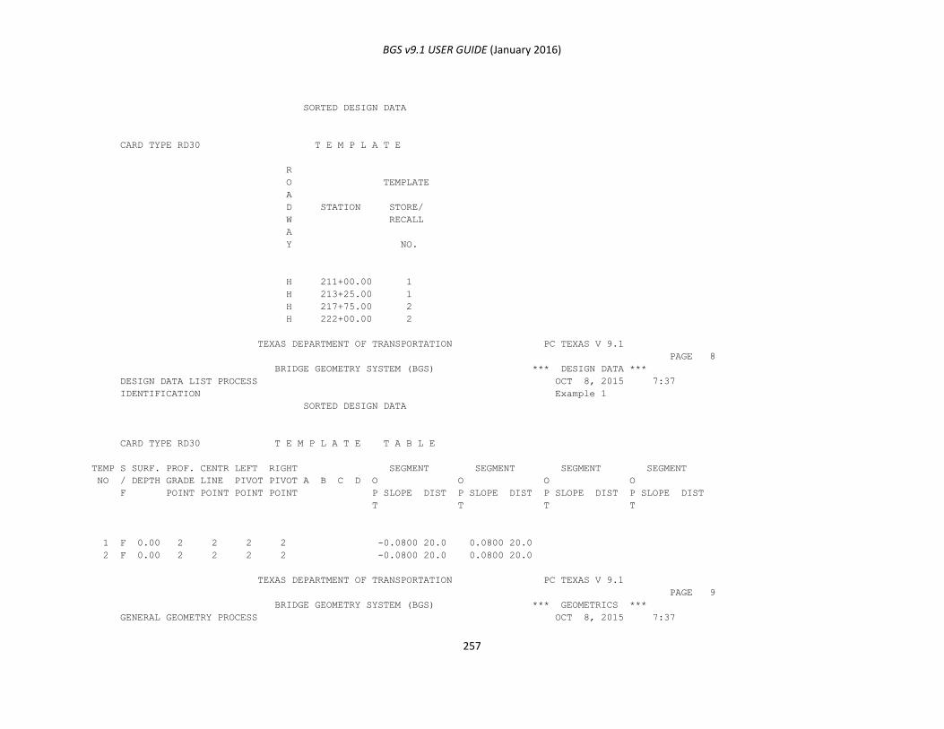
BGS v9.1 USER GUIDE (January 2016)
257
SORTED DESIGN DATA
CARD TYPE RD30 T E M P L A T E
R
O TEMPLATE
A
D STATION STORE/
W RECALL
A
Y NO.
H 211+00.00 1
H 213+25.00 1
H 217+75.00 2
H 222+00.00 2
TEXAS DEPARTMENT OF TRANSPORTATION PC TEXAS V 9.1
PAGE 8
BRIDGE GEOMETRY SYSTEM (BGS) *** DESIGN DATA ***
DESIGN DATA LIST PROCESS OCT 8, 2015 7:37
IDENTIFICATION Example 1
SORTED DESIGN DATA
CARD TYPE RD30 T E M P L A T E T A B L E
TEMP S SURF. PROF. CENTR LEFT RIGHT SEGMENT SEGMENT SEGMENT SEGMENT
NO / DEPTH GRADE LINE PIVOT PIVOT A B C D O O O O
F POINT POINT POINT POINT P SLOPE DIST P SLOPE DIST P SLOPE DIST P SLOPE DIST
T T T T
1 F 0.00 2 2 2 2 -0.0800 20.0 0.0800 20.0
2 F 0.00 2 2 2 2 -0.0800 20.0 0.0800 20.0
TEXAS DEPARTMENT OF TRANSPORTATION PC TEXAS V 9.1
PAGE 9
BRIDGE GEOMETRY SYSTEM (BGS) *** GEOMETRICS ***
GENERAL GEOMETRY PROCESS OCT 8, 2015 7:37

BGS v9.1 USER GUIDE (January 2016)
258
IDENTIFICATION Example 1
GENERAL GEOMETRY LIST
CD COMMAND A B C D E F X (EAST) Y (NORTH) RADIUS,OFFSET ELEV BEAR,AZ,SKEW STORE
NO OR CORRECTION OR STATION DISTANCE,ETC. D M S
************************************************
**** BRIDGE COMMANDS
************************************************
TEXAS DEPARTMENT OF TRANSPORTATION PC TEXAS V 9.1
PAGE 10
BRIDGE GEOMETRY SYSTEM (BGS) *** BRIDGE GEOMETRICS ***
Example 1 OCT 8, 2015 7:37
IDENTIFICATION Example 1
BRIDGE GEOMETRY LIST
CD COMMAND A B C D E F X(EAST) Y(NORTH) RADIUS,OFFSET ELEV. BEAR,AZ,SKEW STORE
NO OR CORRECTION OR STATION DISTANCE,ETC. D M S
NAME 5 13 HL93 BRIG H 0 21100.0000 22200.0000 Example 1 STR 1
APLT 1 20. 100. H 21300.0000 22100.0000
TEXAS DEPARTMENT OF TRANSPORTATION PC TEXAS V 9.1
PAGE 11
BRIDGE GEOMETRY SYSTEM (BGS) *** GEOMETRICS ***
ALIGNMENT PLOT PROCESS OCT 8, 2015 7:37
IDENTIFICATION Example 1
* * * ALIGNMENT PLOT DATA FOR ROADWAY H * * *
ALIGNMENT ELEMENT BEGINNING EAST (X) NORTH (Y) BEARING RADIUS,
ELEMENT TYPE STATION BEGINNING BEGINNING SPIRAL LENGTH,
NUMBER OR STA. BACK STA. FORWARD
1 ARC 213+00.00 5912.6085 4686.0810 N 13 1 46.78 E 760.00
2 LINE 213+83.85 5935.9780 4766.5690 N 19 21 5.00 E
3 ARC 217+15.65 6045.9230 5079.6224 N 19 21 5.00 E 760.00

BGS v9.1 USER GUIDE (January 2016)
259
4 LINE 220+20.06 6087.3617 5379.1537 N 3 35 53.56 W
5 END STA 221+00.00 6082.3452 5458.9279 N 3 35 53.56 W
* * * TABLE OF CENTERS FOR ALIGNMENT ELEMENTS AND OFFSETS * * *
ALIGNMENT OFFSET PARALLEL TO EAST (X) NORTH (Y)
ELEMENT LINE ALIGNMENT
NUMBER NUMBER ELEMENT NO.
1 6653.0410 4514.7349
3 5328.8600 5331.4566
* * * CURVE FIT DATA FOR ALL ALIGNMENT ELEMENTS AND OFFSETS * * *
POINT STATION EAST (X) NORTH (Y) --------- S O U R C E ---------
ALIGNMENT OFFSET INTERIOR
ELEMENT LINE POINT
1 213+00.00 5912.6085 4686.0810 1
2 213+41.92 5923.1829 4726.6474 1 *
3 213+83.85 5935.9780 4766.5690 2
4 217+15.65 6045.9230 5079.6224 3
5 218+67.86 6081.6897 5227.3063 3 *
6 220+20.06 6087.3617 5379.1537 4
7 221+00.00 6082.3452 5458.9279 5
TEXAS DEPARTMENT OF TRANSPORTATION PC TEXAS V 9.1

BGS v9.1 USER GUIDE (January 2016)
260
PAGE 12
BRIDGE GEOMETRY SYSTEM (BGS) *** GEOMETRICS ***
ALIGNMENT PLOT PROCESS OCT 8, 2015 7:37
IDENTIFICATION Example 1
* * * ALIGNMENT PLOT DATA FOR ROADWAY H * * *
THE PLOT SCALE IS 1.0 FEET PER FOOT.
TICK MARKS WILL BE DRAWN EVERY 20 FEET ALONG THE CENTERLINE.
STATION VALUES WILL BE LABELED EVERY 100 FEET ALONG THE CENTERLINE.
NOW FITTING A LINE TO POINTS 1 THROUGH 7. ORIEN
THIS PLOT WILL COVER A DISTANCE OF 791.03 FEET.
THE BEARING OF THE CURVE-FIT LINE IS N 13 46 49.28 E
THIS SEGMENT WILL START AT ALIGNMENT ELEMENT 1 AND CONTINUE UP TO ELEMENT 5.
REFERENCE COORDINATES ARE 1064.9298 X, 5875.0229 Y.
ORIGIN COORDINATES ARE 10777.0899 X, 3493.0180 Y.
NOW PLOTTING ELEMENTS 1 TO 5.
TEXAS DEPARTMENT OF TRANSPORTATION PC TEXAS V 9.1
PAGE 13
BRIDGE GEOMETRY SYSTEM (BGS) *** GEOMETRICS ***
GENERAL GEOMETRY PROCESS OCT 8, 2015 7:37
IDENTIFICATION Example 1
GENERAL GEOMETRY LIST
CD COMMAND A B C D E F X (EAST) Y (NORTH) RADIUS,OFFSET ELEV BEAR,AZ,SKEW STORE
NO OR CORRECTION OR STATION DISTANCE,ETC. D M S
NPEN 4 (RED)
PONT 100 0 0 0 H 0 0.0000 21405.5700 0.0000 0 0 0.00
5943.1736 4787.0576 0.0000 2721.486 0 0 0.00 SP 100
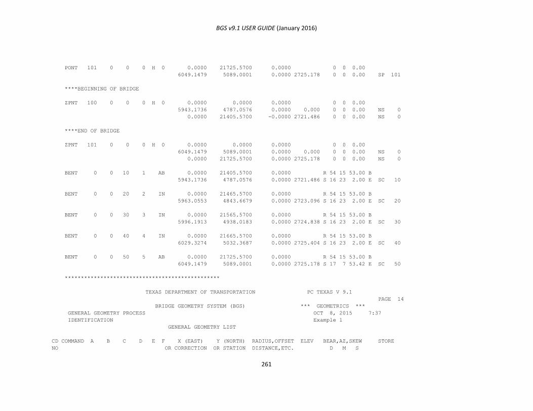
BGS v9.1 USER GUIDE (January 2016)
261
PONT 101 0 0 0 H 0 0.0000 21725.5700 0.0000 0 0 0.00
6049.1479 5089.0001 0.0000 2725.178 0 0 0.00 SP 101
****BEGINNING OF BRIDGE
ZPNT 100 0 0 0 H 0 0.0000 0.0000 0.0000 0 0 0.00
5943.1736 4787.0576 0.0000 0.000 0 0 0.00 NS 0
0.0000 21405.5700 -0.0000 2721.486 0 0 0.00 NS 0
****END OF BRIDGE
ZPNT 101 0 0 0 H 0 0.0000 0.0000 0.0000 0 0 0.00
6049.1479 5089.0001 0.0000 0.000 0 0 0.00 NS 0
0.0000 21725.5700 0.0000 2725.178 0 0 0.00 NS 0
BENT 0 0 10 1 AB 0.0000 21405.5700 0.0000 R 54 15 53.00 B
5943.1736 4787.0576 0.0000 2721.486 S 16 23 2.00 E SC 10
BENT 0 0 20 2 IN 0.0000 21465.5700 0.0000 R 54 15 53.00 B
5963.0553 4843.6679 0.0000 2723.096 S 16 23 2.00 E SC 20
BENT 0 0 30 3 IN 0.0000 21565.5700 0.0000 R 54 15 53.00 B
5996.1913 4938.0183 0.0000 2724.838 S 16 23 2.00 E SC 30
BENT 0 0 40 4 IN 0.0000 21665.5700 0.0000 R 54 15 53.00 B
6029.3274 5032.3687 0.0000 2725.404 S 16 23 2.00 E SC 40
BENT 0 0 50 5 AB 0.0000 21725.5700 0.0000 R 54 15 53.00 B
6049.1479 5089.0001 0.0000 2725.178 S 17 7 53.42 E SC 50
************************************************
TEXAS DEPARTMENT OF TRANSPORTATION PC TEXAS V 9.1
PAGE 14
BRIDGE GEOMETRY SYSTEM (BGS) *** GEOMETRICS ***
GENERAL GEOMETRY PROCESS OCT 8, 2015 7:37
IDENTIFICATION Example 1
GENERAL GEOMETRY LIST
CD COMMAND A B C D E F X (EAST) Y (NORTH) RADIUS,OFFSET ELEV BEAR,AZ,SKEW STORE
NO OR CORRECTION OR STATION DISTANCE,ETC. D M S
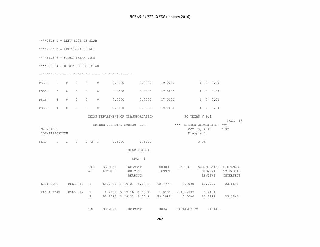
BGS v9.1 USER GUIDE (January 2016)
262
****PSLB 1 = LEFT EDGE OF SLAB
****PSLB 2 = LEFT BREAK LINE
****PSLB 3 = RIGHT BREAK LINE
****PSLB 4 = RIGHT EDGE OF SLAB
************************************************
PSLB 1 0 0 0 0 0.0000 0.0000 -9.0000 0 0 0.00
PSLB 2 0 0 0 0 0.0000 0.0000 -7.0000 0 0 0.00
PSLB 3 0 0 0 0 0.0000 0.0000 17.0000 0 0 0.00
PSLB 4 0 0 0 0 0.0000 0.0000 19.0000 0 0 0.00
TEXAS DEPARTMENT OF TRANSPORTATION PC TEXAS V 9.1
PAGE 15
BRIDGE GEOMETRY SYSTEM (BGS) *** BRIDGE GEOMETRICS ***
Example 1 OCT 8, 2015 7:37
IDENTIFICATION Example 1
SLAB 1 2 1 4 2 3 8.5000 8.5000 B BX
SLAB REPORT
SPAN 1
SEG. SEGMENT SEGMENT CHORD RADIUS ACCUMULATED DISTANCE
NO. LENGTH OR CHORD LENGTH SEGMENT TO RADIAL
BEARING LENGTHS INTERSECT
LEFT EDGE (PSLB 1) 1 62.7797 N 19 21 5.00 E 62.7797 0.0000 62.7797 23.8641
RIGHT EDGE (PSLB 4) 1 1.9101 N 19 16 39.15 E 1.9101 -740.9999 1.9101
2 55.3085 N 19 21 5.00 E 55.3085 0.0000 57.2186 33.3545
SEG. SEGMENT SEGMENT SKEW DISTANCE TO RADIAL
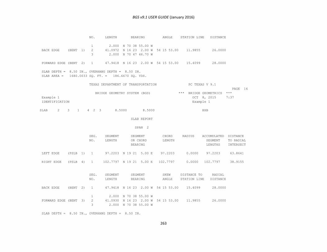
BGS v9.1 USER GUIDE (January 2016)
263
NO. LENGTH BEARING ANGLE STATION LINE DISTANCE
1 2.000 N 70 38 55.00 W
BACK EDGE (BENT 1) 2 41.0972 N 16 23 2.00 W 54 15 53.00 11.9855 26.0000
3 2.000 N 70 47 46.70 W
FORWARD EDGE (BENT 2) 1 47.9418 N 16 23 2.00 W 54 15 53.00 15.4099 28.0000
SLAB DEPTH = 8.50 IN., OVERHANG DEPTH = 8.50 IN.
SLAB AREA = 1680.0033 SQ. FT. = 186.6670 SQ. YDS.
TEXAS DEPARTMENT OF TRANSPORTATION PC TEXAS V 9.1
PAGE 16
BRIDGE GEOMETRY SYSTEM (BGS) *** BRIDGE GEOMETRICS ***
Example 1 OCT 8, 2015 7:37
IDENTIFICATION Example 1
SLAB 2 3 1 4 2 3 8.5000 8.5000 BXB
SLAB REPORT
SPAN 2
SEG. SEGMENT SEGMENT CHORD RADIUS ACCUMULATED DISTANCE
NO. LENGTH OR CHORD LENGTH SEGMENT TO RADIAL
BEARING LENGTHS INTERSECT
LEFT EDGE (PSLB 1) 1 97.2203 N 19 21 5.00 E 97.2203 0.0000 97.2203 63.8641
RIGHT EDGE (PSLB 4) 1 102.7797 N 19 21 5.00 E 102.7797 0.0000 102.7797 38.9155
SEG. SEGMENT SEGMENT SKEW DISTANCE TO RADIAL
NO. LENGTH BEARING ANGLE STATION LINE DISTANCE
BACK EDGE (BENT 2) 1 47.9418 N 16 23 2.00 W 54 15 53.00 15.4099 28.0000
1 2.000 N 70 38 55.00 W
FORWARD EDGE (BENT 3) 2 41.0930 N 16 23 2.00 W 54 15 53.00 11.9855 26.0000
3 2.000 N 70 38 55.00 W
SLAB DEPTH = 8.50 IN., OVERHANG DEPTH = 8.50 IN.
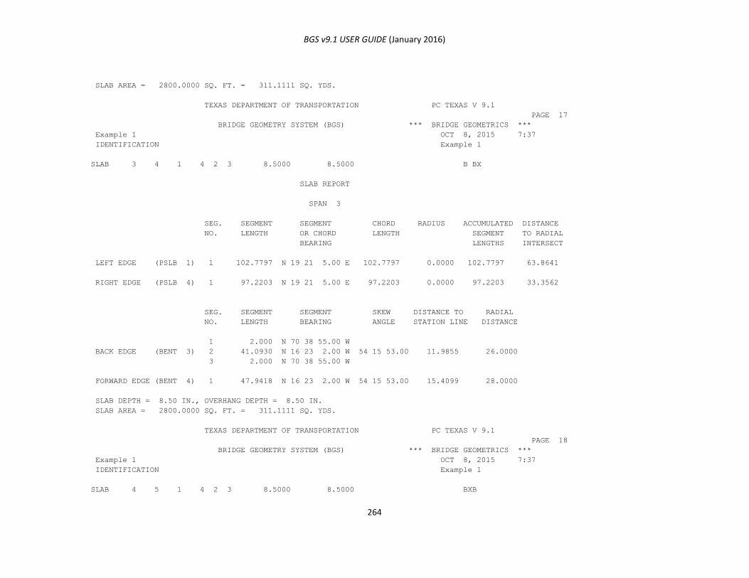
BGS v9.1 USER GUIDE (January 2016)
264
SLAB AREA = 2800.0000 SQ. FT. = 311.1111 SQ. YDS.
TEXAS DEPARTMENT OF TRANSPORTATION PC TEXAS V 9.1
PAGE 17
BRIDGE GEOMETRY SYSTEM (BGS) *** BRIDGE GEOMETRICS ***
Example 1 OCT 8, 2015 7:37
IDENTIFICATION Example 1
SLAB 3 4 1 4 2 3 8.5000 8.5000 B BX
SLAB REPORT
SPAN 3
SEG. SEGMENT SEGMENT CHORD RADIUS ACCUMULATED DISTANCE
NO. LENGTH OR CHORD LENGTH SEGMENT TO RADIAL
BEARING LENGTHS INTERSECT
LEFT EDGE (PSLB 1) 1 102.7797 N 19 21 5.00 E 102.7797 0.0000 102.7797 63.8641
RIGHT EDGE (PSLB 4) 1 97.2203 N 19 21 5.00 E 97.2203 0.0000 97.2203 33.3562
SEG. SEGMENT SEGMENT SKEW DISTANCE TO RADIAL
NO. LENGTH BEARING ANGLE STATION LINE DISTANCE
1 2.000 N 70 38 55.00 W
BACK EDGE (BENT 3) 2 41.0930 N 16 23 2.00 W 54 15 53.00 11.9855 26.0000
3 2.000 N 70 38 55.00 W
FORWARD EDGE (BENT 4) 1 47.9418 N 16 23 2.00 W 54 15 53.00 15.4099 28.0000
SLAB DEPTH = 8.50 IN., OVERHANG DEPTH = 8.50 IN.
SLAB AREA = 2800.0000 SQ. FT. = 311.1111 SQ. YDS.
TEXAS DEPARTMENT OF TRANSPORTATION PC TEXAS V 9.1
PAGE 18
BRIDGE GEOMETRY SYSTEM (BGS) *** BRIDGE GEOMETRICS ***
Example 1 OCT 8, 2015 7:37
IDENTIFICATION Example 1
SLAB 4 5 1 4 2 3 8.5000 8.5000 BXB

BGS v9.1 USER GUIDE (January 2016)
265
SLAB REPORT
SPAN 4
SEG. SEGMENT SEGMENT CHORD RADIUS ACCUMULATED DISTANCE
NO. LENGTH OR CHORD LENGTH SEGMENT TO RADIAL
BEARING LENGTHS INTERSECT
LEFT EDGE (PSLB 1) 1 37.5747 N 19 21 5.00 E 37.5747 0.0000 37.5747 24.4151
2 19.5914 N 18 36 14.58 E 19.5908 750.9999 57.1660
RIGHT EDGE (PSLB 4) 1 63.3307 N 19 21 5.00 E 63.3307 0.0000 63.3307 38.9155
SEG. SEGMENT SEGMENT SKEW DISTANCE TO RADIAL
NO. LENGTH BEARING ANGLE STATION LINE DISTANCE
BACK EDGE (BENT 4) 1 47.9418 N 16 23 2.00 W 54 15 53.00 15.4099 28.0000
1 2.000 N 72 8 35.84 W
FORWARD EDGE (BENT 5) 2 40.7953 N 17 7 53.42 W 54 15 53.00 12.0951 26.0000
3 2.000 N 70 38 55.00 W
SLAB DEPTH = 8.50 IN., OVERHANG DEPTH = 8.50 IN.
SLAB AREA = 1685.0809 SQ. FT. = 187.2312 SQ. YDS.
TEXAS DEPARTMENT OF TRANSPORTATION PC TEXAS V 9.1
PAGE 19
BRIDGE GEOMETRY SYSTEM (BGS) *** BRIDGE GEOMETRICS ***
Example 1 OCT 8, 2015 7:37
IDENTIFICATION Example 1
BRIDGE GEOMETRY LIST
CD COMMAND A B C D E F X(EAST) Y(NORTH) RADIUS,OFFSET ELEV. BEAR,AZ,SKEW STORE
NO OR CORRECTION OR STATION DISTANCE,ETC. D M S
BRNG 0 0 0 1 4 FD 12.0000 3.0000 5.5833 0.0000
BRNG 0 0 0 2 3 BO 12.0000 3.0000 5.5833 0.0000
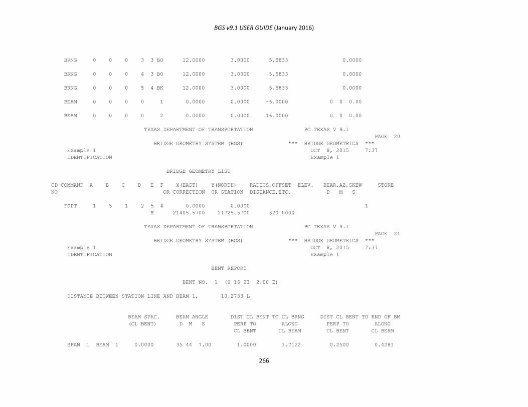
BGS v9.1 USER GUIDE (January 2016)
266
BRNG 0 0 0 3 3 BO 12.0000 3.0000 5.5833 0.0000
BRNG 0 0 0 4 3 BO 12.0000 3.0000 5.5833 0.0000
BRNG 0 0 0 5 4 BK 12.0000 3.0000 5.5833 0.0000
BEAM 0 0 0 0 1 0.0000 0.0000 -6.0000 0 0 0.00
BEAM 0 0 0 0 2 0.0000 0.0000 16.0000 0 0 0.00
TEXAS DEPARTMENT OF TRANSPORTATION PC TEXAS V 9.1
PAGE 20
BRIDGE GEOMETRY SYSTEM (BGS) *** BRIDGE GEOMETRICS ***
Example 1 OCT 8, 2015 7:37
IDENTIFICATION Example 1
BRIDGE GEOMETRY LIST
CD COMMAND A B C D E F X(EAST) Y(NORTH) RADIUS,OFFSET ELEV. BEAR,AZ,SKEW STORE
NO OR CORRECTION OR STATION DISTANCE,ETC. D M S
FOPT 1 5 1 2 5 4 0.0000 0.0000 1
H 21405.5700 21725.5700 320.0000
TEXAS DEPARTMENT OF TRANSPORTATION PC TEXAS V 9.1
PAGE 21
BRIDGE GEOMETRY SYSTEM (BGS) *** BRIDGE GEOMETRICS ***
Example 1 OCT 8, 2015 7:37
IDENTIFICATION Example 1
BENT REPORT
BENT NO. 1 (S 16 23 2.00 E)
DISTANCE BETWEEN STATION LINE AND BEAM 1, 10.2733 L
BEAM SPAC. BEAM ANGLE DIST CL BENT TO CL BRNG DIST CL BENT TO END OF BM
(CL BENT) D M S PERP TO ALONG PERP TO ALONG
CL BENT CL BEAM CL BENT CL BEAM
SPAN 1 BEAM 1 0.0000 35 44 7.00 1.0000 1.7122 0.2500 0.4281
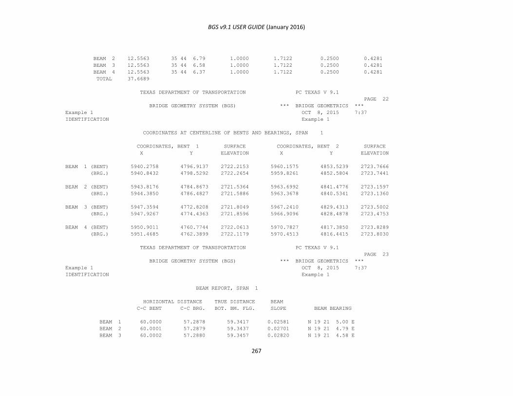
BGS v9.1 USER GUIDE (January 2016)
267
BEAM 2 12.5563 35 44 6.79 1.0000 1.7122 0.2500 0.4281
BEAM 3 12.5563 35 44 6.58 1.0000 1.7122 0.2500 0.4281
BEAM 4 12.5563 35 44 6.37 1.0000 1.7122 0.2500 0.4281
TOTAL 37.6689
TEXAS DEPARTMENT OF TRANSPORTATION PC TEXAS V 9.1
PAGE 22
BRIDGE GEOMETRY SYSTEM (BGS) *** BRIDGE GEOMETRICS ***
Example 1 OCT 8, 2015 7:37
IDENTIFICATION Example 1
COORDINATES AT CENTERLINE OF BENTS AND BEARINGS, SPAN 1
COORDINATES, BENT 1 SURFACE COORDINATES, BENT 2 SURFACE
X Y ELEVATION X Y ELEVATION
BEAM 1 (BENT) 5940.2758 4796.9137 2722.2153 5960.1575 4853.5239 2723.7666
(BRG.) 5940.8432 4798.5292 2722.2654 5959.8261 4852.5804 2723.7441
BEAM 2 (BENT) 5943.8176 4784.8673 2721.5364 5963.6992 4841.4776 2723.1597
(BRG.) 5944.3850 4786.4827 2721.5886 5963.3678 4840.5341 2723.1360
BEAM 3 (BENT) 5947.3594 4772.8208 2721.8049 5967.2410 4829.4313 2723.5002
(BRG.) 5947.9267 4774.4363 2721.8596 5966.9096 4828.4878 2723.4753
BEAM 4 (BENT) 5950.9011 4760.7744 2722.0613 5970.7827 4817.3850 2723.8289
(BRG.) 5951.4685 4762.3899 2722.1179 5970.4513 4816.4415 2723.8030
TEXAS DEPARTMENT OF TRANSPORTATION PC TEXAS V 9.1
PAGE 23
BRIDGE GEOMETRY SYSTEM (BGS) *** BRIDGE GEOMETRICS ***
Example 1 OCT 8, 2015 7:37
IDENTIFICATION Example 1
BEAM REPORT, SPAN 1
HORIZONTAL DISTANCE TRUE DISTANCE BEAM
C-C BENT C-C BRG. BOT. BM. FLG. SLOPE BEAM BEARING
BEAM 1 60.0000 57.2878 59.3417 0.02581 N 19 21 5.00 E
BEAM 2 60.0001 57.2879 59.3437 0.02701 N 19 21 4.79 E
BEAM 3 60.0002 57.2880 59.3457 0.02820 N 19 21 4.58 E
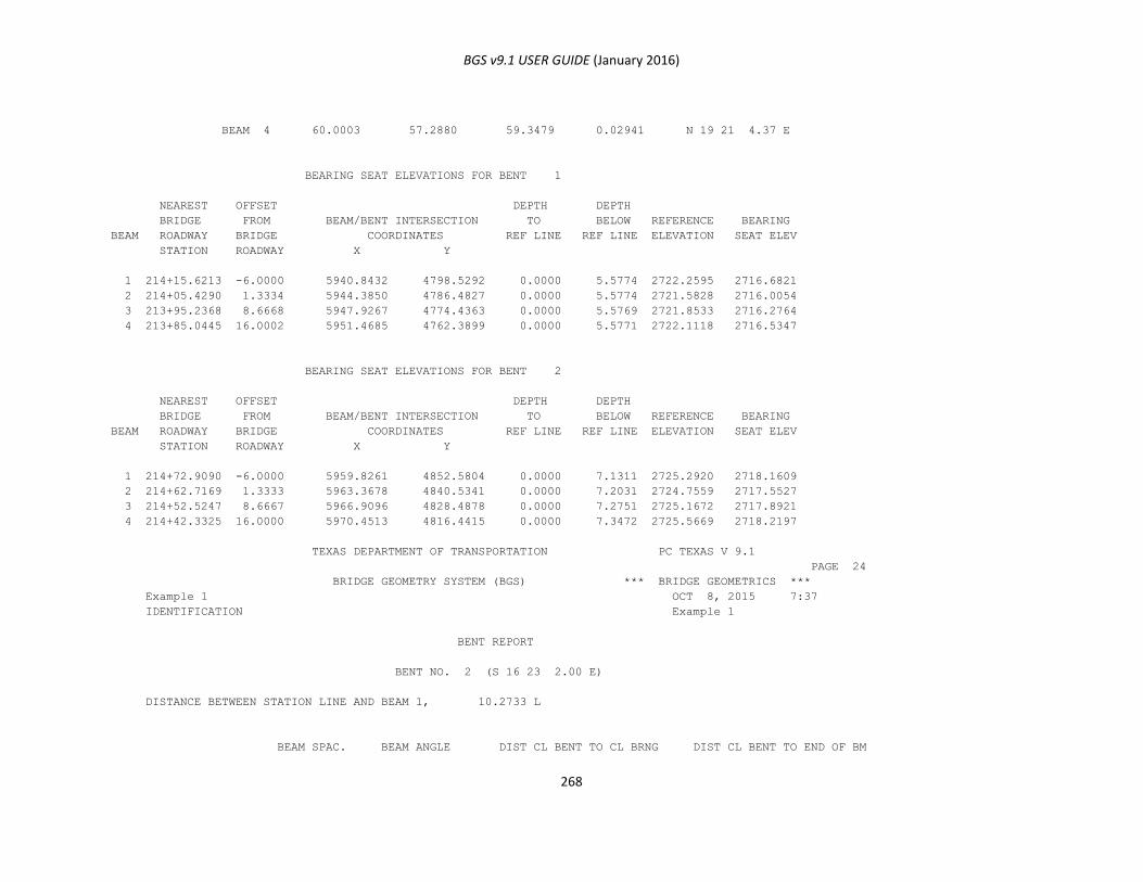
BGS v9.1 USER GUIDE (January 2016)
268
BEAM 4 60.0003 57.2880 59.3479 0.02941 N 19 21 4.37 E
BEARING SEAT ELEVATIONS FOR BENT 1
NEAREST OFFSET DEPTH DEPTH
BRIDGE FROM BEAM/BENT INTERSECTION TO BELOW REFERENCE BEARING
BEAM ROADWAY BRIDGE COORDINATES REF LINE REF LINE ELEVATION SEAT ELEV
STATION ROADWAY X Y
1 214+15.6213 -6.0000 5940.8432 4798.5292 0.0000 5.5774 2722.2595 2716.6821
2 214+05.4290 1.3334 5944.3850 4786.4827 0.0000 5.5774 2721.5828 2716.0054
3 213+95.2368 8.6668 5947.9267 4774.4363 0.0000 5.5769 2721.8533 2716.2764
4 213+85.0445 16.0002 5951.4685 4762.3899 0.0000 5.5771 2722.1118 2716.5347
BEARING SEAT ELEVATIONS FOR BENT 2
NEAREST OFFSET DEPTH DEPTH
BRIDGE FROM BEAM/BENT INTERSECTION TO BELOW REFERENCE BEARING
BEAM ROADWAY BRIDGE COORDINATES REF LINE REF LINE ELEVATION SEAT ELEV
STATION ROADWAY X Y
1 214+72.9090 -6.0000 5959.8261 4852.5804 0.0000 7.1311 2725.2920 2718.1609
2 214+62.7169 1.3333 5963.3678 4840.5341 0.0000 7.2031 2724.7559 2717.5527
3 214+52.5247 8.6667 5966.9096 4828.4878 0.0000 7.2751 2725.1672 2717.8921
4 214+42.3325 16.0000 5970.4513 4816.4415 0.0000 7.3472 2725.5669 2718.2197
TEXAS DEPARTMENT OF TRANSPORTATION PC TEXAS V 9.1
PAGE 24
BRIDGE GEOMETRY SYSTEM (BGS) *** BRIDGE GEOMETRICS ***
Example 1 OCT 8, 2015 7:37
IDENTIFICATION Example 1
BENT REPORT
BENT NO. 2 (S 16 23 2.00 E)
DISTANCE BETWEEN STATION LINE AND BEAM 1, 10.2733 L
BEAM SPAC. BEAM ANGLE DIST CL BENT TO CL BRNG DIST CL BENT TO END OF BM
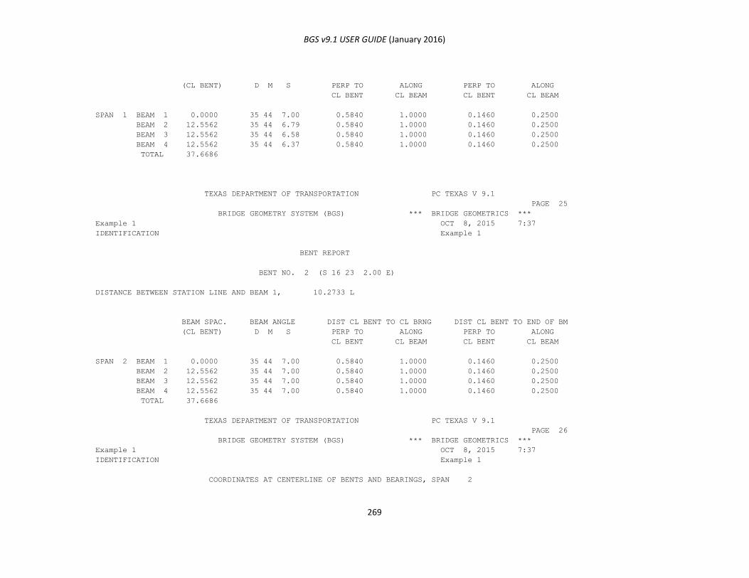
BGS v9.1 USER GUIDE (January 2016)
269
(CL BENT) D M S PERP TO ALONG PERP TO ALONG
CL BENT CL BEAM CL BENT CL BEAM
SPAN 1 BEAM 1 0.0000 35 44 7.00 0.5840 1.0000 0.1460 0.2500
BEAM 2 12.5562 35 44 6.79 0.5840 1.0000 0.1460 0.2500
BEAM 3 12.5562 35 44 6.58 0.5840 1.0000 0.1460 0.2500
BEAM 4 12.5562 35 44 6.37 0.5840 1.0000 0.1460 0.2500
TOTAL 37.6686
TEXAS DEPARTMENT OF TRANSPORTATION PC TEXAS V 9.1
PAGE 25
BRIDGE GEOMETRY SYSTEM (BGS) *** BRIDGE GEOMETRICS ***
Example 1 OCT 8, 2015 7:37
IDENTIFICATION Example 1
BENT REPORT
BENT NO. 2 (S 16 23 2.00 E)
DISTANCE BETWEEN STATION LINE AND BEAM 1, 10.2733 L
BEAM SPAC. BEAM ANGLE DIST CL BENT TO CL BRNG DIST CL BENT TO END OF BM
(CL BENT) D M S PERP TO ALONG PERP TO ALONG
CL BENT CL BEAM CL BENT CL BEAM
SPAN 2 BEAM 1 0.0000 35 44 7.00 0.5840 1.0000 0.1460 0.2500
BEAM 2 12.5562 35 44 7.00 0.5840 1.0000 0.1460 0.2500
BEAM 3 12.5562 35 44 7.00 0.5840 1.0000 0.1460 0.2500
BEAM 4 12.5562 35 44 7.00 0.5840 1.0000 0.1460 0.2500
TOTAL 37.6686
TEXAS DEPARTMENT OF TRANSPORTATION PC TEXAS V 9.1
PAGE 26
BRIDGE GEOMETRY SYSTEM (BGS) *** BRIDGE GEOMETRICS ***
Example 1 OCT 8, 2015 7:37
IDENTIFICATION Example 1
COORDINATES AT CENTERLINE OF BENTS AND BEARINGS, SPAN 2
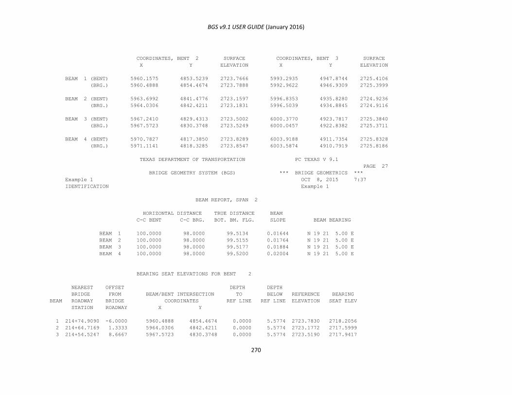
BGS v9.1 USER GUIDE (January 2016)
270
COORDINATES, BENT 2 SURFACE COORDINATES, BENT 3 SURFACE
X Y ELEVATION X Y ELEVATION
BEAM 1 (BENT) 5960.1575 4853.5239 2723.7666 5993.2935 4947.8744 2725.4106
(BRG.) 5960.4888 4854.4674 2723.7888 5992.9622 4946.9309 2725.3999
BEAM 2 (BENT) 5963.6992 4841.4776 2723.1597 5996.8353 4935.8280 2724.9236
(BRG.) 5964.0306 4842.4211 2723.1831 5996.5039 4934.8845 2724.9116
BEAM 3 (BENT) 5967.2410 4829.4313 2723.5002 6000.3770 4923.7817 2725.3840
(BRG.) 5967.5723 4830.3748 2723.5249 6000.0457 4922.8382 2725.3711
BEAM 4 (BENT) 5970.7827 4817.3850 2723.8289 6003.9188 4911.7354 2725.8328
(BRG.) 5971.1141 4818.3285 2723.8547 6003.5874 4910.7919 2725.8186
TEXAS DEPARTMENT OF TRANSPORTATION PC TEXAS V 9.1
PAGE 27
BRIDGE GEOMETRY SYSTEM (BGS) *** BRIDGE GEOMETRICS ***
Example 1 OCT 8, 2015 7:37
IDENTIFICATION Example 1
BEAM REPORT, SPAN 2
HORIZONTAL DISTANCE TRUE DISTANCE BEAM
C-C BENT C-C BRG. BOT. BM. FLG. SLOPE BEAM BEARING
BEAM 1 100.0000 98.0000 99.5134 0.01644 N 19 21 5.00 E
BEAM 2 100.0000 98.0000 99.5155 0.01764 N 19 21 5.00 E
BEAM 3 100.0000 98.0000 99.5177 0.01884 N 19 21 5.00 E
BEAM 4 100.0000 98.0000 99.5200 0.02004 N 19 21 5.00 E
BEARING SEAT ELEVATIONS FOR BENT 2
NEAREST OFFSET DEPTH DEPTH
BRIDGE FROM BEAM/BENT INTERSECTION TO BELOW REFERENCE BEARING
BEAM ROADWAY BRIDGE COORDINATES REF LINE REF LINE ELEVATION SEAT ELEV
STATION ROADWAY X Y
1 214+74.9090 -6.0000 5960.4888 4854.4674 0.0000 5.5774 2723.7830 2718.2056
2 214+64.7169 1.3333 5964.0306 4842.4211 0.0000 5.5774 2723.1772 2717.5999
3 214+54.5247 8.6667 5967.5723 4830.3748 0.0000 5.5774 2723.5190 2717.9417

BGS v9.1 USER GUIDE (January 2016)
271
4 214+44.3325 16.0000 5971.1141 4818.3285 0.0000 5.5774 2723.8489 2718.2715
BEARING SEAT ELEVATIONS FOR BENT 3
NEAREST OFFSET DEPTH DEPTH
BRIDGE FROM BEAM/BENT INTERSECTION TO BELOW REFERENCE BEARING
BEAM ROADWAY BRIDGE COORDINATES REF LINE REF LINE ELEVATION SEAT ELEV
STATION ROADWAY X Y
1 215+72.9090 -6.0000 5992.9622 4946.9309 0.0000 7.2217 2727.0383 2719.8167
2 215+62.7169 1.3333 5996.5039 4934.8845 0.0000 7.3416 2726.6699 2719.3284
3 215+52.5247 8.6667 6000.0457 4922.8382 0.0000 7.4612 2727.2490 2719.7878
4 215+42.3325 16.0000 6003.5874 4910.7919 0.0000 7.5813 2727.8167 2720.2354
TEXAS DEPARTMENT OF TRANSPORTATION PC TEXAS V 9.1
PAGE 28
BRIDGE GEOMETRY SYSTEM (BGS) *** BRIDGE GEOMETRICS ***
Example 1 OCT 8, 2015 7:37
IDENTIFICATION Example 1
BENT REPORT
BENT NO. 3 (S 16 23 2.00 E)
DISTANCE BETWEEN STATION LINE AND BEAM 1, 10.2733 L
BEAM SPAC. BEAM ANGLE DIST CL BENT TO CL BRNG DIST CL BENT TO END OF BM
(CL BENT) D M S PERP TO ALONG PERP TO ALONG
CL BENT CL BEAM CL BENT CL BEAM
SPAN 2 BEAM 1 0.0000 35 44 7.00 0.5840 1.0000 0.1460 0.2500
BEAM 2 12.5562 35 44 7.00 0.5840 1.0000 0.1460 0.2500
BEAM 3 12.5562 35 44 7.00 0.5840 1.0000 0.1460 0.2500
BEAM 4 12.5562 35 44 7.00 0.5840 1.0000 0.1460 0.2500
TOTAL 37.6686
TEXAS DEPARTMENT OF TRANSPORTATION PC TEXAS V 9.1
PAGE 29
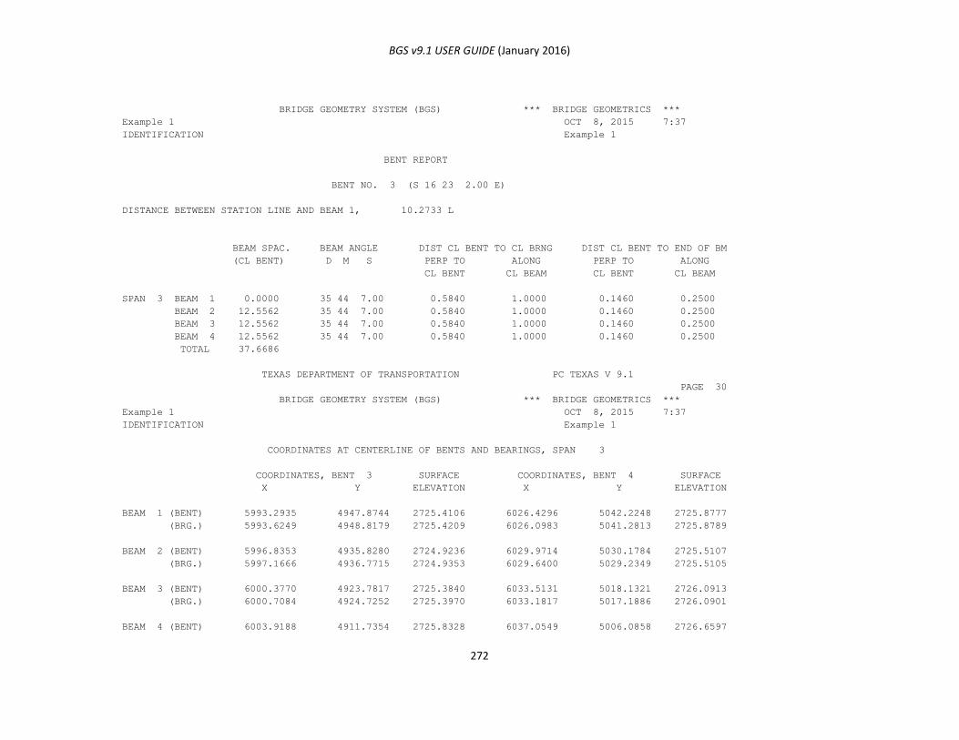
BGS v9.1 USER GUIDE (January 2016)
272
BRIDGE GEOMETRY SYSTEM (BGS) *** BRIDGE GEOMETRICS ***
Example 1 OCT 8, 2015 7:37
IDENTIFICATION Example 1
BENT REPORT
BENT NO. 3 (S 16 23 2.00 E)
DISTANCE BETWEEN STATION LINE AND BEAM 1, 10.2733 L
BEAM SPAC. BEAM ANGLE DIST CL BENT TO CL BRNG DIST CL BENT TO END OF BM
(CL BENT) D M S PERP TO ALONG PERP TO ALONG
CL BENT CL BEAM CL BENT CL BEAM
SPAN 3 BEAM 1 0.0000 35 44 7.00 0.5840 1.0000 0.1460 0.2500
BEAM 2 12.5562 35 44 7.00 0.5840 1.0000 0.1460 0.2500
BEAM 3 12.5562 35 44 7.00 0.5840 1.0000 0.1460 0.2500
BEAM 4 12.5562 35 44 7.00 0.5840 1.0000 0.1460 0.2500
TOTAL 37.6686
TEXAS DEPARTMENT OF TRANSPORTATION PC TEXAS V 9.1
PAGE 30
BRIDGE GEOMETRY SYSTEM (BGS) *** BRIDGE GEOMETRICS ***
Example 1 OCT 8, 2015 7:37
IDENTIFICATION Example 1
COORDINATES AT CENTERLINE OF BENTS AND BEARINGS, SPAN 3
COORDINATES, BENT 3 SURFACE COORDINATES, BENT 4 SURFACE
X Y ELEVATION X Y ELEVATION
BEAM 1 (BENT) 5993.2935 4947.8744 2725.4106 6026.4296 5042.2248 2725.8777
(BRG.) 5993.6249 4948.8179 2725.4209 6026.0983 5041.2813 2725.8789
BEAM 2 (BENT) 5996.8353 4935.8280 2724.9236 6029.9714 5030.1784 2725.5107
(BRG.) 5997.1666 4936.7715 2724.9353 6029.6400 5029.2349 2725.5105
BEAM 3 (BENT) 6000.3770 4923.7817 2725.3840 6033.5131 5018.1321 2726.0913
(BRG.) 6000.7084 4924.7252 2725.3970 6033.1817 5017.1886 2726.0901
BEAM 4 (BENT) 6003.9188 4911.7354 2725.8328 6037.0549 5006.0858 2726.6597
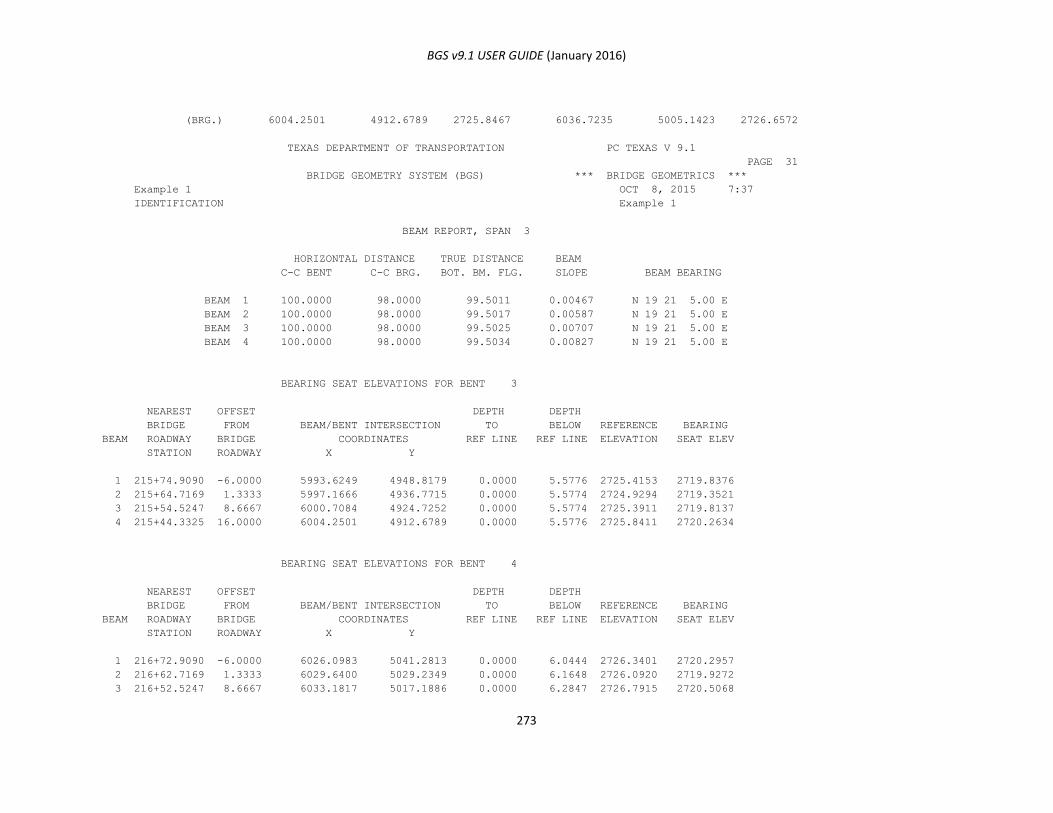
BGS v9.1 USER GUIDE (January 2016)
273
(BRG.) 6004.2501 4912.6789 2725.8467 6036.7235 5005.1423 2726.6572
TEXAS DEPARTMENT OF TRANSPORTATION PC TEXAS V 9.1
PAGE 31
BRIDGE GEOMETRY SYSTEM (BGS) *** BRIDGE GEOMETRICS ***
Example 1 OCT 8, 2015 7:37
IDENTIFICATION Example 1
BEAM REPORT, SPAN 3
HORIZONTAL DISTANCE TRUE DISTANCE BEAM
C-C BENT C-C BRG. BOT. BM. FLG. SLOPE BEAM BEARING
BEAM 1 100.0000 98.0000 99.5011 0.00467 N 19 21 5.00 E
BEAM 2 100.0000 98.0000 99.5017 0.00587 N 19 21 5.00 E
BEAM 3 100.0000 98.0000 99.5025 0.00707 N 19 21 5.00 E
BEAM 4 100.0000 98.0000 99.5034 0.00827 N 19 21 5.00 E
BEARING SEAT ELEVATIONS FOR BENT 3
NEAREST OFFSET DEPTH DEPTH
BRIDGE FROM BEAM/BENT INTERSECTION TO BELOW REFERENCE BEARING
BEAM ROADWAY BRIDGE COORDINATES REF LINE REF LINE ELEVATION SEAT ELEV
STATION ROADWAY X Y
1 215+74.9090 -6.0000 5993.6249 4948.8179 0.0000 5.5776 2725.4153 2719.8376
2 215+64.7169 1.3333 5997.1666 4936.7715 0.0000 5.5774 2724.9294 2719.3521
3 215+54.5247 8.6667 6000.7084 4924.7252 0.0000 5.5774 2725.3911 2719.8137
4 215+44.3325 16.0000 6004.2501 4912.6789 0.0000 5.5776 2725.8411 2720.2634
BEARING SEAT ELEVATIONS FOR BENT 4
NEAREST OFFSET DEPTH DEPTH
BRIDGE FROM BEAM/BENT INTERSECTION TO BELOW REFERENCE BEARING
BEAM ROADWAY BRIDGE COORDINATES REF LINE REF LINE ELEVATION SEAT ELEV
STATION ROADWAY X Y
1 216+72.9090 -6.0000 6026.0983 5041.2813 0.0000 6.0444 2726.3401 2720.2957
2 216+62.7169 1.3333 6029.6400 5029.2349 0.0000 6.1648 2726.0920 2719.9272
3 216+52.5247 8.6667 6033.1817 5017.1886 0.0000 6.2847 2726.7915 2720.5068
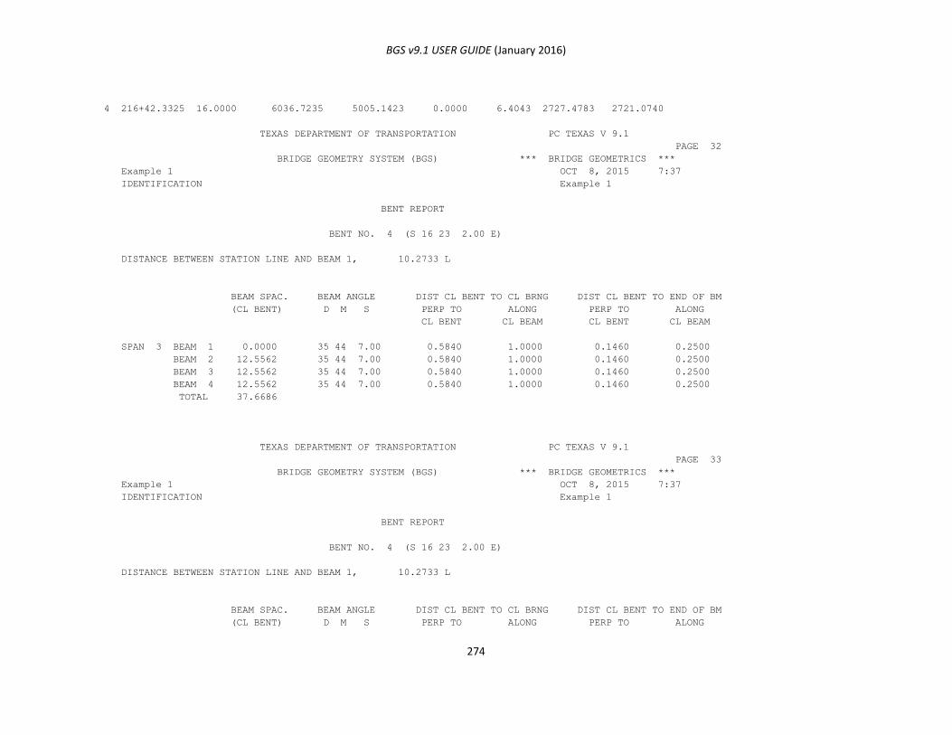
BGS v9.1 USER GUIDE (January 2016)
274
4 216+42.3325 16.0000 6036.7235 5005.1423 0.0000 6.4043 2727.4783 2721.0740
TEXAS DEPARTMENT OF TRANSPORTATION PC TEXAS V 9.1
PAGE 32
BRIDGE GEOMETRY SYSTEM (BGS) *** BRIDGE GEOMETRICS ***
Example 1 OCT 8, 2015 7:37
IDENTIFICATION Example 1
BENT REPORT
BENT NO. 4 (S 16 23 2.00 E)
DISTANCE BETWEEN STATION LINE AND BEAM 1, 10.2733 L
BEAM SPAC. BEAM ANGLE DIST CL BENT TO CL BRNG DIST CL BENT TO END OF BM
(CL BENT) D M S PERP TO ALONG PERP TO ALONG
CL BENT CL BEAM CL BENT CL BEAM
SPAN 3 BEAM 1 0.0000 35 44 7.00 0.5840 1.0000 0.1460 0.2500
BEAM 2 12.5562 35 44 7.00 0.5840 1.0000 0.1460 0.2500
BEAM 3 12.5562 35 44 7.00 0.5840 1.0000 0.1460 0.2500
BEAM 4 12.5562 35 44 7.00 0.5840 1.0000 0.1460 0.2500
TOTAL 37.6686
TEXAS DEPARTMENT OF TRANSPORTATION PC TEXAS V 9.1
PAGE 33
BRIDGE GEOMETRY SYSTEM (BGS) *** BRIDGE GEOMETRICS ***
Example 1 OCT 8, 2015 7:37
IDENTIFICATION Example 1
BENT REPORT
BENT NO. 4 (S 16 23 2.00 E)
DISTANCE BETWEEN STATION LINE AND BEAM 1, 10.2733 L
BEAM SPAC. BEAM ANGLE DIST CL BENT TO CL BRNG DIST CL BENT TO END OF BM
(CL BENT) D M S PERP TO ALONG PERP TO ALONG
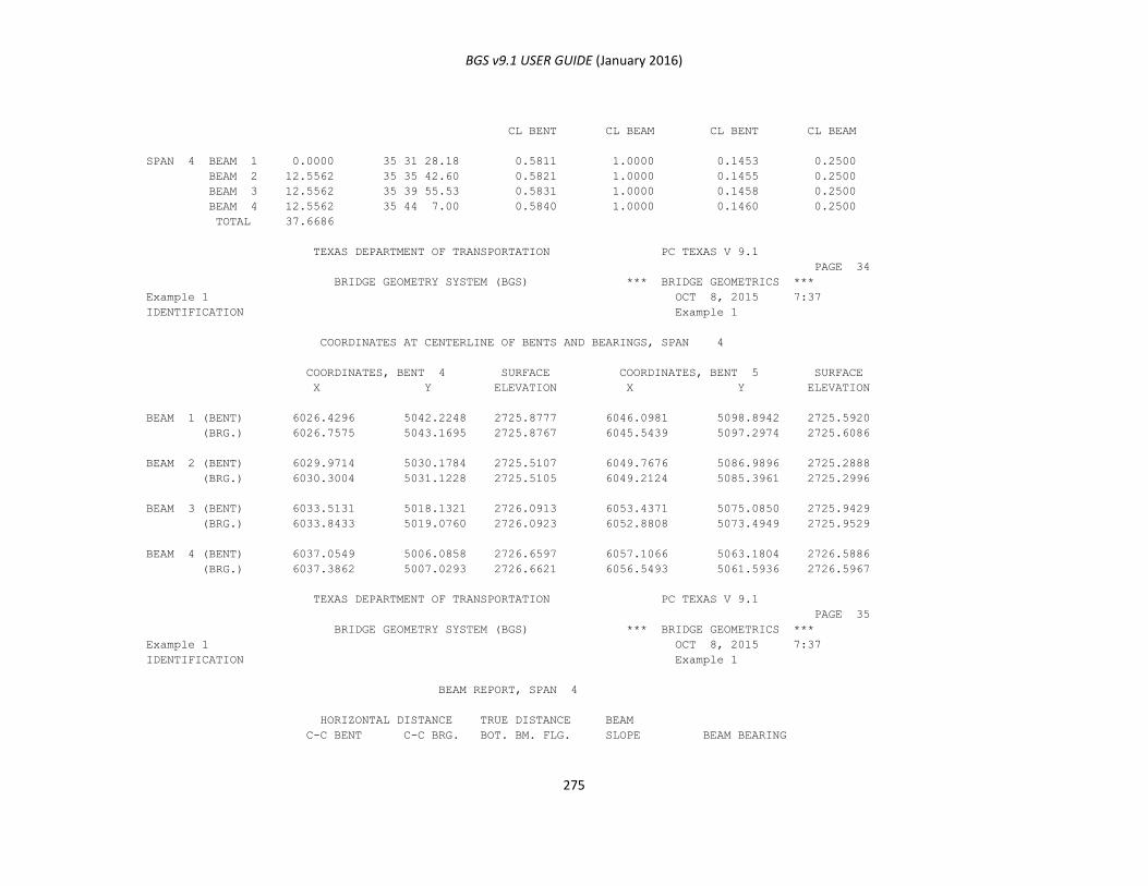
BGS v9.1 USER GUIDE (January 2016)
275
CL BENT CL BEAM CL BENT CL BEAM
SPAN 4 BEAM 1 0.0000 35 31 28.18 0.5811 1.0000 0.1453 0.2500
BEAM 2 12.5562 35 35 42.60 0.5821 1.0000 0.1455 0.2500
BEAM 3 12.5562 35 39 55.53 0.5831 1.0000 0.1458 0.2500
BEAM 4 12.5562 35 44 7.00 0.5840 1.0000 0.1460 0.2500
TOTAL 37.6686
TEXAS DEPARTMENT OF TRANSPORTATION PC TEXAS V 9.1
PAGE 34
BRIDGE GEOMETRY SYSTEM (BGS) *** BRIDGE GEOMETRICS ***
Example 1 OCT 8, 2015 7:37
IDENTIFICATION Example 1
COORDINATES AT CENTERLINE OF BENTS AND BEARINGS, SPAN 4
COORDINATES, BENT 4 SURFACE COORDINATES, BENT 5 SURFACE
X Y ELEVATION X Y ELEVATION
BEAM 1 (BENT) 6026.4296 5042.2248 2725.8777 6046.0981 5098.8942 2725.5920
(BRG.) 6026.7575 5043.1695 2725.8767 6045.5439 5097.2974 2725.6086
BEAM 2 (BENT) 6029.9714 5030.1784 2725.5107 6049.7676 5086.9896 2725.2888
(BRG.) 6030.3004 5031.1228 2725.5105 6049.2124 5085.3961 2725.2996
BEAM 3 (BENT) 6033.5131 5018.1321 2726.0913 6053.4371 5075.0850 2725.9429
(BRG.) 6033.8433 5019.0760 2726.0923 6052.8808 5073.4949 2725.9529
BEAM 4 (BENT) 6037.0549 5006.0858 2726.6597 6057.1066 5063.1804 2726.5886
(BRG.) 6037.3862 5007.0293 2726.6621 6056.5493 5061.5936 2726.5967
TEXAS DEPARTMENT OF TRANSPORTATION PC TEXAS V 9.1
PAGE 35
BRIDGE GEOMETRY SYSTEM (BGS) *** BRIDGE GEOMETRICS ***
Example 1 OCT 8, 2015 7:37
IDENTIFICATION Example 1
BEAM REPORT, SPAN 4
HORIZONTAL DISTANCE TRUE DISTANCE BEAM
C-C BENT C-C BRG. BOT. BM. FLG. SLOPE BEAM BEARING
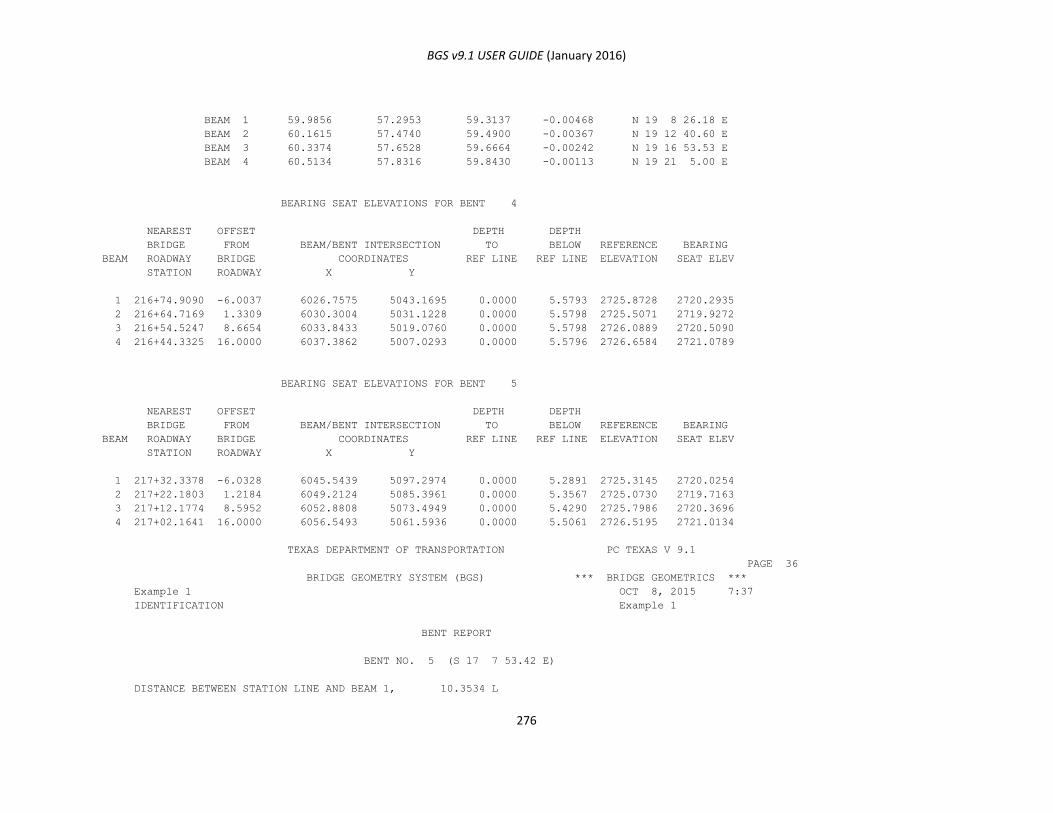
BGS v9.1 USER GUIDE (January 2016)
276
BEAM 1 59.9856 57.2953 59.3137 -0.00468 N 19 8 26.18 E
BEAM 2 60.1615 57.4740 59.4900 -0.00367 N 19 12 40.60 E
BEAM 3 60.3374 57.6528 59.6664 -0.00242 N 19 16 53.53 E
BEAM 4 60.5134 57.8316 59.8430 -0.00113 N 19 21 5.00 E
BEARING SEAT ELEVATIONS FOR BENT 4
NEAREST OFFSET DEPTH DEPTH
BRIDGE FROM BEAM/BENT INTERSECTION TO BELOW REFERENCE BEARING
BEAM ROADWAY BRIDGE COORDINATES REF LINE REF LINE ELEVATION SEAT ELEV
STATION ROADWAY X Y
1 216+74.9090 -6.0037 6026.7575 5043.1695 0.0000 5.5793 2725.8728 2720.2935
2 216+64.7169 1.3309 6030.3004 5031.1228 0.0000 5.5798 2725.5071 2719.9272
3 216+54.5247 8.6654 6033.8433 5019.0760 0.0000 5.5798 2726.0889 2720.5090
4 216+44.3325 16.0000 6037.3862 5007.0293 0.0000 5.5796 2726.6584 2721.0789
BEARING SEAT ELEVATIONS FOR BENT 5
NEAREST OFFSET DEPTH DEPTH
BRIDGE FROM BEAM/BENT INTERSECTION TO BELOW REFERENCE BEARING
BEAM ROADWAY BRIDGE COORDINATES REF LINE REF LINE ELEVATION SEAT ELEV
STATION ROADWAY X Y
1 217+32.3378 -6.0328 6045.5439 5097.2974 0.0000 5.2891 2725.3145 2720.0254
2 217+22.1803 1.2184 6049.2124 5085.3961 0.0000 5.3567 2725.0730 2719.7163
3 217+12.1774 8.5952 6052.8808 5073.4949 0.0000 5.4290 2725.7986 2720.3696
4 217+02.1641 16.0000 6056.5493 5061.5936 0.0000 5.5061 2726.5195 2721.0134
TEXAS DEPARTMENT OF TRANSPORTATION PC TEXAS V 9.1
PAGE 36
BRIDGE GEOMETRY SYSTEM (BGS) *** BRIDGE GEOMETRICS ***
Example 1 OCT 8, 2015 7:37
IDENTIFICATION Example 1
BENT REPORT
BENT NO. 5 (S 17 7 53.42 E)
DISTANCE BETWEEN STATION LINE AND BEAM 1, 10.3534 L
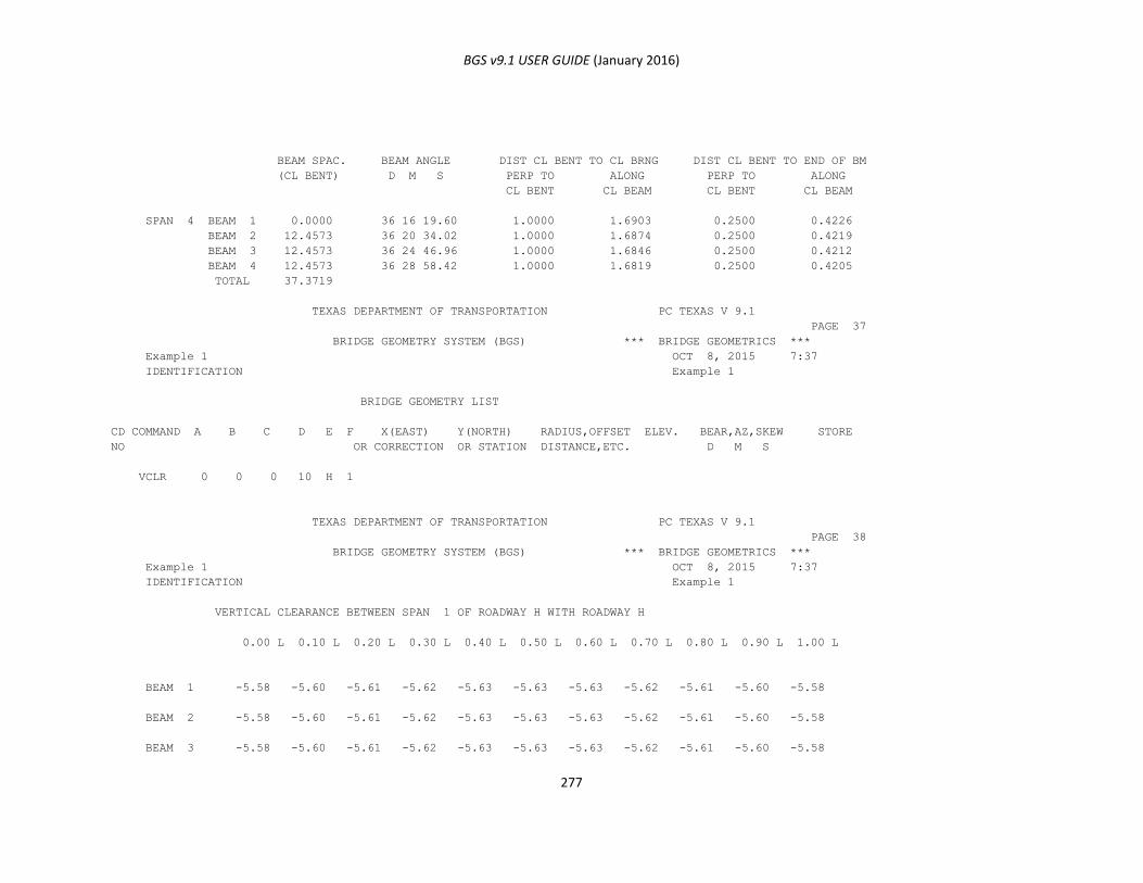
BGS v9.1 USER GUIDE (January 2016)
277
BEAM SPAC. BEAM ANGLE DIST CL BENT TO CL BRNG DIST CL BENT TO END OF BM
(CL BENT) D M S PERP TO ALONG PERP TO ALONG
CL BENT CL BEAM CL BENT CL BEAM
SPAN 4 BEAM 1 0.0000 36 16 19.60 1.0000 1.6903 0.2500 0.4226
BEAM 2 12.4573 36 20 34.02 1.0000 1.6874 0.2500 0.4219
BEAM 3 12.4573 36 24 46.96 1.0000 1.6846 0.2500 0.4212
BEAM 4 12.4573 36 28 58.42 1.0000 1.6819 0.2500 0.4205
TOTAL 37.3719
TEXAS DEPARTMENT OF TRANSPORTATION PC TEXAS V 9.1
PAGE 37
BRIDGE GEOMETRY SYSTEM (BGS) *** BRIDGE GEOMETRICS ***
Example 1 OCT 8, 2015 7:37
IDENTIFICATION Example 1
BRIDGE GEOMETRY LIST
CD COMMAND A B C D E F X(EAST) Y(NORTH) RADIUS,OFFSET ELEV. BEAR,AZ,SKEW STORE
NO OR CORRECTION OR STATION DISTANCE,ETC. D M S
VCLR 0 0 0 10 H 1
TEXAS DEPARTMENT OF TRANSPORTATION PC TEXAS V 9.1
PAGE 38
BRIDGE GEOMETRY SYSTEM (BGS) *** BRIDGE GEOMETRICS ***
Example 1 OCT 8, 2015 7:37
IDENTIFICATION Example 1
VERTICAL CLEARANCE BETWEEN SPAN 1 OF ROADWAY H WITH ROADWAY H
0.00 L 0.10 L 0.20 L 0.30 L 0.40 L 0.50 L 0.60 L 0.70 L 0.80 L 0.90 L 1.00 L
BEAM 1 -5.58 -5.60 -5.61 -5.62 -5.63 -5.63 -5.63 -5.62 -5.61 -5.60 -5.58
BEAM 2 -5.58 -5.60 -5.61 -5.62 -5.63 -5.63 -5.63 -5.62 -5.61 -5.60 -5.58
BEAM 3 -5.58 -5.60 -5.61 -5.62 -5.63 -5.63 -5.63 -5.62 -5.61 -5.60 -5.58
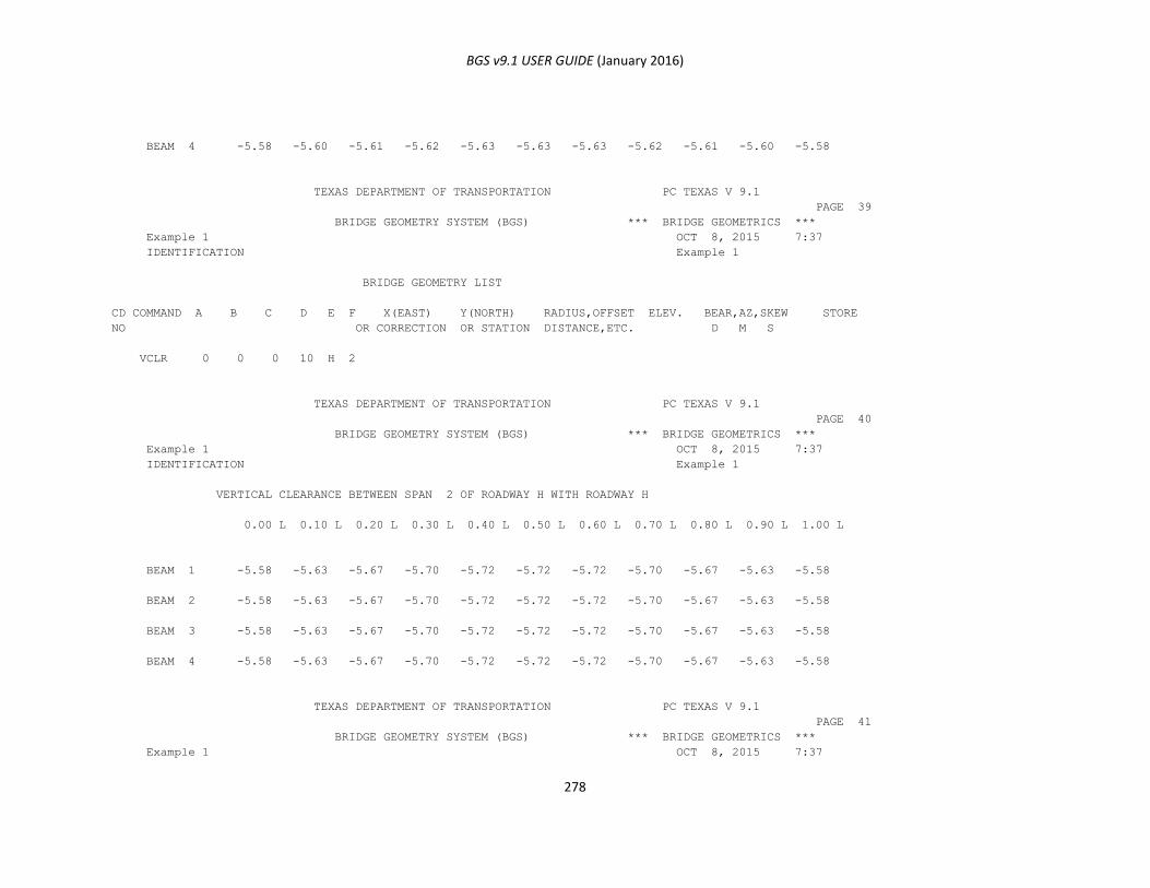
BGS v9.1 USER GUIDE (January 2016)
278
BEAM 4 -5.58 -5.60 -5.61 -5.62 -5.63 -5.63 -5.63 -5.62 -5.61 -5.60 -5.58
TEXAS DEPARTMENT OF TRANSPORTATION PC TEXAS V 9.1
PAGE 39
BRIDGE GEOMETRY SYSTEM (BGS) *** BRIDGE GEOMETRICS ***
Example 1 OCT 8, 2015 7:37
IDENTIFICATION Example 1
BRIDGE GEOMETRY LIST
CD COMMAND A B C D E F X(EAST) Y(NORTH) RADIUS,OFFSET ELEV. BEAR,AZ,SKEW STORE
NO OR CORRECTION OR STATION DISTANCE,ETC. D M S
VCLR 0 0 0 10 H 2
TEXAS DEPARTMENT OF TRANSPORTATION PC TEXAS V 9.1
PAGE 40
BRIDGE GEOMETRY SYSTEM (BGS) *** BRIDGE GEOMETRICS ***
Example 1 OCT 8, 2015 7:37
IDENTIFICATION Example 1
VERTICAL CLEARANCE BETWEEN SPAN 2 OF ROADWAY H WITH ROADWAY H
0.00 L 0.10 L 0.20 L 0.30 L 0.40 L 0.50 L 0.60 L 0.70 L 0.80 L 0.90 L 1.00 L
BEAM 1 -5.58 -5.63 -5.67 -5.70 -5.72 -5.72 -5.72 -5.70 -5.67 -5.63 -5.58
BEAM 2 -5.58 -5.63 -5.67 -5.70 -5.72 -5.72 -5.72 -5.70 -5.67 -5.63 -5.58
BEAM 3 -5.58 -5.63 -5.67 -5.70 -5.72 -5.72 -5.72 -5.70 -5.67 -5.63 -5.58
BEAM 4 -5.58 -5.63 -5.67 -5.70 -5.72 -5.72 -5.72 -5.70 -5.67 -5.63 -5.58
TEXAS DEPARTMENT OF TRANSPORTATION PC TEXAS V 9.1
PAGE 41
BRIDGE GEOMETRY SYSTEM (BGS) *** BRIDGE GEOMETRICS ***
Example 1 OCT 8, 2015 7:37
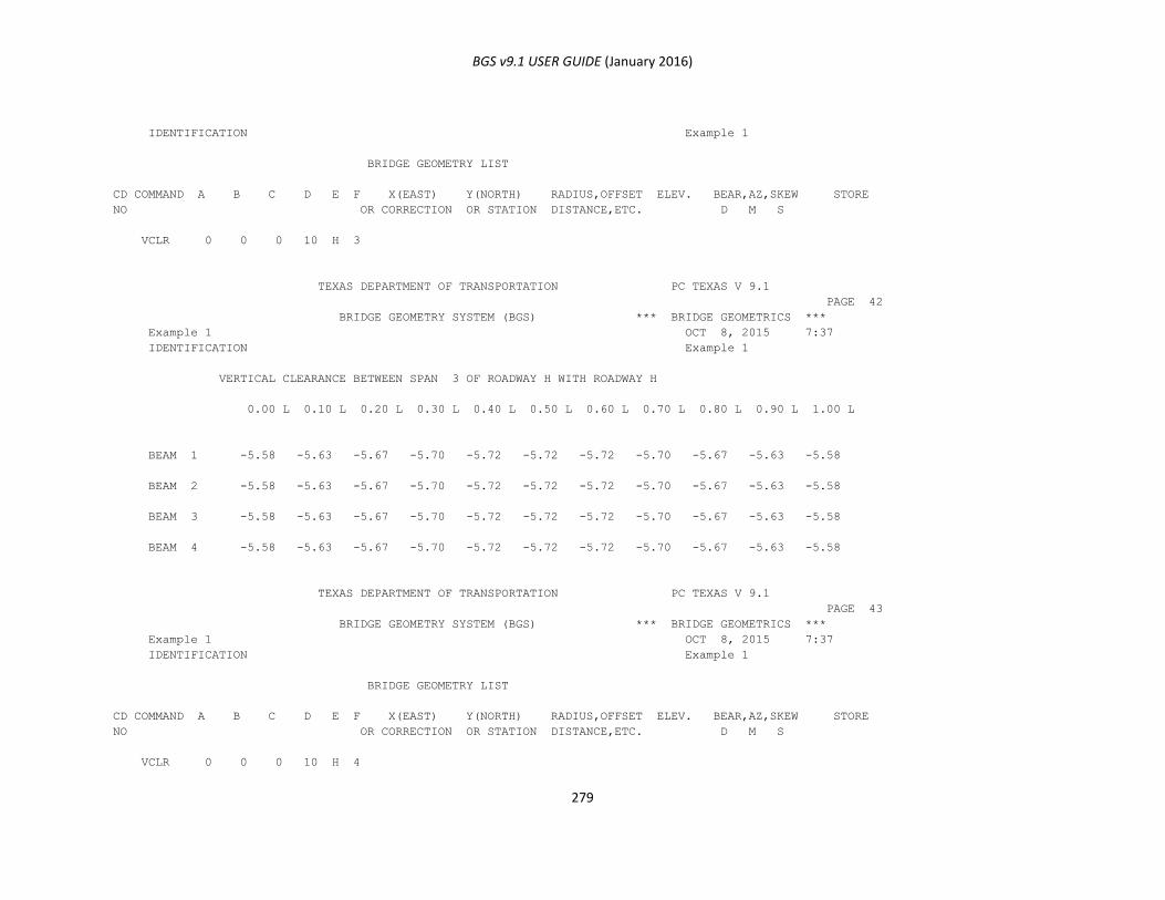
BGS v9.1 USER GUIDE (January 2016)
279
IDENTIFICATION Example 1
BRIDGE GEOMETRY LIST
CD COMMAND A B C D E F X(EAST) Y(NORTH) RADIUS,OFFSET ELEV. BEAR,AZ,SKEW STORE
NO OR CORRECTION OR STATION DISTANCE,ETC. D M S
VCLR 0 0 0 10 H 3
TEXAS DEPARTMENT OF TRANSPORTATION PC TEXAS V 9.1
PAGE 42
BRIDGE GEOMETRY SYSTEM (BGS) *** BRIDGE GEOMETRICS ***
Example 1 OCT 8, 2015 7:37
IDENTIFICATION Example 1
VERTICAL CLEARANCE BETWEEN SPAN 3 OF ROADWAY H WITH ROADWAY H
0.00 L 0.10 L 0.20 L 0.30 L 0.40 L 0.50 L 0.60 L 0.70 L 0.80 L 0.90 L 1.00 L
BEAM 1 -5.58 -5.63 -5.67 -5.70 -5.72 -5.72 -5.72 -5.70 -5.67 -5.63 -5.58
BEAM 2 -5.58 -5.63 -5.67 -5.70 -5.72 -5.72 -5.72 -5.70 -5.67 -5.63 -5.58
BEAM 3 -5.58 -5.63 -5.67 -5.70 -5.72 -5.72 -5.72 -5.70 -5.67 -5.63 -5.58
BEAM 4 -5.58 -5.63 -5.67 -5.70 -5.72 -5.72 -5.72 -5.70 -5.67 -5.63 -5.58
TEXAS DEPARTMENT OF TRANSPORTATION PC TEXAS V 9.1
PAGE 43
BRIDGE GEOMETRY SYSTEM (BGS) *** BRIDGE GEOMETRICS ***
Example 1 OCT 8, 2015 7:37
IDENTIFICATION Example 1
BRIDGE GEOMETRY LIST
CD COMMAND A B C D E F X(EAST) Y(NORTH) RADIUS,OFFSET ELEV. BEAR,AZ,SKEW STORE
NO OR CORRECTION OR STATION DISTANCE,ETC. D M S
VCLR 0 0 0 10 H 4
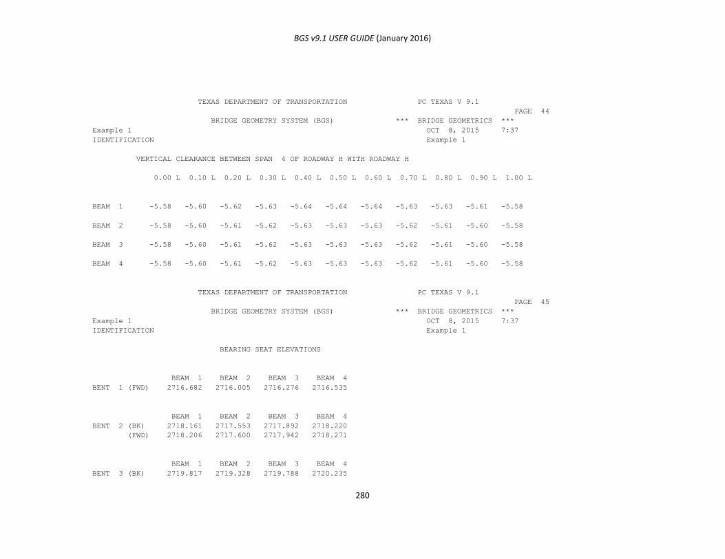
BGS v9.1 USER GUIDE (January 2016)
280
TEXAS DEPARTMENT OF TRANSPORTATION PC TEXAS V 9.1
PAGE 44
BRIDGE GEOMETRY SYSTEM (BGS) *** BRIDGE GEOMETRICS ***
Example 1 OCT 8, 2015 7:37
IDENTIFICATION Example 1
VERTICAL CLEARANCE BETWEEN SPAN 4 OF ROADWAY H WITH ROADWAY H
0.00 L 0.10 L 0.20 L 0.30 L 0.40 L 0.50 L 0.60 L 0.70 L 0.80 L 0.90 L 1.00 L
BEAM 1 -5.58 -5.60 -5.62 -5.63 -5.64 -5.64 -5.64 -5.63 -5.63 -5.61 -5.58
BEAM 2 -5.58 -5.60 -5.61 -5.62 -5.63 -5.63 -5.63 -5.62 -5.61 -5.60 -5.58
BEAM 3 -5.58 -5.60 -5.61 -5.62 -5.63 -5.63 -5.63 -5.62 -5.61 -5.60 -5.58
BEAM 4 -5.58 -5.60 -5.61 -5.62 -5.63 -5.63 -5.63 -5.62 -5.61 -5.60 -5.58
TEXAS DEPARTMENT OF TRANSPORTATION PC TEXAS V 9.1
PAGE 45
BRIDGE GEOMETRY SYSTEM (BGS) *** BRIDGE GEOMETRICS ***
Example 1 OCT 8, 2015 7:37
IDENTIFICATION Example 1
BEARING SEAT ELEVATIONS
BEAM 1 BEAM 2 BEAM 3 BEAM 4
BENT 1 (FWD) 2716.682 2716.005 2716.276 2716.535
BEAM 1 BEAM 2 BEAM 3 BEAM 4
BENT 2 (BK) 2718.161 2717.553 2717.892 2718.220
(FWD) 2718.206 2717.600 2717.942 2718.271
BEAM 1 BEAM 2 BEAM 3 BEAM 4
BENT 3 (BK) 2719.817 2719.328 2719.788 2720.235
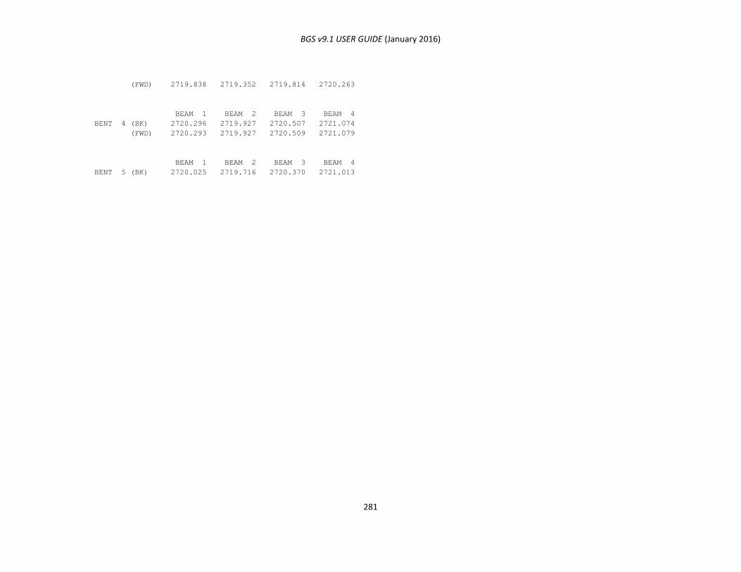
BGS v9.1 USER GUIDE (January 2016)
281
(FWD) 2719.838 2719.352 2719.814 2720.263
BEAM 1 BEAM 2 BEAM 3 BEAM 4
BENT 4 (BK) 2720.296 2719.927 2720.507 2721.074
(FWD) 2720.293 2719.927 2720.509 2721.079
BEAM 1 BEAM 2 BEAM 3 BEAM 4
BENT 5 (BK) 2720.025 2719.716 2720.370 2721.013
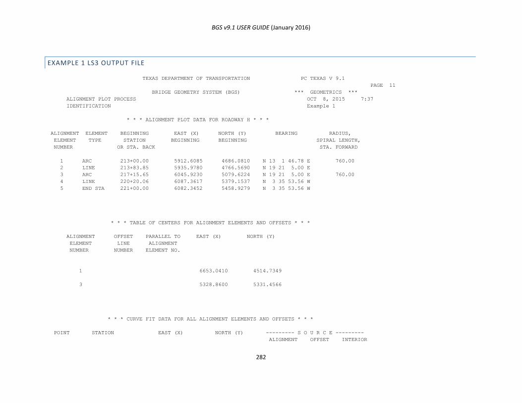
BGS v9.1 USER GUIDE (January 2016)
282
EXAMPLE 1 LS3 OUTPUT FILE
TEXAS DEPARTMENT OF TRANSPORTATION PC TEXAS V 9.1
PAGE 11
BRIDGE GEOMETRY SYSTEM (BGS) *** GEOMETRICS ***
ALIGNMENT PLOT PROCESS OCT 8, 2015 7:37
IDENTIFICATION Example 1
* * * ALIGNMENT PLOT DATA FOR ROADWAY H * * *
ALIGNMENT ELEMENT BEGINNING EAST (X) NORTH (Y) BEARING RADIUS,
ELEMENT TYPE STATION BEGINNING BEGINNING SPIRAL LENGTH,
NUMBER OR STA. BACK STA. FORWARD
1 ARC 213+00.00 5912.6085 4686.0810 N 13 1 46.78 E 760.00
2 LINE 213+83.85 5935.9780 4766.5690 N 19 21 5.00 E
3 ARC 217+15.65 6045.9230 5079.6224 N 19 21 5.00 E 760.00
4 LINE 220+20.06 6087.3617 5379.1537 N 3 35 53.56 W
5 END STA 221+00.00 6082.3452 5458.9279 N 3 35 53.56 W
* * * TABLE OF CENTERS FOR ALIGNMENT ELEMENTS AND OFFSETS * * *
ALIGNMENT OFFSET PARALLEL TO EAST (X) NORTH (Y)
ELEMENT LINE ALIGNMENT
NUMBER NUMBER ELEMENT NO.
1 6653.0410 4514.7349
3 5328.8600 5331.4566
* * * CURVE FIT DATA FOR ALL ALIGNMENT ELEMENTS AND OFFSETS * * *
POINT STATION EAST (X) NORTH (Y) --------- S O U R C E ---------
ALIGNMENT OFFSET INTERIOR
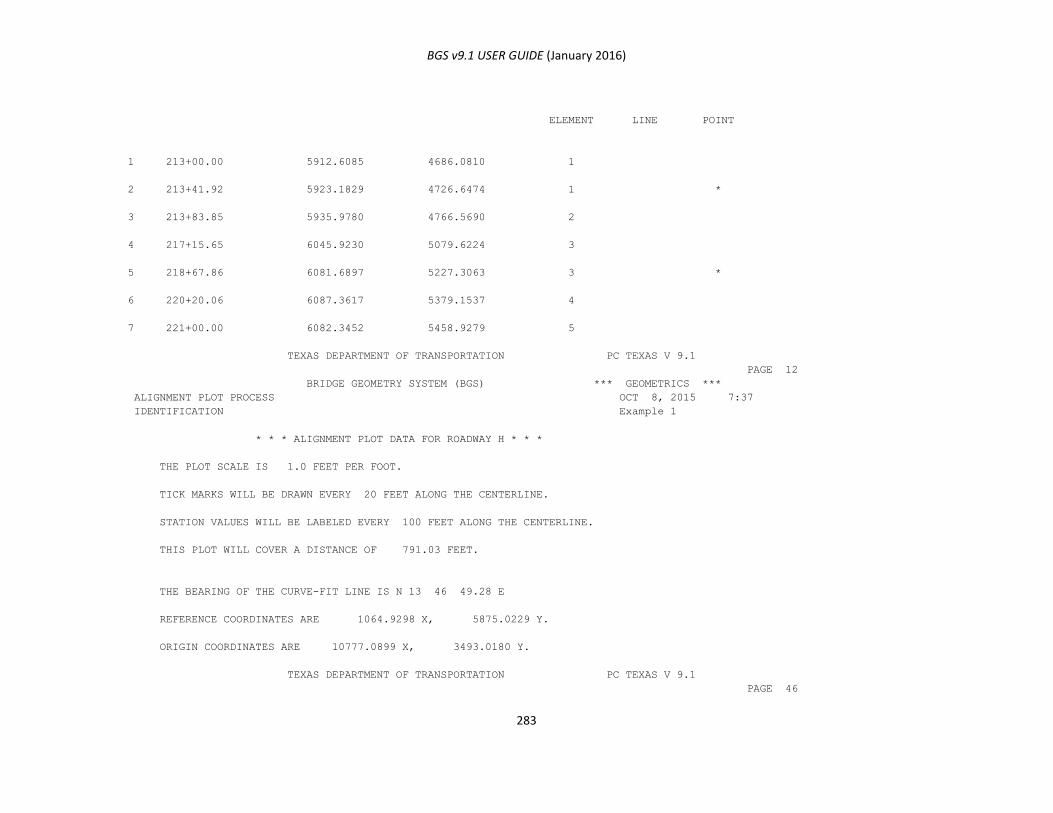
BGS v9.1 USER GUIDE (January 2016)
283
ELEMENT LINE POINT
1 213+00.00 5912.6085 4686.0810 1
2 213+41.92 5923.1829 4726.6474 1 *
3 213+83.85 5935.9780 4766.5690 2
4 217+15.65 6045.9230 5079.6224 3
5 218+67.86 6081.6897 5227.3063 3 *
6 220+20.06 6087.3617 5379.1537 4
7 221+00.00 6082.3452 5458.9279 5
TEXAS DEPARTMENT OF TRANSPORTATION PC TEXAS V 9.1
PAGE 12
BRIDGE GEOMETRY SYSTEM (BGS) *** GEOMETRICS ***
ALIGNMENT PLOT PROCESS OCT 8, 2015 7:37
IDENTIFICATION Example 1
* * * ALIGNMENT PLOT DATA FOR ROADWAY H * * *
THE PLOT SCALE IS 1.0 FEET PER FOOT.
TICK MARKS WILL BE DRAWN EVERY 20 FEET ALONG THE CENTERLINE.
STATION VALUES WILL BE LABELED EVERY 100 FEET ALONG THE CENTERLINE.
THIS PLOT WILL COVER A DISTANCE OF 791.03 FEET.
THE BEARING OF THE CURVE-FIT LINE IS N 13 46 49.28 E
REFERENCE COORDINATES ARE 1064.9298 X, 5875.0229 Y.
ORIGIN COORDINATES ARE 10777.0899 X, 3493.0180 Y.
TEXAS DEPARTMENT OF TRANSPORTATION PC TEXAS V 9.1
PAGE 46
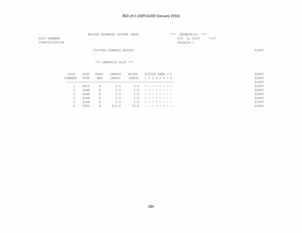
BGS v9.1 USER GUIDE (January 2016)
284
BRIDGE GEOMETRY SYSTEM (BGS) *** GEOMETRICS ***
PLOT SUMMARY OCT 8, 2015 7:37
IDENTIFICATION Example 1
PLOTTER SUMMARY REPORT PLRPT
*** GRAPHICS PLOT ***
PLOT PLOT ROAD- LENGTH WIDTH ACTIVE PENS (*) PLRPT
COMMAND TYPE WAY (FEET) (FEET) 1 2 3 4 5 6 7 8 PLRPT
----------------------------------------------------------- PLRPT
1 APLT H 0.0 0.0 * - - - - - - - PLRPT
2 SLAB H 0.0 0.0 - - - * - - - - PLRPT
3 SLAB H 0.0 0.0 - - - * - - - - PLRPT
4 SLAB H 0.0 0.0 - - - * - - - - PLRPT
5 SLAB H 0.0 0.0 - - - * - - - - PLRPT
6 FOPT H 813.0 73.0 - - - * - - - - PLRPT
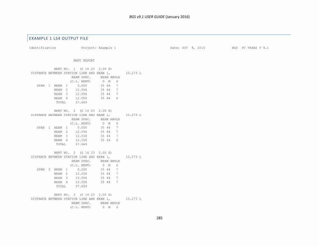
BGS v9.1 USER GUIDE (January 2016)
285
EXAMPLE 1 LS4 OUTPUT FILE
Identification Project: Example 1 Date: OCT 8, 2015 BGS PC TEXAS V 9.1
BENT REPORT
BENT NO. 1 (S 16 23 2.00 E)
DISTANCE BETWEEN STATION LINE AND BEAM 1, 10.273 L
BEAM SPAC. BEAM ANGLE
(C.L. BENT) D M S
SPAN 1 BEAM 1 0.000 35 44 7
BEAM 2 12.556 35 44 7
BEAM 3 12.556 35 44 7
BEAM 4 12.556 35 44 6
TOTAL 37.669
BENT NO. 2 (S 16 23 2.00 E)
DISTANCE BETWEEN STATION LINE AND BEAM 1, 10.273 L
BEAM SPAC. BEAM ANGLE
(C.L. BENT) D M S
SPAN 1 BEAM 1 0.000 35 44 7
BEAM 2 12.556 35 44 7
BEAM 3 12.556 35 44 7
BEAM 4 12.556 35 44 6
TOTAL 37.669
BENT NO. 2 (S 16 23 2.00 E)
DISTANCE BETWEEN STATION LINE AND BEAM 1, 10.273 L
BEAM SPAC. BEAM ANGLE
(C.L. BENT) D M S
SPAN 2 BEAM 1 0.000 35 44 7
BEAM 2 12.556 35 44 7
BEAM 3 12.556 35 44 7
BEAM 4 12.556 35 44 7
TOTAL 37.669
BENT NO. 3 (S 16 23 2.00 E)
DISTANCE BETWEEN STATION LINE AND BEAM 1, 10.273 L
BEAM SPAC. BEAM ANGLE
(C.L. BENT) D M S
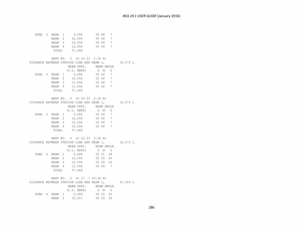
BGS v9.1 USER GUIDE (January 2016)
286
SPAN 2 BEAM 1 0.000 35 44 7
BEAM 2 12.556 35 44 7
BEAM 3 12.556 35 44 7
BEAM 4 12.556 35 44 7
TOTAL 37.669
BENT NO. 3 (S 16 23 2.00 E)
DISTANCE BETWEEN STATION LINE AND BEAM 1, 10.273 L
BEAM SPAC. BEAM ANGLE
(C.L. BENT) D M S
SPAN 3 BEAM 1 0.000 35 44 7
BEAM 2 12.556 35 44 7
BEAM 3 12.556 35 44 7
BEAM 4 12.556 35 44 7
TOTAL 37.669
BENT NO. 4 (S 16 23 2.00 E)
DISTANCE BETWEEN STATION LINE AND BEAM 1, 10.273 L
BEAM SPAC. BEAM ANGLE
(C.L. BENT) D M S
SPAN 3 BEAM 1 0.000 35 44 7
BEAM 2 12.556 35 44 7
BEAM 3 12.556 35 44 7
BEAM 4 12.556 35 44 7
TOTAL 37.669
BENT NO. 4 (S 16 23 2.00 E)
DISTANCE BETWEEN STATION LINE AND BEAM 1, 10.273 L
BEAM SPAC. BEAM ANGLE
(C.L. BENT) D M S
SPAN 4 BEAM 1 0.000 35 31 28
BEAM 2 12.556 35 35 43
BEAM 3 12.556 35 39 56
BEAM 4 12.556 35 44 7
TOTAL 37.669
BENT NO. 5 (S 17 7 53.42 E)
DISTANCE BETWEEN STATION LINE AND BEAM 1, 10.353 L
BEAM SPAC. BEAM ANGLE
(C.L. BENT) D M S
SPAN 4 BEAM 1 0.000 36 16 20
BEAM 2 12.457 36 20 34
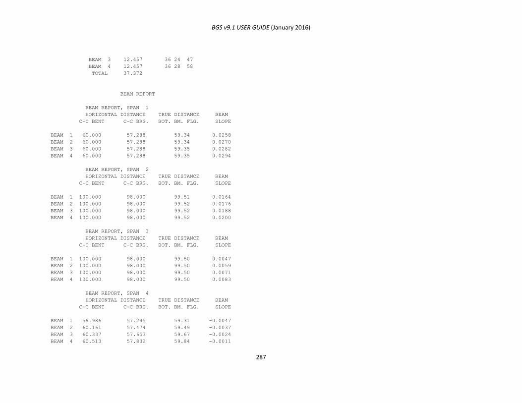
BGS v9.1 USER GUIDE (January 2016)
287
BEAM 3 12.457 36 24 47
BEAM 4 12.457 36 28 58
TOTAL 37.372
BEAM REPORT
BEAM REPORT, SPAN 1
HORIZONTAL DISTANCE TRUE DISTANCE BEAM
C-C BENT C-C BRG. BOT. BM. FLG. SLOPE
BEAM 1 60.000 57.288 59.34 0.0258
BEAM 2 60.000 57.288 59.34 0.0270
BEAM 3 60.000 57.288 59.35 0.0282
BEAM 4 60.000 57.288 59.35 0.0294
BEAM REPORT, SPAN 2
HORIZONTAL DISTANCE TRUE DISTANCE BEAM
C-C BENT C-C BRG. BOT. BM. FLG. SLOPE
BEAM 1 100.000 98.000 99.51 0.0164
BEAM 2 100.000 98.000 99.52 0.0176
BEAM 3 100.000 98.000 99.52 0.0188
BEAM 4 100.000 98.000 99.52 0.0200
BEAM REPORT, SPAN 3
HORIZONTAL DISTANCE TRUE DISTANCE BEAM
C-C BENT C-C BRG. BOT. BM. FLG. SLOPE
BEAM 1 100.000 98.000 99.50 0.0047
BEAM 2 100.000 98.000 99.50 0.0059
BEAM 3 100.000 98.000 99.50 0.0071
BEAM 4 100.000 98.000 99.50 0.0083
BEAM REPORT, SPAN 4
HORIZONTAL DISTANCE TRUE DISTANCE BEAM
C-C BENT C-C BRG. BOT. BM. FLG. SLOPE
BEAM 1 59.986 57.295 59.31 -0.0047
BEAM 2 60.161 57.474 59.49 -0.0037
BEAM 3 60.337 57.653 59.67 -0.0024
BEAM 4 60.513 57.832 59.84 -0.0011
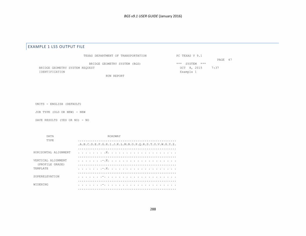
BGS v9.1 USER GUIDE (January 2016)
288
EXAMPLE 1 LS5 OUTPUT FILE
TEXAS DEPARTMENT OF TRANSPORTATION PC TEXAS V 9.1
PAGE 47
BRIDGE GEOMETRY SYSTEM (BGS) *** SYSTEM ***
BRIDGE GEOMETRY SYSTEM REQUEST OCT 8, 2015 7:37
IDENTIFICATION Example 1
RUN REPORT
UNITS - ENGLISH (DEFAULT)
JOB TYPE (OLD OR NEW) - NEW
SAVE RESULTS (YES OR NO) - NO
DATA ROADWAY
TYPE .....................................................
.A.B.C.D.E.F.G.H.I.J.K.L.M.N.O.P.Q.R.S.T.U.V.W.X.Y.Z.
.....................................................
HORIZONTAL ALIGNMENT . . . . . . . .X. . . . . . . . . . . . . . . . . . .
.....................................................
VERTICAL ALIGNMENT . . . . . . .-.X. . . . . . . . . . . . . . . . . . .
(PROFILE GRADE) .....................................................
TEMPLATE . . . . . . .-.X. . . . . . . . . . . . . . . . . . .
.....................................................
SUPERELEVATION . . . . . . .-. . . . . . . . . . . . . . . . . . . .
.....................................................
WIDENING . . . . . . .-. . . . . . . . . . . . . . . . . . . .
.....................................................
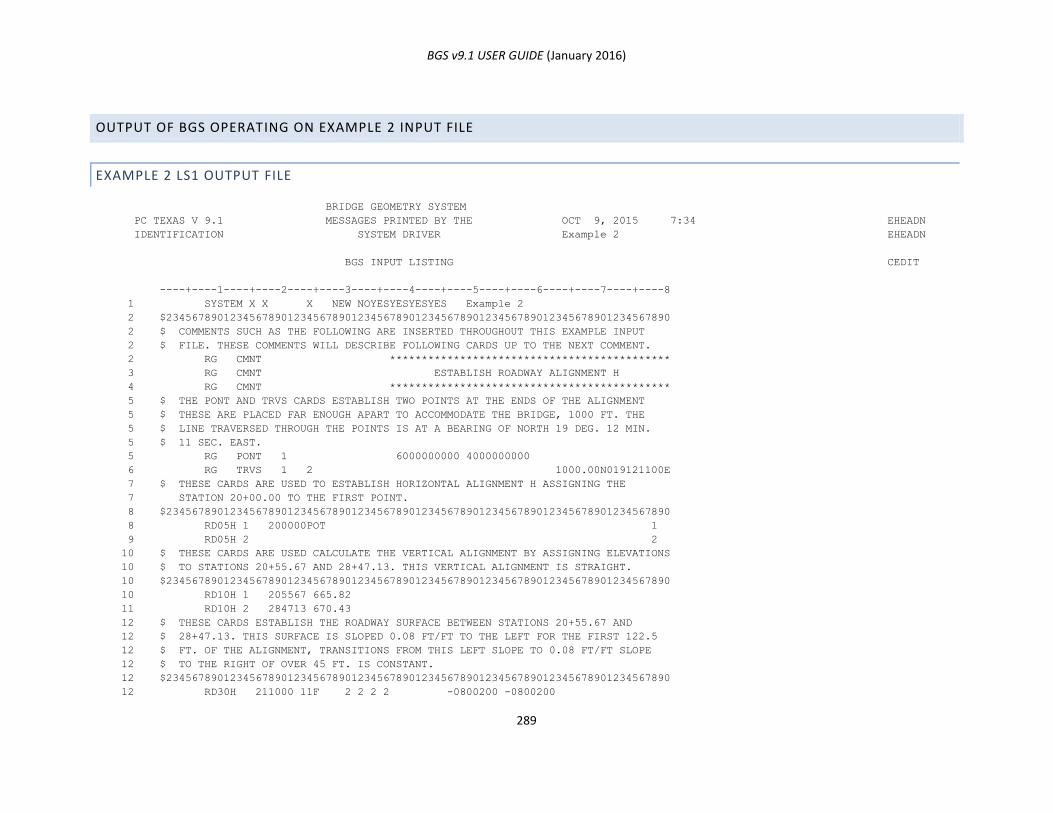
BGS v9.1 USER GUIDE (January 2016)
289
OUTPUT OF BGS OPERATING ON EXAMPLE 2 INPUT FILE
EXAMPLE 2 LS1 OUTPUT FILE
BRIDGE GEOMETRY SYSTEM
PC TEXAS V 9.1 MESSAGES PRINTED BY THE OCT 9, 2015 7:34 EHEADN
IDENTIFICATION SYSTEM DRIVER Example 2 EHEADN
BGS INPUT LISTING CEDIT
----+----1----+----2----+----3----+----4----+----5----+----6----+----7----+----8
1 SYSTEM X X X NEW NOYESYESYESYES Example 2
2 $2345678901234567890123456789012345678901234567890123456789012345678901234567890
2 $ COMMENTS SUCH AS THE FOLLOWING ARE INSERTED THROUGHOUT THIS EXAMPLE INPUT
2 $ FILE. THESE COMMENTS WILL DESCRIBE FOLLOWING CARDS UP TO THE NEXT COMMENT.
2 RG CMNT ********************************************
3 RG CMNT ESTABLISH ROADWAY ALIGNMENT H
4 RG CMNT ********************************************
5 $ THE PONT AND TRVS CARDS ESTABLISH TWO POINTS AT THE ENDS OF THE ALIGNMENT
5 $ THESE ARE PLACED FAR ENOUGH APART TO ACCOMMODATE THE BRIDGE, 1000 FT. THE
5 $ LINE TRAVERSED THROUGH THE POINTS IS AT A BEARING OF NORTH 19 DEG. 12 MIN.
5 $ 11 SEC. EAST.
5 RG PONT 1 6000000000 4000000000
6 RG TRVS 1 2 1000.00N019121100E
7 $ THESE CARDS ARE USED TO ESTABLISH HORIZONTAL ALIGNMENT H ASSIGNING THE
7 STATION 20+00.00 TO THE FIRST POINT.
8 $2345678901234567890123456789012345678901234567890123456789012345678901234567890
8 RD05H 1 200000POT 1
9 RD05H 2 2
10 $ THESE CARDS ARE USED CALCULATE THE VERTICAL ALIGNMENT BY ASSIGNING ELEVATIONS
10 $ TO STATIONS 20+55.67 AND 28+47.13. THIS VERTICAL ALIGNMENT IS STRAIGHT.
10 $2345678901234567890123456789012345678901234567890123456789012345678901234567890
10 RD10H 1 205567 665.82
11 RD10H 2 284713 670.43
12 $ THESE CARDS ESTABLISH THE ROADWAY SURFACE BETWEEN STATIONS 20+55.67 AND
12 $ 28+47.13. THIS SURFACE IS SLOPED 0.08 FT/FT TO THE LEFT FOR THE FIRST 122.5
12 $ FT. OF THE ALIGNMENT, TRANSITIONS FROM THIS LEFT SLOPE TO 0.08 FT/FT SLOPE
12 $ TO THE RIGHT OF OVER 45 FT. IS CONSTANT.
12 $2345678901234567890123456789012345678901234567890123456789012345678901234567890
12 RD30H 211000 11F 2 2 2 2 -0800200 -0800200
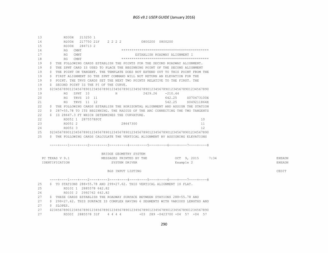
BGS v9.1 USER GUIDE (January 2016)
290
13 RD30H 213250 1
14 RD30H 217750 21F 2 2 2 2 0800200 0800200
15 RD30H 284713 2
16 RG CMNT ********************************************
17 RG CMNT ESTABLISH ROADWAY ALIGNMENT I
18 RG CMNT ********************************************
19 $ THE FOLLOWING CARDS ESTABLISH THE POINTS FOR THE SECOND ROADWAY ALIGNMENT.
19 $ THE ZPNT CARD IS USED TO PLACE THE BEGINNING POINT OF THE SECOND ALIGNMENT
19 $ THE POINT ON TANGENT. THE TEMPLATE DOES NOT EXTEND OUT TO THIS POINT FROM THE
19 $ FIRST ALIGNMENT SO THE ZPNT COMMAND WILL NOT RETURN AN ELEVATION FOR THE
19 $ POINT. THE TRVS CARDS SET THE NEXT TWO POINTS RELATIVE TO THE FIRST. THE
19 $ SECOND POINT IS THE PI OF THE CURVE.
19 $2345678901234567890123456789012345678901234567890123456789012345678901234567890
19 RG ZPNT 10 H 2429.26 -210.44
20 RG TRVS 10 11 642.25 S070473100E
21 RG TRVS 11 12 542.25 S049211864E
22 $ THE FOLLOWING CARDS ESTABLISH THE HORIZONTAL ALIGNMENT AND ASSIGN THE STATION
22 $ 287+55.78 TO ITS BEGINNING. THE RADIUS OF THE ARC CONNECTING THE TWO TANGENTS
22 $ IS 28647.3 FT WHICH DETERMINES THE CURVATURE.
22 RD05I 1 2875578POT 10
23 RD05I 2 28647300 11
24 RD05I 3 12
25 $2345678901234567890123456789012345678901234567890123456789012345678901234567890
25 $ THE FOLLOWING CARDS CALCULATE THE VERTICAL ALIGNMENT BY ASSIGNING ELEVATIONS
----+----1----+----2----+----3----+----4----+----5----+----6----+----7----+----8
BRIDGE GEOMETRY SYSTEM
PC TEXAS V 9.1 MESSAGES PRINTED BY THE OCT 9, 2015 7:34 EHEADN
IDENTIFICATION SYSTEM DRIVER Example 2 EHEADN
BGS INPUT LISTING CEDIT
----+----1----+----2----+----3----+----4----+----5----+----6----+----7----+----8
25 $ TO STATIONS 288+55.78 AND 299+27.62. THIS VERTICAL ALIGNMENT IS FLAT.
25 RD10I 1 2885578 642.82
26 RD10I 2 2992762 642.82
27 $ THESE CARDS ESTABLISH THE ROADWAY SURFACE BETWEEN STATIONS 288+55.78 AND
27 $ 299+27.62. THIS SURFACE IS COMPLEX HAVING 6 SEGMENTS WITH VARIOUS LENGTHS AND
27 $ SLOPES.
27 $2345678901234567890123456789012345678901234567890123456789012345678901234567890
27 RD30I 2885578 31F 4 4 4 4 +03 289 -0423700 +04 57 +04 57
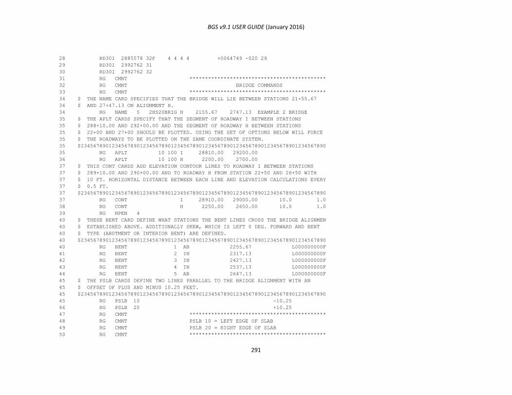
BGS v9.1 USER GUIDE (January 2016)
291
28 RD30I 2885578 32F 4 4 4 4 +0064749 -020 29
29 RD30I 2992762 31
30 RD30I 2992762 32
31 RG CMNT ********************************************
32 RG CMNT BRIDGE COMMANDS
33 RG CMNT ********************************************
34 $ THE NAME CARD SPECIFIES THAT THE BRIDGE WILL LIE BETWEEN STATIONS 21+55.67
34 $ AND 27+47.13 ON ALIGNMENT H.
34 RG NAME 5 2HS20BRIG H 2155.67 2747.13 EXAMPLE 2 BRIDGE
35 $ THE APLT CARDS SPECIFY THAT THE SEGMENT OF ROADWAY I BETWEEN STATIONS
35 $ 288+10.00 AND 292+00.00 AND THE SEGMENT OF ROADWAY H BETWEEN STATIONS
35 $ 22+00 AND 27+00 SHOULD BE PLOTTED. USING THE SET OF OPTIONS BELOW WILL FORCE
35 $ THE ROADWAYS TO BE PLOTTED ON THE SAME COORDINATE SYSTEM.
35 $2345678901234567890123456789012345678901234567890123456789012345678901234567890
35 RG APLT 10 100 I 28810.00 29200.00
36 RG APLT 10 100 H 2200.00 2700.00
37 $ THIS CONT CARDS ADD ELEVATION CONTOUR LINES TO ROADWAY I BETWEEN STATIONS
37 $ 289+10.00 AND 290+00.00 AND TO ROADWAY H FROM STATION 22+50 AND 26+50 WITH
37 $ 10 FT. HORIZONTAL DISTANCE BETWEEN EACH LINE AND ELEVATION CALCULATIONS EVERY
37 $ 0.5 FT.
37 $2345678901234567890123456789012345678901234567890123456789012345678901234567890
37 RG CONT I 28910.00 29000.00 10.0 1.0
38 RG CONT H 2250.00 2650.00 10.0 1.0
39 RG NPEN 4
40 $ THESE BENT CARD DEFINE WHAT STATIONS THE BENT LINES CROSS THE BRIDGE ALIGNMEN
40 $ ESTABLISHED ABOVE. ADDITIONALLY SKEW, WHICH IS LEFT 0 DEG. FORWARD AND BENT
40 $ TYPE (ABUTMENT OR INTERIOR BENT) ARE DEFINED.
40 $2345678901234567890123456789012345678901234567890123456789012345678901234567890
40 RG BENT 1 AB 2255.67 L000000000F
41 RG BENT 2 IN 2317.13 L000000000F
42 RG BENT 3 IN 2427.13 L000000000F
43 RG BENT 4 IN 2537.13 L000000000F
44 RG BENT 5 AB 2647.13 L000000000F
45 $ THE PSLB CARDS DEFINE TWO LINES PARALLEL TO THE BRIDGE ALIGNMENT WITH AN
45 $ OFFSET OF PLUS AND MINUS 10.25 FEET.
45 $2345678901234567890123456789012345678901234567890123456789012345678901234567890
45 RG PSLB 10 -10.25
46 RG PSLB 20 +10.25
47 RG CMNT ********************************************
48 RG CMNT PSLB 10 = LEFT EDGE OF SLAB
49 RG CMNT PSLB 20 = RIGHT EDGE OF SLAB
50 RG CMNT ********************************************
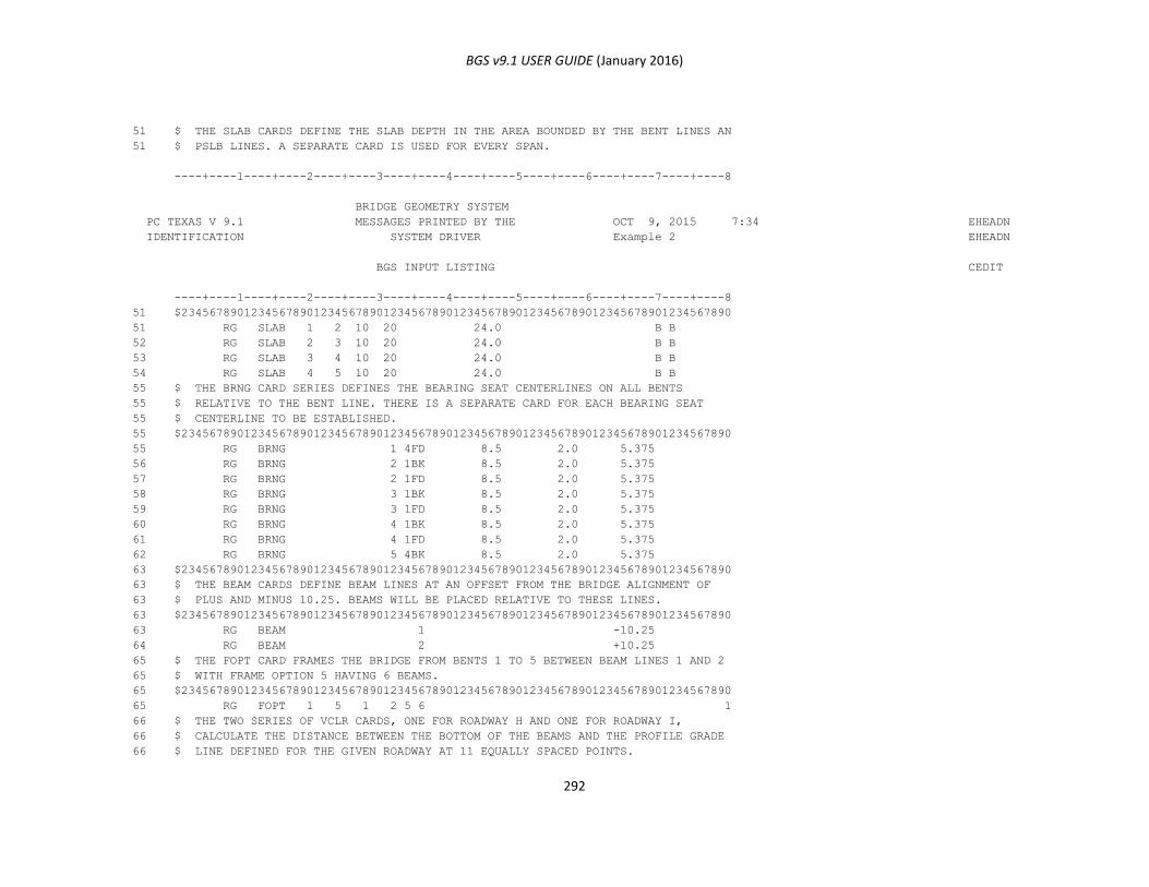
BGS v9.1 USER GUIDE (January 2016)
292
51 $ THE SLAB CARDS DEFINE THE SLAB DEPTH IN THE AREA BOUNDED BY THE BENT LINES AN
51 $ PSLB LINES. A SEPARATE CARD IS USED FOR EVERY SPAN.
----+----1----+----2----+----3----+----4----+----5----+----6----+----7----+----8
BRIDGE GEOMETRY SYSTEM
PC TEXAS V 9.1 MESSAGES PRINTED BY THE OCT 9, 2015 7:34 EHEADN
IDENTIFICATION SYSTEM DRIVER Example 2 EHEADN
BGS INPUT LISTING CEDIT
----+----1----+----2----+----3----+----4----+----5----+----6----+----7----+----8
51 $2345678901234567890123456789012345678901234567890123456789012345678901234567890
51 RG SLAB 1 2 10 20 24.0 B B
52 RG SLAB 2 3 10 20 24.0 B B
53 RG SLAB 3 4 10 20 24.0 B B
54 RG SLAB 4 5 10 20 24.0 B B
55 $ THE BRNG CARD SERIES DEFINES THE BEARING SEAT CENTERLINES ON ALL BENTS
55 $ RELATIVE TO THE BENT LINE. THERE IS A SEPARATE CARD FOR EACH BEARING SEAT
55 $ CENTERLINE TO BE ESTABLISHED.
55 $2345678901234567890123456789012345678901234567890123456789012345678901234567890
55 RG BRNG 1 4FD 8.5 2.0 5.375
56 RG BRNG 2 1BK 8.5 2.0 5.375
57 RG BRNG 2 1FD 8.5 2.0 5.375
58 RG BRNG 3 1BK 8.5 2.0 5.375
59 RG BRNG 3 1FD 8.5 2.0 5.375
60 RG BRNG 4 1BK 8.5 2.0 5.375
61 RG BRNG 4 1FD 8.5 2.0 5.375
62 RG BRNG 5 4BK 8.5 2.0 5.375
63 $2345678901234567890123456789012345678901234567890123456789012345678901234567890
63 $ THE BEAM CARDS DEFINE BEAM LINES AT AN OFFSET FROM THE BRIDGE ALIGNMENT OF
63 $ PLUS AND MINUS 10.25. BEAMS WILL BE PLACED RELATIVE TO THESE LINES.
63 $2345678901234567890123456789012345678901234567890123456789012345678901234567890
63 RG BEAM 1 -10.25
64 RG BEAM 2 +10.25
65 $ THE FOPT CARD FRAMES THE BRIDGE FROM BENTS 1 TO 5 BETWEEN BEAM LINES 1 AND 2
65 $ WITH FRAME OPTION 5 HAVING 6 BEAMS.
65 $2345678901234567890123456789012345678901234567890123456789012345678901234567890
65 RG FOPT 1 5 1 2 5 6 1
66 $ THE TWO SERIES OF VCLR CARDS, ONE FOR ROADWAY H AND ONE FOR ROADWAY I,
66 $ CALCULATE THE DISTANCE BETWEEN THE BOTTOM OF THE BEAMS AND THE PROFILE GRADE
66 $ LINE DEFINED FOR THE GIVEN ROADWAY AT 11 EQUALLY SPACED POINTS.
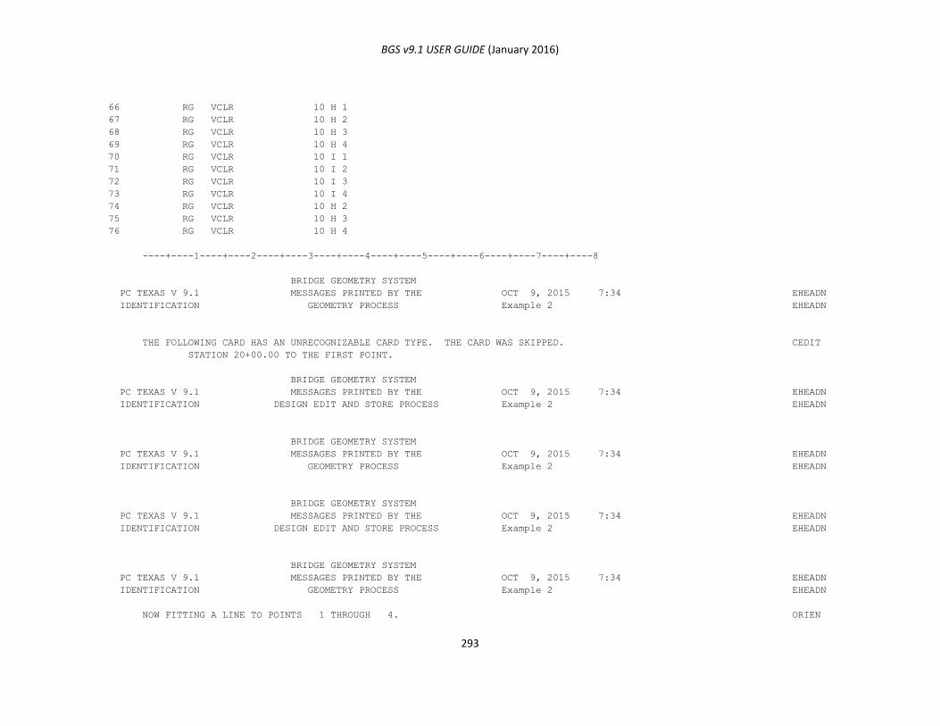
BGS v9.1 USER GUIDE (January 2016)
293
66 RG VCLR 10 H 1
67 RG VCLR 10 H 2
68 RG VCLR 10 H 3
69 RG VCLR 10 H 4
70 RG VCLR 10 I 1
71 RG VCLR 10 I 2
72 RG VCLR 10 I 3
73 RG VCLR 10 I 4
74 RG VCLR 10 H 2
75 RG VCLR 10 H 3
76 RG VCLR 10 H 4
----+----1----+----2----+----3----+----4----+----5----+----6----+----7----+----8
BRIDGE GEOMETRY SYSTEM
PC TEXAS V 9.1 MESSAGES PRINTED BY THE OCT 9, 2015 7:34 EHEADN
IDENTIFICATION GEOMETRY PROCESS Example 2 EHEADN
THE FOLLOWING CARD HAS AN UNRECOGNIZABLE CARD TYPE. THE CARD WAS SKIPPED. CEDIT
STATION 20+00.00 TO THE FIRST POINT.
BRIDGE GEOMETRY SYSTEM
PC TEXAS V 9.1 MESSAGES PRINTED BY THE OCT 9, 2015 7:34 EHEADN
IDENTIFICATION DESIGN EDIT AND STORE PROCESS Example 2 EHEADN
BRIDGE GEOMETRY SYSTEM
PC TEXAS V 9.1 MESSAGES PRINTED BY THE OCT 9, 2015 7:34 EHEADN
IDENTIFICATION GEOMETRY PROCESS Example 2 EHEADN
BRIDGE GEOMETRY SYSTEM
PC TEXAS V 9.1 MESSAGES PRINTED BY THE OCT 9, 2015 7:34 EHEADN
IDENTIFICATION DESIGN EDIT AND STORE PROCESS Example 2 EHEADN
BRIDGE GEOMETRY SYSTEM
PC TEXAS V 9.1 MESSAGES PRINTED BY THE OCT 9, 2015 7:34 EHEADN
IDENTIFICATION GEOMETRY PROCESS Example 2 EHEADN
NOW FITTING A LINE TO POINTS 1 THROUGH 4. ORIEN
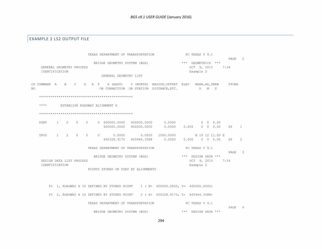
BGS v9.1 USER GUIDE (January 2016)
294
EXAMPLE 2 LS2 OUTPUT FILE
TEXAS DEPARTMENT OF TRANSPORTATION PC TEXAS V 9.1
PAGE 2
BRIDGE GEOMETRY SYSTEM (BGS) *** GEOMETRICS ***
GENERAL GEOMETRY PROCESS OCT 9, 2015 7:34
IDENTIFICATION Example 2
GENERAL GEOMETRY LIST
CD COMMAND A B C D E F X (EAST) Y (NORTH) RADIUS,OFFSET ELEV BEAR,AZ,SKEW STORE
NO OR CORRECTION OR STATION DISTANCE,ETC. D M S
************************************************
**** ESTABLISH ROADWAY ALIGNMENT H
************************************************
PONT 1 0 0 0 0 600000.0000 400000.0000 0.0000 0 0 0.00
600000.0000 400000.0000 0.0000 0.000 0 0 0.00 SP 1
TRVS 1 2 0 0 0 0.0000 0.0000 1000.0000 N 19 12 11.00 E
600328.9170 400944.3588 0.0000 0.000 0 0 0.00 SP 2
TEXAS DEPARTMENT OF TRANSPORTATION PC TEXAS V 9.1
PAGE 3
BRIDGE GEOMETRY SYSTEM (BGS) *** DESIGN DATA ***
DESIGN DATA LIST PROCESS OCT 9, 2015 7:34
IDENTIFICATION Example 2
POINTS STORED OR USED BY ALIGNMENTS
PI 1, ROADWAY H IS DEFINED BY STORED POINT 1 ( X= 600000.0000, Y= 400000.0000)
PI 2, ROADWAY H IS DEFINED BY STORED POINT 2 ( X= 600328.9170, Y= 400944.3588)
TEXAS DEPARTMENT OF TRANSPORTATION PC TEXAS V 9.1
PAGE 4
BRIDGE GEOMETRY SYSTEM (BGS) *** DESIGN DATA ***
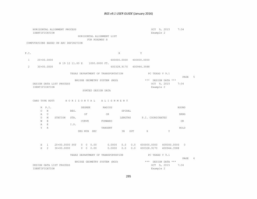
BGS v9.1 USER GUIDE (January 2016)
295
HORIZONTAL ALIGNMENT PROCESS OCT 9, 2015 7:34
IDENTIFICATION Example 2
HORIZONTAL ALIGNMENT LIST
FOR ROADWAY H
COMPUTATIONS BASED ON ARC DEFINITION
P.I. X Y
1 20+00.0000 600000.0000 400000.0000
N 19 12 11.00 E 1000.0000 FT.
2 30+00.0000 600328.9170 400944.3588
TEXAS DEPARTMENT OF TRANSPORTATION PC TEXAS V 9.1
PAGE 5
BRIDGE GEOMETRY SYSTEM (BGS) *** DESIGN DATA ***
DESIGN DATA LIST PROCESS OCT 9, 2015 7:34
IDENTIFICATION Example 2
SORTED DESIGN DATA
CARD TYPE RD05 H O R I Z O N T A L A L I G N M E N T
R P.I. DEGREE RADIUS ROUND
O N BEG. SPIRAL
A U OF OR BRNG
D M STATION STA. LENGTHS P.I. COORDINATES
W B CURVE FORWARD OR
A E I.D.
Y R TANGENT HOLD
DEG MIN SEC IN OUT X Y
H 1 20+00.0000 POT 0 0 0.00 0.0000 0.0 0.0 600000.0000 400000.0000 0
H 2 30+00.0000 0 0 0.00 0.0000 0.0 0.0 600328.9170 400944.3588
TEXAS DEPARTMENT OF TRANSPORTATION PC TEXAS V 9.1
PAGE 6
BRIDGE GEOMETRY SYSTEM (BGS) *** DESIGN DATA ***
DESIGN DATA LIST PROCESS OCT 9, 2015 7:34
IDENTIFICATION Example 2

BGS v9.1 USER GUIDE (January 2016)
296
SORTED DESIGN DATA
CARD TYPE RD10 P R O F I L E G R A D E
R P.I. FIRST SECOND
O N VERTICAL
A U VERTICAL VERTICAL ELEVATION
D M P.I. P.I. EXTERNAL GRADE
W B CURVE CURVE CORRECTION
A E STATION ELEVATION
Y R LENGTH LENGTH
H 1 20+55.67 665.82 0. 0. 0.00
H 2 28+47.13 670.43 0. 0. 0.00 0.005825
TEXAS DEPARTMENT OF TRANSPORTATION PC TEXAS V 9.1
PAGE 7
BRIDGE GEOMETRY SYSTEM (BGS) *** DESIGN DATA ***
DESIGN DATA LIST PROCESS OCT 9, 2015 7:34
IDENTIFICATION Example 2
SORTED DESIGN DATA
CARD TYPE RD30 T E M P L A T E
R
O TEMPLATE
A
D STATION STORE/
W RECALL
A
Y NO.
H 21+10.00 1
H 21+32.50 1
H 21+77.50 2
H 28+47.13 2
TEXAS DEPARTMENT OF TRANSPORTATION PC TEXAS V 9.1
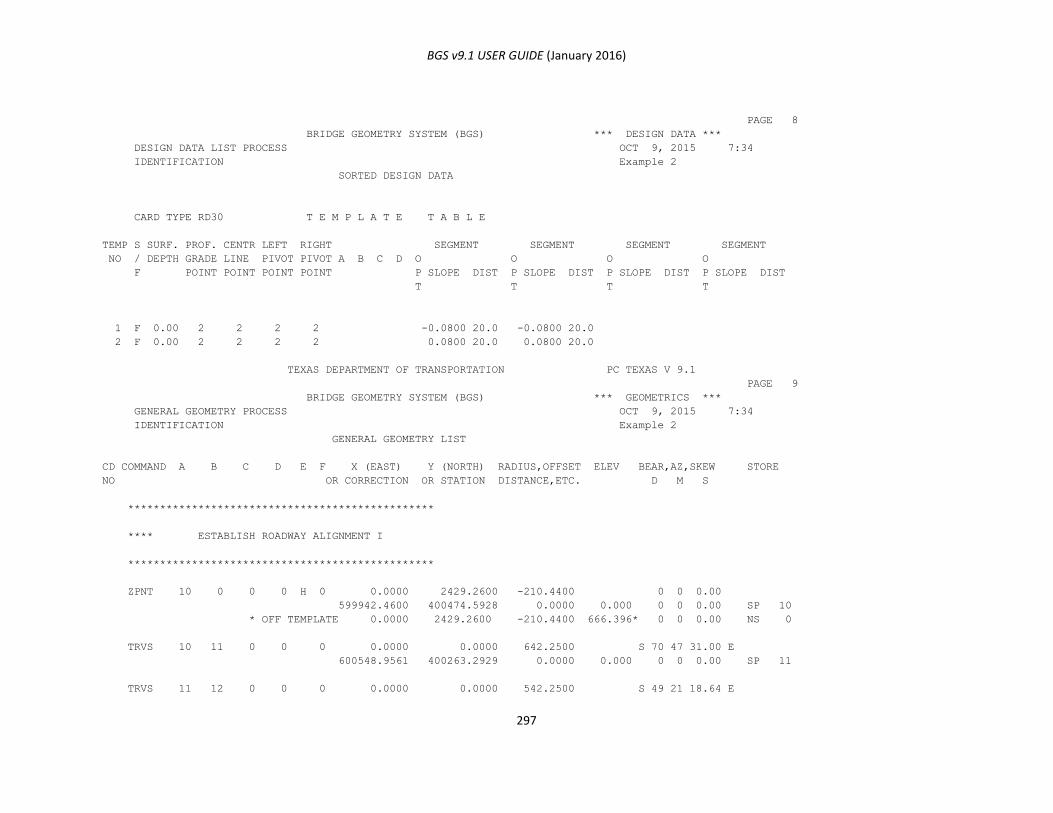
BGS v9.1 USER GUIDE (January 2016)
297
PAGE 8
BRIDGE GEOMETRY SYSTEM (BGS) *** DESIGN DATA ***
DESIGN DATA LIST PROCESS OCT 9, 2015 7:34
IDENTIFICATION Example 2
SORTED DESIGN DATA
CARD TYPE RD30 T E M P L A T E T A B L E
TEMP S SURF. PROF. CENTR LEFT RIGHT SEGMENT SEGMENT SEGMENT SEGMENT
NO / DEPTH GRADE LINE PIVOT PIVOT A B C D O O O O
F POINT POINT POINT POINT P SLOPE DIST P SLOPE DIST P SLOPE DIST P SLOPE DIST
T T T T
1 F 0.00 2 2 2 2 -0.0800 20.0 -0.0800 20.0
2 F 0.00 2 2 2 2 0.0800 20.0 0.0800 20.0
TEXAS DEPARTMENT OF TRANSPORTATION PC TEXAS V 9.1
PAGE 9
BRIDGE GEOMETRY SYSTEM (BGS) *** GEOMETRICS ***
GENERAL GEOMETRY PROCESS OCT 9, 2015 7:34
IDENTIFICATION Example 2
GENERAL GEOMETRY LIST
CD COMMAND A B C D E F X (EAST) Y (NORTH) RADIUS,OFFSET ELEV BEAR,AZ,SKEW STORE
NO OR CORRECTION OR STATION DISTANCE,ETC. D M S
************************************************
**** ESTABLISH ROADWAY ALIGNMENT I
************************************************
ZPNT 10 0 0 0 H 0 0.0000 2429.2600 -210.4400 0 0 0.00
599942.4600 400474.5928 0.0000 0.000 0 0 0.00 SP 10
* OFF TEMPLATE 0.0000 2429.2600 -210.4400 666.396* 0 0 0.00 NS 0
TRVS 10 11 0 0 0 0.0000 0.0000 642.2500 S 70 47 31.00 E
600548.9561 400263.2929 0.0000 0.000 0 0 0.00 SP 11
TRVS 11 12 0 0 0 0.0000 0.0000 542.2500 S 49 21 18.64 E

BGS v9.1 USER GUIDE (January 2016)
298
600960.3947 399910.0886 0.0000 0.000 0 0 0.00 SP 12
TEXAS DEPARTMENT OF TRANSPORTATION PC TEXAS V 9.1
PAGE 10
BRIDGE GEOMETRY SYSTEM (BGS) *** DESIGN DATA ***
DESIGN DATA LIST PROCESS OCT 9, 2015 7:34
IDENTIFICATION Example 2
POINTS STORED OR USED BY ALIGNMENTS
PI 1, ROADWAY I IS DEFINED BY STORED POINT 10 ( X= 599942.4600, Y= 400474.5928)
PI 2, ROADWAY I IS DEFINED BY STORED POINT 11 ( X= 600548.9561, Y= 400263.2929)
PI 3, ROADWAY I IS DEFINED BY STORED POINT 12 ( X= 600960.3947, Y= 399910.0886)
TEXAS DEPARTMENT OF TRANSPORTATION PC TEXAS V 9.1
PAGE 11
BRIDGE GEOMETRY SYSTEM (BGS) *** DESIGN DATA ***
HORIZONTAL ALIGNMENT PROCESS OCT 9, 2015 7:34
IDENTIFICATION Example 2
HORIZONTAL ALIGNMENT LIST
FOR ROADWAY I
COMPUTATIONS BASED ON ARC DEFINITION
P.I. X Y
1 287+55.7800 599942.4600 400474.5928
S 70 47 31.00 E 642.2500 FT.
288+55.7816 PC 2 0 0.15 D 542.2484 T 600036.8946 400441.6923
2 293+98.0300 PI 21 26 12.36 RT 1071.8163 L 600548.9561 400263.2929
299+27.5979 PT 2864.7300 R 600960.3935 399910.0897
S 49 21 18.64 E 542.2500 FT.
3 299+27.5995 600960.3947 399910.0886
TEXAS DEPARTMENT OF TRANSPORTATION PC TEXAS V 9.1
PAGE 12
BRIDGE GEOMETRY SYSTEM (BGS) *** DESIGN DATA ***
DESIGN DATA LIST PROCESS OCT 9, 2015 7:34
IDENTIFICATION Example 2
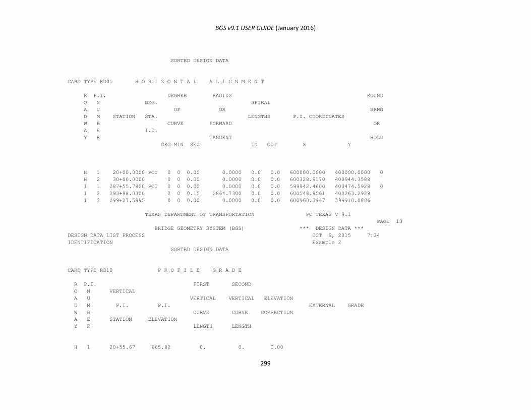
BGS v9.1 USER GUIDE (January 2016)
299
SORTED DESIGN DATA
CARD TYPE RD05 H O R I Z O N T A L A L I G N M E N T
R P.I. DEGREE RADIUS ROUND
O N BEG. SPIRAL
A U OF OR BRNG
D M STATION STA. LENGTHS P.I. COORDINATES
W B CURVE FORWARD OR
A E I.D.
Y R TANGENT HOLD
DEG MIN SEC IN OUT X Y
H 1 20+00.0000 POT 0 0 0.00 0.0000 0.0 0.0 600000.0000 400000.0000 0
H 2 30+00.0000 0 0 0.00 0.0000 0.0 0.0 600328.9170 400944.3588
I 1 287+55.7800 POT 0 0 0.00 0.0000 0.0 0.0 599942.4600 400474.5928 0
I 2 293+98.0300 2 0 0.15 2864.7300 0.0 0.0 600548.9561 400263.2929
I 3 299+27.5995 0 0 0.00 0.0000 0.0 0.0 600960.3947 399910.0886
TEXAS DEPARTMENT OF TRANSPORTATION PC TEXAS V 9.1
PAGE 13
BRIDGE GEOMETRY SYSTEM (BGS) *** DESIGN DATA ***
DESIGN DATA LIST PROCESS OCT 9, 2015 7:34
IDENTIFICATION Example 2
SORTED DESIGN DATA
CARD TYPE RD10 P R O F I L E G R A D E
R P.I. FIRST SECOND
O N VERTICAL
A U VERTICAL VERTICAL ELEVATION
D M P.I. P.I. EXTERNAL GRADE
W B CURVE CURVE CORRECTION
A E STATION ELEVATION
Y R LENGTH LENGTH
H 1 20+55.67 665.82 0. 0. 0.00

BGS v9.1 USER GUIDE (January 2016)
300
H 2 28+47.13 670.43 0. 0. 0.00 0.005825
I 1 288+55.78 642.82 0. 0. 0.00
I 2 299+27.62 642.82 0. 0. 0.00 0.000000
TEXAS DEPARTMENT OF TRANSPORTATION PC TEXAS V 9.1
PAGE 14
BRIDGE GEOMETRY SYSTEM (BGS) *** DESIGN DATA ***
DESIGN DATA LIST PROCESS OCT 9, 2015 7:34
IDENTIFICATION Example 2
SORTED DESIGN DATA
CARD TYPE RD30 T E M P L A T E
R
O TEMPLATE
A
D STATION STORE/
W RECALL
A
Y NO.
H 21+10.00 1
H 21+32.50 1
H 21+77.50 2
H 28+47.13 2
I 288+55.78 3
I 299+27.62 3
TEXAS DEPARTMENT OF TRANSPORTATION PC TEXAS V 9.1
PAGE 15
BRIDGE GEOMETRY SYSTEM (BGS) *** DESIGN DATA ***
DESIGN DATA LIST PROCESS OCT 9, 2015 7:34
IDENTIFICATION Example 2
SORTED DESIGN DATA
CARD TYPE RD30 T E M P L A T E T A B L E
TEMP S SURF. PROF. CENTR LEFT RIGHT SEGMENT SEGMENT SEGMENT SEGMENT
NO / DEPTH GRADE LINE PIVOT PIVOT A B C D O O O O
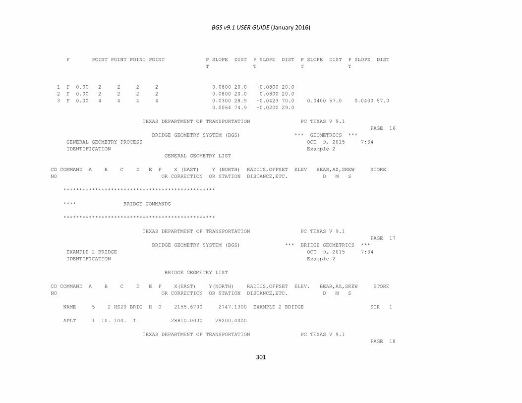
BGS v9.1 USER GUIDE (January 2016)
301
F POINT POINT POINT POINT P SLOPE DIST P SLOPE DIST P SLOPE DIST P SLOPE DIST
T T T T
1 F 0.00 2 2 2 2 -0.0800 20.0 -0.0800 20.0
2 F 0.00 2 2 2 2 0.0800 20.0 0.0800 20.0
3 F 0.00 4 4 4 4 0.0300 28.9 -0.0423 70.0 0.0400 57.0 0.0400 57.0
0.0064 74.9 -0.0200 29.0
TEXAS DEPARTMENT OF TRANSPORTATION PC TEXAS V 9.1
PAGE 16
BRIDGE GEOMETRY SYSTEM (BGS) *** GEOMETRICS ***
GENERAL GEOMETRY PROCESS OCT 9, 2015 7:34
IDENTIFICATION Example 2
GENERAL GEOMETRY LIST
CD COMMAND A B C D E F X (EAST) Y (NORTH) RADIUS,OFFSET ELEV BEAR,AZ,SKEW STORE
NO OR CORRECTION OR STATION DISTANCE,ETC. D M S
************************************************
**** BRIDGE COMMANDS
************************************************
TEXAS DEPARTMENT OF TRANSPORTATION PC TEXAS V 9.1
PAGE 17
BRIDGE GEOMETRY SYSTEM (BGS) *** BRIDGE GEOMETRICS ***
EXAMPLE 2 BRIDGE OCT 9, 2015 7:34
IDENTIFICATION Example 2
BRIDGE GEOMETRY LIST
CD COMMAND A B C D E F X(EAST) Y(NORTH) RADIUS,OFFSET ELEV. BEAR,AZ,SKEW STORE
NO OR CORRECTION OR STATION DISTANCE,ETC. D M S
NAME 5 2 HS20 BRIG H 0 2155.6700 2747.1300 EXAMPLE 2 BRIDGE STR 1
APLT 1 10. 100. I 28810.0000 29200.0000
TEXAS DEPARTMENT OF TRANSPORTATION PC TEXAS V 9.1
PAGE 18

BGS v9.1 USER GUIDE (January 2016)
302
BRIDGE GEOMETRY SYSTEM (BGS) *** GEOMETRICS ***
ALIGNMENT PLOT PROCESS OCT 9, 2015 7:34
IDENTIFICATION Example 2
* * * ALIGNMENT PLOT DATA FOR ROADWAY I * * *
ALIGNMENT ELEMENT BEGINNING EAST (X) NORTH (Y) BEARING RADIUS,
ELEMENT TYPE STATION BEGINNING BEGINNING SPIRAL LENGTH,
NUMBER OR STA. BACK STA. FORWARD
1 LINE 288+10.00 599993.6616 400456.7544 S 70 47 31.00 E
2 ARC 288+55.78 600036.8946 400441.6923 S 70 47 31.00 E 2864.73
3 END STA 292+00.00 600354.3732 400309.2115 S 63 54 26.77 E
* * * TABLE OF CENTERS FOR ALIGNMENT ELEMENTS AND OFFSETS * * *
ALIGNMENT OFFSET PARALLEL TO EAST (X) NORTH (Y)
ELEMENT LINE ALIGNMENT
NUMBER NUMBER ELEMENT NO.
2 599094.4001 397736.4415
* * * CURVE FIT DATA FOR ALL ALIGNMENT ELEMENTS AND OFFSETS * * *
POINT STATION EAST (X) NORTH (Y) --------- S O U R C E ---------
ALIGNMENT OFFSET INTERIOR
ELEMENT LINE POINT
1 288+10.00 599993.6616 400456.7544 1
2 288+55.78 600036.8946 400441.6923 2
3 290+27.89 600197.6243 400380.2218 2 *
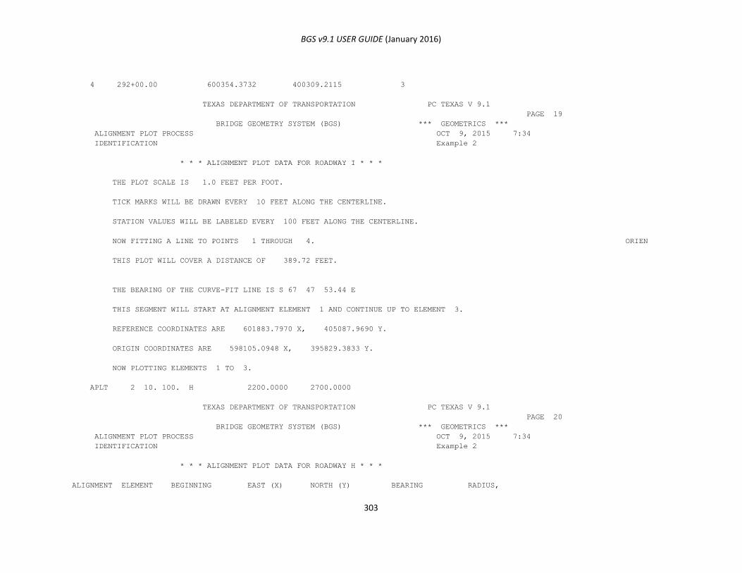
BGS v9.1 USER GUIDE (January 2016)
303
4 292+00.00 600354.3732 400309.2115 3
TEXAS DEPARTMENT OF TRANSPORTATION PC TEXAS V 9.1
PAGE 19
BRIDGE GEOMETRY SYSTEM (BGS) *** GEOMETRICS ***
ALIGNMENT PLOT PROCESS OCT 9, 2015 7:34
IDENTIFICATION Example 2
* * * ALIGNMENT PLOT DATA FOR ROADWAY I * * *
THE PLOT SCALE IS 1.0 FEET PER FOOT.
TICK MARKS WILL BE DRAWN EVERY 10 FEET ALONG THE CENTERLINE.
STATION VALUES WILL BE LABELED EVERY 100 FEET ALONG THE CENTERLINE.
NOW FITTING A LINE TO POINTS 1 THROUGH 4. ORIEN
THIS PLOT WILL COVER A DISTANCE OF 389.72 FEET.
THE BEARING OF THE CURVE-FIT LINE IS S 67 47 53.44 E
THIS SEGMENT WILL START AT ALIGNMENT ELEMENT 1 AND CONTINUE UP TO ELEMENT 3.
REFERENCE COORDINATES ARE 601883.7970 X, 405087.9690 Y.
ORIGIN COORDINATES ARE 598105.0948 X, 395829.3833 Y.
NOW PLOTTING ELEMENTS 1 TO 3.
APLT 2 10. 100. H 2200.0000 2700.0000
TEXAS DEPARTMENT OF TRANSPORTATION PC TEXAS V 9.1
PAGE 20
BRIDGE GEOMETRY SYSTEM (BGS) *** GEOMETRICS ***
ALIGNMENT PLOT PROCESS OCT 9, 2015 7:34
IDENTIFICATION Example 2
* * * ALIGNMENT PLOT DATA FOR ROADWAY H * * *
ALIGNMENT ELEMENT BEGINNING EAST (X) NORTH (Y) BEARING RADIUS,
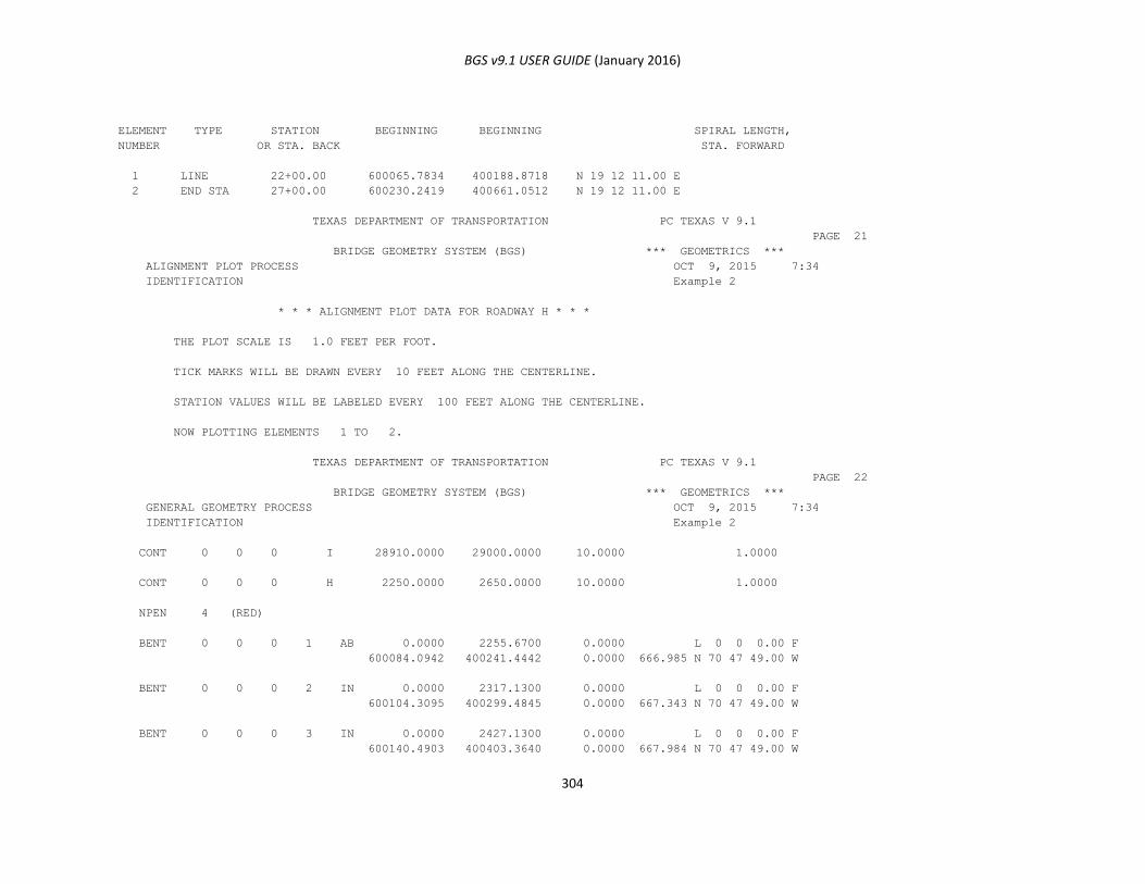
BGS v9.1 USER GUIDE (January 2016)
304
ELEMENT TYPE STATION BEGINNING BEGINNING SPIRAL LENGTH,
NUMBER OR STA. BACK STA. FORWARD
1 LINE 22+00.00 600065.7834 400188.8718 N 19 12 11.00 E
2 END STA 27+00.00 600230.2419 400661.0512 N 19 12 11.00 E
TEXAS DEPARTMENT OF TRANSPORTATION PC TEXAS V 9.1
PAGE 21
BRIDGE GEOMETRY SYSTEM (BGS) *** GEOMETRICS ***
ALIGNMENT PLOT PROCESS OCT 9, 2015 7:34
IDENTIFICATION Example 2
* * * ALIGNMENT PLOT DATA FOR ROADWAY H * * *
THE PLOT SCALE IS 1.0 FEET PER FOOT.
TICK MARKS WILL BE DRAWN EVERY 10 FEET ALONG THE CENTERLINE.
STATION VALUES WILL BE LABELED EVERY 100 FEET ALONG THE CENTERLINE.
NOW PLOTTING ELEMENTS 1 TO 2.
TEXAS DEPARTMENT OF TRANSPORTATION PC TEXAS V 9.1
PAGE 22
BRIDGE GEOMETRY SYSTEM (BGS) *** GEOMETRICS ***
GENERAL GEOMETRY PROCESS OCT 9, 2015 7:34
IDENTIFICATION Example 2
CONT 0 0 0 I 28910.0000 29000.0000 10.0000 1.0000
CONT 0 0 0 H 2250.0000 2650.0000 10.0000 1.0000
NPEN 4 (RED)
BENT 0 0 0 1 AB 0.0000 2255.6700 0.0000 L 0 0 0.00 F
600084.0942 400241.4442 0.0000 666.985 N 70 47 49.00 W
BENT 0 0 0 2 IN 0.0000 2317.1300 0.0000 L 0 0 0.00 F
600104.3095 400299.4845 0.0000 667.343 N 70 47 49.00 W
BENT 0 0 0 3 IN 0.0000 2427.1300 0.0000 L 0 0 0.00 F
600140.4903 400403.3640 0.0000 667.984 N 70 47 49.00 W
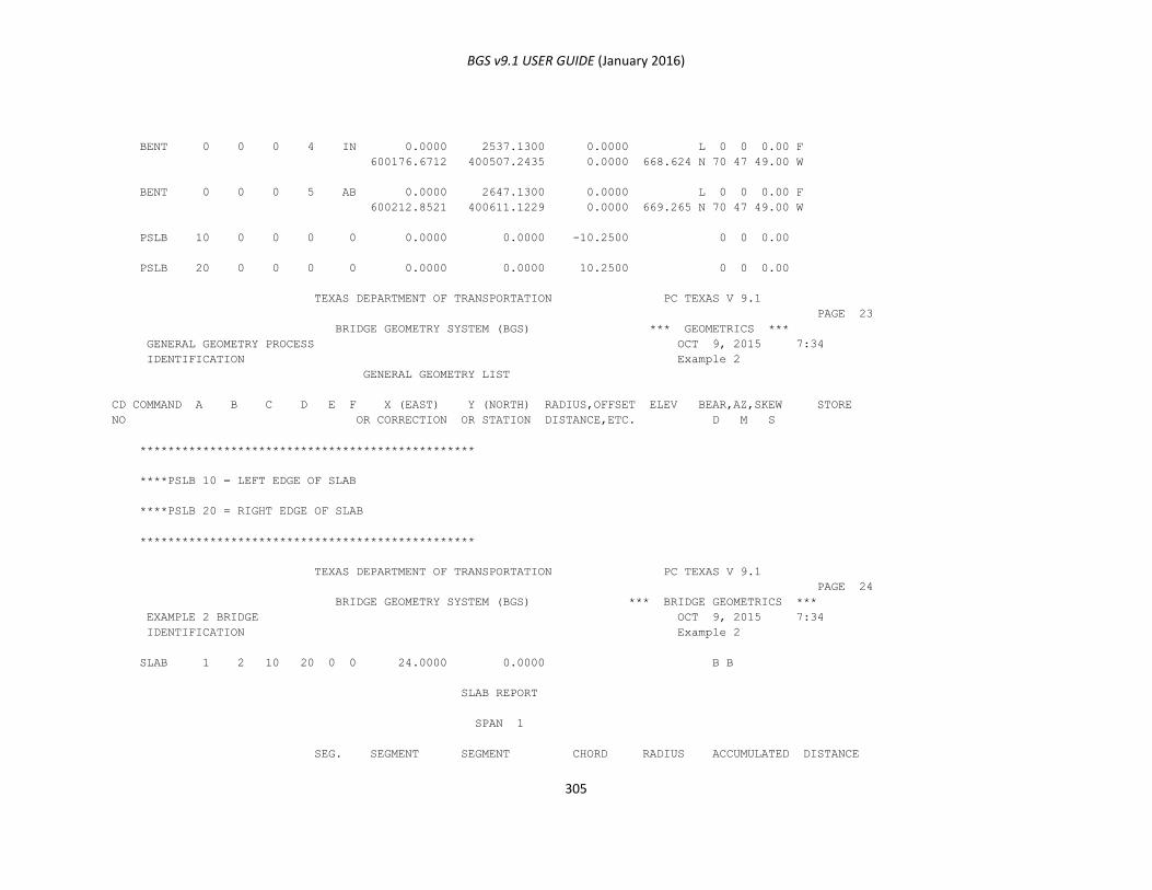
BGS v9.1 USER GUIDE (January 2016)
305
BENT 0 0 0 4 IN 0.0000 2537.1300 0.0000 L 0 0 0.00 F
600176.6712 400507.2435 0.0000 668.624 N 70 47 49.00 W
BENT 0 0 0 5 AB 0.0000 2647.1300 0.0000 L 0 0 0.00 F
600212.8521 400611.1229 0.0000 669.265 N 70 47 49.00 W
PSLB 10 0 0 0 0 0.0000 0.0000 -10.2500 0 0 0.00
PSLB 20 0 0 0 0 0.0000 0.0000 10.2500 0 0 0.00
TEXAS DEPARTMENT OF TRANSPORTATION PC TEXAS V 9.1
PAGE 23
BRIDGE GEOMETRY SYSTEM (BGS) *** GEOMETRICS ***
GENERAL GEOMETRY PROCESS OCT 9, 2015 7:34
IDENTIFICATION Example 2
GENERAL GEOMETRY LIST
CD COMMAND A B C D E F X (EAST) Y (NORTH) RADIUS,OFFSET ELEV BEAR,AZ,SKEW STORE
NO OR CORRECTION OR STATION DISTANCE,ETC. D M S
************************************************
****PSLB 10 = LEFT EDGE OF SLAB
****PSLB 20 = RIGHT EDGE OF SLAB
************************************************
TEXAS DEPARTMENT OF TRANSPORTATION PC TEXAS V 9.1
PAGE 24
BRIDGE GEOMETRY SYSTEM (BGS) *** BRIDGE GEOMETRICS ***
EXAMPLE 2 BRIDGE OCT 9, 2015 7:34
IDENTIFICATION Example 2
SLAB 1 2 10 20 0 0 24.0000 0.0000 B B
SLAB REPORT
SPAN 1
SEG. SEGMENT SEGMENT CHORD RADIUS ACCUMULATED DISTANCE
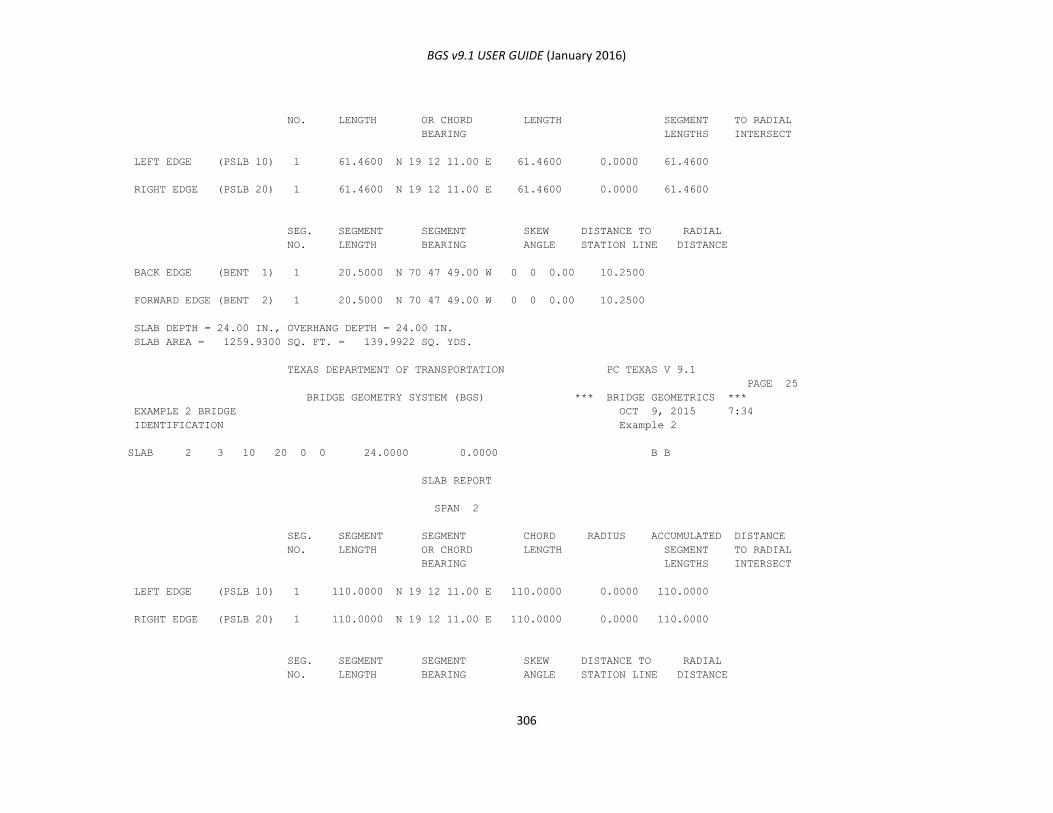
BGS v9.1 USER GUIDE (January 2016)
306
NO. LENGTH OR CHORD LENGTH SEGMENT TO RADIAL
BEARING LENGTHS INTERSECT
LEFT EDGE (PSLB 10) 1 61.4600 N 19 12 11.00 E 61.4600 0.0000 61.4600
RIGHT EDGE (PSLB 20) 1 61.4600 N 19 12 11.00 E 61.4600 0.0000 61.4600
SEG. SEGMENT SEGMENT SKEW DISTANCE TO RADIAL
NO. LENGTH BEARING ANGLE STATION LINE DISTANCE
BACK EDGE (BENT 1) 1 20.5000 N 70 47 49.00 W 0 0 0.00 10.2500
FORWARD EDGE (BENT 2) 1 20.5000 N 70 47 49.00 W 0 0 0.00 10.2500
SLAB DEPTH = 24.00 IN., OVERHANG DEPTH = 24.00 IN.
SLAB AREA = 1259.9300 SQ. FT. = 139.9922 SQ. YDS.
TEXAS DEPARTMENT OF TRANSPORTATION PC TEXAS V 9.1
PAGE 25
BRIDGE GEOMETRY SYSTEM (BGS) *** BRIDGE GEOMETRICS ***
EXAMPLE 2 BRIDGE OCT 9, 2015 7:34
IDENTIFICATION Example 2
SLAB 2 3 10 20 0 0 24.0000 0.0000 B B
SLAB REPORT
SPAN 2
SEG. SEGMENT SEGMENT CHORD RADIUS ACCUMULATED DISTANCE
NO. LENGTH OR CHORD LENGTH SEGMENT TO RADIAL
BEARING LENGTHS INTERSECT
LEFT EDGE (PSLB 10) 1 110.0000 N 19 12 11.00 E 110.0000 0.0000 110.0000
RIGHT EDGE (PSLB 20) 1 110.0000 N 19 12 11.00 E 110.0000 0.0000 110.0000
SEG. SEGMENT SEGMENT SKEW DISTANCE TO RADIAL
NO. LENGTH BEARING ANGLE STATION LINE DISTANCE
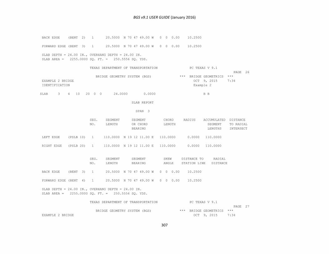
BGS v9.1 USER GUIDE (January 2016)
307
BACK EDGE (BENT 2) 1 20.5000 N 70 47 49.00 W 0 0 0.00 10.2500
FORWARD EDGE (BENT 3) 1 20.5000 N 70 47 49.00 W 0 0 0.00 10.2500
SLAB DEPTH = 24.00 IN., OVERHANG DEPTH = 24.00 IN.
SLAB AREA = 2255.0000 SQ. FT. = 250.5556 SQ. YDS.
TEXAS DEPARTMENT OF TRANSPORTATION PC TEXAS V 9.1
PAGE 26
BRIDGE GEOMETRY SYSTEM (BGS) *** BRIDGE GEOMETRICS ***
EXAMPLE 2 BRIDGE OCT 9, 2015 7:34
IDENTIFICATION Example 2
SLAB 3 4 10 20 0 0 24.0000 0.0000 B B
SLAB REPORT
SPAN 3
SEG. SEGMENT SEGMENT CHORD RADIUS ACCUMULATED DISTANCE
NO. LENGTH OR CHORD LENGTH SEGMENT TO RADIAL
BEARING LENGTHS INTERSECT
LEFT EDGE (PSLB 10) 1 110.0000 N 19 12 11.00 E 110.0000 0.0000 110.0000
RIGHT EDGE (PSLB 20) 1 110.0000 N 19 12 11.00 E 110.0000 0.0000 110.0000
SEG. SEGMENT SEGMENT SKEW DISTANCE TO RADIAL
NO. LENGTH BEARING ANGLE STATION LINE DISTANCE
BACK EDGE (BENT 3) 1 20.5000 N 70 47 49.00 W 0 0 0.00 10.2500
FORWARD EDGE (BENT 4) 1 20.5000 N 70 47 49.00 W 0 0 0.00 10.2500
SLAB DEPTH = 24.00 IN., OVERHANG DEPTH = 24.00 IN.
SLAB AREA = 2255.0000 SQ. FT. = 250.5556 SQ. YDS.
TEXAS DEPARTMENT OF TRANSPORTATION PC TEXAS V 9.1
PAGE 27
BRIDGE GEOMETRY SYSTEM (BGS) *** BRIDGE GEOMETRICS ***
EXAMPLE 2 BRIDGE OCT 9, 2015 7:34
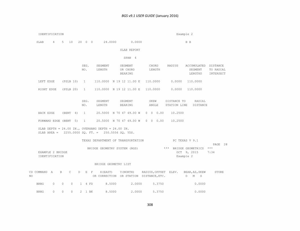
BGS v9.1 USER GUIDE (January 2016)
308
IDENTIFICATION Example 2
SLAB 4 5 10 20 0 0 24.0000 0.0000 B B
SLAB REPORT
SPAN 4
SEG. SEGMENT SEGMENT CHORD RADIUS ACCUMULATED DISTANCE
NO. LENGTH OR CHORD LENGTH SEGMENT TO RADIAL
BEARING LENGTHS INTERSECT
LEFT EDGE (PSLB 10) 1 110.0000 N 19 12 11.00 E 110.0000 0.0000 110.0000
RIGHT EDGE (PSLB 20) 1 110.0000 N 19 12 11.00 E 110.0000 0.0000 110.0000
SEG. SEGMENT SEGMENT SKEW DISTANCE TO RADIAL
NO. LENGTH BEARING ANGLE STATION LINE DISTANCE
BACK EDGE (BENT 4) 1 20.5000 N 70 47 49.00 W 0 0 0.00 10.2500
FORWARD EDGE (BENT 5) 1 20.5000 N 70 47 49.00 W 0 0 0.00 10.2500
SLAB DEPTH = 24.00 IN., OVERHANG DEPTH = 24.00 IN.
SLAB AREA = 2255.0000 SQ. FT. = 250.5556 SQ. YDS.
TEXAS DEPARTMENT OF TRANSPORTATION PC TEXAS V 9.1
PAGE 28
BRIDGE GEOMETRY SYSTEM (BGS) *** BRIDGE GEOMETRICS ***
EXAMPLE 2 BRIDGE OCT 9, 2015 7:34
IDENTIFICATION Example 2
BRIDGE GEOMETRY LIST
CD COMMAND A B C D E F X(EAST) Y(NORTH) RADIUS,OFFSET ELEV. BEAR,AZ,SKEW STORE
NO OR CORRECTION OR STATION DISTANCE,ETC. D M S
BRNG 0 0 0 1 4 FD 8.5000 2.0000 5.3750 0.0000
BRNG 0 0 0 2 1 BK 8.5000 2.0000 5.3750 0.0000
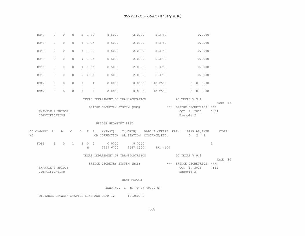
BGS v9.1 USER GUIDE (January 2016)
309
BRNG 0 0 0 2 1 FD 8.5000 2.0000 5.3750 0.0000
BRNG 0 0 0 3 1 BK 8.5000 2.0000 5.3750 0.0000
BRNG 0 0 0 3 1 FD 8.5000 2.0000 5.3750 0.0000
BRNG 0 0 0 4 1 BK 8.5000 2.0000 5.3750 0.0000
BRNG 0 0 0 4 1 FD 8.5000 2.0000 5.3750 0.0000
BRNG 0 0 0 5 4 BK 8.5000 2.0000 5.3750 0.0000
BEAM 0 0 0 0 1 0.0000 0.0000 -10.2500 0 0 0.00
BEAM 0 0 0 0 2 0.0000 0.0000 10.2500 0 0 0.00
TEXAS DEPARTMENT OF TRANSPORTATION PC TEXAS V 9.1
PAGE 29
BRIDGE GEOMETRY SYSTEM (BGS) *** BRIDGE GEOMETRICS ***
EXAMPLE 2 BRIDGE OCT 9, 2015 7:34
IDENTIFICATION Example 2
BRIDGE GEOMETRY LIST
CD COMMAND A B C D E F X(EAST) Y(NORTH) RADIUS,OFFSET ELEV. BEAR,AZ,SKEW STORE
NO OR CORRECTION OR STATION DISTANCE,ETC. D M S
FOPT 1 5 1 2 5 6 0.0000 0.0000 1
H 2255.6700 2647.1300 391.4600
TEXAS DEPARTMENT OF TRANSPORTATION PC TEXAS V 9.1
PAGE 30
BRIDGE GEOMETRY SYSTEM (BGS) *** BRIDGE GEOMETRICS ***
EXAMPLE 2 BRIDGE OCT 9, 2015 7:34
IDENTIFICATION Example 2
BENT REPORT
BENT NO. 1 (N 70 47 49.00 W)
DISTANCE BETWEEN STATION LINE AND BEAM 1, 10.2500 L
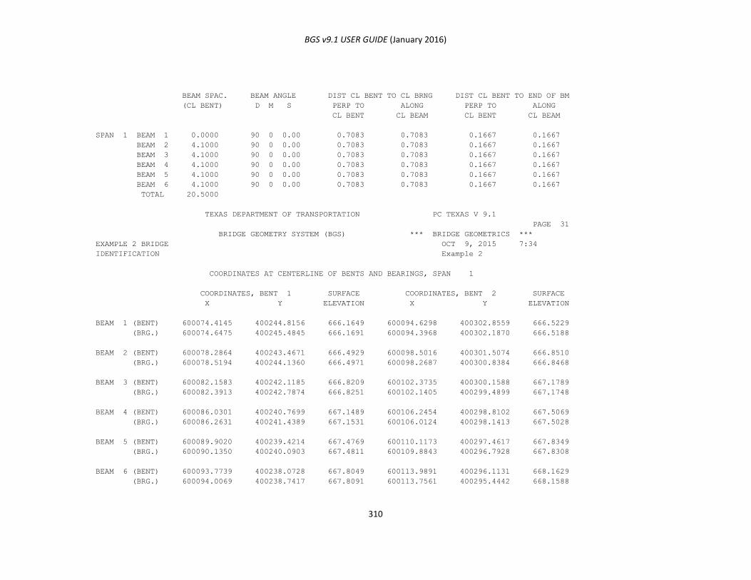
BGS v9.1 USER GUIDE (January 2016)
310
BEAM SPAC. BEAM ANGLE DIST CL BENT TO CL BRNG DIST CL BENT TO END OF BM
(CL BENT) D M S PERP TO ALONG PERP TO ALONG
CL BENT CL BEAM CL BENT CL BEAM
SPAN 1 BEAM 1 0.0000 90 0 0.00 0.7083 0.7083 0.1667 0.1667
BEAM 2 4.1000 90 0 0.00 0.7083 0.7083 0.1667 0.1667
BEAM 3 4.1000 90 0 0.00 0.7083 0.7083 0.1667 0.1667
BEAM 4 4.1000 90 0 0.00 0.7083 0.7083 0.1667 0.1667
BEAM 5 4.1000 90 0 0.00 0.7083 0.7083 0.1667 0.1667
BEAM 6 4.1000 90 0 0.00 0.7083 0.7083 0.1667 0.1667
TOTAL 20.5000
TEXAS DEPARTMENT OF TRANSPORTATION PC TEXAS V 9.1
PAGE 31
BRIDGE GEOMETRY SYSTEM (BGS) *** BRIDGE GEOMETRICS ***
EXAMPLE 2 BRIDGE OCT 9, 2015 7:34
IDENTIFICATION Example 2
COORDINATES AT CENTERLINE OF BENTS AND BEARINGS, SPAN 1
COORDINATES, BENT 1 SURFACE COORDINATES, BENT 2 SURFACE
X Y ELEVATION X Y ELEVATION
BEAM 1 (BENT) 600074.4145 400244.8156 666.1649 600094.6298 400302.8559 666.5229
(BRG.) 600074.6475 400245.4845 666.1691 600094.3968 400302.1870 666.5188
BEAM 2 (BENT) 600078.2864 400243.4671 666.4929 600098.5016 400301.5074 666.8510
(BRG.) 600078.5194 400244.1360 666.4971 600098.2687 400300.8384 666.8468
BEAM 3 (BENT) 600082.1583 400242.1185 666.8209 600102.3735 400300.1588 667.1789
(BRG.) 600082.3913 400242.7874 666.8251 600102.1405 400299.4899 667.1748
BEAM 4 (BENT) 600086.0301 400240.7699 667.1489 600106.2454 400298.8102 667.5069
(BRG.) 600086.2631 400241.4389 667.1531 600106.0124 400298.1413 667.5028
BEAM 5 (BENT) 600089.9020 400239.4214 667.4769 600110.1173 400297.4617 667.8349
(BRG.) 600090.1350 400240.0903 667.4811 600109.8843 400296.7928 667.8308
BEAM 6 (BENT) 600093.7739 400238.0728 667.8049 600113.9891 400296.1131 668.1629
(BRG.) 600094.0069 400238.7417 667.8091 600113.7561 400295.4442 668.1588
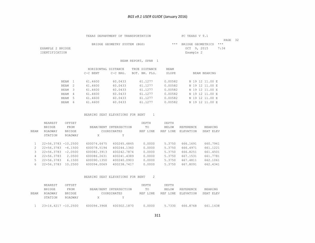
BGS v9.1 USER GUIDE (January 2016)
311
TEXAS DEPARTMENT OF TRANSPORTATION PC TEXAS V 9.1
PAGE 32
BRIDGE GEOMETRY SYSTEM (BGS) *** BRIDGE GEOMETRICS ***
EXAMPLE 2 BRIDGE OCT 9, 2015 7:34
IDENTIFICATION Example 2
BEAM REPORT, SPAN 1
HORIZONTAL DISTANCE TRUE DISTANCE BEAM
C-C BENT C-C BRG. BOT. BM. FLG. SLOPE BEAM BEARING
BEAM 1 61.4600 60.0433 61.1277 0.00582 N 19 12 11.00 E
BEAM 2 61.4600 60.0433 61.1277 0.00582 N 19 12 11.00 E
BEAM 3 61.4600 60.0433 61.1277 0.00582 N 19 12 11.00 E
BEAM 4 61.4600 60.0433 61.1277 0.00582 N 19 12 11.00 E
BEAM 5 61.4600 60.0433 61.1277 0.00582 N 19 12 11.00 E
BEAM 6 61.4600 60.0433 61.1277 0.00582 N 19 12 11.00 E
BEARING SEAT ELEVATIONS FOR BENT 1
NEAREST OFFSET DEPTH DEPTH
BRIDGE FROM BEAM/BENT INTERSECTION TO BELOW REFERENCE BEARING
BEAM ROADWAY BRIDGE COORDINATES REF LINE REF LINE ELEVATION SEAT ELEV
STATION ROADWAY X Y
1 22+56.3783 -10.2500 600074.6475 400245.4845 0.0000 5.3750 666.1691 660.7941
2 22+56.3783 -6.1500 600078.5194 400244.1360 0.0000 5.3750 666.4971 661.1221
3 22+56.3783 -2.0500 600082.3913 400242.7874 0.0000 5.3750 666.8251 661.4501
4 22+56.3783 2.0500 600086.2631 400241.4389 0.0000 5.3750 667.1531 661.7781
5 22+56.3783 6.1500 600090.1350 400240.0903 0.0000 5.3750 667.4811 662.1061
6 22+56.3783 10.2500 600094.0069 400238.7417 0.0000 5.3750 667.8091 662.4341
BEARING SEAT ELEVATIONS FOR BENT 2
NEAREST OFFSET DEPTH DEPTH
BRIDGE FROM BEAM/BENT INTERSECTION TO BELOW REFERENCE BEARING
BEAM ROADWAY BRIDGE COORDINATES REF LINE REF LINE ELEVATION SEAT ELEV
STATION ROADWAY X Y
1 23+16.4217 -10.2500 600094.3968 400302.1870 0.0000 5.7330 666.8768 661.1438
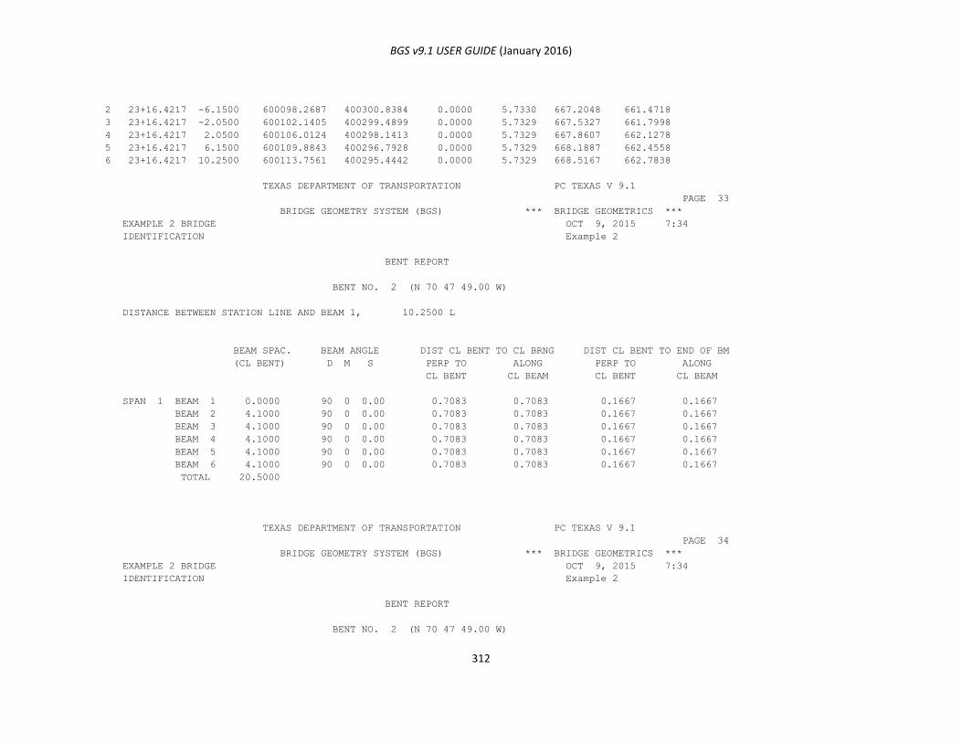
BGS v9.1 USER GUIDE (January 2016)
312
2 23+16.4217 -6.1500 600098.2687 400300.8384 0.0000 5.7330 667.2048 661.4718
3 23+16.4217 -2.0500 600102.1405 400299.4899 0.0000 5.7329 667.5327 661.7998
4 23+16.4217 2.0500 600106.0124 400298.1413 0.0000 5.7329 667.8607 662.1278
5 23+16.4217 6.1500 600109.8843 400296.7928 0.0000 5.7329 668.1887 662.4558
6 23+16.4217 10.2500 600113.7561 400295.4442 0.0000 5.7329 668.5167 662.7838
TEXAS DEPARTMENT OF TRANSPORTATION PC TEXAS V 9.1
PAGE 33
BRIDGE GEOMETRY SYSTEM (BGS) *** BRIDGE GEOMETRICS ***
EXAMPLE 2 BRIDGE OCT 9, 2015 7:34
IDENTIFICATION Example 2
BENT REPORT
BENT NO. 2 (N 70 47 49.00 W)
DISTANCE BETWEEN STATION LINE AND BEAM 1, 10.2500 L
BEAM SPAC. BEAM ANGLE DIST CL BENT TO CL BRNG DIST CL BENT TO END OF BM
(CL BENT) D M S PERP TO ALONG PERP TO ALONG
CL BENT CL BEAM CL BENT CL BEAM
SPAN 1 BEAM 1 0.0000 90 0 0.00 0.7083 0.7083 0.1667 0.1667
BEAM 2 4.1000 90 0 0.00 0.7083 0.7083 0.1667 0.1667
BEAM 3 4.1000 90 0 0.00 0.7083 0.7083 0.1667 0.1667
BEAM 4 4.1000 90 0 0.00 0.7083 0.7083 0.1667 0.1667
BEAM 5 4.1000 90 0 0.00 0.7083 0.7083 0.1667 0.1667
BEAM 6 4.1000 90 0 0.00 0.7083 0.7083 0.1667 0.1667
TOTAL 20.5000
TEXAS DEPARTMENT OF TRANSPORTATION PC TEXAS V 9.1
PAGE 34
BRIDGE GEOMETRY SYSTEM (BGS) *** BRIDGE GEOMETRICS ***
EXAMPLE 2 BRIDGE OCT 9, 2015 7:34
IDENTIFICATION Example 2
BENT REPORT
BENT NO. 2 (N 70 47 49.00 W)
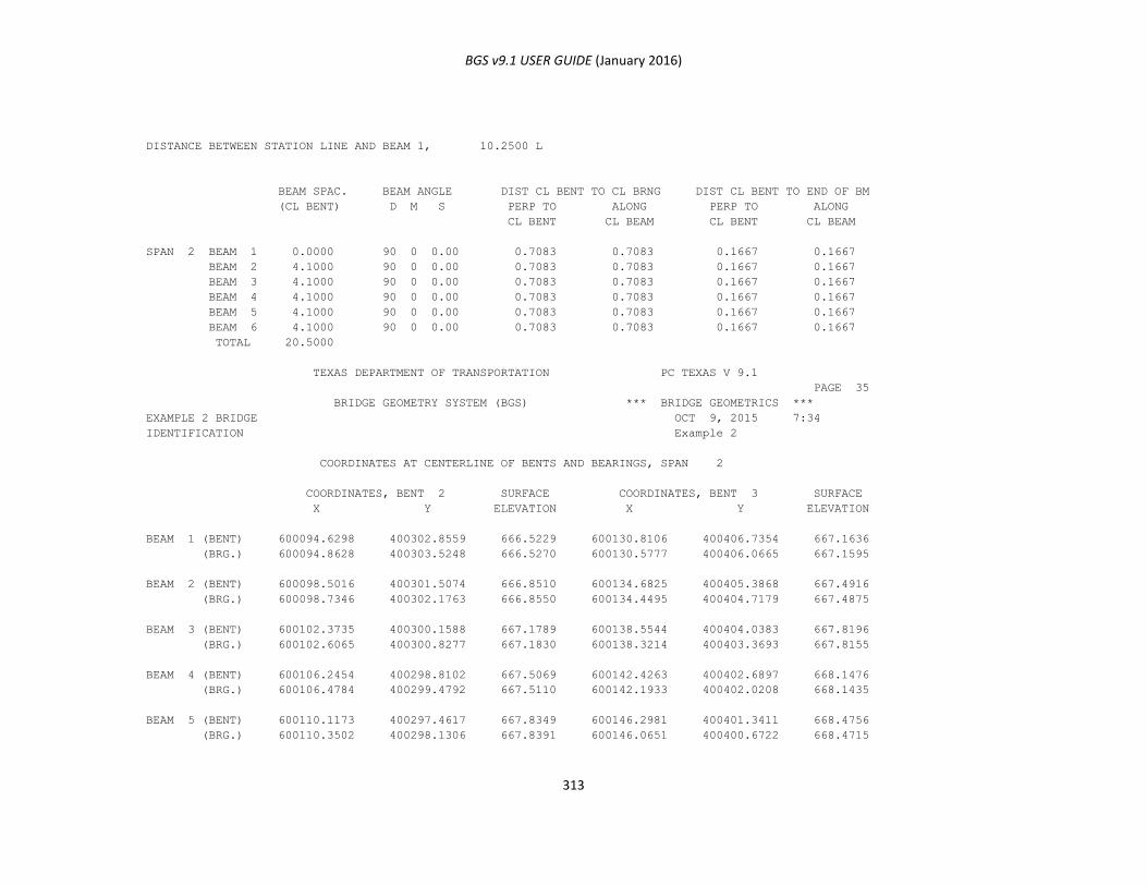
BGS v9.1 USER GUIDE (January 2016)
313
DISTANCE BETWEEN STATION LINE AND BEAM 1, 10.2500 L
BEAM SPAC. BEAM ANGLE DIST CL BENT TO CL BRNG DIST CL BENT TO END OF BM
(CL BENT) D M S PERP TO ALONG PERP TO ALONG
CL BENT CL BEAM CL BENT CL BEAM
SPAN 2 BEAM 1 0.0000 90 0 0.00 0.7083 0.7083 0.1667 0.1667
BEAM 2 4.1000 90 0 0.00 0.7083 0.7083 0.1667 0.1667
BEAM 3 4.1000 90 0 0.00 0.7083 0.7083 0.1667 0.1667
BEAM 4 4.1000 90 0 0.00 0.7083 0.7083 0.1667 0.1667
BEAM 5 4.1000 90 0 0.00 0.7083 0.7083 0.1667 0.1667
BEAM 6 4.1000 90 0 0.00 0.7083 0.7083 0.1667 0.1667
TOTAL 20.5000
TEXAS DEPARTMENT OF TRANSPORTATION PC TEXAS V 9.1
PAGE 35
BRIDGE GEOMETRY SYSTEM (BGS) *** BRIDGE GEOMETRICS ***
EXAMPLE 2 BRIDGE OCT 9, 2015 7:34
IDENTIFICATION Example 2
COORDINATES AT CENTERLINE OF BENTS AND BEARINGS, SPAN 2
COORDINATES, BENT 2 SURFACE COORDINATES, BENT 3 SURFACE
X Y ELEVATION X Y ELEVATION
BEAM 1 (BENT) 600094.6298 400302.8559 666.5229 600130.8106 400406.7354 667.1636
(BRG.) 600094.8628 400303.5248 666.5270 600130.5777 400406.0665 667.1595
BEAM 2 (BENT) 600098.5016 400301.5074 666.8510 600134.6825 400405.3868 667.4916
(BRG.) 600098.7346 400302.1763 666.8550 600134.4495 400404.7179 667.4875
BEAM 3 (BENT) 600102.3735 400300.1588 667.1789 600138.5544 400404.0383 667.8196
(BRG.) 600102.6065 400300.8277 667.1830 600138.3214 400403.3693 667.8155
BEAM 4 (BENT) 600106.2454 400298.8102 667.5069 600142.4263 400402.6897 668.1476
(BRG.) 600106.4784 400299.4792 667.5110 600142.1933 400402.0208 668.1435
BEAM 5 (BENT) 600110.1173 400297.4617 667.8349 600146.2981 400401.3411 668.4756
(BRG.) 600110.3502 400298.1306 667.8391 600146.0651 400400.6722 668.4715
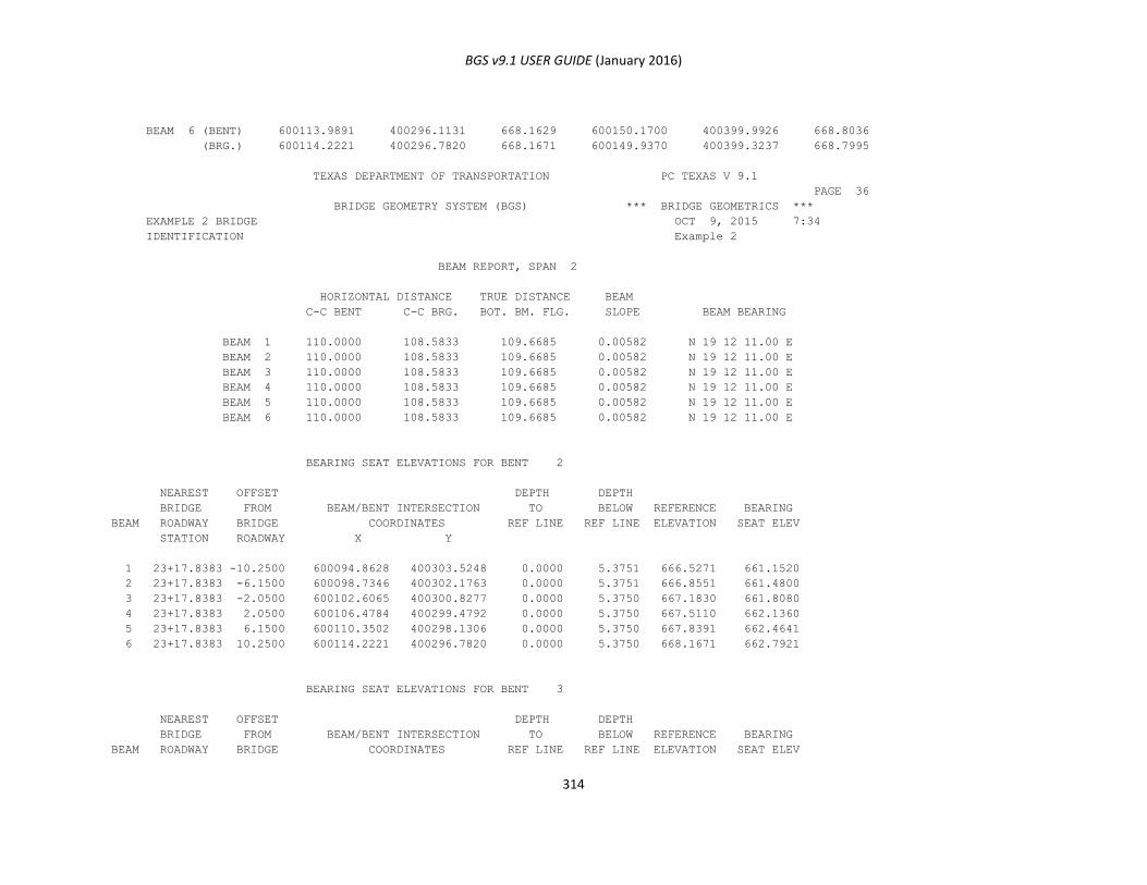
BGS v9.1 USER GUIDE (January 2016)
314
BEAM 6 (BENT) 600113.9891 400296.1131 668.1629 600150.1700 400399.9926 668.8036
(BRG.) 600114.2221 400296.7820 668.1671 600149.9370 400399.3237 668.7995
TEXAS DEPARTMENT OF TRANSPORTATION PC TEXAS V 9.1
PAGE 36
BRIDGE GEOMETRY SYSTEM (BGS) *** BRIDGE GEOMETRICS ***
EXAMPLE 2 BRIDGE OCT 9, 2015 7:34
IDENTIFICATION Example 2
BEAM REPORT, SPAN 2
HORIZONTAL DISTANCE TRUE DISTANCE BEAM
C-C BENT C-C BRG. BOT. BM. FLG. SLOPE BEAM BEARING
BEAM 1 110.0000 108.5833 109.6685 0.00582 N 19 12 11.00 E
BEAM 2 110.0000 108.5833 109.6685 0.00582 N 19 12 11.00 E
BEAM 3 110.0000 108.5833 109.6685 0.00582 N 19 12 11.00 E
BEAM 4 110.0000 108.5833 109.6685 0.00582 N 19 12 11.00 E
BEAM 5 110.0000 108.5833 109.6685 0.00582 N 19 12 11.00 E
BEAM 6 110.0000 108.5833 109.6685 0.00582 N 19 12 11.00 E
BEARING SEAT ELEVATIONS FOR BENT 2
NEAREST OFFSET DEPTH DEPTH
BRIDGE FROM BEAM/BENT INTERSECTION TO BELOW REFERENCE BEARING
BEAM ROADWAY BRIDGE COORDINATES REF LINE REF LINE ELEVATION SEAT ELEV
STATION ROADWAY X Y
1 23+17.8383 -10.2500 600094.8628 400303.5248 0.0000 5.3751 666.5271 661.1520
2 23+17.8383 -6.1500 600098.7346 400302.1763 0.0000 5.3751 666.8551 661.4800
3 23+17.8383 -2.0500 600102.6065 400300.8277 0.0000 5.3750 667.1830 661.8080
4 23+17.8383 2.0500 600106.4784 400299.4792 0.0000 5.3750 667.5110 662.1360
5 23+17.8383 6.1500 600110.3502 400298.1306 0.0000 5.3750 667.8391 662.4641
6 23+17.8383 10.2500 600114.2221 400296.7820 0.0000 5.3750 668.1671 662.7921
BEARING SEAT ELEVATIONS FOR BENT 3
NEAREST OFFSET DEPTH DEPTH
BRIDGE FROM BEAM/BENT INTERSECTION TO BELOW REFERENCE BEARING
BEAM ROADWAY BRIDGE COORDINATES REF LINE REF LINE ELEVATION SEAT ELEV
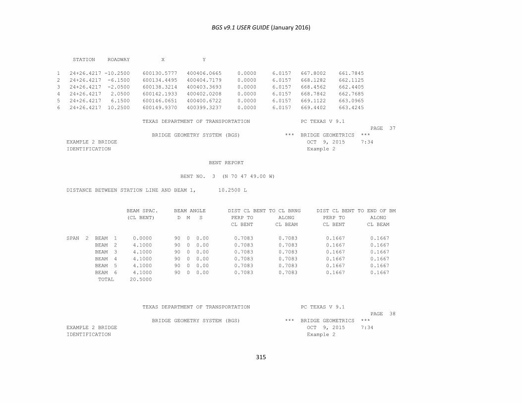
BGS v9.1 USER GUIDE (January 2016)
315
STATION ROADWAY X Y
1 24+26.4217 -10.2500 600130.5777 400406.0665 0.0000 6.0157 667.8002 661.7845
2 24+26.4217 -6.1500 600134.4495 400404.7179 0.0000 6.0157 668.1282 662.1125
3 24+26.4217 -2.0500 600138.3214 400403.3693 0.0000 6.0157 668.4562 662.4405
4 24+26.4217 2.0500 600142.1933 400402.0208 0.0000 6.0157 668.7842 662.7685
5 24+26.4217 6.1500 600146.0651 400400.6722 0.0000 6.0157 669.1122 663.0965
6 24+26.4217 10.2500 600149.9370 400399.3237 0.0000 6.0157 669.4402 663.4245
TEXAS DEPARTMENT OF TRANSPORTATION PC TEXAS V 9.1
PAGE 37
BRIDGE GEOMETRY SYSTEM (BGS) *** BRIDGE GEOMETRICS ***
EXAMPLE 2 BRIDGE OCT 9, 2015 7:34
IDENTIFICATION Example 2
BENT REPORT
BENT NO. 3 (N 70 47 49.00 W)
DISTANCE BETWEEN STATION LINE AND BEAM 1, 10.2500 L
BEAM SPAC. BEAM ANGLE DIST CL BENT TO CL BRNG DIST CL BENT TO END OF BM
(CL BENT) D M S PERP TO ALONG PERP TO ALONG
CL BENT CL BEAM CL BENT CL BEAM
SPAN 2 BEAM 1 0.0000 90 0 0.00 0.7083 0.7083 0.1667 0.1667
BEAM 2 4.1000 90 0 0.00 0.7083 0.7083 0.1667 0.1667
BEAM 3 4.1000 90 0 0.00 0.7083 0.7083 0.1667 0.1667
BEAM 4 4.1000 90 0 0.00 0.7083 0.7083 0.1667 0.1667
BEAM 5 4.1000 90 0 0.00 0.7083 0.7083 0.1667 0.1667
BEAM 6 4.1000 90 0 0.00 0.7083 0.7083 0.1667 0.1667
TOTAL 20.5000
TEXAS DEPARTMENT OF TRANSPORTATION PC TEXAS V 9.1
PAGE 38
BRIDGE GEOMETRY SYSTEM (BGS) *** BRIDGE GEOMETRICS ***
EXAMPLE 2 BRIDGE OCT 9, 2015 7:34
IDENTIFICATION Example 2
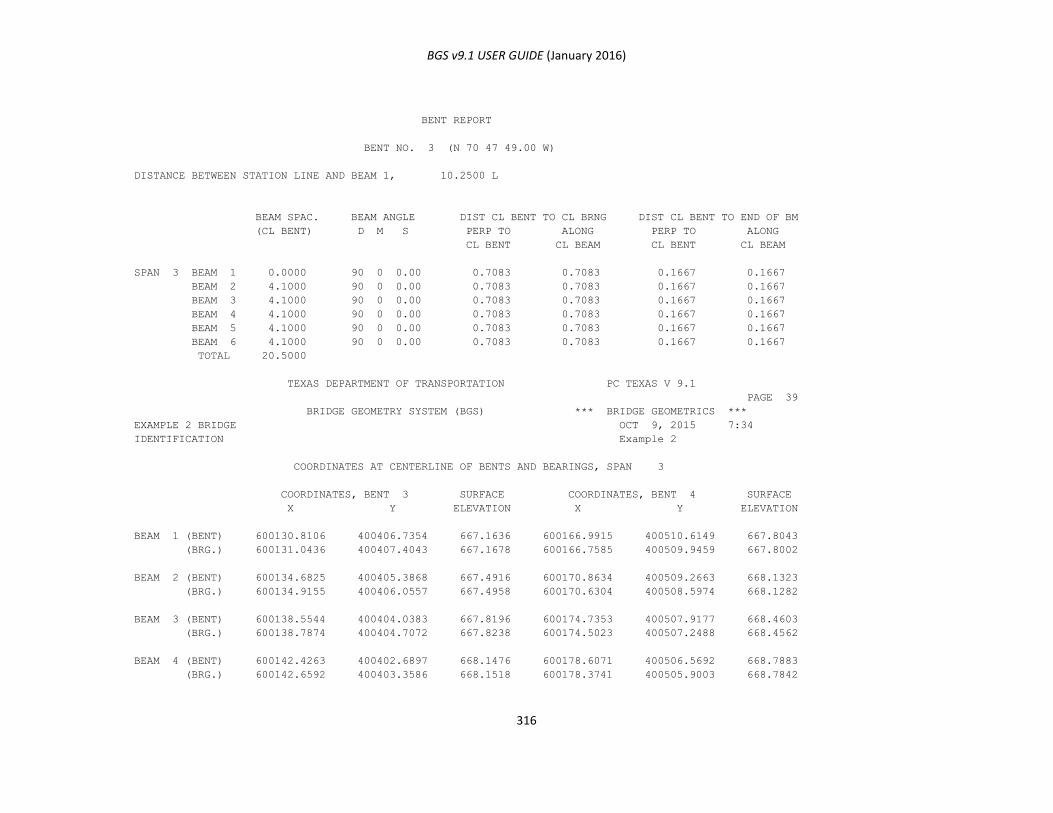
BGS v9.1 USER GUIDE (January 2016)
316
BENT REPORT
BENT NO. 3 (N 70 47 49.00 W)
DISTANCE BETWEEN STATION LINE AND BEAM 1, 10.2500 L
BEAM SPAC. BEAM ANGLE DIST CL BENT TO CL BRNG DIST CL BENT TO END OF BM
(CL BENT) D M S PERP TO ALONG PERP TO ALONG
CL BENT CL BEAM CL BENT CL BEAM
SPAN 3 BEAM 1 0.0000 90 0 0.00 0.7083 0.7083 0.1667 0.1667
BEAM 2 4.1000 90 0 0.00 0.7083 0.7083 0.1667 0.1667
BEAM 3 4.1000 90 0 0.00 0.7083 0.7083 0.1667 0.1667
BEAM 4 4.1000 90 0 0.00 0.7083 0.7083 0.1667 0.1667
BEAM 5 4.1000 90 0 0.00 0.7083 0.7083 0.1667 0.1667
BEAM 6 4.1000 90 0 0.00 0.7083 0.7083 0.1667 0.1667
TOTAL 20.5000
TEXAS DEPARTMENT OF TRANSPORTATION PC TEXAS V 9.1
PAGE 39
BRIDGE GEOMETRY SYSTEM (BGS) *** BRIDGE GEOMETRICS ***
EXAMPLE 2 BRIDGE OCT 9, 2015 7:34
IDENTIFICATION Example 2
COORDINATES AT CENTERLINE OF BENTS AND BEARINGS, SPAN 3
COORDINATES, BENT 3 SURFACE COORDINATES, BENT 4 SURFACE
X Y ELEVATION X Y ELEVATION
BEAM 1 (BENT) 600130.8106 400406.7354 667.1636 600166.9915 400510.6149 667.8043
(BRG.) 600131.0436 400407.4043 667.1678 600166.7585 400509.9459 667.8002
BEAM 2 (BENT) 600134.6825 400405.3868 667.4916 600170.8634 400509.2663 668.1323
(BRG.) 600134.9155 400406.0557 667.4958 600170.6304 400508.5974 668.1282
BEAM 3 (BENT) 600138.5544 400404.0383 667.8196 600174.7353 400507.9177 668.4603
(BRG.) 600138.7874 400404.7072 667.8238 600174.5023 400507.2488 668.4562
BEAM 4 (BENT) 600142.4263 400402.6897 668.1476 600178.6071 400506.5692 668.7883
(BRG.) 600142.6592 400403.3586 668.1518 600178.3741 400505.9003 668.7842
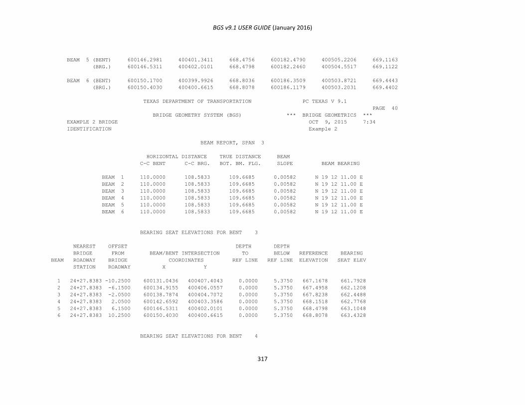
BGS v9.1 USER GUIDE (January 2016)
317
BEAM 5 (BENT) 600146.2981 400401.3411 668.4756 600182.4790 400505.2206 669.1163
(BRG.) 600146.5311 400402.0101 668.4798 600182.2460 400504.5517 669.1122
BEAM 6 (BENT) 600150.1700 400399.9926 668.8036 600186.3509 400503.8721 669.4443
(BRG.) 600150.4030 400400.6615 668.8078 600186.1179 400503.2031 669.4402
TEXAS DEPARTMENT OF TRANSPORTATION PC TEXAS V 9.1
PAGE 40
BRIDGE GEOMETRY SYSTEM (BGS) *** BRIDGE GEOMETRICS ***
EXAMPLE 2 BRIDGE OCT 9, 2015 7:34
IDENTIFICATION Example 2
BEAM REPORT, SPAN 3
HORIZONTAL DISTANCE TRUE DISTANCE BEAM
C-C BENT C-C BRG. BOT. BM. FLG. SLOPE BEAM BEARING
BEAM 1 110.0000 108.5833 109.6685 0.00582 N 19 12 11.00 E
BEAM 2 110.0000 108.5833 109.6685 0.00582 N 19 12 11.00 E
BEAM 3 110.0000 108.5833 109.6685 0.00582 N 19 12 11.00 E
BEAM 4 110.0000 108.5833 109.6685 0.00582 N 19 12 11.00 E
BEAM 5 110.0000 108.5833 109.6685 0.00582 N 19 12 11.00 E
BEAM 6 110.0000 108.5833 109.6685 0.00582 N 19 12 11.00 E
BEARING SEAT ELEVATIONS FOR BENT 3
NEAREST OFFSET DEPTH DEPTH
BRIDGE FROM BEAM/BENT INTERSECTION TO BELOW REFERENCE BEARING
BEAM ROADWAY BRIDGE COORDINATES REF LINE REF LINE ELEVATION SEAT ELEV
STATION ROADWAY X Y
1 24+27.8383 -10.2500 600131.0436 400407.4043 0.0000 5.3750 667.1678 661.7928
2 24+27.8383 -6.1500 600134.9155 400406.0557 0.0000 5.3750 667.4958 662.1208
3 24+27.8383 -2.0500 600138.7874 400404.7072 0.0000 5.3750 667.8238 662.4488
4 24+27.8383 2.0500 600142.6592 400403.3586 0.0000 5.3750 668.1518 662.7768
5 24+27.8383 6.1500 600146.5311 400402.0101 0.0000 5.3750 668.4798 663.1048
6 24+27.8383 10.2500 600150.4030 400400.6615 0.0000 5.3750 668.8078 663.4328
BEARING SEAT ELEVATIONS FOR BENT 4
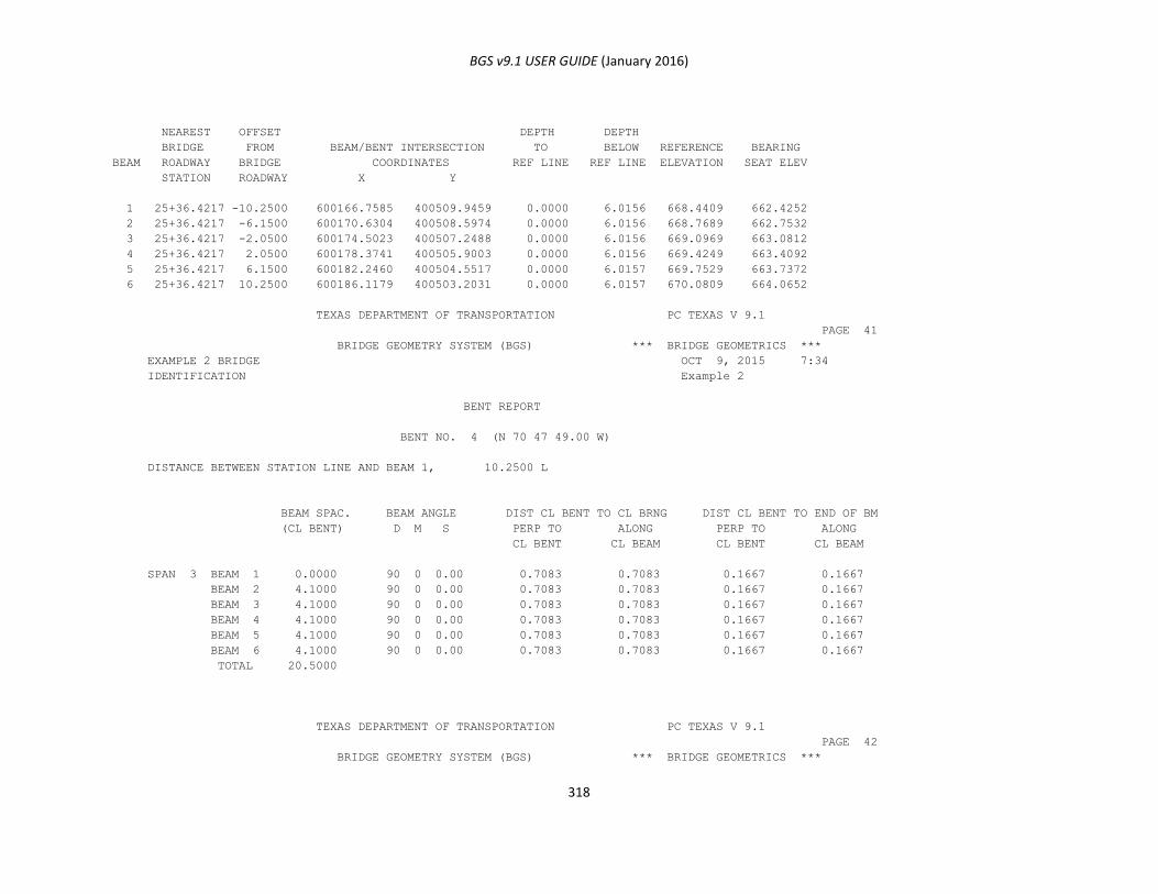
BGS v9.1 USER GUIDE (January 2016)
318
NEAREST OFFSET DEPTH DEPTH
BRIDGE FROM BEAM/BENT INTERSECTION TO BELOW REFERENCE BEARING
BEAM ROADWAY BRIDGE COORDINATES REF LINE REF LINE ELEVATION SEAT ELEV
STATION ROADWAY X Y
1 25+36.4217 -10.2500 600166.7585 400509.9459 0.0000 6.0156 668.4409 662.4252
2 25+36.4217 -6.1500 600170.6304 400508.5974 0.0000 6.0156 668.7689 662.7532
3 25+36.4217 -2.0500 600174.5023 400507.2488 0.0000 6.0156 669.0969 663.0812
4 25+36.4217 2.0500 600178.3741 400505.9003 0.0000 6.0156 669.4249 663.4092
5 25+36.4217 6.1500 600182.2460 400504.5517 0.0000 6.0157 669.7529 663.7372
6 25+36.4217 10.2500 600186.1179 400503.2031 0.0000 6.0157 670.0809 664.0652
TEXAS DEPARTMENT OF TRANSPORTATION PC TEXAS V 9.1
PAGE 41
BRIDGE GEOMETRY SYSTEM (BGS) *** BRIDGE GEOMETRICS ***
EXAMPLE 2 BRIDGE OCT 9, 2015 7:34
IDENTIFICATION Example 2
BENT REPORT
BENT NO. 4 (N 70 47 49.00 W)
DISTANCE BETWEEN STATION LINE AND BEAM 1, 10.2500 L
BEAM SPAC. BEAM ANGLE DIST CL BENT TO CL BRNG DIST CL BENT TO END OF BM
(CL BENT) D M S PERP TO ALONG PERP TO ALONG
CL BENT CL BEAM CL BENT CL BEAM
SPAN 3 BEAM 1 0.0000 90 0 0.00 0.7083 0.7083 0.1667 0.1667
BEAM 2 4.1000 90 0 0.00 0.7083 0.7083 0.1667 0.1667
BEAM 3 4.1000 90 0 0.00 0.7083 0.7083 0.1667 0.1667
BEAM 4 4.1000 90 0 0.00 0.7083 0.7083 0.1667 0.1667
BEAM 5 4.1000 90 0 0.00 0.7083 0.7083 0.1667 0.1667
BEAM 6 4.1000 90 0 0.00 0.7083 0.7083 0.1667 0.1667
TOTAL 20.5000
TEXAS DEPARTMENT OF TRANSPORTATION PC TEXAS V 9.1
PAGE 42
BRIDGE GEOMETRY SYSTEM (BGS) *** BRIDGE GEOMETRICS ***
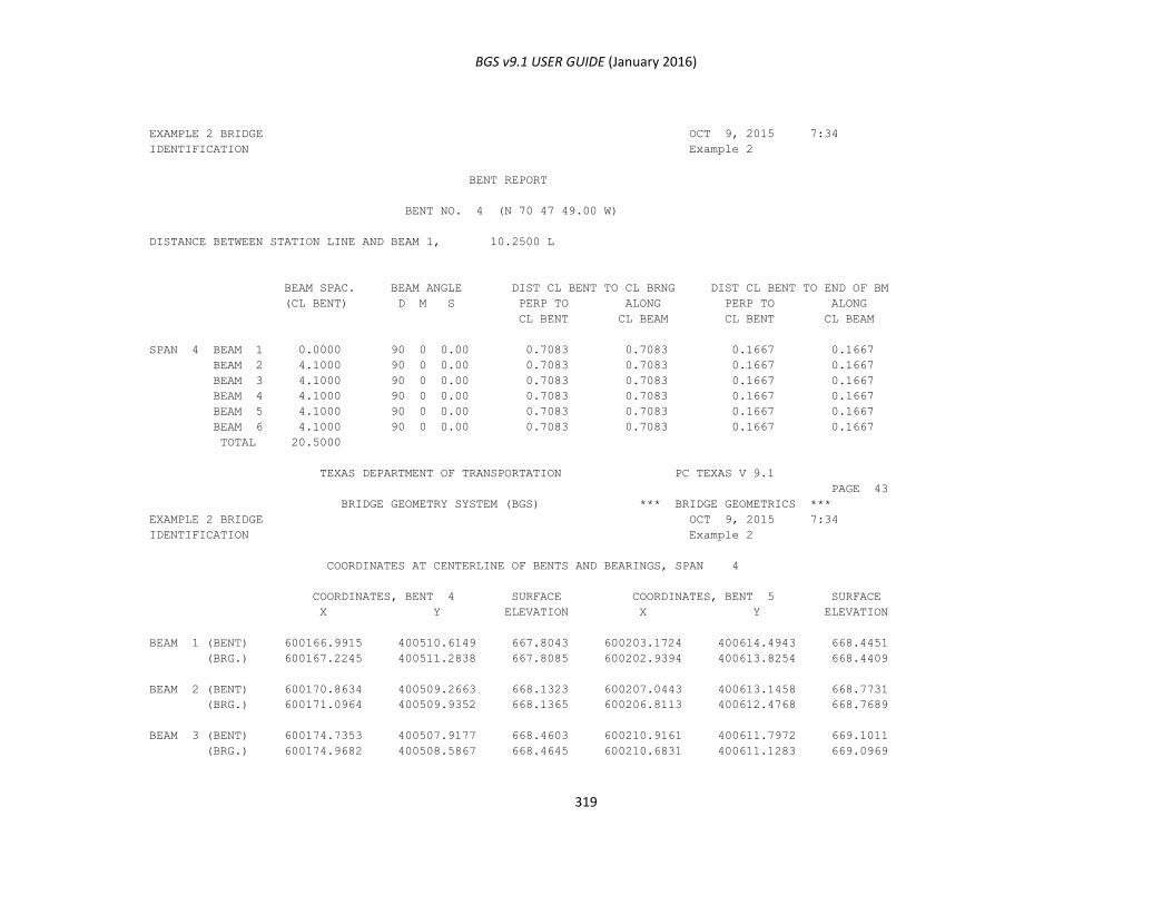
BGS v9.1 USER GUIDE (January 2016)
319
EXAMPLE 2 BRIDGE OCT 9, 2015 7:34
IDENTIFICATION Example 2
BENT REPORT
BENT NO. 4 (N 70 47 49.00 W)
DISTANCE BETWEEN STATION LINE AND BEAM 1, 10.2500 L
BEAM SPAC. BEAM ANGLE DIST CL BENT TO CL BRNG DIST CL BENT TO END OF BM
(CL BENT) D M S PERP TO ALONG PERP TO ALONG
CL BENT CL BEAM CL BENT CL BEAM
SPAN 4 BEAM 1 0.0000 90 0 0.00 0.7083 0.7083 0.1667 0.1667
BEAM 2 4.1000 90 0 0.00 0.7083 0.7083 0.1667 0.1667
BEAM 3 4.1000 90 0 0.00 0.7083 0.7083 0.1667 0.1667
BEAM 4 4.1000 90 0 0.00 0.7083 0.7083 0.1667 0.1667
BEAM 5 4.1000 90 0 0.00 0.7083 0.7083 0.1667 0.1667
BEAM 6 4.1000 90 0 0.00 0.7083 0.7083 0.1667 0.1667
TOTAL 20.5000
TEXAS DEPARTMENT OF TRANSPORTATION PC TEXAS V 9.1
PAGE 43
BRIDGE GEOMETRY SYSTEM (BGS) *** BRIDGE GEOMETRICS ***
EXAMPLE 2 BRIDGE OCT 9, 2015 7:34
IDENTIFICATION Example 2
COORDINATES AT CENTERLINE OF BENTS AND BEARINGS, SPAN 4
COORDINATES, BENT 4 SURFACE COORDINATES, BENT 5 SURFACE
X Y ELEVATION X Y ELEVATION
BEAM 1 (BENT) 600166.9915 400510.6149 667.8043 600203.1724 400614.4943 668.4451
(BRG.) 600167.2245 400511.2838 667.8085 600202.9394 400613.8254 668.4409
BEAM 2 (BENT) 600170.8634 400509.2663 668.1323 600207.0443 400613.1458 668.7731
(BRG.) 600171.0964 400509.9352 668.1365 600206.8113 400612.4768 668.7689
BEAM 3 (BENT) 600174.7353 400507.9177 668.4603 600210.9161 400611.7972 669.1011
(BRG.) 600174.9682 400508.5867 668.4645 600210.6831 400611.1283 669.0969
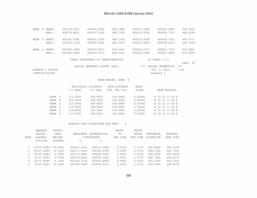
BGS v9.1 USER GUIDE (January 2016)
320
BEAM 4 (BENT) 600178.6071 400506.5692 668.7883 600214.7880 400610.4487 669.4291
(BRG.) 600178.8401 400507.2381 668.7925 600214.5550 400609.7797 669.4249
BEAM 5 (BENT) 600182.4790 400505.2206 669.1163 600218.6599 400609.1001 669.7571
(BRG.) 600182.7120 400505.8895 669.1205 600218.4269 400608.4312 669.7529
BEAM 6 (BENT) 600186.3509 400503.8721 669.4443 600222.5317 400607.7515 670.0851
(BRG.) 600186.5839 400504.5410 669.4485 600222.2988 400607.0826 670.0809
TEXAS DEPARTMENT OF TRANSPORTATION PC TEXAS V 9.1
PAGE 44
BRIDGE GEOMETRY SYSTEM (BGS) *** BRIDGE GEOMETRICS ***
EXAMPLE 2 BRIDGE OCT 9, 2015 7:34
IDENTIFICATION Example 2
BEAM REPORT, SPAN 4
HORIZONTAL DISTANCE TRUE DISTANCE BEAM
C-C BENT C-C BRG. BOT. BM. FLG. SLOPE BEAM BEARING
BEAM 1 110.0000 108.5833 109.6685 0.00582 N 19 12 11.00 E
BEAM 2 110.0000 108.5833 109.6685 0.00582 N 19 12 11.00 E
BEAM 3 110.0000 108.5833 109.6685 0.00582 N 19 12 11.00 E
BEAM 4 110.0000 108.5833 109.6685 0.00582 N 19 12 11.00 E
BEAM 5 110.0000 108.5833 109.6685 0.00582 N 19 12 11.00 E
BEAM 6 110.0000 108.5833 109.6685 0.00582 N 19 12 11.00 E
BEARING SEAT ELEVATIONS FOR BENT 4
NEAREST OFFSET DEPTH DEPTH
BRIDGE FROM BEAM/BENT INTERSECTION TO BELOW REFERENCE BEARING
BEAM ROADWAY BRIDGE COORDINATES REF LINE REF LINE ELEVATION SEAT ELEV
STATION ROADWAY X Y
1 25+37.8383 -10.2500 600167.2245 400511.2838 0.0000 5.3750 667.8085 662.4335
2 25+37.8383 -6.1500 600171.0964 400509.9352 0.0000 5.3750 668.1365 662.7615
3 25+37.8383 -2.0500 600174.9682 400508.5867 0.0000 5.3750 668.4645 663.0895
4 25+37.8383 2.0500 600178.8401 400507.2381 0.0000 5.3750 668.7925 663.4175
5 25+37.8383 6.1500 600182.7120 400505.8895 0.0000 5.3750 669.1205 663.7455
6 25+37.8383 10.2500 600186.5839 400504.5410 0.0000 5.3750 669.4485 664.0735
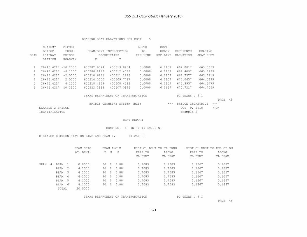
BGS v9.1 USER GUIDE (January 2016)
321
BEARING SEAT ELEVATIONS FOR BENT 5
NEAREST OFFSET DEPTH DEPTH
BRIDGE FROM BEAM/BENT INTERSECTION TO BELOW REFERENCE BEARING
BEAM ROADWAY BRIDGE COORDINATES REF LINE REF LINE ELEVATION SEAT ELEV
STATION ROADWAY X Y
1 26+46.4217 -10.2500 600202.9394 400613.8254 0.0000 6.0157 669.0817 663.0659
2 26+46.4217 -6.1500 600206.8113 400612.4768 0.0000 6.0157 669.4097 663.3939
3 26+46.4217 -2.0500 600210.6831 400611.1283 0.0000 6.0157 669.7377 663.7219
4 26+46.4217 2.0500 600214.5550 400609.7797 0.0000 6.0157 670.0657 664.0499
5 26+46.4217 6.1500 600218.4269 400608.4312 0.0000 6.0157 670.3937 664.3779
6 26+46.4217 10.2500 600222.2988 400607.0826 0.0000 6.0157 670.7217 664.7059
TEXAS DEPARTMENT OF TRANSPORTATION PC TEXAS V 9.1
PAGE 45
BRIDGE GEOMETRY SYSTEM (BGS) *** BRIDGE GEOMETRICS ***
EXAMPLE 2 BRIDGE OCT 9, 2015 7:34
IDENTIFICATION Example 2
BENT REPORT
BENT NO. 5 (N 70 47 49.00 W)
DISTANCE BETWEEN STATION LINE AND BEAM 1, 10.2500 L
BEAM SPAC. BEAM ANGLE DIST CL BENT TO CL BRNG DIST CL BENT TO END OF BM
(CL BENT) D M S PERP TO ALONG PERP TO ALONG
CL BENT CL BEAM CL BENT CL BEAM
SPAN 4 BEAM 1 0.0000 90 0 0.00 0.7083 0.7083 0.1667 0.1667
BEAM 2 4.1000 90 0 0.00 0.7083 0.7083 0.1667 0.1667
BEAM 3 4.1000 90 0 0.00 0.7083 0.7083 0.1667 0.1667
BEAM 4 4.1000 90 0 0.00 0.7083 0.7083 0.1667 0.1667
BEAM 5 4.1000 90 0 0.00 0.7083 0.7083 0.1667 0.1667
BEAM 6 4.1000 90 0 0.00 0.7083 0.7083 0.1667 0.1667
TOTAL 20.5000
TEXAS DEPARTMENT OF TRANSPORTATION PC TEXAS V 9.1
PAGE 46
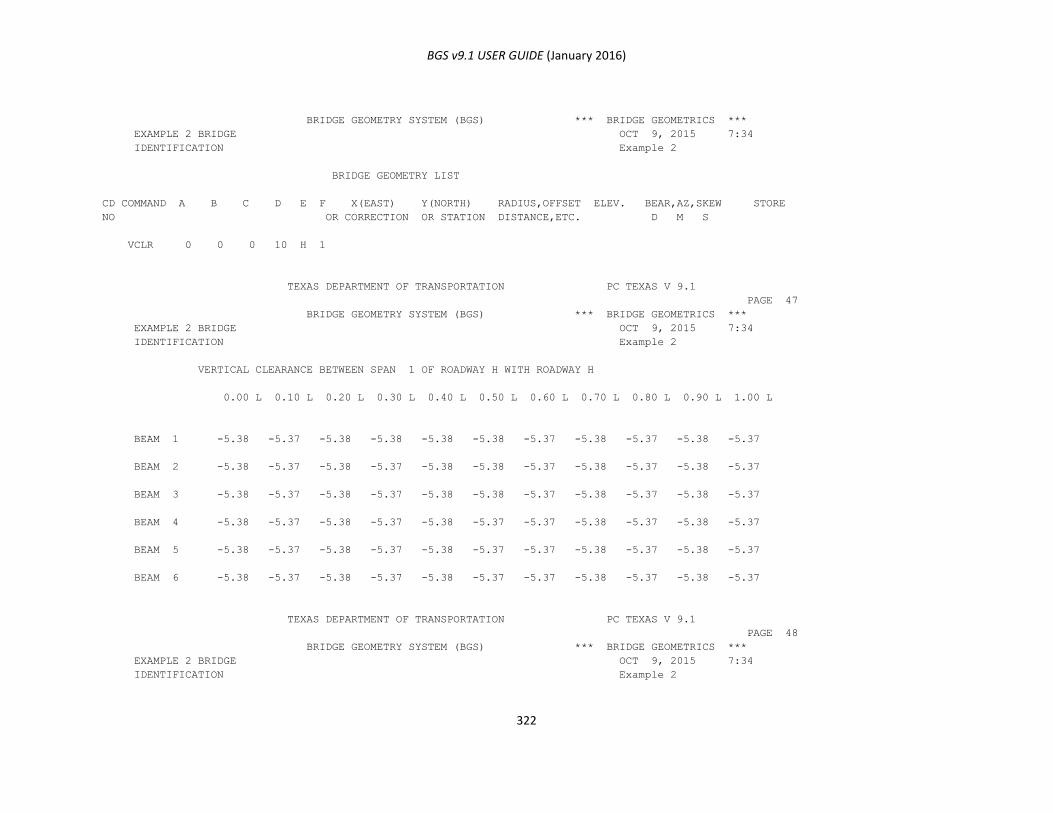
BGS v9.1 USER GUIDE (January 2016)
322
BRIDGE GEOMETRY SYSTEM (BGS) *** BRIDGE GEOMETRICS ***
EXAMPLE 2 BRIDGE OCT 9, 2015 7:34
IDENTIFICATION Example 2
BRIDGE GEOMETRY LIST
CD COMMAND A B C D E F X(EAST) Y(NORTH) RADIUS,OFFSET ELEV. BEAR,AZ,SKEW STORE
NO OR CORRECTION OR STATION DISTANCE,ETC. D M S
VCLR 0 0 0 10 H 1
TEXAS DEPARTMENT OF TRANSPORTATION PC TEXAS V 9.1
PAGE 47
BRIDGE GEOMETRY SYSTEM (BGS) *** BRIDGE GEOMETRICS ***
EXAMPLE 2 BRIDGE OCT 9, 2015 7:34
IDENTIFICATION Example 2
VERTICAL CLEARANCE BETWEEN SPAN 1 OF ROADWAY H WITH ROADWAY H
0.00 L 0.10 L 0.20 L 0.30 L 0.40 L 0.50 L 0.60 L 0.70 L 0.80 L 0.90 L 1.00 L
BEAM 1 -5.38 -5.37 -5.38 -5.38 -5.38 -5.38 -5.37 -5.38 -5.37 -5.38 -5.37
BEAM 2 -5.38 -5.37 -5.38 -5.37 -5.38 -5.38 -5.37 -5.38 -5.37 -5.38 -5.37
BEAM 3 -5.38 -5.37 -5.38 -5.37 -5.38 -5.38 -5.37 -5.38 -5.37 -5.38 -5.37
BEAM 4 -5.38 -5.37 -5.38 -5.37 -5.38 -5.37 -5.37 -5.38 -5.37 -5.38 -5.37
BEAM 5 -5.38 -5.37 -5.38 -5.37 -5.38 -5.37 -5.37 -5.38 -5.37 -5.38 -5.37
BEAM 6 -5.38 -5.37 -5.38 -5.37 -5.38 -5.37 -5.37 -5.38 -5.37 -5.38 -5.37
TEXAS DEPARTMENT OF TRANSPORTATION PC TEXAS V 9.1
PAGE 48
BRIDGE GEOMETRY SYSTEM (BGS) *** BRIDGE GEOMETRICS ***
EXAMPLE 2 BRIDGE OCT 9, 2015 7:34
IDENTIFICATION Example 2
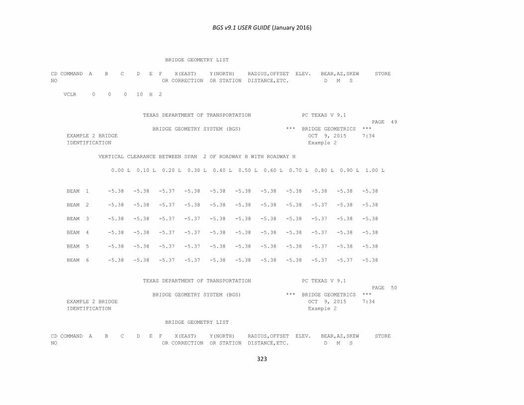
BGS v9.1 USER GUIDE (January 2016)
323
BRIDGE GEOMETRY LIST
CD COMMAND A B C D E F X(EAST) Y(NORTH) RADIUS,OFFSET ELEV. BEAR,AZ,SKEW STORE
NO OR CORRECTION OR STATION DISTANCE,ETC. D M S
VCLR 0 0 0 10 H 2
TEXAS DEPARTMENT OF TRANSPORTATION PC TEXAS V 9.1
PAGE 49
BRIDGE GEOMETRY SYSTEM (BGS) *** BRIDGE GEOMETRICS ***
EXAMPLE 2 BRIDGE OCT 9, 2015 7:34
IDENTIFICATION Example 2
VERTICAL CLEARANCE BETWEEN SPAN 2 OF ROADWAY H WITH ROADWAY H
0.00 L 0.10 L 0.20 L 0.30 L 0.40 L 0.50 L 0.60 L 0.70 L 0.80 L 0.90 L 1.00 L
BEAM 1 -5.38 -5.38 -5.37 -5.38 -5.38 -5.38 -5.38 -5.38 -5.38 -5.38 -5.38
BEAM 2 -5.38 -5.38 -5.37 -5.38 -5.38 -5.38 -5.38 -5.38 -5.37 -5.38 -5.38
BEAM 3 -5.38 -5.38 -5.37 -5.37 -5.38 -5.38 -5.38 -5.38 -5.37 -5.38 -5.38
BEAM 4 -5.38 -5.38 -5.37 -5.37 -5.38 -5.38 -5.38 -5.38 -5.37 -5.38 -5.38
BEAM 5 -5.38 -5.38 -5.37 -5.37 -5.38 -5.38 -5.38 -5.38 -5.37 -5.38 -5.38
BEAM 6 -5.38 -5.38 -5.37 -5.37 -5.38 -5.38 -5.38 -5.38 -5.37 -5.37 -5.38
TEXAS DEPARTMENT OF TRANSPORTATION PC TEXAS V 9.1
PAGE 50
BRIDGE GEOMETRY SYSTEM (BGS) *** BRIDGE GEOMETRICS ***
EXAMPLE 2 BRIDGE OCT 9, 2015 7:34
IDENTIFICATION Example 2
BRIDGE GEOMETRY LIST
CD COMMAND A B C D E F X(EAST) Y(NORTH) RADIUS,OFFSET ELEV. BEAR,AZ,SKEW STORE
NO OR CORRECTION OR STATION DISTANCE,ETC. D M S

BGS v9.1 USER GUIDE (January 2016)
324
VCLR 0 0 0 10 H 3
TEXAS DEPARTMENT OF TRANSPORTATION PC TEXAS V 9.1
PAGE 51
BRIDGE GEOMETRY SYSTEM (BGS) *** BRIDGE GEOMETRICS ***
EXAMPLE 2 BRIDGE OCT 9, 2015 7:34
IDENTIFICATION Example 2
VERTICAL CLEARANCE BETWEEN SPAN 3 OF ROADWAY H WITH ROADWAY H
0.00 L 0.10 L 0.20 L 0.30 L 0.40 L 0.50 L 0.60 L 0.70 L 0.80 L 0.90 L 1.00 L
BEAM 1 -5.37 -5.38 -5.37 -5.37 -5.37 -5.37 -5.38 -5.38 -5.37 -5.37 -5.37
BEAM 2 -5.37 -5.38 -5.37 -5.37 -5.37 -5.37 -5.38 -5.38 -5.37 -5.37 -5.37
BEAM 3 -5.37 -5.38 -5.37 -5.37 -5.37 -5.37 -5.37 -5.38 -5.37 -5.37 -5.37
BEAM 4 -5.37 -5.37 -5.37 -5.37 -5.37 -5.37 -5.37 -5.38 -5.37 -5.37 -5.37
BEAM 5 -5.37 -5.38 -5.37 -5.37 -5.37 -5.38 -5.38 -5.38 -5.38 -5.38 -5.38
BEAM 6 -5.37 -5.37 -5.37 -5.37 -5.37 -5.38 -5.38 -5.38 -5.38 -5.38 -5.38
TEXAS DEPARTMENT OF TRANSPORTATION PC TEXAS V 9.1
PAGE 52
BRIDGE GEOMETRY SYSTEM (BGS) *** BRIDGE GEOMETRICS ***
EXAMPLE 2 BRIDGE OCT 9, 2015 7:34
IDENTIFICATION Example 2
BRIDGE GEOMETRY LIST
CD COMMAND A B C D E F X(EAST) Y(NORTH) RADIUS,OFFSET ELEV. BEAR,AZ,SKEW STORE
NO OR CORRECTION OR STATION DISTANCE,ETC. D M S
VCLR 0 0 0 10 H 4

BGS v9.1 USER GUIDE (January 2016)
325
TEXAS DEPARTMENT OF TRANSPORTATION PC TEXAS V 9.1
PAGE 53
BRIDGE GEOMETRY SYSTEM (BGS) *** BRIDGE GEOMETRICS ***
EXAMPLE 2 BRIDGE OCT 9, 2015 7:34
IDENTIFICATION Example 2
VERTICAL CLEARANCE BETWEEN SPAN 4 OF ROADWAY H WITH ROADWAY H
0.00 L 0.10 L 0.20 L 0.30 L 0.40 L 0.50 L 0.60 L 0.70 L 0.80 L 0.90 L 1.00 L
BEAM 1 -5.38 -5.38 -5.37 -5.37 -5.38 -5.38 -5.38 -5.38 -5.37 -5.38 -5.38
BEAM 2 -5.38 -5.38 -5.37 -5.37 -5.38 -5.38 -5.38 -5.38 -5.37 -5.38 -5.38
BEAM 3 -5.38 -5.38 -5.37 -5.37 -5.38 -5.38 -5.38 -5.38 -5.37 -5.38 -5.38
BEAM 4 -5.38 -5.38 -5.37 -5.37 -5.37 -5.38 -5.38 -5.38 -5.37 -5.37 -5.38
BEAM 5 -5.38 -5.38 -5.37 -5.37 -5.37 -5.38 -5.38 -5.38 -5.37 -5.37 -5.38
BEAM 6 -5.38 -5.38 -5.37 -5.37 -5.37 -5.38 -5.38 -5.38 -5.37 -5.37 -5.38
TEXAS DEPARTMENT OF TRANSPORTATION PC TEXAS V 9.1
PAGE 54
BRIDGE GEOMETRY SYSTEM (BGS) *** BRIDGE GEOMETRICS ***
EXAMPLE 2 BRIDGE OCT 9, 2015 7:34
IDENTIFICATION Example 2
BRIDGE GEOMETRY LIST
CD COMMAND A B C D E F X(EAST) Y(NORTH) RADIUS,OFFSET ELEV. BEAR,AZ,SKEW STORE
NO OR CORRECTION OR STATION DISTANCE,ETC. D M S
VCLR 0 0 0 10 I 1
TEXAS DEPARTMENT OF TRANSPORTATION PC TEXAS V 9.1
PAGE 55
BRIDGE GEOMETRY SYSTEM (BGS) *** BRIDGE GEOMETRICS ***
EXAMPLE 2 BRIDGE OCT 9, 2015 7:34
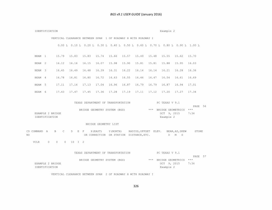
BGS v9.1 USER GUIDE (January 2016)
326
IDENTIFICATION Example 2
VERTICAL CLEARANCE BETWEEN SPAN 1 OF ROADWAY H WITH ROADWAY I
0.00 L 0.10 L 0.20 L 0.30 L 0.40 L 0.50 L 0.60 L 0.70 L 0.80 L 0.90 L 1.00 L
BEAM 1 15.79 15.83 15.83 15.74 15.66 15.57 15.49 15.48 15.55 15.62 15.70
BEAM 2 16.12 16.16 16.15 16.07 15.98 15.90 15.81 15.81 15.88 15.95 16.03
BEAM 3 16.45 16.49 16.48 16.39 16.31 16.22 16.14 16.14 16.21 16.28 16.36
BEAM 4 16.78 16.81 16.80 16.72 16.63 16.55 16.46 16.47 16.54 16.61 16.69
BEAM 5 17.11 17.14 17.13 17.04 16.96 16.87 16.79 16.79 16.87 16.94 17.01
BEAM 6 17.43 17.47 17.45 17.36 17.28 17.19 17.11 17.12 17.20 17.27 17.34
TEXAS DEPARTMENT OF TRANSPORTATION PC TEXAS V 9.1
PAGE 56
BRIDGE GEOMETRY SYSTEM (BGS) *** BRIDGE GEOMETRICS ***
EXAMPLE 2 BRIDGE OCT 9, 2015 7:34
IDENTIFICATION Example 2
BRIDGE GEOMETRY LIST
CD COMMAND A B C D E F X(EAST) Y(NORTH) RADIUS,OFFSET ELEV. BEAR,AZ,SKEW STORE
NO OR CORRECTION OR STATION DISTANCE,ETC. D M S
VCLR 0 0 0 10 I 2
TEXAS DEPARTMENT OF TRANSPORTATION PC TEXAS V 9.1
PAGE 57
BRIDGE GEOMETRY SYSTEM (BGS) *** BRIDGE GEOMETRICS ***
EXAMPLE 2 BRIDGE OCT 9, 2015 7:34
IDENTIFICATION Example 2
VERTICAL CLEARANCE BETWEEN SPAN 2 OF ROADWAY H WITH ROADWAY I
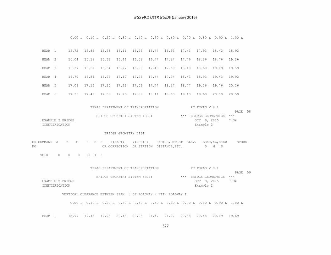
BGS v9.1 USER GUIDE (January 2016)
327
0.00 L 0.10 L 0.20 L 0.30 L 0.40 L 0.50 L 0.60 L 0.70 L 0.80 L 0.90 L 1.00 L
BEAM 1 15.72 15.85 15.98 16.11 16.25 16.44 16.93 17.43 17.93 18.42 18.92
BEAM 2 16.04 16.18 16.31 16.44 16.58 16.77 17.27 17.76 18.26 18.76 19.26
BEAM 3 16.37 16.51 16.64 16.77 16.90 17.10 17.60 18.10 18.60 19.09 19.59
BEAM 4 16.70 16.84 16.97 17.10 17.23 17.44 17.94 18.43 18.93 19.43 19.92
BEAM 5 17.03 17.16 17.30 17.43 17.56 17.77 18.27 18.77 19.26 19.76 20.26
BEAM 6 17.36 17.49 17.63 17.76 17.89 18.11 18.60 19.10 19.60 20.10 20.59
TEXAS DEPARTMENT OF TRANSPORTATION PC TEXAS V 9.1
PAGE 58
BRIDGE GEOMETRY SYSTEM (BGS) *** BRIDGE GEOMETRICS ***
EXAMPLE 2 BRIDGE OCT 9, 2015 7:34
IDENTIFICATION Example 2
BRIDGE GEOMETRY LIST
CD COMMAND A B C D E F X(EAST) Y(NORTH) RADIUS,OFFSET ELEV. BEAR,AZ,SKEW STORE
NO OR CORRECTION OR STATION DISTANCE,ETC. D M S
VCLR 0 0 0 10 I 3
TEXAS DEPARTMENT OF TRANSPORTATION PC TEXAS V 9.1
PAGE 59
BRIDGE GEOMETRY SYSTEM (BGS) *** BRIDGE GEOMETRICS ***
EXAMPLE 2 BRIDGE OCT 9, 2015 7:34
IDENTIFICATION Example 2
VERTICAL CLEARANCE BETWEEN SPAN 3 OF ROADWAY H WITH ROADWAY I
0.00 L 0.10 L 0.20 L 0.30 L 0.40 L 0.50 L 0.60 L 0.70 L 0.80 L 0.90 L 1.00 L
BEAM 1 18.99 19.48 19.98 20.48 20.98 21.47 21.27 20.88 20.48 20.09 19.69
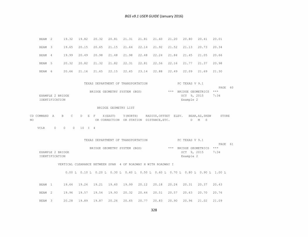
BGS v9.1 USER GUIDE (January 2016)
328
BEAM 2 19.32 19.82 20.32 20.81 21.31 21.81 21.60 21.20 20.80 20.41 20.01
BEAM 3 19.65 20.15 20.65 21.15 21.64 22.14 21.92 21.52 21.13 20.73 20.34
BEAM 4 19.99 20.49 20.98 21.48 21.98 22.48 22.24 21.84 21.45 21.05 20.66
BEAM 5 20.32 20.82 21.32 21.82 22.31 22.81 22.56 22.16 21.77 21.37 20.98
BEAM 6 20.66 21.16 21.65 22.15 22.65 23.14 22.88 22.49 22.09 21.69 21.30
TEXAS DEPARTMENT OF TRANSPORTATION PC TEXAS V 9.1
PAGE 60
BRIDGE GEOMETRY SYSTEM (BGS) *** BRIDGE GEOMETRICS ***
EXAMPLE 2 BRIDGE OCT 9, 2015 7:34
IDENTIFICATION Example 2
BRIDGE GEOMETRY LIST
CD COMMAND A B C D E F X(EAST) Y(NORTH) RADIUS,OFFSET ELEV. BEAR,AZ,SKEW STORE
NO OR CORRECTION OR STATION DISTANCE,ETC. D M S
VCLR 0 0 0 10 I 4
TEXAS DEPARTMENT OF TRANSPORTATION PC TEXAS V 9.1
PAGE 61
BRIDGE GEOMETRY SYSTEM (BGS) *** BRIDGE GEOMETRICS ***
EXAMPLE 2 BRIDGE OCT 9, 2015 7:34
IDENTIFICATION Example 2
VERTICAL CLEARANCE BETWEEN SPAN 4 OF ROADWAY H WITH ROADWAY I
0.00 L 0.10 L 0.20 L 0.30 L 0.40 L 0.50 L 0.60 L 0.70 L 0.80 L 0.90 L 1.00 L
BEAM 1 19.64 19.24 19.21 19.60 19.99 20.12 20.18 20.24 20.31 20.37 20.43
BEAM 2 19.96 19.57 19.54 19.93 20.32 20.44 20.51 20.57 20.63 20.70 20.76
BEAM 3 20.28 19.89 19.87 20.26 20.65 20.77 20.83 20.90 20.96 21.02 21.09
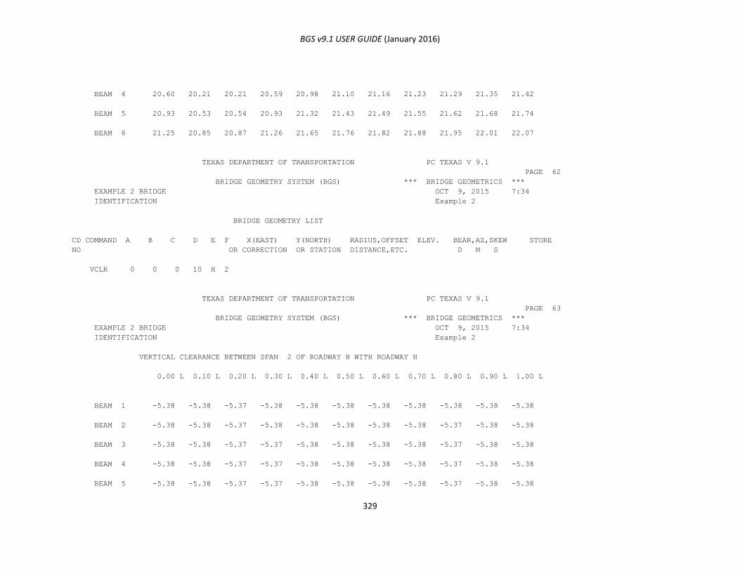
BGS v9.1 USER GUIDE (January 2016)
329
BEAM 4 20.60 20.21 20.21 20.59 20.98 21.10 21.16 21.23 21.29 21.35 21.42
BEAM 5 20.93 20.53 20.54 20.93 21.32 21.43 21.49 21.55 21.62 21.68 21.74
BEAM 6 21.25 20.85 20.87 21.26 21.65 21.76 21.82 21.88 21.95 22.01 22.07
TEXAS DEPARTMENT OF TRANSPORTATION PC TEXAS V 9.1
PAGE 62
BRIDGE GEOMETRY SYSTEM (BGS) *** BRIDGE GEOMETRICS ***
EXAMPLE 2 BRIDGE OCT 9, 2015 7:34
IDENTIFICATION Example 2
BRIDGE GEOMETRY LIST
CD COMMAND A B C D E F X(EAST) Y(NORTH) RADIUS,OFFSET ELEV. BEAR,AZ,SKEW STORE
NO OR CORRECTION OR STATION DISTANCE,ETC. D M S
VCLR 0 0 0 10 H 2
TEXAS DEPARTMENT OF TRANSPORTATION PC TEXAS V 9.1
PAGE 63
BRIDGE GEOMETRY SYSTEM (BGS) *** BRIDGE GEOMETRICS ***
EXAMPLE 2 BRIDGE OCT 9, 2015 7:34
IDENTIFICATION Example 2
VERTICAL CLEARANCE BETWEEN SPAN 2 OF ROADWAY H WITH ROADWAY H
0.00 L 0.10 L 0.20 L 0.30 L 0.40 L 0.50 L 0.60 L 0.70 L 0.80 L 0.90 L 1.00 L
BEAM 1 -5.38 -5.38 -5.37 -5.38 -5.38 -5.38 -5.38 -5.38 -5.38 -5.38 -5.38
BEAM 2 -5.38 -5.38 -5.37 -5.38 -5.38 -5.38 -5.38 -5.38 -5.37 -5.38 -5.38
BEAM 3 -5.38 -5.38 -5.37 -5.37 -5.38 -5.38 -5.38 -5.38 -5.37 -5.38 -5.38
BEAM 4 -5.38 -5.38 -5.37 -5.37 -5.38 -5.38 -5.38 -5.38 -5.37 -5.38 -5.38
BEAM 5 -5.38 -5.38 -5.37 -5.37 -5.38 -5.38 -5.38 -5.38 -5.37 -5.38 -5.38
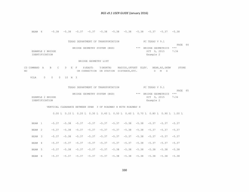
BGS v9.1 USER GUIDE (January 2016)
330
BEAM 6 -5.38 -5.38 -5.37 -5.37 -5.38 -5.38 -5.38 -5.38 -5.37 -5.37 -5.38
TEXAS DEPARTMENT OF TRANSPORTATION PC TEXAS V 9.1
PAGE 64
BRIDGE GEOMETRY SYSTEM (BGS) *** BRIDGE GEOMETRICS ***
EXAMPLE 2 BRIDGE OCT 9, 2015 7:34
IDENTIFICATION Example 2
BRIDGE GEOMETRY LIST
CD COMMAND A B C D E F X(EAST) Y(NORTH) RADIUS,OFFSET ELEV. BEAR,AZ,SKEW STORE
NO OR CORRECTION OR STATION DISTANCE,ETC. D M S
VCLR 0 0 0 10 H 3
TEXAS DEPARTMENT OF TRANSPORTATION PC TEXAS V 9.1
PAGE 65
BRIDGE GEOMETRY SYSTEM (BGS) *** BRIDGE GEOMETRICS ***
EXAMPLE 2 BRIDGE OCT 9, 2015 7:34
IDENTIFICATION Example 2
VERTICAL CLEARANCE BETWEEN SPAN 3 OF ROADWAY H WITH ROADWAY H
0.00 L 0.10 L 0.20 L 0.30 L 0.40 L 0.50 L 0.60 L 0.70 L 0.80 L 0.90 L 1.00 L
BEAM 1 -5.37 -5.38 -5.37 -5.37 -5.37 -5.37 -5.38 -5.38 -5.37 -5.37 -5.37
BEAM 2 -5.37 -5.38 -5.37 -5.37 -5.37 -5.37 -5.38 -5.38 -5.37 -5.37 -5.37
BEAM 3 -5.37 -5.38 -5.37 -5.37 -5.37 -5.37 -5.37 -5.38 -5.37 -5.37 -5.37
BEAM 4 -5.37 -5.37 -5.37 -5.37 -5.37 -5.37 -5.37 -5.38 -5.37 -5.37 -5.37
BEAM 5 -5.37 -5.38 -5.37 -5.37 -5.37 -5.38 -5.38 -5.38 -5.38 -5.38 -5.38
BEAM 6 -5.37 -5.37 -5.37 -5.37 -5.37 -5.38 -5.38 -5.38 -5.38 -5.38 -5.38

BGS v9.1 USER GUIDE (January 2016)
331
TEXAS DEPARTMENT OF TRANSPORTATION PC TEXAS V 9.1
PAGE 66
BRIDGE GEOMETRY SYSTEM (BGS) *** BRIDGE GEOMETRICS ***
EXAMPLE 2 BRIDGE OCT 9, 2015 7:34
IDENTIFICATION Example 2
BRIDGE GEOMETRY LIST
CD COMMAND A B C D E F X(EAST) Y(NORTH) RADIUS,OFFSET ELEV. BEAR,AZ,SKEW STORE
NO OR CORRECTION OR STATION DISTANCE,ETC. D M S
VCLR 0 0 0 10 H 4
TEXAS DEPARTMENT OF TRANSPORTATION PC TEXAS V 9.1
PAGE 67
BRIDGE GEOMETRY SYSTEM (BGS) *** BRIDGE GEOMETRICS ***
EXAMPLE 2 BRIDGE OCT 9, 2015 7:34
IDENTIFICATION Example 2
VERTICAL CLEARANCE BETWEEN SPAN 4 OF ROADWAY H WITH ROADWAY H
0.00 L 0.10 L 0.20 L 0.30 L 0.40 L 0.50 L 0.60 L 0.70 L 0.80 L 0.90 L 1.00 L
BEAM 1 -5.38 -5.38 -5.37 -5.37 -5.38 -5.38 -5.38 -5.38 -5.37 -5.38 -5.38
BEAM 2 -5.38 -5.38 -5.37 -5.37 -5.38 -5.38 -5.38 -5.38 -5.37 -5.38 -5.38
BEAM 3 -5.38 -5.38 -5.37 -5.37 -5.38 -5.38 -5.38 -5.38 -5.37 -5.38 -5.38
BEAM 4 -5.38 -5.38 -5.37 -5.37 -5.37 -5.38 -5.38 -5.38 -5.37 -5.37 -5.38
BEAM 5 -5.38 -5.38 -5.37 -5.37 -5.37 -5.38 -5.38 -5.38 -5.37 -5.37 -5.38
BEAM 6 -5.38 -5.38 -5.37 -5.37 -5.37 -5.38 -5.38 -5.38 -5.37 -5.37 -5.38
TEXAS DEPARTMENT OF TRANSPORTATION PC TEXAS V 9.1
PAGE 68
BRIDGE GEOMETRY SYSTEM (BGS) *** BRIDGE GEOMETRICS ***
EXAMPLE 2 BRIDGE OCT 9, 2015 7:34
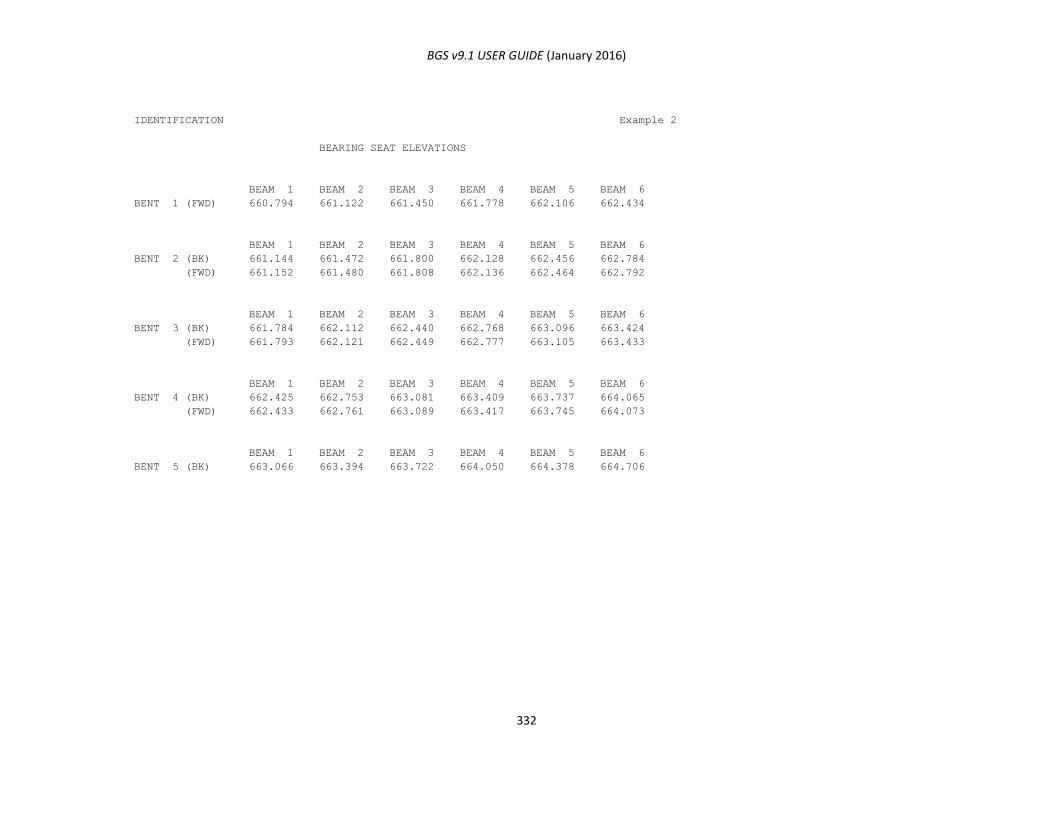
BGS v9.1 USER GUIDE (January 2016)
332
IDENTIFICATION Example 2
BEARING SEAT ELEVATIONS
BEAM 1 BEAM 2 BEAM 3 BEAM 4 BEAM 5 BEAM 6
BENT 1 (FWD) 660.794 661.122 661.450 661.778 662.106 662.434
BEAM 1 BEAM 2 BEAM 3 BEAM 4 BEAM 5 BEAM 6
BENT 2 (BK) 661.144 661.472 661.800 662.128 662.456 662.784
(FWD) 661.152 661.480 661.808 662.136 662.464 662.792
BEAM 1 BEAM 2 BEAM 3 BEAM 4 BEAM 5 BEAM 6
BENT 3 (BK) 661.784 662.112 662.440 662.768 663.096 663.424
(FWD) 661.793 662.121 662.449 662.777 663.105 663.433
BEAM 1 BEAM 2 BEAM 3 BEAM 4 BEAM 5 BEAM 6
BENT 4 (BK) 662.425 662.753 663.081 663.409 663.737 664.065
(FWD) 662.433 662.761 663.089 663.417 663.745 664.073
BEAM 1 BEAM 2 BEAM 3 BEAM 4 BEAM 5 BEAM 6
BENT 5 (BK) 663.066 663.394 663.722 664.050 664.378 664.706
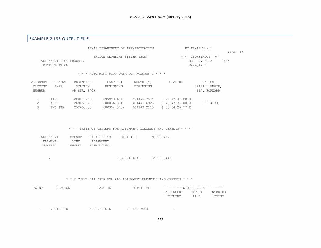
BGS v9.1 USER GUIDE (January 2016)
333
EXAMPLE 2 LS3 OUTPUT FILE
TEXAS DEPARTMENT OF TRANSPORTATION PC TEXAS V 9.1
PAGE 18
BRIDGE GEOMETRY SYSTEM (BGS) *** GEOMETRICS ***
ALIGNMENT PLOT PROCESS OCT 9, 2015 7:34
IDENTIFICATION Example 2
* * * ALIGNMENT PLOT DATA FOR ROADWAY I * * *
ALIGNMENT ELEMENT BEGINNING EAST (X) NORTH (Y) BEARING RADIUS,
ELEMENT TYPE STATION BEGINNING BEGINNING SPIRAL LENGTH,
NUMBER OR STA. BACK STA. FORWARD
1 LINE 288+10.00 599993.6616 400456.7544 S 70 47 31.00 E
2 ARC 288+55.78 600036.8946 400441.6923 S 70 47 31.00 E 2864.73
3 END STA 292+00.00 600354.3732 400309.2115 S 63 54 26.77 E
* * * TABLE OF CENTERS FOR ALIGNMENT ELEMENTS AND OFFSETS * * *
ALIGNMENT OFFSET PARALLEL TO EAST (X) NORTH (Y)
ELEMENT LINE ALIGNMENT
NUMBER NUMBER ELEMENT NO.
2 599094.4001 397736.4415
* * * CURVE FIT DATA FOR ALL ALIGNMENT ELEMENTS AND OFFSETS * * *
POINT STATION EAST (X) NORTH (Y) --------- S O U R C E ---------
ALIGNMENT OFFSET INTERIOR
ELEMENT LINE POINT
1 288+10.00 599993.6616 400456.7544 1
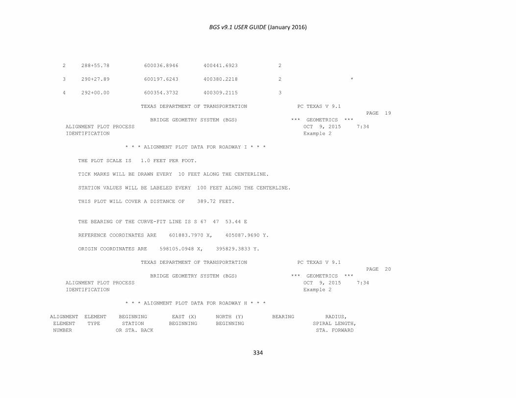
BGS v9.1 USER GUIDE (January 2016)
334
2 288+55.78 600036.8946 400441.6923 2
3 290+27.89 600197.6243 400380.2218 2 *
4 292+00.00 600354.3732 400309.2115 3
TEXAS DEPARTMENT OF TRANSPORTATION PC TEXAS V 9.1
PAGE 19
BRIDGE GEOMETRY SYSTEM (BGS) *** GEOMETRICS ***
ALIGNMENT PLOT PROCESS OCT 9, 2015 7:34
IDENTIFICATION Example 2
* * * ALIGNMENT PLOT DATA FOR ROADWAY I * * *
THE PLOT SCALE IS 1.0 FEET PER FOOT.
TICK MARKS WILL BE DRAWN EVERY 10 FEET ALONG THE CENTERLINE.
STATION VALUES WILL BE LABELED EVERY 100 FEET ALONG THE CENTERLINE.
THIS PLOT WILL COVER A DISTANCE OF 389.72 FEET.
THE BEARING OF THE CURVE-FIT LINE IS S 67 47 53.44 E
REFERENCE COORDINATES ARE 601883.7970 X, 405087.9690 Y.
ORIGIN COORDINATES ARE 598105.0948 X, 395829.3833 Y.
TEXAS DEPARTMENT OF TRANSPORTATION PC TEXAS V 9.1
PAGE 20
BRIDGE GEOMETRY SYSTEM (BGS) *** GEOMETRICS ***
ALIGNMENT PLOT PROCESS OCT 9, 2015 7:34
IDENTIFICATION Example 2
* * * ALIGNMENT PLOT DATA FOR ROADWAY H * * *
ALIGNMENT ELEMENT BEGINNING EAST (X) NORTH (Y) BEARING RADIUS,
ELEMENT TYPE STATION BEGINNING BEGINNING SPIRAL LENGTH,
NUMBER OR STA. BACK STA. FORWARD

BGS v9.1 USER GUIDE (January 2016)
335
1 LINE 22+00.00 600065.7834 400188.8718 N 19 12 11.00 E
2 END STA 27+00.00 600230.2419 400661.0512 N 19 12 11.00 E
TEXAS DEPARTMENT OF TRANSPORTATION PC TEXAS V 9.1
PAGE 21
BRIDGE GEOMETRY SYSTEM (BGS) *** GEOMETRICS ***
ALIGNMENT PLOT PROCESS OCT 9, 2015 7:34
IDENTIFICATION Example 2
* * * ALIGNMENT PLOT DATA FOR ROADWAY H * * *
THE PLOT SCALE IS 1.0 FEET PER FOOT.
TICK MARKS WILL BE DRAWN EVERY 10 FEET ALONG THE CENTERLINE.
STATION VALUES WILL BE LABELED EVERY 100 FEET ALONG THE CENTERLINE.
TEXAS DEPARTMENT OF TRANSPORTATION PC TEXAS V 9.1
PAGE 69
BRIDGE GEOMETRY SYSTEM (BGS) *** GEOMETRICS ***
PLOT SUMMARY OCT 9, 2015 7:34
IDENTIFICATION Example 2
PLOTTER SUMMARY REPORT PLRPT
*** GRAPHICS PLOT ***
PLOT PLOT ROAD- LENGTH WIDTH ACTIVE PENS (*) PLRPT
COMMAND TYPE WAY (FEET) (FEET) 1 2 3 4 5 6 7 8 PLRPT
----------------------------------------------------------- PLRPT
1 APLT I 0.0 0.0 * - - - - - - - PLRPT
2 APLT H 0.0 0.0 * - - - - - - - PLRPT
3 CONT I 0.0 0.0 * - - - - - - - PLRPT
4 CONT H 0.0 0.0 * - - - - - - - PLRPT
5 SLAB H 0.0 0.0 - - - * - - - - PLRPT
6 SLAB H 0.0 0.0 - - - * - - - - PLRPT
7 SLAB H 0.0 0.0 - - - * - - - - PLRPT
8 SLAB H 0.0 0.0 - - - * - - - - PLRPT
9 FOPT H 411.0 502.0 - - - * - - - - PLRPT

BGS v9.1 USER GUIDE (January 2016)
336
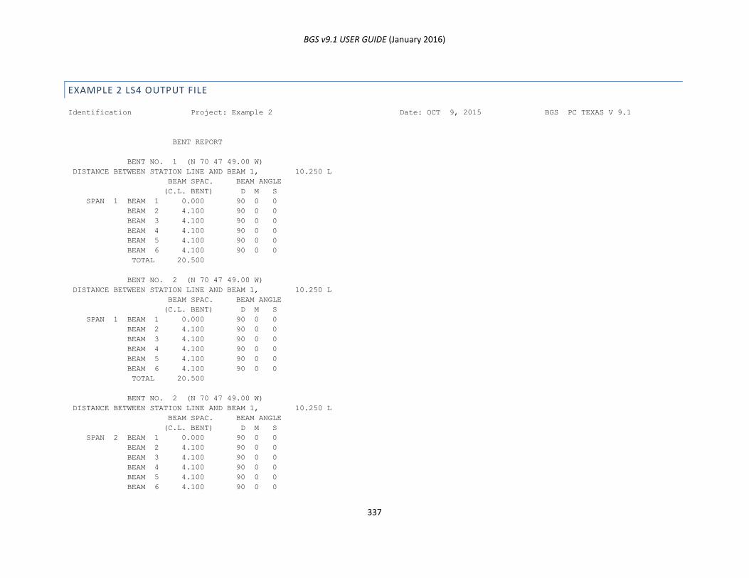
BGS v9.1 USER GUIDE (January 2016)
337
EXAMPLE 2 LS4 OUTPUT FILE
Identification Project: Example 2 Date: OCT 9, 2015 BGS PC TEXAS V 9.1
BENT REPORT
BENT NO. 1 (N 70 47 49.00 W)
DISTANCE BETWEEN STATION LINE AND BEAM 1, 10.250 L
BEAM SPAC. BEAM ANGLE
(C.L. BENT) D M S
SPAN 1 BEAM 1 0.000 90 0 0
BEAM 2 4.100 90 0 0
BEAM 3 4.100 90 0 0
BEAM 4 4.100 90 0 0
BEAM 5 4.100 90 0 0
BEAM 6 4.100 90 0 0
TOTAL 20.500
BENT NO. 2 (N 70 47 49.00 W)
DISTANCE BETWEEN STATION LINE AND BEAM 1, 10.250 L
BEAM SPAC. BEAM ANGLE
(C.L. BENT) D M S
SPAN 1 BEAM 1 0.000 90 0 0
BEAM 2 4.100 90 0 0
BEAM 3 4.100 90 0 0
BEAM 4 4.100 90 0 0
BEAM 5 4.100 90 0 0
BEAM 6 4.100 90 0 0
TOTAL 20.500
BENT NO. 2 (N 70 47 49.00 W)
DISTANCE BETWEEN STATION LINE AND BEAM 1, 10.250 L
BEAM SPAC. BEAM ANGLE
(C.L. BENT) D M S
SPAN 2 BEAM 1 0.000 90 0 0
BEAM 2 4.100 90 0 0
BEAM 3 4.100 90 0 0
BEAM 4 4.100 90 0 0
BEAM 5 4.100 90 0 0
BEAM 6 4.100 90 0 0
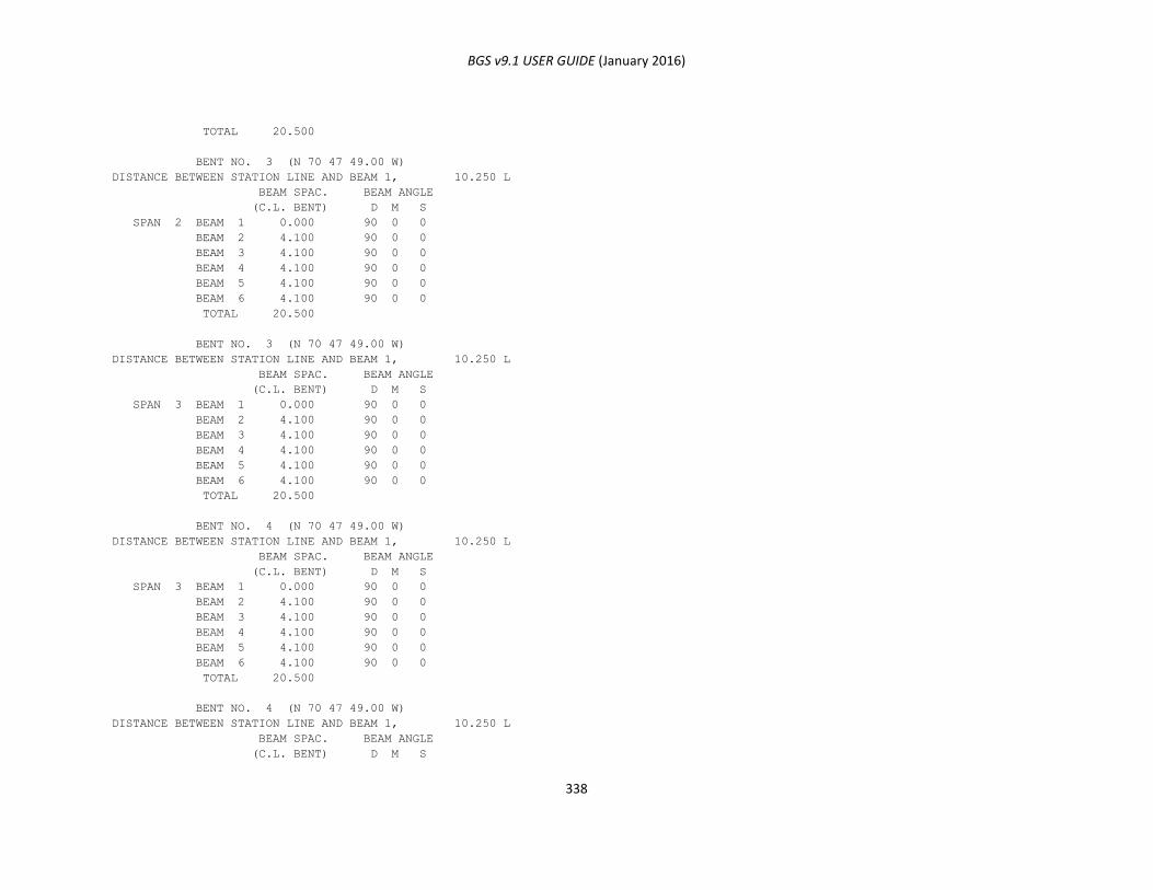
BGS v9.1 USER GUIDE (January 2016)
338
TOTAL 20.500
BENT NO. 3 (N 70 47 49.00 W)
DISTANCE BETWEEN STATION LINE AND BEAM 1, 10.250 L
BEAM SPAC. BEAM ANGLE
(C.L. BENT) D M S
SPAN 2 BEAM 1 0.000 90 0 0
BEAM 2 4.100 90 0 0
BEAM 3 4.100 90 0 0
BEAM 4 4.100 90 0 0
BEAM 5 4.100 90 0 0
BEAM 6 4.100 90 0 0
TOTAL 20.500
BENT NO. 3 (N 70 47 49.00 W)
DISTANCE BETWEEN STATION LINE AND BEAM 1, 10.250 L
BEAM SPAC. BEAM ANGLE
(C.L. BENT) D M S
SPAN 3 BEAM 1 0.000 90 0 0
BEAM 2 4.100 90 0 0
BEAM 3 4.100 90 0 0
BEAM 4 4.100 90 0 0
BEAM 5 4.100 90 0 0
BEAM 6 4.100 90 0 0
TOTAL 20.500
BENT NO. 4 (N 70 47 49.00 W)
DISTANCE BETWEEN STATION LINE AND BEAM 1, 10.250 L
BEAM SPAC. BEAM ANGLE
(C.L. BENT) D M S
SPAN 3 BEAM 1 0.000 90 0 0
BEAM 2 4.100 90 0 0
BEAM 3 4.100 90 0 0
BEAM 4 4.100 90 0 0
BEAM 5 4.100 90 0 0
BEAM 6 4.100 90 0 0
TOTAL 20.500
BENT NO. 4 (N 70 47 49.00 W)
DISTANCE BETWEEN STATION LINE AND BEAM 1, 10.250 L
BEAM SPAC. BEAM ANGLE
(C.L. BENT) D M S
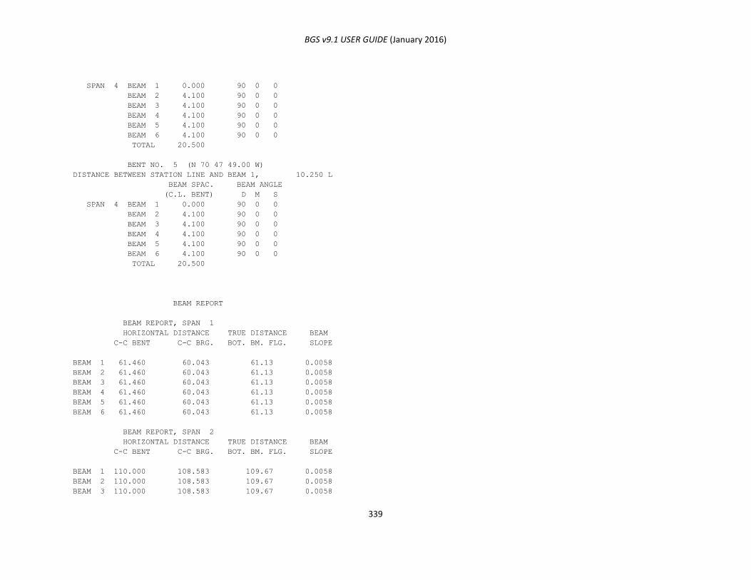
BGS v9.1 USER GUIDE (January 2016)
339
SPAN 4 BEAM 1 0.000 90 0 0
BEAM 2 4.100 90 0 0
BEAM 3 4.100 90 0 0
BEAM 4 4.100 90 0 0
BEAM 5 4.100 90 0 0
BEAM 6 4.100 90 0 0
TOTAL 20.500
BENT NO. 5 (N 70 47 49.00 W)
DISTANCE BETWEEN STATION LINE AND BEAM 1, 10.250 L
BEAM SPAC. BEAM ANGLE
(C.L. BENT) D M S
SPAN 4 BEAM 1 0.000 90 0 0
BEAM 2 4.100 90 0 0
BEAM 3 4.100 90 0 0
BEAM 4 4.100 90 0 0
BEAM 5 4.100 90 0 0
BEAM 6 4.100 90 0 0
TOTAL 20.500
BEAM REPORT
BEAM REPORT, SPAN 1
HORIZONTAL DISTANCE TRUE DISTANCE BEAM
C-C BENT C-C BRG. BOT. BM. FLG. SLOPE
BEAM 1 61.460 60.043 61.13 0.0058
BEAM 2 61.460 60.043 61.13 0.0058
BEAM 3 61.460 60.043 61.13 0.0058
BEAM 4 61.460 60.043 61.13 0.0058
BEAM 5 61.460 60.043 61.13 0.0058
BEAM 6 61.460 60.043 61.13 0.0058
BEAM REPORT, SPAN 2
HORIZONTAL DISTANCE TRUE DISTANCE BEAM
C-C BENT C-C BRG. BOT. BM. FLG. SLOPE
BEAM 1 110.000 108.583 109.67 0.0058
BEAM 2 110.000 108.583 109.67 0.0058
BEAM 3 110.000 108.583 109.67 0.0058
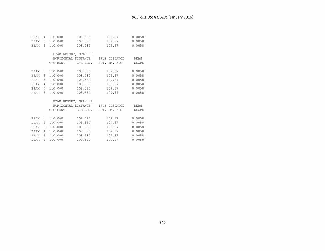
BGS v9.1 USER GUIDE (January 2016)
340
BEAM 4 110.000 108.583 109.67 0.0058
BEAM 5 110.000 108.583 109.67 0.0058
BEAM 6 110.000 108.583 109.67 0.0058
BEAM REPORT, SPAN 3
HORIZONTAL DISTANCE TRUE DISTANCE BEAM
C-C BENT C-C BRG. BOT. BM. FLG. SLOPE
BEAM 1 110.000 108.583 109.67 0.0058
BEAM 2 110.000 108.583 109.67 0.0058
BEAM 3 110.000 108.583 109.67 0.0058
BEAM 4 110.000 108.583 109.67 0.0058
BEAM 5 110.000 108.583 109.67 0.0058
BEAM 6 110.000 108.583 109.67 0.0058
BEAM REPORT, SPAN 4
HORIZONTAL DISTANCE TRUE DISTANCE BEAM
C-C BENT C-C BRG. BOT. BM. FLG. SLOPE
BEAM 1 110.000 108.583 109.67 0.0058
BEAM 2 110.000 108.583 109.67 0.0058
BEAM 3 110.000 108.583 109.67 0.0058
BEAM 4 110.000 108.583 109.67 0.0058
BEAM 5 110.000 108.583 109.67 0.0058
BEAM 6 110.000 108.583 109.67 0.0058
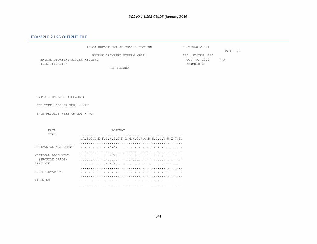
BGS v9.1 USER GUIDE (January 2016)
341
EXAMPLE 2 LS5 OUTPUT FILE
TEXAS DEPARTMENT OF TRANSPORTATION PC TEXAS V 9.1
PAGE 70
BRIDGE GEOMETRY SYSTEM (BGS) *** SYSTEM ***
BRIDGE GEOMETRY SYSTEM REQUEST OCT 9, 2015 7:34
IDENTIFICATION Example 2
RUN REPORT
UNITS - ENGLISH (DEFAULT)
JOB TYPE (OLD OR NEW) - NEW
SAVE RESULTS (YES OR NO) - NO
DATA ROADWAY
TYPE .....................................................
.A.B.C.D.E.F.G.H.I.J.K.L.M.N.O.P.Q.R.S.T.U.V.W.X.Y.Z.
.....................................................
HORIZONTAL ALIGNMENT . . . . . . . .X.X. . . . . . . . . . . . . . . . . .
.....................................................
VERTICAL ALIGNMENT . . . . . . .-.X.X. . . . . . . . . . . . . . . . . .
(PROFILE GRADE) .....................................................
TEMPLATE . . . . . . .-.X.X. . . . . . . . . . . . . . . . . .
.....................................................
SUPERELEVATION . . . . . . .-. . . . . . . . . . . . . . . . . . . .
.....................................................
WIDENING . . . . . . .-. . . . . . . . . . . . . . . . . . . .
.....................................................
BGS v9.1 USER GUIDE (January 2016)
342
SYSTEM CARD REPORT OUTPUT EXAMPLE
This is a place holder for the indicated section to be considered for a future edition of this user guide.
DIAGNOSTIC MESSAGES REPORT OUTPUT EXAMPLE
This is a place holder for the indicated section to be considered for a future edition of this user guide.
COMMAND (RG) REPORT OUTPUT EXAMPLES
This is a place holder for the indicated section to be considered for a future edition of this user guide.
GENERAL GEOMETRY COMMAND REPORT OUTPUT
This is a place holder for the indicated section to be considered for a future edition of this user guide.
BRIDGE GEOMETRY COMMAND REPORT OUTPUT
This is a place holder for the indicated section to be considered for a future edition of this user guide.
VARIOUS EXAMPLE BRIDGE GEOMETRY REPORTS
This is a place holder for the indicated section to be considered for a future edition of this user guide.
BEARING SEAT ELEVATIONS REPORT
This is a place holder for the indicated section to be considered for a future edition of this user guide.
PLOTTING COMMAND REPORT OUTPUT
This is a place holder for the indicated section to be considered for a future edition of this user guide.
BGS v9.1 USER GUIDE (January 2016)
343
ROADWAY ELEVATIONS REPORT OUTPUT
This is a place holder for the indicated section to be considered for a future edition of this user guide.
ALIGNMENT RELATIONSHIP REPORT OUTPUT
This is a place holder for the indicated section to be considered for a future edition of this user guide.
ROADWAY DESIGN DATA (RD) REPORT OUTPUT EXAMPLES
This is a place holder for the indicated section to be considered for a future edition of this user guide.
HORIZONTAL ALIGNMENT REPORT OUTPUT
This is a place holder for the indicated section to be considered for a future edition of this user guide.
PARALLEL ALIGNMENT REPORT OUTPUT
This is a place holder for the indicated section to be considered for a future edition of this user guide.
PROFILE GRADE (VERTICAL ALIGNMENT) REPORT OUTPUT
This is a place holder for the indicated section to be considered for a future edition of this user guide.
TEMPLATE REPORT OUTPUT
This is a place holder for the indicated section to be considered for a future edition of this user guide.
SUPERELEVATION REPORT OUTPUT
This is a place holder for the indicated section to be considered for a future edition of this user guide.
WIDENING REPORT OUTPUT
This is a place holder for the indicated section to be considered for a future edition of this user guide.
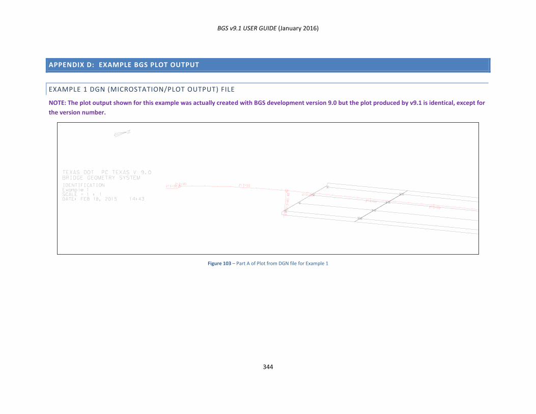
BGS v9.1 USER GUIDE (January 2016)
344
APPENDIX D: EXAMPLE BGS PLOT OUTPUT
EXAMPLE 1 DGN (MICROSTATION/PLOT OUTPUT) FILE
NOTE: The plot output shown for this example was actually created with BGS development version 9.0 but the plot produced by v9.1 is identical, except for
the version number.
Figure 103 – Part A of Plot from DGN file for Example 1
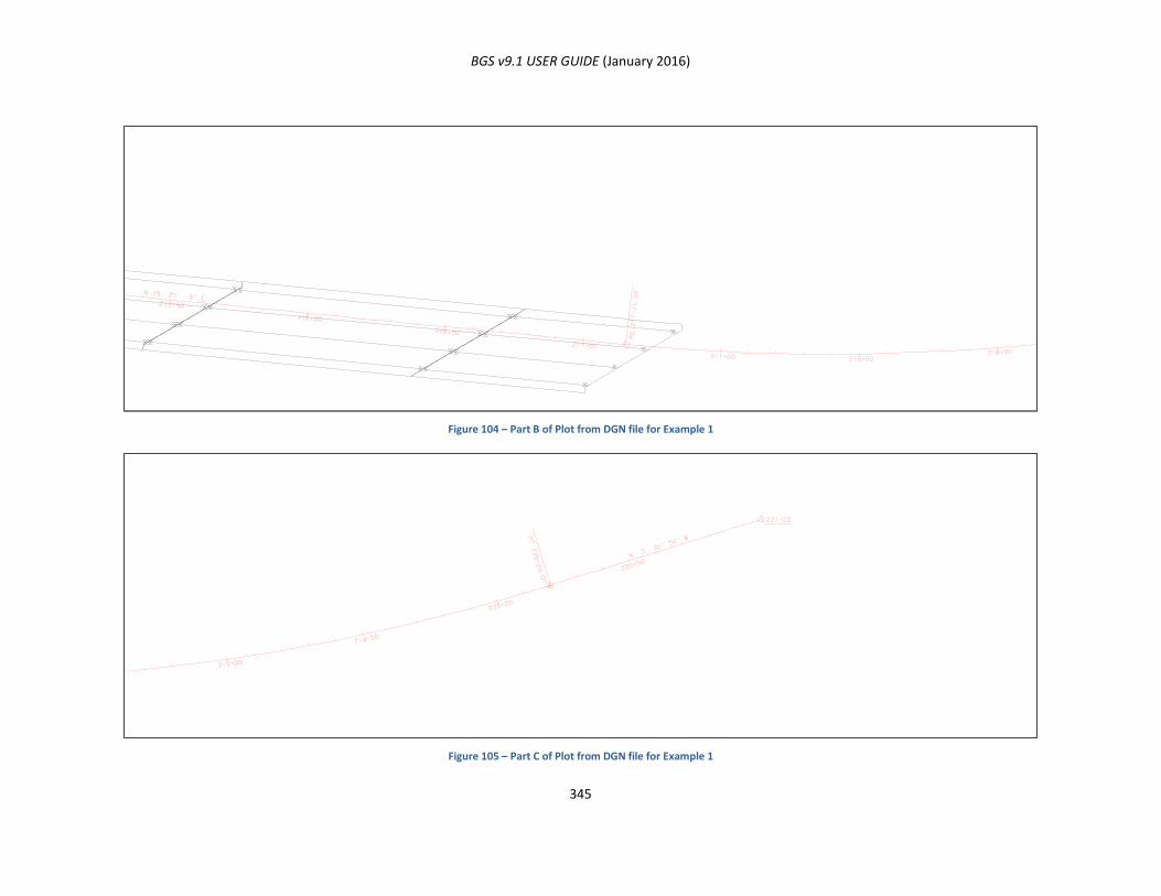
BGS v9.1 USER GUIDE (January 2016)
345
Figure 104 – Part B of Plot from DGN file for Example 1
Figure 105 – Part C of Plot from DGN file for Example 1
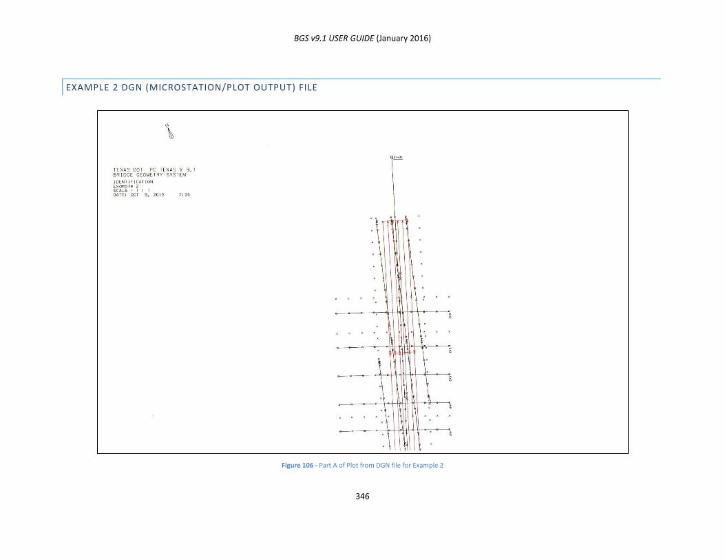
BGS v9.1 USER GUIDE (January 2016)
346
EXAMPLE 2 DGN (MICROSTATION/PLOT OUTPUT) FILE
Figure 106 - Part A of Plot from DGN file for Example 2
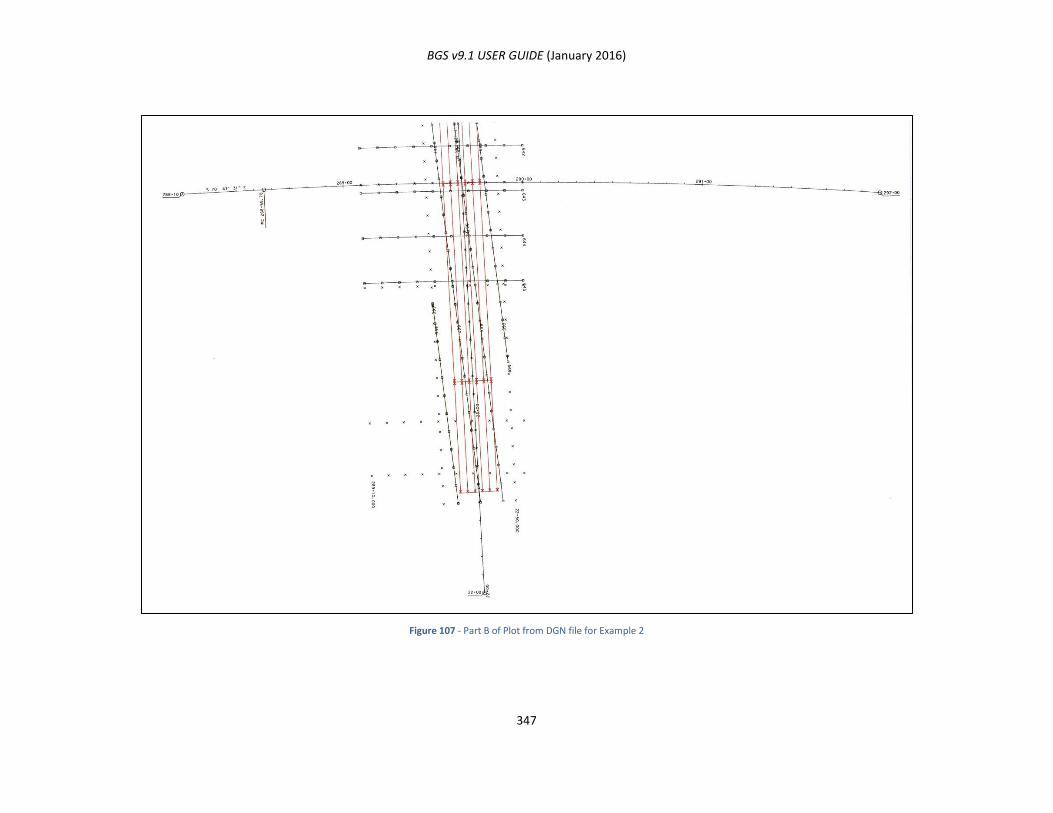
BGS v9.1 USER GUIDE (January 2016)
347
Figure 107 - Part B of Plot from DGN file for Example 2

BGS v9.1 USER GUIDE (January 2016)
348
POINT AND CURVE PLOT EXAMPLE
This is a place holder for the indicated section to be considered for a future edition of this user guide.
HORIZONTAL ALIGNMENT PLOT EXAMPLE
This is a place holder for the indicated section to be considered for a future edition of this user guide.
CONTOUR PLOT EXAMPLE
This is a place holder for the indicated section to be considered for a future edition of this user guide.
CLOSED AREA PLOT EXAMPLE
This is a place holder for the indicated section to be considered for a future edition of this user guide.
BRIDGE FRAME PLOT EXAMPLE
This is a place holder for the indicated section to be considered for a future edition of this user guide.
BRIDGE SLAB PLAN PLOT EXAMPLE
This is a place holder for the indicated section to be considered for a future edition of this user guide.
BRIDGE SLAB PROFILE PLOT EXAMPLE
This is a place holder for the indicated section to be considered for a future edition of this user guide.
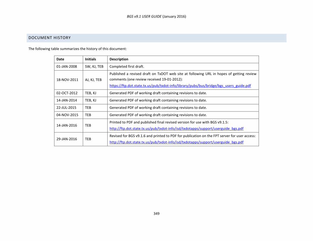
BGS v9.1 USER GUIDE (January 2016)
349
DOCUMENT HISTORY
The following table summarizes the history of this document:
Date Initials Description
01-JAN-2008 SW, KJ, TEB Completed first draft.
18-NOV-2011 AJ, KJ, TEB
Published a revised draft on TxDOT web site at following URL in hopes of getting review
comments (one review received 19-01-2012):
https://ftp.dot.state.tx.us/pub/txdot-info/library/pubs/bus/bridge/bgs_users_guide.pdf
02-OCT-2012 TEB, KJ Generated PDF of working draft containing revisions to date.
14-JAN-2014 TEB, KJ Generated PDF of working draft containing revisions to date.
22-JUL-2015 TEB Generated PDF of working draft containing revisions to date.
04-NOV-2015 TEB Generated PDF of working draft containing revisions to date.
14-JAN-2016 TEB Printed to PDF and published final revised version for use with BGS v9.1.5:
http://ftp.dot.state.tx.us/pub/txdot-info/isd/txdotapps/support/userguide_bgs.pdf
29-JAN-2016 TEB Revised for BGS v9.1.6 and printed to PDF for publication on the FPT server for user access:
http://ftp.dot.state.tx.us/pub/txdot-info/isd/txdotapps/support/userguide_bgs.pdf